inverse synthetic aperture radar imaging for concealed ... · inverse synthetic aperture radar...
TRANSCRIPT
Inverse synthetic aperture radar imaging for concealed object detection on a naturally walking person
Andrei Zhuravlev*a, Sergey Ivashova, Vladimir Razeviga, Igor Vasilieva, Timothy Bechtelb
aRemote Sensing Laboratory, Bauman Moscow State Technical University, 5 2nd Baumanskaya, Moscow, Russia 105005; bDepartment of Earth and Environment, Franklin & Marshall College,
P.O. Box 3003, Lancaster, PA USA 17604-3003
ABSTRACT
This paper describes the architecture of a microwave radar system intended for imaging concealed objects under clothing as a subject walks through the inspection area. The system uses the principle of inverse aperture which is achieved by a person’s movement past a stationary microwave sensor array. In the system, the vertical resolution is achieved by arranging microwave sensors vertically while the horizontal resolution is due to the subject’s horizontal motion. The positioning of the objects is achieved by employing a synchronous video sensor that allows coherent radar signal processing. A possible radar signal processing technique based on signal accumulation is described. Numerical experiments are conducted with the described object trajectory model. The influence of positioning errors attributed to the video positioning system is also modeled numerically. An experimental setup is designed and proposed to evaluate the suggested signal processing techniques on real data with an electro-mechanical scanner and single transceiver. It is suggested that the signal acquisition with the system can be accomplished using the stop motion technique, in which a series of changing stationary scenes is sampled and processed. Experimental radar images are demonstrated for stationary objects with concealed items and considered as reference images. Further development of the system is suggested.
Keywords: inverse synthetic aperture radar, synthetic aperture, microwave imaging, concealed object detection, concealed weapon detection, transport security, bodyscanner, security scanner
1. INTRODUCTION Modern security systems that use active electromagnetic waves involve registering the complex amplitude of a reflected wave over an area before processing the data and obtaining the image of concealed objects. These systems can be split into two categories. To the first category belong the systems that use mechanical scanning while the systems of the second kind use electronic control of spatially distributed stationary elements. Coherent processing of the registered signal in both types happens under the assumption that the recorded scene remains stationary during the data acquisition cycle, which in the systems with electronically controlled elements is an order of magnitude faster than achieved with mechanical scanning. Fast acquisition rate in electronically steered radar systems allows video streaming with normal video rates of more than a dozen frames per second. In both types of systems the signal processing is done assuming that the object remains stationary during the scan.
Two distinctive representatives of these systems are ProVision1 belonging to L-3 Communications that uses mechanical scanning by a vertically distributed array of elements, and radar system Eqo2 by Smiths Detection that employs electronic control of a 2D array of distributed elements that form a steerable focal point in the process of building a radar image3. The throughput of ProVision, as quoted in the fact sheet1, comes to 200 – 300 people at the data acquisition time of 1.5 seconds. The throughput of Eqo should not exceed that of ProVision because it relies on the subject’s cooperative self-rotation on a single spot, which is hard to achieve in less than 1.5 seconds. The throughput of both systems is further limited if the systems are deployed in areas where people wear outer clothes which have to be removed before inspection. The limitations in throughput of the systems and their prices of around $170,000 limit deployment of such security systems on public transport or other places of mass activities, which demand higher level of security.
*[email protected]; phone/fax 7 495 632-2219; rslab.ru
Sensors, and Command, Control, Communications, and Intelligence (C3I) Technologies for Homeland Security and Homeland Defense XIII, edited by Edward M. Carapezza, Proc. of SPIE Vol. 9074, 907402
© 2014 SPIE · CCC code: 0277-786X/14/$18 · doi: 10.1117/12.2051615
Proc. of SPIE Vol. 9074 907402-1
Downloaded From: http://proceedings.spiedigitallibrary.org/ on 06/06/2014 Terms of Use: http://spiedl.org/terms

To increase the throughput of active radar systems for rapidly screening many people and decrease cost of the system, this paper suggests an architecture based on the principle of inverse aperture synthesis. This concept is different from the systems with mechanical scanning in the use of target motion in the vicinity of stationary transmitters to form a synthetic aperture. The radar systems that use such aperture synthesis are currently used in radar systems for marine and air targets. In these systems, one of the difficulties is due to unknown target parameters that would allow one to calculate matched filter coefficients for signal processing4. These difficulties can be overcome for a moving person as target by using a synchronous video to record motion parameters of the walking person. These parameters will enable coherent radar processing and inverse aperture synthesis leading to a synthesized radar image, which can be calculated for every instantaneous pose of the walking person, with the synthesized image using the whole radar record acquired during the time that the subject intersects the sensitivity area.
Among the advantages of such systems are the following: the number of expensive microwave transmitters and receivers can be substantially reduced compared to systems featuring 2D arrays of microwave elements, leaving the possibility to use both dense sampling, like in classic microwave holography, and sparse sampling, as in Multiple Input-Multiple Output radar systems. Applying synchronous video recording with intelligent processing raises many possibilities for radar signal processing when complete information on trajectories is available. One possibility is to use adaptive radar signal processing based on the area of focusing. Such areas include axillary regions, the space between legs, and between torso and arms. The radar signal processing technique based on a single scattering model works poorly for these regions which typically represent spaces between strong reflectors. Another option is to use a walking person model that describes the body and clothes separately. In processing the video stream, two parallel processes may occur: the matching of the body model and the mapping of the clothing trajectory. When radar signal is focused on the body model, concealed objects attached to the body are better produced on synthetic images. Alternatively, a model focusing on loose clothing would reveal concealed objects that are attached to clothing rather than to the body. The requirements placed on the computing power of the radar signal processing system can be less demanding compared to the radar systems with 2D array of elements and real time imaging because signal processing happens more slowly as new data arrive during the time of subject’s passage through the inspection area.
2. THE RADAR SYSTEM OF INVERSE APERTURE SYNTHESIS The proposed system that uses the principle of inverse synthesis may consist of a video camera and distributed system of transmitters and receivers, as shown in Figure 1. The microwave elements should be arranged vertically to provide spatial resolution in the direction perpendicular to the subject’s trajectory. The transmitters can be arranged and steered to form various target illumination modes. They can be omni-directional and uncontrolled, or steered electronically to form a beam localized on the target to increase the effective size of the synthetic aperture and avoid illumination of other possible nearby targets. The video system, in turn, provides a synchronous video stream to make coherent radar signal processing possible. In the signal processing technique presented here it is suggested that the depth information on the dynamic scene of sounding is also provided by the video sensor. 3D imaging can be achieved by employing the same depth perception principle that is used in the Kinect motion sensor by Microsoft5 or currently developed within Project Tango by Google6. Other 3D sensing technologies can be also employed as long as they provide sufficiently high frame rate and resolution. It may be also suggested that clever use of normal video and radar data will remove the requirement for the video sensor to provide depth information.
Proc. of SPIE Vol. 9074 907402-2
Downloaded From: http://proceedings.spiedigitallibrary.org/ on 06/06/2014 Terms of Use: http://spiedl.org/terms

ü`Lriv1"fÏir,Í.o?i arid }"â..£.:13n'k5`'t,
Vis
ible
imag
eR
adar
imag
e
Figure 1. The elements of the radar system for inverse aperture synthesis.
2.1 Signal modeling
Numerical simulation of the radar processing technique consists of two phases: modeling of the received signal with established sounding geometry as shown in Figure 2, and image reconstruction. It is proposed that the trajectory of the object is known with a defined error. The moving target used in the simulation consisted of two collocated images, with one image depicting distribution of radar reflectivity and the second image corresponding to a normal optical image. This pair of collocated images is shown in Figure 2 on the right. The radar image reproduces the silhouette of the Makarov pistol, while the visible image has only the concealing object contours without any sign of the pistol. A moving trajectory of the object was given with a transformation matrix whose coefficients depend on time. The simulated flat object stayed in the same plane at a fixed distance to the transceiver array all the time.
Figure 2. Simulated geometry of sounding with target object images.
Proc. of SPIE Vol. 9074 907402-3
Downloaded From: http://proceedings.spiedigitallibrary.org/ on 06/06/2014 Terms of Use: http://spiedl.org/terms
The signal registered by the transceiver having index j on frequency f at moment tk is determined by the following formula:
,1 1
( , , ) ( , , ( , ))L M
k l m rl m
S j f t R s j f l m= =
′= ∑∑ r , (1)
where
( , ) ( , )kt
l m l m′ =r T r (2)
and
cos ( ) sin ( ) ( )sin ( ) cos ( ) ( )
0 0 1k
k k x k
t k k y k
t t r tt t r t
ϑ ϑϑ ϑ
⎡ ⎤⎢ ⎥= −⎢ ⎥⎢ ⎥⎣ ⎦
T . (3)
Indices l and m in Equations 1 and 2 are row and column numbers of the radar image with radar reflectivity coefficient Rl,m. The reference signal of transceiver j on frequency f for the point given by vector ( , )l m′r is expressed by
( , , ( , ))rs j f l m′r . The point coordinates are obtained with the transformation matrix given by Equation 3, which specifies the moving object trajectory. The type of motion produced by the matrix, as seen from its coefficients, consists of rotation and parallel shift.
2.2 Image reconstruction
The real part of the ambiguity function represents the reconstructed radar image. It was calculated on a rectangular grid defined on a basis connected with the moving object. For every object position at any given moment the value of the ambiguity function calculated for a node indexed by l, m was accumulated according to the formula:
*, , 1
1 1( ) ( ) ( , , ) ( , , ( , ))
J N
l m k l m k k n r nj n
R t R t S j t f s j f l m−= =
′ ′ ′= +∑∑ r , (4)
where
( )( , ) ( , )kt
l m T l m′ =r r . (5)
In Equations 4 and 5, the function , ( )l m kR t′ is taken as a reconstructed image when index k gets its maximum value of K. The reference signal sr is conjugated in Equation 4 when multiplied by the registered signal S. To compare the result of reconstruction, the reconstructed image was compared to the original reflectivity distribution given by Rl,m in Equation 1 and depicted in the right part of Figure 2. The results presented below are obtained with the same reflectivity distribution that follows the silhouette of the Makarov pistol. The modelling parameters that were used to obtain the following results are shown in Table 1.
Table 1. Parameter values.
Parameter Name Parameter Value
Discretization step along axis X, cm 0.25
Discretization step along axis Y, cm 0.25
Number of frequencies 1
Signal frequency, GHz 14
Distance to the object, cm 30
Number of transceivers 126
Proc. of SPIE Vol. 9074 907402-4
Downloaded From: http://proceedings.spiedigitallibrary.org/ on 06/06/2014 Terms of Use: http://spiedl.org/terms

0
10
20
E° 30
8 40c9
50
60
70
0 50 100 150Distance X, cm
Modeling volume dimensions, cm 150 (axis X), 75 (axis Y)
Transceiver distribution equidistant vertical
Distance between adjacent transceivers, cm 0.6
Time sampling interval, s 0.01
Total calculation interval, s 2
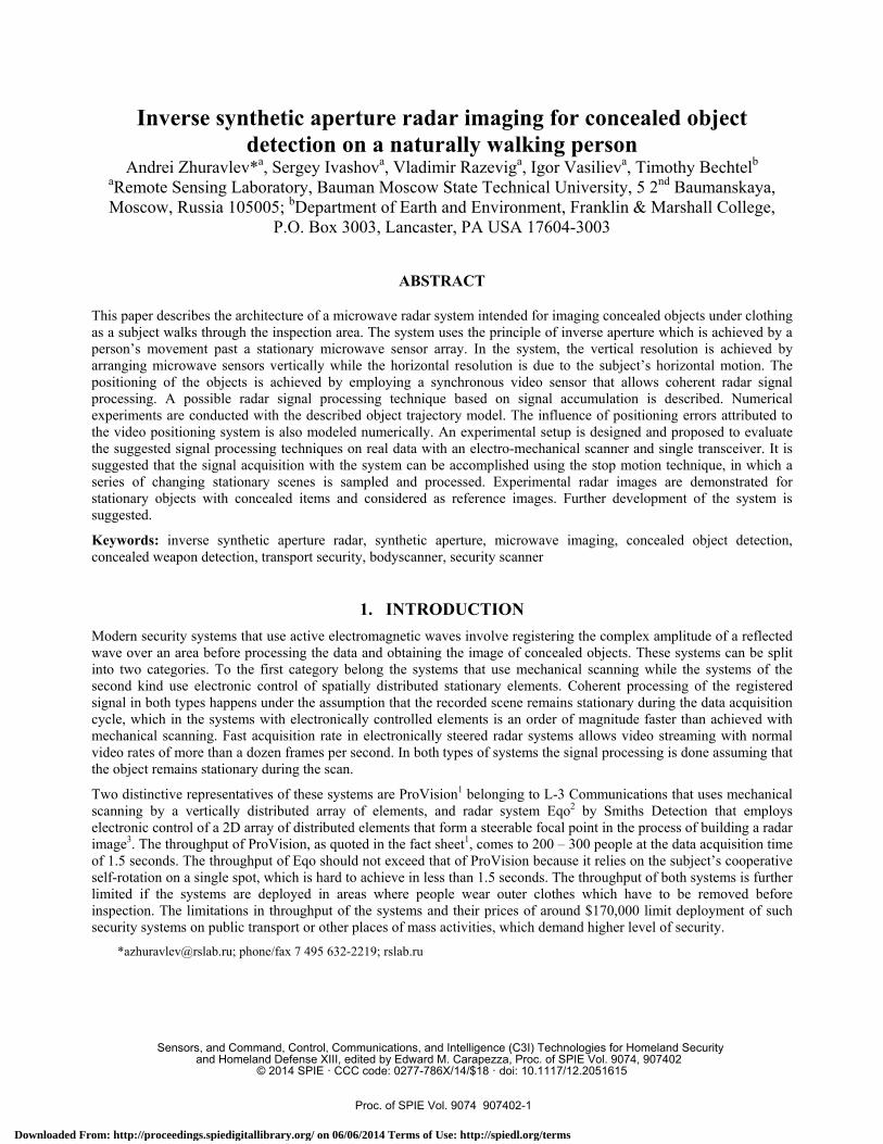
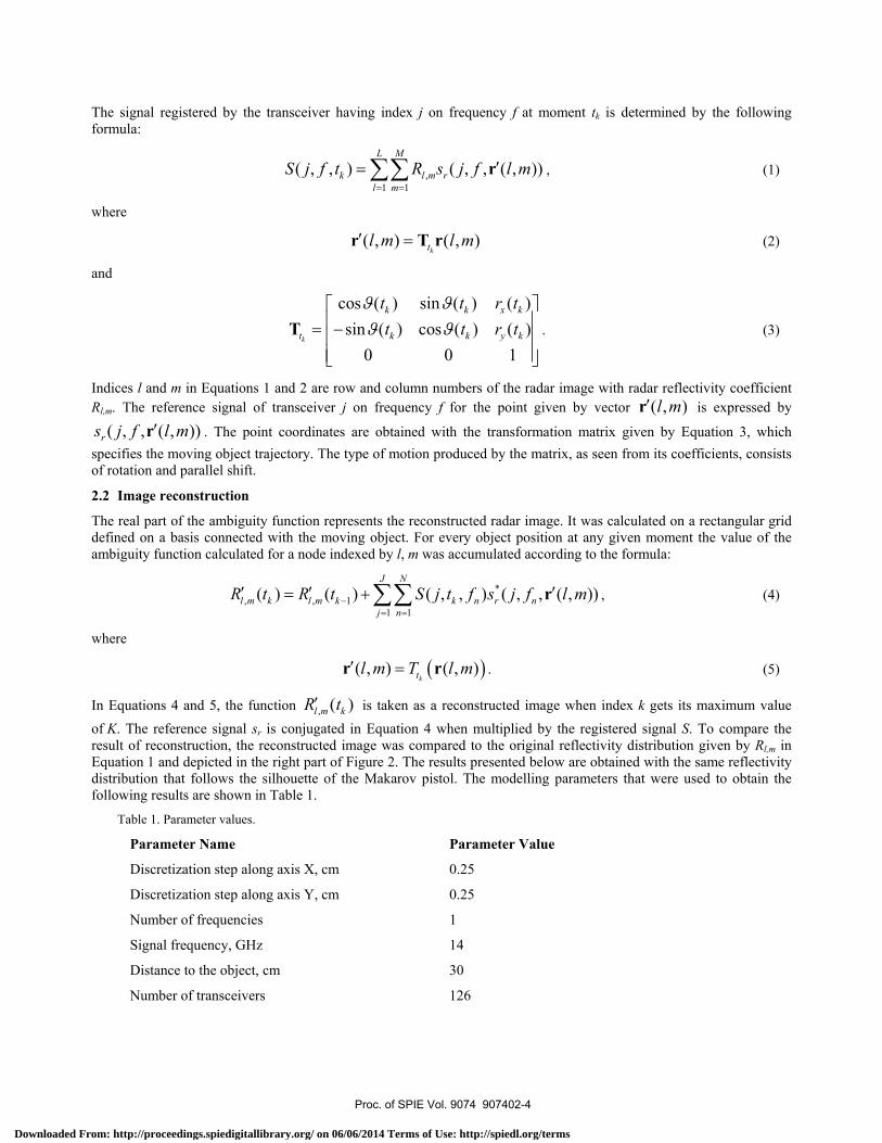
The analytical trajectory of the object in the demonstrated calculation results is given by the following transform matrix coefficients, in the notation given by Equation 3: rx=75t, ry=30t, θ=0.5πt. The graphical representation of the object trajectory is given by Figure 3, where the object-bounding box is shown for every 15th frame of its motion sequence. The imaginary part of the signal S(j, tk, f1) registered by the transceiver j at time tk on the single simulated frequency is shown in Figure 4 as a grayscale image. Accumulation of ambiguity function values during the simulated time interval according to Equation 4 leads to the object image given in Figure 5 on the right. The original object image is shown in the same figure on the left.
It should be noted that the density of the grid on the reconstructed image can be chosen independently on other grids used in calculations. Its cell size should be less than the size of the point spread function of the system defined by the sounding geometry, transceiver topology, and sounding frequency band.
Observing the reconstructed image in Figure 4, one may notice that the image background gets brighter toward the upper right corner. This is explained by the fact that the right part of the moving object was exposed longer to the transceivers due to the given trajectory. As it seen in Figure 3, it is the right part of the moving object that stays longer within range of the transceiver array. For a walking person, the limbs cover body regions such that each body region or limb gets differing exposure time. This effect can be compensated by measuring and correcting for each fragment exposure time.
Figure 3. Object trajectory with every 15th frame shown.
Proc. of SPIE Vol. 9074 907402-5
Downloaded From: http://proceedings.spiedigitallibrary.org/ on 06/06/2014 Terms of Use: http://spiedl.org/terms
20
40
6o
00
100
120
20 40 GO 00
20
40
60
80
100
120
20 30 00 30
m.j
Figure 4. Signal registered by the transceiver array.
Figure 5. Original (left) and reconstructed (right) images.
As this demonstration shows, knowledge of the object trajectory provides the opportunity to process the multi-dimensional signal coherently, and to reconstruct the radar image. Reconstruction of radar images for complex moving objects, like a walking human, can be decomposed into reconstruction of radar images of discrete fragments that are spatially arranged according to a simple walking human model.
Figure 6 gives the sequence of reconstructed radar images as it is being formed during the accumulation time wherein the object moves past the radar antenna array. It was already shown in Figure 3 that the signal appears after 0.5s and disappears at 1.1s from the start. The same evidence follows from Figure 6 where the object contours appear at 0.6s and the image ceases changing after 1.1s. This time of effective signal acquisition defines the size of the synthetic aperture and depends on the directional pattern of the transceivers, the sounding geometry, and the speed of the object. The size of the synthetic aperture defines the spatial resolution in the horizontal direction.
Proc. of SPIE Vol. 9074 907402-6
Downloaded From: http://proceedings.spiedigitallibrary.org/ on 06/06/2014 Terms of Use: http://spiedl.org/terms

0,1 s
0,2 s
0,3 s
0,4 s
0,5 s
0,6 s
0,7 s
0,8 s
0,9 s
1,0 s
1,1 s
1,2 s
1,3 s
1,4 s
1,5 s
1,6 s
1,7 s
1,8 s
Figure 6. Radar image reconstruction during signal accumulation.
The influence of object positioning errors was estimated by introducing random additive errors to the transform matrix coefficients in Equation 3, affecting two coordinates and the angle of rotation. These additive errors were in the form: [r'x, r'y] = [rx, ry] + α[ξx, ξy] – for the vector of parallel shift, and θ' = θ + βξθ – for the rotation angle. The letters without the prime symbol are the values that were used in calculating the radar signal, while the primed symbols are the values that were used in radar image synthesis. Variables ξ with indices are evenly distributed in the interval [-1/2, 1/2] and multiplied by parameters α and β for two coordinates and the angle respectively. Figure 7 gives some examples of reconstructed images when errors are present. The parameters of errors are presented in annotations on the demonstration images. The trajectory of the object relevant to these two examples is given by [rx, ry] = [75t, 30], θ = 0. This corresponds to a uniform motion with the speed of 75 cm/s along axis X without rotation. The observable distortion in the images in the form of vertical lines was not expected since the positioning errors were equally distributed along both axes.
Proc. of SPIE Vol. 9074 907402-7
Downloaded From: http://proceedings.spiedigitallibrary.org/ on 06/06/2014 Terms of Use: http://spiedl.org/terms

20
40
60
80
100
120
20 40 60 80
20
40
60
80
100
120
20 40 60 80
α = 0.5, β = 0
α = 1, β = π/90
Figure 7. Radar image reconstruction with positioning errors.
2.3 The experimental setup for signal acquisition
For the purpose of evaluating the data processing described in the previous sections, two radar systems consisting of continuous wave radars and a 2D electro-mechanical scanner were built and tested. The radars in use were modified versions of RASCAN radars7 operating in the frequency bands 6.4–6.8 and 13.8–14.6 GHz. As shown in Figure 8, they consist of transmitter and receiver modules mounted on a half-opened circular waveguide used as the antenna.
One of two electro-mechanical scanners is intended for acquiring the radar signal in the vertical plane while the other is adapted to sample in the horizontal plane. A microcontroller board is designed and programmed to control both scanners and the radars. The microcontroller board is also connected to a PC wirelessly enabling the user to control the system, setup radar and acquisition parameters, and display intermediate and processed data. The microcontroller board is visible in Figure 8 on the left. The vertical and horizontal electro-mechanical scanners are shown in Figure 9.
Figure 8. Continuous wave radars of 6.4–6.8 GHz (left) and 13.8–14.6 GHz (right) used with the electro-mechanical scanners.
Proc. of SPIE Vol. 9074 907402-8
Downloaded From: http://proceedings.spiedigitallibrary.org/ on 06/06/2014 Terms of Use: http://spiedl.org/terms

Figure 9. Electro-mechanical scanners for signal acquisition with the radars vertical (left), and horizontal (right).
At the time of writing this paper, the video system for capturing the sounding scene, including the dedicated software that facilitates conducting the experiments with stop-motion, was not fully accomplished. This technique will involve registering a series of stationary scenes with each scene changing by small increments. The current version of the software allows acquisition and reconstruction of radar images for stationary objects. Examples of test objects and the resulting radar images are shown in Figures 10 and 11.
Figure 10 (left) is a photo of a mannequin dressed in a vest and work coat with two pieces of soap hidden in the vest side pocket. The pieces of soap have coins taped on the surface. The distance to the object and the acquisition plane was 20 cm with a sounding frequency of 14.7 GHz. The two soap pieces are distinctly visible in the same figure on the right. The plan view spatial resolution of the radar image is sufficient to discern individual coins.
A photo of a subject with a pistol in position prior to concealment under a jumper is shown in Figure 11 (left). The resulting radar image acquired at 6.4 GHz is shown in the same figure on the right. In spite of lower frequency (by a factor of two) relative to the experiment with soap, the radar image still has sufficient quality to recognize a pistol. Imaging with a lower frequency is advantageous in obtaining radar images under thick or perhaps damp outer clothing.
Proc. of SPIE Vol. 9074 907402-9
Downloaded From: http://proceedings.spiedigitallibrary.org/ on 06/06/2014 Terms of Use: http://spiedl.org/terms

tiat
h r'
.}
.*A;.
.1i."
,.
.
1
{
,
Figure 10. A photo of a mannequin and its radar image at a frequency of 14.7 GHz with two pieces of soap with coins on the surface.
Figure 11. A photo of a subject with a pistol to be hidden under the jumper at the same place and the reconstructed radar image at 6.4 GHz.
3. CONCLUSION AND FUTURE WORK In this paper, it was shown by numerical experiments that image synthesis of dynamic objects is possible in a radar system with inverse aperture. Microwave inspection systems for mass transit or other public facilities are proposed as an application area for this principle. The vertical resolution in this system is achieved by arranging transmitters and receivers in a vertical array while horizontal resolution is provided by a subject’s natural movement past the inspection area defined by the array. A video system is proposed to provide necessary information on the subject’s instantaneous position and pose synchronously with a rapid sampling cycle for the radar signal so that coherent radar signal processing leading to a synthesized radar image is possible. Among expected advantages of the system are the following: significant reduction in the number of microwave transmitters and receivers compared to electronically controlled systems, an absence of moving parts, significant increase in the system throughput by acquiring the signal on-the-move, the
Proc. of SPIE Vol. 9074 907402-10
Downloaded From: http://proceedings.spiedigitallibrary.org/ on 06/06/2014 Terms of Use: http://spiedl.org/terms

possibility to apply adaptive radar processing to different body regions recognized on video to mitigate artifacts, and relaxed requirements for the signal processor of the system since processing can be done at the rate of signal acquisition.
An experimental setup was suggested and built to estimate the applicability of the described signal processing technique to real world data. It consists of a 2D electro-mechanical scanner that moves a single transceiver. Currently, the system is capable of registering radar signal from stationary objects and producing demonstrated synthetic radar images. Integration of the video sensor with its processing software is anticipated in the near future. Object motion will be imitated by the stop motion technique, a tool well known in animation. Within this approach, the mechanical scanning with radar signal acquisition and photography happens as a series of stationary scenes that change by small increments between sampling cycles. The radar samples and the photo of the sounding scene provide the input to the signal processor.
The signal processing done in numerical experiments and expressed by Equation 4 suggests signal accumulation to provide the resulting image at the very last moment. It is possible to rewrite this equation so that it gives the final image for an instant pose at any desired moment if the whole record is already accumulated by taking into account both previous and successive video frames and samples of radar signal.
Relying on a video sensor for extracting object trajectory requires adequate description of a walking person model and the ways of establishing its basic and motion parameters by video sensor output alone, or in combination with radar data. This model may include separate description of body and clothes to provide synthetic radar images for concealed objects that are attached to the body or being held inside loosely moving clothes.
In numerical experiments, this study considered a sounding geometry where only one side of the object was illuminated. Of significant interest for inspection systems is a geometry of sounding where the inspected person walks towards the sensor and synthetic images of the person’s front, back are obtained in addition to the side views.
In the numerical simulation it was suggested that the video sensor additionally provides depth information that can be used to establish trajectory of moving objects in 3D. This requirement can be met by combined processing of video and radar data without explicitly knowing the depth from the video sensor.
ACKNOWLEDGEMENT
This work is supported by Russian Foundation for Basic Research.
The first author is very grateful to Dr. Timothy Bechtel and Enviroscan, Inc. for forwarding the invitation letter from SPIE by fast courier service, so that the author could apply for and get a travel visa in proper time and participate in the conference.
REFERENCES
[1] “ProVision® Imaging,” <http://www.sds.l-3com.com/advancedimaging/provision.htm> (26 March 2014). [2] “eqo,” <http://www.smithsdetection.com/people-screening-systems/60-people-screening-systems/eqo.html>
(26 March 2014). [3] Abdillah, M. B., Lyons, B., Entchev, E., “Identification of potential threat materials using active electromagnetic
waves,” US Patent 8 390 504 B2, March 5, 2013. [4] Skolnik, M., [Radar Handbook], McGraw-Hill, New York, NY, 3rd Edition (2008). [5] “Kinect for Windows,” <http://www.microsoft.com/en-us/kinectforwindows/> (26 March 2014). [6] “Project Tango,” <https://www.google.com/atap/projecttango/> (26 March 2014). [7] Zhuravlev, A.V., Ivashov, S.I., Razevig, V.V., Vasiliev, I.A., Bugaev, A.S., "Holographic subsurface radar
RASCAN-5," 7th International Workshop on Advanced Ground Penetrating Radar (IWAGPR), 2-5 July 2013.
Proc. of SPIE Vol. 9074 907402-11
Downloaded From: http://proceedings.spiedigitallibrary.org/ on 06/06/2014 Terms of Use: http://spiedl.org/terms