introduction to the updated 100-year crossing design
TRANSCRIPT

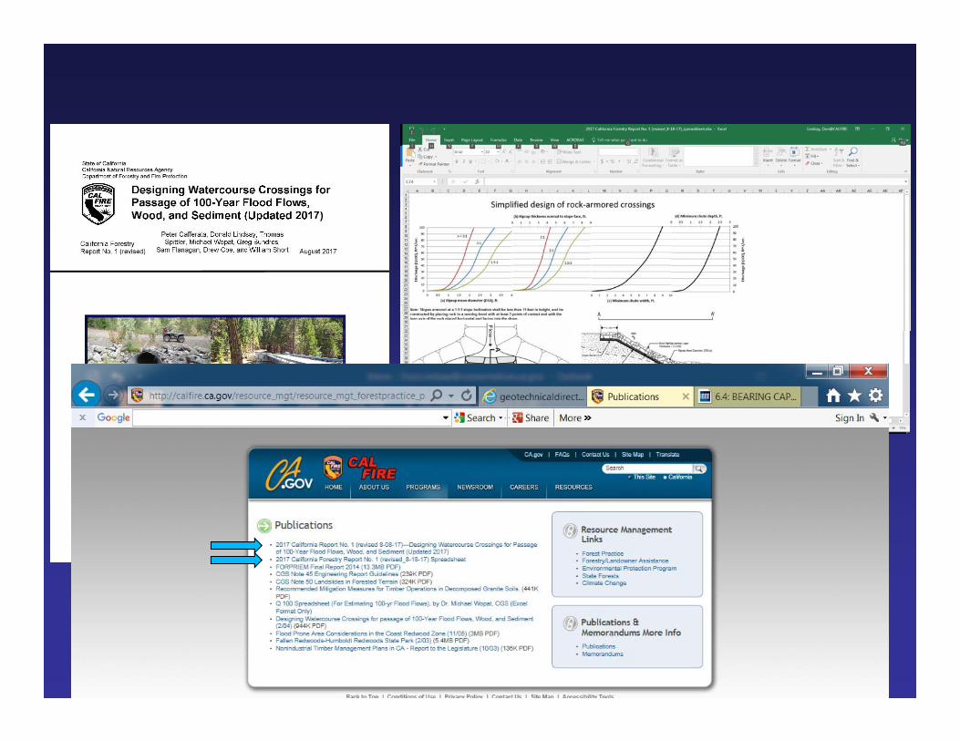
Introduction to the Updated 100-year Crossing Design Guidance Report
Don Lindsay, CEG, [email protected]
California Geological Survey

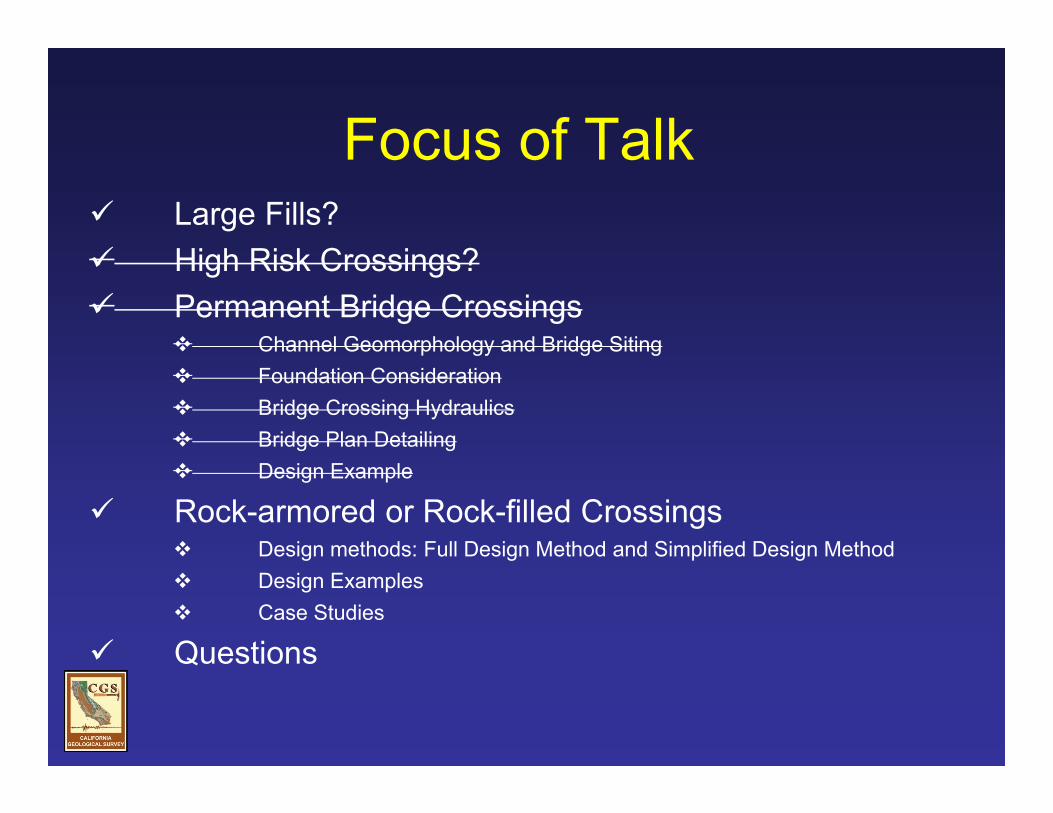
Focus of Talk Large Fills? High Risk Crossings? Permanent Bridge Crossings
Channel Geomorphology and Bridge Siting Foundation Consideration Bridge Crossing Hydraulics Bridge Plan Detailing Design Example
Rock-armored or Rock-filled Crossings Design methods: Full Design Method and Simplified Design Method Design Examples Case Studies
Questions
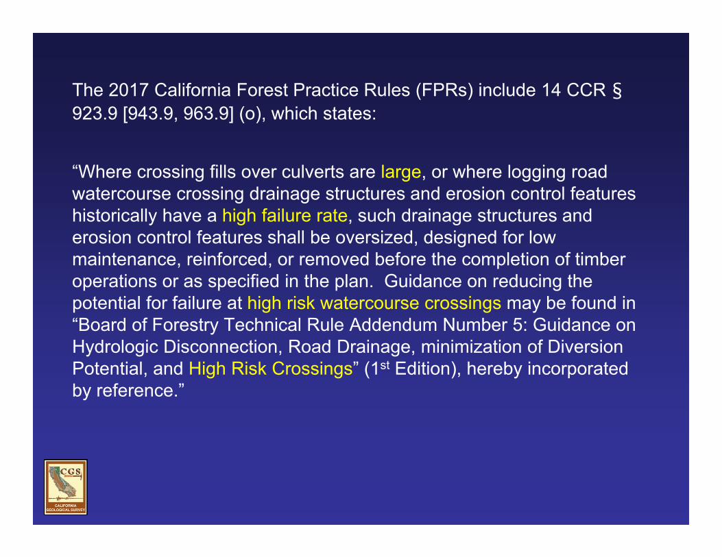
The 2017 California Forest Practice Rules (FPRs) include 14 CCR §923.9 [943.9, 963.9] (o), which states:
“Where crossing fills over culverts are large, or where logging road watercourse crossing drainage structures and erosion control features historically have a high failure rate, such drainage structures and erosion control features shall be oversized, designed for low maintenance, reinforced, or removed before the completion of timber operations or as specified in the plan. Guidance on reducing the potential for failure at high risk watercourse crossings may be found in “Board of Forestry Technical Rule Addendum Number 5: Guidance on Hydrologic Disconnection, Road Drainage, minimization of Diversion Potential, and High Risk Crossings” (1st Edition), hereby incorporated by reference.”

Large Fill?
Existing thresholds:
ODF = fill height >15’WQ = fill height >25’ or fill volume of >500 cy

Large Fill =
Proposed thresholds:
fill height above culvert outlet >15’, or fill volume of >500 cy


High Risk Crossings?

High Risk Crossing, defined:
A crossing that is considered as presenting a high environmental and/or human life-safety risk that requires considerable more thought and attention in design and construction.
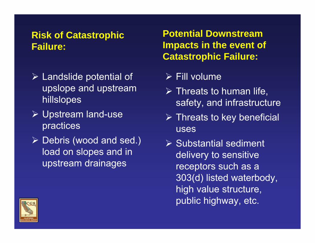
Risk of Catastrophic Failure:
Landslide potential of upslope and upstream hillslopes
Upstream land-use practices
Debris (wood and sed.) load on slopes and in upstream drainages
Potential Downstream Impacts in the event of Catastrophic Failure:
Fill volume Threats to human life,
safety, and infrastructure Threats to key beneficial
uses Substantial sediment
delivery to sensitive receptors such as a 303(d) listed waterbody, high value structure, public highway, etc.

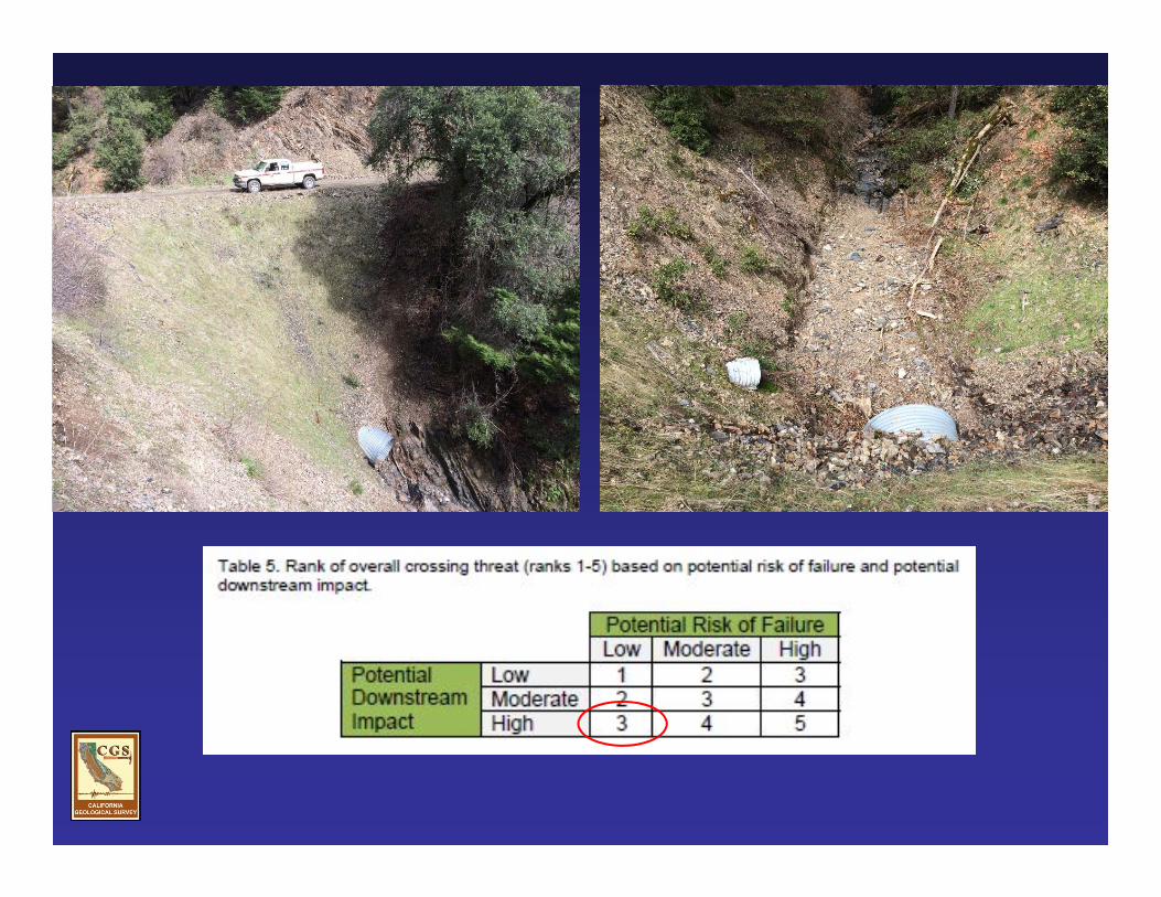

Why is this important?
It provides flexibility!

Focus of Talk Large Fills? High Risk Crossings? Permanent Bridge Crossings
Channel Geomorphology and Bridge Siting Foundation Consideration Bridge Crossing Hydraulics Bridge Plan Detailing Design Example
Rock-armored or Rock-filled Crossings Design methods: Full Design Method and Simplified Design Method Design Examples Case Studies
Questions
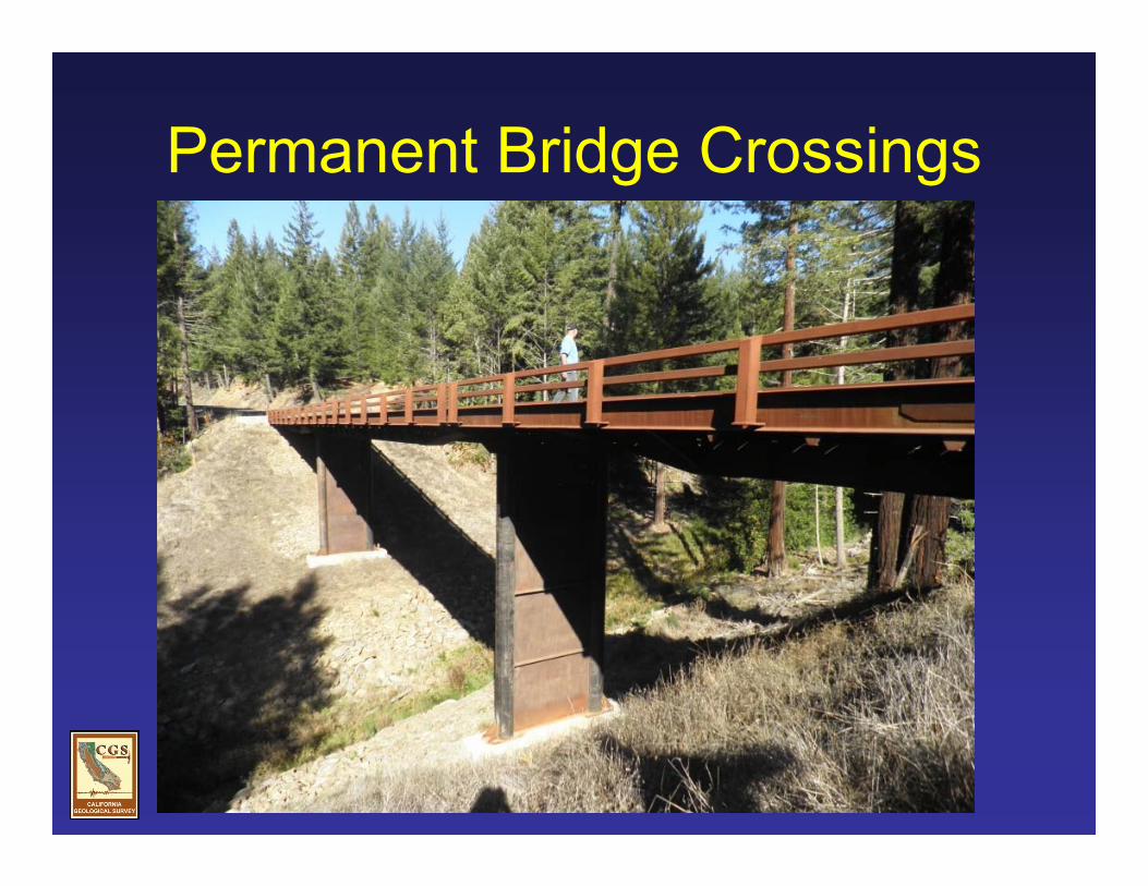
Permanent Bridge Crossings

In accordance with § 6731 of the California Professional Engineers Act, permanent bridge structures are to be engineered by a California Registered Civil Engineer.

In accordance with the Professional Foresters Law (PRC § 750 et sec.), RPFs often identify the location, develop preliminary plans for the crossing based on field conditions, and propose a conceptual crossing design for agency review and comment.

Permanent Bridge Crossings
Channel Geomorphology and Bridge SitingFoundation ConsiderationBridge Crossing HydraulicsBridge Plan Detailing

Channel Geomorphology and Bridge Siting
If you are considering a permanent bridge crossing, ask the following 5 questions:

1. Where is the crossing location in the watershed, and how does the stream transport water, sediment, and wood at that location?
USFS

2. How is the channel configured?o What is the degree of channel confinement?o Is there floodplain conveyance? If so, how much, and are there
multiple channels, side channels, or backwater alcoves?o Does the channel contain evidence that the stream may migrate
(move laterally) and affect the foundation system? o What is the range of vertical fluctuation (either due to
aggradation or degradation) of the streambed?
G. Keller


G. Keller

77
78
79
80
81
82
83
84
85
86
87
88
89
90
91
92
0 100 200 300 400 500 600
Distance (ft)
Ele
vatio
n (ft
)
StreambedWater SurfacePipe LocationPipe Bed MaterialExtent of scourOld Pipe
Long Profile – Foundation Design AidLowest potential scour depth. Place foundation below this line with sufficient depth to develop bearing capacity and good interlocking of bed materials.
Long term stablegradient?
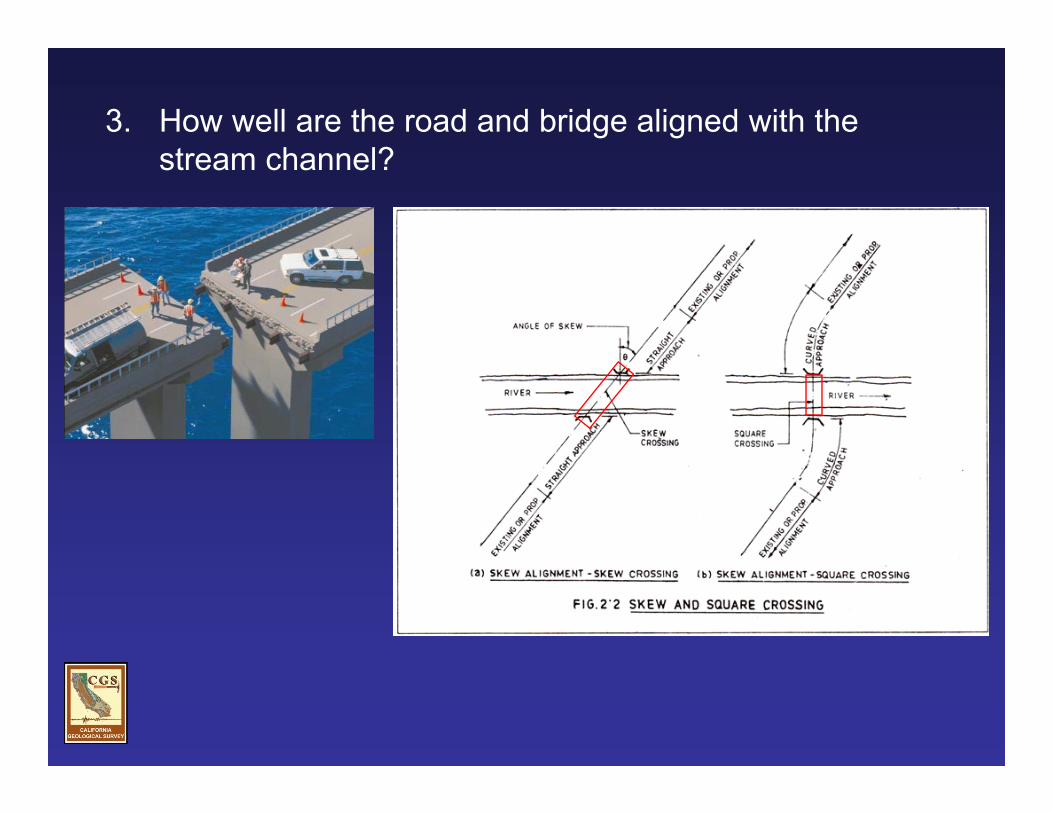
3. How well are the road and bridge aligned with the stream channel?

4. Is the channel stable, or is it adjusting to recent large-scale disturbances?
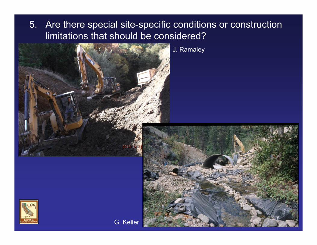
5. Are there special site-specific conditions or construction limitations that should be considered?
G. Keller
J. Ramaley

Foundation Consideration
The following are 4 important aspects of bridge foundation design to consider:
G. Keller

1. Where possible, the bridge should span the entire width of the channel above the anticipated 100-year flood flow elevation and the foundation elements should not encroach into the 100-year floodplain.

2. Footings should be founded on firm soil or bedrock that is capable of supporting the anticipated loads.
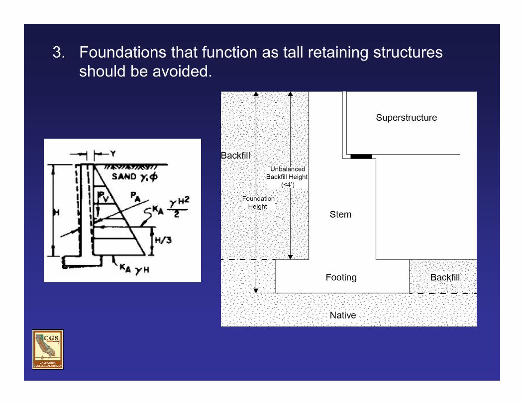
3. Foundations that function as tall retaining structures should be avoided.


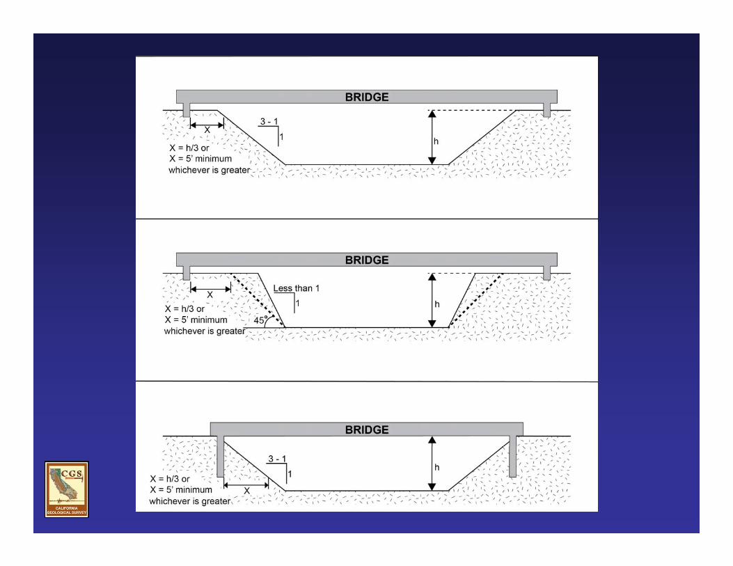
4. Avoid placing shallow footings on or adjacent to descending slopes steeper than 3h:1v (units horizontal, h, to units vertical, v), or about 33 percent.
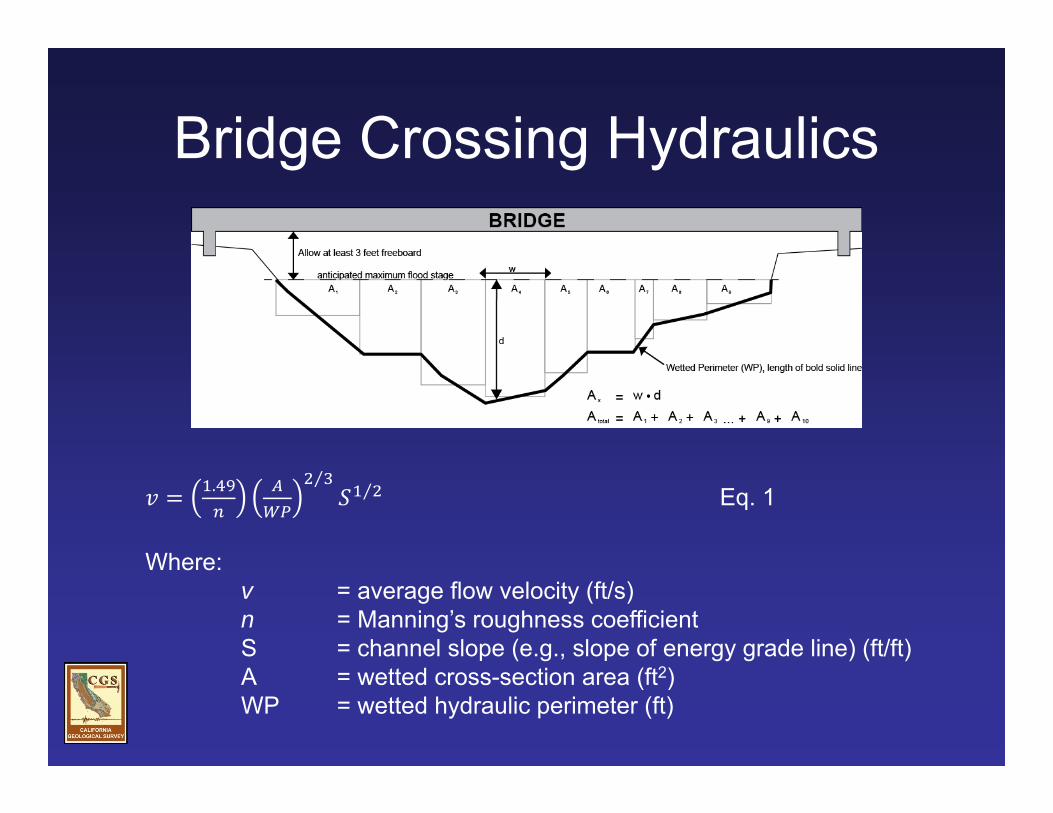
Bridge Crossing Hydraulics
. ⁄⁄ Eq. 1
Where:v = average flow velocity (ft/s)n = Manning’s roughness coefficient S = channel slope (e.g., slope of energy grade line) (ft/ft)A = wetted cross-section area (ft2)WP = wetted hydraulic perimeter (ft)
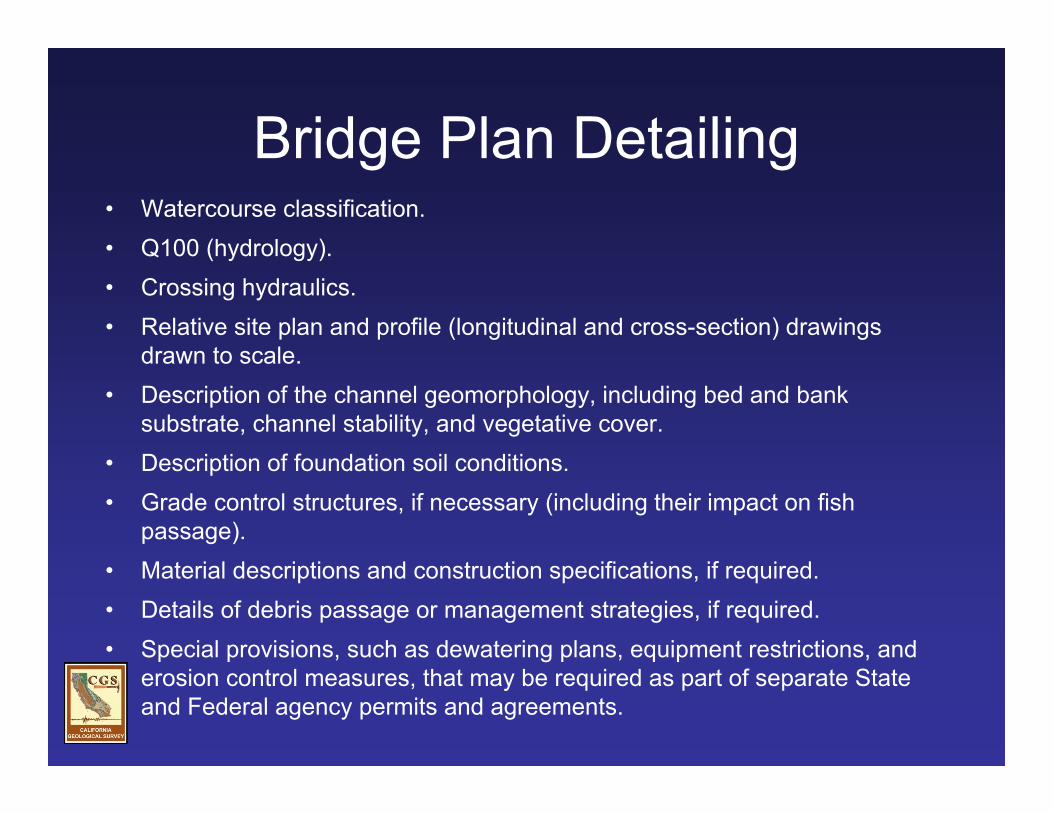
Bridge Plan Detailing• Watercourse classification.• Q100 (hydrology).• Crossing hydraulics.• Relative site plan and profile (longitudinal and cross-section) drawings
drawn to scale.• Description of the channel geomorphology, including bed and bank
substrate, channel stability, and vegetative cover.• Description of foundation soil conditions.• Grade control structures, if necessary (including their impact on fish
passage). • Material descriptions and construction specifications, if required.• Details of debris passage or management strategies, if required.• Special provisions, such as dewatering plans, equipment restrictions, and
erosion control measures, that may be required as part of separate State and Federal agency permits and agreements.

Bridge Plan Detailing
Appendix E
Focus of Talk Large Fills? High Risk Crossings? Permanent Bridge Crossings
Channel Geomorphology and Bridge Siting Foundation Consideration Bridge Crossing Hydraulics Bridge Plan Detailing Design Example
Rock-armored or Rock-filled Crossings Design methods: Full Design Method and Simplified Design Method Design Examples Case Studies
Questions
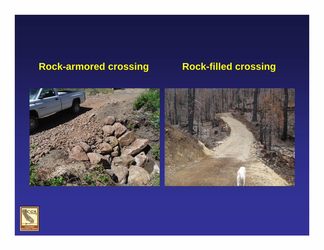
Rock-armored crossing Rock-filled crossing

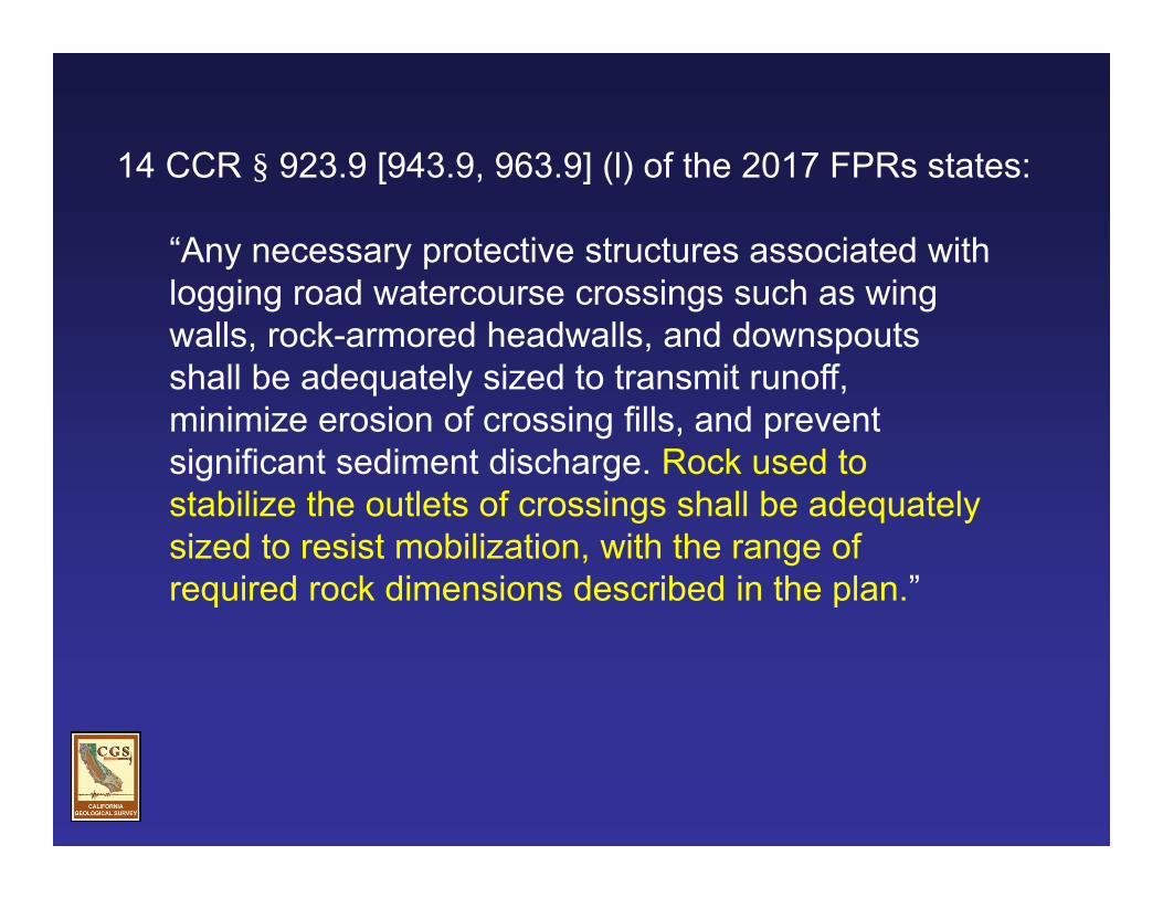
14 CCR § 923.9 [943.9, 963.9] (l) of the 2017 FPRs states:
“Any necessary protective structures associated with logging road watercourse crossings such as wing walls, rock-armored headwalls, and downspouts shall be adequately sized to transmit runoff, minimize erosion of crossing fills, and prevent significant sediment discharge. Rock used to stabilize the outlets of crossings shall be adequately sized to resist mobilization, with the range of required rock dimensions described in the plan.”


USBR


Design Method – Full

Design Method – Full

Description Coefficient of Uniformity Porosity Narrow or “single sized” (e.g., “uniform”) 1.2 to 1.5 0.35 to 0.46 Wide (e.g., “well graded”) 1.5 to 2.5 0.25 to 0.40 Very Wide (nominally, “quarry run”) Greater than 2.5 0.20 to 0.35
Cu = D60/D10 n
Design Method – Full

= Depends on site conditions, but for most Class II and III watercourses it should be about 1.5x – 2x active channel width
Chute width?

Design Method – Full

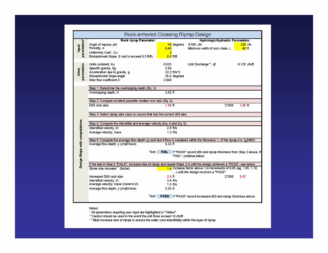
Design Method – Simplified


Assumption 1: The proposed crossing has anticipated 100-year flood flows of 100 cfs or less.
Assumption 2: The rock riprap used to armor the crossing has the following general properties. The material is angular with an angle of repose, ϕ, of 40 degrees, is well graded with a uniformity coefficient, Cu, equal to 1.75 and a porosity, n, of 0.40, and has a specific gravity, Sg, of 2.65.
Assumption 3: The highest unit discharge occurs near the toe of the outfall where flows are re-concentrated into the natural channel and is based on an assumed chute/outfall width roughly equivalent to 2 times the diameter of an appropriately sized, inlet-controlled culvert flowing full (HW/D=1) with the 100-year flood flow at the site.

Assumption 4: The rock chute/outfall down the fillslope has a minimum cross-section geometry equal to a trapezoid with a minimum base width equivalent to 2 times the diameter of an appropriately sized, inlet-controlled culvert flowing full with the 100-year flood flow and a minimum depth calculated using the broad-crested weir formula, and side slopes inclined at 2h:1v.
Assumption 5: Crossings with fillslopes as steep as 67 percent are stable against overtopping flows, provided they (1) have less than 15 feet of maximum fill height, and (2) are constructed with angular rocks that are machine placed (as opposed to randomly dumped) and oriented in a running bond with at least three points of contact and with the long axis of the individual rocks sloping slightly into the fillslope.
Assumption 6: The rock-armored crossings are constructed following sound construction standards.
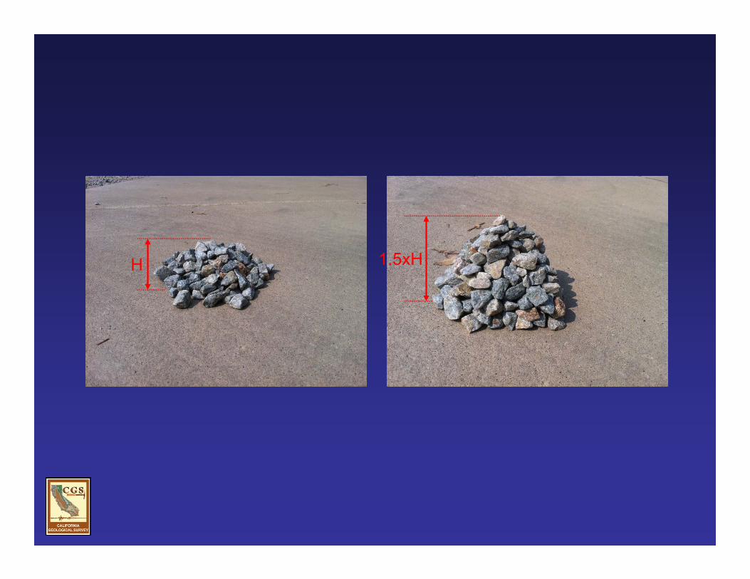
H 1.5xH


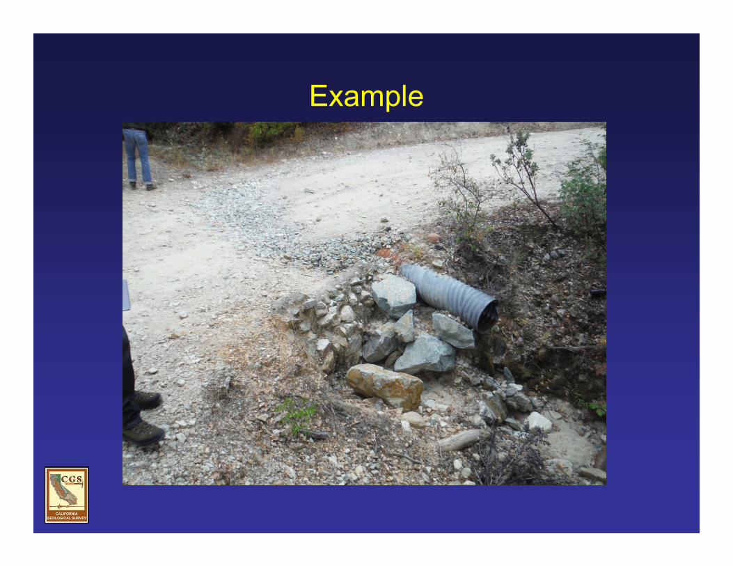
Example


Summary• Use the risk matrix to determine the degree to which crossings are
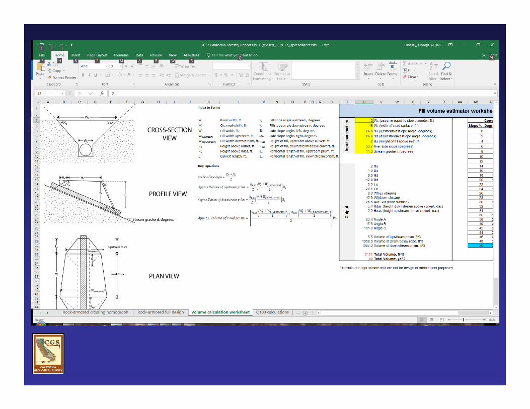
designed and constructed.• Consider the factors discussed regarding bridge design. • Consider the use of available tools (spreadsheet and nomograph) to
design rock-armored crossings to accommodate the estimated 100-year flood flow, including debris and sediment loads.
• Feel free to propose and justify alternatives to the suggested design guidelines.
• If in doubt, request assistance from outside licensed professionals or review team agency personnel (CGS, WQ, CFW).

Thank You!
Questions?