introduction to the high bandwidth transverse feedback w. hofle on behalf of hbtfb team proposed new...
TRANSCRIPT

Introduction to the High Bandwidth Transverse Feedback
W. Hofle
on behalf of HBTFB Team
• Proposed New System vs. Existing Feedback System• Brief History of the Project• Approach for Implementation

HBTFB - High Bandwidth Transverse Feedback
• Wideband feedback system (GHz bandwidth) for SPS• Intra-bunch GHz transverse feedback system• Help stabilize beam against Ecloud and TMCI effects• Under development with LARP
supported by: US-LARP (SLAC, LBNL)LNF-INFN (kicker study)CERN SPS LIU Project
AnalogFrontEnd
Analog BackEnd
SignalProcessing
BPM Kicker
Power AmpADC DAC
Beam Active closed loop GHz Feedback
transverse position
pre-processed sampledposition“slices”
calculatedcorrection data
correctionsignal
pre-distortion drive signal

Existing SPS Transverse Feedback System
operates between lowest betatron frequency and 20 MHz (V & H plane)
handles large injection errors of the order of several mm
Tetrode amplifiers with two tubes drives kicker plates in push-pull configuration (upgrades in 2001)
200 W drive power per tetrode 3 kHz to 20 MHz installed on surface
Tetrode amplifier installed in tunnel under kicker tanks
2 vertical kickers @ b=42 meach 1536 mm long, 38 mm gap
Tunnel with kicker tank and tetrode amplifier in LSS2

Existing Transverse Feedback System
kicker effective capacitance:Cg+2Cp = 122 pF
not all circuit elements shown, e.g. matching at input
200 W drive power in 50 W
3 dB @ 4.5 MHzRA = 180 W, Ceff = 200 pF
Tube: RS 2048-CJC orTH561, max current 15A to 16Aclass AB
operational RF voltage 2.6 kVPhase corrected 20 MHz
4.6 kV4.6 kV
RA=180
kicker 45p
32p 32pRA=180
L L
f < 25 MHzseries resonancewith L at 37 MHz

Existing Feedback: Kick Strength
+/- 2.6 kV @ 100 kHz, L=1536 mm, gap d=38 mm
15)-HFSS from(exact kV 215 2 d
LVV
Vs/m 102.7/ 4 eceVp
+/- 1.83 kV @ 4.5 MHz
kV 152V
Vs/m 100.5 4 ep
kV 46V
Vs/m 1058.1 4 ep
+/- 0.572 kV @ 20 MHz
damps ~5 mm injection error (b=100 m) at 26 GeV/c in 20 turns (gain=0.1)
• 26 GeV/c: kick per turn 8.3 mrad ( 0.54 mm at b=100 m) • regularly running at 0.5 ms damping time (20 turns) • resistive wall growth rate for lowest mode: 0.5 ms to 1 ms
G. Kotzian
integrated kick strength over the entire structure 41.375 V (transverse) for +/-1 V on kicker plates

Comparison of Feedbacks
BA2 Damper (only V-plane discussed)
• detects center of mass oscillations of bunches, feedback in “base-band”• performance improving consolidation under way:
- dedicated new standard SPS pick-ups (BPCR coupler)- updates for single bunch operation, Q20 and bunchlet scrubbing beam
• kHz to 20 MHz, high kick strength (good for mm’s of oscillation)• 7.2x10⁻⁴ eVs/m (100 kHz) to 1.58x10⁻⁴ eVs/m (20 MHz) corresponding to 215 kV
to 46 kV
BA3 Proposed High Bandwidth Feedback (V-plane)
• New approach: Intra-Bunch System similar to stochastic cooling in some way• advanced Digital Technology 4-8 GS/s • ~10 MHz to >~ 1 GHz, not so high kick strength• 10-5 eVs/m to 10-4 eVs/m [3 kV to 30 kV], may need several kickers (4x [2x5kW])• low noise receiver, efficient closed orbit rejection• rejection of noise by processing extremely important (“processing gain”)

Power Requirements - New Feedback System
Injection
• assume only dipolar error at injection (handled by existing feedback)• instabilities kick in rapidly, but intra-bunch motion grows from noise• noise floor and processing gain main ingredients for estimation of power
Performance for given power
• 30 kV transverse volts kick strength at b=60 m 1.15 mrad at 26 GeV/c, kick corresponds to 90 mm at b=100 m at 450 GeV/c: 5 mmassume gain of 0.2 (damping time 10 turns) saturation at 450 GeV/c at 25 mm
• requires 4 kickers of 1 m (see J.Cesaratto) with ~2x5 kW each• start with 1 kicker: saturation at 26 GeV/c: 34 mm at 2x500 W• reasonable approach for next stage design 1 kicker with 3 kV transverse
kick for 26 GeV/c with 2x500 W; foresee higher power handling capability ?
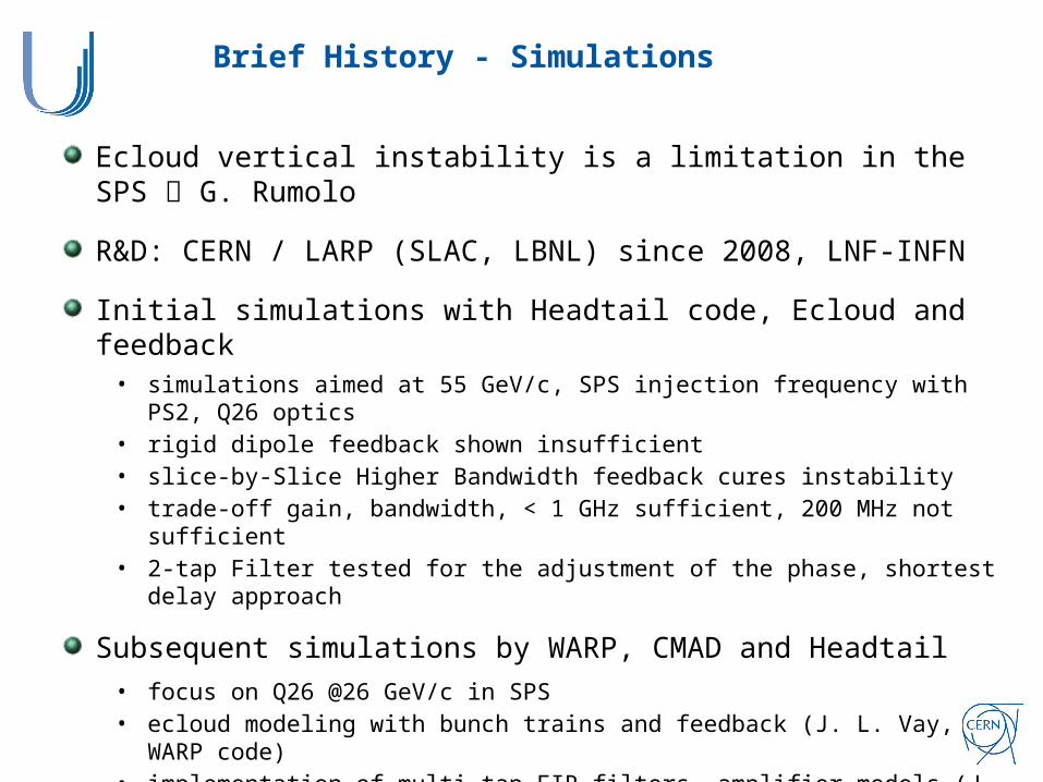
Brief History - Simulations
Ecloud vertical instability is a limitation in the SPS G. Rumolo
R&D: CERN / LARP (SLAC, LBNL) since 2008, LNF-INFN
Initial simulations with Headtail code, Ecloud and feedback• simulations aimed at 55 GeV/c, SPS injection frequency with PS2, Q26 optics• rigid dipole feedback shown insufficient• slice-by-Slice Higher Bandwidth feedback cures instability• trade-off gain, bandwidth, < 1 GHz sufficient, 200 MHz not sufficient• 2-tap Filter tested for the adjustment of the phase, shortest delay approach
Subsequent simulations by WARP, CMAD and Headtail
• focus on Q26 @26 GeV/c in SPS• ecloud modeling with bunch trains and feedback (J. L. Vay, WARP code)• implementation of multi-tap FIR filters, amplifier models (J. Fox, M. Pivi, C. Rivetta,
R. Secondo et al.)• fitting of data with reduced models for controller design (C. Rivetta O. Turgut et al.)• TMCI and switch to Q20 optics (Headtail, K. Li et al.)

Brief History – MD Program, Technology and Approach for Implementation
Initial MDs • understanding of intra-bunch motion and instrumentation (BPWA pick-ups, R. de
Maria et al.)• refurbishment for precision measurements (hybrids, cables, loads, U. Wehrle)• 25 ns and single bunch, concentrate on single bunch MDs (more MD time available)
Single Bunch demonstrator (SLAC) developed for 2012 MDs
• 4 x 100 W amplifiers on a BPWA PU used as kicker, ~0.5% of existing damper• ADC, DAC @3.2 GS/s - 4 GS/s, FPGA processing for single bunch (J. Dusatko et al.)• phase compensation (K. Pollack et al.)• goal: demonstrate damping on a single bunch • Main limitation: 200 MHz bandwidth limit from kicker (length of strip-line)
Future options with demonstrator (between LS1 and LS2)
• extension of demonstrator to bunch trains (LS1) for 48+ bunches• access to full bandwidth of demonstrator only with a new kicker• kicker study also key for use at higher energy (kick strength !)
Full function system commissioning: after LS2
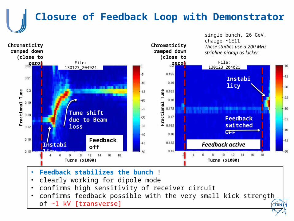
Closure of Feedback Loop with Demonstrator
Tune shift due to Beam loss
InstabilityFeedback off
Feedback active
Instability
single bunch, 26 GeV, charge ~1E11These studies use a 200 MHz stripline pickup as kicker.
Frac
tiona
l Tun
e
Frac
tiona
l Tun
eTurns (x1000) Turns (x1000)
File: 130123_204924 File: 130123_204021
• Feedback stabilizes the bunch !• clearly working for dipole mode• confirms high sensitivity of receiver circuit• confirms feedback possible with the very small kick strength of ~1 kV [transverse]
Feedback switched OFF
Chromaticity ramped down(close to zero)
Chromaticity ramped down(close to zero)

THANK YOU FOR YOUR ATTENTION!
HBTFB Team and current contributorsCERN – H. Bartosik, W. Höfle, G. Iadarola, G. Kotzian, K. Li, E. Montesinos, N. Mounet,
G. Rumolo, B. Salvant, D. Valuch, U. Wehrle, C. ZanniniSLAC – J. Cesaratto, J. Dusatko, J. D. Fox, S. Johnston, J. Olsen, M. Pivi, K. Pollock, C. Rivetta, O. Turgut
LNF-INFN – D. Alesini, A. Drago, S. Gallo, F. Marcellini, M. ZobovLBNL – S. De Santis, Z. Paret, H. Qian
KEK – M. Tobiyama

Selected Bibliography 2009-2013
[1] J. R. Thompson et al., PAC’09, (2009), pp. 4713-4715.
[2] J. D. Fox et al., PAC’09, (2009), pp. 4135-4137.
[3] J.-L. Vay et al., IPAC’10, (2010), pp. 2438-2440.
[4] C. Rivetta et al., PAC’11, (2011), pp. 1621-1623.
[5] R. Secondo et al., IPAC’11, (2011), pp. 1773-1775.
[6] M. Pivi et al., IPAC’12, (2012), pp. 3147-3149.
[7] J. M. Cesaratto et al., IPAC’12, (2012), pp. 112-114.
[8] K. Li et al., IPAC’13, WEPME042, (2013)
[9] J. Dusatko et al., IPAC’13, WEPME059, (2013)
[10] J. D. Fox et al., IPAC’13, WEPME60, (2013)
[11] J. M. Cesaratto et al., IPAC’13, WEPME61, (2013)