introduction to the 8800sx tiles and controls · • two tone sequential • control tone a and...
TRANSCRIPT
Introduction to the 8800SX Tiles and Controls

1 © 2018 VIAVI Solutions Inc. viavisolutions.com
Contents Menu
I/O and Controls Generators Menu Receiver Menu Analyzers Menu Meters Menu Utilities Menu Configuration Menu Options and Accessories External Links
Choose a hyperlink below
Click on the Logo to return to this menu
Click on the shape next to menu items for direct access
External links to related videos: Introducing the 8800 8800 Operating GUI Get the latest Data Sheet 8800SX Data Sheet
2 © 2018 VIAVI Solutions Inc. viavisolutions.com
I/O and Controls Controls and Functions
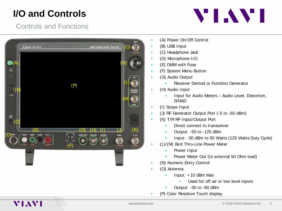
• (A) Power On/Off Control • (B) USB Input • (C) Headphone Jack • (D) Microphone I/O • (E) DMM with Fuse • (F) System Menu Button • (G) Audio Output
• Receiver Demod or Function Generator • (H) Audio Input
• Input for Audio Meters – Audio Level, Distortion, SINAD
• (I) Scope Input • (J) RF Generator Output Port (-5 to -65 dBm) • (K) T/R RF Input/Output Port
• Direct connect to transceiver • Output: -50 to -125 dBm • Input: -30 dBm to 50 Watts (125 Watts Duty Cycle)
• (L)/(M) Bird Thru-Line Power Meter • Power Input • Power Meter Out (to external 50 Ohm load)
• (N) Numeric Entry Control • (O) Antenna
• Input: +10 dBm Max • Used for off air or low level inputs
• Output: -30 to -90 dBm • (P) Color Resistive Touch display
(A)
(C)
(D)
(F)
(G) (H) (I) (J) (K)
(L)
(M)
(B)
(E)
(O)
(N)
(P)
3 © 2018 VIAVI Solutions Inc. viavisolutions.com
I/O and Controls Controls and Functions
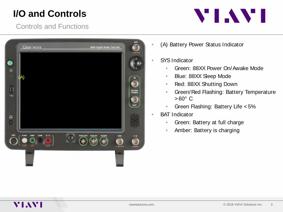
• (A) Battery Power Status Indicator
• SYS Indicator • Green: 88XX Power On/Awake Mode • Blue: 88XX Sleep Mode • Red: 88XX Shutting Down • Green/Red Flashing: Battery Temperature
>60° C • Green Flashing: Battery Life <5%
• BAT Indicator • Green: Battery at full charge • Amber: Battery is charging
(A)
4 © 2018 VIAVI Solutions Inc. viavisolutions.com
I/O and Controls Controls and Functions
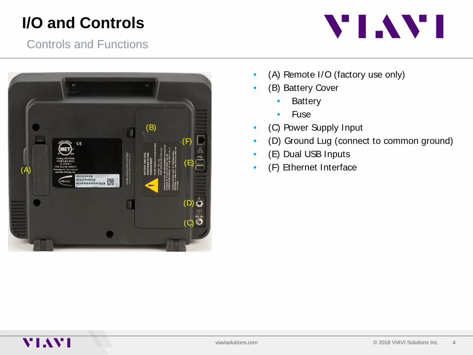
• (A) Remote I/O (factory use only) • (B) Battery Cover
• Battery • Fuse
• (C) Power Supply Input • (D) Ground Lug (connect to common ground) • (E) Dual USB Inputs • (F) Ethernet Interface (A)
(C)
(D)
(F)
(B)
(E)
5 © 2018 VIAVI Solutions Inc. viavisolutions.com
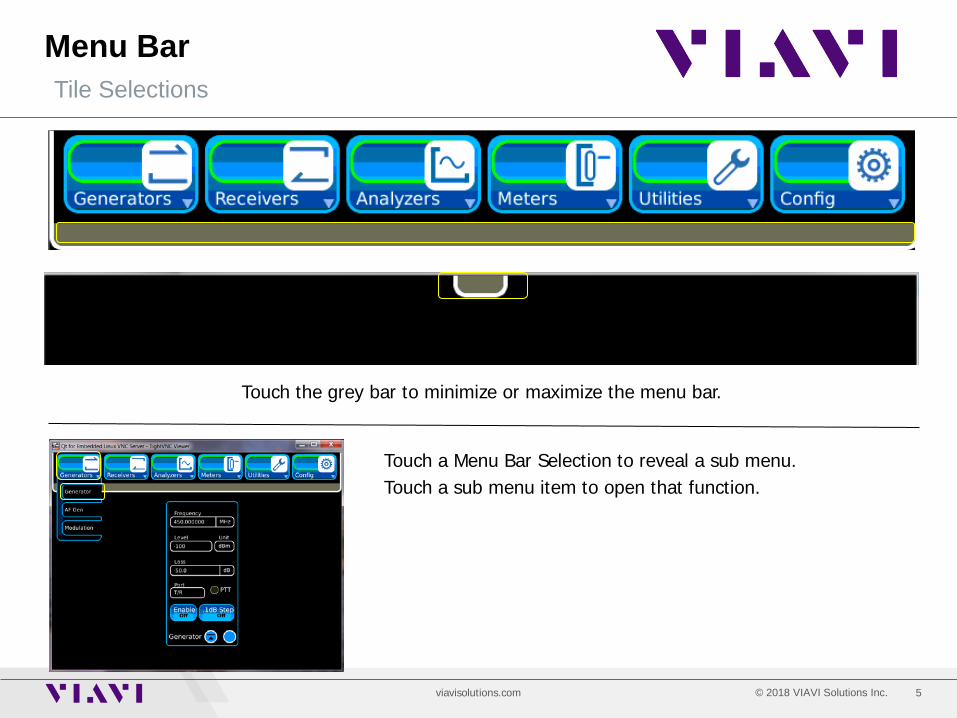
Menu Bar Tile Selections
Touch the grey bar to minimize or maximize the menu bar.
Touch a Menu Bar Selection to reveal a sub menu. Touch a sub menu item to open that function.
6 © 2018 VIAVI Solutions Inc. viavisolutions.com
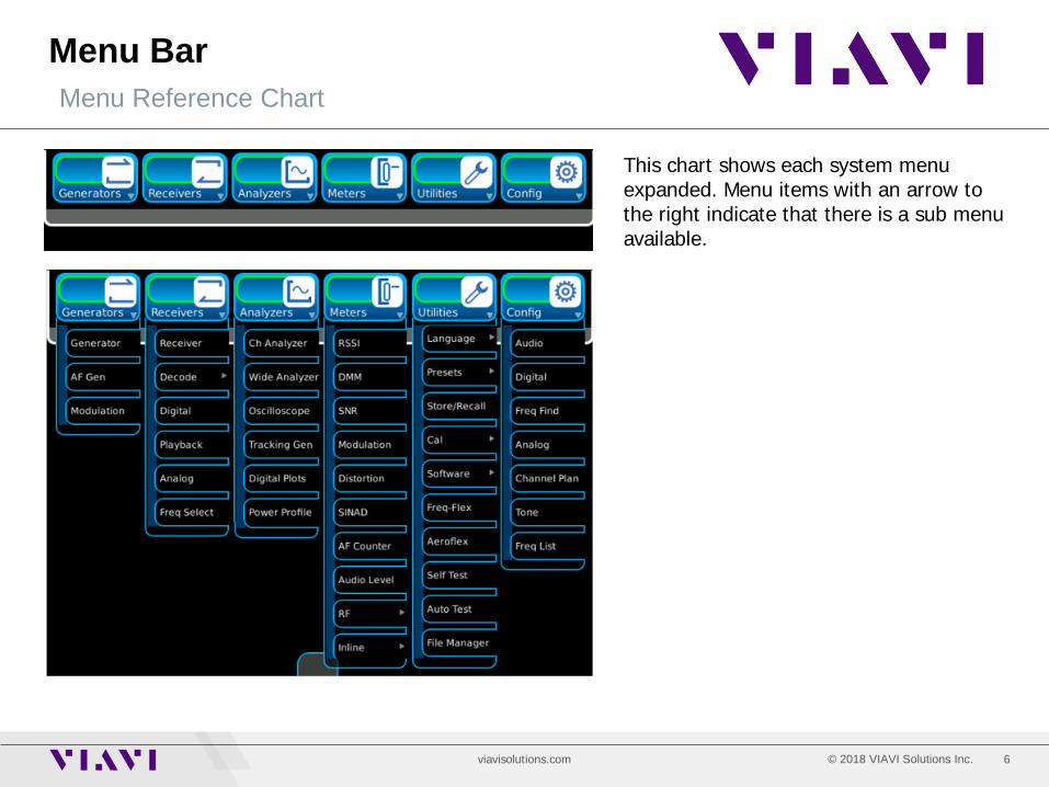
Menu Bar Menu Reference Chart
This chart shows each system menu expanded. Menu items with an arrow to the right indicate that there is a sub menu available.
7 © 2018 VIAVI Solutions Inc. viavisolutions.com
System Menu Controls and Functions
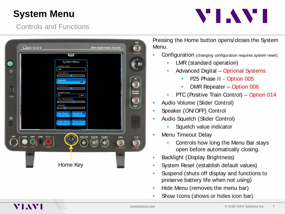
Home Key
Pressing the Home button opens/closes the System Menu. • Configuration (changing configuration requires system reset).
• LMR (standard operation) • Advanced Digital – Optional Systems
• P25 Phase II - Option 005 • DMR Repeater – Option 006
• PTC (Positive Train Control) – Option 014 • Audio Volume (Slider Control) • Speaker (ON/OFF) Control • Audio Squelch (Slider Control)
• Squelch value indicator • Menu Timeout Delay
• Controls how long the Menu Bar stays open before automatically closing.
• Backlight (Display Brightness) • System Reset (establish default values) • Suspend (shuts off display and functions to
preserve battery life when not using) • Hide Menu (removes the menu bar) • Show Icons (shows or hides icon bar)
8 © 2018 VIAVI Solutions Inc. viavisolutions.com
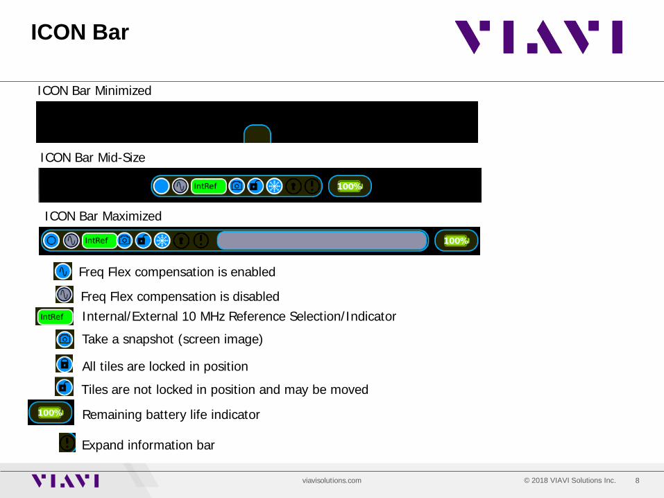
ICON Bar
ICON Bar Minimized
ICON Bar Maximized
ICON Bar Mid-Size
Freq Flex compensation is enabled
Freq Flex compensation is disabled
Take a snapshot (screen image)
All tiles are locked in position
Tiles are not locked in position and may be moved
Remaining battery life indicator
Expand information bar
Internal/External 10 MHz Reference Selection/Indicator

9 © 2018 VIAVI Solutions Inc. viavisolutions.com
Generators Menu Selecting the RF Generator Tile
9
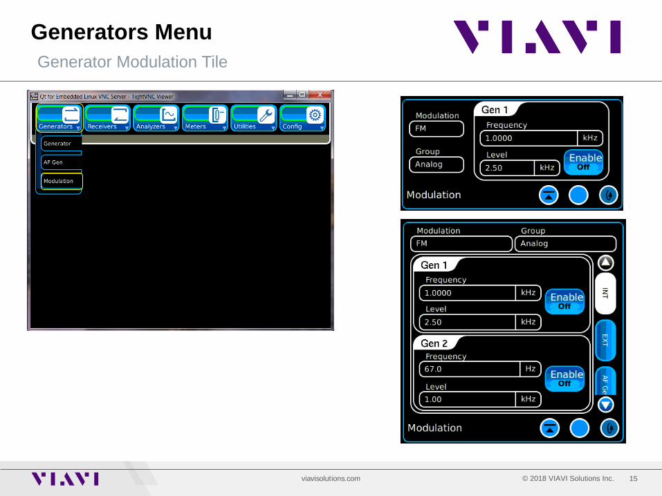
• Expand the menu bar if minimized • Touch the Generators Menu item • Touch the Generator Menu selection
• The Generators Menu allows access to:
• RF Generator controls • AF Generator controls • RF Generator Modulation controls
10 © 2018 VIAVI Solutions Inc. viavisolutions.com
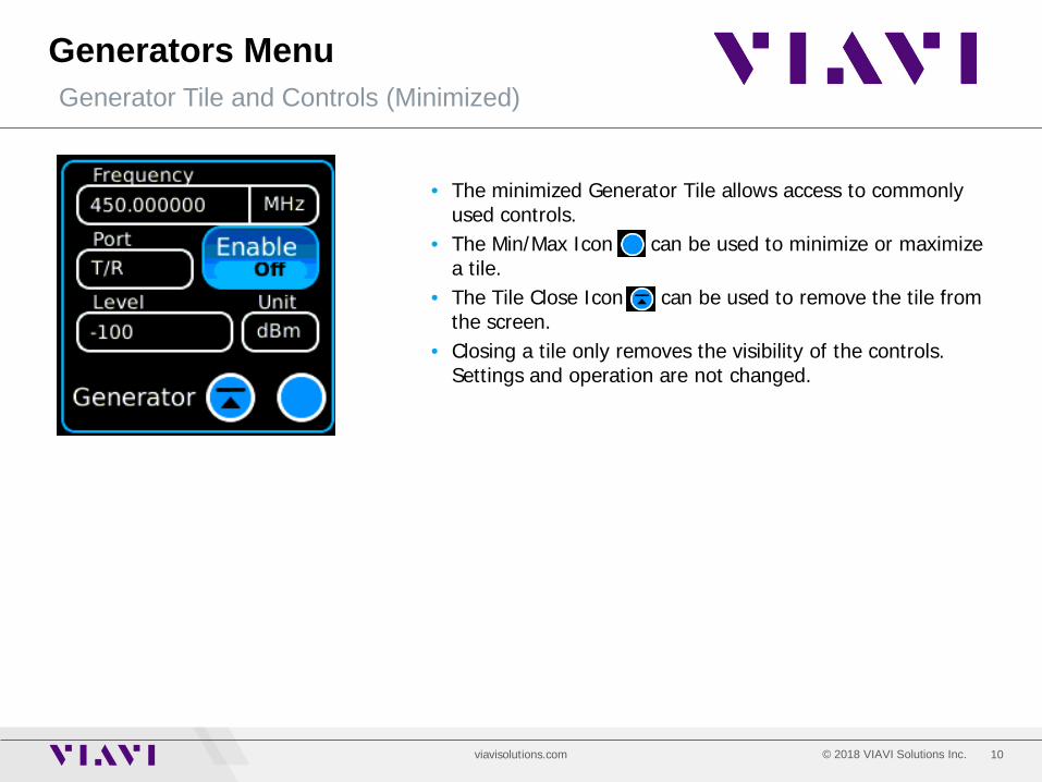
Generators Menu Generator Tile and Controls (Minimized)
• The minimized Generator Tile allows access to commonly used controls.
• The Min/Max Icon can be used to minimize or maximize a tile.
• The Tile Close Icon can be used to remove the tile from the screen.
• Closing a tile only removes the visibility of the controls. Settings and operation are not changed.
11 © 2018 VIAVI Solutions Inc. viavisolutions.com
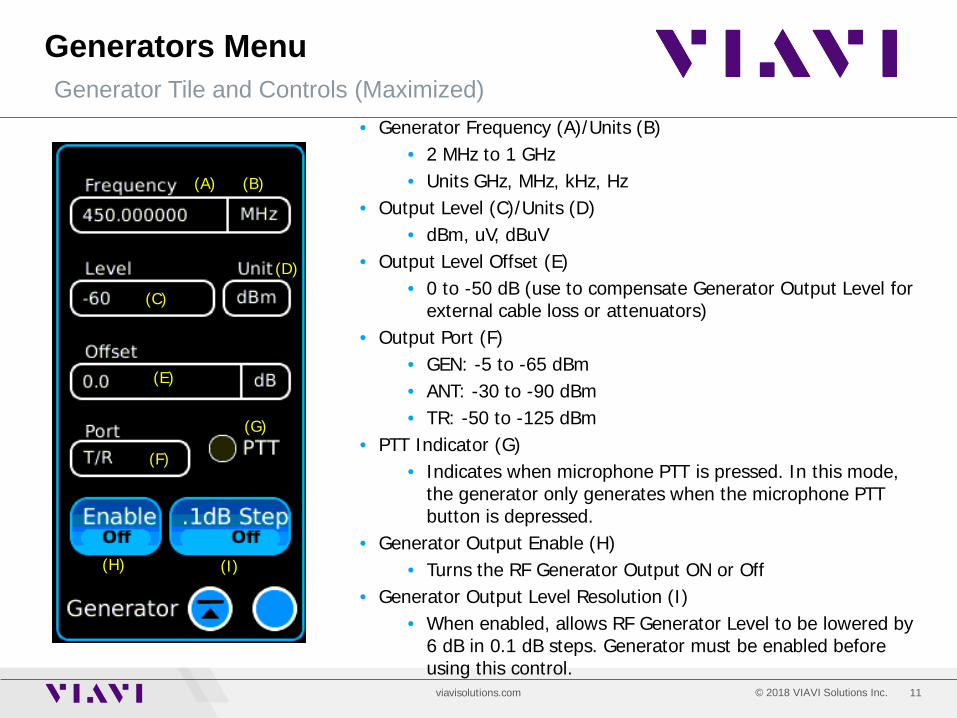
Generators Menu Generator Tile and Controls (Maximized)
(A) (B)
(C)
(E)
(D)
(F)
(G)
(H) (I)
• Generator Frequency (A)/Units (B) • 2 MHz to 1 GHz • Units GHz, MHz, kHz, Hz
• Output Level (C)/Units (D) • dBm, uV, dBuV
• Output Level Offset (E) • 0 to -50 dB (use to compensate Generator Output Level for
external cable loss or attenuators) • Output Port (F)
• GEN: -5 to -65 dBm • ANT: -30 to -90 dBm • TR: -50 to -125 dBm
• PTT Indicator (G) • Indicates when microphone PTT is pressed. In this mode,
the generator only generates when the microphone PTT button is depressed.
• Generator Output Enable (H) • Turns the RF Generator Output ON or Off
• Generator Output Level Resolution (I) • When enabled, allows RF Generator Level to be lowered by
6 dB in 0.1 dB steps. Generator must be enabled before using this control.
12 © 2018 VIAVI Solutions Inc. viavisolutions.com
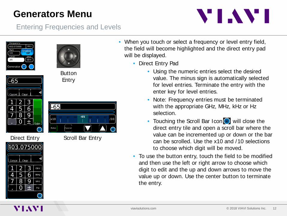
Generators Menu Entering Frequencies and Levels
• When you touch or select a frequency or level entry field, the field will become highlighted and the direct entry pad will be displayed.
• Direct Entry Pad • Using the numeric entries select the desired
value. The minus sign is automatically selected for level entries. Terminate the entry with the enter key for level entries.
• Note: Frequency entries must be terminated with the appropriate GHz, MHz, kHz or Hz selection.
• Touching the Scroll Bar Icon will close the direct entry tile and open a scroll bar where the value can be incremented up or down or the bar can be scrolled. Use the x10 and /10 selections to choose which digit will be moved.
• To use the button entry, touch the field to be modified and then use the left or right arrow to choose which digit to edit and the up and down arrows to move the value up or down. Use the center button to terminate the entry.
Scroll Bar Entry Direct Entry
Button Entry

13 © 2018 VIAVI Solutions Inc. viavisolutions.com
Generators Menu AF Generator Controls
AF Generator Minimized
AF Generator Maximized
The Fast Stack Icon can be used to stack tiles on top of each other and quickly access the one that is beneath. It acts as a “Send to Back” feature. Very useful to have many instruments readily available.
14 © 2018 VIAVI Solutions Inc. viavisolutions.com
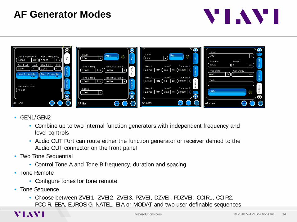
AF Generator Modes
• GEN1/GEN2 • Combine up to two internal function generators with independent frequency and
level controls • Audio OUT Port can route either the function generator or receiver demod to the
Audio OUT connector on the front panel • Two Tone Sequential
• Control Tone A and Tone B frequency, duration and spacing • Tone Remote
• Configure tones for tone remote • Tone Sequence
• Choose between ZVEI1, ZVEI2, ZVEI3, PZVEI, DZVEI, PDZVEI, CCIR1, CCIR2, PCCIR, EEA, EUROSIG, NATEL, EIA or MODAT and two user definable sequences
15 © 2018 VIAVI Solutions Inc. viavisolutions.com
Generators Menu Generator Modulation Tile
16 © 2018 VIAVI Solutions Inc. viavisolutions.com
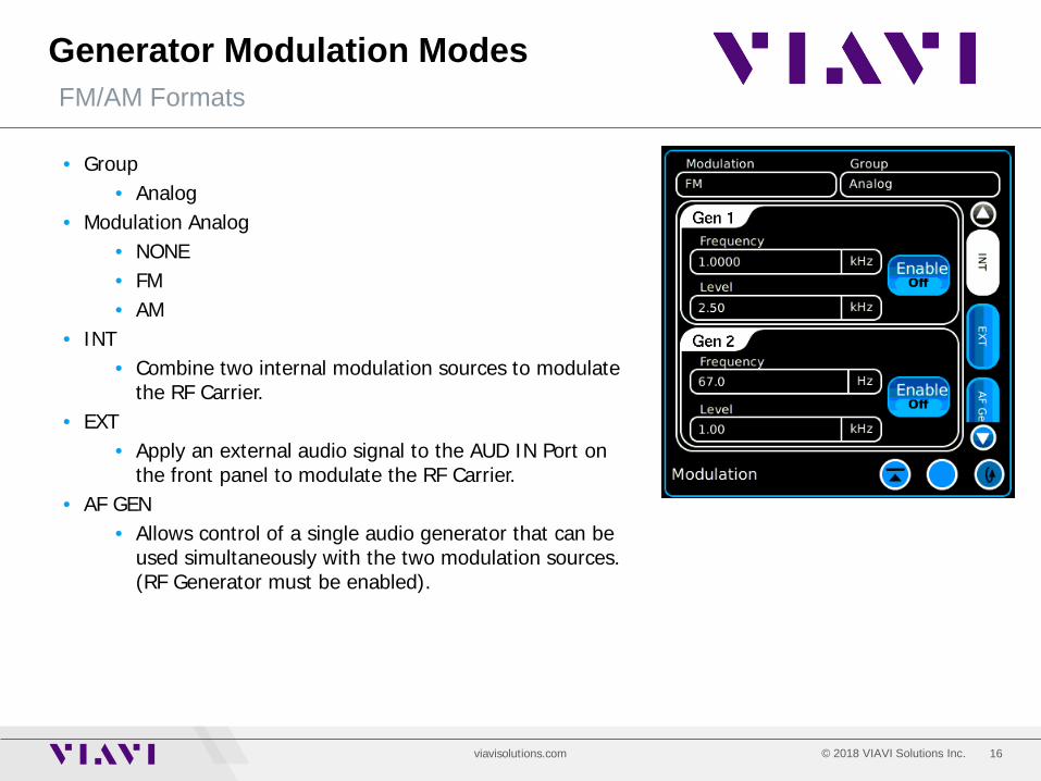
Generator Modulation Modes FM/AM Formats
• Group • Analog
• Modulation Analog • NONE • FM • AM
• INT • Combine two internal modulation sources to modulate
the RF Carrier. • EXT
• Apply an external audio signal to the AUD IN Port on the front panel to modulate the RF Carrier.
• AF GEN • Allows control of a single audio generator that can be
used simultaneously with the two modulation sources. (RF Generator must be enabled).
17 © 2018 VIAVI Solutions Inc. viavisolutions.com
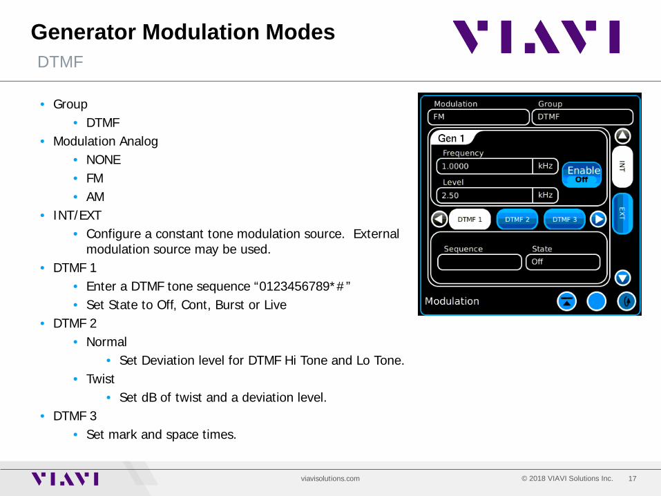
Generator Modulation Modes DTMF
• Group • DTMF
• Modulation Analog • NONE • FM • AM
• INT/EXT • Configure a constant tone modulation source. External
modulation source may be used. • DTMF 1
• Enter a DTMF tone sequence “0123456789*#” • Set State to Off, Cont, Burst or Live
• DTMF 2 • Normal
• Set Deviation level for DTMF Hi Tone and Lo Tone. • Twist
• Set dB of twist and a deviation level. • DTMF 3
• Set mark and space times.
18 © 2018 VIAVI Solutions Inc. viavisolutions.com
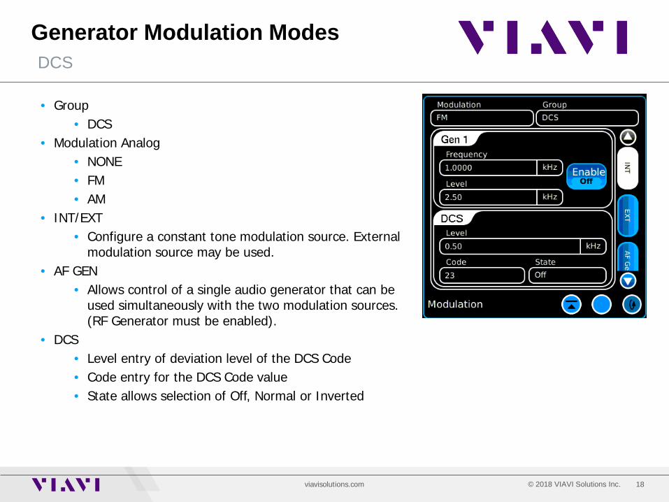
Generator Modulation Modes DCS
• Group • DCS
• Modulation Analog • NONE • FM • AM
• INT/EXT • Configure a constant tone modulation source. External
modulation source may be used. • AF GEN
• Allows control of a single audio generator that can be used simultaneously with the two modulation sources. (RF Generator must be enabled).
• DCS • Level entry of deviation level of the DCS Code • Code entry for the DCS Code value • State allows selection of Off, Normal or Inverted
19 © 2018 VIAVI Solutions Inc. viavisolutions.com
Generator Modulation Modes Two Tone, Tone Remote and Tone Sequence
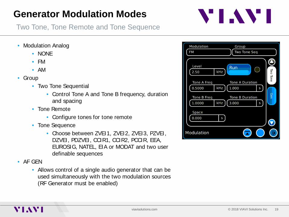
• Modulation Analog • NONE • FM • AM
• Group • Two Tone Sequential
• Control Tone A and Tone B frequency, duration and spacing
• Tone Remote • Configure tones for tone remote
• Tone Sequence • Choose between ZVEI1, ZVEI2, ZVEI3, PZVEI,
DZVEI, PDZVEI, CCIR1, CCIR2, PCCIR, EEA, EUROSIG, NATEL, EIA or MODAT and two user definable sequences
• AF GEN • Allows control of a single audio generator that can be
used simultaneously with the two modulation sources (RF Generator must be enabled)
20 © 2018 VIAVI Solutions Inc. viavisolutions.com
Receivers Menu Receivers Selector
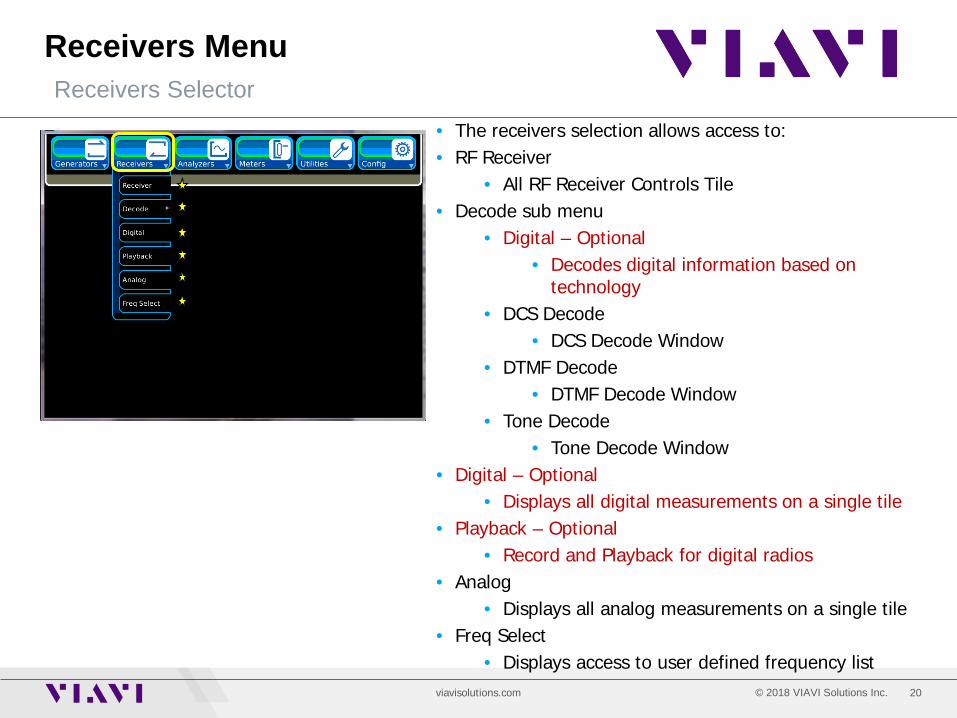
• The receivers selection allows access to: • RF Receiver
• All RF Receiver Controls Tile • Decode sub menu
• Digital – Optional • Decodes digital information based on
technology • DCS Decode
• DCS Decode Window • DTMF Decode
• DTMF Decode Window • Tone Decode
• Tone Decode Window • Digital – Optional
• Displays all digital measurements on a single tile • Playback – Optional
• Record and Playback for digital radios • Analog
• Displays all analog measurements on a single tile • Freq Select
• Displays access to user defined frequency list

21 © 2018 VIAVI Solutions Inc. viavisolutions.com
Receivers Menu Receiver Tile and Controls (Maximized)
(A)
(B)
(C) (E)
(D)
(F) (G)
(H) (I)
• Receiver Frequency (A)/Units (B) • 2 MHz to 1 GHz • Units GHz, MHz, kHz, Hz
• Generator Offset (C)/Units (D) • RF Signal Generator Frequency Offset • dBm, uV, dBuV
• Lock (E) • On: Generator frequency will be offset from the receiver • Off: The Generator frequency is unlocked from the receiver
• Demod (F) • FM, AM, Options - P25, DMR, dPMR, ARIB T98, NXDN
• IF BW (G) • 5 kHz, 6.25 kHz, 8.33 kHz, 10 kHz, 12.5 kHz, 25 kHz, 30
kHz, 100 kHz, 300 kHz • RF Input Port (H)
• ANT: +10 dBm Max • TR: 50 Watts cont./125 Watts Duty Cycled
(J) (K)
(L) (M)
22 © 2018 VIAVI Solutions Inc. viavisolutions.com
Receivers Menu Receiver Tile and Controls (Maximized)
(A)
(B)
(C) (E)
(D)
(F) (G)
(H) (I)
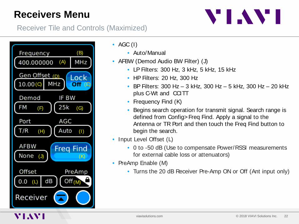
• AGC (I) • Auto/Manual
• AFBW (Demod Audio BW Filter) (J) • LP Filters: 300 Hz, 3 kHz, 5 kHz, 15 kHz • HP Filters: 20 Hz, 300 Hz • BP Filters: 300 Hz – 3 kHz, 300 Hz – 5 kHz, 300 Hz – 20 kHz
plus C-Wt and CCITT • Frequency Find (K) • Begins search operation for transmit signal. Search range is
defined from Config>Freq Find. Apply a signal to the Antenna or TR Port and then touch the Freq Find button to begin the search.
• Input Level Offset (L) • 0 to -50 dB (Use to compensate Power/RSSI measurements
for external cable loss or attenuators) • PreAmp Enable (M)
• Turns the 20 dB Receiver Pre-Amp ON or Off (Ant input only)
(J) (K)
(L) (M)
23 © 2018 VIAVI Solutions Inc. viavisolutions.com
Receiver Menu Receiver Tile and Controls (Minimized)
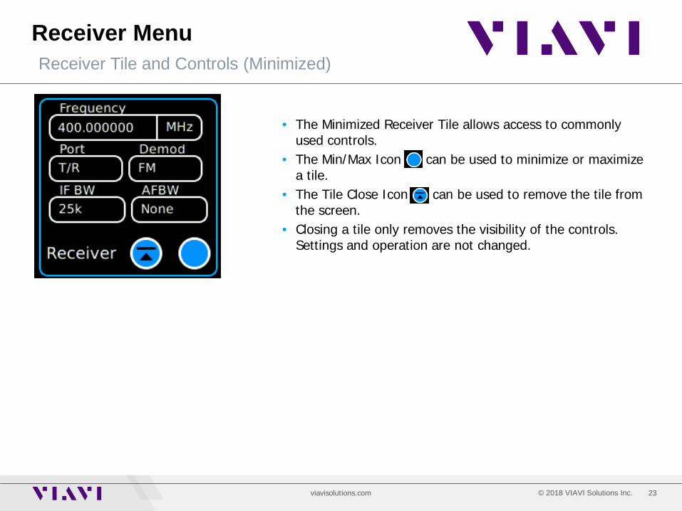
• The Minimized Receiver Tile allows access to commonly used controls.
• The Min/Max Icon can be used to minimize or maximize a tile.
• The Tile Close Icon can be used to remove the tile from the screen.
• Closing a tile only removes the visibility of the controls. Settings and operation are not changed.
24 © 2018 VIAVI Solutions Inc. viavisolutions.com
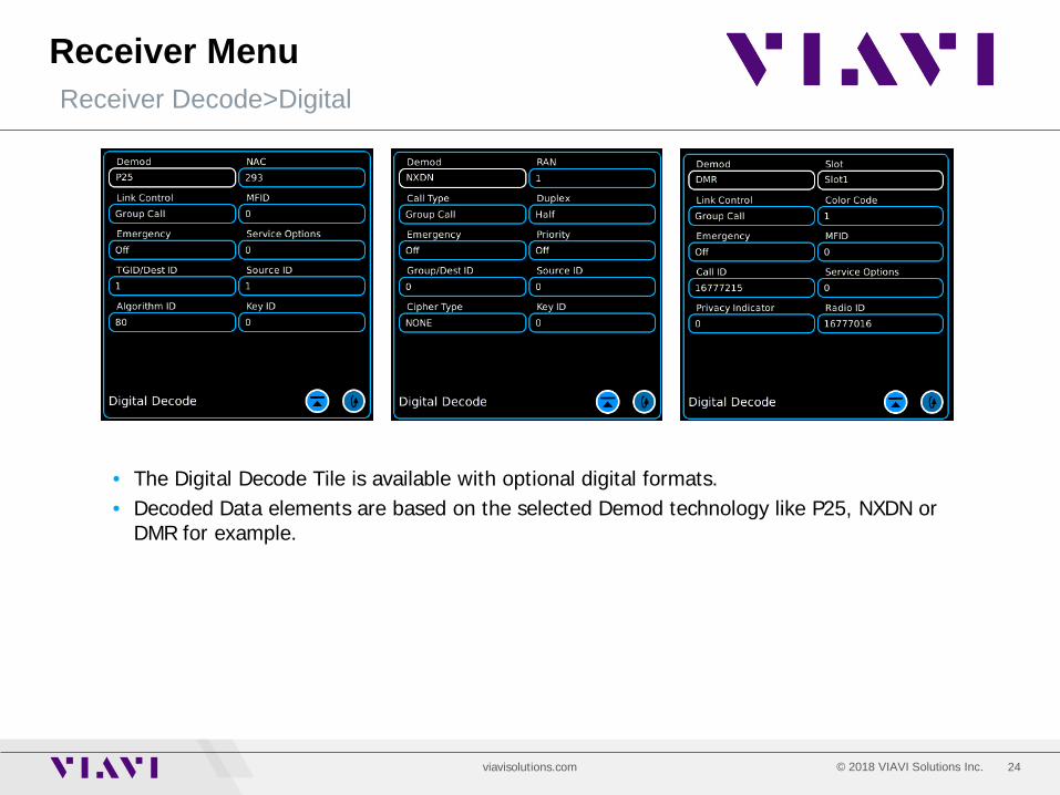
Receiver Menu Receiver Decode>Digital
• The Digital Decode Tile is available with optional digital formats. • Decoded Data elements are based on the selected Demod technology like P25, NXDN or
DMR for example.
25 © 2018 VIAVI Solutions Inc. viavisolutions.com
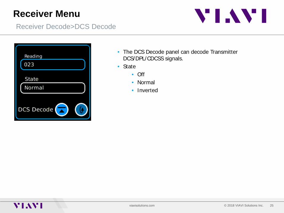
Receiver Menu Receiver Decode>DCS Decode
• The DCS Decode panel can decode Transmitter DCS/DPL/CDCSS signals.
• State • Off • Normal • Inverted
26 © 2018 VIAVI Solutions Inc. viavisolutions.com
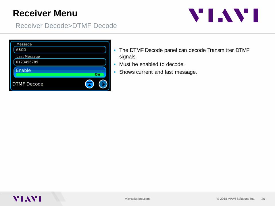
Receiver Menu Receiver Decode>DTMF Decode
• The DTMF Decode panel can decode Transmitter DTMF signals.
• Must be enabled to decode. • Shows current and last message.
27 © 2018 VIAVI Solutions Inc. viavisolutions.com
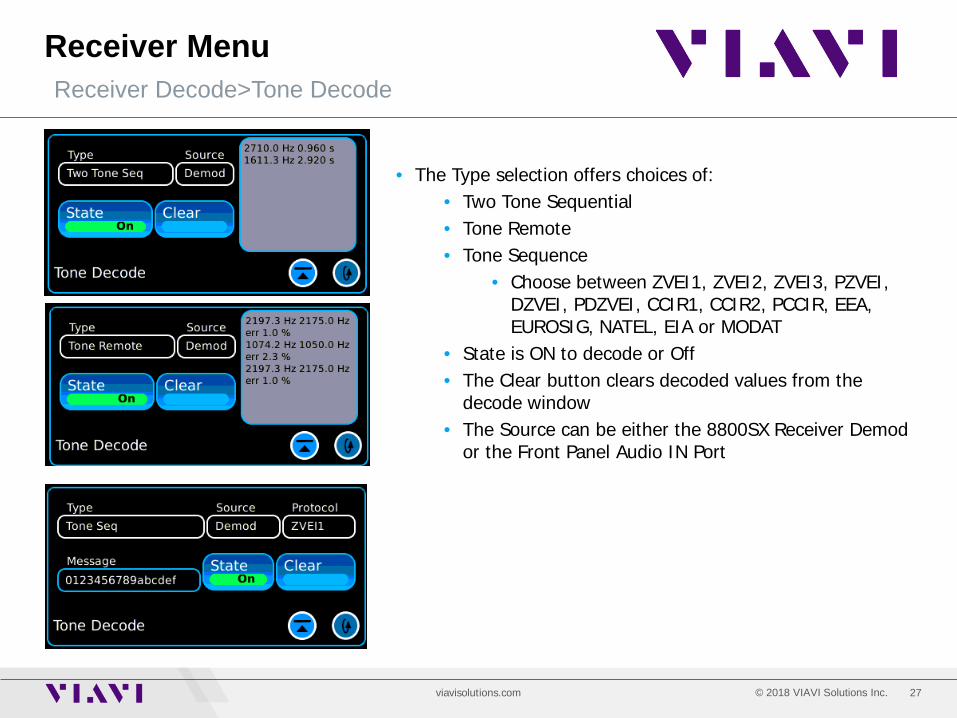
Receiver Menu Receiver Decode>Tone Decode
• The Type selection offers choices of: • Two Tone Sequential • Tone Remote • Tone Sequence
• Choose between ZVEI1, ZVEI2, ZVEI3, PZVEI, DZVEI, PDZVEI, CCIR1, CCIR2, PCCIR, EEA, EUROSIG, NATEL, EIA or MODAT
• State is ON to decode or Off • The Clear button clears decoded values from the
decode window • The Source can be either the 8800SX Receiver Demod
or the Front Panel Audio IN Port

28 © 2018 VIAVI Solutions Inc. viavisolutions.com
Receiver Menu Receiver Digital
• For Optional digital systems like P25, NXDN, DMR etc. the Digital Demod Tile provides all of the necessary measurements required to properly evaluate a digital signal.
• Demod Type: P25, DMR, dPMR, ARIBT98, NXDN • RF Frequency Error • Signal Power/Slot Power for TDMA Signals • Broadband Power • TX BER
• BER Patterns are available • P25 – 1011, CAL, O.153, FRAMESYNC • NXDN – 1031, CAL, O.153, FSW+PN9,
FRAMESYNC • DMR – 1031, CAL, O.153, FRAMESYNC
• Symbol Deviation • Modulation Fidelity/FSK Error • Symbol Clock Error • NAC (P25) • Norm Button: Calibrates the Signal Power Meter • Rest Acquire: Resets the digital readings • Zero RF: Zero’s the RF Power Meter (Broadband)

29 © 2018 VIAVI Solutions Inc. viavisolutions.com
Receiver Menu Receiver Playback
• For Optional digital systems like P25, NXDN, DMR etc. the Record and Playback feature is available.
• Simply Key the Digital Transmitter and press the Record button.
• Begin talking as desired then de-key the transmitter. • The recorded audio will then be played back to the receiver. • The recording is automatically saved and may be played
back as often as desired. • For DMR systems, both simplex and duplex modes are
supported.
30 © 2018 VIAVI Solutions Inc. viavisolutions.com
Receiver Menu Receiver Analog
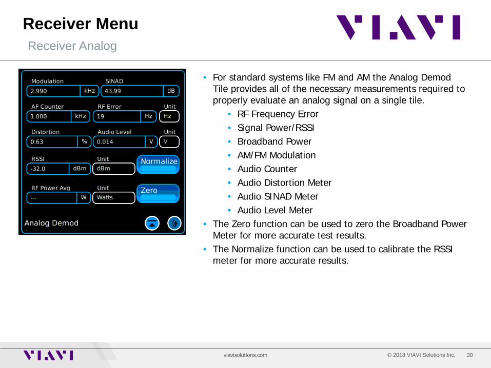
• For standard systems like FM and AM the Analog Demod Tile provides all of the necessary measurements required to properly evaluate an analog signal on a single tile.
• RF Frequency Error • Signal Power/RSSI • Broadband Power • AM/FM Modulation • Audio Counter • Audio Distortion Meter • Audio SINAD Meter • Audio Level Meter
• The Zero function can be used to zero the Broadband Power Meter for more accurate test results.
• The Normalize function can be used to calibrate the RSSI meter for more accurate results.
31 © 2018 VIAVI Solutions Inc. viavisolutions.com
Receiver Menu Receiver Frequency Select
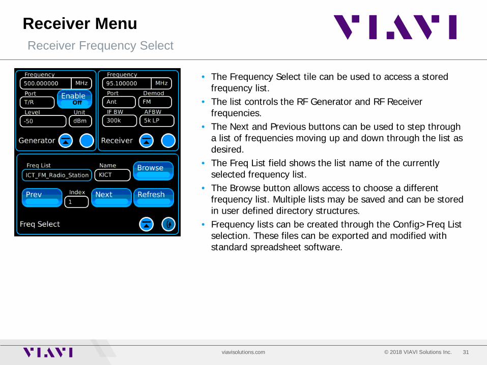
• The Frequency Select tile can be used to access a stored frequency list.
• The list controls the RF Generator and RF Receiver frequencies.
• The Next and Previous buttons can be used to step through a list of frequencies moving up and down through the list as desired.
• The Freq List field shows the list name of the currently selected frequency list.
• The Browse button allows access to choose a different frequency list. Multiple lists may be saved and can be stored in user defined directory structures.
• Frequency lists can be created through the Config>Freq List selection. These files can be exported and modified with standard spreadsheet software.

32 © 2018 VIAVI Solutions Inc. viavisolutions.com
Analyzers Menu Analyzers Selections
• The Analyzers selection allows access to: • Channel Analyzer
• Look and listen up to a 5 MHz span • Wide Analyzer
• Offers spectrum display with spans up to 50 MHz • Oscilloscope
• View audio signals in time domain • Tracking Generator – Option 010
• Sweep Filters • Perform Distance to Fault Plots • Perform Return Loss Sweeps • Perform VSWR Sweeps
• Digital Plots – Included with any digital option • Symbol Distribution • Constellation • Eye Diagram
• Power Profile – Included with DMR option • Shows Power Profile mask limits and pass/fail status
for DMR subscriber power ramps.
33 © 2018 VIAVI Solutions Inc. viavisolutions.com
Analyzers Menu Channel Analyzer
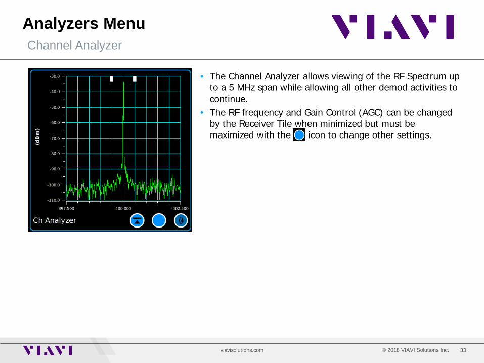
• The Channel Analyzer allows viewing of the RF Spectrum up to a 5 MHz span while allowing all other demod activities to continue.
• The RF frequency and Gain Control (AGC) can be changed by the Receiver Tile when minimized but must be maximized with the icon to change other settings.
34 © 2018 VIAVI Solutions Inc. viavisolutions.com
Analyzers Menu Channel Analyzer - Maximized
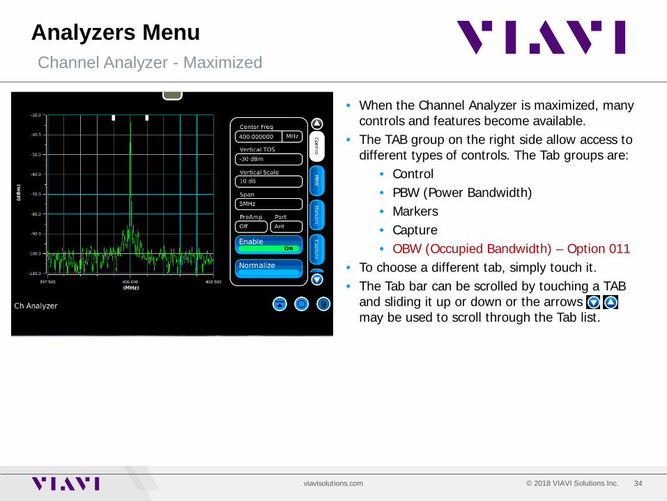
• When the Channel Analyzer is maximized, many controls and features become available.
• The TAB group on the right side allow access to different types of controls. The Tab groups are:
• Control • PBW (Power Bandwidth) • Markers • Capture • OBW (Occupied Bandwidth) – Option 011
• To choose a different tab, simply touch it. • The Tab bar can be scrolled by touching a TAB
and sliding it up or down or the arrows may be used to scroll through the Tab list.

35 © 2018 VIAVI Solutions Inc. viavisolutions.com
Analyzers Menu Channel Analyzer – Maximized – Control Tab
• The Control Tab allows access to the following controls:
• Center Frequency • Vertical Top of Scale • Vertical Scale factor 20, 15, 10, 5, 2
dB/div. • Span 5, 2, 1 MHz, 500, 200, 100 kHz, 50,
20 and 10 kHz • PreAmp control Auto, On, Off
• With a 10 kHz Span and the PreAmp ON, a near -150 dBm noise floor can be seen to look for small signal levels from the ANT Port.
• Enable On/Off. Analyzer stops sweeping when in the Off condition.
• Normalize: Calibrates the RSSI Meter and the vertical scale of the analyzer.
36 © 2018 VIAVI Solutions Inc. viavisolutions.com
Analyzers Menu Channel Analyzer – Maximized – PBW Tab
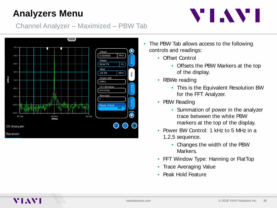
• The PBW Tab allows access to the following controls and readings:
• Offset Control • Offsets the PBW Markers at the top
of the display. • RBWe reading
• This is the Equivalent Resolution BW for the FFT Analyzer.
• PBW Reading • Summation of power in the analyzer
trace between the white PBW markers at the top of the display.
• Power BW Control: 1 kHz to 5 MHz in a 1,2,5 sequence.
• Changes the width of the PBW Markers.
• FFT Window Type: Hanning or FlatTop • Trace Averaging Value • Peak Hold Feature
37 © 2018 VIAVI Solutions Inc. viavisolutions.com
Analyzers Menu Channel Analyzer – Maximized – Markers Tab
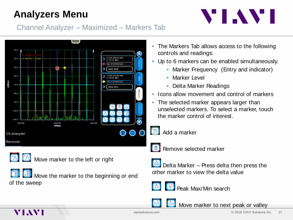
• The Markers Tab allows access to the following controls and readings:
• Up to 6 markers can be enabled simultaneously. • Marker Frequency (Entry and indicator) • Marker Level • Delta Marker Readings
• Icons allow movement and control of markers • The selected marker appears larger than
unselected markers. To select a marker, touch the marker control of interest.
Add a marker Remove selected marker Delta Marker – Press delta then press the other marker to view the delta value Peak Max/Min search Move marker to next peak or valley
Move marker to the left or right Move the marker to the beginning or end of the sweep
38 © 2018 VIAVI Solutions Inc. viavisolutions.com
Analyzers Menu Channel Analyzer – Maximized – Capture Tab
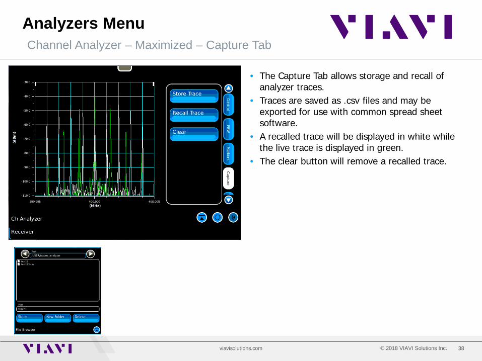
• The Capture Tab allows storage and recall of analyzer traces.
• Traces are saved as .csv files and may be exported for use with common spread sheet software.
• A recalled trace will be displayed in white while the live trace is displayed in green.
• The clear button will remove a recalled trace.

39 © 2018 VIAVI Solutions Inc. viavisolutions.com
Analyzers Menu Channel Analyzer – Maximized – OBW Tab - Optional
• The Optional OBW Tab provides a measurement of a signals power and occupied bandwidth.
• A modulated signal will appear lower on the spectrum analyzer than what its actual power level is.
• Percentile: User entry to define the percent of bandwidth to be displayed by the blue markers. In this case, 99.9% of the RF Energy occupies 10.7812 kHz of this trace display.
• OBW Power: This is the actual RF Energy level that is within the blue markers. In this case, the level is -39.3606 dBm.
• Mode – Live, Peak Hold, Hold • Allows measurement of a static trace or a
peak hold trace. • OBW Enable: Turn this measurement On or Off

40 © 2018 VIAVI Solutions Inc. viavisolutions.com
Analyzers Menu Wideband Analyzer
• The Wideband Analyzer offers all of the same controls as the CH Analyzer with the following exceptions:
• The Wideband Analyzer offers spans up to 50 MHz.
• Demodulated audio may be choppy at spans greater than 5 MHz.
• The AGC operates only in manual mode. • The AGC setting must be manually
adjusted to best match the level of the incoming signal.

41 © 2018 VIAVI Solutions Inc. viavisolutions.com
Analyzers Menu Scope
• The scope allows viewing of audio signals in the time domain.
• To access scope controls, expand or maximize the scope with the icon.
42 © 2018 VIAVI Solutions Inc. viavisolutions.com
Analyzers Menu Scope - Maximized
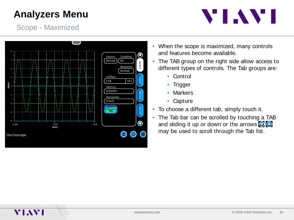
• When the scope is maximized, many controls and features become available.
• The TAB group on the right side allow access to different types of controls. The Tab groups are:
• Control • Trigger • Markers • Capture
• To choose a different tab, simply touch it. • The Tab bar can be scrolled by touching a TAB
and sliding it up or down or the arrows may be used to scroll through the Tab list.
43 © 2018 VIAVI Solutions Inc. viavisolutions.com
Analyzers Menu Scope – Maximized – Control Tab
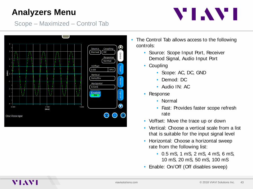
• The Control Tab allows access to the following controls:
• Source: Scope Input Port, Receiver Demod Signal, Audio Input Port
• Coupling • Scope: AC, DC, GND • Demod: DC • Audio IN: AC
• Response • Normal • Fast: Provides faster scope refresh
rate • Voffset: Move the trace up or down • Vertical: Choose a vertical scale from a list
that is suitable for the input signal level • Horizontal: Choose a horizontal sweep
rate from the following list: • 0.5 mS, 1 mS, 2 mS, 4 mS, 6 mS,
10 mS, 20 mS, 50 mS, 100 mS • Enable: On/Off (Off disables sweep)
44 © 2018 VIAVI Solutions Inc. viavisolutions.com
Analyzers Menu Scope – Maximized – Trigger Tab
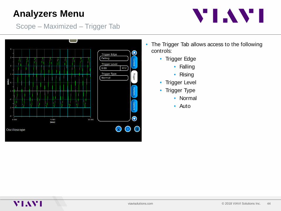
• The Trigger Tab allows access to the following controls:
• Trigger Edge • Falling • Rising
• Trigger Level • Trigger Type
• Normal • Auto
45 © 2018 VIAVI Solutions Inc. viavisolutions.com
Analyzers Menu Scope – Maximized – Markers Tab
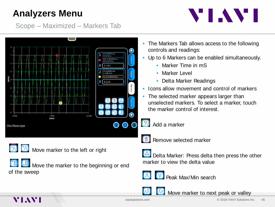
• The Markers Tab allows access to the following controls and readings:
• Up to 6 Markers can be enabled simultaneously. • Marker Time in mS • Marker Level • Delta Marker Readings
• Icons allow movement and control of markers • The selected marker appears larger than
unselected markers. To select a marker, touch the marker control of interest.
Add a marker Remove selected marker Delta Marker: Press delta then press the other marker to view the delta value Peak Max/Min search Move marker to next peak or valley
Move marker to the left or right Move the marker to the beginning or end of the sweep
46 © 2018 VIAVI Solutions Inc. viavisolutions.com
Analyzers Menu Scope – Maximized – Capture Tab
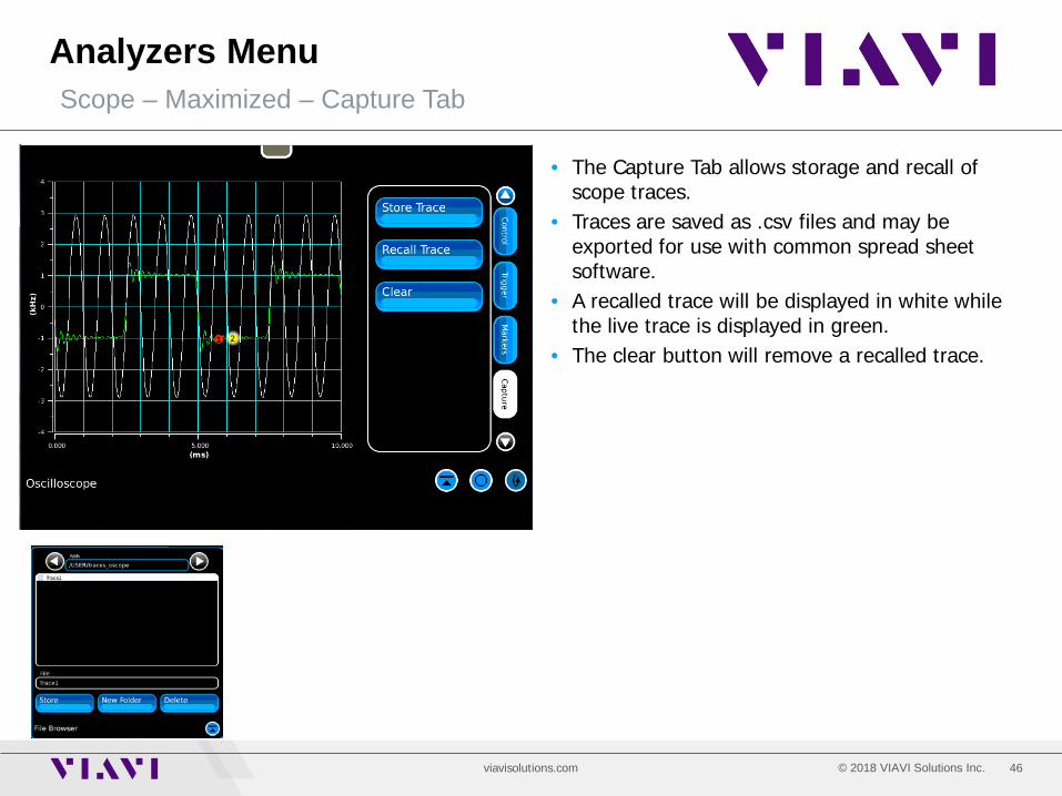
• The Capture Tab allows storage and recall of scope traces.
• Traces are saved as .csv files and may be exported for use with common spread sheet software.
• A recalled trace will be displayed in white while the live trace is displayed in green.
• The clear button will remove a recalled trace.
47 © 2018 VIAVI Solutions Inc. viavisolutions.com
Analyzers Menu Tracking Generator – Maximized Only – Option 010
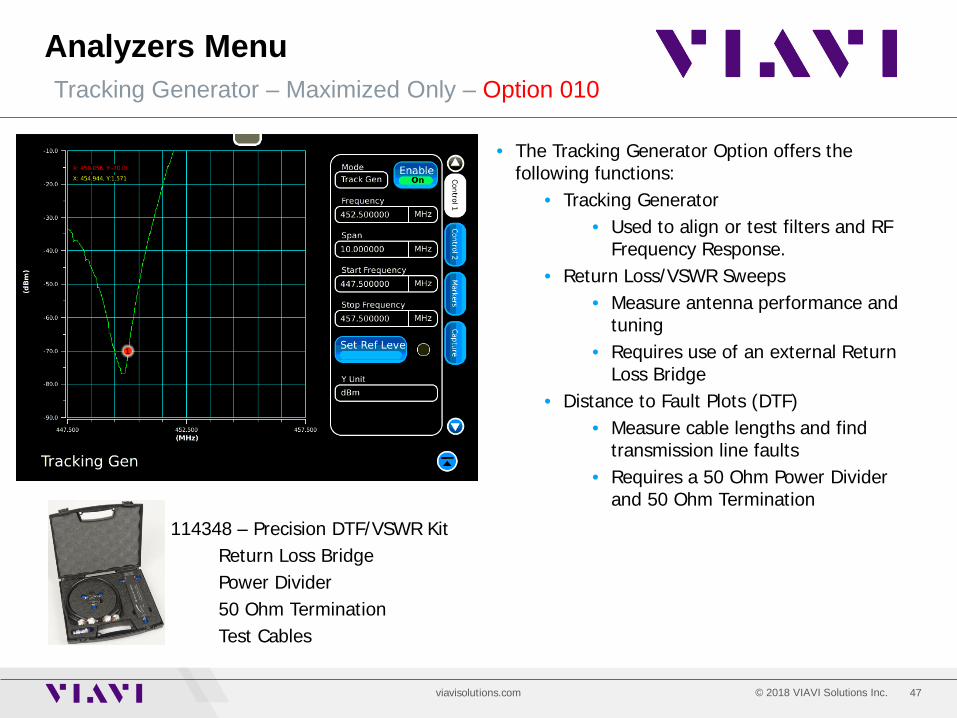
• The Tracking Generator Option offers the following functions:
• Tracking Generator • Used to align or test filters and RF
Frequency Response. • Return Loss/VSWR Sweeps
• Measure antenna performance and tuning
• Requires use of an external Return Loss Bridge
• Distance to Fault Plots (DTF) • Measure cable lengths and find
transmission line faults • Requires a 50 Ohm Power Divider
and 50 Ohm Termination 114348 – Precision DTF/VSWR Kit
Return Loss Bridge Power Divider 50 Ohm Termination Test Cables
48 © 2018 VIAVI Solutions Inc. viavisolutions.com
Analyzers Menu Tracking Generator – Maximized Only – Option 010
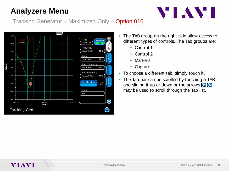
• The TAB group on the right side allow access to different types of controls. The Tab groups are:
• Control 1 • Control 2 • Markers • Capture
• To choose a different tab, simply touch it. • The Tab bar can be scrolled by touching a TAB
and sliding it up or down or the arrows may be used to scroll through the Tab list.
49 © 2018 VIAVI Solutions Inc. viavisolutions.com
Analyzers Menu Tracking Generator – Control 1 Tab
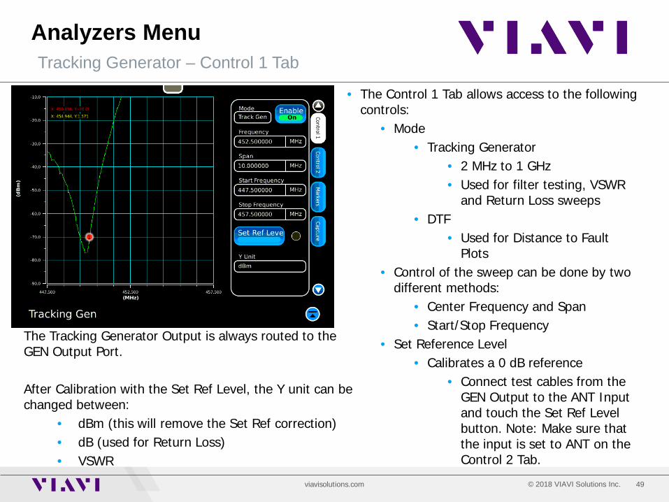
• The Control 1 Tab allows access to the following controls:
• Mode • Tracking Generator
• 2 MHz to 1 GHz • Used for filter testing, VSWR
and Return Loss sweeps • DTF
• Used for Distance to Fault Plots
• Control of the sweep can be done by two different methods:
• Center Frequency and Span • Start/Stop Frequency
• Set Reference Level • Calibrates a 0 dB reference
• Connect test cables from the GEN Output to the ANT Input and touch the Set Ref Level button. Note: Make sure that the input is set to ANT on the Control 2 Tab.
The Tracking Generator Output is always routed to the GEN Output Port. After Calibration with the Set Ref Level, the Y unit can be changed between:
• dBm (this will remove the Set Ref correction) • dB (used for Return Loss) • VSWR
50 © 2018 VIAVI Solutions Inc. viavisolutions.com
Analyzers Menu Tracking Generator – Control 2 Tab
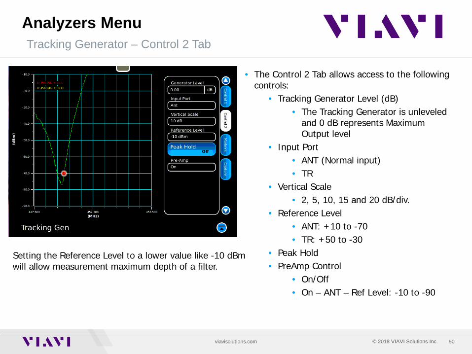
• The Control 2 Tab allows access to the following controls:
• Tracking Generator Level (dB) • The Tracking Generator is unleveled
and 0 dB represents Maximum Output level
• Input Port • ANT (Normal input) • TR
• Vertical Scale • 2, 5, 10, 15 and 20 dB/div.
• Reference Level • ANT: +10 to -70 • TR: +50 to -30
• Peak Hold • PreAmp Control
• On/Off • On – ANT – Ref Level: -10 to -90
Setting the Reference Level to a lower value like -10 dBm will allow measurement maximum depth of a filter.
51 © 2018 VIAVI Solutions Inc. viavisolutions.com
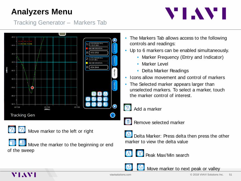
Analyzers Menu Tracking Generator – Markers Tab
• The Markers Tab allows access to the following controls and readings:
• Up to 6 markers can be enabled simultaneously. • Marker Frequency (Entry and Indicator) • Marker Level • Delta Marker Readings
• Icons allow movement and control of markers • The Selected marker appears larger than
unselected markers. To select a marker, touch the marker control of interest.
Add a marker Remove selected marker Delta Marker: Press delta then press the other marker to view the delta value Peak Max/Min search Move marker to next peak or valley
Move marker to the left or right Move the marker to the beginning or end of the sweep
52 © 2018 VIAVI Solutions Inc. viavisolutions.com
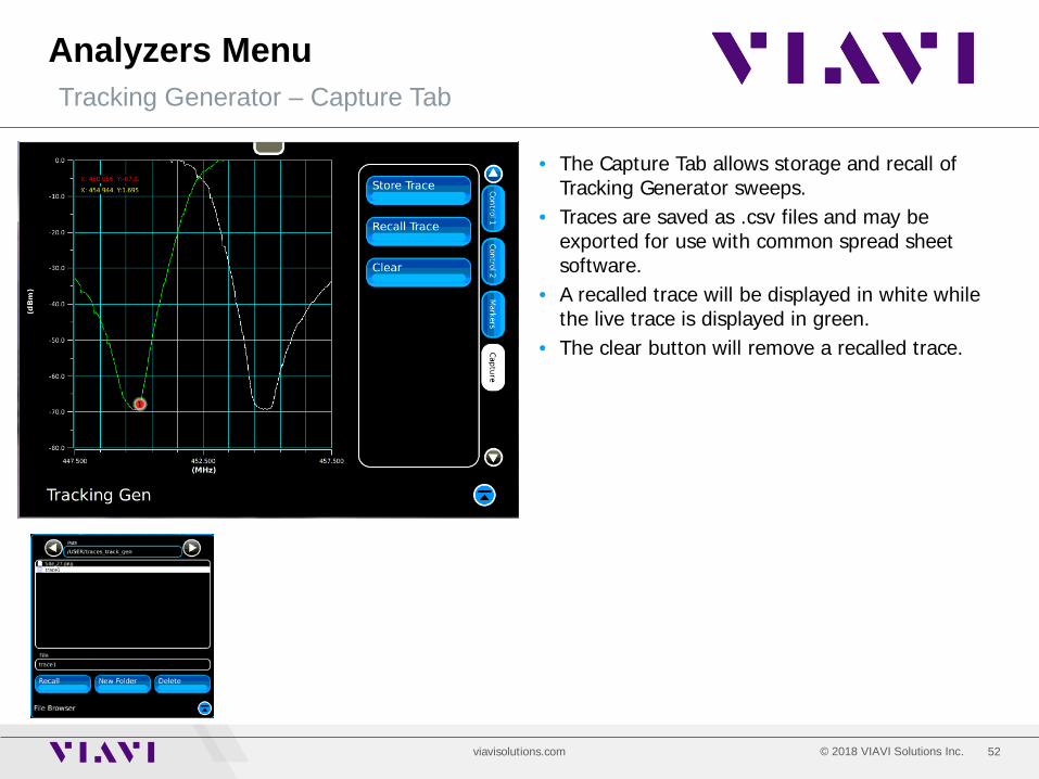
Analyzers Menu Tracking Generator – Capture Tab
• The Capture Tab allows storage and recall of Tracking Generator sweeps.
• Traces are saved as .csv files and may be exported for use with common spread sheet software.
• A recalled trace will be displayed in white while the live trace is displayed in green.
• The clear button will remove a recalled trace.

53 © 2018 VIAVI Solutions Inc. viavisolutions.com
Analyzers Menu Digital Plots – Optional Included with P25, DMR, NXDN, dPMR, ARIB T98
• Digital Plots Tile offers 3 different graphical views of a digital signal • Distribution Plot: Shows how often each symbol is accessed. • Constellation Plot: Shows Symbol Deviation symmetry. • Eye Diagram: Symbol clock error will cause the signal to be unstable around the center vertical
line. • The Cycle button will rotate through the three different views. • The Distribution and Constellation displays can clearly show issues with symbol deviation. • The Eye diagram can show issues with Symbol Clock Error.
54 © 2018 VIAVI Solutions Inc. viavisolutions.com
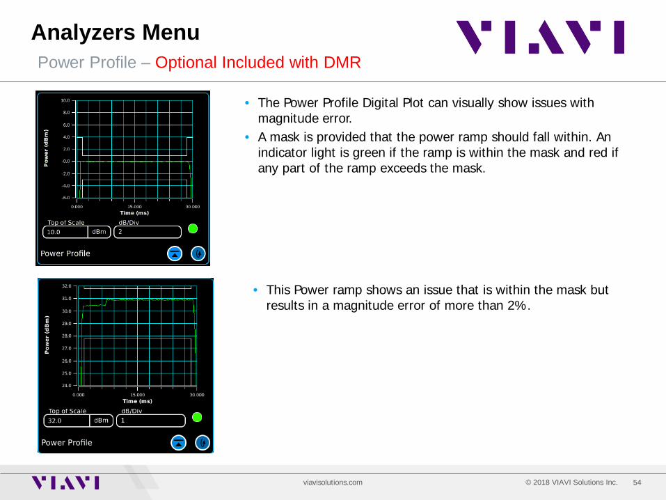
Analyzers Menu Power Profile – Optional Included with DMR
• The Power Profile Digital Plot can visually show issues with magnitude error.
• A mask is provided that the power ramp should fall within. An indicator light is green if the ramp is within the mask and red if any part of the ramp exceeds the mask.
• This Power ramp shows an issue that is within the mask but results in a magnitude error of more than 2%.
55 © 2018 VIAVI Solutions Inc. viavisolutions.com
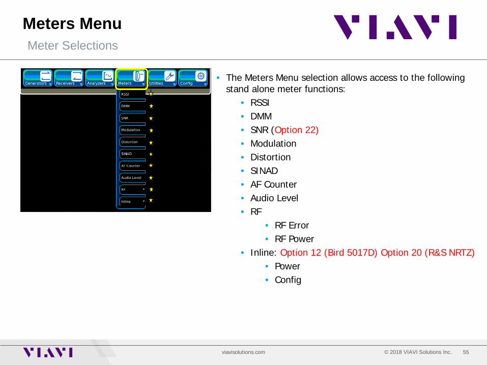
Meters Menu Meter Selections
• The Meters Menu selection allows access to the following stand alone meter functions:
• RSSI • DMM • SNR (Option 22) • Modulation • Distortion • SINAD • AF Counter • Audio Level • RF
• RF Error • RF Power
• Inline: Option 12 (Bird 5017D) Option 20 (R&S NRTZ) • Power • Config
56 © 2018 VIAVI Solutions Inc. viavisolutions.com
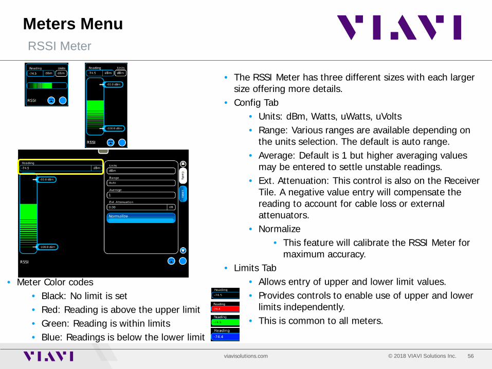
Meters Menu RSSI Meter
• The RSSI Meter has three different sizes with each larger size offering more details.
• Config Tab • Units: dBm, Watts, uWatts, uVolts • Range: Various ranges are available depending on
the units selection. The default is auto range. • Average: Default is 1 but higher averaging values
may be entered to settle unstable readings. • Ext. Attenuation: This control is also on the Receiver
Tile. A negative value entry will compensate the reading to account for cable loss or external attenuators.
• Normalize • This feature will calibrate the RSSI Meter for
maximum accuracy. • Limits Tab
• Allows entry of upper and lower limit values. • Provides controls to enable use of upper and lower
limits independently. • This is common to all meters.
• Meter Color codes • Black: No limit is set • Red: Reading is above the upper limit • Green: Reading is within limits • Blue: Readings is below the lower limit
57 © 2018 VIAVI Solutions Inc. viavisolutions.com
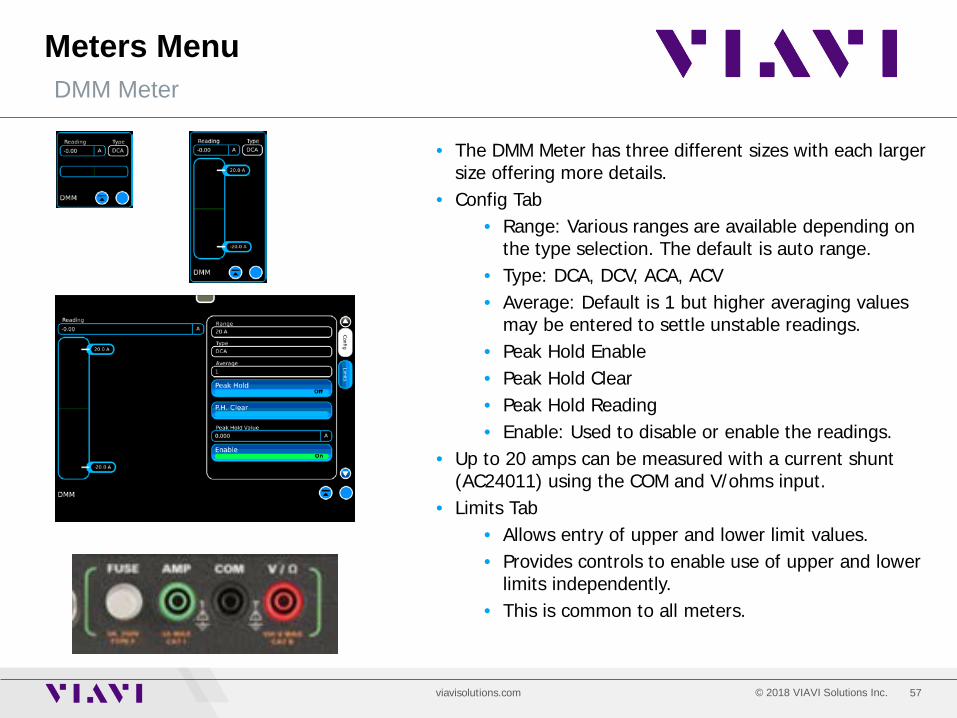
Meters Menu DMM Meter
• The DMM Meter has three different sizes with each larger size offering more details.
• Config Tab • Range: Various ranges are available depending on
the type selection. The default is auto range. • Type: DCA, DCV, ACA, ACV • Average: Default is 1 but higher averaging values
may be entered to settle unstable readings. • Peak Hold Enable • Peak Hold Clear • Peak Hold Reading • Enable: Used to disable or enable the readings.
• Up to 20 amps can be measured with a current shunt (AC24011) using the COM and V/ohms input.
• Limits Tab • Allows entry of upper and lower limit values. • Provides controls to enable use of upper and lower
limits independently. • This is common to all meters.

58 © 2018 VIAVI Solutions Inc. viavisolutions.com
Meters Menu SNR Meter – Option 022
• The SNR Meter • Type
• Demod SNR: Used for transmitter testing • Measured signal is the 8800SX Receiver
Demod signal. • Transmitter is externally modulated with
AF Generator 1. • Audio SNR: Used for receiver testing
• Measured signal is Audio IN • The 8800SX Modulator is used to
modulate the generator that injected into the radio receiver.
• Range • Auto or fixed ranges
• Enable: Start or stop the SNR Meter operation. • Limits Tab
• Allows entry of upper and lower limit values. • Provides controls to enable use of upper and lower
limits independently. • This is common to all meters.
59 © 2018 VIAVI Solutions Inc. viavisolutions.com
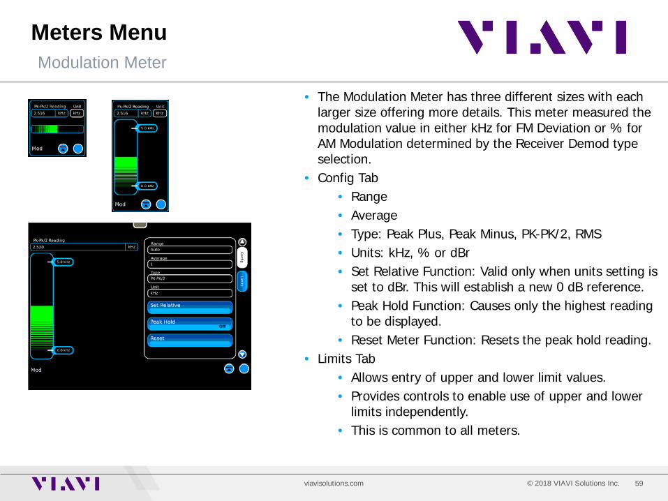
Meters Menu Modulation Meter
• The Modulation Meter has three different sizes with each larger size offering more details. This meter measured the modulation value in either kHz for FM Deviation or % for AM Modulation determined by the Receiver Demod type selection.
• Config Tab • Range • Average • Type: Peak Plus, Peak Minus, PK-PK/2, RMS • Units: kHz, % or dBr • Set Relative Function: Valid only when units setting is
set to dBr. This will establish a new 0 dB reference. • Peak Hold Function: Causes only the highest reading
to be displayed. • Reset Meter Function: Resets the peak hold reading.
• Limits Tab • Allows entry of upper and lower limit values. • Provides controls to enable use of upper and lower
limits independently. • This is common to all meters.

60 © 2018 VIAVI Solutions Inc. viavisolutions.com
Meters Menu Distortion Meter
• The Distortion Meter has three different sizes with each larger size offering more details.
• Config Tab • Source: Audio In or Receiver Demod • Range: Auto or fixed • Average: Sets the number of readings to average.
• For unstable signals, increase averaging. • Notch Frequency: Option 021
• The Standard Notch Frequency is 1 kHz. • Option 021 allows the notch frequency to be
varied between 1000 Hz and 5000 Hz.
• Limits Tab • Allows entry of upper and lower limit values. • Provides controls to enable use of upper and lower
limits independently. • This is common to all meters.
61 © 2018 VIAVI Solutions Inc. viavisolutions.com
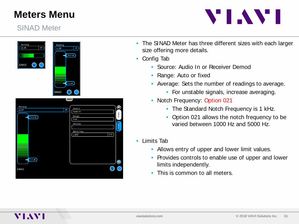
Meters Menu SINAD Meter
• The SINAD Meter has three different sizes with each larger size offering more details.
• Config Tab • Source: Audio In or Receiver Demod • Range: Auto or fixed • Average: Sets the number of readings to average.
• For unstable signals, increase averaging. • Notch Frequency: Option 021
• The Standard Notch Frequency is 1 kHz. • Option 021 allows the notch frequency to be
varied between 1000 Hz and 5000 Hz.
• Limits Tab • Allows entry of upper and lower limit values. • Provides controls to enable use of upper and lower
limits independently. • This is common to all meters.
62 © 2018 VIAVI Solutions Inc. viavisolutions.com
Meters Menu AF Counter
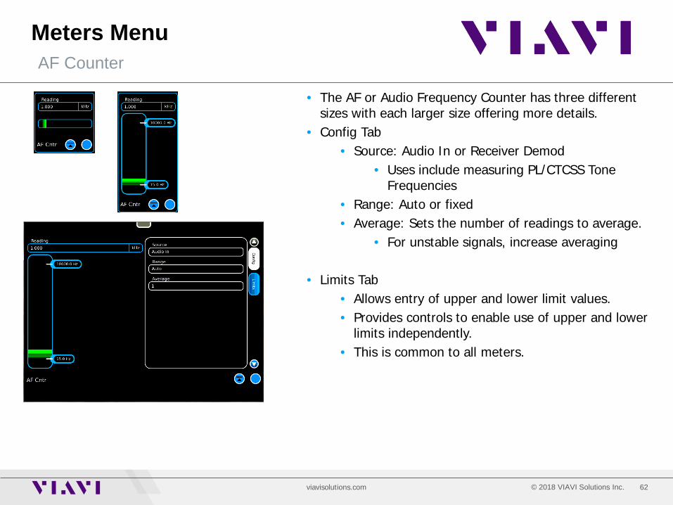
• The AF or Audio Frequency Counter has three different sizes with each larger size offering more details.
• Config Tab • Source: Audio In or Receiver Demod
• Uses include measuring PL/CTCSS Tone Frequencies
• Range: Auto or fixed • Average: Sets the number of readings to average.
• For unstable signals, increase averaging
• Limits Tab • Allows entry of upper and lower limit values. • Provides controls to enable use of upper and lower
limits independently. • This is common to all meters.
63 © 2018 VIAVI Solutions Inc. viavisolutions.com
Meters Menu Audio Level Meter
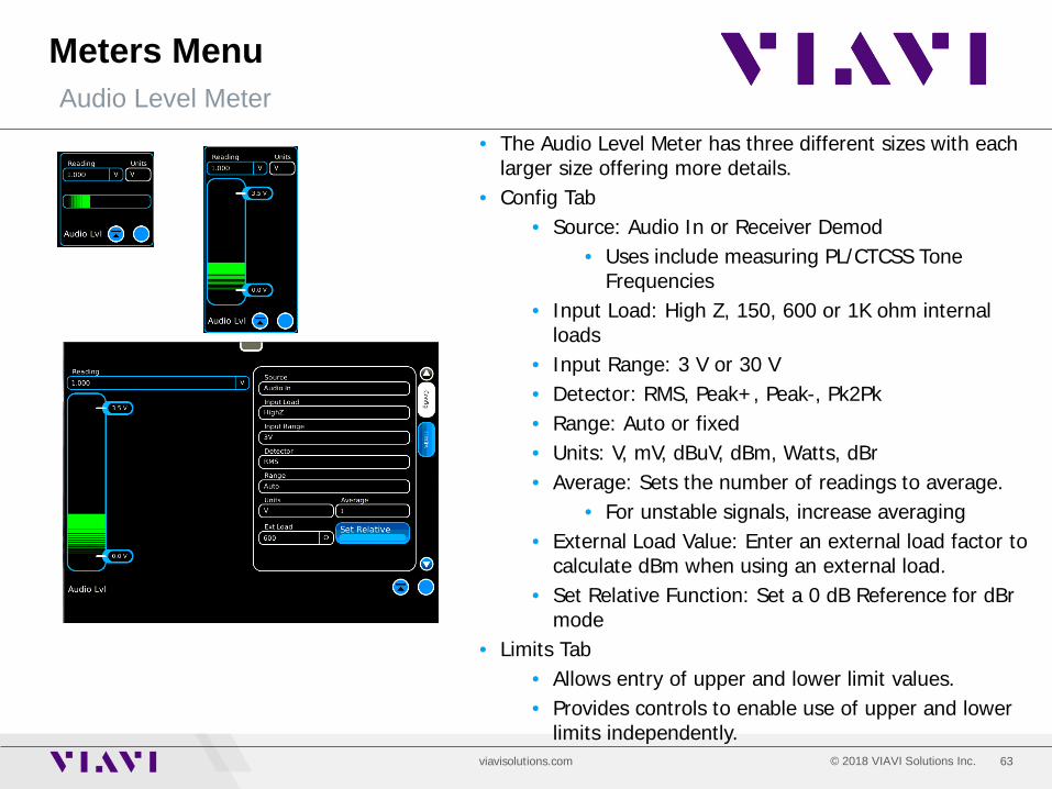
• The Audio Level Meter has three different sizes with each larger size offering more details.
• Config Tab • Source: Audio In or Receiver Demod
• Uses include measuring PL/CTCSS Tone Frequencies
• Input Load: High Z, 150, 600 or 1K ohm internal loads
• Input Range: 3 V or 30 V • Detector: RMS, Peak+, Peak-, Pk2Pk • Range: Auto or fixed • Units: V, mV, dBuV, dBm, Watts, dBr • Average: Sets the number of readings to average.
• For unstable signals, increase averaging • External Load Value: Enter an external load factor to
calculate dBm when using an external load. • Set Relative Function: Set a 0 dB Reference for dBr
mode • Limits Tab
• Allows entry of upper and lower limit values. • Provides controls to enable use of upper and lower
limits independently.
64 © 2018 VIAVI Solutions Inc. viavisolutions.com
Meters Menu RF Error Meter
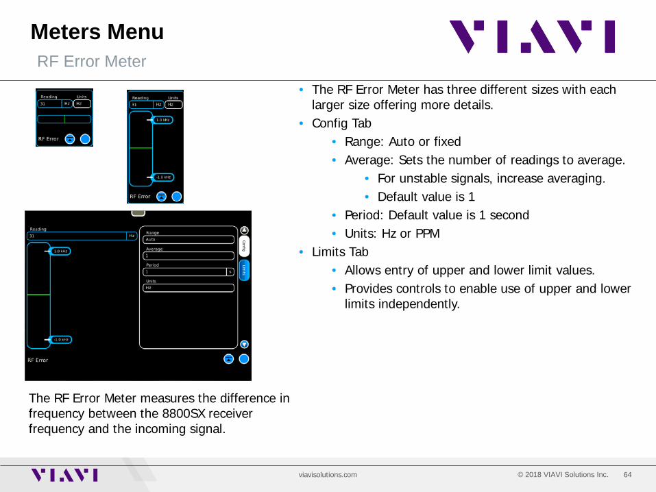
• The RF Error Meter has three different sizes with each larger size offering more details.
• Config Tab • Range: Auto or fixed • Average: Sets the number of readings to average.
• For unstable signals, increase averaging. • Default value is 1
• Period: Default value is 1 second • Units: Hz or PPM
• Limits Tab • Allows entry of upper and lower limit values. • Provides controls to enable use of upper and lower
limits independently.
The RF Error Meter measures the difference in frequency between the 8800SX receiver frequency and the incoming signal.
65 © 2018 VIAVI Solutions Inc. viavisolutions.com
Meters Menu RF Power Meter
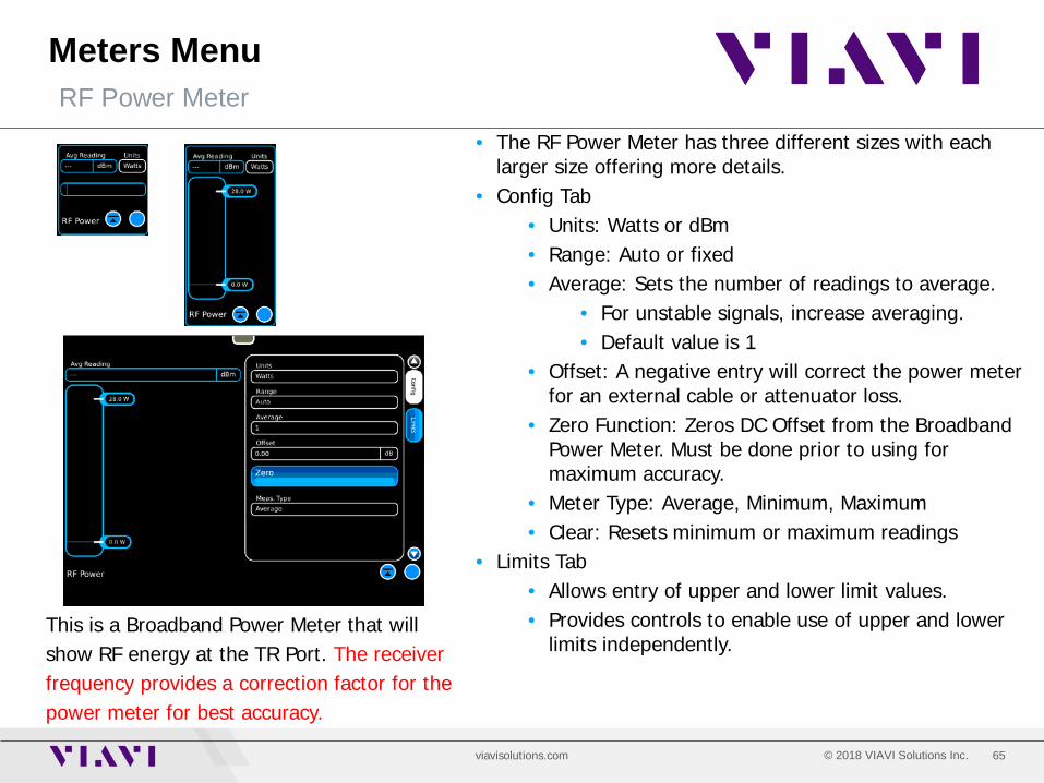
• The RF Power Meter has three different sizes with each larger size offering more details.
• Config Tab • Units: Watts or dBm • Range: Auto or fixed • Average: Sets the number of readings to average.
• For unstable signals, increase averaging. • Default value is 1
• Offset: A negative entry will correct the power meter for an external cable or attenuator loss.
• Zero Function: Zeros DC Offset from the Broadband Power Meter. Must be done prior to using for maximum accuracy.
• Meter Type: Average, Minimum, Maximum • Clear: Resets minimum or maximum readings
• Limits Tab • Allows entry of upper and lower limit values. • Provides controls to enable use of upper and lower
limits independently. This is a Broadband Power Meter that will show RF energy at the TR Port. The receiver frequency provides a correction factor for the power meter for best accuracy.
66 © 2018 VIAVI Solutions Inc. viavisolutions.com
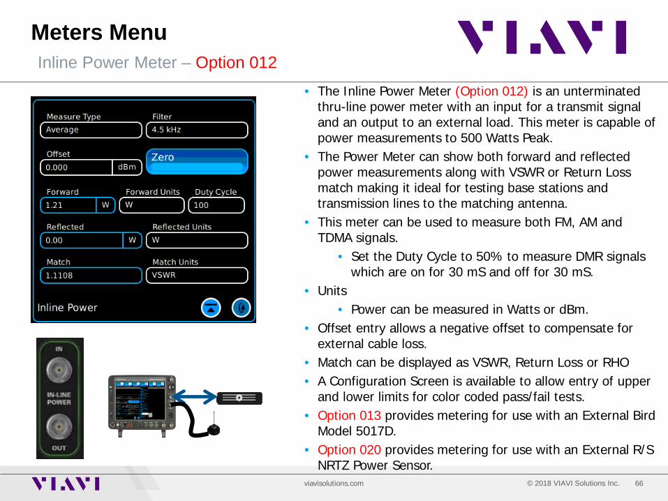
Meters Menu Inline Power Meter – Option 012
• The Inline Power Meter (Option 012) is an unterminated thru-line power meter with an input for a transmit signal and an output to an external load. This meter is capable of power measurements to 500 Watts Peak.
• The Power Meter can show both forward and reflected power measurements along with VSWR or Return Loss match making it ideal for testing base stations and transmission lines to the matching antenna.
• This meter can be used to measure both FM, AM and TDMA signals.
• Set the Duty Cycle to 50% to measure DMR signals which are on for 30 mS and off for 30 mS.
• Units • Power can be measured in Watts or dBm.
• Offset entry allows a negative offset to compensate for external cable loss.
• Match can be displayed as VSWR, Return Loss or RHO • A Configuration Screen is available to allow entry of upper
and lower limits for color coded pass/fail tests. • Option 013 provides metering for use with an External Bird
Model 5017D. • Option 020 provides metering for use with an External R/S
NRTZ Power Sensor.

67 © 2018 VIAVI Solutions Inc. viavisolutions.com
Utilities Menu Utilities Selections
• The Utilities Menu selection allows access to the following stand alone meter functions:
• Selection of optional languages • Presets
• Three standard presets • Seven user definable presets
• Store/Recall setups with pre-configured samples • Cal • Software
• Option installation • System information/network settings • Software update
• Freq Flex – Timebase optimizaton • Aeroflex • Self-Test • Auto-Test – Optional Automated OEM Radio Alignment • File Manager
• Transfer files to and from the 8800SX

68 © 2018 VIAVI Solutions Inc. viavisolutions.com
Utilities Menu
• The small tab at the top center of the display allows access to the launch bar.
• Simply touch the tab and the launch bar will expand.
Presets
• Press the Utilities Tab and then the Presets Menu to rapidly configure the 8800SX for either analog or digital testing.
Presets quickly configure standard tile selections and locations.
69 © 2018 VIAVI Solutions Inc. viavisolutions.com
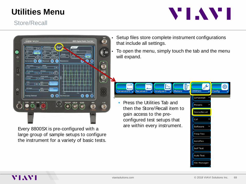
Utilities Menu
• Setup files store complete instrument configurations that include all settings.
• To open the menu, simply touch the tab and the menu will expand.
Store/Recall
• Press the Utilities Tab and then the Store/Recall item to gain access to the pre-configured test setups that are within every instrument.
Every 8800SX is pre-configured with a large group of sample setups to configure the instrument for a variety of basic tests.

70 © 2018 VIAVI Solutions Inc. viavisolutions.com
Utilities Menu
• When first entering the Store/Recall Menu, a folder named “Sample Setups” will be visible.
• To enter the folder, touch or highlight the Sample Setups item on the list then press the icon to enter the folder.
Store/Recall Navigation
71 © 2018 VIAVI Solutions Inc. viavisolutions.com
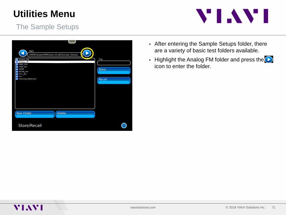
Utilities Menu
• After entering the Sample Setups folder, there are a variety of basic test folders available.
• Highlight the Analog FM folder and press the icon to enter the folder.
The Sample Setups
72 © 2018 VIAVI Solutions Inc. viavisolutions.com
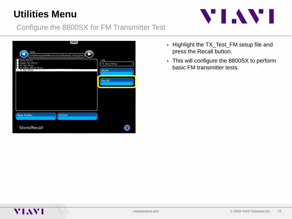
Utilities Menu
• Highlight the TX_Test_FM setup file and press the Recall button.
• This will configure the 8800SX to perform basic FM transmitter tests.
Configure the 8800SX for FM Transmitter Test
73 © 2018 VIAVI Solutions Inc. viavisolutions.com
Utilities Software - Options
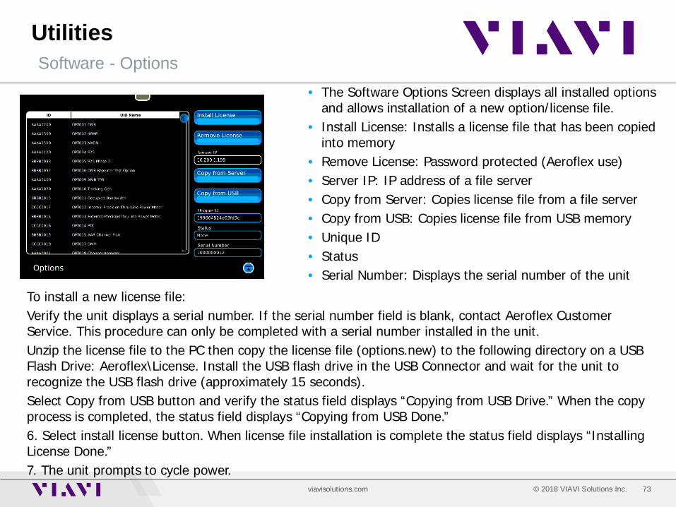
• The Software Options Screen displays all installed options and allows installation of a new option/license file.
• Install License: Installs a license file that has been copied into memory
• Remove License: Password protected (Aeroflex use) • Server IP: IP address of a file server • Copy from Server: Copies license file from a file server • Copy from USB: Copies license file from USB memory • Unique ID • Status • Serial Number: Displays the serial number of the unit
To install a new license file: Verify the unit displays a serial number. If the serial number field is blank, contact Aeroflex Customer Service. This procedure can only be completed with a serial number installed in the unit. Unzip the license file to the PC then copy the license file (options.new) to the following directory on a USB Flash Drive: Aeroflex\License. Install the USB flash drive in the USB Connector and wait for the unit to recognize the USB flash drive (approximately 15 seconds). Select Copy from USB button and verify the status field displays “Copying from USB Drive.” When the copy process is completed, the status field displays “Copying from USB Done.” 6. Select install license button. When license file installation is complete the status field displays “Installing License Done.” 7. The unit prompts to cycle power.
74 © 2018 VIAVI Solutions Inc. viavisolutions.com
Utilities Software – System – Status and Hardware Tabs
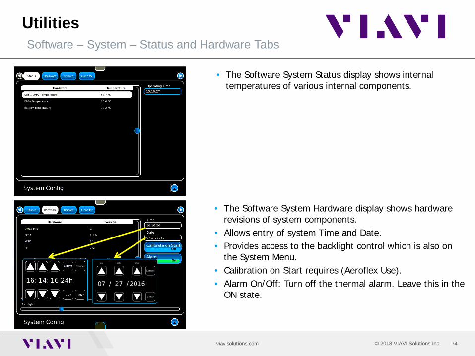
• The Software System Status display shows internal temperatures of various internal components.
• The Software System Hardware display shows hardware revisions of system components.
• Allows entry of system Time and Date. • Provides access to the backlight control which is also on
the System Menu. • Calibration on Start requires (Aeroflex Use). • Alarm On/Off: Turn off the thermal alarm. Leave this in the
ON state.

75 © 2018 VIAVI Solutions Inc. viavisolutions.com
Utilities Software – System – Remote and Clone Me Tabs
• The Software System Remote Tab allows entry of Static or DHCP mode.
• DHCP: Network assigns an IP address and other parameters.
• Static: Manually enter IP Address, Subnet Mask, and Gateway values.
• With networking enabled, it is possible to use a VNC viewer application on a computer to remotely control the 8800SX. Files may also be transferred with a WINSCP application.
• NOTE: If networking is not required, set the mode to OFF. This will reduce the bootup time of the 8800SX.
• The Software System Clone Me Tab allows the ability to copy setups files from one 8800SX to another over an Ethernet interface. Enter the source and target IP addresses select Setups Copy.
76 © 2018 VIAVI Solutions Inc. viavisolutions.com
Utilities Software – Freq-Flex
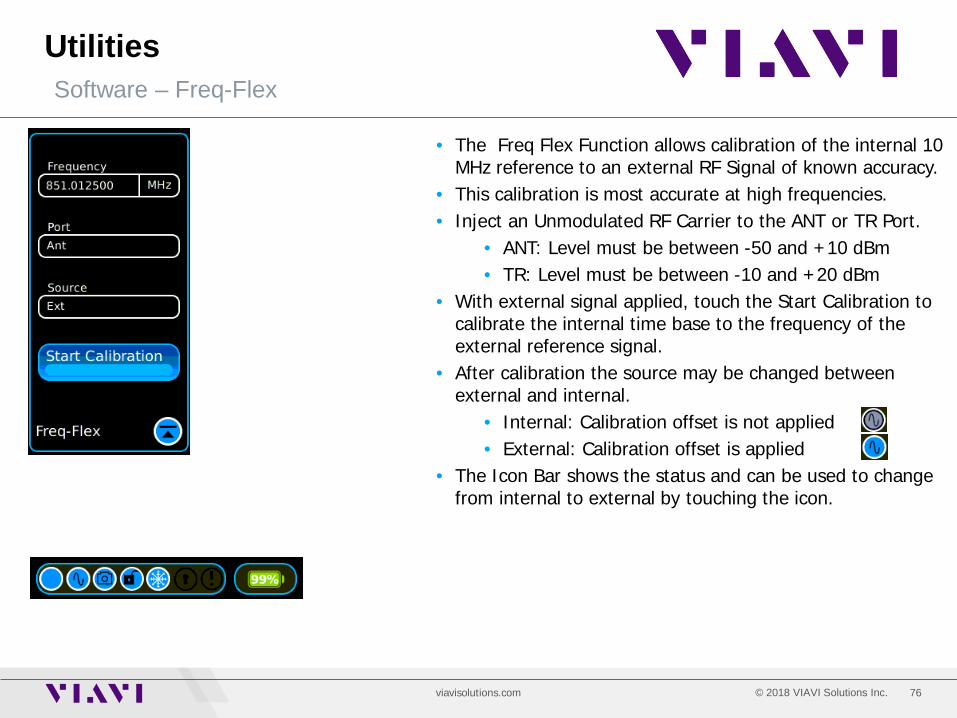
• The Freq Flex Function allows calibration of the internal 10 MHz reference to an external RF Signal of known accuracy.
• This calibration is most accurate at high frequencies. • Inject an Unmodulated RF Carrier to the ANT or TR Port.
• ANT: Level must be between -50 and +10 dBm • TR: Level must be between -10 and +20 dBm
• With external signal applied, touch the Start Calibration to calibrate the internal time base to the frequency of the external reference signal.
• After calibration the source may be changed between external and internal.
• Internal: Calibration offset is not applied • External: Calibration offset is applied
• The Icon Bar shows the status and can be used to change from internal to external by touching the icon.

77 © 2018 VIAVI Solutions Inc. viavisolutions.com
Utilities Auto-Test System - Optional
• The 8800SX supports a growing list of automated test and alignment applications and are based on OEM alignment and test specifications for each specific model.
• Connect the radio’s USB Programming Cable from the radio to one of the 8800SX USB Ports.
• Connect an RF Cable from the radio’s TX Output to the 8800SX TR Port.
• Turn on the radio and select Read Radio and the 8800SX will identify the model of radio that is connected.
• Either Test Only or Align and Test can be selected. • Touch the Run button to execute the process.
• Test results are automatically stored internally and a filename is created based on the Model, Serial Number and Time/Date stamp.
• All radio information is captured including radio software versions and options.

78 © 2018 VIAVI Solutions Inc. viavisolutions.com
Utilities File Manager
• The File Manager allows the ability to transfer files from the 8800SX storage directories to a USB memory stick.
• The 8800SX storage directories include: • Auto-Test Results • Cable Types: Used for DTF measurements • Frequency Lists: Stored Frequency lists • Presets • Save Recall: Stored setup files • Snapshot: Stored screen shots • Traces_analyzer: Stored spectrum analyzer traces • Traces_oscope: Stored scope traces • Traces_track_gen: Stored traces from the Tracking
Generator system. Includes DTF and Return Loss Traces.
• Touch a directory name to highlight it then use the arrow keys next to the path name to navigate to the directory and file group of interest.
• Touch the usbstick_sda1 folder and use the path arrows above to navigate to the USB folder of interest.
• Files can now be transferred from either direction.
79 © 2018 VIAVI Solutions Inc. viavisolutions.com
Configuration Menu Configuration Selections
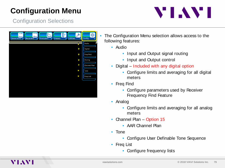
• The Configuration Menu selection allows access to the following features:
• Audio • Input and Output signal routing • Input and Output control
• Digital – Included with any digital option • Configure limits and averaging for all digital
meters • Freq Find
• Configure parameters used by Receiver Frequency Find Feature
• Analog • Configure limits and averaging for all analog
meters • Channel Plan – Option 15
• AAR Channel Plan • Tone
• Configure User Definable Tone Sequence • Freq List
• Configure frequency lists

80 © 2018 VIAVI Solutions Inc. viavisolutions.com
Config Audio
• The Audio Configuration Tile is used to configure Audio Routing, Input Range and Filtering.
• Audio Tab • Audio IN Load: High Z, 150 Ohm, 600 Ohm or 1 k
Ohm internal load selections. • Audio IN Range: 3 V or 30 V
• Set this range to be appropriate for audio signals coming into the Audio IN Port.
• Audio OUT Port • AF GEN: Audio Generator is routed to the AUD
OUT Port. • DEMOD: Receiver Demod Audio is routed to
the AUD OUT Port. • Audio IN Filter: Choose from a list of low pass, high
pass and band pass filters to filter audio coming into the AUD IN Port.
• Routing Tab • Define audio signal that various devices may be
evaluating. Choose between Audio IN, Receiver Demod and others. Selections are different for different devices.
Audio in Demod AF Gen
Scope Audio in
Scope Demod Audio in
Audio in Demod
Audio in Demod
Audio in Demod
81 © 2018 VIAVI Solutions Inc. viavisolutions.com
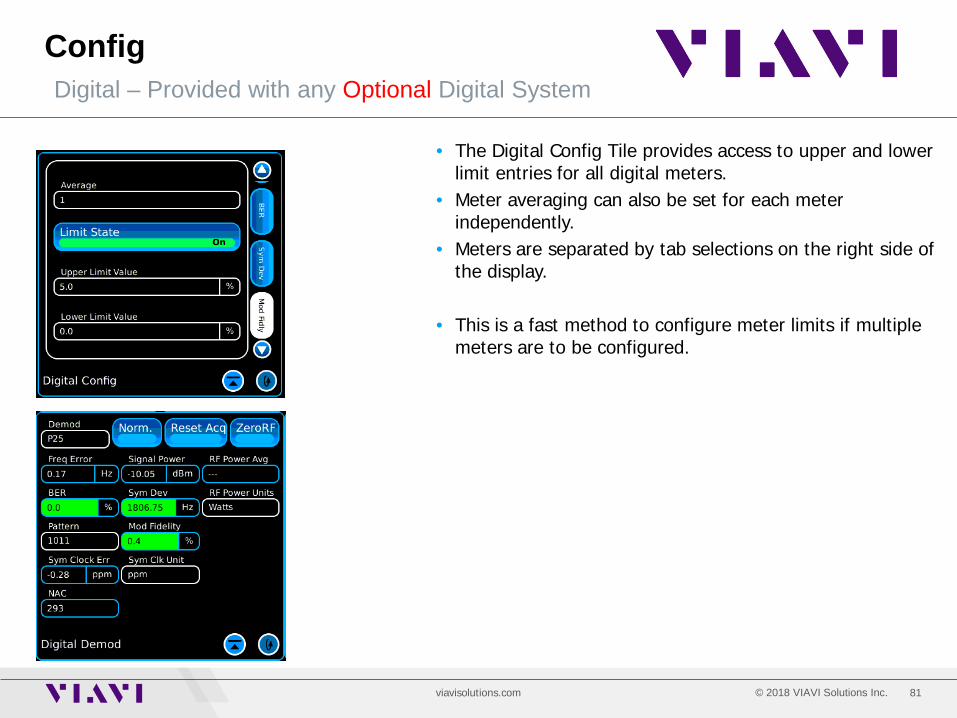
Config Digital – Provided with any Optional Digital System
• The Digital Config Tile provides access to upper and lower limit entries for all digital meters.
• Meter averaging can also be set for each meter independently.
• Meters are separated by tab selections on the right side of the display.
• This is a fast method to configure meter limits if multiple meters are to be configured.

82 © 2018 VIAVI Solutions Inc. viavisolutions.com
Config Frequency Find
• The Frequency Find Configuration Tile allows configuration of the frequency search parameters.
• Start Frequency: Begin the search at start frequency • Stop Frequency: Search up to the stop frequency • Channel Spacing: Step size of the search • Threshold: Signal must be greater than this value
• To initiate a search for a transmitter, use the Freq Find
Button on the Receiver Tile.

83 © 2018 VIAVI Solutions Inc. viavisolutions.com
Config Analog Config
• The Analog Config Tile provides access to upper and lower limit entries for all analog meters.
• Meters are separated by tab selections on the right side of the display.
• This is a much faster method to configure meter limits if multiple meters are to be configured.
84 © 2018 VIAVI Solutions Inc. viavisolutions.com
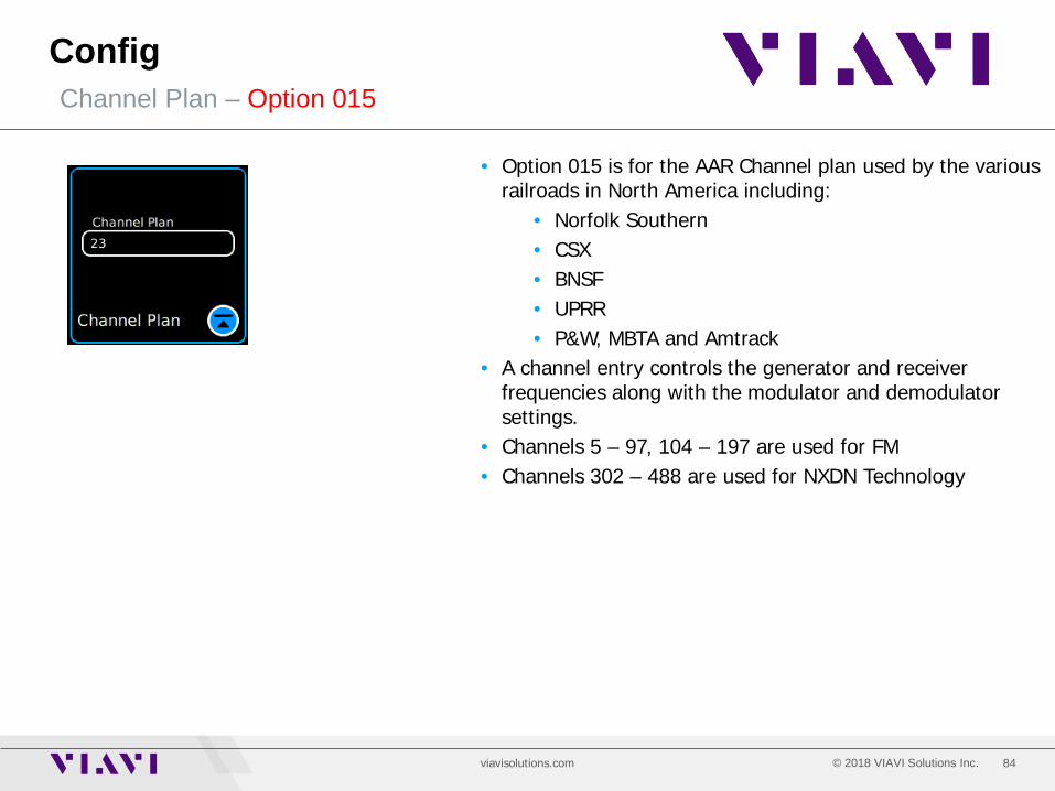
Config Channel Plan – Option 015
• Option 015 is for the AAR Channel plan used by the various railroads in North America including:
• Norfolk Southern • CSX • BNSF • UPRR • P&W, MBTA and Amtrack
• A channel entry controls the generator and receiver frequencies along with the modulator and demodulator settings.
• Channels 5 – 97, 104 – 197 are used for FM • Channels 302 – 488 are used for NXDN Technology
85 © 2018 VIAVI Solutions Inc. viavisolutions.com
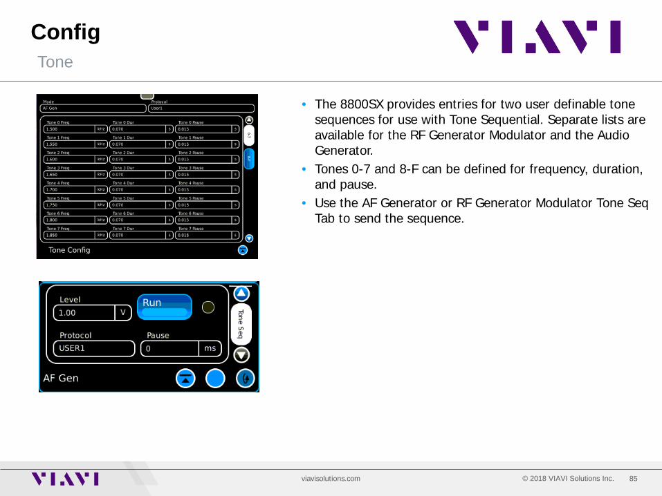
Config Tone
• The 8800SX provides entries for two user definable tone sequences for use with Tone Sequential. Separate lists are available for the RF Generator Modulator and the Audio Generator.
• Tones 0-7 and 8-F can be defined for frequency, duration, and pause.
• Use the AF Generator or RF Generator Modulator Tone Seq Tab to send the sequence.
86 © 2018 VIAVI Solutions Inc. viavisolutions.com
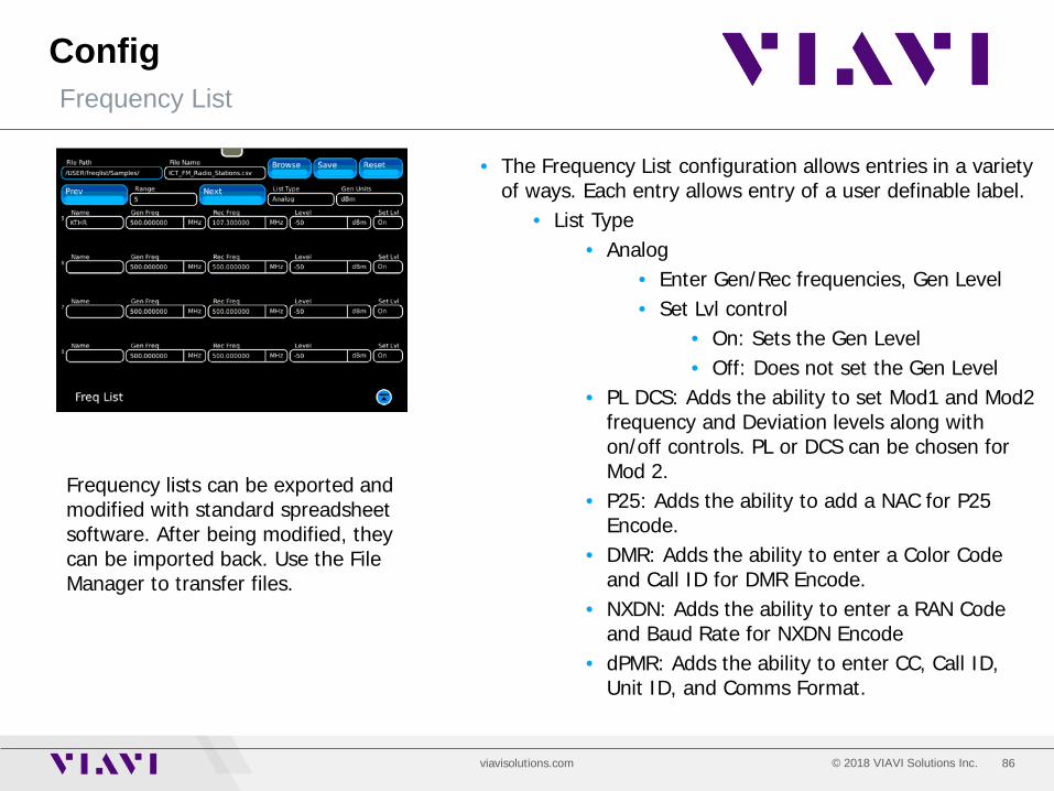
Config Frequency List
• The Frequency List configuration allows entries in a variety of ways. Each entry allows entry of a user definable label.
• List Type • Analog
• Enter Gen/Rec frequencies, Gen Level • Set Lvl control
• On: Sets the Gen Level • Off: Does not set the Gen Level
• PL DCS: Adds the ability to set Mod1 and Mod2 frequency and Deviation levels along with on/off controls. PL or DCS can be chosen for Mod 2.
• P25: Adds the ability to add a NAC for P25 Encode.
• DMR: Adds the ability to enter a Color Code and Call ID for DMR Encode.
• NXDN: Adds the ability to enter a RAN Code and Baud Rate for NXDN Encode
• dPMR: Adds the ability to enter CC, Call ID, Unit ID, and Comms Format.
Frequency lists can be exported and modified with standard spreadsheet software. After being modified, they can be imported back. Use the File Manager to transfer files.
87 © 2018 VIAVI Solutions Inc. viavisolutions.com
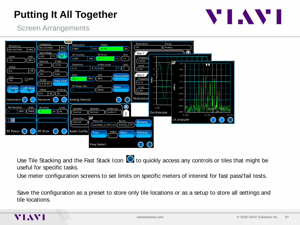
Putting It All Together Screen Arrangements
Use Tile Stacking and the Fast Stack Icon to quickly access any controls or tiles that might be useful for specific tasks. Use meter configuration screens to set limits on specific meters of interest for fast pass/fail tests. Save the configuration as a preset to store only tile locations or as a setup to store all settings and tile locations.
88 © 2018 VIAVI Solutions Inc. viavisolutions.com
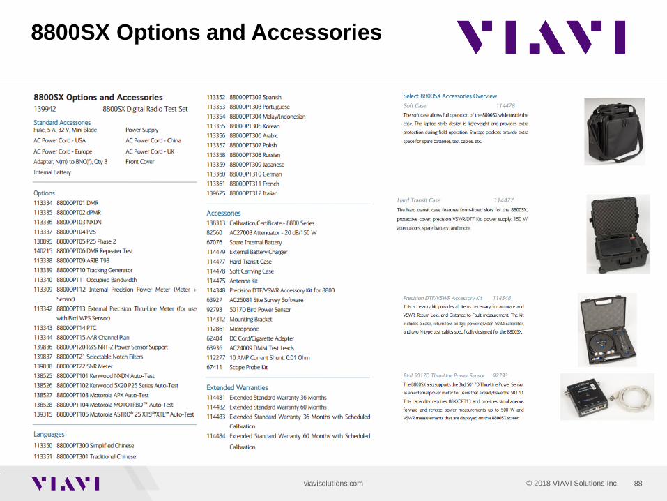
8800SX Options and Accessories
89 © 2018 VIAVI Solutions Inc. viavisolutions.com
Questions or Comments?
For information about pricing for our products, contact the sales office by calling VIAVI Solutions at (800) 835-2352 or emailing [email protected]. For technical/product support, calibration, maintenance and general customer service inquiries, you can contact our help desk by clicking here, calling (800) 835-2350, or emailing [email protected]. Click here for more information on the 3920B and latest software versions and training materials.
Contact Information