introduction to telecom networks
DESCRIPTION
Telecom Network Interfaces and description of various interfaces like IUB, MUB,Gx/Gy,Gi and many more with description of each in detail and Network architecture of telecom nodes and domainTRANSCRIPT

NETWORK ARCHITECTURE OF GSM(GPRS/EDGE), WCDMA, LTE, ERICSSON CHARGING SYSTEM
INTRODUCTION TO TELECOM NETWORKS
© Ericsson AB 2014 | 2014-09-10 | Page 2
SS7 Fundamentals
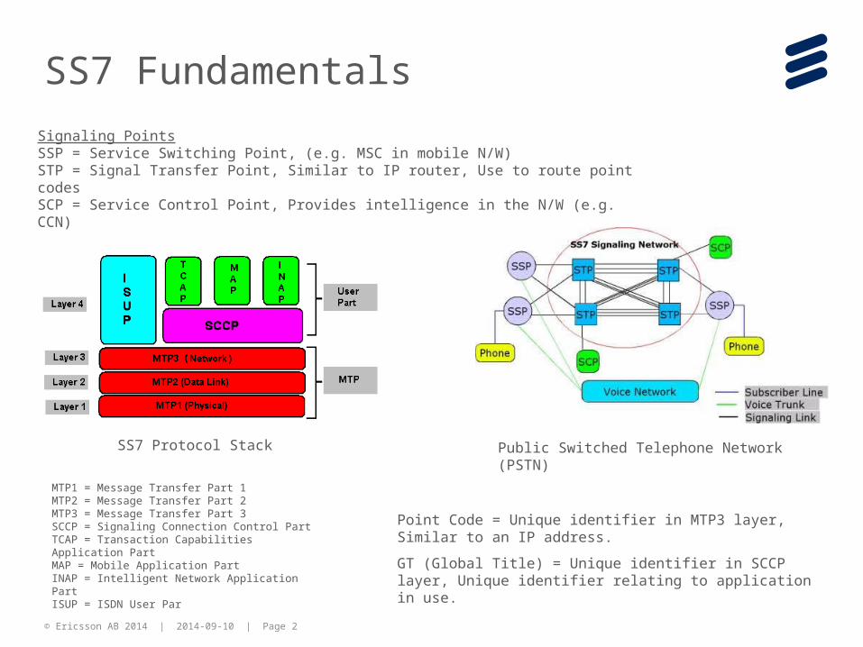
Signaling PointsSSP = Service Switching Point, (e.g. MSC in mobile N/W)STP = Signal Transfer Point, Similar to IP router, Use to route point codesSCP = Service Control Point, Provides intelligence in the N/W (e.g. CCN)
Point Code = Unique identifier in MTP3 layer, Similar to an IP address.
GT (Global Title) = Unique identifier in SCCP layer, Unique identifier relating to application in use.
SS7 Protocol Stack Public Switched Telephone Network (PSTN)
MTP1 = Message Transfer Part 1MTP2 = Message Transfer Part 2MTP3 = Message Transfer Part 3SCCP = Signaling Connection Control PartTCAP = Transaction Capabilities Application PartMAP = Mobile Application PartINAP = Intelligent Network Application PartISUP = ISDN User Par

© Ericsson AB 2014 | 2014-09-10 | Page 3
Sigtran (SS7 Over IP)
Application
SCTP
Internet
Network Access
ISUP, MAP, CAP, INAP
TCAP
SCCP
MTP3 M3UA
MTP2
MTP1
SS7 Protocol Stack
Sigtran Protocol Stack
The SIGTRAN protocol stack includes the Stream Control Transmission Protocol (SCTP) and user adaptations SUA (SCCP user adaptation layer), M3UA (MTP3 user adaptation layer)
The SIGTRAN stack functions can be divided into SCTP stacks and protocol stacks for Adaptation Layers. SCTP is responsible for reliable signaling transport, streaming, congestion avoidance and control, bundling and un-bundling, multi-homing and association management, security and user-transparent fault management. SCTP stack supports various user adaptations including M3UA, M2UA, IUA, M2PA and SUA.
© Ericsson AB 2014 | 2014-09-10 | Page 4
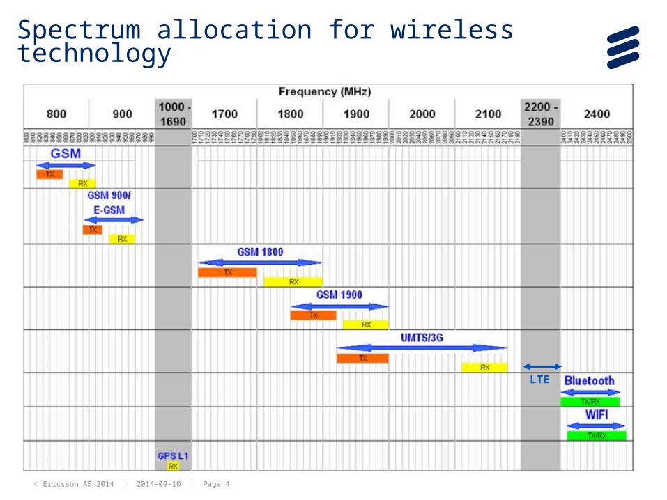
Spectrum allocation for wireless technology
LTE

© Ericsson AB 2014 | 2014-09-10 | Page 5
IP NW
IP NW
IP NW
2G
3G
LTE
802.11 a
802.11 b
802.11 g
802.11 n
ADSLModem DSLAM
BRAS
ISP
BTSBSC GGSN
ISP
ISP
Access Point Access Point
Controller
User
User
User
Broadband N/W Connectivity
Mobile N/W Connectivity
WiFi N/W Connectivity
BNG
Popular methods to access internet
Node-BENode-B
Core N/WAccess N/W
RNC PGW

© Ericsson AB 2014 | 2014-09-10 | Page 6
BSS — Base Station System
BTS — Base Transceiver Station
BSC — Base Station Controller
MS — Mobile Station
NSS — Network Sub-System
MSC — Mobile-service Switching Controller
VLR — Visitor Location Register
HLR — Home Location Register
AuC — Authentication Server
GMSC — Gateway MSC
GSM 2G Architecture
SS7BTS
BSCMSC
VLR
HLRAuC
GMSC
BSS
PSTN
NSS
AE
CD
PSTNAbis
B
H
MS
GSM — Global System for Mobile communication
EIR
F
UmTRC
Ater
G-SMS
SMS-IWMSC
SMS-GMSC
SC
C
E
SMS — GMSC Gateway MSC
SMS — IWMSC InterWorking MSC
SC — Service Center
SME — Short Messaging Entity
© Ericsson AB 2014 | 2014-09-10 | Page 7
2G-BLOCK of MS
Mobile station (MS)In GSM, the mobile station consists of four main components:
Mobile Termination (MT) - offers common functions of a such as: radio Transmission and handover, speech encoding and decoding, Error detection and correction, signalling and access to the SIM. The IMEI code is attached to the MT. It is equivalent to the network termination of an ISDN access.
Terminal Equipment (TE) - is any device connected to the MS offering services to the user. It does not contain any functions specific to GSM.
Terminal adapter (TA) - Provides access to the MT as if it was an ISDN network termination with extended capabilities.
Subscriber Identity Module (SIM) - is a removable subscriber identification token storing the IMSI a unique key shared with the mobile network operator and other data.
© Ericsson AB 2014 | 2014-09-10 | Page 8
2G Block BSSBASE STATION SYSTEMThe Base Station System (BSS) is composed of two major components. These are:Base Station Controller (BSC) and Base Transceiver Station (BTS)
BSCThe Base Station Controller (BSC) is the central point of the BSS.The BSC can manage the entire radio
network and performs the following functions:• Handling of the mobile station connection and handover• Radio network management• Transcoding and rate adaptation• Traffic concentration• Transmission management of the BTSs• Remote control of the BTSs
BTSThe Base Transceiver Station (BTS) includes all radio and transmission interface equipment needed in
one cell.
TRCThe transcoder is responsible for Transco ding the voice channel coding between the coding used in
the mobile network, and the coding used by the world's terrestrial circuit-switched network, the Public Switched Telephone Network.
© Ericsson AB 2014 | 2014-09-10 | Page 9
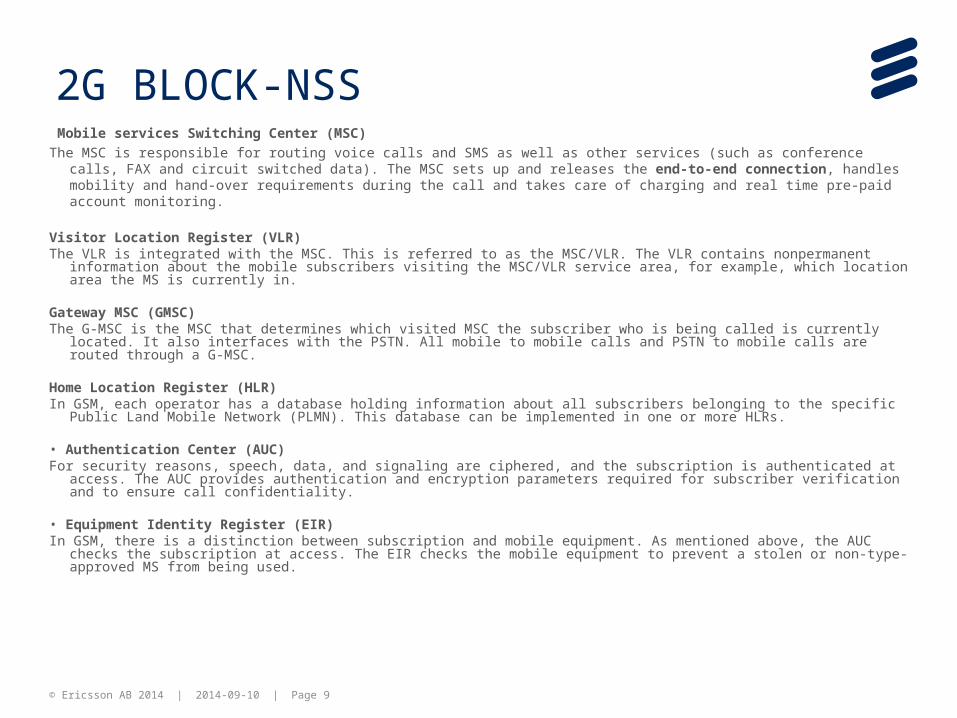
2G BLOCK-NSS Mobile services Switching Center (MSC)
The MSC is responsible for routing voice calls and SMS as well as other services (such as conference calls, FAX and circuit switched data). The MSC sets up and releases the end-to-end connection, handles mobility and hand-over requirements during the call and takes care of charging and real time pre-paid account monitoring.
Visitor Location Register (VLR)The VLR is integrated with the MSC. This is referred to as the MSC/VLR. The VLR contains nonpermanent information about
the mobile subscribers visiting the MSC/VLR service area, for example, which location area the MS is currently in.
Gateway MSC (GMSC)The G-MSC is the MSC that determines which visited MSC the subscriber who is being called is currently located. It also
interfaces with the PSTN. All mobile to mobile calls and PSTN to mobile calls are routed through a G-MSC.
Home Location Register (HLR)In GSM, each operator has a database holding information about all subscribers belonging to the specific Public Land Mobile
Network (PLMN). This database can be implemented in one or more HLRs.
• Authentication Center (AUC)For security reasons, speech, data, and signaling are ciphered, and the subscription is authenticated at access. The AUC
provides authentication and encryption parameters required for subscriber verification and to ensure call confidentiality.
• Equipment Identity Register (EIR)In GSM, there is a distinction between subscription and mobile equipment. As mentioned above, the AUC checks the
subscription at access. The EIR checks the mobile equipment to prevent a stolen or non-type-approved MS from being used.

© Ericsson AB 2014 | 2014-09-10 | Page 10
GSM INTERFACE
Interface
Between Description
UmMS-BSS The air interface is used for exchanges between a MS and a BSS.
Abis BSC-BTS This is a BSS internal interface that links the BSC and a BTS. The Abis interface allows control of radio equipment and radio frequency allocation in the BTS.
Ater BSC-TRC This interface is a proprietary interface used between the BSC and TRC for control of the Transcoder resources and the A-interface circuits.
A BSC/TRC-MSC The A interface is between the BSS and the MSC. It manages the allocation of suitable radio resources to the MSs and mobility management. It uses the BSSAP protocols (BSSMAP and DTAP).
B MSC-VLR The B interface handles signaling between the MSC and the VLR. Whenever the MSC needs to access data regarding an MS that is located in its area, it interrogates the VLR using the MAP/B protocol over the B interface.
C GMSC-HLR or SMSG-HLR The C interface is between the HLR and a GMSC or a SMSC. Each call that originates outside of GSM (such as an MS terminating call from the PSTN) must go through a gateway to obtain the routing information that is required to complete the call, and the MAP/C protocol over the C interface is used for this purpose. Also, the MSC can optionally forward billing information to the HLR after call clearing.
D HLR-VLR The D interface is between the HLR and VLR, and uses the MAP/D protocol to exchange data related to the location of the MS and subsets of subscriber data.
E MSC-MSC The E interface connects MSCs. The E interface exchanges data that is related to handover between the anchor and relay MSCs using the MAP/E protocol. The E interface can also be used to connect the GMSC to an SMSC.

© Ericsson AB 2014 | 2014-09-10 | Page 11
GSM INTERFACE
Interface
Between Description
F MSC-EIR The F interface connects the MSC to the EIR and uses the MAP/F protocol to verify the status of the IMEI that the MSC has retrieved from the MS.
G VLR-VLR The G interface interconnects two VLRs of different MSCs and uses the MAP/G protocol to transfer subscriber information—for example, during a location update procedure.
H MSC-SMSG The H interface is located between the MSC and the SMSG and uses the MAP/H protocol to support the transfer of short messages.
I MSC-MS The I interface is the interface between the MSC and the MS. Messages exchanged over the I interface are transparently relayed through the BSS.
© Ericsson AB 2014 | 2014-09-10 | Page 12
GPRS System Architecture
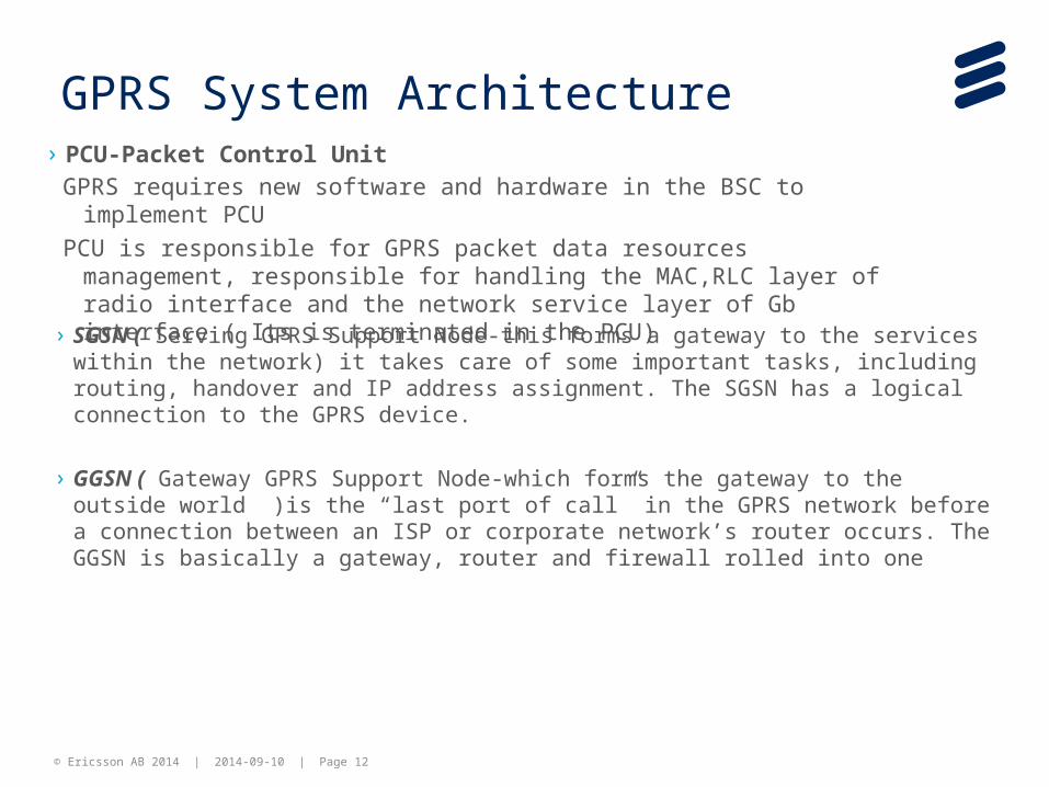
GPRS requires new software and hardware in the BSC to implement PCU
PCU is responsible for GPRS packet data resources management, responsible for handling the MAC,RLC layer of radio interface and the network service layer of Gb interface ( Its is terminated in the PCU)
› PCU-Packet Control Unit
› SGSN ( Serving GPRS Support Node-this forms a gateway to the services within the network) it takes care of some important tasks, including routing, handover and IP address assignment. The SGSN has a logical connection to the GPRS device.
› GGSN ( Gateway GPRS Support Node-which forms the gateway to the outside world )is the “last port of call” in the GPRS network before a connection between an ISP or corporate network’s router occurs. The GGSN is basically a gateway, router and firewall rolled into one
© Ericsson AB 2014 | 2014-09-10 | Page 13
SS7BTS
BSC
MSCVLR
HLRAuC
GMSC
BSS
PSTN
NSS
AE
CD
PSTNAbis
B
H
MS
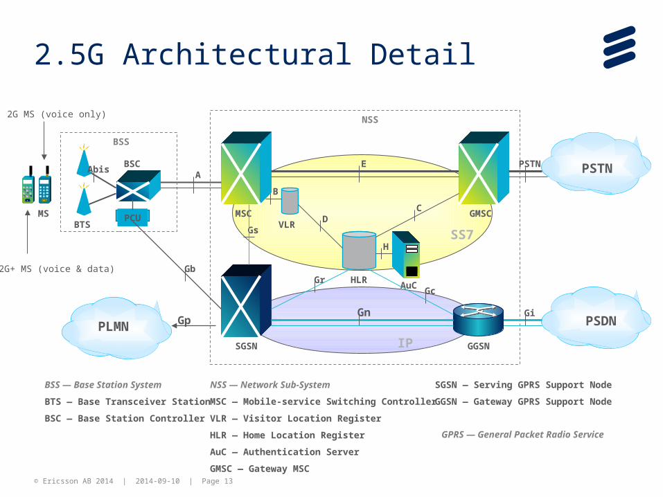
BSS — Base Station System
BTS — Base Transceiver Station
BSC — Base Station Controller
NSS — Network Sub-System
MSC — Mobile-service Switching Controller
VLR — Visitor Location Register
HLR — Home Location Register
AuC — Authentication Server
GMSC — Gateway MSC
2.5G Architectural Detail
SGSN — Serving GPRS Support Node
GGSN — Gateway GPRS Support Node
GPRS — General Packet Radio Service
IP
2G+ MS (voice & data)
PSDNGi
SGSN
GrGb
Gs
GGSN
Gc
Gn
2G MS (voice only)
PCU
PLMN Gp
© Ericsson AB 2014 | 2014-09-10 | Page 14
Interface for GPRS and EDGEInterfa
ceBetween Description
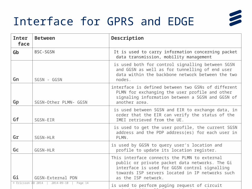
Gb BSC-SGSN It is used to carry information concerning packet data transmission, mobility management
Gn SGSN - GGSN
is used both for control signalling between SGSN and GGSN as well as for tunnelling of end user data within the backbone network between the two nodes.
Gp SGSN-Other PLMN- GGSN
interface is defined between two GSNs of different PLMN for exchanging the user profile and other signaling information between a SGSN and GGSN of another area.
Gf SGSN-EIR is used between SGSN and EIR to exchange data, in order that the
EIR can verify the status of the IMEI retrieved from the UE.
Gr SGSN-HLR is used to get the user profile, the current SGSN address and the
PDP address(es) for each user in PLMN.
Gc GGSN-HLRis used by GGSN to query user's location and profile to update its
location register.
Gi GGSN-External PDN
This interface connects the PLMN to external public or private packet data networks. The Gi interface is used for GGSN control signalling towards ISP servers located in IP networks such as the ISP network.
Gs SGSN-MSC/VLRis used to perform paging request of circuit switched GSM call for
combined attachment procedure.
Gd SMS-GATEWAY(SMS-GMSC)- SGSN is used to exchange short message service (SMS) messages.
© Ericsson AB 2014 | 2014-09-10 | Page 15
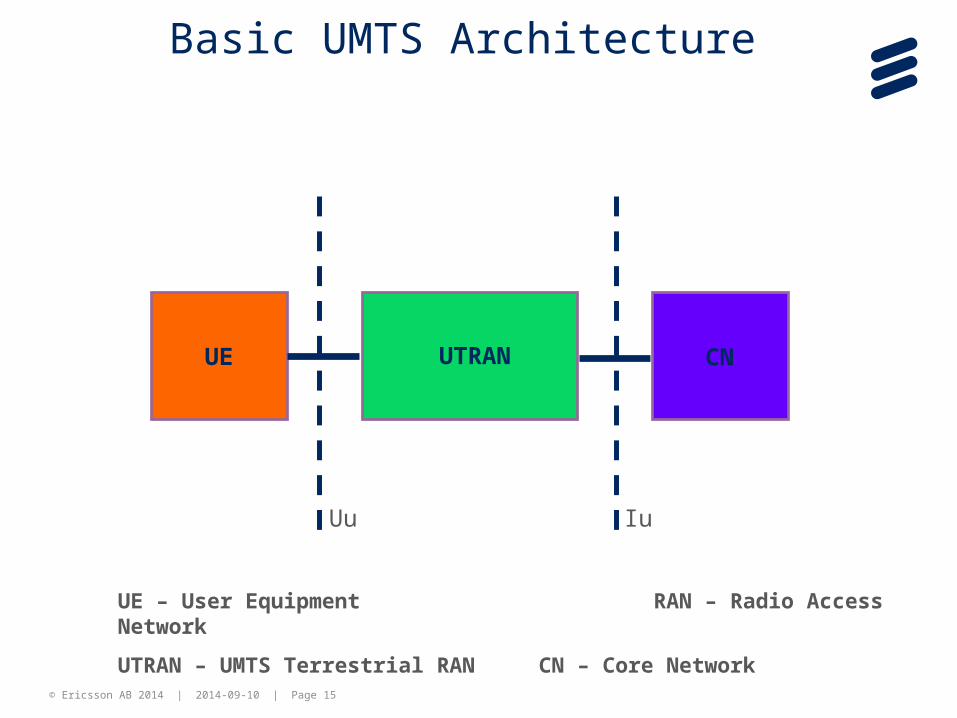
UE UTRAN CN
Uu Iu
UE – User Equipment RAN – Radio Access Network
UTRAN – UMTS Terrestrial RAN CN – Core Network
Basic UMTS Architecture
© Ericsson AB 2014 | 2014-09-10 | Page 16
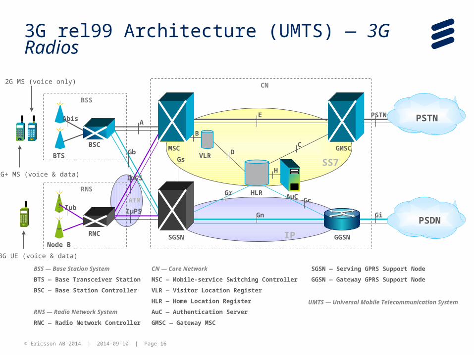
3G rel99 Architecture (UMTS) — 3G Radios
SS7
IP
BTS
BSCMSC
VLR
HLRAuC
GMSC
BSS
SGSN GGSN
PSTN
PSDN
CN
CD
GcGr
Gn Gi
Abis
Gs
B
H
BSS — Base Station System
BTS — Base Transceiver Station
BSC — Base Station Controller
RNS — Radio Network System
RNC — Radio Network Controller
CN — Core Network
MSC — Mobile-service Switching Controller
VLR — Visitor Location Register
HLR — Home Location Register
AuC — Authentication Server
GMSC — Gateway MSC
SGSN — Serving GPRS Support Node
GGSN — Gateway GPRS Support Node
AE PSTN
2G MS (voice only)
2G+ MS (voice & data)
UMTS — Universal Mobile Telecommunication System
Gb
3G UE (voice & data)
Node B
RNC
RNS
Iub
IuCS
ATM
IuPS

© Ericsson AB 2014 | 2014-09-10 | Page 17
Mobile Softswitch Definition
Classic MSC(Control and Switching)
MSC Server(Control)
Mobile Media Gateway(Switching)
Mobile Softswitch SolutionClassic MSC Solution
MSC
MSC-S
MGw
Control Layer
Connectivity Layer
Classic circuit-switched network
TDM
MSC
MSC MSC
MSC MSC
Layered Architecture network
IP
MSC-S
MGw
MGw MGw
MGw MGw
Classic MSC(Control and Switching)
MSC Server(Control)
Mobile Media Gateway(Switching)
Mobile Softswitch SolutionClassic MSC Solution
MSCMSC
MSC-SMSC-S
MGwMGw
Control Layer
Connectivity Layer
Classic circuit-switched network
TDM
MSC
MSC MSC
MSC MSC
Layered Architecture network
IP
MSC-S
MGw
MGw MGw
MGw MGw
Control Layer
Connectivity Layer
Control Layer
Connectivity Layer
Classic circuit-switched network
TDM
MSC
MSC MSC
MSC MSC
Classic circuit-switched network
TDM
MSC
MSC MSC
MSC MSC
TDM
MSCMSC
MSCMSC MSCMSC
MSCMSC MSCMSC
Layered Architecture network
IP
MSC-S
MGw
MGw MGw
MGw MGw
Layered Architecture network
IP
MSC-S
MGw
MGw MGw
MGw MGw
IP
MSC-SMSC-S
MGwMGw
MGwMGw MGwMGw
MGwMGw MGwMGw
Normal MSC uses group switch and ET devices to switch calls. All voice and CS data use the group switch as the payload transport.
In MSC-S the voice/CS data transport functionality is performed by MGW. The MSC-S only controls the MGW's switching function.
© Ericsson AB 2014 | 2014-09-10 | Page 18
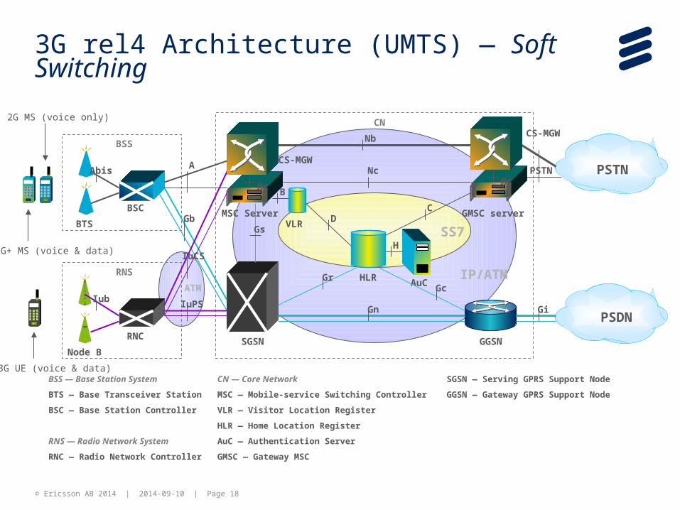
3G rel4 Architecture (UMTS) — Soft Switching
SS7
IP/ATM
BTS
BSCMSC Server
VLR
HLRAuC
GMSC server
BSS
SGSN GGSN
PSTN
PSDN
CN
CD
GcGr
Gn Gi
Gb
Abis
Gs
B
H
BSS — Base Station System
BTS — Base Transceiver Station
BSC — Base Station Controller
RNS — Radio Network System
RNC — Radio Network Controller
CN — Core Network
MSC — Mobile-service Switching Controller
VLR — Visitor Location Register
HLR — Home Location Register
AuC — Authentication Server
GMSC — Gateway MSC
SGSN — Serving GPRS Support Node
GGSN — Gateway GPRS Support Node
ANc
2G MS (voice only)
2G+ MS (voice & data)
Node B
RNC
RNS
Iub
IuCS
IuPS
3G UE (voice & data)
Mc
CS-MGW
CS-MGWNb
PSTNMc
ATM
© Ericsson AB 2014 | 2014-09-10 | Page 19
3G-BLOCK
› MGW (Media Gateway )acts as an interface between the different Core Network domains and the 2G and 3G RANs.
› MSC-S(MSC-SERVER) is responsible for setting up, routing, and supervising calls to and from the mobile subscriber (mobility management, handover, ect).
› Node B functions:Call Processing,Radio access,Performance Monitoring,Network interface,Random Access detection
› RNC functions:Radio Resource Management,User Mobility Handling,Interfaces
© Ericsson AB 2014 | 2014-09-10 | Page 20
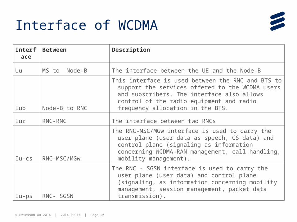
Interface of WCDMA
Interface
Between Description
Uu MS to Node-B The interface between the UE and the Node-B
Iub Node-B to RNC
This interface is used between the RNC and BTS to support the services offered to the WCDMA users and subscribers. The interface also allows control of the radio equipment and radio frequency allocation in the BTS.
Iur RNC-RNC The interface between two RNCs
Iu-cs RNC-MSC/MGw
The RNC-MSC/MGw interface is used to carry the user plane (user data as speech, CS data) and control plane (signaling as information concerning WCDMA-RAN management, call handling, mobility management).
Iu-ps RNC- SGSN
The RNC - SGSN interface is used to carry the user plane (user data) and control plane (signaling, as information concerning mobility management, session management, packet data transmission).
© Ericsson AB 2014 | 2014-09-10 | Page 21 21
MME
S1-MME S1-U
LTE
IP networks
eNodeB
SGSN
Iu CPGb
2G 3G
S3
BSC
BTS
RNC
Node B
HLR/HSS
PCRF
Iu UP
S11
Gr
S10
S6a
SGi
X2
Iur
S7
Non-3GPP access
S2a/b
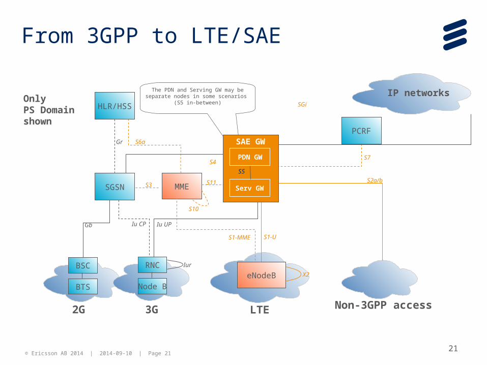
The PDN and Serving GW may be separate nodes in some scenarios
(S5 in-between)Only PS Domain shown
S4
From 3GPP to LTE/SAE
PDN GW
SAE GW
Serv GW
S5
© Ericsson AB 2014 | 2014-09-10 | Page 22
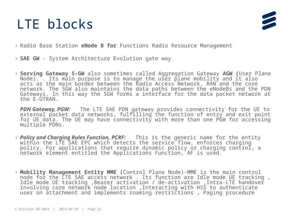
LTE blocks
› Radio Base Station eNode B for Functions Radio Resource Management
› SAE GW - System Architecture Evolution gate way
› Serving Gateway S-GW also sometimes called Aggregation Gateway AGW (User Plane Node). . Its main purpose is to manage the user plane mobility and it also acts as the main border between the Radio Access Network, RAN and the core network. The SGW also maintains the data paths between the eNodeBs and the PDN Gateways. In this way the SGW forms a interface for the data packet network at the E-UTRAN.
PDN Gateway, PGW: The LTE SAE PDN gateway provides connectivity for the UE to external packet data networks, fulfilling the function of entry and exit point for UE data. The UE may have connectivity with more than one PGW for accessing multiple PDNs.
› Policy and Charging Rules Function, PCRF: This is the generic name for the entity within the LTE
SAE EPC which detects the service flow, enforces charging policy. For applications that require dynamic policy or charging control, a network element entitled the Applications Function, AF is used.
› Mobility Management Entity MME (Control Plane Node)-MME is the main control node for the LTE SAE access network . Its function are Idle mode UE tracking , Idle mode UE tracking ,Bearer activation / de-activation ,Intra-LTE handover involving core network node location ,Interacting with HSS to authenticate user on attachment and implements roaming restrictions , Paging procedure
© Ericsson AB 2014 | 2014-09-10 | Page 23
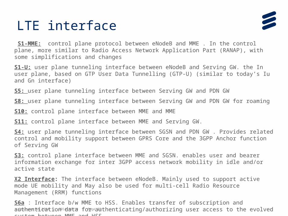
LTE interface S1-MME: control plane protocol between eNodeB and MME . In the control plane, more similar to Radio Access Network Application Part (RANAP), with some simplifications and changes
S1-U: user plane tunneling interface between eNodeB and Serving GW. the In user plane, based on GTP User Data Tunnelling (GTP-U) (similar to today’s Iu and Gn interface)
S5: user plane tunneling interface between Serving GW and PDN GW
S8: user plane tunneling interface between Serving GW and PDN GW for roaming
S10: control plane interface between MME and MME
S11: control plane interface between MME and Serving GW.
S4: user plane tunneling interface between SGSN and PDN GW . Provides related control and mobility support between GPRS Core and the 3GPP Anchor function of Serving GW
S3: control plane interface between MME and SGSN. enables user and bearer information exchange for inter 3GPP access network mobility in idle and/or active state
X2 Interface: The interface between eNodeB. Mainly used to support active mode UE mobility and May also be used for multi-cell Radio Resource Management (RRM) functions
S6a : Interface b/w MME to HSS. Enables transfer of subscription and authentication data for authenticating/authorizing user access to the evolved system between MME and HSS.
Sgi : Interface between SAE GW to IP network. Packet data network may be an operator external public or private packet data network or an intra operator packet data network, e.g. for provision of IMS services.

© Ericsson AB 2014 | 2014-09-10 | Page 24
SDPCCN
HLR
Core Node
MSC
GGSN
SGSN
VXML IVR0..n
AIR
AF
EMA
MINSET
VS
LAPU
PaymentGateway
EXT
EMM
STP
Charging System
INS
SMSC
CAPV3
Gx / Gy
Sigtran
CIP-IP
ISUP
XML/http
CS1 +
SMPPXML/RPC
XML/http
EMAP
XML/RPC
XML/http
CAI
DNS
DNS etop-up
Online Recharge
CAI
DNS
MML
CAI/PAMIXML/http
CC API
PAMI
FTP
XML/http
© Ericsson AB 2014 | 2014-09-10 | Page 25
Charging System Elements
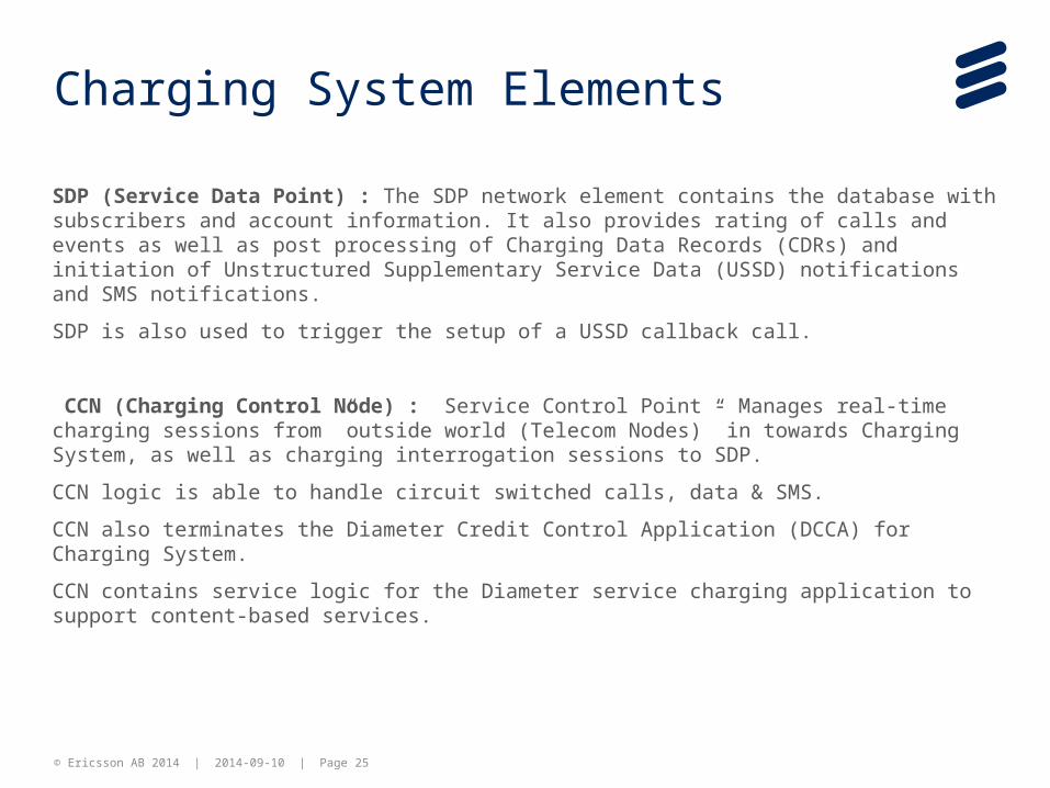
SDP (Service Data Point) : The SDP network element contains the database with subscribers and account information. It also provides rating of calls and events as well as post processing of Charging Data Records (CDRs) and initiation of Unstructured Supplementary Service Data (USSD) notifications and SMS notifications.
SDP is also used to trigger the setup of a USSD callback call.
CCN (Charging Control Node) : Service Control Point - Manages real-time charging sessions from ”outside world (Telecom Nodes)” in towards Charging System, as well as charging interrogation sessions to SDP.
CCN logic is able to handle circuit switched calls, data & SMS.
CCN also terminates the Diameter Credit Control Application (DCCA) for Charging System.
CCN contains service logic for the Diameter service charging application to support content-based services.

© Ericsson AB 2014 | 2014-09-10 | Page 26
AIR (Account Information and Refill System) :
AIR handles external integration of user communication and administrative network elements.
AIR has three function groups; refill function, adjustment function, and the inquiry and update function from 3rd party Application
AIR handles account information in the form of inquiries and account administration.
It supports a number of file-based batch jobs for making bulk adjustments, promotions, and refills.
AIR can handle multiple Voucher Servers (VSs).
AF (Account Finder) : AF is a network element that provides SDP id information for subscriber accounts in the system. AF enables centralized management of multiple SDPs.
AF is always collocated with AIR.
VS (Voucher Server) : VS is responsible for the administration and storage of vouchers.
Charging System Elements
© Ericsson AB 2014 | 2014-09-10 | Page 27
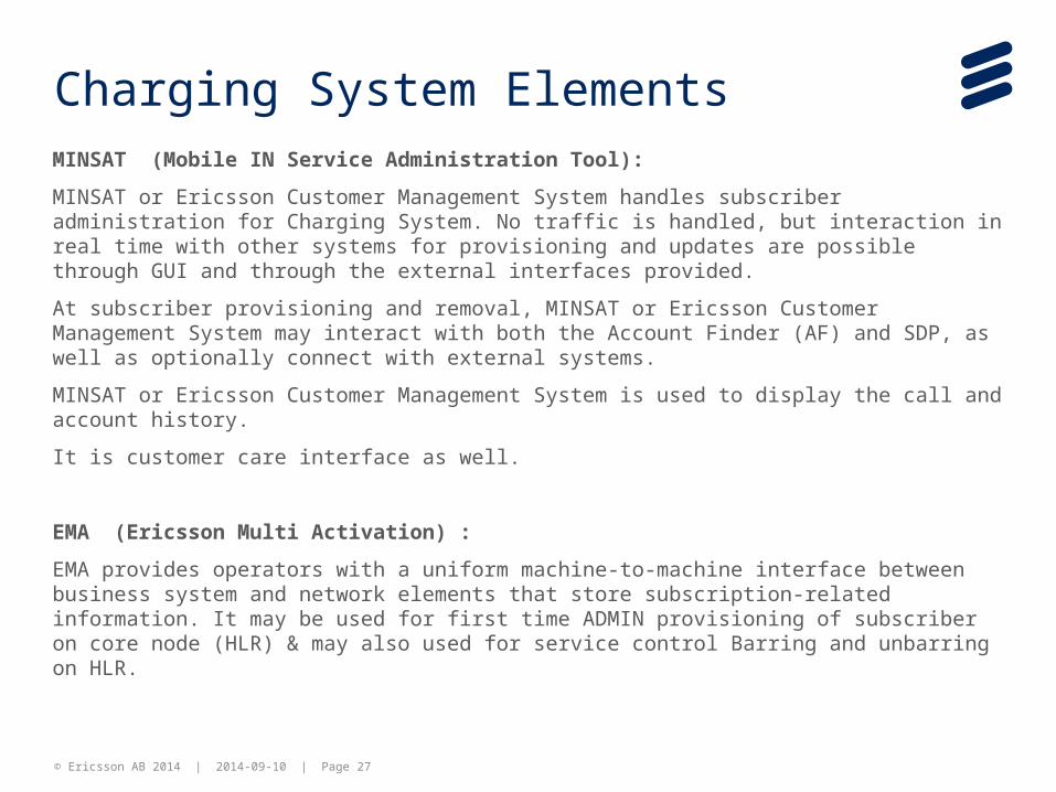
MINSAT (Mobile IN Service Administration Tool):
MINSAT or Ericsson Customer Management System handles subscriber administration for Charging System. No traffic is handled, but interaction in real time with other systems for provisioning and updates are possible through GUI and through the external interfaces provided.
At subscriber provisioning and removal, MINSAT or Ericsson Customer Management System may interact with both the Account Finder (AF) and SDP, as well as optionally connect with external systems.
MINSAT or Ericsson Customer Management System is used to display the call and account history.
It is customer care interface as well.
EMA (Ericsson Multi Activation) :
EMA provides operators with a uniform machine-to-machine interface between business system and network elements that store subscription-related information. It may be used for first time ADMIN provisioning of subscriber on core node (HLR) & may also used for service control Barring and unbarring on HLR.
Charging System Elements
© Ericsson AB 2014 | 2014-09-10 | Page 28
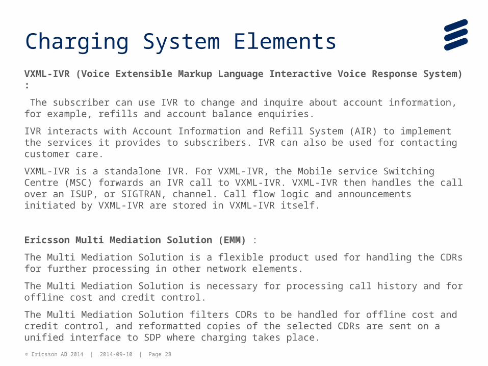
VXML-IVR (Voice Extensible Markup Language Interactive Voice Response System) :
The subscriber can use IVR to change and inquire about account information, for example, refills and account balance enquiries.
IVR interacts with Account Information and Refill System (AIR) to implement the services it provides to subscribers. IVR can also be used for contacting customer care.
VXML-IVR is a standalone IVR. For VXML-IVR, the Mobile service Switching Centre (MSC) forwards an IVR call to VXML-IVR. VXML-IVR then handles the call over an ISUP, or SIGTRAN, channel. Call flow logic and announcements initiated by VXML-IVR are stored in VXML-IVR itself.
Ericsson Multi Mediation Solution (EMM) :
The Multi Mediation Solution is a flexible product used for handling the CDRs for further processing in other network elements.
The Multi Mediation Solution is necessary for processing call history and for offline cost and credit control.
The Multi Mediation Solution filters CDRs to be handled for offline cost and credit control, and reformatted copies of the selected CDRs are sent on a unified interface to SDP where charging takes place.
Charging System Elements

Slide title minimum 32 pt
(32 pt makes 2 rows
Text and bullet level 1 minimum 24 pt
Bullets level 2-5minimum 20 pt
!"#$%&'()*+,-./0123456789:;<=>?@ABCDEFGHIJKLMNOPQRSTUVWXYZ[\]^_`abcdefghijklmnopqrstuvwxyz{|}~¡¢£¤¥¦§¨©ª«¬®¯°±²³´¶·¸¹º»¼½ÀÁÂÃÄÅÆÇÈËÌÍÎÏÐÑÒÓÔÕÖ×ØÙÚÛÜÝÞßàáâãäåæçèéêëìíîïðñòóôõö÷øùúûüýþÿĀāĂăąĆćĊċČĎďĐđĒĖėĘęĚěĞğĠġĢģĪīĮįİıĶķĹĺĻļĽľŁłŃńŅņŇňŌŐőŒœŔŕŖŗŘřŚśŞşŠšŢţŤťŪūŮůŰűŲųŴŵŶŷŸŹźŻżŽžƒȘșˆˇ˘˙˚˛˜˝ẀẁẃẄẅỲỳ–—‘’‚“”„†‡•…‰‹›⁄€™−≤≥fifl
ĀĀĂĂĄĄĆĆĊĊČČĎĎĐĐĒĒĖĖĘĘĚĚĞĞĠĠĢĢĪĪĮĮİĶĶĹĹĻĻĽĽŃŃŅŅŇŇŌŌŐŐŔŔŖŖŘŘŚŚŞŞŢŢŤŤŪŪŮŮŰŰŲŲŴŴŶŶŹŹŻŻȘș
ΆΈΉΊΌΎΏΐΑΒΓΕΖΗΘΙΚΛΜΝΞΟΠΡΣΤΥΦΧΨΪΫΆΈΉΊΰαβγδεζηθικλνξορςΣΤΥΦΧΨΩΪΫΌΎΏ
ЁЂЃЄЅІЇЈЉЊЋЌЎЏАБВГДЕЖЗИЙКЛМНОПРСТУФХЦЧШЩЪЫЬЭЮЯАБВГДЕЖЗИЙКЛМНОПРСТУФХЦЧШЩЪЫЬЭЮЯЁЂЃЄЅІЇЈЉЊЋЌЎЏѢѢѲѲѴѴҐҐәǽẀẁẂẃẄẅỲỳ№
Do not add objects or text in the footer area
Ericsson Internal | 2011-02-28 | Page 29