introduction to manual and computer aided drawing 2011_2012 rev c
DESCRIPTION
Introductory notes on design drawings for Civil Engineering.TRANSCRIPT

University of Strathclyde Department of Civil Engineering Civil Engineering Design Projects - CL114
1 Andrew Briggs Rev C: 29/09/11
INTRODUCTION TO MANUAL AND COMPUTER AIDED DRAWING
Section Page SUMMARY 2 ENGINEERING DRAWINGS – PRESENTATION 2
Paper sizes 3 Drawing sheets 4 Lines, lettering and hatching 4 Scale 6 Projection 7
ENGINEERING DRAWINGS – CONTENT 8 MANUAL DRAWING 11 COMPUTER AIDED DRAWING 12 Introduction 12 Drawing Exercises 12 Coursework assignments 13 Drawing with AutoCad 13 Getting Started 16 AUTOCAD – FURTHER LEARNING 17 REFERENCES 18 Exercise 1 19 Exercise 2 23 Exercise 3 27 Exercise 4 31 Exercise 5 37 Assignment 1 – Drawing No CL114/05 Assignment 2 – Drawing No 34897/202

University of Strathclyde Department of Civil Engineering Civil Engineering Design Projects - CL114
2 Andrew Briggs Rev C: 29/09/11
SUMMARY This part of the class covers the basic concepts behind the production of technical drawings in the civil and structural engineering industry. Advice is given about the presentation and content of two dimensional drawings followed by tutorials to provide an introduction to computer aided drawing using Autocad. A good reference book is ‘An Introduction to Drawing for Civil Engineers’ by Ahmed Elsheikh. It is out of print but a second hand copy might be available from Amazon and it is available in the Library. The Library has other books about civil engineering drawing. ENGINEERING DRAWINGS – PRESENTATION Engineering drawings enable ideas to be expressed and communicated. To achieve this, they should be prepared following standard rules and conventions. In general, three dimensional objects such as buildings, bridges, roads, etc, are represented by two dimensional drawings which contain sufficient information to enable the project to be constructed. Drawings should be clear with no possibility of miss interpretation, i.e. unnecessary details should be avoided and the drawing should only convey the information for which it is required. The relevant British Standard is BS 1192. Paper sizes Drawings should be sized to suit paper sizes of A4, A3, A2, A1 or A0. An A3 sheet is twice the area of an A4 sheet. An A2 sheet is twice the area of an A3 sheet, and so forth. A1 drawings are quite large and it is often preferable to work with A3 sized paper prints. Lines drawn on an A1 sheet are reduced in length be half if the drawing is printed at A3 size and therefore it is possible to scale dimensions from the print relatively easily. A0 size drawings were common when drawings were prepared by hand, but their large size makes them difficult to handle or lay down on a normal sized desk. Since the advent of computer aided drafting, A0 size drawings are generally avoided because it is possible to select a scale that enables all the information to be contained on an A1 size drawing. A2 size drawings are rarely used by civil engineers.

University of Strathclyde Department of Civil Engineering Civil Engineering Design Projects - CL114
3 Andrew Briggs Rev C: 29/09/11
The dimensions of the different sizes of paper are as follows:
Paper Designation Size (mm) A4 210 x 297 A3 297 x 420 A2 420 x 594
A1 594 x 841 A0 841 x 1189
Drawing sheets Engineering drawings should be drawn on drawing sheets that are one of the standard paper sizes. Drawing sheets have a border, title box and the larger sizes also have a box for notes. Examples of A4 and A1 drawing sheet are shown below. The title box contains the project title, drawing title and drawing number, plus details of the scale, names of the people who prepared and checked the drawing, the revision and its status.
A4 Drawing Sheet

University of Strathclyde Department of Civil Engineering Civil Engineering Design Projects - CL114
4 Andrew Briggs Rev C: 29/09/11
A1 Drawing Sheet Templates for A4 to A1 size drawing sheets with the Department of Civil Engineering title can be downloaded from the L drive in the folder, L:\CivilEng\Drawings and CAD\Drawing sheet templates. These templates are available as both pdf and dwg files. The pdf templates can be used to print drawing sheets for hand sketches etc. The dwg files are used with Autocad. Drawings should be folded so that the title box is visible. BS 1192: Part 1:1984 shows how to fold the different sizes of drawing sheet. Lines, lettering, and hatching To produce neat drawings that are legible and easily interpreted requires the draughtsman to use different types of line and line thicknesses (line weight in Autocad) to represent different parts of the object being drawn. Drawing No CL114/01 below summarises the commonly used line types and gives recommendations for the line thicknesses to use with Autocad. It is important to use consistent line thicknesses throughout a drawing and for similar drawings on a project, but the actual thicknesses chosen will depend on the sizes and types of drawings/details being prepared. There is an art to using appropriate line thicknesses to create legible drawings.

University of Strathclyde Department of Civil Engineering Civil Engineering Design Projects - CL114
5 Andrew Briggs Rev C: 29/09/11

University of Strathclyde Department of Civil Engineering Civil Engineering Design Projects - CL114
6 Andrew Briggs Rev C: 29/09/11
If preparing drawings by hand using a pencil and paper, you should still aim to have different line thicknesses, but this requires an element of practice and skill. Dimension lines should be as shown on drawing No CL114/01 with the text read either from below or looking from the right side of the drawing. Note that thin lines are used for the dimensions so that the outline of the object drawn is more prominent and stands out. There are standard patterns for hatching cross sections through different types of material. Drawing No CL114/01 shows the patterns for concrete, steel, brickwork and concrete blockwork. The reference below each pattern is the Autocad pattern reference. Text should be the same font throughout the drawing and for large drawings, it is prudent to select a point size that remains legible if the drawing is printed at a reduced size, i.e. an A1 drawing printed at A3 size. Scale The objects drawn for civil and structural engineering projects are generally considerably larger than paper drawing sheets. Conversely, in the electronics industry, components might be very small. Hence most engineering drawings are not drawn full size. Instead the objects are drawn to a suitable scale so that all the information required to manufacture or construct it is legible and can be fitted onto a drawing sheet. Civil and structural engineering drawings would generally only use reduction scales. The scales should be sensible numbers and the standard ratios used are as follows:
1:2 1:5 1:10 1:20 1:50 1:100 1:200 1:500 1:1000 1:2000 1:5000
A scale of 1:100 means that the drawing is 1/100th the size of the object being drawn. Plans and elevations for buildings are typically drawn to a scale of 1:100 or 1:50 whereas details might be drawn at a scale of 1:20 or 1:10. Therefore if a drawing contains plans and details, different parts of the drawing may be drawn to different scales.

University of Strathclyde Department of Civil Engineering Civil Engineering Design Projects - CL114
7 Andrew Briggs Rev C: 29/09/11
Projection Two types of projection are used, either orthogonal or pictorial. Pictorial projection creates a view that appears to be three dimensional. Isometric, oblique and perspective are different types of pictorial projection. Whilst this type of view makes it easy to visualise an object, it is often not possible to include all details, dimensions, etc. that are required to manufacture or construct it. For instance, the picture below shows a rectangular block with a hole in it. But it is not possible to determine from this drawing whether or not the hole is the full width of the block or if the hidden part of the block is the same shape as the visible part.
PICTORIAL PROJECTION
Orthogonal projection is the preferred way to present drawn information so that an object can be manufactured or constructed from it. An orthogonal drawing will provide two dimensional views of the object plus sections and details. Orthogonal drawings are generally prepared using first angle projection as shown below. From the three views drawn below, it is now possible to confirm that the hole is the full width of the block and the shape of the block is fully defined.
FIRST ANGLE PROJECTION

University of Strathclyde Department of Civil Engineering Civil Engineering Design Projects - CL114
8 Andrew Briggs Rev C: 29/09/11
ENGINEERING DRAWINGS – CONTENT The information on a drawing will depend on the stage of the project and the purpose of the drawing. This can be summarised as ‘The minimum amount of information and detail which, clearly and unambiguously, fully define the requirements’. The following notes are based on drawings for a building structure, but similar principles apply when preparing drawings for other types of project. At the preliminary stages of a project, general arrangement drawings will generally be drawn to a small scale, which show the overall size and shape but no detail is included. This type of drawing can be used for discussion, perhaps the advantages and disadvantages of two options are being discussed. But the drawings do not contain sufficient information to enable an accurate estimate of the quantities of materials or cost to be prepared or to construct the project. As a design progresses, the general arrangement drawings become more detailed and include dimensions or co-ordinates to position every element and the sizes of elements are included. At this stage, the drawings contain sufficient information to enable an accurate estimate to be made of the quantities of materials that are required to construct the project. The drawings for a steel framed building for instance would show the section sizes of each element. On a reinforced concrete frame, the dimensions and thicknesses of beams, columns and slabs would be specified. At the construction stage of the project, the drawings must contain all the information necessary to construct every element of the project. For a reinforced concrete structure, drawings showing the reinforcing bars in each beam, column and slab are required. Examples of reinforcement drawings are included in the project drawings that can be downloaded from the L drive in the folder L:\CivilEng\Drawings and CAD\Project Drawings. Drawings for the construction stage of a project require a considerable amount of time to prepare and for checking. Accurate construction drawings are essential. The cost of carrying out modifications on site to rectify errors due to inaccurate setting out or other information on a drawing can be very high. Many structural components are manufactured in a factory and are assembled on site, i.e. there is unlikely to be the equipment on site necessary to carry out modifications if components do not fit together. When preparing construction drawings, a useful approach is to study them and carry out a ‘could I build it check’, i.e. can you determine the position, size, specification and details for every element without asking advice from the draughtsman or designer. The drawings for a building will comprise plans at each level where there are primary structural elements. For instance, the foundations, ground floor, first floor and so on up to the roof level. A system of gridlines will be established
University of Strathclyde Department of Civil Engineering Civil Engineering Design Projects - CL114
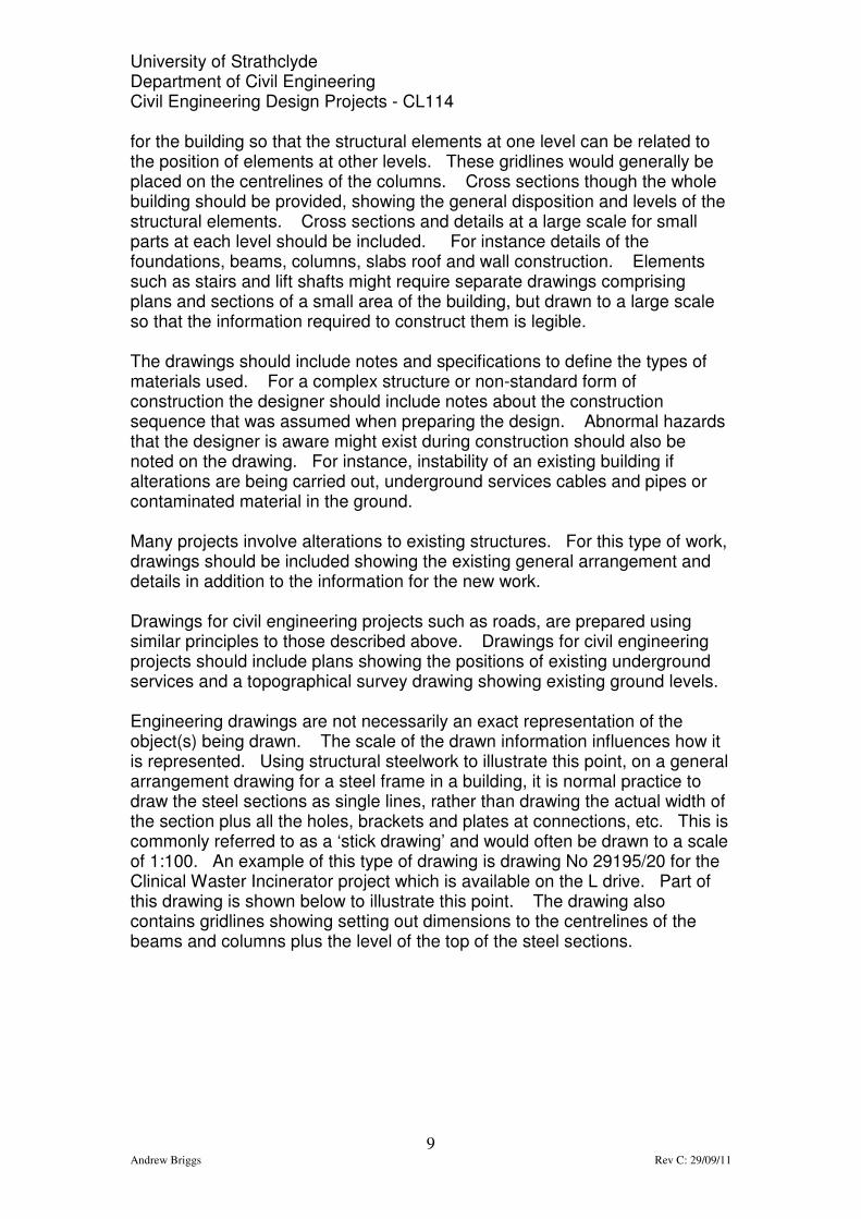
9 Andrew Briggs Rev C: 29/09/11
for the building so that the structural elements at one level can be related to the position of elements at other levels. These gridlines would generally be placed on the centrelines of the columns. Cross sections though the whole building should be provided, showing the general disposition and levels of the structural elements. Cross sections and details at a large scale for small parts at each level should be included. For instance details of the foundations, beams, columns, slabs roof and wall construction. Elements such as stairs and lift shafts might require separate drawings comprising plans and sections of a small area of the building, but drawn to a large scale so that the information required to construct them is legible. The drawings should include notes and specifications to define the types of materials used. For a complex structure or non-standard form of construction the designer should include notes about the construction sequence that was assumed when preparing the design. Abnormal hazards that the designer is aware might exist during construction should also be noted on the drawing. For instance, instability of an existing building if alterations are being carried out, underground services cables and pipes or contaminated material in the ground. Many projects involve alterations to existing structures. For this type of work, drawings should be included showing the existing general arrangement and details in addition to the information for the new work. Drawings for civil engineering projects such as roads, are prepared using similar principles to those described above. Drawings for civil engineering projects should include plans showing the positions of existing underground services and a topographical survey drawing showing existing ground levels. Engineering drawings are not necessarily an exact representation of the object(s) being drawn. The scale of the drawn information influences how it is represented. Using structural steelwork to illustrate this point, on a general arrangement drawing for a steel frame in a building, it is normal practice to draw the steel sections as single lines, rather than drawing the actual width of the section plus all the holes, brackets and plates at connections, etc. This is commonly referred to as a ‘stick drawing’ and would often be drawn to a scale of 1:100. An example of this type of drawing is drawing No 29195/20 for the Clinical Waster Incinerator project which is available on the L drive. Part of this drawing is shown below to illustrate this point. The drawing also contains gridlines showing setting out dimensions to the centrelines of the beams and columns plus the level of the top of the steel sections.

University of Strathclyde Department of Civil Engineering Civil Engineering Design Projects - CL114
10 Andrew Briggs Rev C: 29/09/11
Part copy of drawing No 29195/20
Example of a General Arrangement ‘stick drawing’ drawn to a scale of 1:100
The cross sections through the steel frame of a building are often drawn to a larger scale, 1:50 or 1:20, and at this size, the full width of the steel sections is drawn. But the flanges are drawn as a single line instead of showing lines for both faces/edges. Drawing No 29195/21 for the Clinical Waste Incinerator project is an example of this type of drawing. Part of this drawing is shown below to illustrate this point.
Part copy of drawing No 29195/21
Example of a cross section through a building drawn to a scale of 1:50

University of Strathclyde Department of Civil Engineering Civil Engineering Design Projects - CL114
11 Andrew Briggs Rev C: 29/09/11
Details for small parts are drawn to larger scales, e.g. 1:10 or 1:5 and at this size it is possible to include information such as bolt holes and show the outline of the steel section, i.e. the thickness of the flanges and web. Drawing No 29195/22 is an example of a drawing with details drawn at a large scale. Part of this drawing is shown below to illustrate this type of detail.
Part copy of drawing No 29195/22
Example of a detail for a small part (a base plate) drawn to a scale of 1:10
Using the general arrangement drawings, sections and details, the steelwork fabricator will prepare detailed drawings for each individual steel element prior to manufacturing them. The above notes provide a summary of the main points to consider when preparing a set of drawings for a project. You should study the sample pdf drawings available to download from the Project Drawings on the L drive to understand in more detail how the information required to construct a project is conveyed by 2D drawings. MANUAL DRAWING Large drawings with the line work and text prepared using ink pens are now rarely produced, but many engineers still prepare A4 or A3 size drawings and sketches which are drawn using a pencil. Small drawing boards are available to suit A4 and A3 sizes of paper, but it is possible to prepare reasonably accurate drawings using only a pad of paper or drawing sheet plus a scale ruler and set squares (45, 60 and adjustable). A rolling ruler is useful when drawing parallel lines. Different grades of pencil are used for different line types. A hard lead, e.g. 4H will produce faint thin construction lines. An H lead is suitable for finishing the outlines on a technical drawing and softer leads such as B or 2B are suitable for freehand sketching.

University of Strathclyde Department of Civil Engineering Civil Engineering Design Projects - CL114
12 Andrew Briggs Rev C: 29/09/11
COMPUTER AIDED DRAWING Introduction The programme we will be using is Autocad Civil 3D which is available on the computers in the labs in the Colville Building in rooms 3.09, 3.09A and 3.09B and other locations around the University. Autocad Civil 3D is a very comprehensive programme capable of producing 2D and 3D drawings, rendered drawings, perspectives, animations, etc. You may download a copy of the Autocad software for use on your own computer and details are given in the references at the end of these notes. This class and the coursework will provide an introduction to 2D drawings. In the second and third years, guidance will be given about using Autocad for surveying and 3D terrain modelling. These classes will provide sufficient advice to enable you to prepare relatively simple engineering drawings and details for civil and structural engineering projects. It is recommended that students develop skills in Autocad beyond the level of the coursework, by working in their own time on the additional tutorial examples that are provided. Autocad skills will generally help when seeking vacation employment with Civil and Structural engineering consultancies and after graduation. There will be a range of abilities at using Autocad when the class starts because some students will have used it at school whereas others will be new to it. Therefore, students will be able to start at a level and progress at a rate that suits their experience. There will be an introductory lecture about Autocad in week 2, and it is recommended that all students attend this lecture including those that are already proficient at using it. Thereafter, tutorials will be held in the computer labs on Tuesday afternoons on weeks 3 to 6 when advice will be available to help you progress. You should work on the drawing exercises and coursework assignments before attending these tutorial sessions so that you have a list of questions to discuss each week. It is recommended that you work in small groups of 5 to 6 students on the exercises and coursework assignments so that you can provide support and assistance to each other. Drawing Exercises Five drawing exercises are provided to enable students who are new to Autocad to develop the basic skills required to complete the two assignments. These exercises will not be marked and do not form part of the coursework. Students who have used Autocad previously can select which exercises they require to complete to learn new skills or they might be able to start the coursework assignments immediately. As discussed earlier, after completing the assignments, it is recommended that you continue to develop additional Autocad skills. In particular you

University of Strathclyde Department of Civil Engineering Civil Engineering Design Projects - CL114
13 Andrew Briggs Rev C: 29/09/11
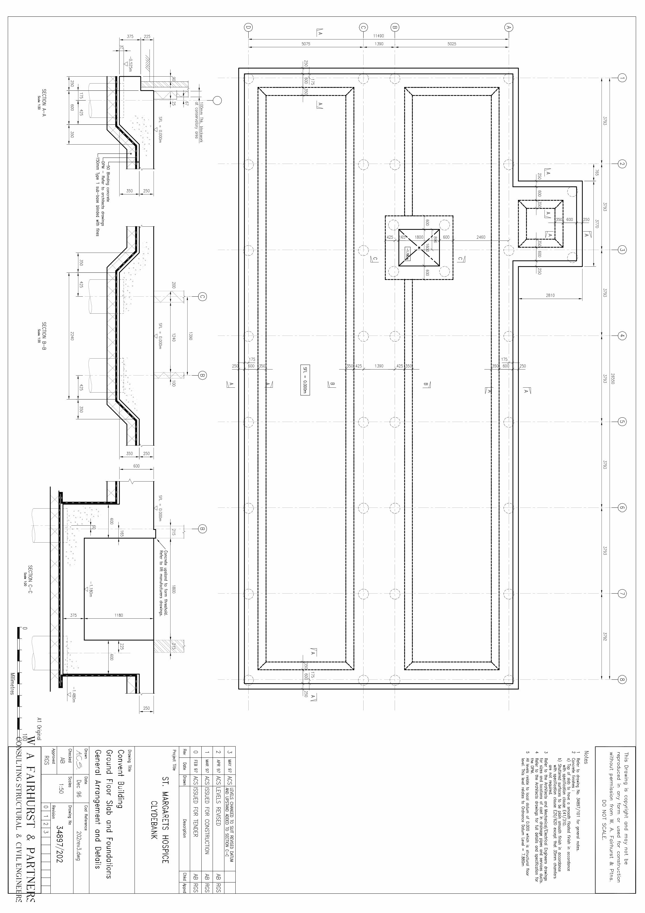
should develop your skills using layers and practice preparing different types of drawing, e.g. general arrangement and detail drawings for steel, concrete, masonry and timber structures, survey drawings, roads, etc. Refer to the notes for ‘Autocad – Further Learning’ at the end of these notes. Coursework assignments There are two Autocad coursework assignments. Each student should prepare their own submission for these assignments, although as noted above, it is recommended that groups of 5 to 6 students work together. Assignment 1 requires you to prepare an A3 size drawing of the concrete box shown on drawing No CL114/05 attached to these notes. This coursework contributes 5% of the overall marks for this class. The hand in date is Monday 31st October in week 6 at 4pm. The assignment should be printed at A3 size and left with a coursework submission sheet attached to it at the coursework boxes on the 7th floor of the John Anderson building. Assignment 2 requires you to prepare an A1 sized drawing for the general arrangement and details for a ground floor slab and foundations of a building. The drawing should be based on the pdf copy of drawing No 34897/202 that is provided on the L drive at L:\CivilEng\Drawings and CAD\Project drawings\St Margarets Hospice. An A4 size copy is attached to these notes. You should include all information that is shown on the pdf drawing. Use the Department of Civil Engineering A1 drawing template but note that it will be printed at A3 size. This coursework contributes 10% to the overall marks for this class. Marking will be based on the overall presentation of the drawing considering the layout, line types and thicknesses, text, hatching, etc. The hand in date is Monday 21st November in week 9 at 4pm. The assignment should be printed at A3 size and left with a coursework submission sheet attached to it at the coursework boxes on the 7th floor of the John Anderson building. Drawing Using Autocad There are several different methods of drawing using Autocad which include using co-ordinates, vectors (line length and angle) or construction lines/sketching. When preparing structural drawings, it is recommended that you use the method with construction lines/sketching as described below because the lines are generally orthogonal and the method enables you to develop the drawing without having to calculate co-ordinates or line lengths and angles. Autocad has toolbars with all the drawing commands and it is generally easier to use these when learning to use the programme, rather than using the keyboard to enter commands. As your experience grows you might want to start using the keyboard to enter commands.

University of Strathclyde Department of Civil Engineering Civil Engineering Design Projects - CL114
14 Andrew Briggs Rev C: 29/09/11
Drawing and modify command toolbars When preparing a drawing using a pencil and paper, the paper will generally be smaller than the object being drawn and hence a scale drawing is prepared. With Autocad, the screen is effectively an electronic sheet of paper which can be any size required and therefore an Autocad drawing will generally be prepared full size. Before the Autocad drawing is printed, it needs to be copied then scaled to fit onto a drawing sheet template of a size to suit the type of drawing. Drawing sheet templates for A4, A3, A2 and A1 size drawings can be downloaded from the L drive as noted above. Layers, colours, Model Space and Paper Space are Autocad terms that some students may have heard about or be familiar with. However, to learn the basics, it is recommended that exercises 1 to 4 and assignment 1 are prepared with all information on one layer and one colour using Model Space which are all preset when AutoCad is opened. Layers are like transparent overlays on which you put different kinds of drawing objects with similar properties. These drawing objects such as gridlines, outlines, hidden detail, text, etc. have common properties such as line type, line weight, etc. Changing the property of say the line type on a layer will update all the objects on that layer. Imagine preparing a drawing using several layers of tracing paper. When all the sheets are overlaid, the
Draw toolbar Modify toolbar
Command line
University of Strathclyde Department of Civil Engineering Civil Engineering Design Projects - CL114
15 Andrew Briggs Rev C: 29/09/11
full drawing is visible. But, say the thickness of the outlines need to be changed, this can be done simply by changing the line weight for the relevant layer instead of selecting and changing each individual line. This is a very useful method of organising a complex drawing. Exercise 5 shows how to create and use layers and it is recommended that assignment 2 is completed using layers. Engineering drawings are generally printed with all lines, text, etc. in black ink, i.e. coloured drawings are not used. However, different drawing objects or construction materials are often drawn in different colours when using AutoCad so that when the drawing is viewed on the screen, it is easier to distinguish between the lines. For instance, colours used for a civil/structural drawing might be as follows:
Gridlines White
Text White
Concrete Green
Steel Blue
Timber Yellow
Brickwork Red
Layers can be set up to suit the colour and drawing object, i.e. outlines of concrete elements would be on one layer coloured green and outlines of steel elements would be on another layer coloured blue. It is recommended that these colours are used for exercise 5 and assignment 2. Model Space is opened by selecting the model tab at the bottom left corner of the screen, just above the command line. The tabs labelled Layout 1 and Layout 2 refer to Paper Space, but as noted above, it is recommended that the exercises and assignments are completed using Model Space. Drawing using construction lines/sketching: The method of drawing using construction lines/sketching is similar to that used on a traditional drawing board. Initially, construction lines are drawn to define the edges, corners and boundaries of objects. Parallel lines are drawn the correct distance apart, but no attempt is made to draw the lines to the correct length. Once sufficient construction lines have been drawn, the intersection points define the size of the object being drawn and the outline can be drawn over them or alternatively, the construction lines can be trimmed back to the intersection points. The drawing toolbar on Autocad includes commands for lines and construction lines. It is recommended that you use the line command which draws a line of the thickness and type required for the finished drawing. You could try using both and decide on your preference. The descriptions with each exercise are based on using the line command rather than the construction line command.

University of Strathclyde Department of Civil Engineering Civil Engineering Design Projects - CL114
16 Andrew Briggs Rev C: 29/09/11
Autocad has an extensive range of commands but you will tend to use about 20% of them 80% of the time. The drawing exercises which follow and the two assignments concentrate on the commonly used commands. The best way to progress is to become familiar with these commands and the methodology for preparing drawings and details. Then, experiment with other commands, settings, etc. so that you learn shortcuts and more advanced features of Autocad. Numerous books about Autocad are available, but many people find it easier to learn by trial and error in conjunction with freely available tutorials. There are modules/tutorials on the L drive covering many different aspects of Autocad. These are located at L:\CivilEng\Drawings and CAD\Civil 3D\Module-Workbooks. Getting Started Open Autocad by selecting Civil 3D as Autocad 2011 from the Autodesk suite of programmes. When the programme opens, select the Autocad Classic workspace option, either from the dialogue box which appears or the workspace switching button at the bottom of the screen. Familiarise yourself with the various parts of the screen, i.e. the pull down menus, toolbars, command line at the bottom of the screen, etc. It is similar to other windows based programmes. As noted above, when new to Autocad it is generally easier to use the toolbars and pull down menus to access the drawing commands. Autocad will open with a plain drawing sheet on the screen. You can use this or alternatively open a drawing sheet template of a size to suit the drawing that you will prepare, i.e. an A4, A3, A2 or A1 sized sheet. Drawing template sheets for the Department of Civil Engineering can be downloaded from the L drive. If working with the plain drawing sheet which appears when Autocad opens, you should save it to a filename then check and adjust a few settings as follows:
1. Drawing units – Select Units from the Format pull down menu. In the dialogue box that appears, select millimetres for the insertion scale.
2. Drawing sheet size – Select Drawing Limits from the Format pull down menu. The command line at the bottom of the screen asks you to specify the co-ordinates for the bottom left corner. Press enter to accept 0,0. The command line should now ask you to specify the upper right corner. Type 1000,1000 and Enter to create a drawing sheet size of 1m x 1m which should be adequate for the Autocad exercises which follow. Remember that drawings in Autocad are drawn full size, therefore if preparing a drawing for a large project such as a road, the drawing sheet size might be several kilometres but you would still draw using millimetre drawing units.

University of Strathclyde Department of Civil Engineering Civil Engineering Design Projects - CL114
17 Andrew Briggs Rev C: 29/09/11
3. At this stage, for the exercises which follow, you only need to check or adjust the above two settings. However, as you progress and tackle more advanced drawings, you would also need to check and adjust settings for functions such as creating layers, line type, line weight, text, dimension styles, hatching, etc.
If working with the Departmental drawing sheet templates, the templates open with suitable settings already specified for basic drawings. AUTOCAD – FURTHER LEARNING To enable students to develop their skills at using Autocad, drawings for two projects can be downloaded from the L drive at L:\CivilEng\Drawings and CAD\Project Drawings. These drawings show how the information required to construct the projects is divided into plans, elevations, cross sections and details to create the general arrangement and detail drawings. You can use these drawings to practice and develop your Autocad skills by preparing copies of a selection of the general arrangement drawings and details. It is recommended that you prepare your drawings using layers. The drawings for project 1 are available as both .dwg and .pdf files, but note that the .dwg files were prepared using an old version of Autocad and some new commands might not be compatible with the files. The purpose of including these .dwg files is so that you can study how the drawings were prepared using layers. It is recommended that you copy the drawings for both projects and retain them for future reference when working on design projects in the later years on the course. Project 1 – Clinical Waste Incinerator This project is a new steel framed building with piled foundations for a clinical waste incinerator. It includes the underground drainage and hardstandings. The drawings on the L drive are available as both .dwg and .pdf files. Project 2 – Polmadie Refuse Depot, Extension to Transfer Station This is a small extension to an existing building and comprises a reinforced concrete structure with brick cladding supported on piled foundations Reinforcement drawings are also included which show how to specify the reinforcing bars in typical elements such as beams, columns, slabs and walls. The drawings for this extension are .pdf files.

University of Strathclyde Department of Civil Engineering Civil Engineering Design Projects - CL114
18 Andrew Briggs Rev C: 29/09/11
REFERENCES: Autocad software: There is choice of several different versions of Autocad for educational use which can be downloaded onto your own computer from the autodesk website at www.autodesk.co.uk. The latest versions of Autocad Civil 3D and the standard Autocad can be downloaded from the above website. These may be later versions than the software installed in the computer labs, but the basic commands are the same. Downloading the software may take several hours due to the size of the files. Autocad Tutorials: Tutorials/modules for Autocad 2008 are available on the L drive at L:\CivilEng\Drawings and CAD\Civil 3D\Module-workbooks. The later versions of Autocad differ slightly from the 2008 version but the basic commands and method of drawing are similar. Tutorials for new users to AutoCad can be downloaded via the Help command. Autocad tutorials can also be downloaded free from CADTutor at http://www.cadtutor.net/ Books: An introduction to drawing for civil engineers. Ahmed Elsheikh. ISBN 0-07-709050-0. Out of print but available in the library and there may be copies to purchase on Amazon. This book does not cover Autocad but is a good reference for producing civil and structural engineering drawings. Other: Notes about preparation and presentation of drawings are also available on MyPlace in the Department of Civil Engineering Homepage section in the topic: Basic Skills – Drawing.

University of Strathclyde Department of Civil Engineering Civil Engineering Design Projects - CL114
19 Andrew Briggs Rev C: 29/09/11
Exercise 1: This exercise demonstrates how to draw straight lines, offset a line to get a parallel line, the trim and extend commands. A square, 50mm x 50mm will be drawn by first drawing a horizontal and a vertical line, then adding parallel lines using the offset command, and finally trimming the lines that extend beyond the corners of the square. A second square will then be added to the first using the offset and extend commands. Finally, diagonal lines will be drawn across the first square to define the centre and a circle drawn around the square. Stage 1:
1. Select the Line command from the drawing toolbar or draw pull down menu.
2. Specify the start point of the line by left clicking at any point on the screen.
3. Move the cursor roughly horizontally across the screen. You will notice as the line approaches being horizontal that it will ‘jump’ to horizontal. With the line horizontal on the screen, left click to define the end of the first line.
4. Press ESC or right click and cancel to terminate this command. 5. Repeat the above to draw a vertical line that crosses the first line.
Stage 2:
6. Select the Offset command from the modify toolbar. 7. At the command line at the bottom of the screen input 50 (millimetres)
and enter. 8. Hold the cursor over the horizontal line and left click to select it. 9. Move the cursor down the screen and left click. A new line parallel to
the first and 50 mm from it should appear. 10. Hold the cursor over the vertical line and left click to select it. Move
the cursor to the left and left click. A new line parallel to the first and 50mm from it should appear.
Stage 3:
11. Select the Trim command from the modify toobar. 12. Select all four lines by holding the cursor over each in turn and left
clicking then enter. 13. To trim the sections of each line that extend beyond the corners of the
square, hold the cursor over each in turn then left click and the line should be trimmed back to the corner. Press enter to terminate this command.

University of Strathclyde Department of Civil Engineering Civil Engineering Design Projects - CL114
20 Andrew Briggs Rev C: 29/09/11
Stage 4:
14. Select the Offset command from the modify toolbar. 15. At the command line at the bottom of the screen input 50 (millimetres)
and enter. 16. Hold the cursor over one of the vertical lines and left click to select it. 17. Move the cursor away from the square already drawn and left click. A
new line parallel to the first should appear. 18. Select the Extend command from the modify toolbar. 19. Hold the cursor over the line just drawn and left click to select it then
enter. 20. Hold the cursor over the first of the two lines to be extended and left
click. The line should extend to the one drawn in step 17. 21. Hold the cursor over the second line to be extended and left click. The
line should extend to the one drawn in step 17. 22. Press enter to terminate the Extend command.
Stage 5:
23. To draw the diagonal lines, select the Line command from the drawing toolbar. Place the cursor close to one corner of the square. A small square box should appear which specifies the corner (Endpoint of the lines already drawn) as the ‘snap point’, i.e. the new diagonal line will start exactly at the corner. Left click to select the snap point which will be the start of the new line. Then move the cursor to the opposite diagonal corner and left click when the snap point appears and the end of the line will be at the corner of the square.
24. Repeat step 23 to draw the second diagonal line. 25. Select the Circle command from the drawing toolbar. 26. Move the cursor over the intersection of the two diagonal lines and a
small triangle should appear. This is the snap point for the centre of the circle at the centre of the square (intersection of the diagonal lines).
27. Move the cursor towards a corner of the square and a circle will appear which increases in size as the cursor is moved away from the snap point. Hold the cursor over one corner of the square and the square symbol for a snap point will appear. Left click and the circle will be drawn which encloses the square.

University of Strathclyde Department of Civil Engineering Civil Engineering Design Projects - CL114
21 Andrew Briggs Rev C: 29/09/11
Exercise 1 – summary of draw and modify commands
Save this as Exercise 1.dwg to your H drive directory. That completes this exercise but before you progress to exercise 2, you should experiment with different ways to select lines or objects. Selecting lines or objects is useful so that you can delete or modify them, for instance you might want to copy or move a line. To select a single line, hold the cursor over the line and left click. The line changes to dashed to show that it is selected. If several lines need to be selected, you can select each in turn using this method. Another way to select several lines is to drag a box over the relevant parts of the drawing. Dragging a box from top left to bottom right selects all elements that are completely within the box. Dragging a box from bottom right to top left selects all elements that are partially or wholly within the box. Press Esc to de-select the elements.
Circle command
Offset command
Trim command
Line command
Extend command Snap point

University of Strathclyde Department of Civil Engineering Civil Engineering Design Projects - CL114
22 Andrew Briggs Rev C: 29/09/11

University of Strathclyde Department of Civil Engineering Civil Engineering Design Projects - CL114
23 Andrew Briggs Rev C: 29/09/11
Exercise 2 In this exercise, the shape drawn in exercise 1 will be copied onto an A4 drawing sheet then the text in the title box will be completed and a paper copy made. Stage 1:
1. After opening Autocad, open a new drawing and save as Exercise 2.dwg in your H drive directory. Then open the A4 drawing template. This file is named A4 drawing sheet.dwg and can be downloaded from the L drive at L:\CivilEng\Drawings and CAD\Drawing sheet templates. It will probably be a ‘read only file’. Use the Edit pull down menu and copy/paste commands to copy the A4 drawing sheet onto the Exercise 2 drawing.
2. Open the file you saved for exercise 1. Select the drawing by dragging a box over it, right click and copy the drawing.
3. Paste the drawing from exercise 1 onto the A4 drawing sheet saved as exercise 2.
Stage 2:
4. Select the Multiline Text command from the drawing toolbar. 5. Open a text box for the Project Title by left clicking at the bottom left
corner of the text box, then drag the cursor to the top right corner and left click to complete the box.
6. Select text properties as Arial and 3.5 point size. 7. With the cursor in the text box, type ‘INTRODUCTION TO
ENGINEERING DRAWING’, then click OK. 8. If the text box you made is not long enough, the text may appear as
two lines. If this happens, select the text by holding the cursor over it and left click, then lengthen the box by selecting one of the corners and dragging it to enlarge the box.
9. If you need to move the text so that it is correctly placed in the title box, select the text with the left button on the mouse, then hold down the left button on the mouse to move the text to the desired position.
10. The other sections of the title box should be completed using the same procedure. Alternatively, you can copy the text already added to one part of the title box, then modify it. To do this, select the text already written by placing the cursor over it and left clicking. Then, holding down the right button on the mouse, drag the text to the position for the new text. When you release the right button on the mouse, a dialogue box will ask you to specify if the text is to be moved or copied to the new position. Select copy. Then, double left click on the text and the text dialogue box will appear and you can modify the text.
11. Save the drawing as Exercise 2.dwg.

University of Strathclyde Department of Civil Engineering Civil Engineering Design Projects - CL114
24 Andrew Briggs Rev C: 29/09/11
Stage 3:
12. Select the Plot command from the File pull down menu. This will open a dialogue box that enables you to specify various requirements for printing the drawing.
13. In the section Printer/plotter select the printer you want to use from the drop down list. An AutoCad file should print directly to a printer, but if you have difficulties such as AutoCad ‘locking up’ or crashing, then use the Plot command to save the file as a pdf by selecting CutePDF writer for the printer name.
14. In the section titled Plot Offset, select the box ‘center the plot’ so that the drawing is printed in the middle of the paper sheet.
15. In the section titled Plot Scale, select the box ‘fit to paper’. Note that if this box is not selected, the scale can be specified. This is useful if only part of a drawing such as a detail is being printed. But for these exercises and assignments, it is recommended that the ‘fit to paper’ option is used.
16. In the section titled Plot Area, select window from the drop down list. 17. The Plot dialogue box will disappear and the command line asks ‘select
first corner’. Position the cursor over the top left corner of the A4 drawing sheet, a square snap point should appear, then left click. The command line now asks ‘select opposite corner’. Position the cursor over the bottom right corner of the A4 drawing sheet, a square snap point should appear, then left click.
18. The main dialogue box should reappear. Select Preview. If the preview is acceptable, right click and select plot. The finished drawing should be as per drawing No CL 114/02 below. If the preview is not acceptable, select Exit to return to the Plot Dialogue box and change the printing settings such as the window, etc.
Plot dialogue box

University of Strathclyde Department of Civil Engineering Civil Engineering Design Projects - CL114
25 Andrew Briggs Rev C: 29/09/11
Other printing options such as Portrait or Landscape can be selected by extending the dialogue box using the > button in the bottom right corner.
Selecting the window to specify the plot area
Opposite
corner
First corner

University of Strathclyde Department of Civil Engineering Civil Engineering Design Projects - CL114
26 Andrew Briggs Rev C: 29/09/11

University of Strathclyde Department of Civil Engineering Civil Engineering Design Projects - CL114
27 Andrew Briggs Rev C: 29/09/11
Exercise 3 In this exercise you will use the Copy, Mirror, Move and Scale commands. These are useful when preparing a drawing so that details only need to be drawn once and can be copied, the size changed and moved around to other parts of the drawing. Stage 1:
1. Draw a square with sides 50mm x 50mm and place it on an A4 drawing template in the top left corner. Save as Exercise 3.dwg in your H drive directory.
Stage 2:
2. Select the Copy command from the modify toolbar. 3. Select all four lines which form the square by dragging a box over it.
Enter 4. The command line at the bottom of the screen will ask you to specify
the base point. Place the cursor over the top left corner of the square and left click when the snap point symbol appears.
5. The command line at the bottom of the screen will now ask you to specify the second point. Move the cursor over to the top right corner of the square and left click when the snap point symbol appears. The square should now be copied to form two squares joined together. Press Esc to terminate the command.
Stage 3:
6. Select the Mirror command from the modify toolbar. 7. Select all lines forming the two squares by dragging a box over them.
Enter. 8. The command line will ask you to specify the first point of the mirror
line. Move the cursor over the bottom left corner of the left square and left click when the snap point symbol appears.
9. The command line will ask you to specify the second point of the mirror line. Move the cursor over the bottom right corner of the right square and left click when the snap point appears.
10. The command line will ask you whether to erase the source objects. Type N, then enter, to retain the top two squares. You should now have four squares joined together.
Stage 4:
11. Select the Move command from the modify toolbar. 12. Select all the lines forming the four squares by dragging a box over
them. Enter.

University of Strathclyde Department of Civil Engineering Civil Engineering Design Projects - CL114
28 Andrew Briggs Rev C: 29/09/11
13. The command line at the bottom of the screen will ask you for the base
point. Move the cursor over a corner and left click when the snap point symbol appears.
14. The command line at the bottom of the screen will ask you to specify the second point. Move the cursor to the new position required for the corner that was selected and left click. All four squares should move with the corner that was selected. Move the drawing until it is at the top of the A4 drawing sheet.
15. Use the Copy command to make a second set of four squares at the bottom of the A4 drawing sheet.
Stage 5:
16. Select the Scale command from the modify toolbar. 17. Select all lines forming the four lower squares by dragging a box over
them. Enter. 18. The command line at the bottom of the screen will ask you to specify
the base point. Move the cursor over the bottom left corner and left click when the snap point symbol appears.
19. The command line at the bottom of the screen will ask you to specify the scale factor. Type in 0.5 at the command line. Enter. The four lower squares should reduce to half the original size.
20. Now use the Move command to place the four small squares into the bottom left large square and finally move the drawing to the centre of the A4 page.
21. Save the drawing then print it at A4 size. It should be as per drawing No CL 114/03 below.
This completes exercise 3, but you could also try the rotate and break commands on the modify toolbar because these can be useful.

University of Strathclyde Department of Civil Engineering Civil Engineering Design Projects - CL114
29 Andrew Briggs Rev C: 29/09/11

University of Strathclyde Department of Civil Engineering Civil Engineering Design Projects - CL114
30 Andrew Briggs Rev C: 29/09/11

University of Strathclyde Department of Civil Engineering Civil Engineering Design Projects - CL114
31 Andrew Briggs Rev C: 29/09/11
Exercise 4 In this exercise you will draw three views and a cross section of a 300mm long x 200mm wide x 200mm high block of concrete with a 50mm diameter hole through the centre. This exercise will cover the commands for different linetypes and line weights, dimensions and hatching. The drawing will be scaled to fit an A4 drawing sheet. The finished drawing is shown below on drawing No CL114/04 Stage 1:
1. Start by opening the A4 drawing template and save the drawing to your H drive directory. Set the drawing sheet size to 1000mm x 1000mm as described earlier in the section ‘Getting Started’. The three views of the block plus the section will initially be drawn full size and therefore cannot be drawn directly onto the A4 sheet. Therefore, the block should initially be drawn to the side of the A4 sheet. When the three views and sections are complete, they will be copied and scaled so that they fit onto the A4 sheet. Dimensions, hatching, etc. will be added after the details have been copied onto the A4 sheet. It is recommended that you initially open the A4 drawing template so that the settings for linetypes, thicknesses, etc. are preset.
2. Draw the outline of the three orthogonal views of the block using first angle projection as shown below. The outline should be a continuous thick line, 0.6mm thick. To set the linetype and line weight, use the pull down menus above the drawing sheet. First select the linetype as continuous from the line type pull down menu. Then select 0.6mm from the line weight (thickness) pull down menu. Select Line from the draw toolbar and proceed to draw the outline. Note that different line thicknesses all appear the same on the screen but they will print to suit the specified attributes. To produce the three views, follow the steps shown on the sketch below showing how to initially draw construction lines which are then trimmed and modified to create the three views.
Tabs used to select linetype and line weight (thickness)
Linetype drop
down list
Line weight drop
down list

University of Strathclyde Department of Civil Engineering Civil Engineering Design Projects - CL114
32 Andrew Briggs Rev C: 29/09/11
3. After completing the outlines, change the linetype and line weight to a
thin centreline, 0.15 mm thick by selecting these properties from the pull down menus above the drawing sheet and add the centrelines. Note that if the center linetype is not listed on the linetype drop down list, select ‘Other’ to open the Linetype Manager dialogue box, then select the Load button to see the ‘Available Linetypes’. Select ‘Center’ and OK.
Dialogue boxes used to load linetypes into the drop down lists
4. Change the linetype and line weight back to continuous 0.6mm thickness. Select Circle from the draw toolbar. Move the cursor over the intersection of the centrelines on the front elevation. Left click when the snap point symbol appears. The command line at the bottom of the screen will ask for the radius. Type 25 and enter and a circle should appear on the front elevation.
5. Change the linetype to a thin dashed line, 0.15mm thick. It may be necessary to load the dashed linetype (ACAD_ISO 03W100 ISO dash space) by the procedure outlined in step 3 above. Select Line from the draw toolbar and add the hidden lines on the plan and side elevation for the sides of the hole through the block. The starting point for these lines should be on the front elevation at the intersections of the circle and the centrelines. These lines are then trimmed to the outside faces of the block.
Stage 2:
6. The three views drawn should now be copied, then reduced to a scale of 1:5 and finally the scaled views moved onto the A4 drawing sheet.
7. Copy the side elevation so that it can be modified to become the section. Move the views as required to fit the sheet properly and trim the centrelines.
8. Before adding dimension lines it is necessary to check/modify the dimension style. From the Format pull down menu, select Dimension Style. In the dialogue box that appears select Modify. Select the tab for lines. Check that the linetype and line weight are set to continuous and 0.15mm for both the dimension line and extension lines. The

University of Strathclyde Department of Civil Engineering Civil Engineering Design Projects - CL114
33 Andrew Briggs Rev C: 29/09/11
offset from origin can be set to 2mm. Select the tab for Primary Units and change the scale factor to 5 to allow for the 1:5 scale of the drawing. Close these dialogue boxes.
9. From the Dimension pull down menu, select linear. The dimension is then added to the drawing by left clicking at both points on the drawing to define where the dimension starts and finishes (the snap symbol should appear), then drag the dimension lines away from the drawing and left click to terminate the command. The right mouse button allows you to repeat the last command, so you can steadily add all the dimensions to the drawing. For the radius, select radius from the Dimension pull down menu.
Stage 3:
10. The dashed lines showing the hidden detail of the hole through the block need to be modified so that the dashes are a reasonable length. Select the four dashed lines. From the Modify pull down menu select Properties. Change the linetype scale to 0.2 to allow for the 1:5 scale. Press Enter, close the properties dialogue box and Esc to de-select the lines. The centrelines should be modified in a similar way.
11. To add the hatching to the section, select Hatch from the draw toolbar. In the dialogue box that appears, change the pattern to AR-CONC and the scale to 0.2. Select Pick Points and left click within the areas to
Select the
dashed hidden
detail lines
Linetype scale
Modify pull
down menu
Properties
dialogue box

University of Strathclyde Department of Civil Engineering Civil Engineering Design Projects - CL114
34 Andrew Briggs Rev C: 29/09/11
be hatched then Enter. Close the hatching dialogue box and the hatching should be completed.
12. Add text to the title box, titles to each detail in the drawing and the section arrows onto the plan.
13. The drawing should now be complete and ready to be plotted at A4 size. After plotting the drawing, if any lines are the wrong type or line weight, modify them using the Modify drop down menu and Properties dialogue box.
Once you have completed this exercise, try changing some of the settings such as line weights, text size and the dimension style to see the effect of different settings on the appearance of the finished drawing. These settings can be changed following the procedure outlined in step 10 above. There are no hard and fast rules about which settings to use, it is an art to produce clear concise drawings that can be easily interpreted.

University of Strathclyde Department of Civil Engineering Civil Engineering Design Projects - CL114
35 Andrew Briggs Rev C: 29/09/11

University of Strathclyde Department of Civil Engineering Civil Engineering Design Projects - CL114
36 Andrew Briggs Rev C: 29/09/11

University of Strathclyde Department of Civil Engineering Civil Engineering Design Projects - CL114
37 Andrew Briggs Rev C: 29/09/11
Exercise 5 In this exercise, the drawing produced in exercise 4 will be repeated but layers will be created for the different drawing objects such as outlines, centrelines, text, etc. Stage 1:
1. Start by opening the A4 drawing template and save as Exercise 5 in your H drive directory.
2. The layers will be created using the Layer Properties Manager. In the Layer Properties Manager dialogue box, select the button New Layer and complete the section in the ‘Name column’ by typing the first layer name which will be Grids.
3. To set the color, linetype and line weight for this layer, hold the cursor over each column in turn and select the required properties, i.e. white for the color, Center for the linetype and 0.15mm for the line weight.
4. Repeat steps 2 and 3 to specify the other layers. For this exercise the suggested layers are as follows. Note that the properties for dimensions, text and hatching will be defined when formatting these drawing objects and therefore the properties specified in the Layer Properties Manager are not critical since they will be overridden.
Layer Properties
Manager
Layer Properties
Manager dialogue box
New Layer

University of Strathclyde Department of Civil Engineering Civil Engineering Design Projects - CL114
38 Andrew Briggs Rev C: 29/09/11
Similarly, the properties of the drawing sheet imported from the L drive are preset.
Name Color Linetype Lineweight Grids White Center 0.15mm Outlines Green Continuous 0.6mm Hidden detail Green ISO dash space 0.15mm
Dimensions White Continuous 0.15mm Text White Continuous 0.15mm Hatching Green Continuous 0.15mm Drawing sheet White Continuous 0.15mm
Completed Layer Properties Manager dialogue box
5. The Layer Properties Manager can also be used to define which layers will be printed. The Plot column contains a printer symbol. The default setting is turned on for printing. If this symbol is selected using the cursor, the layer is turned off for printing and changes as shown below and the layer will not print when the drawing is plotted.
Layer turned on for printing
Layer turned off for printing

University of Strathclyde Department of Civil Engineering Civil Engineering Design Projects - CL114
39 Andrew Briggs Rev C: 29/09/11
Stage 2:
6. The drawing can now be prepared following steps 2 to 13 in exercise 4. At each step, the relevant layer should first be selected using the Layer control drop down list as shown below and the Color, Linetype and Line weight properties should be set to ‘ByLayer’ to use the preset properties in the Layer Properties Manager.
Tabs used to select the relevant Layer, Color, Linetype and Line Weight
7. When printing the drawing, set the properties for the printer to Black and White if using a colour printer.
Layer control
drop down list
Color, Linetype
and Line weight
set to ‘ByLayer’