introduction to laser materials · pdf filenon-contact • no tool wear as with...
TRANSCRIPT

INTRODUCTION TO LASER MATERIALS PROCESSING
COURSE NOTES
RONALD SCHAEFFER, PhD CEO, Photomachining, Inc
Pelham, NH
2007

2
TABLE OF CONTENTS
INTRODUCTION ............................................................................................................................................... 4
WHAT IS A LASER? .......................................................................................................................................... 4 WHY USE LASERS FOR MATERIALS PROCESSING? .......................................................................................... 4
LASER THEORY AND OPERATION ........................................................................................................... 6
BRIEF REVIEW OF LASER PHYSICS .................................................................................................................... 6 Quantum Theory of Light .............................................................................................................................. 6 Coherence and Divergence of a Beam ......................................................................................................... 7 Photon Interactions with Matter................................................................................................................... 8 Population Inversion ...................................................................................................................................10 Essential Elements of a LASER Oscillator ................................................................................................11 Types of Industrial Lasers and Their Categorization ...............................................................................12
CO2 LASERS......................................................................................................................................................14 Characteristics of Carbon Dioxide Lasers ................................................................................................14 CO2 Laser Operational Theory...................................................................................................................14 Types of CO2 Lasers ....................................................................................................................................17 Important CO2 Machining Characteristics................................................................................................18
SOLID STATE ND3+ LASERS..............................................................................................................................18 Characteristics of Nd Lasers ......................................................................................................................18 Characteristics of YAG Lasers ...................................................................................................................20 Q Switching ..................................................................................................................................................21 Nd:YLF vs. Nd:YAG ....................................................................................................................................22 Harmonic Generation..................................................................................................................................23
EXCIMER LASERS .............................................................................................................................................24 Brief History of the Excimer Laser.............................................................................................................24 Excimer Laser Energy Transitions and Pump Scheme .............................................................................26 Gas Discharge .............................................................................................................................................30 Major Components of an Excimer Laser ...................................................................................................31 Excimer Laser Energy Monitoring .............................................................................................................32 Types of Excimer Lasers .............................................................................................................................35 Operation and Maintenance Costs .............................................................................................................36
PRINCIPLES OF LASER MATERIALS PROCESSING ............................................................................................37 Review of Optical Physics ...........................................................................................................................37 Optical Components ....................................................................................................................................39 Beam Splitters ..............................................................................................................................................42 Telescopes ....................................................................................................................................................43 Homogenizers ..............................................................................................................................................45
PHOTO-ABLATION AND MATERIAL INTERACTION WITH UV LIGHT..............................................................47 Photo-Chemical Color Change ..................................................................................................................47 Photo-Ablation.............................................................................................................................................47 Thermal effects.............................................................................................................................................48 Taper Effects ................................................................................................................................................48 Ablation Parameters....................................................................................................................................49
BEAM IMAGING AND FOCUSING ......................................................................................................................50 Thin Lens Equation and Demagnification .................................................................................................52 Beam Compression ......................................................................................................................................52 Beam Utilization Factor (BUF)..................................................................................................................54 Beam Optimizing Considerations...............................................................................................................54
SPECIAL BEAM DELIVERY TECHNIQUES ...........................................................................................57
SCANNED ILLUMINATION IMAGING.................................................................................................................57

3
COORDINATED OPPOSING MOTION IMAGING .................................................................................................58 DIRECT WRITE MACHINING.............................................................................................................................59 CONTACT MASK PROCESSING .........................................................................................................................60 BEAM DIVIDING................................................................................................................................................61 STEPS TO AN EFFECTIVE OPTICAL SETUP........................................................................................................62
SYSTEM INTEGRATION ..............................................................................................................................64
PROCESSING SYSTEM CONSIDERATIONS .........................................................................................................64 LASER PACKAGING...........................................................................................................................................64 PART VIEWING SYSTEMS .................................................................................................................................65
Long Working Distance Optical Systems...................................................................................................66 Microscope Imaging Systems......................................................................................................................70
MOTION CONTROL ...........................................................................................................................................70 Stepper Motor Systems ................................................................................................................................72 Servo Systems...............................................................................................................................................72
LASER SUPPORT SYSTEMS ...............................................................................................................................73 SAFETY .............................................................................................................................................................73
CONCLUSION...................................................................................................................................................75
TECHNICAL PUBLICATIONS – R.D. SCHAEFFER ..............................................................................76
APPENDIX A – GLOSSARY ..........................................................................................................................82
APPENDIX B - LIST OF TABLES ................................................................................................................84
APPENDIX C – LIST OF FIGURES .............................................................................................................85
4
INTRODUCTION
What is a LASER? • A laser is a device which generates or amplifies light
• LASER is the acronym for Light Amplified Stimulated Emission of Radiation
• Essential Elements of a Laser
• LASER Medium (gas, liquid, solid)
• Pumping Process – must achieve a population inversion
• Optical Feedback Elements – single or multiple pass
• Properties of LASER beams
• Monochromatic – single wavelength
• Directional – low divergence, beam spreads very little
• Intense – high density of usable photons
• Coherent – same phase relationship Why Use Lasers For Materials Processing? 1. Non-contact
• No tool wear as with traditional milling machines or EDM
• Reduces chance of damage to process material due to handling 2. No solvent chemicals
• Reduced waste handling costs – environmentally clean
• Lasers can provide one-step alternative to chemical etching process 3. Selective material removal
• Proper selection of laser wavelength and energy density on-target allows removal of one type of material without damage to underlayers
• Examples: wire stripping, flex circuit contact exposure, thin film removal

5
4. Flexibility
• Laser material processing systems incorporate advanced computer control with programming interfaces that permit “soft retooling”
• Good for prototype work where high tool-up costs must be avoided
Heavy Manufacturing
Light Micromachining
Applications
Electronics
Medical
General
Profile cutting in sheet and plate metals
Profile cutting in plastics and wood
Via formation in dielectric material: Tab, flex, MCM, PCB, PCW, BGA
Flow orifices <100µm diameter, catheters, angioplasty balloons
CVD diamond cutting, ink jet orifices
Seam and spot welding
Engraving High accuracy wire stripping
Drilling and cutting delicate or thermally sensitive materials
Ceramic and glass micromachining
Drilling Drilling Contact exposure in flexible circuits
Micromachining applications where edge quality and cleanliness are critical
Thin film patterning; micro-lithography
IC repair Marking
Table 1. Typical laser applications.
Practical Resolution
Limit
Attainable Aspect Ratio*
Taper Undesirable Side Effects
Status of Technology
Development Excimer Laser
2 µm >100:1 Yes Recast layer Moderate
CO2 Laser 75 µm 100:1 Yes Recast layer, Burring, Thermal
High
Nd:YAG 10 µm 100:1 Yes Recast layer, Burring, Thermal
High
EDM 100 µm 20:1 No Surface Finish Moderate Chemical Etch
200 µm 1:1.5 Yes Undercutting Moderate
Mechanical Ø 100 µm 10:1 No Burring High *Depth/hole diameter
Table 2. Comparison of machining methods

6
Laser Theory and Operation Brief Review of Laser Physics
Quantum Theory of Light The Quantum theory of light was developed by Planck & Einstein in the early 1900s. The theory states:
• Light is quantized in discrete bundles of energy called “photons”
• Photons are emitted when atoms or molecules drop from an excited energy state to a lower state
• Each light photon has an associated energy that depends on its frequency (Figure 1)
Ephoton = hνphoton = E2 – E1
Where E2 and E1 are upper and lower energy, h is Planck’s constant (h = 6.626 x 10⁻³⁴ J-s), and ν is the frequency of oscillation (s-1).

7
• Although light is packaged in discrete photons (particle theory of light), light also is characterized by frequency and wavelength λ (wave theory of light):
λ = c/ν ,
where c = speed of light = 3 x 10⁸ m/s.
• Consequently, photon energy is proportional to frequency but inversely proportional to wavelength.
Coherence and Divergence of a Beam
A laser beam is highly coherent and has small divergence. Coherence is where the phase relationship between any two points in the beam remains exactly the same (Figure 2). In other words, the amplitude of the oscillations and the wavelength of oscillations are identical and are exactly in phase.

8
Any light that exits a confined space will undergo divergence. In laser physics divergence is the degree of spreading a laser beam exhibits after it exits the front aperture (Figure 3). In machining applications, divergence is undesirable because it leads to reduced energy and distorted images at the target surface.
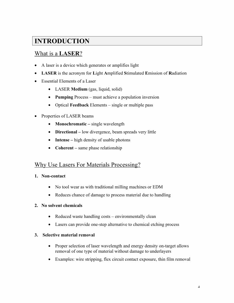
Photon Interactions with Matter
Possible photon interactions with matter include the following:
• transmission – Some photons go through some materials, perhaps associated with decrease in energy or change of direction
• absorption – the photon is absorbed by an atom or molecule
• scattering – the photon is scattered either elastically or inelastically
• spontaneous emission – the atom or molecule spontaneously drops to a lower energy state, giving off a photon
• stimulated emission – the photon stimulates the atom, causing it to emit an additional photon with identical characteristics to the stimulating photon
Figure 4 diagrams photon absorption and emission.
9

10
Reaction cross-section is a measure of probability that a reaction will take place, assuming the basic constituents needed for the reaction are present. Therefore, stimulated emission cross-section σstim emission is the probability that stimulated emission will occur between an excited atom or molecule and an incident photon.
Population Inversion
A laser requires a “population inversion” to sustain an output. A population inversion exists between two lasing energy states when there are more species (N) occupying the upper state than the lower. The process used to excite lower energy atoms or molecules to their excited states is called “pumping”.
Requirements for a population inversion in a 4-level system:
• Efficient pump mechanism and energy transfer to populate energy state E3
• Short lifetime τ3 for state E3
• Short lifetime τ1 for state E1
• High probability of stimulated emission in the laser medium, i.e. high stimulated emission cross section σstim emission
A population inversion exists when N2>N1 in Figure 5. Consequently, the laser pumping mechanism must be sufficient to replace those excited atoms or molecules undergoing spontaneous emission from E2, and those encountering photon absorption from state E1 to E2. Furthermore, if non-radiative decay lifetimes τ1 or τ2 are too long, an insufficient population in the upper energy state will result and will not support a laser pulse.

11
Essential Elements of a LASER Oscillator
A laser requires a lasing medium, pump process and a resonator cavity to sustain oscillation (Figure 6). The lasing medium can be a gas, solid, liquid, or semiconductor. The pump process excites the atoms or molecules of the lasing medium to an upper energy state by electronic means or kinetic energy transfer. Laser transmission is initiated by spontaneous emission and amplified by stimulated emission along the axis of the resonator cavity. The cavity mirrors reflect the photons back and forth through the laser medium for increased amplification.
Characteristics of the laser cavity:
• Rear resonator mirror is fully reflective
• Front optic is partially reflective and partially transmissive – for a helium-neon laser, the front optic is about 98.5% reflective, for an excimer laser, the front optic is only 10% reflective because of the high gain in the laser medium
• Resonator optics can be concave, as in a helium-neon laser, or flat, as in an excimer laser
• Lasing medium must have high stimulated emission cross section so more photons are produced than absorbed
• Methods of laser pumping: gas discharge, optical (flashlamp), chemical pump, laser pump, electron beam excitation, diode laser pump
Energy is introduced into the laser through the pumping process, but only a fraction of the “wall plug” energy is present in the laser beam as it exits the front aperture. A typical laser might be less than 10% efficient. Most of the energy is lost in the form of heat.

12
Types of Industrial Lasers and Their Categorization
Lasers are categorized according to lasing medium. The four basic types of laser media are gas, solid state, semiconductor and liquid dye. Emission frequencies of industrial lasers vary from the IR into the UV (Figure 7). Only gas and solid state lasers are practical for most industrial machining applications, although new solid state devices show great promise. Dye lasers are generally not used in industrial settings primarily because of the highly carcinogenic nature of the dyes and solvents.

13

14
Type Medium Wavelength
Gas Lasers Excimer 193-351 nm
Gas Lasers CO2 10 µm
Solid State Lasers Nd:YAG (Fundamental) 1.064 µm
Nd:YLF 1.047 µm
Nd:YAG (2nd harmonic) 532 nm
Nd:YAG (3rd harmonic) 355 nm
Nd:YAG (4th harmonic) 266 nm
Table 3. Common lasers used in industry.
CO2 Lasers
Characteristics of Carbon Dioxide Lasers
• most common laser in industry
• inexpensive
• wide range of power output capabilities
• high efficiency
• emission frequency of 9.4 - 11.0 um (infrared)
• high penetration depth (5 – 25 um or more)
• machining is a thermal process – material/photon interaction is primarily via vibrational excitation
• usually used in focal point machining mode except for CO2-TEA lasers
CO2 Laser Operational Theory
A carbon dioxide laser uses a gas mixture of CO2:N2:He. The CO2 molecules constitute the active lasing medium, the N2 gas serves in an energy transfer mechanism and the He atoms enhance the population inversion by depopulating the lower energy states. The population inversion and lasing transition in a CO2 laser is established between

15
vibrational and rotational energy states. Most CO2 lasers are pumped by a high pressure electrical discharge (Figure 8).
Gas Discharge Circuit Operation
1. Storage capacitor is initially charged when switch is open
2. When switch is closed, the capacitor discharges through anode and cathode
3. Surrounding atoms in laser gas become excited due to current flow across electrodes
4. Capacitor C becomes drained of its initial charge as lasing transition in the gas occurs
5. Ballast resistor R used to stabilize voltage across electrodes
6. Switch opens, thereby initiating recharge of capacitor C

16
Molecular Degrees of Freedom – Energy Storage
Energy is stored in molecules according to their electronic configuration and degrees of freedom associated with their physical construction. Listed below are the degrees of freedom associated with simple molecules in order of increasing energy storage.
• translational motion – 3 degrees
• rotational motion – 3 degrees for all molecules except linear molecules (2 for linear molecules)
• vibrational motion – 3N – 6 degrees (3N - 5 for linear molecules), where N = # atoms in molecule
• outer electron excitation ~ 5 eV
• inner electron excitation ~ 5 keV
• nuclear excitation ~1 MeV
CO2 is a linear molecule.
Energy Transfer
Excited CO2(00l) molecules are formed by three methods (Figure 9):
• Inelastic collision between electrons and ground state CO2 molecules
e- + CO2(000) → Co2(001)
• Vibrational-vibrational excitation via N2 molecules (laser gas mixture of CO2:N2:He)
1. Electrons in the gas discharge current excite N2 molecules vibrationally by inelastic collision
e- + N2(ν=0) → N2(ν=n), n = 1 to 8
2. Excited N2* molecules transfer energy to CO2 molecules
N2*(ν=n) + CO2(000) → N2 + CO2(001)
• Electronic excitation and ionization – minor contributor
• Theory and experiment show that 60% of wall plug power can be channeled into pumping the upper CO2 laser level, resulting in up to 27% wall plug efficiency. Intervibrational energy transfers from N2 account for this efficiency.

17
Types of CO2 Lasers
Type Beam Delivery Method Applications
CW Lower order mode Gaussian Focal spot High speed profile cutting; seam welding; cladding; engraving
Gate pulsed Lower order mode Gaussian Focal spot Cutting and drilling in metals; spot welding
Enhanced pulsed Lower order mode Gaussian Focal spot Cutting and drilling in IR reflective materials
TEA High order multi-mode Near-field imaging Marking in thermally insensitive materials; wire stripping; flex circuits; via drilling
Table 4. Types of CO2 lasers.

18
Important CO2 Machining Characteristics
• Material interaction via thermal overload and vaporization
• Penetration depth is 5 to 10 µm
• Ultimate feature resolution ~ 10 µm
• Practical feature resolution ~ 50 µm
• Inert gas used to limit oxidation in process area
Solid State Nd3+ Lasers
Solid state lasers are constructed by doping a rare earth element or metallic element into a variety of host materials. The most common host materials are Y3A15O12 (YAG), LiYF4 (YLF) and amorphous glass. The Nd:YAG laser is discussed because it is the most common solid state laser in industry.
Characteristics of Nd Lasers
• Typical solid state lasers are pumped optically by arc lamps or flashlamps (Figure 10). Arc lamps typically are used for continuous wave (cw) pumping; flashlamps are used with pulsed lasers. Diode laser pumping is becoming increasingly popular and will open doors to new industrial applications.
• Solid state lasers are electronically excited. The atoms of the active medium become excited when an electron jumps to a different orbit around the nucleus. In Nd:YAG and Nd:YLF lasers, the neodymium ions (3+) constitute the active medium.
• Nd lasers are easy to pump. All Nd lasers (Nd:YAG, Nd:YLF, Nd:glass) are four-level laser systems with numerous absorption bands above the upper lasing energy state 4F3/2. Atoms at these states readily decay to 4F3/2 making it easy to establish the required population inversion (Figure 11).
• Emission wavelength of Nd doped lasers varies somewhat with different host materials. Some host materials have a less defined lattice structure than others. The energy linewidths in these materials are “broadened” such that the transition wavelengths are different.
• Nd laser outputs can be frequency doubled, tripled or quadrupled through harmonic generation
• Nd lasers respond well to Q-switching

19

20

21
Characteristics of YAG Lasers
Type Beam Delivery Method Applications
CW Lower order mode Gaussian Focal spot Profile cutting; seam welding; cladding; engraving
CW pumped; Q switched
Lower order mode Gaussian Focal spot Cutting and drilling in metals; spot welding
Flashlamp pumped, pulsed
Lower order mode Gaussian Focal spot Cutting and drilling in metals; spot welding
Table 5. Characteristics and applications of YAG lasers.
Q Switching
Photons that evolve from spontaneous emission in directions other than along the laser axis are amplified like those along the axis. These photons, however, are not reflected back into the cavity and are lost in the environment. The combined loss of photons travelling off-axis is called amplified spontaneous emission (ASE).
A pulse energy enhancement technique called “Q switching” is used in many solid state lasers to minimize the negative effects of ASE. There are several switching devices in use, both optical and electrical. One such Q switch device is an electronic shutter, sometimes called a Pockels cell, that is triggered open and shut by an electrical signal (Figures 12 and 13).
Q-switch technique, step by step:
1. Laser is pumped with Pockels cell shut, cavity loss is high because the shutter prevents oscillation
2. Population inversion (gain) grows because pumping continues but there are few photons to invoke stimulated emission
3. Pockels cell opens
4. Cavity loss is greatly reduced now that oscillation is permitted
5. Optical output is produced causing population inversion to diminish and gain to reduce
6. Sequence is repeated for each laser pulse

22

23
Nd:YLF vs. Nd:YAG
• Not all Nd3+ lasers have identical characteristics
• For instance, the Nd:YAG fundamental wavelength is 1.064 µm, the Nd:YLF fundamental wavelength is 1.047 µm
• Nd:YLF pulse energy is greater than that for a similarly constructed Nd:YAG laser at low pulse rates as more energy can be stored per Q-switched pulse because the Nd:YLF upper state energy level lifetime, τYLF, is about three times longer than τYAG.
• The YAG host material has better thermal conductivity and more stable refractive index than YLF. The resulting parabolic temperature profile within the YLF laser rod produces a thermal lensing phenomenon that focuses the beam just outside the laser rod.
• Other solid state lasers are currently being investigated (Ruby, Alexandrite, etc.) for materials processing applications
Harmonic Generation
As a result of the proliferation of laser experimentation in the 1960’s, it was discovered that some materials exhibit a nonlinear optical effect when irradiated with high energy laser emissions. More specifically, the electric dipoles established by the electrons and the nuclei in these materials oscillate in response to incident radiation such that two separate wavelengths of light exit the material. The output of these emissions include the original wavelength and a component half the wavelength of the incident beam. This phenomenon is called harmonic generation. Other techniques also allow sum and difference frequency light generation (Figure 14).
24
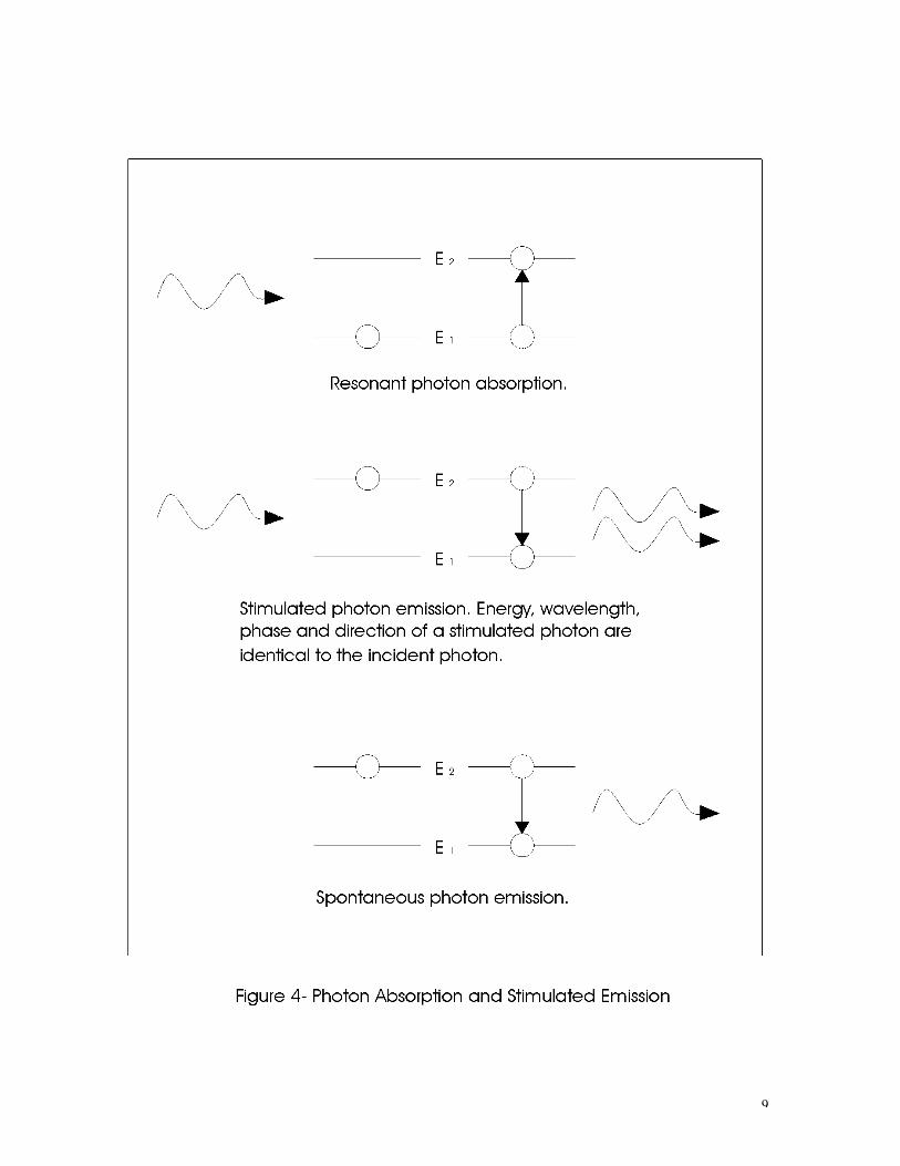
Harmonic generation is useful in creating different wavelengths, however, total output energy of the shorter wavelength component is typically reduced to one-half the energy of the incident radiation or less.
Fundamental Doubled Tripled Quadrupled
YAG 1064 nm 532 nm 355 nm 266 nm
YLF 1047 nm 524 nm 349 nm 262 nm Table 6. Harmonic frequencies of Nd:YAG and Nd:YLF lasers.
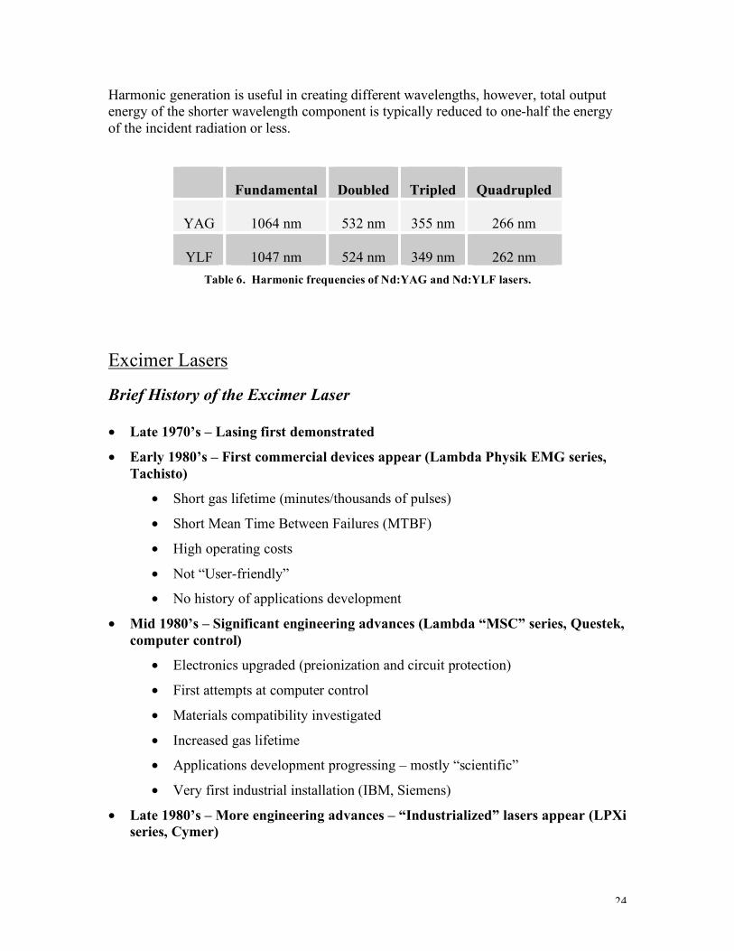
Excimer Lasers
Brief History of the Excimer Laser
• Late 1970’s – Lasing first demonstrated
• Early 1980’s – First commercial devices appear (Lambda Physik EMG series, Tachisto)
• Short gas lifetime (minutes/thousands of pulses)
• Short Mean Time Between Failures (MTBF)
• High operating costs
• Not “User-friendly”
• No history of applications development
• Mid 1980’s – Significant engineering advances (Lambda “MSC” series, Questek, computer control)
• Electronics upgraded (preionization and circuit protection)
• First attempts at computer control
• Materials compatibility investigated
• Increased gas lifetime
• Applications development progressing – mostly “scientific”
• Very first industrial installation (IBM, Siemens)
• Late 1980’s – More engineering advances – “Industrialized” lasers appear (LPXi series, Cymer)
25
• Lasers fully computer controlled
• Longer gas lifetime (days/millions of shots)
• Increased industrial applications development due to improved lasers, miniaturization trends, unique capabilities
• Increasing installed industrial base
• 1990’s – Materials compatibility issues drive costs down, gas lifetimes up (weeks/tens of millions of shots per fill)
• Large installed industrial base (Lambda 1000, 2000, 3000 series, Cymer lithographic lasers, Lumonics Index and PM848)
• Continued applications development in many new, unique and exciting fields
• Excimer lasers become increasingly visible in industrial settings: 24 hours/day, 7 days/week operation
• Excimer lasers become known as the “third” industrial laser alongside CO2 and solid state lasers
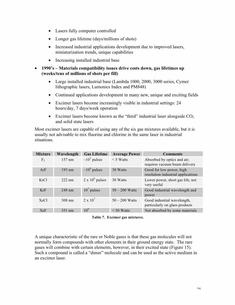
Most excimer lasers are capable of using any of the six gas mixtures available, but it is usually not advisable to mix fluorine and chlorine in the same laser in industrial situations.
Mixture Wavelength Gas Lifetime Average Power Comments
F2 157 nm ~105 pulses < 5 Watts Absorbed by optics and air; requires vacuum beam delivery
ArF 193 nm ~106 pulses 30 Watts Good for low power, high resolution industrial applications
KrCl 222 nm 2 x 10⁶ pulses 30 Watts Lower power, short gas life, not very useful
KrF 248 nm 107 pulses 50 – 200 Watts Good industrial wavelength and power
XeCl 308 nm 2 x 10⁷ 50 – 200 Watts Good industrial wavelength, particularly on glass products
XeF 351 nm 106 < 50 Watts Not absorbed by some materials
Table 7. Excimer gas mixtures.
A unique characteristic of the rare or Noble gases is that these gas molecules will not normally form compounds with other elements in their ground energy state. The rare gases will combine with certain elements, however, in their excited state (Figure 15). Such a compound is called a “dimer” molecule and can be used as the active medium in an excimer laser.

26

27
Excimer Laser Energy Transitions and Pump Scheme
The pump scheme for the KrF excimer laser shown in Figure 16 is electronic. The lower Kr + F state is unbound or repulsive; the Kr and F atoms cannot move close to each other because of the lower state energy barrier at the far left. When pumped by the gas discharge, the Kr and F atoms are ionized and form the excited dimer molecule at the upper energy state labeled Kr+ + F-. The atoms can approach closer, now that the previous energy barrier no longer exists. The lifetime for the KrF* molecule in this state is less than 5 ns during which stimulated emission must occur, or the atoms will fall to their ground state spontaneously or through collisions.

28
Important Properties of KrF and Other Excimer Lasers
• Since the lower state does not exist in the bound condition, it is easy to populate the upper, bound state. This condition and the high stimulated emission cross-section for KrF make a population inversion easy to establish and the laser medium gain very high.
• The frequency of the excimer UV transmission is sufficiently energetic to break the chemical bonds of most materials. For many materials machining is accomplished through ablation instead of thermal overload.
• The pumping mechanism for excimer lasers is a gas discharge with up to 45 kV peak excitation voltage. High voltages and currents of this magnitude test the limits of electronic technology. High voltage power supply failures in excimer lasers are an issue to address in proper laser design.
• The partial reflectance of the front resonator mirror is only 10% because of the high gain.
A typical excimer laser gas mixture is a Kr:F2:Ne blend with neon constituting most of the volume. The neon acts as a third body collision partner in the formation of the excited KrF* molecule (Figure 17). The voltages and currents required for excimer laser operation test the limits of high voltage electronic technology. Consequently, excimer lasers are more complex than other types of lasers, require more maintenance and are more expensive to maintain.
The laser medium in an excimer laser is pumped by a high speed transverse electrical discharge. DC high voltage is supplied to the pulse forming network that consists of a thyratron switch, magnetic pulse compression circuit and storage capacitors. When the thyratron switch is closed, a high voltage spike is impressed across the preionization pins and electrodes, ionizing the gas and pumping the excimer atoms to their excited state.

29

30
Gas Discharge
The actual gas discharge excitation process takes place in four steps: preionization, kinetic transfer, formation of excited dimers and laser transition.
An initial electron density of 107 – 108 electrons/cm3 is required to produce a sufficient population inversion between the upper and lower energy states. Typical industrial excimer lasers employ spark preionization to achieve this. The preionization pins are timed to fire just prior to when full high voltage reaches the electrodes, thereby providing the electron density required.
Step 1: The thyratron actuates and places 45 kv across preionization pins and electrodes, creating a gas plasma.
Step 2: The electrons in the gas plasma are accelerated by the electric field between the electrodes as they transfer their kinetic energy to the surrounding atoms.
Step 3: Excited KrF* molecules are created by inelastic collision with the electrons. These molecules have an approximate lifetime of >5 ns in their excited state and will decay spontaneously if not stimulated by an additional photon.
Step 4: The laser transition step is initiated by those photons produced by stimulated emission along the laser axis. These photons are reflected back along the axis by the resonator optics at each end of the laser so that they may subsequently produce stimulated emission with other excited molecules. The laser emission occurs in about a 20 ns pulse because the electronic circuitry can not sustain a constant high voltage and the gas discharge is short-lived.
After the pulse is completed, the gas constituents require a 100 ms relaxation period before they can participate in the next discharge cycle.
The relaxation time requirement of the excimer gas mixture places a significant constraint on the pulse rate capability of the laser. The laser is limited to a pulse rate compatible with the 100 ms relaxation time unless the gas between the electrodes is replenished. A typical excimer laser overcomes this constraint by recirculating the laser gas so the volume of the gas is completely refreshed and exchanged several times between laser pulses. At the same time, the gas is cooled and filtered during the circulation process such that repetition rates of 400 pulses per second or higher are achievable.

31
Major Components of an Excimer Laser
List of components:
Laser head Energy monitor Electrodes, preionization pins, rails Beam sampling optics Electrostatic particle precipitators Photodiode detector Cooling fins A/D circuitry Blower assembly Pulse forming network Gas handling system Thyratron switch Gas manifold Magnetic pulse compression Solenoid valves Storage capacitors Interlock control HV power supply Computer control system Switched mode type Automated energy stabilization Delivers stabilized DC high voltage Noise immune communications with At 15-25 kV other subsystems (fiber optics) Automated gas adjustments and refills

32
Excimer Laser Energy Monitoring
During normal operation, laser output energy depends on the high voltage setpoint. Raising the high voltage setpoint increases the energy of the laser beam. Therefore, the output energy of the excimer laser must be monitored to ensure uniform machining. The energy monitor mounted at the front aperture provides pulse energy information to the laser control computer. If the energy varies, the computer increases or decreases the high voltage setpoint to compensate.
As the laser gas ages, high voltage excitation must be increased periodically to maintain laser energy at a constant level. This voltage adjustment can be accomplished by computer or manually. Eventually, the high voltage power supply limit will be reached and separate measures must be undertaken. Three adjustments to the gas mixture are possible:
1. Halogen injection – a spurt of fluorine gas injected into the laser reservoir can extend gas lifetime significantly. This method can be repeated several times until further injections are ineffective.
2. Partial gas replenishment – a significant portion of the laser gas is removed and replaced with fresh volume in the correct component gas ratios. At some point, even this method becomes ineffective.
3. New fill – the entire reservoir is evacuated and replaced with fresh gas. A new fill is necessary when other methods fail.
Beam profile
After a new gas fill, the excimer laser beam profile is Gaussian on the short axis and flat-topped along the long axis (Figure 19).
As the gas fill ages, changes in chemistry alter the electrical properties of the gas. These changes result in beam growth along the short axis. The beam changes to a flat-topped profile on both axes, beam divergence increases and peak pulse energy is reduced in the far field. A halogen injection or partial gas replenishment will counteract these changes temporarily, but full beam profile will not be restored completely without a new gas fill.
Sputtering electrode and preionization pin material over the life of the laser generates minute particles of dust within the resonator cavity. The dust plates out on the resonator window as well as on other internal components. Dust on the windows absorb UV emission, particularly in the central portion of the optics, and damages the optic over a period of time. Therefore, regular window cleaning is critical to proper laser operation.
Resonator optics must be aligned perpendicular to the beam axis for efficient laser oscillation. Misalignment of the windows causes the optical feedback to be skewed with

33
respect to the gain medium, resulting in lower overall gain. Misalignment in the long axis results in hot spots in the beam profile; misalignment along the short axis causes a dramatic drop in total power, often without discernible hot spots.
As the preionization pins wear, the spark gap increases, adversely affecting gas preionization. As the cathode wears and becomes more flat, the discharge becomes non-uniform. Worn electrodes or preionization pins can cause a trapezoidal or split beam, as shown in Figure 19e. This effect cannot be corrected by resonator alignment and becomes more pronounced as the gas fill ages. The resulting non-uniform power density of the beam is unacceptable for critical applications. Laser refurbishment is the only remedy.

34
Beam Profilometry
A typical beam profilometer employs a photoluminescent crystal as the detector (Figure 20). A small fraction of the laser beam is deflected into the crystal for measurement by a beam splitter. The intensity of fluorescent emissions by the crystal is proportional to the intensity of the incident UV light. Hence, a visible image is created analog as to the spatial intensity profile of the beam. This image is relayed to a CCD camera where it is digitized, processed and analyzed by a video image processor. The processed image consists of a false color intensity map or 3-D histogram.

35
Beam profilometry has the following applications:
• Real-time viewing of the laser output while the system is enclosed
• Diagnosis of laser or resonator optics problems
• Helpful during resonator optics alignment after maintenance
• Long term laser performance monitoring
• Process monitoring for applications sensitive to beam profile (on target or mask plane diagnostics)
Two types of beam profile viewing are possible:
1. Raw beam viewing directly from the laser
• Good for diagnosing laser problems
• Assists during laser alignment
2. Mask viewing
• Permits on-target energy distribution analysis
• Provides process control information
• Verifies proper alignment of mask
Types of Excimer Lasers
Some well-known manufacturers of industrial excimer lasers are Lambda Physik (Goettingen, Germany) and Lumonics, Inc. (Kanata, Canada). Performance characteristics for several excimer lasers manufactured by these companies are provided below.
Parameter (KrF) Lambda 1000
LPX220i Lumonics PM-848
Lumonics Index 886
Max pulse energy 300 mJ 450 mJ 450 mJ 600 mJ Max average power output 60 W 80 W 80 W 30 W Beam size 8 x 24 mm 8 x 23 mm 10 x 25 mm 14 x 30 mm Beam divergence (mrad) 4.5 x 1.5 1 x 3 1 x 3 1 x 3 Pulse repetition rate (pulses/sec) 0-200 0-200 0-200 0-50
Table 8. Laser parameters for several industrial excimer lasers.
Unique Characteristics of Excimer Lasers
• Resonator cavity configuration produces a beam ideal for near-field imaging
36
• High peak power of the laser beam permits ablation of the target material with little or no heat affected zone
• The 193-351 nm optical wavelength permits generation of high resolution (~1 µm) features on the target surface
• The shallow absorption depth permits tight control of feature depth by controlling the number of pulses applied
• Large beam cross-section accommodates a large imaging mask for near-field imaging
Disadvantages of Excimer Lasers
• High performance electronic components require frequent and costly maintenance
• Laser gas is toxic and corrosive
• Laser gas consumption is high and expensive
• Changes in gas chemistry affect beam shape and quality
• Components inside laser require routine replacement and cleaning due to corrosiveness of the laser gas
• Resonator optics and beam delivery optics degrade with the exposure to UV light and require replacement
• Optics need routine cleaning
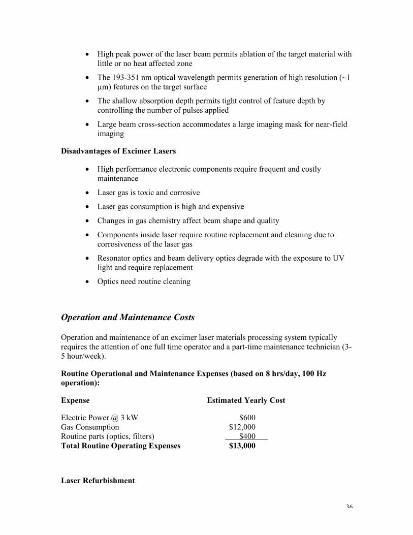
Operation and Maintenance Costs
Operation and maintenance of an excimer laser materials processing system typically requires the attention of one full time operator and a part-time maintenance technician (3-5 hour/week).
Routine Operational and Maintenance Expenses (based on 8 hrs/day, 100 Hz operation):
Expense Estimated Yearly Cost
Electric Power @ 3 kW $600 Gas Consumption $12,000 Routine parts (optics, filters) $400 Total Routine Operating Expenses $13,000
Laser Refurbishment

37
Excimer lasers are designed to operate over a range of different pulse rates. Lasers at high pulse rates typically have lower output power. Therefore, a laser runing at 200 pulses per second would still require refurbishment after one billion pulses, which would occur after six months. Laser Refurb (every 1 billion pulses or approximately every year at 100 Hz) $17,000 Total Laser Operation And Maintenance $30,000
Laser refurb is required approximately every year for a laser operating 8 hours/day. A refurb normally includes the following:
• Clean and acid etch all internal surfaces of laser • Electrode replacement • Complete preionization pin replacement • Fan assembly and precipitator replacement
The refurb does not include the replacement cost of the thyratron, heat exchangers, capacitors, halogen filter or resonator optics. If these items require replacement, additional charges are levied.
Principles of Laser Materials Processing
Review of Optical Physics
The part of a laser processing system that directs the beam to the target, once the beam leaves the laser head, is the beam delivery system. Components of the beam delivery system include the masks, turning mirrors, attenuators, field lenses and imaging lenses that manipulate and shape the beam, and the optical chamber that holds these devices.
The Law of Refraction (Snell’s law) (See Figure 21)

38
1. The incident, reflected and refracted rays, and the normal to the surface, lie in the same plane.
2. The angle of reflection is equal to the angle of incidence.
3. For a light ray traveling through two media 1 and 2, the ratio
constantsin
sin
2
1=
!
!
If material 1 is a vacuum, then the constant is specific to material 2 and is called the index of refraction. The index of refraction of a material is an indicator of the speed of light traveling in the medium (Figure 22).
A more familiar way of writing Snell’s law for two materials is:
n1 sinθ1 = n2 sinθ2.

39
Optical Components Optical components in the beam delivery system shape and guide the laser beam to the target surface. The optical properties of these components vary significantly and so do the prices. Ultraviolet optical materials:
• Magnesium fluoride (MgF2) – best resistance to radiation damage but most expensive
• Fused silica (SiO2) – medium cost; reduced transmission at shorter wavelengths
• Calcium Fluoride (CaF2) – degrades slowly with exposure to electromagnetic radiation; least expensive
Infrared optical materials:
• Germanium (Ge) – high refractive index n = 4.0; exhibits poor transmission qualities at high temperatures > 200ºC
• Zinc Selenide (ZnSe) – refractive index n = 2.4; scratches easily; requires AR coating
• Sodium Chloride (NaCl) – low refractive index; water soluble, good transmission
Nd:YAG optical components are usually fused silica.
The price of optical components depends on the substrate material, coating, diameter and focal length, if applicable. The table below lists some typical prices for UV optics.
Plano-Convex Lens CaF2 Fused Silica MgF2 1.5-inch, 75mm $325.00 $400.00 $500.00 1.5-inch, 100 mm $200.00 $200.00 $325.00 1.5 inch, 200mm $140.00 $180.00 $250.00
Table 9. Estimated relative prices for UV lenses. In general, the shorter the focal length, the more expensive the lens.
Considerations in choosing optics:
• Proper wavelength
• Compatibility with the surrounding environment, i.e. moisture, temperature
• Resistance to irradiation
• Beam size

40
• Demagnification and fluence requirements
• Cost
Many optics, mostly those with high index of refraction, come with an anti-reflection (AR) or interference filter coating. Coated optics cost more but may improve machining quality, depending on the application. Consistency of the coatings depends on the manufacturer. (Figure 23)
The high divergence of excimer lasers leads to unacceptable optical losses where long beam delivery systems are used. The employment of unstable resonator optics can remedy this problem in some instances. An excimer laser with unstable optics is difficult to align and emits a reduced energy output. A stable, flat/flat resonator cavity like that shown in Figure 24(a) delivers a low divergence of about 1 x 3 mrad. Resonator optics in this configuration as in an excimer laser, cost nearly $900.00 a set. The unstable resonator cavity shown in Figure 24(b) produces a divergence near 0.1 x 0.3 mrad but at only one-half the output as in 24(a). Typical price for unstable resonator optics is $3,000.00 per set.

41
Figure 25 shows some important relationships for a thin lens. Figure 26 shows other simple optical parameters.

42
Beam Splitters
Two main methods are used to split an incident beam into two or more components. The first is by using a dielectric coated optic. Depending on the coating, a portion of the beam will be transmitted and a portion will be reflective. In many cases, a beam will be split in equal halves using a 50%, 45º to incidence beam splitter. This transfers the original beam size to both resulting beamlets, but reduces energy density and peak power by half, so in many cases the technique is not useful – especially when the beam is to be split into many components (Fig. 27).

43
Frequently a better way to split the beam is by using a physical divider and “scraping” off portions of the beam (Fig. 28). We have successfully employed this technique to split an incident excimer laser beam into 12 equal components.
Telescopes
Normally, laser beams have very small beam diameters. If larger objects are to be illuminated, or if one wishes to fill an imaging lens to get the smallest spot size, the system must be expanded. Expansion can be achieved two ways (Figure 29) as illustrated by the following:

44
The first method uses two positive imaging lenses of the Kepler telescope type (Figure 30). It offers the advantage of having a real focus at which a spatial filter can be easily inserted. The disadvantage, however, is that for powerful lasers, the extremely high beam intensity at the focus can cause breakdowns in air.

45
The second method uses a negative entrance lens and a positive collimator lens of the reversed Galilean type (Figure 31). It offers the advantage of being shorter than the Kepler type and has a virtual focus which prevents air breakdown. On the other hand, a spatial filter cannot be inserted.
The expansion ratio in each case is characterized by the focal length ratio and the divergence of the laser beam is reduced by the absolute value of the ratio of the two focal lengths.
If we wish to reduce the beam diameter by reversing the lens arrangement, the divergence will increase by the absolute value of the focal length ratio. i.e. we can no longer expect “parallel” laser light. Nonetheless, this technique can be used to get higher throughput for a simple mask or to achieve a higher energy density in a “collimated” beam.
Homogenizers
The purpose of a beam homogenizer is to break up the beam into small sections and recombine them in a pattern that increases the overall fluence over a smaller cross-section. The following considerations must be taken into account:
1. Loss of power density in one part of the raw beam must not affect uniformity of the beam at the mask exposure plane
2. Significant optical losses are present in any homogenizer configuration
3. Homogenizers are expensive and AR coated – the coatings are susceptible to overheating by hotspots within the raw beam
Figures 32, 33 and 34 show three different types of homogenizers used with excimer lasers.

46
47
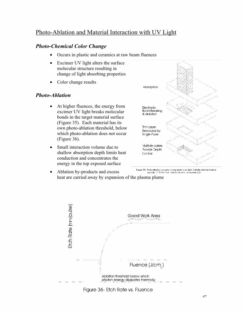
Photo-Ablation and Material Interaction with UV Light
Photo-Chemical Color Change • Occurs in plastic and ceramics at raw beam fluences
• Excimer UV light alters the surface molecular structure resulting in change of light absorbing properties
• Color change results
Photo-Ablation
• At higher fluences, the energy from excimer UV light breaks molecular bonds in the target material surface (Figure 35). Each material has its own photo-ablation threshold, below which photo-ablation does not occur (Figure 36).
• Small interaction volume due to shallow absorption depth limits heat conduction and concentrates the energy in the top exposed surface
• Ablation by-products and excess heat are carried away by expansion of the plasma plume

48
Thermal effects • As fluence increases, absorption depth increases resulting in larger interaction
volume; greater volume results in increased heat conduction to the surrounding material
• As pulse repetition rate increases, residual heat cannot escape, resulting in thermal effects
• Laser light absorbed by materials below ablation threshold can impart significant heat to the material
• Certain materials such as metals are removed by thermal input at high fluences; however, small interaction volume helps control thermal damage
Taper Effects
Although the shape of the image at the target surface resembles the true shape of the mask, during near field imaging, the perimeter of the image tends to collapse inward as the photo-ablation depth penetrates into the material (Figure 37).
Characteristics of taper:
• Taper angle is approximately 7º - 10º as the cutting depth penetrates into the processed material. This can be increased by using low fluence or other beam motion techniques. It can be reduced to approximately 2º in low aspect ratio applications by the use of high fluence and low divergence resonator optics. It is also possible to use double sided drilling (simultaneous or serial processing) to reduce taper. This sometimes leaves an “hourglass” shaped feature.
• The consequence of the taper phenomenon is that the exit hole on one side of the processed part will be smaller than the entrance hole – the size difference depends on the thickness of the material
• Taper effects must be considered when choosing mask sizes and demagnification parameters

49
Ablation Parameters
Achievable Exposure Area: Excimer Raw Beam Energy vs. Fluence Raw Beam Energy 0.5 J/cm2 1 J/cm2 5 J/cm2 10 J/cm2 25 J/cm2 100 mJ 0.2 cm2 0.1 cm2 0.02 cm2 0.01 cm2 0.004 cm2
200 mJ 0.4 cm2 0.2 cm2 0.04 cm2 0.02 cm2 0.008 cm2
400 mJ 0.8 cm2 0.4 cm2 0.08 cm2 0.04 cm2 0.016 cm2
600 mJ 1.2 cm2 0.6 cm2 0.12 cm2 0.06 cm2 0.024 cm2
Table 10. This table displays the maximum surface area a raw beam energy can deliver at the fluence levels listed across the top. The data is based on a 2 cm2 raw beam size.
For any fluence ρ and area a, the product ρ x a will be a constant; that is:
ρLaL = ρTaT.
For example, the area illuminated by a 100 mJ beam and fluence 5 J/cm2 can be calculated:
202.0 cm
T
===5 . 0
(0 .1/2)(2)aa LLT
!
!
Process Material Type
Laser Wavelength
(nm)
Fluence (J.cm2)
Power Density
(MW/cm2)
Etch Depth/Pulse
(microns)
Comments
Etching Plastics 193 248 308
0.5 to 2 50 to 200 0.1 to 1 Imaging patterns, arrays
Etching Ceramics and hard dielectrics
193 248 308
5 to 15 500 to 1500 0.1 to 0.3 Imaging patterns, arrays
Etching Metal foils 193 248 308 351
5 to >20 500 to >2000
0.1 to >0.25 Imaging patterns, arrays
Drilling Plastics > 1mm
193 248 308
3 to 10 300 to 5000 0.2 to 5 Spot imaging
Drilling Ceramics and hard dielectrics
193 248 308
10 to >50 2000 to >5000
0.2 to 2 Spot imaging
Drilling Metals 193 248 308 351
20 to >50 2000 to >5000
0.2 to 2 Imaging patterns, arrays
Marking Plastics 308 351
0.5 to 2 50 to 200 0.1 to 1 Imaging patterns, arrays
Marking Ceramics and hard dielectrics
308 351
1 to 15 100 to 500 0.1 to 0.3
Table 11. Processing parameters for different excimer wavelengths and materials.

50
Beam Imaging and Focusing
Two methods of laser machining are used in industry. Focal point machining typically is used with solid state lasers and CO2 lasers that do not have longitudinal electrodes. Near-field imaging is possible with excimer lasers and TEA CO2 lasers because the multimode emissions offer a uniform cross-sectional energy density.
Characteristics of Near-field Imaging
• Fluence and spatial distribution controlled by optical magnification
• Image quality is independent of beam divergence, diffraction, and incoherence
• Fairly simple optical setup
• High tolerances achievable – imperfections in mask demagnified
• Theoretically, imaging resolution is on the order of emission wavelength
• Excimer laser 0.2 – 0.4 µm
• Nd:YAG laser (Fundamental) 2 µm
• CO2 laser 20 µm
• In reality, practical imaging resolution is dependent on optics:
• Excimer laser 1-5 µm
• Nd:YAG laser (Fundamental) 5 µm
• CO2 laser 75 µm
Advantages of Near-Field Imaging Disadvantages of Near-Field Imaging Very flexible for a wide range of shapes Mask must fit into usable portion of the beam Fairly simple optical setup Focus is critical to feature quality High tolerances can be met Spherical aberration can distort image shape Choice of different masks for different applications (metal, chrome on quartz, dielectric)
Energy density non-uniformity across the mask is duplicated on the part
Very wide range of demagnification possible Work area on process material limited by demagnification
Table 12. Advantages and disadvantages of near-field imaging.
Near-field imaging involves use of a mask to project a pattern of light onto a part. The features of the mask are etched into the target material at a magnification determined by the relative positioning of the optical elements.

51

52
Thin Lens Equation and Demagnification
The relationship between the mask, imaging lens and image on the target material is described by the thin lens equation:
fIO
111=+
O = object distance I = image distance f = focal length (normally expressed in millimeters)
(See Figure 38)
The term magnification in optics is normally used to describe the ratio of the image size to the size of the object. Magnification implies that the image size is greater than the size of the object. The term demagnification implies that the image is smaller than the object and is described by the equation:
,I
Od =
where d is the demagnification.
Beam Compression
Fluence
The term fluence describes the amount of energy per area deposited on the target surface by a single laser pulse. Fluence should not be confused with pulse energy, because the amount of fluence that strikes the target depends on transmission losses in beam delivery components as well as spatial compression of the beam. Fluence is important in laser machining because specific materials require minimum fluence levels to produce thermal ablation or photo-ablation in the case of excimer lasers. This is shown by the following equation:
,A
E=!
where ρ is the fluence (J/cm2), E is the energy measure on-target in Joules, and A is the area of the image. Fluence can be determined for focal point applications as well, where A is the area cross-section of the beam at the focal point.
Cylindrical Compression
A cylindrical lens is normally used for scanning a large area with a relative low fluence and for planarization. If a cylindrical optic is used to compress the beam, then the
53
dimension of the beam changes only in one direction. The fluence after compression, ρ1, is given by:
ρ1 = ρ0d(1-Lf),
where ρ0 is the initial fluence before the lens, and d is the demagnification factor, and Lf is the percent loss through the optic. Optical losses typically run about 5% per optical element, so it is important to minimize the number of optical elements in the design of the optical system.
Spherical Compression
If a spherical optic is used to compress the beam, then the dimension of the beam changes in both directions. The fluence after compression ρ1 in this case, is given by:
ρ1 = ρ0d2(1-Lf),
where ρ0 is the initial fluence, d is the demagnification factor, and Lf is the percent loss through the optic. Size constraints placed upon the optical systems limit the achievable demagnification factor and fluence for a given lens focal length. Substituting the demagnification equation into the thin lens equation to obtain:
O = (d + 1)f
.)1(f
d
dI
+=
Size and Energy Constraints in Near-Field Imaging
• The optical chamber can be insufficient in length to accommodate a specific demagnification for a given lens (either too long or too small).
• Laser energy can be insufficient to photo-ablate certain materials for a specific demagnification
• The vertical (short) beam width may be too small to accommodate a mask required for a specific demagnification or image size.
• The required image and mask size (<0.004 inch) can be small enough to create undesirable diffraction interference at the image plane. This condition is a particularly serious limitation if the image is a repeated pattern of holes or shapes.

54
Beam Utilization Factor (BUF)
Beam Optimizing Considerations
• Optimum beam utilization is essential to quality part manufacturing at affordable costs.
• Techniques for optimizing BUF include parallel processing schemes in which on laser beam illuminates multiple imaging systems to process many parts simultaneously.
• Size of usable fraction of the beam is highly dependent on resonator optical alignment.
• Definition of useable fraction of the beam is application dependent. One process may require tighter fluence control than another.
• Refractive optical materials absorb a small fraction of the beam. This absorption depends on optic thickness.
• Reflection from surfaces of refractive optics contributes to losses.
• Reflective optical components have losses of 1-2%.
• Absorption losses can be minimized by proper choice of optical materials and high quality optics workmanship.

55
• Reflective losses with refractive elements can be minimized with angle and wavelength dependent high-reflection dielectric coatings.
• Losses are best controlled by limiting the number of optical elements. Refractive optics should be as thin as possible.
• Sometimes more elements are acceptable if the process requires high precision and beam utilization is a secondary consideration.
Motion control of beam delivery components provides a powerful method of automating part processing with laser systems. The following list describes just a few of the motion control alternatives involving beam delivery optical setups:
Autofocus – the lens is focused automatically by a stepper motor controlled by the system computer at the touch of a key or through a process program.
Automagnification – the mask and lens are slewed according to algorithms derived from the thin lens equation.
Rotary or linear mask control – a rotary mask or linear mask assembly is actuated by a computer controlled stepper motor or pneumatic device. Mask alignment permits high precision overlays, such as counterbored holes. Mask aligners with letter stencils can produce custom serialization marks under computer control.
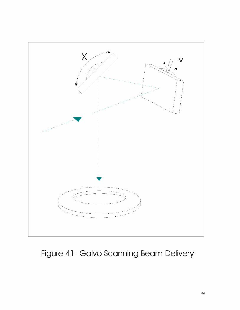
Galvanometer Beam Steering – in many applications, the processing time would be too slow if the beam remained still and the part moved, for instance using an X/Y table (Figure 40). A preferable method in many cases, especially for well collimated beams of low divergence, is to hold the part still and move the beam with mirrors mounted on opposing orthogonalized galvanometers (Figure 41). Areas up to 4” in diameter can be exposed on target at extremely high speeds, depending on the sensitivity of the application to angular distortions. Area galvo scanning can be combined with table stepping to provide a high speed method of processing larger parts.
56

57
Special Beam Delivery Techniques
Scanned Illumination Imaging
Scanned illumination imaging is a powerful technique for increasing the image surface area on the target material without the reduction of fluence (Figure 42). Using a properly designed lens system, 3 µm feature resolutions at 20 J/cm2 fluence with feature areas of 2 mm2 have been achieved. Important considerations when implementing this technique are:
1. Imaging lens must have sufficient aperture to accommodate the entire image
2. Laser pulsing must be interpolated accurately with the scanning mirror feedrate 3. Optical setup must be configured to accept the scanning mirror and fixed mask

58
Coordinated Opposing Motion Imaging
In coordinated opposing motion imaging (Figure 43), both the mask and part are mounted to computer controlled X-Y stages. During processing, the mask and stages perform interpolated moves in opposing directions, the magnitude of mask movement being larger by a factor equal to the image system demagnification. This opposing motion causes the laser image to precisely track the position of the moving part, remaining at the same position relative to the part as different areas of the mask are exposed. The lens is always used in the paraxial, on-axis condition.

59
Direct Write Machining
Direct write machining provides a useful technique of generating large cutout features and performing high volume hole drilling in materials where fluence requirements limit spot size. The required features can be drawn in CAD and then directly translated to motion control code utilizing a CAD/CAM programming interface (Figure 44). Specific functions possible using this technique include:
1. Features on the CAD drawing can exist on different layers that correspond to automatic mask changes or changes in laser pulse spacing within a single process program
2. Points can be placed in the CAD drawing to trigger step and repeat drilling operations
3. Drill marker points can be drawn on different layers within the CAD file to control drilling depth

60
Contact Mask Processing
Contact mask processing is a technique by which fluence on-target is controlled by simple beam shaping optics and feature shape is determined by a blocker mask in contact with the workpiece (Figure 45). The exposure of the contact mask may be performed with the part stationary or scanned under the beam. If scanning is used, laser firing must be interpolated with the table feedrate to ensure uniform exposure. Contact mask scanning allows very large areas of material to be processed. Characteristics and considerations in contact mask processing:
1. The blocker mask material must be selected so the beam does not damage the mask as it ablates the material below:
• Aluminum
• Copper
• Molybdenum
2. If the mask is not expendable, select the minimum fluence required to minimize the damage.
3. Periodic cleaning of the mask edges is required for maintaining sidewall quality.
• Feature resolution is limited by the limits of the size of the feature that can be put into the mask. Features down to 25 µm have been achieved.
• A conformal mask can be laminated to the workpiece as an integral component of the final product – good approach for via formation in microelectronics packaging.

61
Beam Dividing Beam dividing can be used to increase the BUF as illustrated in Figure 46. Figure 47 shows a technique used to split the beam from a CO2 laser into seven components and shutter each beamlet to produce continuous marks on a moving production line. Alternatively, many small lasers can be used and fired only on demand.

62
Steps to an Effective Optical Setup 1. Determine which laser is best.
• Are machining quality and tolerances tight enough to warrant UV laser use or can CO2 or Nd:YAG do the job?
• Is the target material thin enough for excimer laser machining, or is a CO2 wavelength required?
• What is the best wavelength, and should more than one laser be used?
• How much fluence is required?
2. If excimer laser imaging is chosen, determine the wavelength and energy required.
• Is 193 nm, 248 nm, or 308 nm best absorbed?
• What is the ablation threshold of the material?
• Experiment to determine optimum fluence and wavelength, if possible.
3. Determine required exposure area.
• What are the required feature sizes?
• Can feature be broken into smaller portions?
• How long will it take to accomplish the job?
4. Determine resolution and optical setup type.
• Contact mask or imaging system (LWD or microscope system?)
• Which objective is best?
• Select an objective that minimizes optical losses
5. Determine pulse energy required
• Required pulse energy on-target = required fluence x feature area
• Don’t forget to factor in optical losses
6. Determine optical parameters
• Select demagnification
• Maximize BUF, use beam shaping/splitting as required
• Determine optical path, use readily available optics
• Consider size of beam delivery system and support structure
• How critical is beam uniformity? Homogenizer? Consider losses
• Don’t forget to factor in taper effect

63
7. Select laser and illumination scheme
• Laser energy required = required pulse energy on target x BUF
• Select lowest pulse energy laser to do the job
• What if required pulse energy is greater than maximum output of available lasers?
• Reconsider optics scheme to reduce losses
• Consider scanned illumination technique

64
System Integration
Processing System Considerations
1. General Requirements
• Choose the correct laser
• On-line or off-line
• Clean room requirements?
• Available utilities – electrical, cooling, venting, gases
2. Beam Delivery System (BDS)
• Gets photons from laser to workpiece
• Shapes and conditions beam for efficiency (including automated BDS)
• Protects operators
3. Motion Control/Parts Handling
• X, Y, Z, θ stages
• Galvos?
• Robotic or conveyor required to move parts?
• Tooling or part pallets; roll-to-roll?
• Vacuum chucks, assist gas?
• Camera system? Simple or machine vision? Color or black & white?
• Computer control
• Safety – Class I operation – gases, optics, stray light, mechanical, electrical
Laser Packaging
• Industrial laser packages are available from many laser vendors
• System houses often repackage non-industrial packaged lasers into turnkey systems
• Industrial packaging must incorporate laser safety features as mandated by U.S. Federal law (beam stop)
• Maintenance access features:
• Quarter turn latches on exterior panels
• Quick-change resonator windows

65
• HeNe laser resonator optics alignment system
• Modular subassemblies
• Quick-change laser or laser vessel
Part Viewing Systems
Choice of an imaging system depends on the dimensions of required optical parameters and practicality. Two types of imaging systems are available:
1. Long working distance (LWD) setup
• Objective focal lengths greater than 50 mm
• Object distances up to 2 meters
• Working distances to 250 mm
• Depth of field up to 100 µm
• Demagnifications less than 15X
• Potential for high beam utilization
• Part viewing can be problematic
2. Microscope imaging setup
• Objective focal lengths 10 to 30mm
• Object distances ~500 mm
• Working distances 5 to 10 mm
• Depth of field 1 to 5 µm
• Demagnifications 10X to 60X
• Low beam utilization
• Through the lens part viewing
• Complex mask illumination required for reflective objective

66
Long Working Distance Optical Systems Characteristics of LWD Objective Lenses Plano-Convex
Singlet Corrected Doublet
Four Element Corrected
Multi-element Telecentric
Resolution >10 µm ~5 µm ~2 µm ~2 µm Field size (mm) ~10 mm ~10 mm ~5 mm Up to 25 mm Complexity Very low Low Moderate High Cost Very low Moderate Moderate High Losses 2 to 5% 5 to 10% 5 to 10% >20% Notes Very inexpensive
Barrel distortion Dual wavelength operation Moderate distortion
Low distortion Very large field of view Good depth of field
Table 13. Characteristics of LWD lenses.
Advantages of LWD Systems Disadvantages of LWD Systems
Small numerical apertures with large field sizes
Small demagnification factors
Large depth of field Long optical path lengths Resolution to 2 µm On-target viewing problematic Low optic losses Large support structure required
Table 14. Advantages and disadvantages of LWD systems.
Part viewing
In LWD laser imaging systems, the laser objective lens cannot be incorporated as an optical element of the part viewing optics because LWD objectives are typically not chromatically corrected for the visible spectrum. In addition, LWD objectives do not produce high magnification. The general approach in this case is to employ a completely separate camera part viewing system.
One alternative is to position the viewing system slightly off-axis to avoid obstruction of the laser beam (Figure 48). This permits high contrast viewing with a camera and zoom lens assembly. The main disadvantage to this setup is the parallax inherent to off-axis viewing.

67
Another approach to part viewing is a mirror with a central opening to permit on-axis viewing (Figure 49). The laser beam is aligned to pass through this opening without hitting the mirror and parallax errors are eliminated. A disadvantage to this setup is a loss of contrast in the part image due to the central obscuration in the viewing mirror. Furthermore, the laser beam must be confined to the opening in the mirror.

68
A third option in part viewing is the on-axis, off-line viewing setup illustrated in Figure 50. In this case, the workpiece must be slewed a known distance from the on-line beam axis to the viewing axis to be observed. The best way to accommodate this type of viewing is to include the table motion immediately before and at the end of the process program.

69
Still another part viewing approach is the on-axis, on-line viewing setup shown in Figure 51. This setup is the most costly. The dielectric optic in the center is UV coated for reflection on the bottom side and visual coated for transmission on the top. This viewing setup is particularly useful for microscope viewing.

70
Microscope Imaging Systems
Microscope imaging systems feature the following desirable characteristics:
• High optical demagnification
• Low spherical distortion
• Achromatic lenses permit simultaneous imaging of UV and visible light, allowing on-target viewing during processing
A disadvantage to microscope imaging is the short focal length. Very little space exists between the lens and the workpiece.
Advantages of Microscope
Systems Disadvantages of Microscope
Systems Large Numerical Apertures Limited Field of View Short Optical Path Lengths Short Depth of Field High Magnification On-Target Viewing High Cost Resolution to <1 µm High Optical Losses Large Demagnification Factors Complex Illumination Required
Table 15. Advantages and disadvantages of microscope viewing.
Motion Control
There are three fundamental types of motion systems: stepper motor, servo motor or linear motor. All are used in laser machining processes.

71
Advantages of stepper motors:
• Low cost
• Rugged and compact
• Simple in design
• No maintenance
• High reliability
• High resolution (<10 µm) when microstepping incorporated into system
• Stiff stationary holding torque
• High operating torque
• Ideal for low speed applications, i.e. micromachining
Some disadvantages of stepper motors include their limitations in positioning accuracy, high operating noise and electric current consumption.
Advantages of servo motors:
• High accuracy when used with encoders
• No electrical current consumption when motor is stationary
• Smooth motion
• Ideal for high speed applications
Disadvantages to servo motion systems are their complexity and high cost.
Advantages of linear motors:
• High accuracy when used with encoders
• Smooth motion
• Extremely fast
• Large stage sizes
Computer control
• Provides easy operator control
• Motion controller card resides in computer expansion slot
• Motion control software required to communicate with controller card
• Provides I/O features to system, or I/O can be controlled by many controller cards
• Touch screen control can be available

72
Stepper Motor Systems
Motion controller
• Receives high level instructions from the computer
• Computes interpolation profiles and controls drive system
• Output to stepper motor drivers is a step signal and a direction signal for each axis
• Microstepping up to 50,000 steps per motor revolution
• Usually have several velocity profile options
• Open loop or closed loop with encoder feedback
Stepper Motor Drivers
• Control electrical current in windings of each motor
• Adjustable current output
Motors Rotary motors: lead screw drive for linear positioning
Linear motors: direct drive for reduced torque requirements and greatest accuracy
Servo Systems
Motion controller
• Resides in computer
• Many velocity profile options
• Uses encoder feedback to position motors
• Velocity feedback available
• Output signal is usually a voltage (-10 to +10 volts) proportional to required motor speed
Servo Amplifiers
• Usually compatible with 2 or 4-lead motor hookups
• Adjustable current output
Servo Motors
• 2 or 4-lead
• Current rating based on torque requirements
73
Encoders
• Linear
• Rotary (physically attached to motor)
• Provide 5 volt square wave pulses directly to motion controller card
• Accuracies < 1 µm Laser Support Systems
AC Power Distribution System
• 208 vac, three phase power to laser
• 110 vac to control system and laser support equipment
• Electrical safety EMO/interlock circuit
Water cooling system
• Cooling water supply to laser head cooling system
• Temperature and flow control
• Filtration to prevent contamination of laser head
Laser Gas Processing System
• Gas connection between laser and gas processor
• Integration to control system for fault diagnosis
• Provisions for coolant refill
Laser Gas Delivery system
• Certified gas supply; gas cabinet, coaxial gas delivery lines
• Safety valve system for toxic gases
• Optional computer control
Safety
Laser Safety
• High intensity ultraviolet and infrared light hazardous to the eyes (cornea) and skin
• All manufacturers required by law to design and certify compliance with U.S. Code of Federal Regulations, Parts 1040.10 and 1040.11

74
• CDRH (Center for Devices and Radiological Health), branch of the FDA has oversight
• Class I, II, III and IV based on the level of radiation that is accessible by humans during normal operation of the equipment
• Interlocked protective housing for Class I
• Required safety labels, inspections and recordkeeping
• Reporting to FDA: model change reports and annual reports
Mechanical Safety
• Large motion control systems may pose mechanical hazards to people
• Mechanical guards
• Documented maintenance procedures
Electrical Safety
• Lethal high voltages in the laser head
• Electrical safety covers
• Qualified service personnel only
Materials Safety
• Toxic and corrosive fluorine and chlorine gases
• Compressed gas cylinders need proper handling

75
Conclusion 1. Laser processing provides a valuable and unique capability in high precision
materials processing
2. The complexity of lasers sometimes means that they are best applied to high value added processes, but in many cases they provide very cost effective solutions
3. Contact mask processing, near field imaging, focal point machining and beam conditioning techniques permit novel approaches to developing cost effective solutions
4. Proper integration of motion control and beam delivery can enhance the utility and flexibility of laser systems
5. Successful integration of a laser into a full turnkey system requires multi-disciplinary expertise in the areas of software, control systems, optical and mechanical design
6. Successful use of laser systems includes dedication to the technology, a thorough understanding of the basic principles, always with an eye on safety
7. Reputable laser contract manufacturing centers (“job shops”) provide a valuable resource for prototyping, R&D, pilot production runs, and in some cases, large volume production

76
Technical Publications – R.D. Schaeffer
1. R.W. Lovejoy, R. Schaeffer, D.L. Frasco, C.C. Chackerian and R.W. Boese, “Absolute Line Strengths of Phosphine Gas Near 5 µm.”, J. Mol. Spectrosc. 109, 246 (1985).
2. R. Schaeffer and R.W. Lovejoy, “Absolute Line Strengths of 74GeH4 near 5 µm.”, J. Mol. Spectrosc. 113, 310 (1985).
3. R. Schaeffer, R.W. Lovejoy, W.B. Olson and G. Tarrago, “Analysis of the High Resolution Spectrum of 28SiH3D from 1450-1710 cm-1”, J. Mol. Spectrosc. 128, 135 (1988).
4. R. Schaeffer, J. Sproul, J. O’Connell, C. Van Vloten, A.W. Mantz, “Multipass Absorption Cell for Low Concentration H2O Analysis using a Pb-Salt, Tunable Diode Laser Spectrometer”, Applied Optics, 28, 1710 (1989).
5. R. Schaeffer, T.P. McGarry, M.J. Scaggs, “Materials Processing with Excimer Lasers”, Materials and Manufacturing Processes, Volume 5, Number 4, 1990.
6. G. Ogura, R. Andrew, and R. Schaeffer, “Practical Consequences of Matching Real Laser Sources to Target Illumination Requirements”, Proceedings from Photonics West ‘96 Conference, Volume 2703, pp. 30-40, Society for Photooptical Instrumentation Engineers, San Jose, CA February 1996.
7. R. Schaeffer, “Micromachining Technology”, PhotoMachining, Inc. Micromachining Seminar, course notes updated 2000.
8. J. Angell and R. Schaeffer, “Laser Processing of Ceramics and CVD Diamond Film”, Proceedings from Advancements in the Application of Ceramics in Manufacturing, Society of Manufacturing Engineers, Newton, MA, October 1996.
9. J. Angell, W. Ho, J. Bernstein, R. Schaeffer, “Processing Parameters for Laser Micromachining”, Proceedings from Photonics West ‘97 Conference, Society for Photooptical Instrumentation Engineers, San Jose, CA, February 1997.
10. R. Schaeffer, “Novel High-power Nd:YLF Laser for CVD-Diamond Micromachining”, Proceedings from Micromachining and Microfabrication Process Technology, Volume 2639, pp.325-334, Society for Photooptical Instrumentation Engineers, Austin, TX 1995.
11. R. Schaeffer, L. Chen, and W. Ho, “Laser Planarization of Chemical Vapor Deposited Diamond Film”, Proceedings from Photonics West ‘96 Conference, Society for Photooptical Instrumentation Engineers, San Jose, CA, February 1996.
12. J. Bernstein, J. Guerette, and R. Schaeffer, “Polyimide Processing with a CW Pumped Q-Switched Frequency Doubled Nd:YLF Laser”, Proceedings from Photonics West ‘97 Conference, Society for Photooptical Instrumentation Engineers, San Jose, CA, February 1997.
13. R. Schaeffer, “Quality Control Issues in Laser Micromachining”, Proceedings from MD&M West ‘96 Conference, Cannon Communications, Anaheim, CA February 1996.

77
14. R. Schaeffer, “Laser Micromachining of Disposable Medical Devices”, Proceedings from Manufacturing Medical Plastics ‘95 Conference, Society of Manufacturing Engineers and the Plastics and Molders and Manufacturers Group, Chicago, IL August 1995.
15. R. Schaeffer, “Laser Micromachining of Medical Devices”, Medical Plastics and Biomaterials, May/June 1996.
16. R. Schaeffer, “Laser-manufactured Features in Medical Catheters and Angioplasty Devices”, Medical Device & Diagnostics Industry, November 1996.
17. R. Schaeffer, “Laser-based Dielectric Material Removal”, Industrial Laser Review, Pennwell Publishing, Tulsa, OK, December 1996.
18. R. Schaeffer and J. Angell, “A Promise of Cost Effective Solutions in Microelectronics Manufacturing”, Photonics West 1997 Conference Proceedings, SPIE, San Jose, CA, February 1997.
19. J. Angell, W. Ho and R. Schaeffer, “Effects of Taper on Drilling and Cutting with a Pulsed Laser”, Photonics West 1997 Conference Proceedings, SPIE, San Jose, CA, February 1997.
20. U. Ortabasi, D. Meier, J. Easoz, R. Schaeffer, M. Stepanova, W. Ho, J. Stokes, S. Drummer, J. Jafolla, P. McKenna, “Excimer Micromachining for Texturing Silicon Solar Cells”, Photonics West 1997 Conference Proceedings, SPIE, San Jose, CA, February 1997.
21. R. Schaeffer, “Laser MicroMachining: High Speed Hole Drilling for Electronics Packaging” (in Japanese - English translations available), Japanese Electronics Technology, April 1997.
22. D. Wall and R. Schaeffer, “Using Lasers for Leak Test Validation in Medical Device Manufacturing”, MDM East Conference Proceedings, New York, NY; Canon Communications, Anaheim, CA, June 1997.
23. R. Schaeffer, J. O’Connell, M. Gitin, E. Rea, A. Caprara, G. Nazary, “The Use of Solid State Lasers to Replace Traditional UV Photon Sources in Medical Device Manufacturing”, ICALEO Conference Proceedings, Laser Institute of America, San Diego, CA, November 1997.
24. R. Schaeffer, “Excimer Lasers…Unique Manufacturing Tools”, Job Shop Technology, January and March 1997.
25. R. Schaeffer, “An Overview of Laser Microvia Drilling”, Future Circuits International, Issue #3, Technology Publishing, Ltd., London, England, 1998
26. D. Fritz, S. Castaldi, F. Durso, R. Schaeffer, J. O’Connell, G. Kardos, “Limits of Copper Plating in High Aspect Ratio Microvias”, presented at the Printed Circuits Conference, IPC, Long Beach, CA, April 1998, and published in CircuiTree, Campbell, CA, September 1998
27. R. Schaeffer, “Marking Medical Products with Lasers”, Proceedings of MD&M East, New York, NY, Canon Communications, June 1998.

78
28. R. Schaeffer, Chapters Published in LIA Handbook of Laser Materials Processing, John F. Ready and Dave F. Farson, eds., Laser Institute of America and Magnolia Publishing, Inc., Orlando, FL, 2000.
29. R. Schaeffer, “High Resolution, Low Taper Excimer Laser Machining of Thick Materials”, NASA SBIR Contract #NAS5-38042, Phase I Final Report
30. R. Schaeffer, “A Status Report on Laser Micromachining”, Industrial Laser Review, Vol. 13, #9, Pennwell Publishing, Tulsa, OK, September 1998
31. R. Schaeffer, “Laser Microvia Drilling – Recent Advances”, CircuiTree, CircuiTree Publishing, Campbell, CA, December 1998.
32. R. Schaeffer, “A Radiant Solution – Using Laser Micromachining to Drill High Quality Holes in Ceramic Substrates”, Ceramic Industry, Business News Publishing Corp., Northbrook, IL, June 1999.
33. R. Schaeffer, “The Case for Laser Microvia Drilling”, Industrial Laser Solutions, Pennwell Publishing, Tulsa, OK, March, 1999.
34. R. Schaeffer and G. Kardos, “Laser Repair of Printed Circuit Boards”, CircuiTree, Business News Publishing Company, Northbrook, IL, August, 2000.
35. R. Schaeffer and T. Hannon, “Micromachining in the UV”, Laser Focus World, , Pennwell Publishing Company, Tulsa, OK, February, 2001.
36. R. Schaeffer, “A Closer Look at Laser Ablation”, Industrial Laser Solutions, Pennwell Publishing, Tulsa, OK, September, 2000 and re-published in Laser Focus World, Pennwell Publishing, Tulsa, OK, June 2001.
37. R. Schaeffer, “Basic Laser Physics (Lasers 101)”, published in the column ‘Seeing the Light’, CircuiTree, Business News Publishing Company, Northbrook, IL, September, 2000.
38. R. Schaeffer, “Material/Photon Interaction”, published in the column ‘Seeing the Light’, CircuiTree, Business News Publishing Company, Northbrook, IL, October, 2000.
39. R. Schaeffer, “Preparing Your Facility for Laser Tools”, published in the column ‘Seeing the Light’, CircuiTree, Business News Publishing Company, Northbrook, IL, November, 2000.
40. R. Schaeffer, “How to Decide on Commercially Available Microvia Drillers”, published in the column ‘Seeing the Light’, CircuiTree, Business News Publishing Company, Northbrook, IL, December, 2000.
41. R. Schaeffer, “Lasers for Board Testing”, published in the column ‘Seeing the Light’, CircuiTree, Business News Publishing Company, Northbrook, IL, January, 2001.
42. R. Schaeffer, “Lasers for Direct Imaging”, published in the column ‘Seeing the Light’, CircuiTree, Business News Publishing Company, Northbrook, IL, February, 2001.
79
43. R. Schaeffer, “Some Other Applications of Lasers in PCB and Flex Production”, published in the column ‘Seeing the Light’, CircuiTree, Business News Publishing Company, Northbrook, IL, March, 2001.
44. R. Schaeffer, “Lasers in Related Microelectronic Related Fields: Part I”, published in the column ‘Seeing the Light’, CircuiTree, Business News Publishing Company, Northbrook, IL, April, 2001.
45. R. Schaeffer, “Lasers in Related Microelectronic Related Fields: Part II”, published in the column ‘Seeing the Light’, CircuiTree, Business News Publishing Company, Northbrook, IL, May, 2001.
46. R. Schaeffer, “Review of Laser Technology at IPC 2001 Expo”, published in the column ‘Seeing the Light’, CircuiTree, Business News Publishing Company, Northbrook, IL, June, 2001.
47. R. Schaeffer, “Prospects for Laser Processing Go Up as Market Goes Down”, published in the column ‘Seeing the Light’, CircuiTree, Business News Publishing Company, Northbrook, IL, July, 2001.
48. R. Schaeffer, “Pulse Length and Peak Power”, published in the column ‘Seeing the Light’, CircuiTree, Business News Publishing Company, Northbrook, IL, August, 2001.
49. R. Schaeffer, “Novel Approaches to CO2 Laser Design”, published in the column ‘Seeing the Light’, CircuiTree, Business News Publishing Company, Northbrook, IL, September, 2001.
50. R. Schaeffer, I. Syrgabaev, “Lasers Used in the Production of Solar Panels”, Industrial Laser Solutions, Pennwell Publishing, Tulsa, OK, January, 2001.
51. R. Schaeffer, “Peter Lymn’s 50th Birthday Party”, CircuiTree, Business News Publishing Company, Northbrook, IL, January, 2001.
52. R. Schaeffer, “A Visit With CEMCO”, published in February CircuiTree Web site, CircuiTree, Business News Publishing Company, Northbrook, IL, February, 2001.
53. R. Schaeffer, “Understanding Fundamental Optics – Part I”, published in the column ‘Seeing the Light’, CircuiTree, Business News Publishing Company, Northbrook, IL, October, 2001.
54. R. Schaeffer, “NUTS !”, published in the column ‘Seeing the Light’, CircuiTree, Business News Publishing Company, Northbrook, IL, November, 2001.
55. R. Schaeffer, “Understanding Fundamental Optics – Part II”, published in the column ‘Seeing the Light’, CircuiTree, Business News Publishing Company, Northbrook, IL, December, 2001.
56. R. Schaeffer, “Understanding Fundamental Optics – Part III”, published in the column ‘Seeing the Light’, CircuiTree, Business News Publishing Company, Northbrook, IL, January, 2002.

80
57. R. Schaeffer, “When is the Right Time to Buy a Laser Tool?”, published in the column ‘Seeing the Light’, CircuiTree, Business News Publishing Company, Northbrook, IL, February, 2002.
58. R. Schaeffer, “Micromachining with Ultrafast Pulse Lasers”, published in the column ‘Seeing the Light’, CircuiTree, Business News Publishing Company, Northbrook, IL, March, 2002.
59. R. Schaeffer, “Is Anybody Out There?”, published in the column ‘Seeing the Light’, CircuiTree, Business News Publishing Company, Northbrook, IL, April, 2002.
60. T. Hoult (and R. Schaeffer – they forgot to list it!), “Lasers – The Best Prescription for Processing Medical Materials”, Medical Design News, Penton Media, Cleveland, OH, April, 2002.
61. R. Schaeffer, J. O’Connell, “Comparison of Some Lasers Used for MicroMachining Plastics”, Industrial Laser Solutions, Pennwell Publishing, Tulsa, OK, May, 2002.
62. R. Schaeffer, G. Kardos, J. Keating, “Outsourcing of Laser Drilling”, PC Fab, GMP Media, Inc., Marietta, GA, June, 2002.
63. R. Schaeffer, “Strip That Solder Mask. Save Those Boards!”, published in the column ‘Seeing the Light’, CircuiTree, Business News Publishing Company, Northbrook, IL, May, 2002.
64. R. Schaeffer, “Embedded Resistor Trimming”, published in the column ‘Seeing the Light’, CircuiTree, Business News Publishing Company, Northbrook, IL, June, 2002.
65. R. Schaeffer, “Frequency Tripled (355 nm Wavelength) Lasers”, published in the column ‘Seeing the Light’, CircuiTree, Business News Publishing Company, Northbrook, IL, July, 2002.
66. R. Schaeffer, “Frequency Quadrupled (266 nm Wavelength) Lasers”, published in the column ‘Seeing the Light’, CircuiTree, Business News Publishing Company, Northbrook, IL, August, 2002.
67. R. Schaeffer, “Fundamental Frequency (1064 nm Wavelength) Lasers - Laser Cut Solder Mask Stencils”, published in the column ‘Seeing the Light’, CircuiTree, Business News Publishing Company, Northbrook, IL, September, 2002.
68. R. Schaeffer, “Frequency Doubled (532 nm Wavelength) Lasers”, published in the column ‘Seeing the Light’, CircuiTree, Business News Publishing Company, Northbrook, IL, October, 2002.
69. R. Schaeffer, G. Kardos and O. Derkach, “Laser Processing of Glass”, Industrial Laser Solutions, Pennwell Publishing, Tulsa, OK, September, 2002.
70. R. Schaeffer, “Managed Customer Care”, published in the column ‘Seeing the Light’, CircuiTree, Business News Publishing Company, Northbrook, IL, November, 2002.

81
71. R. Schaeffer, “Holiday Wish List”, published in the column ‘Seeing the Light’, CircuiTree, Business News Publishing Company, Northbrook, IL, December, 2002.
72. R. Schaeffer, “Laser Ablation in the Interconnect Industry”, published in the proceedings of the IPC Annual Meeting held in New Orleans, LA, November, 2002.
73. R. Schaeffer, “Fine Line Generation”, published in the column ‘Seeing the Light’, CircuiTree, Business News Publishing Company, Northbrook, IL, xxxx, 2002.
74. R. Schaeffer, “Laser Cleaning”, published in the column ‘Seeing the Light’, CircuiTree, Business News Publishing Company, Northbrook, IL, xxxx, 2002.
75. R. Schaeffer, “Laser Marking in the PCB Industry”, published in the column ‘Seeing the Light’, CircuiTree, Business News Publishing Company, Northbrook, IL, xxxx, 2002.
76. R. Schaeffer, “Fiber and Telecom Lasers”, published in the column ‘Seeing the Light’, CircuiTree, Business News Publishing Company, Northbrook, IL, xxxx, 2002.

82
Appendix A – Glossary Average Output Power: The total energy per pulse times the number of pulses per second (Joules/s = Watts) Beam Delivery System: Optics and hardware used to condition and direct a beam of light to a specific location on target Beam Diameter: The diameter of the portion of the laser beam that contains 86% of the total beam energy Beam Divergence: The tendency of a laser beam to expand in diameter as it moves away from the source, measured in milliradians Beamsplitter: An optical device, frequently a thin piece of glass inserted at an angle, for dividing a beam into two or more beamlets; can be either geometric or dielectric Coherent Radiation: Light that consists of wave trains traveling in phase with each other Critical Angle: The angle at which the refracted ray lies tangent to the surface along two media. At angles greater than the critical angle, the refracted ray will not penetrate the second material and there is total reflection Energy Density: Laser energy per unit area in J/cm2 Field Lens: A lens, usually of long focal length, used to project the laser beam onto the imaging lens; used for keeping a highly divergent beam collimated Focal Length: The distance from the lens to the focal point, usually measured in millimeters F-number: F# = f/D , where f is the focal length of the lens and D is the lens aperture diameter, a measure of the amount off light passing through the lens Focal Plane: The plane at which all light rays converge to a point, perpendicular to the axis of the beam Focal Point: That point on the optical axis of a lens to which an incident bundle of parallel light rays will converge Image Plane: The plane perpendicular to the axis of a lens in which an image is formed Index of Refraction: The ratio of the speed of light in a vacuum to the velocity in a specific material (n = c/ν )

83
Iris Diaphragm: A mechanical device designed to vary the effective diameter of an imaging lens, thereby controlling the amount of light allowed through the lens while screening out diffracted light Mask: A field stop or aperture located at an object plane of an imaging system that determines the size and shape of an image at a given demagnification Monochromatic: Light that consists of only one wavelength. An industrial laser beam consists of a very narrow band of wavelengths around a central wavelength Oscillator: Another word to describe a laser cavity, which is an electromagnetic oscillator Photon: A particle of light that has energy but no mass or charge. A photon has properties of both a particle and a wave Plano-convex Lens: A lens that converges an incident bundle of rays to a focus; convex shaped on one side and flat on the other Population Inversion: A state in which more atoms or molecules of a lasing medium are at a high energy level than are at some lower energy level associated with the lasing transition Power Density: Laser output per unit area in W/cm2
Pulsewidth: Also known as pulse length, this is the time or duration of a laser pulse in seconds Q-Switch: A device that acts as a shutter and moves in and out of the beam path at regular intervals so that a large amount of energy is stored and then released in a burst. As an option on CW (continuous wave) lasers, it provides a means of significantly increasing the peak power of the output Repetition Rate: The number of pulses per second produced by a pulsed or q-switched laser TEA Laser: An Acronym for Transversely Excited Atmospheric laser. This CO2 gas laser uses a transverse flow of gas and operates at higher pressures than other gas lasers, generally near atmospheric pressure. The result is a higher energy beam Wavelength: The length of the light wave, measured from crest to crest. The wavelength determines the color of the light and also influences material interaction

84
Appendix B - List of Tables
1) Typical Laser Applications
2) Comparison of Machining Methods
3) Common Lasers Used in Industry
4) Types of CO2 Lasers
5) Characteristics and Applications of YAG Lasers
6) Harmonic Frequencies of Nd:YAG and Nd:YLF Lasers
7) Excimer Gas Mixtures
8) Laser Parameters for Several Industrial Excimer Lasers
9) Estimated Relative Prices for UV lenses
10) Achievable Exposure Areas
11) Processing Parameters for Excimer Lasers
12) Advantages and Disadvantages of Near Field Imaging
13) Characteristics of LWD Lenses
14) Advantages and Disadvantages of LWD Systems
15) Advantages and Disadvantages of Microscope Viewing

85
Appendix C – List of Figures 1) Comparison of Laser Wavelengths
2) Coherence Properties of Light
3) Divergence Characteristics of a Laser Beam
4) Photon Absorption and Stimulated Emission
5) Population Inversion in a 4-level System
6) Essential Elements of a Laser
7) The Electromagnetic Spectrum
8) Simplified Electrical Discharge Circuit for a Typical CO2 – TEA Laser
9) CO2 Laser Pumping Scheme and Energy Level Diagram
10) Typical Solid State Pumping Schemes
11) Energy Level Diagram and Pump Scheme for the Nd:YAG Laser
12) Typical Optical Layout of a YAG Laser
13) Q-Switching, step by step
14) Harmonic Generation of a Laser Beam Through an Anisotropic Medium
15) Periodic Table of the Elements
16) Energy Diagram and Pumping Scheme for KrF Excimer Laser
17) Simplified Diagram of Molecular Transitions in the KrF Excimer Laser
18) Basic Components of an Excimer Laser
19) Typical Excimer Laser Beam Profiles
20) Beam Profilometry
21) Snell’s Law
22) Snell’s Law
23) Simple Laser Optics
24) Excimer Laser Resonator Optics
25) Important Parameters for a Thin Singlet Lens
26) Some Simple Optics and Optical Parameters
27) Dielectric Beam Splitter
28) Physical Beam Splitter Giving Three Resultant Beamlets

86
29) Physical Parameters of Telescope Optics
30) Keplerian Telescope
31) Galilean Telescope
32) Simple Roof Prism Homogenizer
33) Crossed Cylinder Lens Homogenizer
34) Beam Squaring Homogenizer
35) Photo-ablation Process by Exposure to UV Light
36) Etch Rate vs. Fluence
37) Taper Effect in Laser Hole Drilling
38) Simple Near Field Imaging
39) Beam Utilization Factor
40) Simple Fixed, Focused Beam at Work Surface
41) Galvo Scanning Beam Delivery
42) Scanned Illumination Imaging
43) Coordinated Opposing Motion Imaging
44) Direct Write Machining
45) Contact Mask Processing
46) Parallel Processing with an Excimer Laser
47) On-Line Marking with Seven Beamlets
48) Off-axis Viewing
49) On-axis Viewing
50) On-axis, Off-line Viewing Setup
51) On-axis, On-line Viewing Setup