introduction abbreviations - nasa · prisma is made of two spacecraft that will be launched in 2009...
TRANSCRIPT

1/14
20th International Symposium on Space Flight Dynamics (ISSFD)
ANTI-COLLISION FUNCTION DESIGN AND PERFORMANCES OF THE CNES FORMATION FLYING EXPERIMENT ON THE PRISMA MISSION
P. Cayeux (1), Tel. (+33) (0)5 62 19 91 79, E-mail [email protected] F. Raballand (1), Tel. (+33) (0)5 62 19 51 88, E-mail [email protected],
J. Borde (1), Tel. (+33) (0)5 62 19 66 83, E-mail [email protected] J.-C. Berges (2), Tel. (+33) (0)5 61 2730 33, E-mail [email protected]
B. Meyssignac (2), Tel. (+33) (0)5 61 28 32 71, E-mail [email protected]
(1) EADS ASTRIUM, 31, rue des Cosmonautes, F-31402 TOULOUSE CEDEX 4 (2) CNES, 18 Avenue Édouard Belin, F-31401 TOULOUSE CEDEX 9
Abstract
Within the framework of a partnership agreement, EADS ASTRIUM has worked since June 2006 for the CNES formation flying experiment on the PRISMA mission. EADS ASTRIUM is responsible for the anti-collision function. This responsibility covers the design and the development of the function as a Matlab/Simulink® library, as well as its functional validation and performance assessment. PRISMA is a technology in-orbit testbed mission from the Swedish National Space Board, mainly devoted to formation flying demonstration. PRISMA is made of two micro-satellites that will be launched in 2009 on a quasi-circular SSO at about 700 km of altitude. The CNES FFIORD experiment embedded on PRISMA aims at flight validating an FFRF sensor designed for formation control, and assessing its performances, in preparation to future formation flying missions such as Simbol X; FFIORD aims as well at validating various typical autonomous rendezvous and formation guidance and control algorithms. This paper presents the principles of the collision avoidance function developed by EADS ASTRIUM for FFIORD; three kinds of manoeuvres were implemented and are presented in this paper with their performances.
1. INTRODUCTION As part of a partnership, EADS ASTRIUM has worked since June 2006 for the CNES formation flying experiment on the PRISMA mission.
EADS ASTRIUM is responsible for the anti-collision function. This responsibility covered the design and the development of the Matlab/Simulink® function in 2006. In 2007 the partnership was extended to cover functional validation and performances assessment.
2. ABBREVIATIONS CDTI Centro para el Desarrollo Tecnológico Industrial
CNES Centre National d’Études Spatiales
DLR Deutsche Zentrum für Luft- und Raumfahrt
DTU Danmarks Tekniske Universitet
FF Formation Flying
FFIORD Formation Flying In-Orbit Ranging Demonstration
FFRF Formation Flying Radio-Frequency (sensor)
GPS Global Positioning System
https://ntrs.nasa.gov/search.jsp?R=20080012675 2019-05-17T06:41:47+00:00Z

2/14
MIB Minimum Impulse Bit
RF Radio-Frequency
Rx Receiver
RGPS Relative GPS
SSC Swedish Space Corporation
SSO Sun-Synchronous Orbit
TC Telecommand
TM Telemetry
Tx Transmitter
VBS Visual Based Sensor
3. PRISMA MISSION PRISMA (refer to [1] for further details) is a technology in-orbit testbed mission from the Swedish National Space Board, mainly devoted to formation flying and rendezvous demonstration, and also to the implementation of new sensors and actuators. The Swedish Space Corporation is the prime contractor, responsible for its design, integration and operations, and will as well lead some formation flying experiments, such as autonomous guidance, rendezvous and proximity operations.
PRISMA is made of two spacecraft that will be launched in 2009 on a quasi-circular SSO at about 700 km of altitude: one is called the TARGET spacecraft (40 kg), and the other is the MAIN spacecraft (140 kg). Both spacecraft have a 3-axis attitude control (coarse control for TARGET and more accurate for MAIN), but one of them (the TARGET) has no propulsion subsystem (the MAIN has a full 3-axis ∆V capability through 6 hydrazine 1N-thrusters).
The mission’s aim is to validate some sensors and actuators and especially formation flying technologies and algorithms.
Figure 1: MAIN (left) and TARGET (right) PRISMA spa cecraft (SSC)
PRISMA includes cooperations with other agencies about specific technologies validations:
• An experiment led by DLR will be based on RGPS; it will be the main relative navigation system on PRISMA;
• An experiment led by DTU will be based on VBS (this uses a technology derived from a star tracker in order to track the TARGET and provide relative navigation);
• An experiment (named FFIORD) led by CNES will be based on FFRF (developed by Thales Alenia Space under CNES and CDTI co-funding) as relative navigation sensor.
4. THE FFIORD EXPERIMENT The FFIORD experiment (refer to [2] and [3] for further details) aims at flight validating an FFRF sensor derived from a GPS receiver and designed for formation control, and assessing its performances, in preparation to future formation flying missions such as Simbol X (a French/Italian/German X-ray telescope mission): this FFRF will be used as coarse

3/14
relative navigation metrology for CNES and ESA formation flying missions. FFIORD aims as well at validating various typical autonomous rendezvous and formation guidance and control algorithms (based on relative navigation provided by FFRF).
The FFRF is made of a terminal and a set of Rx or Rx/Tx antennas on each spacecraft; Tx antennas generate a GPS-like signal (a code modulated on L1 and L2 frequencies), so that the system provides a navigation filter with range, radial velocity and line of sight measurements. It operates within a typical range of 3 m – 30 km.
Figure 2: Two-satellite FFRF configuration
The FFIORD experiment will be made of two phases. During a first phase, FFIORD will be a secondary experiment on-board: while the MAIN is operated within a large range of relative distance, velocity and configuration, the FFRF sensor will provide the CNES GNC function with measurements, and the CNES navigation function will process them off-line. In this phase all functions work in open loop, allowing pre-validation of the navigation function itself.
In a second phase, FFIORD becomes a primary experiment, which means the CNES GNC function takes control of the spacecraft. It is 27 days long, with a propellant budget of 5 m/s. A first sub-phase (10 days) is dedicated to a deeper validation of the FFRF and the navigation function, through dedicated trajectory and attitude profiles to test the whole position/dynamics working range (the reference being GPS data from the DLR’s receiver to assess the navigation performance). The 17 remaining days are dedicated to formation flying experiments: the spacecraft’s GNC is ensured by the CNES GNC function in closed loop, and several functions necessary to standard formation flying that are hosted by the CNES GNC function can be tested (there is first a commissioning phase for all functions, then several scenarios test guidance functions in various configurations):
• Proximity operations: relative station keeping in the vicinity of the TARGET and forced low-speed translations (in-plane and out-of-plane);
• Rendezvous (refer to [5]): the objective is to perform semi-autonomous rendezvous from about 10 km (i.e. the initial manoeuvres plan is designed by the ground, but is tuned on-board according to the current trajectory);
• A 2-manoeuvre transfer guidance function: it is a simple and robust function that sets the MAIN onto a predefined orbit (for example in case of anomaly);
• A stand-by function: it controls the MAIN on a safe stable relative orbit with a low consumption (typically after a failure is detected);
• A collision avoidance function (detailed below).
The CNES GNC mode of the on-board software implements the RF sensor-based relative navigation and guidance functions, including proximity operations (close station keeping and translations), stand-by, rendezvous and collision avoidance.
The on-board software is implemented as a Matlab/Simulink® library delivered to SSC and then autocoded into C code with the Real Time Workshop Embedded coder® (the use of autocoded software is another experiment part of PRISMA demonstration).
5. THE FFIORD EXPERIMENT’S ANTICOLLISION FUNCTION The design, implementation and validation of the FFIORD’s anticollision function are subject to a partnership between EADS ASTRIUM and CNES. Design and implementation were carried out in the second semester of 2006, and then the partnership was extended in 2007 for performance validation.

4/14
GNC software developed by SSC also includes an anticollision function, but FFIORD’s software has its own function as it is a basic safety function that would be part of any formation flying mission. As one of CNES’ aims in its participation to PRISMA is to get experience about all GNC issues related to formation flying, the need for such a function was obvious.
This function is intended to detect any risk of collision between MAIN and TARGET spacecraft, according to a given criterion, and then to compute and command manoeuvres to the MAIN so that relative configuration remains safe and any collision risk is avoided as long as ground has not taken over. The function’s design was driven by the following constraints:
• Only the MAIN has a propulsion system;
• As it is a basic safety function, it should be autonomous (no intervention from ground, which would not be possible on time), simple and robust, and cannot fail in computing and then performing the required manoeuvres (simple computations, and limited number of manoeuvres);
• SSC put strict constraints on CPU requirements: 10 ms every second only from the LEON3 on-board processor are allocated to FFIORD; given that many other functions, necessarily complex, are implemented within FFIORD’s software, this emphasizes again the need for a simple function, with few computations;
• At time when the anticollision function was designed, simulation tools were very limited; this implied to design something that remained as open as possible: typically several implemented options, so that if after performance tests one of these options appeared not to be reliable enough there were other options left.
This function is not in charge of managing all safety issues and anomalies (e.g. relative navigation not reliable, loss of the intersatellite link or relative navigation, ∆V magnitude exceeding a threshold, etc.). Beside this function, two other can be triggered to manage anomalies distinct from a too small intersatellite distance: a 2-manoeuvre transfer function can set the MAIN onto a predefined safe orbit (for instance in case of a problem occurring during a rendezvous), and a stand-by function autonomously maintains the MAIN on a safe stable orbit.
5.1. DESIGN PRINCIPLES
A safety sphere is defined around the TARGET spacecraft, and a collision risk is detected if the MAIN spacecraft enters this safety sphere; this detection is based on relative navigation data (position is assumed known within navigation errors and reliable) thanks to the FFRF sensor. If a collision risk is detected, collision avoidance algorithms shall compute a manoeuvre that immediately sets the MAIN spacecraft onto a relative orbit that remains outside the defined safety sphere, for a long enough period so that ground can take over.
Given model errors, navigation errors and manoeuvre realization errors, it is likely that although the MAIN spacecraft is set onto a safe relative trajectory, this relative trajectory can be partially and marginally inside the safety sphere. In such a case another manoeuvre would be commanded, though not necessary, whenever the MAIN goes through the safety sphere after the first detection. That’s why a second safety sphere is defined, with a smaller radius (smaller enough so that it accounts for all errors mentioned above, with respect to the first sphere). After the first threshold is reached, collision risks detection is based upon the second threshold, up to a reset sent by ground. The second threshold represents the limit that should not be reached under any circumstances. If nevertheless it were reached, a new manoeuvre would be computed and commanded, and then anticollision would be disabled (up to a reset sent by ground): indeed repeated manoeuvres must be avoided, as it may mean there is a failure (for example in manoeuvre realization or navigation), and lead to exhaust propellant. Once ground has got the collision risk detection by board, taken over, sent the relevant commands and brought the MAIN back to a standard configuration, it can reset the anticollision function.
The choice of the safety threshold should of course remain compliant with mission’s objectives (requirements on achievable relative distance), but for anticollision robustness, it must also comply with expectable relative dynamics after the collision avoidance manoeuvre (in particular threshold should be such that all possible errors cannot cancel relative distance). The design must also consider the ground reaction delay (in particular for this kind of orbit, and with a single ground station, the number of daily visibilities is limited): safety has to be guaranteed as long as ground has not taken over.
5.2. MODEL OF MOTION
The main spacecraft’s motion is described in a referential linked to the target spacecraft; the related frame is the local orbital frame ( )zyxO
,,, described by:

5/14
• O is the target spacecraft’s centre of mass;
• zyx
∧= (tangential direction if orbit is circular);
• y
is opposite to angular momentum;
• z
nadir.
Figure 3: Local orbital frame definition
The target spacecraft’s orbit is assumed quasi-circular (PRISMA orbit is actually expected to have an eccentricity less than 0.004), and the distance between both spacecraft is assumed negligible with respect to the Earth-spacecraft distance. Under these assumptions, Hill’s equations apply with a reasonable accuracy1 and describe the main spacecraft’s relative motion with respect to the target; they are given by:
( )( )( )( )( )( )
( ) ( )
∆∆∆
⋅+
⋅=
z
y
x
tN
z
y
x
z
y
x
tM
tz
ty
tx
tz
ty
tx
γγγ
0
0
0
0
0
0
[Eq. 1.1]
where
( )( )( )( )( )( )
tz
ty
tx
tz
ty
tx
is the state at time t,
0
0
0
0
0
0
z
y
x
z
y
x
the state at initial time t=0,
∆∆∆
z
y
x
γγγ
differential acceleration (perturbation),
assumed constant, ω target spacecraft’s orbital pulsation,
1 This is a standard assumption for this kind of orbit; of course the validity of this assumption regarding the specific application of anticollision for PRISMA must be carefully checked. The related error cumulated with all other errors, such as propulsion or navigation, should not lead to a too small minimal intersatellite distance with respect to the target threshold. As an analytical assessment is not straightforward for every anticollision algorithm detailed below, this is checked by simulation.
Tx
≈
Ny
−=
Rz −=
Target SC

6/14
( )
( ) ( )
( )( )
−−
−−
−−
−−−
=
ttt
tt
ttt
tt
t
tt
t
tttt
tM
cos0sin2sin300
0cos00sin0
sin203cos4cos1600
sin01cos
2cos3400
0sin
00cos0
cos12
03sin4
sin601
[Eq. 1.2]
( )
( ) ( )
( )
( )
( )
−
−−
−−−
−
−
−−
=
tt
t
t
tt
ttt
t
tt
tt
tN
sin01cos
2
0sin
0
cos12
03sin4
cos10sin
2
0cos1
0
sin2
02
3cos14
1
22
2
2
22
2
[Eq. 1.3]
One of the advantages of applying Hill’s equations is that it is compliant with the requirement of simplicity and robustness.
Without any perturbing acceleration, relative motion has the following characteristics:
• the along y-axis motion is a simple oscillation at orbital period;
• if the condition 00 2 zx ω= [Eq. 2] is checked, then the relative orbit does not drift (both orbits have the same semi-major axis); its projection onto the (xz) plane is an ellipse (that can collapse to a single point) whose major axis is aligned with the x axis and is twice as long as its minor axis; the projection onto the (yz) plane is an ellipse (that can collapse to a segment) whose size and orientation depend on inclination and eccentricity separation vectors; this relative orbit is therefore stable and periodic (if there is no perturbation, of course).
5.3. MANOEUVRE COMPUTATION
In accordance with what was explained about driving constraints, several options are considered and implemented for the relative trajectory after a collision risk is detected. All of them are based on Hill’s equations, with no perturbations, and not considering any error such as navigation or manoeuvre realization.
5.3.1. FIRST OPTION: RELATIVE DRIFT ORBIT
A first option that can be considered consists in setting a relative drift between TARGET and MAIN (distinct semi-major axes). This option appears to be very simple and very safe (as relative distance tends to continuously increase on mid-term), provided relative drift is carefully selected: indeed the relative trajectory projected in the (xz) plane can make some loops, especially if drift is small, so that TARGET could get back just after the manoeuvre or after one revolution.
What is proposed is creating a V∆ opposite to current velocity (at the time when a collision risk is detected) in the (yz) plane, so that current velocity is cancelled, and setting a proper drift:
• Cancelling velocity along y: 00 =y ; [Eq. 3.1]
• Cancelling velocity along z: 00 =z ; [Eq. 3.2]

7/14
• ( )000 sgn2 xkzx ⋅+= ω where k is a parameter (strictly positive) selected by TC (sgn(x0)2 gives the right
orientation outwards the sphere to the trajectory just after the manoeuvre). [Eq. 3.3]
If the value of k is too small, either the initial velocity is such that the trajectory does not immediately exit the sphere, or the trajectory crosses again the sphere one revolution later, due to a weak drift. Taking into account no errors at this stage, and denoting TARGET’s pulsation ω and the safety threshold d, it appears the minimal intersatellite distance (after the manoeuvre) is 0.946d for k=ωd (because the very start of the trajectory is inwards in some cases); for k=1.2ωd, it is 0.977d; for k=1.3ωd, it is 0.986; beyond k=1.7ωd, it is d. A value of 1.2ωd a priori seems enough, but this has to be confirmed by performance tests with a more realistic orbital dynamics.
Even though this option seems safe, one drawback can be expected: if ground does not take over soon enough, then the relative distance can become rather high, which means either a long delay or a high propellant cost for a new rendezvous and the mission resumption. That’s why a second option can be considered, which consists in a relative stable orbit: in such a case, recovery would be quicker (typically one orbital period).
5.3.2. SECOND OPTION: RELATIVE STABLE ORBIT
This option consists in finding a manoeuvre that would set the MAIN onto a relative stable (periodic) orbit (same semi-major axes) that remains outside the safety sphere (taking into account neither perturbations nor errors). As this relative orbit is periodic, it remains in the vicinity of the TARGET (given that orbital period is much smaller than ground’s reaction delay). There are two special cases with a straightforward manoeuvre that comply with this requirement:
• If the MAIN crosses the safety sphere in the (yz) plane on the point (x0, y0, z0) then the condition 00 2 zx ω=
ensures stability (no drift projection onto (xz) is an ellipse), and conditions 00 zy ω= and 00 yz ω−= (or
00 zy ω−= and 00 yz ω= ) yield a relative motion whose projection onto (yz) is a circle that has the same radius as the safety sphere; [Eq. 4.1]
• If the MAIN crosses the safety sphere in the (xz) plane on the point (x0, y0, z0) then the condition 00 2 zx ω=
ensures stability, and the condition 00 2 xz ω−= yields a relative motion whose projection onto (xz) is an ellipse tangent to the sphere at the impact point and that remains outside it. [Eq. 4.2]
Figure 4: Two examples for an initial point in the (xz) plane (d is the safety sphere’s radius)
A combination of these two case yields a generalization: conditions ( ) ( ) 0000 sgnsgn zxyy ω⋅⋅= and
( ) 20
2000 4sgn yxxz +⋅⋅−= ω (the sign of 0z should be defined by x0 so that the ellipse in the (xz) plane systematically
remains around TARGET, then it defines the sign of0y ) yields an ellipse and intersatellite distance remains greater than
2 sgn(x)=+1 if x0 and -1 if x<0.
x
Initial point
z
2d
d
x
Initial point 2d
-7d d
z

8/14
0.975d (with d the safety threshold). These conditions do not give a minimal relative distance greater than d strictly, nevertheless 0.975d is acceptable. [Eq. 4.3]
This manoeuvre is simple to compute and is interesting because MAIN remains in TARGET’s vicinity, nevertheless it has a potential flaw that can probably be expected before any performance assessment: if the impact point is in (xz) plane (and especially close to x-axis), safety relies on tangential separation, which is probably not so reliable (mainly owing to differential drag, significant at this altitude and this epoch, but also to eccentricity, which is neglected in Hill’s equations). That’s why a third option was designed, in case this one would have proved not robust enough.
5.3.3. THIRD OPTION: 2- ∆∆∆∆V RELATIVE STABLE ORBIT
This option is inspired by geostationary spacecraft collocation. It assumes tangential separation is not reliable (because any tiny error, due to navigation, manoeuvre realization or model simplification, may result in a wrong semi-major axis, and thus a wrong mean motion, which may cancel tangential separation); therefore radial and normal separations (i.e. eccentricity and inclination separations3) are phased so that when one of them cancels, the other is maximal. Typically this can be achieved in this case if after ∆V commanded by anticollision, the relative trajectory projected onto (yz) plane (the normal-radial plane) is a circle (whose radius is the safety threshold).
Such a trajectory cannot be reached with a single ∆V, unless the initial point on safety sphere (x0, y0, z0) is already in (yz) plane. In other cases, 2 ∆V are necessary. There is not a single solution, but what is proposed is that the first ∆V is identical to that of the previous option, so that the configuration is as safe as possible if the second manoeuvre cannot be performed for any reason. Based on Hill’s equations (and thus not taking into account any error or perturbation), one can demonstrate that there is always a solution: if the time when a collision risk is detected is assumed equal to 0, and if the ∆V computed according to [Eq. 4.3] is applied at this time, then the projection of the subsequent relative trajectory onto (yz) crosses the circle of radius d (d is still the safety threshold) and centred on TARGET every t such as:
( ) [ ] yyx
zx
yyx
zt
++⋅+
++
+
±≡0
20
20
00
2
020
20
20 4
2sgnatan
2
1
4
412
1acos
2
1 [Eq. 5.1]
This yields 4 times every revolution; at the soonest time for instance, one of the following conditions (the condition leading to the smallest ∆V can be chosen) applied to relative velocity through a second manoeuvre gives the desired
trajectory:
−
1
1
12
y
z
z
− 1
1
12
y
z
z
1
1
1
z
y
x
is the relative position at the time of the second manoeuvre (it can be
derived from current position/velocity thanks to Hill’s equations). [Eq. 5.2]
3 With the meaning of eccentricity/inclination separation vectors:
∆∆
=∆y
x
e
ee , with
=
ωω
sin.
cos.
e
e
e
e
y
x, and
∆Ω∆
=∆.sini
ii . [Eq. 6]

9/14
Figure 5: An example of option 3 implementation (at initial time, a collision risk is detected, with a threshold of
20 m, a first ∆∆∆∆V is immediately applied, and then a second one); propagation over 2 revolutions based on Hill’s
equations
Leftwards: relative trajectory projected onto (xz) (green), (yz) (red) and (xy) (blue)
Rightwards: relative distance (m) versus time (s)
5.4. IMPLEMENTATION OF THE ANTICOLLISION FUNCTION
This function is implemented as a Matlab/Simulink library, which is then integrated into the FFIORD library; this library is autocoded into C code with the Real Time Workshop Embedded coder® in order to generate the on-board software. The function will be activated by the on-board software at 1 Hz.
The anticollision library with its interface is plotted below:
Figure 6: Anticollision library
Its inputs are described below:
• A TC to set anticollision parameters (mainly definition of the two safety thresholds, and the kind of anticollision algorithm chosen for each of them);
• A TC to reset anticollision after a collision risk has been detected;
• A TC for some additional parameters common with the rendezvous function (orbital pulsation)

10/14
• Relative navigation data and on-board time.
Its outputs are given below:
• A TM flow output every second, with a flag for each threshold and, if relevant, computed ∆V;
• The commanded ∆V in local orbital frame and its time (0 as long as no collision risk detected);
• A specific flag towards FFIORD software to disable its other functions (e.g. rendezvous) when a collision risk is detected.
6. ANTICOLLISION FUNCTION SIMULATION AND ASSESSMENT The function’s performance (i.e. its ability to set the MAIN onto an orbit that remains outside the safety sphere once a collision risk is detected) is driven by the following errors and simplifications operated in algorithms:
• A first model error is due to the use of Hill’s equations in the computation of manoeuvres; in particular the TARGET orbit is not perfectly circular (an eccentricity up to 0.004 is expected); this means in particular that the stability condition from Hill’s equations [Eq. 2] is slightly erroneous (see footnote in section 6.2);
• A second model error, also related with the selection of Hill’s equations, is due to dynamics: Hill’s equations actually assume a Keplerian motion; therefore perturbations such as geopotential’s higher orders, drag, luni-solar attraction and Sun radiation pressure are not taken into account; drag in particular is expected to bring a significant limitation to performances (PRISMA should be launched not earlier than 2009, thus with a rather high Sun activity);
• Navigation errors: this brings an error on collision risk detection (wrong intersatellite distance computation) and on ∆V computation (it depends on current position and velocity);
• Manoeuvre realization errors (MIB, and so on).
Besides, performance can be expected to depend on the impact point’s location on the safety sphere (because of algorithms on the one hand and because of navigation performance, which depend on relative configuration, on the other hand): even though the MAIN is not expected to be out a cone around tangential axis, statistical simulations should account for this in order to cover all possible relative configurations.
In order to assess accurately performances, as well as performances of other FFIORD functions, an accurate simulator was developed by CNES under Matlab/Simulink. It models in particular all the errors listed above and enables Monte-Carlo simulations by a statistical model of relevant parameters. All the following results rely on simulation of at least 1000 cases.
The safety threshold considered in these simulations is 20 m as it will be the typical minimal relative distance during FFIORD experiment. The expectation is that with such a threshold, relative distance remains high enough for safety (typically at least 5 m whatever errors over one day), otherwise this would imply a higher threshold, so that the whole relative distance range cannot be tested for FFRF validation.
6.1. ASSESSMENT OF OPTION 1
The expected robustness of this option was confirmed by simulations. In any case and whatever errors, the minimal intersatellite distance is greater than 19.5 m (for a safety threshold of 20 m), which is in accordance with what was expected. Of course for this option, the maximal intersatellite distance is also a major criterion, as recovery after it is triggered is either longer or more expensive (in term of propellant) if this intersatellite distance is greater.
Hill’s equations show relative distance should be about 6.6 km after one day (for a safety threshold of 20 m), with no perturbations or errors. This means a new rendezvous would be necessary after this option is triggered. Perturbations and errors can bring about 1 km more or less (for a very high solar activity), mainly due to differential drag.

11/14
Figure 7: Number of cases (out of 1000) vs. maximal relative distance (m) after 1 day
Maximal distances are separated into two bins, depending on the initial point’s position with respect to radial axis
6.2. ASSESSMENT OF OPTION 2
This option quickly proved its lack of robustness and is not reliable enough to be operationally implemented. Indeed in some configurations, the non-cancellation of the minimal relative distance (or even the fact the MAIN remains far enough from the TARGET) cannot be guaranteed over a long enough period:
• The fact eccentricity is neglected in Hill’s equations leads to a wrong stability condition [Eq. 2]4, so that if the impact point on the safety sphere is close to the orbital plane, tangential separation (which safety relies on, in such a configuration) can decrease significantly for some TARGET’s true anomalies: typically up to 5-7 m lost (with no other errors modelled) over only 3 revolutions in 0.75% of cases (initial minimal distance is 20 m); one can infer from these results that after one day minimal relative distance would have lost at least 10 m in about 6% of cases;
• Again when the impact point on the safety sphere is close to orbital plane, manoeuvre realization errors can lead to very small minimal relative distances: for example, it is less than 10 m after 4 revolutions in about 5% of cases (the manoeuvre realization error’s standard deviation can go up to 10%);
• Drag has a major impact, as it could be expected, again especially when the impact point is in orbital plane; simulations over 1 day show a minimal relative distance less than 10 m in typically 7-10 % of cases depending on Sun activity (even with medium activities); it can reach only 3-4 m in worst cases, and this minimum can be reached within a few revolutions
These partial results clearly show this option is not compatible with FFIORD mission requirements: it would be necessary to take margins on the safety threshold such that mission’s experimental objectives could not be completely reached.
6.3. ASSESSMENT OF OPTION 3
Simulations based on a safety threshold of 20 m, show the following facts:
4 According to [4], tangential velocity error can be bounded by: 000 32 zezx ωω ≤− [Eq. 7], which yields about 2 m per revolution (worst case)
here: this is consistent with what expected. In order to handle this issue, target’s eccentricity should be taken into account in equations (for example using Lawden’s equations instead of Hill’s equations, given they are much more complex).

12/14
• Eccentricity has a small impact: minimal relative distance greater than 18.8 m, stable from a revolution to another (it is just a small distortion of the desired trajectory in the radial-normal plane); this option clearly improves results with respect to option 2 on this issue;
• Navigation errors have an acceptable impact: minimal relative distance greater than 17 m, stable too;
• Propulsion errors also have an acceptable impact: minimal relative distance greater than 16.5 m in most cases (and up to 14.7 m in 1% of cases, given that very conservative hypotheses are assumed), and the most important, this remains stable (it is also just a slight distortion of the desired trajectory in the radial-normal plane);
• Differential drag (and solar radiation pressure) has a stronger impact: minimal relative distance greater than 13.5 m over one day whatever solar activity.
The option’s performance regarding orbital perturbations is explained by the fact that radial separation is eroded by differential drag (and therefore is not as reliable as normal separation). Performance is not actually better with a medium solar activity (F10.7 cm=150.10-22 W.m-2.Hz-1) than with a very high activity (F10.7=350): the minimum is reached after about 10-15 revolutions (almost one day) in the former case, and much sooner (a couple of revolutions) in the latter case. The radial separation evolution can be rather complex because of attitude control (as FFRF antennas must remain pointed towards each other in order to keep a good navigation performance, any normal separation leads to an attitude control that induces large variations of the ballistic coefficient). The next plots illustrate such a case: attitude control first induces a large difference on differential drag, which induces a quick and important variation of radial separation; the MAIN moves away along tangential axis, so that normal separation becomes less dominant; this yields an inversion of differential drag that inverts the evolution of radial separation, so that tangential separation vanishes (and normal separation gets dominant again, thus a new inversion of differential drag).
Differential drag (MAIN-TARGET) in m.s -2
vs. time (s) [blue along x] over 3 revolutions
Tangential separation (m) vs. time (s) over 3
revolutions
Radial separation (m) vs. time (s) over 3
revolutions
Figure 8: The differential drag effect with option 3
Nevertheless the overall performance of this option remains acceptable. The following plots show performances with all sources of errors taken into account. Very conservative hypotheses are considered for manoeuvre realization errors (standard deviation up to 10%), drag (Solar activity set to F10.7=350) and eccentricity (e=0.005):
13/14
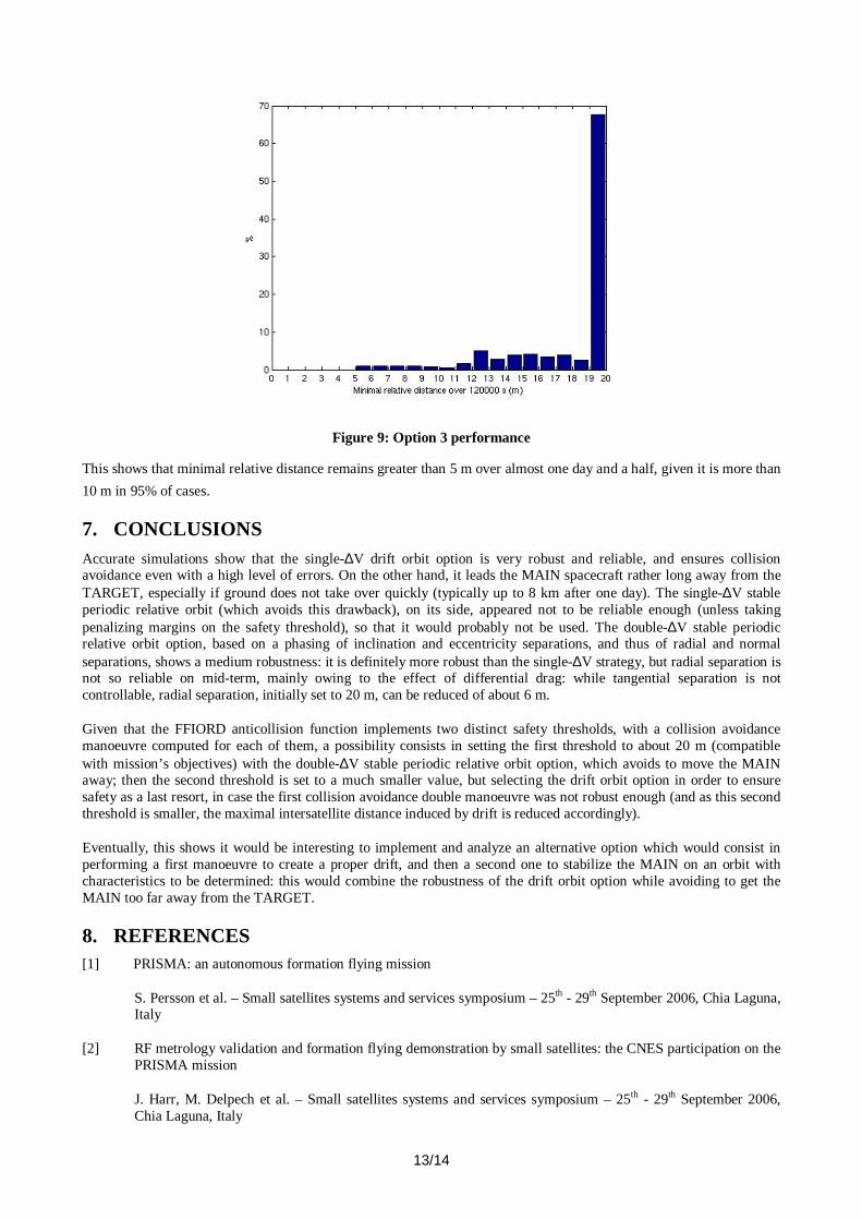
Figure 9: Option 3 performance
This shows that minimal relative distance remains greater than 5 m over almost one day and a half, given it is more than
10 m in 95% of cases.
7. CONCLUSIONS Accurate simulations show that the single-∆V drift orbit option is very robust and reliable, and ensures collision avoidance even with a high level of errors. On the other hand, it leads the MAIN spacecraft rather long away from the TARGET, especially if ground does not take over quickly (typically up to 8 km after one day). The single-∆V stable periodic relative orbit (which avoids this drawback), on its side, appeared not to be reliable enough (unless taking penalizing margins on the safety threshold), so that it would probably not be used. The double-∆V stable periodic relative orbit option, based on a phasing of inclination and eccentricity separations, and thus of radial and normal separations, shows a medium robustness: it is definitely more robust than the single-∆V strategy, but radial separation is not so reliable on mid-term, mainly owing to the effect of differential drag: while tangential separation is not controllable, radial separation, initially set to 20 m, can be reduced of about 6 m.
Given that the FFIORD anticollision function implements two distinct safety thresholds, with a collision avoidance manoeuvre computed for each of them, a possibility consists in setting the first threshold to about 20 m (compatible with mission’s objectives) with the double-∆V stable periodic relative orbit option, which avoids to move the MAIN away; then the second threshold is set to a much smaller value, but selecting the drift orbit option in order to ensure safety as a last resort, in case the first collision avoidance double manoeuvre was not robust enough (and as this second threshold is smaller, the maximal intersatellite distance induced by drift is reduced accordingly).
Eventually, this shows it would be interesting to implement and analyze an alternative option which would consist in performing a first manoeuvre to create a proper drift, and then a second one to stabilize the MAIN on an orbit with characteristics to be determined: this would combine the robustness of the drift orbit option while avoiding to get the MAIN too far away from the TARGET.
8. REFERENCES [1] PRISMA: an autonomous formation flying mission
S. Persson et al. – Small satellites systems and services symposium – 25th - 29th September 2006, Chia Laguna, Italy
[2] RF metrology validation and formation flying demonstration by small satellites: the CNES participation on the PRISMA mission
J. Harr, M. Delpech et al. – Small satellites systems and services symposium – 25th - 29th September 2006, Chia Laguna, Italy

14/14
[3] CNES formation flying experiment on PRISMA mission
M. Delpech et al. – 30th annual AAS guidance and control conference – 3rd-7th February 2007, Breckenridge, Colorado
[4] Spacecraft relative orbit geometry description through orbit element differences
H. Schaub – 14th US national congress of theoretical and applied mechanics – 23rd-28th June 2002, Blacksburg,, VA
[5] CNES approaching guidance experiment within FFIORD
J. –C. Berges et al. – 20th ISSFD – 24th-28th September 2007, Annapolis, Maryland