intro - fermilab muon departmentmuon.fnal.gov/personnel/leveling/requirements document... · web...
TRANSCRIPT

Preliminary Test Results, Dynamic Range Requirements, and TLM Electrometer
Requirements for Total Loss Monitor (TLM) Systems at Fermilab
A. Leveling, J. Anderson, P. Czarapata
Fermi National Accelerator Laboratory
10/5/12
IntroTotal Loss Monitors are being considered for use in Radiation Safety Systems at Fermilab to limit the intensity and duration of unintended beam losses. As we enter the intensity frontier, the requirement for passive shielding of existing and future accelerators and beam lines for the range of beam loss scenarios must be reexamined. For existing accelerators and beam lines, the tunnel structural design generally precludes the possibility of adding additional earth shielding. In cases, where additional shielding might be added, the additional of earth shielding could be of limited benefit and would be costly.
An alternative to the addition of earth shielding is the installation of fences and radiological postings. While fences and signs are a permitted option by the FRCM, these can be expensive to install, require continued vigilance to ensure that integrity is maintained. Weather elements including occasional high winds, rain, snow, and snow plowing are factors that make such vigilance necessary. Fences impede worker access to service buildings for equipment maintenance, impede worker access to shielding berms, and add a layer of complication and delays in the form of checking out keys, signing radiation work permits, etc.. Signs exposed to the elements often fade over time and require similar attention and occasional replacement.
In addition, the potential for worker exposure within posted areas is generally avoided by the imposition of the additional requirement that work is not permitted while beam is on; in essence, maintenance activities and beam operations cannot coexist. The coordination of operations and maintenance activities is complicated by this requirement. Also, as a consequence, accelerator/beam line maintenance activities are often delayed.

The laboratory is open to the public. In general, the impression of danger that radiation signs and fences produce for the uninformed public greatly outweighs the actual impact of radiation fields that might be present. The signs and barriers are used to control radiation exposure for workers and non-workers to the safe limits prescribed by various regulatory and guidance documents. The public perception of the purpose of the barriers and signs varies widely and is rarely coincident with their intended purposes. For this reason, the use of such barriers and signs should be limited if possible to cases where no alternative exists.
The use of thick passive shielding for new, powerful accelerators and beam lines is also impractical. Unlimited occurrences of very high beam power losses cannot be sustained. Orbit control of very high energy/ intensity is of utmost importance to prevent irreversible damage to costly accelerator beam line components. In the case of cryogenically cooled components such as certain RF cavities, low power losses must be automatically sensed. By their very nature, high power accelerators are self limiting in the extent and duration of beam loss. The role to be played by passive shielding needs to be defined in conjunction with these other inherent beam power loss limitations.
TLMs can be used to limit beam losses over extensive regions in accelerator/beam line enclosures. The applications for TLM use include the limitation of radiation dose rate outside of passive shielding, the limitation of radiation skyshine over extended areas, the control of residual radiation dose rate to workers due to beam loss within accelerator/beam line enclosures , and finally to limit activation of air, surface water and ground water.
A TLM requirements document has been prepared to describe general requirements for a TLM system. [Reference 1] The purpose of this document is to define the dynamic range requirements for the TLM system at Fermilab as well as the TLM electrometer performance requirements.
TLM Response TestingSeveral lengths of TLM including 125’, 250’, and 338’ have been installed in the Accumulator Debuncher Rings Enclosure beginning in June 2011. TLM testing progress and results are extensively documented in the 2011 PBAR Elog, entries 124, 170, and 194; and in the Muon Department Elog, entries #6 and #14.
TLM Operating ParametersTLM response can vary as a function of a number of operating parameters including the gas type, gas pressure, applied high voltage. In testing done to date, pure argon gas has been used at atmospheric pressure. Applied high voltage at 500 volts was found to be sufficient for linear response with controlled beam loss up to about 4E11 protons. For example, figure 1 shows the response for a 250’ and 338’ TLMs with a controlled beam loss on the magnet A2B7 in the Accumulator Ring. Figure 2 shows the response for 125’, 250’, and 338’ TLMs with a controlled beam loss on the Accumulator Extraction Lambertson Magnet.

At higher intensity beam loss (up to 3.5E12 protons), the applied voltage must be increased significantly in order to maintain linearity. Figure 3 shows the 338’ TLM response as a function of applied voltage for three different beam loss intensities. Figure 4 shows the same data normalized to beam intensity. As can be seen in Figure 4, a higher applied voltage is required to obtain a linear response for higher intensity beam losses.
To determine operating parameters for a TLM based safety system, dynamic range requirements for the intensity frontier must be considered.
Variation in TLM responseAs was shown in the previous section, TLM response for controlled beam losses are reproducible. However, the response varies fairly significantly however, as a function of loss distribution as can be seen in Figure 3. First, note that for a controlled beam loss at A2B7, the 250’ and 338’ TLM respond similarly with a response of about 3.2 nC/E10 protons. When the beam loss distribution is changed, it is important to note that the TLM response tends to increase for a given beam loss. The chipmunk response on the surface of the service building floor and on the berm above A2B7 can be seen in the right side image of Figure 5. During tune up, the beam loss is distributed in less massive objects relative to A2B7 which results in amplified TLM response. This is important. The TLM radiation safety system trip needs to be set for losses occurring in the most massive objects. Losses which subsequently occur is less massive objects will result in a conservative response of the TLM radiation safety system.
Also note that the cases shown in Figure 5 span two shielding regions which should be protected by separate TLM systems. The upstream section is located beneath the AP30 service building which has a ten foot radiation shield while the downstream section is the shielding berm which is 13 feet thick. Note that the majority of the beam loss occurs in all these various scenarios at A2B7, while the losses in the vicinity of ELAM are simply scraping beam loss. The majority of the chipmunk response occurs over the thinly shielded section where only a fraction of the beam is being lost. In the case of shielding applications, the TLM trip levels for respective sections they protect need to be set based upon losses in the most massive object which contributes to significant losses on the radiation shield surface. Losses in less massive objects tend to be distributed over much longer regions in the tunnel which would result in lower peak radiation dose rates on the surface.
TLM Applications The sensitivity of the TLM over a range of operating voltage and three decades of beam intensity has been observed preliminarily. At a sufficiently high voltage, approximately 2000 volts, the normalized response for 8 GeV beam with a beam loss of 3.5E12 protons is approximately 3.2 nC/E10 protons. The TLM response has also been correlated with radiation dose measured outside of the Accumulator/Debuncher shielding at two locations including a service building (10 foot shield) and a shielding berm (13 foot shielding). With this data, a Radiation Safety System protection scheme can be developed for high power beam applications (4 KW) in the Accumulator/Debuncher Rings enclosure.

However, continuation of TLM development work requires an understanding of the dynamic range requirements for other applications in the foreseeable future.
Scaling rules for beam energy can be applied to estimate TLM response at energies other than 8 GeV. For example, to scale TLM response at 120 GeV from 8 GeV, one could use the expression:
(E120/E8)0.8 X 3.2E10 nC/E10 protons = 28nC/E10 protons
The basis for determination of dynamic range is determined in a number of ways depending upon the application.
Shielding thickness basisOne could conservatively control beam losses to limit the normal condition radiation dose at the surface of a earth berm shield. For example, to limit the dose rate on the surface of the Main Injector berm to 0.05 mrem/hr due continuous beam loss at a single point, consider what proton beam intensity is required to produce a 1 mrem per hour dose rate. Using the shield scaling criteria,
Radiation Shielding Calculator
category energy intensity
cycle time (sec)
component to ceiling distance
1a 120 2.61E+13 1 5
Required shielding: 24.0 feet
a beam loss of 2.61E13 protons per second will produce a 1 mrem/hr dose rate if the magnet to ceiling distance is 5 feet. Dividing this proton intensity by 20 gives a proton intensity of 1.3E12 protons per second with a corresponding dose rate at the shielding berm surface of a maximum of 0.05 mrem/hr. (At this limit, no posting, barriers or other controls are required by the FRCM) .
A TLM mounted to the ceiling of the Main Injector tunnel would be approximately 5 feet from main injector magnets. Using the energy scaling factor described previously and scaling distance of the TLM from the 8 GeV reference case, a TLM would collected charge at the rate of:
1.3E12 ps×( 5.5 '5 ' )
2
×( 120GeV8GeV )0.8
× 3.2nCE10 p
=3,808nA

To limit the surface dose rate to 0.05 mrem/hr, the TLM electrometer output, connected to the radiation interlock card, would need to be set to limit charge current collection to 3.8 uA. This technique conservatively limits the surface dose rate to 0.05 mrem/hr assuming the loss is concentrated at a single point. If the loss is distributed over some greater distance, the surface dose rate is guaranteed to be << 0.05 mrem/hr. In addition to limiting the surface dose rate for the normal condition, the accident condition of 1 mrem/h is never realized. However, as will be shown below, a localized normal beam loss of this magnitude (25 KW!) could not be tolerated since the residual dose rate locally at the beam loss point would prohibit worker access.
Watt per meter basisA standard loss budget for an accelerator is often given as 1 watt/meter. This design goal is used to limit residual radiation levels in a beam or accelerator enclosure so that radiation exposure to workers can be kept at reasonably low levels. The average 120 GeV proton intensity equivalent to 1 watt per meter is 5.2E7 protons/m/s. The Main Injector is approximately 3500 meters in circumference. For an average 1 watt per meter beam loss around the Main Injector, a TLM system would collect charge at the rate of:
5.2E7 ps−m
×(5.5 '5 ' )2
×( 120GeV8GeV )0.8
× 3.2nCE10 p
×3,500m=615nA
One possible TLM system configuration for the Main Injector would consist of 12 individual systems. Two electrometers at each MI service building, i.e., MI10, MI20, MI30, MI40, MI50, and MI60, would serve two TLMs detectors. One detector would be placed in the clockwise direction and the other in the counterclockwise direction. The detectors would continue around the Main Injector to the midpoint of the next service building. With 12 TLMs and a limit of 615 nA, the trip limit for each TLM would be:
615 nA12
=51.3nA
This trip limit is only approximate. The actual length of the individual TLMs would determine the trip level while the sum of the trip levels would equal 615 nA. It is clear that the watt per meter basis for limiting beam loss in the Main Injector is much more conservative than the shielding thickness basis. Incorporating the watt per meter basis for the Main Injector would eliminate the need for further consideration of normal or accidental beam loss scenarios.
Radiation Skyshine BasisFor high intensity beam operations in thinly shielded beam enclosures, radiation skyshine may becomes a predominant concern. For example, for the proposed Mu2e experiment, it has been determined that a total beam loss of 10 watts distributed at the AP10, AP30, and AP50 service buildings must be observed in order to prevent radiation exposure to the visiting public at Fermilab. (This is very conservative since such a member of the public would need to be present

during Mu2e operation for 5555 hours per year!) Each of the service buildings is 216 feet long; each end of each building has a 24 foot section which contains the stairway which leads to tunnel enclosure. The effective length of the building which is a potential radiation skyshine source is 168 feet or 51 meters. The beam loss in the tunnel must be limited to:
3.3watts51meters
=0.065watts /meter
A 3.3 watt beam loss at 8 GeV is equivalent to 2.58E9 protons/seocnd. A radiation shielding measurement made at the extraction lambertson (ELAM) located at AP30 gave a peak radiation dose rate of about 25 mrem/3.6E13 protons. The peak radiation dose rate in the AP30 service building for a concentrated 3.3 watt beam loss is:
2.58E9 protonssecond
× 25mrem3.6E13 protons
=6.45 mremhr
A peak average dose rate of 6.45 mrem/hr would required the AP service buildings to be posted as Radiation Areas.
The TLM trip level for an Antiproton Ring service building would be based upon the watt/meter limit. The charge per E10 protons measured for TLMs for an 8 GeV beam loss on ELAM was about 6 nC/E10 protons. The electrometer trip level would be:
2.58E9 protonssecond
× 6nCE10 protons
=93nC /minute
Ground Water BasisThe NoVA experiment requires a 700 KW beam to be transported to the MI65 target hall while maintaining a 10 ppm beam loss to limit the activation of ground water. The equivalent beam intensity at 120 GeV is 3.65E13 protons per second. The total beam loss permitted for this operation is 3.65E8 protons per second. Assuming a TLM is placed in the tunnel along its entire length at a distance of 4 feet from the beam line, the TLM current limit would be:
3.65E8 protonssecond
× 3.2nCE10 protons
×( 120GeV8GeV )0.8
×(5.5'4 ' )2
=116 nC /minute
This current limit is independent of the length of the TLM.
Other basisSimilar techniques as those described above could be applied to TLMs to limit surface water and air activation, though these issues are usually less restrictive than most other radiological concerns.

TLM Dynamic Range Requirements A number of TLM applications including those discussed above have been considered and are listed in Table 1. The projected charge collection for 8 GeV cases is scaled from TLM measurements in the Accumulator/Debuncher Ring. The charge collection projection for Main Injector and other high energy applications is scaled for energy. The most demanding applications (highest charge collection rate) for the TLM dynamic range is for cases in which an enclosure, heavily shield region is being controlled for unlimited occupancy. The single point loss of beam power required to produce such a dose rate through a thick shielding berm is many KW. The TLM current limit would be as high as 10s of uA. Such an application of TLMs is unnecessary and unwarranted since continued operation with such losses would eventually lead to equipment damage or extraordinarily high residual dose rates. Such an application for the TLM is not recommended.
A more practical limitation is to limit the average losses to 1 watt per meter. In most the most challenging cases, e.g., limiting the Main Injector to 1 watt per meter, the TLM trip level is on the order of a few 10s of nA. The resulting residual dose rate resulting from such a loss should result in reasonable residual radiation dose rates in beam enclosure work spaces. In all but a few special cases (e.g., mu2e) , prompt radiation dose rates in accessible areas outside of beam enclosure would warrant no further attention.
TTL Pulse Definition The principal output signal from existing ion chambers (e.g., chipmunk) which is delivered to the Radiation Safety System is a TTL pulse. The TTL pulse represents a specific amount of charge of collected from the ion chamber. It is critically important for radiation dosimetry purposes that the value charge represented by the TTL pulse remain constant within some narrow tolerance. The tolerance which applies to the Chipmunk TTL pulse is +/- 1%. The overall acceptance of the chipmunk response during instrument calibration checks with a radiation source is +/- 10%. These same tolerances should be acceptable for the design of the TLM electrometer.
There are several systems which use the TTL pulse train from a RSS ion chamber. These include the site wide MUX system, the RSS, the RSS monitoring system, and ACNET. Of these systems, the site wide MUX system imposes the most severe limitations due to its 70 Hz sampling limitation. The site-wide MUX system is considered to be the main repository for collection of radiation dosimetry data measured by ion chambers used for personnel safety systems. This limitation is a driver for the determination of a TTL pulse.
In the preceding section, it was determined that the most challenging application for the TLM electrometer is the limitation of average beam loss to 1 W/m around the Main Injector. Assuming a uniform beam loss of 1 W/m around the MI with 12 TLMs, about 3,000 nC/minute-TLM would be the charge collection rate.

Since the maximum counting rate by the MUX system is 4200 TTL/minute and a reasonable upper control limit is 3000 nC/minute based on the MI, a value of 1 nC/TTL pulse appears to be a reasonable choice.
From the RSS interlock perspective, an electrometer output of 1 nC/ttl pulse is also reasonable. Although the radiation monitor interlock card opto-isolators can run up to 3.9 kHz, the micro-controller used to do the integration is a 16 bit processor. This limits the number of pulses that can be counted every 15 minutes to ~65,000. Setting the output to 1 nC/ttl pulse will limit the number of pulses seen by the radiation monitor interlock card for the MI scenario of 1W/m with 12 TLMs to 3080 counts per minute or 46,200 counts per 15 minute integration window.
The TLM ion chamber will be equipped with a 10 Tohm resistor to provide a constant current as described in Reference 2. The heartbeat resistor target level is 3 nC/min or about 3 TTL pulses per minute. This heartbeat resistor is intended to provide similar functionality used in the Chipmunk ion chamber where a Cs-137 source is used to provide a small positive ion chamber current. The heartbeat signal will be readily detectable in the absence of any beam loss signal.
Electrometer Time ConstantThe TLM electrometer must have a time constant to control the TTL pulse output. The relatively Instantaneous release of TTL pulses from a relatively large beam loss could be detected by the RSS and would safely initiate a RSS interlock trip. However the accurate recording of such an event by the MUX system could be missed due to the 70 Hz bandwidth limitation. The Chipmunk ion chamber electrometer output has an associated 20 second time constant which has worked well for the MUX system. A 20 second time constant is required for the TLM electrometer for the same purpose. A model of the TLM electrometer performance has been developed. [Reference 3]
References1. TLM Requirements Document, P. Czarapata, et. al., February 20122. TLM background signal, A. Leveling, August 20123. Revision 4 electrometer output worksheet, A. Leveling, October 2012

Figure 1 – 250’ and 338’ TLM response as a function of intentional beam loss at proton energy of 8 GeV into the Accumulator magnet A2B7

Figure 2 – 125’, 250’, and 338’ TLM response for a controlled beam loss on ELAM at 8 GeV
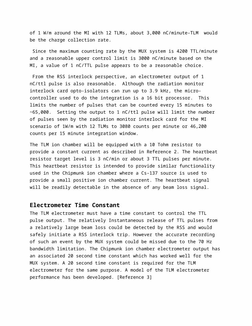
Figure 3 – 338’ TLM response as a function of voltage for three beam intensities: 2.3E10, 3.5E11, and 3.5E12 protons

Figure 4 – 338’ TLM response as a function of applied voltage for three beam intensities: 2.3E10, 3.5E11, and 3.5E12 protons
Figure 5 – TLM response for losses on A2B7 compared with TLM response during tune up. At left, Y scale units are nC and X scale units are E10 protons. At right is Chipmunk response during the tune up and study period shown at left.

8 GeV TLM response constant TLM baseline energy Energy scaling factor Baseline TLM distance to beam center
3.2nC/E10 8 GeV 0.8 5.5 feet
Machine/Condition Notes Beam power (KW)
Energy (GeV)
Protons per hour
Average intensity per
second
Nominal Shielding
feet
Magnet to ceiling
distance
Shield Category or application
basis
beam loss limit (p/s)
normal loss
limit p/s
% of beam loss
nC/min (per
meter in bold)
Mu2e Service Bldg. 1 4 8 1.13E+16 3.13E+12 10 5.5 skyshine 3.3 2.58E+0 0.082 93Mu2e Service Bldg. 1 8 8 2.25E+16 6.25E+12 10 5.5 skyshine 3.3 2.58E+0 0.041 93Mu2e Shielding 2 4 8 1.13E+16 3.13E+12 13 5.5 1A 3.26E+1 1.63E+0 0.052 31Mu2e Shielding 2 8 8 2.25E+16 6.25E+12 13 5.5 1A 3.26E+1 1.63E+0 0.026 31Booster May 2013 5 64 8 1.80E+17 5.00E+13 14 4 2A 2.20E+1 1.10E+1 0.022 399Booster 2016 5 80 8 2.25E+17 6.25E+13 14 4 2A 2.20E+1 1.10E+1 0.018 399Booster (any pwr) 3 8 14 4 1 W/m NA 4.69E+1 1,701Main Injector 2 700 120 1.31E+17 3.65E+13 24 5 1A 2.61E+1 1.31E+1 3.582 265,094Main Injector 2 2,300 120 4.31E+17 1.20E+14 24 5 1A 2.61E+1 1.31E+1 1.090 265,094Main Injector 3 700 120 1.31E+17 3.65E+13 24 5 1 W/m NA 1.82E+1 0.499 36,960Main Injector 3 2,300 120 4.31E+17 1.20E+14 24 5 1 W/m NA 1.82E+1 0.152 36,960Nova 2 700 120 1.31E+17 3.65E+13 26 3 1A 4.87E+1 2.44E+1 6.675 1,372,24LBNE 2 2,300 120 4.31E+17 1.20E+14 26 3 1A 4.87E+1 2.44E+1 2.030 1,372,24Nova 4 700 120 1.31E+17 3.65E+13 26 4 10 ppm NA 3.65E+0 0.001 116LBNE 4 2,300 120 4.31E+17 1.20E+14 26 3 1 W/m NA 5.21E+0 0.000 29
Not Recommended
Notes: 1 Distributed or concentrated loss limits public exposure to 1 mrem per year; NB – 6 nC/E10 at ELAM2 Single point loss limits berm surface normal condition dose rate to 0.05 mrem/hr
3 Total charge limit in tunnel beam loss to 1 W/m - distributed among some number of TLMs4 Limit total beam loss to 1 part in 1E55 Single point loss limits berm surface normal condition dose rate to 5 mrem/hr

Table 1