interstate 5 north coast corridor project · interstate 5 north coast corridor project san diego...
TRANSCRIPT

etric
Caltrans
Interstate 5 North Coast Corridor Project
SAN DIEGO COUNTY, CALIFORNIA 11 – SD – 5 – KP R45.7/R89.1 (PM R28.4/R55.4)
EA 235800
Draft Environmental Impact Report / Environmental Impact Statement
Prepared by the U.S. Department of Transportation Federal Highway Administration
and the State of California Department of Transportation
June 2010

- ii-I-5 North Coast Corridor Draft EIR/EIS
�

- i-I-5 North Coast Corridor Draft EIR/EIS
page i
GENERAL INFORMATION ABOUT THIS DOCUMENT What’s in this document: The California Department of Transportation (Caltrans) and the Federal Highway Administration (FHWA) have prepared this Draft Environmental Impact Report/Environmental Impact Statement (EIR/EIS), which examines the potential environmental impacts of the alternatives being considered for the proposed project located in San Diego County, California. The document describes why the project is being proposed, alternatives for the project, the existing environment that could be affected by the project, the potential impacts from each of the alternatives, and the proposed avoidance, minimization and/or mitigation measures.
What you should do: � Please read this Draft EIR/EIS. This document and the technical studies are available for review at
www.keepsandiegomoving.com/I-5-intro.html and the following locations: San Diego Public
Library Central 820 E Street San Diego, Ca 92101
San Diego County –Solana Beach
157 Stevens Avenue Solana Beach, CA
92075
Carlsbad Library 1775 Dove Lane Carlsbad, CA 92011
Caltrans District 11 4050 Taylor Street San Diego, CA 92110
San Diego Public
Library – Carmel Valley
3919 Townsgate Drive San Diego, CA 92130
Cardiff By The Sea Library
2081 Newcastle Avenue
Cardiff By The Sea, CA 92007
Georgina Cole Library 1250 Carlsbad Village
Drive Carlsbad, CA 92008
Del Mar Library 1309 Camino Del Mar Del Mar, CA 92014
Encinitas Library 540 Cornish Drive Encinitas, Ca 92024
Oceanside Public Library
330 N Coast Hwy Oceanside, CA 92054
� Attend one of 5 public Hearings:
Encinitas Location: Encinitas Community
and Senior Center – City of Encinitas
Room 142 Banquet Hall 1140 Oakcrest Park Drive Encinitas, CA 92024 Date: Tuesday, July 27, 2010
San Diego/Del Mar Location :Westfield UTC –
Forum Hall 4545 La Jolla Village Drive,
Suite E-25 San Diego CA, 92122-1212 Date: Tuesday, August 3, 2010
Carlsbad Location: City of Carlsbad -
Faraday Center Room 173A and 173B 1635 Faraday Ave Carlsbad, CA 92008 Date: Tuesday, August 17, 2010
Solana Beach Location: Skyline Elementary
School - Solana Beach School District
Activity Room 606 Lomas Santa Fe Drive Solana Beach, CA 92075-1400 Date: Tuesday, August 24, 2010
Oceanside Location: Oceanside High School
Oceanside Unified School District Multi-Purpose Room 1 Pirates Cove Oceanside, CA 92054 Date: Thursday, September 9, 2010
� We welcome your comments. If you have any comments regarding the proposed project, please attend
the public hearing and/or send your written comments to Caltrans by the deadline.
� Submit comments via postal mail to: Shay Lynn Harrison, Environmental Analysis Branch Chief CA Department of Transportation – District 11 Division of Environmental Analysis, MS 242 4050 Taylor Street San Diego, CA 92110
Submit comments via email to: [email protected]
� Submit comments by the deadline: October 7, 2010 What happens next: After comments are received from the public and reviewing agencies, Caltrans and the FHWA may undertake additional environmental and/or engineering studies. A Final EIR/EIS will be circulated; the Final EIR/EIS will include responses to comments received on the Draft EIR/EIS and will identify the preferred alternative. Following circulation of the Final EIR/EIS, if the decision is made to approve the project, a Notice of Determination will be published for compliance with the California Environmental Quality Act and a Record of Decision will be published for compliance with the National Environmental Policy Act. If the project is given environmental approval and funding is appropriated, Caltrans and FHWA could design and construct all or part of the project. For individuals with sensory disabilities, this document can be made available in Braille, large print, on audiocassette, or on computer disk. To obtain a copy in one of these alternate formats, please call or write to Caltrans, Attn: Shay Lynn Harrison, 4050 Taylor Street, San Diego, CA 92110 (MS242); (619) 688-0190 Voice, or use the or use the California Relay Service 1 (800) 735-2929 (TTY), 1 (800) 735-2929 (Voice) or 711.
It should be noted that at a future date FHWA may publish a notice in the Federal Register, pursuant to 23 USC §139(l), indicating that a final action has been taken on this project by FHWA. If such notice is published, a lawsuit or other legal claim will be barred unless it is filed within 180 days after the date of publication of the notice (or within such shorter time period as is specified in the Federal laws pursuant to which judicial review of the Federal agency action is allowed). If no notice is published, then the lawsuit or claim can be filed as long as the periods of time provided by other Federal laws that govern claims are met.

- ii-I-5 North Coast Corridor Draft EIR/EIS
page ii
�


- iv-
I-5 North Coast Corridor Draft EIR/EIS page iv
- iv-
�

I-5 North Coast Corridor Draft EIR/EIS page v
- v-
1
SUMMARY...........................................................................................................................S-1S.1 OVERVIEW OF PROJECT AREA ......................................................................................S-1S.2 PURPOSE AND NEED .......................................................................................................S-1S.3 ALTERNATIVES CONSIDERED ........................................................................................S-2S.4 JOINT CEQA/NEPA DOCUMENT......................................................................................S-3S.5 ENVIRONMENTAL CONSEQUENCES..............................................................................S-3
S.5.1 ENVIRONMENTAL CONSEQUENCES REMAINING SUBSTANTIAL AFTER MITIGATION (CEQA)..............................................................................................S-3
S.6 COORDINATION WITH THE PUBLIC AND OTHER AGENCIES......................................S-4S.7 AVOIDANCE, MINIMIZATION, AND/OR MITIGATION MEASURES ................................S-8S.8 OTHER PROJECTS AND CONSIDERATIONS ...............................................................S-16
CHAPTER 1 - PROPOSED PROJECT................................................................................ 1-11.1 INTRODUCTION ................................................................................................................. 1-11.2 PURPOSE FOR THE PROJECT ........................................................................................ 1-11.3 NEED FOR THE PROJECT................................................................................................ 1-2
1.3.1 EXISTING CIRCULATION SYSTEM AND INFRASTRUCTURE CONSTRAINTS 1-21.3.2 TRAFFIC DEMAND ................................................................................................ 1-31.3.3 POPULATION, HOUSING, AND EMPLOYMENT .................................................. 1-61.3.4 LEGISLATION ........................................................................................................ 1-71.3.5 MANAGED LANES................................................................................................. 1-71.3.6 OTHER I-5 PROJECTS .......................................................................................... 1-8
1.4 HISTORY AND BACKGROUND......................................................................................... 1-91.5 OTHER I-5 CONSIDERATIONS ....................................................................................... 1-11
CHAPTER 2 - PROJECT ALTERNATIVES......................................................................... 2-12.1 PROJECT DESCRIPTION .................................................................................................. 2-12.2 ALTERNATIVES ................................................................................................................. 2-1
2.2.1 COMMON DESIGN FEATURES OF THE BUILD ALTERNATIVES...................... 2-12.2.1 BUILD ALTERNATIVES ......................................................................................... 2-5
2.3 I-5 NORTH COAST COMMUNITY ENHANCEMENT PROJECTS..................................... 2-72.2.3 TRANSPORTATION SYSTEM MANAGEMENT (TSM), MULTI-MODAL AND
TRANSPORTATION DEMAND MANAGEMENT (TDM) ALTERNATIVES ......... 2-122.2.4 NO BUILD ALTERNATIVE ................................................................................... 2-12
2.4 PHASED CONSTRUCTION.............................................................................................. 2-132.5 ALTERNATIVES CONSIDERED BUT ELIMINATED FROM FURTHER DISCUSSION.. 2-15
2.5.1 REJECTED BUILD ALTERNATIVES................................................................... 2-152.6 PERMITS AND APPROVALS NEEDED........................................................................... 2-18
CHAPTER 3 – AFFECTED ENVIRONMENT, ENVIRONMENTAL CONSEQUENCES, AND AVOIDANCE, MINIMIZATION AND/OR MITIGATION MEASURES......... 3.1-1
HUMAN ENVIRONMENT.................................................................................................. 3.1-23.1 LAND USE ....................................................................................................................... 3.1-2
3.1.1 EXISTING AND FUTURE LAND USE ................................................................. 3.1-23.1.2 CONSISTENCY WITH STATE, REGIONAL AND LOCAL PLANS AND
PROGRAMS ...................................................................................................... 3.1-193.1.3 PARK AND RECREATIONAL FACILITIES ..................................................... 3.1-44
3.2 GROWTH..........................................................................................................................3.2-1
3.2.1 REGULATORY SETTING ....................................................................................3.2-13.2.2 AFFECTED ENVIRONMENT................................................................................3.2-13.2.2 ENVIRONMENTAL CONSEQUENCES ...............................................................3.2-23.2.3 AVOIDANCE, MINIMIZATION, AND/OR MITIGATION MEASURES..................3.2-3
3.3 FARMLANDS / AGRICULTURAL LANDS.......................................................................3.3-13.3.1 REGULATORY SETTING ....................................................................................3.3-13.3.2 AFFECTED ENVIRONMENT................................................................................3.3-13.3.3 ENVIRONMENTAL CONSEQUENCES ...............................................................3.3-23.3.4 AVOIDANCE, MINIMIZATION, AND/OR MITIGATION MEASURES..................3.3-3
3.4 COMMUNITY IMPACTS ...................................................................................................3.4-13.4.1 COMMUNITY CHARACTER AND COHESION ...................................................3.4-13.4.2 RELOCATIONS ....................................................................................................3.4-83.4.3 ENVIRONMENTAL JUSTICE.............................................................................3.4-10
3.5 UTILITIES AND EMERGENCY SERVICES .....................................................................3.5-13.5.1 AFFECTED ENVIRONMENT...............................................................................3.5-13.5.2 ENVIRONMENTAL CONSEQUENCES ...............................................................3.5-13.5.3 AVOIDANCE, MINIMIZATION, AND/OR MITIGATION MEASURES..................3.5-2
3.6 TRAFFIC & TRANSPORTATION / PEDESTRIAN & BICYCLE FACILITIES ....................3.6-13.6.1 REGULATORY SETTING ....................................................................................3.6-13.6.2 AFFECTED ENVIRONMENT................................................................................3.6-13.6.3 ENVIRONMENTAL CONSEQUENCES ...............................................................3.6-43.6.4 AVOIDANCE, MINIMIZATION, AND/OR MITIGATION MEASURES................3.6-11
3.7 VISUAL / AESTHETICS ...................................................................................................3.7-13.7.1 REGULATORY SETTING ....................................................................................3.7-13.7.2 AFFECTED ENVIRONMENT................................................................................3.7-13.7.3 ENVIRONMENTAL CONSEQUENCES .............................................................3.7-153.7.4 AVOIDANCE, MINIMIZATION, AND/OR MITIGATION MEASURES................3.7-37
3.8 CULTURAL RESOURCES...............................................................................................3.8-13.8.1 REGULATORY SETTING ....................................................................................3.8-13.8.2 AFFECTED ENVIRONMENT................................................................................3.8-13.8.3 ENVIRONMENTAL CONSEQUENCES ...............................................................3.8-33.8.4 AVOIDANCE, MINIMIZATION, AND/OR MITIGATION MEASURES..................3.8-4
PHYSICAL ENVIRONMENT.....................................................................................................3.9-1 3.9 HYDROLOGY / DRAINAGE (AND FLOODPLAINS) .......................................................3.9-1
3.9.1 REGULATORY SETTING ...................................................................................3.9-13.9.2 AFFECTED ENVIRONMENT...............................................................................3.9-13.9.3 ENVIRONMENTAL CONSEQUENCES ...............................................................3.9-63.9.4 AVOIDANCE, MINIMIZATION AND/OR MITIGATION MEASURES ..................3.9-9
3.10 WATER QUALITY AND STORM WATER RUNOFF .....................................................3.10-13.10.1 REGULATORY SETTING ..................................................................................3.10-13.10.2 AFFECTED ENVIRONMENT..............................................................................3.10-23.10.3 ENVIRONMENTAL CONSEQUENCES ............................................................3.10-83.10.4 AVOIDANCE, MINIMIZATION AND/OR MITIGATION MEASURES...............3.10-10
Table of Contents

I-5 North Coast Corridor Draft EIR/EIS page vi
- vi-
3.11 GEOLOGY / SOILS/ SEISMIC/ TOPOGRAPHY ........................................................... 3.11-13.11.1 REGULATORY SETTING.................................................................................. 3.11-13.11.2 AFFECTED ENVIRONMENT............................................................................. 3.11-13.11.3 ENVIRONMENTAL CONSEQUENCES............................................................. 3.11-33.11.4 AVOIDANCE, MINIMIZATION AND/OR MITIGATION MEASURES ................ 3.11-4
3.12 PALEONTOLOGY.......................................................................................................... 3.12-13.12.1 REGULATORY SETTING.................................................................................. 3.12-13.12.2 AFFECTED ENVIRONMENT............................................................................. 3.12-13.12.3 ENVIRONMENTAL CONSEQUENCES............................................................. 3.12-23.12.4 AVOIDANCE, MINIMIZATION, AND/OR MITIGATION MEASURES ............... 3.12-2
3.13 HAZARDOUS WASTE / MATERIALS........................................................................... 3.13-13.13.1 REGULATORY SETTING.................................................................................. 3.13-13.13.2 AFFECTED ENVIRONMENT............................................................................. 3.13-13.13.3 ENVIRONMENTAL CONSEQUENCES............................................................. 3.13-23.13.4 AVOIDANCE, MINIMIZATION, AND/OR MITIGATION MEASURES ............... 3.13-3
3.14 AIR QUALITY................................................................................................................. 3.14-13.14.1 REGULATORY SETTING.................................................................................. 3.14-13.14.2 AFFECTED ENVIRONMENT............................................................................. 3.14-13.14.3 ENVIRONMENTAL CONSEQUENCES............................................................. 3.14-13.14.4 AVOIDANCE, MINIMIZATION, AND/OR MITIGATION MEASURES ............. 3.14-10
3.15 NOISE............................................................................................................................. 3.15-13.15.1 REGULATORY SETTING.................................................................................. 3.15-13.15.2 AFFECTED ENVIRONMENT............................................................................ 3.15-23.15.3 ENVIRONMENTAL CONSEQUENCES............................................................ 3.15-33.15.4 AVOIDANCE, MINIMIZATION AND/OR MITIGATION MEASURES ................ 3.15-3
3.16 ENERGY......................................................................................................................... 3.16-13.16.1 REGULATORY SETTING.................................................................................. 3.16-13.16.2 AFFECTED ENVIRONMENT............................................................................. 3.16-13.16.3 ENVIRONMENTAL CONSEQUENCES............................................................. 3.16-13.16.4 AVOIDANCE, MINIMIZATION AND/OR MITIGATION MEASURES ................ 3.16-2
BIOLOGICAL ENVIRONMENT....................................................................................... 3.17-13.17 NATURAL COMMUNITIES............................................................................................ 3.17-1
3.17.1 AFFECTED ENVIRONMENT............................................................................. 3.17-13.17.2 ENVIRONMENTAL CONSEQUENCES............................................................. 3.17-53.17.3 AVOIDANCE, MINIMIZATION AND/OR MITIGATION MEASURES ................ 3.17-9
3.18 WETLANDS AND OTHER WATERS ........................................................................... 3.18-13.18.1 REGULATORY SETTING................................................................................. 3.18-13.18.2 AFFECTED ENVIRONMENT............................................................................. 3.18-13.18.3 ENVIRONMENTAL CONSEQUENCES............................................................. 3.18-33.18.4 AVOIDANCE, MINIMIZATION AND/OR MITIGATION MEASURES................ 3.18-4
3.19 PLANT SPECIES ........................................................................................................... 3.19-13.19.1 REGULATORY SETTING................................................................................. 3.19-13.19.2 AFFECTED ENVIRONMENT............................................................................. 3.19-13.19.3 ENVIRONMENTAL CONSEQUENCES............................................................ 3.19-23.19.4 AVOIDANCE, MINIMIZATION AND/OR MITIGATION MEASURES ................ 3.19-2
3.20 ANIMAL SPECIES.........................................................................................................3.20-13.20.1 REGULATORY SETTING ..................................................................................3.20-13.20.2 AFFECTED ENVIRONMENT..............................................................................3.20-13.20.3 ENVIRONMENTAL CONSEQUENCES .............................................................3.20-13.20.4 AVOIDANCE, MINIMIZATION AND/OR MITIGATION MEASURES.................3.21-3
3.21 THREATENED AND ENDANGERED SPECIES............................................................3.21-13.21.1 REGULATORY SETTING ..................................................................................3.21-13.21.2 AFFECTED ENVIRONMENT..............................................................................3.21-13.21.3 ENVIRONMENTAL CONSEQUENCES .............................................................3.21-43.21.4 AVOIDANCE, MINIMIZATION, AND/OR MITIGATION MEASURES................3.21-7
3.22 INVASIVE SPECIES.......................................................................................................3.22-13.22.1 REGULATORY SETTING ..................................................................................3.22-13.22.2 AFFECTED ENVIRONMENT..............................................................................3.22-13.22.3 ENVIRONMENTAL CONSEQUENCES .............................................................3.22-13.22.4 AVOIDANCE, MINIMIZATION AND/OR MITIGATION MEASURES.................3.22-1
3.23 RELATIONSHIP BETWEEN LOCAL SHORT-TERM USES OF THE HUMAN ENVIRONMENT AND THE MAINTENANCE AND ENHANCEMENT OF LONG-TERM PRODUCTIVITY......................................................................................3.24-1
3.24 IRREVERSIBLE AND IRRETRIEVABLE COMMITMENTS OF RESOURCES THAT WOULD BE INVOLVED IN THE PROPOSED PROJECT ............................................3.24-1
3.25 CUMULATIVE IMPACTS................................................................................................3.25-13.25.1 REGULATORY SETTING ..................................................................................3.25-13.25.2 CUMULATIVE ANALYSIS .................................................................................3.25-13.25.3 ENVIRONMENTAL CONSEQUENCES .............................................................3.25-13.25.4 AVOIDANCE, MINIMIZATION AND/OR MITIGATION MEASURES.................3.25-9
CHAPTER 4 – CALIFORNIA ENVIRONMENTAL QUALITY ACT EVALUATION.............. 4-14.1 DETERMINING SIGNIFICANCE UNDER CEQA ................................................................4-14.2 LESS THAN SIGNIFICANT EFFECTS OF THE PROPOSED PROJECT ..........................4-14.3 LESS THAN SIGNIFICANT IMPACTS WITH MITIGATION AND/OR MINIMIZATION ......4-1
4.3.1 NATURAL COMMUNITIES .....................................................................................4-14.3.2 NOISE ......................................................................................................................4-14.3.3 WETLANDS AND OTHER WATERS......................................................................4-2
4.4 UNAVOIDABLE SIGNIFICANT ENVIRONMENTAL EFFECTS .........................................4-24.4.1 VISUAL/AESTHETICS ............................................................................................4-24.4.2 COMMUNITY CHARACTER AND COHESION ......................................................4-2
4.5 SIGNIFICANT IRREVERSIBLE ENVIRONMENTAL CHANGES .......................................4-24.6 CLIMATE CHANGE.............................................................................................................4-24.7 MITIGATION MEASURES FOR SIGNIFICANT IMPACTS UNDER CEQA........................4-9
CHAPTER 5 – COMMENTS AND COORDINATION........................................................... 5-15.1 PROJECT SCOPING PROCESS ........................................................................................5-15.2 PROJECT DEVELOPMENT TEAM MEETINGS .................................................................5-25.3 NEPA – SECTION 404 INTEGRATION PROCESS ............................................................5-25.4 ADDITIONAL CONSULTATION AND COORDINATION WITH PUBLIC AGENCIES .......5-3
CHAPTER 6 – LIST OF PREPARERS ................................................................................ 6-1CHAPTER 7 – DISTRIBUTION LIST ................................................................................... 7-1

I-5 North Coast Corridor Draft EIR/EIS page vii
- vii-
List of Figures
Figure 1-1.1: Project Location Map............................................................................................................ 1-1Figure 1-3.1a-f: Average Daily Traffic Volumes for 2006 Conditions and
2030 No Build Alternative .................................................................................... 1-13 thru 18Figure 1-3.2a-f: Average Daily Traffic Volumes for 2030 8+4 Alternatives and
10+4 Alternatives ................................................................................................. 1-19 thru 24 Figure 2-2.1a: Typical IAP Barrier.............................................................................................................. 2-2Figure 2-2.1b: Typical IAP Buffer............................................................................................................... 2-2Figure 2-2.2: Typical DAR.......................................................................................................................... 2-3Figure 2-2.3: I-5 North Coast Managed Lanes Construction Initial Term Phasing Map .......................... 2-14Figure 2-2.4: I-5 North Coast Managed Lanes Construction Mid-Term Phasing Map............................. 2-14Figure 2-2.5: I-5 North Coast Managed Lanes Construction Long-Term Phasing Map........................... 2-15Figure 2-2.6: Schematic for 10+4 Barrier Alternative............................................................................... 2-19Figure 2-2.7: Schematic for 10+4 Buffer Alternative ................................................................................ 2-20Figure 2-2.8: Schematic for 8+4 Barrier Alternative................................................................................. 2-21Figure 2-2.9: Schematic for 8+4 Buffer Alternative .................................................................................. 2-22Figure 2-2.10: Cross Section for 10+4 Barrier and Buffer Alternative...................................................... 2-23Figure 2-2.11: Cross Section for 8+4 Barrier and Buffer Alternative........................................................ 2-24Figure 2-2.12: Cross Section for DAR for 10+4 Barrier and Buffer Alternative........................................ 2-25Figure 2-2.13: Cross Section with DAR for 8+4 Barrier and Buffer Alternative........................................ 2-26Figure 2-2.14a-ao: Project Features Map 10+4 Buffer Alternative .............................................. 2-27 thru 68Figure 3-1.1: Study Area Communities................................................................................................... 3.1-4Figure 3-1.2: San Diego/Del Mar Existing Land Use .............................................................................. 3.1-5Figure 3-1.3: San Diego/Del Mar Planned Land Use.............................................................................. 3.1-7Figure 3-1.4: Solana Beach/Encinitas Existing Land Use....................................................................... 3.1-8Figure 3-1.5: Solana Beach/Encinitas Planned Land Use ...................................................................... 3.1-9Figure 3-1.6: Carlsbad Existing Land Use ............................................................................................ 3.1-11Figure 3-1.7: Carlsbad Planned Land Use............................................................................................ 3.1-12Figure 3-1.8: Oceanside Existing Land Use .......................................................................................... 3.1-14Figure 3-1.9: Oceanside Planned Land Use......................................................................................... 3.1-15Figure 3-1.10: Park and Recreational Facilities ..................................................................................... 3.1-43Figure 3-3.1: Important Farmlands – North............................................................................................. 3.3-4Figure 3-3.2: Important Farmlands – South ............................................................................................ 3.3-5Figure 3-4.1: Build Alternatives Right–of–Way Comparison: South of Carlsbad Village Drive ............... 3.4-7Figure 3-4.2: Block Groups Containing Low-Income and Minority Populations – North ....................... 3.4-15Figure 3-4.3: Block Groups Containing Low-Income and Minority Populations – South....................... 3.4-16Figure 3-6.1: Level of Service .................................................................................................................. 3.6-2Figure 3-7.1: Landscape Units Map........................................................................................................ 3.7-2Figure 3-7.2: Looking north to Voigt Drive overcrossing.......................................................................... 3.7-3Figure 3-7.3: Freeway landscaping blends with that of UCSD near Voigt Drive..................................... 3.7-3Figure 3-7.4: Looking north to the freeway and Sorrento Valley beyond................................................ 3.7-3Figure 3-7.5: Looking north from northbound I-5 at Genesee Avenue ................................................... 3.7-3Figure 3-7.6: A distant view of the ocean and Los Peñasquitos Lagoon from northbound I-5................ 3.7-4
Figure 3-7.7: A distant view of I-5 from Torrey Pines State Reserve.......................................................3.7-4Figure 3-7.8: Looking north to Del Mar Heights Road .............................................................................3.7-4Figure 3-7.9: Looking south from the Del Mar Heights Road overcrossing .............................................3.7-4Figure 3-7.10: Looking southwest from I-5 towards San Dieguito Lagoon and the bluffs of Del Mar......3.7-5Figure 3-7.11: Looking northeast from I-5 towards San Dieguito Lagoon ................................................3.7-5Figure 3-7.12: A view of the ocean and Del Mar Racetrack from southbound I-5 ...................................3.7-5Figure 3-7.13: A view of the sandstone slopes and northbound I-5, south of Lomas Santa Fe Drive.....3.7-5Figure 3-7.14: Distant view to eastern foothills from northbound I-5, south of Manchester Avenue .......3.7-6Figure 3-7.15: View of San Elijo Lagoon, agricultural fields and sandstone bluffs from the shoulder
of northbound I-5, just south of Manchester Avenue......................................................3.7-6Figure 3-7.16: A view of I-5 looking south ...............................................................................................3.7-6Figure 3-7.17: Looking southwest from the Birmingham Drive overcrossing ..........................................3.7-6Figure 3-7.18: Natural open space along the northbound lanes of I-5 ....................................................3.7-6Figure 3-7.19: Wetland vegetation buffers the adjacent community from I-5 ..........................................3.7-7Figure 3-7.20: Northbound I-5, looking north toward Requeza Street overcrossing................................3.7-7Figure 3-7.21: Looking northwest across I-5 from MacKinnon Drive overcrossing ................................3.7-7Figure 3-7.22: Looking west from southbound I-5, a residential area at Orpheus Street ........................3.7-7Figure 3-7.23: Commercial greenhouses and open space lots characterize this landscape unit............3.7-7Figure 3-7.24: Batiquitos Lagoon as seen from southbound I-5..............................................................3.7-8Figure 3-7.25: A view of Batiquitos Lagoon and I-5, looking southeast...................................................3.7-8Figure 3-7.26: Commercial development bordering southbound I-5 .......................................................3.7-8Figure 3-7.27: Commercial development bordering southbound I-5 .......................................................3.7-8Figure 3-7.28: A naturalized drainage channel buffers northbound I-5 from nearby residences.............3.7-8Figure 3-7.29: A view of Agua Hedionda Lagoon from northbound I-5 ...................................................3.7-9Figure 3-7.30: A view of Agua Hedionda Lagoon from the southbound lanes ........................................3.7-9Figure 3-7.31: A view of Pine Street looking west to the freeway and ocean..........................................3.7-9Figure 3-7.32: Holiday Park as seen from the shoulder of northbound I-5 ..............................................3.7-9Figure 3-7.33: View of I-5 at Buena Vista Lagoon, looking northwest ...................................................3.7-10Figure 3-7.34: View of I-5 at Buena Vista Lagoon, looking northeast....................................................3.7-10Figure 3-7.35: Mature freeway landscaping establishes the parkway character of the viewshed .........3.7-10Figure 3-7.36: Mature freeway landscaping establishes the parkway character of the viewshed .........3.7-10Figure 3-7.37: Freeway landscaping provides a visual buffer and improves visual quality of the
landscape unit ...............................................................................................................3.7-11Figure 3-7.38: Freeway landscaping provides a visual buffer and improves visual quality of the
landscape unit ...............................................................................................................3.7-11Figure 3-7.39: A view of I-5 from the San Luis Rey River bike trail .......................................................3.7-11Figure 3-7.40: Plentiful landscaping forms a visual gateway to the San Diego region, as viewed
from southbound I-5. ....................................................................................................3.7-11Figure 3-7.41: Key View Map ................................................................................................................3.7-16Figure 3-7.42: Key View #1 - Voigt Drive: Existing view looking south..................................................3.7-17Figure 3-7.43: Key View #1 - Voigt Drive: Proposed view looking south...............................................3.7-17Figure 3-7.44: Key View #2 - I-5 at Del Mar Heights Road: Existing view looking north .......................3.7-18Figure 3-7.45: Key View #2 - I-5 at Del Mar Heights Road: Proposed view looking north ....................3.7-18Figure 3-7.46: Key View #3 - Ida Avenue: Existing view looking north..................................................3.7-19Figure 3-7.47: Key View #3 - Ida Avenue: Proposed view looking north...............................................3.7-19Figure 3-7.48: Key View #4 - I-5 at Ida Avenue: Existing view looking southwest ................................3.7-20

I-5 North Coast Corridor Draft EIR/EIS page viii
- viii-
Figure 3-7.49: Key View #4 - I-5 at Ida Avenue: Proposed view looking southwest ............................. 3.7-20Figure 3-7.50: Key View #5 - I-5 at Manchester Avenue: Existing view looking north .......................... 3.7-21Figure 3-7.51: Key View #5 - I-5 at Manchester Avenue: Proposed view looking north ....................... 3.7-21Figure 3-7.52: Key View #6 - Devonshire Drive in Encinitas: Existing view looking north .................... 3.7-22Figure 3-7.53: Key View #6 - Devonshire Drive in Encinitas: Proposed view looking north ................. 3.7-22Figure 3-7.54: Key View #7 - I-5 at Encinitas Boulevard: Existing view looking north .......................... 3.7-23Figure 3-7.55: Key View #7 - I-5 at Encinitas Boulevard: Proposed view looking north ....................... 3.7-23Figure 3-7.56: Key View #8 - Union Street in Encinitas: Existing view looking east at I-5 .................... 3.7-24Figure 3-7.57: Key View #8 - Union Street in Encinitas: Proposed view looking east at I-5 ................. 3.7-24Figure 3-7.58: Key View #9 - I-5 Near Union Street: Existing view looking south................................. 3.7-25Figure 3-7.59: Key View #9 - I-5 Near Union Street: Proposed view looking south.............................. 3.7-25Figure 3-7.60: Key View #10 - Union Street in Encinitas: Existing view looking southeast .................. 3.7-26Figure 3-7.61: Key View #10 - Union Street in Encinitas: Proposed view looking southeast ............... 3.7-26Figure 3-7.62: Key View #11 - Orpheus Avenue in Encinitas: Existing view looking north................... 3.7-27Figure 3-7.63: Key View #11 - Orpheus Avenue in Encinitas: Proposed view looking north ................ 3.7-27Figure 3-7.64: Key View #12 - I-5 at Carlsbad Village Drive: Existing view looking north .................... 3.7-28Figure 3-7.65: Key View #12 - I-5 at Carlsbad Village Drive: Proposed view looking north.................. 3.7-28Figure 3-7.66: Key View #13 - Holiday Park in Carlsbad: Existing view looking north.......................... 3.7-29Figure 3-7.67: Key View #13 - Holiday Park in Carlsbad: Proposed view looking north....................... 3.7-29Figure 3-7.68: Key View #13A - Holiday Park in Carlsbad: Existing view looking southwest ............... 3.7-29Figure 3-7.69: Key View #13A - Holiday Park in Carlsbad: Proposed view looking southwest ............ 3.7-29Figure 3-7.70: Key View #14 - I-5 at Carlsbad Village Drive: Existing view looking north .................... 3.7-31Figure 3-7.71: Key View #14 - I-5 at Carlsbad Village Drive: Proposed view looking north.................. 3.7-31Figure 3-7.72: Key View #15 - Pine Street in Carlsbad: Existing view adjacent to (west of) I-5 ........... 3.7-32Figure 3-7.73: Key View #15 - Pine Street in Carlsbad: Proposed view adjacent to (west of) I-5 ........ 3.7-32Figure 3-7.74: Key View #16 - I-5 at Oceanside Boulevard DAR: Existing view looking south ............ 3.7-33Figure 3-7.75: Key View #16 - I-5 at Oceanside Boulevard DAR: Proposed view looking south.......... 3.7-33Figure 3-7.76: Key View #16 - I-5 at Oceanside Boulevard DAR: Existing view looking west.............. 3.7-34Figure 3-7.77: Key View #16 - I-5 at Oceanside Boulevard DAR: Proposed view looking west ........... 3.7-34Figure 3-7.78: Visual Impact Summary Map......................................................................................... 3.7-36Figure 3-7.79: Scenic Resource Impacts Map...................................................................................... 3.7-37Figure 3-7.80: Soundwall buffer planting section.................................................................................. 3.7-38Figure 3-7.81: Soundwall articulated layout/varied profileSoundwall planting pockets......................... 3.7-38Figure 3-7.82: Soundwall planting pocket section ................................................................................ 3.7-38Figure 3-7.83: Berm in fill section ......................................................................................................... 3.7-38Figure 3-7.84: Berm in cut section ........................................................................................................ 3.7-39Figure 3-7.85: Noise berm/retaining wall section.................................................................................. 3.7-39Figure 3-7.86: Noise berm/ noise wall combination section.................................................................. 3.7-39Figure 3-7.87: Soundwall setback section ............................................................................................ 3.7-39Figure 3-7.88: Vertical concrete safety barrier section ......................................................................... 3.7-40Figure 3-7.89: Transparent soundwall section...................................................................................... 3.7-40Figure 3-7.90: Terrain contoured wall in cut section (Plan View).......................................................... 3.7-40Figure 3-7.91: Terrain contoured wall in cut section (Elevation View) .................................................. 3.7-41Figure 3-7.92: Terraced retaining walls section .................................................................................... 3.7-41Figure 3-7.93: Mid-slope retaining wall section..................................................................................... 3.7-41Figure 3-7.94: Top-of-slope retaining wall section ................................................................................ 3.7-41
Figure 3-7.95: Viaduct retaining wall (Elevation View) ..........................................................................3.7-42Figure 3-7.96: Viaduct retaining wall (Section View) .............................................................................3.7-42Figure 3-7.97: Retaining wall/planting pocket section ...........................................................................3.7-42Figure 3-7.98: Barrier setback section...................................................................................................3.7-43Figure 3-7.99: Vertical concrete safety barrier section ..........................................................................3.7-43Figure 3-7.100: Battered wall face section ............................................................................................3.7-43Figure 3-7.101: Southbound/Northbound cut wall, elevation & section.................................................3.7-44Figure 3-7.102: An MSE wall with a 4 in pattern reveal.........................................................................3.7-44Figure 3-7.103: An example of a short seat abutment...........................................................................3.7-44Figure 3-7.104: Secondary walls such as this reduce visual unity and should be avoided ...................3.7-44Figure 3-7.105: A wider sidewalk would enable these pedestrians to walk side by side.......................3.7-45Figure 3-7.106: Sidewalk barrier separation section .............................................................................3.7-45Figure 3-7.107: An example of pedestrian amenities on the I-15/El Cajon Boulevard overcrossing.....3.7-45Figure 3-7.108: Encinitas Boulevard undercrossing pedestrian and bicycle access could be
improved........................................................................................................................3.7-46Figure 3-7.109: Undercrossings-pedestrian sidewalks and bicycle lanes section.................................3.7-46Figure 3-7.110: A lighting concept for Lomas Santa Fe Drive undercrossing integrates function and
aesthetics ......................................................................................................................3.7-46Figure 3-7.111: Type 80 bridge rail .......................................................................................................3.7-46Figure 3-7.112: Seating, lighting and community identity elements enhance this pedestrian
overcrossing entry .........................................................................................................3.7-47Figure 3-7.113: DAR (Elevation View)...................................................................................................3.7-47Figure 3-7.114: DAR (Plan View) ..........................................................................................................3.7-47Figure 3-7.115: A sidewalk along an I-15 freeway offramp becomes a pedestrian realm with
the inclusion of human scale street amenities...............................................................3.7-48Figure 3-7.116: Pedestrians walking in the realm of the automobile. ....................................................3.7-48Figure 3-7.117: Concept sketch for a BRT station proposed along the I-15 corridor ............................3.7-49Figure 3-9.1: Soledad Canyon Creek Floodplain within the project area ..............................................3.9-11Figure 3-9.2: Los Peñasquitos Creek Floodplain within the Project Area..............................................3.9-12Figure 3-9.3: Carmel Valley Creek Floodplain within the Project Area..................................................3.9-13Figure 3-9.4: San Dieguito River Floodplain within the Project Area.....................................................3.9-14Figure 3-9.5: San Elijo Lagoon Floodplain within the Project Area........................................................3.9-15Figure 3-9.6: Cottonwood Creek Floodplain within the Project Area .....................................................3.9-16Figure 3-9.7: Batiquitos Lagoon Floodplain within the Project Area ......................................................3.9-17Figure 3-9.8: Encinas Creek Floodplain within the Project Area ...........................................................3.9-18Figure 3-9.9: Agua Hedionda Lagoon Floodplain within the Project Area.............................................3.9-19Figure 3-9.10: Buena Vista Lagoon Floodplain within the Project Area ................................................3.9-20Figure 3-9.11: Loma Alta Creek Floodplain within the Project Area ......................................................3.9-21Figure 3-9.12: San Luis Rey River Floodplain within the Project Area ..................................................3.9-22Figure 3-10.1: Surface Streams and Floodplains within the Project Limits ...........................................3.10-2Figure 3-10.2: Hydrologic Units within the I-5 NCC project ...................................................................3.10-3Figure 3-13.1: Hazardous Materials for High and Medium Risk- North .................................................3.13-4Figure 3-13.2: Hazardous Materials for High and Medium Risk- South ................................................3.13-5Figure 3-14.1: Changes in Diesel PM....................................................................................................3.14-8Figure 3-14.2: Changes in Benzene Emission ......................................................................................3.14-8Figure 3-14.3: Changes in Butadiene Emission ....................................................................................3.14-8

I-5 North Coast Corridor Draft EIR/EIS page ix
- ix-
Figure 3-14.4: Changes in Acetaldehyde Emission .............................................................................. 3.14-8Figure 3-14.5: Changes in Acrolein Emission....................................................................................... 3.14-8Figure 3-14.6: Changes in Formaldehyde Emission............................................................................. 3.14-8Figure 3-15.1: Typical A-Weighted Noise Levels.................................................................................. 3.15-1Figure 3-17. 1a-m: Vegetation Communities .......................................................................... 3.17-10 thru 22Figure 3-17.2: Eelgrass Coverage ...................................................................................................... 3.17-23Figure 3-18.1a-h: ACOE Jurisdictional Waters ......................................................................... 3.18-5 thru 12Figure 3-19.1a-e: Sensitive Plant Locations ............................................................................... 3.19-3 thru 7Figure 3-20.1a-e: Sensitive Wildlife Locations............................................................................ 3.20-4 thru 8Figure 3-21.1a-d: Critical Habitat ............................................................................................ 3.21-10 thru 13Figure 3-25.1: Approximate Locations of Cumulative Projects ............................................................. 3.25-2Figure 3-25.2: Cumulative Projects within Visual Resources RSA ....................................................... 3.25-5Figure 3-25.3: Cumulative Projects within Natural Communities RSA................................................... 3.25-6Figure 3-25.4: Cumulative Projects within Wetlands and Other Waters RSA....................................... 3.25-7Figure 5-1.1: Notice of Preparation............................................................................................................ 5-5Figure 5-1.2: Notice of Intent ..................................................................................................................... 5-5Figure 5-3.1: USFWS Concurrence with Purpose and Need..................................................................... 5-6Figure 5-3.2: NOAA/NMFS Concurrence on Purpose and Need............................................................... 5-6Figure 5-3.3: ACOE Concurrence with Purpose and Need ....................................................................... 5-7Figure 5-3.4: EPA Concurrence with Purpose and Need .......................................................................... 5-7Figure 5-3.5: USFWS Concurrence with Range of Alternatives ................................................................ 5-8Figure 5-3.6: NOAA/NMFS Concurrence with Range of Alternatives ........................................................ 5-9Figure 5-3.7: ACOE Concurrence with Range of Alternatives ................................................................... 5-9Figure 5-3.8: EPA Concurrence with Range of Alternatives .................................................................... 5-10Figure 5-3.9: USFWS Concurrence with Range of Alternatives .............................................................. 5-10Figure 5-3.10: NOAA/NMFS Concurrence with Criteria Matrix ................................................................ 5-11Figure 5-3.11: ACOE Concurrence with Criteria Matrix ........................................................................... 5-11Figure 5-3.12: EPA Concurrence with Criteria Matrix .............................................................................. 5-12Figure 5-4.1: SHPO Concurrence............................................................................................................ 5-13Figure 5-4.2: USFWS Listed Endangered, Threatened and Proposed Species...................................... 5-14Figure 5-4.3: ACHP Response to Undertaking Notification ..................................................................... 5-15
List of Tables Table S.1: Summary of Major Potential Impacts by Alternative.................................................................. S-5Table S.2: Permits and Approvals Needed................................................................................................ S-7Table S.3: Recommended Noise Barriers ............................................................................................... S-12Table S.4: Potential Mitigation Sites......................................................................................................... S-13Table 1.3.1: Annual Average Daily Traffic (ADT)........................................................................................1-3Table 1.3.2: Average Travel Time Northbound AM and PM.......................................................................1-4Table 1.3.3: Average Travel Time Southbound AM and PM ......................................................................1-4Table 1.3.4: Northbound AM and PM Weekday Peak Hour Congestion ....................................................1-4Table 1.3.5: Southbound AM and PM Weekday Peak Hour Congestion ...................................................1-4Table 1.3.6: Weekday Northbound HOV Volumes .....................................................................................1-5Table 1.3.7: Weekday Southbound HOV Volumes ....................................................................................1-5Table 1.3.8: Project Area Population by Jurisdiction, Project Area, 1970 to 2000 .....................................1-6Table 1.3.9: Total Population Housing and Employment, North Coast Travel Shed ..................................1-6Table 1.3.10: Project Area Employment by Jurisdiction .............................................................................1-6Table 1.3.11: LOSSAN San Diego Projects ...............................................................................................1-8Table 1.5.1: On-going Lagoon Restoration Efforts ...................................................................................1-12Table 2.1: Interchange/Ramp Reconfiguration...........................................................................................2-4Table 2.2: Structure Replacements and Widenings ...................................................................................2-6Table 2.3: Permits and Approvals Needed...............................................................................................2-18Table 3.1.1: Project Consistency with Local Plans and Policies.............................................................3.1-26Table 3.2.1: Remaining Developable Hectares (Acres) as of 2004.........................................................3.2-1Table 3.2.2: Population Growth Projections for Jurisdictions within the Study Area ...............................3.2-1Table 3.3.1: Farmland Conversion Impact Rating ...................................................................................3.2-3Table 3.4.1: Relocation Associated with the10+4 with Barrier Alternative ...............................................3.4-8Table 3.4.2: Relocation Associated with the10+4 with Buffer Alternative.................................................3.4-9Table 3.4.3: Relocation Associated with the 8+4 with Barrier Alternative ................................................3.4-9Table 3.4.4: Relocation Associated with the 8+4 with Buffer Alternative................................................3.4-10Table 3.4.5: Study Area Race, Ethnicity, and Proportion of Total Minority............................................3.4-12Table 3.4.6: Study Area Population Below the Poverty Level (1999) ....................................................3.4-13Table 3.5.1: Utilities Over 50 kV ..............................................................................................................3.5-2Table 3.6.1: Average Daily Traffic (ADT).................................................................................................3.6-4Table 3.6.2: Total Delay, Congested Hours, and Travel Time.................................................................3.6-5Table 3.6.3: Northbound AM and PM Weekday Peak Period Congestion Duration................................3.6-5Table 3.6.4: Southbound AM and PM Weekday Peak Period Congestion Duration ...............................3.6-5Table 3.6.5: Northbound I-5 Estimated General-purpose Lane LOS Summary ......................................3.6-6Table 3.6.6: Southbound I-5 Estimated General-purpose Lane LOS Summary......................................3.6-6Table 3.6.7: Weekday Northbound HOV Volumes ..................................................................................3.6-7Table 3.6.8: Weekday Southbound HOV Volumes .................................................................................3.6-7Table 3.6.9: Current Intersections At or Over Capacity ...........................................................................3.6-8Table 3.6.10: Proposed Interchange Improvements ...............................................................................3.6-8Table 3.6.11: I-5 HOV/Managed Lanes Estimated Annual Revenue ......................................................3.6-9Table 3.9.1: 100-Year Floodplain Impacts Comparison ........................................................................3.9-10Table 3.10.1: Beneficial Use Definitions................................................................................................3.10-4

I-5 North Coast Corridor Draft EIR/EIS page x
- x-
Table 3.10.2: Beneficial Uses for Inland Surface Waters ..................................................................... 3.10-5Table 3.10.3: Beneficial Uses for coastal Surface Waters.................................................................... 3.10-5Table 3.10.4: Beneficial Uses for Ground Waters................................................................................. 3.10-5Table 3.10.5: Project Area CWA Section 303(d) List of Water Quality Limited Segments & TDCs...... 3.10-6Table 3.10.6: List of Water Bodies Addressed in TMDLs & Responsible Stakeholders ....................... 3.10-6Table 3.10.7: Existing I-5 Contribution to the Watershed within the project limits ................................ 3.10-8Table 3.10.8: Comparison of existing and proposed pavement areas between the Build Alternatives 3.10-8Table 3.10.9: Temporary Disturbed Soil Areas (DSAs) for the Build Alternatives ................................ 3.10-9Table 3.10.10: BMP Categories and Description................................................................................ 3.10-10Table 3.10.11: Design Pollution Prevention BMPs (MEP Based), Category IB.................................. 3.10-10Table 3.10.12: Construction BMP Categories..................................................................................... 3.10-10Table 3.10.13 Approved Treatment BMPs (Category III).................................................................... 3.10-11Table 3.13.1: Bridge/Intersection with potential for hazardous waste................................................... 3.13-2Table 3.14.1. Ambient Air Quality Standards....................................................................................... 3.14-.2Table 3.14.2: Federal and State Criteria Pollutant Attainment Status for San Diego Air Basin ............ 3.14-3Table 3.14.3: Federal Nonattainment and Attainment/Maintenance Pollutants in the SDAB ............... 3.14-3Table 3.14.4: Sensitive Receptors ........................................................................................................ 3.14-3Table 3.14.5: Estimated CO Concentration Hotspot Modeling Results ................................................ 3.14-5Table 3.14.6: PM10 and PM2.5 Trends at the San Diego 12th Avenue Monitoring Station ..................... 3.14-6Table 3.14.7: Traffic Activity Data for I-5 NCC Project.......................................................................... 3.14-7Table 3.14.8: 2015 Changes (�) in Total Project MSAT Emission Rates............................................. 3.14-7Table 3.14.9: 2030 Changes (�) in Total Project MSAT Emission Rates............................................. 3.14-8Table 3.14.10: Land Uses within I-5 Segments .................................................................................... 3.14-8Table 3.15.1: Noise Abatement Criteria................................................................................................ 3.15-1Table 3.15.2: Roadway Segmental Distribution.................................................................................... 3.15-2Table 3.15.3: Predicted Future Noise Levels and Soundwall Feasibility for Segment 1....................... 3.15-4Table 3.15.4: Summary of Feasible Soundwalls and Preliminary Abatement Decision
for Segment 1 ................................................................................................................. 3.15-4Table 3.15.5: Predicted Future Noise Levels and Soundwall Feasibility for Segment 2............... 3.15-3.15-5Table 3.15.6: Summary of Feasible Soundwalls and Preliminary Abatement Decision
for Segment 2 ................................................................................................................. 3.15-5Table 3.15.7: Predicted Future Noise Levels and Soundwall Feasibility for Segment 3....................... 3.15-6Table 3.15.8: Summary of Feasible Soundwalls and Preliminary Abatement Decision
for Segment 3 ................................................................................................................. 3.15-7Table 3.15.9: Predicted Future Noise Levels and Soundwall Feasibility for Segment 4....................... 3.15-8Table 3.15.10: Summary of Feasible Soundwalls and Preliminary Abatement Decision
for Segment 4 ............................................................................................................... 3.15-9Table 3.15.11: Predicted Future Noise Levels and Soundwall Feasibility for Segment 5................... 3.15-11Table 3.15.12: Summary of Feasible Soundwalls and Preliminary Abatement Decision
for Segment 5 ............................................................................................................. 3.15-12Table 3.15.13: Predicted Future Noise Levels and Soundwall Feasibility for Segment 6................... 3.15-14Table 3.15.13: Predicted Future Noise Levels and Soundwall Feasibility for Segment 6 (Option 2).. 3.15-15Table 3.15.14: Summary of Feasible Soundwalls and Preliminary Abatement Decision
for Segment 6 ............................................................................................................ 3.15-15Table 3.15.15: Predicted Future Noise Levels and Soundwall Feasibility for Segment 7................... 3.15-17Table 3.15.15: Predicted Future Noise Levels and Soundwall Feasibility for Segment 7 (Option 2).. 3.15-18
Table 3.15.16: Summary of Feasible Soundwalls and Preliminary Abatement Decision for Segment 7 ..............................................................................................................3.15-18
Table 3.15.17: Predicted Future Noise Levels and Soundwall Feasibility for Segment 8 ...................3.15-20Table 3.15.18: Summary of Feasible Soundwalls and Preliminary Abatement Decision
for Segment 8 ..............................................................................................................3.15-21Table 3.15.19: Predicted Future Noise Levels and Soundwall Feasibility for Segment 9 ...................3.15-22Table 3.15.20: Summary of Feasible Soundwalls and Preliminary Abatement Decision
for Segment 9 ..............................................................................................................3.15-23Table 3.15.21: Predicted Future Noise Levels and Soundwall Feasibility for Segment 10 .................3.15-25Table 3.15.22: Summary of Feasible Soundwalls and Preliminary Abatement Decision
for Segment 10............................................................................................................3.15-26Table 3.15.23: Predicted Future Noise Levels and Soundwall Feasibility for Segment 11 .................3.15-28Table 3.15.24: Summary of Feasible Soundwalls and Preliminary Abatement Decision
for Segment 11............................................................................................................3.15-30Table 3.15.25: Predicted Future Noise Levels and Soundwall Feasibility for Segment 12 .................3.15-32Table 3.15.26: Summary of Feasible Soundwalls and Preliminary Abatement Decision
for Segment 12............................................................................................................3.15-34Table 3.15.27: Predicted Future Noise Levels and Soundwall Feasibility for Segment 13 .................3.15-35Table 3.15.28: Summary of Feasible Soundwalls and Preliminary Abatement Decision
for Segment 13............................................................................................................3.15-36Table 3.15.29: Predicted Future Noise Levels and Soundwall Feasibility for Segment 14 .................3.15-37Table 3.15.30: Summary of Feasible Soundwalls and Preliminary Abatement Decision
for Segment 14............................................................................................................3.15-38Table 3.15.31: Predicted Future Noise Levels and Soundwall Feasibility for Segment 15 .................3.15-38Table 3.15.32: Summary of Feasible Soundwalls and Preliminary Abatement Decision
for Segment 15............................................................................................................3.15-38Table 3.15.33: Predicted Future Noise Levels and Soundwall Feasibility for Segment 16 .................3.15-40Table 3.15.34: Summary of Feasible Soundwalls and Preliminary Abatement Decision
for Segment 16............................................................................................................3.15-41Table 3.15.35: Predicted Future Noise Levels and Soundwall Feasibility for Segment 17 .................3.15-42Table 3.15.36: Summary of Feasible Soundwalls and Preliminary Abatement Decision
for Segment 17............................................................................................................3.15-43Table 3.15.37: Predicted Future Noise Levels and Soundwall Feasibility for Segment 18 .................3.15-45Table 3.15.38: Summary of Feasible Soundwalls and Preliminary Abatement Decision
for Segment 18............................................................................................................3.15-46Table 3.15.39: Predicted Future Noise Levels and Soundwall Feasibility for Segment 19 .................3.15-48Table 3.15.40: Summary of Feasible Soundwalls and Preliminary Abatement Decision
for Segment 19............................................................................................................3.15-50Table 3.15.41: Predicted Future Noise Levels and Soundwall Feasibility for Segment 20 .................3.15-52Table 3.15.42: Summary of Feasible Soundwalls and Preliminary Abatement Decision f
or Segment 20.............................................................................................................3.15-53Table 3.15.43: Predicted Future Noise Levels and Soundwall Feasibility for Segment 21 .................3.15-54Table 3.15.44: Summary of Feasible Soundwalls and Preliminary Abatement Decision
for Segment 21............................................................................................................3.15-55Table 3.15.45: Predicted Future Noise Levels and Soundwall Analysis for Segment 22 ....................3.15-56

I-5 North Coast Corridor Draft EIR/EIS page xi
- xi-
Table 3.15.46: Summary of Feasible Soundwalls and Preliminary Abatement Decision for Segment 22 ........................................................................................................... 3.15-56
Table 3.17.1: Permanent Impacts to Habitats for the Four Build Alternatives ...................................... 3.17-8Table 3.17.2: Temporary Impacts to Habitats for the Four Build Alternatives....................................... 3.17-8Table 3.17.3: Permanent and Temporary Impacts to Eelgrass by Alternative...................................... 3.17-9Table 3.18.1: Permanent and Temporary Impacts to ACOE Jurisdictional Waters of the U.S. ............ 3.18-3Table 3.18.2: Permanent Impacts to ACOE Jurisdictional Waters of the U.S. by Watershed .............. 3.18-4Table 3.19.1: Sensitive Plant Species Impacted by Each Alternative................................................... 3.19-2Table 3.20.1: Sensitive Animal Species Observed within the Study Area ............................................ 3.20-2Table 3.21.1: Coastal California Gnatcatchers Identified within the Study Area.................................... 3.21-3Table 3.21.2: Modeled Future Traffic Noise Levels .............................................................................. 3.21-5Table 3.21.3: Threatened and Endangered Animal Species Impacted by the Four Alternatives .......... 3.21-6Table 3.25.1: Cumulative Projects ........................................................................................................ 3.25-3Table 4.1: Average Difference in Regional CO2 Emissions ...................................................................... 4-5Table 4.2: Climate Change Strategies ....................................................................................................... 4-7Table 5.1: NEPA/404 Consultation and Coordination................................................................................ 5-3Table 5.2: SHPO Consultation and Coordination ...................................................................................... 5-4Table 5.3: NAHC and Native American Consultation and Coordination .................................................... 5-4
AppendicesAppendix A Resources Evaluated Relative to the Requirements of Section 4(f) Appendix B Title VI Policy StatementAppendix C Relocation Assistance InformationAppendix D Environmental Commitment RecordAppendix E Farmland Conversion Impact Rating FormAppendix F List of AcronymsAppendix G CEQA Environmental ChecklistAppendix H Nonstandard Features

Summary
I-5 North Coast Corridor Draft EIR/EIS page S-1
Summary The California Department of Transportation (Caltrans) and the Federal Highway Administration (FHWA) propose improvements to maintain or improve the existing and future traffic operations on the existing Interstate 5 (I-5) freeway from La Jolla Village Drive in San Diego to Harbor Drive in Oceanside/Camp Pendleton, extending approximately 43.4 kilometers (km) (27 miles [mi]) from kilopost (KP) R45.7 to KP R89.1 (post mile [PM] R28.4 to PM R55.4) on I-5. Figure 1-1.1 shows the limits of the proposed project. The I-5 North Coast Corridor Project sponsors include FHWA, Caltrans and the San Diego Association of Governments (SANDAG). The proposed project improvements include one or two High Occupancy Vehicle (HOV) Managed Lanes (ML) in each direction, auxiliary lanes where needed, and possibly one general-purpose lane in each direction. The HOV/Managed Lanes would be available for carpools, vanpools, busses at no cost and be available to single-occupant vehicles for a fee when there is sufficient capacity. The proposed build alternatives and the no build alternative are presented and discussed in this Draft Environmental Impact Report / Environmental Impact Statement (EIR/EIS), which has been completed pursuant to the California Environmental Quality Act (CEQA) and National Environmental Policy Act (NEPA) and would be used for project compliance with state and federal laws and regulations. Caltrans has adopted a new approach to improve mobility across California, with an emphasis on productivity, reliability, flexibility, safety, and performance. As defined under a formal budgetary process, as part of the Corridor Mobility Improvement Account (CMIA) Program, the California Transportation Commission (CTC) requires all CMIA corridors develop a (CSMP). The purpose of a corridor system management plan (CSMP) is to provide one unified concept for managing, operating, improving, and preserving a corridor across all modes and jurisdictions for highest productivity, mobility, reliability, accessibility, safety and preservation outcomes. This concept integrates and coordinates all travel modes in the corridor including highways, parallel and connecting roadways, public transit and bikeways for multi-modal analysis to focuses on how transit, local roadways, highways, pedestrian routes and land use work together as a system. The CSMP also provides the basis for prioritizing improvements, resources, demand profile, related land use developments, modal interactions, and the environment. The larger purpose of a corridor management plan is to focus all transportation efforts of all jurisdictions on effective and efficient usage of all facilities in the corridor. The plan is a tool for effective management and a guide for implementation of system management and performance measurement. This plan integrates operational analysis with more traditional system planning based on a foundation of comprehensive performance assessment and evaluation. This project is included in the 2007 Federal Statewide Transportation Improvement Program (FSTIP) and is proposed for funding from the Capital Improvements Program. It is also included in the SANDAG Regional Transportation Plan (RTP) and the 2008 Regional Transportation Improvement Program (RTIP). The current RTIP and RTP are located on the SANDAG website, www.sandag.org.
S.1 Overview of Project Area The project area is a portion of the I-5, a principal north-south transportation facility in the western United States that is part of the National Highway System, extending from the Mexican border to the Canadian border. The project area begins in the northern portion of the City of San Diego and extends to the northern part of San Diego County. This part of I-5 was constructed through the Cities of San Diego, Solana Beach, Encinitas, Carlsbad and Oceanside in the mid 1960s and early 1970s, tending to separate the original communities from the future developed areas. The development of additional highway transportation infrastructure in the North County coastal area is limited by existing circulation systems and residential/commercial development, geographical, and environmental constraints. As a result, two-thirds of the daily trips in the North County coastal area occur on I-5. Land uses along the North County coastal area are varied, with the majority of land directly adjacent to the highway right-of-way developed for residential, industrial, and/or commercial. Also numerous existing natural and visual resources have been held in preserve from development. Los Peñasquitos Creek, Carmel Valley Creek and San Luis Rey River cross under I-5 before terminating at the ocean. These drainages provide wildlife corridors from inland San Diego County to the coastal region. I-5 also crosses five lagoons within the project limits – San Dieguito, San Elijo, Batiquitos, Agua Hedionda, and Buena Vista, and is adjacent to the eastern border of Los Peñasquitos Lagoon. These waterways offer habitat and wildlife that are both state and federally protected. S.2 Purpose and Need The I-5 North Coast Corridor (NCC) Project’s main purpose is to maintain or improve the existing and future traffic operations in the I-5 north coast corridor in order to improve the safe and efficient regional movement of people and goods for the design year of 2030. The objectives of the project are to:
• Maintain or improve future traffic levels of service in 2030 over the existing levels of service; • Maintain or improve travel times within the corridor; • Provide a facility that is compatible with future bus rapid transit and other modal options; • Provide consistency with the regional transportation plan, San Diego Regional Transportation Plan:
Pathways for the Future (2030 RTP) where feasible and in compliance with federal and state regulations;
• Maintain the facility as an effective link in the national Strategic Highway Network; and • Protect and/or enhance the human and natural environment along the I-5 corridor.
The project area has recurrent traffic congestion affected by population growth, increased goods movement, and economic growth in the region that is shown by the length of time required to travel the distance of the project. For most of the project area, there have been minimal improvements to the existing interstate facility since the original construction during the 1960s and 1970s. Traffic demand has exceeded capacity and would continue to do so as regional and interregional growth increase creating more demand for travel within the corridor. Based on forecasted 2030 traffic volumes, the I-5 traffic conditions and

Summary
I-5 North Coast Corridor Draft EIR/EIS page S-2
freeway operations would deteriorate in both the weekday AM and PM peak hours, as well as during weekend travel, if no improvements are made. The existing average southbound duration to travel through the project area during peak travel time is between 31-44 min AM / 27-32 min PM and northbound peak time duration is between 24-25 min AM / 33-39 min PM. If no improvements were made, the projected year 2030 average southbound peak time duration would be 53-54 min AM / 40-48 min PM and northbound peak time duration would be 29-37 min AM / 67-69 min PM. Along with increase duration to travel the project area, forecasts also indicate that the increase in Average Daily Traffic (ADT) would lengthen the duration of congestion for the corridor in both the northbound and southbound directions if no improvements were made. Forecasted duration of congestion in the northbound direction would be 3.5 hours in year 2030 peak AM compared to none currently, and 6 hours in year 2030 peak PM compared to 5 hours currently. Forecasted duration of congestion in the southbound direction would be 6 hours in year 2030 peak AM compared to 5 hours currently, and 6 hours in year 2030 peak PM compared to 5 hours currently. On weekends, I-5 serves a variety of local, regional and interregional, as well as, tourist and seasonal/event-generated trips. There is a slight evening time congestion peak in the northbound direction and a consistent congestion peak in the southbound direction, a travel time through the project area is between 25 and 35 minutes, for most of the day suggesting a constant, all day flow of traffic with a slight reduction in travel time. (Source: San Diego Regional Vehicle Occupancy and Classification Study – 2000 [Revised June 2002], SANDAG, June 2002). HOV and Value Pricing are proposed for I-5 NCC Project, with Managed Lane strategies. Managed Lanes actively manage and control traffic though a combination of access control, vehicle eligibility, and pricing strategies to make the most effective and efficient use of a freeway facility. HOV Lanes provide additional highway capacity through the number of occupants in a constrained corridor while minimizing impacts to the environment and surrounding communities. Value Pricing is another option under Managed Lanes that provides additional highway capacity by allowing single occupant vehicles (SOV) to pay to use the Managed Lanes when extra capacity exists. Therefore, the Managed Lanes strategy for SOV is to experience less congestion than the general-purpose lanes and maintain free-flow conditions while still providing a travel time-savings incentive for HOV vehicles, and reducing some demand on the general-purpose lanes. Managed lanes have two types of access control. There are intermediate access points (IAP) that occur at-grade and adjacent to the freeway main lanes. The other type of access is a Direct Access Ramp (DAR) from a grade separated interchange into the managed lanes. The DARs are compatible with carpools, bus transit, and value pricing. The four proposed DARs are located at the following locations:
• Voigt Drive • Manchester Avenue • Cannon Road • Oceanside Boulevard
S.3 Alternatives Considered A range of alternatives were developed to meet the purpose and need of the project .The build alternatives included and shown in the schematic figures are; 10+4 with Barrier, 10+4 with Buffer, 8+4 with Barrier, and 8+4 with Buffer (Figures 2-2.6 though 2-2.9, respectively).These alternatives are described below and a detailed layout for all four build alternatives are contained in the Draft Project Report (DPR). The typical cross-sections for the alternatives are Figures 2-2.10 through 2-2.13 and are located at the end of Chapter 2 for each alternative. 10+4 Buffer Alternative was used for the Project Features Map, because the footprint width is an approximate average of the other proposed build alternatives (see Figures 2.2.14a-ao). There is a width difference of about 3.7 m (12 ft). Build Alternatives also include: adding auxiliary lanes, adding noise barriers, adding ramp meters; utility relocations and utility avoidance through design exceptions; drainage facilities modifications; transit opportunities; and equipment for value pricing program to allow single occupancy vehicles to purchase use of HOV/Managed Lanes.
10 + 4 with Barrier Alternative The 10+4 with Barrier alternative would separate HOV/Managed Lanes from general-purpose lanes with a concrete barrier using standard shoulder widths, 3.0 m (10 ft) that would be provided on either side of the barrier from north of Del Mar Heights Road to south of State Route 78 (SR-78). Similar to 10+4 with Buffer, there would be would a buffer separator HOV/Managed Lanes from general-purpose lanes with a 1.2-m (4-ft) and variable buffer width in lieu of the barrier from Voigt Drive to Del Mar Heights Road and from SR-78 to Harbor Drive /Vandegrift Boulevard. There would be a total of four HOV/Managed Lanes would be built from north of the freeway-to-freeway connector in San Diego to Harbor Drive/Vandegrift in Oceanside. There would be two HOV/Managed Lanes from Voigt Drive in San Diego to the freeway-to-freeway connector. New freeway access through DARs at Voigt Drive, Manchester Avenue, Cannon Road and Oceanside Boulevard would be constructed. One general-purpose lane would be constructed in each direction on I-5 from south of Del Mar Heights Road in San Diego to SR-78 in Oceanside. There would be auxiliary lanes constructed at various locations within the project area and operational improvements. The estimated cost (right of way, support, and construction) for the 10+4 with Barrier alternative is approximately $4.3 billion. 10 + 4 with Buffer Alternative The 10+4 with Buffer alternative would function similarly to the 10+4 with Barrier alternative but would use a buffer to separate HOV/Managed Lanes from general-purpose lanes with a width of 1.2-m (4-ft) and in some locations instead of the barrier. The estimated cost (right of way, support, and construction) for the 10+4 with Buffer alternative is approximately $3.5 billion.

Summary
I-5 North Coast Corridor Draft EIR/EIS page S-3
8 + 4 with Barrier Alternative The 8+4 with Barrier alternative would separate HOV/Managed Lanes from general-purpose lanes with a barrier using standard shoulder widths, 3.0 m (10 ft) that would be provided on either side of the barrier from Del Mar Heights Road to State Route 78 (SR-78). Similar to 10+4 with Buffer, there would be would a buffer separator HOV/Managed Lanes from general-purpose lanes with a 1.2-m (4-ft) and variable buffer width in lieu of the barrier from Voigt Drive to Del Mar Heights Road and from SR-78 to Harbor Drive /Vandegrift Boulevard. A total of four HOV/Managed Lanes would be built from the freeway-to-freeway connector in San Diego to Harbor Drive/Vandegrift in Oceanside. There would be two HOV/Managed Lanes from Voigt Drive in San Diego to the freeway-to-freeway connector. New freeway access through DARs at Voigt Drive, Manchester Avenue, Cannon Road and Oceanside Boulevard would be constructed. There would be auxiliary lanes constructed at various locations within the project area and operational improvements. The estimated cost (right of way, support, and construction) for the 8+4 with Barrier alternative is approximately $4.1 billion. 8 + 4 with Buffer Alternative The 8+4 with Buffer alternative would function similarly to the 8+4 with Barrier alternative but would separate HOV/Managed Lanes from general-purpose lanes with a 1.2-m (4-ft) variable buffer width in lieu of the barrier. The estimated cost (right of way, support, and construction) for the 8+4 with Barrier alternative is approximately $3.3 billion. No Build The No Build Alternative offers a basis of comparison with the build alternatives and would include ongoing operations and maintenance. In addition, a number of interchange/operations/adjacent projects would move forward independently from the I-5 NCC Project and would be analyzed within separate environmental documents. The following is a list of those projects:
• I-5/Genesee Avenue Interchange Improvements • I-5/SR-56 Interchange Improvements • I-5/SR-78 Interchange Improvements • I-5 “Mid-Coast” Freeway Improvements (10+2HOV facility from I-8 to I-805) • I-805 “North” improvements (8+4HOV/Managed Lanes facility from SR-52 to north of Mira Mesa
Boulevard in San Diego) • Sorrento Valley Road/Roselle Street Improvements • Manchester Avenue Interchange Improvements • Encinitas Boulevard Interchange Improvements • Birmingham Avenue to Leucadia Boulevard Auxiliary Lanes • LOSSAN Rail Improvements (double tracking of rail corridor between Los Angeles and San Diego) • I-805 northbound Direct Access Ramps (DAR) at Carroll Canyon Road and HOV lanes between
Carroll Canyon Road and the I-5/I-805 junction
S.4 Joint CEQA/NEPA Document The proposed project is a joint project by the California Department of Transportation (Caltrans) and the Federal Highway Administration (FHWA) that is subject to state and federal environmental review requirements. Project documentation, therefore, has been prepared in compliance with both CEQA and NEPA. Caltrans is the lead agency under CEQA and FHWA is the Lead agency under NEPA. Some impacts determined to be significant under CEQA may not lead to a determination of significance under NEPA. Because NEPA is concerned with the significance of the project as a whole, it is quite often the case that a “lower level” document is prepared for NEPA. One of the most commonly seen joint document types is an Environmental Impact Report/Environmental Impact Statement (EIR/EIS). After comments are received from the public and reviewing agencies, Caltrans and FHWA may undertake additional environmental and/or engineering studies. A Final EIR/EIS would be circulated and would include responses to comments received on the Draft EIR/EIS. Following circulation of the Final EIR/EIS, if the decision is made to approve the project, a Notice of Determination (NOD) would be published for compliance with CEQA and a Record of Decision (ROD) would be published for compliance with NEPA.
S.5 Environmental Consequences Table S.1 summarizes the project impacts by alternative. For detailed information regarding the impacts of each alternative, please see Chapter 3 of this Draft EIR/EIS and the associated technical studies. S.5.1 Environmental Consequences Remaining Substantial After Mitigation (CEQA) Community Cohesion Impacts to Community Cohesion for the 10+4 with Barrier Alternative and Visual/Aesthetics would remain significant after mitigation identified in Chapter 3. Visual/AestheticsAs described in Section 3.7, all four alternatives would result in highly adverse changes to the existing visual environment along the project corridor. While impacts to visual resources would be similar for all four alternatives, the 10+4 with Barrier Alternative would result in the greatest change to the existing visual environment because this alternative would require the greatest amount of additional pavement. Conversely, the 8+4 with Buffer alternative would result in the least amount of change to the existing visual environment, because it would require the least amount of additional pavement. The natural character of the I-5 corridor would become noticeably more urban, and scenic resources now available to the traveling public would become less visible. Community Character and Cohesion The 10+4 with Barrier alternatives would displace a 47-unit apartment complex in northern Carlsbad within an area identified as having a relatively high concentration of linguistically isolated Spanish-speaking households, as well as a high proportion of minority populations. As discussed in Section 3.4, displaced

Summary
I-5 North Coast Corridor Draft EIR/EIS page S-4
residents living in these 47 units may be difficult to relocate as the availability of apartments within Carlsbad with similar rental rates is not adequate. If relocation is not feasible in Carlsbad and up to 47 units are relocated outside of the community, this may adversely impact community cohesion in the area, which would be considered a significant impact. Significant Irreversible Environmental Changes Uses of nonrenewable resources during the initial and continued phases of the project may be irreversible since a large commitment of such resources makes removal or nonuse thereafter unlikely. Primary impacts and secondary impacts generally commit future generations to similar uses. The following resources would be converted: wetlands, sensitive species and natural communities, farmlands, homes, floodplain, cultural resources, and visual resources. S.6 Coordination with the Public and Other Agencies Early and continuing coordination with the general public and appropriate public agencies is an essential part of the environmental process. The input and advice help to determine the areas of public concern, scope of environmental documentation, the level of analysis, potential impacts, mitigation measures and related environmental requirements. Projects as large as the I-5 NCC Project benefit from federal, state and local agency consultation, and public participation. This participation has been accomplished through a variety of formal and informal methods, including: scoping meetings, project development team meetings, interagency coordination meetings, community meetings with service groups, homeowners associations and business organizations. Caltrans and FHWA held preliminary public scoping meetings before circulating a Notice of Preparation (NOP) on October 20, 2004 and a Notice of Intent (NOI) on January 12, 2004. Additional Project Outreach occurred through two separate newsletters sent out/or made available to addresses within 1.6 km (1 mi) east or west of the freeway. Also, project information was available on the project web site at www.keepsandiegomoving.com. Since 2004, Caltrans staff and Caltrans staff on behalf of FHWA have attended meetings; conducted surveys; presented handouts/mailers; and given presentations to Local Communities and Planning Groups, Homeowners Associations, Chambers of Commerce, City Council meetings, and local politician-sponsored meetings in an effort to update interested parties and the public on the status of the project. These meetings have facilitated public input into the development and design of the proposed project. An I-5 North Coast Project Development Team (PDT) meeting was assembled by Caltrans and FHWA in 2000 to serve as the technical advisory committee and internal decision-making body for the project. The PDT consists of Caltrans staff, Caltrans staff on behalf of FHWA, and representatives from other public agencies. The PDT met (and continues to meet) monthly during the course of project development as issues arise requiring technical direction or resolution. Considerable coordination has occurred with the resource and regulatory agencies throughout the environmental review process. Caltrans and Caltrans staff on behalf of FHWA has worked closely with representatives of the following public agencies to provide for timelier decision-making while improving the overall quality of those decisions. The regulatory agencies include: U.S. Fish and Wildlife Service
(USFWS); U.S. Army Corps of Engineers (ACOE); National Oceanic and Atmospheric Administration National Marine Fisheries Service (NOAA/NMFS) California Department of Fish and Game (CDFG); Regional Water Quality Control Board – Region 9 (RWQCB); California Coastal Commission (CCC); the State Historic Preservation Officer (SHPO); Native American Tribes; the Native American Heritage Commission (NAHC); Camp Pendleton and the Cities of San Diego; Del Mar; Solana Beach; Encinitas; Carlsbad; and Oceanside. On December 10, 2004, Caltrans and Caltrans staff on behalf of FHWA signed an interagency Memorandum of Understanding (MOU) committing to integrate NEPA and Section 404 of the Clean Water Act in transportation planning, programming, and implementation stages for federal aid surface transportation projects requiring a permit under Section 404. Under the MOU process, signatory agencies, which include FHWA, USFWS, the National Oceanic and Atmospheric Administration/National Marine Fisheries Service (NOAA/NMFS), ACOE, and the U.S. Environmental Protection Agency (EPA), were asked to concur on the following two milestones: 1) purpose and need statement; and 2) Identification of the range of alternatives and consideration of the criteria used to select and analyze the range of alternatives to be studied in the Draft EIR/EIS. Concurrence on the Preliminary Least Environmentally Damaging Practicable Alternative (LEDPA) Determination and Conceptual Mitigation Plan would be determined after public review of this Draft EIR/EIS. The San Diego Association of Governments (SANDAG) and California Department of Transportation (Caltrans) have prepared a Public Works Plan/Transportation and Resource Enhancement Program (PWP/TREP) to plan for and implement a series of transportation, community and resource enhancement projects in a comprehensive and coordinated manner to meet the region's mobility vision through 2030 while ensuring compliance with the California Coastal Act. The majority of the transportation, community and resource enhancement improvements associated with the PWP/TREP are located within the California Coastal Zone of Northern San Diego County. Therefore, they are subject to the coastal resource protection policies of the Coastal Act or, as applicable to the highway and community enhancement projects, the certified Local Coastal Programs of the corridor cities. The PWP/TREP has been developed to demonstrate North Coast Corridor program consistency with the California Coastal Act and applicable certified LCPs to ensure that program components are implemented to provide for maximum protection and enhancement of public access, recreation, and sensitive coastal resources. This region's vision is to provide an efficient and integrated system of transit, local roadways, highways, pedestrian and bicycle facilities that facilitate the movement of people and goods within the North Coast Corridor. The PWP/TREP provides a planning, analytical, and implementation mechanism to address improvements throughout the corridor as a system consistent with the policies of the Coastal Act. The PWP will address Coastal Act permitting requirements and provide the Coastal Commission the necessary information to make a consistency determination for the project.

Sum
mary
I-5 North C
oast Corridor D
raft EIR
/EIS
P
age: S-5
Table S.1: Summ
ary of Major Potential Im
pacts by Alternative
Summ
ary of Major Potential Im
pacts from A
lternatives
Potential Impacts
Alternatives
10+4 w
ith Barrier
10+4 with B
uffer 8+4 w
ith Barrier
8+4 with B
uffer N
o Build
HU
MA
N EN
VIRO
NM
ENT
Consistency w
ith State, R
egional and local Plans and
Programs
Minor inconsistencies w
ith city and comm
unity plans C
onsistent Land U
se
Coastal Zone
Consistent w
ith PWP
approval C
onsistent with PW
P approval
Consistent w
ith PWP
approval C
onsistent with PW
P approval
Consistent
Public Parkland 3.62 ha (8.95 ac)
1.93 ha (4.77 ac) 2.44 ha (6.03 ac)
1.42 ha (3.51 ac) N
o Impacts
Parks and R
ecreation hectare (ha)
(acres [ac]) of im
pacts
Center C
ity Golf
Course
0.36 ha (0.89 ac) 0.36 ha (0.89 ac)
0.36 ha (0.89 ac) 0.36 ha (0.89 ac)
No Im
pacts
Grow
th
Planned grow
th accom
modated
Planned grow
th accom
modated
Planned grow
th accom
modated
Planned grow
th accom
modated
Planned grow
th not
accomm
odated
Farmlands
10.92 ha (27ac)
10.11 ha (25ac)
10.52 ha (26 ac)
9.71ha (24ac)
None
Cohesion
Impacts at one com
munity
No S
ubstantial Im
pacts Im
pacts at one com
munity
No S
ubstantial Im
pacts N
o Substantial
Impacts
Relocations
112 Residential U
nitsand 13 B
usinesses 53 R
esidential Units
and 10 Businesses
67 Residential U
nits and 11 B
usinesses 50 R
esidential Units
and 10 Businesses
No R
elocations C
omm
unity
Environmental
Justice D
isproportionate im
pact N
o disproportionate im
pact N
o disproportionate im
pact N
o disproportionate im
pact N
o impact
Com
munity C
onnectivity E
nhancements for: 7 P
edestrian OC
/UC
; 7 Trail Connections; 8 Trailhead &
streetscape enhancem
ents/ Street Im
provements; 2 P
ark and Ride &
enhancements; and 3 P
arks. N
one
Traffic and Transportation P
roject Area Travel tim
es (A
M/P
M)
NB
25-27/30-36 min
SB
28-35/26-30 min
NB
25-27/30-36 min
SB
28-35/26-30 min
NB
27-29/45-50 min
SB
36-47/29-30 min
NB
27-29/45-50 min
SB
36-47/29-30 min
NB
29-37/167-69 m
in S
B 31-44/27-32
min
Pedestrian and Bicycle Facilities
Circulation for pedestrians and bicyclists w
ould improve and be sim
ilar for all build alternatives as the identified E
nhancement opportunities created connections, im
prove trailheads, and enhance existing facilities. Som
e of the existing bridges spanning I-5 w
ould not be replaced as part of the 8+4 with B
arrier/Buffer alternatives. W
here new
bridges are constructed, bike lanes and sidewalks w
ould be added that would connect pedestrian and bicycle facilities
currently constrained
Utilities and Em
ergency Services N
o Substantial
Impacts
No S
ubstantial Im
pacts N
o Substantial
Impacts
No S
ubstantial Im
pacts N
one
Visual/Aesthetics
Visual character of the corridor w
ould become substantially m
ore urban. Visual quality w
ould be low
ered substantially. One ocean view
would be lost.
None
Cultural R
esources
Adverse effects at
2 Archaeological S
ites A
dverse effects at 2 A
rchaeological Sites
Adverse effects at
2 Archaeological S
ites A
dverse effects at 2 A
rchaeological Sites
No E
ffect
PHYSIC
AL EN
VRIO
NM
ENT
Hydrology/D
rainage M
inor Impacts
Minor Im
pacts M
inor Impacts
Minor Im
pacts N
one
Floodplain M
inor Encroachm
ent M
inor Encroachm
ent M
inor Encroachm
ent M
inor Encroachm
ent N
one
Water Q
uality and Storm W
ater Tem
porary Construction Im
pacts/Long-term W
ater Quality B
enefits N
o Improvem
ents
Geology Soils/Seism
ic / Topography
Minor Im
pacts M
inor Impacts
Minor Im
pacts M
inor Impacts
None
Paleontology S
oils of high, m
oderate, and low
sensitivity
Soils of high,
moderate, and low
sensitivity
Soils of high,
moderate, and low
sensitivity
Soils of high,
moderate, and low
sensitivity
No im
pact
Hazardous W
aste/ Materials
No substantial difference in im
pacts between alternatives regarding hazardous w
aste sites. N
o Impact
Air Q
uality N
o exceedances N
o exceedances N
o exceedances N
o exceedances N
o exceedances
Noise
Not S
ubstantial with
abatement
Not S
ubstantial with
abatement
Not S
ubstantial with
abatement
Not S
ubstantial with
abatement
No E
ffect
Energy
No net increase in energy consum
ption, since energy used during construction and operation w
ould be balanced against energy saved by relieving congestion and reducing out of direction travel. S
pecifically the build alternatives include additional auxiliary and HO
V lanes, new
and expanded P
ark and Ride facilities, im
proved bike lane and sidewalk features, and ram
p metering.
An im
proved transit-highway m
ay likely improve traffic conditions.
Stop-and-go traffic
conditions decrease fuel
efficiency,.

Sum
mary
I-5 North C
oast Corridor D
raft EIR
/EIS
P
age: S-6
Summ
ary of Major Potential Im
pacts from A
lternatives
Potential Impacts
Alternatives
10+4 w
ith Barrier
10+4 with B
uffer 8+4 w
ith Barrier
8+4 with B
uffer N
o Build
BIO
LOG
ICA
L ENVIR
ON
MEN
T
Perm
anent Im
pacts to AC
OE
Jurisdictional W
aters of the U
.S. including
wetlands
11.68 ha (28.9 ac) 10.07 ha (24.9 ac)
10.83 ha (26.7 ac) 9.29 ha (23.0 ac)
No Im
pact
Permanent
Impacts to
Federal &
State Waters
Perm
anent Im
pacts to CD
FG
and Coastal
Com
mission
Jurisdictional W
aters including w
etlands
13.11 ha (32.4 ac) 10.81 ha (26.7 ac)
11.57 ha (28.6 ac) 9.87 ha (24.4 ac)
No Im
pact
Coastal C
alifornia G
natcatcher 12 pairs,
1 single male
12 pairs, 1 single m
ale 12 pairs,
1 single male
12 pairs, 1 single m
ale N
o Impact
Belding’s
Savannah S
parrow
One Individual
One Individual
One Individual
One Individual
No Im
pact
Permanent
Impacts to
Federal &
State Threatened
and Endangered
Anim
al Species
Light-Footed C
lapper Rail
One Individual
No Im
pact N
o Impact
No Im
pact N
o Impact
Permanent
Impacts to
Federal &
State Threatened
and Endangered
Plant Species
Del M
ar M
anzanita Three individual plants
No Im
pact N
o Impact
No Im
pact N
o Impact
Coastal C
alifornia G
natcatcher H
abitat 15.0 ha (37.1 ac)
14.6 ha (36.1 ac) 14.8 ha (36.6 ac)
13.0 ha (32.1 ac) N
o Impact
Southw
estern W
illow Flycatcher
Habitat
1.1 ha (2.8 ac) 1.1 ha (2.8 ac)
1.1 ha (2.8 ac) 1.1 ha (2.8 ac)
No Im
pact
Permanent
Impacts to
Federal &
State Critical
Habitat
Tidewater G
oby C
ritical Habitat
2.38 ha (5.87 ac) 2.04 ha (5.04 ac)
2.37 ha (5.86 ac) 1.70 ha (4.21 ac)
No Im
pact
Other C
onsiderations
Right-of-W
ay Acquisition
53.1 ha (131.2 ac) 17.5 ha (43.3 ac)
23.2 ha (57.4 ac) 9.5 ha (23.4 ac)
None
Total Cost
$4.3 Billion
$3.5 Billion
$4.1 Billion
$3.3 Billion
None

Summary
I-5 North Coast Corridor Draft EIR/EIS Page: S-7
Caltrans and Caltrans staff on behalf of FHWA have coordinated with SHPO as required by federal and state law that an agency must take into account how this undertaking may affect historic properties/historical resources listed in or eligible for listing in the National Register of Historic Places (NRHP) and the California Register of Historical Resources (CRHR). The next step in the Section 106 consultation with the SHPO would involve preparation of a Memorandum of Agreement (MOA) to outline how Caltrans and FHWA would mitigate for adverse effects to two prehistoric archaeological sites within the project’s Area of Potential Effect (APE). The MOA would be a legally binding document that establishes the roles and responsibilities of the signatories for carrying out its stipulations. It would be executed before the Final EIR/EIS is completed. Caltrans and Caltrans staff on behalf of FHWA have also consulted with NAHC, Native American tribes and Native American individuals. This consultation has been ongoing since the earliest days of the project dating back to 2002, when the first archaeological survey for the project was undertaken. Consultation would continue until all project-related activities have been completed. The following permits, reviews, and approvals listed in Table S.2 below would be required for project construction. Caltrans and FHWA would continue to work closely with all the resources agencies to maintain communication and coordination throughout the project development process and receipt of the permits, reviews and approvals.
Table S.2: Permits and Approvals Needed
Agency Permit / Approval Status
U.S. Fish and Wildlife Service Section 7 Consultation for impacts to Threatened and Endangered Species Pending
U.S. Army Corps of Engineers
Concurrence on LEDPA
Section 404 Individual Permit for filling or dredging waters of the U.S.
Section 10 of the Rivers and Harbors Act Permit Batiquitos Lagoon Buena Vista Lagoon San Dieguito Lagoon San Elijo Lagoon
Pending
U.S. Coast Guard
Possible Section 9 of the Rivers and Harbors Act Permit Agua Hedionda San Luis Rey
Pending
California Department of Fish and Game
1602 Agreement for Streambed Alteration Section 2080.1 Agreement for Threatened and
Endangered Species (State only listed species)
Pending
Regional Water Quality Control Board – Region 9 401 Certification Pending
California Coastal Commission
Coastal Development Permitting Federal consistency determination
Pending
California Transportation Commission Funds Appropriation and new freeway access Pending National Oceanic and Atmospheric Administration/National Marine Fisheries Service
Essential Fish Habitat Determination and endangered species coordination Pending
California Public Utilities Commission Utility Construction Permit Request Pending
Metropolitan Transit System (MTS) Construction and Maintenance Agreements for Sorrento Valley Overhead Pending
North County Transit District (NCTD) Construction and Maintenance Agreements for Oceanside Overhead Pending
City of San Diego Freeway Agreement for Voigt Drive DAR Pending City of Encinitas Freeway Agreement for Manchester Avenue DAR Pending City of Carlsbad Freeway Agreement for Cannon Road DAR Pending City of Oceanside Freeway Agreement for Oceanside Boulevard DAR Pending

Summary
I-5 North Coast Corridor Draft EIR/EIS Page: S-8
S.7 Avoidance, Minimization, and/or Mitigation Measures Many avoidance and minimization measures were incorporated into the project design to reduce the level of impact to resources found within the project area. The amount of right-of-way was reviewed for each alternative to reduce the amount of land required to fulfill the purpose and need of the project as well as meet operational requirements of the roadway. Best management practices have also been incorporated into the project design to minimize impacts and to expedite the permit process. Mitigation would off-set impacts to sensitive resources that would result from the project. For some resources, permit requirements require mitigation to occur even though there is no substantial impact to the resource. A list of permits and approvals is contained in Table S.2 Permits and Approvals Needed. Avoidance and minimization measures, and proposed mitigation measures are discussed in detail in Chapter 3. Due to the length of the project, the sensitive habitats it transverses, and the sensitive species that live along the corridor, there are impacts that could not be avoided. Compensatory mitigation measures would be used to mitigate for the unavoidable biological impacts. Possible mitigation ratios and compensatory mitigation have not been agreed upon by the resource agencies at this time. However, the following identifies potential mitigation that has been identified to offset impacts associated with the I-5 NCC Project. Community ImpactsThe following measures would be incorporated into the project design to minimize potential impacts to the community during construction and operation of the proposed project.
• Landscape and streetscape improvements would be provided in affected areas, where possible, and would be consistent with the visual atmosphere, historic architecture, and native vegetation in the area.
• Reconfiguration of interchanges, overcrossings and undercrossings along the project corridor would improve pedestrian and bicycle facilities, provide linkages, and allow for improvements to public transit. Most notably, project features would serve to improve and facilitate connectivity between communities east and west of I-5 in locations that have been previously bisected by the freeway.
In addition to the measures mentioned above, measures specified in other issue areas of this Draft EIR/EIS may also serve to minimize impacts to the community. Such issue areas with additional measures include, but are not limited to the noise abatement (Section 3.15), traffic and transportation (Section 3.6), and visual/aesthetics (Section 3.7). Construction-Related Measures The following measures would help to minimize impacts to communities during construction activities:
• Preparation of a Traffic Management Plan (TMP) to minimize traffic delays and closures through the use of various traffic handling practices.
• Public awareness program would be developed to inform the public of upcoming detours and construction schedules.
• Traffic impacts around schools would be noted in the TMP. • Equipment would have sound-control devices to minimize noise, and other specifications to turn off
idling equipment and installing temporary acoustic barriers around stationary construction noise sources would be implemented.
• Construction equipment and truck staging and maintenance areas would be located as far as feasible and nominally downwind of schools, active recreation areas, and other communities of high-population density.
RelocationsThe proposed project has been designed to minimize impacts, where possible, by taking the reduced amounts of right-of-way and limiting the grading footprint in order to minimize impacts to existing structures while still meeting project objectives. The Draft Relocation Impact Report (DRIR) concluded that adequate relocation resources existed for the majority of displacees. Additionally, displacees that may face difficulty finding suitable relocation resources would be eligible for assistance from Caltrans through the State’s relocation program or Last Resort Housing (LRH) Program options, including LRH payments. UtilitiesRelocation of utilities would be coordinated with the appropriate utility owners. Impacts to resources would be avoided when utilities are relocated, and Environmentally Sensitive Areas (ESAs) would be delineated when working near sensitive areas to prevent construction activities from impacting resources. Should it become necessary to relocate the high-voltage transmission towers at the I-5/Cannon Road interchange, no environmental impacts would be anticipated, therefore no mitigation would be required. Emergency Services During construction activities, the following strategies would be employed to aid in incident management, as per Caltrans' standard practice.
• The Construction Zone Enhancement Enforcement Program (COZEEP) involves the presence of CHP to improve project safety by encouraging motorists to slow down and use care while driving through construction zones.
• The Freeway Service Patrol program is a cooperative effort between Caltrans, SANDAG and the CHP to alleviate incident-related traffic congestion by operating tow services to aid stranded or disabled vehicles on urban freeways during morning and afternoon commuter periods. Common services performed include changing flat tires, jump-starting vehicles, providing gas, and towing disabled vehicles.
• A TMP would be developed to include various strategies to minimize delay during construction.
• Emergency providers and law enforcement officials would be informed of all detours to avoid or minimize increases in response times.
• The project would have compliance with all applicable solid waste regulations.

Summary
I-5 North Coast Corridor Draft EIR/EIS Page: S-9
Traffic & Transportation A construction phasing plan has been proposed, as detailed in Chapter 2, to further identify the sequence of construction and help minimize traffic delays. Traffic delays would be controlled to the extent feasible during periods of many simultaneous construction operations. A comprehensive TMP to further minimize delays would be developed after selection of a preferred alternative but prior to the start of construction. The TMP would be similar for each build alternative. It is designed to increase driver awareness, ease congestion, and minimize delay during construction. Many TMP components would be implemented prior to construction and could continue after construction with local funding. The components of the TMP would be:
Public Awareness Program Strategies that would be considered to increase public awareness may include one or more of the following items: • Mailings – construction bulletins, newsletters, public notices • Speakers bureau • Public service announcements: radio, television, and newspapers • Paid advertising • Signs along roadway: changeable message signs • Telephone information line, hotline, “800” number • Updates to local businesses • Webpage Traffic Operations Strategies ProgramThis includes ongoing evaluation of traffic operations and would provide for incident response during construction. Strategies that would be considered may include one or more of the following items: • TMP evaluation and adjustment • Alternate route strategies • Construction Strategies, including lane closure charts for closing lanes, ramps, and
connectors • Delay clauses for the late re-opening of lane closures • Temporary signal location • California Highway Patrol enforcement of construction zone speed limits during lane closures • Freeway Service Patrol • Demand Management strategies, including improvement to HOV/Managed Lanes and public
transit
Pedestrian & Bicycle FacilitiesDuring construction of transportation facilities, particularly construction of new facilities, the work can act as both a physical and psychological barrier to pedestrians and bicycle users. Where freeway construction crosses bikeways and sidewalks, access may be restricted or severed entirely. The TMP would also include components for pedestrians and bicyclists along with consideration for the motoring public. As well as the items listed for the motoring public, signs would be used, as appropriate, to provide notices of bike and pedestrian closures, detours and other pertinent information. Temporary access would be provided where possible. VisualSince the project has not yet been designed, specific visual mitigation measures cannot be proposed at this time. Instead, the general design requirements and guidelines are contained in this document. A set of corridor guidelines would guide the design of specific project features and areas. This corridor guidelines would be developed and contain detailed architectural and landscape mitigation requirements developed with consultation with the District 11 Landscape Architect (DLA) that reflect comments received during public outreach meetings with interested community groups, city staff members, regulatory agencies, and the general public. Mitigation measures shown in photo simulations in Section 3.7.4 are generic and illustrative. The mitigation options include: landscape buffers; varied profiles; planting pockets; setbacks; architectural detailing; transparent soundwalls on private property; terrain contoured elements; pedestrian lighting; enhanced fencing; railings; and other urban amenities. Additional or alternative mitigation measures may be required in each viewshed as project designs are developed and mitigation design guidelines are applied. In addition, mitigation measures that require regular maintenance and are located outside Caltrans right-of-way such as trees planted along local streets or measures that require the installation of non-standard equipment within the right-of-way such as pedestrian bridge lighting can be implemented only if the responsible local government would be willing to maintain them in perpetuity. CulturalCaltrans undertook other efforts to avoid impacting sites. Additional efforts to avoid causing indirect impacts to eligible archaeological sites would include archaeological and Native American monitoring and establishment of Environmentally Sensitive Areas (ESA) around the sites. ESAs would be marked on the construction contract Plans, and would be called out in the contract Specifications. A letter would be sent to the Resident Engineer’s file, along with a copy of the ESA Action Plan. The Action Plan would identify the individuals involved, and their roles and responsibilities for implementing the plan. The construction contract would also contain language related to unanticipated discoveries should they be made during construction, including diverting activities away from such finds until an archaeologist could assess their nature and significance. If unanticipated discoveries would occur, Section 106 consultation with the SHPO would be reopened, if appropriate. Caltrans would undertake data recovery excavations to salvage data from those portions of CA-SDI-12670 and CA-SDI-17928 to be impacted. Native American monitors would be present during excavations. The collections would be handled in accordance with professional archaeological standards and only qualified

Summary
I-5 North Coast Corridor Draft EIR/EIS Page: S-10
personnel would be utilized. The archaeological materials would be analyzed using a variety of specialists and techniques, and then reported upon in final data recovery reports. The artifacts would then be curated in perpetuity at the San Diego Archaeological Center, located in the San Pasqual Valley. The reports would be properly disseminated to local, regional, and state repositories. Information gained from the data recoveries would also be incorporated in an interpretive public display proposed for the San Elijo Scenic Overlook. The overlook would teach passersby about Native American regional culture and why Caltrans considers impacts to cultural resources as part of the environmental process it follows. If cultural materials are discovered during construction, all earth-moving activity within and around the immediate discovery area would be diverted until a qualified archaeologist can assess the nature and significance of the find. If unanticipated human remains are discovered, State Health and Safety Code Section 7050.5 states that further disturbances and activities would cease in any area or nearby area suspected to overlie remains, and the County Coroner would be contacted. Pursuant to Public Resources Code Section 5097.98, if the remains are thought to be Native American, the Coroner would notify the Native American Heritage Commission (NAHC), who would then notify the Most Likely Descendant (MLD). At the same time, the person who discovered the remains would contact the District 11 Chief of the Environmental Resources Branch so that they could work with the MLD on the respectful treatment and disposition of the remains. Further provisions of PRC 5097.98 would be followed, as applicable. Built Environment Resources For the two NRHP/CRHR eligible historic properties identified within the Built Environment APE, 510-514 La Costa Avenue and 767 Orpheus Avenue, project design changes were made that avoided adverse effects to the resources by reducing impacts to an absolute minimum. Therefore no mitigation measures are required. Hydrology and Floodplains The proposed project has been designed to minimize impacts, where possible, by taking the reduced amounts of right-of-way and limiting the grading footprint in order to minimize impacts to existing structures while still meeting project objectives. Specifically, the structures over Los Peñasquitos Creek were designed to entirely span the floodplain. The replacement of the Sorrento Valley Road Culvert would remove an existing constriction point in the Carmel Valley Creek and lower the base floodplain. Also, the replacement of the Batiquitos Lagoon Bridge would reduce an existing constriction point in the lagoon and lower the base floodplain. In addition, standard engineering practices would be used, where feasible, to facilitate drainage. Minimization measures for Floodplain impacts include:
• limiting the area affected by construction with utilization of barrier or fences to protect sensitive areas
• Employing Best Management Practices (BMPs) to control erosion and runoff • Designating Environmentally Sensitive Areas in order to demarcate and protect Floodplain habitats
Implementation of the No Build Alternative would not result in changes to the floodplain patterns, natural and beneficial floodplain values.
Water Quality BMPs would be implemented to address potential water quality impacts during the planning and design, construction, and operational (maintenance) stages. The Statewide Storm Water Management Plan (SWMP) describes how Caltrans would comply with the provisions of the NPDES Permit (Order 99-06-DWQ). The SWMP describes the program that Caltrans would implement to reduce the discharge of pollutants to the storm water drainage systems that serve the highway and highway-related properties, facilities and activities. The SWMP divides the BMPs into separate categories from the planning and design phase to the operational (maintenance) phase. Short term potential impacts to water quality during the construction phase are prevented/minimized through the use of Construction Site BMPs while the long term potential impacts during the facility operation and maintenance are prevented/minimized through the use of Design Pollution Prevention BMPs, Treatment BMPs and Maintenance BMPs. Minimization measures would be implemented during construction at crossings over six designated “navigable” waterways. Minimization measures at waterways can typically be, but not limited to: flagging the perimeter of the proposed impact area to restrict access; training all contractors and construction personnel on sensitive resources, such as navigable vessel use; scheduling construction outside of breeding season or conducting pre-construction surveys for presence/absence of sensitive species; restricting equipment, material storage and staging to disturbed areas; designing project to avoid/reduce stormwater impacts where feasible, otherwise, control sediment with silt fencing, gravel bags, hay bales and fiber rolls; controlling of fugitive dust, restriction changing oil and/or refueling to designated areas, constructing velocity dissipation structures at drainage outlets; during night time construction, all lighting shall be directed to the construction area; temporary diversion of water around the work area by use of sandbags or gravel dams, or cofferdams. Geology / Soils / Seismic / Topography
• For preliminary design purposes, soils at all the lagoons and river valleys would be assumed to be predisposed to liquefaction.
• The use of large retaining structures to accommodate embankment widening over the lagoons should be avoided.
Surface and Subsurface Drainage • Drainage for proposed improvements would be constructed in accordance with Caltrans Highway
Design Manual. • Impacts to water quality would be minimized by directing surface runoff away from the top of slopes,
and also by not allowing runoff to discharge over the top of slopes. • Surface water would be conveyed offside by appropriate erosion-reducing devices. • Where groundwater is present, subsurface drainage devices would be installed.

Summary
I-5 North Coast Corridor Draft EIR/EIS Page: S-11
Minimization of Embankment Settlement • Settlement waiting periods would be employed at all soft soil locations before establishment of the
final grade.
Construction Monitoring and Instrumentation • Caltrans personnel would be present during project construction to observe all cuts, foundation
subgrade, and embankment subgrade to assure that all provisions are enforced. If unanticipated subsurface conditions are encountered, a geotechnical representative would be notified to make additional recommendations to the Resident Engineer, who in turn, would direct the contractor. Instrumentation for measuring settlement or slope distress, and periodic surveying for ground movement would be included during construction in areas where the potential for ground movement or failure exists.
• Grading and roadway work would be performed in accordance with Caltrans Standard Plans and Specifications.
• To avoid surface erosion, which may supply an unacceptable sediment load to the watershed, temporary slopes would not be left unprotected throughout the wet season.
• Concentrated flows would not be allowed on slopes. • Appropriate construction scheduling, soil trackifers, geosynthetic mats, and plastic sheeting are
some of the techniques that may be used to avert excessive slope erosion. PaleontologyPaleontological mitigation would be carried out primarily during the project’s construction phase. The mitigation program would consist of: Monitoring, fossil salvage, macrofossil and microfossil analysis, fossil preparation, report preparation, and curation. Hazardous Waste / MaterialsDesigns of the alternatives for the proposed project are a result of extensive research, technical analysis, and community input. The amount of right-of-way required for each alternative is the minimum amount of land required to fulfill the purpose and need of the project as well as meet operational requirements of the roadway. Wherever possible, the proposed project alternatives follow the existing I-5 alignment to avoid and/or minimize impacts from hazards and hazardous materials. In particular, avoidance of the gasoline stations and soil excavation at Manchester Avenue, Birmingham Drive, Palomar Airport Road, Tamarack Avenue, and avoidance at Carlsbad Village Drive would be considered. Agricultural land and nurseries soil may require reuse, or proper offsite disposal with further testing at Manchester Avenue, between Birmingham Drive and Palomar Airport Road, Cannon Road. Soils from landfills near Piraeus Street may be reused, or disposed as non-hazardous material at the appropriate landfill location; however, Maxson Street would be avoided. Further hazardous waste investigation may be necessary on individual parcels to be acquired. Therefore, Environmental Engineering staff shall be kept informed of parcel takes and changes in scope or design. Since there are chemical constituents present in soil and groundwater within the I-5 corridor, soil excavation activities shall be performed under the guidelines of a site-specific Soil Management Plan and Health and Safety Plan.
In addition, the DTSC lead variance would be followed for ADL soil excavated in the median. Soil in the median along I-5 to a depth of 0.6 m (2 ft) is hazardous with regard to soluble ADL concentrations. This soil may be reused onsite in accordance with a DTSC lead variance issued to Caltrans. If this criterion cannot be met, then disposal of ADL soil would be a necessary at a Class I landfill. Soil excavated as a whole along the shoulders may be reused as clean material with regard to ADL, unless soil adjacent to the shoulder is segregated from the whole. The DTSC lead variance will apply for segregated soil from the shoulder. Measures for groundwater impacts to service stations would be contained in the NPDES permit. However, if soil from abutment excavations at Via de la Valle, Birmingham Drive, Brooks Street, Palomar Airport Road, Carlsbad Village Drive, and Mission Avenue would be exported, the soil may require further characterization for petroleum hydrocarbons, volatile organic compounds, or semi-volatile organic compounds to evaluate the proper disposal method. Investigation near the Olympus and Maxson Street Landfill did not encounter wastes associated with the landfill. It is recommended that widening activities in the vicinity of the landfills be performed to the west, avoiding the landfills. If parcels were acquired at these landfill locations, excavated soil would require further characterization to evaluate the proper disposal method. If soil from locations containing farmland and nurseries is exported, further characterization for pesticide/herbicides would be warranted to evaluate the proper disposal method. Chemical spills along I-5 would be unknown, a contingency of would be written into the construction contract to deal with this potential hazardous waste issue. Proper handling and disposal measures would be carried out for asbestos, lead, and treated wood wastes. Air Quality For temporary construction impacts, the following measures would be incorporated into the project to minimize the emission of fugitive dust, PM10, and PM2.5 during construction: San Diego Air Pollution Control District (SDAPCD) Rule 51 • Minimize land disturbance • Use watering trucks to minimize dust; watering should be sufficient to confine dust plumes to the project
work areas • Suspend grading and earth moving when wind gusts exceed 25 mph unless the soil is wet enough to
prevent dust plumes • Cover trucks when hauling dirt • Stabilize the surface of dirt piles if not removed immediately • Limit vehicular paths on unpaved surfaces and stabilize any temporary roads • Minimize unnecessary vehicular and machinery activities • Sweep paved streets at least once per day where there is evidence of dirt that has been carried on to
the roadway • Revegetate disturbed land, including vehicular paths created during construction to avoid future off-
road vehicular activities • Remove unused material

Summary
I-5 North Coast Corridor Draft EIR/EIS Page: S-12
Additionally, the following measure would be incorporated into the project to minimize exposure to diesel particulate emissions. Caltrans Specification Section 10: Dust Control • Locate construction equipment and truck staging and maintenance areas as far as feasible and
nominally downwind of schools, active recreation areas, and other areas of high population density. Diesel particulate emissions are of concern, as described above. While there is no formal guidance for impact analysis, potential adverse impacts would be increased if construction equipment and truck staging areas were to be located near schools, active recreation areas, or areas of higher population density. Thus, a measure to reduce this potential impact has been identified in SDAPCD Rule 51 and Caltrans Specification Section 10: Dust Control. ConstructionAir Quality measures to minimize emissions for construction include: Use low-emission onsite mobile construction equipment where feasible.
• Maintain equipment in tune per manufacturer's specifications. • Retard diesel engine injection timing by two to four degrees unless not recommended by
manufacturer (due to lower emission output in-place). • Use reformulated, low-emission diesel fuel. • Substitute electric and gasoline-powered equipment for diesel-powered equipment where feasible. • Use catalytic converters on gasoline-powered equipment. • Do not leave inactive construction equipment idling for prolonged periods.
Noise Barriers Noise barriers are proposed for several locations along the corridor as described in Section 3.15 and the recommended soundwall are listed in Table S.3 below. Retaining walls would be utilized in numerous locations throughout the corridor to reduce property acquisition impacts, to stabilize slopes, to minimize biological impacts, and to accommodate engineering structures. Locations of retaining walls and noise barriers can be found on the project features maps, Figures 2-2.14 a-ao. The length, height, and location of noise barriers are subject to change during final design. The data presented reflects engineering data and reasonableness allowances for abatement at the time of the draft environmental document. If parameters change during final project design, such as vertical and/or horizontal alignment or an increase in reasonableness allowance, the proposed preliminary noise abatement may also change. That is, abatement features, such as berms or walls, could be added or deleted based on final project design and changes in the dollar amount of the reasonableness allowance. A severe noise impact is considered to occur when predicted exterior noise levels equal or exceed 75 dBA-Leq(h) or are 30 dB or more above existing noise levels. Such measures are considered “unusual and extraordinary” abatement measures and may include measures such as constructing noise barriers that have an estimated construction cost that exceeds the reasonableness allowance or providing interior
abatement in residential units. Unusual and extraordinary abatement proposed on a Federal-aid project is subject to approval by FHWA on a case-by-case basis.
Table S.3: Recommended Noise Barriers
SOUND WALL
LOCATION
STATION BEGIN
STATION END
APPROX. LENGTH m,(ft)
MAX. H m,(ft)
DIRECTION
S518 Carmel Mountain
Road 517+00 520+58 428m, (1404ft) 3.7m, (12.1ft) NB (East)
S543 I-5/SR-56
Interchange 541+75 542+55 79,259m, (259ft) 4.3m, (14.1ft) SB (West)
S567 Del Mar Heights
Road 565+75 567+20 140m, (459ft) 2.4m, (7.9ft) SB (West) S602
Option 2 Via De La Valle 600+00 604+40 458m, (1503ft) 4.9m, (16.1ft) NB (East) S603
Option 1 Via De La Valle 597+80 608+15 1047m, (3435ft) 3.7m, (12.1ft) SB (West) S614 Lomas Santa Fe 614+33 615+80 152m, (499ft) 3.0m, (9.8ft) NB (East) S631 Manchester Avenue 630+90 632+25 231m, (758ft) 3.7m, (12.1ft) SB (West) S633 Manchester Avenue 631+66 634+10 255m, 837(ft) 3.7m, (12.1ft) SB (West) S635 Manchester Avenue 634+00 634+97 98m, (322ft) 4.3m, (14.1ft) SB (West)
S652+ Birmingham Drive 651+69 652+72 124m, (407ft) 2.4m, (7.9ft) NB (East) S654++ Option 2 Birmingham Drive 652+98 653+34 57m, (187ft) 3.0m, (9.8ft) NB (East) S658++ Santa Fe Drive 656+30 662+15 651m, (2136ft) 3.7m, (12.1ft) NB (East) S671++ Requeza Street 669+84 672+15 262m, (860ft) 4.3m, (14.1ft) SB (West) S675+ Requeza Street 672+30 676+55 438m, (1437ft) 3.0m, (9.8ft) SB (West) S680+ Encinitas Boulevard 677+90 684+15 664m, (2178ft) 4.9m, (16.1ft) NB (East) S686a Encinitas Boulevard 685+29 685+88 110m, (361ft) 2.4m, (7.9ft) NB (East)
S689++ Leucadia Boulevard 683+25 696+20 1298m, (4259ft) 4.9m, (16.1ft) SB (West) S692++ Leucadia Boulevard 690+10 695+45 542m, (1778ft) 4.3m, (14.1ft) NB (East)
S729+ Batiquitos Lagoon
Bridge 728+80 730+05 184m, (604ft) 3.7m, (12.1ft) SB (West) S736 Poinsettia Lane 732+45 740+50 887m, (2910ft) 3.7m, (12.1ft) NB (East)
S750++ Poinsettia Lane 742+95 757+45 1461m, (4793ft) 4.9m, (16.1ft) NB (East) S798 Tamarack Avenue 798+00 800+00 202m, (663ft) 4.9m, (16.1ft) NB (East) S801 Tamarack Avenue 800+10 802+30 226m, (741ft) 3.0m, (9.8ft) SB (West) S802 Tamarack Avenue 800+10 801+75 164m, (538ft) 2.4m, (7.9ft) NB (East) S810 Tamarack Avenue 803+35 815+00 1167m, (3829ft) 4.9m, (16.1ft) NB (East) S811 Tamarack Avenue 803+00 815+00 1200m, (3937ft) 4.9m, (16.1ft) SB (West)

Summary
I-5 North Coast Corridor Draft EIR/EIS Page: S-13
SOUND WALL
LOCATION
STATION BEGIN
STATION END
APPROX. LENGTH m,(ft)
MAX. H m,(ft)
DIRECTION
S821 Carlsbad Village
Drive 818+80 825+50 676m, (2218ft) 4.3m, (14.1ft) SB (West) S826++ Las Flores Drive 824+75 826+05 132m, (433ft) 3.0m, (9.8ft) NB (East)
S822++ Carlsbad Village
Drive 818+25 823+50 529m, (1736ft) 4.3m, (14.1ft) NB (East) S826++ Las Flores Drive 824+75 826+05 132m, (433ft) 3.0m, (9.8ft) NB (East) S827++ Las Flores Drive 825+82 827+60 178m, (584ft) 4.9m, (16.1ft) SB (West) S835+ SR-78/I-5 Separation 834+50 837+60 436m, (1430ft) 3.7m, (12.1ft) SB (West)
S836++ Cassidy Street 835+65 837+62 206m, (676ft) 4.3m, (14.1ft) NB (East) S841++ Cassidy Street 837+85 843+75 635m, (2083ft) 4.3m, (14.1ft) SB (West)
S845 California Street 843+95 847+20 364m, (1194ft) 2.4m, (7.9ft) SB (West) S846 California Street 844+00 848+55 461m, (1512ft) 3.7m, (12.1ft) NB (East)
S849 Loma Alta Creek
Bridge 847+20 851+12 385m, (1263ft) 4.3m, (14.1ft) SB (West) S862++ Brooks Street 859+95 862+40 246m, (807ft) 4.3m, (14.1ft) NB (East)
S868 Mission Avenue 866+28 868+15 230m, (755ft) 4.9m, (16.1ft) NB (East) S871 Bush Street 869+15 874+45 526m, (1726ft) 3.0m, (9.8ft) SB (West) S882 Harbor Drive 881+08 882+95 189m, (620ft) 3.7m, (12.1ft) NB (East) S884 Harbor Drive 883+15 885+45 226m, (741ft) 3.7m, (12.1ft) NB (East)
+ Property owners must donate an easement. Please refer to NADR. ++ These soundwalls are preliminarily recommended to address severely impacted receptors.
EnergyEfforts to minimize energy consumption include:
• Public awareness campaigns to encourage carpooling and commuting during non-peak traffic hours
• The recycling of materials • The use of recycled materials • The salvage of material such as roadside sign posts, and sign structures, chain link fence
fabric, lighting standards, and/or traffic signal standards and appurtenances. • The use of energy-efficient construction and maintenance vehicles
Mitigation Measures for Biological Resources Opportunities for compensatory mitigation have been reviewed in all the watersheds along the I-5 corridor. To the extent practicable, some compensatory mitigation would be completed in each watershed; however, there may be more opportunities in some watersheds versus those where extensive restoration projects have already taken place. Coastal sage scrub (CSS) occupied by California gnatcatcher would be a priority for acquisition and restoration. Coastal lagoon habitats are also a focus for wetland mitigation.
Regionally important mitigation in the I-5 corridor has been discussed with the resource agencies. Large restoration projects have already been completed at Batiquitos and Agua Hedionda Lagoons and a large restoration project is currently underway in San Dieguito Lagoon. San Elijo and Buena Vista Lagoons are the two lagoons within the project limits where large-scale restoration plans are being developed in cooperation with Caltrans, the County, the Cities and resource agencies. Potential mitigation sites are in Table S.4 and the proposed mitigation within each of the watersheds are below. Table S.4: Potential Mitigation Sites
Resource Type
Estimated Mitigation (ha (ac))
Property Area
(ha (ac))
Total Credits (ha (ac))
Status
Coastal Wetlands
78.06 (192.90) Agua Hedionda East Basin 2.3 (5.7) 2.3 (5.7) Site Secured
San Dieguito Tidal Wetlands 20.2 (50.0) 20.2 (50.0) Site Secured Adjacent to Buena Vista Lagoon Hwy 1 0.8 (2.1) Pending San Elijo Lagoon Restoration TBD Pending Buena Vista Lagoon TBD Pending Subtotal 23.4 (57.8)
Uplands 126.78 (313.30)
Slope South of San Dieguito Lagoon East of I-5 9.3 (23.11) 9.3 (23.1) Site Secured
Agua Hedionda Lagoon Northern Edge 5.3 (13.5) 4.4 (10.8) Site Secured San Dieguito West of El Camino Real 23.1 (57) 23.1 (57.0) Site Secured Near La Costa – Property 1 7.6 (18.9) 6.7 (16.5) Pending Near La Costa – Property 2 8.3 (20.6) 8.3 (20.6) Pending North of San Elijo Lagoon 2.1 (5.0) 1.5 (3.6) Pending Adjacent to Buena Vista Lagoon Hwy 1 0.4 (1 ) 0.4 (1 ) Pending Total 53.7 (132.6)
*Creation/restoration at Near Agua Hedionda Lagoon in wetlands includes 2.9 acres of CDFG property TBD – To be Determined
Los Peñasquitos Lagoon. Impacts to the lagoon are minimal and construction of a new bridge at Sorrento Valley Road/Roselle Street to replace the culvert by the interchange of I-5 and SR-56 should enhance flows through the lagoon and improve wildlife crossing under I-5. There are impacts to this watershed from the expansion of I-5 just north of Genesee Avenue and for the bridge over Los Peñasquitos Creek by the merge with I-805. Caltrans is pursuing mitigation opportunities within this watershed. San Dieguito Lagoon. Southern California Edison (SCE) initiated a large restoration project in San Dieguito Lagoon in 2006. They are creating approximately 60.8 ha (150 ac) of tidal wetlands to mitigate for offshore impacts resulting from the warm water outfall at the San Onofre Nuclear Generating System (SONGS).

Summary
I-5 North Coast Corridor Draft EIR/EIS Page: S-14
Caltrans, in cooperation with the San Dieguito River Valley Joint Powers Authority, is proposing to implement creation of approximately 17 ha (42 ac) of coastal salt marsh adjacent to the SCE restoration project in San Dieguito Lagoon. In addition to the 17 ha (42 ac) of coastal salt marsh created, approximately 7 ha (17.2 ac) of upland habitat would be created along the berms around the wetland and in a native grassland floodplain area adjacent to the wetland. Approximately 1.1 ha (2.73 ac) of the created coastal salt marsh habitat would be used by the JPA for mitigating impacts from their trail system and treatment wetlands. The remainder of the created coastal salt marsh and upland habitat would be used as mitigation for the I-5 North Coast Corridor Project. The proposed plan has already been reviewed and found to be hydraulically compatible with the larger restoration project in San Dieguito Lagoon. Caltrans, the City of Del Mar, and the San Dieguito River Valley Land Conservancy (SDRVLC) either own or are attempting to purchase several small parcels of land along Racetrack View Drive and the San Dieguito River. These parcels are currently located on fill vegetated with ice plant with salt marsh habitat. The property would be turned over to the SDRVLC for management in perpetuity. Caltrans would then create saltmarsh habitat on the approximately 0.8 ha (two ac) of fill habitat. The property would be turned over to the SDRVLC for management in perpetuity. In addition, Caltrans is currently in negotiations to purchase approximately 9.3 ha (23.1 ac) of former tomato fields immediately east of I-5 and south of San Dieguito Lagoon. The area is currently vegetated with weedy species and some coyote bush (Baccharis pilularis). Approximately 2.0 ha (5 ac) of this parcel is proposed for a detention basin or water quality treatment area and the remaining 7.3 ha (18.1 ac) would be used to create southern maritime chaparral and CSS. San Elijo Lagoon. Currently, Caltrans, the City of Encinitas, ACOE, USFWS, CDFG, County of San Diego, and the San Elijo Lagoon Conservancy are coordinating efforts to prepare a draft EIR for restoration of the lagoon. This would include restoration of the hydrologic regime and the marsh habitat, and conversion from mudflats and low marsh habitat to middle and high marsh habitat. Caltrans is also proposing out-of-kind mitigation, such as relocating the lagoon inlet at Coast Highway 101, to better facilitate tidal flow. This restoration project also proposes to enhance all lagoon functions and increase tidal muting effects. Caltrans has already funded hydraulic studies to facilitate the development of the restoration documents. This proposed restoration project would also enhance coastal lagoon habitat, in particular mud flats, which are relatively rare within the region. In addition, upland slopes around the proposed DAR at Manchester would be planted with CSS habitat to mitigate for upland impacts. Cottonwood Creek. There is a small creek that flows intermittently above and below ground through Encinitas. Cottonwood Creek Park was opened in 2004 west of I-5, which included restoring the creek to an above ground naturalized channel between I-5 and the ocean. Moonlight Creek is an additional small tributary that primarily carries urban runoff from both sides of the freeway parallel to I-5, immediately west of I-5 and enters Cottonwood Creek at the park. There is some riparian habitat along this drainage, but the habitat is also disturbed with invasive and ornamental species. This creek could be restored, as could the
slopes, which are a mixture of disturbed CSS and ornamental plants. In addition to creating a trail, approximately 1.4 ha (3.5 ac) of riparian habitat and 2.0 ha (5.0 ac) of CSS could be restored in this area. Batiquitos Lagoon. A large restoration project was completed in Batiquitos Lagoon in the 1990s by the Port of Los Angeles/Long Beach to mitigate for impacts to marine habitat. Maintenance dredging and monitoring of created least tern nesting sites were part of the restoration. No large-scale mitigation opportunities have been identified at this lagoon, but several parcels for preservation of upland CSS have been identified, and some small parcels along the edge of the lagoon have been identified for purchase and preservation as permanent open space. Encina Creek. Encina Creek is a small, constricted creek with no lagoon at the outfall to the ocean. The creek flows through culverts under I-5 and through the Encina Sewer Treatment Plant west of I-5. Immediately east of I-5 the creek is heavily disturbed with invasive plant species, trash, and poor water quality. Upstream of I-5 several mitigation projects have been completed. Caltrans would pursue additional opportunities to remove exotic species and restore habitat throughout Encina Creek. Agua Hedionda Lagoon. A large dredging project was completed in 1998/1999 that created an average depth of 2.4 to 3.4 m (8 to 11 ft), and extensive eelgrass planting was completed in the dredged areas. This lagoon is primarily a deepwater lagoon with little fringing wetland habitat. Agua Hedionda was the location of a large project to eradicate Caulerpa toxic algae that was first discovered in 2002. It was thought to be eradicated in 2006; however, monitoring continues. Caltrans has identified two areas for purchase on the eastern side of the lagoon. These properties are a combination of disturbed CSS, salt marsh, and disturbed habitat along the northern shore of the eastern basin. Approximately 8.5 ha (21.1 ac) of habitat have been identified for acquisition. Mitigation on this site would be a combination of salt marsh and CSS habitat creation, and preservation of the remaining habitat. Some of the coastal sage scrub habitat is currently occupied by the federally listed coastal California gnatcatcher. Buena Vista Lagoon. The Buena Vista Lagoon Foundation and Technical Advisory Committee (BVTAC) has proposed options including keep the lagoon all freshwater, to have a mix of salt and freshwater habitat, or open up tidal flushing to convert Buena Vista Lagoon to all saltwater. Currently, BVTAC is proposing to convert Buena Vista Lagoon to all saltwater habitat. This would require modifying the inlet from the ocean, modifying the I-5 bridge, and other restoration opportunities. Restoration efforts would require the purchase of several parcels within and on the perimeter of the lagoon. Caltrans is coordinating with CDFG and BVTAC to identify and purchase these. This proposed mitigation would help the overall health of the lagoons and coastal systems. Caltrans is also pursuing the purchase of a 1.6-ha (3.9-ac) parcel in the western basin of the lagoon. The existing parcel is primarily disturbed habitat with the potential for wetland restoration.

Summary
I-5 North Coast Corridor Draft EIR/EIS Page: S-15
Loma Alta Creek. Loma Alta Creek is a highly disturbed and constricted creek that flows parallel to Oceanside Boulevard in a developed portion of Oceanside. West of I-5 the creek is channelized where it flows through a trailer park to an industrial area prior to reaching the ocean through a highly constricted culvert. The portion through the trailer park is within a concrete channel with little potential for restoration. However, west of the trailer park the creek is in an earthen channel surrounded by industrial businesses. There may be an opportunity in this portion of the creek to enhance the wetland habitat and water quality before the water empties into the Pacific Ocean. San Luis Rey River. The San Luis Rey River near I-5 is a large open water channel with primarily freshwater marsh and arundo scrub along the banks. Two projects proposed for the area, Coast Highway Seismic Retrofit and the Pacific Street Bridge have already proposed restoration of wetlands along the banks of the river through the removal of exotic species and revegetation with natives. Mitigation for impacts at the San Luis Rey River would be completed by debiting credits from the Pilgrim Creek Mitigation Bank. For the proposed I-5 NCC Project, compensatory mitigation for upland habitats would likely encompass creation of a mix of new CSS habitat and purchase of parcels of high quality habitat near the lagoons for preservation. Several parcels have been identified around the lagoons for potential purchase for upland mitigation. All of the mitigation ratios and potential options would continue to be discussed with the resource agencies to determine the most appropriate selection of options to mitigate impacts from this project. Natural Communities Permanent impacts to CSS have been minimized where possible along the right-of-way by construction of retaining walls and minimizing the grading behind the walls. There may be temporary impacts due to construction access in these areas; however, the CSS would be restored when construction is completed. Due to the fact that I-5 already crosses six coastal lagoons, wetland impacts could not be completely avoided. Several design alternatives were examined to minimize fill placed in the lagoons, including using retaining walls and steeper fills than 2:1. However, due to liquefaction of soils in the lagoons and the need for very deep footings, retaining walls were impractical. The sandy soils within the vicinity of the lagoons would not support steeper fill slopes. Although impacts to the lagoons cannot be avoided, there are ongoing studies of the hydrology in the lagoons and methods to enhance water flow under the bridges that would be used during the bridge design. The following conservation measures are proposed for the project during construction to minimize impacts to sensitive communities.
• All native habitats outside the permanent and temporary construction limits would be designated as
Environmentally Sensitive Areas (ESA) on project maps. ESAs shall be temporarily fenced during construction with orange plastic snow fence. No access would be allowed within the ESAs.
• Cut slopes would be revegetated with native upland habitats with similar composition to those within the project limits. Fill slopes and areas adjacent to wetlands and drainages would be revegetated with appropriate native upland and wetland species. The revegetated areas would have temporary irrigation and be planted with native container plants and seeds selected by the biologist. There would be at least three years of plant establishment/ maintenance on these slopes to control invasive weeds and ensure that the plants become established. Bioswales and detention basins would be planted with appropriate native species as determined by the biologist and storm water personnel. Slopes adjacent to developed urban areas would be vegetated with native and drought tolerant non-invasive species selected by the biologist and landscape architect. Interchanges located in urban areas would be landscaped with native or ornamental non-invasive species.
• Any seeding of native upland habitats would be completed between October and February to ensure that the seed has proper conditions for germination.
• Duff from areas with CSS, maritime succulent scrub, and maritime chaparral would be saved to aid in revegetation of the slopes with native habitats.
• All temporary impact areas would be revegetated and restored to pre-existing conditions. Wetlands and Other WatersImpacts to wetlands have been minimized to the extent practicable. All impacts to wetlands could not be avoided due to the existing alignment crossing six lagoons and a river. The following conservation measures are proposed to minimize impacts to wetlands.
• All debris from the replacement of old bridges or construction of new bridges would be contained, so that it does not fall into rivers and lagoons.
• Appropriate best management practices (BMP) would be used to control erosion and sedimentation. No sediment or debris would be allowed to enter the creeks, rivers, or lagoons.
• Bioswales and detention basins would be placed throughout the project limits to filter runoff prior to reaching wetlands and other waters of the U.S.
• Fueling of construction equipment would occur at a designated area at a distance greater than 30 m (98.4 ft) from drainages/lagoons, and associated plant communities to preclude adverse water quality impacts. Fuel cans and fueling of equipment would take place outside the drainages.
• Studies underway to determine if water flow under lagoon bridges could be enhanced with design changes to the bridges.
Plant SpeciesSeed would be collected or plants would be salvaged to the extent practicable in the impact areas. Salvaged plants and seed would be planted in mitigation sites, on revegetated new slopes, or in revegetated areas that were temporarily impacted.

Summary
I-5 North Coast Corridor Draft EIR/EIS Page: S-16
Animal SpeciesTo minimize impacts to nesting migratory bird species, all native vegetation and nonnative shrubs and trees within the impact areas would be removed outside of the breeding season (February 15 to August 31), if possible. Otherwise, a qualified biologist would thoroughly survey all vegetation prior to removal to ensure there are no nesting birds onsite. If nesting birds are identified onsite, vegetation removal would be delayed until the chicks have fledged or the nest has failed. The lagoons are important stop over, resting, and foraging habitats for birds migrating along the Pacific flyway. To minimize impacts to migratory birds, construction would not occur in more than two lagoons at any one time. Exclusion devices would be installed on bridge drain holes and ledges during the non-breeding season (September 1 through February 15) to stop swallows, swifts, and any other birds or bats from nesting on or within bridges to be demolished. Measures listed under natural communities and wetlands and other waters of the U.S. concerning minimizing sediment entering the lagoon and habitat protection would minimize affects to Essential Fish Habitat (EFH). Threatened and Endangered SpeciesLocations of the endangered Del Mar manzanita have been identified and avoided to the maximum extent practicable. Some of the Del Mar manzanita individuals are growing immediately adjacent to brow ditches that would require reconstruction for proper slope drainage and in those areas the plants could not be avoided. These plants would likely be salvaged and placed in a compensatory mitigation site for the project. Caltrans is working currently with the groups planning restoration of San Elijo Lagoon and Buena Vista Lagoon to incorporate the needs of that restoration into our bridge design. This could result in longer bridges over these lagoons; however, these studies are not yet completed. Therefore, the current bridge lengths and worse case impacts are examined in this document. The following are proposed measures to minimize impacts to threatened and endangered species during construction.
• A channel large enough for fish movement would be kept open throughout construction within
the San Luis Rey River and all of the lagoons. • Measures to minimize potential adverse effects of pile driving on fish species would be
negotiated with NOAA Fisheries and CDFG. • All pile driving near the lagoons would be completed outside the bird breeding season
(February 15-August 31) to minimize construction noise impacts to bird species around the lagoons.
• A qualified biologist would review grading plans, address protection of sensitive biological resources, and monitor ongoing work both pre-construction and construction phases. The biologist shall be familiar with the habitats, plants, and wildlife of the Project area, and maintain communications with the resident engineer, to ensure that issues relating to biological resources are appropriately and lawfully managed.
• Detention basins would be placed in many of the loop ramps, and bioswales would be placed on many of the slopes to treat runoff from the freeway.
• Lighting used at night for construction would be shielded away from ESAs. • Dust generated by proposed operations would be controlled with BMPs.
Invasive SpeciesThe construction of any of the build alternatives provides an opportunity to control some of the invasive species on the slopes of the project. Through careful handling of the soil and equipment that works the soil, the invasive plants currently within the impact area can be removed. Revegetation of the slopes would require maintenance to keep the weed species from reinvading the new slopes. Partnerships would be required with the lagoon foundations and landowners to simultaneously work to eradicate similar invasive species outside of the impact areas. There are several invasive weed species already growing within the right-of-way along I-5. Special care would be taken when transporting, use and disposing of soils with invasive weed seeds. All heavy equipment would be washed and cleaned of debris prior to entering a lagoon area, to minimize spread of invasive weeds. Bioswales and detention basins would be planted with appropriate native species as determined by the biologist and storm water personnel. Slopes adjacent to developed urban areas would be vegetated with native and drought tolerant non-invasive species selected by the biologist and landscape architect. Interchanges located in urban areas would be landscaped with native or ornamental non-invasive species. S.8 Other Projects and Considerations LOSSANLos Angeles – San Diego (LOSSAN) rail corridor connects major metropolitan areas of Southern California and serves some of the most populous areas of the state, and runs through three counties: Los Angeles, Orange, and San Diego. It is the second busiest intercity rail. The corridor houses Amtrak’s Pacific Surfliner service, Metrolink, Coaster commuter rail services, as well as, the Burlington North Santa Fe (BNSF) and Union Pacific (UP), which provide freight service on the corridor, predominantly from the Ports of Los Angeles and Long Beach. A Record of Decision (ROD) was issued March 18, 2009 and the Final Program EIR/EIS was released in September 2007. The purpose was to establish a program of projects for the long-term improvement of the rail corridor needed to support existing and proposed levels of rail service, which includes intercity passenger rail, commuter rail, and freight/goods movement. Collectively, they lay out a vision for the phased enhancement of this heavily-used rail corridor. Moreover, the efficiencies as a result of

Summary
I-5 North Coast Corridor Draft EIR/EIS Page: S-17
rail improvements carry over to all users of the rail corridor, and benefit commuter rail and freight services as well, making them even more cost-effective. Rail improvement projects are in various stages of development from preliminary engineering and environmental review to pre-final design. Del Mar Fairgrounds The 2008 Master Plan for the Del Mar Fairgrounds and Horsepark includes both immediate proposed projects as well as conceptual, long-term projects for a period of 25 years. The immediate proposed projects would provide maintenance and improvement to the current Fairgrounds facilities, including renovation and modernization of several structures and parking areas, construction of new structures, demolition of structures, and relocation of a maintenance yard and fire station. The long-term projects are conceptual and would provide for maintenance of existing facilities as well as construction of new structures and trails. The long-term projects would require additional planning in the future to define precise building parameters and may require additional environmental analysis. Future projects for the Horsepark remain conceptual in nature and therefore would be subject to further evaluation at a later date and would not be addressed in the 2008 Master Plan EIR. The Del Mar Fairgrounds is an approximately 137.6-ha (340-ac) Fairgrounds and Racetrack facility (Fairgrounds) located Cities of Del Mar and San Diego in San Diego County that includes a 26.3-ha (65-ac) equestrian facility (Horsepark). There is also an off-site property, not owned by the 22nd District Agricultural Association (22nd DAA) located at the corner of Jimmy Durante Boulevard and San Dieguito Drive. The Horsepark is located approximately 2.4 km (1.5 mi) east of the Fairgrounds in the San Dieguito River Valley at Via de la Valle and El Camino Real. In late 2009, a draft EIR for Del Mar Fairgrounds was circulated. The potential for traffic impacts at Via de la Valle was identified. Carlsbad Energy Center Carlsbad Energy Center Project would be a 558 megawatt (MW) gross combined-cycle generating facility configured using two units with one natural-gas-fired combustion turbine and one steam turbine per unit to meet the electrical resource needs as defined by San Diego Gas and Electric (SDG&E). Application for Certification was filed with the California Energy Commission and was accepted as complete on October, 31, 2007. This would provide rapid response to demand helping to support local use and overall system reliability. Carlsbad Energy Center LLC, an indirect wholly owned subsidiary of NRG Energy, Inc. proposes to develop a natural gas-fired generating facility in the City of Carlsbad in San Diego County, California. This would reconfigure approximately 9.3 ha (23 ac) of existing land zoned for public utilities at the Encina Power Station in the City of Carlsbad. The goal is to being this facility online by summer 2013. As part of the Carlsbad Project, existing steam boiler Units 1, 2, and 3 at the Encina Power Station would be retired. The retirements would occur upon the successful commercial operations of the new Carlsbad Project generating units. The retirements would create substantial environmental benefits, including permanent air emission reductions from the boiler units; elimination of the 851.7 million liters (225 million
gallons) per day of cooling water (seawater) intake capacity for Units 1-3 and the resulting decrease in impingement and entrainment of marine organisms attributed to those unit's cooling water flow; cessation of discharge of wastewaters to the Pacific Ocean from Units 1-3; and elimination of the use of potable water attributed to the existing operation of Units 1-3. The Carlsbad Desalination Project by Poseidon The Carlsbad desalination Project would provide San Diego County with a locally-controlled 189.2 million liters (50 million gallons) per day (6907.5 ha-m per year [56,000 ac-ft per year]) seawater desalination plant and associated water delivery pipelines of high-quality water that meets or exceeds all state and federal drinking water standards. The project is located at the Encina Power Station in the City of Carlsbad. The desalination plant is a 1.62-ha (4-ac) parcel in a portion of the site. Public water agencies serving the cities of Carlsbad, Oceanside, San Marcos, San Diego, Encinitas, Solana Beach, Rancho Santa Fe, Escondido, Chula Vista, National City and the unincorporated communities of Rainbow, Bonsall and Fallbrook would be the direct beneficiaries of a new, affordable and reliable water supply developed at no expense to the region's taxpayers.

Chapter 1 – Proposed Project
I-5 North Coast Corridor Draft EIR/EIS page 1-1
Chapter 1 - Proposed Project 1.1 Introduction The California Department of Transportation (Caltrans) and the Federal Highway Administration (FHWA) propose improvements to maintain or improve the existing and future traffic operations on the existing Interstate 5 (I-5) freeway from La Jolla Village Drive in San Diego to Harbor Drive in Oceanside/Camp Pendleton, extending approximately 43.4 kilometers (km) (27 miles [mi]) from kilopost (KP) R45.7 to KP R89.1 (post mile [PM] R28.4 to PM R55.4) on I-5. Figure 1-1.1 shows the limits of the proposed project. The I-5 North Coast Corridor (NCC) Project sponsors include FHWA, Caltrans and the San Diego Association of Governments (SANDAG). The proposed project improvements include one or two High Occupancy Vehicle (HOV) / Managed Lanes (ML) in each direction, auxiliary lanes where needed, and possibly one general-purpose lane in each direction. The HOV/Managed Lanes would be available for carpools, vanpools, busses at no cost and be available to single-occupant vehicles for a fee when there is excess capacity. The proposed build alternatives and the no build alternative are presented and discussed in this Draft Environmental Impact Report / Environmental Impact Statement (EIR/EIS), which has been prepared pursuant to the California Environmental Quality Act (CEQA) and National Environmental Policy Act (NEPA) and would be used for project compliance with state and federal laws and regulations. This project is included in the 2007 Federal Statewide Transportation Improvement Program (FSTIP) and is proposed for funding from the Capital Improvements Program. It is also included in the SANDAG Regional Transportation Plan (RTP) and the 2008 Regional Transportation Improvement Program (RTIP). 1.2 PURPOSE FOR THE PROJECT Overall Project Purpose Statement: To maintain or improve the existing and future traffic operations in the I-5 north coastal corridor in order to improve the safe and efficient regional movement of people and goods for the planning design year of 2030. The objectives of project are to:
• Maintain or improve future traffic levels of service in 2030 compared to existing levels of service; • Maintain or improve travel times within the corridor; • Provide a facility that is compatible with future bus rapid transit and other modal options; • Provide consistency with the regional transportation plan, San Diego Regional Transportation Plan:
Pathways for the Future (2030 RTP) where feasible and in compliance with federal and state regulations;
• Maintain the facility as an effective link in the national Strategic Highway Network; and • Protect and/or enhance the human and natural environment along the I-5 corridor.
Image Source SANDAG
Figure 1-1.1: Project Location Map

Chapter 1 – Proposed Project
I-5 North Coast Corridor Draft EIR/EIS page 1-2
1.3 Need for the Project
1.3.1 Existing Circulation System and Infrastructure Constraints The cities of San Diego, Del Mar, Solana Beach, Encinitas, Carlsbad and Oceanside maintain beach identities. I-5 was constructed through these communities in the mid 1960s and early 1970s resulting in expansion and new development to the east of I-5 and tending to separate the original communities from the new developed areas. Today, I-5 is the main north-south coastal corridor connecting San Diego County and Mexico with Orange County, the Los Angeles Metropolitan area, and beyond to the Canadian border. The development of additional highway transportation infrastructure in the North County coastal area is severely limited by existing circulation systems and residential/commercial development, geographical and environmental constraints. These constraints have resulted in a mode split where travel on I-5 facilitates over two-thirds of the daily trips in the North Coast Corridor. The proposed project area is situated within the unique coastal geography of Southern California, where urbanized land uses and natural environment combine. This area of I-5 parallels the Pacific coastline to the west and the coastal ranges to the east, as it traverses the rolling terrain, urbanized land uses, canyon topography, and numerous water resources running from the coastal ranges to the Pacific Ocean. I-5 crosses (or is adjacent to) residential, commercial, and industrial urbanized uses that have developed directly up to Caltrans' right-of-way. I-5 also crosses six lagoons and several rivers and creeks, which are major natural and visual resources. There are also directly along I-5 many locations of critical habitat and/or locations that serve as designated wildlife corridors for numerous plant and animal species that are protected by state and/or federal laws. The existing physical and environmental constraints have contributed to the development of a transportation infrastructure system within the North Coast area. The north-south highway alternative to I-5 is I-15, which is located an average of 16 kilometers (10 miles) to the east. Highway access to I-15 is limited to three east-west highways in the north part of the county: State Routes (SR) 56, 78 and 76. On I-5, SR-56 and SR-78 are separated by a distance of 29 kilometers (18 miles), with Del Dios Highway being the only viable east-west arterial alternative. The primary north-south arterial alternatives to I-5 are El Camino Real and County Route S21 (“Coast Highway”). Route S21 is a four-lane road running along the coast serving the established coastal communities within Del Mar, Solana Beach, Carlsbad and Oceanside. This 39 kilometer (24 mile) arterial traverses many of the same water resources in the project area and runs adjacent to existing rail right-of way. El Camino Real is a major 26 kilometer (16 mile) arterial located one to three miles east of I-5. El Camino Real runs through the newer, developing inland areas of the communities of Encinitas, Carlsbad and Oceanside. El Camino Real is incomplete across the San Elijo Lagoon into Solana Beach. The southern segment of El Camino Real serves the communities of Lomas Santa Fe, Rancho Santa Fe, and Carmel Valley in the City of San Diego.
The San Diego Northern Railway is the primary railroad in San Diego County, facilitating intercity passenger rail (Amtrak), peak period commuter rail (Coaster) and freight rail (BN&SF) services. The railroad is mainly single-tracked within the project area, constrained by surrounding urbanized land uses and Route S21. Major Arterials
• Route S21, also known as Coast Highway (Oceanside), Carlsbad Boulevard (Carlsbad), Highway 101/First Street (Encinitas), South Highway 101 (Solana Beach), Camino del Mar (Del Mar), and Pacific Highway (San Diego) parallels I-5 about 0.8 km (0.5 mi) to the west traversing many of the same water resources in the project area. This is a primarily north-south arterial that generally is a four-lane road running along the coast serving the established coastal communities within Del Mar, Solana Beach, Carlsbad and Oceanside. Congestion on I-5 generally spills over onto S21 creating congestion as drivers seek an alternate coastal route.
• El Camino Real is an additional north-south arterial located 1 to 5 km (1 to 3 mi) east of I-5, which
runs through the newer, developing inland areas of the communities of Encinitas, Carlsbad and Oceanside. El Camino Real becomes disjointed between the cities of Encinitas and Solana Beach as the southern segment curves around the San Elijo Lagoon, through the community of Rancho Santa Fe. El Camino Real continues through Solana Beach and the community of Carmel Valley in the City of San Diego. There is extensive commercial development in the vicinity of El Camino Real interchanges at SR-76, SR-78 and SR-56. El Camino Real becomes congested during peak traffic hours as drivers seek an alternate parallel route to I-5.
Interstate Highway
• The north-south highway alternative to I-5 is I-15, which parallels I-5 to the east. The distance between the two interstates range from 0 km south of I-8 to about 45 km (28 mi) at the Orange County line with an average of 16 km (10 mi). I-15 is not a feasible alternative route due to distance, away from I-5 and congestion during peak traffic hours.
State Highways
• SR-76 is a four-lane west to east freeway from I-5 east to North Santa Fe Avenue, and a four-lane conventional highway to Jeffries Ranch Road before tying into the existing two-lane highway road winding past east to I-15 and beyond. SR-76 is located approximately 5 km (3 mi) north of SR-78. It listed on the California State Scenic Highway System and is an east-west corridor between the communities of western Riverside County and the work and recreational areas of north coastal San Diego County.
• SR-78 is the principal east-west arterial for northern San Diego County linking I-5 with I-15 to the
east. There is extensive commercial development along SR-78.
• SR-56 is located 29 km (18 mi) south of SR-78 and is another east-west corridor that connects I-5 with I-15 to the east.

Chapter 1 – Proposed Project
I-5 North Coast Corridor Draft EIR/EIS page 1-3
1.3.2 Traffic Demand Typically regional traffic forecast models are updated every three to four years to reflect such changes in assumptions as future land use, planned infrastructure, and modal mix. Because of the complexity of the I-5 NCC Project, the model used as the basis for the I-5 studies has been updated since traffic studies were initiated. The forecasts presented in this Draft EIR/EIS and the associated technical studies are based on the Region's Series 10 model, whereas the current model is referred to as Series 11. As the model forecasts forms the basis for the project scope and performance analysis presented in this Draft EIR/EIS, its important to establish that the I-5 demand estimates (traffic volumes) are not significantly different between series 10 and series 11.
One of the most meaningful ways of comparing model outputs is to look at screenlines. Screenlines are often used in traffic analyses to determine how much volume is entering or exiting a particular area as they capture all of the traffic that moves across a real or perceived barrier (e.g., a lagoon that has limited crossings). With that in mind, screenlines were developed that captured the regional travel demand patterns within the I-5 north coast corridor. The traffic volumes were compared on these screenlines from both versions of the model for the I-5 No Project Build and I-5 Project Build (10+4) conditions. Overall traffic for all screenlines is within 10 percent. A similar check was done by comparing the forecasted Vehicle Miles Traveled (VMT) in the corridor between each of the models. Similarly, the comparison for the Build scenario shows VMT estimates to be within 10 percent of each other. The comparison of traffic volumes and VMT clearly shows that the differences between the two versions of the model are not materially different. Annual Average Daily Use The project area experiences daily recurrent traffic congestion affected by population growth, increased goods movement, and economic growth in the region that is shown by the amount of time required for a vehicle to traverse the distance of the project. The I-5 corridor currently experiences periodic traffic congestion during weekday peak hours. The congestion corresponds with trips to activity centers along the project area. The project area begins south of the University of California San Diego Campus and Scripps Hospital, where institutional uses, employment centers, and public beaches are located. The project area continues north through two more employment centers near Del Mar Heights Road and Palomar Airport Road. Other trip generators in the project area include; town centers, visitor attractions, regional retail, more public beaches, and transit centers. The current amount of vehicles per day near La Jolla Village Drive is 87,200 for northbound and 82,500 for southbound; while near Harbor Drive it is 62,600 for northbound and 60,000 for southbound. In 2030 the amount of vehicles per day increases near La Jolla Village Drive is 111,500 for northbound and 123,150 for southbound; while near Harbor Drive it is 97,600 for northbound and 100,500 for southbound (Figures 1-3.1a-f). Periodic traffic congestion would occur in the 10+4 Alternatives and 8+4 Alternatives. The amount of vehicles per day in the 10+4 Alternatives near La Jolla Village Drive is 113,800 for northbound and 126,390 for southbound; while near Harbor Drive it is 105,500 for northbound and 104,700 for southbound. In the 8+4 Alternatives, the amount of vehicles per day near La Jolla Village Drive is 107,200 for northbound and 114,800 for southbound; while near Harbor Drive it is 105,300 for northbound and 105,500 for southbound. (Figures 1-3.2a-f).
Travel demands on I-5 have grown considerably since the eight-lane facility opened in the late 1960s. There have been minimal improvements to the existing interstate facility since the original construction. Traffic demand has exceeded capacity causing congestion and would continue to do so as regional and interregional growth increase creating even more demand for travel within the corridor. As represented in Table 1.3.1, historic trends indicate that traffic volumes, represented by Average Daily Traffic (ADT), would continue to increase along the I-5 corridor without a project (No Build). This data was gathered through Performance Measurement Systems (PeMS) a realtime and historical traffic data collection, processing, and analysis tool based on data from the highway’s existing detection systems. The forecasts for increased traffic volumes indicate that improvements to the existing facilities would be needed to maintain or improve highway operations in the future. Table 1.3.1 Annual Average Daily Traffic (ADT)
Location
From To 1970 ADT
1975 ADT
1980 ADT
1985 ADT
1990 ADT
1995 ADT
2000 ADT
Existing2006 ADT
2030 ADT
(No Build) La Jolla Village Drive
Genesee Ave 53,000 49,000 59,000 89,000 122,000 129,000 145,000 169,900 249,590
I-5 / I-805
Junction
Carmel Valley Road
48,000 75,000 103,000 155,000 219,000 213,000 254,000 281,400 412,640
Via de la Valle
Lomas Santa Fe 48,000 69,000 96,000 140,000 189,000 189,000 215,000 203,600 326,940
Encinitas Blvd
Leucadia Blvd 43,000 62,000 81,000 116,000 162,000 168,000 198,000 190,500 294,300
Palomar Airport Road
Cannon Road 44,500 61,000 79,000 109,000 156,000 159,000 190,000 188,500 290,100
SR-78 Oceanside Blvd 56,000 71,000 90,000 119,000 159,000 156,000 197,000 192,900 303,800
Mission Ave SR-76 49,000 59,000 72,000 101,000 137,000 126,000 156,000 156,800 246,500
The existing average travel time during off-peak hours and in free-flow conditions to travel the project area in the northbound or southbound direction is about 24 minutes (Table 1.3.2). The existing northbound average AM peak travel time is between approximately 24 and 25 minutes (Table 1.3.2). The existing southbound average AM peak travel time is between approximately 31 and 44 minutes and the PM peak travel is between approximately 27 and 32 minutes (Table 1.3.3). By 2030, if no improvements are made, the projected average northbound travel time through the project area during the AM peak hours is between approximately 29 and 37 minutes (Table 1.3.2). It is projected to take between approximately 67 and 69 minutes in the PM peak hours (Table 1.3.2).

Chapter 1 – Proposed Project
I-5 North Coast Corridor Draft EIR/EIS page 1-4
By 2030, if no improvements are made, the projected average southbound direction travel time through the project area during the AM peak hours would take between approximately 53 and 54 minutes (Table 1.3.3). It is projected to take between approximately 40 and 48 minutes in the PM peak hours (Table 1.3.3). Table 1.3.2: Average Travel Time Northbound AM and PM
Conditions Year Off Peak Hours
AM Peak Hours
PM Peak Hours
Travel time
(min)
Travel time (min)
Travel time (min)
Existing
Conditions 2006 24 min
24-25 min
35-39 min
Forecasted Conditions (No Build)
2030 --
29-37 min
67-69 min
Table 1.3.3: Average Travel Time Southbound AM and PM
Conditions Year Off Peak Hours
AM Peak Hours
PM Peak Hours
Travel time
(min)
Travel time (min)
Travel time (min)
Existing
Conditions 2006 23-25min
31-44 min
27-32 min
Forecasted Conditions (No Build)
2030 --
53-54
40-48min
Along with increased travel time, forecasts also indicate that the increase in ADT would lengthen the amount of time congestion exists for the corridor in both the northbound and southbound directions, if no improvements are made. Currently, the duration of congestion in the northbound direction is approximately 5 hours in the PM peak hours, and no congestion in the AM peak hours (Table 1.3.4). In the southbound direction the duration of congestion is approximately 5 hours in the AM peak hours, and no congestion in the PM peak hours (Table 1.3.5). By 2030, it is forecasted that the duration of congestion in the northbound direction would be approximately 3.5 hours in the AM peak hours, and 6 hours in the PM peak hours (Table 1.3.4) if no improvements are made. In 2030, the duration of congestion in the southbound direction is forecasted to be approximately 6 hours in the AM peak hours, and 7 hours in the PM peak hours (Table 1.3.5) if no improvements are made.
Table 1.3.4: Northbound AM and PM Weekday Peak Hour Congestion AM Peak Hour PM Peak Hour
Congestion Duration (hrs) Congestion Duration
(hrs) Conditions Year
Begin End Begin Begin Existing Conditions 2006 -- -- 0 14:00 19:00 5
Forecasted Conditions (No Build)
2030 7:30 11:00 3.5 14:00 20:00 6
Table 1.3.5: Southbound AM and PM Weekday Peak Hour Congestion
AM Peak Hour PM Peak Hour
Congestion Duration (hrs) Congestion Duration
(hrs) Conditions Year
Begin Begin Begin Begin Existing Conditions 2006 6:30 11:30 5 -- -- 0
Forecasted Conditions (No Build)
2030 6:00 12:00 6* 12:00 19:00 7
* Congestion would continue through the AM and PM hours. Weekend Use There is an influx of midday traffic on weekends. Average travel times on Saturday and Sunday using recent 2003-2006 average travel times on the I-5 within the project area revealed that the weekend does not contain a morning time peak period. This lack of a peak period can be attributed to the majority of people having weekends free from work and businesses operating on different schedules that are open during the weekends. However, there is a notable travel trend on Saturday in the southbound direction and on Sunday in the northbound direction. There is an increase travel time period from 9:00 am to 8:00 pm and on Sunday the increased travel time period is from 1:00 pm to 8:00 pm. Saturday southbound peak average travel time occurs between 12:00 pm and 1:00 pm, while Sunday northbound average peak travel time occurs between 5:00 pm and 6:00 pm. In the southbound direction, there is a consistent peak, between 26 and 30 minutes, for most of the daytime suggesting a constant, all day flow of traffic with a slight reduction in travel time the peak average travel time is 35 minutes. In the northbound direction, the peak average travel time was 28 minutes. HOV Use During weekday peak periods, approximately 13 percent of the vehicles within the project limits are HOVs with two or more occupants. There is a directional tendency to the HOV demand volume between the northbound and southbound directions. The demand volume in the northbound direction is higher during the PM peak hour and lower during the AM peak hour. In contrast, the demand volume in the southbound direction is lower during the PM peak hour and higher during the AM peak hour. The HOV percentages are typically higher (13-23 percent) during the midday and the off-peak periods. (Source: San Diego Regional

Chapter 1 – Proposed Project
I-5 North Coast Corridor Draft EIR/EIS page 1-5
Vehicle Occupancy and Classification Study – 2000 [Revised June 2002], SANDAG, June 2002). This percentage is anticipated to increase approximately 2-7 percent by 2030. On the weekends, I-5 serves a variety of local, regional and interregional, as well as, tourist and seasonal/event-generated trips. During weekend peak periods, approximately 60 percent of the vehicles within the project limits are HOV. The percentages of those vehicles are typically higher, 55-65 percent, during peak travel times mid-day southbound on Saturday, and northbound on Sunday (Tables 1.3.6 and1.3.7). Table 1.3.6: Weekday Northbound HOV Volumes
Freeway Segment Existing* 2030 No Build* 2030 10+4 2030 8+4
From To AM Peak
PM Peak
AM Peak
PM Peak
AM Peak
PM Peak
AM Peak
PM Peak
La Jolla Village Drive
Genesee Avenue X X X X 1,500 1,280 1,600 1,530
I-5 / I-805 Junction
Carmel Valley Road 300 1,100 1,920 1,620 1,880 2,450 2,000 2,540
Carmel Valley Road
Lomas Santa Fe 300 1,100 1,580 1,230 1,520 2,040 1,640 2,130
Santa Fe Drive
La Costa Avenue X X X X 1,900 2,270 2,120 2,470
La Costa Avenue
Cannon Road X X X X 1,820 2,170 2,030 2,180
SR-78 Oceanside Blvd X X X X 1,700 2,100 1,900 2,240
*HOV/ Managed Lanes do not exist in areas designated with an “X”
Table 1.3.7: Weekday Southbound HOV Volumes
Freeway Segment Existing* 2030 No Build* 2030 10+4 2030 8+4
From To AM Peak
PM Peak
AM Peak
PM Peak
AM Peak
PM Peak
AM Peak
PM Peak
Oceanside Blvd SR-78 X X X X 2,170 1,650 2,570 2,030
Cannon Road
La Costa Avenue X X X X 2,080 1,920 2,460 2,380
La Costa Avenue
Santa Fe Drive X X X X 2,050 1,880 2,410 2,330
Lomas Santa Fe
Carmel Valley Road 1200 350 1,030 1,010 2,050 1,640 2,400 2,030
Carmel Valley Road
I-5 / I-805 Junction 1200 350 1,500 1,480 2,450 2,040 2,800 2,430
Genesee Avenue
La Jolla Village Drive X X X X 1,120 1,460 1,500 1,850
*HOV/Managed lanes do not exist in areas designated with an “X”
Weaving Analysis One source of vehicle conflict occurs where vehicles are required to change one or more lanes creating a “weaving section.” This can contribute to bottlenecks, ramp queues, and reduction in travel time for general-purpose lanes. This occurs most frequently at closely spaced interchanges, ramps, lane drop, or access points. Weaving between interchanges was analyzed in both the AM and PM peak hours in 21 freeway segments at 1,800 vehicles per hour per lane (vphpl) for weaving lanes and 2,000 vphpl for general-purpose lanes. In the existing condition, there were six AM peak and 17 PM peak exceedances in the northbound direction and 16 AM peak and eight PM peak exceedances in the southbound direction. In the 2030 No Build, there would be 20 AM peak and 20 PM peak exceedances in the each direction. The analysis identified where the exceedances were due to high ramp volumes, main through lanes being above 2,000 vphpl, and auxiliary lanes exceeding 1,800 vphvl. Accident Analysis The number of accidents and accident rates for July 2004 through June 2007 from the California Highway Patrol (CHP) accident database available through PeMS were used. The total accident rates along the project area were less than the Statewide average for total accident rates. There were three segments that were over the Statewide average for fatal plus injuries. Other Related Congestion Analysis A bottleneck is a persistent drop in speed between two locations on the freeway as seen through increased travel time due to during of bottleneck and queue length. There can be a number of causes, a visual distraction, an incident, a weaving section or a change in capacity, such as a reduction of the number of

Chapter 1 – Proposed Project
I-5 North Coast Corridor Draft EIR/EIS page 1-6
lanes. Consistently there are three major bottlenecks in the northbound direction during the PM peak period near Carmel Valley Road, Via de la Valle, Lomas Santa Fe and smaller bottlenecks near Leucadia Boulevard and Cannon Road. In the southbound direct there are bottlenecks during the AM peak near Via del la Valle, Manchester Avenue, and Birmingham Drive. In the PM peak the southbound direction has bottle necks at Birmingham Drive, Manchester Ave, and Oceanside Boulevard. The No build bottlenecks would increase in duration and queue length. The northbound direction for AM peak would now include bottlenecks at La Jolla Village Drive and Del mar Heights Road. The northbound PM peak would include bottlenecks near Del Mar Height Road and Oceanside Boulevard. The southbound AM peak would include bottlenecks near Via de la Valle, Tamarack Avenue and Manchester Avenue. The southbound PM peak would include bottlenecks near La Jolla Village Drive and Manchester Avenue. Freeway interchanges were analyzed to assess if modifications could improve capacity and alleviate congestion at ramp intersections. In addition, all freeway on ramp locations within the project limits would be metered to improve projected freeway operations while simultaneously not overloading surface streets with excessive queue lengths. The ramp meter rates for the interchanges within the Project limits were analyzed and the length of time was developed from weaving results. 1.3.3 Population, Housing, and Employment Travel demand in the project area has been influenced considerably by population and housing growth in the San Diego region. From 1970 to 2000, San Diego County doubled in population to over 2.8 million residents. Approximately 20 percent of the 1.5 million residents were added to San Diego County over the last 30 years. The coastal communities in the area grew two- to three-fold. The Cities of San Diego and Carlsbad grew 500 percent over the 30-year period (Table 1.3.8). Table 1.3.8: Project Area Population by Jurisdiction, Project Area, 1970 to 2000
Jurisdiction 1970 1980 1990 2000 Change, 1970-2000
% Change, 1970-2000
San Diegoa 23,315 58,597 108,412 121,743 98,428 422% Solana Beach 5,744b 13,047b 12,956 12,979 7,235 126% Encinitas 17,210c 30,328c 55,406 57,955 40,745 237% Carlsbad 14,944 35,490 63,292 78,306 63,362 524% Oceanside 40,494 76,698 128,090 161,039 120,545 298% Del Mar 3,956d 5,017 4,860 4,389 433 11% North Coast Subtotal 105,663 219,177 373,016 436,411 330,748 313% San Diego County 1,357,854 1,861,846 2,498,016 2,813,833 1,455,979 107% a Selected Census Tracts in the northern portions of the City of San Diego b Census Tract 173 c Census Tracts 174, 175, 176, 177 d Census Tract 172
There are currently over 500,000 people residing within the project area, which represents approximately 16 percent of the regional population. An additional 125,000 people are anticipated to reside in the project area by the year 2030, an increase of 25 percent (Table 1.3.9). There are approximately 197,000 housing units in the project area, representing 17 percent of the regional housing stock in San Diego County. An additional 36,000 housing units are anticipated to be constructed within the project area by 2030, a 19 percent increase (Table 1.3.9). Table 1.3.9: Total Population Housing and Employment, North Coast Travel Shed
2000a 2006b 2010c 2020c 2030c
Change, 2000-2030
Change, 2006-2030
Population 463,215 509,810 561,365 607,973 635,678 37% 25%
Housing Units 183,826 196,921 217,818 229,411 233,645 27% 19%
Employment 318,766 N/A 360,740 391,584 424,625 33% N/A The Project Area includes portions of the cities of Del Mar, Solana Beach, Encinitas, Carlsbad, Oceanside, Vista, and San Marcos,
Marine Corps Base Camp Pendleton, and the County of San Diego a. Source: 2000 U.S. Census b. Source: SANDAG Current Population and Housing Estimates (January 2006). c. Source: SANDAG, Series 10 Final Regional Growth Forecast (December 2003)
Employment within the North Coast Corridor is primarily located along established transportation routes or concentrated into large activity/employment centers. A considerable portion of the project area employment is located in the City of San Diego, particularly within Sorrento Valley, Sorrento Mesa, the University/Golden Triangle area and the University of California San Diego (UCSD) campus. Future employment growth in the project area would continue to occur with these established employment centers, along with burgeoning centers in the eastern portions of Carlsbad and Oceanside (Table 1.3.10). Table 1.3.10: Project Area Employment by Jurisdiction
Jurisdiction 2000a 2004b 2010c 2020c 2030c
Change, 2000-2030
Change, 2004-2030
Del Mar 3,842 4,335 3,940 4,071 4,232 10% -2% Solana Beach 8,870 9,416 9,569 9,913 10,314 16% 10% Encinitas 24,240 25,012 26,061 28,337 29,736 23% 19% Carlsbad 50,787 54,347 57,324 65,656 79,188 56% 46% Oceanside 39,610 39,850 44,540 51,381 62,409 58% 57% San Diegod 167,863 185,807 196,146 210,594 214,976 28% 16% Note: Jurisdictions represented in this table represent a different geographic area compared to the North Coast Corridor a. Source: U.S. Census Bureau b. Source: SANDAG Employment Estimates (2004) c. Source: SANDAG, Series 10 Final Regional Growth Forecast (December 2003) d. Census Tracts in the northern portions of the City of San Diego within the Project travel shed

Chapter 1 – Proposed Project
I-5 North Coast Corridor Draft EIR/EIS page 1-7
Interregional travel demand on I-5 is also influenced by growth in surrounding regions. Population growth in Riverside and Imperial Counties, as well as Baja California, Mexico, is anticipated to increase by 60 to 70 percent by the year 2030. Growth forecasts for San Diego County and the surrounding regions have a tremendous impact on travel demand for I-5 in the project area. By the year 2030, travel demand in San Diego County is projected to increase to over 13.7 million trips, an increase of 25 percent. In the project area, travel demand would increase to over 3.2 million trips. Approximately one million of these trips are anticipated to use at least one segment of I-5. RailThe Los Angeles to San Diego Rail (LOSSAN) is a north-south corridor that parallels I-5. The Amtrak Surfliner provides daily passenger service along the LOSSAN corridor while North County Transit District (NCTD) provides commuter service (known as the Coaster) within San Diego County. Burlington Northern and Santa Fe Railway (BNSF) transport goods for interstate, intrastate and international commerce. Improvements are proposed to the LOSSAN corridor (Final Program EIR/EIS 2007); however, even with the proposed improvements, capacity would not be sufficient to address anticipated travel demand along the I-5 corridor in 2030.
1.3.4 Legislation The I-5 NCC Project is a high priority project under the President’s Executive Order (E.O.) 13274 Environmental Stewardship and Transportation Infrastructure Project Reviews to “promote environmental stewardship” for major transportation infrastructure projects. EO 13274 states, “The Secretary of Transportation, in coordination with agencies as appropriate, shall advance environmental stewardship through cooperative actions with project sponsors to promote protection and enhancement of natural and human environment in the planning, development, operation, and maintenance of transportation facilities and services.” Assembly Bill 574 (2007) gave SANDAG the authority to conduct, administer, and operate a value pricing and transit demonstration program on a maximum of two transportation corridors in San Diego County. AB 574 also authorizes SANDAG to operate the program indefinitely by deleting the four-year limitation provision. These facilities combine pricing and vehicle eligibility to maintain free-flow conditions while still providing a travel time-savings incentive for HOVs, and reducing some demand on the general-purpose lanes. The 2004 TransNet Extension includes an Environmental Mitigation Program (EMP), which is a funding allocation category for the costs to mitigate habitat impacts for regional transportation projects. The EMP is a unique component of the TransNet Extension in funding allocation for habitat acquisition, management, and monitoring activities as needed to help implement the Multiple Species Conservation Program (MSCP) and the Multiple Habitat Conservation Program (MCHP). This funding allocation is tied to mitigation requirements for project outlined in the Regional Transportation Plan (MOBILITY 2030).
1.3.5 Managed Lanes The I-5 corridor has high travel demand with periodic traffic congestion during weekday peak hours and on weekends is heavily traveled, as a major interregional route for recreation and tourism. Managed Lanes seek to manage travel demand and encourage use of other travel modes in response to changing traffic and roadway conditions. Traffic and roadway conditions change throughout the day affecting demand and performance on both the managed lane and the adjoining general-purpose travel lanes. Actively managing and controlling traffic though a combination of access control, vehicle eligibility, and pricing strategies combines elements to make the most effective and efficient use of a freeway facility. Specifically, Managed Lanes set aside certain freeway lanes and use a variety of operating strategies to move traffic more efficiently in those lanes regulated by vehicle eligibility (number of occupants or vehicle type), amount of lanes with moveable median barrier to match the direction of commuter flow, pricing and access control in response to changing conditions. The I-5 NCC Project proposes HOV and Value Pricing. HOV specifies the amount of riders in a vehicle, while Value Pricing uses fees/tolls for road use which vary with the level of congestion. HOV lanes provide additional highway capacity through number of occupants in a constrained corridor while minimizing impacts to the environment and surrounding communities. These types of lanes are intended to give carpool users and bus riders a quicker and more reliable ride by bypassing areas of heavy traffic congestion during peak periods. HOV lanes can serve as a strong incentive for ridesharing, which can help to manage congestion and contribute to improving air quality. Value Pricing is an option under Managed Lanes that provides additional highway capacity by allowing single occupant vehicles (SOV) to pay to use the lanes when extra capacity exists, as approved by Assembly Bill 574 (2007). These managed lanes would be monitored to ensure that all user groups (HOV, buses, and SOV) experience less congestion than the general-purpose lanes to maintain free-flow conditions while still providing a travel time-savings incentive for HOV, and reducing some demand on the general-purpose lanes. These types of lanes provide flexibility in the overall highway facility, allowing for system and corridor management that can be changed on a daily basis or as corridor travel needs change in response to changing conditions, helping to manage congestion on all highway lanes and contribute to improving air quality. These operating strategies to move traffic more efficiently in those lanes regulated by vehicle eligibility may vary by the time of day, or day of week and allow flexibility for changes over the life of the facility as conditions change. This flexibility is within a larger network of connected and free-flowing Managed Lanes throughout San Diego County, a key strategy outlined in SANDAG’s 2008 RTP. This provides option to travelers, and increases trip reliability (reliable amount of time to make a trip). A traveler may choose to meet the eligibility requirements, such as including a permitted number of occupants (HOV), traveling in a certain vehicle, or paying for the use of Managed Lanes, especially if the general-purpose lanes become congested. Therefore, the tolling capacities along the corridor would vary per changes in demand volumes throughout the AM and PM peak periods.

Chapter 1 – Proposed Project
I-5 North Coast Corridor Draft EIR/EIS page 1-8
1.3.6 Other I-5 Projects Other I-5 Corridor Projects Although the I-5 NCC Project addresses the congestion from the generation points for congestion (Tables1.3.2-1.3.5), and encompasses an area large enough to address the environmental concerns, there are several additional proposed operational improvements. These operational improvements do not require the proposed project to be implemented nor are themselves required because of project implementation. I-5 NCC Project does not preclude alternatives for these operational improvement projects that are all included in the SANDAG 2030 RTP. For any of these projects to be considered and approved prior to the completion of the environmental review process under NEPA and CEQA for the proposed I-5 NCC Project, they would have to satisfy the following requirements:
• Demonstrate Independent Utility; • Present Logical Termini; • Not restrict consideration of alternatives for other reasonably foreseeable transportation
improvements; and • Where Practicable/Feasible minimize impacts to sensitive resources.
The following is a list of those projects that would move forward independently from the I-5 NCC Project and be analyzed within separate environmental documents.
• I-5/Genesee Avenue Interchange Improvements • I-5/SR-56 Interchange Improvements • I-5/SR-78 Interchange Improvements • I-5 “Mid-Coast” Freeway Improvements (10+2HOV facility from I-8 to I-805) • I-805 “North” improvements (8+4HOV/Managed Lanes facility from SR-52 to north of Mira Mesa
Boulevard in San Diego) • Sorrento Valley Road/Roselle Street Improvements • Manchester Avenue Interchange Improvements • Encinitas Boulevard Interchange Improvements • Birmingham Avenue to Leucadia Boulevard Auxiliary Lanes • LOSSAN Rail Improvements (double tracking of rail corridor between Los Angeles, and San Diego • I-805 northbound Direct Access Ramps (DAR) at Carroll Canyon Road and HOV lanes between
Carroll Canyon Road and the I-5/I-805 junction. LOSSANLos Angeles – San Diego (LOSSAN) rail corridor connects major metropolitan areas of Southern California and serves some of the most populous areas of the state, and runs through three counties: Los Angeles, Orange, and San Diego. It is the second busiest intercity rail corridor in the nation. The corridor houses Amtrak’s Pacific Surfliner service, Metrolink, Coaster commuter rail services, as well as, the, BNSF and Union Pacific (UP), which provide freight service on the corridor, predominantly from the Ports of Los Angeles and Long Beach. A Record of Decision (ROD) was issued March 18, 2009 and the Final Program EIR/EIS was released in September 2007 by Federal Rail Administration (FRA). The purpose was to
establish a program of projects for the long-term improvement of the rail corridor needed to support existing and proposed levels of rail service, which includes intercity passenger rail, commuter rail, and freight/goods movement. Collectively, they lay out a vision for the phased enhancement of this heavily-used rail corridor. Moreover, the efficiencies as a result of rail improvements carry over to all users of the rail corridor and benefit commuter rail and freight services as well, making them even more cost effective. Rail improvement projects are in various stages of development from preliminary engineering and environmental review to pre-final design. The rail line originally established by the late 1800’s traverses some of California’s most scenic and environmentally-sensitive areas, and is located for extended stretches directly adjacent to the Pacific Ocean. Communities established and grew around the rail line and as a result of these geographic and social constraints, opportunities for the corridor’s expansion are limited. The existing alignment traverses natural drainages, small creeks, rivers, lagoons and wetland habitats. The alignment also traverses habitats for threatened and endangered species, crosses numerous 100-year floodplain zones, and areas subject to liquefaction. Caltrans continues efforts to coordinate phasing of the LOSSAN project as to not preclude alternatives for LOSSAN. Currently San Diego Projects include the following:
Table 1.3.11: LOSSAN San Diego Projects Project Number Project Description Current
Timeline Estimated Project Cost*
SD-01 Camp Pendleton – Double Tracking Immediate $39M SD-02A Oceanside to Carlsbad (Low-Build) Double Tracking, curve straightening with
partial grade separation. Vision $270M -- $420M
SD-02B Oceanside to Carlsbad (High-Build) Double Tracking, curve straightening with full grade separation. Vision $270M -- $420M
SD-03A Encinitas (Low-Build) Double Tracking, curve straightening at-grade with some grade separations. Vision $154M -- $305M
SD-03B Encinitas (High-Build) Double Tracking, curve straightening with short trench and full grade separation Vision $154M -- $305M
SD-04A Del Mar (Low-Build) Camino Del Mar Tunnel Option Vision $365M – $560M SD-04B Del Mar (High-Build) Los Peñasquitos Lagoon Bypass Tunnel option Vision $365M – $560M SD-05A University Towne Centre (Low-Build) Interstate 5 Freeway Tunnel Option Vision $370M – $440M SD-05B University Towne Centre (High-Build) Miramar Hill Tunnel Option Vision $370M – $440M SD-06A San Diego (Low-Build) Double Tracking and curve straightening Vision $33M – $310M
SD-06B San Diego (High-Build) Double tracking and curve straightening; San Diego River bridge; Trench between Sassafras St. and Cedar St. Vision $33M – $310M
Estimated Total -- San Diego County Projects* $1.3B –$2.0B Range of cost depends upon which project alternative is selected (e.g. low-build or high-build) Del Mar Fairgrounds The 2008 Master Plan for the Del Mar Fairgrounds and Horsepark includes both immediate proposed projects as well as conceptual, long-term projects for a period of 25 years. The immediate proposed projects would provide maintenance and improvement to the current Fairgrounds facilities, including renovation and modernization of several structures and parking areas, construction of new structures, demolition of structures, and relocation of a maintenance yard and fire station. The long-term projects are conceptual and would provide for maintenance of existing facilities as well as construction of new

Chapter 1 – Proposed Project
I-5 North Coast Corridor Draft EIR/EIS page 1-9
structures and trails. The long-term projects would require additional planning in the future to define precise building parameters and may require additional environmental analysis. Future projects for the Horsepark remain conceptual in nature and therefore would be subject to further evaluation at a later date and would not be addressed in the 2008 Master Plan EIR. A DAR at Via de la Valle may be analyzed in conjunction with the anticipated traffic impacts from the Del Mar Fairgrounds projects. The Del Mar Fairgrounds is an approximately 137.6-ha (340-ac) Fairgrounds and Racetrack facility (Fairgrounds) located in the Cities of Del Mar and San Diego in San Diego County that includes a 26.3-ha (65-ac) equestrian facility (Horsepark). There is also an off-site property, not owned by the 22nd District Agricultural Association (22nd DAA) located at the corner of Jimmy Durante Boulevard and San Dieguito Drive. The Horsepark is located approximately 2.4 km (1.5 mi) east of the Fairgrounds in the San Dieguito River Valley at Via de la Valle and El Camino Real. Carlsbad Energy Center Carlsbad Energy Center Project would be a 558 megawatt (MW) gross combined-cycle generating facility configured using two units with one natural-gas-fired combustion turbine and one steam turbine per unit to meet the electrical resource needs as defined by San Diego Gas and Electric (SDG&E). Application for Certification was filed with the California Energy Commission and was accepted as complete on October, 31, 2007. This would provide rapid response to demand helping to support local use and overall system reliability. Carlsbad Energy Center LLC, an indirect wholly owned subsidiary of NRG Energy, Inc. proposes to develop a natural gas-fired generating facility in the City of Carlsbad in San Diego County, California. This would reconfigure approximately 9.3 ha (23 ac) of existing land zoned for public utilities at the Encina Power Station in the City of Carlsbad. The goal is to bring this facility online by summer 2013. As part of the Carlsbad Project, existing steam boiler Units 1, 2, and 3 at the Encina Power Station would be retired. The retirements would occur upon the successful commercial operations of the new Carlsbad Project generating units. The retirements would create substantial environmental benefits, including permanent air emission reductions from the boiler units; elimination of the 851.7 million liters (225 million gallons) per day of cooling water (seawater) intake capacity for Units 1-3 and the resulting decrease in impingement and entrainment of marine organisms attributed to those unit's cooling water flow; cessation of discharge of wastewaters to the Pacific Ocean from Units 1-3; and elimination of the use of potable water attributed to the existing operation of Units 1-3. The Carlsbad Desalination Project by Poseidon The Carlsbad desalination Project would provide San Diego County with a locally-controlled 189.2 million liters (50 million gallons) per day (6907.5 ha-m per year [56,000 ac-ft per year]) seawater desalination plant and associated water delivery pipelines of high-quality water that meets or exceeds all state and federal drinking water standards. The project is located at the Encina Power Station in the City of Carlsbad. The desalination plant is a 1.62-ha (4-ac) parcel in a portion of the site. Public water agencies serving the cities of Carlsbad, Oceanside, San Marcos, San Diego, Encinitas, Solana Beach, Rancho Santa Fe, Escondido, Chula Vista, National City and the unincorporated communities of Rainbow, Bonsall and Fallbrook would be the direct beneficiaries of a new, affordable and reliable water supply developed at no expense to the region's taxpayers.
1.4 History and Background I-5 is a principal North-South transportation facility in the western United States and is part of the National Highway System, extending from the Mexican border to the Canadian border. I-5 serves as the commuter link for the coastal communities of San Diego County and the regional link with the Los Angeles Metropolitan area. During the 1980s, traffic on I-5 increased steadily with regional population growth and the major restructuring of the region’s economy from sector-based manufacturing to cluster-based service and high technology employment. By the late 1980s, traffic congestion on I-5 became an issue of regional concern. In the early 1990s, Caltrans conducted an operational study of I-5 from I-805 to Camp Pendleton, assessing long-range highway needs to the year 2015. Given the anticipated constraints on I-5, the coastal rail and parallel arterials, transportation agencies concurred that a corridor-level study was needed to address the long-range needs of this multimodal transportation corridor. Between 1995 and 1997, Caltrans, SANDAG and other stakeholders conducted scoping meetings in order to develop a Major Investment Study (MIS) for the corridor, as prescribed by the Intermodal Surface Transportation Efficiency Act (ISTEA) of 1991. From 1997 to 2000, SANDAG conducted the North Coast Transportation Study, which served as the MIS for the North Coast Transportation Corridor. The goals of the MIS were to provide the full range of transportation modal alternatives that are cost-effective, promote and provide incentives for ridesharing and alternative modes, accommodate regional and interregional freight movements, mitigate environmental and community impacts, and enhance the visual quality unique to the corridor. The MIS also identified transportation deficiencies within the designated study area, which extended along I-5 and I-805 in San Diego County from SR-52 to the Orange County Line. The study recommended long-range improvements for highways, bus transit, passenger and freight rail, commuter rail transit, and arterials/roads to address corridor travel demands to the year 2020. The recommended highway program includes HOV lanes for the length of the study area, adding general-purpose lanes from Del Mar Heights Road to north of Oceanside. Double-tracking the rail line was recommended to help provide an efficient commuting alternative to the freeway. I-5 also serves as the predominant freight, goods movement, and commerce facility in the region. In 2006, between 5-7 percent of the trips on I-5 were made by trucks. This high percentage of freight trucks, in conjunction with rolling terrain, creates conflicting speed differentials between trucks and automobiles. The existing and projected increases in congestion from regional and interregional traffic could have a profound negative impact to the state and regional economies. The North Coast Corridor has limited transportation alternatives other than I-5. Even with the proposed full double tracking of the rail line and increasing the number and capacity of the trains, the daily 2030 projection of riders is less than 30,000. The arterial street system is also inadequate to provide a viable alternative to I-5 given the disjointed and non-contiguous state. A new north-south transportation corridor was examined as part of SANDAG’s North Coast Transportation Study; however, it was rejected due to substantial environmental impacts and community opposition.

Chapter 1 – Proposed Project
I-5 North Coast Corridor Draft EIR/EIS page 1-10
The highway recommendations from the MIS were formalized in the Project Study Report (Project Development Support) [PSR (PDS)] for the I-5 North Coast Corridor. Completed by Caltrans in March 2000, the PSR (PDS) was developed in parallel with the MIS, focusing on nine highway alternatives. Various technical and environmental studies were subsequently initiated by Caltrans to examine various build alternatives identified in the PSR (PDS). The PSR (PDS) initiated further study for one of the alternatives on I-5 from Del Mar Heights Road in San Diego to Vandegrift Boulevard/Harbor Drive in Oceanside. This alternative was identified as the long-range improvement concept for this portion of I-5 in the 2000 RTP. In preparation of the 2003 RTP, SANDAG had adopted regional policies that directly influenced the long-range improvement concept for the I-5 North Coast Corridor as well as the scope of the proposed PSR proposed alternative. These regional policies included the Regional High Occupancy Vehicle/Managed Lanes Study completed by SANDAG in 2002, which identified future HOV and Managed Lane facilities in the San Diego Region. The study concluded that the I-5 North Coast Corridor required a four-lane HOV/Managed Lanes facility to meet forecasted HOV demands in the year 2030. This future facility would be part of a larger regional HOV/Managed Lanes system that included similar Managed Lanes facilities on I-15 and I-805. In response to shifts in regional policies, Caltrans redefined the proposed PSR alternative to reflect the new 2030 design year and the recommended HOV/Managed Lanes facility, as reflected in the I-5 North Coast Corridor Draft Project Report (DPR). The resulting proposed alternative proposed four HOV/Managed Lanes from I-805 to Harbor Drive, and two additional general-purpose lanes from SR-56 to Leucadia Boulevard. In order to support the future regional Bus Rapid Transit (BRT) service on I-5 to El Camino Real, DARs on I-805 in Sorrento Valley and on I-5 at Manchester Avenue were included in this alternative. This alternative was subsequently adopted as the long-range improvement concept for this portion of I-5 in the 2003 RTP, known as MOBILITY2030. Subsequent technical studies revealed that the two proposed general-purpose lanes were needed from Leucadia Boulevard to SR-78 in order to meet year 2030 demand. The scope of this alternative was further expanded with the inclusion of the future proposed HOV/Managed Lanes freeway-to-freeway on I-5 over Los Peñasquitos Creek. Initially proposed in the Regional HOV/Managed Lanes Study, this viaduct is a critical segment of the HOV/Managed Lanes network that connects proposed HOV lanes on I-5 with the proposed four-lane HOV/Managed Lanes facility on I-5 at the I-805 junction. Furthermore, the future HOV lanes on I-805 just south of the I-5 / I-805 junction were determined to be integral part of the proposed I-5 North Coast HOV/Managed Lanes facility, due to limited highway access from I-5 into Sorrento Valley. In late 2003, the proposed alternative was re-scoped to include I-5 from north of La Jolla Village Drive to I-805, and I-805 from north of Mira Mesa Boulevard to I-5. After the adoption of the 2003 RTP, development of the alternative continued with a further examination of the design features of the proposed Managed Lanes facility in the median of I-5. Design features and operational issues related to Managed Lanes such, as DARs, intermediate access points (IAPs) and facility separation were further examined.
As part of the NEPA/404 Integration Memorandum of Understanding (MOU) process to provide for more timely decision making while improving the overall quality of those decisions by fostering agreement among the signatory agencies. There were four build alternatives that the signatory agencies agreed would be developed from this alternative to provide a broader level of alternatives analysis. These build alternatives vary in the level of freeway capacity expansion as well as method of separating the proposed Managed Lanes facility in the median of I-5 from the existing freeway facility. The scope of the four proposed build alternatives was further expanded with the inclusion of the future proposed braided ramps on I-5 between Sorrento Valley Road/Roselle Street and Genesee Avenue. This freeway operational improvement was initially identified in the ”I-5 Corridor / Sorrento Valley Road/Roselle Street and Genesee Avenue” PSR (PDS) in October 2004. In 2006, SANDAG conducted a Managed Lanes Value Pricing Study to validate the feasibility of implementation “value pricing” on the proposed Managed Lanes facility on I-5. Based on the proposed four build alternatives, the proposed Managed Lanes facility on I-5 was found to be viable for value pricing in the MIS-defined corridor. In early 2007, the portion of the proposed project on I-805 was identified for State funding under the Corridor Mobility Improvement Account (CMIA), as passed by voters under Proposition 1B in November 2006. The construction of the HOV lane and DAR on I-805 was subsequently removed from the proposed project and developed as an independent project. FHWA, Caltrans, and SANDAG assembled a project review team to perform a Cost Certification Study in December 2008 to update the cost from an estimates made in 2007. The objective of the study was to verify the reasonableness of the current total cost estimate to complete the I-5 NCC Project. The Review Team consisted of core members of the PDT and subject matter experts to analyze the Cost Estimate and identify the risks and opportunities of this project. The Review Team then would select probability distributions that described the range of possible values. Using a technique called Monte Carlo simulation, the total project cost was then recalculated and expressed as a probability curve. This Cost Certification Study demonstrates that the updated 2008 Estimate is consistent with cost estimating standards for this project. It also identified that based on the risks and opportunities considered and documented by the Review Team, there is a need to increase the estimate to a level that matches with the risks. Generally, a 70% probability range (that is, a 70% probability that the project will be within the budget number when completed) is recommended as an estimate value for reporting and funding. The current 2008 cost estimate is very close to the 70 % probability range typically recommended at this stage of design.

Chapter 1 – Proposed Project
I-5 North Coast Corridor Draft EIR/EIS page 1-11
1.5 Other I-5 Considerations Corridor System Management Plan There is a Corridor System Management Plan (CSMP) for the travel way along I-5 North Coast Corridor. CMIA funded projects include a provision for CSMP to address the transportation system as a whole, and integrate land use to promote multi-modal analysis. Multi-modal analysis focuses on how transit, local roadways, highways, pedestrian routes and land use work together as a system. As a living document, the CSMP would be revisited and updated to analyze the effect improvements have on mobility due to improvement implementation and/or as new data and technologies become available. This promotes a strategy that prioritizes resources to phase in improvements across jurisdictions and transportation modes to achieve enhanced productivity, mobility, reliability, accessibility, and safety. Public Works Plan The San Diego Association of Governments (SANDAG) and California Department of Transportation (Caltrans) have prepared the North Coast Corridor (NCC) Transportation and Resource Enhancement Program and Highway Public Works Plan (TREP/PWP) to plan for and implement a series of transportation, community and resource enhancement projects in a comprehensive and coordinated manner to meet the region's mobility vision through 2030 while ensuring compliance with the California Coastal Act. The majority of the transportation, community and resource enhancement improvements associated with the TREP/PWP are located within the California Coastal Zone of Northern San Diego County. Therefore, they are subject to the coastal resource protection policies of the Coastal Act or, as applicable to the highway and community enhancement projects, the certified Local Coastal Programs of the corridor cities. The TREP/PWP has been developed to demonstrate NCC program consistency with the California Coastal Act and applicable certified LCPs to ensure that program components are implemented to provide for maximum protection and enhancement of public access, recreation, and sensitive coastal resources. This region's vision is to provide an efficient and integrated system of transit, local roadways, highways, pedestrian and bicycle facilities that facilitate the movement of people and goods within the NCC. As an alternative to efforts designed to maintain and improve transportation facilities and address coastal resource impacts on project-by-project basis, the TREP/PWP provides a planning, analytical, and implementation mechanism to address improvements throughout the corridor as a system consistent with Coastal Act mandates that focus on protecting, enhancing, and maintaining coastal resource values, and maximizing public access to coastal resources and recreational facilities. National Defense I-5 is also a critical transportation link for national defense and transportation security providing direct and indirect access to major military installations in the southwestern United States including Naval Air Station North Island, Marine Corps Air Station Miramar, Marine Corps Recruiting Depot, and Marine Corps Base Camp Pendleton. I-5 is identified as a Strategic Highway Network link, providing defense access, continuity, and emergency capabilities for movement of personnel and equipment in both peace and war times.
Corridor of the Future On September 10, 2007, the U.S. Department of Transportation announced six interstate routes that would be the first to participate in a new federal initiative to develop multi-state corridors to help reduce congestion. The "Corridors of the Future" program aims at developing innovative national and regional approaches to reduce congestion and improve the efficiency of freight delivery. The selected corridors carry 22.7 percent of the nation's daily interstate travel. The routes are anticipated to receive the following funding amounts to implement their development plans: $21.8 million for I-95 from Florida to the Canadian border; $5 million for I-70 in Missouri, Illinois, Indiana, and Ohio; $15 million for I-15 in Arizona, Utah, Nevada, and California; $15 million for I-5 in California (outside of San Diego County), Oregon, and Washington; $8.6 million for I-10 from California to Florida; and $800,000 for I-69 from Texas to Michigan. The proposals were selected for their potential to use public and private resources to reduce traffic congestion within the corridors and across the country. The concepts include building new roads and adding lanes to existing roads, building truck-only lanes and bypasses, and integrating real time traffic technology, such as, lane management that can match available capacity on roads to changing traffic demands. Environmental Resources Along this portion of the I-5 corridor there are numerous existing natural and visual resources. Los Peñasquitos Creek, Carmel Valley Creek, and the San Luis Rey River cross under I-5 before terminating at the ocean. They provide wildlife corridors from inland San Diego County to the coastal region. I-5 also crosses six lagoons – San Dieguito, San Elijo, Batiquitos, Agua Hedionda, Buena Vista and Los Peñasquitos Lagoon. These waterways offer habitat to federally listed wildlife (coastal California gnatcatcher), state and federally listed wildlife (least Bell’s vireo, southwestern willow flycatcher, least tern, and clapper rail), state listed wildlife (Belding’s savannah sparrow and peregrine falcon), and Fully Protected Species (clapper rail, least tern and peregrine falcon). In addition, sensitive wetland communities occur along the creek and rivers and within the lagoons. Caltrans’ and FHWA’s environmental policies recognize the need to protect and enhance the quality of life in accordance with the environmental, economic, and social goals of the State. Both agencies are mindful of the sensitivity of the coastal resources and the ongoing lagoon restoration efforts established as a result of state, county, and various foundation efforts, as well as from required mitigation for previously permitted federal and/or state projects (Table 1.5.1). Both agencies would seek to not impede these efforts and would identify opportunities to minimize potential project impacts to the maximum extent practicable. The protection of important coastal environmental resources, such as the lagoons and coastal bluffs, would also be a consideration when designing improvements to the north coast I-5 corridor. Enhancements of sensitive environmental habitat would be incorporated, where feasible and practicable when considering cost, logistics and technology.

Chapter 1 – Proposed Project
I-5 North Coast Corridor Draft EIR/EIS page 1-12
Table 1.5.1: On-going Lagoon Restoration Efforts
Lagoon Lagoon Foundation / Website
Proponent of Ongoing Restoration Efforts / Website
Status of Restoration
Efforts
Length of Existing I-5
Bridge Los Peñasquitos
Torrey Pines Association www.torreypines.org
No major on-going restoration efforts N/A N/A
San Dieguito* San Dieguito River Park www.sdrp.org
SONGS Final Restoration Plan: http://www.sce.com/sc3/006_about_sce/006b_generation/006b1_songs/006b1c_env_prot/006b1c3_songs_miti/006b1c3g_restoration_plan.htm San Dieguito Lagoon Wetland Restoration Project: http://www.sdrp.org/projects/coastal.htm
Restoration project in
construction
198 m (650 ft)
San Elijo San Elijo Lagoon Conservancy www.sanelijo.org
City of Encinitas: www.sanelijo.org/news/news/htm
Studies to determine restoration
alternatives are on-going
40 m (131 ft)
Batiquitos*
Batiquitos Lagoon Foundation www.batiquitosfoundation.org
The Port of Los Angeles: www.batiquitos.org National Marine Fisheries Service: http://swr.nmfs.noaa.gov/hcd/batproj.htm#Project%20Background
Restoration completed in
1996; monitoring occurred for a
period of 10 years post-construction
68 m (223 ft)
Agua Hedionda
Agua Hedionda Lagoon Foundation www.aguahedionda.org
The Foundation expressed a preference for keeping the existing open water regime at the lagoon.
Restoration Feasibility Analysis
completed June 2004
58 m (190 ft)
Buena Vista Buena Vista Lagoon Foundation www.buenavistalagoon.org
Buena Vista Lagoon Foundation http://buenavistalagoon.org/index.html
Hydraulic regimes being studied;
project alternatives being
developed
31 m (102 ft)
*The restoration plans for the San Dieguito Lagoon and Batiquitos Lagoon were modeled using the existing I-5 bridge openings
�

805805
La J
olla
Vill
age
Dr.
Voig
t St.
Gen
esee
Ave
.
Carmel M
tn Rd
La J
olla
Vill
age
Dr.
Voig
t St.
Gen
esee
Ave
.
Roselle St.
55
55
Carmel M
tn Rd
La J
olla
Vill
age
Dr.
Voig
t St.
Gen
esee
Ave
.
Roselle St.
805805
Figure 1-3.1a: Average Daily Traffic Volumes for 2006 Conditions & 2030 No Build Alternative I-5 North Coast Corridor Draft EIR/EISpage 1-13
Chapter 1 – Proposed Project
2030 No Build Alternative - Average Daily Traffic VolumesSchematic View, not to scale
Schematic View, not to scale
LEGENDAverage Daily Traffic VolumesHOV / Managed Lanes
Proposed Construction by Other ProjectsProposed and Existing Bridge StructuresJurisdictional Boundary
ADT
pmaR nO BS003,11 TDA
pmaR nO BN002,21 TDA
pmaR nO BN003,7 TDA
pmaR ffO BN,12 TDA 700
pmaR nO BS007,8 TDA
pmaR ffO BS004,81 TDA
I-5 SB059,311 TDA
VOH BN007,22 TDA
VOH BS048,71 TDA
ot .tS ellesoRpmaR nO BS 5-I
003,71 TDA
I-5 SB052,101 TDA
ssapyB BS 5-I009,19 TDA
ssapyB BS 5-I004,64 TDA
I-5 SB056,45 TDA
I-805 pyB BS ssa TDA 45,500pyB BS ass
BS 5-I ot003,13 TDA
tS ellesoR ot pmaR ffO BN 5-I002,71 TDA
tS ellesoR ot pmaR nO BN000,8 TDA
pmaR nO BN006,51 TDA
5-I BN 009,68 TDA
I-5 NB 002,14 TDA
5-I ot BN 508-I BN ssapyB denibmoC
050,29 TDA
BN 5-I003,201 TDA
I-5 NB005,111 TDA
VOH BN 005,9 TDA
VOH BS 044,5 TDA
BN 5-I004,19 TDA
pmaR nO BS009,91 TDA
I-5 SB051,321 TDA
tuO VOH BN 002,9 TDA
VOH BN 007,81 TDA
SB nI VOH002,9 TDA
VOH BS 046,41 TDA
pmaR ffO BS006,32 TDA
pmaR ffO BNADT 20,100
NB On RampADT 23,600
BS 5-I051,321 TDA
BS 5-I059,58 TDA
ssapyB ot pmaR
nO
BN 000,33TDA B ot BN ypass
006,84 TDA
ssapyB BN050,29 TDA
BBN ypass05 4,34TDA
pmaR nO BS000,9 TDA
pmaR nO BN008,01 TDA
pmaR nO BN000,6 TDA
NB pmaR ffO 006,41 TDA
pmaR nO BS000,7 TDA
pmaR ffO BS000,61 TDA
VOH BN 5-I006,7 TDA
VOH BS 5-I000,7 TDA
.tS ellesoRpmaR nO BS 5-I
I-5 SB004,51 TDA
ADT 33,400
I-5 SB BypassADT 31,300
ssapyB BS 508-I007,82 TDA
pmaR ffO BN 5-ItS ellesoR ot008,61 TDA
I-5 NB009,0 4 TDA
ssapyB BN 508-I004,22 TDA
I-5 NB 004,25 TDAI-805 NB to I-5
49,600 TDA
508-I
BN 5-I002,7 8 TDA
I-5 NBADT 87,700
I-5 NBADT 70,900
pmaR nO BS004,61 TDA
I-5 SB005,28 TDA
pmaR ffO BS000,41 TDA
pmaR ffO BN006,51 TDA
pmaR nO BN001,61 TDA
BS 5-I001,08 TDA
BS 5-I007 ,46 TDA
I-5 NB
pyB ot ass000,03
TDA
2006 Conditions - Average Daily Traffic Volumes

Sola
na B
each
San
Die
go
Del M
ar Heights R
d.OC
Via De La Valle U
C
Carm
el Mtn. R
d.
Carm
el Valley Rd. U
C
San D
ieguitoR
iver
Car
mel
Valle
yC
reek
I-5 SB HOVADT 17,840
I-5 NB HOVADT 22,700
I-5 SBADT 101,250
I-5 NBADT 75,700
I-5 NB BypassADT 71,150
I-5 NB HOVADT 19,600
I-5 SB BypassADT 89,800
I-5 SB BypassADT 45,800
SR-56 WBto I-5 SB
ADT 44,000
I-5 NB ADT 86,900
I-5 NB to BypassADT 46,250
I-5 NB BypassADT 90,050
I-5 NB to SR-56 EBADT 43,800
I-5 NB Off RampADT 14,300
I-5 SBADT 155,850
I-5 NBADT 138,350
I-5 SB On RampADT 8,900
Carmel Valley RdI-5 NB On RampADT 5,600
I-5 NB BypassADT 68,650
I-5 NB On RampADT 17,200
I-5 NB On RampADT 6,500
I-5 NB HOVADT 19,600
I-5 SB HOVADT 13,140
SB On RampADT 14,000
SB On RampADT 14,000
SB HOV InADT 5,900
SB HOV OutADT 1,200
SB On RampADT 10,800
SB On RampADT 10,800
SB Off RampADT 11,900
SB Off RampADT 6,200
SB Off RampADT 16,800
SB Off RampADT 12,500
NB Off RampADT 14,000
NB Off RampADT 19,700
NB Off RampADT 18,300
NB On RampADT 5,800NB On Ramp
ADT 12,000
SB On RampADT 7,900
I-5 SB BypassADT 73,000
I-5 SB BypassADT 52,000
I-5 SB BypassADT 53,300
I-5 SBADT 145,250
I-5 SBADT 162,050
I-5 NBADT 144,350
I-5 NB HOVADT 19,600
I-5 SB HOVADT 13,140
Sola
na B
each
San
Die
go
Del M
ar Heights R
d.OC
Via De La Valle U
C
San D
ieguitoR
iver
Car
mel
Valle
yC
reek
Carm
el Mtn. R
d.
Carm
el Valley Rd. U
C
56
I-5 SB HOVADT 7,000
I-5 NB HOVADT 7,600
I-5 SBADT 70,400
I-5 SBADT 105,600
I-5 NBADT 103,300I-5 NB
ADT 93,600 I-5 NB HOVADT 7,600
I-5 SB HOVADT 7,000
I-5 SB BypassADT 30,200
I-5 NB ADT 82,900
I-5 NB to BypassADT 18,500
I-5 NB BypassADT 50,700
I-5 NB to SR-56 EBADT 32,200
I-5 NB Off RampADT 7,800
I-5 NBADT 110,900
I-5 SBADT 106,900
I-5 NBADT 104,300
I-5 SB On RampADT 7,600
I-5 SB HOVADT 7,000
I-5 NB On RampADT 12,300
I-5 NB On RampADT 12,800
I-5 NB On RampADT 5,750
I-5 NB HOVADT 7,600
SB On RampADT 6,000
I-5 SBBypass
ADT 54,000
SB On RampADT 8,000
SB On RampADT 6,600
SB On RampADT 10,000
SB Off RampADT 13,000
SB Off RampADT 14,000
SB Off RampADT 11,000
NB Off RampADT 7,500
NB Off RampADT 15,400
NB Off RampADT 17,350
NB On RampADT 5,000NB On Ramp
ADT 5,800
I-5 SBADT 105,400
I-5 NBADT 105,900
SB On RampADT 6,500
SB Off RampADT 5,000
56SR-56 WB to I-5 NBADT 19,300
I-5 SB HOVADT 13,140
I-5 SB to SR-56 EBADT 21,000
I-5 SBADT 91,950
Schematic View, not to scale
Schematic View, not to scale
LEGENDAverage Daily Traffic VolumesHOV / Managed Lanes
Proposed Construction by Other ProjectsProposed and Existing Bridge StructuresJurisdictional Boundary
ADT
I-5 North Coast Corridor Draft EIR/EISpage 1-14
Chapter 1 – Proposed Project
NB HOV InADT 2,500
NB HOV OutADT 5,600
Figure 1-3.1b: Average Daily Traffic Volumes for 2006 Conditions & 2030 No Build Alternative
2030 No Build Alternative - Average Daily Traffic Volumes
2006 Conditions - Average Daily Traffic Volumes
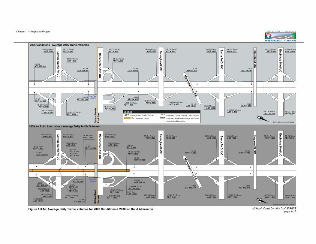
Lomas Santa Fe U
C
So
lan
a B
each
San
Die
go
Encinitas Blvd U
C
Requeza St O
C
Enci
nita
sSo
lana
Bea
ch
Manchester A
ve UC
Birm
ing
ham
Dr O
C
Mackinnon Ave OC
Santa Fe Dr U
C
San ElijoLagoon
I-5 SBADT 155,850
I-5 SBADT 150,050
I-5 NBADT 138,350
I-5 NBADT 133,750
I-5 NB On RampADT 5,400
I-5 NB HOVADT 19,600
HOV InADT 8,100HOV OutADT 1,900
HOV InADT 2,700HOV OutADT 9,200
I-5 SB HOVADT 13,140
I-5 NB HOVADT 19,600
I-5 SB HOVADT 13,140
I-5 SBADT 150,450
I-5 NBADT 144,150
DAR OutADT 33,000
I-5 NB HOV OutADT 22,500
I-5 SB HOV InADT 13,100
DAR InADT 6,540
SB On RampADT 5,400
SB Off RampADT 10,400 SB On Ramp
ADT 6,800SB Off RampADT 5,300
NB Off RampADT 9,600
NB On RampADT 5,800 I-5 NB On Ramp
ADT 5,400
SB On RampADT 6,100
SB Off RampADT 7,300
NB Off RampADT 6,800
I-5 NB On RampADT 7,300
NB Off RampADT 7,000
SB On RampADT 11,250
SB Off RampADT 11,900
NB On RampADT 12,100
NB Off RampADT 11,650
SB On RampADT 4,300
I-5 NB Off RampADT 14,500
I-5 NB Off RampADT 2,400
SB Off RampADT 2,100
I-5 SBADT 148,950
I-5 NBADT 142,750
I-5 SBADT 150,150
I-5 NBADT 143,050
SB On RampADT 14,800
Encinitas Blvd U
C
Enci
nita
sSo
lana
Bea
chSan ElijoLagoon
Manchester A
ve UC
Birm
ing
ham
Dr O
C
Mackinnon Ave OC
Santa Fe Dr U
C
Lomas Santa Fe U
C
So
lan
a B
each
San
Die
go
Requeza St O
C
I-5 SBADT 108,200
I-5 NBADT 106,100
I-5 SBADT 95,900
I-5 NBADT 94,300
I-5 SBADT 94,300
I-5 NBADT 95,300
I-5 SBADT 94,600
I-5 NBADT 95,200
I-5 NB On RampADT 5,000
I-5 NB On RampADT 6,400
I-5 NB On RampADT 1,600
SB On RampADT 5,200
SB Off RampADT 10,500
SB On RampADT 6,100
SB Off RampADT 4,500
NB Off RampADT 8,500
NB Off RampADT 5,400
NB On RampADT 10,200
SB On RampADT 9,400
SB Off RampADT 10,000
NB Off RampADT 10,100
I-5 NB On RampADT 6,500
SB On RampADT 6,000
SB Off RampADT 6,300
NB Off RampADT 6,600NB Off Ramp
ADT 13,400NB On Ramp
ADT 5,300
SB On RampADT 4,000
SB Off RampADT 1,500
SB On RampADT 13,800
I-5 SBADT 106,900
I-5 NBADT 104,300
Schematic View, not to scale
Schematic View, not to scale
LEGENDAverage Daily Traffic VolumesHOV / Managed Lanes
Proposed Construction by Other ProjectsProposed and Existing Bridge StructuresJurisdictional Boundary
ADT
I-5 North Coast Corridor Draft EIR/EISpage 1-15
Chapter 1 – Proposed Project
Figure 1-3.1c: Average Daily Traffic Volumes for 2006 Conditions & 2030 No Build Alternative
2030 No Build Alternative - Average Daily Traffic Volumes
2006 Conditions - Average Daily Traffic Volumes

Carlsbad
Encinitas
Carlsbad
Encinitas
Batiquitos Lagoon
AquaH
ediondaLagoon
Leucadia Blvd O
C
La Costa A
ve OC
Poinsettia Lane OC
Palomar A
irport Rd O
C
Cannon R
d UC
Chinquapin A
ve OC
Tamarack A
ve OC
Carlsbad
Encinitas
Carlsbad
Encinitas
Batiquitos Lagoon
Leucadia Blvd O
C
La Costa A
ve OC
Poinsettia Lane OC
Palomar A
irport Rd O
C
Cannon R
d UC
Chinquapin A
ve OC
Tamarack A
ve OC
AquaH
ediondaLagoon
I-5 SBADT 150,300
I-5 NBADT 142,300
I-5 SBADT 149,400
I-5 NBADT 143,200
I-5 SBADT 146,300
I-5 NBADT 140,600
I-5 SBADT 147,000
I-5 NBADT 143,100
I-5 SBADT 149,200
I-5 NBADT 146,400
I-5 NB On RampADT 9,300
SB On RampADT 9,000
SB Off RampADT 8,500
NB Off RampADT 10,500
I-5 NB On RampADT 9,700
SB On RampADT 10,500
SB Off RampADT 9,600
NB Off RampADT 8,800
I-5 NB On RampADT 7,800
SB On RampADT 10,600
SB Off RampADT 7,500
NB Off RampADT 10,400
I-5 NB On RampADT 12,800
SB On RampADT 9,800
SB Off RampADT 12,000
NB Off RampADT 9,500
I-5 NB On RampADT 26,500
SB On RampADT 3,750
SB Off RampADT 23,700
SB On RampADT 19,250
NB Off RampADT 24,000
I-5 SBADT 150,800
I-5 NBADT 143,500
NB On RampADT 8,600
SB On RampADT 9,000
SB Off RampADT 7,800
SB On RampADT 8,500
SB Off RampADT 7,800
I-5 SBADT 95,200
I-5 NBADT 95,300
I-5 SBADT 94,000
I-5 NBADT 94,100
I-5 SBADT 93,300
I-5 NBADT 92,100
I-5 NBADT 89,000
NB Off RampADT 9,800
NB On RampADT 8,400
SB On RampADT 8,400
SB Off RampADT 6,800
I-5 SBADT 91,700
I-5 NBADT 93,500
I-5 SBADT 95,000
I-5 NBADT 99,100
I-5 SBADT 100,600
NB Off RampADT 10,400
NB On RampADT 6,900
NB Off RampADT 10,000
SB On RampADT 4,600
SB Off RampADT 10,200
NB On RampADT 10,600
NB Off RampADT 5,000
SB On RampADT 2,200
SB Off RampADT 19,500
SB On RampADT 14,000
NB On RampADT 21,500
NB Off RampADT 17,000
Schematic View, not to scale
Schematic View, not to scale
LEGENDAverage Daily Traffic VolumesHOV / Managed Lanes
Proposed Construction by Other ProjectsProposed and Existing Bridge StructuresJurisdictional Boundary
ADT
I-5 North Coast Corridor Draft EIR/EISpage 1-16
Chapter 1 – Proposed Project
Figure 1.3-1d: Average Daily Traffic Volumes for 2006 Conditions & 2030 No Build Alternative
2030 No Build Alternative - Average Daily Traffic Volumes
2006 Conditions - Average Daily Traffic Volumes

Chinquapin A
ve OC
Tamarack A
ve OC
Chestnut A
ve UC
Chinquapin A
ve OC
Tamarack A
ve OC
Chestnut A
ve UC
Buena Vista Creek
Carls
badO
cean
side
Carlsbad Village D
r UC
(Elm A
ve)
Las Flores Dr O
C
Jefferson St OC
SR-78 / I-5 Sep
Cassidy St O
C
California St O
C
Buena Vista Creek
Carlsb
adOce
ansid
e
Carlsbad Village D
r UC
(Elm A
ve)
Las Flores Dr O
C
Jefferson St OC
SR-78 / I-5 Sep
Cassidy St O
C
California St O
CI-5 SBADT 147,600
I-5 NBADT 144,600
I-5 SBADT 147,500
I-5 NBADT 144,700
I-5 SBADT 150,600
I-5 NBADT 147,700
I-5 SBADT 149,500
I-5 NBADT 149,500
I-5 NB On RampADT 7,300
SB On RampADT 9,200
SB Off RampADT 7,600
NB Off RampADT 9,100
I-5 NB On RampADT 9,200
SB On RampADT 9,200
SB Off RampADT 9,100
NB Off RampADT 9,100
I-5 NB On RampADT 5,900
SB On RampADT 2,700
SB Off RampADT 5,800
SB On RampADT 3,900
SB Off RampADT 400 SB On Ramp
ADT 4,700SB Off RampADT 2,100
WB SR-78 toSB I-5 On RampADT 32,500
NB Off RampADT 2,900
I-5 NB On RampADT 37,800
I-5 NB Off RampADT 4,000
NB Off RampADT 32,400
NB On RampADT 400
SB I-5 to EB SR-78 On RampADT 37,500
I-5 NBADT 96,500
I-5 SBADT 98,100
I-5 NBADT 95,900
I-5 SBADT 97,500
I-5 NBADT 98,200
I-5 NBADT 94,600
I-5 SBADT 99,300
I-5 SBADT 96,300
SB On RampADT 8,000
SB Off RampADT 5,500
SB On RampADT 8,200
SB Off RampADT 7,600
NB On RampADT 5,800
NB Off RampADT 8,400
NB On RampADT 7,800
NB Off RampADT 8,400
SB On RampADT 2,600
SB Off RampADT 4,400
SB On RampADT 4,100
SB Off RampADT 2,100
NB On RampADT 4,800
NB Off RampADT 2,500
WB 78 to I-5 SBOn Ramp
ADT 29,000
I-5 SB Off Rampto EB SR-78ADT 30,500
SR-78 WB to I-5 NB On RampADT 31,000
I-5 NB Off Rampto SR-78 EBADT 32,000
I-5 NB Off Rampto SR-78 WBADT 3,000
SR-78 EBto I-5 NB
On RampADT 400
Schematic View, not to scale
Schematic View, not to scale
LEGENDAverage Daily Traffic VolumesHOV / Managed Lanes
Proposed Construction by Other ProjectsProposed and Existing Bridge StructuresJurisdictional Boundary
ADT
I-5 North Coast Corridor Draft EIR/EISpage 1-17
Chapter 1 – Proposed Project
Figure 1-3.1e: Average Daily Traffic Volumes for 2006 Conditions & 2030 No Build Alternative
2030 No Build Alternative - Average Daily Traffic Volumes
2006 Conditions - Average Daily Traffic Volumes

SDN
R
Loma
AltaC
reekLom
aAltaC
reek
California St O
C
Oceanside B
lvd OH
Brooks St O
C
San LuisR
ey River
San LuisR
ey River
Cam
p Pendleton
Oce
ansi
de
U. S
. Mar
ine
Cor
psC
amp
Pend
leto
n
Mission A
ve OC
Neptune W
ay / 8th St OC
Fourth St / Bush St
I-5/SR76 U
C
Cam
p Pendleton UC
Harbor D
rive
Cam
p Del M
ar OC
SDN
R
California St O
C
Oceanside B
lvd OH
Brooks St O
C
Cam
p Pendleton
Oce
ansi
de
U. S
. Mar
ine
Cor
psC
amp
Pend
leto
n
Mission A
ve OC
Neptune W
ay / 8th St OC
Fourth St / Bush St
I-5/SR76 U
C
Cam
p Pendleton UC
Harbor D
rive
Cam
p Del M
ar OC
I-5 SBADT 149,500
I-5 NBADT 151,700
I-5 SBADT 141,500
I-5 NBADT 143,800
I-5 SBADT 122,500
I-5 NBADT 124,000
I-5 SBADT 115,300
I-5 NBADT 114,100
I-5 SBADT 100,500
I-5 NBADT 97,600
NB On RampADT 2,200
NB On RampADT 6,500
NB Off RampADT 14,400 NB On Ramp
ADT 5,000 NB On RampADT 17,000
NB On RampADT 4,000
NB Off Rampto SR-76
ADT 26,900
NB Off RampADT 24,800
SB On RampADT 6,000
SB Off RampADT 14,000
SB On RampADT 11,800
SB Off RampADT 4,800
SB On RampADT 26,100
SB Off RampADT 3,300
SB Off RampADT 3,900
SB On RampADT 18,700
I-5 SB Off Rampto EB SR-76 ADT 15,600SB On Ramp
ADT 12,000
NB Off RampADT 16,700
NB Off RampADT 3,800
I-5 NBADT 95,600
I-5 SBADT 89,300
I-5 NBADT 76,600
NB Off RampADT 14,000
I-5 SBADT 72,200
I-5 NBADT 62,600
I-5 SBADT 60,000
I-5 NBADT 96,600
I-5 SBADT 96,300
I-5 NBADT 80,100
I-5 SBADT 76,700
I-5 SB Off Rampto SR-76 EBADT 9,000
SB On RampADT 12,500
SB Off RampADT 5,500
SB Off RampADT 2,000SB On Ramp
ADT 6,600SB On RampADT 15,500
SB On RampADT 10,000
SB Off RampADT 4,000
SB On RampADT 15,400
SB Off RampADT 3,200
NB Off RampADT 13,500
NB On RampADT 2,000 I-5 NB Off Ramp
to Mission AveADT 20,000
to EBMission AveADT 12,000
NB On RampADT 12,500
to WBMission AveADT 8,000
NB On RampADT 4,500
NB Off Rampto WB Harbor Dr.ADT 3,000
NB On RampADT 3,000
NB Off Rampto SR-76 EBADT 16,500
NB On RampADT 13,000
Gate
Gate
I-5 North Coast Corridor Draft EIR/EISpage 1-18
Chapter 1 – Proposed Project
Schematic View, not to scale
Schematic View, not to scale
LEGENDAverage Daily Traffic VolumesHOV / Managed Lanes
Proposed Construction by Other ProjectsProposed and Existing Bridge StructuresJurisdictional Boundary
ADT
Figure 1-3.1f: Average Daily Traffic Volumes for 2006 Conditions & 2030 No Build Alternative
2006 Conditions - Average Daily Traffic Volumes
2030 No Build Alternative - Average Daily Traffic Volumes

88058
La J
olla
Vill
age
Dr.
Voig
t St.
DA
R
Gen
esee
St.
Roselle St.
SB On RampADT 11,000
NB On RampADT 11,500
NB On RampADT 6,500
NB Off RampADT 20,000
SB On RampADT 8,500
SB Off RampADT 18,000
I-5 SBADT 119,890
I-5 SB HOVADT 19,550
I-5 NB HOVADT 19,500
DAR SB On RampADT 3,700
DAR NB Off RampADT 3,950
I-5 NB HOV Off RampADT 6,800
DAR NB On RampADT 3,650
DAR SB Off RampADT 3,600
I-5 SB HOVADT 12,950 I-5 SB HOV
ADT 28,450
I-5 NB HOVADT 28,900
I-5 SB Bypassto GenesseOff RampADT 15,000
Roselle St.to Genesse Ave.ADT 8,500
Roselle St.I-5 SB On Ramp
ADT 18,500I-5 SBADT 56,890
I-5 SBADT 107,340
I-5 SB Bypassto I-5 SBADT 46,500
I-805 SB BypassADT 38,260
I-5 SB BypassADT 84,760
I-5 SB HOVADT 12,950
Genesse NB Off Rampto Roselle St.
ADT 8,000
I-5 NBOff Ramp
to Roselle StADT 18,000
Roselle StNB Off RampADT 26,000
I-5 NBADT 44,800
I-5 NB HOVADT 15,400
I-5 NB HOVADT 15,400
I-805 NB to I-5 NBADT 48,000
I-5 NB to I-805 NBCombined BypassADT 92,000
Combined I-5 NBand I-805 NBADT 92,800
I-5 NB ADT 44,800
I-5 NBADT 107,000
I-5 NBADT 113,800
I-5 NBADT 94,800
SB On RampADT 19,500
I-5 SBADT 126,390
SB Off RampADT 23,500
NB Off RampADT 19,000 NB Bypass
ADT 22,000
I-5 SBADT 106,890
I-5 SBADT 88,390
NB On Rampto Bypass
ADT 14,000
I-5 NB toI-5 NB BypassADT 32,000
I-5 NB BypassADT 46,000
I-805 SBADT 50,450
Carmel M
tn Rd
5
5
88058
La J
olla
Vill
age
Dr.
Voig
t St.
DA
R
Gen
esee
St.
Roselle St.
SB On RampADT 11,000
NB On RampADT 11,400
NB On RampADT 6,500
NB Off RampADT 20,000
SB On RampADT 8,500
SB Off RampADT 18,000
DAR SB On RampADT 3,700
DAR NB Off RampADT 3,950
DAR NB On RampADT 3,650
Roselle St.to Genesse Ave.
ADT 8,500 I-5 SB BypasstoI-5 SBADT 38,124
Roselle St.I-5 SB On Ramp
ADT 18,500
Genesse NB Off Rampto Roselle St.
ADT 8,000
I-5 NBOff Ramp
to Roselle StADT 18,000 Roselle St
NB Off RampADT 26,000
I-805 NB to I-5 NBADT 47,900
I-5 NB to I-805 NBCombined BypassADT 92,000
NB Off RampADT 19,000 NB Bypass
ADT 22,000
NB On Rampto Bypass
ADT 14,000
I-5 NB BypassADT 46,000
I-805 NB HOVADT 16,200
Carmel M
tn Rd
5
5
I-5 SBADT 108,300
SB HOVADT 24,150
I-5 NB HOVADT 22,500
NB HOVOff Ramp
ADT 6,800
DAR SB Off RampADT 3,600
I-5 SB HOVADT 17,550 I-5 SB HOV
ADT 32,950
I-5 NB HOVADT 31,900
I-5 SB Bypassto GenesseOff RampADT 14,900
I-5 SBADT 53,024
I-5 SBADT 104,800I-5 SB Bypass
to I-5 SBADT 38,124
I-805 SB Bypass
I-5 SB BypassADT 78,000
I-805 SB HOVADT 15,400
I-5 NBADT 38,200
I-5 NB HOVADT 15,700
I-5 NB HOVADT 31,900
ADT 24,976
I-805 NB to I-5 NBADT 47,900
ADT 86,100
Combined I-5 NBand I-805 NB
I-5 NB ADT 38,200
I-5 NBADT 100,400
I-5 NBADT 107,200
I-5 NBADT 88,200
SB On RampADT 19,400
I-5 SBADT 114,800
SB Off RampADT 23,400
I-5 SBADT 95,400
I-5 SBADT 76,900
I-5 NB toI-5 NB Bypass
ADT 32,000 I-805 NB BypassADT 46,000
I-805 SBADT 66,024
SB HOV On RampADT 6,500
Schematic View, not to scale
Schematic View, not to scale
LEGENDAverage Daily Traffic VolumesHOV / Managed LanesProposed DAR (Direct Access Ramp)
Proposed Construction by Other ProjectsProposed and Existing Bridge StructuresJurisdictional Boundary
ADT
I-5 North Coast Corridor Draft EIR/EISpage 1-19
Chapter 1 – Proposed Project
Figure 1-3.2a Average Daily Traffic Volumes for 2030 8+4 Alternatives and 10+4 Alternatives
2030 8+4 Alternatives - Average Daily Traffic Volumes
2030 10+4 Alternatives - Average Daily Traffic Volumes

Carm
el Valley Rd. U
C
Lomas Santa Fe U
C
So
lan
a B
each
San
Die
go
Del M
ar Heights R
d.OC
Via De La Valle U
C
San Die
guito
Riv
er
Carm
el Mtn. R
d.
SB HOVADT 28,450
NB HOVADT 28,900
I-5 SBADT 107,340 I-5 SB
ADT 97,840
I-5 SBADT 160,600I-5 SB
ADT 152,600
I-5 NBADT 156,100I-5 NB
ADT 157,600
I-5 NBADT 82,100
SB HOVADT 24,450
NB HOVADT 25,600
I-5 SB BypassADT 82,760
I-5 SB BypassADT 37,760
SR-56 WBto I-5 SB
ADT 45,000
I-5 NB ADT 92,800
I-5 NB Bypass ADT 90,000
I-5 NB BypassADT 46,000
I-5 NB BypassSR-56 EB
ADT 44,000
NB Off RampADT 14,000
I-5 SBADT 155,600
I-5 NBADT 148,600
SB On RampADT 10,000
NB On RampADT 29,500
NB On RampADT 18,500
NB On RampADT 7,000
SB HOVADT 24,450
NB HOVADT 25,600
SB HOVADT 24,450
NB HOVADT 25,600
NB HOV OffADT 6,000
NB HOV OnADT 2,700
SB HOV OffADT 1,000
SB HOV OnADT 5,000
SB On RampADT 14,000
SB On RampADT 13,500
SB On RampADT 11,000
SB On RampADT 11,000SB Off Ramp
ADT 12,000
SB Off RampADT 28,000
SB Off RampADT 18,000
SB Off RampADT 14,000
NB Off RampADT 14,000 NB Off Ramp
ADT 20,000NB Off RampADT 21,000
NB On RampADT 6,500
NB On RampADT 12,000
I-5 SBADT 142,600
I-5 SBADT 163,600
I-5 NBADT 157,600
SB On RampADT 8,000
Carm
el Valley Rd. U
C
Lomas Santa Fe U
C
So
lan
a B
each
San
Die
go
Del M
ar Heights R
d.OC
Via De La Valle U
C
Car
mel
Valle
yC
reek
Car
mel
Valle
yC
reek
Carm
el Mtn. R
d.
San Die
guito
Riv
er
SB HOVADT 32,950
NB HOVADT 31,900
I-5 SBADT 104,800
I-5 SBADT 94,600
I-5 SBADT 149,600
I-5 SBADT 142,600
I-5 NBADT 148,400
I-5 NBADT 130,400
I-5 NBADT 75,400
SB HOVADT 29,150
NB HOVADT 28,600
I-5 SB BypassADT 76,000
I-5 SB BypassADT 31,000
SR-56 WBto I-5 SB
ADT 45,000
I-5 NB ADT 86,100
I-5 NB Bypass ADT 90,000
I-5 NB BypassADT 46,000
I-5 NB BypassSR-56 EB
ADT 44,000
NB Off RampADT 14,000
I-5 SBADT 143,700
I-5 NBADT 141,500
SB On RampADT 10,000
I-5 SBADT 153,600
I-5 NBADT 150,400
NB On RampADT 29,000
NB On RampADT 18,000
NB On RampADT 6,900
SB HOVADT 29,150
NB HOVADT 28,600
SB HOVADT 29,150
NB HOVADT 28,600
NB HOV OffADT 6,000
NB HOV OnADT 2,700
SB HOV OffADT 1,200
SB HOV OnADT 5,000
SB On RampADT 14,000
SB On RampADT 14,000
SB On RampADT 11,000
SB On RampADT 11,000
SB Off RampADT 12,000
SB Off RampADT 28,000
SB Off RampADT 17,000
SB Off RampADT 13,000
SB On RampADT 7,900
NB Off RampADT 14,000 NB Off Ramp
ADT 20,000NB Off RampADT 20,000
NB On RampADT 6,200
NB On RampADT 12,000
I-5 SBADT 132,600
Schematic View, not to scale
Schematic View, not to scale
LEGENDAverage Daily Traffic VolumesHOV / Managed LanesProposed DAR (Direct Access Ramp)
Proposed Construction by Other ProjectsProposed and Existing Bridge StructuresJurisdictional Boundary
ADT
56
56I-5 North Coast Corridor Draft EIR/EIS
page 1-20
Chapter 1 – Proposed Project
2030 8+4 Alternatives - Average Daily Traffic Volumes
2030 10+4 Alternatives - Average Daily Traffic Volumes
Figure 1-3.2b: Average Daily Traffic Volumes for 2030 8+4 Alternatives and 10+4 Alternatives

5 + 1Aux
5 + 1Aux
Enci
nita
sSo
lana
Bea
ch
DA
R
San ElijoLagoon
San
Elijo
Lago
on
10+4 Alternative Year 2030
I-5 SBADT 155,600
NB HOV OnADT 7,200NB HOV Off
ADT 1,700I-5 NBADT 148,600
NB HOV Off ADT 3,300
NB HOV On ADT 2,200
NB On RampADT 5,500
I-5 NBADT 145,400
NB On RampADT 6,600
NB On RampADT 7,800
NB Off RampADT 15,400
NB On RampADT 2,000
DAR NBOn RampADT 500
DAR NBOff RampADT 3,100
DAR SBOn Ramp
ADT 2,400
DAR SBOff RampADT 400
SB HOVADT 24,450
NB HOVADT 25,600
SB HOVADT 28,750
NB HOVADT 31,100
NB HOVADT 28,500
NB HOVADT 28,500
I-5 NBADT 132,000
I-5 NBADT 131,700
NB HOVADT 27,400
I-5 NBADT 133,100
I-5 SBADT 152,800 SB HOV
ADT 26,750
I-5 SBADT 139,000
SB HOVADT 26,750
I-5 SBADT 138,700
SB HOVADT 24,250
I-5 SBADT 142,100
SB HOV OffADT 6,100
SB HOV OnADT 1,800
SB On RampADT 5,400
SB On RampADT 6,800
SB Off RampADT 11,500
SB Off RampADT 6,500
SB On RampADT 6,800
SB Off RampADT 7,700
SB On RampADT 13,000
SB Off RampADT 13,000
NB Off RampADT 9,700
NB On RampADT 6,500
NB Off RampADT 6,900
NB On RampADT 13,200
NB Off RampADT 13,200
NB Off RampADT 7,500
SB On RampADT 4,600
SB Off RampADT 1,800
SB On RampADT 15,600 SB HOV Off
ADT 2,300
SB HOV On ADT 4,800
5 + 1Aux
5 + 1Aux
Enci
nita
sSo
lana
Bea
chSa
n El
ijoLa
goon
DA
R
San ElijoLagoon
I-5 SBADT 143,700
I-5 NB HOV OnADT 7,200
I-5 NB HOV Off ADT 1,700
I-5 NBADT 141,500
NB HOV Off ADT 3,300
NB HOV On ADT 2,200
I-5 NB On RampADT 5,400
I-5 NBADT 136,900
NB On RampADT 6,200
NB On RampADT 7,400
NB Off RampADT 15,000
NB On RampADT 1,800
DAR NBOn RampADT 500
DAR NBOff RampADT 3,100
DAR SBOn Ramp
ADT 2,400
DAR SBOff RampADT 400I-5 SB HOV
ADT 29,150
I-5 NB HOVADT 28,600
I-5 SB HOVADT 34,250
I-5 NB HOVADT 35,200
NB HOVADT 32,600
NB HOVADT 32,600
I-5 NBADT 123,700
I-5 NBADT 123,200
NB HOVADT 31,500
I-5 NBADT 124,400
I-5 SBADT 139,600 SB HOV
ADT 32,250
I-5 SBADT 126,300
SB HOVADT 32,250
I-5 SBADT 125,900
SB HOVADT 29,250
I-5 SBADT 129,700
I-5 SB HOV OffADT 6,100
I-5 SB HOV OnADT 1,800
SB On RampADT 5,400
SB On RampADT 6,500SB Off Ramp
ADT 10,800
SB Off RampADT 6,100
SB On RampADT 6,600
SB Off RampADT 7,400 SB On Ramp
ADT 12,300SB Off RampADT 12,500
NB Off RampADT 9,700
NB On RampADT 6,300
NB Off RampADT 6,700
NB On RampADT 12,700
NB Off RampADT 12,600
NB Off RampADT 7,300
SB On RampADT 4,400
SB Off RampADT 1,700
SB On RampADT 15,000
SB HOV Off ADT 2,300
SB HOV On ADT 4,800
Schematic View, not to scale
Schematic View, not to scale
LEGENDAverage Daily Traffic VolumesHOV / Managed LanesProposed DAR (Direct Access Ramp)
Proposed Construction by Other ProjectsProposed and Existing Bridge StructuresJurisdictional Boundary
ADT
I-5 North Coast Corridor Draft EIR/EIS page 1-21
Chapter 1 – Proposed Project
Figure 1-3.2c: Average Daily Traffic Volumes for 2030 8+4 Alternatives and 10+4 Alternatives
2030 10+4 Alternatives - Average Daily Traffic Volumes
2030 8+4 Alternatives - Average Daily Traffic Volumes

Carlsbad
Encinitas
Carlsbad
Encinitas
Batiquitos Lagoon
AquaH
ediondaLagoon
Chinquapin A
ve OC
DA
R
I-5 SBADT 142,100
I-5 NBADT 133,100
NB On RampADT 11,500
I-5 NBADT 130,700
NB On RampADT 11,100
NB HOV OffADT 5,800
NB HOV OnADT 3,900
NB HOV Off ADT 5,900
NB HOV OnADT 5,200
SB HOVADT 24,250
NB HOVADT 27,400
SB HOVADT 24,250
NB HOVADT 27,400
I-5 NBADT 132,100
I-5 NBADT 130,100
NB HOVADT 25,500
NB HOVADT 25,500
NB HOV OnADT 4,300
NB HOVADT 25,500
NB HOVADT 25,500
I-5 SBADT 140,200
SB HOVADT 24,950
SB HOVADT 24,950
I-5 SBADT 138,500
I-5 SBADT 135,900
SB On RampADT 13,900
SB Off RampADT 12,000
SB On RampADT 12,000
SB Off RampADT 11,000
SB On RampADT 12,500
SB Off RampADT 9,900
SB On RampADT 4,000
SB Off RampADT 26,000
SB On RampADT 9,000
SB Off RampADT 12,500
SB On RampADT 21,000
NB Off RampADT 13,900
NB Off RampADT 11,600
NB On RampADT 10,000
NB Off RampADT 12,000
NB On RampADT 27,300
NB Off RampADT 24,400
NB On RampADT 11,900
NB HOV OffADT 4,000
NB Off RampADT 8,800
I-5 NBADT 132,600
I-5 NBADT 133,000
NB HOVADT 25,500
SB HOVADT 24,950
I-5 SBADT 136,900
SB HOVADT 24,950
I-5 NBADT 135,800
I-5 SBADT 140,400
SB DAROn RampADT 2,550
SB DAROff RampADT 3,200
NB DAROff RampADT 2,500
NB DAROn RampADT 3,100
CarlsbadEncinitas
Carlsbad
Encinitas
Batiquitos Lagoon
AquaH
ediondaLagoon
Chinquapin A
ve OC
DA
R
I-5 SBADT 129,900
I-5 NBADT 124,500
NB On RampADT 10,500
I-5 NBADT 122,200
NB On RampADT 10,700
NB HOV OnADT 4,700
NB HOV OffADT 7,000
NB HOV Off ADT 7,000
NB HOV OnADT 6,200
SB HOVADT 29,250
NB HOVADT 31,500
SB HOVADT 29,250
NB HOVADT 31,500
I-5 NBADT 124,600
I-5 NBADT 122,500B HOV
ADT 29,200
NB HOV OnADT 5,100
NB HOVADT 29,200
I-5 SBADT 128,700
SB HOVADT 30,050
SB HOVADT 30,050
I-5 SBADT 127,700
I-5 SBADT 125,000
SB On RampADT 12,000
SB Off RampADT 10,800
SB On RampADT 11,000
SB Off RampADT 10,800
SB On RampADT 11,700
SB Off RampADT 9,000
SB On RampADT 3,900
SB Off RampADT 25,000
SB On RampADT 8,100
SB Off RampADT 12,300
SB On RampADT 20,500
NB Off RampADT 12,800
NB Off RampADT 10,600
NB On RampADT 9,100
NB Off RampADT 11,200
I-5 NB On RampADT 26,800
NB Off RampADT 24,300
NB On RampADT 11,700
NB HOV OffADT 4,800
NB Off RampADT 7,800
I-5 NBADT 125,000
I-5 NB HOVADT 29,200
I-5 SB HOVADT 30,050
I-5 SBADT 125,600
SB HOVADT 30,750
I-5 NBADT 128,600
I-5 SBADT 129,800
SB DAROn RampADT 3,100
SB DAROff RampADT 3,800
NB DAROff RampADT 3,100
NB DAROn RampADT 3,700
Schematic View, not to scale
Schematic View, not to scale
LEGENDAverage Daily Traffic VolumesHOV / Managed LanesProposed DAR (Direct Access Ramp)
Proposed Construction by Other ProjectsProposed and Existing Bridge StructuresJurisdictional Boundary
ADT
I-5 North Coast Corridor Draft EIR/EISpage 1-22
Chapter 1 – Proposed Project
Figure 1-3.2d: Average Daily Traffic Volumes for 2030 8+4 Alternatives and 10+4 Alternatives
2030 10+4 Alternatives - Average Daily Traffic Volumes
2030 8+4 Alternatives - Average Daily Traffic Volumes

Carlsb
adOce
ansid
e
Buena Vista Creek
California St O
C
SB On RampADT 9,800
SB On RampADT 10,500
SB On RampADT 3,900SB Off Ramp
ADT 7,800
SB Off RampADT 9,200
SB Off RampADT 6,000
SB On RampADT 4,800
SB Off RampADT 2,200
SR-78 to I-5 SBADT 41,000
I-5 SB to SR-78ADT 39,500
I-5 SBADT 137,500
I-5 SBADT 134,900
NB On RampADT 7,900
NB Off RampADT 9,900
I-5 NB On RampADT 9,400
NB Off RampADT 10,000
NB On RampADT 6,200 I-5 NB to SR-78 WB
ADT 4,500
SR-78 WB to I-5 NBADT 38,200
I-5 NBADT 133,300
NB HOVADT 25,200
NB Off RampADT 3,800
I-5 SBADT 140,400
I-5 NBADT 135,800
SB HOVADT 25,600
NB HOVADT 26,400
I-5 NBADT 133,800
NB HOVADT 26,400
SB HOVADT 25,800
I-5 SBADT 138,200
NB HOVADT 26,400
SB HOVADT 25,800
I-5 SBADT 136,900
I-5 SBADT 139,000
I-5 NBADT 133,200
I-5 NBADT 135,600
I-5 NB to SR-78 EB ADT 36,500
NB HOVADT 26,400
SB HOVADT 25,800
Carlsb
adOce
ansid
e
Buena Vista Creek
California St O
C
SB On RampADT 9,500
SB On RampADT 9,500
SB On RampADT 3,700
SB Off RampADT 7,700
SB Off RampADT 9,100
SB Off RampADT 5,900
SB On RampADT 4,700
SB Off RampADT 2,200
SR-78 to I-5 SBADT 38,800
I-5 SB to SR-78ADT 500
I-5 SBADT 129,800
I-5 SBADT 127,300
NB On RampADT 7,800
NB Off RampADT 9,600
NB On RampADT 9,300NB Off Ramp
ADT 9,300
NB On RampADT 6,100
I-5 NB to SR-78 WBADT 4,300
I-5 NBADT 128,700
SR-78 EB to I-5 NBADT 38,400
I-5 NBADT 128,700
NB HOVADT 28,700
SR-78 EB to I-5 NBADT 38,400
NB Off RampADT 3,700
I-5 SBADT 129,800
I-5 NBADT 128,600
SB HOVADT 30,750
SB HOV OnADT 5,000
SB HOV OffADT 5,200
NB HOVADT 30,100
I-5 NBADT 126,800
NB HOVADT 30,100
SB HOVADT 30,950
I-5 SBADT 127,800
NB HOVADT 30,100
SB HOVADT 30,950
I-5 SBADT 127,400
I-5 SBADT 129,600
I-5 NBADT 126,800
I-5 NBADT 129,200
I-5 NB to SR-78 EB ADT 34,600
NB HOVADT 30,100
SB HOVADT 30,950
Schematic View, not to scale
Schematic View, not to scale
LEGENDAverage Daily Traffic VolumesHOV / Managed LanesProposed DAR (Direct Access Ramp)
Proposed Construction by Other ProjectsProposed and Existing Bridge StructuresJurisdictional Boundary
ADT
I-5 North Coast Corridor Draft EIR/EISpage 1-23
Chapter 1 – Proposed Project
Figure 1-3.2e: Average Daily Traffic Volumes for 2030 8+4 Alternatives and 10+4 Alternatives
2030 10+4 Alternatives - Average Daily Traffic Volumes
2030 8+4 Alternatives - Average Daily Traffic Volumes

SDN
R
San Luis R
ey River
Cam
p Pendleton
Lom
aAl
taC
reek
Cassidy
StOC
Mission A
ve OC
Fourth St / Bush St
DA
R
Vandergrift Blvd
SB Off RampADT 6,500
SB On RampADT 16,000
SB Off RampADT 5,000 I-5 SB Off Ramp
to SR-76 WBADT 3,300
NB On RampADT 2,300
NB Off RampADT 15,000
NB On RampADT 6,600
SB HOVADT 24,750
I-5 NBADT 135,600
NB HOVADT 25,200
SB HOVADT 23,600
I-5 SBADT 125,400
SB DAR On Ramp ADT 1,950
SB DAR Off Ramp ADT 800
NB DAR On Ramp ADT 900
NB DAROff Ramp
ADT 2,100
SB HOV OnADT 5,600
SB HOV Off ADT 1,000
I-5 SBADT 110,000
SB HOVADT 19,000
NB HOVADT 19,200
NB HOVADT 19,200
I-5 SBADT 101,500
I-5 SBADT 105,500
SB HOVADT 19,000
SB On RampADT 25,000
SR-76 toI-5 SB On Ramp
ADT 27,500
SB On RampADT 19,000
SB Off RampADT 4,000
SR-76 EBI-5 SB Off Ramp
ADT 15,700
I-5 NBADT 132,000
NB On RampADT 5,000 NB On Ramp
ADT 4,000
NB Off RampADT 26,000
I-5 NB Off Rampto SR-76
ADT 27,000
SR-76 toI-5 NB On Ramp
ADT 19,000NB HOV
ADT 19,200I-5 NBADT 111,000
I-5 NBADT 103,000
I-5 NBADT 104,700
I-5 NB Off Rampto EB Harbor Dr.
ADT 17,500
I-5 NB Off Rampto EB Harbor Dr.ADT 4,000
SDN
R
San Luis R
ey River
Cam
p Pendleton G
ate
Lom
aAl
taC
reek
Cassidy
StOC
Mission A
ve OC
Fourth St / Bush St
DA
R
Vandergrift Blvd
SB Off RampADT 6,300
SB On RampADT 15,000
SB Off RampADT 4,900 SB Off Ramp
to SR-76 WBADT 3,300
NB On RampADT 2,300
NB Off RampADT 14,500
NB On RampADT 6,400
SB HOVADT 29,650
I-5 NBADT 131,000
NB HOVADT 28,700
NB HOV OffADT 6,900
NB HOV OnADT 1,200
SB HOVADT 28,500
SB HOVADT 23,000
I-5 SBADT 118,600
I-5 SBADT 127,300
SB DAR On Ramp ADT 2,050
SB DAR Off Ramp ADT 900
NB DAR On Ramp ADT 1,000
NB DAROff Ramp
ADT 2,200
SB HOV OnADT 6,700
SB HOV Off ADT 1,200 I-5 SB
ADT 104,800
SB HOVADT 23,000
NB HOVADT 21,800
NB HOVADT 21,800
I-5 SBADT 97,300
I-5 SBADT 105,500
SB HOVADT 23,000
SB HOVADT 23,000
SB On RampADT 24,200
SR-76 toI-5 SB On Ramp
ADT 26,500
SB On RampADT 18,800
SB Off RampADT 4,000
SR-76 EBSB Off RampADT 15,700
I-5 NBADT 128,600
NB On RampADT 5,000
NB On RampADT 4,000
NB Off RampADT 25,200
NB Off Rampto SR-76
ADT 26,300
SR-76 toNB On RampADT 18,700
NB HOVADT 21,800 I-5 NB
ADT 108,400
I-5 NBADT 100,800 I-5 NB
ADT 105,300
NB HOV OffADT 21,800
NB Off Rampto EB Harbor Dr.
ADT 17,300
NB Off Rampto EB Harbor Dr.ADT 4,000
Schematic View, not to scale
Schematic View, not to scale
Gate
I-5 North Coast Corridor Draft EIR/EISpage 1-24
Chapter 1 – Proposed Project
LEGENDAverage Daily Traffic VolumesHOV / Managed LanesProposed DAR (Direct Access Ramp)
Proposed Construction by Other ProjectsProposed and Existing Bridge StructuresJurisdictional Boundary
ADT
Figure 1-3.2f: Average Daily Traffic Volumes for 2030 8+4 Alternatives and 10+4 Alternatives
2030 10+4 Alternatives - Average Daily Traffic Volumes
2030 8+4 Alternatives - Average Daily Traffic Volumes