intersatellite link for earth observation satellites ... · american institute of aeronautics and...
TRANSCRIPT

American Institute of Aeronautics and Astronautics
1
Intersatellite link for Earth Observation Satellites constellation
Pasquale Maurizio De Carlo , Leonardi Roberto , Graziano Marano * and Giuseppe Francesco De Luca † Ministero della Difesa, SGD-DNA – Via XX Settembre 123a, 00100 Roma ITALY
Agenzia Spaziale Italiana -Viale Liegi 26, 00100 Roma ITALY
Michelangelo L’Abbate, Domenico Oricchio, Paolo Venditti ‡ Alcatel Alenia Space – Italia; via Saccomuro 24, 00131 Roma ITALY
and
Maria Rosaria Santovito§ Consortium of Research on Advanced Remote Sensing Systems
Viale J.F. Kennedy 5, 80125 Napoli ITALY
This paper is devoted to investigate the possibility to implement a data Intersatellite Link between satellites of an Earth Observation constellation and a dedicated TLC GEO satellite. An EO system is mainly composed of two segments (space and ground) connected by a complex network of communications that permits to manage the operations of the constellation. Due to the high performances in terms of imaging capabilities of the radar/optical payloads a corresponding high capacity to download data to ground is needed. To guarantee that the system is able to download to the ground station, in a proper time, all the images taken from the radar during the mission, external ground stations, located in a polar zone, have to be foreseen. Polar stations offer a service needed to provide the requested images to the users in a near real-time manner. In this paper an alternative approach, using an Intersatellite link system (ISLs) instead of polar stations, is presented. The most relevant trade-offs from technical point of view have been addressed. The purposes of this activities is to demonstrate the capability of a high speed two way optical link, between LEO and GEO terminals, with a bit rate in the order to 2.5 Gbps in the frame of satellites constellation. This implementation should permit to avoid the use of polar stations ensuring in the same time the achievement of high system time performances, in an operational cost–saving approach.
I. Introduction arth Observation Systems based on a constellation of two or more low orbiting satellites equipped with SAR (Synthetic Aperture Radar) and/or High Resolution Optical instruments, are required to be designed for high
performance operations in terms of fast revisit time and very short system response time.
* Ministero della Difesa, SGD-DNA – Via XX Settembre 123a, 00100 Roma ITALY. † Agenzia Spaziale Italiana -Viale Liegi 26, 00100 Roma ITALY . ‡ Alcatel Alenia Space – Italia; via Saccomuro 24, 00131 Roma ITALY . § Consortium of Research on Advanced Remote Sensing System, Viale J.F. Kennedy 5, 80125 Napoli ITALY .
E
American Institute of Aeronautics and Astronautics
2
An Earth Observation System is mainly composed of two segments (space and ground) connected by a complex network of communications that permits to manage the operations of the constellation. Due to the high performances in terms of imaging capabilities of the imaging system a corresponding high capacity to download data to ground is needed. To guarantee that the system is able to download to the ground station, in a proper time, all the images taken from the imager (radar and/or optical) during the mission, ground stations, located in a polar zone, have been foreseen. Polar stations offer a service needed to provide the requested images to the users in a near real-time manner. An alternative approach is investigated, taking into consideration an intersatellite link system (ISLs) instead of polar stations, in order to permit highly efficient transmission of data towards ground stations. ISLs permits a satellite to communicate, when it is not visible from a receiving ground station, using a geostationary TLC satellite. In particular, optical intersatellite link (OISLs) will transfer high volume data between the Earth Observation (LEO) satellite and a dedicated TLC GEO satellite. Also an optical feeder space to ground link has been considered
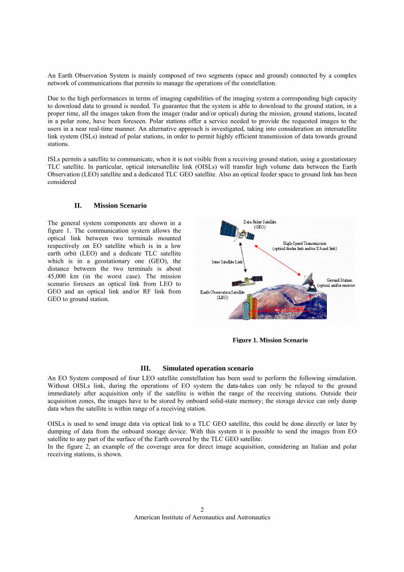
II. Mission Scenario The general system components are shown in a figure 1. The communication system allows the optical link between two terminals mounted respectively on EO satellite which is in a low earth orbit (LEO) and a dedicate TLC satellite which is in a geostationary one (GEO), the distance between the two terminals is about 45,000 km (in the worst case). The mission scenario foresees an optical link from LEO to GEO and an optical link and/or RF link from GEO to ground station.
III. Simulated operation scenario An EO System composed of four LEO satellite constellation has been used to perform the following simulation. Without OISLs link, during the operations of EO system the data-takes can only be relayed to the ground immediately after acquisition only if the satellite is within the range of the receiving stations. Outside their acquisition zones, the images have to be stored by onboard solid-state memory; the storage device can only dump data when the satellite is within range of a receiving station. OISLs is used to send image data via optical link to a TLC GEO satellite, this could be done directly or later by dumping of data from the onboard storage device. With this system it is possible to send the images from EO satellite to any part of the surface of the Earth covered by the TLC GEO satellite. In the figure 2, an example of the coverage area for direct image acquisition, considering an Italian and polar receiving stations, is shown.
Figure 1. Mission Scenario

American Institute of Aeronautics and Astronautics
3
A representative scenario, in terms of data
downlink rate, satellite data receiving facilities (e.g.:located in Italy centre, Fairbanks and Kiruna Polar Stations) availabilities, and capabilities, has been considered. In that context, the following down linked data volume can be considered:
Station Visibility * Data volume ** [s] [Gbit] Italy center 36450 11300 Kiruna 88400 27400 Fairbanks 81120 25150
* 16 days visibility period with one satellite; ** data volume from one satellite
Table 1 – Ground station 16 days contact duration and acquisition capability without OISL
When an OISL is considered between the LEO satellite and a TLC GEO satellite (see figure 3) able to re-transmit the data coming from the LEO satellite towards the ground stations the following amount of data can be considered (assuming the same LEO current data rate from TLC GEO satellite).
Station Visibility * Data volume** [s] [Gbit] Any within the GEO satellite footprint
965500 299300
* 16 days visibility period with one satellite; ** data volume from one satellite
Table 2 – Ground station 16 days contact duration and acquisition capability with OISL
Figure 3 OISL link simulated scenario
Figure 2. Areas for direct image acquisition (example for Italian and Polar stations)
American Institute of Aeronautics and Astronautics
4
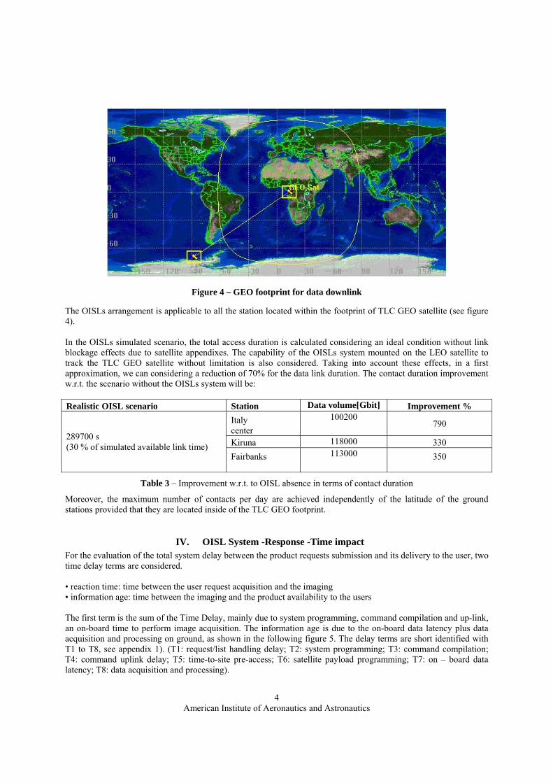
The OISLs arrangement is applicable to all the station located within the footprint of TLC GEO satellite (see figure 4).
In the OISLs simulated scenario, the total access duration is calculated considering an ideal condition without link blockage effects due to satellite appendixes. The capability of the OISLs system mounted on the LEO satellite to track the TLC GEO satellite without limitation is also considered. Taking into account these effects, in a first approximation, we can considering a reduction of 70% for the data link duration. The contact duration improvement w.r.t. the scenario without the OISLs system will be: Realistic OISL scenario Station Data volume[Gbit] Improvement %
Italy center
100200 790
Kiruna 118000 330 289700 s (30 % of simulated available link time)
Fairbanks
113000 350
Table 3 – Improvement w.r.t. to OISL absence in terms of contact duration
Moreover, the maximum number of contacts per day are achieved independently of the latitude of the ground stations provided that they are located inside of the TLC GEO footprint.
IV. OISL System -Response -Time impact For the evaluation of the total system delay between the product requests submission and its delivery to the user, two time delay terms are considered. • reaction time: time between the user request acquisition and the imaging • information age: time between the imaging and the product availability to the users The first term is the sum of the Time Delay, mainly due to system programming, command compilation and up-link, an on-board time to perform image acquisition. The information age is due to the on-board data latency plus data acquisition and processing on ground, as shown in the following figure 5. The delay terms are short identified with T1 to T8, see appendix 1). (T1: request/list handling delay; T2: system programming; T3: command compilation; T4: command uplink delay; T5: time-to-site pre-access; T6: satellite payload programming; T7: on – board data latency; T8: data acquisition and processing).
Figure 4 – GEO footprint for data downlink

American Institute of Aeronautics and Astronautics
5
The proposed configuration presents advantages from the point of view of end-to-end performances, in particular the reduction of uplink and downlink delays. The overall typical operational strategy may be preserved (i.e. synchronous routine modality, asynchronous on demand imaging modality), but the increased ground station visibility window allows: - performing the complete uplink of the mission plan and its activation in one single passage, with consequent
reduction of the command uplink delay time; - reducing the information age delay, in particular the contribution of the On-Board Data Latency and the down-
load at X-band Data Acquisition Station; Payload data latency (T7) is defined as the time interval between image sensing time and related data down-load start time. This time interval is equal (In the worst case) to the max visibility gap for the given receiving stations configuration. As such, this time has been evaluated equal to:
- 11h 30m for National Station only, located in Italy centre; - 1h 19min for Kiruna – Fairbanks ground station scenario In case of using a TLC GEO satellite configuration the maximum visibility gap will be reduced to about half an orbit (i.e. about 45 minutes) As result, - the Maximum information age will be heavily reduced with respect to the values given for the National station
only (i.e. about 45m, against 11h 30min ). - In the scenario with Kiruna-Fairbanks the T7 is one half (about 40min).
Furthermore, since the uplink strategy will not be limited by two daily contact windows with a station located in Italy centre, a trade-off may be carried out to verify if a shift backwards or forward in the overall system chronology brings to an optimisation in terms of acquisitions on the Mediterranean basin and operational costs reduction (e.g. operators shift mainly during day-time).
V. System architecture
The general architecture foresees two optical terminal embarked on the LEO satellite and GEO satellite, respectively. The general OISLs system will function essentially like a conventional RF system. The main components are: a two-axis gimbaled telescope, an optical bench with a fine pointing system, a communication sensor and laser diodes, a thermal control system for precision temperature control. One of the major differences between RF and optical ISLs is the pointing requirements. RF system have pointing accuracy of mrads, while optical one have μRad and/or nRad.
The general system architecture are shown in the figure 6.
Figure 5 – system response time delay decomposition

American Institute of Aeronautics and Astronautics
6
The present proposal is primarily based on an Intersatellite link between LEO to GEO satellites, but high data rate (over 10 Gbps) links between space to ground (optical feeder), although propagation effects due to the atmosphere and weather make this technique a much more difficult, can be also considered.
VI. Technological considerations
To use optical links in satellite communication is attractive because of their ability to provide very high speed communications with data rate on the order of 10 Gbps. The RF link is not able to provide such high data rate even in the millimeter wave region and is difficult to use the frequency bands without any interference. According to the link equation, an optical telescope with an aperture equivalent to that of RF antenna provides tens of db of link efficiency improvement. The distance between a LEO satellite and a GEO satellite could be about 45,000 km and an optical Intersatellite link requires high power laser devices, high gain optical antenna (telescope) and highly sensitivity optical detectors. The beam divergence of the laser is typically about 1 – 2 μRad and its footprint on the Earth surface from a distance of 45,000 km is in the order of tens of meter. Key technologies for a such system are the beam acquisition to acquire an incoming laser beam with an accuracy that permit to initiate a communications link, the beam tracking to receive the incoming laser beam with a high accuracy (better than one μRad) and to maintain the communication link and the beam pointing to transmit the laser beam toward the other satellite and to compensate the relative motion between the two satellite. Typical target specifications for the major onboard components are reported in the following: 1 to 2,5Gbps for 1,55 μm wavelength, 15 to 20 cm telescope aperture, typically 100’s mW (less than 10 W peak power) optical power from laser transmitter, high sensitivity Er-doped fiber amplifier (based on terrestrial fiber optic link). The short emission wavelength allows the use of transmission optics of modest dimension, reducing the mass of the communication subsystems and therefore the mass of the satellite host. As well as reducing the mass, optical systems have the additional benefit of reducing antenna size (diameters typically are less than 30cm) and the power consumption of the communication subsystem, created less disturbance to the satellite compared with larger and heavier RF systems. The narrow beam divergence afford interference-free, low probability of intercept (a very small area exist where interception of transmitted data is possible) and secure operation.
These optical link are important also for military applications [Dreisewerd1, Dreisewerd2]. In short, optical satellite link are important whenever high data rates, long link distances, and low interference are required. The laser communication is a point-to-point communication system. The simplest optical communication system is formed by a transmission and a receiver section with the two terminals perfectly aligned on the ground. The high level block diagram of a typical optical satellite communication payload is showed in Figure 7.
Figure 6 – System architecture
Earth Observation satellite
SAR Payload
OISLs LEOterminal
SAR data stream
TLC GEO satellite
OISLs GEO terminal
Opticallink
GEO data relay
Optical or RF Link to ground

American Institute of Aeronautics and Astronautics
7
The transmission terminal consists of simple modulator which drives the laser source and the telescope; the receiver consists of the optical telescope, the optical sensor device and the demodulator. In the space the satellite optical communication needs Acquisition, Tracking and Pointing subsystem (known as ATP) in order to establish and maintain the optical link. The Acquisition is the phase where the two terminals adjust their line-of-sight in order to receive the transmitter beacon beam of the counter terminal. In the Tracking phase the line of sight of the two terminals is maintained. Because of the low beam divergence (an advantage because of the greater power at the receiver), the spatial tracking for an optical link is more stringent than that of a conventional microwave link. For example, the angular beamwidth is approximately 10μrad compared to several milliradians for microwave link. During the Pointing phase both satellites point toward the position of the counter terminal in order to begin the transmission data. The complexity of pointing system derives from the necessity of satellite to point each other over distance of tens of thousand of kilometers with a beam divergence angle of microradians while the satellites move and vibrate. The development of satellite optical communication is carried out mostly by Europe, Japan and United States [Edelson, Lutz, Suzuki]. More than twenty years of technology endeavours, sponsored by ESA and other European space agencies, has put Europe in a leading position in the domain of space laser communications. The most visible result of this effort is SILEX (Semiconductor Laser Intersatellite Link Experiment), the world's first launch-ready civilian laser communication system. On 30 November 2001, by SILEX, the first-ever transmission of an image by laser link from one satellite to another took place. The system using a pre-operational link between the French SPOT-4 low earth orbit (LEO) satellite and the ESA Advanced Relay and Technology Mission Satellite (ARTEMIS) in geostationary orbit (GEO). The laser diode wavelength range 800-850nm has been used, the best compromise between component maturity and performance in the space. The SILEX design is based on several key component [Fletcher]: - GaAlAs laser diodes of two types: single mode laser diodes of 120mW peak power for communication
channel, and a combination of several high-power (500mW) laser diodes for the bright, divergent, unmodulated beacon used in the link acquisition sequence;
- Silicon charge-coupled devices (CCDs) are the sensors which detect the optical beam angular incidence and
thus maintain submicroradian pointing accuracy. Two types are used: a large field of view (388×388 pixels) sensor is used to detect the partner’s position during the acquisition sequence; a smaller matrix (17×17 pixels) with high-frequency read-out (8 kHz) and processing of the centre four pixel output is used for closed-loop tracking process;
Figure 7: High level block diagram of a terminal for optical satellite communication payload.

American Institute of Aeronautics and Astronautics
8
- Silicon avalanche photodiode (APDs) with highly optimised excess noise factor allow maximum
communication performance with the very low-level received signal (135 photons/bit direct detection at 810nm, BER=10-6 and 60Mbit/s);
It has to be underlined that SILEX “has been dimensioned using the limited laser diode power available at the end of the 1980's, namely 60mW average power at 830nm” [Lutz]. Thus, SILEX appears hardly an attractive alternative to a RF terminal of comparable transmission capability. Nevertheless SILEX programme shows high reliability with a life time higher than 100000 hours [Planche]. The success of SILEX demonstrates also that for low earth and geostationary orbits (LEO & GEO) optical links the semiconductor lasers which can support simple current modulation up to 600Mbp, with wavelength range compatible with silicon detectors, adapted to fast acquisition, high electrical/power efficiency (about 30%), compatibility with multiplexing thanks to available wavelengths, are suitable in order to achieve maximum data rates, channel capacity with relatively high average to peak power ratio [Biswas]. Their main drawbacks are the limited available output power (about 0.4W) for communication transmitter and the diverging astigmatic beam pattern which requires an anamorphoser. For this reason for deep space communications solid state Q-switched lasers with high peak power and low duty cycle, are ideally suited in order to maximise the photon efficiency, to minimize the average to peak power ratios, to hold the average power constant. Hence today the transmitter typically used in a free-space laser communications system are either semiconductor laser diodes, solid state lasers and recently fiber amplifiers/lasers. For free space communication system, the dimension of a terminal are driven by the aperture of the telescope required to collect enough photons to achieve a specified BER at a given data rate, received power and link distance. The sensitivity of the receiver used is, therefore, an essential driven for the telescope size and, hence the terminal dimensions. For an instrument of the size of an optical terminal the mass is quite well related to the dimensions. Taking into account the power consumption, it is also advantageous to select the design that offers the highest receiver sensitivity because the required transmit power is kept lower. Many works [Bondurant, Rochat, Shimer, Chan, Cryan] demonstrate that for a given link distance the sensitivity of a coherent terminal can be used to reduce the telescope size, the overall dimension and the mass of the terminal. Nevertheless the implementation loss (mechanical/thermal stability requirements) for coherent systems and the higher complexity negates theoretical advantage while direct detection in the space is easier and lower risk based on current technology thanks to terrestrial heritage. Going into details, with a suitable low noise optically preamplified direct detection receiver such as an Erbium doped fiber amplifier (EDFA), many of the lost dBs can be recovered. EDFA is used to boost the intensity of optical signals being carried through the fiber optic communication system. The optical fiber is doped with rare earth element erbium so that the glass fiber can absorb light at one frequency and emit light at another frequency. The external semiconductor laser couples light into the fiber at infrared wavelengths of either 980 or 1480nm. This action excites the erbium atoms. Additional optical signals at wavelengths between 1530 and 1620nm enter the fiber and stimulate the excited erbium atoms to emit photons at the same wavelength as the incoming signal. This action amplifies a weak optical signal to higher power. Chan underlines how though EDFA and heterodyne detection have similar performance, the EDFA pre-amplified direct detection receiver lends itself to much easier implementation and has to be favourite for optical satellite communication systems [Chan]. Also for Cryan, owing to of the reduced complexity and good potential sensitivity, direct detection is the preferred technology for optical satellite communications [Cryan]. However about EDFA, most of the commercial available fibers are extremely sensitive to the radiation environment in space: radiation damage can increase the transmission loss significantly and, thus, degrade the fiber amplifier significantly. Due to the complex spectrum of the radiation environment in space and the low dose rate, it is very difficult to perform fully representative space radiation test on ground. Although there are some technological solutions to reduce losses of the fibers in space [Rochat], the fiber amplifiers remain an extremely sensitive devices in space environment.

American Institute of Aeronautics and Astronautics
9
An example of a typical optical transceiver using the described EDFA (has been developed by Kongsberg Defense and Aerospace (Norway)) which main characteristics are reported in table 3.
EDFA optical transceiver
Total mass 2.1kg Volume 2733cm3
Max power consumption 40W Output wavelength 1544.5nm Average output power 3.5dBm @ 2.5Gbit/s modulation BER (Bit Error Rate) 10-5
Input power of PIN detector -20.4dBm with RZ-signals -18.7dBm with NRZ signals
Receiver sensitivity at EDFA input -40dBm @ BER 10-5
Table 3: Main characteristics of EDFA optical transceiver
The main advantages using EDFA technology are: high reliability with a life time higher than 106 hour, high data rate capability (several Gbps), high output power (up to 5W), simple current modulation up to several Gbps, compatibility with multiplexing thanks to wavelength selectable by grating modification. The main drawback is the relative low electrical\optical power efficiency (5 to 10%). Considering the allocated volume of the described transceiver, estimated preliminary enveloping dimensions and weights of the on board control unit, power supply unit, telescope and beacon and APT subsystem reported in table 4.
Subsystem Volume Weight On board control unit 0.018m3 10kg
Power supply unit 0.016m3 10kg Telescope and Beacon 0.064m3 8kg
ATP unit 0.018m3 8kg
Table 4: Preliminary estimated enveloping dimensions and weights of an optical communication subsystem. Figure 8 report preliminary non-redounded optical architecture for EDFA technologies proposed in a recent study [Laurent].
Figure 8: 1.55μm optical terminal architecture. λT and λR are respectively for Transmitted and Received laser wavelength.

American Institute of Aeronautics and Astronautics
10
The transmitter is a DFB laser directly modulated with a doped fiber amplifier. Both these elements are controlled by the communication electronics. A direct detection scheme is selected: the receiver is composed of an optical fiber pre-amplifier coupled to an InGaAs photodiode.
VII. Conclusions
The mission of the OISL system is to support an Earth Observation satellites constellation for telemetry, control (TT&C) and mission data requirements. The purpose of this paper is to investigate the GEO Data Relay Satellite in order to determine whether or not it can support and/or augment the capabilities of space/ground link connectivity. In particular, if it is possible and /or useful to replace the use of polar station with a dedicate TLC GEO satellite. Based upon the results of this study, it can be concluded that the use of a TLC GEO satellite can extremely augment the contacts duration with national stations (e.g.: Italy centre about 800%), with respect a system without OISL system. It should be noted that to address the use of an OISL system, instead of a polar station, is significant and could to be a more cost effective approach to support the implementation of EO satellites constellation.
From the technological point of view, the use of the described architecture appears particularly innovative thanks to the use of 1550 nm wavelength on satellite. Worldwide Space Agencies have developed programs to increase the satellite links data rates and, as shown in a study performed by NASA, the current X-band links are almost saturated and the plan is to use the Ka band and optical links. In conclusion, band saturation and the advantages to obtain more bandwidth with smaller antenna size and radiated electromagnetic power are the main reasons to investigate more and more in this new technical field of space communication.

American Institute of Aeronautics and Astronautics
11
Appendix The first term (Reaction time) is the sum of the Time Delay Terms reported in the following table A1:
Whereas the information age is the sum of the Time Delay Terms reported in the following table A2:
References [Araki] K. Araki et al., “Inter-satellite link by lightwave”, Technical Digest of International Topical
meeting on Microwave Photonics, December 3-5 1996, pp.221-224. [Biswas] A. Biswas, “High data-rate laser transmitters for free-space laser communications”, JPL Technical
report, available at http://lasers.jpl.nasa.gov/PAPERS/HIEFFLSR/ocg00275.pdf [Bondurant] R.S. Bondurant, “High rate space laser communication”, LEOS ’99, San Francisco, CA. [Chan] V.W.S. Chan, “Optical space communication”, IEEE Journal on selected topics in quantum
electronics, vol.6, no.6, Nov/Dec 2000, pp. 959-975. [Cryan] R.A. Cryan, “Space communications employing optical pulse position modulation”, ECSC, 3rd
European Conference on Satellite Communications, November 2-4 1993, pp. 192-195.
Reaction Time delay Term
Short identifier
Description
request/list handling delay T1 It is the time interval between the customer request acceptance at the user ground segment site and the formal submission of associated programming request list to Satellite Control Center
system programming T2 It is the time interval between the formal submission of associated programming request list and the availability of the Mission Plan
command compilation T3 It is the time interval between the availability of the Mission Plan and the availability of the fine schedule at the TT&C station site
command uplink delay T4 It is the time interval between the availability of the fine schedule at the TT&C station site and the up-link completion to the satellite
time-to-site pre-access T5 It is the time interval between the availability of the fine schedule on board and the starting of the satellite operations to perform the image acquisition
satellite payload programming
T6 It is the time interval between the starting of the satellite operations and the payload switching in the required operative mode (i.e. sensing)
Table A1. Reaction Time delay terms
Reaction Time delay Term Short identifier
Description
on – board data latency T1 It is the time interval between the payload switching in operative mode and the relevant data-take down-load completion at x-band data acquisition station site
data acquisition and processing
T2 It is the time interval between the relevant data-take down-load completion at x-band data acquisition station site and the product availability at the user ground segment site. This time includes the time to transfer the data from data acquisition station to processing center
Table A2 . information age delay terms

American Institute of Aeronautics and Astronautics
12
[Dreisewerd1] D.W. Dreisewerd et al., “A high data rate LEO to GEO optical crosslink design”, Military Communications Conference 1992, Communications-Fusing Command Control and intelligence, IEEE 11-14 Oct. 1992, pp. 1163-1169
[Dreisewerd2] D.W. Dreisewerd et al., “A GEO to GEO high data rate optical crosslink approach”, Military
Communications Conference 1992, Communications-Fusing Command Control and intelligence, IEEE 11-14 Oct. 1992, pp. 183-187.
[Edelson] Edelson et al., “Laser satellite communications. Program, technology and applications”, IEEE-
USA Aerospace policy committee rep., Apr. 1996. [Fletcher] G.D. Fletcher et al., “The SILEX optical interorbit link experiment”, Electronics &
Communication Engineering Journal, vol. 3, no.6, Dec. 1991, pp.273-279. [Laurent] B. Laurent et al., “Intersatellite optical communications: from SILEX to next generation systems”,
Proceedings of the 5th International Conference on Space Optics, 30 March- 2 April 2004, Toulouse, France.
[Lutz] H.P. Lutz, “Optical Communications in Space – Twenty Years of ESA Effort,” ESA Bulletin 91,
pp. 25-31, 1997. [Planche] G. Planche et al., “SILEX in-orbit performances”, Proceedings of the 5th International Conference
on Space Optics, 30 March- 2 April 2004, Toulouse, France. [Rochat] E. Rochat et al., “Fiber amplifiers for coherent space communication”, IEEE Journal on selected
topics in quantum electronics, vol.7, no.1, January/February 2001. [Shimer] S. Shimer et al., “High bandwidth optical intersatellite link technologies”, International topical
meeting on Microwave photonics 1999, vol.1, pp.101-104 [Suzuki] Y. Suzuki, “Recent R&D activities for optical data link in NASDA”, CRL Int. Topical Workshop
on Space Laser Communication-Current Status and future perspectives, Tokio, Japan, March 10-11 1997, pp. 29-33.