internet telephony gateway line - smoe.orgdocs.smoe.org/.../bvdoc/meridian1/m1254x/p0986457.pdf ·...
TRANSCRIPT

Meridian 1 and Succession Communication Server for Enterprise 1000
Internet Telephony Gateway LineDescription, Installation, and Operation
Document Number: 553-3001-204Document Release: Standard 3.00Date: March 2002
Year Publish FCC TM
Copyright © 1999 - 2002 Nortel NetworksAll Rights Reserved
Printed in Canada
Information is subject to change without notice. Nortel Networks reserves the right to make changes in design or components as progress in engineering and manufacturing may warrant. This equipment has been tested and found to comply with the limits of a Class A digital device pursuant to Part 15 of the FCC rules and the radio interference regulations of Industry Canada. These limits are designed to provide reasonable protection against harmful interference when the equipment is operated in a commercial environment. This equipment generates, uses and can radiate radio frequency energy, and if not installed and used in accordance with the instruction manual, may cause harmful interference to radio communications. Operation of this equipment in a residential area is likely to cause harmful interference in which case the user will be required to correct the interference at their own expense.
SL-1, Meridian 1, and Succession are trademarks of Nortel Networks.
ITG Line Description, Installation, and Operation


Page 3 of 370
4
Revision historyMarch 2002
Standard 3.00
January 2002Standard 2.00. Not Released.
June 2001Standard 1.00
ITG Line Description, Installation, and Operation

Page 4 of 370 Revision history
553-3001-204 Standard 3.00 March 2002

5
Contents
Revision history . . . . . . . . . . . . . . . . . . . . . . . . . . . 3
Contents . . . . . . . . . . . . . . . . . . . . . . . . . . . . . . . . . . 5
About this document . . . . . . . . . . . . . . . . . . . . . . . 11
Description . . . . . . . . . . . . . . . . . . . . . . . . . . . . . . . . 13Contents . . . . . . . . . . . . . . . . . . . . . . . . . . . . . . . . . . . . . . . . . . . . . . . . 13
Reference list . . . . . . . . . . . . . . . . . . . . . . . . . . . . . . . . . . . . . . . . . . . . 14
Overview . . . . . . . . . . . . . . . . . . . . . . . . . . . . . . . . . . . . . . . . . . . . . . . 14
Applicable systems . . . . . . . . . . . . . . . . . . . . . . . . . . . . . . . . . . . . . . . . 15
System requirements . . . . . . . . . . . . . . . . . . . . . . . . . . . . . . . . . . . . . . 16
Software delivery . . . . . . . . . . . . . . . . . . . . . . . . . . . . . . . . . . . . . . . . . 17
Required packages . . . . . . . . . . . . . . . . . . . . . . . . . . . . . . . . . . . . . . . . 17
ITG Line package components list . . . . . . . . . . . . . . . . . . . . . . . . . . . . 18
Ordering rules for ITG Line . . . . . . . . . . . . . . . . . . . . . . . . . . . . . . . . . 19
ITG Line card description . . . . . . . . . . . . . . . . . . . . . . . . . . . . . . . . . . 21
ITG Line controls, indicators, and connectors . . . . . . . . . . . . . . . . . . . 21
ITG Line card functional description . . . . . . . . . . . . . . . . . . . . . . . . . . 25
Virtual superloops, virtual TNs, and physical TNs . . . . . . . . . . . . . . . 25
ITG Line feature enhancements . . . . . . . . . . . . . . . . . . . . . . . . . . . . . . 31
Administration . . . . . . . . . . . . . . . . . . . . . . . . . . . . . . . . . . . . . . . . . . . 36
ITG Line Description, Installation, and Operation

6 Contents
Meridian 1 and Succession CSE 1000 capacity engineering guidelines . . . . . . . . . . . . . . . . . . . . . 37Contents . . . . . . . . . . . . . . . . . . . . . . . . . . . . . . . . . . . . . . . . . . . . . . . . 37
Overview . . . . . . . . . . . . . . . . . . . . . . . . . . . . . . . . . . . . . . . . . . . . . . . 38
Capacity engineering . . . . . . . . . . . . . . . . . . . . . . . . . . . . . . . . . . . . . . 38
Internet Telephone Engineering . . . . . . . . . . . . . . . . . . . . . . . . . . . . . . 43
Equipment considerations . . . . . . . . . . . . . . . . . . . . . . . . . . . . . . . . . . 46
Product compatibility with other ITG Line products . . . . . . . . . . . . . . 48
ITG Line card CPU resources . . . . . . . . . . . . . . . . . . . . . . . . . . . . . . . 49
IP Network Engineering Guidelines . . . . . . . . . . . 51Contents . . . . . . . . . . . . . . . . . . . . . . . . . . . . . . . . . . . . . . . . . . . . . . . . 51
Overview . . . . . . . . . . . . . . . . . . . . . . . . . . . . . . . . . . . . . . . . . . . . . . . 52
IP address requirements for the ITG Line card . . . . . . . . . . . . . . . . . . 52
IP network assessment procedure . . . . . . . . . . . . . . . . . . . . . . . . . . . . 55
Codecs . . . . . . . . . . . . . . . . . . . . . . . . . . . . . . . . . . . . . . . . . . . . . . . . . 57
Calculate ITG Line traffic requirements . . . . . . . . . . . . . . . . . . . . . . . 58
Assess WAN link resources . . . . . . . . . . . . . . . . . . . . . . . . . . . . . . . . . 62
VoIP bandwidth management zones . . . . . . . . . . . . . . . . . . . . . . . . . . 64
Relationship between zones and domains . . . . . . . . . . . . . . . . . . . . . . 66
Set service parameters . . . . . . . . . . . . . . . . . . . . . . . . . . . . . . . . . . . . . 70
ITG Line ELAN and TLAN configuration . . . . . . . . . . . . . . . . . . . . . 90
Installation and configuration summary . . . . . . . 95Contents . . . . . . . . . . . . . . . . . . . . . . . . . . . . . . . . . . . . . . . . . . . . . . . . 95
Overview . . . . . . . . . . . . . . . . . . . . . . . . . . . . . . . . . . . . . . . . . . . . . . . 95
Before you begin . . . . . . . . . . . . . . . . . . . . . . . . . . . . . . . . . . . . . . . . . 96
Installation procedure summary . . . . . . . . . . . . . . . . . . . . . . . . . . . . . . 97
ITG Line card installation summary sheet . . . . . . . . . . . . . . . . . . . . . . 100
Internet Telephone configuration data summary sheet . . . . . . . . . . . . 102
Contents 7
Configuration of the DHCP server . . . . . . . . . . . . . 103Contents . . . . . . . . . . . . . . . . . . . . . . . . . . . . . . . . . . . . . . . . . . . . . . . . 103
Overview . . . . . . . . . . . . . . . . . . . . . . . . . . . . . . . . . . . . . . . . . . . . . . . 103
i2004 Internet Telephone and i2050 Software Phone . . . . . . . . . . . . . 104
Configuring the DHCP server to support Full DHCP mode . . . . . . . . 107
Installation and configuration ofITG Line node . . . . . . . . . . . . . . . . . . . . . . . . . . . . . 117Contents . . . . . . . . . . . . . . . . . . . . . . . . . . . . . . . . . . . . . . . . . . . . . . . . 117
Overview . . . . . . . . . . . . . . . . . . . . . . . . . . . . . . . . . . . . . . . . . . . . . . . 118
Install the hardware components . . . . . . . . . . . . . . . . . . . . . . . . . . . . . 120
Configure ITG Line data on the Meridian 1 and Succession CSE 1000 125
Configure ITG Line data on OTM . . . . . . . . . . . . . . . . . . . . . . . . . . . . 135
Transmit ITG Line node configuration data from OTM to the ITG Line cards 149
Upgrade the ITG Line card software and i2004 Internet Telephone firmware 155
Configure OTM alarm notification to receive ITG Line SNMP traps . . . . . . . . . . . . . . . . . . . . . . . . . . . . . . . . . . . . . . . . . . . . . 167
Configure security for SNMP access . . . . . . . . . . . . . . . . . . . . . . . . . . 173
Changing the ITGL> CLI shell user name and password . . . . . . . . . . 174
Configure the Internet Telephone Installer Passwords . . . . . . . . . . . . 176
OTM setup to manage ITG Line nodes . . . . . . . . . 181Contents . . . . . . . . . . . . . . . . . . . . . . . . . . . . . . . . . . . . . . . . . . . . . . . . 181
Overview . . . . . . . . . . . . . . . . . . . . . . . . . . . . . . . . . . . . . . . . . . . . . . . 181
OTM Engineering rules for ITG Line . . . . . . . . . . . . . . . . . . . . . . . . . 182
Network setup guidelines . . . . . . . . . . . . . . . . . . . . . . . . . . . . . . . . . . . 182
Remote Access configuration . . . . . . . . . . . . . . . . . . . . . . . . . . . . . . . . 183
PC description . . . . . . . . . . . . . . . . . . . . . . . . . . . . . . . . . . . . . . . . . . . 184
PC hardware and software requirements . . . . . . . . . . . . . . . . . . . . . . . 185
ITG Line Description, Installation, and Operation
8 Contents
ITG Line application administration . . . . . . . . . . . 187Contents . . . . . . . . . . . . . . . . . . . . . . . . . . . . . . . . . . . . . . . . . . . . . . . . 187
Overview . . . . . . . . . . . . . . . . . . . . . . . . . . . . . . . . . . . . . . . . . . . . . . . 188
OTM administration procedures . . . . . . . . . . . . . . . . . . . . . . . . . . . . . 189
View ITG Line information and error log . . . . . . . . . . . . . . . . . . . . . . 196
Back up and restore OTM data . . . . . . . . . . . . . . . . . . . . . . . . . . . . . . 196
Password Security . . . . . . . . . . . . . . . . . . . . . . . . . . . . . . . . . . . . . . . . 197
Update ITG Line node properties . . . . . . . . . . . . . . . . . . . . . . . . . . . . 201
Update ITG Line card properties . . . . . . . . . . . . . . . . . . . . . . . . . . . . . 220
Add an ITG LIne node in OTM by retrieving an existing node . . . . . 228
ITG Line Command Line Interface access using Telnet or local RS-232 maintenance port . . . . . . . . . . . . . . . . . . . . . . . . . . . . . . . . . . . . . . . . . 233
ITG Line card maintenance . . . . . . . . . . . . . . . . . . 243Contents . . . . . . . . . . . . . . . . . . . . . . . . . . . . . . . . . . . . . . . . . . . . . . . . 243
Overview . . . . . . . . . . . . . . . . . . . . . . . . . . . . . . . . . . . . . . . . . . . . . . . 244
Faceplate maintenance display codes . . . . . . . . . . . . . . . . . . . . . . . . . 244
System error messages . . . . . . . . . . . . . . . . . . . . . . . . . . . . . . . . . . . . . 247
Replacing an ITG Line card . . . . . . . . . . . . . . . . . . . . . . . . . . . . . . . . . 250
Verify ITG Line card software and firmware . . . . . . . . . . . . . . . . . . . 253
Access the ITGL> Command Line Interface from OTM . . . . . . . . . . 257
Adding a “dummy” node for retrieving and viewing ITG Line node configuration . . . . . . . . . . . . . . . . . . . . . . . . . . . . . . . . . . . . . . . . . . . . 258
ITG Line and Internet Telephone maintenance anddiagnostics - LD 32 . . . . . . . . . . . . . . . . . . . . . . . . . . . . . . . . . . . . . . . 265
ITG Line CLI commands . . . . . . . . . . . . . . . . . . . . . . . . . . . . . . . . . . . 268
ITG Line card self-tests . . . . . . . . . . . . . . . . . . . . . . . . . . . . . . . . . . . . 280
Troubleshooting a software load failure . . . . . . . . . . . . . . . . . . . . . . . 280
Troubleshooting Internet Telephone Installation . . . . . . . . . . . . . . . . . 284

Contents 9
Appendix A: I/O, maintenance, and extender cable description . . . . . . . . . . . . . . . . . . . . . . . . . . . . . . . . 285Contents . . . . . . . . . . . . . . . . . . . . . . . . . . . . . . . . . . . . . . . . . . . . . . . . 285
Overview . . . . . . . . . . . . . . . . . . . . . . . . . . . . . . . . . . . . . . . . . . . . . . . 285
NTMF94EA I/O cable . . . . . . . . . . . . . . . . . . . . . . . . . . . . . . . . . . . . . 285
Connector pin assignments . . . . . . . . . . . . . . . . . . . . . . . . . . . . . . . . . . 287
NTAG81CA maintenance cable description . . . . . . . . . . . . . . . . . . . . 291
NTAG81BA maintenance extender cable . . . . . . . . . . . . . . . . . . . . . . 292
Replace cable NT8D81BA with NT8D81AA . . . . . . . . . . . . . . . . . . . 293
Appendix B: RM356 modem router . . . . . . . . . . . . 297Contents . . . . . . . . . . . . . . . . . . . . . . . . . . . . . . . . . . . . . . . . . . . . . . . . 297
Overview . . . . . . . . . . . . . . . . . . . . . . . . . . . . . . . . . . . . . . . . . . . . . . . 297
RM356 modem router security features . . . . . . . . . . . . . . . . . . . . . . . . 298
Install the RM356 modem router . . . . . . . . . . . . . . . . . . . . . . . . . . . . . 299
Configure the RM356 modem router by the manager menu . . . . . . . . 300
RM356 modem router manager menu description . . . . . . . . . . . . . . . . 307
Appendix C: Product integrity . . . . . . . . . . . . . . . . 317Contents . . . . . . . . . . . . . . . . . . . . . . . . . . . . . . . . . . . . . . . . . . . . . . . . 317
Overview . . . . . . . . . . . . . . . . . . . . . . . . . . . . . . . . . . . . . . . . . . . . . . . 317
Reliability . . . . . . . . . . . . . . . . . . . . . . . . . . . . . . . . . . . . . . . . . . . . . . . 317
Environmental specifications . . . . . . . . . . . . . . . . . . . . . . . . . . . . . . . . 318
Electrical regulatory standards . . . . . . . . . . . . . . . . . . . . . . . . . . . . . . . 320
Appendix D: Subnet mask conversion from CIDR to dotted decimal format . . . . . . . . . . . . . . . . . . . . . . . 323Overview . . . . . . . . . . . . . . . . . . . . . . . . . . . . . . . . . . . . . . . . . . . . . . . 323
Appendix E: DHCP Supplementary Information . 325Contents . . . . . . . . . . . . . . . . . . . . . . . . . . . . . . . . . . . . . . . . . . . . . . . . 325
Introduction to DHCP . . . . . . . . . . . . . . . . . . . . . . . . . . . . . . . . . . . . . 325
ITG Line Description, Installation, and Operation

10 Contents
IP Acquisition Sequence . . . . . . . . . . . . . . . . . . . . . . . . . . . . . . . . . . . 330
i2004 support for DHCP . . . . . . . . . . . . . . . . . . . . . . . . . . . . . . . . . . . 334
Appendix F: Setup and Configuration of DHCP Servers . . . . . . . . . . . . . . . . . . . . . . . . . . . . . . . . . . 335Contents . . . . . . . . . . . . . . . . . . . . . . . . . . . . . . . . . . . . . . . . . . . . . . . . 335
Installing a Windows NT 4 server . . . . . . . . . . . . . . . . . . . . . . . . . . . . 336
Configuring a Windows NT 4 server with DHCP . . . . . . . . . . . . . . . . 336
Installing ISC’s DHCP Server . . . . . . . . . . . . . . . . . . . . . . . . . . . . . . . 342
Configuring ISC’s DHCP Server . . . . . . . . . . . . . . . . . . . . . . . . . . . . . 342
Installing and configuring a Solaris 2 server . . . . . . . . . . . . . . . . . . . . 348
Format of ITG Line Card Information . . . . . . . . . . . . . . . . . . . . . . . . . 350
List of terms . . . . . . . . . . . . . . . . . . . . . . . . . . . . . . 359
Index . . . . . . . . . . . . . . . . . . . . . . . . . . . . . . . . . . . . 369

Page 11 of 370
12
About this documentThis document describes the physical and functional characteristics of the Meridian 1 and Succession Communication Server for Enterprise 1000 Internet Telephony Gateway (ITG) Line (NTZC80) card.
This document also explains how to engineer, install, configure, administer, and maintain a network node that contains the ITG Line card.
ITG Line Description, Installation, and Operation

Page 12 of 370 About this document
553-3001-204 Standard 3.00 March 2002

Page 13 of 370
36
DescriptionContents
This section contains information on the following topics:
Reference list . . . . . . . . . . . . . . . . . . . . . . . . . . . . . . . . . . . . . . . . . . . . . 14
Overview . . . . . . . . . . . . . . . . . . . . . . . . . . . . . . . . . . . . . . . . . . . . . . . . 14
Applicable systems . . . . . . . . . . . . . . . . . . . . . . . . . . . . . . . . . . . . . . . . 15
System requirements . . . . . . . . . . . . . . . . . . . . . . . . . . . . . . . . . . . . . . . 16
Software delivery . . . . . . . . . . . . . . . . . . . . . . . . . . . . . . . . . . . . . . . . . 17
Required packages . .. . . . . . . . . . . . . . . . . . . . . . . . . . . . . . . . . . . . . . . 17
ITG Line package components list . . . . . . . . . . . . . . . . . . . . . . . . . . . . 18
Ordering rules for ITG Line . . . . . . . . . . . . . . . . . . . . . . . . . . . . . . . . . 19Documentation . . . . . . . . . . . . . . . . . . . . . . . . . . . . . . . . . . . . . . . . . 20
ITG Line card description . . . . . . . . . . . . . . . . . . . . . . . . . . . . . . . . . . . 21
ITG Line controls, indicators, and connectors . . . . . . . . . . . . . . . . . . . 21Faceplate components . . . . . . . . . . . . . . . . . . . . . . . . . . . . . . . . . . . 21Backplane interfaces . .. . . . . . . . . . . . . . . . . . . . . . . . . . . . . . . . . . . 24Assembly description . . . . . . . . . . . . . . . . . . . . . . . . . . . . . . . . . . . . 24
ITG Line card functional description . . . . . . . . . . . . . . . . . . . . . . . . . . 25Gateway functional description . . . . . . . . . . . . . . . . . . . . . . . . . . . . 25
Virtual superloops, virtual TNs, and physical TNs . . . . . . . . . . . . . . . . 25Virtual TNs . . . . . . . . . . . . . . . . . . . . . . . . . . . . . . . . . . . . . . . . . . . . 26Terminal Proxy Server description . .. . . . . . . . . . . . . . . . . . . . . . . . 27Virtual Terminal Manager description . . . . . . . . . . . . . . . . . . . . . . . 27Interactions with Internet Telephones . . . . . . . . . . . . . . . . . . . . . . . 27Codecs . . . . . . . . . . . . . . . . . . . . . . . . . . . . . . . . . . . . . . . . . . . . . . . 28
ITG Line Description, Installation, and Operation

Page 14 of 370 Description
Signaling and messaging . . . . . . . . . . . . . . . . . . . . . . . . . . . . . . . . . 28Signaling protocols . . . . . . . . . . . . . . . . . . . . . . . . . . . . . . . . . . . . . 28ELAN TCP Transport . . . . . . . . . . . . . . . . . . . . . . . . . . . . . . . . . . . 29Zones . . . . . . . . . . . . . . . . . . . . . . . . . . . . . . . . . . . . . . . . . . . . . . . . 30
ITG Line feature enhancements . . . . . . . . . . . . . . . . . . . . . . . . . . . . . . 31Shift key . . . . . . . . . . . . . . . . . . . . . . . . . . . . . . . . . . . . . . . . . . . . . . 31Internet Telephone Installer Password . . . . . . . . . . . . . . . . . . . . . . . 32Maintenance Telephone . . . . . . . . . . . . . . . . . . . . . . . . . . . . . . . . . . 35
Administration . . . . . . . . . . . . . . . . . . . . . . . . . . . . . . . . . . . . . . . . . . . 36OTM ITG Line Internet Telephone application . .. . . . . . . . . . . . . . 36Command Line Interface . . . . . . . . . . . . . . . . . . . . . . . . . . . . . . . . . 36ELAN TCP Transport . . . . . . . . . . . . . . . . . . . . . . . . . . . . . . . . . . . 36
Reference listThe following are the references in this section:
• Features and Services (553-3001-306)
• Internet Terminals: Description (553-3001-217)
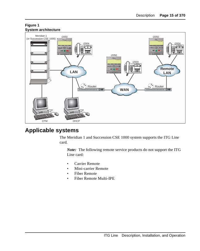
OverviewThe Meridian 1 and Succession Communication Server for Enterprise 1000 Internet Telephony Gateway (ITG) Line card supports the i2004 Internet Telephone and i2050 Software Phone by providing a communication gateway between the IP data network and the Meridian 1 and Succession CSE 1000. The Internet Telephone translates voice into data packets for transport using Internet Protocol (IP).
A Dynamic Host Configuration Protocol (DHCP) server can be used to provide the required information to enable the Internet Telephone network connection and connect to the ITG Line card. The Internet Telephone uses the IP network to communicate with the ITG Line card and the optional DHCP server. Figure 1 on page 15 shows a system block diagram.
For more information on the i2004 Internet Telephone and the i2050 Software Phone, refer to Internet Terminals: Description (553-3001-217).
553-3001-204 Standard 3.00 March 2002
Description Page 15 of 370
Figure 1System architecture
Applicable systemsThe Meridian 1 and Succession CSE 1000 system supports the ITG Line card.
Note: The following remote service products do not support the ITG Line card:
• Carrier Remote• Mini-carrier Remote• Fiber Remote• Fiber Remote Multi-IPE
RemoteLAN
OTM DHCP
LAN
WANRouterRouter
Meridian 1(or Succession CSE 1000)
i2050
i2004
i2050
i2004
i2050
i2004
ITG Line Description, Installation, and Operation
Page 16 of 370 Description
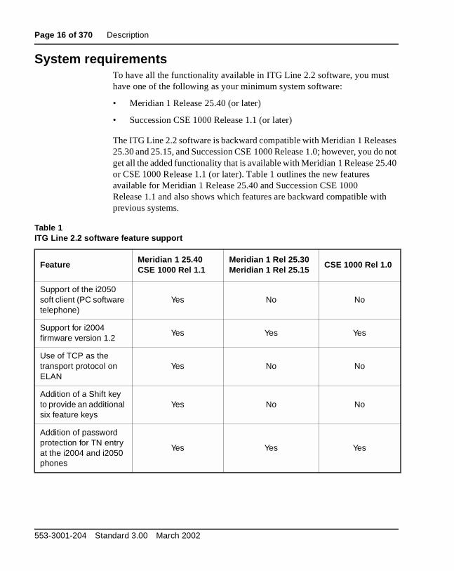
System requirementsTo have all the functionality available in ITG Line 2.2 software, you must have one of the following as your minimum system software:
• Meridian 1 Release 25.40 (or later)
• Succession CSE 1000 Release 1.1 (or later)
The ITG Line 2.2 software is backward compatible with Meridian 1 Releases 25.30 and 25.15, and Succession CSE 1000 Release 1.0; however, you do not get all the added functionality that is available with Meridian 1 Release 25.40 or CSE 1000 Release 1.1 (or later). Table 1 outlines the new features available for Meridian 1 Release 25.40 and Succession CSE 1000 Release 1.1 and also shows which features are backward compatible with previous systems.
Table 1ITG Line 2.2 software feature support
FeatureMeridian 1 25.40CSE 1000 Rel 1.1
Meridian 1 Rel 25.30Meridian 1 Rel 25.15
CSE 1000 Rel 1.0
Support of the i2050 soft client (PC software telephone)
Yes No No
Support for i2004 firmware version 1.2
Yes Yes Yes
Use of TCP as the transport protocol on ELAN
Yes No No
Addition of a Shift key to provide an additional six feature keys
Yes No No
Addition of password protection for TN entry at the i2004 and i2050 phones
Yes Yes Yes
553-3001-204 Standard 3.00 March 2002

Description Page 17 of 370
Note: Optivity Telephony Manager (OTM) is used throughout this document as the primary interface for ITG Line card administration. OTM 1.2 is the minimum recommended version.
Software deliveryThe Meridian 1 and Succession CSE 1000 ITG Line product supports software delivery through CD-ROM. The CD-ROM is inserted into the CD-ROM drive of the Optivity Telephone Manager (OTM) PC and subsequently downloaded to the ITG Line card.
The ITG Line software and related documentation such as General Release Bulletins can be downloaded from the Nortel Networks web site. For information on how to download the required software, see “Installation and configuration of ITG Line node” on page 117.
Required packagesThe ITG Line card requires the software packages listed in Table 2.
In order to configure the ITG Line in groups 5-7, the Fiber Network (FIBN) software package #365 is required.
Table 2Required packages
Package Package number
Digital Set Package (DSET) 88
Aries Terminal Package (ARIES) 170
ITG Line Description, Installation, and Operation

Page 18 of 370 Description
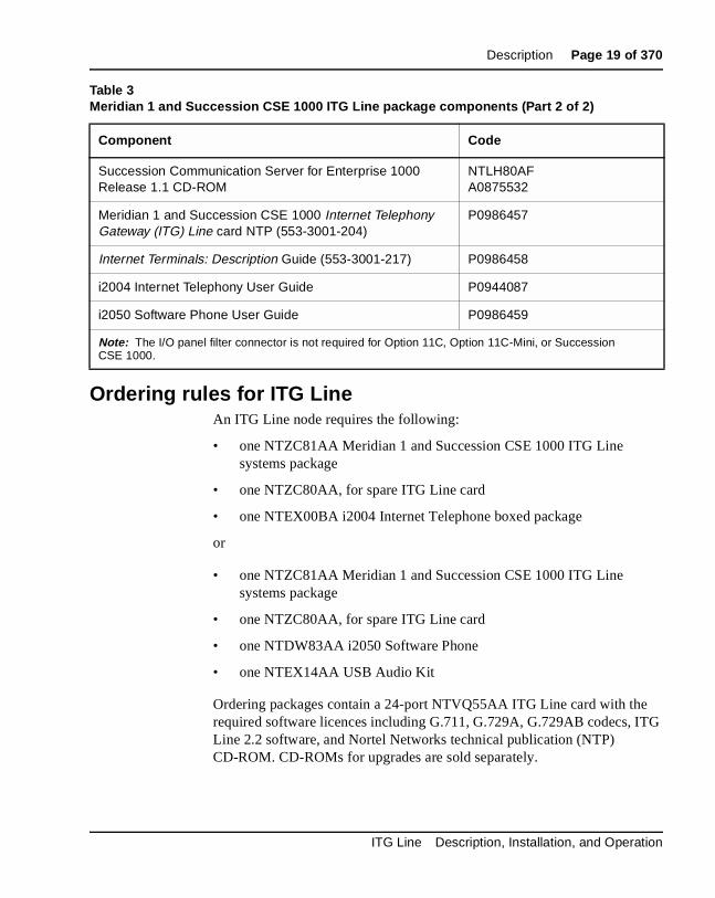
ITG Line package components listTable 3 lists ITG Line package components.
Table 3Meridian 1 and Succession CSE 1000 ITG Line package components (Part 1 of 2)
Component Code
Meridian 1 and Succession CSE 1000 ITG Line systems package, includes:
• Meridian 1 and Succession CSE 1000 ITG Line NTVQ55AA card assembly and required software licences
• PC maintenance cable
• Cables (ELAN, TLAN, and RS-232)
• ITG-specific 50-pin I/O panel filter connector (see Note)
• ITG Line software CD
• ITG Line card NTP
• Meridian Electronic Reference Library CD-ROM
• Succession CSE 1000 CD-ROM
NTZC81AA
Meridian 1 and Succession CSE 1000 ITG Line NTVQ55AA card assembly and required software licences for repair purposes
NTZC80AAA0804145These are the order codes for the NTVQ55AA ITG Line card.
PC maintenance cable NTAG81CAA0655007
ELAN, TLAN, and RS-232 interface cables NTMF94EAA0783470
ITG-specific 50-pin I/O panel filter connector for Meridian 1 (see Note below)
NTCW84JAA0783483
Meridian 1 and Succession CSE 1000 ITG Line software CD NTDW80ACA0870172
Meridian Electronic Reference Library R25.40 CD-ROM NTLH19ACA0859697
553-3001-204 Standard 3.00 March 2002
Description Page 19 of 370
Ordering rules for ITG LineAn ITG Line node requires the following:
• one NTZC81AA Meridian 1 and Succession CSE 1000 ITG Line systems package
• one NTZC80AA, for spare ITG Line card
• one NTEX00BA i2004 Internet Telephone boxed package
or
• one NTZC81AA Meridian 1 and Succession CSE 1000 ITG Line systems package
• one NTZC80AA, for spare ITG Line card
• one NTDW83AA i2050 Software Phone
• one NTEX14AA USB Audio Kit
Ordering packages contain a 24-port NTVQ55AA ITG Line card with the required software licences including G.711, G.729A, G.729AB codecs, ITG Line 2.2 software, and Nortel Networks technical publication (NTP) CD-ROM. CD-ROMs for upgrades are sold separately.
Succession Communication Server for Enterprise 1000 Release 1.1 CD-ROM
NTLH80AFA0875532
Meridian 1 and Succession CSE 1000 Internet Telephony Gateway (ITG) Line card NTP (553-3001-204)
P0986457
Internet Terminals: Description Guide (553-3001-217) P0986458
i2004 Internet Telephony User Guide P0944087
i2050 Software Phone User Guide P0986459
Note: The I/O panel filter connector is not required for Option 11C, Option 11C-Mini, or Succession CSE 1000.
Table 3Meridian 1 and Succession CSE 1000 ITG Line package components (Part 2 of 2)
Component Code
ITG Line Description, Installation, and Operation

Page 20 of 370 Description
OTM is a prerequisite and must be ordered separately. OTM automatically includes the ITG IP Phones application, which is used to configure, administer, and maintain the Meridian 1 and Succession CSE 1000 ITG Line card and Internet Telephone products.
Note: The Alarm and Notification application is not automatically included in OTM and must be ordered separately.
Meridian 1 and Succession CSE 1000 contains Incremental Software Management (ISM) limits for Internet Telephones. One Internet Telephone ISM parameter is required for each Internet Telephone configured.
DocumentationThe Internet Telephony Gateway Line: Description, Installation, and Operation (553-3001-204) is included with the standard documentation library and can also be ordered separately.
The Internet Terminals: Description (553-3001-217) is included with the standard documentation library and can also be ordered separately.
The Meridian 1 and Succession CSE 1000 i2004 Internet Telephone User Guide is sold separately from the i2004 Internet Telephone.
Note: A quick reference card is included with the i2004 Internet Telephone.
The Meridian 1 and Succession CSE 1000 i2050 Software Phone User Guide is sold separately from the i2050 Software Phone.
553-3001-204 Standard 3.00 March 2002

Description Page 21 of 370
ITG Line card descriptionThe ITG Line NTVQ55AA card plugs into an Intelligent Peripheral Equipment (IPE) shelf. Each ITG Line card occupies two slots.
ITG Line cards have an ELAN management Ethernet port (10BaseT) and a TLAN VoIP Ethernet port (10/100BaseT) on the I/O panel. There is an RS-232 Maintenance Port connection on the ITG Line card faceplate and an alternative connection to the same serial port on the I/O backplane.
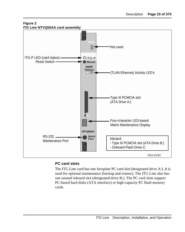
ITG Line controls, indicators, and connectorsFigure 2 on page 23 shows the ITG Line card faceplate components. The information in this section describes the components.
Faceplate componentsNWKThe faceplate connector labeled NWK is a 9-pin, sub-miniature D-type connector. The connector is not used for the ITG Line application.
ITG-P LED (Card Status)The red status faceplate LED indicates the enabled/disabled status of the 24 card ports. The LED is on (red) during the power-up or reset sequence. The LED remains lit until the card is enabled by Meridian 1 or Succession CSE 1000. If the LED remains on, the self-test failed, the card is disabled, or the card rebooted.
CAUTIONDo not connect maintenance terminals to both the faceplate and I/O panel serial maintenance port connections at the same time.
WARNINGThe NWK connector looks like a 9-pin serial connector. DO NOT connect a serial cable or any other cable to it. If you install a cable to the NWK connector, you will disable the TLAN.
ITG Line Description, Installation, and Operation
Page 22 of 370 Description
Reset switchPress the Reset switch to reset the card without having to cycle power to the card. This switch is normally used after a card software upgrade to the card or to clear a fault condition.
NWK Status LEDsNWK Status LEDs display the TLAN Ethernet activity.
• Green - The LED is on if the carrier (link pulse) is received from the TLAN Ethernet hub.
• Yellow - The LED flashes when there is TLAN data activity. During heavy traffic, the yellow LED can stay continuously lit.
Note: There are no Ethernet status LEDs for the ELAN management interface.
553-3001-204 Standard 3.00 March 2002
Description Page 23 of 370
Figure 2ITG Line NTVQ55AA card assembly
PC card slotsThe ITG Line card has one faceplate PC card slot (designated drive A:). It is used for optional maintenance (backup and restore). The ITG Line also has one unused inboard slot (designated drive B:). The PC card slots support PC-based hard disks (ATA interface) or high-capacity PC flash memory cards.
ITG-P
NWK
NTVQ55AA
NWKStatus
Reset
MaintPort
A:
553-9150
Not used
ITG-P LED (card status)
(TLAN Ethernet) Activity LED's
Reset Switch
Type III PCMCIA slot(ATA Drive A:)
Four-character LED-based Matrix Maintenance Display
RS-232Maintenance Port
Inboard:- Type III PCMCIA slot (ATA Drive B:)- Onboard Flash Drive C:
ITG Line Description, Installation, and Operation
Page 24 of 370 Description
Maintenance DisplayA four-character, LED-based, dot matrix display shows the maintenance status fault codes and other card state information.
RS-232 Maintenance Port (Maint Port)The ITG Line card faceplate provides a female DIN-8 serial maintenance port connection (labeled Maint Port). An alternative connection to the faceplate serial maintenance port exists on the NTMF94EA I/O panel breakout cable.
Backplane interfacesThe backplane connector provides ELAN, TLAN, alternate connection to the serial maintenance port DS-30X and Card LAN interfaces.
DS-30X voice/signalingDS30X carries Pulse Code Modulation (PCM) voice and proprietary signaling on the IPE backplane between the ITG Line card and the Intelligent Peripheral Equipment Controller (XPEC).
Card LANCard LAN carries card polling and initialization messages on the IPE backplane between the ITG Line card and the Intelligent Peripheral Equipment Controller (XPEC).
Assembly descriptionThe ITG Line card assembly is a two-slot motherboard and daughterboard combination. A PCI interconnect board connects the ITG motherboard and the DSP daughterboard.
CAUTIONDo not connect maintenance terminals or modems to the faceplate and I/O panel DB-9 male serial maintenance port at the same time.
553-3001-204 Standard 3.00 March 2002

Description Page 25 of 370
ITG Line card functional descriptionThe ITG Line card performs two separate functions:
• It acts as a gateway between the Time Division Multiplexing (TDM) voice switching network and the IP network.
• It acts as Terminal Proxy Server (TPS) or “virtual line card” for the i2004 Internet Telephone and i2050 Software Phone.
The TPS portion of the card connect through the ELAN port to the Meridian 1 or Succession CSE 1000 CPU through the CPU Ethernet port. The Gateway portion of the card connects to the Meridian 1 or Succession CSE 1000 through the DS30X backplane. The Gateway portion also receives call speech path setup and codec selection commands through the ELAN port. The Internet Telephone connects to both the Gateway and TPS functions through the TLAN port.
Gateway functional descriptionThe Gateway:
• registers with the PBX using the TN Registration messages
• accepts commands from the PBX to connect/disconnect audio channel
• uses RTP/RTCP protocol to transport audio between the gateway and the Internet Telephone
• encodes/decodes audio from PCM to and from the Internet Telephone’s format
• provides echo cancellation for the speaker on the i2004 Internet Telephone (not applicable to the i2050 Software Phone)
Virtual superloops, virtual TNs, and physical TNsVirtual TNs (VTNs) allow configuration of service data for an Internet Telephone, such as key layout and class of service, without requiring the Internet Telephone to be dedicated (hard-wired) to a given TN on the Meridian 1 and Succession CSE 1000 ITG Line card.
ITG Line Description, Installation, and Operation
Page 26 of 370 Description
Calls are made between an Internet Telephone and traditional telephone/trunks using the full Meridian 1 and Succession CSE 1000 feature set. Digital Signal Processor (DSP) channels are allocated dynamically for this type of call to perform the transcoding required to connect the Internet Telephone to the Time Division Multiplexing (TDM) network.
To create an Internet Telephone through the use of VTNs, you must create a virtual superloop in Overlay 97. Up to 1024 VTNs can be configured on a single virtual superloop for as Option 51C/61C/81/81C. Up to 128 VTNs can be configured on a single virtual superloop for as Option 11C/11C-Mini, leading to a maximum number of 640 VTNs for each Option 11C/11C-Mini.
Each ITG Line card provides 24 physical TNs. You configure the ITG physical TNs (IPTN) in Overlay 14. They appear as tie trunks without a route data block.
Virtual TNsVirtual TNs allow you to configure service data for a terminal, such as key layout and class of service, without requiring a physical terminal to be directly connected to the PBX.
The concentration of Internet Telephones is made possible by dynamically allocating a port (also referred to as a physical TN) of the ITG Line card for a TDM – Internet Telephone call. All Meridian 1 and Succession CSE 1000 speech path management is done with physical TNs instead of the virtual TNs.
The choice of the port is not restricted to the ITG Line where the Terminal Proxy Server (TPS) handling that particular Internet Telephone is running. The port can be chosen from the ITGs dedicated to the Internet Telephones. The Internet Telephones (virtual TNs) are defined on virtual superloops.
553-3001-204 Standard 3.00 March 2002

Description Page 27 of 370
A virtual superloop is a hybrid of real and phantom superloops. Like phantom superloops, no hardware (for example, XPEC or line card) is used to define and enable units on a virtual superloop. As with real superloops, virtual superloops use the time slot map to handle Internet Telephone (virtual TNs) to Internet Telephone calls.
Terminal Proxy Server descriptionThe Terminal Proxy Server (TPS) maintains a count of the number of telephones registered to the card. Each node has one active master. The active master broadcasts to all ITG Line cards and requests a response if it has room for another telephone. The maximum number of telephones for each ITG Line card is 96.
The Election function uses a selection process to determine the node’s master.
The Census function determines the ITG Line cards within a node.
Virtual Terminal Manager descriptionThe Virtual Terminal Manager (VTM):
• arbitrates application access to the Internet Telephones.
• manages all the telephones between the applications and the stimulus messaging to the telephone.
• maintains context sensitive states of the telephone (for example, display or lamp state).
• isolates telephone-specific information from the applications (for example, the number of display lines, number of characters for each display line, tone frequency, and cadence parameters).
Interactions with Internet TelephonesWhen you add an Internet Telephone to the network, the telephone sends a request to the DHCP server identifying itself as an Internet Telephone and requests IP parameters and a Connect Server address. The Internet Telephone then contacts the Connect Server which instructs the Internet Telephone to display a message on its display screen requesting the customer’s node number and TN.
ITG Line Description, Installation, and Operation
Page 28 of 370 Description
After the customer enters this information, the Internet Telephone contacts the Node Master which selects a TPS with sufficient capacity to register the Internet Telephone. The chosen TPS contacts the Internet Telephone and, if the Internet Telephone is valid, registers it with the Meridian 1 and Succession CSE 1000. The registration information is then saved to the Internet Telephone.
UnregistrationIf the ITG Line card detects a loss of connection with one of its registered Internet Telephones, it logs the event and sends an unregister message to the Meridian 1 or Succession CSE 1000 for that Internet Telephone.
CodecsCodec refers to the voice coding and compression algorithm used by the DSPs on the ITG Line card. Different codecs provide different levels of voice quality and compression properties. The specific codecs and the order in which they are used, is configured in the TPS and Meridian 1 and Succession CSE 1000. The ITG Line card supports the G.711, G.729A, and G.729AB codecs.
Signaling and messagingThe ITG Line sends Scan and Signaling Distribution (SSD) messages through the Meridian 1 or Succession CSE 1000 ELAN using the User Datagram Protocol (UDP). When tone service is provided, it is signaled to the TPS using new SSD messages sent through the ELAN.
Signaling protocolsSignaling between the Internet Telephone and the ITG Line card uses the Unified Networks IP Stimulus Protocol (UNIStim) with the Reliable User Datagram Protocol (RUDP) as the transport protocol.
RUDPReliable User Datagram Protocol (RUDP) is used for ELAN communications between the Meridian 1 or Succession CSE 1000 CPU and the ITG Line cards, and for TLAN communications between the ITG Line cards and the Internet Telephones. RUDP is another layer on top of UDP. RUDP is proprietary to Nortel Networks.
553-3001-204 Standard 3.00 March 2002

Description Page 29 of 370
The features of RUDP are:
• reliable communication system over a network
• packages are resent if an ACK is not received following a time-out
• messages arrive in the correct sequence
• duplicate messages are ignored
• loss of contact detection
When a data sequence is packetized and sent from source A to receiver B, the RUDP protocol adds a number to each packet header to indicate its order in the sequence.
• If the packet is successfully transmitted to B, B sends back an acknowledge message (ACK) to A, acknowledging that the packet has been received.
• If A receives no message within a configured time, it retransmits the packet.
• If B receives a packet without having first received its predecessor, it discards the packet and all subsequent packets, and an NAK (no acknowledge) message is sent to A, which includes the number of the missed packet. A retransmits the missed packet and continues from there.
UNIStimThe Unified Network IP Stimulus Protocol (UNIStim) is the single point of contact between the various server components and the Internet Telephone.
UNIStim is the stimulus-based protocol used for communication between an Internet Telephone and a Terminal Proxy Server on the ITG Line card.
ELAN TCP TransportA TCP implementation is introduced in ITG Line for the ELAN signaling between the ITG Line and the Call Server. TCP replaces the RUDP transport for signaling. This improves network performance in terms of efficiencies. Although TCP is used for the signaling protocol between the Call Server and the ITG Line card, RUDP still remains for the keep alive mechanism. This means RUDP messages are exchanged to maintain the link status between the Call Server and the ITG Line card.
ITG Line Description, Installation, and Operation

Page 30 of 370 Description
There is no change on the TLAN side signaling mechanism. IP phones continue to use the RUDP transport protocol to communicate with the ITG Line card.
The TCP protocol allows messages to be bundled. Unlike the RUDP transport which creates a separate message for every signaling message (such as display updates or key messages), the TCP transport bundles a number of messages and sends them as one packet.
Handshaking will be added to the Call Server and ITG Line software so that the TCP functionality is automatically enabled. A software version check is performed by the ITG Line application each time before it attempts to establish a TCP link with the Meridian 1 and Succession CSE 1000 CPU. If the version does not satisfy the minimum supported version (Meridian 1 Rel .40 or Succession CSE 1000 Rel 1.1), a RUDP link will be used instead.
ZonesTo optimize ITG Line traffic bandwidth use between different locations, the ITG Line network is divided into “zones” representing different topographical areas of the network. All Internet Telephones and ITG Line ports are assigned a zone number indicating the zone to which they belong.
When a call is made, the codecs used vary depending on which zone(s) the caller and receiver are in. By default:
• Codecs are selected to optimize voice quality (BQ - Best Quality) for connections between units in the same zone.
• Codecs are selected to optimize voice quality (BQ - Best Quality) for connections between units in different zones.
Each zone can be configured to optimize either voice quality or bandwidth usage for calls between users in that zone. Each zone can be configured to optimize either voice quality or bandwidth usage within a zone and all traffic going out of a zone.
See “VoIP bandwidth management zones” on page 64.
553-3001-204 Standard 3.00 March 2002

Description Page 31 of 370
ITG Line feature enhancementsShift key
The ITG Line feature introduces the functionality of the Shift key. The Shift key is also known as the Outbox key. The Shift key on an i2004 Internet Telephone is the third key from the lower right hand corner of the telephone with the icon of an arrow pointing up and to the right.
The Shift key is used to provide an additional six soft feature keys (6-11).
Pressing the Shift key causes the Feature key screen to switch to page 2 and the feature key labels to change accordingly.
Note: Pressing the Shift key has no effect if the features on page 2 are not configured. The feature keys on page 1 continues to be displayed.
The feature key indicators bind with keys. That is, if one feature key is in use and the icon for this key is on, then scrolling to the next page displays the icon of next page’s feature key.
An example of the operation follows:
A user has feature key on page 2 active and the telephone displays key labels and icons for keys 6-11. An incoming call for DN 0 arrives; the telephone alerts, the message waiting lamp flashes and the message “Shift for call” is displayed in the context area of the display. The icon indicator for the page 2 feature key does not change. The user must scroll to feature key page 1 to see the DN key and its flashing icon; the call can then be answered by pressing this key.
ITG Line Description, Installation, and Operation

Page 32 of 370 Description
Internet Telephone Installer PasswordThe Internet Telephone displays Node ID and Terminal Number (TN) of the telephone for five seconds as the telephone boots up. ITG Line introduces the availability of password protection for changing the TN on the Internet Telephone.
Administrator Internet Telephone Installer PasswordThis feature adds basic Internet Telephone Installer Password protection on the Internet Telephones to control registration with a virtual line TN on the Call Server. This feature does not provide a user password nor a station control password for Internet Telephones.
When the password is configured, the telephone screen shows the four digit Node ID and a Password prompt (see Figure 4 on page 34), instead of the Node ID and TN fields. When the user enters the password, an asterisk (*) is displayed for each digit entered so the actual password is not shown. Once the Node ID and Password are entered, the user presses OK. If the password passes the Connect Server’s authentication, a screen is displayed with the TN field.
If the Node ID and Password are not entered, the registration continues after five seconds and the TN is not displayed. If an invalid Node ID password is entered, the Node ID and Password screen is redisplayed. This screen will be redisplayed a maximum of two times, giving the technician a total of three chances to enter the password. After three failed attempts, the registration will continue as if no entry had been done at the telephone. The technician can reboot the telephone and try again if more tries are needed.
If the technician has entered a zero length (null) password, then the Node ID, TN, and Password screens are not displayed on the Internet Telephone during the registration process. This provides the most security as it prevents any entry of passwords or TNs from the Internet Telephone.
Temporary Internet Telephone Installer PasswordA Temporary Internet Telephone Installer Password can be configured, which allows the technician to give temporary user access to the TN for configuration. A temporary password removes the need to distribute the Node password and having to change it afterwards. The temporary password automatically deletes itself after it has been used the defined number of times or when the duration expires, whichever comes first.
553-3001-204 Standard 3.00 March 2002
Description Page 33 of 370
The following are examples of situations where the Temporary Internet Telephone Installer Password can be used:
• A department is installing i2050 soft clients. The technician creates a temporary password, sets an appropriate number of uses (such as allowing two logins for each telephone in case there is a problem the first time) and set the duration to expire by the end of the weekend. The password access automatically ends before Monday morning (or sooner if the number of uses expires).
• A telecommuter needs to install an Internet Telephone. The technician provides the temporary password, which expires the next day or after two uses. When the Internet Telephone Installer Password protection is enabled, the Set TN is not displayed as part of the Set Info sub menu of the Telephone Option menu. The telephone’s TN can be retrieved on the core CPU through the OVL 20 PRT DNB and Overlay 32 IDU, or Overlay 80 TRAC, or PDT> rlmShow. It can also be found on the ITG Line card through ITGL> isetShowByIP.
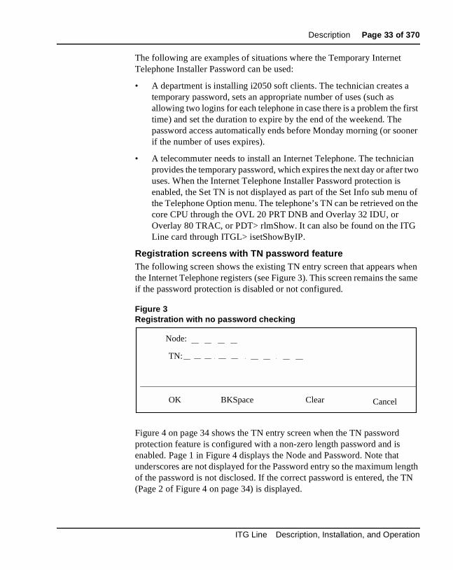
Registration screens with TN password featureThe following screen shows the existing TN entry screen that appears when the Internet Telephone registers (see Figure 3). This screen remains the same if the password protection is disabled or not configured.
Figure 3Registration with no password checking
Figure 4 on page 34 shows the TN entry screen when the TN password protection feature is configured with a non-zero length password and is enabled. Page 1 in Figure 4 displays the Node and Password. Note that underscores are not displayed for the Password entry so the maximum length of the password is not disclosed. If the correct password is entered, the TN (Page 2 of Figure 4 on page 34) is displayed.
Node:
TN:
OK BKSpace Clear Cancel
ITG Line Description, Installation, and Operation

Page 34 of 370 Description
Figure 4Registration with password checking
ITG Line CLI commands for password controlThe Internet Telephone Installer Passwords are configured on any ITG Line card in the node. The Internet Telephone Installer Password commands begin with “node” as they work at the node level. There are six new ITGL> CLI commands. For detailed information about these commands see Table 45 on page 278.
• nodePwdSet “password”
• nodePwdShow
• nodePwdTempPwdSet “temppwd”, uses, <time>
• nodeTempPwdClear
• nodePwdEnable
• nodePwdDisable
Node:
OK BKSpace Clear Cancel
Password:
Page 1:
TN:
OK BKSpace Clear Cancel
Page 2:
553-3001-204 Standard 3.00 March 2002

Description Page 35 of 370
When an ITG Line node is first installed, no administrator password or temporary password is defined and the password feature is in the disabled state. If enabled by the nodePwdEnable command prior to setting the node password through nodePwdSet, the password protection is enabled with a null password (so the password and TN prompts are never displayed on the Internet Telephones).
Password securityPassword security prevents casual access to an Internet Telephone's TN for the purpose of registering to a different virtual line TN on the Meridian 1 and Succession CSE 1000 Call Server after the Internet Telephones have been installed. Neither the telephone nor the ITG Line cards can provide encryption of the password.
Maintenance TelephoneAn Internet Telephone functions as a maintenance telephone when you define the class-of-service as MTA (Maintenance Telephone Allowed) in the Multi-line Telephone Administration program (LD 11). A maintenance telephone allows you to send commands to the system, but you can only use a subset of the commands that can be entered from a system terminal.
To access the system using the maintenance telephone, a Special Service Prefix (SPRE) code (defined in the customer data block) is entered followed by “91”. To enter commands, press the keys that correspond to the letters and numbers of the command (for example, to enter LD 42 return, key in 53#42##).
The following Overlays (OVLs) are accessible from an Internet Telephone operating as a maintenance telephone: 30, 32, 33, 34, 36, 37, 38, 41, 42, 43, 45, 46, 60, and 62.
Note: The above maintenance overlay operations are supported on Internet Telephones except for the Tone and Digit Switch (TDS) commands of OVL 34 and TONE command of OVL 46.
ITG Line Description, Installation, and Operation

Page 36 of 370 Description
AdministrationThe ITG Line card is administered through three management interfaces:
• A Graphical User Interface (GUI) provided by OTM 1.2 (or later).
• A Command Line Interface (CLI).
• Administration and maintenance overlays of Meridian 1 and Succession CSE 1000 Call Servers.
OTM ITG Line Internet Telephone applicationYou must use OTM to create a node, add cards to the node, transmit software to the cards, upgrade software, define SNMP alarms, select codecs, and other related tasks.
OTM is required for such tasks as:
• creating a node
• adding ITG Line cards to the node
• transmitting software to the ITG Line cards
• upgrading software
• defining SNMP alarms
• selecting codecs
Command Line InterfaceThe ITG Command Line Interface (CLI) provides a text-based interface to perform some specific ITG Line card installation, configuration, administration, and maintenance functions. You can establish a CLI session by connecting a TTY or PC to the card serial port or Telnet through the ELAN or TLAN IP address.
The CLI must be used to configure the leader card’s ELAN IP address so that OTM can communicate with the Leader card and the node.
ELAN TCP TransportA TCP implementation is introduced in ITG Line for the ELAN signaling between the ITG Line and the Call Server. Refer to “ELAN TCP Transport” on page 29.
553-3001-204 Standard 3.00 March 2002

Page 37 of 370
50
Meridian 1 and Succession CSE 1000 capacity engineering guidelinesContents
This section contains information on the following topics:
Overview . . . . . . . . . . . . . . . . . . . . . . . . . . . . . . . . . . . . . . . . . . . . . . . . 38
Capacity engineering . . . . . . . . . . . . . . . . . . . . . . . . . . . . . . . . . . . . . . . 38ITG Line capacity . . . . . . . . . . . . . . . . . . . . . . . . . . . . . . . . . . . . . . . 39Capacity engineering considerations . . . . . . . . . . . . . . . . . . . . . . . . 40Traffic capacity of ITG Line cards when supporting Internet Telephones . . . . . . . . . . . . . . . . . . . . . . . . . . . . . . . . . . . . . 41ISM parameters . . . . . . . . . . . . . . . . . . . . . . . . . . . . . . . . . . . . . . . . 42
Internet Telephone Engineering . . . . . . . . . . . . . . . . . . . . . . . . . . . . . . 43Traffic and Service Circuits . . . . . . . . . . . . . . . . . . . . . . . . . . . . . . . 43Gateway Channels Traffic Engineering . . . . . . . . . . . . . . . . . . . . . . 44Real time factors . .. . . . . . . . . . . . . . . . . . . . . . . . . . . . . . . . . . . . . . 45
Equipment considerations . . . . . . . . . . . . . . . . . . . . . . . . . . . . . . . . . . . 46Optional equipment . . . . . . . . . . . . . . . . . . . . . . . . . . . . . . . . . . . . . 46Required equipment . . . . . . . . . . . . . . . . . . . . . . . . . . . . . . . . . . . . . 46ITG specific I/O filter connectors . .. . . . . . . . . . . . . . . . . . . . . . . . . 47Identify the IPE card slots . . . . . . . . . . . . . . . . . . . . . . . . . . . . . . . . 48
Product compatibility with other ITG Line products . . . . . . . . . . . . . . 48
ITG Line card CPU resources . . . . . . . . . . . . . . . . . . . . . . . . . . . . . . . . 49
ITG Line Description, Installation, and Operation
Page 38 of 370 Meridian 1 and Succession CSE 1000 capacity engineering guidelines
OverviewThis chapter provides capacity engineering guidelines to help plan and engineer the Meridian 1 and Succession Communication Server for Enterprise 1000 to support the Internet Telephony Gateway (ITG) Line card and the i2004 Internet Telephone and the i2050 Software Phone.
Refer to “IP Network Engineering Guidelines” on page 51 for IP Network Engineering information.
Refer to “OTM setup to manage ITG Line nodes” on page 181 for information on how to configure Optivity Telephony Management (OTM) to support the ITG Line card and the Internet Telephone.
Refer to “Configuration of the DHCP server” on page 103 for engineering guidelines to set and configure the Dynamic Host Configuration Protocol (DHCP) server to support the ITG Line card and Internet Telephones.
Capacity engineeringThis section explains how to calculate Meridian 1 and Succession CSE 1000 system capacity when engineering the ITG Line card for an Internet Telephone.
There are restrictions on the number of Internet Telephones that can be installed on certain system types. This limitation is a result of the time required to re-register all of the Internet Telephones after the Meridian 1 and Succession CSE 1000 initialize. Please refer to the Read Me First document for more information. This document is located on the software CD and on the Software Distribution web site.
553-3001-204 Standard 3.00 March 2002
Meridian 1 and Succession CSE 1000 capacity engineering guidelines Page 39 of 370
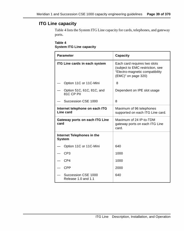
ITG Line capacityTable 4 lists the System ITG Line capacity for cards, telephones, and gateway ports.
Table 4System ITG Line capacity
Parameter Capacity
ITG Line cards in each system Each card requires two slots (subject to EMC restriction, see “Electro-magnetic compatibility (EMC)” on page 320)
— Option 11C or 11C-Mini 8
— Option 51C, 61C, 81C, and 81C CP PII
Dependent on IPE slot usage
— Succession CSE 1000 8
Internet telephone on each ITG Line card
Maximum of 96 telephones supported on each ITG Line card.
Gateway ports on each ITG Line card
Maximum of 24 IP-to-TDM gateway ports on each ITG Line card.
Internet Telephones in the System
— Option 11C or 11C-Mini 640
— CP3 1000
— CP4 1000
— CPP 2000
— Succession CSE 1000 Release 1.0 and 1.1
640
ITG Line Description, Installation, and Operation
Page 40 of 370 Meridian 1 and Succession CSE 1000 capacity engineering guidelines
Capacity engineering considerationsNumber of Internet Telephones in the system
• Option 11C or 11C-Mini - There is a maximum of 640 Internet Telephones for an Option 11C or 11C-Mini.
• Option 51C, 61C, 81C, and 81C CP PII - The number of Internet Telephones is determined by the engineering of real time usage, traffic capacity, network loop usage, and IPE slot usage, up to the maximum stated in Table 4 on page 39 for the specific CPU type.
• Succession CSE 1000 Release 1.0 and 1.1 - There is a maximum of 640 Internet Telephones.
— For normal traffic engineering, provision up to 1024 virtual TNs for each virtual superloop.
— For a non-blocking virtual superloop configuration, do not exceed 120 virtual TNs for each virtual superloop.
Note: In Option 51C/61C/81/81Cs, virtual superloops contend for the same range of loops with phantom, standard, and remote superloops, digital trunk loops and all service loops.
Maximum number of ITG Line cards in the system
• Option 11C or 11C-Mini - Up to eight ITG Line cards can be installed.
• Option 51C, 61C, 81C, and 81C CP PII - The number of ITG Line cards is determined by IPE slot usage.
• Succession CSE 1000 - Up to eight ITG Line cards can be installed.
Option 11C
• A maximum of five virtual superloops, 96-112 with cards 61-80 (640 telephones).
Note: Virtual superloops, phantom superloops, and real superloops contend for the same five superloops in Option 11C/11C-Mini.
553-3001-204 Standard 3.00 March 2002

Meridian 1 and Succession CSE 1000 capacity engineering guidelines Page 41 of 370
Traffic capacity of ITG Line cards when supporting Internet Telephones
Each ITG Line card has 24 ports that are used for establishing a voice connection between Internet Telephones and non-Internet Telephones (such as digital telephones or public network). To configure a system as non-blocking (as is typically the case for ACD configurations), ensure only 24 Internet Telephones are registered on each card.
A registered telephone is not synonymous with a configured telephone. When a telephone is registered, it is though the telephone is plugged in. When the telephone de-registers, it is as though the telephone was unplugged. Registration consists of two steps:
1 Verifying the user’s TN is valid and has not yet been registered.
2 Associating the TN on the Meridian 1 and Succession CSE 1000 side.
If an Internet Telephone is unplugged, it automatically becomes un-registered after a pre-determined time-out. This limitation on simultaneous calls depends not on the number of ports, but on the number and type of calls.
A call between two Internet Telephones on the same Meridian 1 or Succession CSE 1000 ITG Line node does not use the ITG Line card as a voice path across the data network.
ITG Line cards in a Meridian 1 and Succession CSE 1000 are pooled by customer number, are assigned dynamically, and are allocated preferentially by matching bandwidth management zones. For more details, see “VoIP bandwidth management zones” on page 64. An Internet Telephone can be assigned any port of any ITG Line card within the Meridian 1 and Succession CSE 1000 system.
Note: The average number of Busy Hour Call Attempts must not exceed an average of 1200 BHCA each hour.
ITG Line Description, Installation, and Operation

Page 42 of 370 Meridian 1 and Succession CSE 1000 capacity engineering guidelines
Refer to the following three examples for further clarification:
Example 1:150 Internet Telephones with "typical" business usage of 600 call seconds per hour (CCS) for each telephone on average (for example, 5 calls of 120 seconds duration per hour)
— 150 x 6 CCS = 900 CCS
— 2 ITG Line cards required (see Table 5 on page 44)
Example 2:500 telephones with "heavy" business usage of 12 CCS for each telephone on average (for example, 6-7 calls of 180 seconds duration every hour)
— 500 x12 CCS = 6000 CCS
— 8 ITG Line cards are required (see Table 5 on page 44 - 8 ITG Line cards support up to 6013 CCS)
Example 3:48 Call Center Agents with an allocation of 36 CCS for each telephone
— 2 ITG Line cards are required (48 ports required/24 ports for each ITG Line card = 2 ITG Line cards)
Note: For Call Center Agents, it is recommended that one ITG Line port be provisioned for each agent.
ISM parametersCustomers must purchase one Internet Telephone ISM parameter for each Internet Telephone installed on Meridian 1 and Succession CSE 1000 systems. The default is zero. A new ISM parameter uses the existing Meridian 1 and Succession CSE 1000 keycode to enable the Internet Telephone in the Meridian 1 or Succession CSE 1000 system software.
For a Meridian 1 system, the required ISM parameter depends on the system configuration:
• NTZC82AA Internet Telephone Software Parameter (Option 51C, 61C, 81C, and 81C CP PII System)
• NTZC84AA Internet Telephone Software Parameter (Option 11C/11C-Mini System)
553-3001-204 Standard 3.00 March 2002
Meridian 1 and Succession CSE 1000 capacity engineering guidelines Page 43 of 370
For a Succession CSE 1000 system, the required ISM parameter depends on the system configuration:
• NTM450AA Basic
• NTM451AA Advanced
• NTM452AA Premium
If you expand the ISM limits for the Internet Telephones, you must order and install a new Meridian 1 and Succession CSE 1000 keycode. Refer to the Incremental Software Management feature module in the Features and Services (553-3001-306) NTP.
Internet Telephone Engineering Traffic and Service Circuits
Virtual loops use software resources for tracking speech path traffic usage and Call Detail Recording. There are 120 of these resources for each virtual loop. The engineering of Internet Telephones is similar to that for existing digital telephones (based upon 3500 CCS for each virtual loop).
The ITG Line gateway channels are engineered the same as trunks between the TDM switching fabric and the IP network. The TDS/Conference circuits are engineered for Internet Telephones as well as for existing digital telephones (one TDS/CONF card for each half group of Internet Telephones).
ITG Line Description, Installation, and Operation

Page 44 of 370 Meridian 1 and Succession CSE 1000 capacity engineering guidelines
Gateway Channels Traffic EngineeringConfigure no more than five ITG Line cards on each superloop to eliminate the possibility of blocking due to insufficient talkslots (for example, 5 ITG Line cards x 24 ports = 120 talkslots). Use Table 5 to determine the number of ITG Line cards required to maintain the recommended capacity.
Table 5 (Part 1 of 2)ITG Line card recommendations based on CCS capacity
The Internet Telephone blocking probability is 0.005.
Number of ITG Line cards Capacity CCS
1 511
2 1232
3 1996
4 2780
5 3577
6 4383
7 5196
8 6013
9 6835
10 7660
11 8488
12 9318
13 10144
14 10983
15 11818
16 12657
17 13496
553-3001-204 Standard 3.00 March 2002

Meridian 1 and Succession CSE 1000 capacity engineering guidelines Page 45 of 370
Note 1: CCS is the number of hundred call seconds per hour.
Note 2: If the number of ITG Line card exceeds 20, add 801 CCS to the total capacity for each additional card.
Real time factorsThe real time factors for Internet Telephones are given in Table 6.
The total real time capacity of the Meridian 1 and Succession CSE 1000 depends on factors such as:
• calling patterns
• feature operations
• telephone and trunk signaling
• system CPU capacity
18 14335
19 15177
20 16020
Table 6Real time factors for Internet Telephones
Call scenario Real time Factors
1 - way inbound 0.78
1 - way outbound 1.59
2 - way 2.95
Table 5 (Part 2 of 2)ITG Line card recommendations based on CCS capacity
The Internet Telephone blocking probability is 0.005.
Number of ITG Line cards Capacity CCS
ITG Line Description, Installation, and Operation
Page 46 of 370 Meridian 1 and Succession CSE 1000 capacity engineering guidelines
These factors are used to provision the maximum number of Internet Telephones supported on specific Meridian 1 and Succession CSE 1000 systems. These factors also describe the impact of using Internet Telephones relative to real time usage for a basic call between two 2500 telephones. Please refer to Capacity Engineering (NTP 553-3001-149) for further information.
Equipment considerationsThis section lists the required and optional equipment that can be used to install, configure, and maintain the ITG Line card and Internet Telephone products.
Optional equipmentThe optional equipment includes:
• A server configured with Dynamic Host Configuration Protocol (DHCP). For example, you can use a Nortel NetID server.
• An external modem router to allow remote dial-up connection to ELAN for technical support (The Nortel Networks RM356 modem router is recommended.).
Required equipmentThe required equipment includes:
• A PC with OTM 1.2 (or later) installed. Refer to “OTM setup to manage ITG Line nodes” on page 181 for PC configuration information.
• A local TTY or terminal in a switchroom. This is required for leader 0 configuration.
• Two shielded CAT 5 Ethernet cables to connect the ITG Line card to an external switch (recommended) or hub equipment.
• A 10/100BaseT Ethernet port (optional auto-sensing) to support TLAN and 10BaseT ELAN network connections.
• A 10/100BaseT Ethernet port (optional auto-sensing) in each location where an Internet Telephone resides.
• Serial cables.
553-3001-204 Standard 3.00 March 2002
Meridian 1 and Succession CSE 1000 capacity engineering guidelines Page 47 of 370
ITG specific I/O filter connectorsFor Meridian 1 Option 51C/61C/81/81C, the standard IPE module I/O filtering is provided by the 50-Pin filter connectors mounted in the I/O Panel on the back of the IPE shelf. The filter connector attaches externally to the MDF cables and internally to the NT8D81AA Backplane to the I/O Panel ribbon cable assembly.
For 100BaseTX TLAN operation, the standard I/O filter connector must be replaced with the NTCW84JA ITG Line-specific I/O filter connector for the leftmost of the two card slots occupied by the NTVQ55AA ITG Line card. Refer to “Install NTCW84JA ITG-specific I/O Panel Filter Connector for Option 51C/61C/81/81C” on page 122 for installation instructions.
For Option 11C, 11C-Mini, and Succession CSE 1000 systems, the standard I/O filter connector already supports 100BaseTX TLAN operation.
CAUTIONFor Meridian 1 systems manufactured during the period of 1998-1999 and shipped in North America, the IPE modules have the NT8D81BA Backplane to I/O Panel ribbon cable assembly with a non-removable Filter Connector. The NT8D81BA is compatible with 10BaseT TLAN, but if you require a 100BaseTX TLAN, you need to order and install the NT8D81AA Backplane to I/O Panel ribbon cable assembly. Do not try to install the NTCW84JA Filter Connector onto the existing non-removable Filter Connector.
If required for your site, see “Replace cable NT8D81BA with NT8D81AA” on page 293.
ITG Line Description, Installation, and Operation

Page 48 of 370 Meridian 1 and Succession CSE 1000 capacity engineering guidelines
Identify the IPE card slotsDepending on the Meridian 1 module you are using, the ITG Line card has to be installed in a certain slot. Use Table 7 to identify the IPE card slots selected for the ITG Line card.
Product compatibility with other ITG Line productsNortel Networks manufactures four Voice Over IP (VoIP) products in addition to the ITG Line. This section explains how the ITG Line card relates to the ITG Line products listed below:
• Meridian 1 and Succession CSE 1000 Internet Telephony Gateway Line 1.0 card/IP Telecommuter
• Meridian 1 Internet Telephony Gateway Trunk 1.0 card/Basic per-trunk signaling
• Meridian 1 Internet Telephony Gateway Trunk 2.0 card/ISDN Signaling Link
• 802.11 Wireless IP Gateway
Each ITG Line product uses TLANs and ELANs that can co-exist with each other. All cards within a node must be on the same TLAN subnet. They can share the same TLANs, and must share the same ELAN. You need to engineer the traffic on the TLAN to consider all ITG Line applications.
For EMC compliance, add up all the ITG Line products to stay within EMC limits.
The ITG Line cards require two slots in a module or cabinet.
Table 7ITG Line installation by module type
Meridian 1 modules ITG Line card slots
NT8D37BA/EC IPE modules, NT8D11BC/ED CE/PE modules
All available IPE card slots.
NT8D37AA/DC IPE modules 0, 4, 8, and 12
NT8D11AC/DC CE/PE modules 0
553-3001-204 Standard 3.00 March 2002

Meridian 1 and Succession CSE 1000 capacity engineering guidelines Page 49 of 370
ITG Line card CPU resourcesThe Internet Telephones shares the CPU resources of the ITG Line cards. Each Internet Telephone is controlled by one of the ITG Line cards. Up to 96 Internet Telephones can be registered with a single ITG Line card.
For calls between Internet Telephones:
• 24 gateway channels are supported by the card on the system.
• Calls through each of the 24 gateways also utilize the CPU resources of the ITG Line cards.
• The voice media stream is carried by IP packets directly between the telephones in the same system over the IP network.
On a traditional telephone, the tones are generated by Meridian 1 and Succession CSE 1000. The Internet Telephone can generate tones that originate on the original switch, so the tones do not suffer from distortion caused by compression codecs such as G.729A.
ITG Line Description, Installation, and Operation

Page 50 of 370 Meridian 1 and Succession CSE 1000 capacity engineering guidelines
553-3001-204 Standard 3.00 March 2002
Page 51 of 370
94
IP Network Engineering GuidelinesContents
This section contains information on the following topics:
Overview . . . . . . . . . . . . . . . . . . . . . . . . . . . . . . . . . . . . . . . . . . . . . . . . 52
IP address requirements for the ITG Line card . . . . . . . . . . . . . . . . . . . 52Node IP requirements . . . . . . . . . . . . . . . . . . . . . . . . . . . . . . . . . . . . 53ITG Line card IP address requirements . . . . . . . . . . . . . . . . . . . . . . 54
IP network assessment procedure . . . . . . . . . . . . . . . . . . . . . . . . . . . . . 55
Codecs . . . . . . . . . . . . . . . . . . . . . . . . . . . . . . . . . . . . . . . . . . . . . . . . . . 57
Calculate ITG Line traffic requirements . . . . . . . . . . . . . . . . . . . . . . . . 58TLAN traffic calculations . .. . . . . . . . . . . . . . . . . . . . . . . . . . . . . . . 59TLAN engineering example . . . . . . . . . . . . . . . . . . . . . . . . . . . . . . . 61
Assess WAN link resources . . . . . . . . . . . . . . . . . . . . . . . . . . . . . . . . . 62WAN traffic calculations . . . . . . . . . . . . . . . . . . . . . . . . . . . . . . . . . 62WAN engineering example . . . . . . . . . . . . . . . . . . . . . . . . . . . . . . . 63
VoIP bandwidth management zones . . . . . . . . . . . . . . . . . . . . . . . . . . . 64
Relationship between zones and domains . . . . . . . . . . . . . . . . . . . . . . . 66Link utilization assessment . .. . . . . . . . . . . . . . . . . . . . . . . . . . . . . . 66Estimating network loading due to ITG Line . .. . . . . . . . . . . . . . . . 67
Set service parameters . . . . . . . . . . . . . . . . . . . . . . . . . . . . . . . . . . . . . . 70Quality of Service (QoS) mechanism . .. . . . . . . . . . . . . . . . . . . . . . 70ITG Line card and Internet Telephone port numbers . . . . . . . . . . . . 71Measure intranet Quality of Service . .. . . . . . . . . . . . . . . . . . . . . . . 72
ITG Line ELAN and TLAN configuration . . . . . . . . . . . . . . . . . . . . . . 90General requirements . . . . . . . . . . . . . . . . . . . . . . . . . . . . . . . . . . . . 90Separate subnet configuration . . . . . . . . . . . . . . . . . . . . . . . . . . . . . 91ELAN and TLAN Half and Full Duplex operation . . . . . . . . . . . . . 91
ITG Line Description, Installation, and Operation

Page 52 of 370 IP Network Engineering Guidelines
Subnet configuration for TLAN and ELAN ports . . . . . . . . . . . . . . 93I/O filter connector . . . . . . . . . . . . . . . . . . . . . . . . . . . . . . . . . . . . . . 94
OverviewThis chapter provides guidelines and recommendations to help plan, engineer, and test the ITG Line card and Internet Telephone network.
The following procedures are contained within this chapter:
• Procedure 1, “Network assessment procedure” on page 55
• Procedure 2, “TLAN traffic calculation procedure” on page 59
• Procedure 3, “WAN traffic calculation procedure” on page 62
• Procedure 4, “Link utilization assessment procedure” on page 66
See “Configuration of the DHCP server” on page 103, for engineering guidelines to set up and configure the Dynamic Host Configuration Protocol (DHCP) server to support the ITG Line card and Internet Telephones.
IP address requirements for the ITG Line cardThis section describes the IP address requirements for each node, for each card, and for each Internet Telephone.
A node is a group of ITG Line cards. Each card within a node has two IP addresses - one for the Telephony LAN (TLAN) and one for the Meridian 1 or Succession CSE 1000 Embedded LAN (ELAN). Each node has one Node IP address on the TLAN, which is dynamically assigned to the connection server on the node master. The Internet Telephone uses the Node IP address during the registration process.
All ELAN addresses for all nodes must be on one subnet. All ELAN addresses must be on the same subnet as the Meridian 1 or Succession CSE 1000 Core ELAN. All TLAN addresses must be in the same subnet for a given node.
553-3001-204 Standard 3.00 March 2002

IP Network Engineering Guidelines Page 53 of 370
Node IP requirements
The default setting of separate ELAN and TLAN subnets offers the following features:
• Separate subnets are easier to configure for traffic management and quality of service (QoS).
• Separate subnets protect the Meridian 1 and Succession CSE 1000 ELAN from general LAN traffic, including broadcast and multicast storms
• Separate subnets are more secure against unauthorized access
Separate subnet Node IP address requirementsFigure 5 on page 54 shows an example of the ITG Line Node General tab with IP addresses configured for separate subnets. You must accept the default configuration of separate subnets. The terms in the list below are used to define the fields in the OTM application:
• Voice LAN Node IP address - The Voice LAN is also called the Telephony LAN (TLAN). This alias IP address appears dynamically on the TLAN port of one card in the node, the Leader or node master.
• Management LAN gateway IP address - The Management LAN is also called the Embedded LAN (ELAN)
• Management LAN subnet mask
• Voice LAN subnet mask
CAUTIONYou must use separate subnets with the ITG Line cards for ELAN and TLAN.
ITG Line Description, Installation, and Operation

Page 54 of 370 IP Network Engineering Guidelines
Figure 5Node IP address requirements example (separate subnets)
ITG Line card IP address requirementsThe IP address information for each card is set in the Configuration tab of the ITG Node Properties window of the IP Telephony Gateway - IP Phones application. The IP address requirements for each card depend on the node subnet option.
You must provide an IP address for an ELAN and TLAN port. On the ELAN, all cards must be on the same subnet, which is the same subnet that the Meridian 1 and Succession CSE 1000 is connected to. On the TLAN, all cards in a node must be on the same subnet.
The ELAN address is the same as the Management MAC address. The Management MAC address for each card is assigned during manufacturing and is unchangeable. Locate the faceplate sticker on the ITG Line card. The ELAN/Management MAC address is the MOTHERBOARD Ethernet address.
553-3001-204 Standard 3.00 March 2002

IP Network Engineering Guidelines Page 55 of 370
Separate subnet ITG Line card IP address requirementsYou must use separate subnets for the ITG Line node (see Figure 5 on page 54). Each ITG Line card requires a:
• Management IP address
• Voice IP address
• Management MAC
• Voice LAN gateway IP address
IP network assessment procedureAn efficient ITG Line network design begins with an understanding of traffic and the underlying network that carries the traffic. To determine the network requirements of the specific system, the technician must perform the steps in Procedure 1.
Procedure 1Network assessment procedure
1 Estimate the amount of traffic the Meridian 1 or Succession CSE 1000 will process through the ITG Line network. See “Calculate ITG Line traffic requirements” on page 58.
2 Assess whether the existing corporate intranet can adequately support voice services. See “Calculate ITG Line traffic requirements” on page 58 and “Assess WAN link resources” on page 62.
3 Organize the ITG Line network into “zones” representing different topographical areas of the network that are separated according to bandwidth considerations. See “VoIP bandwidth management zones” on page 64.
4 Set a variety of service parameters to improve service and coordinate (with the IP administrator) the prioritization of voice packets with data traffic. See “Set service parameters” on page 70.
ITG Line Description, Installation, and Operation

Page 56 of 370 IP Network Engineering Guidelines
5 Provide the necessary IP network infrastructure:
• 10BaseT or 100BaseTX Ethernet connection.
• IP address. Each ITG Line card requires 10BaseT ELAN or 10/100BaseT TLAN unicast IP address.
• One additional IP address for each node. The node IP address is the TLAN for a subnet.
—————————— End of Procedure ——————————
After completing the network assessments, the technician can design and implement the ITG Line network. This can involve modifications to both the ITG Line elements and to the existing network. Post-installation network measurements (see page 88) must be made on a regular basis to make sure QoS standards are maintained. Figure 6 shows an example of the TLAN and ELAN topology.
Figure 6TLAN and ELAN Topology
MAT/OTMDHCP
Meridian 1
DS30X
ITGL Card(in IPE Shelf)
T-LAN
T-LAN / E-LAN Topology
E-LANPRI
ITGLC
553-3001-204 Standard 3.00 March 2002

IP Network Engineering Guidelines Page 57 of 370
CodecsThe Internet Telephones and ITG Line cards support different codecs and codec parameters with different compression rates and audio quality. The Meridian 1 and Succession CSE 1000 selects the appropriate codecs based on user-configurable parameters. For instance, an Internet Telephone-to-Internet Telephone within a LAN can be set up using G.711 at 64 Kbps. For an Internet Telephone-to-Internet Telephone call over a WAN, the call can be set up using G.729A or G.729AB at 8 Kbps. These data rates and the Voice Gateway Channel Server on the ITG Line card are for the voice stream only. Packet overhead is not included.
The Terminal Proxy Server (TPS) and the Voice Gateway Channel Server on the ITG Line card have a predefined table of up to 32 codec option sets that can be supported. The first entry in the table has the highest quality audio (BQ = Best Quality) and requires the largest bandwidth. The last entry requires the least bandwidth (BB = Best Bandwidth) with some sacrifice in voice quality.
When the Call Server sets up a Call Server connection between an Internet Telephone-to-Internet Telephone or Internet Telephone-to-Voice Gateway Channel Server, the predefined table determines which codec it will select for that connection. This information is provided to the Meridian 1 and Succession CSE 1000 as part of the Internet Telephone registration sequence. For more information about the registration sequence, refer to “Configuration of the DHCP server” on page 103. The Meridian 1 and Succession CSE 1000 use this information to set up a speech path to select a codec that both endpoints support. As part of zone management, it further selects the codec based on whether it is trying to optimize quality (BQ) or bandwidth (BB).
When you configure the ITG Line card, select two codecs - a high-quality (BQ) codec and a bandwidth-efficient (BB) codec. Figure 7 on page 58 shows the list of supported codecs. The ITG Line product supports A-law and Mu-law.
CAUTIONWhen voice compression codecs are used, voice quality is impaired if end-to-end calls include multiple compressions.
ITG Line Description, Installation, and Operation
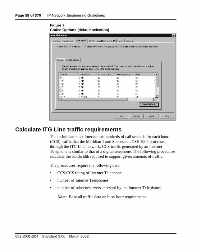
Page 58 of 370 IP Network Engineering Guidelines
Figure 7Codec Options (default selection)
Calculate ITG Line traffic requirementsThe technician must forecast the hundreds of call seconds for each hour (CCS) traffic that the Meridian 1 and Succession CSE 1000 processes through the ITG Line network. CCS traffic generated by an Internet Telephone is similar to that of a digital telephone. The following procedures calculate the bandwidth required to support given amounts of traffic.
The procedures require the following data:
• CCS/CCS rating of Internet Telephone
• number of Internet Telephones
• number of subnets/servers accessed by the Internet Telephones
Note: Base all traffic data on busy hour requirements.
553-3001-204 Standard 3.00 March 2002

IP Network Engineering Guidelines Page 59 of 370
The result of the calculation provides estimated values for the following:
• total TLAN bandwidth requirement
• WAN bandwidth requirement for each subnet or server/router
The technician must consider the impact of incremental ITG Line traffic on routers and LAN resources in the intranet. LAN segments can become saturated, and routers can experience high CPU use. A customer must consider re-routing scenarios in a case where a link is down.
TLAN traffic calculationsTo calculate the total TLAN requirement, add together all sources of traffic destined for the Internet Telephony network using the same LAN. The data rate for a TLAN is the total bit rate. The total subnet traffic is measured in Erlangs. An Erlang is a telecommunications traffic measurement unit and it is used to describe the total traffic volume of one hour. Network designers use these measurements to track network traffic patterns. To calculate the TLAN traffic, follow the step in Procedure 2.
Procedure 2TLAN traffic calculation procedure
1 Total subnet traffic is the sum of (measured in Erlangs):
• number of Internet Telephones × CCS/CCS rating)
• voice gateways on ITG Line card
• WAN connection
Note: Each source of traffic has a different CCS rating. Calculate the subnet traffic for each source of traffic and add the amounts to get the total.
2 Use the number of Erlangs to calculate the equivalent number of lines by using the calculator at the following web site:
http://www.erlang.com/calculator/erlb
Note: Assume a blocking factor of 1% (0.010).
3 Find the TLAN bandwidth use (Kbps) in Table 8 on page 60 based on the codec used for the traffic source.
ITG Line Description, Installation, and Operation

Page 60 of 370 IP Network Engineering Guidelines
4 Calculate the bandwidth of a subnet using the following calculation:
Bandwidth for each subnet equals the total number of lines multiplied by the TLAN bandwidth usage, that is:
Subnet bandwidth = Total number of lines x TLAN bandwidth usage
5 Repeat steps 1 to 4 for each subnet.
6 To calculate the total TLAN traffic, add the total bandwidth for each subnet calculation.
—————————— End of Procedure ——————————
Table 8TLAN and WAN IP bandwidth usage for each ITG Line card port
Codec typePacket
duration (ms)
Voice payload (bytes)
VADPeak
bandwidth (Kbps)
Average bandwidth
(Kbps)
G.711(64 Kbps)
20 160 Off 90.40 90.40
30 240 Off 81.60 81.60
G.729A(8 Kbps)
20 20 Off 34.40 34.40
30 30 Off 25.60 25.60
40 40 Off 21.20 21.20
50 50 Off 18.50 18.56
Note 1: The bandwidth estimates assume a Full Duplex connection.Note 2: For Half Duplex connections, such as Half Duplex Ethernet, the bandwidth estimates must be doubled.Note 3: The overhead is assumed to be for Ethernet connections and is comprised of: 8 bytes of Ethernet Preamble, 14 bytes of Ethernet header, 20 bytes of IP, 8 bytes of UDP, 12 bytes of RTP Header, 4 bytes of Ethernet check sum. Total Payload Encapsulation of 66 bytes. Note 4: Different transport types will have slightly different bandwidth requirements.
Note 5: The average bandwidth is reduced from the peak bandwidth by the use of silence suppression (VAD).
Note 6: The reduction due to VAD is assumed to be 40%.
553-3001-204 Standard 3.00 March 2002

IP Network Engineering Guidelines Page 61 of 370
TLAN engineering exampleThe following is an example of calculating TLAN bandwidth.
1 Subnet A: 28 Internet Telephones x 6 CCS/36 = number of Erlangs
For G. 729 Annex AB with silence suppression, TLAN bandwidth usage is 25.6 Kbps.
Subnet A bandwidth = 4.66 lines x 25.6 Kbps = 153.6 Kbps
2 Subnet B: 72 Internet Telephones, average 5 CCS/Internet Telephone.
Subnet B total Erlangs = 72 x 5/36 = 10
Subnet B bandwidth = 10 x 25.6 = 256 Kbps
3 Subnet C: 12 Internet Telephones, average 6 CCS/Internet Telephone.
Subnet C total Erlangs = 12 x 6/36 = 2
Subnet C bandwidth = 2 x 25.6 = 51.2 Kbps
G.729AB(8 Kbps)
20 20 On 34.40 20.64
30 30 On 25.60 15.36
40 40 On 21.20 12.72
50 50 On 18.56 11.14
Codec typePacket
duration (ms)
Voice payload (bytes)
VADPeak
bandwidth (Kbps)
Average bandwidth
(Kbps)
Note 1: The bandwidth estimates assume a Full Duplex connection.Note 2: For Half Duplex connections, such as Half Duplex Ethernet, the bandwidth estimates must be doubled.Note 3: The overhead is assumed to be for Ethernet connections and is comprised of: 8 bytes of Ethernet Preamble, 14 bytes of Ethernet header, 20 bytes of IP, 8 bytes of UDP, 12 bytes of RTP Header, 4 bytes of Ethernet check sum. Total Payload Encapsulation of 66 bytes. Note 4: Different transport types will have slightly different bandwidth requirements.
Note 5: The average bandwidth is reduced from the peak bandwidth by the use of silence suppression (VAD).
Note 6: The reduction due to VAD is assumed to be 40%.
ITG Line Description, Installation, and Operation
Page 62 of 370 IP Network Engineering Guidelines
4 Calculate the TLAN Bandwidth by adding each subnet bandwidth:
TLAN Bandwidth = 153.6 + 256 + 51.2 = 460.8 Kbps
—————————— End of Example ——————————
Assess WAN link resourcesIf ITG Line traffic is routed over an intranet, the technician must assess the status of the network. For a locally connected Internet Telephone, if calls are routed to the PSTN, the calls only affect the capacity of the TLAN.
When calls are routed through an intranet, WAN links are frequently the source of capacity problems in the network. Unlike LAN bandwidth, which is virtually free and easily implemented, WAN links take time to obtain financial approval, provision, and upgrade. It is important to assess the state of WAN links in the intranet prior to implementing the ITG Line network.
WAN traffic calculationsFor data rate requirements for the intranet route, calculation is based on duplex channels. The data rate for a WAN is the duplex data rate. For example, 128 Kbps on the LAN is equal to a 64 Kbps duplex channel on the WAN. Use the following procedure to calculate data rate requirements for the intranet route. The effects of Real-time Transport Protocol (RTP) header compression by the router are not considered in these calculations but must be included where applicable.
Perform the steps in Procedure 3 to calculate the WAN traffic.
Procedure 3WAN traffic calculation procedure
1 Total subnet traffic = Number of Internet Telephones × CCS/Internet Telephone.
2 Convert to Erlangs:
Total CCS / 36 (on the Half Duplex LAN)
3 Find WAN bandwidth usage (Kbps) from Table 8 on page 60.
Note: Table 8 lists the Ethernet and WAN bandwidth usage of IP Line ports with the 729AB codec only.
4 Bandwidth for each subnet = Total Erlangs × WAN bandwidth usage.
553-3001-204 Standard 3.00 March 2002
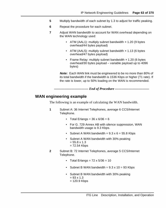
IP Network Engineering Guidelines Page 63 of 370
5 Multiply bandwidth of each subnet by 1.3 to adjust for traffic peaking.
6 Repeat the procedure for each subnet.
7 Adjust WAN bandwidth to account for WAN overhead depending on the WAN technology used:
• ATM (AAL1): multiply subnet bandwidth × 1.20 (9 bytes overhead/44 bytes payload)
• ATM (AAL5): multiply subnet bandwidth × 1.13 (6 bytes overhead/47 bytes payload)
• Frame Relay: multiply subnet bandwidth × 1.20 (6 bytes overhead/30 bytes payload – variable payload up to 4096 bytes)
Note: Each WAN link must be engineered to be no more than 80% of its total bandwidth if the bandwidth is 1536 Kbps or higher (T1 rate). If the rate is lower, up to 50% loading on the WAN is recommended.
—————————— End of Procedure ——————————
WAN engineering exampleThe following is an example of calculating the WAN bandwidth.
1 Subnet A: 36 Internet Telephones, average 6 CCS/Internet Telephone.
• Total Erlangs = 36 x 6/36 = 6
• For G. 729 Annex AB with silence suppression, WAN bandwidth usage is 9.3 Kbps.
• Subnet A WAN bandwidth = 9.3 x 6 = 55.8 Kbps
• Subnet A WAN bandwidth with 30% peaking = 55.8 x 1.3= 72.54 Kbps
2 Subnet B: 72 Internet Telephones, average 5 CCS/Internet Telephone.
• Total Erlangs = 72 x 5/36 = 10
• Subnet B WAN bandwidth = 9.3 x 10 = 93 Kbps
• Subnet B WAN bandwidth with 30% peaking = 93 x 1.3 = 120.9 Kbps
ITG Line Description, Installation, and Operation
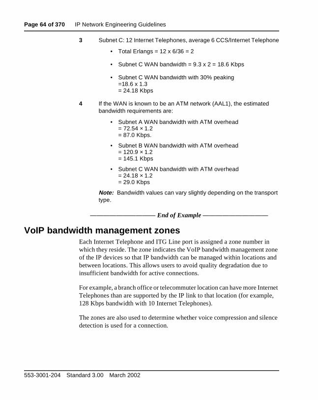
Page 64 of 370 IP Network Engineering Guidelines
3 Subnet C: 12 Internet Telephones, average 6 CCS/Internet Telephone
• Total Erlangs = 12 x 6/36 = 2
• Subnet C WAN bandwidth = 9.3 x 2 = 18.6 Kbps
• Subnet C WAN bandwidth with 30% peaking =18.6 x 1.3 = 24.18 Kbps
4 If the WAN is known to be an ATM network (AAL1), the estimated bandwidth requirements are:
• Subnet A WAN bandwidth with ATM overhead = 72.54 × 1.2= 87.0 Kbps.
• Subnet B WAN bandwidth with ATM overhead = 120.9 × 1.2 = 145.1 Kbps
• Subnet C WAN bandwidth with ATM overhead = 24.18 × 1.2 = 29.0 Kbps
Note: Bandwidth values can vary slightly depending on the transport type.
—————————— End of Example ——————————
VoIP bandwidth management zonesEach Internet Telephone and ITG Line port is assigned a zone number in which they reside. The zone indicates the VoIP bandwidth management zone of the IP devices so that IP bandwidth can be managed within locations and between locations. This allows users to avoid quality degradation due to insufficient bandwidth for active connections.
For example, a branch office or telecommuter location can have more Internet Telephones than are supported by the IP link to that location (for example, 128 Kbps bandwidth with 10 Internet Telephones).
The zones are also used to determine whether voice compression and silence detection is used for a connection.
553-3001-204 Standard 3.00 March 2002

IP Network Engineering Guidelines Page 65 of 370
Zone properties are defined in Overlay 117. Up to 256 zones can be configured. The Meridian 1 and Succession CSE 1000 use the zones for bandwidth management. New calls will be blocked when bandwidth limit is reached.
Each zone has four parameters. The prompt lists the parameters as p1, p2, p3, and p4:
• p1 - total bandwidth available for intrazone calls
• p2 - the preferred strategy for the choice of codec for intrazone calls (that is, preserve best quality or best bandwidth)
• p3 - the total bandwidth available for interzone calls
• p4 - the preferred strategy for the choice of the codec for interzone calls
If no IP voice zones are configured, zone 0 operates as a default zone with no restrictions on bandwidth usage. If no IP voice zones are configured in Overlay 117, zone 0 can be configured for IPTN in Overlay 14, and for virtual line in Overlay 11 as a default zone. However, if any additional zones are required, zone 0 must be first configured in Overlay 117 if it is referenced by any Internet Telephone or ITG Physical TNs (IPTN). If zone 0 is not configured first, then all calls in zone 0 are labeled as soon as another zone is configured in Overlay 117.
Figure 8 on page 66 shows an example of bandwidth management.
CAUTIONWhen moving an Internet Telephone, the Administrator must change the zone assignment in Overlay 11. See Administration (553-3001-311).
CAUTIONZone 0 must be configured in Overlay 117 before other zones are configured or all calls associated with zone 0 will be blocked.
ITG Line Description, Installation, and Operation
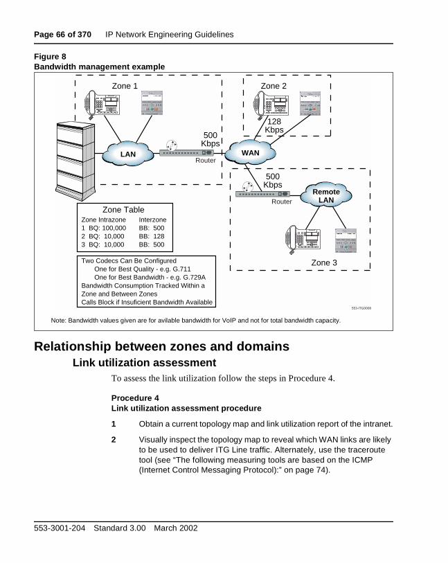
Page 66 of 370 IP Network Engineering Guidelines
Figure 8Bandwidth management example
Relationship between zones and domainsLink utilization assessment
To assess the link utilization follow the steps in Procedure 4.
Procedure 4Link utilization assessment procedure
1 Obtain a current topology map and link utilization report of the intranet.
2 Visually inspect the topology map to reveal which WAN links are likely to be used to deliver ITG Line traffic. Alternately, use the traceroute tool (see “The following measuring tools are based on the ICMP (Internet Control Messaging Protocol):” on page 74).
Note: Bandwidth values given are for avilable bandwidth for VoIP and not for total bandwidth capacity.
Zone TableZone Intrazone Interzone1 BQ: 100,000 BB: 5002 BQ: 10,000 BB: 1283 BQ: 10,000 BB: 500
Two Codecs Can Be Configured One for Best Quality - e.g. G.711 One for Best Bandwidth - e.g. G.729ABandwidth Consumption Tracked Within aZone and Between ZonesCalls Block if Insuficient Bandwidth Available
Zone 1 Zone 2
Zone 3
500Kbps
128Kbps
500Kbps
LAN WAN
RemoteLAN
553-ITG0008
Router
Router
553-3001-204 Standard 3.00 March 2002

IP Network Engineering Guidelines Page 67 of 370
3 Find out the current utilization of the WAN links. For example, the link’s use can be averaged over a week, a day, or an hour.
4 Obtain the busy period (peak hour) use of the link.
5 Also, because WAN links are Full Duplex and data services exhibit asymmetric traffic behavior, obtain the utilization of the link representing traffic flowing in the heavier direction.
6 Assess how much spare capacity is available.
Enterprise intranets are subject to capacity planning policies that ensure that capacity usage remains below some pre-determined use level.
For example, a planning policy states that the use of a 56 Kbps link during the peak hour must not exceed 50%; for a T1 link, the threshold is higher, perhaps 80%. The carrying capacity of the 56 Kbps link would therefore be 28 Kbps, and for the T1, 1.2288 Mbps. In some organizations, the thresholds can be lower than that used in this example; in the event of link failures, there needs to be spare capacity for traffic to be re-routed.
7 The difference between the current capacity, and its allowable limit, is the available VoIP capacity.
For example, a T1 link used at 48% during the peak hour, with a planning limit of 80% has an available capacity of about 492 Kbps.
—————————— End of Procedure ——————————
Estimating network loading due to ITG LineAt this point, the technician has enough information to “load” the ITG Line traffic on the intranet. The following example illustrates how this is done on an individual link. Not only must the ITG Line traffic be taken into account but also the ITG Trunk.
Example:The intranet has a topology as shown in Figure 9 on page 68, and the technician wants to predict the amount of traffic between the ITG Line node and corporate intranet. From the Calculate ITG Line traffic requirements section (see page 58) and traceroute measurements, the traffic is collected between the ITG Line node and subnet A, the ITG Line node and subnet B, and the ITG Line node and Router/Server C.
ITG Line Description, Installation, and Operation
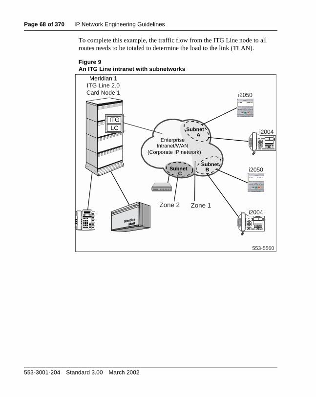
Page 68 of 370 IP Network Engineering Guidelines
To complete this example, the traffic flow from the ITG Line node to all routes needs to be totaled to determine the load to the link (TLAN).
Figure 9An ITG Line intranet with subnetworks
553-5560
Subnet A
SubnetB
Enterprise Intranet/WAN
(Corporate IP network)
SubnetC
Zone 1Zone 2i2004
i2004
Meridian 1ITG Line 2.0Card Node 1
PRIITGLC
i2050
i2050
553-3001-204 Standard 3.00 March 2002

IP Network Engineering Guidelines Page 69 of 370
Decision: Is there sufficient capacity?A link is defined as the route between the ITG Line card node and a subnet. Table 9 organizes the computations for each link, so that the available link capacity can be compared against the additional ITG Line card load. For example, on the link from the ITG Line card Node to Subnet C, there is plenty of available capacity (568 Kbps) to accommodate the additional 24 Kbps of ITG Line card traffic.
Some network management systems have network planning modules that compute network flows in the manner just described. These modules provide detailed and accurate analysis as they take into account actual node, link, and routing information. They also help the technician assess the network resilience by conducting link and node failure analysis. By simulating failures, re-loading the network, and re-computing routes, the modules indicate where the network may run out of capacity during failures.
Insufficient link capacityIf there is insufficient link capacity, consider upgrading the link's bandwidth. RTP header compression can be implemented on the WAN router if it is a narrow bandwidth WAN link (less than 1.5 Mbps).
Table 9Link Utilization Summary Example
Link Utilization (%) Available capacity (Kbps)
Incremental ITG load
Traffic (Kbps)
Sufficient capacity?End-
pointsCapacity(Kbps)
Threshold Used
ITG_Node1 - SubnetA
1536 80 75 76.8 72.5 Yes
ITG_Node1 - SubnetB
1536 80 50 460.8 120.9 Yes
ITG_Node1 - SubnetC
1536 80 48 492 24.2 Yes
ITG Line Description, Installation, and Operation

Page 70 of 370 IP Network Engineering Guidelines
Set service parametersQuality of Service (QoS) mechanism
The QoS requested from the IP network is controlled by the DiffServ Code Point (DSCP). QoS is controlled by setting the DSCP field in the IP header for both the ITG Line card and the Internet Telephone. Individual values are configurable for the voice and control DSCP values and can be configured to a number between 0 and 63 inclusive using OTM 1.2 (or later). DSCP values control per hop behavior for packet forwarding for the router.
The values are set once for each system and apply to all packets sent by the ITG Line card and the Internet Telephone.
For versions before OTM 1.1, the default value is 0. If DiffServ is implemented on the network, the IP Network Administrator should change the default value of 0 to another value. Ask the network administrator if the default values will be used in the system. The recommended configuration values are:
• voice DSCP: 46 - Expedited Forwarding (EF) per hop behavior
• control DSCP: 40 - Class Selector 5 (CS5)
Note: OTM 1.2 has 46 and 40 as the default values.
In some cases, the IP Network Administrator can set the DiffServ field at the edge of the QoS-controlled network by routers at the network edge. DiffServ can be set based on source or destination address, or port number. The ITG Line card and Internet Telephone can be configured to have RTP voice UDP port numbers in a specific range.
553-3001-204 Standard 3.00 March 2002

IP Network Engineering Guidelines Page 71 of 370
ITG Line card and Internet Telephone port numbersTable 10 lists the UDP ports used for ITG Line to Internet Telephone communications.
Table 10UDP ports used for ITG Line to Internet Telephone communications
Port usage Port number mapping
Signaling (UNIStim over RUDP link)
ITG Line port 5100 to Internet Telephone port 5000
Note: Port 5000 is fixed by the Internet Telephone.
Voice (Media) RTP:ITG Line port 5200 - 5246 (even numbers) toInternet Telephone port 5200
Note: The OTM user interface allows setting a "Voice Port" value; this sets both the Internet Telephone RTP port and the starting port for the ITG Line gateway's RTP port range. 5200 is the default, meaning the Internet Telephone uses port 5200 while the ITG Line gateway channels [0-23] use the even port numbers in the range [5200 - 5246].
RTCP:ITG Line port 5201 - 5247 (odd numbers) toInternet Telephone port 5201
Note: The RTCP port numbering is based on each channel's RTP port + 1. Therefore, the RTCP port range is dependent on the configuration for RTP port.
Registration ITG Line ports 4100 and 7300 to Internet Telephone port 5000
i2004 Internet Telephone firmware download
TFTP standard port 69
ITG Line Description, Installation, and Operation

Page 72 of 370 IP Network Engineering Guidelines
Table 11 lists the other UDP ports used by the ITG Line.
Measure intranet Quality of ServiceUtilization of the existing data network must be assessed to determine the quality of voice services it can support.
End-to-end delay and error characteristics of the intranet must be measured so that the technician can set realistic QoS expectations for intranet voice services.
The use of measuring tools requires a source node and a destination node. The source node can be a “PING” (see page 74) host on a LAN segment attached to the router intended to support the ITG Line card node. The destination node can be a remote subnet. The requirement is briefly described as follows.
Note: Make sure that the ITG network DiffServ bytes are set to their intended operational values before taking measurements.
Table 11Other UDP ports used by the ITG Line
Port usage Port number mapping
Bidirectional TPS to TPS signaling (intercard) 16543
SNTP signaling 20000 + ITG Line node number
BOOTP server on Leader 67 (standard)
BOOTP client on Followers 68 (standard)
SNMP on ELAN interface 161 (standard)
RUDP signaling with Meridian 1 core CPU on ELAN interface
1500015001
WARNINGNetwork designers must be aware of traffic calling patterns between any combination of Internet Telephones and gateway channels, and must plan the capacity of connecting elements to handle the expected traffic.
553-3001-204 Standard 3.00 March 2002

IP Network Engineering Guidelines Page 73 of 370
Criteria
• End-to-end packet delay: Packet delay is the point-to-point, one-way delay between the time a packet is sent to the time it is received at the remote end. It is comprised of delays at the ITG Line card, Internet Telephone, and the IP network. To minimize delays, the ITG Line node and Internet Telephone must be located to minimize the number of hops to the network backbone or WAN.
Note: To ensure good voice quality, an end-to-end delay of <= 50 ms is recommended on the IP network. This does not include the built-in delay of the ITG Line card and Internet Telephone.
• End-to-end packet loss: Packet loss is the percentage of packets sent that do not arrive at their destination. Transmission equipment problems, packet delay, and network congestion cause packet loss. In voice conversation, packet loss appears as gaps in the conversation. Sporadic loss of a few packets can be more tolerable than infrequent loss of a large number of packets clustered together.
Note: For high-quality voice transmission, the long-term average packet loss between the Internet Telephones and the ITG Line card TLAN interface must be < 1%, and the short-term packet loss must not exceed 5% in any 10-second interval.
Packet loss on the ELAN interface can cause:
• communication problems between the Call Server and the ITG Line cards
• lost SNMP alarms• incorrect status information on the OTM console• other signaling related problems
Note: Since the ELAN network is a Layer 2 Switched LAN, the packet loss must be zero. If packet loss is experienced, its source must be investigated and eliminated. For reliable signaling communication on the ELAN interface, the packet loss must be < 1%.
ITG Line Description, Installation, and Operation

Page 74 of 370 IP Network Engineering Guidelines
The following measuring tools are based on the ICMP (Internet Control Messaging Protocol):
• PING (sends ICMP echo requests)
• Traceroute (sends packets to unequipped port numbers and processes to create ICMP destination unavailable messages).
Both PING and traceroute are basic measuring tools that can be used to assess the ITG Line network. They are standard utilities that come with most commercial operating systems. PING is used to measure the round-trip delay of a packet and the percentage of packet loss. Traceroute breaks down delay segments of a source-destination pair and any hops in-between to accumulate measurements.
There are several third-party applications that perform data collection similar to that of PING and traceroute. In addition, these programs analyze data and plot performance charts. The use of PING and traceroute to collect data for manual analysis is labor intensive; however, they provide information as useful as the more sophisticated applications.
The following analysis use PING/traceroute data for discussion, although it is likely in most situations a third-party application will be used.
Destination TypesTo a remote subnetThis configuration involves an intranet subnet that is attached to a number of Internet Telephones, which serves as a hub for delivering voice packets between the Internet Telephone and the ITG Line network. Collect the delay measurement between the PING host and the subnet server.
Measuring end-to-end network delayThe basic tool used in ITG Line networks to measure end-to-end network delay is the PING program. PING takes a delay sample by sending an ICMP packet from the host of the PING program to a destination server, and waits for the packet to make a round trip.
553-3001-204 Standard 3.00 March 2002

IP Network Engineering Guidelines Page 75 of 370
To ensure the delay sample results are representative of the ITG_Node1:
a. Attach the PING host to a “healthy” LAN segment.
b. Attach the LAN segment to the router intended to support the ITG Line card node.
c. Choose a destination host by following the same critical guidelines as for the source host.
The size of the PING packets can be any number; the default is 60 bytes.
Sample PING output:
ITG_Node1% PING -s subnetA 60
PING subnetA (10.3.2.7): 60 data bytes
68 bytes from (10.3.2.7): icmp_seq=0 ttl=225 time=97ms
68 bytes from (10.3.2.7): icmp_seq=0 ttl=225 time=100ms
68 bytes from (10.3.2.7): icmp_seq=0 ttl=225 time=102ms
68 bytes from (10.3.2.7): icmp_seq=0 ttl=225 time=97ms
68 bytes from (10.3.2.7): icmp_seq=0 ttl=225 time=95ms
68 bytes from (10.3.2.7): icmp_seq=0 ttl=225 time=94ms
68 bytes from (10.3.2.7): icmp_seq=0 ttl=225 time=112ms
68 bytes from (10.3.2.7): icmp_seq=0 ttl=225 time=97ms
^?
--- ITG_Node1 PING Statistics ---
8 packets transmitted, 8 packets received, 0% packet loss
round-trip (ms) min/avg/max = 94/96/112
—————————— End of Procedure ——————————
Assessment of sample PING output
Note: The round-trip time (rtt) is indicated by the time field.
ITG Line Description, Installation, and Operation

Page 76 of 370 IP Network Engineering Guidelines
The rtt from the PING output varies. It is from repeated sampling of rtt that a delay characteristic of the intranet can be obtained. In order to obtain a delay distribution, the PING tool can be embedded in a script which controls the frequency of the PING probes, timestamps and stores the samples in a raw data file. The file can then be analyzed later using a spreadsheet or another application. The technician can also check whether the intranet's network management software has any delay measurement modules which can obtain a delay distribution for a specific route.
Delay characteristics vary depending on the site pair and the time-of-day. The site pair is defined as the measurement between the host ITG Line and the remote subnet (for example, ITG Line to subnet A in Figure 9 on page 68). The assessment of the intranet must include taking delay measurements for each ITG Line site pair. If there is a significant variation of traffic on the intranet, include PING samples during the intranet's peak hour. For a complete assessment of the intranet's delay characteristics, obtain PING measurements over a period of at least a week.
Measuring end-to-end packet lossThe PING program also reports whether the ICMP packet made its round trip successfully or not. Use the same PING host setup to measure end-to-end error, and in making delay measurement, use the same packet size parameter.
Multiple PING samples must be used when sampling for error rate. Packet loss rate (PLR) is the error rate statistic collected by multiple PING samples. To be statistically significant, at least 300 samples must be used. Obtaining an error distribution requires running PING over a greater period of time.
553-3001-204 Standard 3.00 March 2002

IP Network Engineering Guidelines Page 77 of 370
Recording routesThe traceroute tool records routing information for all source-destination pairs as part of the network assessment. An example of the traceroute output is shown below:
itg_node1% traceroute subnetA
traceroute to subnetA 10.3.2.7, 30 hops max, 32 byte packets
1 r6 (10.8.0.1) 1 ms 1 ms 1 ms
2 r5 (10.18.0.2) 42 ms 44 ms 38 ms
3 r4 (10.28.0.3) 78 ms 70 ms 81 ms
4 r1 (10.3.0.1) 92 ms 90 ms 101 ms
5 subnetA (10.3.2.7) 94 ms 97 ms 95 ms
The traceroute program is also used to verify whether routing in the intranet is symmetric or not for each of the source-destination pairs. This is done using the -g loose source routing option, as illustrated in the following command syntax:
itg_node1% traceroute -g subnetA itg_node1
Adjusting PING measurementsOne-way and roundtrip
The PING statistics are based on round-trip measurements, whereas the QoS metrics in the Transmission Rating model are one-way. Divide the delay and packet error PING statistics in half to ensure the comparison is valid.
Adjustment due to ITG Line processingThe PING measurements are taken from PING host to PING host. The Transmission Rating QoS metrics are from end user to end user, and include components outside the intranet. The PING statistic for delay needs to be further modified by adding 93ms to account for the processing and jitter buffer delay of the ITG Line card nodes.
Note: No adjustment needs to be made for error rates.
If the intranet measurement barely meets the round-trip QoS objectives, the technician must be aware of the possibility that the one-way QoS will not be met in one of the directions of flow. This can apply even if the flow is on a symmetric route due to asymmetric behavior of data processing services.
ITG Line Description, Installation, and Operation
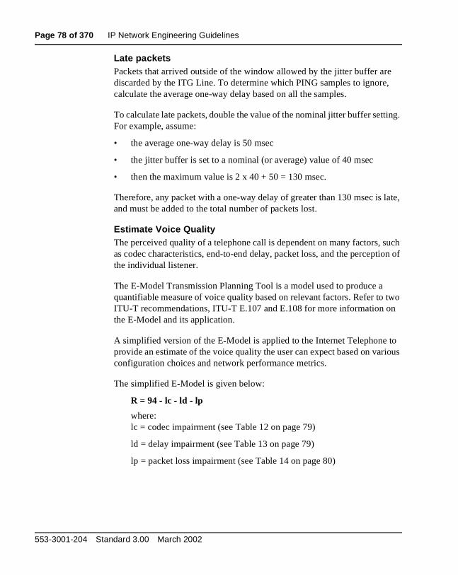
Page 78 of 370 IP Network Engineering Guidelines
Late packetsPackets that arrived outside of the window allowed by the jitter buffer are discarded by the ITG Line. To determine which PING samples to ignore, calculate the average one-way delay based on all the samples.
To calculate late packets, double the value of the nominal jitter buffer setting. For example, assume:
• the average one-way delay is 50 msec
• the jitter buffer is set to a nominal (or average) value of 40 msec
• then the maximum value is 2 x 40 + 50 = 130 msec.
Therefore, any packet with a one-way delay of greater than 130 msec is late, and must be added to the total number of packets lost.
Estimate Voice QualityThe perceived quality of a telephone call is dependent on many factors, such as codec characteristics, end-to-end delay, packet loss, and the perception of the individual listener.
The E-Model Transmission Planning Tool is a model used to produce a quantifiable measure of voice quality based on relevant factors. Refer to two ITU-T recommendations, ITU-T E.107 and E.108 for more information on the E-Model and its application.
A simplified version of the E-Model is applied to the Internet Telephone to provide an estimate of the voice quality the user can expect based on various configuration choices and network performance metrics.
The simplified E-Model is given below:
R = 94 - lc - ld - lp
where: lc = codec impairment (see Table 12 on page 79)
ld = delay impairment (see Table 13 on page 79)
lp = packet loss impairment (see Table 14 on page 80)
553-3001-204 Standard 3.00 March 2002

IP Network Engineering Guidelines Page 79 of 370
Note: This model already takes into account some characteristics of the Internet Telephone, and therefore the impairment factors are not identical to those shown in the ITU-T standards.
Refer to Table 15 on page 80 for the translation of R values into user satisfaction levels.
Table 12Impairment factors of codecs
Table 13Impairment factors due to network delay
CodecCodec Impairment (lc)(msec frames)
G.711 0
G.729A/AB 11 - 20 or 30
G.729A/AB 16 - 40 or 50
Network delay* (msec) Delay Impairment (ld)
0 -49 0
50 - 99 5
100 -149 10
150 - 199 15
200 - 249 20
250 - 299 25
* Network delay is the average one-way network delay plus jitter.
ITG Line Description, Installation, and Operation

Page 80 of 370 IP Network Engineering Guidelines
Table 14Impairment factors due to packet loss
Table 15R Value translation table
Packet loss (%) Packet Lose Impairment (lp)
0 0
1 4
2 8
4 15
8 25
R Value (lower limit)
MOS User Satisfaction
90 4.5 Very satisfied
80 4.0 Satisfied
70 3.5 Some users dissatisfied
60 3.0 Many users dissatisfied
50 2.5 Nearly all users dissatisfied
0 1 Not recommended
553-3001-204 Standard 3.00 March 2002
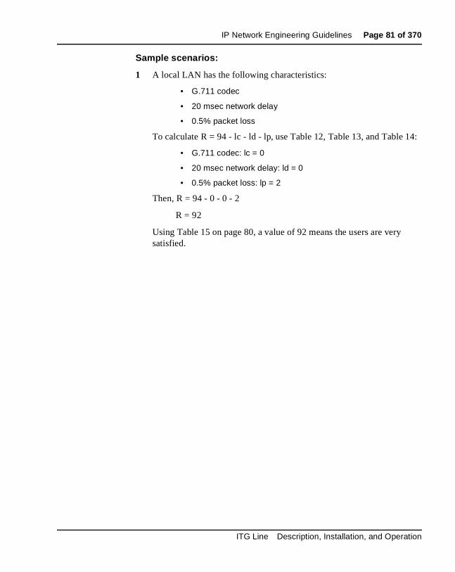
IP Network Engineering Guidelines Page 81 of 370
Sample scenarios:
1 A local LAN has the following characteristics:
• G.711 codec
• 20 msec network delay
• 0.5% packet loss
To calculate R = 94 - lc - ld - lp, use Table 12, Table 13, and Table 14:
• G.711 codec: lc = 0
• 20 msec network delay: ld = 0
• 0.5% packet loss: lp = 2
Then, R = 94 - 0 - 0 - 2
R = 92
Using Table 15 on page 80, a value of 92 means the users are very satisfied.
ITG Line Description, Installation, and Operation
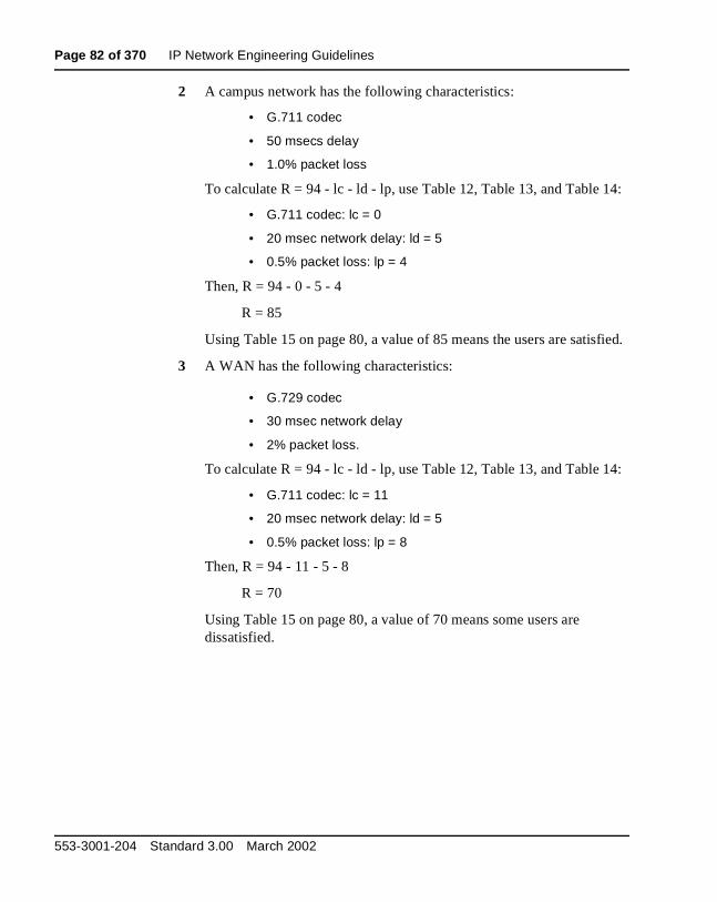
Page 82 of 370 IP Network Engineering Guidelines
2 A campus network has the following characteristics:
• G.711 codec
• 50 msecs delay
• 1.0% packet loss
To calculate R = 94 - lc - ld - lp, use Table 12, Table 13, and Table 14:
• G.711 codec: lc = 0
• 20 msec network delay: ld = 5
• 0.5% packet loss: lp = 4
Then, R = 94 - 0 - 5 - 4
R = 85
Using Table 15 on page 80, a value of 85 means the users are satisfied.
3 A WAN has the following characteristics:
• G.729 codec
• 30 msec network delay
• 2% packet loss.
To calculate R = 94 - lc - ld - lp, use Table 12, Table 13, and Table 14:
• G.711 codec: lc = 11
• 20 msec network delay: ld = 5
• 0.5% packet loss: lp = 8
Then, R = 94 - 11 - 5 - 8
R = 70
Using Table 15 on page 80, a value of 70 means some users are dissatisfied.
553-3001-204 Standard 3.00 March 2002

IP Network Engineering Guidelines Page 83 of 370
DiffServThe Differentiated Service (DiffServ) determines the priority of the packets in the IP network. The value entered depends on the equipment in the data network. The DiffServ applies to all cards in the ITG Line node and also applies to any Internet Telephones that register with this node.
Individual values are configurable for the voice and control DiffServ Code Point (DSCP) values and can be configured to a number between 0 and 63 inclusive using OTM 1.2 (and above).
The values are set once for each system and apply to all packets sent by the ITG Line card and the Internet Telephone.
For versions before OTM 1.1, the default value is 0. If DiffServ is implemented on the network, the IP Network Administrator must change the default value of 0 to another value. Ask the network administrator if the default values will be used in the system. The recommended configuration values are:
• voice DSCP: 46 - Expedited Forwarding (EF)
• control DSCP: 40 - Class Selector 5 (CS5)
Note: OTM 1.2 has 46 and 40 as the default values.
Loss and Level PlanThe ITG Line card ships with a predefined loss and level plan. The loss and level plan determines various parameters, such as transmission gain, that vary from country to country. The default loss and level plan is for the United States. The values are stored in a file on the OTM PC. You can select other countries when you configure the DSP Profile settings in the OTM ITG Line Internet Telephone application.
Echo cancellerITG Line supports echo canceller tail lengths of 8, 16, and 32 msec. The default in OTM is the maximum of 32 msec. It is recommended that the maximum echo canceller tail length is used.
ITG Line Description, Installation, and Operation
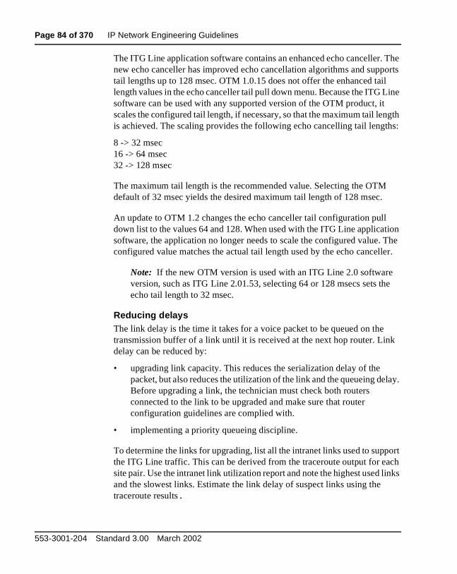
Page 84 of 370 IP Network Engineering Guidelines
The ITG Line application software contains an enhanced echo canceller. The new echo canceller has improved echo cancellation algorithms and supports tail lengths up to 128 msec. OTM 1.0.15 does not offer the enhanced tail length values in the echo canceller tail pull down menu. Because the ITG Line software can be used with any supported version of the OTM product, it scales the configured tail length, if necessary, so that the maximum tail length is achieved. The scaling provides the following echo cancelling tail lengths:
8 -> 32 msec16 -> 64 msec32 -> 128 msec
The maximum tail length is the recommended value. Selecting the OTM default of 32 msec yields the desired maximum tail length of 128 msec.
An update to OTM 1.2 changes the echo canceller tail configuration pull down list to the values 64 and 128. When used with the ITG Line application software, the application no longer needs to scale the configured value. The configured value matches the actual tail length used by the echo canceller.
Note: If the new OTM version is used with an ITG Line 2.0 software version, such as ITG Line 2.01.53, selecting 64 or 128 msecs sets the echo tail length to 32 msec.
Reducing delaysThe link delay is the time it takes for a voice packet to be queued on the transmission buffer of a link until it is received at the next hop router. Link delay can be reduced by:
• upgrading link capacity. This reduces the serialization delay of the packet, but also reduces the utilization of the link and the queueing delay. Before upgrading a link, the technician must check both routers connected to the link to be upgraded and make sure that router configuration guidelines are complied with.
• implementing a priority queueing discipline.
To determine the links for upgrading, list all the intranet links used to support the ITG Line traffic. This can be derived from the traceroute output for each site pair. Use the intranet link utilization report and note the highest used links and the slowest links. Estimate the link delay of suspect links using the traceroute results.
553-3001-204 Standard 3.00 March 2002

IP Network Engineering Guidelines Page 85 of 370
Example: A 256 Kbps link from router1 to router 2 has a high utilization. The following is a traceroute output that traverses this link:
ITG_Node1% traceroute SubnetA
traceroute to SubnetA (10.3.2.7), 30 hops max, 32 byte packets
router1 (10.8.0.1) 1 ms 1 ms 1 ms
router2 (10.18.0.2) 42 ms 44 ms 38 ms
router3 (10.28.0.3) 78 ms 70 ms 81 ms
router4 (10.3.0.1) 92 ms 90 ms 101 ms
SubnetA (10.3.2.7) 94 ms 97 ms 95 ms
The average rtt time on the example link is about 40 ms; the one-way link delay is about 20 ms, of which the circuit transmission and serialization delay are just a few milliseconds. Most of this link's delay is due to queueing.
Reducing hop countThe ITG Line card nodes must be connected to the intranet to minimize the number of router hops between the ITG Line card and the Internet Telephone. This will reduce the fixed and variable IP packet delay, and improve the Voice over IP Quality of Service. It is recommended that no more than one card utilize a particular 10BaseT LAN collision domain.
Note: In a passive Ethernet hub, all ports on the hub share one 10Mbps collision domain; in a switched Ethernet hub, each port has its own collision domain.
The ITG Line card node and the TLAN router should be placed as close to the WAN backbone as possible in order to:
• minimize the number of router hops.
• segregate constant bit-rate VoIP traffic from bursty LAN traffic.
• simplify the end-to-end QoS engineering for packet delay, jitter, and packet loss.
If an access router separates the ITG Line card node from the WAN router, there must be a high-speed link (for example, Fast Ethernet, FDDI, SONET, OC-3c, ATM STS-3c) between the access router and the WAN backbone router.
ITG Line Description, Installation, and Operation
Page 86 of 370 IP Network Engineering Guidelines
Reducing packet errorsPacket errors in intranets are generally correlated with congestion somewhere in the network. Bottleneck links occur where the packet errors are high because packets get dropped when they arrive faster than the link can transmit them. When highly used links are upgraded, the sources of packet errors on a particular flow must be removed. A reduction in hop count also reduces the opportunities for routers and links to drop packets.
Other causes of packet errors, not related to queueing delay, are as follows:
• Poor link quality–the underlying circuit has transmission problems, high line error rates, or subject to frequent outages. The circuit is provisioned on top of other services, such as X.25, frame relay, or ATM. Check with the service provider for resolution.
• Overloaded CPU–this is another commonly-monitored statistic collected by network management systems. If a router is overloaded, it means that the router is constantly performing processing-intensive tasks, which impedes the router from forwarding packets. Find out what the threshold CPU utilization level is, and check if any suspect router conforms to the threshold. The router has to be re-configured or upgraded.
• Saturation–routers can also be overworked when there are too many high capacity and high traffic links configured on it. Ensure that routers are dimensioned according to vendor guidelines.
• LAN saturation–packets are dropped on under-engineered or faulty LAN segments.
• Jitter buffer too small–packets that arrive at the destination ITG, but are too late to be placed in the jitter buffer, are essentially loss packets.
553-3001-204 Standard 3.00 March 2002

IP Network Engineering Guidelines Page 87 of 370
Adjusting jitter buffer sizeThe jitter buffer parameters directly affect the end-to-end delay. Lowering the voice playout settings decreases one-way delay, but this comes at the expense of giving less waiting time for voice packets that arrive late.
The jitter buffer setting is configured on the voice gateway channels of the ITG Line card and are sent out to the Internet Telephones. The jitter buffer size is set when you configure the DSP Profiles in the ITG IP Phones application (see Figure 15 on page 144). The jitter buffer is statically configured and is the same for all devices in the network. The jitter buffer size range is 0-200 milliseconds. The default jitter buffer value is 50 milliseconds. However, the jitter buffer setting that is actually used on the ITG Line card is a multiple of the codec frame size. The setting is automatically adjusted to be greater than or equal to the jitter buffer value set in the DSP Profile tab. As each call is set up, the jitter buffer for each device is set to the nearest whole number increment of the selected codec frame size.
For example, if the jitter buffer is configured as the default 50 msec in the DSP Profiles, but a 20 msec codec is used, the jitter buffer will be set to 60 msec, which is the nearest whole number increment.
50 msec / 20 msec = 2.52.5 rounded up to the nearest whole number increment is 3.3 x 20 msec = 60 msec
If the jitter buffer is configured as zero, the depth of the jitter buffer is set to the smallest value the device can support. In practice, the optimum depth of the jitter queue is different for each call. For telephones that are on a local LAN connection, a short jitter queue is desirable to minimize delay. For telephones that are several router hops away, a longer jitter queue is required.
Lowering the jitter buffer size decreases the one-way delay of voice packets; however, setting the jitter buffer size too small will cause unnecessary packet discard. Discarded packets result in poorer speech quality and can be heard as clicks or choppy speech.
ITG Line Description, Installation, and Operation
Page 88 of 370 IP Network Engineering Guidelines
If the technician decides to discard packets, to downsize the jitter buffer, the technician must do the following:
• Check the delay variation statistics. Obtain the one-way delay distributions originating from all source ITG Line sites.
• Compute the standard deviation of one-way delay for every flow. Some traffic sources with few hop counts yield small delay variations, but it is the flows that produce great delay variations that should be used to determine whether it is acceptable to resize the jitter buffer.
• Compute the standard deviation (σ) of one-way delay for that flow. Do not set the set the jitter buffer size smaller than 2s.
Codec selectionTo ensure optimal voice quality, minimize the number of compression and decompression stages and wherever bandwidth permits, use G.711 codec.
There is a potential to degrade the voice quality if codecs are cascaded. This can occur when there are multiple compression and decompression stages on a voice call. The more IP links used in a call, the more delay is added, and therefore the greater the impact on the voice quality.
The following is a list of applications and devices which can impact voice quality, if you use a compression codec such as G.729A:
• Voice mail introduces another stage of compression and decompression. For example, Nortel Networks CallPilot
• Conferences can double the number of IP links
• ITG Trunks can add additional stages of compression and decompression
Post-installation network measurementsThe design process is continual, even after implementation of the ITG network and commissioning of voice services over the network. Network changes – in actual ITG traffic, general intranet traffic patterns, network policies, network topology, user expectations, and networking technology – can render a design obsolete or non-compliant with QoS objectives. The design needs to be reviewed periodically against prevailing network conditions and traffic patterns.
553-3001-204 Standard 3.00 March 2002
IP Network Engineering Guidelines Page 89 of 370
It is assumed that the customer’s organization already has processes to monitor, analyze, and re-design both the Meridian 1 and Succession CSE 1000 network and the corporate intranet to maintain internal QoS standards. When operating an ITG network, additional processes must be developed to:
• collect, analyze, and forecast ITG traffic patterns
• monitor operational measurements (see below)
• implement changes in the ITG and intranet when planning thresholds are reached
By instituting these new processes, the ITG network can be managed to ensure that desired QoS objectives are met.
ITG Operational Measurement (OM)The ITG Line card collects operational measurements from the Internet Telephones and DSP channels and saves the information to a log file every 60 minutes. The operational measurements include:
• Internet Telephone Registration Attempted Count
• Internet Telephone Registration Confirmed Count
• Internet Telephone Unregistration Count
• Internet Telephone Audio Stream Set Up Count
• Internet Telephone Average Jitter (msec)
• Internet Telephone Maximum Jitter (msec)
• Internet Telephone Packets Lost/Late (%)
• Internet Telephone Total Voice Time (minutes and seconds)
• Gateway Channel Audio Stream Set Up Count
• Gateway Channel Average Jitter (msec)
• Gateway Channel Maximum Jitter (msec)
• Gateway Channel Packets Lost/Late (%)
• Gateway Channel Total Voice Time (minutes and seconds)
ITG Line Description, Installation, and Operation

Page 90 of 370 IP Network Engineering Guidelines
OM Report descriptionThe OM log file is a comma-separated (.csv) file stored on the OTM server. Using OTM you can run an adhoc report or schedule a regular report. A new file is created for each month of the year in which OM data is collected. It can be read directly or imported to a spreadsheet application for post-processing and report generation. Collect these OM reports and store them for analysis. At the end of each month, identify the hours with the highest packet lost/late statistics and standard deviation statistics generated. Compare the data to target network QoS objectives.
Declines in QoS can be observed through the comparison of QoS between last period and current period. A consistent inferior measurement of QoS compared with the objective triggers an alarm. The customer must take steps to strengthen the performance of the route.
The card creates a new log file each day. Files are automatically deleted after seven days.
ITG Line ELAN and TLAN configurationA subnet is defined as a remote network serving a collection of Internet Telephones, which is represented by a server or router communicating with the ITG processor for VoIP service (see Figure 9 on page 68).
General requirements
• no foreign broadcast coming from other subnets
• no BootP relay agent requirement (only on ELAN router interface)
• no Network Address Translation (NAT) between Internet Telephone and ITG Line Node
553-3001-204 Standard 3.00 March 2002

IP Network Engineering Guidelines Page 91 of 370
Separate subnet configuration
Each ITG Line card has two Ethernet ports, one for the Telephony LAN (TLAN) and one for the Embedded LAN (ELAN). The advantages of this configuration are:
• optimization of VoIP performance on the LAN segment by segregating it from ELAN traffic and connecting the TLAN as close as possible to the WAN router.
• making the amount of traffic on the TLAN more predictable for QoS engineering.
• enhanced network access security when the ELAN and customer's enterprise network (C-LAN) are separate or connected through a fire-wall router:
— allows placement of the modem router on the isolated ELAN, protecting the C-LAN from unauthorized modem router accesses
— protects the Meridian 1/Succession CSE 1000 ELAN from unauthorized access from the C-LAN
ELAN and TLAN Half and Full Duplex operationThe ELAN on the ITG Line card 2.2 operates at Half Duplex only and is limited to 10BaseT operation due to filtering on the Meridian 1 Option 11C back planes.
The TLAN on ITG Line card 2.2 operates at Half Duplex or Full Duplex and can run at 10BaseT or 100BaseT.
CAUTIONDue to backwards compatibility, the user interface permits you to choose whether or not to use separate subnets. It is, however, mandatory to use separate subnets.
ITG Line Description, Installation, and Operation
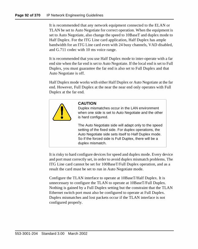
Page 92 of 370 IP Network Engineering Guidelines
It is recommended that any network equipment connected to the ELAN or TLAN be set to Auto Negotiate for correct operation. When the equipment is set to Auto Negotiate, also change the speed to 10BaseT and duplex mode to Half Duplex. For the ITG Line card application, Half Duplex has ample bandwidth for an ITG Line card even with 24 busy channels, VAD disabled, and G.711 codec with 10 ms voice range.
It is recommended that you use Half Duplex mode to inter-operate with a far end site when the far end is set to Auto Negotiate. If the local end is set to Full Duplex, you must guarantee the far end is also set to Full Duplex and that Auto Negotiate is off.
Half Duplex mode works with either Half Duplex or Auto Negotiate at the far end. However, Full Duplex at the near the near end only operates with Full Duplex at the far end.
It is risky to hard configure devices for speed and duplex mode. Every device and port must correctly set, in order to avoid duplex mismatch problems. The ITG Line card cannot be set for 100BaseT/Full Duplex operation, and as a result the card must be set to run in Auto Negotiate mode.
Configure the TLAN interface to operate at 10BaseT/Half Duplex. It is unnecessary to configure the TLAN to operate at 10BaseT/Full Duplex. Nothing is gained by a Full Duplex setting but the constraint that the TLAN Ethernet switch port must also be configured to operate at Full Duplex. Duplex mismatches and lost packets occur if the TLAN interface is not configured properly.
CAUTIONDuplex mismatches occur in the LAN environment when one side is set to Auto Negotiate and the other is hard configured.
The Auto Negotiate side will adapt only to the speed setting of the fixed side. For duplex operations, the Auto Negotiate side sets itself to Half Duplex mode. So if the forced side is Full Duplex, there will be a duplex mismatch.
553-3001-204 Standard 3.00 March 2002
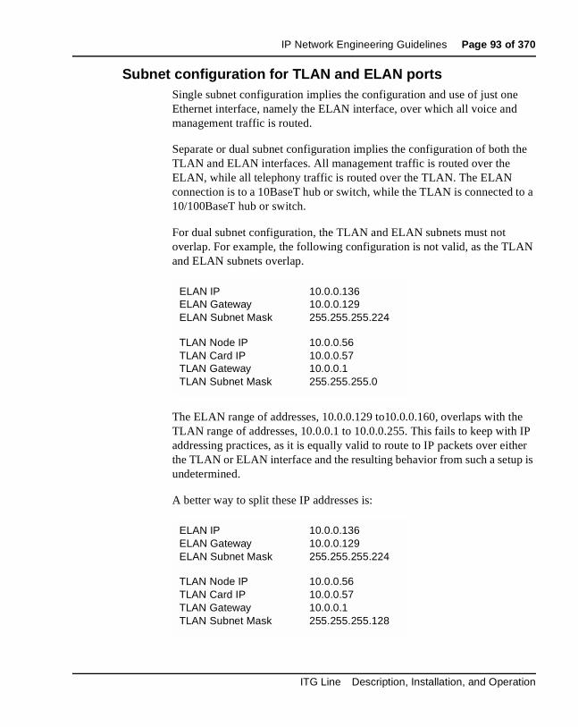
IP Network Engineering Guidelines Page 93 of 370
Subnet configuration for TLAN and ELAN portsSingle subnet configuration implies the configuration and use of just one Ethernet interface, namely the ELAN interface, over which all voice and management traffic is routed.
Separate or dual subnet configuration implies the configuration of both the TLAN and ELAN interfaces. All management traffic is routed over the ELAN, while all telephony traffic is routed over the TLAN. The ELAN connection is to a 10BaseT hub or switch, while the TLAN is connected to a 10/100BaseT hub or switch.
For dual subnet configuration, the TLAN and ELAN subnets must not overlap. For example, the following configuration is not valid, as the TLAN and ELAN subnets overlap.
The ELAN range of addresses, 10.0.0.129 to10.0.0.160, overlaps with the TLAN range of addresses, 10.0.0.1 to 10.0.0.255. This fails to keep with IP addressing practices, as it is equally valid to route to IP packets over either the TLAN or ELAN interface and the resulting behavior from such a setup is undetermined.
A better way to split these IP addresses is:
ELAN IPELAN GatewayELAN Subnet Mask
10.0.0.13610.0.0.129255.255.255.224
TLAN Node IPTLAN Card IPTLAN GatewayTLAN Subnet Mask
10.0.0.5610.0.0.5710.0.0.1255.255.255.0
ELAN IPELAN GatewayELAN Subnet Mask
10.0.0.13610.0.0.129255.255.255.224
TLAN Node IPTLAN Card IPTLAN GatewayTLAN Subnet Mask
10.0.0.5610.0.0.5710.0.0.1255.255.255.128
ITG Line Description, Installation, and Operation
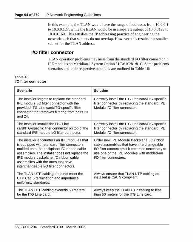
Page 94 of 370 IP Network Engineering Guidelines
In this example, the TLAN would have the range of addresses from 10.0.0.1 to 10.0.0.127, while the ELAN would be in a separate subnet of 10.0.0129 to 10.0.0.160. This satisfies the IP addressing practice of engineering the network such that subnets do not overlap. However, this results in a smaller subnet for the TLAN address.
I/O filter connectorTLAN operation problems may arise from the standard I/O filter connector in IPE modules on Meridian 1 System Option 51C/61C/81/81C. Some problems scenarios and their respective solutions are outlined in Table 16:
Table 16I/O filter connector
Scenario Solution
The installer forgets to replace the standard IPE module I/O filter connector with the provided ITG Line card/ITG-specific filter connector that removes filtering from pairs 23 and 24.
Correctly install the ITG Line card/ITG-specific filter connector by replacing the standard IPE Module I/O filter connector.
The installer installs the ITG Line card/ITG-specific filter connector on top of the standard IPE module I/O filter connector.
Correctly install the ITG Line card/ITG-specific filter connector by replacing the standard IPE Module I/O filter connector.
The installer encounters an IPE modules that is equipped with standard filter connectors molded onto the backplane I/O ribbon cable assemblies. The installer does not replace the IPE module backplane I/O ribbon cable assemblies with the ones that have interchangeable I/O filter connectors.
Order new IPE Module Backplane I/O ribbon cable assemblies that have interchangeable I/O filter connectors if it becomes necessary to use one of the IPE Modules with molded-on I/O filter connectors.
The TLAN UTP cabling does not meet the UTP Cat. 5 termination and impedance uniformity standards.
Always ensure that TLAN UTP cabling as installed is Cat. 5 compliant.
The TLAN UTP cabling exceeds 50 meters for the ITG Line card.
Always keep the TLAN UTP cabling to less than 50 meters for the ITG Line card.
553-3001-204 Standard 3.00 March 2002

Page 95 of 370
102
Installation and configuration summaryContents
This section contains information on the following topics:
Overview . . . . . . . . . . . . . . . . . . . . . . . . . . . . . . . . . . . . . . . . . . . . . . . . 95
Before you begin . . . . . . . . . . . . . . . . . . . . . . . . . . . . . . . . . . . . . . . . . . 96
Installation procedure summary . . . . . . . . . . . . . . . . . . . . . . . . . . . . . . 97Summary of steps . . . . . . . . . . . . . . . . . . . . . . . . . . . . . . . . . . . . . . . 97
ITG Line card installation summary sheet . . . . . . . . . . . . . . . . . . . . . . 100
Internet Telephone configuration data summary sheet . . . . . . . . . . . . 102
OverviewThis chapter provides a summary of the procedures required to install a new Meridian 1 and Succession Communication Server for Enterprise 1000 ITG Line card node, add cards to the node, install the cards, transmit data to the cards, and install the Internet Telephone. It also includes information on what you need before beginning the installation procedures.
Be sure to read the Engineering guidelines section before you install an ITG Line node.
ITG Line Description, Installation, and Operation

Page 96 of 370 Installation and configuration summary
Before you begin1 Ensure that your system meets the following minimum requirements:
• Meridian 1 Release 25.40 (or later), or
• Succession CSE 1000 Release 1.1 (or later).
Note: These system requirements are needed to use the i2050 Software Phone.
2 Upgrade the Meridian 1 or Succession CSE 1000 keycode to expand the ISM system limit to support the number of Internet Telephones you plan to install. Refer to Maintenance (553-3001-511) to use:
• Overlay 22 command SLT to determine your Internet Telephone limit on the system.
• Overlay 146 to expand the ISM parameters (if required).
3 Verify that you have the Optivity Telephone Manager (OTM) version 1.2 (or later).
a. Check the Meridian 1 and Succession CSE 1000 ESD web site to determine the latest software version and required patches (PEPs).
Refer to Procedure 17, “Verify card software and i2004 Internet Telephone firmware” on page 157.
b. Upgrade to the latest OTM version if necessary.
Refer to “OTM setup to manage ITG Line nodes” on page 181 for further details.
4 Create site name, system name, and customer number in the OTM Navigator. Specify the correct Meridian 1 and Succession CSE 1000 system type in order for OTM ITG IP Phones application to prompt for correct TN format.
5 Provision the IP network to support ITG Line node and Internet Telephones.
a. Choose the Internet Telephone DHCP mode: Full, Partial, or None (static IP address). For Full DHCP mode, refer to “Configuring the DHCP server to support Full DHCP mode” on page 107.
553-3001-204 Standard 3.00 March 2002
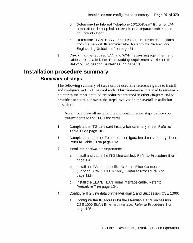
Installation and configuration summary Page 97 of 370
b. Determine the Internet Telephone 10/100BaseT Ethernet LAN connection: desktop hub or switch, or a separate cable to the equipment closet.
c. Determine TLAN, ELAN IP address and Ethernet connections from the network IP administrator. Refer to the “IP Network Engineering Guidelines” on page 51.
6 Check that the required LAN and WAN networking equipment and cables are installed. For IP networking requirements, refer to “IP Network Engineering Guidelines” on page 51.
Installation procedure summarySummary of steps
The following summary of steps can be used as a reference guide to install and configure an ITG Line card node. This summary is intended to serve as a pointer to the more detailed procedures contained in other chapters and to provide a sequential flow to the steps involved in the overall installation procedure.
Note: Complete all installation and configuration steps before you transmit data to the ITG Line cards.
1 Complete the ITG Line card installation summary sheet. Refer to Table 17 on page 101.
2 Complete the Internet Telephone configuration data summary sheet. Refer to Table 18 on page 102.
3 Install the hardware components:
a. Install and cable the ITG Line card(s). Refer to Procedure 5 on page 120.
b. Install an ITG Line-specific I/O Panel Filter Connector (Option 51C/61C/81/81C only). Refer to Procedure 6 on page 122.
c. Install the ELAN, TLAN serial interface cable. Refer to Procedure 7 on page 124.
4 Configure ITG Line data on the Meridian 1 and Succession CSE 1000:
a. Configure the IP address for the Meridian 1 and Succession CSE 1000 ELAN Ethernet interface. Refer to Procedure 8 on page 126.
ITG Line Description, Installation, and Operation

Page 98 of 370 Installation and configuration summary
b. Configure VoIP bandwidth management zones. Refer to page 127.
c. Configure ITG physical TNs. Refer to page 129.
d. Configure virtual superloops. Refer to page 129.
e. Configure Option 11C/11C-Mini mapping of virtual superloops. Refer to page 131.
f. Configure Internet Telephone Meridian 1 and Succession CSE 1000 features. Refer to page 132.
5 Configure ITG Line data on OTM:
a. Manually add an ITG Line node. Refer to Procedure 9 on page 136.
b. Configure ITG Line card properties. Refer to Procedure 10 on page 140.
c. Configure DSP Profile data. Refer to Procedure 11 on page 142.
d. Configure Meridian 1 and Succession CSE 1000 Call Server ELAN IP (Active ELNK) address and TLAN Voice port on ITG Line card. Refer to Procedure 12 on page 145.
e. Configure SNMP traps. Refer to Procedure 13 on page 147.
6 Transmit ITG Line card configuration data from OTM to the ITG Line cards:
a. Set Leader 0 IP Address. Refer to Procedure 14 on page 150.
b. Transmit node and card properties to Leader 0. Refer to Procedure 15 on page 152.
c. Transmit card properties to all cards in the node. Refer to Procedure 16 on page 154.
7 Upgrade card software and i2004 Internet Telephone firmware:
a. Verify card software and i2004 Internet Telephone firmware release. Refer to Procedure 17 on page 157.
b. Determine latest software and firmware versions from Meridian 1 and Succession CSE 1000 Electronic Software Documentation (ESD) web site. Refer to Procedure 17 on page 157.
c. Upgrade ITG Line card software (if required). Refer to Procedure 18 on page 160.
553-3001-204 Standard 3.00 March 2002

Installation and configuration summary Page 99 of 370
d. Upgrade i2004 Internet telephone firmware (if required). Refer to Procedure 19 on page 162.
8 Configure OTM alarm notification feature to receive ITG Line SNMP traps. Refer to Procedure 20 on page 167.
9 Assemble and install an Internet Telephone. Refer to the Internet Terminals: Description (553-3001-217).
10 Configure the SNMP Community Names access. Refer to Procedure 21 on page 173.
11 Configure the ITG Command Line Interface (ITGL>) Shell password. Refer to Procedure 22 on page 175.
12 Configure the Internet Telephone Installer Passwords.
a. Enable and set the administrative Internet Telephone Installer Password. Refer to Procedure 23 on page 177.
b. If needed, enable and set a temporary Internet Telephone Installer Password. Refer to Procedure 24 on page 179.
—————————— End of Procedure ——————————
ITG Line Description, Installation, and Operation

Page 100 of 370 Installation and configuration summary
ITG Line card installation summary sheetNortel Networks recommends that you complete an ITG Line card installation summary sheet (Table 17 on page 101) as you unpack, inventory, and provision the cards. IP address information will normally be supplied by the customer’s IP Network Administrator.
In order to complete the installation summary sheet you need to know:
• the MAC address. This is the motherboard Ethernet address on the ITG Line card faceplate sticker (for example 00:60:38:01:12:77).
• the ELAN Management IP address of the motherboard Ethernet interface used to perform management through OTM and to communicate with the Meridian 1 and Succession CSE 1000.
• the TLAN Node IP address for the ITG Line node.
• the TLAN card IP address of the voice interface on each card.
• the IP address of the active ELNK Ethernet interface on the Meridian 1 and Succession CSE 1000 core.
Nortel Networks recommends that you complete an Internet Telephone configuration data summary sheet (Table 18 on page 102) as you install and configure Internet Telephones.
553-3001-204 Standard 3.00 March 2002

Installation and configuration summary Page 101 of 370
Table 17ITG Line card installation summary sheet
Site________________ Meridian 1 or Succession CSE 1000 system___________________Meridian 1 and Succession CSE 1000 customer________________________Node ID (Number)________________________TLAN Node IP address________________________Meridian 1 and Succession CSE 1000 active ELNK IP address_______________________SNMP Manager List IP addresses________________________TLAN gateway (router) IP address________________________TLAN subnet mask________________________ELAN gateway (router) IP address________________________ELAN subnet mask__________________________
TNELAN
Management MAC address
ELAN Management IP
address
TLAN (Voice)Card IP address
Card role
leader
follower(OTM: Leader1)
follower
follower
follower
follower
follower
follower
follower
follower
follower
follower
ITG Line Description, Installation, and Operation

Page 102 of 370 Installation and configuration summary
Internet Telephone configuration data summary sheet
Table 18Internet Telephone configuration data summary sheet
No DHCP
Partial DHCP
Connect server IP address*
Node# VTN
Full DHCP
IP address
subnet mask
Gateway IP
addressDN
User Name
User Location
*Connect server IP address is the Node IP address of the ITG Line node.
553-3001-204 Standard 3.00 March 2002
Page 103 of 370
116
Configuration of the DHCP server Contents
This section contains information on the following topics:
Overview . . . . . . . . . . . . . . . . . . . . . . . . . . . . . . . . . . . . . . . . . . . . . . . . 103
i2004 Internet Telephone and i2050 Software Phone . . . . . . . . . . . . . . 104Partial DHCP mode . . . . . . . . . . . . . . . . . . . . . . . . . . . . . . . . . . . . . 104Full DHCP mode . . . . . . . . . . . . . . . . . . . . . . . . . . . . . . . . . . . . . . . 105ITG Line card . . . . . . . . . . . . . . . . . . . . . . . . . . . . . . . . . . . . . . . . . . 106
Configuring the DHCP server to support Full DHCP mode . . . . . . . . . 107Internet Telephone class identifier . . . . . . . . . . . . . . . . . . . . . . . . . . 107Requested Network Configuration Parameters . . . . . . . . . . . . . . . . 108Format for Nortel Networks Internet Telephone DHCP Class Identifier Option . . . . . . . . . . . . . . . . . . . . . . . . . . . . . . . . . . . 110Format for Nortel Networks Internet Telephone DHCP Encapsulated Vendor Specific Option . . . . . . . . . . . . . . . . . . . . . . . 110Format for Nortel Networks Internet Telephone DHCP Site Specific Option . . . . . . . . . . . . . . . . . . . . . . . . . . . . . . . . . . . . . 114
OverviewThis chapter provides general guidelines to configure a host with a Dynamic Host Configuration Protocol (DHCP) server to support the i2004 Internet Telephone and i2050 Software Phone.
ITG Line Description, Installation, and Operation
Page 104 of 370 Configuration of the DHCP server
Note 1: This chapter assumes that you are familiar with RFC 2131 “Dynamic Host Configuration Protocol”, RFC 1533 “DHCP Options and BOOTP Vendor Extensions”, and the Help manual for the DHCP server on your host. A convenient source for RFCs is http://www.ietf.org/
Note 2: For a general overview of DHCP server technology, refer to Appendix E: “DHCP Supplementary Information” on page 325.
Note 3: For DHCP server setup and configuration information, refer to Appendix F: “Setup and Configuration of DHCP Servers” on page 335.
i2004 Internet Telephone and i2050 Software PhoneThe i2004 Internet Telephone and the i2050 Software Phone are Voice-over Internet Protocol (VoIP) telephones, which function as a terminal to the Meridian 1 and Succession Communication Server for Enterprise 1000. The Internet Telephone encodes voice as binary data and packetizes the data for transmission over an IP Network to the ITG Line card or to another Internet Telephone.
The Nortel Networks Internet Telephone can act as a DHCP client in one of two modes:
• Partial DHCP mode
• Full DHCP mode
Partial DHCP modeWhen the Internet Telephone is configured to operate in partial DHCP mode, the DHCP server needs no special configuration to support Internet Telephones. The Internet Telephone receives the following network configuration parameters from the DHCP server:
• IP address configuration for the Internet Telephone
• Subnet mask for the Internet Telephone IP address
• Default gateway for the Internet Telephone LAN segment
553-3001-204 Standard 3.00 March 2002
Configuration of the DHCP server Page 105 of 370
Full DHCP modeIn full DHCP mode, the DHCP server requires special configuration. The Internet Telephone obtains network configuration parameters and connect server configuration parameters from specially configured DHCP server.
The following configuration parameters are provided for the primary and secondary connect servers:
• Connect server IP address. For ITG Line, the connect server IP address is the ITG Line node IP address.
• A port number of 4100.
• A command value of 1, that identifies the request to the connect server as originating from an Internet Telephone.
• A retry count typically equal to 10.
All the configuration parameters for the Internet Telephone can be entered manually. Each Internet Telephone requires the network configuration parameters, connect server parameters, ITG Line node ID, and Virtual TN. If there are a number of Internet Telephones to configure, manual configuration is time consuming and error prone.
Using Full or Partial DHCP to configure the Internet Telephones automatically is more efficient and flexible. This ensures that current information is used.
Note 1: The ITG Line node ID and Virtual TN must always be configured manually even in Full DHCP mode.
Note 2: In Partial DHCP mode the connect server parameters must be entered manually as well as the node ID and Virtual TN.
ITG Line Description, Installation, and Operation
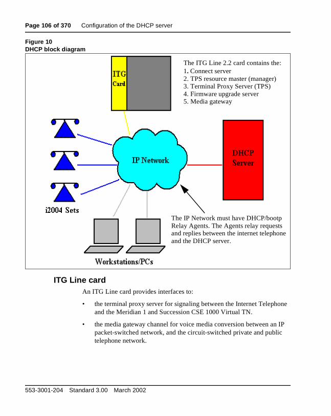
Page 106 of 370 Configuration of the DHCP server
Figure 10DHCP block diagram
ITG Line cardAn ITG Line card provides interfaces to:
• the terminal proxy server for signaling between the Internet Telephone and the Meridian 1 and Succession CSE 1000 Virtual TN.
• the media gateway channel for voice media conversion between an IP packet-switched network, and the circuit-switched private and public telephone network.
The ITG Line 2.2 card contains the:1. Connect server 2. TPS resource master (manager)3. Terminal Proxy Server (TPS)4. Firmware upgrade server5. Media gateway
The IP Network must have DHCP/bootp Relay Agents. The Agents relay requests and replies between the internet telephoneand the DHCP server.
553-3001-204 Standard 3.00 March 2002

Configuration of the DHCP server Page 107 of 370
During start-up, the Internet Telephone registers itself with the terminal proxy server on the ITG Line card and also registers the Virtual TN with the configuration parameters on the Meridian 1 and Succession CSE 1000. The media gateway channel provides an interface between the packet switched IP network and the circuit switched network of the Meridian 1 and Succession CSE 1000.
Configuring the DHCP server to support Full DHCP modeThe DHCP capability feature of the Internet Telephone, enables the telephone to receive network configuration parameters and specific connect server parameters. This section describes the Internet Telephone's unique class identifier and requested network configuration and connect server parameters for automatic configuration.
Internet Telephone class identifierThe Internet Telephone is designed with a unique class identifier that the DHCP server can use to identify it. All Nortel Networks Internet Telephones use the same text string, "Nortel-i2004-A" or "Nortel-i2050-A", to identify themselves. The ASCII string is sent inside the Class Identifier option of the Internet Telephone's DHCP messages.
The DHCP server also includes this string in its responses to the Internet Telephone DHCP client. This makes it possible to notify the Internet Telephone that the server is Internet Telephone-aware, and that it is safe to accept the server's offer. This string appears in the beginning of a list of specific ITG Line card information that the Internet Telephone DHCP client requests.
When the DHCP server has been configured to recognize the Internet Telephone as a special class, the DHCP server can treat the Internet Telephone differently than other DHCP clients. DHCP host configuration parameters can then be grouped by class and only information relevant to the Internet Telephone DHCP client, such as the connect server parameters, is supplied.
Also, the administrator can design the network according to the client's class, if necessary, making maintenance easier. Depending on the capabilities and limitations of the DHCP server used and the design of the network, some of these advanced functions may not be available.
ITG Line Description, Installation, and Operation

Page 108 of 370 Configuration of the DHCP server
Requested Network Configuration ParametersNortel Networks Internet Telephones, using Full DHCP mode, have the ability to be configured automatically by an Internet Telephone-aware DHCP server by requesting a list of connect server configuration parameters. The Internet Telephone uses DHCP, an industry standard protocol, to request and receive the information.
The Internet Telephones operating in Partial DHCP mode can receive an IP address from any DHCP server. In Full DHCP mode, the server must be configured to respond to the request for the vendor specific encapsulated options.
Table 19 lists the network configuration parameters requested by the Internet Telephone in the Parameter Request List option (Option Code 55) in the DHCPDISCOVER and DHCPREQUEST messages. The DHCPOFFER and the DHCPACK reply messages from the DHCP server must contain the options in Table 19.
Table 19Internet telephone network configuration requirements
Parameter Request (Option Code 55) DHCP Option Code
Subnet mask - the client IP subnet mask. 1
Router/Gateway(s) - the IP address of the client’s default Gateway. (Not required in DHCPOFFER in Internet Telephone Firmware 1.25 and later for compatibility with Novell DHCP server.)
3
Lease Time - implementation varies according to DHCP server.
51
Renewal time - implementation varies according to DHCP server.
58
Rebinding interval - implementation varies according to DHCP server.
59
ITG Line Site Specific or Vendor Specific encapsulated/site options.
43, 128, 144, 157, 191, 251
553-3001-204 Standard 3.00 March 2002
Configuration of the DHCP server Page 109 of 370
The first five parameters in Table 19 are standard DHCP options and have predefined option codes. The last parameter is for ITG Line card information, which does not have a standard DHCP option. The server administrator must define a vendor encapsulated and/or site specific option to transport this information to the Internet Telephone.
This non-standard information includes the unique string indentifying the Internet Telephone and the connect server parameters for the primary and secondary servers. The Internet Telephone must receive the connect server parameters in order to connect to the ITG Line node.
The administrator must use one of the five site specific or vendor encapsulated option codes to implement the ITG Line card information. This user-defined option can then be sent as is, or encapsulated in a Vendor Encapsulated option with Option Code 43. The method used depends on the DHCP server's capabilities and what options are already in use by other vendors.
The Internet Telephone rejects any DHCP Offers/Acks that does not contain:
• A Router option. The Internet Telephone requires a default gateway (router)
• A Subnet Mask option
• Either a Vendor Specific option (see Note 1: ) or a Site Specific option (see Note 2: )
Note 1: The Vendor Specific Option is 43. Windows NT DHCP Server (up to SR4) supports only 16 octets of data for the vendor-specific option, which is insufficient to support the minimum length of the Internet Telephone-specific string. If you use a Windows NT DHCP Server, you must select the Site Specific option to accommodate the Internet Telephone-specific string.
Note 2: The Site Specific options are all DHCP options between 128 (0x80) and 254 (0xFE). These options are reserved for Site Specific use by the DHCP RFCs.
ITG Line Description, Installation, and Operation
Page 110 of 370 Configuration of the DHCP server
Format for Nortel Networks Internet Telephone DHCP Class Identifier Option
All Nortel Networks Internet Telephones fill in the Class ID option of the DHCP Discovery and Request messages with the null-terminated, ASCII-encoded string:
• Nortel-i2004-A, where A identifies the version number of the i2004 Internet Telephone.
• Nortel-i2050-A, where A identifies the version number of the i2050 Software Phone.
The Class Identifier Nortel-i2004-A or Nortel-i2050-A must be unique in the DHCP server domain.
Format for Nortel Networks Internet Telephone DHCP Encapsulated Vendor Specific Option
The following definition describes the Nortel specific, Encapsulated Vendor Specific option for the i2004 Internet Telephones and i2050 Software Phone. This option must be encapsulated in a DHCP Vendor Specific Option (refer to RFC 1533) and returned by the DHCP server as part of each DHCPOFFER and DHCPACK message for the Internet Telephone to accept these messages as valid. The Internet Telephone extracts the relevant information from this option and uses it to configure the connect server IP address, the port number (4100), a command value of one, and retry count for the primary and secondary connect server.
Either this encapsulated vendor specific option or a similarly encoded site specific option must be sent, that is, configure the DHCP server to send one or the other but not both. The choice of using either the Vendor Specific or the Site Specific option is provided to allow Windows NT DHCP servers to be used with the Internet Telephone (Windows NT servers do not properly implement the Vendor Specific Option, and as a result, Windows NT implementations must use the Site Specific version).
The format of the Encapsulated Vendor Specific option is Type, Length, and Data as shown below.
553-3001-204 Standard 3.00 March 2002
Configuration of the DHCP server Page 111 of 370
Type (1 octet):There are five choices:
0x80 (Site Specific option 128)
0x90 (Site Specific option 144)
0x9d (Site Specific option 157)
0xbf (Site Specific option 191)
0xfb (Site Specific option 251)
Providing a choice of five types allows the Internet Telephone to work in environments where the initial choice could already be in use by a different vendor. Pick only one value for TYPE byte.
Length (1 octet)The Length value is variable. Count only the number of octets in the data field (see below).
Data field (variable number of octets)The data field contains an ASCII-encoded character string that can be optionally null-terminated. The string is:
"Nortel-i20xx-A,iii.jjj.kkk.lll:ppppp,aaa,rrr;iii.jjj.kkk.lll:pppp,aaa,rrr."
where the parameters for the data field are outlined in Table 20 on page 112.
This string can be NULL terminated although the NULL is not required for parsing.
ITG Line Description, Installation, and Operation

Page 112 of 370 Configuration of the DHCP server
Notes:
1 "aaa" and "rrr" are ASCII encoded decimal numbers with a range of 0..255. They identify the "Action Code" and "Retry Count", respectively, for the associated TPS server. They are stored as 1 octet (0x00..0xFF) in the Internet Telephone. These fields must be no more than three digits long.
2 First server is always considered "Primary", second server always considered "Secondary".
3 If only one server is required, terminate primary TPS sequence immediately with "." instead of ";" for example, "Nortel-i20xx-A,iii.jjj.kkk.lll:ppppp,aaa,rrr."
Table 20Data field parameters
Parameter Description
Nortel-i20xx-A Uniquely identifies that this is the Nortel option and is a response from a server that can provide the correct configuration information to the i2004 Internet Telephone or i2050 Software PhoneThe "-A" signifies the version of the Internet Telephone
ASCII CharactersComma (,)Colon (:)Semicolon (;)Period (.)
ASCII "," separates fieldsASCII ":" separates the IP address of the bootstrap server node IP from the Transport Layer port numberASCII ";" separates the Primary from Secondary bootstrap server information. The bootstrap server is the Active Leader of the ITG Line node ASCII "." signals end of structure
iii.jjj.kkk.lll:ppppp Identifies IP address and port number for server (ASCII encoded decimal)
aaa Identifies Action for server (ASCII encoded decimal, range 0..255)
rrr Identifies retry count for server (ASCII encoded decimal, range 0..255)
553-3001-204 Standard 3.00 March 2002

Configuration of the DHCP server Page 113 of 370
4 Valid options are one or two servers (0 or 3 is not allowed). However, it is recommended that the two server option be used. For i2004 Internet Telephone firmware version 3002B00, the valid option is two servers.
Note: If there is only one connect server (that is, only one ITG Line node is configured), enter the same information for server 1 and server 2.
5 Action code values:
0 – reserved
1 – UNIStim Hello (currently only this type is a valid choice)
2..254 – reserved
255 – reserved
6 iii,jjj,kkk,lll are ASCII encoded, decimal numbers representing the IP address of the server. They do not need to be three digits long as the . and : delimiters guarantee parsing. For example, '001', '01', and '1' would all be parsed correctly and interpreted as value 0x01 internal to the Internet Telephone. These fields must be no more than three digits long.
7 ppppp is the port number in ASCII encoded decimal. It does not need to be five digits long as the : and , delimiters guarantee parsing. For example, '05001', '5001', '1', '00001' would all be parsed correctly and accepted as correct. The valid range is 0-65535 (stored internally in the Internet Telephone as hexadecimal in range 0..0xFFFF). This field must be no more than five digits long.
8 In all cases, the ASCII encoded numbers are treated as decimal values and all leading zeros are ignored. Specifically, a leading zero does not change the interpretation of the value to be OCTAL encoded. For example, 0021, 021, and 21 are all parsed and interpreted as decimal 21.
ITG Line Description, Installation, and Operation

Page 114 of 370 Configuration of the DHCP server
Format for Nortel Networks Internet Telephone DHCP Site Specific Option
The following definition describes the Nortel specific, Site Specific option for the i2004 Internet Telephones and i2050 Software Phone. This option uses the "reserved for site specific use" DHCP options (128 to 254 - refer to RFC 1541 and RFC 1533) and must be returned by the DHCP server as part of each DHCP OFFER and ACK message for the Internet Telephone to accept these messages as valid.
The Internet Telephone pulls the relevant information out of this option and uses it to configure the IP address for the primary and (optionally) secondary TPSs. Either this site specific option must be present or a similarly encoded vendor specific option must be sent (as previously described), that is, configure the DHCP server to send one or the other but not both. The choice of using either Vendor Specific or Site Specific options allows Windows NT DHCP servers to be used with the Internet Telephone. Windows NT servers do not properly implement the Vendor Specific Option and as a result, Windows NT implementations must use the Site Specific version.
The format of the field is Type, Length, Data as shown below:
Type (1 octet)Five choices 0x80, 0x90, 0x9d, 0xbf, 0xfb (128, 144, 157, 191, 251).
A choice of five types allows the Internet Telephone to work in environments where the initial choice could already be in use by a different vendor. Pick only one TYPE byte.
Length (1 octet)variable - depends on message content.
Data (length octets)- ASCII based
- format
"Nortel-i20xx-A,iii.jjj.kkk.lll:ppppp,aaa,rrr;iii.jjj.kkk.lll:pppp,aaa,rrr." See Table 21 on page 115 for a description of this formats.
553-3001-204 Standard 3.00 March 2002
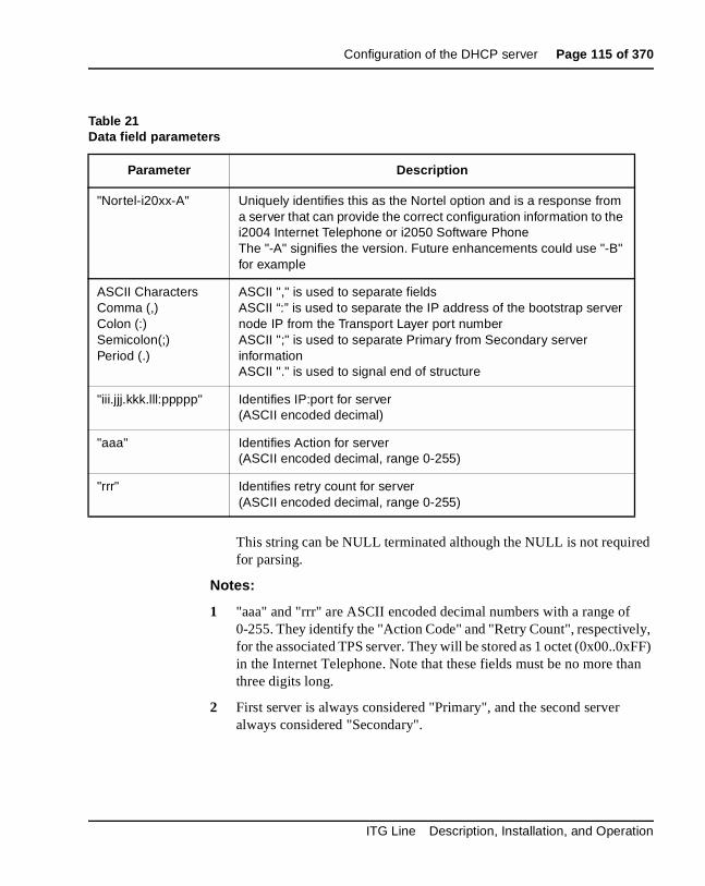
Configuration of the DHCP server Page 115 of 370
This string can be NULL terminated although the NULL is not required for parsing.
Notes:
1 "aaa" and "rrr" are ASCII encoded decimal numbers with a range of 0-255. They identify the "Action Code" and "Retry Count", respectively, for the associated TPS server. They will be stored as 1 octet (0x00..0xFF) in the Internet Telephone. Note that these fields must be no more than three digits long.
2 First server is always considered "Primary", and the second server always considered "Secondary".
Table 21Data field parameters
Parameter Description
"Nortel-i20xx-A" Uniquely identifies this as the Nortel option and is a response from a server that can provide the correct configuration information to the i2004 Internet Telephone or i2050 Software PhoneThe "-A" signifies the version. Future enhancements could use "-B" for example
ASCII CharactersComma (,)Colon (:)Semicolon(;)Period (.)
ASCII "," is used to separate fieldsASCII “:” is used to separate the IP address of the bootstrap server node IP from the Transport Layer port numberASCII ";" is used to separate Primary from Secondary server informationASCII "." is used to signal end of structure
"iii.jjj.kkk.lll:ppppp" Identifies IP:port for server (ASCII encoded decimal)
"aaa" Identifies Action for server (ASCII encoded decimal, range 0-255)
"rrr" Identifies retry count for server (ASCII encoded decimal, range 0-255)
ITG Line Description, Installation, and Operation

Page 116 of 370 Configuration of the DHCP server
3 If only one server is required, terminate primary TPS sequence immediately with "." instead of ";" for example "Nortel-i20xx-A,iii.jjj.kkk.lll:ppppp,aaa,rrr."
4 Valid options are one or two servers (0 or 3 is not allowed). However, it is recommended that the two server option is used. For i2004 Internet Telephone firmware version 3002B00, the valid option is two servers.
Note: If there is only one connect server (that is, only one ITG Line node is configured), enter the same information for server 1 and server 2.
5 Action code values:
0 – reserved
1 – UNIStim Hello (currently only this type is a valid choice)
2-254 – reserved
255 – reserved
6 iii,jjj,kkk,lll are ASCII encoded, decimal numbers representing the IP address of the server. They do not need to be three digits long as the . and : delimiters guarantee parsing. For example, '001', '01', and '1' would all be parsed correctly and interpreted as value 0x01 internal to the Internet Telephone.These fields must be no more than three digits long each.
7 ppppp is the port number in ASCII encoded decimal. It does not need to be five digits long as the : and , delimiters guarantee parsing. For example, '05001', '5001', '1', '00001' would all be parsed correctly and accepted as correct. The valid range is 0-65535 which is stored internally in Internet Telephone as hexadecimal in range 0..0xFFFF. This field must be no more than five digits long.
8 In all cases, the ASCII encoded numbers are treated as decimal values and all leading zeros are ignored. More specifically, a leading zero does not change the interpretation of the value to be OCTAL encoded. For example, 0021, 021, and 21 are all parsed and interpreted as decimal 21.
—————————— End of Notes——————————
553-3001-204 Standard 3.00 March 2002
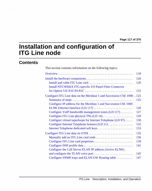
Page 117 of 370
180
Installation and configuration ofITG Line nodeContents
This section contains information on the following topics:
Overview . . . . . . . . . . . . . . . . . . . . . . . . . . . . . . . . . . . . . . . . . . . . . . . . 118
Install the hardware components . . . . . . . . . . . . . . . . . . . . . . . . . . . . . . 120Install and cable ITG Line card . . . . . . . . . . . . . . . . . . . . . . . . . . . . 120Install NTCW84JA ITG-specific I/O Panel Filter Connector for Option 51C/61C/81/81C . . . . . . . . . . . . . . . . . . . . . . . . . . . . . . . 122
Configure ITG Line data on the Meridian 1 and Succession CSE 1000 . .125Summary of steps . . . . . . . . . . . . . . . . . . . . . . . . . . . . . . . . . . . . . . . 125Configure IP address for the Meridian 1 and Succession CSE 1000 ELNK Ethernet Interface (LD 117) . . . . . . . . . . . . . . . . . . . . . . . . . 126Configure VoIP bandwidth management zones (LD 117) . . . . . . . . 127Configure ITG Line physical TNs (LD 14) . . . . . . . . . . . . . . . . . . . 129Configure virtual superloops for Internet Telephone (LD 97) . . . . . 130Configure Internet Telephone features (LD 11) . . . . . . . . . . . . . . . . 132Internet Telephone dedicated soft keys . . . . . . . . . . . . . . . . . . . . . . 133
Configure ITG Line data on OTM . . . . . . . . . . . . . . . . . . . . . . . . . . . . 135Manually add an ITG Line card node . .. . . . . . . . . . . . . . . . . . . . . . 136Configure ITG Line card properties . . . . . . . . . . . . . . . . . . . . . . . . . 139Configure DSP profile data . . . . . . . . . . . . . . . . . . . . . . . . . . . . . . . 141Configure the Call Server ELAN IP address (Active ELNK) and configure the TLAN voice port . . . . . . . . . . . . . . . . . . . . . . . . . 145Configure SNMP traps and ELAN GW Routing table . . . . . . . . . . 147
ITG Line Description, Installation, and Operation

Page 118 of 370 Installation and configuration of ITG Line node
Transmit ITG Line node configuration data from OTM to the ITG Line cards . . . . . . . . . . . . . . . . . . . . . . . . . . . . . . . . . . . . . . . . . . . 149
Overview . . . . . . . . . . . . . . . . . . . . . . . . . . . . . . . . . . . . . . . . . . . . . 150Set the Leader 0 IP address . . . . . . . . . . . . . . . . . . . . . . . . . . . . . . . 150Transmit node and card properties to Leader 0 . . . . . . . . . . . . . . . . 152Transmit card properties to all cards in the node . . . . . . . . . . . . . . . 154
Upgrade the ITG Line card software and i2004 Internet Telephone firmware . . . . . . . . . . . . . . . . . . . . . . . . . . . . . . . . . . . . . . . . . . . . . . . . 155
i2004 Internet Telephone firmware requirements . . . . . . . . . . . . . . 156Firmware upgrade from a new ITG Line card . . . . . . . . . . . . . . . . . 156Verify card software and i2004 Internet Telephone firmware . .. . . 156Upgrade ITG Line card software from the web . . . . . . . . . . . . . . . . 159Upgrade i2004 Internet Telephone firmware . . . . . . . . . . . . . . . . . . 161
Configure OTM alarm notification to receive ITG Line SNMP traps . . . . . . . . . . . . . . . . . . . . . . . . . . . . . . . . . . . . . . . . . . . . . . 167
Configure security for SNMP access . . . . . . . . . . . . . . . . . . . . . . . . . . 173
Changing the ITGL> CLI shell user name and password . . . . . . . . . . 174
Configure the Internet Telephone Installer Passwords . . . . . . . . . . . . . 176Internet Telephone Installer Password . . . . . . . . . . . . . . . . . . . . . . . 176
OverviewThis chapter explains how to install and configure new Internet Telephony Gateway (ITG) Line nodes, cards and associated cables; configure ITG Line data on Optivity Telephone Manager (OTM) and transmit to ITG Line cards; upgrade ITG Line card software; and upgrade i2004 Internet Telephone firmware.
The following is a list of procedures contained in this chapter:
• “ITG Line card installation” on page 120
• “Replace existing I/O Panel Filter Connector” on page 122
• “Installing the NTMF94EA ELAN, TLAN, serial interface cable” on page 124
• “Configure the ELAN IP address for the Meridian 1 and Succession CSE 1000 active ELNK Ethernet interface” on page 126
553-3001-204 Standard 3.00 March 2002
Installation and configuration of ITG Line node Page 119 of 370
• “Add an ITG Line card node manually” on page 136
• “Configure ITG Line card properties” on page 140
• “Configuring DSP profile data” on page 142
• “Configure the Call Server ELAN IP address (Active ELNK) and configure the TLAN voice port” on page 145
• “Configuring SNMP traps and ELAN GW Routing table” on page 147
• “Set the Leader 0 IP address” on page 150
• “Transmit node and card properties to Leader 0” on page 152
• “Transmit card properties to all cards in the node” on page 154
• “Verify card software and i2004 Internet Telephone firmware” on page 157
• “Upgrade ITG Line card software from the web” on page 160
• “Upgrade i2004 Internet Telephone firmware” on page 162
• “Configure SNMP Traps” on page 167
• “Configuring security for OTM SNMP access” on page 173
• “Changing the ITGL> CLI shell user name and password” on page 175
• “Configure the administrative Internet Telephone Installer Password” on page 177
• “Configure the temporary Internet Telephone Installer Password” on page 179
Read the “IP Network Engineering Guidelines” on page 51 before installing an ITG Line node.
ITG Line Description, Installation, and Operation

Page 120 of 370 Installation and configuration of ITG Line node
Install the hardware componentsInstall and cable ITG Line card
Each ITG Line card requires two slots in the Meridian 1 and Succession CSE 1000 IPE shelf. Only the left slot of the card connects to the Meridian 1 and Succession CSE 1000 IPE Backplane and I/O panel.
You can install a maximum of eight ITG Line cards in an IPE shelf in Option 51C/61C/81/81C. The ITG Line card can occupy any two adjacent slots in an IPE shelf, with the left slot of the card plugging into slots 0 to 6 and 8 to 15. You cannot plug in the left slot of an ITG Line card in slot 7, because the XPEC card is situated in-between slots 7 and 8.
To allow a module to hold the maximum number of ITG Line cards, install each card with the left slot of the card inserted into an even-numbered slot.
To install an ITG Line card, follow the steps in Procedure 5.
Procedure 5ITG Line card installation
1 For each ITG Line card in the node, identify the IPE card slot selected for the ITG Line card. Use the information from the “ITG Line card installation summary sheet” on page 101, and Table 22 on page 121.
Note: Even though the ITG Line card is a two-slot card, only the left slot is counted for the card slot number. Example: the slot number is 2 for an ITG Line card installed in slots 2 and 3.
2 Remove any existing I/O panel cabling associated with any card previously installed in the selected card slot.
3 Pull the top and bottom locking devices away from the ITG Line Leader 0 card faceplate.
CAUTIONWear an electrostatic discharge strap when handling ITG Line cards. As an additional safety measure handle all cards by the edges, and when possible, with the loosened packaging material still around the component.
553-3001-204 Standard 3.00 March 2002

Installation and configuration of ITG Line node Page 121 of 370
4 Insert the ITG Line card into the card guides and gently push it until it makes contact with the backplane connector. Hook the locking devices.
Note 1: The red LED on the faceplate remains lit until the card is configured and enabled in software, at which point it turns off.
Note 2: The faceplate display window displays startup self-test results (T:xx) and status messages. A display “F:xx” indicates a failure of the self-test. It is normal for the card to display “F:10” during the start-up self-test. F:10 indicates that the self-test did not find a Security Device. The ITG Line card does not have a security device. Some failures indicate that the card must be replaced.
Refer to “Faceplate maintenance display code” on page 245 for a listing of display codes.
—————————— End of Procedure ——————————
Table 22ITG Line installation by module type
Meridian 1 Modules ITG Line Card Slots
NT8D37BA/EC IPE modules, NT8D11BC/ED CE/PE modules
All available IPE card slots.
NT8D37AA/DC IPE modules 0, 4, 8, and 12
NT8D11AC/DC CE/PE modules 0
ITG Line Description, Installation, and Operation
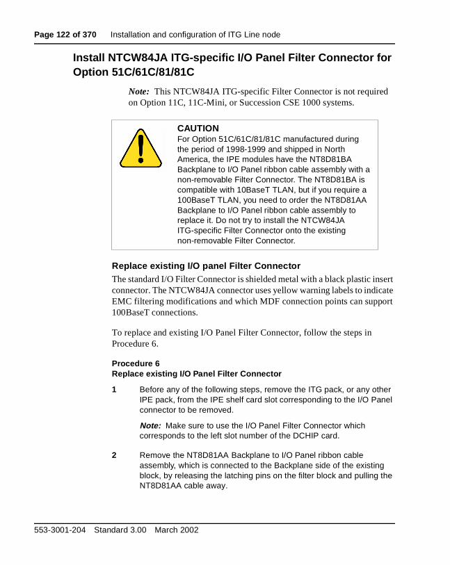
Page 122 of 370 Installation and configuration of ITG Line node
Install NTCW84JA ITG-specific I/O Panel Filter Connector for Option 51C/61C/81/81C
Note: This NTCW84JA ITG-specific Filter Connector is not required on Option 11C, 11C-Mini, or Succession CSE 1000 systems.
Replace existing I/O panel Filter ConnectorThe standard I/O Filter Connector is shielded metal with a black plastic insert connector. The NTCW84JA connector uses yellow warning labels to indicate EMC filtering modifications and which MDF connection points can support 100BaseT connections.
To replace and existing I/O Panel Filter Connector, follow the steps in Procedure 6.
Procedure 6Replace existing I/O Panel Filter Connector
1 Before any of the following steps, remove the ITG pack, or any other IPE pack, from the IPE shelf card slot corresponding to the I/O Panel connector to be removed.
Note: Make sure to use the I/O Panel Filter Connector which corresponds to the left slot number of the DCHIP card.
2 Remove the NT8D81AA Backplane to I/O Panel ribbon cable assembly, which is connected to the Backplane side of the existing block, by releasing the latching pins on the filter block and pulling the NT8D81AA cable away.
CAUTIONFor Option 51C/61C/81/81C manufactured during the period of 1998-1999 and shipped in North America, the IPE modules have the NT8D81BA Backplane to I/O Panel ribbon cable assembly with a non-removable Filter Connector. The NT8D81BA is compatible with 10BaseT TLAN, but if you require a 100BaseT TLAN, you need to order the NT8D81AA Backplane to I/O Panel ribbon cable assembly to replace it. Do not try to install the NTCW84JA ITG-specific Filter Connector onto the existing non-removable Filter Connector.
553-3001-204 Standard 3.00 March 2002

Installation and configuration of ITG Line node Page 123 of 370
3 Unscrew the existing Filter Connector from the I/O panel. There is one screw on the lower front of the connector and one screw on the upper back of the connector. Remove the connector.
4 Re-position the new NTCW84JA Filter Connector in the now vacant I/O panel opening (see Figure 11 on page 123).
5 Attach the new NTCW84JA ITG-specific Filter Connector to the I/O panel by securely fastening the top back screw and the bottom front screw.
6 Reconnect the NT8D81AA cable and secure it in place by snapping shut the locking latches provided on the NTCW84JA connector.
—————————— End of Procedure ——————————
Figure 11NTCW84JA 50 pin ITG-specific I/O Panel Filter Connector for Option 51C/61C/81/81C
System BackplaneSide (Inside I/O Panel)
NT8D81AA Cable
MDF Cable
Exterior side of
System I/O Panel
System (to MDF, etc.)
ITG Line Description, Installation, and Operation
Page 124 of 370 Installation and configuration of ITG Line node
Install the NTMF94EA ELAN, TLAN, serial interface cableThe NTMF94EA cable provides the ELAN, TLAN and serial interface for the NT8R17 IP Line card. Refer to “NTMF94EA I/O cable” on page 285 for pinouts and technical specifications on the NTMF94EA cable. To install the NTMF94EA ELAN, TLAN, serial interface cable, complete the steps in Procedure 7.
Procedure 7Installing the NTMF94EA ELAN, TLAN, serial interface cable
1 On Option 51C/61C/81/81C, connect the NTMF94EA ELAN, TLAN, and RS232 Serial Maintenance I/O cable to the I/O panel connector for the left hand card slot.
If you have an Option 11C or 11C-Mini, connect the cable to the I/O connector in the cabinet that corresponds to the IP Line card slot (see Figure 48 on page 287).
2 Connect a shielded Category 5 cable from the customer’s TLAN hub or switch equipment to the port labeled "T-LAN".
3 Connect a shielded Category 5 cable from the customer’s ELAN hub or switch equipment to the port labeled "E-LAN".
WARNINGPlug all ITG Line card ELAN interfaces belonging to the same node into the same ELAN hub or Layer 2 switch port group.
553-3001-204 Standard 3.00 March 2002

Installation and configuration of ITG Line node Page 125 of 370
4 Install the NTAG81CA serial cable into the faceplate Maintenance port. You will use this connection in Procedure 14 to configure the IP address for Leader 0. If required, use the NTAG81BA maintenance extender cable
Note: Alternatively, for a permanent connection to the maintenance port, use the DB9 female connector on the NTMF94BA breakout cable to connect a modem (using a null modem) or directly to a local TTY terminal.
Note 1: The hub LEDs and the faceplate link LEDs light when you connect the card to the WAN/LAN through the TLAN port.
Note 2: Refer to “IP Network Engineering Guidelines” on page 51 for more details about engineering and connecting the LAN/WAN.
—————————— End of Procedure ——————————
Configure ITG Line data on the Meridian 1 and Succession CSE 1000
Summary of steps
1 Configure IP address for the Meridian 1 and Succession CSE 1000 ELNK Ethernet Interface (LD 117) (see page 126).
2 Configure VoIP bandwidth management zones (LD 117) (see page 127).
3 Configure ITG Line physical TNs (LD 14) (see page 129).
4 Configure virtual superloops for Internet Telephone (LD 97) (page 130).
5 Configure Internet Telephone features (LD 11) (see page 132).
WARNINGThe serial maintenance ports presented at the faceplate and at the backplane are identical. Do not connect a terminal to both access points simultaneously. This will result in incorrect and unpredictable operation of the ITG Line card.
ITG Line Description, Installation, and Operation

Page 126 of 370 Installation and configuration of ITG Line node
Before you proceed:
• Verify the Meridian 1 and Succession CSE 1000 software release running on your system. The minimum required software release to support ITG Line is R25.40.
• Verify the ISM System Limit in Overlay 22. The ISM system limit must have sufficient unused units to support the number of Internet Telephones you are installing. Refer to the Meridian 1 and Succession CSE 1000 System Maintenance Guide (NTP 553-3001-511).
• Expand the ISM System Limit, if required, by ordering additional ISM Parameters. Refer to Table 3, “Meridian 1 and Succession CSE 1000 ITG Line package components,” on page 18, “Ordering rules for ITG Line” on page 19, and “ISM parameters” on page 42.
Note: In the following procedures, the term Intrazone means within the same zone, and Interzone means between two different zones.
Configure IP address for the Meridian 1 and Succession CSE 1000 ELNK Ethernet Interface (LD 117)
To configure the ELAN IP address for the Meridian 1 and Succession CSE 1000 active ELNK Ethernet interface, follow the steps in Procedure 8.
Procedure 8Configure the ELAN IP address for the Meridian 1 and Succession CSE 1000 active ELNK Ethernet interface
1 Go to Overlay 117.
2 Create host entries with IP address on the ELAN subnet by entering one of the following commands:
NEW HOST PRIMARY_IP xx.xx.xx.xx
NEW HOST SECONDARY_IP xx.xx.xx.xx (for Option 61C and Option 81/81C only)
3 Assign host entry IP address to active and inactive ELNK interfaces on ELAN by entering one of the following commands:
CHG ELNK ACTIVE PRIMARY_IP
CHG ELNK INACTIVE SECONDARY_IP (for Dual CPU only)
553-3001-204 Standard 3.00 March 2002
Installation and configuration of ITG Line node Page 127 of 370
4 Verify your IP address for the Ethernet by entering the following command: PRT ELNK.
5 Enter the following: Update DBS.
6 Go to Overlay 137. Check the status of the Ethernet interface by entering the command: STAT ENLK. If the ELNK is disabled, enable it by entering: ENL ELNK.
—————————— End of Procedure ——————————
Configure VoIP bandwidth management zones (LD 117)In Overlay 117 you can define up to 256 zones. The Audio Connection Proxy uses the zones for VoIP bandwidth management. For more information, see “VoIP bandwidth management zones” on page 64.
Table 23 on page 128, lists the four zone parameters as:
• p1 - Total bandwidth (Kbps) available for Intrazone calls
• p2 - Defines the codec for Intrazone calls (that is, preserve voice quality or preserve bandwidth). BQ provides Best Quality but uses the most bandwidth, whereas BB uses the least amount of Bandwidth but reduces voice quality
• p3 - The total bandwidth available for Interzone calls
• p4 - The preferred strategy for the choice of the codec for Interzone calls
Overlay 117 also includes DIS and ENL commands to disable or enable a zone. When you create a zone, its default state is enabled.
CAUTIONZone 0 must be configured in Overlay 117 before other zones are configured or all calls associated with zone 0 will be blocked.
ITG Line Description, Installation, and Operation

Page 128 of 370 Installation and configuration of ITG Line node
Table 23LD 117 bandwidth management zones configuration
Command Description
NEW ZONE xxx p1 p2 p3 p4 User creates a new zone, where:xxx = zone number = (0) - 255.p1 = Intrazone available bandwidth = 0 - (10000) - 100000 (Kbps)p2 = Intrazone preferred strategy = BQ for Best Quality or BB for Best Bandwidthp3 = Interzone available bandwidth= 0 - (10000) - 100000 (Kbps)p4 = Interzone preferred strategy = BQ for Best Quality or BB for Best Bandwidth
New ZONE xxx User creates a new zone with default values for the parameters:p1 = 10000 (Kbps)p2 = BQp3 = 10000 (Kbps)p4 = BQ
CHG ZONE xxx p1 p2 p3 p4 User changes parameters of a zone. All parameters must be re-entered, even those that are unchanged.
OUT ZONE xxx User removes a zone.
DIS ZONE xxx Allows user to disable a zone. When you disable zone, no new calls are established inside, from or toward this zone.
ENL ZONE xxx Allows user to enable a zone.
PRT ZONE xxx Prints zone and bandwidth information.
553-3001-204 Standard 3.00 March 2002
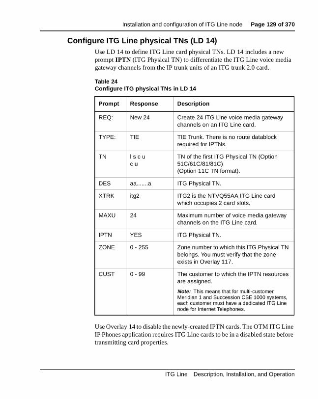
Installation and configuration of ITG Line node Page 129 of 370
Configure ITG Line physical TNs (LD 14)Use LD 14 to define ITG Line card physical TNs. LD 14 includes a new prompt IPTN (ITG Physical TN) to differentiate the ITG Line voice media gateway channels from the IP trunk units of an ITG trunk 2.0 card.
Use Overlay 14 to disable the newly-created IPTN cards. The OTM ITG Line IP Phones application requires ITG Line cards to be in a disabled state before transmitting card properties.
Table 24Configure ITG physical TNs in LD 14
Prompt Response Description
REQ: New 24 Create 24 ITG Line voice media gateway channels on an ITG Line card.
TYPE: TIE TIE Trunk. There is no route datablock required for IPTNs.
TN l s c uc u
TN of the first ITG Physical TN (Option 51C/61C/81/81C)(Option 11C TN format).
DES aa.......a ITG Physical TN.
XTRK itg2 ITG2 is the NTVQ55AA ITG Line card which occupies 2 card slots.
MAXU 24 Maximum number of voice media gateway channels on the ITG Line card.
IPTN YES ITG Physical TN.
ZONE 0 - 255 Zone number to which this ITG Physical TN belongs. You must verify that the zone exists in Overlay 117.
CUST 0 - 99 The customer to which the IPTN resources are assigned.
Note: This means that for multi-customer Meridian 1 and Succession CSE 1000 systems, each customer must have a dedicated ITG Line node for Internet Telephones.
ITG Line Description, Installation, and Operation

Page 130 of 370 Installation and configuration of ITG Line node
Configure virtual superloops for Internet Telephone (LD 97)You must configure one or more virtual superloops to support Internet Telephone Virtual TNs (VTNs).
Option 51C/61C/81/81CIn Option 51C/61C/81/81C, virtual superloops contend for the same range of loops with phantom, standard and remote superloops, digital trunk loops and all service loops. Virtual superloops can reside in physically equipped network groups, or in virtual network groups.
Without FIBN, Package 365, there is a maximum of five network groups available, 0 - 4. With Package 365, there are a maximum of eight network groups, 0 - 7. For normal traffic engineering, provision up to 1024 VTNs on a single virtual superloop for an Option 51C/61C/81/81C. For non-blocking, do not exceed 120 VTNs on a single virtual superloop, for an Option 51C/61C/81/81C.
It is recommended that you start configuring Virtual Superloops in the highest non-physically equipped group available. Table 24 lists the prompts and responses required to configure virtual superloops in Overlay 97.
Table 25Virtual Superloop configuration in LD 97
Prompt Response Description
REQ: CHG Change.
TYPE: SUPL Superloop.
SUPL Vxxx V stands for a virtual superloop and xxx is the number of the virtual superloop.xxx = 0-156 and multiple of four for Option 51C/61C/81/81C without FIBN package 365.xxx = 0-252 and multiple of four for Option 51C/61C/81/81C with FIBN package 365.xxx = 96-112 and multiple of four for Option 11C and 11C-Mini.
553-3001-204 Standard 3.00 March 2002

Installation and configuration of ITG Line node Page 131 of 370
Option 11C/11C-MiniIn Option 11C/11C-Mini, virtual superloops contend for the same range of superloops, 96-112, with phantom superloops.
Up to 128 VTNs can be configured on a single virtual superloop for an Option 11C/11C-Mini, for a maximum number of 640 VTNs in each system.
In Option 11C/11C-Mini, mapping virtual superloops to virtual cards is the same as mapping phantom superloops to phantom cards (see Table 26 on page 131).
Table 26Virtual superloop/virtual card mapping for Option 11C/11C-Mini
SUPL Card
96 61-64
100 65-68
104 69-72
108 73-76
112 77-80
ITG Line Description, Installation, and Operation

Page 132 of 370 Installation and configuration of ITG Line node
Configure Internet Telephone features (LD 11)The existing ISM header that is printed at the start of Overlay 11 includes the new ISM limit for the Internet Telephone. Refer to Table 27 to configure the i2004 Internet Telephone or the i2050 Software Phone in Overlay 11.
Table 27LD 11 Configure an Internet Telephone
Prompt Response Description
REQ:NEWCHGPRTOUTCPYMOV
Action request. NewChangePrintOutCopyMove
TYPE: I2004I2050
For model i2004 Internet Telephone or i2050 Software Phone. Meridian 1 and Succession CSE 1000 accepts this response if it is equipped with packages 88 and 170.
TN l s c u
c u
Enter loop (virtual loop), shelf, card, and unit (terminal number), where unit = 0 - 31 Slot (virtual slot) and unit for Option 11C.
Note: See Table 26 on page 131 for virtual superloop to virtual card slot mapping for Option 11C/11C-Mini.
des a...z ODAS telephone designator.
CUST 0-99 Customer number.
553-3001-204 Standard 3.00 March 2002
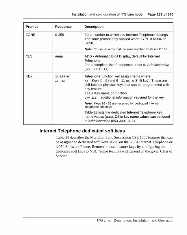
Installation and configuration of ITG Line node Page 133 of 370
Internet Telephone dedicated soft keysTable 28 describes the Meridian 1 and Succession CSE 1000 features that can be assigned to dedicated soft Keys 16-26 on the i2004 Internet Telephone or i2050 Software Phone. Remove unused feature keys by configuring the dedicated soft keys to NUL. Some features will depend on the given Class of Service.
ZONE 0-255 Zone number to which this Internet Telephone belongs. The zone prompt only applied when TYPE = i2004 or i2050.
Note: You must verify that the zone number exists in LD 117.
CLS aaaa ADD - Automatic Digit Display, default for Internet Telephone.For a complete list of responses, refer to Administration (553-3001-311).
KEY xx aaa yy zz...zz
Telephone function key assignments where:xx = Keys 0 - 5 (and 6 - 11 using Shift key). These are self-labeled physical keys that can be programmed with any feature. aaa = Key name or functionyyy, zzz = additional information required for the key.
Note: Keys 16 - 26 are reserved for dedicated Internet Telephone soft keys.
Table 28 lists the dedicated Internet Telephone key name values (aaa). Other key name values can be found in Administration (553-3001-311).
Prompt Response Description
ITG Line Description, Installation, and Operation
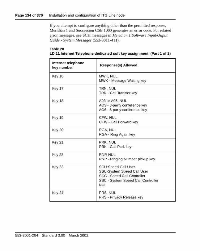
Page 134 of 370 Installation and configuration of ITG Line node
If you attempt to configure anything other than the permitted response, Meridian 1 and Succession CSE 1000 generates an error code. For related error messages, see SCH messages in Meridian 1 Software Input/Ouput Guide - System Messages (553-3011-411).
Table 28LD 11 Internet Telephone dedicated soft key assignment (Part 1 of 2)
Internet telephonekey number
Response(s) Allowed
Key 16 MWK, NULMWK - Message Waiting key
Key 17 TRN, NULTRN - Call Transfer key
Key 18 A03 or A06, NULAO3 - 3-party conference keyAO6 - 6-party conference key
Key 19 CFW, NULCFW - Call Forward key
Key 20 RGA, NULRGA - Ring Again key
Key 21 PRK, NULPRK - Call Park key
Key 22 RNP, NULRNP - Ringing Number pickup key
Key 23 SCU-Speed Call UserSSU-System Speed Call UserSCC - Speed Call ControllerSSC - System Speed Call ControllerNUL
Key 24 PRS, NULPRS - Privacy Release key
553-3001-204 Standard 3.00 March 2002
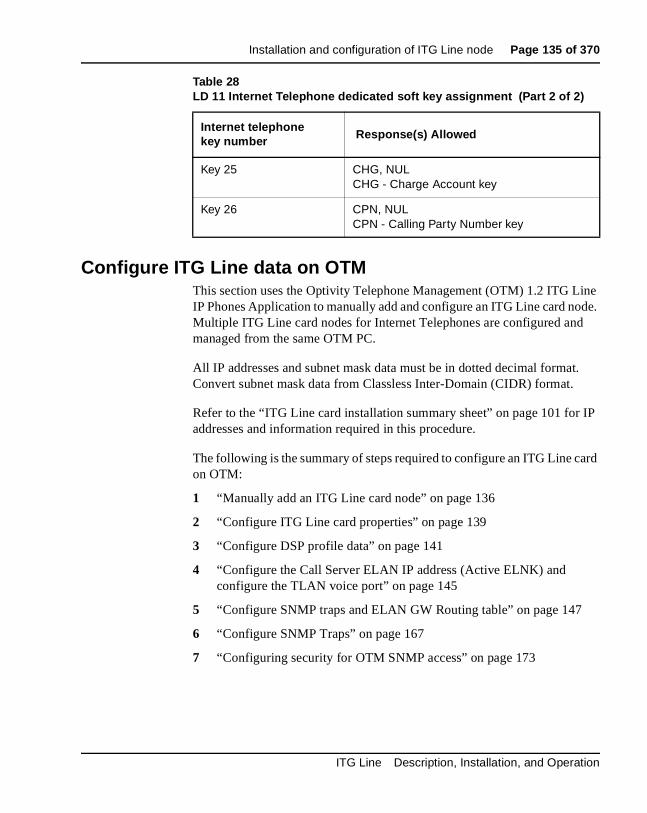
Installation and configuration of ITG Line node Page 135 of 370
Configure ITG Line data on OTMThis section uses the Optivity Telephone Management (OTM) 1.2 ITG Line IP Phones Application to manually add and configure an ITG Line card node. Multiple ITG Line card nodes for Internet Telephones are configured and managed from the same OTM PC.
All IP addresses and subnet mask data must be in dotted decimal format. Convert subnet mask data from Classless Inter-Domain (CIDR) format.
Refer to the “ITG Line card installation summary sheet” on page 101 for IP addresses and information required in this procedure.
The following is the summary of steps required to configure an ITG Line card on OTM:
1 “Manually add an ITG Line card node” on page 136
2 “Configure ITG Line card properties” on page 139
3 “Configure DSP profile data” on page 141
4 “Configure the Call Server ELAN IP address (Active ELNK) and configure the TLAN voice port” on page 145
5 “Configure SNMP traps and ELAN GW Routing table” on page 147
6 “Configure SNMP Traps” on page 167
7 “Configuring security for OTM SNMP access” on page 173
Key 25 CHG, NULCHG - Charge Account key
Key 26 CPN, NULCPN - Calling Party Number key
Table 28LD 11 Internet Telephone dedicated soft key assignment (Part 2 of 2)
Internet telephonekey number Response(s) Allowed
ITG Line Description, Installation, and Operation
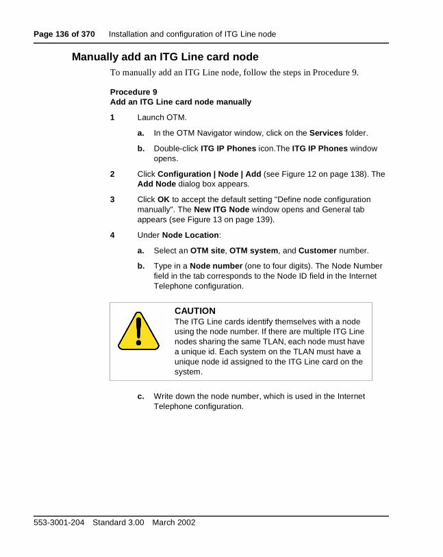
Page 136 of 370 Installation and configuration of ITG Line node
Manually add an ITG Line card nodeTo manually add an ITG Line node, follow the steps in Procedure 9.
Procedure 9Add an ITG Line card node manually
1 Launch OTM.
a. In the OTM Navigator window, click on the Services folder.
b. Double-click ITG IP Phones icon.The ITG IP Phones window opens.
2 Click Configuration | Node | Add (see Figure 12 on page 138). The Add Node dialog box appears.
3 Click OK to accept the default setting "Define node configuration manually". The New ITG Node window opens and General tab appears (see Figure 13 on page 139).
4 Under Node Location:
a. Select an OTM site, OTM system, and Customer number.
b. Type in a Node number (one to four digits). The Node Number field in the tab corresponds to the Node ID field in the Internet Telephone configuration.
c. Write down the node number, which is used in the Internet Telephone configuration.
CAUTIONThe ITG Line cards identify themselves with a node using the node number. If there are multiple ITG Line nodes sharing the same TLAN, each node must have a unique id. Each system on the TLAN must have a unique node id assigned to the ITG Line card on the system.
553-3001-204 Standard 3.00 March 2002
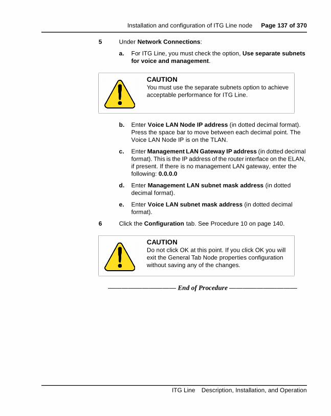
Installation and configuration of ITG Line node Page 137 of 370
5 Under Network Connections:
a. For ITG Line, you must check the option, Use separate subnets for voice and management.
b. Enter Voice LAN Node IP address (in dotted decimal format). Press the space bar to move between each decimal point. The Voice LAN Node IP is on the TLAN.
c. Enter Management LAN Gateway IP address (in dotted decimal format). This is the IP address of the router interface on the ELAN, if present. If there is no management LAN gateway, enter the following: 0.0.0.0
d. Enter Management LAN subnet mask address (in dotted decimal format).
e. Enter Voice LAN subnet mask address (in dotted decimal format).
6 Click the Configuration tab. See Procedure 10 on page 140.
—————————— End of Procedure ——————————
CAUTIONYou must use the separate subnets option to achieve acceptable performance for ITG Line.
CAUTIONDo not click OK at this point. If you click OK you will exit the General Tab Node properties configuration without saving any of the changes.
ITG Line Description, Installation, and Operation

Page 138 of 370 Installation and configuration of ITG Line node
Figure 12ITG Telephony Gateway main window
553-3001-204 Standard 3.00 March 2002

Installation and configuration of ITG Line node Page 139 of 370
Figure 13New ITG Node–General tab
Configure ITG Line card propertiesIf the IP Network administrator provides IP addresses and subnet masks in CIDR format, for example, "10.1.1.10/24", you must convert the subnet mask to dotted decimal format. See Appendix D: “Subnet mask conversion from CIDR to dotted decimal format” on page 323 for help.
Note 1: On the Configuration tab, you can Add, Change, or Delete the ITG Line cards in the node one at a time.
Note 2: You cannot delete the Leader 0 card in the Configuration tab. You must delete the node in order to delete Leader 0.
To configure the properties of the ITG Line card, follow the steps in Procedure 10 on page 140.
ITG Line Description, Installation, and Operation
Page 140 of 370 Installation and configuration of ITG Line node
Procedure 10Configure ITG Line card properties
1 Enter the Card Properties data for Leader 0 and Follower cards:
a. Card role: Assign the Card role as Leader 0 for the first card you configure. For the remaining cards, assign the Card role as Follower.
b. Management IP: This is the ELAN IP address for the card. OTM and Meridian 1 and Succession CSE 1000 use this address to communicate with the card.
c. Management MAC: This is the motherboard Ethernet address from your “ITG Line card installation summary sheet” on page 101.
d. Voice IP: This is the TLAN IP address for the card.
e. Voice LAN gateway IP: This is the IP address of the router interface on the TLAN.
f. Card TN: For Option 51C/61C/81/81C systems, enter Card TN (l s c) information. For Option 11C, 11C-Mini, and Succession CSE 1000 systems, enter only the card slot number between 1-50. The card TN format is determined by the Meridian 1 and Succession CSE 1000 system type which is configured in the OTM navigator. You must enter the correct system type in the OTM Navigator before you add the node.
g. Click Add. The card role and address information appears in a working list at the bottom of the New ITG Node window.
2 Click Apply to add the Card Properties to the Node.
Note: If you prematurely click OK at this point, you will exit from the window and the changes will be saved. Double-click the new node in the upper part of the main ITG IP Phones window to re-open Node Properties and complete the configuration procedures.
—————————— End of Procedure ——————————
553-3001-204 Standard 3.00 March 2002
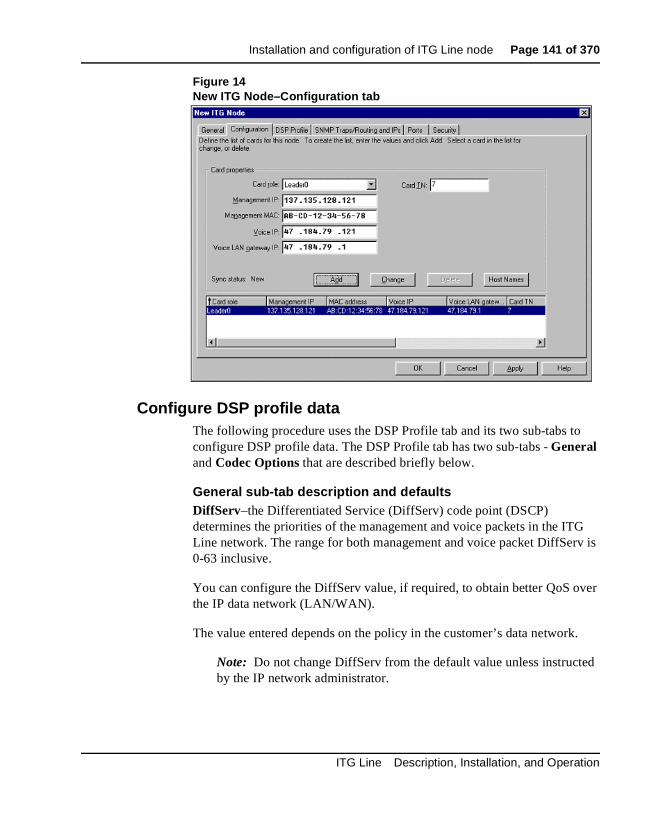
Installation and configuration of ITG Line node Page 141 of 370
Figure 14New ITG Node–Configuration tab
Configure DSP profile data The following procedure uses the DSP Profile tab and its two sub-tabs to configure DSP profile data. The DSP Profile tab has two sub-tabs - General and Codec Options that are described briefly below.
General sub-tab description and defaultsDiffServ–the Differentiated Service (DiffServ) code point (DSCP) determines the priorities of the management and voice packets in the ITG Line network. The range for both management and voice packet DiffServ is 0-63 inclusive.
You can configure the DiffServ value, if required, to obtain better QoS over the IP data network (LAN/WAN).
The value entered depends on the policy in the customer’s data network.
Note: Do not change DiffServ from the default value unless instructed by the IP network administrator.
ITG Line Description, Installation, and Operation

Page 142 of 370 Installation and configuration of ITG Line node
Loss and Level Plan–determines parameters, such as transmission gain, that vary from country to country. The Loss and Level Plan values are stored in a file on the OTM PC. OTM reads the file to acquire the loss and level values for the selected country and places the values in a config.ini file on the ITG Line cards.
Enable Echo Canceller checkbox–do not uncheck this box. Never disable echo canceller unless directed by Nortel Networks Field Support.
Echo canceller tail delay–use the maximum value available in the pull down menu. Never reduce the echo canceller value unless otherwise directed by Nortel Networks Field Support.
Voice activity detection–the range is -20 to +10 dB. The default is -17.
Jitter buffer–the range is 0-200 ms. The default is 50 ms or the next highest setting that the device allows. For more information, see “Adjusting jitter buffer size” on page 87.
Codec options sub-tab descriptionThe Codec options sub-tab presents a table of different sets of codec options identified by a codec setting index number. The lesser codec setting index corresponds to BQ (Best Quality) in Overlay 117 zone configuration. The greater codec setting index corresponds to BB (Best Bandwidth). For more information, see“Codec selection” on page 88.
To configure the DSP profile, follow the steps in Procedure 11.
Procedure 11Configuring DSP profile data
1 Click the DSP Profile tab. The DSP Profile General sub-tab appears (Figure 15 on page 144).
2 Under Diffserv Codepoint, modify the DSCP Control and Voice values only as directed by the IP network administrator. The recommended configuration values are:
a. Control: A value of 40 - Class Selectore 5 (CS5)
b. Voice: A value of 46 Control DSCP - Expedited Forwarding (EF)
3 Under Loss and Level Plan, select your Country from the pull-down box.
553-3001-204 Standard 3.00 March 2002

Installation and configuration of ITG Line node Page 143 of 370
4 Under Codec Options, leave the values at their default settings unless directed to change them to Nortel Networks Field Support.
a. Enable echo canceller: Leave checked.
b. Echo canceller tail: Select the maximum value.
c. Voice activity detection: The default value is -17. The range is -20 to +10 dB
d. Jitter buffer: The default is 50ms. The range is 0 ms to 200 ms and this is determined by the codec.
5 Click Apply.
6 Click the Codec Options sub-tab (Figure 16 on page 145).
Note: The Codec Options sub-tab contains a list of up to 32 codec settings for G.711, G.729A, and G.729AB for the ITG Line card (see Figure 16 on page 145).
7 Check only two Codec # settings from the list.
The default Codec # settings are 4 and 17.
The Codec # indicates a particular codec (G.711 or G.729A) with different options for Frame Size and VAD (On or Off).
The lessor of the two Codec #s that you check corresponds to BQ (best quality) and BB (best bandwidth) in Overlay 17.
For example, if you select Codec # 13 and Codec # 14:
• Codec # 13 will correspond with best quality
• Codec # 14 will correspond with best bandwidth
8 Click Apply.
—————————— End of Procedure ——————————
ITG Line Description, Installation, and Operation
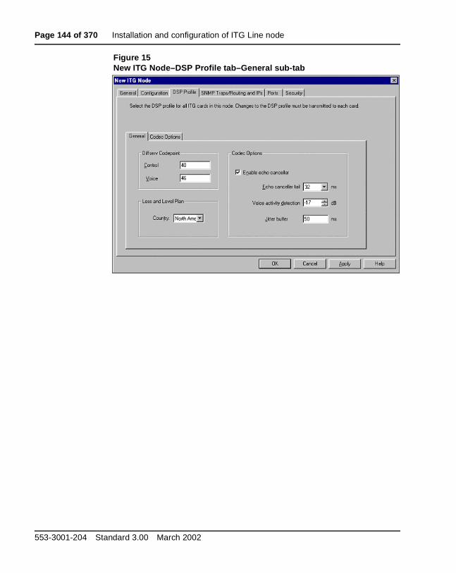
Page 144 of 370 Installation and configuration of ITG Line node
Figure 15New ITG Node–DSP Profile tab–General sub-tab
553-3001-204 Standard 3.00 March 2002

Installation and configuration of ITG Line node Page 145 of 370
Figure 16New ITG Node–DSP Profile tab–Codec Options sub-tab
Configure the Call Server ELAN IP address (Active ELNK) and configure the TLAN voice port
To configure the Call Server ELAN IP address (Active ELNK) and to also configure the TLAN voice port, follow the steps in Procedure 12.
Procedure 12Configure the Call Server ELAN IP address (Active ELNK) and configure the TLAN voice port
1 Click the Ports tab (see Figure 17 on page 147).
2 Enter the following ELAN settings:
a. Meridian 1 IP: Enter the Call Server ELAN IP Address (Active ELNK).
Note: The Call Server ELAN IP address must correspond to the Active ELNK IP address configured in Overlay 117. It must be in the same subnet as the ELAN for the ITG Line node.
ITG Line Description, Installation, and Operation

Page 146 of 370 Installation and configuration of ITG Line node
b. Survival Cabinet IP: If applicable, enter the Survivable Cabinet ELAN IP address (Active ELNK).
Note: The Survivable Cabinet IP address must correspond to the Active ELNK IP address for the Survivable Cabinet. This field will be disabled unless you have previously configured the Survivable Cabinet under the OTM Navigator Site and System. All ITC Line cards in the same node should be in the same Survivable Cabinet.
3 Change the TLAN Voice port only as instructed by the IP network administrator to improve quality of service for the Internet Telephones. For example, if RTP Header compression is used to reduce voice bandwidth on narrow band WAN links, then TLAN voice port range will need to be set to 16384 or higher. The exact range will be provided by your system administrator.
Note 1: The TLAN Voice port range is 1024 to 65535. The default Voice ports are 5200 - 5295. A check is performed to prevent the TLAN Voice and signaling UDP ports from having the same range.
Note 2: The TLAN Signaling occurs on UDP ports 7300, 4100, 5100, and 5000
—————————— End of Procedure ——————————
CAUTIONDo not use the Restore Defaults button on the Ports tab. It will change the Meridian 1 ELAN and Survival Cabinet IP addresses to invalid addresses.
553-3001-204 Standard 3.00 March 2002

Installation and configuration of ITG Line node Page 147 of 370
Figure 17New ITG Node–Ports tab
Configure SNMP traps and ELAN GW Routing tableProcedure 13Configuring SNMP traps and ELAN GW Routing table
1 Click the SNMP Traps/Routing and IPs tab in the Node Properties window (see Figure 18 on page 149).
2 Check the Enable SNMP traps checkbox, if you are configuring one or more SNMP management IP addresses to receive SNMP traps from cards in the ITG Line node.
ITG Line Description, Installation, and Operation

Page 148 of 370 Installation and configuration of ITG Line node
3 To add an SNMP Manager IP address, type the IP address in the SNMP traps entry fields, and click Add. Add SNMP Manager IP addresses for:
• the local OTM PC
• PPP IP address configured in the Netgear RM356 Modem Router, or equivalent, on the ELAN for the remote support OTM PC
• the SNMP manager for remote alarm monitoring
• any remote OTM PCs on the customer’s IP network
Note: A net route or host route through the management gateway is added to the ITG Line cards IP Routing Table for each SNMP management address that is added to the SNMP traps list.
4 To add a net route or host route through the ELAN router management gateway for a management host which does not receive SNMP traps, type the IP address and subnet mask in the entry field of the card routing table, and click Add.
5 Click OK to save and exit.
—————————— End of Procedure ——————————
553-3001-204 Standard 3.00 March 2002

Installation and configuration of ITG Line node Page 149 of 370
Figure 18New ITG Node–SNMP Traps/Routing and IPs tab
Transmit ITG Line node configuration data from OTM to the ITG Line cards
Before you begin, ensure the:
• NTVQ55AA ITG Line cards and cables have been installed.
• ELAN and TLAN interfaces of all ITG Line cards are connected with access to the IP network.
• ITG Line data has been configured on OTM.
• OTM PC is connected to the local ELAN subnet or to a remote subnet with IP router access to the ELAN and TLAN.
ITG Line Description, Installation, and Operation

Page 150 of 370 Installation and configuration of ITG Line node
OverviewITG Line node and card properties are configured in the OTM ITG Line IP Phones application and then transmitted to the ITG Line cards. The configuration data is converted to text files by OTM and transmitted to the line cards. The process consists of the following steps:
1 Set the Leader 0 IP address from TTY connected to local RS232 maintenance port.
2 Reboot Leader 0.
3 Transmit the node and card properties from OTM ITG Line IP Phones application to Leader 0.
4 Reboot Leader 0.
5 Transmit card properties to all cards in the node.
Set the Leader 0 IP addressFollow the step in Procedure 14 to set the IP address of the Leader 0 ITG Line card.
Procedure 14Set the Leader 0 IP address
1 Access the ITGL> CLI by connecting the COM port of a OTM PC to the RS232 serial maintenance port on the faceplate of the ITG Line Leader 0 card with an NTAG81CA PC Maintenance cable. If required, use an NTAG81BA Maintenance Extender cable between the PC Maintenance cable and the OTM PC.
Alternatively, connect the NTAG81BA Maintenance Extender cable to the female DB-9 connector of the NTMF94EA ELAN, TLAN RS232 Ports cable for a more permanent connection to the ITG Line card serial maintenance port.
Note: Never connect two terminals to the faceplate and I/O panel breakout cable serial maintenance port connectors at the same time.
2 Use the following communication parameters for the TTY terminal emulation on the OTM PC: 9600 baud, 8 bits, no parity, one stop bit.
3 Login to the ITGL> CLI and enter the setLeader command to set the Leader 0 Management LAN IP address, Management LAN gateway IP address and the Management LAN subnet mask.
553-3001-204 Standard 3.00 March 2002

Installation and configuration of ITG Line node Page 151 of 370
4 Observe the Leader 0 card faceplate maintenance display window.
When the display reads "T:20", it begins to send BootP requests on the ELAN. A series of dots is printed on the TTY.
5 Type +++ to escape from the BootP request.
6 At the Login prompt, enter the default user ID and password of itgadmin and itgadmin to access the ITGL> CLI:
itg Login: itgadmin
Password: itgadmin
7 When the maintenance window displays "T:21", at the ITGL> prompt, enter: setLeader “xx.xx.xx.xx”,“yy.yy.yy.yy”,“zz.zz.zz.zz”
Note 1: The three parameters must each be enclosed in double quotes. You must put a space after the command and before the first parameter. Put commas and no spaces between the following parameters:
“xx.xx.xx.xx”=IP address. Enter the same IP address you entered in the Management LAN IP field for Leader 0 in the ITG IP Phones Node Properties Configuration tab.
"yy.yy.yy.yy"=Gateway IP address. Enter the same address you entered in the Management LAN gateway IP field in the ITG IP Phones General tab. If there is none, enter the following: "0.0.0.0"
"zz.zz.zz.zz"=Management LAN subnet mask. Enter the same address you entered in the Management LAN subnet mask field in the General tab of the ITG IP Phones window.
Note 2: This step assumes you have already configured the new ITG Line node in OTM.
8 Reboot Leader 0 ITG Line card. At the ITGL prompt, enter: cardReset, or press the reset button on the faceplate of the Leader 0 ITG Line card.
9 Check the maintenance display for T:22 to confirm a successful reboot.
ITG Line Description, Installation, and Operation

Page 152 of 370 Installation and configuration of ITG Line node
10 From the OTM ITG Line IP Phones application, select Refresh view to show the card status. Otherwise, verify LAN connections and IP configuration.
—————————— End of Procedure ——————————
Transmit node and card properties to Leader 0To transmit the node and card properties to Leader 0, follow the steps in Procedure 15.
Procedure 15Transmit node and card properties to Leader 0
1 Login to Overlay 32 in Meridian 1. Disable the card in order to transmit the card properties.
2 Open OTM. From the OTM Navigator window, click on the Services folder to expand the menu. Double-click on ITG IP Phones. The IP Telephony Gateway - IP Phones window opens.
3 Select the ITG Line node to which you want to transmit configuration data from the list of ITG Line nodes in the upper part of the window.
4 Select the Configuration | Synchronize | Transmit. The “ITG - Transmit Options” window appears (see Figure 19 on page 153).
5 Leave the radio button default setting of Transmit to selected nodes. Check both the Node Properties to Active Leader and Card properties to all disabled cards check boxes.
6 Click the Start transmit button. Monitor progress in the “Transmit control” window. Confirm that the node and card properties are transmitted successfully to Leader 0.
Note: It is normal at this point, that the card properties fail to transmit to the other cards in the node, because they have not yet received the IP address from Leader 0 BootP server.
7 When the transmission is complete, click Close.
8 Reboot the Leader 0 ITG Line card. At the ITGL prompt, enter: cardReset or push the reset button on the ITG line card faceplate.
—————————— End of Procedure ——————————
553-3001-204 Standard 3.00 March 2002

Installation and configuration of ITG Line node Page 153 of 370
Figure 19ITG - Transmit Options dialog box
ITG Line Description, Installation, and Operation
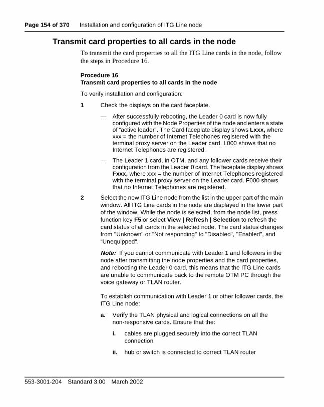
Page 154 of 370 Installation and configuration of ITG Line node
Transmit card properties to all cards in the nodeTo transmit the card properties to all the ITG Line cards in the node, follow the steps in Procedure 16.
Procedure 16Transmit card properties to all cards in the node
To verify installation and configuration:
1 Check the displays on the card faceplate.
— After successfully rebooting, the Leader 0 card is now fully configured with the Node Properties of the node and enters a state of “active leader”. The Card faceplate display shows Lxxx, where xxx = the number of Internet Telephones registered with the terminal proxy server on the Leader card. L000 shows that no Internet Telephones are registered.
— The Leader 1 card, in OTM, and any follower cards receive their configuration from the Leader 0 card. The faceplate display shows Fxxx, where xxx = the number of Internet Telephones registered with the terminal proxy server on the Leader card. F000 shows that no Internet Telephones are registered.
2 Select the new ITG Line node from the list in the upper part of the main window. All ITG Line cards in the node are displayed in the lower part of the window. While the node is selected, from the node list, press function key F5 or select View | Refresh | Selection to refresh the card status of all cards in the selected node. The card status changes from "Unknown" or "Not responding" to "Disabled", "Enabled”, and “Unequipped".
Note: If you cannot communicate with Leader 1 and followers in the node after transmitting the node properties and the card properties, and rebooting the Leader 0 card, this means that the ITG Line cards are unable to communicate back to the remote OTM PC through the voice gateway or TLAN router.
To establish communication with Leader 1 or other follower cards, the ITG Line node:
a. Verify the TLAN physical and logical connections on all the non-responsive cards. Ensure that the:
i. cables are plugged securely into the correct TLAN connection
ii. hub or switch is connected to correct TLAN router
553-3001-204 Standard 3.00 March 2002
Installation and configuration of ITG Line node Page 155 of 370
iii. remote OTM can communicate with TLAN router
d. If remote OTM cannot communicate using the TLAN router, connect to the ITG Line card maintenance port and use the ITGL> CLI routeAdd command on each ITG Line card to add a new IP route, through the management gateway that points to the remote OTM PC subnet.
e. If the card is reset before OTM successfully transmits the card properties (containing the SNMP Manager IP addresses and the card routing IP addresses), then you must repeat step b.
3 If any of the cards are not status "disabled", go into Overlay 32 and disable the card in order to prepare to transmit card properties again to Leader 1 and follower cards.
4 When Leader 1 and follower cards all show a status of disabled, go into Configure | Synchronize | Transmit. When the Transmit window opens, click the Transmit to selected nodes radio button and the Card properties to all disabled cards check box to transmit the card properties.
5 Click Start transmit. Carefully monitor the progress to verify the card properties are successfully transmitted to every ITG Line card in the selected node identified by its TN.
6 Verify that all ITG Line cards in the node have established a signaling link to the Meridian 1 Call Server.
—————————— End of Procedure ——————————
Upgrade the ITG Line card software and i2004 Internet Telephone firmware
Before upgrading your software and firmware, check the version of card software and i2004 Internet Telephone firmware that is currently installed. Compare this to the latest versions available by accessing the Nortel Networks web site. Refer to Procedure 17 on page 157 for complete instructions.
When a software upgrade is required, go to the Nortel Networks web site to download the appropriate software. When Internet access is unavailable from the OTM PC, use a PC with Internet access and transfer the software files to the OTM PC for the following procedures.
ITG Line Description, Installation, and Operation
Page 156 of 370 Installation and configuration of ITG Line node
i2004 Internet Telephone firmware requirementsThe i2004 Internet Telephone has field upgradable firmware. A copy of this firmware is stored on each ITG Line card in the system to automatically upgrade i2004 Internet Telephones if an upgrade is required. All i2004 Internet Telephones in a system must use the same version of firmware as the ITG Line card.
The i2004 Internet Telephone uses Trivial File Transfer Protocol (TFTP) to transfer the firmware; therefore, the customer’s network must support TFTP. For example, the customer’s network cannot be blocked by a firewall.
Firmware upgrade from a new ITG Line cardWhen the ITG Line card is received from the factory, it has the latest i2004 firmware already installed in the C:/FW directory. As each i2004 Internet Telephone comes online, its firmware version is automatically compared to the version that is stored on the ITG Line card. If they are different, a process is started which downloads the new firmware from the ITG Line card to the i2004 Internet Telephones. After the new firmware has been downloaded, the i2004 reboots and registers again with the ITG Line card.
Note: The i2004 Internet Telephone will not necessarily register with the same card as before the upgrade occurred.
Verify card software and i2004 Internet Telephone firmwareBefore you beginEnsure that you have the following software installed on your PC:
• Software to extract zipped files (WinZip or equivalent)
• A web browser (such as Microsoft Internet Explorer or Netscape Navigator)
To verify the ITG Line card software and the firmware on the i2004 Internet Telephone, follow the steps in Procedure 17.
553-3001-204 Standard 3.00 March 2002

Installation and configuration of ITG Line node Page 157 of 370
Procedure 17Verify card software and i2004 Internet Telephone firmware
1 In the OTM Navigator, select the Services folder. Double-click on the ITG IP Phones icon. The ITG Telephony Gateway - IP Phones window opens. Select an ITG Line node in the upper part of the window. A list of all line cards for that node appears in the lower part of the window.
2 Starting with the Leader 0 ITG Line card, double-click each ITG Line card in the list to open the ITG Card Properties window.
3 Leave the default selection of the ITG Line card in the ITG Card Properties window, and click the Configuration tab. The current ITG Line card software and i2004 firmware versions are displayed on this tab as follows:
• The Line card software is labelled S/W version
• The i2004 Internet Telephone firmware is labelled IP Phone F/w version
4 Write down the ITG Line card software and i2004 Internet telephone firmware release of each ITG Line card for comparison against the latest recommended software release.
5 Check the Nortel Networks Customer Support web site for the latest software and firmware releases:
a. Connect to the following URL using any PC with Internet access: http://www.nortelnetworks.com
b. Point at the Customer Support link from the menu on the left of the screen. Click on Software Distribution from the pop-up menu. The Software Downloads page appears.
c. On the Software Downloads page, under the blue Product Selection bar on the right, click the View by a Product link. The Product Select page opens.
d. On the Product Select page, select Meridian Internet Telephony Gateways from the drop-down list, and click Save. The Software Downloads page opens with the Active product: Meridian Internet Telephony Gateways product list displayed.
e. Under the Images, Loads and Releases section, there is an All Software Types drop-down list. Select ITG Line from the list. The Software Downloads page refreshes and displays the ITG Line products.
ITG Line Description, Installation, and Operation

Page 158 of 370 Installation and configuration of ITG Line node
f. Click ITG Line 2.2 Software (2.2.xx).
g. If you are not already logged into your My Nortel Networks account, enter your User ID and Password on the Sign In page and then click Sign In.
Note: If you are not registered to access this web site, refer to the Meridian 1 or Succession CSE 1000 product bulletin for directions on how to register.
h. Once you are logged in, ignore the security alert.
i. The Software Downloads: Software Details Information page appears. Click the link next to File Download.
j. In the Save As window, choose the desired path to save the file to local disk on your PC and click Save.
k. Locate the saved file and double-click the *.zip file. The zipped file opens in a compression utility program and the uncompressed files are listed.
Note: The *.mms file is the ITGL application and fwfile.1 is the i2004 Internet Telephone firmware.
6 Compare the latest software and firmware versions available with the software and firmware version of the CD-ROM shipped with the ITG Line/i2004 Internet Telephone.
7 If the CD-ROM is not up-to-date, transfer the downloaded software files (*.mms and fwfile.1) from an Internet-enabled PC to the OTM PC. Upgrade the ITG Line card(s) with the software and firmware files downloaded from the Nortel Networks Customer Service Software Distribution web site.
8 If the CD-ROM software and firmware is up-to-date, do not upgrade your ITG Line cards from the web. Install the software and firmware from the CD-ROM onto the ITG Line card/i2004 Internet Telephone when prompted by OTM.
Refer to Procedure 18, “Upgrade ITG Line card software from the web” on page 160, and Procedure 19, “Upgrade i2004 Internet Telephone firmware” on page 162 for detailed instructions on how to perform the upgrades.
—————————— End of Procedure ——————————
553-3001-204 Standard 3.00 March 2002
Installation and configuration of ITG Line node Page 159 of 370
Once you have verified the ITG Line card software and i2004 Internet Telephone firmware, there are three upgrade options:
1 Upgrade the ITG Line card software–Procedure 18 only
You may have to upgrade the ITG Line card software only. This option is used most frequently; however, verify if an Internet Telephone firmware upgrade is also required.
2 Upgrade both the ITG Line card software and the i2004 Internet Telephone firmware–Combination of Procedure 18 and Procedure 19
You have to upgrade both the ITG Line card software and the i2004 Internet Telephone firmware.
Note: Defer restarting the Line cards until the end of Procedure 19, as restarting the cards restarts all the phones.
3 Upgrade the i2004 Internet Telephone firmware–Procedure 19
You may only have to upgrade the i2004 Internet Telephone firmware.
Note: In this case, you must restart all phones instead of all cards. To do this, select a single test telephone and reset the software only on that test telephone before completing the procedure on all phones. If the software upgrade works properly, use the umsUpgradeAll command to complete the upgrade on all the phones.
Upgrade ITG Line card software from the webTo upgrade the software on the ITG Line card, follow the steps in Procedure 18 on page 160.
If you just completed Procedure 17, you should have obtained and verified the correct software for the ITG Line card, and transferred the files to the OTM PC.
ITG Line Description, Installation, and Operation
Page 160 of 370 Installation and configuration of ITG Line node
Procedure 18Upgrade ITG Line card software from the web
1 Open the OTM Navigator, and click on the Services folder. Double-click the ITG IP Phones icon. The IP Telephony Gateway - IP Phones window opens.
2 Select the ITG Line cards that are to be upgraded from the main card list view. Upgrade all the cards in the node together, unless you are installing a spare card that has older software.
3 Disable all ITG Line cards to be upgraded. Use the Meridian 1 Overlay 32 DISI command from OTM Maintenance Windows, the OTM System Passthru terminal, or from a Meridian 1 system management terminal directly connected to a TTY port on the Meridian 1.
4 In the IP Telephony Gateway - IP Phones main window, select View | Refresh and verify that the card status is showing “Disabled.”
5 Select Configuration | Synchronize | Transmit. The “ITG - Transmit Options” dialog box is displayed.
6 Under Transmit options, select the Transmit to selected cards radio button.
7 Under Software download, click the Card software check box.
8 Click on the Browse button to the right of the Software location text box. Locate the ITG Line card software that you verified to be the correct version in Procedure 17 on page 157.
Select the software file and click Open to save the selection. The path and file name of the ITG Line card software appears in the Software location text box.
9 Click Start transmit to begin the ITG Line card software upgrade process.
The software is transmitted to each card in turn, and burned into the flash ROM on the ITG Line card.
10 Monitor progress in the Transmit control window. Confirm that the card software is transmitted successfully to all cards. Note any error messages, investigate, correct any problems, and repeat card software transmission until it is completed successfully on each ITG Line card. The cards continue to run the old software until they are rebooted.
553-3001-204 Standard 3.00 March 2002

Installation and configuration of ITG Line node Page 161 of 370
11 Reboot each ITG Line card that received transmitted software. This enables the new software to take effect. Reboot Leader 0 first, followed by the other cards.
Note: These cards must remain in the “Disabled” state after the upgrade, so that the technician can issue a “Reset” command from the Maintenance menu. Alternatively, click the Reset button on the Maintenance tab in the ITG Card Properties window of each card to reboot them. Also, the cards can be reset by using a pointed object to press the “Reset” button on the card faceplate.
12 After all ITG Line cards have been reset, have successfully rebooted, and are responding again to the OTM ITG Line Application, do a Status refresh (disabled: active; disabled: backup; disabled).
13 Double-click each upgraded card and verify the software version on the Configuration tab of the ITG Card Properties.
14 Use the Overlay 32 ENLC command to re-enable the ITG Line cards.
Use LD 32 in the TTY or OTM Overlay passthru to enable the ITG Line cards with one of the following commands:
• ENLC l s c. (for Meridian 1 and Succession CSE 1000)
• ENLC c (for Option 11C or Option 11C-Mini)
15 Repeat the steps 14 and 15 above for each ITG Line card.
—————————— End of Procedure ——————————
Upgrade i2004 Internet Telephone firmwareWhenever the ITG Line Application has been upgraded you must verify whether or not there is a Internet Telephone firmware upgrade that is also required. Check the Release Notes for the ITG IP Phones application to determine which Internet Telephone firmware version is required to be compatible.
• In Procedure 17 on page 157, you should have obtained and verified the correct software for the ITG Line card, and transferred the files to the OTM PC.
ITG Line Description, Installation, and Operation
Page 162 of 370 Installation and configuration of ITG Line node
• If using Procedure 18 on page 160 and Procedure 19 on page 162 together, do not restart the Line card until Procedure 20 is completed. You must reset all the cards because the software has not been upgraded. The new software will not run until the cards are rebooted, because the new firmware may be incompatible with the old software.
• If using Procedure 20 alone, that is, a firmware upgrade, it is only necessary to reboot the node.
To upgrade the firmware on the i2004 Internet Telephone, follow the steps in Procedure 19. This procedure has two major steps:
• placing the Internet Telephone firmware onto each card in the node
• propagating the firmware from the card to each telephone registered on that card
Procedure 19Upgrade i2004 Internet Telephone firmware
1 Open OTM Navigator, and click the Services folder. Double-click the ITG IP Phones icon. The IP Telephony Gateway - IP Phones window opens.
2 Disable all ITG Line cards for upgrading from the main card list view. All cards must have the same Internet Telephone firmware version.
3 Verify that all ITG Line cards that require a firmware upgrade have established a signaling link with the Meridian 1 Call Server.
Note: You first need to disable ITG Line cards to update the firmware. Use the Overlay 32 DISI command from OTM Maintenance Windows, the OTM system Passthru terminal, or a Meridian 1 system management terminal directly connected to a TTY port on the Meridian 1.
To verify the link is available between the PBX and card, telnet to each card and login. From the command line, type pbxLinkShow. The status of the PBX link will appear. If the link is active the screen displays the following:
RUDPLinkState = Up
4 Select Configuration | Synchronize | Transmit. The ITG - Transmit Options dialog box is displayed.
553-3001-204 Standard 3.00 March 2002

Installation and configuration of ITG Line node Page 163 of 370
5 Under Transmit options, click the Transmit to selected node radio button.
6 Under Software download, check the EtherSet Firmware check box.
7 Click on the Browse button to the right of the Firmware location text box, to locate the Internet Telephone firmware that was previously verified to be required for the ITG Line card software version. Select the firmware file fwfile.1, and click Open. The path and file name of the Internet Telephone firmware appears in the Firmware location text box.
8 Click Start transmit to begin ITG Line upgrading the Internet Telephone firmware on the ITG Line cards.
9 Monitor progress in the Transmit control window. Confirm the card software is transmitted successfully to all cards. Note any error messages, investigate, correct any problems, and repeat card software transmission until it is completed successfully on each ITG Line card.
10 The i2004 Internet Telephones continue to run the old firmware until each telephone re-registers with an ITG Line card that contains the new Internet Telephone firmware.
Note: Commands are available from the ITGL command line to upgrade a single i2004 Internet Telephone immediately, all i2004 Internet Telephones immediately, or schedule all i2004 Internet Telephones to be upgraded at a later time. Before doing this, verify that each card has the correct firmware version and also check the date and time on the node.
11 Select a i2004 Internet Telephone for test purposes. Telnet to the ITG Line card. Login to the ITGL> command line, and enter the following:
iSetReset "xxx.xxx.xxx.xxx"
where xxx.xxx.xxx.xxx is the IP Address of the selected telephone.
CAUTIONDownloading an incorrect version of the Internet Telephone firmware may result in extended service interruptions and may require special recovery procedures.
ITG Line Description, Installation, and Operation

Page 164 of 370 Installation and configuration of ITG Line node
12 Monitor the display on the test telephone. As it upgrades the firmware, note the IP Address from which ITG Line card it is receiving its upgrade.
13 Press the Services key (key with globe with arrow pointing East and West) on the i2004 Internet Telephone. The Services key allows you to access the Telephony Options list.
Use the Navigation keys to scroll to Set Info.
Press the Select softkey, then press the Navigation keys until it displays FWVersion:. For the ITG Line card, select 3002B25.
Note: 3002B25 means Internet Telephone firmware version 1.25.
• 3002 represents the Internet Telephone
• B represents the Version number 1
• 25 represents the release number .25
14 Lift the handset and make a call to verify the telephone works.
When the telephone is working, verify the date and time on the node. Ensure each card has the correct software and IP Phone firmware before using the umsUpgradeAll command to upgrade all the telephones.
15 To verify the date and time on the node from OTM, select the node in the top of the IP Telephony Gateway - IP Phones window.
Double-click on Leader 0 in the bottom of the window. The ITG Card Properties window appears. The ITG Card Properties window has two tabs, Maintenance and Configuration.
Note: Cards receive their time from the leader card. If the time for Leader 0 is correct, all cards on the node should be the same. If Leader 0 displays the incorrect time, reset the time. The time propagates to the other cards.
16 Click the Maintenance tab. This displays the Node time. If the time is incorrect, click on the Set Node Time button. The Set Node Time window opens. Under Time and date, set the Time, where the time is displayed in the HH:MM:SS AM/PM format. Click OK to close the window.
553-3001-204 Standard 3.00 March 2002

Installation and configuration of ITG Line node Page 165 of 370
17 Click the Configuration tab. Note the card’s ITG software version (S/W version) and the IP Phone firmware version (IP Phone F/w version).
Double-click on each card to verify the software and firmware version. This must be done for every card.
18 Before proceeding, ensure the time of the card is set correctly. Telnet to each ITG Line card and login. At the ITGL> command line, enter the following:
umsUpgradeAll "hh:mma/p"
hh:mma/p specifies the time when the upgrade will occur, a represents A.M., and p represents P.M. The time is in Standard format.
For example, umsUpgradeAll “11:30a” or umsUpgradeAll “2:45p”.
At the time specified, all the i2004 Internet Telephones on the ITG Line card go out of service. This may take several minutes.
Upon completion of the firmware upgrade, the i2004 Internet Telephones are brought back online in groups of ten.
After the test telephone is working, the umsUpgradeAll does not need the time parameter. However, without the time parameter, the command immediately resets all the i2004 Internet Telephones currently registered on that line card.
If you do not immediately want to reset all the phones and you wish to schedule the reset time of the i2004 Internet Telephones, check the time on all the cards. Reset the time, if necessary, to ensure all cards have the same time, and then issue the umsUpgradeAll "hh:mma/p", where "hh:mma/p" represents the time when you want to schedule the upgrade to occur.
CAUTIONThe umsUpgradeAll command (without the time parameter) will cause the i2004 Internet Telephones registered on all cards you are logged into to be immediately taken out of service, unless the time parameter is specified.
ITG Line Description, Installation, and Operation
Page 166 of 370 Installation and configuration of ITG Line node
19 At the ITGL> prompt, verify the i2004 Internet Telephone are upgraded for each ITG Line card by entering the following:
isetShow
Inspect the list to ensure all i2004 telephones have a firmware version of 3002B25.
20 For any i2004 Internet Telephones which did not upgrade successfully, try one of the following (in order):
• use the isetReset ''IP Address'' command
• enter the following combination of key strokes at the telephone console: release, mute, up, down, up, down, up, mute, 9, release
• power the telephone off and then on again
If the upgrade was unsuccessful on any of the i2004 Internet Telephones, this is most likely due to one of the following reasons:
• one of the ITG Line cards did not upgrade the software successfully
• an i2004 Internet Telephone is loaded with a firmware version that was unable to be upgraded by the ITG Line card in the normal way
• you may have forgotten to issue the umsUpgradeAll command
• you may have missed resetting one of the cards
If the upgrade was unsuccessful, re-do the appropriate procedure. If the upgrade is still unsuccessful, contact your technical support representative for further assistance.
—————————— End of Procedure ——————————
For additional information on configuring the i2004 Internet Telephone and the i2050 Software Phone, see Internet Terminal: Description Guide (553-3001-217).
553-3001-204 Standard 3.00 March 2002

Installation and configuration of ITG Line node Page 167 of 370
Configure OTM alarm notification to receive ITG Line SNMP traps
To configure the alarm notification feature in OTM to receive SNMP traps, follow the steps in Procedure 20.
Procedure 20Configure SNMP Traps
1 In the OTM Navigator window, select the Utilities menu option and then click on Alarm Notification. The OTM Alarm Notification window appears (see Figure 20 on page 168).
2 Select Configuration | Run Options.
The Alarm Notification Run Options dialog box appears (see Figure 21 on page 169).
3 Click the Control Files tab (see Figure 22 on page 170).
4 Click the Browse button located to the right of the Devices text box. The Open dialog box appears.
5 Select the Devices file from the Control Files folder and click Open (see Figure 23 on page 171). The Devices.txt file opens (see Figure 24 on page 171.
6 For each ITG Line card in each monitored ITG Line node, add a line consisting of three fields separated by spaces, as shown in Table 29 on page 172. Enter the first line under the last line that begins with a "#".
7 Click File | Save As. Save the template to a new file, for example, ITGDevices1.txt, so you do not overwrite the template file.
8 In the Alarm Notification Run Options window, verify that the devices field name is correct (ITGDevices1.txt). Click Apply, and then OK.
Note: OTM Alarm Notification must be restarted whenever Control Files are changed.
ITG Line Description, Installation, and Operation

Page 168 of 370 Installation and configuration of ITG Line node
9 If OTM Alarm Notification is running, that is, the red traffic light is showing on the tool bar, first stop it by clicking on the red traffic light. The traffic light changes to green on the toolbar. Restart it by clicking on the green traffic light. The traffic light should turn back to red to indicate it is running again.
If OTM Alarm Notification is not running, as indicated by the green traffic light showing on the tool bar, click on the green traffic light to change it to red. This starts Alarm Notification.
10 Telnet to each Line card, login and at the ITGL> command line, enter the itgAlarmTest command. A series of SNMP traps is emitted by the ITG Line card and appears in the OTM Alarm Notification browser window. Verify the device name identifies the correct ITG Line card.
—————————— End of Procedure ——————————
Figure 20OTM Navigator–Utilities | Alarm Notification
553-3001-204 Standard 3.00 March 2002

Installation and configuration of ITG Line node Page 169 of 370
Figure 21Alarm Notification Run Options–General tab
ITG Line Description, Installation, and Operation

Page 170 of 370 Installation and configuration of ITG Line node
Figure 22Alarm Notification Run Options–Control Files tab
553-3001-204 Standard 3.00 March 2002

Installation and configuration of ITG Line node Page 171 of 370
Figure 23Open dialog box
Figure 24Devices.txt file
ITG Line Description, Installation, and Operation
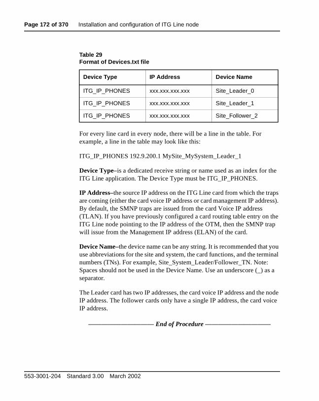
Page 172 of 370 Installation and configuration of ITG Line node
For every line card in every node, there will be a line in the table. For example, a line in the table may look like this:
ITG_IP_PHONES 192.9.200.1 MySite_MySystem_Leader_1
Device Type–is a dedicated receive string or name used as an index for the ITG Line application. The Device Type must be ITG_IP_PHONES.
IP Address–the source IP address on the ITG Line card from which the traps are coming (either the card voice IP address or card management IP address). By default, the SMNP traps are issued from the card Voice IP address (TLAN). If you have previously configured a card routing table entry on the ITG Line node pointing to the IP address of the OTM, then the SMNP trap will issue from the Management IP address (ELAN) of the card.
Device Name–the device name can be any string. It is recommended that you use abbreviations for the site and system, the card functions, and the terminal numbers (TNs). For example, Site_System_Leader/Follower_TN. Note: Spaces should not be used in the Device Name. Use an underscore (_) as a separator.
The Leader card has two IP addresses, the card voice IP address and the node IP address. The follower cards only have a single IP address, the card voice IP address.
—————————— End of Procedure ——————————
Table 29Format of Devices.txt file
Device Type IP Address Device Name
ITG_IP_PHONES xxx.xxx.xxx.xxx Site_Leader_0
ITG_IP_PHONES xxx.xxx.xxx.xxx Site_Leader_1
ITG_IP_PHONES xxx.xxx.xxx.xxx Site_Follower_2
553-3001-204 Standard 3.00 March 2002
Installation and configuration of ITG Line node Page 173 of 370
Configure security for SNMP accessProcedure 21 explains how to change the SNMP community names. This provides better security for the ITG Line node. OTM uses the community name password to refresh the ITG Line card status, and to control the transmitting and retrieving of configuration data files for database synchronization.
Note: If you forget the community names, connect a TTY to the ITG Line card maintenance port. Restart the card. The card displays the community name on the TTY during startup.
To configure the SNMP community names, follow the steps in Procedure 21.
Procedure 21Configuring security for OTM SNMP access
1 Click the Security tab (see Figure 25 on page 174)
2 Change the default Read only and Read/write community names.
OTM uses the Previous Read/write community name to transmit the card properties. The first time you transmit data after changing the password, the Previous Read/write password is used. For all following data transmissions, the changed password is used.
3 Click Apply.
—————————— End of Procedure ——————————
ITG Line Description, Installation, and Operation

Page 174 of 370 Installation and configuration of ITG Line node
Figure 25New ITG Node–Security tab
Changing the ITGL> CLI shell user name and passwordThe ITGL> Command Line Interface (CLI) is password protected for Telnet access and access to the local maintenance port. The same user name and password also protects FTP access to the ITG Line card.
The ITGL> CLI has a default user name of itgadmin and a default password of itgadmin. Change the default user name and password as a preventative security measure. Periodically changing the user name and password is a good security policy. The shellPasswordSet command changes the ITG Line username and password.
To change the user name and password of the ITGL> Command Line Interface, follow the steps in Procedure 22 on page 175.
WARNINGDo not leave the ITGL> CLI shell user name and password as the default.
553-3001-204 Standard 3.00 March 2002

Installation and configuration of ITG Line node Page 175 of 370
Procedure 22Changing the ITGL> CLI shell user name and password
1 From the ITGL> CLI, use the command shellPasswordSet to change the default user name and password.
The default user name is itgadmin and the default password is itgadmin.
2 You will be prompted as follows:
Enter current user name: itgadminEnter current password: itgadminEnter new user name: newnameEnter new password: newpwdEnter new password again to confirm: newpwd
Note: The new password must be 8 to 12 characters in length. You should not re-use the default user name and password.
If the entire sequence of commands is successfully entered, the system response is 'value = 0 = 0x0'. The new user name and password are now stored in non-volatile RAM on the ITG Line card, and will be retained even if the card is reset, powered-off, or powered-on.
—————————— End of Procedure ——————————
ITG Line Description, Installation, and Operation
Page 176 of 370 Installation and configuration of ITG Line node
Configure the Internet Telephone Installer PasswordsInternet Telephone Installer Password
An Internet Telephone displays the Node ID and the Terminal Number (TN) of the telephone for five seconds as the telephone boots up. The Internet Telephone Installer Password protection, for changing the TN on the telephone, controls registration with a virtual line TN on the Call Server (see page 32).
The Internet Telephone Installer Password is set and administered using a set of six ITGL> CLI commands (see Table 45 on page 278).
When an ITG Line node is first installed, the administrative password and the temporary password are not defined. The password feature is in the disabled state. The nodePwdSet command sets and enables the password.
If the nodePwdEnable command is entered before setting the password using the nodePwdSet command, the password is enabled with a null password. If enabled with a null password, the password and TN prompts are never displayed on the Internet Telephones.
When the password is enabled and configured, the screen on the Internet Telephone displays the four digit Node ID and a Password prompt, instead of the Node ID and TN fields.
The Internet Telephone Installer Passwords are configured on one ITG Line card in the node. The passwords are then applied to all cards in the node.
To configure the administrative Internet Telephone Installer Password, follow the steps in Procedure 23 on page 177. To configure the temporary Internet Telephone Installer Password, refer to the steps in Procedure 24 on page 179.
553-3001-204 Standard 3.00 March 2002

Installation and configuration of ITG Line node Page 177 of 370
Procedure 23Configure the administrative Internet Telephone Installer Password
1 Connect to any ITG Line card in the node.
2 Login to the ITGL> CLI and type the nodePwdShow command. This command displays the settings of the Internet Telephone Installer (node) password.
If in the default state, the Internet Telephone Installer Password has never been set, the nodePwdShow command should display the following:
where:
NodeID–the Internet Telephone Installer Password configuration applies to all ITG Line cards on the same TLAN that belong to this Node ID.
PwdEna–by default the cards should be in disabled state (PwdEna=No). The PwdEna setting specifies the enabled (Yes) or disabled (No) state of the Internet Telephone Installer Password.
Pwd–this is the administrator Internet Telephone Installer Password. In the default state, the administrator password is null.
TmpPwd–this is the temporary Internet Telephone Installer Password. In the default state, the temporary password is null.
Uses–the Uses parameter applies to the temporary Internet Telephone Installer Password. In the default state, this setting is null. If the card is not in the default state, the Uses parameter is a numeric value from 0-1000. This number specifies the remaining number of uses for the temporary password. If zero is entered for the Uses parameter when setting the temporary password, the Time parameter is mandatory. As a result, the password expires based on time instead of a number of uses.
Timeout–the Timeout heading corresponds to the Time parameter of the temporary Internet Telephone Installer Password. In the default state the Time is null. If the card is not in the default state, this setting specifies the duration in hours in which the temporary password is valid. The range is 0-240 hours (which is a maximum of 10 days). The number specified under Timeout indicates the remaining time to expiry
NodeID=======123
PwdEna========No
Pwd=========
TmpPwd=========
Uses========
Timeout==========0d 0h 0m 0s
ITG Line Description, Installation, and Operation

Page 178 of 370 Installation and configuration of ITG Line node
of the temporary password. The Time parameter is optional if the Uses parameter is non-zero and it is mandatory if Uses is set to zero.
Note: If both the Uses and Time parameters are entered, the password expires on whichever comes first, that is, Uses is reduced to zero or the Time has expired. If both Uses and Time are entered and are set to zero, it is the same as not setting the temporary password.
Next set the administrator Internet Telephone Installer Password. The nodePwdSet “password” commands enables and sets the administrator password. The “password” parameter can be null, or 6 to 14 digits in length. The valid characters are 0-9 * #. This command can be entered at any time. The new password entered simply overwrites the previous password.
Set the administrator password, first with a null password and then with a password specified.
3 Type nodePwdSet at the ITGL> prompt. Note no password parameter is specified.
4 Type nodePwdShow to see the following:
PwdEna–the administrator password is now enabled (PwdEna=Yes).
Pwd–with no “password” parameter specified the administrator password is null. Internet Telephones cannot be installed when the password is null. A null password causes the Node ID and Password screen to be skipped during restart.
NodeID=======123
PwdEna========Yes
Pwd=========
TmpPwd=========
Uses========
Timeout==========0d 0h 0m 0s
WARNINGThe nodePwdSet, with no parameter, by default enables the administrator password and sets a null (zero-length) password. Enabling the administrator password and setting a null password makes it impossible to install the Internet Telephones. Therefore, the password parameter must always be specified.
553-3001-204 Standard 3.00 March 2002
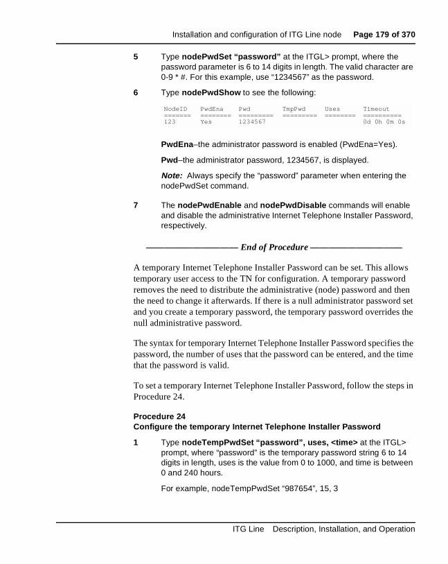
Installation and configuration of ITG Line node Page 179 of 370
5 Type nodePwdSet “password” at the ITGL> prompt, where the password parameter is 6 to 14 digits in length. The valid character are 0-9 * #. For this example, use “1234567” as the password.
6 Type nodePwdShow to see the following:
PwdEna–the administrator password is enabled (PwdEna=Yes).
Pwd–the administrator password, 1234567, is displayed.
Note: Always specify the “password” parameter when entering the nodePwdSet command.
7 The nodePwdEnable and nodePwdDisable commands will enable and disable the administrative Internet Telephone Installer Password, respectively.
—————————— End of Procedure ——————————
A temporary Internet Telephone Installer Password can be set. This allows temporary user access to the TN for configuration. A temporary password removes the need to distribute the administrative (node) password and then the need to change it afterwards. If there is a null administrator password set and you create a temporary password, the temporary password overrides the null administrative password.
The syntax for temporary Internet Telephone Installer Password specifies the password, the number of uses that the password can be entered, and the time that the password is valid.
To set a temporary Internet Telephone Installer Password, follow the steps in Procedure 24.
Procedure 24Configure the temporary Internet Telephone Installer Password
1 Type nodeTempPwdSet “password”, uses, <time> at the ITGL> prompt, where “password” is the temporary password string 6 to 14 digits in length, uses is the value from 0 to 1000, and time is between 0 and 240 hours.
For example, nodeTempPwdSet “987654”, 15, 3
NodeID=======123
PwdEna========Yes
Pwd=========1234567
TmpPwd=========
Uses========
Timeout==========0d 0h 0m 0s
ITG Line Description, Installation, and Operation

Page 180 of 370 Installation and configuration of ITG Line node
2 Type nodePwdShow to see the following:
3 The temporary password automatically deletes itself after it has been used the defined number of times (Uses) or when the duration expires (Timeout), whichever comes first. However, to delete the temporary password before the number of uses or time has expired, type nodeTempPwdClear command at the ITGL> prompt.
4 Type nodePwdShow to ensure the temporary password has been deleted.
—————————— End of Procedure ——————————
NodeID=======123
PwdEna========Yes
Pwd=========1234567
TmpPwd=========987654
Uses========15
Timeout==========0d 3h 0m 0s
NodeID=======123
PwdEna========Yes
Pwd=========1234567
TmpPwd=========
Uses========
Timeout==========0d 0h 0m 0s
553-3001-204 Standard 3.00 March 2002

Page 181 of 370
186
OTM setup to manage ITG Line nodesContents
This section contains information on the following topics:
Overview . . . . . . . . . . . . . . . . . . . . . . . . . . . . . . . . . . . . . . . . . . . . . . . . 181
OTM Engineering rules for ITG Line . . . . . . . . . . . . . . . . . . . . . . . . . . 182
Network setup guidelines . . . . . . . . . . . . . . . . . . . . . . . . . . . . . . . . . . . 182
Remote Access configuration . . . . . . . . . . . . . . . . . . . . . . . . . . . . . . . . 183
PC description . . . . . . . . . . . . . . . . . . . . . . . . . . . . . . . . . . . . . . . . . . . . 184
PC hardware and software requirements . .. . . . . . . . . . . . . . . . . . . . . . 185Hard drive requirements . . . . . . . . . . . . . . . . . . . . . . . . . . . . . . . . . . 186
OverviewThis section provides guidelines for setting up OTM 1.2 to support the ITG Line 2.2 application on the Meridian 1 and Succession CSE 1000 systems. The ITG Line card in turn supports i2004 Internet Telephones and i2050 Software Phones. The OTM 1.2 application for managing ITG Line nodes is called ITG IP Phones.
ITG Line Description, Installation, and Operation

Page 182 of 370 OTM setup to manage ITG Line nodes
OTM Engineering rules for ITG LineITG IP Phones can manage multiple ITG Line nodes. The maximum number of ITG Line nodes and cards that can be configured depend on the following:
1 All OTM ITG Line data is stored in a single database file. The entire database is read into PC memory when you launch the program. If a large ITG Line network is to be managed from a single OTM server, then each client must have more than 32 Mb of RAM. If the data is stored on a OTM server, the application launch time increases as the size of the ITG Line network grows (this also depends on the network speed).
2 A single OTM installation can support up to 500 Meridian 1 and Succession CSE 1000 systems. The real-time performance will be impacted by the tracking analysis or CDR billing analysis. Consult the OTM documentation for more information.
3 OTM Alarm Notification can receive a maximum of 20 SNMP traps for each second (based on the recommended PC configuration). In large networks, it is recommended that multiple OTM PCs be used to collect traps from ITG Line cards, each PC supporting one or more ITG Line nodes. Alarm notification scripts can be used to forward critical alarms to a central OTM PC or Network Management application.
Network setup guidelinesOTM can be installed in a standalone mode where it is installed on a single system. The files are stored on the same system as the OTM application. In this case, it is normally connected to the ELAN. OTM is able to access the remote ELAN using the CLAN.
For ITG Line and trunks, install OTM in a network environment, so you can manage multiple ITG Line nodes, provide multi-user access, and maintain ITG Line configuration data consistency, such as TN assignments and IP address assignments. In the network environment, OTM stores databases on a file server. Since OTM can manage multiple systems, it is recommended that you install OTM in a networked environment. A single OTM instance can manage multiple systems, or multiple instances of OTM can manage one or more systems.
553-3001-204 Standard 3.00 March 2002

OTM setup to manage ITG Line nodes Page 183 of 370
Do not use the server to access OTM as a client PC. OTM with Windows 95 or Windows NT 4.0 clients are supported on the following:
• Novell 3.12 or later server
• Windows NT server
• OTM 1.2 client requires an OTM server
Remote Access configurationSupport for remote access varies according to the support organization’s access to the customer’s data network LAN or WAN. There are three possible remote access scenarios. Refer to Figure 26 on page 184 for an illustration of remote access configuration.
• Customer provides an authenticated RAS account to all ELANs and router interfaces for full access to the customer’s network.
• Install dial-up modem routers on the ELANs and configure access to the customer’s TLAN in a secure manner.
• Connect an ordinary dial-up modem to the ITG Line card serial port for limited access to the ITG Line card configuration using ITGL> Command Line Interface (not OTM). This provides a read-only solution. There is no file transfer capability, as you can only display the command.
ITG Line Description, Installation, and Operation
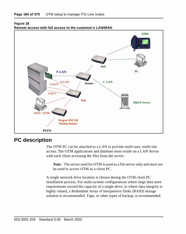
Page 184 of 370 OTM setup to manage ITG Line nodes
Figure 26Remote access with full access to the customer’s LAN/WAN
PC descriptionThe OTM PC can be attached to a LAN to provide multi-user, multi-site access. The OTM applications and database must reside on a LAN Server with each client accessing the files from the server.
Note: The server used for OTM is used as a file server only and must not be used to access OTM as a client PC.
A single network drive location is chosen during the OTM client PC installation process. For multi-system configurations where large data store requirements exceed the capacity of a single drive, or where data integrity is highly valued, a Redundant Array of Inexpensive Disks (RAID) storage solution is recommended. Tape, or other types of backup, is recommended.
T-LAN
E-LANCore 0
Core 1
MAT / OTM
PSTN
Netgear RM 356Modem Router
Hub
Router
Hub
PC
I2004
DHCP Server
C -LAN
553-3001-204 Standard 3.00 March 2002

OTM setup to manage ITG Line nodes Page 185 of 370
When you install OTM client applications, map the network drive the same way from each PC. This enables an OTM user to be able to log into the network with their network login ID at any OTM client PC.
A PC security device is required for every PC running OTM. A security device is not required for the PC server as it is only used to store OTM data. The PC server does not actually run any OTM applications.
Each of the OTM client PCs on the customer LAN is allowed connectivity to IP addresses of the Meridian 1 and Succession CSE 1000 as follows:
1 OTM client PC in a switchroom (on the ELAN subnet) has access to the File Server on the customer network.
2 Block broadcast messages from the C-LAN to the ELAN.
3 Block access to the ELAN from non-OTM client PCs for security reasons.
PC hardware and software requirementsThe minimum PC hardware and software requirements to run OTM are as follows:
• A Pentium Processor PC with:
— 100 MHz or faster CPU
— One GB or larger hard disk drive with 500 MB or more free space (includes Windows 95/NT 4.0 requirements). Please refer to system datastore column in Table 30 on page 186:
• 32 MB RAM (minimum)
• SVGA color monitor and interface card (800x600 resolution for graphics)
• 3-1/2 inch 1.44 MB floppy disk drive
• Windows 95 or Windows NT 4.0 with Microsoft TCP/IP installed
• Ethernet Network Interface Card
• Hayes-compatible modem is optional to connect to remote systems, required for polling configurations (9600 bps or better is recommended)
• PC COM port with 16550 UART
ITG Line Description, Installation, and Operation

Page 186 of 370 OTM setup to manage ITG Line nodes
• Parallel printer port. Configure a printer even through it is not required to be attached to the PC.
• Two-button Windows compatible mouse or positioning device
• CD-ROM drive
Note: Other applications launched while you use OTM can require increased RAM
Hard drive requirementsFor a single OTM PC configuration, refer to Table 30 to select the hard drive space required on the OTM PC. Consider both program and data store requirements.
For OTM client configurations (two or more OTM PCs sharing the same database), the common data is stored on a server PC that does not run OTM. Estimate the size of the required disk space on this server using the Data Store column in Table 30.
Table 30Hard drive capacity for OTM applications
OTM application Program store Data store
Common services (required) 38 MB Negligible.
ITG Line Internet Telephone 1.5 MB 1.0 MB plus 0.5 MB for each 1k ITG Line cards
Traffic Analysis 5 MB Meridian 1 and Succession CSE 1000 dependent: Typically 2.5 to 9 MB a month for each system traffic data.
ESN 1 MB Meridian 1 and Succession CSE 1000 dependent: Allow 1 MB for each customer.
Maintenance Windows 1 MB Negligible.
Alarm Management with Alarm Notification
1.5 MB Negligible.
553-3001-204 Standard 3.00 March 2002
Page 187 of 370
242
ITG Line application administrationContents
This section contains information on the following topics:
Overview . . . . . . . . . . . . . . . . . . . . . . . . . . . . . . . . . . . . . . . . . . . . . . . . 188
OTM administration procedures . . . . . . . . . . . . . . . . . . . . . . . . . . . . . . 189ITG Line operational measurement report scheduling and generation . . . . . . . . . . . . . . . . . . . . . . . . . . . . . . . . . . . . . . . . . 189View ITG Line information and error log . . . . . . . . . . . . . . . . . . . . 196
Back up and restore OTM data . . . . . . . . . . . . . . . . . . . . . . . . . . . . . . . 196
Password Security . . . . . . . . . . . . . . . . . . . . . . . . . . . . . . . . . . . . . . . . . 197SNMP Community Names password . . . . . . . . . . . . . . . . . . . . . . . . 197Changing the ITGL> CLI Shell user name and password . . . . . . . . 198Resetting the ITGL> CLI Shell user name and password . . . . . . . . 198Internet Telephone Installer Password . . . . . . . . . . . . . . . . . . . . . . . 200Update ITG Line node properties . . . . . . . . . . . . . . . . . . . . . . . . . . . 201Add an ITG Line card to the node . . . . . . . . . . . . . . . . . . . . . . . . . . 202Delete an ITG Line card from the node . . . . . . . . . . . . . . . . . . . . . . 207Change the IP addresses of an ITG Line node in OTM . . . . . . . . . . 209
Update ITG Line card properties . . . . . . . . . . . . . . . . . . . . . . . . . . . . . 220Use the Retrieve command . .. . . . . . . . . . . . . . . . . . . . . . . . . . . . . . 226
Add an ITG LIne node in OTM by retrieving an existing node . . . . . . 228
ITG Line Command Line Interface access using Telnet or local RS-232 maintenance port . . . . . . . . . . . . . . . . . . . . . . . . . . . . . 233
Telnet to an ITG Line card . . . . . . . . . . . . . . . . . . . . . . . . . . . . . . . . 234Reset the operational measurements . . . . . . . . . . . . . . . . . . . . . . . . 234Display the number of DSPs . . . . . . . . . . . . . . . . . . . . . . . . . . . . . . 234
ITG Line Description, Installation, and Operation

Page 188 of 370 ITG Line application administration
Display ITG Line Node Properties . . . . . . . . . . . . . . . . . . . . . . . . . 234Display ITG Line card properties . . . . . . . . . . . . . . . . . . . . . . . . . . 235Transfer files using the Command Line Interface . . . . . . . . . . . . . . 236IP configuration commands . . . . . . . . . . . . . . . . . . . . . . . . . . . . . . . 238Configure TLAN parameters . . . . . . . . . . . . . . . . . . . . . . . . . . . . . . 238Packet loss monitor . . . . . . . . . . . . . . . . . . . . . . . . . . . . . . . . . . . . . 240Download the ITG Line error log . . . . . . . . . . . . . . . . . . . . . . . . . . 240Lamp audit and keep-alive function . .. . . . . . . . . . . . . . . . . . . . . . . 240
OverviewThis chapter explains how to administer the Meridian 1 and Succession Communication Server for Enterprise 1000 Internet Telephony Gateway (ITG) Line card.
Administration procedures include activities such as monitoring system status, operational reports, performing upgrades, changing configuration, adding, changing, and removing cards. Administration does not include engineering, provisioning, initial installation and configuration, maintenance, or troubleshooting.
The ITG Line card provides three administration interfaces:
• Optivity Telephony Manager (OTM)
— Provides a graphical interface to the ITG Line card. Use OTM to Telnet to the card, install and upgrade software, configure alarm event reporting, view and update card property and configuration data, add new cards to a node, schedule reports and other related tasks.
• ITGL> Command Line Interface (CLI)
— Use the CLI to display card and node status, change passwords, check software version, view channel states, and other card information. The CLI is also used for expert level support and debug. The prompt for the CLI on the ITG Line card is ITLG>. Access the CLI through a direct serial connection to the I/O panel serial port, the Maint Port on the faceplate, or through a Telnet session. Use a VT-100 terminal emulation program set to 9600 baud, 8 bits, no parity, one stop bit.
553-3001-204 Standard 3.00 March 2002
ITG Line application administration Page 189 of 370
• Meridian 1 and Succession CSE 1000 Overlays
— Use the same commands and messages for the ITG Line card as you would for any other Line card.
OTM administration proceduresThis section describes the OTM administration procedures you can perform using the OTM ITG IP Phones application. All of the references to OTM in the following procedures assume the latest OTM version.
For information on how to obtain the latest software versions and files, refer to “Installation and configuration of ITG Line node” on page 117.
ITG Line operational measurement report scheduling and generation
Operational Measurement (OM) reports provide important statistical and traffic information and feedback to the system administrator to better engineer the system. The information stored in the OM file applies only to the calls routed over the IP network by way of ITG Line. OM reports give a quantitative view of system performance, such as jitter.
The OM reports are a collection of data from all the ITG Line cards in the network. OM data is written to a file every hour. At midnight, the OM file is copied to a backup file, and the new day starts with a new file.
OTM uses the following naming convention for the OM file names:
itgIPPhone_MM_YYYY_file1.csv
An example is itgIPPhone_03_2000_file1.csv. This comma-delimited file opens in a program that interprets the .csv file, such as Microsoft Excel or any other comma-delimited file reader.
The user generates OM reports on demand or on a pre-selected schedule. When a report is generated, the application retrieves the latest OM data from each ITG Line card defined in OTM.
Under certain conditions, the OM report is not available:
• the first hour after a ITG Line card reboot
• the first hour after installing a new ITG Line card
ITG Line Description, Installation, and Operation
Page 190 of 370 ITG Line application administration
The following error messages are generated when requesting the OM report during the first hour:
• on OTM: "fails to transfer the OM file"
• on the ITG Line card console: "tfxl: Error File C:/OM/omreport.xxx not found"
Note: Nortel Networks recommends that you schedule report generation once a day.
To schedule a generated OM Report, follow the steps in Procedure 25.
Procedure 25Report scheduling
1 In the IP Telephony Gateway - IP Phones window, click on the node. Click File | Report. The Generate OM Report window opens.
2 In the Generate OM Report window there are two choices, Generate OM Report Now and Schedule OM Report.
Select the Schedule OM Report radio button.
3 Click OK. The Scheduling window appears (see Figure 27 on page 191).
4 Under Job, enter the Name and Description of the schedule.
5 Under Run, select the radio button that indicates the frequency of report generation.
6 Under Start at, enter the date and time of the start of the report period using the Month, Day, Year, Hour, and Minute list boxes and the am or pm radio buttons.
7 Under Start at, click the Late execution check box if you want to report to run at a later time in the event the system is busy at the scheduled time.
8 Click OK.
—————————— End of Procedure ——————————
553-3001-204 Standard 3.00 March 2002
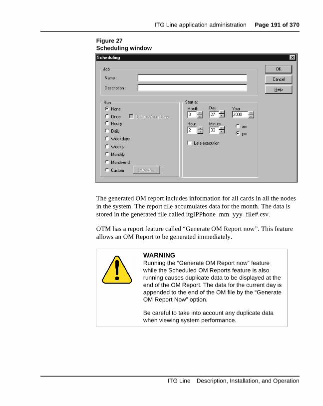
ITG Line application administration Page 191 of 370
Figure 27Scheduling window
The generated OM report includes information for all cards in all the nodes in the system. The report file accumulates data for the month. The data is stored in the generated file called itgIPPhone_mm_yyy_file#.csv.
OTM has a report feature called “Generate OM Report now”. This feature allows an OM Report to be generated immediately.
WARNINGRunning the “Generate OM Report now” feature while the Scheduled OM Reports feature is also running causes duplicate data to be displayed at the end of the OM Report. The data for the current day is appended to the end of the OM file by the “Generate OM Report Now” option.
Be careful to take into account any duplicate data when viewing system performance.
ITG Line Description, Installation, and Operation
Page 192 of 370 ITG Line application administration
To generate an OM Report immediately, follow the steps in Procedure 26.
Procedure 26Report generation
1 In the IP Telephony Gateway - IP Phones window, click the node. Click File | Report. The Generate OM Report window opens.
2 Click Generate OM Report now.
3 Click OK.
OTM creates and displays a report named ITG IP Phones - Operational Measurement Report. This report is a comma delimited file. The name of the generated file is itgIPPhone_mm_yyyy_file#.csv. The default file that is generated opens in Microsoft Excel. Therefore, Microsoft Excel or another comma-delimited reader must be installed on the PC.
—————————— End of Procedure ——————————
To open and view the OM Report file, follow the steps in Procedure 27.
Procedure 27Open an Operational Measurement (OM) report
1 In the IP Telephony Gateway - IP Phones window, select the node in the top of the window.
2 Click File | Report | Open. The Open OM Report window opens (see Figure 28 on page 193).
3 Select a report file and click Open. The file opens in a program that interprets .csv (comma-delimited) files such as Microsoft Excel. If you do not have Microsoft Excel installed on the PC you are directed to the location where the .csv file is located.
—————————— End of Procedure ——————————
553-3001-204 Standard 3.00 March 2002
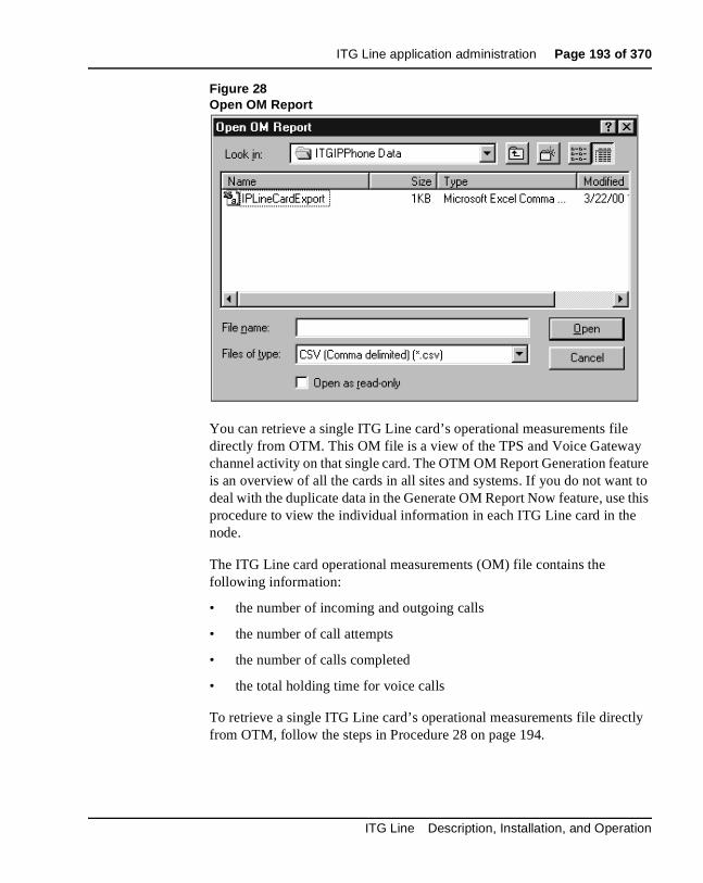
ITG Line application administration Page 193 of 370
Figure 28Open OM Report
You can retrieve a single ITG Line card’s operational measurements file directly from OTM. This OM file is a view of the TPS and Voice Gateway channel activity on that single card. The OTM OM Report Generation feature is an overview of all the cards in all sites and systems. If you do not want to deal with the duplicate data in the Generate OM Report Now feature, use this procedure to view the individual information in each ITG Line card in the node.
The ITG Line card operational measurements (OM) file contains the following information:
• the number of incoming and outgoing calls
• the number of call attempts
• the number of calls completed
• the total holding time for voice calls
To retrieve a single ITG Line card’s operational measurements file directly from OTM, follow the steps in Procedure 28 on page 194.
ITG Line Description, Installation, and Operation

Page 194 of 370 ITG Line application administration
Procedure 28Retrieve the current OM file from the ITG Line card using OTM
1 In the OTM Navigator window, click the Services folder. Double-click the ITG IP Phones icon. The IP Telephony Gateway - IP Phones window opens.
2 Select the node in the upper portion of the window. Select the ITG Line card from the lower portion of the window.
3 Right-click and then select Card | Properties from the pop-up menu. The ITG Card Properties window opens to the Maintenance tab.
4 Click the Open OM file button (see Figure 29 on page 195). A file called om.txt opens in the WordPad application. The file contains collection period information for each hour of the day that the card was running.
The collection periods start with the hour from midnight to 1:00am. OTM adds to the file each hour, so there will be a total 24 collection periods each day. A collection period looks like the following:
collection_time : 2/8/2002 9:00i2004Reg_Att: 1i2004Reg_Fail: 0i2004Unreg_Att: 0i2004Aud_Setup: 1i2004Jitter_Avg: 0.1i2004Jitter_Max: 0i2004Pkt_Lost: 0.00i2004Voice_Time: 0 mins 2 secsChanAud_Setup: 1ChanJitter_Avg: 6.0ChanJitter_Max: 20ChanPkt_Lost: 0.00ChanVoice_Time: 0 mins 2 secsNote: During this collection period, reboot(s) occured.
Each collection period provides the following:
• the date and time for the collection period hour.
• TPS information for Internet Telephones that are registered to the TPS on the ITG Line card during that hour. The TPS information is prefixed by i2004.
553-3001-204 Standard 3.00 March 2002
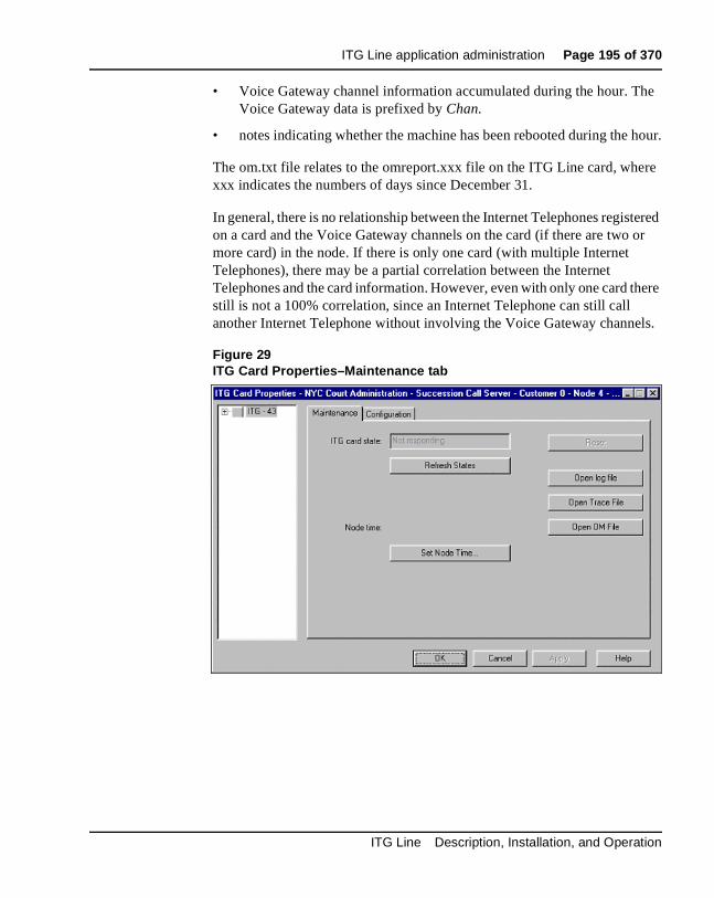
ITG Line application administration Page 195 of 370
• Voice Gateway channel information accumulated during the hour. The Voice Gateway data is prefixed by Chan.
• notes indicating whether the machine has been rebooted during the hour.
The om.txt file relates to the omreport.xxx file on the ITG Line card, where xxx indicates the numbers of days since December 31.
In general, there is no relationship between the Internet Telephones registered on a card and the Voice Gateway channels on the card (if there are two or more card) in the node. If there is only one card (with multiple Internet Telephones), there may be a partial correlation between the Internet Telephones and the card information. However, even with only one card there still is not a 100% correlation, since an Internet Telephone can still call another Internet Telephone without involving the Voice Gateway channels.
Figure 29ITG Card Properties–Maintenance tab
ITG Line Description, Installation, and Operation

Page 196 of 370 ITG Line application administration
View ITG Line information and error logOTM uses FTP to transfer the file from the ITG Line card to the PC. The file is opened in the WordPad application. The ITG Error log file displays error information, including error date/time, the originating module (ITG Line node), and specific error data.
To view ITG error conditions that are abnormal events, but not severe enough to raise an alarm, follow the steps in Procedure 29:
Procedure 29Viewing ITG info and error log
1 In the OTM Navigator window, click the Services folder. Double-click the ITG IP Phones icon. The IP Telephony Gateway - IP Phones window opens.
2 Right-click in the window. Select Card | Properties from the pop-up menu. The ITG Card Properties window opens to the Maintenance tab.
3 Click the Open log file button and review the file contents.
—————————— End of Procedure ——————————
Back up and restore OTM dataThe OTM Backup Wizard is used to backup and restore any or all OTM PC-based data, including ITG Line OTM data. All the ITG Line data is stored in an Access database file on the OTM PC or Server. This file is only backed up when the user selects the “Disaster Recovery” option. This option backs up all OTM data contained in the PC directory where OTM is installed and can only be used to restore all data.
For more information on using the OTM Backup Wizard, see the Common Services User Guide in the OTM User Guides.
553-3001-204 Standard 3.00 March 2002
ITG Line application administration Page 197 of 370
Password SecurityThere are three password security features:
1 SNMP Community Name Password
2 ITGL> CLI Shell Password
3 Internet Telephone Installer Password
The Internet Telephone Installer Password works at the node level. Both the SNMP Community Name password and the ITGL> CLI Shell password operate at the card level.
• The Internet Telephone Installer Password is first applied to one card in the node, and then is applied to all the cards in the node.
• The SNMP Community Name password is contained in the card properties that were transmitted to each card.
• The ITGL> CLI Shell password is set on each individual card.
SNMP Community Names passwordOTM requires the SNMP Community Names password to access the ITG Line card. There are two community names, Current and Previous (see Figure 25 on page 174). OTM stores both community names. The Previous community name is used to access the ITG Line card when changing to a community name.
Procedure 21 on page 173 explains how to change the SNMP community names to provide greater security for the ITG Line node.
ITG Line Description, Installation, and Operation

Page 198 of 370 ITG Line application administration
Changing the ITGL> CLI Shell user name and passwordGood security policy requires changing user names and passwords periodically. To change the ITGL> user name and password, follow the steps in Procedure 30.
Procedure 30Changing the ITGL> CLI Shell user name and password
Change the ITGL> CLI Shell user name and password if it was not changed during the installation of the ITG Line card. Never leave the default user name and password.
1 From the ITGL> CLI, use the command shellPasswordSet to change the current (or default) ITGL> CLI shell user name and password.
The default user name is itgadmin and the default password is itgadmin; however, this should have been changed during installation.
2 The prompts are displayed as follows:
Enter current user name: currentname (or itgadmin)Enter current password: currentpwd (or itgadmin)Enter new user name: <newname>Enter new password: <newpwd>Enter new password again to confirm: <newpwd>
If the entire sequence of commands is successfully entered, you get the system response with ’value = 0 = 0x0’. The new user name and password are now stored in non-volatile RAM on the ITG Line card. They are retained even if the card is reset, powered-off, or powered-on.
—————————— End of Procedure ——————————
Resetting the ITGL> CLI Shell user name and passwordIf the authorized system management personnel do not have the current ITGL> CLI Shell user name and password, reset the user name and password to default (itgadmin and itgadmin).
To reset the ITGL> CLI shell user name and password, follow the steps in Procedure 31. This procedure requires a connection to the local maintenance port on the ITG Line card and also requires rebooting the card which will interrupt services.
553-3001-204 Standard 3.00 March 2002
ITG Line application administration Page 199 of 370
Procedure 31Resetting the user name and password to default
1 Connect a terminal to the Maintenance port (labeled Maint) either directly or through a dial-up modem. The terminal communication parameter must be 9600bp, 8 data bits, no parity, and 1 stop bit.
2 Press the Enter key on the keyboard. The ITGL> prompt is displayed.
3 Reboot the card by pressing the RESET button on the faceplate of the card with a pointed object, such as a ball-point pen.
4 Start up messages are displayed on the terminal. Type jkl on the terminal keyboard when you see the prompt.
Note: jkl runs from bios or boot ROM which is printed early in the bootup process. There is only a six second window at the prompt to enter jkl. If you miss the prompt, restart the card and repeat the above step.
5 Once the card has booted from bios or boot ROM, a command line interface such as the BIOS> prompt appears. Enter the following command shellPasswordNvramClear at the prompt.
6 Type reboot at the prompt to reboot the card.
7 Allow the card to completely reboot into the ITG Line application.
8 Login using the default user name (itgadmin) and password (itgadmin).
9 Perform Procedure 30 on page 198 to change the ITGL> CLI user name and password.
Note: Never leave the default user name and password on a system that is in service. An effective security policy requires frequent change of the ITGL> CLI user name and password.
—————————— End of Procedure ——————————
WARNINGDo not use a pencil to reset the ITG Line card. The graphite carbon can create an electrical short circuit on the board.
ITG Line Description, Installation, and Operation

Page 200 of 370 ITG Line application administration
Internet Telephone Installer PasswordITG Line introduces the availability of password protection for changing the TN on the Internet Telephone. An Internet Telephone displays the Node ID and Terminal Number (TN) of the telephone for five seconds as the telephone boots up. If the Internet Telephone Installer Password is set, the screen displays a prompt for the Node ID and Password. For more information, see “Internet Telephone Installer Password” on page 32.
The Internet Telephone Installer Password is not defined or enabled by default. To prevent users from inadvertently reconfiguring the Node ID and TN on their Internet Telephones, enable the Internet Telephone Installer Password after the initial installation of the Internet Telephone and the system has been put into service.
The Internet Telephone Installer Password is set and administered using a set of ITGL> CLI commands (see Table 45 on page 278). The nodePwdSet “password” command sets and enables the password.
If the nodePwdEnable command is entered before the password is set using the nodePwdSet command, the password is also enabled with a null password.
The administrator normally uses the administrative Internet Telephone Installer Password if it is necessary to install a new telephone or change the configuration (Node ID and TN) of an existing telephone.
WARNINGThe nodePwdSet with no “password” parameter enables the administrator password and sets a null (zero-length) password. Enabling the administrator password and setting a null password makes it impossible to install the Internet Telephones because the Node ID and TN prompts are not displayed on the telephone screen.
Always specify the “password” parameter when issuing the nodePwdSet command. This password parameter is 6-14 digits in length. The valid characters are 0-9 * #.
553-3001-204 Standard 3.00 March 2002

ITG Line application administration Page 201 of 370
Note: If you are unable to install an Internet Telephone because you are not prompted for a Node ID and TN, login to an ITG Line card and check the status of the password using the nodePwdShow command.
The administrator can create a temporary Internet Telephone Installer Password for experienced users who are delegated to install Internet Telephones. If a null administrator password is set and a temporary password is created, the temporary password will override the null administrator password.
See Procedure 23 on page 177 and Procedure 24 on page 179 to set the Internet Telephone Installer Passwords.
If the administrator wishes to suppress all password prompting to reconfigure the Node ID and TN, then the temporary password should be cleared using the nodeTempPwdClear command. Also, set the administrative password to a null password using the nodePwdSet command with no “password” parameter specified.
Update ITG Line node propertiesTo update the node properties of an ITG Line card, follow the steps in Procedure 32.
Procedure 32Updating the ITG Line node properties
1 In the OTM Navigator window, select the Services folder. Double-click on the ITG IP Phones icon. The IP Telephony Gateway - IP Phones window opens.
2 Double-click on the node in the upper part of the window. The Properties window appears.
Perform all required updates to the General tab and Configuration tab parameters. The General and Configuration tabs are used to set the node properties. The other tabs affect the config.ini file and are also known as the card-affecting properties tabs. If you change any node or card property, you must transmit the configuration data to the node or the card.
ITG Line Description, Installation, and Operation
Page 202 of 370 ITG Line application administration
3 If you add, delete, or replace ITG Line cards from the node or change an ITG Line card (refer to the Maintenance section for the procedure to replace an ITG Line card), then use one of the following procedures:
• “Add an ITG Line card to the node” on page 202
• “Delete an ITG Line card from the node” on page 207
• “Change the IP addresses of an ITG Line node in OTM” on page 209
• “Replacing an ITG Line card” on page 250
—————————— End of Procedure ——————————
Add an ITG Line card to the nodeTo add an ITG Line card to the node, follow the steps in Procedure 33.
Procedure 33Add an ITG Line card to the node
1 Choose a card slot for the new card. Note the TN.
2 Configure IPTN in Meridian 1.
3 Install the I/O cables for connection to the ELAN and TLAN on the selected card slot.
4 In the OTM Navigator window, click the Services folder. Double-click on the ITG IP Phones icon. The IP Telephony Gateway - IP Phones window opens.
5 Double-click the node in the upper portion of the window, the ITG Node Properties window appears.
6 Click on the Configuration tab.
7 Enter the Card Properties data for Leader1 and the Followers:
a. Card role: Assign the Card role, Leader 0, to the first card you configure. For the remaining cards, assign the Card role as Follower.
b. Management IP: This is the ELAN IP address for the card. OTM and Meridian 1 and Succession CSE 1000 use this address to communicate with the card.
553-3001-204 Standard 3.00 March 2002

ITG Line application administration Page 203 of 370
c. Management MAC: This is the motherboard Ethernet address from your “ITG Line card installation summary sheet” on page 101.
d. Voice IP: This is the TLAN IP address for the card.
e. Voice LAN gateway IP: This is the IP address of the router interface on the TLAN.
f. Card TN: For Option 51C/61C/81/81C, enter Card TN (l s c) information. For Option 11C and 11C-Mini, enter only the card number between 0-50. The card TN format is determined by the Meridian 1 and Succession CSE 1000 system type which is configured in the OTM Navigator. Enter the correct system type in the OTM Navigator before you add the node.
g. Click Add. The card role and address information appears in a working list at the bottom of the New ITG Node window.
8 Click Apply to add the Card Properties to the Node.
9 If you have more cards, add them by repeating the steps above. Click OK when all the cards are added.
Prematurely clicking OK at this point, closes the window and saves any changes that were made. Double-click the new node in the upper part of the main ITG IP Phones window to re-open Node Properties and complete the configuration procedures.
10 Transmit the node properties. Login to Overlay 32. Disable the card in order to transmit the card properties.
11 In the OTM Navigator window, click the Services folder. Double-click on ITG IP Phones. The IP Telephony Gateway - IP Phones window opens.
12 From this list of ITG Line nodes in the upper part of the window, select the ITG Line node to which you want to transmit configuration data.
13 Click the Configuration | Synchronize | Transmit. The ITG - Transmit Options window appears.
14 Keep the default setting of Transmit to selected nodes radio button. Check only the Node Properties to Active Leader check box (see Figure 30 on page 206).
15 Click the Start transmit button. Monitor progress under Transmit Control window. Confirm that the node properties are transmitted successfully to Leader 0.
ITG Line Description, Installation, and Operation

Page 204 of 370 ITG Line application administration
16 When the transmission is complete, click the Close button.
17 Choose a card slot for the new card. Note the TN. Configure IPTN in Meridian 1 (see Figure 24 on page 129).
18 Install the I/O cables for the connection to the ELAN and TLAN on the selected card slot. Ensure that the I/O cable are connected to the ELAN and TLAN network.
19 Open OTM. From the OTM Navigator window, click Services to expand the menu. Double-click on ITG IP Phones icon. The IP Telephony Gateway - IP Phones window opens.
20 From this list of ITG Line nodes in the upper part of the window, select the ITG Line node to which you want to transmit configuration data.
21 Click the Configuration | Synchronize | Transmit. The ITG - Transmit Options window opens.
22 Keep the default setting of Transmit to selected nodes radio button. Check only the Node Properties to Active Leader check box (see Figure 30 on page 206).
23 Click the Start transmit button. Monitor the progress in the Transmit Control window. Confirm that the node properties are transmitted successfully to Leader 0.
24 When the transmission is complete, click the Close button.
25 Insert the new card. The card starts and obtains it’s IP configuration from Leader 0. This takes several minutes.
26 The Maintenance faceplate display will show an alarm of T:21 or S009.
• T:21 will be displayed if the card is new and there is no config.ini file.
• S009 will be displayed if the card has been used before and has a config.ini file which must be replaced.
553-3001-204 Standard 3.00 March 2002

ITG Line application administration Page 205 of 370
27 In OTM ITG Phones application, refresh the view of the card status in the node. Verify the card is responding to OTM by selecting the ITG Line node from the list in the upper part of the main window. All ITG Line cards in the node are displayed in the lower part of the window. While the node is selected, from the node list, press function key F5 or View | Refresh | Selection to refresh the card status of all cards in the selected node.
The card status should display as “Enabled” or "Disabled". If the status is “Not responding”, verify the network connection and the proper configuration of the network equipment.
28 If the status is “Enabled”, login to the Call Server and use the Overlay 32 command DISI to disable the ITG Line card. The card must be have a “Disabled” status before the card properties can be transmitted.
29 Open the OTM Navigator. Click on the Services folder. Double-click on ITG IP Phones icon. The IP Telephony Gateway - IP Phones window opens.
30 Select the ITG Line node in the upper part of the window.
31 Select the new card(s) in the lower part of the window. Use the Ctrl key to select multiple cards.
32 Click the Configuration menu option and then select Synchronize | Transmit. The ITG - Transmit Options window appears.
33 Click the Transmit to selected cards radio button and the Card Properties to all disabled cards check box (see Figure 31 on page 207).
34 Click the Start transmit button.
35 Verify that all the new ITG Line cards in the node have a signaling link to the Call Server.
36 Telnet to each ITG Line card and log in. At the ITGL> command line, enter the pbxLinkShow command. You can also look at the display on the card and ensure it is displaying F000.
ITG Line Description, Installation, and Operation

Page 206 of 370 ITG Line application administration
37 At this point you must verify the ITG software and IP firmware version. Upgrade the ITG software and the IP firmware, if necessary, using Procedure 17 on page 157, Procedure 18 on page 160, and Procedure 19 on page 162. However, apply these procedures only to this card.
—————————— End of Procedure ——————————
Figure 30ITG - Transmit Options
553-3001-204 Standard 3.00 March 2002
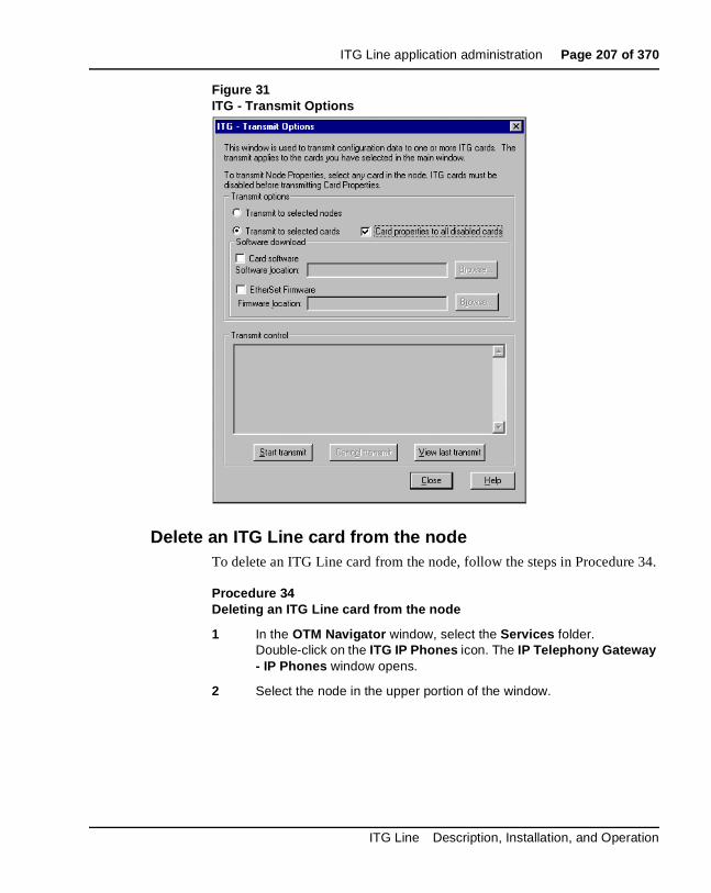
ITG Line application administration Page 207 of 370
Figure 31ITG - Transmit Options
Delete an ITG Line card from the nodeTo delete an ITG Line card from the node, follow the steps in Procedure 34.
Procedure 34Deleting an ITG Line card from the node
1 In the OTM Navigator window, select the Services folder. Double-click on the ITG IP Phones icon. The IP Telephony Gateway - IP Phones window opens.
2 Select the node in the upper portion of the window.
ITG Line Description, Installation, and Operation

Page 208 of 370 ITG Line application administration
3 If the ITG Line card to be deleted is a Leader 0, then:
• In the lower portion of the window, right-click on the card you want to delete. Select Telnet from the pop-up window. Log in to the card.
• Enter the clearLeader command from the ITGL> CLI. This removes the config.ini file from the card. It is a good practice to remove the config.ini file from the card in order to re-use that card in a different node at a later time.
4 In the IP Telephony Gateway - IP Phones window, select Node | Properties from the popup menu. The ITG Node Properties window is displayed.
5 Click the Configuration tab.
6 Select the ITG Line card to be deleted from the list.
7 Click the Delete button.
8 Click OK.
9 Next transmit the node properties. In the IP Telephony Gateway - IP Phones window, click the Configuration | Synchronize | Transmit. The ITG - Transmit Options window appears.
10 Select the Transmit to selected nodes radio button. Check the Node Properties to Active Leader check box.
11 Click the Start transmit button. Monitor progress in the Transmit Control window. Confirm that the node properties are transmitted successfully to Leader 0.
12 When the transmission is complete, click the Close button.
13 Remove the ITG Line card.
14 Remove the ITG Line card configuration data from the Call Server.
15 Identify the ITG Line card TN.
CAUTION WITH ESDS DEVICESFollow the anti-static procedures and place the ITG Line card in an appropriate anti-static package.
553-3001-204 Standard 3.00 March 2002
ITG Line application administration Page 209 of 370
16 In Overlay 20, enter the LTN (List Terminal Number) command where TYPE = tie, to list the TNs on the ITG Line card TN.
This returns a list of units equipped on the card. Verify the number of units that are equipped on the card. Note the first unit equipped on the card.
17 In Overlay 14, use the Out n command, where n equals the number of units that are equipped on the card.
18 At the TN prompt, enter the TN for the first unit that was equipped on the card. As the units are deleted, verify that you have “outed” the intended units.
—————————— End of Procedure ——————————
Change the IP addresses of an ITG Line node in OTMPrior to changing any IP address, ensure you understand the “IP Network Engineering Guidelines” on page 51, and consult with the IP network administrator. IP address configuration changes are completed on four tabs in the ITG Node Properties window. The four tabs are the:
• General tab – Configure network connections in this tab.See Figure 32 on page 218.
• Configuration tab – Card properties are set in this tab.See Figure 33 on page 218.
• SNMP Traps/Routing and IPs tab – SMNP traps and card routing table entries are configured in this tab.See Figure 35 on page 219.
• Ports tab – ELAN settings are set in this tab.See Figure 36 on page 220.
To change the IP address of an ITG Line node, follow the steps in Procedure 35 on page 210.
ITG Line Description, Installation, and Operation

Page 210 of 370 ITG Line application administration
Procedure 35Change the IP addresses of an ITG Line node in OTM
1 In the OTM Navigator window, select the Services folder. Double-click on the ITG IP Phones icon. The IP Telephony Gateway - IP Phones window appears.
2 Select the node in the upper portion of the window. Select the card in the lower portion of the window.
3 Click Configuration | Node | Properties to update the ITG Line card IP addresses as required.
4 Select the General tab (see Figure 32 on page 218).
Under Network Connections:
a. Never uncheck “Use separate subnets for voice and management”.
b. Voice LAN Node IP: This is also known as the TLAN IP address.
• if the node IP is changed, this will affect the configuration of the Connect Server IP address in the DHCP Server for the Internet Telephones
• if the Internet Telephones are using partial DHCP mode, manually reconfigure the IP address in each Internet Telephone
c. Management LAN gateway IP: This IP address is used to route to the ELAN. If OTM is not connected to the local ELAN then it communicates with this node through the Management LAN gateway. If you make changes to the gateway IP address and these changes are not coordinated properly, OTM will loose communication with the node:
• when a Management LAN gateway is added to the ELAN, it must restrict access so that only authorized traffic is permitted to come onto the ELAN
• the router must disable the BootP relay agent for ELAN interface
• the router must block all broadcast and multicast traffic from coming onto the ELAN and only allow proper access, that is, only authorized traffic and users coming through the Management LAN gateway. OTM is one of these users.
553-3001-204 Standard 3.00 March 2002

ITG Line application administration Page 211 of 370
d. Management LAN subnet mask: When changing these subnet masks, consider the possibility of conflict between the ELAN and TLAN IP addresses. Speak with the IP administrator before making any changes to subnets. Refer to “IP Network Engineering Guidelines” on page 51.
When changing the Management LAN (ELAN) subnet, this must be coordinated with the IP address on the Call Server (Active ELNK) subnet. You must also coordinate changes with the following:
• Management LAN gateway, and other IP devices on the ELAN (for example, OTM if it is local)
• any other devices on the ELAN and enterprise network (CLAN) that should need to communicate with ITG Line
• devices that are looking to receive SNMP traps
e. Voice LAN subnet mask: Coordinate with Voice LAN gateway (router). When changing the Voice LAN (TLAN) subnet mask, the change must be coordinated with changing the subnet mask of the Voice LAN (TLAN) gateway (router) interface.
Click Apply.
5 Select the Configuration tab (see Figure 33 on page 218).
Select the card to be changed from the list at the bottom of the tab.
Click the Host Names button. The Hostname Config window appears (see Figure 34 on page 219). The Hostname Config is part of the management information base. It allows the card to be identified by System Name, System Location, and System Contact to an SNMP management server. If you need to change any of these items, you must change them on each individual card. Click OK when done to return to the Configuration tab.
Under Card Properties:
a. Card Role: The first card in the node must exist. This card is Leader 0.
Every ITG Line node must have only one Leader 0. All other cards function as followers. OTM, however, requires that the first follower be configured as Leader 1 even though it has no leader functions. The remaining cards are configured as followers.
ITG Line Description, Installation, and Operation

Page 212 of 370 ITG Line application administration
b. Management IP: If you are changing the Management IP address of Leader 0, you must Telnet to the card and use the setLeader command to make the same change (new Management IP address) in the NVRAM of the Leader 0 card.
Leader 0 must be reset for OTM to resume communication with the node.
Note: Prior to resetting Leader 0, unplug all the other cards to prevent any other card from becoming the master. When Leader 0 restarts, plug the cards back in. These other cards with receive their new configuration for Leader 0.
c. Management MAC: All other IP configuration depends on the accurate configuration of the Management MAC address. The MAC address is located on the faceplate of the ITG Line card and is labelled as MOTHERBOARD Ethernet address. The Management MAC address is the same as the ELAN address.
d. Voice IP: This is the card voice IP address. This address is also known as the card TLAN IP address. In an ITG Line node, all cards must be assigned an address on the same TLAN subnet. The card voice IP address must be distinct from the node IP address.
e. Voice LAN gateway IP: This field is only enabled for the Leader 0 card and is disabled for all other cards. All cards in the ITG Line node must be on the TLAN, therefore they all share the same Voice LAN / TLAN gateway IP address.
553-3001-204 Standard 3.00 March 2002
ITG Line application administration Page 213 of 370
f. Card TN: It is mandatory that the Card TN format match both the machine type and the actual card slot where the card resides. Otherwise, the voice gateway channels will not function.
If you are trying to change the card TN format, first record the node configuration data. Delete the node. Change the card TN format to the correct machine, and rebuild the node.
For Option 51C/61C/81/81C systems, enter Card TN (l s c) information. For Option 11C, 11C-Mini, and Succession CSE 1000 systems, enter only the card slot number between 1-50. The card TN format is determined by the Meridian 1 and Succession CSE 1000 system type which is configured in the OTM navigator. You must enter the correct system type in the OTM Navigator before you add the node.
For each card:
• Click the Change button. The changes are reflected in the working list at the bottom of the tab.
• Click Apply to save the changes to the card in the database.
Select the next card to be changed from the working list at the bottom of the tab, make the appropriate changes, and then repeat the above two steps.
6 Select the SNMP Traps/Routing and IPs tab (see Figure 35 on page 219)
Changes can be made to the SNMP Traps and Card routing table entries without affecting other IP addresses. Change the SNMP traps and Card routing table entries as required, based on the destination host you are trying to reach.
IP addresses which are added here create special card routing tables that direct voice traffic out the ELAN and ELAN gateway. This can result in one-way transmission because the voice is streamed out the ELAN instead of the TLAN.
Under SNMP Traps:
a. Up to eight SNMP trap servers can be defined.
ITG Line Description, Installation, and Operation
Page 214 of 370 ITG Line application administration
Under Card routing table entries:
a. Use caution when assigning card routing table entries. Do not include the IP address of an Internet Telephone. Otherwise, voice traffic to these Internet Telephones will be incorrectly routed through the ELAN and ELAN gateway. To avoid including the wrong IP address it is recommended that you define Host IDs for the card routing table entries.
7 Select the Ports tab (see Figure 36 on page 220).
Under ELAN:
a. Meridian IP: A change to this IP address must be coordinated with the Call Server (Active ELNK) subnet.
b. Survival Cabinet IP: Declare each survival cabinet as if it were a separate subnet. For Option 11C, Option 11C-Mini, or Succession CSE 1000, this field is disabled unless you have defined at least one system as a survival cabinet of the main system in OTM Navigator.
Note: There is only one survival cabinet IP address for each node. Therefore, all ITG Line cards in the node must reside in the survival cabinet.
c. Signaling port: This field is read-only.
d. Broadcast port: This field is read-only.
Under TLAN:
a. Signaling port: This field is read-only.
b. Voices port: This field displays the range for RTP packets sent to the Internet Telephones. In general, keep the default value of 5200. If, however, there are numerous telephones working over low bandwidth WAN links using CISCO RTP header compression, then change the voice port to a number in the range of 16384 to 32767. Coordinate this value change with your IP network administrator.
Click Apply.
8 When all updates to the IP addresses have been made, click OK in the ITG Node Properties window.
553-3001-204 Standard 3.00 March 2002

ITG Line application administration Page 215 of 370
9 Unplug all the ITG Line cards, except Leader 0. Leader 0 gets its configuration from the BOOTP.TAB file. Plug in all the cards. Leader 0 forces its configuration to all the other cards.
10 You must now transmit the node or card properties to the Leader 0 card.
Select the Leader 0 ITG Line card in the IP Telephony Gateway - IP Phones window.
11 Click the Configuration | Synchronize | Transmit.
To transmit to the node, select the Transmit to selected nodes radio button. Check the Node Properties to Active Leader check box.
Click the Start transmit button.
The results of the transmit appear in the box under Transmit control. Verify that the properties transmitted successfully. If the transmit is unsuccessful, click the Start transmit button again.
If changes are made to the __________ tab...
... then you must transmit ___________ properties.
General
Note: If changes are made to the System Name, System Location, or System Contact in the Hostname Config window (Host Names button) you must transmit the card properties.
node
Configuration node
SNMP Traps/Routing and IPs card
Ports card
ITG Line Description, Installation, and Operation

Page 216 of 370 ITG Line application administration
12 To transmit the card properties, the cards must first be disabled. Login to Overlay 32 and disable the cards using the DISI command.
Click the Configuration | Synchronize | Transmit.
Select the Transmit to select cards radio button. Check the Card Properties to all disabled card check box.
Click the Start transmit button.
The results of the transmit appear in the box under Transmit control. Verify that the properties transmitted successfully. If the transmit is unsuccessful, click the Start transmit bottom again.
13 Click Close when the properties are successfully transmitted.
If you have changed the IP addresses of a single card, it must be restarted in order for the changes to take effect (see “Restarting an ITG Line card” on page 216). However, if you have changed IP addresses which affects the entire node, all cards in the node have to be restarted (see “Restarting all ITG Line cards” on page 217).
Restarting an ITG Line card
14 If the IP address of an ITG Line card has changed, restart that card only.
To prevent interruption to the speech path, login to Overlay 32. Type the DISI command. This command will disable the voice gateway channels when they become idle. DISI removes the call traffic but does not remove the Internet Telephones that are registered on that ITG Line card. The Graceful TPS Disable command will do this.
Type disiTPS at the card’s ITGL> prompt to disable the TPS service on the ITG Line card. This Graceful TPS Disable command prevents new Internet Telephones from registering on the card. All Internet Telephones registered on the card are redirected to another ITG Line card when the telephone becomes idle.
After the command is entered, an idle Internet Telephone is supposed to be updated with the Watchdog reset message. However, the TPS sends a soft reset message to the Internet Telephone, redirecting it to the Connect Server. The disabled TPS does not accept new registrations, so the Internet Telephones must register with another TPS in the node. Eventually, as all of the TPS’s Internet Telephones become idle, they are registered with other TPSs. The ITG Line card can then be removed with no impact to any users.
553-3001-204 Standard 3.00 March 2002

ITG Line application administration Page 217 of 370
Restarting all ITG Line cards
15 All cards have to be restarted if there has been a change to the following:
• node IP address
• subnet of either the TLAN or ELAN (by changing the subnet mask or the subnet fields of the IP address)
These changes affect the whole node and as a result all the cards have to be restarted.
If the Management IP address of Leader 0 has changed, all the cards have to be restarted. Even though this is a change to a single card, this change affects all cards, as OTM uses this address to transmit properties to the node:
a. Telnet to the card from OTM.
b. Use the setLeader command to set the new IP address. Leader 0 will use this new IP address when it reboots.
c. Reboot the Leader 0 using the cardReset command.
d. The Leader 0 card reads the new IP address from NVRAM.
e. Restart all the other cards.
—————————— End of Procedure ——————————
ITG Line Description, Installation, and Operation

Page 218 of 370 ITG Line application administration
Figure 32ITG Node Properties–General tab
Figure 33ITG Node Properties–Configuration tab
553-3001-204 Standard 3.00 March 2002

ITG Line application administration Page 219 of 370
Figure 34Hostname config
Figure 35ITG Node Properties–SNMP Traps/Routing and IPs tab
ITG Line Description, Installation, and Operation
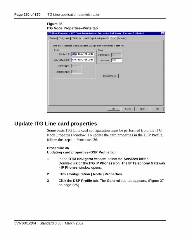
Page 220 of 370 ITG Line application administration
Figure 36ITG Node Properties–Ports tab
Update ITG Line card propertiesSome basic ITG Line card configuration must be performed from the ITG Node Properties window. To update the card properties in the DSP Profile, follow the steps in Procedure 36.
Procedure 36Updating card properties–DSP Profile tab
1 In the OTM Navigator window, select the Services folder. Double-click on the ITG IP Phones icon. The IP Telephony Gateway - IP Phones window opens.
2 Click Configuration | Node | Properties.
3 Click the DSP Profile tab. The General sub-tab appears. (Figure 37 on page 225)
553-3001-204 Standard 3.00 March 2002
ITG Line application administration Page 221 of 370
4 Under Diffserv Codepoint, modify the DSCP Control and Voice values only as directed by the IP network administrator. The Diffserv determines the priority of the packets in the IP network and can improve voice quality during times of network congestion. The values entered depend on the equipment in the data network. All ITG Line cards in the node should have the same DSP configuration.
The recommended configuration values are:
a. Control: A value of 40 - Class Selectore 5 (CS5)
b. Voice: A value of 46 Control DSCP - Expedited Forwarding (EF)
5 Under Loss and Level Plan, select your Country from the pull-down box.
6 Under Codec Options, leave the values at their default settings unless directed to change them to Nortel Networks Field Support.
a. Enable echo canceller: Leave checked.
b. Echo canceller tail: Select the maximum value.
c. Voice activity detection: The default value is –17. The range is –20 to +10 dB
d. Jitter buffer: The default is 50ms. The range is 0 ms to 200 ms and this is determined by the codec (see “Adjusting jitter buffer size” on page 87).
7 Click Apply.
8 Click the Codec Options sub-tab (Figure 38 on page 225).
Note: The Codec Options sub-tab contains a list of up to 32 codec settings for G.711, G.729A, and G.729AB for the ITG Line card.
9 Check only two codecs from the Codec # list.
The default Codec # settings are 4 and 17.
The Codec # indicates a particular codec (G.711 or G.729A) with different options for Frame Size and VAD (On or Off).
The lower of the two Codec #s that you check corresponds to BQ (Best Quality) and BB (Best Bandwidth) in Overlay 17.
For example, if you select Codec # 13 and Codec # 14:
• Codec # 13 corresponds with Best Quality
• Codec # 14 corresponds with Best Bandwidth
ITG Line Description, Installation, and Operation
Page 222 of 370 ITG Line application administration
10 Click Apply and then click OK.
—————————— End of Procedure ——————————
In order for changes to the DSP Profile tab to take effect, one of the following actions must be performed on the ITG Line card:
• Disable and re-enable the ITG Line card if the Codec Options have changed (see Procedure 37).
• Restart the ITG Line card if the DiffServ setting or Loss and Level Plan settings have changed (see Procedure 38).
If the Codec Option have changed on the DSP Profile tab, follow the steps in Procedure 37 to disable and re-enable the ITG Line card.
Procedure 37Disable and re-enable the ITG LIne card
1 Changes to the Codec Options (on either the General sub-tab or the Codec Options sub-tab) are applied immediately when the card properties are transmitted.
Login to Overlay 32 on the Call Server and use the DISI command to disable the ITG LIne card.
2 Open the OTM Navigator, click the Services folder. Double-click on ITG IP Phones icon. The IP Telephony Gateway - IP Phones window opens.
3 Select the ITG Line node from the list in the upper part of the main window. All ITG Line cards in the node are displayed in the lower part of the window. Select the node from the node list and press function key F5 or View | Refresh | Selection to refresh the card status of all cards in the selected node.
The card must be have a “Disabled” status before the card properties can be transmitted.
4 In the IP Telephony Gateway - IP Phones window, click the Configuration menu option and then select Synchronize | Transmit. The ITG - Transmit Options window appears.
5 Select the Transmit to selected cards radio button. Check the Card Properties to all disabled cards check box.
553-3001-204 Standard 3.00 March 2002

ITG Line application administration Page 223 of 370
6 Click the Start transmit button. Verify that the transmit is successfully under the Transmit Control and then click Close.
7 Login to the Call Server and go to Overlay 32. Type the ENCL command to enable the ITG Line card.
—————————— End of Procedure ——————————
If the DiffServ setting or Loss and Level Plan settings have changed, the ITG Line card must be restarted. To restart the ITG Line card, follow the steps in Procedure 38.
Procedure 38Restart the ITG Line card
1 The ITG Line card must be restarted for DiffServ Codepoint, and Loss and Level Plan changes to take effect.
To prevent a complete service interruption, it is recommended that changes to the DiffServ Codepoint take place on only a part of the node, and not to the entire node at once.
Each ITG Line card can support a maximum of 96 registered Internet Telephones on the TPS for signalling between the Internet Telephone and Call Server. There are two ways to determine the number of Internet Telephones registered on an ITG Line card:
a. The faceplate of the ITG Line card displays Lxxx, Fxxx, or Mxxx where xxx indicates the numbers of registered Internet Telephones.
b. Use the isetShow command.
If the average number of registered telephones on the ITG Line card is 45 or less, you can force the telephones to register (when idle) on the TPS of a different card by using the disiTPS command. This avoids disconnecting active calls by rebooting an ITG Line card that still has telephones registered on it.
2 Once you have checked the number of registered telephones on the card, check the available space on the other ITG Line cards in the node. The cards must be able to accommodate the Internet Telephones which will re-register to them.
3 Once you have determined there is available space, issue the DISI command in Overlay 32 to disable the cards.
ITG Line Description, Installation, and Operation

Page 224 of 370 ITG Line application administration
4 At the ITGL> prompt, enter the disiTPS command. This command disables the Internet Telephones when they are idle. The telephones can then re-register with the other ITG Line cards.
5 Monitor the progress of the disiTPS command by checking the number of telephones that are still registered on the card, using the isetShow command or watching the faceplate of the card. When the number of telephones registered on the card reaches zero, you can reboot the card without affecting any established calls
6 In the IP Telephony Gateway - IP Phones window, select the node in the top part of the window. Select the card you wish to restart in the lower part of the window. Double-click the card to open the ITG Card Properties window.
7 In the ITG Card Properties window, select the Maintenance tab. Click the Restart button.
8 Login to Overlay 32. Enter the ENCL command to enable the card.
9 Change the DiffServ Codepoint or Loss and Level Plan settings in the remaining cards in the node. Disable the remaining set of cards (using the DISI command). Issue the disiTPS command to have idle set re-register with other cards. Finally, reboot and re-enable these cards.
—————————— End of Procedure ——————————
553-3001-204 Standard 3.00 March 2002
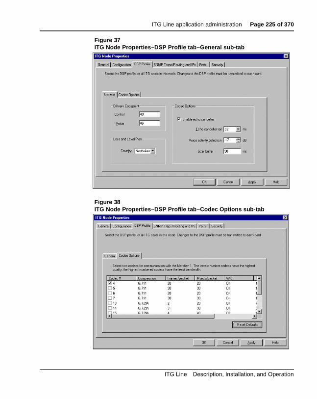
ITG Line application administration Page 225 of 370
Figure 37ITG Node Properties–DSP Profile tab–General sub-tab
Figure 38ITG Node Properties–DSP Profile tab–Codec Options sub-tab
ITG Line Description, Installation, and Operation
Page 226 of 370 ITG Line application administration
Use the Retrieve commandThe Retrieve command sends information from the ITG Line cards to the OTM ITG Line node. The Retrieve command is used for:
• downloading a node or card configuration by a remote OTM user
Note: This can also be performed by doing the “Add ITG Node” command and selecting the “Retrieve the active configuration from an existing node” option.
• copying node information from one node to another
• restoring accidentally changed OTM information, and
• downloading information to a fictitious “dummy” node that has been created for this purpose, in order to view the configuration of the ITG Line cards and node.
Procedure 39Using the Retrieve command
1 In the OTM Navigator window, select the Services folder. Double-click on the ITG IP Phones icon. The IP Telephony Gateway - IP Phones window opens.
2 Select the card(s) from which to retrieve information.
3 Click Configuration | Synchronize | Retrieve. The ITG - Retrieve Options window opens.
4 Under Retrieve Option, configure whether to retrieve Node properties or Card properties by clicking one or more of the check boxes.
5 Click Start Retrieve. The results of the Retrieve command are displayed under Retrieve control.
553-3001-204 Standard 3.00 March 2002

ITG Line application administration Page 227 of 370
Note 1: If the Retrieve command is successful, the current configuration of the node or card properties in OTM is overwritten by the configuration data that was retrieved from the node. The new configuration data can viewed in the ITG Node Properties window.
Note 2: If you want to view the configuration of a node without overwriting the current node configuration in OTM, retrieve the information to a dummy node.
—————————— End of Procedure ——————————
Figure 39ITG - Retrieve Options
ITG Line Description, Installation, and Operation

Page 228 of 370 ITG Line application administration
Add an ITG LIne node in OTM by retrieving an existing nodeUse this optional procedure in the following cases:
• Add existing nodes to a particular OTM PC to manage the ITG network from a single point of view.
• Restore the ITG configuration database to an OTM PC whose hard drive had crashed, as an alternative to restoring the OTM ITG Line nodes from the OTM Disaster Recovery Backup.
When you install and configure the ITG Line node manually, you can then add that node to another OTM PC by retrieving the configuration data from the existing ITG Line node.
Make sure that you configure the site name, system name, and customer number in the OTM Navigator before you add a new ITG Line node. Only one ITG Line node can be added in the OTM ITG application for each Meridian 1 and Succession CSE 1000 customer.
Note: If multiple OTM PCs are used to manage the same ITG network, care must be taken to synchronize the different copies of the ITG database. The OTM ITG Configuration | Synchronize | Retrieve function can be used to synchronize the OTM ITG database with the database on the ITG Line node.
Procedure 40Configuring the node and Leader 0
1 In the OTM Navigator window, select the Services folder, and then double-click on the ITG IP Phones icon. The IP Telephony Gateway - IP Phones window opens.
2 Click the Configuration | Node | Add. The Add ITG Node dialog box (see Figure 40 on page 230) appears.
3 Click the Retrieve the active configuration from an existing remote node radio button, and then click OK. The Retrieve ITG node window opens (see Figure 41 on page 231).
553-3001-204 Standard 3.00 March 2002

ITG Line application administration Page 229 of 370
4 The site name, Meridian 1 system name, and Meridian 1 customer number must exist in the OTM Navigator before you can add a new ITG Line node.
Note: Ensure the Meridian 1 system type is defined correctly. For example Option 81C, Option 11C, and Succession CSE 1000.
Under Node Location in the Retrieve ITG node window,
a. MAT site: Select the OTM Site.
b. MAT system: Select the Meridian 1 System.
c. Customer: Select the Meridian 1 Customer number.
d. Node Number: Ensure the node number is unique under the Meridian 1 customer number. Also, ensure that all ITG Line nodes connected to the same TLAN subnet have a unique node number regardless of the OTM site, Meridian 1 system, and customer number.
e. Active leader management IP: Enter the active leader management IP address field for the existing node.
f. SNMP community read/write name: Enter the SNMP read/write community name. The default is “private”.
5 Click Start retrieve.
The results of the retrieval are shown under Retrieve control. The node properties are retrieved from the active leader. The card properties are retrieved from Leader 0.
6 Click Close when the download is complete.
7 In the IP Telephony Gateway - IP Phones window, select the newly added node in the top part of the window.
8 Refresh the card status (View | Refresh) and verify that the cards in the newly added node are responding.
9 Select the Leader 0 card in the bottom of the window.
10 Click Configuration | Synchronize | Retrieve to retrieve the card properties for all ITG Line cards in the selected node. The ITG - Retrieve Options window opens (see Figure 42 on page 232).
11 Click the Card Properties check box and then click Start retrieve.
12 Verify the retrieve is successful under Retrieve control. Click Close.
ITG Line Description, Installation, and Operation

Page 230 of 370 ITG Line application administration
13 A new node has been created by retrieving data from another node Double-click on the new node in the IP Telephony Gateway - IP Phones window. The ITG Node Properties window will open for the newly added node.
14 Inspect each tab in the node properties and verify the data is correct and consistent with the node from which you retrieved. Click the Configuration tab, ensure the Host names information, IP addresses, and TN are consistent.
—————————— End of Procedure ——————————
Figure 40Add ITG Node dialog box
553-3001-204 Standard 3.00 March 2002

ITG Line application administration Page 231 of 370
Figure 41Retrieve ITG node
ITG Line Description, Installation, and Operation

Page 232 of 370 ITG Line application administration
Figure 42ITG - Retrieve Options
553-3001-204 Standard 3.00 March 2002

ITG Line application administration Page 233 of 370
ITG Line Command Line Interface access using Telnet or local RS-232 maintenance port
There are two ways to access the ITGL> Command Line Interface (CLI):
1 Use the NTAG81CA cable to connect the DIN8 pin connector on the faceplate, or the NTAG81BA cable to connect the DB9 I/O breakout cable to the COM port of a local PC. Use a null modem adapter to connect a modem for remote dial-up access.
2 Telnet to the card from the OTM IP Telephony Gateway - IP Phones window. This will automatically telnet to the IP address of the management interface (ELAN) of the card. You can also use the Telnet application on your computer and manually enter the management IP address (ELAN), voice IP address (TLAN), or the node IP address if you are trying to connect to the active leader.
Telnet to an ITG Line cardTo access the command line on an ITG Line card from the OTM PC, perform Procedure 41 on page 233.
Procedure 41Telnet to an ITG Line card
1 In the OTM Navigator window, select the Services folder. Double-click on the ITG IP Phones icon. The IP Telephony Gateway - IP Phones window opens.
2 Right-click on the ITG Line card that you wish to access. Select Card | Telnet to IP Telephony Gateway Line card from the popup menu. OTM PC opens a Telnet window and automatically connects to the ITG Line card by using the management IP address (ELAN).
3 Enter a username and password to access the ITGL> CLI. The default user name and password are both itgadmin. However, the user name and password should have been changed during installation.
CAUTIONDo not connect two maintenance terminals to both the faceplate and I/O panel serial maintenance port connections at the same time.
ITG Line Description, Installation, and Operation
Page 234 of 370 ITG Line application administration
4 The ITGL> prompt will appear if the login is successful. Type ? at the prompt to display a list of available ITGL> CLI commands. See “ITG Line CLI commands” on page 268 for a detailed list of commands.
—————————— End of Procedure ——————————
Reset the operational measurementsIf you suspect the Operational Measurements (OM) file may have collected some incorrect statistics, reset the OM file.
At the ITGL> prompt, type: resetOM.
The resetOM command resets all operational measurement parameters that have been collected since the last log dump. The statistics will start from zero.
Display the number of DSPsThe DSPNumShow command displays the number of DSPs on the ITG Line card.
At the ITGL> prompt, type: DSPNumShow.
Display ITG Line Node PropertiesThe IPInfoShow command displays information about an ITG Line node.
At the ITGL> prompt, type: IPInfoShow
The following ITG Line node information is displayed on the TTY:
• IP addresses for the management and voice subnets
• default router for the management and voice subnets
• subnet mask for the management and voice subnets
• SNMP manager
• IP routing table
• IP configuration of the card (which is related to the IP configuration of the node)
553-3001-204 Standard 3.00 March 2002

ITG Line application administration Page 235 of 370
The IPInfoShow command displays information similar to the following:
Maintenance Interface = lnIsa0 Maintenance IP address = 47.103.220.199 Maintenance subnet mask = 255.255.255.224 Voice Interface = lnPci1 Voice IP address = 47.103.247.221 Voice subnet mask = 255.255.255.0
ROUTE NET TABLE
ROUTE HOST TABLE
value = 77 = 0x4d = 'M'
Display ITG Line card propertiesThe itgCardShow command displays information about an ITG Line card. At the ITGL> prompt, type: itgCardShow
The itgCardShow commands display information similar to the following:
Index : 1Type : EXUTRole : LeaderNode : 123Leader IP : 47.103.247.220Card IP : 47.103.247.221Card TN : 44 0 10Card State : ENBLUptime : 1 days, 19 hours, 43 mins, 11 secs (157391 secs)Codecs : G711Ulaw(default), G711Alaw, G729ABlnPci stat : 100 Mbps (Carrier OK)value = 1 = 0x1
destination gateway flags Refcnt Use Interface
0.0.0.0 47.103.247.1 3 7 5800883
lnPci1
47.103.220.192
47.103.220.199 101 0 0 lnIsa0
47.103.247.0 47.103.247.221 101 0 0 lnPci1
47.103.247.0 47.103.247.221 101 0 0 lnPci1
destination gateway flags Refcnt Use Interface
127.0.0.1 127.0.0.1 5 0 0 lo0
ITG Line Description, Installation, and Operation
Page 236 of 370 ITG Line application administration
The following commands give additional information about an ITG Line card:
• ifShow
• serialNumShow
• firmwareVersionShow
• swVersionShow
Transfer files using the Command Line InterfaceThere are a number of special file transfer commands available to Put/Get files from the ITGL> CLI. These commands are normally used as part of an expert support procedures when OTM is not available to perform these tasks in the normal way.
These commands (see Table 31 on page 237) are from the perspective of the ITG Line card. If “Get” is part of the command, the file transfers from the OTM PC to the ITG Line card. If “Put” is part of the command the file transfers from the ITG Line card to the OTM PC.
To transfer a file enter one of the ITG line commands in Table 31 on page 237 at the ITGL> CLI depending on what type of file transfer is to occur.
553-3001-204 Standard 3.00 March 2002

ITG Line application administration Page 237 of 370
The following commands can be entered at the ITGL> CLI:
Note 1: These commands are case-sensitive. The parameters following the command must each be enclosed in quotes, and there must be a comma and no spaces between the parameters.
Note 2: For a complete description of the on these commands, seeTable 39 “File Transfer commands” on page 272.
Note 3: Hostname refers to either one of the following:• the IP address of the FTP host• the ITG Line card itself (use loopback address 127.0.0.1)• another ITG Line card
Table 31ITGL> CLI Commands–File Transfer
Command Parameters
swDownload <hostname> <username> <password> <directory path> <filename>
configFileGet <hostname> <username> <password> <directory path> <filename>
bootPFileGet <hostname> <username> <password> <directory path> <filename>
hostFileGet <hostname> <username> <password> <directory path> <filename> <ITGFileName> <listener>
bootPFilePut <hostname> <username> <password> <directory path> <filename>
currOMFilePut <hostname> <username> <password> <directory path> <filename>
prevOMFilePut <hostname> <username> <password> <directory path> <filename>
traceFilePut <hostname> <username> <password> <directory path> <filename>
logFilePut <hostname> <username> <password> <directory path> <filename>
configFilePut <hostname> <username> <password> <directory path> <filename>
hostFilePut <hostname> <username> <password> <directory path> <filename> <ITGFileName>
ITG Line Description, Installation, and Operation

Page 238 of 370 ITG Line application administration
IP configuration commandsTable 32 explains the IP configuration commands.
Configure TLAN parametersAuto-negotiate mode can be disabled if the ports on some data network hubs and routers are manually configured by the user. For example, configuring a port for 100BaseT Full Duplex can disable auto-negotiation on the signaling link.
The ITG Line card and the Internet Telephone default to Half Duplex mode when no auto-negotiation signaling occurs. The result is that the ITG Line card and the Internet Telephone operates in Half Duplex mode, while the hub is in Full Duplex mode. Communication continues, but random packet loss can occur which affects the correct operation and voice quality.
Note: Set ports for auto-negotiation, auto-sense.
Table 32IP configuration commands
IP configuration command
Function
setLeader Performs all the necessary actions to make a leader. Sets IP address, gateway, subnet mask, boot method to static, and leader bit in NVRAM.
clearLeader Clears the leader info in NVRAM and sets the boot method to use bootp, thus, making the card a follower:
NVRIPShow Prints the values of the IP parameters that reside in NVRAM.
553-3001-204 Standard 3.00 March 2002
ITG Line application administration Page 239 of 370
Configure the speed and duplex of the TLAN connection using the following commands:
• tLanSpeedSet speed–this command sets the speed of the TLAN interface. By default, the interface auto-negotiates to the highest speed supported by the hub or switch. If the switch is 10/100BaseT, the interface negotiates to 100BaseT. Use this command to debug Ethernet speed-related problems by forcing the interface to 10BaseT operation immediately. The duplex mode setting is saved in NVRAM and read at startup. The parameter speed is set to the following:
10 - disables auto-negotiation and sets speed to 10 mbs10100 - enables auto-negotiation
• tLanDuplexSet duplexMode–this command immediately sets the duplex mode of the TLAN interface while operating when Auto Negotiate is disabled and speed has been fixed to 10 mbs (or 10BaseT mode). The duplex mode is saved in NVRAM and read at startup. The parameter duplexMode is set to the following:
0 - enables Full Duplex mode1 - enables Half Duplex mode
It is recommended that you always use Half Duplex mode to inter-operate with the far end when the far end is set to Auto Negotiate.
If the duplex mode is set to Full Duplex you must guarantee the far end is set to Full Duplex and that Auto Negotiate is off.
Half Duplex mode works with either Half Duplex or Auto Negotiate at the far end. However, Full Duplex at the near the near end only operates with Full Duplex at the far end.
For the ITG Line application, Half Duplex has ample bandwidth for an ITG Line card even with 24 busy channels, VAD disabled, and G.711 codec with 10 mbs voice range.
ITG Line Description, Installation, and Operation
Page 240 of 370 ITG Line application administration
Packet loss monitorMonitor audio packet loss using the following commands:
• vgwPLLog 0|1|2–this command enables the packet loss monitor. A value of zero (0) disables packet loss logging. A value of one (1) logs a message if packet loss during the course of the call exceeds the threshold set with the itgPLThreshold command. Packet loss is measured in the receive direction and the two halves of a call are monitored and logged independently.
• itgPLThreshold xxx–this command sets the packet loss logging and alarm threshold, where xxx is a number between 1 and 1000, and represents the threshold in 0.1% increments. Packet loss which exceeds the threshold, generates an SNMP trap and writes a message to the log file if logging is enabled. The default value is 10 (1%).
Download the ITG Line error logThe ITG error log contains error conditions, as well as normal events. Some of the error conditions can be severe enough to raise an alarm through SNMP traps.
Use the LogFilePut command to download an ITG error log.
Lamp audit and keep-alive functionThe Meridian 1 and Succession CSE 1000 Lamp Audit function provides a continuous source of heartbeat messages to ensure the Internet Telephone is powered and the IP connection is alive. Since there is a reliable UDP connection from the Meridian 1 and Succession CSE 1000 core through to the Internet Telephone, any failure of the Internet Telephone, the ITG Line card, or the IP connection is detected.
553-3001-204 Standard 3.00 March 2002
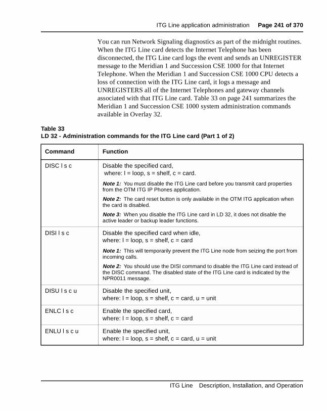
ITG Line application administration Page 241 of 370
You can run Network Signaling diagnostics as part of the midnight routines. When the ITG Line card detects the Internet Telephone has been disconnected, the ITG Line card logs the event and sends an UNREGISTER message to the Meridian 1 and Succession CSE 1000 for that Internet Telephone. When the Meridian 1 and Succession CSE 1000 CPU detects a loss of connection with the ITG Line card, it logs a message and UNREGISTERS all of the Internet Telephones and gateway channels associated with that ITG Line card. Table 33 on page 241 summarizes the Meridian 1 and Succession CSE 1000 system administration commands available in Overlay 32.
Table 33LD 32 - Administration commands for the ITG Line card (Part 1 of 2)
Command Function
DISC l s c Disable the specified card, where: l = loop, s = shelf, c = card.
Note 1: You must disable the ITG Line card before you transmit card properties from the OTM ITG IP Phones application.
Note 2: The card reset button is only available in the OTM ITG application when the card is disabled.
Note 3: When you disable the ITG Line card in LD 32, it does not disable the active leader or backup leader functions.
DISI l s c Disable the specified card when idle, where: l = loop, s = shelf, c = card
Note 1: This will temporarily prevent the ITG Line node from seizing the port from incoming calls.
Note 2: You should use the DISI command to disable the ITG Line card instead of the DISC command. The disabled state of the ITG Line card is indicated by the NPR0011 message.
DISU l s c u Disable the specified unit,where: l = loop, s = shelf, c = card, u = unit
ENLC l s c Enable the specified card,where: l = loop, s = shelf, c = card
ENLU l s c u Enable the specified unit,where: l = loop, s = shelf, c = card, u = unit
ITG Line Description, Installation, and Operation
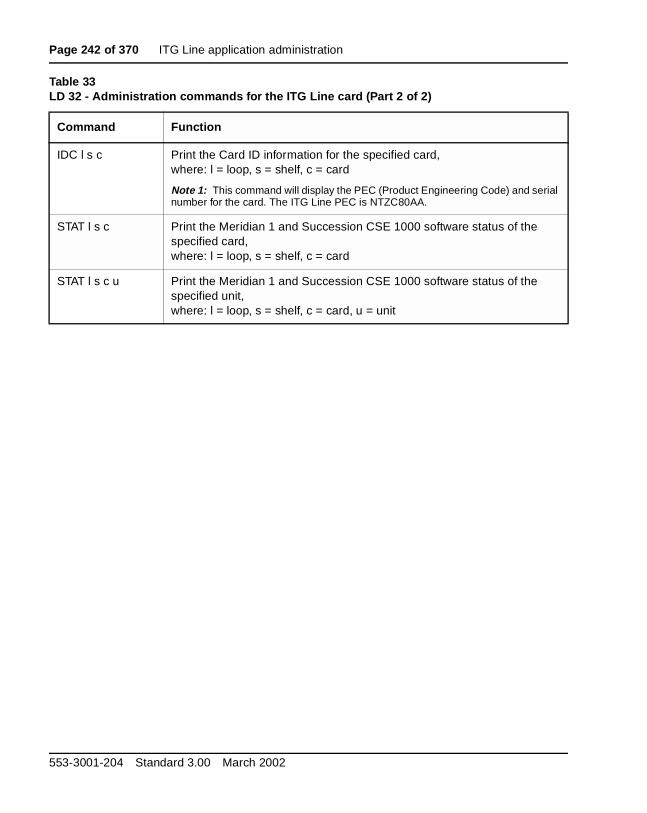
Page 242 of 370 ITG Line application administration
IDC l s c Print the Card ID information for the specified card,where: l = loop, s = shelf, c = card
Note 1: This command will display the PEC (Product Engineering Code) and serial number for the card. The ITG Line PEC is NTZC80AA.
STAT l s c Print the Meridian 1 and Succession CSE 1000 software status of the specified card,where: l = loop, s = shelf, c = card
STAT l s c u Print the Meridian 1 and Succession CSE 1000 software status of the specified unit, where: l = loop, s = shelf, c = card, u = unit
Table 33LD 32 - Administration commands for the ITG Line card (Part 2 of 2)
Command Function
553-3001-204 Standard 3.00 March 2002

Page 243 of 370
284
ITG Line card maintenanceContents
This section contains information on the following topics:
Overview . . . . . . . . . . . . . . . . . . . . . . . . . . . . . . . . . . . . . . . . . . . . . . . . 244
Faceplate maintenance display codes . . . . . . . . . . . . . . . . . . . . . . . . . . 244
System error messages . . . . . . . . . . . . . . . . . . . . . . . . . . . . . . . . . . . . . 247
Replacing an ITG Line card . . . . . . . . . . . . . . . . . . . . . . . . . . . . . . . . . 250
Verify ITG Line card software and firmware . . . . . . . . . . . . . . . . . . . . 253Transmitting card properties . .. . . . . . . . . . . . . . . . . . . . . . . . . . . . . 255
Access the ITGL> Command Line Interface from OTM . . . . . . . . . . . 257
Adding a “dummy” node for retrieving and viewing ITG Line node configuration . .. . . . . . . . . . . . . . . . . . . . . . . . . . . . . . . 258
Retrieving ITG configuration information from the ITG Line node . . . . . . . . . . . . . . . . . . . . . . . . . . . . . . . . . . . . . . . . . . . . . 263
ITG Line and Internet Telephone maintenance anddiagnostics - LD 32 . . . . . . . . . . . . . . . . . . . . . . . . . . . . . . . . . . . . . . . . 265
ITG Line CLI commands . . . . . . . . . . . . . . . . . . . . . . . . . . . . . . . . . . . 268
ITG Line card self-tests . . . . . . . . . . . . . . . . . . . . . . . . . . . . . . . . . . . . . 280
Troubleshooting a software load failure . . . . . . . . . . . . . . . . . . . . . . . . 280Warm rebooting the ITG Line card . . . . . . . . . . . . . . . . . . . . . . . . . 283Test the ITG Line card DSPs . . . . . . . . . . . . . . . . . . . . . . . . . . . . . . 283Work with alarm and log files . . . . . . . . . . . . . . . . . . . . . . . . . . . . . 283
Troubleshooting Internet Telephone Installation . . . . . . . . . . . . . . . . . 284
ITG Line Description, Installation, and Operation

Page 244 of 370 ITG Line card maintenance
OverviewThis chapter provides information on maintenance functions of the Meridian 1 and Succession Communication Server for Enterprise 1000 Internet Telephony Gateway (ITG) Line card. Where reference is made to Optivity Telephone Management (OTM), the latest version, OTM 1.2 (or later), is assumed.
Note: Check the Meridian 1 ESD web site for information on the latest software, firmware, and application releases. Refer to Procedure 17 on page 157 to for verification steps.
Faceplate maintenance display codesThe ITG Line card maintenance display provides the diagnostic status of the card during power-up, its operational state when in service, and error information on the functional state of the card. Table 34, “Faceplate maintenance display code,” on page 245 lists the normal and fault codes.
During power-up, the card performs multiple self-tests, including an internal RAM test, ALU test, address mode test, Boot ROM test, timer test, and external RAM test. If any of these tests fail, the card will enter a maintenance loop, and no further processing will be possible. A failure message is printed on the display to indicate which test failed. For example, if the timer test fails, F:05 is displayed.
If any of the other tests fail (up to and including the EEPROM test), a message is displayed for three seconds. If more than one test fails, the message displayed will indicate the first failure. If verbose mode has been selected (by the test input pin on the backplane), the three second failure message is not displayed.
553-3001-204 Standard 3.00 March 2002

ITG Line card maintenance Page 245 of 370
If the maintenance display shows a persistent T:20 indicating an ITG software failure and if this occurs after the card was reset during a software download procedure, call your Nortel Networks technical support for assistance in attempting to download new software onto the card.
Table 34Faceplate maintenance display code (Part 1 of 2)
Normal code Fault code Message
T:00 F:00 Initialization
T:01 F:01 Testing Internal RAM
T:02 F:02 Testing ALU
T:03 F:03 Testing address mode
T:04 F:04 Testing Boot ROM
T:05 F:05 Testing timers
T:06 F:06 Testing watchdog
T:07 F:07 Testing external RAM
T:08 F:08 Testing Host DPRAM
T:09 F:09 Testing DS30 DPRAM
T:10 F:10 Testing Security Device
T:11 F:11 Testing Flash memory
T:12 F:12 Programming PCI FPGA
T:13 F:13 Programming DS30 FPGA
T:14 F:14 Programming CEMUX FPGA
ITG Line Description, Installation, and Operation

Page 246 of 370 ITG Line card maintenance
T:15 F:15 Programming DSP FPGA
T:16 F:16 Testing CEMUX interface
T:17 F:17 Testing EEPROM
T:18 F:18 Booting processor, waiting for response with self-test information.
T:19 F:19 Waiting for application start-up messages from processor.
T:20 CardLAN enabled, transmitting BootP requests. If this display persists, then the ITG Line card is running in BIOS ROM mode due to card software failure.
T:21 CardLAN operational, A07 enabled, display now under host control.Card is looking for an active leader by sending BootP requests on the management LAN. If no BootP response is received on the management LAN, Leader 0 times out first and starts active leader tasks. A follower card sends BootP requests on the management LAN continuously and never times out. Enter “+++” to escape from BootP request mode and start ITG shell.
T:22 The ITG Line card is attempting to start the application.
Lxxx Card is running active leader tasks, where xxx = number of Internet Telephones registered on the card
Fxxx Card has detected the active leader, and is running Follower tasks, where xxx = number of Internet Telephones registered on the card.
Table 34Faceplate maintenance display code (Part 2 of 2)
553-3001-204 Standard 3.00 March 2002
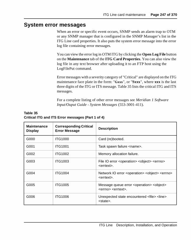
ITG Line card maintenance Page 247 of 370
System error messages When an error or specific event occurs, SNMP sends an alarm trap to OTM or any SNMP manager that is configured in the SNMP Manager’s list in the ITG Line card properties. It also puts the system error message into the error log file containing error messages.
You can view the error log in OTM ITG by clicking the Open Log File button on the Maintenance tab of the ITG Card Properties. You can also view the log file in any text browser after uploading it to an FTP host using the LogFilePut command.
Error messages with a severity category of "Critical" are displayed on the ITG maintenance face plate in the form: "Gxxx", or "Sxxx", where xxx is the last three digits of the ITG or ITS message. Table 35 lists the critical ITG and ITS messages.
For a complete listing of other error messages see Meridian 1 Software Input/Ouput Guide - System Messages (553-3001-411).
Table 35Critical ITG and ITS Error messages (Part 1 of 4)
Maintenance Display
Corresponding Critical Error Message
Description
G000 ITG1000 Card (re)booted.
G001 ITG1001 Task spawn failure <name>.
G002 ITG1002 Memory allocation failure.
G003 ITG1003 File IO error <operation> <object> <errno> <errtext>.
G004 ITG1004 Network IO error <operation> <object> <errno> <errtext>.
G005 ITG1005 Message queue error <operation> <object> <errno> <errtext>.
G006 ITG1006 Unexpected state encountered <file> <line> <state>.
ITG Line Description, Installation, and Operation
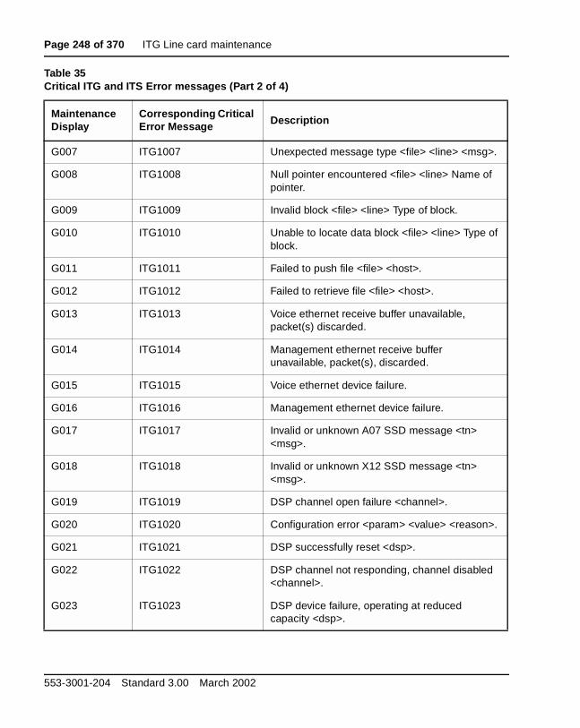
Page 248 of 370 ITG Line card maintenance
G007 ITG1007 Unexpected message type <file> <line> <msg>.
G008 ITG1008 Null pointer encountered <file> <line> Name of pointer.
G009 ITG1009 Invalid block <file> <line> Type of block.
G010 ITG1010 Unable to locate data block <file> <line> Type of block.
G011 ITG1011 Failed to push file <file> <host>.
G012 ITG1012 Failed to retrieve file <file> <host>.
G013 ITG1013 Voice ethernet receive buffer unavailable, packet(s) discarded.
G014 ITG1014 Management ethernet receive buffer unavailable, packet(s), discarded.
G015 ITG1015 Voice ethernet device failure.
G016 ITG1016 Management ethernet device failure.
G017 ITG1017 Invalid or unknown A07 SSD message <tn> <msg>.
G018 ITG1018 Invalid or unknown X12 SSD message <tn> <msg>.
G019 ITG1019 DSP channel open failure <channel>.
G020 ITG1020 Configuration error <param> <value> <reason>.
G021 ITG1021 DSP successfully reset <dsp>.
G022 ITG1022 DSP channel not responding, channel disabled <channel>.
G023 ITG1023 DSP device failure, operating at reduced capacity <dsp>.
Table 35Critical ITG and ITS Error messages (Part 2 of 4)
Maintenance Display
Corresponding Critical Error Message Description
553-3001-204 Standard 3.00 March 2002
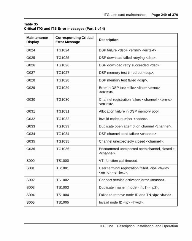
ITG Line card maintenance Page 249 of 370
G024 ITG1024 DSP failure <dsp> <errno> <errtext>.
G025 ITG1025 DSP download failed retrying <dsp>.
G026 ITG1026 DSP download retry succeeded <dsp>.
G027 ITG1027 DSP memory test timed out <dsp>.
G028 ITG1028 DSP memory test failed <dsp>.
G029 ITG1029 Error in DSP task <file> <line> <errno> <errtext>.
G030 ITG1030 Channel registration failure <channel> <errno> <errtext>.
G031 ITG1031 Allocation failure in DSP memory pool.
G032 ITG1032 Invalid codec number <codec>.
G033 ITG1033 Duplicate open attempt on channel <channel>.
G034 ITG1034 DSP channel send failure <channel>.
G035 ITG1035 Channel unexpectedly closed <channel>.
G036 ITG1036 Encountered unexpected open channel, closed it <channel>.
S000 ITS1000 VTI function call timeout.
S001 ITS1001 User terminal registration failed. <ip> <hwid> <errno> <errtext>.
S002 ITS1002 Connect service activation error <reason>.
S003 ITS1003 Duplicate master <node> <ip1> <ip2>.
S004 ITS1004 Failed to retrieve node ID and TN <ip> <hwid>
S005 ITS1005 Invalid node ID <ip> <hwid>.
Table 35Critical ITG and ITS Error messages (Part 3 of 4)
Maintenance Display
Corresponding Critical Error Message Description
ITG Line Description, Installation, and Operation
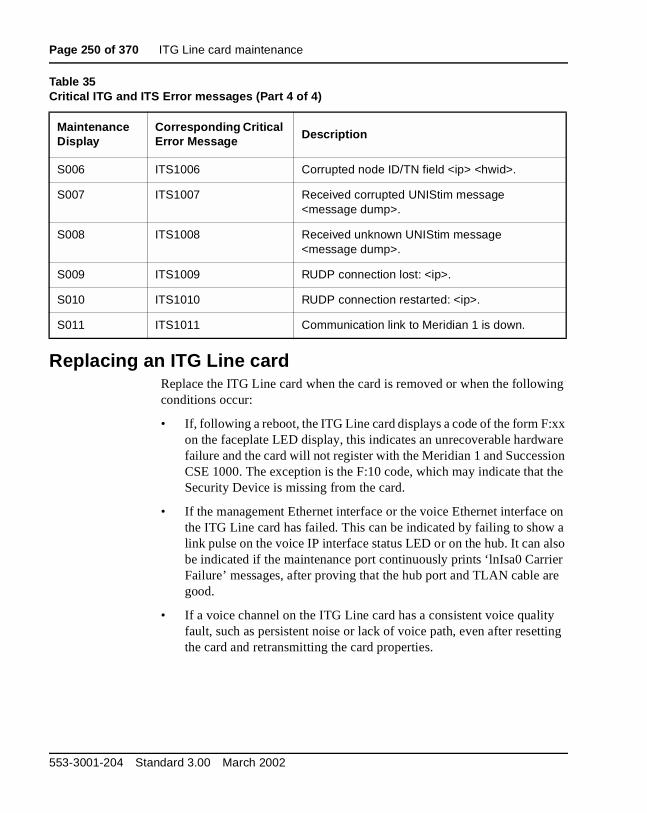
Page 250 of 370 ITG Line card maintenance
Replacing an ITG Line cardReplace the ITG Line card when the card is removed or when the following conditions occur:
• If, following a reboot, the ITG Line card displays a code of the form F:xx on the faceplate LED display, this indicates an unrecoverable hardware failure and the card will not register with the Meridian 1 and Succession CSE 1000. The exception is the F:10 code, which may indicate that the Security Device is missing from the card.
• If the management Ethernet interface or the voice Ethernet interface on the ITG Line card has failed. This can be indicated by failing to show a link pulse on the voice IP interface status LED or on the hub. It can also be indicated if the maintenance port continuously prints ‘lnIsa0 Carrier Failure’ messages, after proving that the hub port and TLAN cable are good.
• If a voice channel on the ITG Line card has a consistent voice quality fault, such as persistent noise or lack of voice path, even after resetting the card and retransmitting the card properties.
S006 ITS1006 Corrupted node ID/TN field <ip> <hwid>.
S007 ITS1007 Received corrupted UNIStim message <message dump>.
S008 ITS1008 Received unknown UNIStim message <message dump>.
S009 ITS1009 RUDP connection lost: <ip>.
S010 ITS1010 RUDP connection restarted: <ip>.
S011 ITS1011 Communication link to Meridian 1 is down.
Table 35Critical ITG and ITS Error messages (Part 4 of 4)
Maintenance Display
Corresponding Critical Error Message Description
553-3001-204 Standard 3.00 March 2002
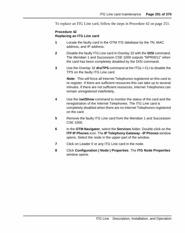
ITG Line card maintenance Page 251 of 370
To replace an ITG Line card, follow the steps in Procedure 42 on page 251.
Procedure 42Replacing an ITG Line card
1 Locate the faulty card in the OTM ITG database by the TN, MAC address, and IP address.
2 Disable the faulty ITG Line card in Overlay 32 with the DISI command. The Meridian 1 and Succession CSE 1000 outputs "NPR0011" when the card has been completely disabled by the DISI command.
3 Use the Overlay 32 disiTPS command at the ITGL> CLI to disable the TPS on the faulty ITG Line card.
Note: This will force all Internet Telephones registered on this card to re-register. If there are sufficient resources this can take up to several minutes. If there are not sufficient resources, Internet Telephones can remain unregistered indefinitely.
4 Use the isetShow command to monitor the status of the card and the reregistration of the Internet Telephones. The ITG Line card is completely disabled when there are no Internet Telephones registered on the card.
5 Remove the faulty ITG Line card from the Meridian 1 and Succession CSE 1000.
6 In the OTM Navigator, select the Services folder. Double-click on the ITP IP Phones icon. The IP Telephony Gateway - IP Phones window opens. Select the node in the upper part of the window.
7 Click on Leader 0 or any ITG Line card in the node.
8 Click Configuration | Node | Properties. The ITG Node Properties window opens.
ITG Line Description, Installation, and Operation

Page 252 of 370 ITG Line card maintenance
9 Click the Configuration tab.
a. Card role: Select the faulty ITG Line card from the list of cards in the node.
b. Management IP: This is the ELAN IP address for the card. OTM and Meridian 1 and Succession CSE 1000 uses this address to communicate with the card.
c. Management MAC: Change the “Management MAC” to the MAC address of the replacement ITG Line card. The MAC address is the Motherboard Ethernet address labeled on the faceplate of the replacement ITG Line card.
d. Voice IP: This is the TLAN IP address for the card.
e. Voice LAN gateway IP: This is the IP address of the router interface on the TLAN.
f. Card TN: For Option 51C/61C/81/81C, enter Card TN (l s c) information. For Option 11C and 11C-Mini, enter on the card number between 0-50.
10 Click Change, and then OK.
11 Select Leader 0 or any ITG Line card in the node in the IP Telephony Gateway - IP Phones window.
12 Use the Configuration | Synchronize | Transmit command to transmit the Node Properties from OTM to the active leader card (Leader 0) of the ITG Line node. The ITG - Transmit Options window opens.
13 Under Transmit options, select the Transmit to Selected Nodes radio button and check the Node Properties to Active Leader check box.
14 Click Start transmit. This will update the node properties on the active leader card with the MAC Address of the replacement ITG Line card. The results of the transmit will display under Transmit control. When the transmit is successful, click Close.
15 Install the replacement ITG Line card into the card slots in the Meridian 1 and Succession CSE 1000 IPE module or Option 11 cabinet. To do this:
a. Pull the top and bottom locking devices away from the ITG faceplate.
553-3001-204 Standard 3.00 March 2002

ITG Line card maintenance Page 253 of 370
b. Insert the ITG Line card into the card guides and gently push it until it makes contact with the backplane connector. Hook the locking devices.
Note 1: When ITG Line cards are installed, the red LED on the faceplate remains lit until the card is configured and enabled in software, at which point in turns off. If the LED does not follow the pattern described or operates in any other manner (such as continually flashing or remaining weakly lit), replace the card.
Note 2: Observe the ITG faceplate maintenance display to see startup self-test results and status messages. A display of the type F:xx indicates a failure. Refer to Table 34 on page 245 for a listing of display codes.
16 In the OTM IP Telephony Gateway- IP Phones window, select View | Refresh and verify that the replacement ITG Line card status is showing “Unequipped.”
—————————— End of Procedure ——————————
Verify ITG Line card software and firmwareTo verify the software on the ITG Line card and the firmware on the i2004 Internet Telephone, follow the steps in Procedure 43.
Procedure 43Verifying ITG Line card software and firmware
Note: Refer also to Procedure 17, “Verify card software and i2004 Internet Telephone firmware” on page 157.
1 Check the Nortel Networks Customer Support web site for the latest software and firmware releases:
a. Connect to the following URL using any PC with Internet access: http://www.nortelnetworks.com
b. Point at the Customer Support link from the menu on the left of the screen. Click on Software Distribution from the pop-up menu. The Software Downloads page will appear.
c. On the Software Downloads page, under the blue Product Selection bar on the right, click the View by a Product link. The Product Select page will open.
ITG Line Description, Installation, and Operation
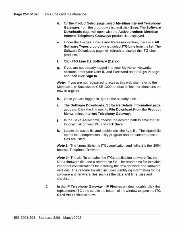
Page 254 of 370 ITG Line card maintenance
d. On the Product Select page, select Meridian Internet Telephony Gateways from the drop-down list, and click Save. The Software Downloads page will open with the Active product: Meridian Internet Telephony Gateways product list displayed.
e. Under the Images, Loads and Releases section, there is a All Software Types drop-down list, select ITG Line from the list. The Software Downloads page will refresh to display the ITG Line products.
f. Click ITG Line 2.2 Software (2.2.xx).
g. If you are not already logged into your My Nortel Networks account, enter your User ID and Password on the Sign In page and then click Sign In.
Note: If you are not registered to access this web site, refer to the Meridian 1 or Succession CSE 1000 product bulletin for directions on how to register.
h. Once you are logged in, ignore the security alert.
i. The Software Downloads: Software Details Information page appears. Click the link next to File Download.From the Product Menu, select Internet Telephony Gateway.
j. In the Save As window, choose the desired path to save the file to local disk on your PC and click Save.
k. Locate the saved file and double-click the *.zip file. The zipped file opens in a compression utility program and the uncompressed files are listed.
Note 1: The *.mms file is the ITGL application and fwfile.1 is the i2004 Internet Telephone firmware.
Note 2: The zip file contains the ITGL application software file, the i2004 firmware file, and a readme.txt file. The readme.txt file explains important considerations for installing the new software and firmware versions. The readme file also includes identifying information for the software and firmware files such as the date and time, size and checksum.
2 In the IP Telephony Gateway - IP Phones window, double-click the replacement ITG Line card in the bottom of the window to open the ITG Card Properties window.
553-3001-204 Standard 3.00 March 2002
ITG Line card maintenance Page 255 of 370
3 Leave the defaults in the Maintenance tab of the ITG Card Properties window. Click the Configuration tab.
4 Verify that the S/W version shows the latest recommended ITG Line card software version. Verify that the IP Phone F/w version is the latest recommended release of the i2004 Internet Telephone firmware. Click OK.
5 Upgrade the software and/or firmware if required. Refer to “Upgrade ITG Line card software from the web” on page 160 and “Upgrade i2004 Internet Telephone firmware” on page 162.
—————————— End of Procedure ——————————
Transmitting card propertiesTo transmit cards properties to the ITG Line cards, follow the steps in Procedure 44.
Procedure 44Transmitting Card Properties
1 In the OTM Navigator, select the Services folder. Double-click on the ITP IP Phones icon. The IP Telephony Gateway - IP Phones window opens.
2 Select the replacement ITG Line card.
3 Click Configuration | Synchronize | Transmit.
4 The ITG - Transmit Options window opens (Figure 43 on page 256).
5 Select the Transmit to selected cards radio button. Check the Card properties to all disable card check box.
6 Click the Start transmit button.
The transmission status is displayed under Transmit control. Confirm that Card Properties are transmitted successfully.
7 When the transmission is successful, click Close.
8 Use the Overlay 32 ENLC command at the ITGL> prompt, to re-enable the ITG Line card.
9 Verify that the card is enabled in the IP Telephony Gateway - IP Phones. Locate the card in the list at the bottom of the screen. Look under the Card state column and verify the card is Enabled.
ITG Line Description, Installation, and Operation

Page 256 of 370 ITG Line card maintenance
10 Update the Installation Summary Sheet with the new MAC address (see “ITG Line card installation summary sheet” on page 100).
11 Verify the TN, management interface MAC address, and IP address for each ITG Line card. Compare the displayed values with those on the ITG Installation Summary Sheet.
—————————— End of Procedure ——————————
Figure 43ITG Transmit Options dialog box
553-3001-204 Standard 3.00 March 2002
ITG Line card maintenance Page 257 of 370
Access the ITGL> Command Line Interface from OTMTo access the ITGL> CLI from with OTM, follow the steps in Procedure 45.
Procedure 45Telnet to an ITG Line card
1 In the OTM Navigator, select the Services folder. Double-click on the ITP IP Phones icon. The IP Telephony Gateway - IP Phones window opens.
2 Right-click the ITG Line card that you wish to access, and select Card | Telnet to IP Telephony Gateway Line 2.0 card from the popup menu.
3 Enter the current user name and password. If the user name and password have not been changed, use the default user name and password is itgadmin and itgadmin.
Note: This user name and password must be changed. Never leave the default user name and password for a system that is in service (see “Changing the ITGL> CLI shell user name and password” on page 174).
The OTM PC opens a Telnet window and automatically connects to the ITG Line card by using the management IP address. After entering a username and password, the ITGL> CLI is accessed from the OTM PC.
—————————— End of Procedure ——————————
ITG Line Description, Installation, and Operation
Page 258 of 370 ITG Line card maintenance
Adding a “dummy” node for retrieving and viewing ITG Line node configuration
Use this procedure to create a “dummy” ITG Line node for retrieving and viewing the actual ITG Line node configuration, without over-writing the existing ITG configuration data for an existing node in the OTM ITG database.
Retrieving the actual ITG Line node configuration to the “dummy” node is useful in the following cases:
• to isolate ITG Line node configuration faults
• to determine which copy of the database is correct, in order to determine the desired direction of database synchronization:
— transmit OTM ITG to ITG Line node, or
— retrieve ITG Line node to OTM ITG Line node.
The dummy node can be added manually or by retrieving the ITG Line node configuration data from an existing node.
The site name, Meridian 1 and Succession CSE 1000 system name, and Meridian 1 and Succession CSE 1000 customer number must exist in the OTM Navigator before you can add a new ITG Line node.
Procedure 46 is the recommended method to create the "dummy" ITG Line node.
Procedure 46Creating the “dummy” ITG Line node to retrieve actual configuration
1 In OTM Navigator, click Configuration | Add Site (see Figure 44 on page 260). The New Site Properties window opens.
2 In the New Site Properties window (see Figure 45 on page 261), set the following:
a. Site Name: Add a site named “Retrieve ITG data.”
b. Short Name: Enter a short name for the site.
553-3001-204 Standard 3.00 March 2002

ITG Line card maintenance Page 259 of 370
Under Site Location:
a. Add the Address, City, State/Province, Country, and Zip/Postal Code of the site.
Under Contact Information:
a. Add the Name, Phone Number, Job Title, and any Comments for the site contact person(s).
3 Click Apply, and then OK.
4 In OTM Navigator, click Configuration | Add System. The Add System window opens.
5 Add a system named “Dummy,” of type “Meridian 1,” under the site named “Retrieve ITG data.”
Under System Type, click Meridian 1, and then click OK. The <Your Site> - System Properties window opens (see Figure 46 on page 262).
6 Click the Customers tab (see Figure 47 on page 263).
Click Add. Add Customer Number “99” on the “dummy” Meridian 1 and Succession CSE 1000 system.
7 To view the actual data, select the “dummy” node and change the management IP address in the node properties to access the desired node.
8 Use the Configuration | Synchronize | Retrieve function to retrieve data from that node.
9 Confirm to over-write the OTM ITG data for the “dummy” node.
—————————— End of Procedure ——————————
ITG Line Description, Installation, and Operation
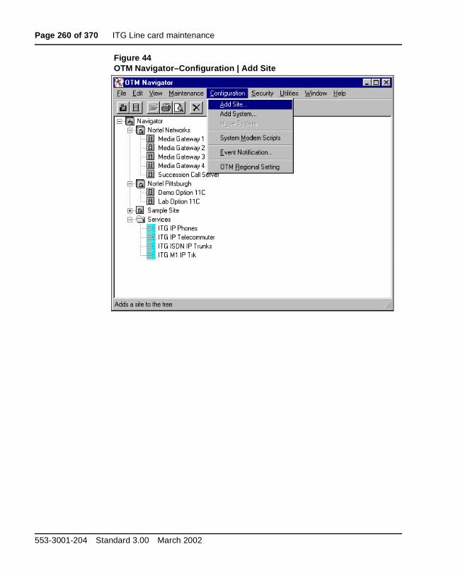
Page 260 of 370 ITG Line card maintenance
Figure 44OTM Navigator–Configuration | Add Site
553-3001-204 Standard 3.00 March 2002

ITG Line card maintenance Page 261 of 370
Figure 45New Site Properties
ITG Line Description, Installation, and Operation

Page 262 of 370 ITG Line card maintenance
Figure 46System Properties–General Tab
553-3001-204 Standard 3.00 March 2002
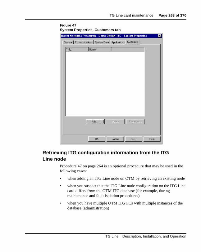
ITG Line card maintenance Page 263 of 370
Figure 47System Properties–Customers tab
Retrieving ITG configuration information from the ITG Line node
Procedure 47 on page 264 is an optional procedure that may be used in the following cases:
• when adding an ITG Line node on OTM by retrieving an existing node
• when you suspect that the ITG Line node configuration on the ITG Line card differs from the OTM ITG database (for example, during maintenance and fault isolation procedures)
• when you have multiple OTM ITG PCs with multiple instances of the database (administration)
ITG Line Description, Installation, and Operation
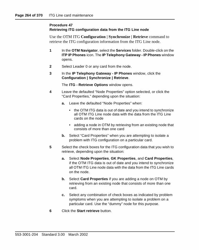
Page 264 of 370 ITG Line card maintenance
Procedure 47Retrieving ITG configuration data from the ITG Line node
Use the OTM ITG Configuration | Synchronize | Retrieve command to retrieve the ITG configuration information from the ITG Line node.
1 In the OTM Navigator, select the Services folder. Double-click on the ITP IP Phones icon. The IP Telephony Gateway - IP Phones window opens.
2 Select Leader 0 or any card from the node.
3 In the IP Telephony Gateway - IP Phones window, click the Configuration | Synchronize | Retrieve.
The ITG - Retrieve Options window opens.
4 Leave the defaulted “Node Properties” option selected, or click the “Card Properties,” depending upon the situation:
a. Leave the defaulted “Node Properties” when:
• the OTM ITG data is out of date and you intend to synchronize all OTM ITG Line node data with the data from the ITG Line cards on the node
• adding a node in OTM by retrieving from an existing node that consists of more than one card
b. Select “Card Properties” when you are attempting to isolate a problem with ITG configuration on a particular card.
5 Select the check boxes for the ITG configuration data that you wish to retrieve, depending upon the situation:
a. Select Node Properties, GK Properties, and Card Properties, if the OTM ITG data is out of date and you intend to synchronize all OTM ITG Line node data with the data from the ITG Line cards on the node.
b. Select Card Properties if you are adding a node on OTM by retrieving from an existing node that consists of more than one card.
c. Select any combination of check boxes as indicated by problem symptoms when you are attempting to isolate a problem on a particular card. Use the “dummy” node for this purpose.
6 Click the Start retrieve button.
553-3001-204 Standard 3.00 March 2002
ITG Line card maintenance Page 265 of 370
7 Monitor the progress of the retrieval under Retrieve control box.
The retrieved Node Properties, GK Properties, and Card Properties, will overwrite the existing OTM ITG configuration data for the respective node or card.
The “Retrieving the ITG configuration information from the ITG Line node” procedure is complete.
—————————— End of Procedure ——————————
ITG Line and Internet Telephone maintenance anddiagnostics - LD 32
For Nortel Networks Internet Telephones, there are two kinds of TNs to consider:
• Physical TN, which represents a physical unit of the ITG Line card
• Virtual TN, which is configured on a virtual superloop and represents an Internet Telephone
Physical TNs, that are seen as trunk units, are managed using existing LD 32 commands.
Because virtual TNs are configured on a virtual superloop, Virtual TN maintenance has no meaning. That is, what is already provided by the Meridian 1 and Succession CSE 1000 for phantom loops. In Overlay 32, any command affecting a phantom loop leads to an NTP665 message, since the loop does not physically exist. Overlay 32 supports STAT, DISU, ENLU, and IDU commands on an Internet Telephone Virtual TN. All other commands lead to the new NPR047 message.
The IDU command provides information such as
• TN
• TNID
• NT code
• color code
• release code
ITG Line Description, Installation, and Operation

Page 266 of 370 ITG Line card maintenance
• serial number
• IP address of the
• IP address of the ITG Line card that is acting as the terminal proxy
The serial number is the last three bytes of the Internet Telephone’s MAC address, printed in ASCII hexadecimal format.
Since the Meridian 1 and Succession CSE 1000 must request the information from the Internet Telephone, the IDU is effectively a PING command and can be used to test the end-to-end IP connectivity of the Internet Telephone. The output format of the IDU command in LD 32 is shown in Table 36. This format only applies for Internet Telephone Virtual TNs. Table 37 contains the maintenance commands in LD 32 for the Internet Telephone.
If the Internet Telephone is not registered with the Meridian 1 and Succession CSE 1000, an NPR0048 message is generated. If the Internet Telephone is registered but idle, the system prints the Internet Telephone IP address and ITG Line card IP address and generates an NPR0053 message.
Table 36IDU command printout in LD 32
Item Description
ISET TN: l s c u
TN ID CODE: I2004 or i2050
NT CODE: xxxxxx
COLOR CODE: xx
RLS CODE: xx
SER NUM: xxxxxxx
SET IP ADR: xxx.xxx.xxx.xxx
TPS IP ADR: xxx.xxx.xxx.xxx
553-3001-204 Standard 3.00 March 2002
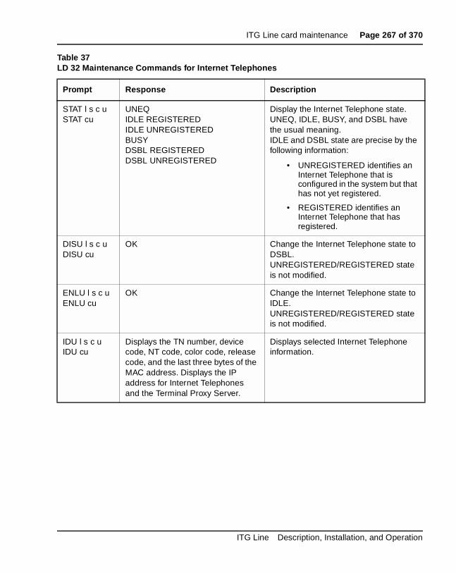
ITG Line card maintenance Page 267 of 370
Table 37LD 32 Maintenance Commands for Internet Telephones
Prompt Response Description
STAT l s c uSTAT cu
UNEQIDLE REGISTEREDIDLE UNREGISTEREDBUSYDSBL REGISTEREDDSBL UNREGISTERED
Display the Internet Telephone state.UNEQ, IDLE, BUSY, and DSBL have the usual meaning. IDLE and DSBL state are precise by the following information:
• UNREGISTERED identifies an Internet Telephone that is configured in the system but that has not yet registered.
• REGISTERED identifies an Internet Telephone that has registered.
DISU l s c uDISU cu
OK Change the Internet Telephone state to DSBL.UNREGISTERED/REGISTERED state is not modified.
ENLU l s c uENLU cu
OK Change the Internet Telephone state to IDLE. UNREGISTERED/REGISTERED state is not modified.
IDU l s c uIDU cu
Displays the TN number, device code, NT code, color code, release code, and the last three bytes of the MAC address. Displays the IP address for Internet Telephones and the Terminal Proxy Server.
Displays selected Internet Telephone information.
ITG Line Description, Installation, and Operation

Page 268 of 370 ITG Line card maintenance
ITG Line CLI commandsITG Line CLI commands are designed to supplement overlay commands, and to introduce new features specific to the ITG platform.
The ITG Line CLI commands are accessed by connecting a TTY to the MAINT port on the ITG Line card faceplate. Alternatively, the OTM ITG Telnet command can be used to access the ITG Command Line Interface. These ITG Line CLI commands are entered at the ITGL> prompt.
The commands are grouped into the following categories:
• “General Purpose commands” on page 269
• “File Transfer commands” on page 272
• “IP Configuration commands” on page 275
• “Reset commands” on page 276
• “DSP commands” on page 276
• “Upgrade commands” on page 277
• “ITGL> Shell command” on page 277
• “Internet Telephone Installer Password commands” on page 278
• “VGW commands” on page 280
553-3001-204 Standard 3.00 March 2002

ITG Line card maintenance Page 269 of 370
Table 38 lists the general purpose ITGL> commands applicable to the ITG Line card.
Table 38General Purpose commands (Part 1 of 3)
ITGL> Command Description
i Display the current task list.
itgHelp Displays the complete command list. ? will also show the command list.
logout Exits the ITGL> command line interface.
routeAdd Add a route to the network routing table.
routeShow Displays the current host and network routing tables.
logPrintOff Turns off logging in the TTY session where you are currently logged in.
logPrintOn Turns off logging in the TTY session where you are currently logged in.
chkdsk chkdsk “/C:”Checks the internal file system for errors.chkdsk “/C:”, 1Repairs the file system errors and saves the damaged cluster in files.chkdsk “/C:”, 2 Repairs file system errors and returns damaged clusters to the free pool.
ping "host", "numpackets"
This command sends an ICMP ECHO_REQUEST packet to a network host. The host matching the destination address in the packets will respond to the request. If a response is not returned, the sender will time out. This command is useful to determine if other hosts or ITG Line cards are communicating with the sender card. The "numpackets" parameter specifies how many packets to send. If it is not included, ping runs until it is stopped by Ctrl-C (which also exits the ITGL command line interface).Example: ITGL> ping "47.82.33.123", 10
itgCardShow Displays ITG Line card information.
itgMemShow Displays memory usage.
ITG Line Description, Installation, and Operation
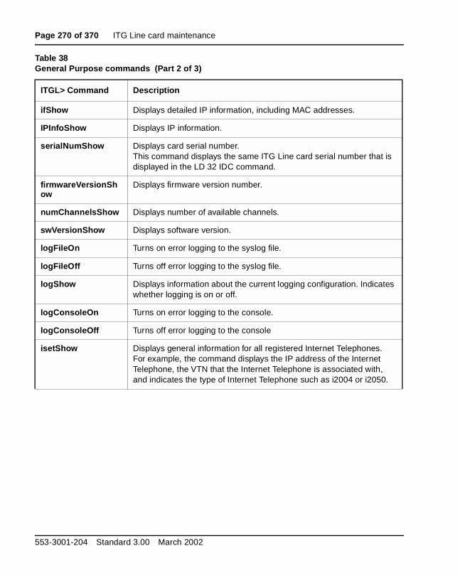
Page 270 of 370 ITG Line card maintenance
ifShow Displays detailed IP information, including MAC addresses.
IPInfoShow Displays IP information.
serialNumShow Displays card serial number.This command displays the same ITG Line card serial number that is displayed in the LD 32 IDC command.
firmwareVersionShow
Displays firmware version number.
numChannelsShow Displays number of available channels.
swVersionShow Displays software version.
logFileOn Turns on error logging to the syslog file.
logFileOff Turns off error logging to the syslog file.
logShow Displays information about the current logging configuration. Indicates whether logging is on or off.
logConsoleOn Turns on error logging to the console.
logConsoleOff Turns off error logging to the console
isetShow Displays general information for all registered Internet Telephones. For example, the command displays the IP address of the Internet Telephone, the VTN that the Internet Telephone is associated with, and indicates the type of Internet Telephone such as i2004 or i2050.
Table 38General Purpose commands (Part 2 of 3)
ITGL> Command Description
553-3001-204 Standard 3.00 March 2002
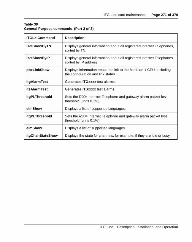
ITG Line card maintenance Page 271 of 370
isetShowByTN Displays general information about all registered Internet Telephones, sorted by TN.
isetShowByIP Displays general information about all registered Internet Telephones, sorted by IP address.
pbxLinkShow Displays information about the link to the Meridian 1 CPU, including the configuration and link status.
itgAlarmTest Generates ITGxxxx test alarms.
itsAlarmTest Generates ITSxxxx test alarms.
itgPLThreshold Sets the i2004 Internet Telephone and gateway alarm packet loss threshold (units 0.1%).
elmShow Displays a list of supported languages.
itgPLThreshold Sets the i2004 Internet Telephone and gateway alarm packet loss threshold (units 0.1%).
elmShow Displays a list of supported languages.
itgChanStateShow Displays the state for channels, for example, if they are idle or busy.
Table 38General Purpose commands (Part 3 of 3)
ITGL> Command Description
ITG Line Description, Installation, and Operation

Page 272 of 370 ITG Line card maintenance
Table 39 lists the file transfer commands used with the ITG Line card.
Table 39File Transfer commands (Part 1 of 3)
ITGL> Commands Description
swDownload "hostname", "username", "password", "directory path", "filename"
Loads a new version of software from the FTP host to the ITG Line card.Updates the software on the ITG Line card with the binary file received from an FTP server corresponding to the hostname IP address. The ITG Line card FTP client performs a get which downloads the file to the ITG flash bank. A checksum is calculated to verify correct delivery. Once the new software version is successfully downloaded, the ITG Line card must be rebooted with cardReset in order to run the new software.
Note: Hostname refers to the either IP address of the FTP host, or the ITG Line card itself or another ITG Line card when a PC card in the A: drive of the ITG Line card contains the software binary file.
Example:ITGL> swDownload "47.82.32.346", "anonymous", "guest", "/software", "vxWorks.mms"
configFileGet "hostname", "username", "password", "directory path", "filename"
Sends an updated config.ini file from OTM to the ITG Line card.Updates the config.ini file on the ITG Line card with the config.ini file on the specified host, account, and path. The configFileGet task on the ITG host initiates an FTP session with the given parameters and downloads the file to flash file system. The config.ini file also contains the gatekeeper IP address, gateway password, and gateway DN-port mapping table.Example:ITGL> configFileGet "ngals042", "anonymous", "guest", "/configDir", "config.ini"
bootPFileGet "hostname", "username", "password", "directory path", "filename"
Updates the bootptab file on the ITG Line card with the bootptab file on the specified host, account and path. The bootpFileGet task on the ITG host initiates an FTP session with the given parameters and downloads the file to flash file system.Example:ITGL> bootPFileGet "ngals042", "anonymous", "guest", "/bootpDir", "bootptab"
553-3001-204 Standard 3.00 March 2002

ITG Line card maintenance Page 273 of 370
hostFileGet "hostname", "username", "password", "directory path", "filename", "ITGFileName", listener
Transfers any file from OTM to the ITG Line card. This command gets any file from the host and does a Get using FTP to the ITG Line card.
Note: ITGFileName is the full path AND filename of where the file is to be placed. The listener parameter indicates which module to inform of the successful file transfer. It can be set to –1 to be disabled.
Example:ITGL> hostFileGet "ngals042", "anonymous", "guest", "/hostfileDir", "hostFile.txt", "/C:ITGFILRDIR/ITGFILE.TXT", -1
currOMFilePut "hostname", "username", "password", "directory path", "filename"
Sends the current operational measurements (OM) file to the specified host.The OMFilePut task on the ITG host initiates an FTP session with the given parameters and downloads the ITG Line card’s operational measurements file to the specified location on the host.Example:ITGL> currOMFilePut "ngals042", "anonymous", "guest", "/currDir", "omFile"
prevOMFilePut "hostname", "username", "password", "directory path", "filename"
Sends the previous operational measurements (OM) file to the specified host.The OMFilePut task on the ITG host initiates an FTP session with the given parameters and downloads the ITG Line card’s operational measurements file to the specified location on the host.Example:ITGL> prevOMFilePut "ngals042", "anonymous", "guest", "/prevDir", "omFile"
traceFilePut "hostname", "username", "password", "directory path", "filename"
Send the syslog file to the specified host.The traceFilePut task on the ITG host initiates an FTP session with the given parameters and downloads the ITG Line card’s call trace file to the specified location on the host.Example:ITGL> traceFilePut "ngals042", "anonymous", "guest", "/trcDir", "trcFile"
Table 39File Transfer commands (Part 2 of 3)
ITGL> Commands Description
ITG Line Description, Installation, and Operation
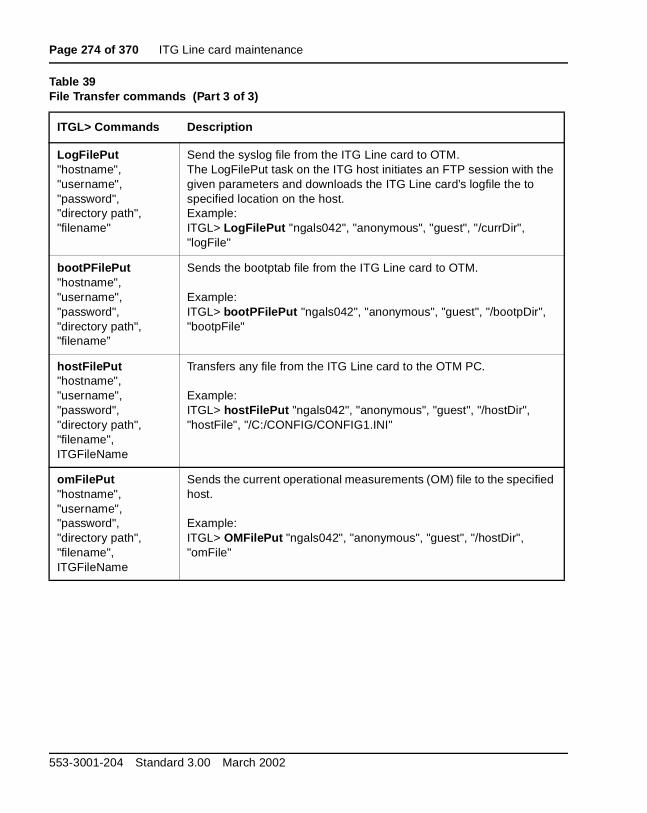
Page 274 of 370 ITG Line card maintenance
LogFilePut "hostname", "username", "password", "directory path", "filename"
Send the syslog file from the ITG Line card to OTM.The LogFilePut task on the ITG host initiates an FTP session with the given parameters and downloads the ITG Line card’s logfile the to specified location on the host.Example:ITGL> LogFilePut "ngals042", "anonymous", "guest", "/currDir", "logFile"
bootPFilePut "hostname", "username", "password", "directory path", "filename”
Sends the bootptab file from the ITG Line card to OTM.
Example:ITGL> bootPFilePut "ngals042", "anonymous", "guest", "/bootpDir", "bootpFile"
hostFilePut "hostname", "username", "password", "directory path", "filename", ITGFileName
Transfers any file from the ITG Line card to the OTM PC.
Example:ITGL> hostFilePut "ngals042", "anonymous", "guest", "/hostDir", "hostFile", "/C:/CONFIG/CONFIG1.INI"
omFilePut "hostname", "username", "password", "directory path", "filename", ITGFileName
Sends the current operational measurements (OM) file to the specified host.
Example:ITGL> OMFilePut "ngals042", "anonymous", "guest", "/hostDir", "omFile"
Table 39File Transfer commands (Part 3 of 3)
ITGL> Commands Description
553-3001-204 Standard 3.00 March 2002

ITG Line card maintenance Page 275 of 370
Table 40 lists the IP configuration ITGL> commands applicable to the ITG Line card.
Table 40IP Configuration commands
ITGL> Command Description
NVRIPSet Sets the IP address in NVRAM.
NVRGWSet Sets the default gateway address in NVRAM.
NVRSMSet Sets the subnet mask in NVRAM.
NVRIPShow Prints the values of the IP parameters that reside in NVRAM.
nvramLeaderSet Sets the leader bit in NVRAM.
nvramLeaderClr Clears the leader bit in NVRAM, but does not erase the IP parameters in NVRAM.
NVRClear Clear IP parameters in NVRAM.
setLeader Sets a leader card, including the IP address, gateway, subnet mask, boot method to static, and leader bit in NVRAM. This one command does all the necessary actions to make a leader.
clearLeader Clears the leader information in NVRAM, sets the boot method to use bootp, and removes the old configuration files. This command makes a leader card into a follower card.
tLanDuplexSet Sets the TLAN ethernet duplex mode.
tLanSpeedSet Sets the TLAN ethernet speed.
ITG Line Description, Installation, and Operation
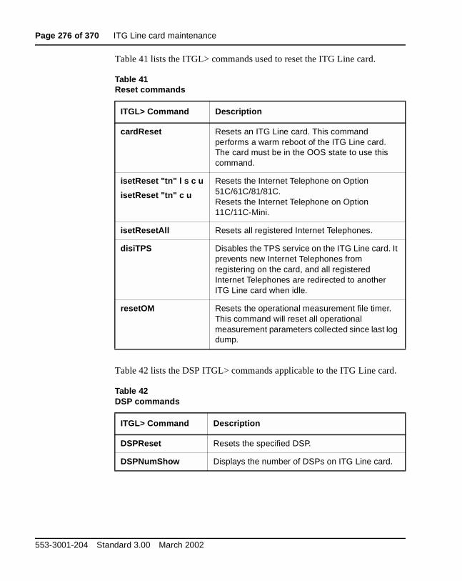
Page 276 of 370 ITG Line card maintenance
Table 41 lists the ITGL> commands used to reset the ITG Line card.
Table 42 lists the DSP ITGL> commands applicable to the ITG Line card.
Table 41Reset commands
ITGL> Command Description
cardReset Resets an ITG Line card. This command performs a warm reboot of the ITG Line card. The card must be in the OOS state to use this command.
isetReset "tn" l s c u
isetReset "tn" c u
Resets the Internet Telephone on Option 51C/61C/81/81C. Resets the Internet Telephone on Option 11C/11C-Mini.
isetResetAll Resets all registered Internet Telephones.
disiTPS Disables the TPS service on the ITG Line card. It prevents new Internet Telephones from registering on the card, and all registered Internet Telephones are redirected to another ITG Line card when idle.
resetOM Resets the operational measurement file timer. This command will reset all operational measurement parameters collected since last log dump.
Table 42DSP commands
ITGL> Command Description
DSPReset Resets the specified DSP.
DSPNumShow Displays the number of DSPs on ITG Line card.
553-3001-204 Standard 3.00 March 2002
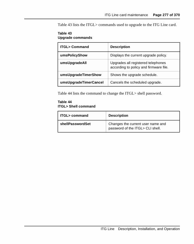
ITG Line card maintenance Page 277 of 370
Table 43 lists the ITGL> commands used to upgrade to the ITG Line card.
Table 44 lists the command to change the ITGL> shell password.
Table 43Upgrade commands
ITGL> Command Description
umsPolicyShow Displays the current upgrade policy.
umsUpgradeAll Upgrades all registered telephones according to policy and firmware file.
umsUpgradeTimerShow Shows the upgrade schedule.
umsUpgradeTimerCancel Cancels the scheduled upgrade.
Table 44ITGL> Shell command
ITGL> command Description
shellPasswordSet Changes the current user name and password of the ITGL> CLI shell.
ITG Line Description, Installation, and Operation
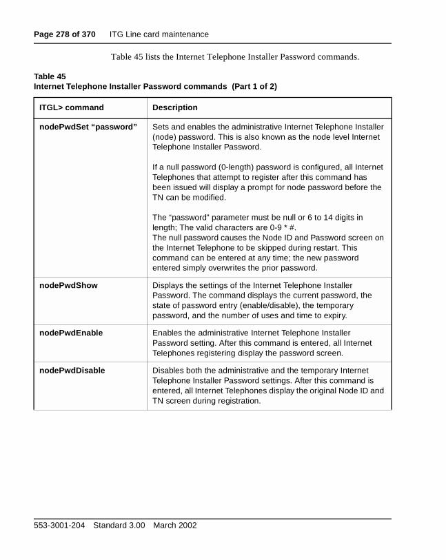
Page 278 of 370 ITG Line card maintenance
Table 45 lists the Internet Telephone Installer Password commands.
Table 45Internet Telephone Installer Password commands (Part 1 of 2)
ITGL> command Description
nodePwdSet “password” Sets and enables the administrative Internet Telephone Installer (node) password. This is also known as the node level Internet Telephone Installer Password.
If a null password (0-length) password is configured, all Internet Telephones that attempt to register after this command has been issued will display a prompt for node password before the TN can be modified.
The “password” parameter must be null or 6 to 14 digits in length; The valid characters are 0-9 * #. The null password causes the Node ID and Password screen on the Internet Telephone to be skipped during restart. This command can be entered at any time; the new password entered simply overwrites the prior password.
nodePwdShow Displays the settings of the Internet Telephone Installer Password. The command displays the current password, the state of password entry (enable/disable), the temporary password, and the number of uses and time to expiry.
nodePwdEnable Enables the administrative Internet Telephone Installer Password setting. After this command is entered, all Internet Telephones registering display the password screen.
nodePwdDisable Disables both the administrative and the temporary Internet Telephone Installer Password settings. After this command is entered, all Internet Telephones display the original Node ID and TN screen during registration.
553-3001-204 Standard 3.00 March 2002

ITG Line card maintenance Page 279 of 370
nodeTempPwdSet “tempPwd”, uses, <time>
Sets the temporary Internet Telephone Installer Password. This password is disabled by default.
The password must be a string 6 to 14 digits in length. A null password cannot be entered. The valid tempPwd characters are 0-9 * #.
The uses parameter is a numeric value from 0-1000. This parameter specifies the number of uses for which the temporary password is valid. The range for the time parameter is 0-240 hours, which is a maximum of 10 days. The time parameter specifies the duration in hours that the password is valid.
• If the uses parameter is set to zero, the time parameter is mandatory. As a result, the password only expires based on time.
• If the uses parameter is non-zero, the time parameter is optional.
• If both the uses and time parameters are entered, the password expires on whichever comes first, that is, uses is reduced to zero or the time has expired.
• If both uses and time are entered and both are set to zero, it is the same as not setting the temporary password at all.
This command can be entered at any time and the new parameters overwrite the existing temporary password’s parameters.
nodeTempPwdClear Deletes the temporary Internet Telephone Installer Password. It also reset the uses and time parameters to zero.
Table 45Internet Telephone Installer Password commands (Part 2 of 2)
ITGL> command Description
ITG Line Description, Installation, and Operation
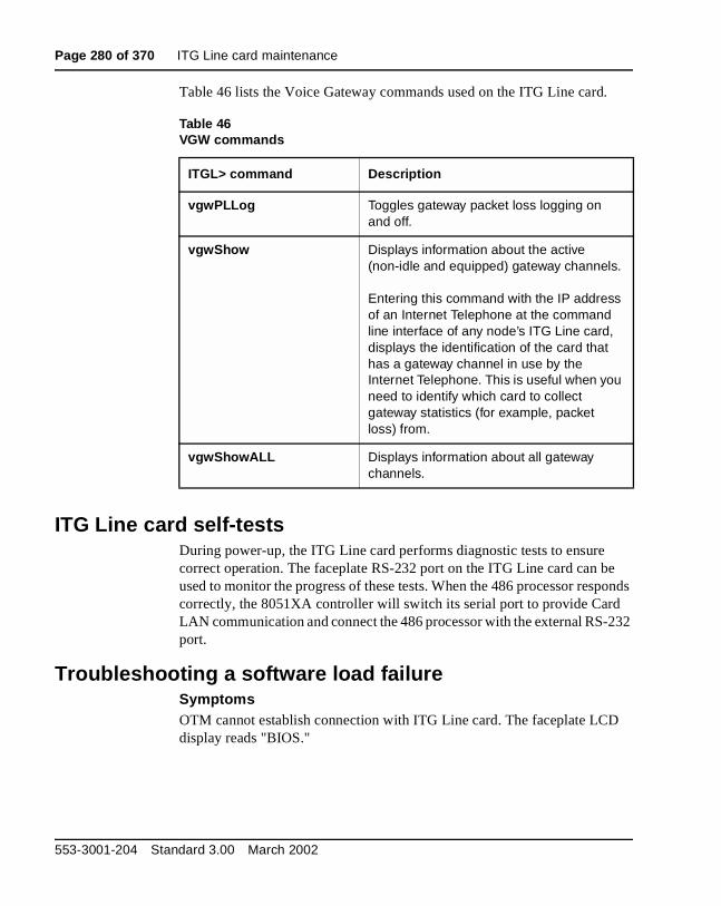
Page 280 of 370 ITG Line card maintenance
Table 46 lists the Voice Gateway commands used on the ITG Line card.
ITG Line card self-testsDuring power-up, the ITG Line card performs diagnostic tests to ensure correct operation. The faceplate RS-232 port on the ITG Line card can be used to monitor the progress of these tests. When the 486 processor responds correctly, the 8051XA controller will switch its serial port to provide Card LAN communication and connect the 486 processor with the external RS-232 port.
Troubleshooting a software load failureSymptoms OTM cannot establish connection with ITG Line card. The faceplate LCD display reads "BIOS."
Table 46VGW commands
ITGL> command Description
vgwPLLog Toggles gateway packet loss logging on and off.
vgwShow Displays information about the active (non-idle and equipped) gateway channels.
Entering this command with the IP address of an Internet Telephone at the command line interface of any node’s ITG Line card, displays the identification of the card that has a gateway channel in use by the Internet Telephone. This is useful when you need to identify which card to collect gateway statistics (for example, packet loss) from.
vgwShowALL Displays information about all gateway channels.
553-3001-204 Standard 3.00 March 2002

ITG Line card maintenance Page 281 of 370
ProblemThe ITG Line card has booted the BIOS load.
DiagnosisIn the event of a failure to load and run the ITG software, the ITG Line card defaults to the BIOS load. This load consists of a prompt that allows commands to reload the ITG software and reboot (see below).
There are three known reasons that can cause the failure to load the ITG software:
• Not enough memory due to a faulty or missing SIMM.
• Corruption of the ITG software image in flash memory.
• The escape sequence to boot from the BIOS has been inadvertently sent down the serial line due to noise.
To determine which of the three causes caused the ITG load failure, reboot and monitor the booting sequence through the serial port. Capture the booting sequence to aid in communication with technical support personnel.
Examples of booting sequencesCase 1The following excerpt from the booting sequence indicates the amount of memory onboard.
Memory ConfigurationOnboard: 4MBSIMM: 16MBTotal: 20MB
In the absence or failure of the SIMM, the total memory is 4MB, which is not enough to support the ITG application.
ITG Line Description, Installation, and Operation
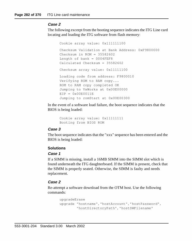
Page 282 of 370 ITG Line card maintenance
Case 2The following excerpt from the booting sequence indicates the ITG Line card locating and loading the ITG software from flash memory:
Cookie array value: 0x111111100
Checksum Validation at Bank Address: 0xF9800000Checksum in ROM = 35582602Length of bank = 0004FEF8Calculated Checksum = 35582602
Checksum array value: 0x11111100
Loading code from address: F9800010Verifying ROM to RAM copy...ROM to RAM copy completed OKJumping to VxWorks at 0x00E00000EIP = 0x00E0011EJumping to romStart at 0x00E00300
In the event of a software load failure, the boot sequence indicates that the BIOS is being loaded:
Cookie array value: 0x11111111Booting from BIOS ROM
Case 3 The boot sequence indicates that the "xxx" sequence has been entered and the BIOS is being loaded:
SolutionsCase 1If a SIMM is missing, install a 16MB SIMM into the SIMM slot which is found underneath the ITG daughterboard. If the SIMM is present, check that the SIMM is properly seated. Otherwise, the SIMM is faulty and needs replacement.
Case 2Re-attempt a software download from the OTM host. Use the following commands:
upgradeEraseupgrade "hostname","hostAccount","hostPassword", "hostDirectoryPath","hostSWFilename"
553-3001-204 Standard 3.00 March 2002

ITG Line card maintenance Page 283 of 370
After the software loads to flash, reboot the card:
sysReboot
If the failure to load the ITG software into RAM persists, then the flash device is faulty. Replace the ITG Line card.
Case 3The escape sequence "xxx" is rarely transmitted. Reboot the card.
Warm rebooting the ITG Line cardThe following ITG Line CLI command performs a warm reboot of an out-of-service ITG Line card: cardReset
Test the ITG Line card DSPsAt the ITGL> CLI, the following two tests can be performed on the ITG DSPs:
• To run a self-test on the DSP daughterboard: DSPselfTest
Note: If the DSP self-test fails, the ITG Line card must be replaced.
• To run a PCM loopback test, a Send loopback test, or a Receive loopback test on the DSP daughterboard, respectively:
DSPPcmLpbkTestOn (“DSPPcmLpbkTestOff” to stop the test)DSPSndLpbkTestOn (“DSPSndLpbkTestOff” to stop the test)DSPRcvLpbkTestOn (“DSPRcvLpbkTestOff” to stop the test)
Note: The DSPs and all associated ports must be disabled before performing these tests.
Work with alarm and log filesAlarm and log file output is turned on using the ITGL> CLI. The following commands may be performed at the ITGL> prompt:
• To turn on or turn off the error log file, type: logFileOn or logFileOff.
• To display the modes of all log files and alarms, type: logFileShow.
ITG Line Description, Installation, and Operation

Page 284 of 370 ITG Line card maintenance
Troubleshooting Internet Telephone InstallationIf you are unable to install Internet Telephones because you are not prompted for node ID or TN:
• Log in to one ITG Line card in the node.
• Type the nodePwdShow command at the ITGL> prompt.
• If the administrative password is enabled (PwdEna=Yes) and there is a null (zero-length) password, that is, the Pwd field is blank, then you will not be able to install Internet Telephone on that ITG Line card.
• Use the nodePwdSet “password” command to set the administrative password and to allow phones to be installed. Ensure the “password” parameter is included.
NodeID=======123
PwdEna========Yes
Pwd=========
TmpPwd=========
Uses========
Timeout==========0d 0h 0m 0s
553-3001-204 Standard 3.00 March 2002
Page 285 of 370
296
Appendix A: I/O, maintenance, and extender cable description
ContentsThis section contains information on the following topics:
Overview . . . . . . . . . . . . . . . . . . . . . . . . . . . . . . . . . . . . . . . . . . . . . . . . 285
NTMF94EA I/O cable . .. . . . . . . . . . . . . . . . . . . . . . . . . . . . . . . . . . . . 285
Connector pin assignments . . . . . . . . . . . . . . . . . . . . . . . . . . . . . . . . . . 287Prevent ground loops on connection to external customer LAN equipment . . . . . . . . . . . . . . . . . . . . . . . . . . . . . . . . . . . . . . . . 290
NTAG81CA maintenance cable description . . . . . . . . . . . . . . . . . . . . . 291
NTAG81BA maintenance extender cable . . . . . . . . . . . . . . . . . . . . . . . 292
Replace cable NT8D81BA with NT8D81AA . .. . . . . . . . . . . . . . . . . . 293Tools list . . . . . . . . . . . . . . . . . . . . . . . . . . . . . . . . . . . . . . . . . . . . . . 294
OverviewThis appendix describes the NTMF94EA, NTAG81CA, and NTAG81BA cables and explains how to replace the NT8D81BA backplane ribbon cable and install the NTCW84JA filter, if required.
NTMF94EA I/O cableThe NTMF94EA provides the ELAN, TLAN ports that provide the interface from the IP Line card to the customer’s network equipment, and one DB9 serial port that provides serial connection between the card and the customer PC or TTY (see Figure 48 on page 287).
ITG Line Description, Installation, and Operation

Page 286 of 370 Appendix A: I/O, maintenance, and extender cable description
It is important to use the mounting screw provided to secure the top of the NTMF94EA cable 25-pair Amphenol connector to the Meridian 1 and Succession Communication Server for Enterprise 1000. The screw ties the LAN cable shield to the Meridian 1 and Succession CSE 1000 frame ground for EMC compliance.
The NTMF94EA cable provides a factory installed, shielded, RJ-45 to RJ-45 coupler at the end of both the ELAN and TLAN ports. An unshielded coupler is provided to prevent ground loops (if required). Refer to “Prevent ground loops on connection to external customer LAN equipment” on page 290, to determine if you have to use the unshielded coupler. Both ends of the RJ-45 ports of the cables are labeled as to which is the TLAN and which is the ELAN. The ports provide the connection point to the customer’s ELAN and TLAN equipment. You must use shielded Category 5 cable to connect to the customer’s equipment.
To improve EMC performance, use standard cable ties to bundle all LAN cables as they route out of the system.
Note: To avoid damage to Category 5 cable, do not overtighten cable ties.
553-3001-204 Standard 3.00 March 2002
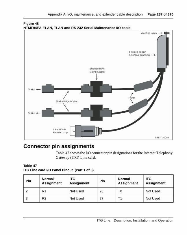
Appendix A: I/O, maintenance, and extender cable description Page 287 of 370
Figure 48NTMF94EA ELAN, TLAN and RS-232 Serial Maintenance I/O cable
Connector pin assignmentsTable 47 shows the I/O connector pin designations for the Internet Telephony Gateway (ITG) Line card.
Table 47ITG Line card I/O Panel Pinout (Part 1 of 3)
PinNormal Assignment
ITG Assignment
PinNormal Assignment
ITG Assignment
2 R1 Not Used 26 T0 Not Used
3 R2 Not Used 27 T1 Not Used
Mounting Screw
Shielded 25-pairAmphenol connector
Shielded RJ45Mating Coupler
Shielded RJ45 Cable
Ferrite
9 Pin D-SubFemale
To Hub
To Hub
553-ITG0006
ITG Line Description, Installation, and Operation
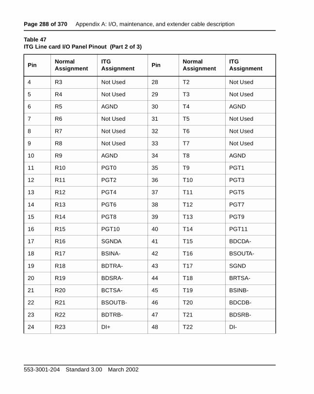
Page 288 of 370 Appendix A: I/O, maintenance, and extender cable description
4 R3 Not Used 28 T2 Not Used
5 R4 Not Used 29 T3 Not Used
6 R5 AGND 30 T4 AGND
7 R6 Not Used 31 T5 Not Used
8 R7 Not Used 32 T6 Not Used
9 R8 Not Used 33 T7 Not Used
10 R9 AGND 34 T8 AGND
11 R10 PGT0 35 T9 PGT1
12 R11 PGT2 36 T10 PGT3
13 R12 PGT4 37 T11 PGT5
14 R13 PGT6 38 T12 PGT7
15 R14 PGT8 39 T13 PGT9
16 R15 PGT10 40 T14 PGT11
17 R16 SGNDA 41 T15 BDCDA-
18 R17 BSINA- 42 T16 BSOUTA-
19 R18 BDTRA- 43 T17 SGND
20 R19 BDSRA- 44 T18 BRTSA-
21 R20 BCTSA- 45 T19 BSINB-
22 R21 BSOUTB- 46 T20 BDCDB-
23 R22 BDTRB- 47 T21 BDSRB-
24 R23 DI+ 48 T22 DI-
Table 47ITG Line card I/O Panel Pinout (Part 2 of 3)
PinNormal Assignment
ITG Assignment Pin
Normal Assignment
ITG Assignment
553-3001-204 Standard 3.00 March 2002
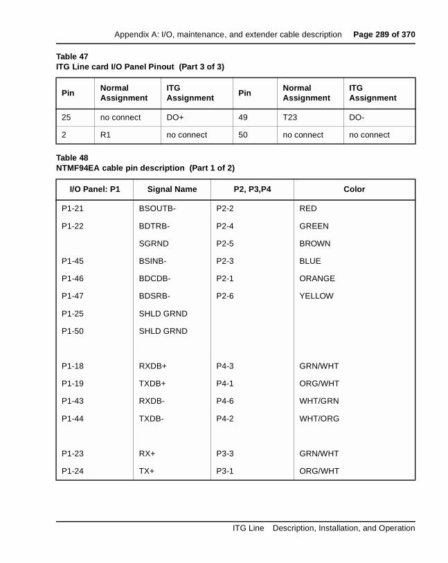
Appendix A: I/O, maintenance, and extender cable description Page 289 of 370
25 no connect DO+ 49 T23 DO-
2 R1 no connect 50 no connect no connect
Table 48NTMF94EA cable pin description (Part 1 of 2)
I/O Panel: P1 Signal Name P2, P3,P4 Color
P1-21 BSOUTB- P2-2 RED
P1-22 BDTRB- P2-4 GREEN
SGRND P2-5 BROWN
P1-45 BSINB- P2-3 BLUE
P1-46 BDCDB- P2-1 ORANGE
P1-47 BDSRB- P2-6 YELLOW
P1-25 SHLD GRND
P1-50 SHLD GRND
P1-18 RXDB+ P4-3 GRN/WHT
P1-19 TXDB+ P4-1 ORG/WHT
P1-43 RXDB- P4-6 WHT/GRN
P1-44 TXDB- P4-2 WHT/ORG
P1-23 RX+ P3-3 GRN/WHT
P1-24 TX+ P3-1 ORG/WHT
Table 47ITG Line card I/O Panel Pinout (Part 3 of 3)
PinNormal Assignment
ITG Assignment Pin
Normal Assignment
ITG Assignment
ITG Line Description, Installation, and Operation

Page 290 of 370 Appendix A: I/O, maintenance, and extender cable description
Prevent ground loops on connection to external customer LAN equipment
The shielded RJ-45 coupler is the connection point for the customer’s shielded Category 5 LAN cable to the hub, switch, or router supporting the TLAN and ELAN. You must use shielded Category 5 RJ-45 cable to connect to the customer’s TLAN/ELAN equipment.
1 Connect the customer-provided shielded Category 5 LAN cable to the external LAN equipment. Ensure that the external LAN equipment is powered-up.
2 Use an ohmmeter to measure resistance to ground between the free end of the shielded RJ-45 cable and building ground.
The ohmmeter must measure Open to ground before plugging it into the shielded RJ-45 coupler on the end of the NTMF94EA.
3 If it does not measure Open, you must install the unshielded RJ-45 coupler (provided) on the end of the NTMF94EA to prevent ground loops to external LAN equipment.
P1-48 RX- P3-6 WHT/GRN
P1-49 TX- P3-2 WHT/ORG
P1-25 SHLD GRND BARE
P1-50 SHLD GRND BARE
WARNINGThe serial maintenance ports on the faceplate connector and the DB-9 female connector of the NTMF9DA cable assembly are identical. Do not connect a serial device to both access points simultaneously. This will result in incorrect and unpredictable operation of the IP Line card.
Table 48NTMF94EA cable pin description (Part 2 of 2)
I/O Panel: P1 Signal Name P2, P3,P4 Color
553-3001-204 Standard 3.00 March 2002

Appendix A: I/O, maintenance, and extender cable description Page 291 of 370
NTAG81CA maintenance cable descriptionThe NTAG81CA maintenance cable (see Figure 49) is connected between the 9-pin D-type RS232 input on a standard PC, and the MAINT connector on the NT8R17AB faceplate or through the I/O cable serial port. The NTAG91CA maintenance cable pin description is outlined in Table 49.
Figure 49NTAG81CA Maintenance cable
Table 49NTAG81CA maintenance cable pin description
Signals(MIX Side)
8-pin Mini-DIN(MIX Side)
Male
9-pin D-Sub(PC Side)Female
Signals(PC Side)
DTRB- 1 6 DSR-
SOUTB- 2 2 SIN-
SINB- 3 3 SOUT-
GND 4 5 GND
SINA- 5 nc nc
CTSA- 6 nc nc
SOUTA- 7 nc nc
DTRA- 8 nc nc
DIN-8
DB-9 Female
553-ITG0007
ITG Line Description, Installation, and Operation
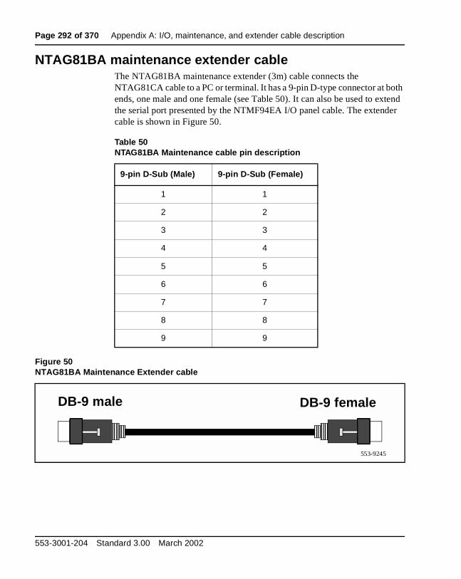
Page 292 of 370 Appendix A: I/O, maintenance, and extender cable description
NTAG81BA maintenance extender cableThe NTAG81BA maintenance extender (3m) cable connects the NTAG81CA cable to a PC or terminal. It has a 9-pin D-type connector at both ends, one male and one female (see Table 50). It can also be used to extend the serial port presented by the NTMF94EA I/O panel cable. The extender cable is shown in Figure 50.
Figure 50NTAG81BA Maintenance Extender cable
Table 50NTAG81BA Maintenance cable pin description
9-pin D-Sub (Male) 9-pin D-Sub (Female)
1 1
2 2
3 3
4 4
5 5
6 6
7 7
8 8
9 9
DB-9 femaleDB-9 male
553-9245
553-3001-204 Standard 3.00 March 2002

Appendix A: I/O, maintenance, and extender cable description Page 293 of 370
Replace cable NT8D81BA with NT8D81AAThis procedure explains how to replace the NT8D81BA cable with the NT8D81AA cable and how to install the NTCW84JA special IPE filter.
Cables are designated by the letter of the I/O panel cutout, such as A, B, and C, where the 50-pin cable connector is attached. Each cable has three 20-pin connectors (16 positions are used), designated 1, 2, and 3, that attach to the backplane. Using the designations described, the backplane ends of the first cable are referred to as A-1, A-2, and A-3. The locations of the cable connectors on the backplane are designated by the slot number (L0 through L9 for NT8D11, L0 through L15 for NT8D37) and the shroud row (1, 2, and 3). Using these designations, the slot positions in the first slot are referred to as L0-1, L0-2, and L0-3.
In NT8D37BA and NT8D37EC (and later vintage) IPE Modules, all 16 IPE card slots support 24-pair cable connections. Table 51 shows the cable connections from the backplane to the inside of the I/O panel.
Table 51NT8D37 cable connections
Backplane slots–shroud rows I/O panel/cable designation
L0–1, 2, 3L1–1, 2, 3L2–1, 2, 3L3–1, 2, 3L4–1, 2, 3L5–1, 2, 3L6–1, 2, 3L7–1, 2, 3L8–1, 2, 3L9–1, 2, 3L10–1, 2, 3L11–1, 2, 3L12–1, 2, 3L13–1, 2, 3L14–1, 2, 3L15–1, 2, 3
ABCDEFGHKLMNRSTU
ITG Line Description, Installation, and Operation

Page 294 of 370 Appendix A: I/O, maintenance, and extender cable description
Figure 51 shows the designations for the backplane end of the cables, the backplane slot designations for the cable connections, and the associated network segments for the backplane slots.
Figure 51Backplane slot designations
Tools listThe following tools are required to perform this procedure.
• Ty-wrap cutter
• Ty-wraps
• Needle nose pliers
• Slotted screwdriver
Procedure 48Removing an NT8D81BA cable
1 Identify the I/O panel and backplane designation that corresponds to the LEFT slot of the pair of card slots, viewed from the front, in which you installed the ITG ISL Trunk card.
2 Disconnect the filter from the I/O panel using a screwdriver and needle nose pliers. Retain the fasteners.
Segment 0L15 L14 L13 L12 L11 L10 L9 L8 L7 L6 L5 L4 L3 L2 L1 L0
A-1
B-3
C-2
E-3
F-2
E-1 B-1
A-2
A-3
B-2
C-1
C-3
E-2
F-1
F-3
1
2
3
Sh
rou
d r
ow
553-5391
L-1R-1S-1T-1 M-1
Segment 1Segment 2Segment 3
SL0
SL1
SL2
SL3
L16
G-1
G-3
G-2L-2
L-3
M-2
M-3
R-1
R-1
K-1
K-2
K-3
S-2
S-3
T-2
T-3
D-1
D-2
D-3
H-1
H-2
H-3
N-1
N-2
N-3
U-1
U-2
U-3
553-3001-204 Standard 3.00 March 2002
Appendix A: I/O, maintenance, and extender cable description Page 295 of 370
3 Power down the IPE shelf.
4 Remove the IPE module I/O safety panel.
5 To remove the ribbon cables from IPE backplane, apply gentle pressure on the tab on the right side of the shroud while pulling on the connector until it pulls free from the shroud.
Remove connector 1 first, then remove connectors 2 and 3.
6 Discard NT8D81BA cable.
—————————— End of Procedure ——————————
Procedure 49Installing an NTCW84JA filter and NT8D81AA cable
1 Install NTCW84JA special IPE filter connector in the vacant I/O panel slot using retained hardware.
2 Install NT8D81AA ribbon cable connectors in the IPE module backplane shroud. Be sure to install the connector so the label is facing right with the arrow pointing up and the connector is fully engaged into the shroud:
a. Install connector 1, (labeled UP1^) into backplane shroud 1.
b. Install connector 2, (labeled UP2^) into backplane shroud 2.
c. Install connector 3, (labeled UP3^) into backplane shroud 3.
3 Dress the ribbon cables back individually inside the rear of IPE module and restore the original arrangement. Start with the cables that are going to be underneath.
4 Attach NTCW84JA special IPE filter to NT8D81AA 50-pin connector using bail clips.
5 Restore power to the IPE module.
6 Replace the I/O safety panel.
—————————— End of Procedure ——————————
ITG Line Description, Installation, and Operation

Page 296 of 370 Appendix A: I/O, maintenance, and extender cable description
553-3001-204 Standard 3.00 March 2002

Page 297 of 370
316
Appendix B: RM356 modem routerContents
This section contains information on the following topics:
Overview . . . . . . . . . . . . . . . . . . . . . . . . . . . . . . . . . . . . . . . . . . . . . . . . 297
RM356 modem router security features . . . . . . . . . . . . . . . . . . . . . . . . 298
Install the RM356 modem router . . . . . . . . . . . . . . . . . . . . . . . . . . . . . 299
Configure the RM356 modem router by the manager menu . . . . . . . . 300
RM356 modem router manager menu description . . . . . . . . . . . . . . . . 307Application notes on Meridian 1 and Succession CSE 1000 ELAN installation . .. . . . . . . . . . . . . . . . . . . . . . . . . . . . . . . . . . . . . 307
OverviewManagement and support of the ITG network depend on IP networking protocols including SNMP, FTP, and Telnet. Install a modem router on the Meridian 1 and Succession Communication Server for Enterprise 1000 site LAN (called the embedded LAN or ELAN as opposed to the customer's enterprise network or C-LAN) in order to provide remote support access for ITG and other IP-enabled Nortel Networks products.
The Netgear RM356 modem router integrates the functions of a V.90 modem, a PPP remote access server, an IP router, and a 4-port 10BaseT Ethernet hub, and provides a range of security features configured to comply with the customer's data network security policy. Do not install a modem router on the ELAN without the explicit approval of the customer's IP network manager. The RM356 modem router is not secure unless it is configured correctly according to the customer's network security policy and practices. Figure 52 shows an example of a remote network.
ITG Line Description, Installation, and Operation

Page 298 of 370 Appendix B: RM356 modem router
RM356 modem router security featuresThe security features of the RM356 modem router include:
• Password Authentication Protocol (PAP) for dial-in PPP connection
• RM356 manager password
• CLID for dial-in user authentication (requires C.O. line with Calling Line ID)
• Callback for dial-in user authentication
• Dial-in user profiles
• Static IP routing
• IP Packet Filtering
• Idle timeout disconnect for dial-in PPP connection
Figure 52Remote support using Netgear RM356 modem router
T-LAN
E-LANCore 0
Core 1
MAT / OTM
PSTN
Netgear RM 356Modem Router
Hub
Router
Hub
PC
I2004
DHCP Server
C -LAN
553-3001-204 Standard 3.00 March 2002
Appendix B: RM356 modem router Page 299 of 370
Install the RM356 modem routerProcedure 50Installing the RM356 modem router
1 Place the modem router at a conveniently visible and physically secure location near an AC power outlet, an analog telephone line, and a 10BaseT Ethernet cable.
Up to four hosts or hubs can be connected to the integrated 10BaseT hub in the rear of the RM356 modem router.
2 Use shielded Cat5 10BaseT Ethernet cables to connect the modem router to the Management interface of up to four Internet Telephony Gateway (ITG) Line cards. Other IP-enabled Nortel Networks products on the ELAN can be connected to the RM356 modem router, including the Meridian 1 PBX, a local Optivity Telephone Manager (OTM) 1.0 PC, Symposium Call Center Server, and Call Pilot.
Note: The up-link connection to an additional ELAN hub or optional C-LAN gateway requires either a cross-over 10BaseT Ethernet cable, or a special up-link port on the 10BaseT hub to which the RM356 is connected.
3 Connect the modem router to the AC power source. The power LED will light. After several seconds, the test LED flashes slowly four times, then stays off.
For each of the four 10BaseT ports on the integrated hub there is a link/data LED that is lit steadily to indicate a good received link (if a cable is connected to a host or hub), or flashing, to indicate data received on the LAN.
4 Connect the RJ45 plug end of the local manager cable to the RS232 Manager port RJ45 jack on the rear of the modem router.
5 Connect the other end of the manager cable to an RS232 terminal or PC COM port configured for the following communication parameters: 9600 bps, 8, none, and 1.
6 The local maintenance cable connects directly to data terminal equipment (DTE).
Note: The analog telephone line must be either a C.O. line or a PBX extension with a Direct Inward Dialing (DID) number, whichever complies with the customer's network security policy.
—————————— End of Procedure ——————————
ITG Line Description, Installation, and Operation

Page 300 of 370 Appendix B: RM356 modem router
Configure the RM356 modem router by the manager menuThis procedure can be performed from a terminal or PC connected to the local RS232 manager port on the rear of the modem router. Alternatively the manager menu can be accessed by Telnet after the IP addressing and routing have been set up initially from the local manager port.
Use the following keys in the RM356 manager menu:
• the arrow keys to navigate
• the spacebar key to toggle pre-defined configuration values for a field
• the Enter key saves data changes to ROM and exits the current menu
• the Esc key exits the current menu without saving changes
• enter menu selection number when prompted to display a sub-menu, configuration form, or command prompts
Procedure 51Configuring the RM356 modem router
1 Press the Enter key from the terminal or manager menu. The Enter Password: prompt is displayed for 10 seconds.
2 Enter the default RM356 manager password 1234. The RM356 Main Menu is displayed. See page 307 for a complete view of the RM356 modem router menus.
RM356 Main Menu
Getting Started
1. General Setup
2. MODEM Setup
3. Ethernet Setup
4. Internet Access Setup
Advanced Management
21. Filter Set Configuration
23. System Password
24. System Maintenance
Advanced Applications
11. Remote Node Setup
12. Static Routing Setup
13. Default Dial-in Setup
14. Dial-in User Setup
99. Exit
Enter Menu Selection Number:
553-3001-204 Standard 3.00 March 2002
Appendix B: RM356 modem router Page 301 of 370
3 At the Enter Menu Selection Number: prompt, enter menu selection number 1 to access the General Setup under Getting Started. The Menu 1 - General Setup sub-menu is displayed.
Menu 1 - General Setup
System Name= Room_304_RCH_Training_CenterLocation= Sherman Ave., Richardson, TXContact Person's Name= John Smith, 972 555-1212
Press ENTER to Confirm or ESC to Cancel:
4 Under General Setup, type in the System Name (19 characters, no spaces), Location, and Contact Person's Name for the Meridian 1 and Succession CSE 1000 site.
Use the up and down arrow keys to move the cursor to the prompt Press ENTER to Confirm or ESC to Cancel: at the bottom of the menu. Press Enter to confirm and save data to ROM.
5 Enter menu selection number 2 to access the MODEM Setup under the Getting Started section. The Menu 2 - Modem Setup sub-menu is displayed.
Menu 2 - MODEM Setup
Modem Name= MODEMActive= YesDirection= IncomingPhone Number=Advanced Setup= No
Press ENTER to Confirm or ESC to Cancel:
6 Use the arrow keys to navigate and space bar to toggle values. Type in Modem Name. Set Active= Yes and Direction= Incoming. Type in the modem router's Phone Number for reference.
Press Enter to confirm and save data to ROM.
7 Enter menu selection number 3, to access Ethernet Set under the Getting Started section. The Menu 3: Ethernet Setup sub-menu is displayed.
Menu 3 - Ethernet Setup
1. General Setup2. TCP/IP and DHCP Setup
Enter Menu Selection Number:
ITG Line Description, Installation, and Operation

Page 302 of 370 Appendix B: RM356 modem router
8 Enter menu selection 2, under Ethernet Setup. The Menu 3.2 - TCP/IP and DHCP Ethernet Setup is displayed.
Menu 3.2 - TCP/IP and DHCP Ethernet Setup
DHCP Setup:DHCP= NoneClient IP Pool Starting Address= N/ASize of Client IP Pool= N/APrimary DNS Server= N/ASecondary DNS Server= N/A
TCP/IP Setup:IP Address= 47.177.16.254IP Subnet Mask= 255.255.255.0RIP Direction= NoneVersion= RIP-2B
Press ENTER to Confirm or ESC to Cancel:
Press Space Bar to Toggle.
9 Under DHCP Setup, toggle DHCP= None using the space bar.
Under TCP/IP Setup, type in the IP Address and the IP Subnet Mask for the modem router's Ethernet interface on the ELAN. Toggle RIP Direction= None.
Press Enter to confirm and save data to ROM, then press Esc to return to the RM356 Main Menu.
10 Enter menu selection number 12, under the Advanced Applications section. The Menu 12 - Static Route Setup sub-menu is displayed.
Menu 12 - Static Route Setup
1. DefaultGW2. ________3. ________4. ________Enter Menu Selection Number:
553-3001-204 Standard 3.00 March 2002

Appendix B: RM356 modem router Page 303 of 370
Note 1: If firewall security is properly configured in the customer's Management GW router, and if the modem router is permitted access over the C-LAN to other ITG Line nodes on remote ELANs, define a default network route pointing to the Management GW IP address on the local ELAN. Alternatively, define up to four different static network routes or host routes in the modem router to limit routing access from the modem router to the C-LAN.
Note 2: To prevent access from the modem router to the C-LAN through the Management GW router on the ELAN, disable RIP by setting RIP Direction=None, and remove all static routes or disable a particular static route by setting Active=No.
11 Enter menu selection number 1 to edit the first static route. Menu 12.1 - Edit IP Static Route is displayed.
Menu 12.1 - Edit IP Static Route
Route #: 1Route Name= DefaultGWActive= YesDestination IP Address= 0.0.0.0IP Subnet Mask= 0.0.0.0Gateway IP Address= 47.177.16.1Metric= 2Private= No
Press ENTER to Confirm or ESC to Cancel:
12 Type in a descriptive Route Name using no spaces, for example, DefaultGW. Toggle Active= Yes/No for security purposes. The Gateway IP Address is the Management GW IP address on the ELAN where the modem router is connected.
Press Enter to confirm and save data to ROM, then press Esc to return from the sub-menu to the RM356 Main Menu.
ITG Line Description, Installation, and Operation
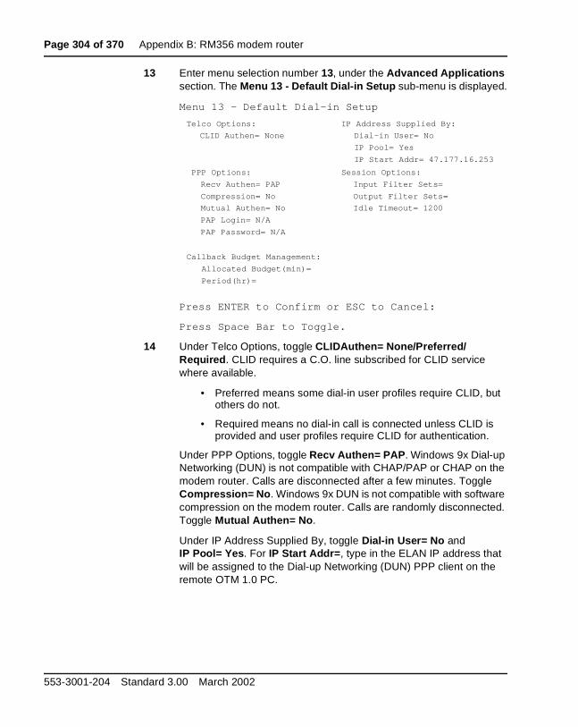
Page 304 of 370 Appendix B: RM356 modem router
13 Enter menu selection number 13, under the Advanced Applications section. The Menu 13 - Default Dial-in Setup sub-menu is displayed.
Menu 13 - Default Dial-in Setup
Press ENTER to Confirm or ESC to Cancel:
Press Space Bar to Toggle.
14 Under Telco Options, toggle CLIDAuthen= None/Preferred/ Required. CLID requires a C.O. line subscribed for CLID service where available.
• Preferred means some dial-in user profiles require CLID, but others do not.
• Required means no dial-in call is connected unless CLID is provided and user profiles require CLID for authentication.
Under PPP Options, toggle Recv Authen= PAP. Windows 9x Dial-up Networking (DUN) is not compatible with CHAP/PAP or CHAP on the modem router. Calls are disconnected after a few minutes. Toggle Compression= No. Windows 9x DUN is not compatible with software compression on the modem router. Calls are randomly disconnected. Toggle Mutual Authen= No.
Under IP Address Supplied By, toggle Dial-in User= No and IP Pool= Yes. For IP Start Addr=, type in the ELAN IP address that will be assigned to the Dial-up Networking (DUN) PPP client on the remote OTM 1.0 PC.
Telco Options:
CLID Authen= None
IP Address Supplied By:
Dial-in User= No
IP Pool= Yes
IP Start Addr= 47.177.16.253
PPP Options:
Recv Authen= PAP
Compression= No
Mutual Authen= No
PAP Login= N/A
PAP Password= N/A
Session Options:
Input Filter Sets=
Output Filter Sets=
Idle Timeout= 1200
Callback Budget Management:
Allocated Budget(min)=
Period(hr)=
553-3001-204 Standard 3.00 March 2002
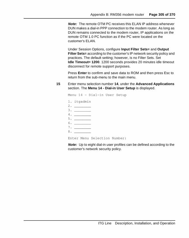
Appendix B: RM356 modem router Page 305 of 370
Note: The remote OTM PC receives this ELAN IP address whenever DUN makes a dial-in PPP connection to the modem router. As long as DUN remains connected to the modem router, IP applications on the remote OTM 1.0 PC function as if the PC were located on the customer's ELAN.
Under Session Options, configure Input Filter Sets= and Output Filter Sets= according to the customer's IP network security policy and practices. The default setting; however, is no Filter Sets. Set Idle Timeout= 1200. 1200 seconds provides 20 minutes idle timeout disconnect for remote support purposes.
Press Enter to confirm and save data to ROM and then press Esc to return from the sub-menu to the main menu.
15 Enter menu selection number 14, under the Advanced Applications section. The Menu 14 - Dial-in User Setup is displayed.
Menu 14 - Dial-in User Setup
1. itgadmin2. ________3. ________4. ________5. ________6. ________7. ________8. ________
Enter Menu Selection Number:
Note: Up to eight dial-in user profiles can be defined according to the customer's network security policy.
ITG Line Description, Installation, and Operation
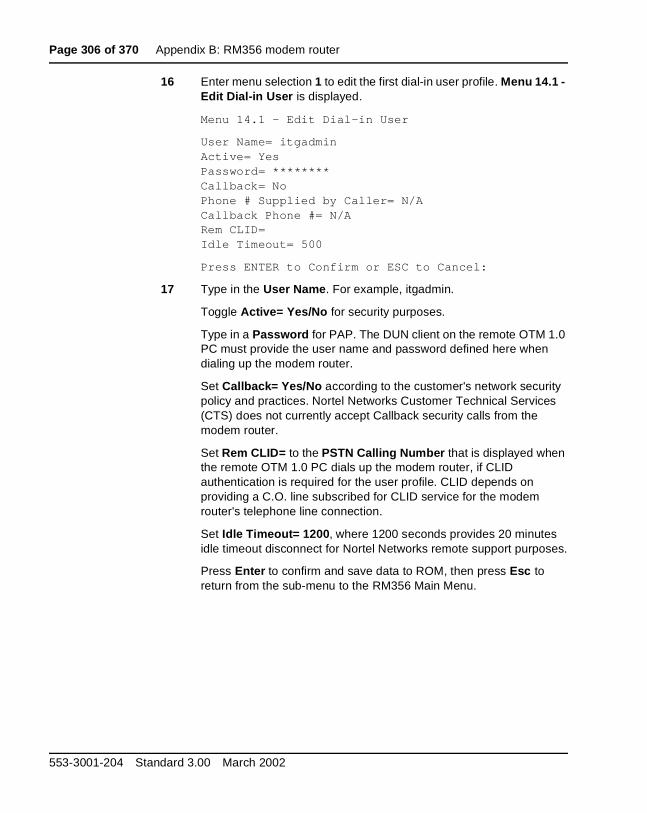
Page 306 of 370 Appendix B: RM356 modem router
16 Enter menu selection 1 to edit the first dial-in user profile. Menu 14.1 - Edit Dial-in User is displayed.
Menu 14.1 - Edit Dial-in User
User Name= itgadminActive= YesPassword= ********Callback= NoPhone # Supplied by Caller= N/ACallback Phone #= N/ARem CLID=Idle Timeout= 500
Press ENTER to Confirm or ESC to Cancel:
17 Type in the User Name. For example, itgadmin.
Toggle Active= Yes/No for security purposes.
Type in a Password for PAP. The DUN client on the remote OTM 1.0 PC must provide the user name and password defined here when dialing up the modem router.
Set Callback= Yes/No according to the customer's network security policy and practices. Nortel Networks Customer Technical Services (CTS) does not currently accept Callback security calls from the modem router.
Set Rem CLID= to the PSTN Calling Number that is displayed when the remote OTM 1.0 PC dials up the modem router, if CLID authentication is required for the user profile. CLID depends on providing a C.O. line subscribed for CLID service for the modem router's telephone line connection.
Set Idle Timeout= 1200, where 1200 seconds provides 20 minutes idle timeout disconnect for Nortel Networks remote support purposes.
Press Enter to confirm and save data to ROM, then press Esc to return from the sub-menu to the RM356 Main Menu.
553-3001-204 Standard 3.00 March 2002

Appendix B: RM356 modem router Page 307 of 370
18 Enter menu selection number 23, under the Advanced Management section of the RM356 Main Menu. Menu 23 - System Password is displayed.
Menu 23 - System Password
Old Password= ?New Password= ?Retype to confirm= ?
Enter here to CONFIRM or ESC to CANCEL:
19 Type in the Old Password. Navigate down and type a New Password. Navigate down to Retype to confirm and then retype the new password.
Press Enter to save the save the changes.
Note: Never leave the RM356 system manager password defaulted to 1234 after the modem router has been installed and configured on the ELAN. The modem router's security features are ineffective if the manager password is not changed on a regular basis according to good network security practices.
—————————— End of Procedure ——————————
RM356 modem router manager menu descriptionApplication notes on Meridian 1 and Succession CSE 1000 ELAN installation
This section displays the various menus of the RM356 modem router:
RM356 Main Menu
Getting Started Advanced Management
1. General Setup 21. Filter Set Configuration
2. MODEM Setup
3. Ethernet Setup 23. System Password
4. Internet Access Setup 24. System Maintenance
Advanced Applications
11. Remote Node Setup
12. Static Routing Setup
13. Default Dial-in Setup
ITG Line Description, Installation, and Operation
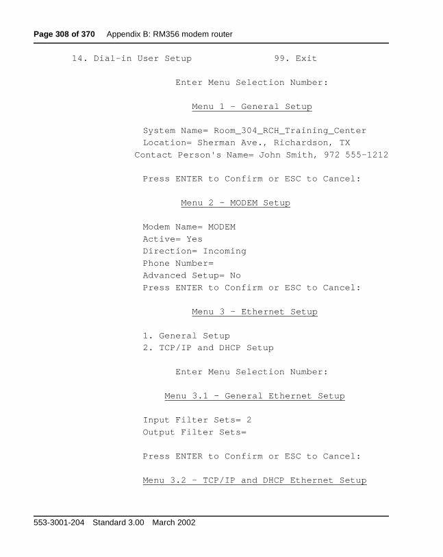
Page 308 of 370 Appendix B: RM356 modem router
14. Dial-in User Setup 99. Exit
Enter Menu Selection Number:
Menu 1 - General Setup
System Name= Room_304_RCH_Training_Center
Location= Sherman Ave., Richardson, TX
Contact Person's Name= John Smith, 972 555-1212
Press ENTER to Confirm or ESC to Cancel:
Menu 2 - MODEM Setup
Modem Name= MODEM
Active= Yes
Direction= Incoming
Phone Number=
Advanced Setup= No
Press ENTER to Confirm or ESC to Cancel:
Menu 3 - Ethernet Setup
1. General Setup
2. TCP/IP and DHCP Setup
Enter Menu Selection Number:
Menu 3.1 - General Ethernet Setup
Input Filter Sets= 2
Output Filter Sets=
Press ENTER to Confirm or ESC to Cancel:
Menu 3.2 - TCP/IP and DHCP Ethernet Setup
553-3001-204 Standard 3.00 March 2002
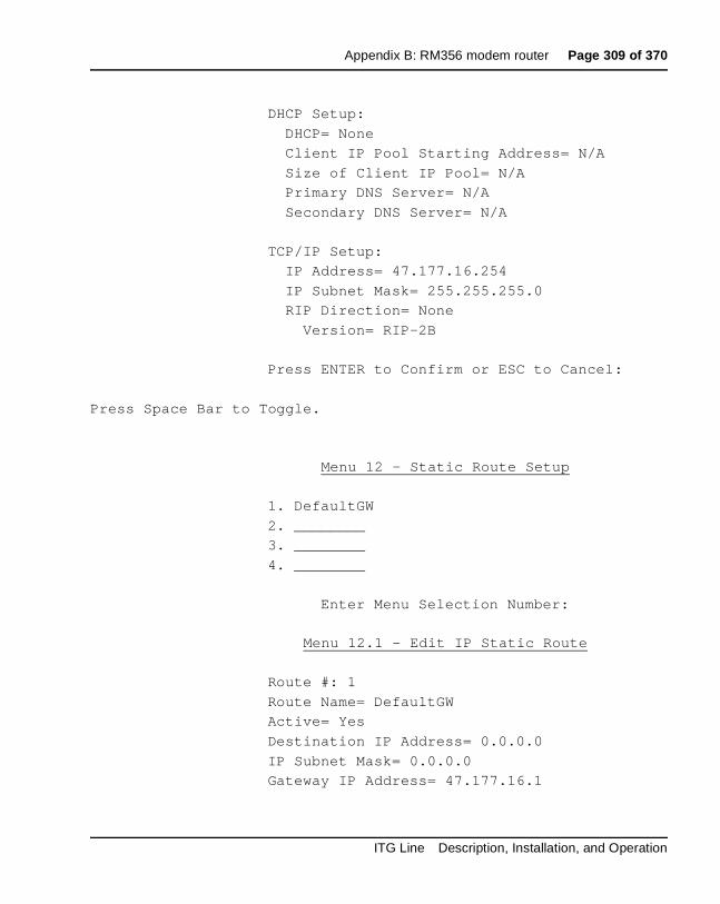
Appendix B: RM356 modem router Page 309 of 370
DHCP Setup:
DHCP= None
Client IP Pool Starting Address= N/A
Size of Client IP Pool= N/A
Primary DNS Server= N/A
Secondary DNS Server= N/A
TCP/IP Setup:
IP Address= 47.177.16.254
IP Subnet Mask= 255.255.255.0
RIP Direction= None
Version= RIP-2B
Press ENTER to Confirm or ESC to Cancel:
Press Space Bar to Toggle.
Menu 12 - Static Route Setup
1. DefaultGW
2. ________
3. ________
4. ________
Enter Menu Selection Number:
Menu 12.1 - Edit IP Static Route
Route #: 1
Route Name= DefaultGW
Active= Yes
Destination IP Address= 0.0.0.0
IP Subnet Mask= 0.0.0.0
Gateway IP Address= 47.177.16.1
ITG Line Description, Installation, and Operation
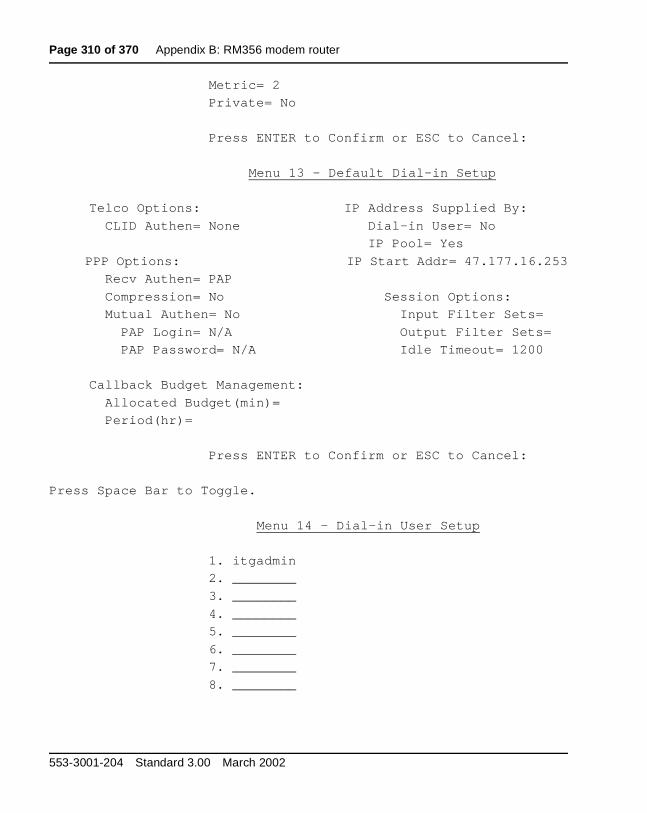
Page 310 of 370 Appendix B: RM356 modem router
Metric= 2
Private= No
Press ENTER to Confirm or ESC to Cancel:
Menu 13 - Default Dial-in Setup
Telco Options: IP Address Supplied By:
CLID Authen= None Dial-in User= No
IP Pool= Yes
PPP Options: IP Start Addr= 47.177.16.253
Recv Authen= PAP
Compression= No Session Options:
Mutual Authen= No Input Filter Sets=
PAP Login= N/A Output Filter Sets=
PAP Password= N/A Idle Timeout= 1200
Callback Budget Management:
Allocated Budget(min)=
Period(hr)=
Press ENTER to Confirm or ESC to Cancel:
Press Space Bar to Toggle.
Menu 14 - Dial-in User Setup
1. itgadmin
2. ________
3. ________
4. ________
5. ________
6. ________
7. ________
8. ________
553-3001-204 Standard 3.00 March 2002
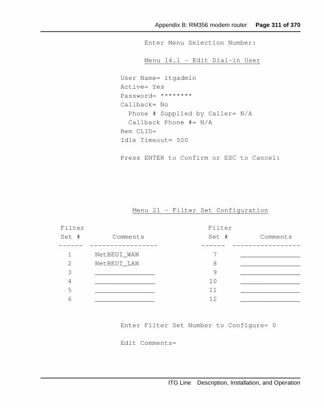
Appendix B: RM356 modem router Page 311 of 370
Enter Menu Selection Number:
Menu 14.1 - Edit Dial-in User
User Name= itgadmin
Active= Yes
Password= ********
Callback= No
Phone # Supplied by Caller= N/A
Callback Phone #= N/A
Rem CLID=
Idle Timeout= 500
Press ENTER to Confirm or ESC to Cancel:
Menu 21 - Filter Set Configuration
Filter Filter
Set # Comments Set # Comments
------ ----------------- ------ -----------------
1 NetBEUI_WAN 7 _______________
2 NetBEUI_LAN 8 _______________
3 _______________ 9 _______________
4 _______________ 10 _______________
5 _______________ 11 _______________
6 _______________ 12 _______________
Enter Filter Set Number to Configure= 0
Edit Comments=
ITG Line Description, Installation, and Operation

Page 312 of 370 Appendix B: RM356 modem router
Press ENTER to Confirm or ESC to Cancel:
Menu 21.1 - Filter Rules Summary
# A Type Filter Rules M m n
- - ---- ----------------------------------------------- - - -
1 Y IP Pr=17, SA=0.0.0.0, SP=137, DA=0.0.0.0 N D N
2 Y IP Pr=17, SA=0.0.0.0, SP=138, DA=0.0.0.0 N D N
3 Y IP Pr=17, SA=0.0.0.0, SP=139, DA=0.0.0.0 N D N
4 Y IP Pr=6, SA=0.0.0.0, SP=137, DA=0.0.0.0 N D N
5 Y IP Pr=6, SA=0.0.0.0, SP=138, DA=0.0.0.0 N D N
6 Y IP Pr=6, SA=0.0.0.0, SP=139, DA=0.0.0.0 N D F
Enter Filter Rule Number (1-6) to Configure:
Menu 23 - System Password
Old Password= ?
New Password= ?
Retype to confirm= ?
Enter here to CONFIRM or ESC to CANCEL:
Menu 24 - System Maintenance
1. System Status
2. Terminal Baud Rate
3. Log and Trace
4. Diagnostic
5. Backup Configuration
6. Restore Configuration
7. Software Update
8. Command Interpreter Mode
9. Call Control
Enter Menu Selection Number:
553-3001-204 Standard 3.00 March 2002

Appendix B: RM356 modem router Page 313 of 370
Menu 24.1 -- System Maintenance - Status
Port Status Speed TXPkts RXPkts Errs Tx B/s Rx B/s Up Time
1 Idle 0Kbps 16206 12790 0 0 0 0:00:00
Total Outcall Time: 0:00:00
Ethernet: Name: Room_304_RCH_Traini
Status: 10M/Half Duplex RAS S/W Version: V2.13 | 9/25/98
TX Pkts: 135579 Ethernet Address:00:a0:c5:e0:5b:a6
RX Pkts: 662866
Collisions: 49
LAN Packet Which Triggered Last Call:
Press Command:
COMMANDS: 1-Drop Port 1 9-Reset Counters ESC-Exit
Menu 24.2 -- System Maintenance - Change Terminal Baud Rate
Terminal Baud Rate: 9600
Press ENTER to Confirm or ESC to Cancel:
Press Space Bar to Toggle.
Menu 24.3 == System Maintenance - Log and Trace
1. View Error Log
2. Syslog and Accounting
Please enter selection:
0 179754 PINI INFO SMT Session End
1 179761 PP09 INFO Password pass
ITG Line Description, Installation, and Operation

Page 314 of 370 Appendix B: RM356 modem router
2 179761 PINI INFO SMT Session Begin
3 179763 PINI INFO SMT Session End
4 179772 PP09 INFO Password pass
5 179772 PINI INFO SMT Session Begin
6 179775 PINI INFO SMT Session End
7 179783 PP09 INFO Password pass
8 179783 PINI INFO SMT Session Begin
9 179788 PINI INFO SMT Session End
10 179796 PP09 INFO Password pass
11 179796 PINI INFO SMT Session Begin
12 179798 PINI INFO SMT Session End
13 179812 PP09 INFO Password pass
14 179812 PINI INFO SMT Session Begin
15 179815 PINI INFO SMT Session End
16 179830 PP09 INFO Password pass
17 179830 PINI INFO SMT Session Begin
18 179834 PINI INFO SMT Session End
Menu 24.3.2 -- System Maintenance - Syslog and Accounting
Syslog:
Active= No
Syslog IP Address= ?
Log Facility= Local 1
Press ENTER to Confirm or ESC to Cancel:
Press Space Bar to Toggle.
Menu 24.4 - System Maintenance - Diagnostic
MODEM System
1. Drop MODEM 21. Reboot System
2. Reset MODEM 22. Command Mode
3. Manual Call
553-3001-204 Standard 3.00 March 2002
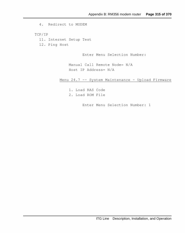
Appendix B: RM356 modem router Page 315 of 370
4. Redirect to MODEM
TCP/IP
11. Internet Setup Test
12. Ping Host
Enter Menu Selection Number:
Manual Call Remote Node= N/A
Host IP Address= N/A
Menu 24.7 -- System Maintenance - Upload Firmware
1. Load RAS Code
2. Load ROM File
Enter Menu Selection Number: 1
ITG Line Description, Installation, and Operation

Page 316 of 370 Appendix B: RM356 modem router
553-3001-204 Standard 3.00 March 2002

Page 317 of 370
322
Appendix C: Product integrityContents
This section contains information on the following topics:
Overview . . . . . . . . . . . . . . . . . . . . . . . . . . . . . . . . . . . . . . . . . . . . . . . . 317
Reliability . . . . . . . . . . . . . . . . . . . . . . . . . . . . . . . . . . . . . . . . . . . . . . . 317Mean time between failures (MTBF) . . . . . . . . . . . . . . . . . . . . . . . . 317ITG Line card power consumption . .. . . . . . . . . . . . . . . . . . . . . . . . 318
Environmental specifications . . . . . . . . . . . . . . . . . . . . . . . . . . . . . . . . 318Temperature-related conditions . . . . . . . . . . . . . . . . . . . . . . . . . . . . 319
Electrical regulatory standards . . . . . . . . . . . . . . . . . . . . . . . . . . . . . . . 320Safety . . . . . . . . . . . . . . . . . . . . . . . . . . . . . . . . . . . . . . . . . . . . . . . . 320Electro-magnetic compatibility (EMC) . . . . . . . . . . . . . . . . . . . . . . 320
OverviewThis chapter presents information about the Internet Telephony Gateway (ITG) Line card reliability, environmental specifications, and electrical regulatory standards.
ReliabilityReliability is measured by the Mean Time Between Failures (MTBF).
Mean time between failures (MTBF)The ITG Line card Mean Time Between Failure (MTBF) is 46 years. Failures
per 106 hours of operation are 2.483, based on 40 degrees C (140 degrees F).
ITG Line Description, Installation, and Operation

Page 318 of 370 Appendix C: Product integrity
ITG Line card power consumptionThe worst case current drawn by the ITG Line card from each Backplane voltage supply is:
+ 15 volt = 19.3 watts => 0.640 amps
+5 volt = 10.5 watts => 2.1 amps
Environmental specificationsTable 52 shows the environmental specifications of the ITG Line card. The ITG line card provides external interface protection to -52 V dc, but does not provide lightning or hazardous voltage protection.
Measurements of performance in regards to temperature and shock were made under test conditions as described in the following table.
Table 52ITG Line card—environmental specifications
Parameter Specifications
Operating temperature 0° to +60° C (+32 to +140° F), ambient
Operating humidity 5 to 95% RH (non-condensing)
Storage temperature –40° to +70° C (–40° to +158° F)
553-3001-204 Standard 3.00 March 2002

Appendix C: Product integrity Page 319 of 370
Temperature-related conditionsRefer to Table 53 for a display of acceptable temperature and humidity ranges for the ITG Line card.
Table 53ITG Line card environmental specifications
Specification Minimum Maximum
Normal Operation
Recommended 15° C 30° C
Relative humidity 20% 55% (non- condensing)
Absolute 10 ° C 45° C
Relative humidity 20% to 80% (non-condensing)
Short Term (less than 72 hr)
–40° C 70° C
Rate of change Less than 1° C for every 3 minutes
Storage
Recommended –20° C 60° C
Relative humidity 5% 95% (non-condensing)
–40° C to 70° C, non-condensing
Temperature Shock
In 3 minutes –40° C 25° C
In 3 minutes 70° C 25° C
-40° to 70° C, non-condensing
ITG Line Description, Installation, and Operation

Page 320 of 370 Appendix C: Product integrity
Electrical regulatory standardsThe following three tables list the safety and electro-magnetic compatibility regulatory standards for the ITG Line card, listed by geographic region. Specifications for the ITG Line card meet or exceed the standards listed in these regulations.
SafetyTable 54 provides a list of safety regulations met by the ITG Line card, along with the type of regulation and the country/region covered by each regulation.
Electro-magnetic compatibility (EMC)Electro-Magnetic Containment (EMC) compliance requirements depend on the regulations in effect for the country where the Meridian 1 and Succession CSE 1000 is located. CISPR 22 Class B defines more stringent EMC limits than CISPR 22 Class A requirements (that is, equipment that meets CISPR 22 Class B exceeds CISPR 22 Class A requirements and can be used globally).
The ITG Line card is approved for CISPR 22 Class A (and FCC Part 15 Class A) limits and approved to CISPR 22 Class B limits.
Table 54Safety regulations
Regulation Identifier Regulatory Agency
UL 1459 Safety, United States, CALA
CSA 22.2 225 Safety, Canada
EN 41003 Safety, International Telecom
EN 60950/IEC 950 Safety, International
BAKOM SR 784.103.12/4.1/1 EMC/Safety (Switzerland)
AS3260, TS001 - TS004, TS006 Safety/Network (Australia)
JATE Safety/Network (Japan)
553-3001-204 Standard 3.00 March 2002
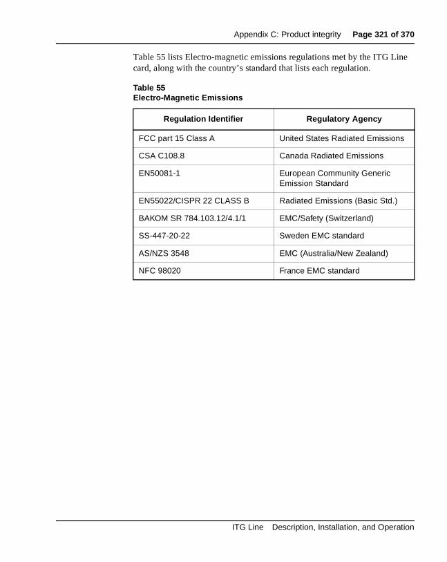
Appendix C: Product integrity Page 321 of 370
Table 55 lists Electro-magnetic emissions regulations met by the ITG Line card, along with the country’s standard that lists each regulation.
Table 55Electro-Magnetic Emissions
Regulation Identifier Regulatory Agency
FCC part 15 Class A United States Radiated Emissions
CSA C108.8 Canada Radiated Emissions
EN50081-1 European Community Generic Emission Standard
EN55022/CISPR 22 CLASS B Radiated Emissions (Basic Std.)
BAKOM SR 784.103.12/4.1/1 EMC/Safety (Switzerland)
SS-447-20-22 Sweden EMC standard
AS/NZS 3548 EMC (Australia/New Zealand)
NFC 98020 France EMC standard
ITG Line Description, Installation, and Operation

Page 322 of 370 Appendix C: Product integrity
Table 56 lists Electro-magnetic immunity regulations met by the ITG Line card, along with the country’s standard that lists each regulation.
Table 56Electro-Magnetic Immunity
Regulation Identifier Regulatory Agency
CISPR 22 Sec. 20 Class B I/O conducted noise
IEC 801-2 (level 4) ESD (Basic Standard)
IEC 801-3 (level 2) Radiated Immunity (Basic Standard)
IEC 801-4 (level 3) Fast transient/Burst Immunity (Basic Standard)
IEC 801-5 (level 4, preliminary) Surge Immunity (Basic Standard)
IEC 801-6 (preliminary) Conducted Disturbances (Basic Standard)
BAKOM SR 784.103.12/4.1/1 EMC/Safety (Switzerland)
SS-447-20-22 Sweden EMC standard
AS/NZS 3548 EMC (Australia/New Zealand)
NFC 98020 France EMC standard
553-3001-204 Standard 3.00 March 2002
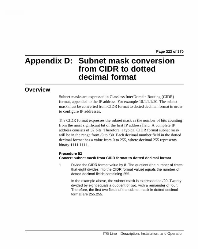
Page 323 of 370
324
Appendix D: Subnet mask conversion from CIDR to dotted decimal format
OverviewSubnet masks are expressed in Classless InterDomain Routing (CIDR) format, appended to the IP address. For example 10.1.1.1/20. The subnet mask must be converted from CIDR format to dotted decimal format in order to configure IP addresses.
The CIDR format expresses the subnet mask as the number of bits counting from the most significant bit of the first IP address field. A complete IP address consists of 32 bits. Therefore, a typical CIDR format subnet mask will be in the range from /9 to /30. Each decimal number field in the dotted decimal format has a value from 0 to 255, where decimal 255 represents binary 1111 1111.
Procedure 52Convert subnet mask from CIDR format to dotted decimal format
1 Divide the CIDR format value by 8. The quotient (the number of times that eight divides into the CIDR format value) equals the number of dotted decimal fields containing 255.
In the example above, the subnet mask is expressed as /20. Twenty divided by eight equals a quotient of two, with a remainder of four. Therefore, the first two fields of the subnet mask in dotted decimal format are 255.255.
ITG Line Description, Installation, and Operation

Page 324 of 370 Appendix D: Subnet mask conversion from CIDR to dotted decimal format
2 If there is a remainder, refer to Table 57, to obtain the dotted decimal value for the field following the last field containing “255”. In the example of /20 above, the remainder is four. In Table 57, a remainder of four equals a binary value of 1111 0000 and the dotted decimal value of the next and last field is 240. Therefore the first three fields of the subnet mask are 255.255.240.
3 If there are any remaining fields in the dotted decimal format, they have a value of 0. Therefore, the complete subnet mask in dotted decimal format is 255.255.240.0.
—————————— End of Procedure ——————————
Table 57CIDR format remainders
Remainder of CIDR format value divided by eight
Binary value Dotted decimal value
1 1000 0000 128
2 1100 0000 192
3 1110 0000 224
4 1111 0000 240
5 1111 1000 248
6 1111 1100 252
7 1111 1110 254
553-3001-204 Standard 3.00 March 2002
Page 325 of 370
334
Appendix E: DHCP Supplementary Information
ContentsThis section contains information on the following topics:
Introduction to DHCP . . . . . . . . . . . . . . . . . . . . . . . . . . . . . . . . . . . . . . 325
IP Acquisition Sequence . . . . . . . . . . . . . . . . . . . . . . . . . . . . . . . . . . . . 330
i2004 support for DHCP . . . . . . . . . . . . . . . . . . . . . . . . . . . . . . . . . . . . 334
Introduction to DHCPIn order to understand how the i2004 Internet Telephone acquires the needed network configuration parameters automatically, the following section briefly describes the Dynamic Host Configuration Protocol (DHCP). Read this section if you are unfamiliar with the DHCP. Topics discussed will be helpful for the configuration and future maintenance of the DHCP server and ensure correct implementation with the i2004 Internet Telephone.
DHCP is an extension of BootP. Like BootP, it operates on the client-server model. Unlike BootP, DHCP has more message types. DHCP allows the dynamic allocation of IP addresses to different clients. It can be used to configure clients by supplying the network configuration parameters such as gateway or router IP addresses.
ITG Line Description, Installation, and Operation
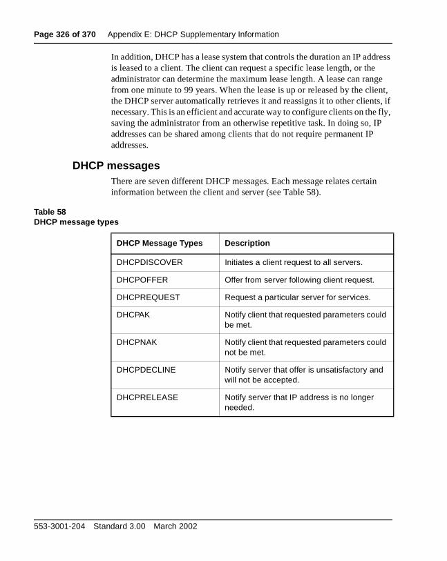
Page 326 of 370 Appendix E: DHCP Supplementary Information
In addition, DHCP has a lease system that controls the duration an IP address is leased to a client. The client can request a specific lease length, or the administrator can determine the maximum lease length. A lease can range from one minute to 99 years. When the lease is up or released by the client, the DHCP server automatically retrieves it and reassigns it to other clients, if necessary. This is an efficient and accurate way to configure clients on the fly, saving the administrator from an otherwise repetitive task. In doing so, IP addresses can be shared among clients that do not require permanent IP addresses.
DHCP messagesThere are seven different DHCP messages. Each message relates certain information between the client and server (see Table 58).
Table 58DHCP message types
DHCP Message Types Description
DHCPDISCOVER Initiates a client request to all servers.
DHCPOFFER Offer from server following client request.
DHCPREQUEST Request a particular server for services.
DHCPAK Notify client that requested parameters could be met.
DHCPNAK Notify client that requested parameters could not be met.
DHCPDECLINE Notify server that offer is unsatisfactory and will not be accepted.
DHCPRELEASE Notify server that IP address is no longer needed.
553-3001-204 Standard 3.00 March 2002
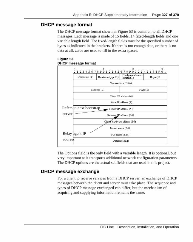
Appendix E: DHCP Supplementary Information Page 327 of 370
DHCP message formatThe DHCP message format shown in Figure 53 is common to all DHCP messages. Each message is made of 15 fields, 14 fixed-length fields and one variable length field. The fixed-length fields must be the specified number of bytes as indicated in the brackets. If there is not enough data, or there is no data at all, zeros are used to fill in the extra spaces.
Figure 53DHCP message format
The Options field is the only field with a variable length. It is optional, but very important as it transports additional network configuration parameters. The DHCP options are the actual subfields that are used in this project.
DHCP message exchangeFor a client to receive services from a DHCP server, an exchange of DHCP messages between the client and server must take place. The sequence and types of DHCP message exchanged can differ, but the mechanism of acquiring and supplying information remains the same.
Refers to next bootstrap
server
Relay agent IP
address
ITG Line Description, Installation, and Operation
Page 328 of 370 Appendix E: DHCP Supplementary Information
Usually the client initiates the exchange with a DHCP message broadcast. Using a broadcast allows the client to send messages to all the servers on the network without having an associated IP address. The broadcast is local to the LAN unless a DHCP relay agent is present to forward the packet.
At this point, the client has no information about the server or the IP address it is going to receive (unless it is requesting a renewal), so the fields in the DHCP message are empty. However, the client knows its own MAC address and includes it in the Client hardware address field. The client may also have a list of parameters it would like to acquire and can request them from the DHCP server by including the Parameter Request List option (Option Code 55) in the DHCPDISCOVER message.
When the DHCP server sees the broadcast, it responds by broadcasting its own DHCP message. The server, since it knows more about the network, is able to fill in most of the information in the message. For example, information such as server IP address and gateway IP address are included in their respective fields. Since the client does not have an IP address yet, the server uses the client's MAC address to uniquely identify it. When the client sees the broadcast, it matches its MAC address against the one in the message.
Using this method, the server and client can supply or receive information through the exchange of their DHCP messages.
DHCP optionsDHCP options are the sub-fields of the Options field. They carry additional network configuration information requested by the client such as IP address lease length and subnet mask.
Each DHCP option has an associated option code and a format for carrying data. Usually the format is as follows:
Option code Length Data
There are two categories of DHCP options, standard and non-standard. The standard options are predefined by the industry, while non-standard options are user-defined to fit the needs of a particular vendor or site.
553-3001-204 Standard 3.00 March 2002
Appendix E: DHCP Supplementary Information Page 329 of 370
There are a total of 255 DHCP option codes where option codes 0 and 255 are reserved, 1-77 are predefined, 1-254 can be used for Vendor Specific Options, and 128-254 are designated for Site Specific Options. This arrangement allows for future expansion and is used as a guideline for choosing option codes.
Vendor Specific/Encapsulated OptionThe Vendor Specific DHCP options are vendor-defined options for carrying vendor-related information. It is possible to override predefined standard options; however, doing so can cause conflict when used with components that follow the industry standard.
A useful option is the standard Vendor Encapsulated option - code 43. It is used to encapsulate other DHCP options as sub-options. For example, Nortel Network's i2004 Internet Telephone requires vendor specific Internet Telephony Gateway (ITG) Line card information. The vendor, Nortel Networks, decided to carry this information in one of several Site Specific options and then encapsulate it into option 43. Since the information is specific to a Nortel Networks product, it is vendor specific. Once encapsulated, the information appears as one or more sub-options inside option 43, which the i2004 Internet Telephone decodes.
Site Specific OptionAnother way to transport the ITG Line card information is through Site Specific options. These are unused DHCP options that have not been predefined to carry standard information. Unlike the Vendor Specific options, the information transported is "site" specific and option codes 128-254 are used for encoding.
For Nortel Network's i2004 Internet Telephone, the ITG Line card information involves the location of the ITG Line card in the network. This varies for different sites and can be implemented in a Site Specific option. If the Vendor Encapsulation option is used, the information will have to first be encoded in a Site Specific option. Nortel Networks has provided a list of five possible Site Specific option codes to implement the ITG Line card information. Only one of the five codes needs to be implemented to carry the information, but the choice is to offset the possibility that the option code chosen has been used for other purposes.
ITG Line Description, Installation, and Operation
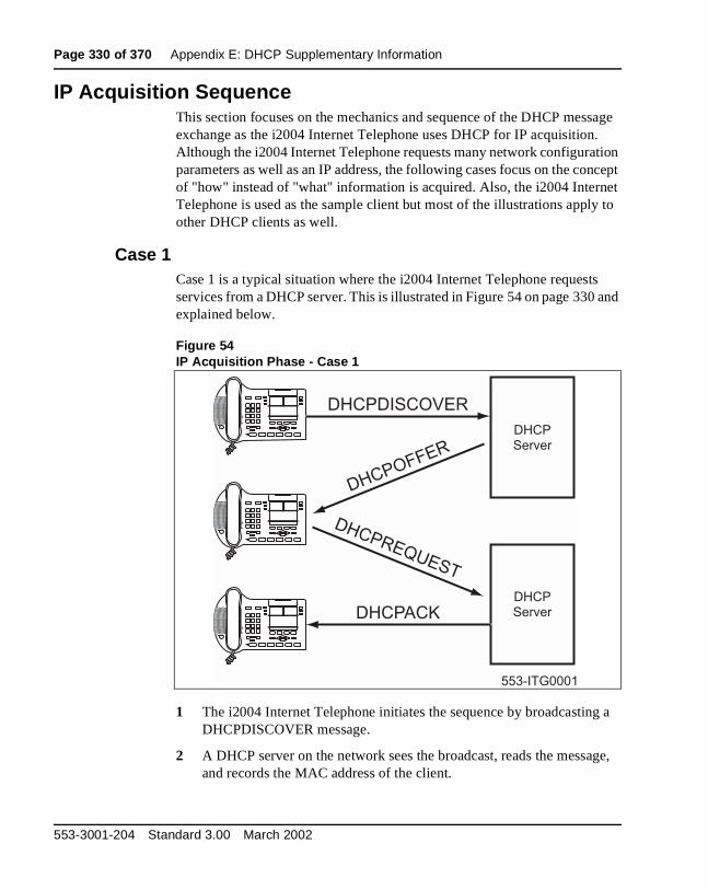
Page 330 of 370 Appendix E: DHCP Supplementary Information
IP Acquisition SequenceThis section focuses on the mechanics and sequence of the DHCP message exchange as the i2004 Internet Telephone uses DHCP for IP acquisition. Although the i2004 Internet Telephone requests many network configuration parameters as well as an IP address, the following cases focus on the concept of "how" instead of "what" information is acquired. Also, the i2004 Internet Telephone is used as the sample client but most of the illustrations apply to other DHCP clients as well.
Case 1Case 1 is a typical situation where the i2004 Internet Telephone requests services from a DHCP server. This is illustrated in Figure 54 on page 330 and explained below.
Figure 54IP Acquisition Phase - Case 1
1 The i2004 Internet Telephone initiates the sequence by broadcasting a DHCPDISCOVER message.
2 A DHCP server on the network sees the broadcast, reads the message, and records the MAC address of the client.
DHCP
Server
DHCP
Server
DHCPDISCOVER
DHCPREQUEST
DHCPOFFER
DHCPACK
553-ITG0001
553-3001-204 Standard 3.00 March 2002

Appendix E: DHCP Supplementary Information Page 331 of 370
3 It checks its own IP address pool(s) for an available IP address and broadcasts a DHCPOFFER message if one is available. Usually the server ARPs or PINGs the IP address to make sure it is not being used.
4 The i2004 Internet Telephone sees the broadcast and after matching its MAC address with the offer, reads the rest of the message to find out what else is being offered.
5 If the offer is acceptable, it sends out a DHCPREQUEST message with the DHCP server's IP address in the Server IP address field.
6 The DCHP server will match the IP address in the Server IP address field against its own to find out who the packet belongs to.
7 If the IPs match and there is no problem supplying the requested information, it assigns the IP address to the client by sending a DHCPACK.
8 If the final offer is not rejected, the IP acquisition sequence is complete.
Case 2The IP acquisition becomes unsuccessful if either the server or the client decides not to participate.
If the DHCP server cannot supply the requested information:
• It sends a DHCPNAK message and no IP address is assigned to the client. This can happen if the requested IP address has already been assigned to a different client (see Figure 55 on page 332).
If the Client decides to reject the final offer (after the server sends a DHCPACK message):
• the Client sends a DHCPDECLINE message to the server, telling it the offer is rejected.
• the Client will have to restart the IP acquisition by sending another DHCPDISCOVER message, in search of another offer.
ITG Line Description, Installation, and Operation

Page 332 of 370 Appendix E: DHCP Supplementary Information
Figure 55IP Acquisition Sequence - Case 2
Case 3Finally, when a client is finished with a particular IP address, it sends a DHCPRELEASE message to the server which reclaims the IP address. If the client requires the same IP address again, it can initiate the process as follows:
1 i2004 Internet Telephone broadcasts a DHCPREQUEST to a particular DHCP server by including the server's IP address in the Server IP Address field of the message. Since it knows which IP address it wants, it requests it in the DHCP message.
2 The DHCP server sends a DHCPACK message if all the parameters requested are met.
Case 1 is similar to Case 3, except the first two messages have been eliminated. This reduces the amount of traffic produced on the network (see Figure 56 on page 333).
DHCP
Server
DHCP
Server
DHCPDISCOVER
DHCPREQUEST
DHCPOFFER
DHCPNAK
DHCPDISCOVER
DHCPREQUEST
DHCPOFFER
DHCPACK
553-ITG0002
Internet Telephone 1 Internet Telephone 2
i2004 i2004
553-3001-204 Standard 3.00 March 2002

Appendix E: DHCP Supplementary Information Page 333 of 370
Figure 56IP Acquisition sequence - Case 3
Multiple DHCPOFFERSIn some networks, if more than one DHCP server is present, a client can receive multiple DHCPOFFER messages. Under these situations, the IP acquisition sequence depends on the client. The client can wait for multiple offers, or just go with the first offer it receives. If it accepts multiple offers, it compares them before choosing one with the most fitting configuration parameters. When a decision is made, the message exchange is the same as if there is only one DHCP server and proceeds as in the previous Cases. The servers that have not been chosen to provide the service do not participate in the exchange.
The i2004 Internet Telephone only responds to DHCPOFFERs that have the same unique string identifier, "Nortel-i2004-A", as the i2004 Internet Telephone. This string must appear in the beginning of the list of ITG Line card parameters. Without this string, the i2004 Internet Telephone does not accept the DHPCOFFER, even if all parameters requested and ITG Line card information are present. If no valid DHCPOFFERs are sent then, the i2004 Internet Telephone keeps broadcasting in search of a valid offer.
With multiple DHCP servers on the same network, a problem can occur if any two of the servers have overlapping IP address range and no redundancy. DHCP redundancy is a property of DHCP servers, which allows different DHCP servers to serve the same IP address ranges simultaneously. Administrators must be aware that not all DHCP servers have this capability.
DHCP
Server
DHCPREQUEST
DHCPACK
553-ITG0003
i2004 Internet Telephone
ITG Line Description, Installation, and Operation

Page 334 of 370 Appendix E: DHCP Supplementary Information
i2004 support for DHCPDHCP support in the i2004 Internet Telephone includes sending a Class Identifier option with the value "Nortel-i2004-A" in each DHCP Discovery and Request. Additionally, the i2004 checks for either a Vendor Specific option message with a specific, unique to Nortel i2004, encapsulated sub-type, or a Site Specific DHCP option. In either case, an i2004 Internet Telephone specific option must be returned by the i2004-aware DHCP server in all DHCPOFFER and DHCPACK messages. The i2004 Internet Telephone uses the information returned in this option to configure itself for proper operation. This includes binding a new IP address, netmask, and default gateway (for local IP stack) as well as configuring the primary bootstrap server and optional secondary server.
553-3001-204 Standard 3.00 March 2002

Page 335 of 370
358
Appendix F: Setup and Configuration of DHCP Servers
ContentsThis section contains information on the following topics:
Installing a Windows NT 4 server . .. . . . . . . . . . . . . . . . . . . . . . . . . . . 336
Configuring a Windows NT 4 server with DHCP . . . . . . . . . . . . . . . . 336
Installing ISC’s DHCP Server . .. . . . . . . . . . . . . . . . . . . . . . . . . . . . . . 342
Configuring ISC’s DHCP Server . . . . . . . . . . . . . . . . . . . . . . . . . . . . . 342Configuring ISC’s DHCP to work with the i2004 telephone . .. . . . 342Example 1: Configuration file . . . . . . . . . . . . . . . . . . . . . . . . . . . . . 345
Installing and configuring a Solaris 2 server . .. . . . . . . . . . . . . . . . . . . 348Installing a Solaris 2 Server . . . . . . . . . . . . . . . . . . . . . . . . . . . . . . . 348Configuring a Solaris 2 server . . . . . . . . . . . . . . . . . . . . . . . . . . . . . 348
Format of ITG Line Card Information . . . . . . . . . . . . . . . . . . . . . . . . . 350DHCP Support for i2004 . . . . . . . . . . . . . . . . . . . . . . . . . . . . . . . . . 350Format for Nortel Networks i2004 Terminal DHCP Class Identifier Field . . . . . . . . . . . . . . . . . . . . . . . . . . . . . . . . . . . . 352Format for Nortel Networks i2004 Terminal DHCP Encapsulated Vendor Specific Field . . . . . . . . . . . . . . . . . . . . . . . . 352Format for Nortel Networks i2004 Terminal DHCP Site Specific Option . . . . . . . . . . . . . . . . . . . . . . . . . . . . . . . . . . . . . 355
ITG Line Description, Installation, and Operation

Page 336 of 370 Appendix F: Setup and Configuration of DHCP Servers
Installing a Windows NT 4 serverTo set-up the Windows NT 4 server, follow the instructions provided in the installation booklet. After completion, install Service Pack 3 and make sure the DHCP Manager is included.
Configuring a Windows NT 4 server with DHCPConfigure a Windows NT 4 server with DHCP services using the GUI provided.
Procedure 53Launching the DHCP Manager
1 Click on the Windows Start button. Select Programs | Administrative tools (Common) | DHCP Manager (see Figure 57 on page 337). The DHCP Manager window opens.
2 Double-click Local Machines in the left pane. The Create Scope - (Local) window opens (see Figure 58 on page 338).
3 Create and then fill in the information. Click OK when finished.
4 In the DHCP Manager - (Local) window, highlight the scope that will serve the i2004 clients.
5 From the DHCP Options menu, select Default Values. The DHCP Options - Default Values window opens.
6 Click the New button (see Figure 59 on page 339). The Change Option Type window opens.
7 Fill in the information and click OK when finished. Click OK again.
8 From the DHCP Manager - (Local) window, highlight the scope to which you want to add DHCP options.
9 From the DHCP Options menu, select Scope.The DHCP Options Scope window opens.
10 Chose standard DHCP options from the left panel and click the Add -> button to add them to the right panel. (see Figure 60 on page 340).
WARNINGIf you are installing a Windows NT 4 server with Service Pack 4 or later, follow the installation instructions included with your server hardware.
553-3001-204 Standard 3.00 March 2002
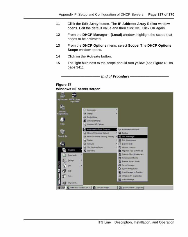
Appendix F: Setup and Configuration of DHCP Servers Page 337 of 370
11 Click the Edit Array button. The IP Address Array Editor window opens. Edit the default value and then click OK. Click OK again.
12 From the DHCP Manager - (Local) window, highlight the scope that needs to be activated.
13 From the DHCP Options menu, select Scope. The DHCP Options Scope window opens.
14 Click on the Activate button.
15 The light bulb next to the scope should turn yellow (see Figure 61 on page 341).
—————————— End of Procedure ——————————
Figure 57Windows NT server screen
ITG Line Description, Installation, and Operation

Page 338 of 370 Appendix F: Setup and Configuration of DHCP Servers
Figure 58Defining a new scope
553-3001-204 Standard 3.00 March 2002

Appendix F: Setup and Configuration of DHCP Servers Page 339 of 370
Figure 59Defining the Nortel-specific option
ITG Line Description, Installation, and Operation
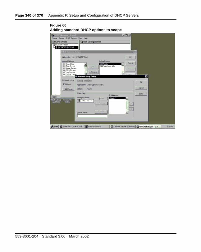
Page 340 of 370 Appendix F: Setup and Configuration of DHCP Servers
Figure 60Adding standard DHCP options to scope
553-3001-204 Standard 3.00 March 2002
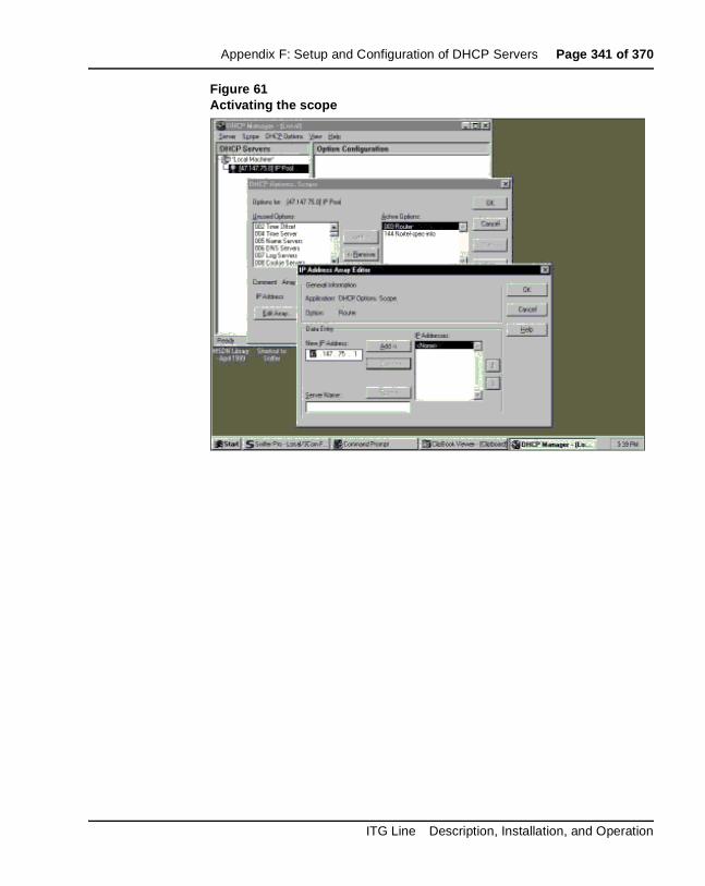
Appendix F: Setup and Configuration of DHCP Servers Page 341 of 370
Figure 61Activating the scope
ITG Line Description, Installation, and Operation
Page 342 of 370 Appendix F: Setup and Configuration of DHCP Servers
Installing ISC’s DHCP ServerTo set up ISC’s DHCP server, read the README file and follow the instructions on how to compile, make, and build the server. Once setup is complete, configure the server by following the description in the next section.
Configuring ISC’s DHCP ServerTo configure ISC’s DHCP server, a text based configuration process is used. Configuration is done by adding definitions and declarations in the dhcpd.conf file located at /etc/. Various “man” files are provided on how to configure the server, configure the lease system, use options and conditions, and run the server. Obtain the dhcpd.conf.man5 file in the server directory and read it carefully. It provides explanations on relevant topics as well as the location of other man files to read for additional information.
Configuring ISC’s DHCP to work with the i2004 telephoneUse Procedure 54 on page 343 to configure the ISC’s DHCP to work with the i2004 Internet Telephone.
There is a particular format for encoding the ITG Line card information. In addition to the configuration statements provided, other network and subnet declarations must also be included in the configuration file.
CAUTIONAlthough, Windows NT 4 also has the Vendor Encapsulation Option (option code 43), do not use it to encode the Internet Telephony Gateway (ITG) Line card information needed by the i2004. Windows NT 4 only allows 16 bytes of data to be encapsulated which is not enough to encode all the information needed.
Window NT 4’s DHCP server will transmit any user-defined option associated within a scope if the client requests it. It does not have the ability to distinguish among different types of clients, hence it cannot make decisions based on this information. This makes it impossible to create client specific IP address pool/scope.
553-3001-204 Standard 3.00 March 2002

Appendix F: Setup and Configuration of DHCP Servers Page 343 of 370
As mentioned in the beginning of this section, read the man files and use “Example 1: Configuration file” on page 345 on to configure ISC’s DHCP server to work with the i2004 Internet Telephone. Also, a copy of the configuration file used for this project is provided at the end of this section.
Procedure 54Configuring ISC’s DHCP server
1 Configure the server to identify a client correctly as the i2004 Internet Telephone. This is done using a match statement with a conditional if enclosed inside a class declaration, as follows:
class "i2004-clients"{
match if option vendor-class-identifier = 4e:6f:72:74:65:6c:2d:69:32:30:30:34:2d:41:00;}
The Hex string represents the text string “Nortel-i2004-A”. If the vendor-class-identifier obtained from the client’s DHCPDISCOVER message match this Hex-encoded string, then the server adds this client to the “i2004-clients” class. Once a client is classified as a member of a class it must follow the rules of the class.
2 Declare a pool of IP addresses exclusively for the members of the “i2004-clients” class. The pool declaration is used to group a range of IP addresses together with options and parameters that apply only to the pool.
ITG Line Description, Installation, and Operation

Page 344 of 370 Appendix F: Setup and Configuration of DHCP Servers
3 Restrict access to the pool. Use the allow or deny statement to include or exclude the members of a particular class. For example, the follow configuration code allows only members of “i2004-clients” to use this IP address pool:
pool{
allow members of "i2004-clients";
range 47.147.75.60 47.147.75.65;
option routers 47.147.75.1;
# Nortel Networks special string
option vendor-encapsulated-options 80:3d:4e:6f:72:…;}
Note: If a client is not a member of this class, it will not be assigned an IP address from this pool even if there were no other available IP addresses.
4 The DHCPOFFER from the ISC server must include the ITG Line card information if the client is an i2004 Internet Telephone. There are two methods to encode the necessary information for the i2004 client:
a. Use the vendor-encapsulated-options option (as in the previous example) to encode the information as a sub option.
b. Define a Site Specific option to carry the necessary information. To define a site specific option:
• give a declaration in the form of the name of the option, the option code, and the type of data it carries outside any pool or network declarations. For example:
option nortel-specific-info code 144 = string;
• replace the vendor-encapsulated option inside the pool statement with the definition,
option nortel-specific-info = “Nortel …”;
—————————— End of Procedure ——————————
553-3001-204 Standard 3.00 March 2002
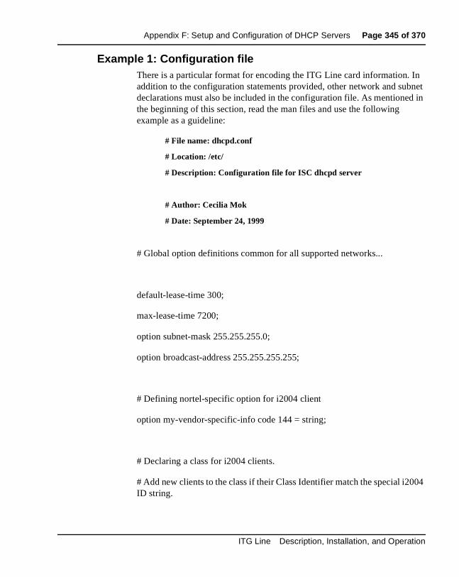
Appendix F: Setup and Configuration of DHCP Servers Page 345 of 370
Example 1: Configuration fileThere is a particular format for encoding the ITG Line card information. In addition to the configuration statements provided, other network and subnet declarations must also be included in the configuration file. As mentioned in the beginning of this section, read the man files and use the following example as a guideline:
# File name: dhcpd.conf
# Location: /etc/
# Description: Configuration file for ISC dhcpd server
# Author: Cecilia Mok
# Date: September 24, 1999
# Global option definitions common for all supported networks...
default-lease-time 300;
max-lease-time 7200;
option subnet-mask 255.255.255.0;
option broadcast-address 255.255.255.255;
# Defining nortel-specific option for i2004 client
option my-vendor-specific-info code 144 = string;
# Declaring a class for i2004 clients.
# Add new clients to the class if their Class Identifier match the special i2004 ID string.
ITG Line Description, Installation, and Operation

Page 346 of 370 Appendix F: Setup and Configuration of DHCP Servers
class "i2004-clients"
{
match if option vendor-class-identifier = 4e:6f:72:74:65:6c:2d:69:32:30:30:34:2d:41:00;
}
# Declaring another class for PC clients
class "pc-clients"
{}
# Declaring a shared network
# This is to accommodate two different subnets on the same
# physical network; see dhcpd.conf.man5 for more details
shared-network "myNetwork"
{
# Declaring subnet for current server
subnet 47.147.77.0 netmask 255.255.255.0
{}
# Declaring subnet for DHCP clients
subnet 47.147.75.0 netmask 255.255.255.0
553-3001-204 Standard 3.00 March 2002

Appendix F: Setup and Configuration of DHCP Servers Page 347 of 370
{
# Pool addresses for i2004 clients
pool
{
allow members of "i2004-clients";
range 47.147.75.60 47.147.75.65;
option routers 47.147.75.1;
# Nortel Networks special string
option nortel-specific-info = “Nortel…”;
}
default-lease-time 180;
max-lease-time 300;
}
}
Finally, before starting the server, create a blank dhcpd.leases file in the /etc/ directory, which is the same location as the dhcpd.conf file. Then to start the server, go to /var/usr/sbin/ and type:
./dhcpd
To run in debug mode, type:
./dhcpd –d –f
ITG Line Description, Installation, and Operation

Page 348 of 370 Appendix F: Setup and Configuration of DHCP Servers
Installing and configuring a Solaris 2 serverInstalling a Solaris 2 Server
To set up the Solaris 2 server, consult the accompanying manual and online documentation.
Configuring a Solaris 2 serverUse Procedure 55 on page 348 to configure Solaris 2 with DHCP.
Procedure 55Configuring a Solaris 2 server
1 Read the man pages listed below:
• dhcpconfig
• dhcptab
• in.dhcpd
Note: There are directions at the end of each page referring to other sources that may be helpful.
2 Collect information about the network such as subnet mask, router/gateway and DNS server IP addresses as specified. Make sure this information is current.
3 Log on as root and invoke the interface by typing dhcpconfig at the prompt. A list of questions will be presented and the administrator must supply answers, which are then used to configure the DHCP server.
Note: Solaris 2 uses a text-based interface for configuring DHCP services.
—————————— End of Procedure ——————————
553-3001-204 Standard 3.00 March 2002
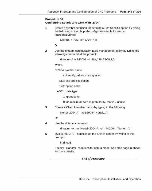
Appendix F: Setup and Configuration of DHCP Servers Page 349 of 370
Procedure 56Configuring Solaris 2 to work with i2004
1 Create a symbol definition for defining a Site Specific option by typing the following in the dhcptab configuration table located at /etc/default/dhcp:
NI2004 s Site,128,ASCII,1,0
Or
2 Use the dhtadm configuration table management utility by typing the following command at the prompt:
dhtadm -A -s NI2004 –d 'Site,128,ASCII,1,0'
where,
NI2004: symbol name
s: identify definition as symbol
Site: site specific option
128: option code
ASCII: data type
1: granularity
0: no maximum size of granularity, that is , infinite
3 Create a Client Identifier macro by typing in the following:
Nortel-i2004-A m:NI2004="Nortel…":
Or
4 Use the dhtadm command:
dhtadm -A -m Nortel-i2004-A -d ‘:NI2004=”Nortel…”:’
5 Invoke the DHCP services on the Solaris server by typing at the prompt.:
in.dhcpd,
Specify –d and/or –v options for debug mode. See man page in.dhpcd for more details.
—————————— End of Procedure ——————————
ITG Line Description, Installation, and Operation
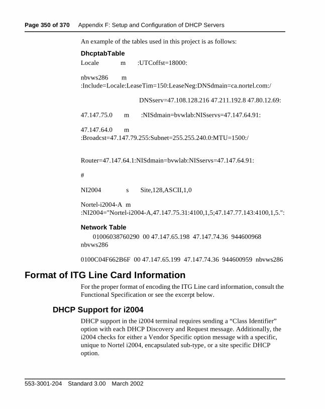
Page 350 of 370 Appendix F: Setup and Configuration of DHCP Servers
An example of the tables used in this project is as follows:
DhcptabTableLocale m :UTCoffst=18000:
nbvws286 m :Include=Locale:LeaseTim=150:LeaseNeg:DNSdmain=ca.nortel.com:/
DNSserv=47.108.128.216 47.211.192.8 47.80.12.69:
47.147.75.0 m :NISdmain=bvwlab:NISservs=47.147.64.91:
47.147.64.0 m :Broadcst=47.147.79.255:Subnet=255.255.240.0:MTU=1500:/
Router=47.147.64.1:NISdmain=bvwlab:NISservs=47.147.64.91:
#
NI2004 s Site,128,ASCII,1,0
Nortel-i2004-A m :NI2004="Nortel-i2004-A,47.147.75.31:4100,1,5;47.147.77.143:4100,1,5.":
Network Table01006038760290 00 47.147.65.198 47.147.74.36 944600968
nbvws286
0100C04F662B6F 00 47.147.65.199 47.147.74.36 944600959 nbvws286
Format of ITG Line Card InformationFor the proper format of encoding the ITG Line card information, consult the Functional Specification or see the excerpt below.
DHCP Support for i2004DHCP support in the i2004 terminal requires sending a “Class Identifier” option with each DHCP Discovery and Request message. Additionally, the i2004 checks for either a Vendor Specific option message with a specific, unique to Nortel i2004, encapsulated sub-type, or a site specific DHCP option.
553-3001-204 Standard 3.00 March 2002

Appendix F: Setup and Configuration of DHCP Servers Page 351 of 370
In either case, a Nortel i2004 specific option must be returned by the i2004 aware DHCP server in all Offer and Acknowledgement (Ack) messages. The i2004 will use the information returned in this option to configure itself for proper operation. This includes binding a new IP address, netmask, and gateway (for local IP stack) as well as configuring Server 1 (minimum) and optionally Server 2. By default, Server 1 is always assumed to be the "primary" server after a DHCP session.
In order for the i2004 to accept Offers/Acks they must contain the following:
• A Router option (i2004 needs a default router to function) AND
• A Subnet Mask option AND
• EITHER a Vendor Specific option as specified below OR a site specific option as specified below.
Note 1: The initial DHCP implementation required only the Vendor Specific encapsulated sub-option. In inter-op testing with Windows NT (up to Service Release 4); however, it was discovered that Windows NT does not properly adhere to RFC 1541. As a result it is not possible to use this option. The implementation was changed to add support for either Vendor Specific sub-ops or Site Specific options. This new extension has been tested and verified to work with Windows NT.
Note 2: The site-specific options are all DHCP options between 128 (0x80) and 254 (0xFE). These options are reserved for site specific use by the DHCP RFCs.
ITG Line Description, Installation, and Operation

Page 352 of 370 Appendix F: Setup and Configuration of DHCP Servers
Format for Nortel Networks i2004 Terminal DHCP Class Identifier Field
All i2004 terminals fill in the Class ID field of the DHCP Discovery and Request messages with:
"Nortel-i2004-A", where:
• ASCII encoded, NULL (0x00) terminated
• unique to Nortel i2004
• "-A" uniquely identifies this version.
Format for Nortel Networks i2004 Terminal DHCP Encapsulated Vendor Specific Field
This sub-option must be encapsulated in a DHCP Vendor Specific Option (Refer to RFC 1541 and RFC 1533) and returned by the DHCP server as part of each DHCP OFFER and ACK message in order for the i2004 to accept these messages as valid.
The i2004 will pull the relevant information out of this option and use it to configure the IP address for the primary and (optionally) secondary TPS's.
Note 1: Either this encapsulated sub-option must be present, or a similarly encoded site-specific option must be sent (see below), that is, configure the DHCP server to send one or the other - not both.
Note 2: The choice of using either Vendor Specific or Site Specific options is provided to allow Windows NT DHCP servers to be used with the i2004 (Windows NT servers do not properly implement the Vendor Specific Option and as a result, Windows NT implementations must use the Site Specific version).
553-3001-204 Standard 3.00 March 2002

Appendix F: Setup and Configuration of DHCP Servers Page 353 of 370
Format of the Encapsulated Vendor Specific Sub-option field
• Type (1 octet): 5 choices: 0x80, 0x90, 0x9d, 0xbf, 0xfb (128, 144, 157, 191, 251). Providing a choice of five types allows the i2004 to work in environments where the initial choice may already be in use by a different vendor. Pick only one TYPE byte.
• Length (1 octet): variable - depends on message content.
• Data (length octets): ASCII based with the following format:
"Nortel-i2004 -A,iii.jjj.kkk.lll:ppppp,aaa,rrr;iii.jjj.kkk.lll:pppp,aaa,rrr." where:
Note 1: "aaa" and "rrr" are ASCII encoded decimal numbers with a range of 0..255. They identify the "Action Code" and "Retry Count", respectively, for the associated TPS server. Internally to i2004 they will be stored as 1 octet (0x00..0xFF). Note that these fields must be no more than 3 digits long.
Note 2: The first server is always considered "Primary"; second server always considered "Secondary".
Parameter Description
Nortel-i2004-A Uniquely identifies this as the Nortel option
-A Signifies this version of this specification. Future enhancements could use -B
iii.jjj.kkk.lll:ppppp Identifies IP:port for server (ASCII encoded decimal)
aaa Identifies Action for server (ASCII encoded decimal, range 0..255)
rrr Identifies retry count for server (ASCII encoded decimal, range 0..255). This string may be NULL terminated although the NULL is not required for parsing.
ACSII symbols The comma "," is used to separate fields
The semicolon ";" is used to separate Primary from Secondary server information
The period "." is used to signal end of structure
ITG Line Description, Installation, and Operation

Page 354 of 370 Appendix F: Setup and Configuration of DHCP Servers
Note 3: If only one server is required, terminate primary TPS sequence immediately with "." instead of ";". For example, "Nortel-i2004-A,iii.jjj.kkk.lll:ppppp,aaa,rrr."
Note 4: Valid options are one server or two servers (0, 3... not allowed).
Note 5: Action code values:0 - reserved1 - UNIStim Hello (currently only this type is a valid choice)2..254 - reserved255 - reserved
Note 6: iii,jjj,kkk,lll are ASCII encoded, decimal numbers representing the IP address of the server. They do not need to be 3 digits long as the “.” and “:” delimiters will guarantee parsing. For example, '001', '01', and '1' would all be parsed correctly and interpreted as value 0x01 internal to the i2004. Note that these fields must be no more than three digits long each.
Note 7: ppppp is the port number in ASCII encoded decimal. It does not need to be five digits long as the “:” and “,” delimiters will guarantee parsing. For example, '05001', '5001', '1', '00001' would all be parsed correctly and accepted as correct. The valid range is 0 to 65535 which is stored internally in the i2004 as hexadecimal in range 0..0xFFFF. Note that this field must be no more than five digits long.
Note 8: In all cases, the ASCII encoded numbers are treated as decimal values and all leading zeros are ignored. More specifically, a leading zero does not change the interpretation of the value to be OCTAL encoded. For example, 0021, 021, and 21 are all parsed and interpreted as decimal 21.
553-3001-204 Standard 3.00 March 2002

Appendix F: Setup and Configuration of DHCP Servers Page 355 of 370
Format for Nortel Networks i2004 Terminal DHCP Site Specific Option
This option uses the "reserved for site specific use" DHCP options (number 128 to 254 - Refer to RFC 1541 and RFC 1533) and must be returned by the DHCP server as part of each DHCP OFFER and ACK message for the i2004 to accept these messages as valid.
The i2004 pulls the relevant information out of this option and uses it to configure the IP address and so on for the primary and (optionally) secondary TPS's.
Note 1: Either this site specific option must be present or a similarly encoded vendor-specific option must be sent (as described above). For example, configure the DHCP server to send one or the other - not both.
Note 2: The choice of using either Vendor Specific or Site Specific options is provided to allow Windows NT DHCP servers to be used with the i2004 (Windows NT servers do not properly implement the Vendor Specific Option and as a result, Windows NT implementations must use the Site Specific version).
Format of the DHCP Site Specific field
• Type (1 octet): five choices 0x80, 0x90, 0x9d, 0xbf, 0xfb (128, 144, 157, 191, 251). Providing a choice of five types allows the i2004 to work in environments where the initial choice may already be in use by a different vendor. Pick only one TYPE byte.
• Length (1 octet): variable - depends on message content.
• Data (length octets): ASCII based format:
"Nortel-i2004-A,iii.jjj.kkk.lll:ppppp,aaa,rrr;iii.jjj.kkk.lll:pppp,aaa,rrr."where:
ITG Line Description, Installation, and Operation

Page 356 of 370 Appendix F: Setup and Configuration of DHCP Servers
Note 1: "aaa" and "rrr" are ASCII encoded decimal numbers with a range of 0..255. They identify the "Action Code" and "Retry Count", respectively, for the associated TPS server. Internally to i2004 they will be stored as 1 octet (0x00..0xFF). Note that these fields must be no more than three digits long.
Note 2: The first server is always considered "Primary", and the second server is always considered "Secondary".
Note 3: If only one server is required, terminate the primary TPS sequence immediately with "." instead of ";". For example: "Nortel-i2004-A,iii.jjj.kkk.lll:ppppp,aaa,rrr."
Note 4: Valid options are one server or two servers (0, 3... are not allowed).
Parameter Description
Nortel-i2004-A Uniquely identifies this as the Nortel option
-A Signifies this version of this specification. Future enhancements could use -B
iii.jjj.kkk.lll:ppppp Identifies IP:port for server (ASCII encoded decimal)
aaa Identifies Action for server (ASCII encoded decimal, range 0..255)
rrr Identifies retry count for server (ASCII encoded decimal, range 0..255). This string may be NULL terminated although the NULL is not required for parsing.
ACSII symbols The comma "," is used to separate fields
The semicolon ";" is used to separate Primary from Secondary server information
The period "." is used to signal end of structure
553-3001-204 Standard 3.00 March 2002
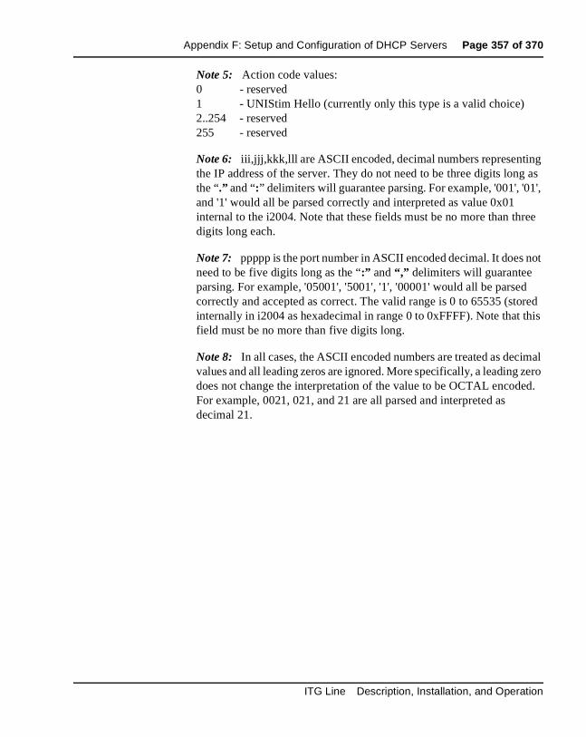
Appendix F: Setup and Configuration of DHCP Servers Page 357 of 370
Note 5: Action code values:0 - reserved1 - UNIStim Hello (currently only this type is a valid choice)2..254 - reserved255 - reserved
Note 6: iii,jjj,kkk,lll are ASCII encoded, decimal numbers representing the IP address of the server. They do not need to be three digits long as the “.” and “:” delimiters will guarantee parsing. For example, '001', '01', and '1' would all be parsed correctly and interpreted as value 0x01 internal to the i2004. Note that these fields must be no more than three digits long each.
Note 7: ppppp is the port number in ASCII encoded decimal. It does not need to be five digits long as the “:” and “,” delimiters will guarantee parsing. For example, '05001', '5001', '1', '00001' would all be parsed correctly and accepted as correct. The valid range is 0 to 65535 (stored internally in i2004 as hexadecimal in range 0 to 0xFFFF). Note that this field must be no more than five digits long.
Note 8: In all cases, the ASCII encoded numbers are treated as decimal values and all leading zeros are ignored. More specifically, a leading zero does not change the interpretation of the value to be OCTAL encoded. For example, 0021, 021, and 21 are all parsed and interpreted as decimal 21.
ITG Line Description, Installation, and Operation

Page 358 of 370 Appendix F: Setup and Configuration of DHCP Servers
553-3001-204 Standard 3.00 March 2002

Page 359 of 370
368
List of termsActive Leader
The Leader that at a given instant of time is performing the Leader role of being the designated point of contact in the group of Follower cards for all the Meridian 1 and Succession CSE 1000 systems in the network. The active leader card also provides endpoint management including registration/unregistration, authentication, address resolution (DN to IP and endpoint to gateway), and maintaining a list of endpoints currently active on the network.
AckAcknowledge message.
BackboneA network’s major transmission path, handling high-volume, high-density traffic.
BandwidthA measure of information carrying capacity available for a transmission medium, expressed in bits per second. The greater the bandwidth, the more information that can be sent in a given amount of time.
BBBest Bandwidth.
BHCABusy Hour Call Attempts.
ITG Line Description, Installation, and Operation
Page 360 of 370 List of terms
BootPBootstrap Protocol. Protocol used for communication between ITG Line cards. A protocol that allows network hosted systems to determine their IP address and other operational information using a simple datagram exchange with a central server.
BQBest Quality.
BridgeLAN equipment providing interconnection between two networks using the same addressing structure. A bridge filters out packets that stay on one LAN and forwards packets intended for other LANs.
CD-ROMCompact Disk - Read Only Memory.
CDPCoordinated Dialing Plan.
CLICommand Line Interface.
CLSClass of Service.
COCentral Office.
CodecEquipment or circuits that digitally code and decode voice signals. The ITG Line card product uses the G.729 Annex AB codec.
Communications protocolA set of agreed-upon communications formats and procedures between devices on a data communications network.
CPUCentral Processing Unit.
553-3001-204 Standard 3.00 March 2002
List of terms Page 361 of 370
Data communicationsProcesses and equipment used to transport signals from a data processing device at one location to a data processing device at another location.
DHCPDynamic Host Configuration Protocol. Provides a mechanism for allocating IP addresses dynamically so that addresses can be reused when hosts no longer need them.
DCSPDiffServ Code Point.
DSPDigital Signal Processor.
ESNElectronic Switched Network.
ELANEmulated Local Area Network. This is the embedded LAN.
EMCElectro-Magnetic Radiation Containment.
EXUTEnhanced Extended Universal Trunk card (analog trunk).
FIBNFiber Network.
FNPFlexible Numbering Plan.
Follower cardAn ITG Line card which has no specific role other than providing gateway functionality. See also Gateway.
Full Duplex transmissionSimultaneous two-way independent transmission in both directions.
ITG Line Description, Installation, and Operation
Page 362 of 370 List of terms
GatewayGateways in the system contain two interfaces: one interface to the Meridian 1 and Succession CSE 1000, and the other to the IP network. The gateway provides the necessary conversion for both call signaling and voice stream/packets across the two interfaces. The gateway functionality on the ITG platform is provided by the ITG Line cards.
G.729ABA codec supported by ITG that provides near toll quality at a low delay. Uses compression to 8 kpbs (8:1 compression rate).
GWGateway.
HubCenter of a star topology network or cabling system.
ICMPInternet Control Messaging Protocol.
IPInternet Protocol.
Installation Summary SheetA sheet used during IP Telephony Gateway Line card installation to summarize and record important information about cards.
ISMIncremental Software Management.
ITGInternet Telephony Gateway.
IPTNITG Physical TN.
553-3001-204 Standard 3.00 March 2002

List of terms Page 363 of 370
LANLocal Area Network. Data-only communications network confined to a limited geographic area, with moderate to high data rates. Contrast with WAN.
LatencyThe amount of time it takes for a discrete event to occur.
Leader cardAn ITG Line card which is a designated point of contact, in the group of Follower cards and the backup Leader, for all the Meridian 1 and Succession CSE 1000 systems in the network. See also Active Leader, Backup Leader, Leader 0, and Leader 1.
Leader 0The Leader 0 card is the Meridian Administrative Tools (MAT) term for the ITG Line card that initially assumes the active Leader role. See also Active Leader, Backup Leader, and Leader 1.
Leader 1The Leader 1 ITG Line card is the Meridian Administration Tools (MAT) term for the ITG Line card that initially assumes the backup Leader role. See also Active Leader, Backup Leader, and Leader 0.
MATMeridian Administration Tools. MAT is a Windows 95/98 and Windows NT 4.0 Workstation application that configures Meridian 1 and Succession CSE 1000.
MbpsMega-bits per second. Millions of bits per second.
MDFMain Distribution Frame.
ModemDevice that converts serial digital data from a transmitting terminal to an analog signal for transmission over a telephone channel, and another modem reconverts the signal to serial digital data for the receiving terminal.
ITG Line Description, Installation, and Operation
Page 364 of 370 List of terms
MOSMean Opinion Score. MOS value reflects the customer opinion of voice quality and ranges from 0 to 5, where 0 means bad quality and 5 means excellent voice quality.
MTAMaintenance Telephone Allowed.
MTBFMean Time Between Failure. A measure of reliability. The time that a user can reasonably expect a device or system to work before an incapacitating fault occurs. Also, the average number of hours between one random failure and the next under stated conditions.
NACNo Acknowledge message.
NANPNorth American Numbering Plan.
NoiseRandom electrical signals, generated by circuit components or by natural disturbances, that corrupt communications.
NPANumbering Plan Area.
NXXNumbering Plan Exchange (Central Office).
OA&MOperations, Administration, and Maintenance.
OMOperational Measurements.
OTMOptivity Telephone Manager.
553-3001-204 Standard 3.00 March 2002

List of terms Page 365 of 370
OVLOverlay.
PacketGroup of bits transmitted as a complete package on a packet-switched network.
Packet switched networkA telecommunications network based on packet switching technology, where a link is occupied only for the duration of the transmission of the packets.
PBXPrivate Branch Exchange.
PCMCIAPersonal Computer Memory Card International Association. This organization has defined a credit card sized plug-in board for use in PCs. Application software can be stored on the card into system address space so that the software can run directly from the card, resulting in a faster start and less memory required from the host computer.
PINGPacket Internet Groper.
PLRPacket Loss Rate.
PPPPoint-to-point protocol. A TCP/IP routing protocol for communications over serial lines without intervening adapters, such as modems.
PSTNPublic Switched Telephone Network.
QoSQuality of Service.
RASRegistration, Admission, and Status.
ITG Line Description, Installation, and Operation
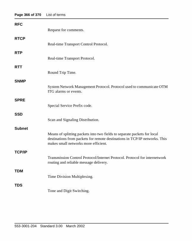
Page 366 of 370 List of terms
RFCRequest for comments.
RTCPReal-time Transport Control Protocol.
RTPReal-time Transport Protocol.
RTTRound Trip Time.
SNMPSystem Network Management Protocol. Protocol used to communicate OTM ITG alarms or events.
SPRESpecial Service Prefix code.
SSDScan and Signaling Distribution.
SubnetMeans of splitting packets into two fields to separate packets for local destinations from packets for remote destinations in TCP/IP networks. This makes small networks more efficient.
TCP/IPTransmission Control Protocol/Internet Protocol. Protocol for internetwork routing and reliable message delivery.
TDMTime Division Multiplexing.
TDSTone and Digit Switching.
553-3001-204 Standard 3.00 March 2002
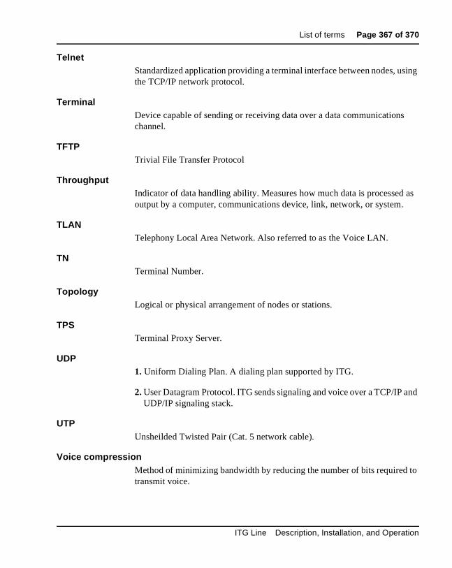
List of terms Page 367 of 370
TelnetStandardized application providing a terminal interface between nodes, using the TCP/IP network protocol.
TerminalDevice capable of sending or receiving data over a data communications channel.
TFTPTrivial File Transfer Protocol
ThroughputIndicator of data handling ability. Measures how much data is processed as output by a computer, communications device, link, network, or system.
TLANTelephony Local Area Network. Also referred to as the Voice LAN.
TNTerminal Number.
TopologyLogical or physical arrangement of nodes or stations.
TPSTerminal Proxy Server.
UDP1. Uniform Dialing Plan. A dialing plan supported by ITG.
2. User Datagram Protocol. ITG sends signaling and voice over a TCP/IP and UDP/IP signaling stack.
UTPUnsheilded Twisted Pair (Cat. 5 network cable).
Voice compressionMethod of minimizing bandwidth by reducing the number of bits required to transmit voice.
ITG Line Description, Installation, and Operation

Page 368 of 370 List of terms
VoIPVoice over IP. Used synonymously with XoIP.
VTNVirtual Terminal Number.
XoIPVoice or Fax over IP.
WANWide Area Network. Network using common carrier-provided lines that covers an extended geographical area. Contrast with LAN.
553-3001-204 Standard 3.00 March 2002
Page 369 of 370
370
Index
Aalarm files, 213Bbackplanes
connectors, 223I/O panel connections, 224
backup, 183
Cconnector pin assignments
NT8D02 Digital Line Card, 218connectors, 223
Eelectro-magnetic compatibility, 246electro-magnetic emissions, 246electro-magnetic immunity, 247environmental specifications
NT8D02 Digital Line Card, 37environmental specs, 244
Hhardware, 44
II/O panels
backplane connections, 224IPE modules
cable connections, 224
Llog files, 213
Mmean time between failures, 243MICB
regulatory standards, 245
NNT8D02 Digital Line Card
connector pin assignments, 218environmental specifications, 37
NT8D37 IPE Modulescable connections, 224
NT8D37BA IPE Modules, 224NT8D37EC IPE Modules, 224
Ooperational parameters, 189operational report, 175
Rreliability, 243
Ssafety regulations (table), 245SNMP traps, 198standards, regulatory, 245
Ttemperature specifications, 244
ITG Line Description, Installation, and Operation

Page 370 of 370 Index
553-3001-204 Standard 3.00 March 2002


1
Family Product Manual Contacts Copyright FCC notice Trademarks Document number Product release Document release Date Publish
Internet Telephony Gateway (ITG) LineDescription, Installation, and Operation
Copyright © 1999 - 2002 Nortel NetworksAll Rights ReservedInformation is subject to change without notice. Nortel Networks reserves the right to make changes in design or components as progress in engineering and manufacturing may warrant. This equipment has been tested and found to comply with the limits of a Class A digital device pursuant to Part 15 of the FCC rules and the radio interference regulations of Industry Canada. These limits are designed to provide reasonable protection against harmful interference when the equipment is operated in a commercial environment. This equipment generates, uses and can radiate radio frequency energy, and if not installed and used in accordance with the instruction manual, may cause harmful interference to radio communications. Operation of this equipment in a residential area is likely to cause harmful interference in which case the user will be required to correct the interference at their own expense.SL-1, Meridian 1, and Succession are trademarks of Nortel Networks.Publication number: 553-3001-204Document release: Standard 3.00Date: March 2002Printed in Canada
TM