meridian1 telephoneandattendantconsole installation
TRANSCRIPT

Meridian 1
Telephone and Attendant ConsoleInstallation
Document Number: 553-3001-215Document Release: Standard 12.00Date: January 2002
Year Publish FCC TM
Copyright © 1989 – 2002 Nortel NetworksAll Rights Reserved
Printed in Canada
Information is subject to change without notice. Nortel Networks reserves the right to make changes in designor components as progress in engineering and manufacturing may warrant. This equipment has been testedand found to comply with the limits for a Class A digital device pursuant to Part 15 of the FCC rules, and theradio interference regulations of Industry Canada. These limits are designed to provide reasonable protectionagainst harmful interference when the equipment is operated in a commercial environment. This equipmentgenerates, uses and can radiate radio frequency energy, and if not installed and used in accordance with theinstruction manual, may cause harmful interference to radio communications. Operation of this equipment in aresidential area is likely to cause harmful interference in which case the user will be required to correct theinterference at their own expense.
SL-1 and Meridian 1 are trademarks of Nortel Networks.


Page 3 of 144
4
Revision historyJanuary 2002
Standard 12.00. This document is up-issued to include content changes forMeridian 1 Internet Enabled Release 25.40.
April 2000Standard 11.00. This is a global document and is up-issued for X11Release 25.0x.
June 1999Standard, release 10.00. Issued for X11Release 24 changes.
October 1997Standard, release 9.00. Issued for X11 Release 23 changes.
August 1996Standard, release 8.00. Issued for X11 Release 22 changes.
July 1995Standard, release 7.00. Issued for X11 Release 21 changes.
December 1994Standard, release 6.00. Issued for X11 Release 20 to include editorialchanges, indexing, and Global Console updates.
December 1992Standard, release 5.00. Issued to include updates for X11 Release 18.
December 1991Standard, release 3.00. Issued to updated attendant console connections andASM installation.
Standard, release 4.00 was omitted.
Telephone and Attendant Console Installation

Page 4 of 144 Revision History
December 1990Standard, release 2.00. Updated to include Attendant Supervisory Module(ASM) installation and telephone acceptance tests.
December 1989Standard, release 1.00. Reissued for compliance with Nortel Networksstandard 164.0, and to incorporate corrections and updated information.
553-3001-215 Standard 12.00 January 2002

1
Contents
About this document . . . . . . . . . . . . . . . . . . . . . . . 3
Wiring installation . . . . . . . . . . . . . . . . . . . . . . . . . . 5Contents . . . . . . . . . . . . . . . . . . . . . . . . . . . . . . . . . . . . . . . . . . . . . . . . 5
Wiring for telephones and attendant consoles . . . . . . . . . . . . . . . . . . . 5
Install Wiring . . . . . . . . . . . . . . . . . . . . . . . . . . . . . . . . . . . . . . . . . . . . 7
Normal operating ranges . . . . . . . . . . . . . . . . . . . . . . . . . . . . . . . . . . . 8
Attendant console . . . . . . . . . . . . . . . . . . . . . . . . . . 9Contents . . . . . . . . . . . . . . . . . . . . . . . . . . . . . . . . . . . . . . . . . . . . . . . . 9
Reference list . . . . . . . . . . . . . . . . . . . . . . . . . . . . . . . . . . . . . . . . . . . . 9
Introduction . . . . . . . . . . . . . . . . . . . . . . . . . . . . . . . . . . . . . . . . . . . . . 9
Packing and unpacking . . . . . . . . . . . . . . . . . . . . . . . . . . . . . . . . . . . . . 9
Installation and removal . . . . . . . . . . . . . . . . . . . . . . . . . . . . . . . . . . . . 10
Designating attendant consoles . . . . . . . . . . . . . . . . . . . . . . . . . . . . . . 14
Cross-connecting attendant consoles . . . . . . . . . . . . . . . . . . . . . . . . . . 18
Telephones . . . . . . . . . . . . . . . . . . . . . . . . . . . . . . . 27Contents . . . . . . . . . . . . . . . . . . . . . . . . . . . . . . . . . . . . . . . . . . . . . . . . 27
Reference list . . . . . . . . . . . . . . . . . . . . . . . . . . . . . . . . . . . . . . . . . . . . 27
Packing and unpacking . . . . . . . . . . . . . . . . . . . . . . . . . . . . . . . . . . . . . 28
Installation and removal . . . . . . . . . . . . . . . . . . . . . . . . . . . . . . . . . . . . 28
i2004 Internet Telephone . . . . . . . . . . . . . . . . . . . . . . . . . . . . . . . . . . . 45
Designating telephones . . . . . . . . . . . . . . . . . . . . . . . . . . . . . . . . . . . . 49

2
Connecting telephones . . . . . . . . . . . . . . . . . . . . . . . . . . . . . . . . . . . . . 51
Cross-connecting telephones . . . . . . . . . . . . . . . . . . . . . . . . . . . . . . . . 52
Add-on modules . . . . . . . . . . . . . . . . . . . . . . . . . . . 59Contents . . . . . . . . . . . . . . . . . . . . . . . . . . . . . . . . . . . . . . . . . . . . . . . . 59
Reference list . . . . . . . . . . . . . . . . . . . . . . . . . . . . . . . . . . . . . . . . . . . . 59
Packing and unpacking . . . . . . . . . . . . . . . . . . . . . . . . . . . . . . . . . . . . . 60
Attendant Supervisory Module (M2250 console) . . . . . . . . . . . . . . . . 72
M2000 Series Meridian Digital Telephones . . . . . . . . . . . . . . . . . . . . 78
Analog Terminal Adapter . . . . . . . . . . . . . . . . . . . . . . . . . . . . . . . . . . . 80

Page 3 of 144
4
About this documentThis document is a global document. Contact your system supplier or yourNortel Networks representative to verify that the hardware and softwaredescribed is supported in your area.
This document applies to the Meridian 1 Internet Enabled system.
This document contains the installation procedures for attendant consoles,telephones, and add-on modules. See Figure 1 on page 4 for apparatusdesignations.
“Wiring installation” on page 5 includes information about the wiring forcurrent Nortel Networks telephones and the M2250 Attendant Console.
“Wiring installation” on page 5 describes the installation and removal processfor QCW-type and M1250/M2250 attendant consoles.
“Telephones” on page 27 provides procedures for installing and removing theM1109, M2000, M2006/M2008, M2016S, M2216, M2616, and M3000telephones.
“Add-on modules” on page 59 includes installation and removal informationfor all add-on modules and options for all telephones and attendant consoles.
Note: There are two distinct versions of Modular telephone sets – bothare supported. The versions can be clearly distinguished by the first fourletters in the model identification label on the bottom of the set. The twotypes are the “NTZK” models and the “NT2K” models. Whenappropriate, differences are noted in this document.
Telephone and Attendant Console Installation

Page 4 of 144 About this document
Note: See M3900 Series Meridian Digital Telephones: Description,Installation, and Administration (553-3001-216) for information oninstallation of the M3901, M3902, M3903, M3904, and M3905telephones.
Figure 1Apparatus designations
Connecting Block
Amphenol connector
Service Fitting
32
32
32
32
32CableMarker
UtilityColumn 553-1858
553-3001-215 Standard 12.00 January 2002

Page 5 of 144
8
Wiring installationContents
This section contains information on the following topics:
Wiring for telephones and attendant consoles. . . . . . . . . . . . . . . . . . . . 5
Install Wiring. . . . . . . . . . . . . . . . . . . . . . . . . . . . . . . . . . . . . . . . . . . . . 7
Normal operating ranges. . . . . . . . . . . . . . . . . . . . . . . . . . . . . . . . . . . . 8
Wiring for telephones and attendant consolesThis chapter discusses the installation and removal procedures for wiringtelephones and attendant consoles.
Each analog (500/2500-type) or digital telephone requires one pair of Zstation wire or equivalent. Existing 16- or 25-pair connector cables can beused. Each attendant console requires a 16-pair cable terminated on anAmphenol connector.
When zone cabling and conduit are used, assign a block of numbers or lettersto each zone. See Figure 2 on page 6. Allow for growth when assigningblocks of numbers.
Cable markers are normally an adhesive-backed cloth tape 1/2 inches wide by3-1/2 inches long (15 mm by 65 mm) with preprinted numbers.
For limits and cabling for analog (500/2500-type) telephones, refer toFigure 3 on page 7.
For a list of terminal connections, see Table 1 on page 8.
Telephone and Attendant Console Installation

Page 6 of 144 Wiring installation
Figure 2Zone cabling and conduit assignment
Zone Zone Zone Zone
Zone Conduit
Each Zone isapproximately600-800 feet
1.2
1.1
1
2.12.2
2
3 4
5 6 78
9
1011
12
13 14 15 16
17
18 19 20
ApparatusCloset
553-5232
SatelliteCloset
553-3001-215 Standard 12.00 January 2002

Wiring installation Page 7 of 144
Install WiringFollow this procedure to install the wiring.
Procedure 1Installing wiring
1 Assign a number to the wire or cable used.
2 Attach the assigned number to the wire or cable at the end nearest thetelephone, using a cable marker.
3 Run the wire or cable between the telephone location and nearestcross-connect point (if not previously run).
4 Connect the cable or wire to the telephone connecting block.
5 Designate the telephone connecting block.
6 Cross-connect the pairs at intermediate cross-connect points (ifrequired) and terminate at the cross-connect terminal.
Figure 3NE-analog (500/2500-type) telephones – limits and cabling
X Connecting block(QBB1A or Equivalent)
One pair (Z station wire orequivalent) Maximum range1000½
Modular cross-connect terminal
White Field
Jumper Channel
Blue Field
50 pair NE 66 type blocksNE 66 QC100 blocks orequivalent
553-1874
Telephone and Attendant Console Installation

Page 8 of 144 Wiring installation
7 Terminate leads at the cross-connect terminal and designate theblocks according to the house cable plan.
Normal operating rangesTelephones
M2000 Series Meridian Digital Telephones have a maximum permissibleloop length of 3500 ft (915 m), assuming 24 AWG (0.5 mm) wire with nobridge taps. A 15.5 dB loss at 256 kHz defines the loop length limit.
Attendant consoles
The M2250 attendant console has a maximum permissible loop length of3500 ft (915 m), assuming 24 AWG (0.5 mm) wire with no bridge taps. A15.5 dB loss at 256 kHz defines the loop length limit.
Table 1Terminal connections
Connecting blockDesignations
Inside wiringColors
NE-47QA orQBB1B
NE-284-74-5001 adapter
NE-625FTELADAPT
plugs and jacksZ station wire 16/25-pair cable
G 1T T1 (G) G W-BL
R 1R R1 (R) R BL-W
BK X1 AUX (BK) BK W-O
Y X2 GND (Y) Y O-W
5 R T2 (BL) W-SL
6 B R2 (W) SL-W
553-3001-215 Standard 12.00 January 2002

Page 9 of 144
26
Attendant consoleContents
This section contains information on the following topics:
Packing and unpacking. .. . . . . . . . . . . . . . . . . . . . . . . . . . . . . . . . . . . . 9
Installation and removal. . . . . . . . . . . . . . . . . . . . . . . . . . . . . . . . . . . . . 10
Designating attendant consoles . . . . . . . . . . . . . . . . . . . . . . . . . . . . . . . 14
Cross-connecting attendant consoles. . . . . . . . . . . . . . . . . . . . . . . . . . . 18
Reference listThe following are the references in this section:
• Meridian 1 Attendant PC: Software Installation Guide
• Circuit Card: Installation and Testing (553-3001-211)
• Software Input/Output Guide Administration (553-3001-311)
IntroductionThis section describes installation instructions for the M2250 attendantconsole. ForMeridian 1Attendant PC Software installation instructions, referto Meridian 1 Attendant PC: Software Installation Guide.
Packing and unpackingUse proper care while unpacking any attendant console. Check for damagedcontainers so that appropriate claims can be made to the transport companyfor items damaged in transit.
Telephone and Attendant Console Installation
Page 10 of 144 Attendant console
If an attendant console must be returned to the factory, pack it in theappropriate container to avoid damage during transit. Remember to includeall loose parts (cords, handset, power unit, labels, and lenses) in the shipment.
Installation and removalUse the following procedures to install and remove M2250 attendantconsoles.
Note: Although M2250 attendant consoles do not require a staticdischarge ground connection, the connection should be installed toprotect any earlier vintage attendant consoles that may be used asreplacements.
Choose a clean, level work surface and place several sheets of soft, cleanpaper between the attendant console and the work surface. This will preventscratching or otherwise damaging the top cover, LCD indicators and screen,and the feature keys of the attendant console.
Procedure 2Installing the M2250 attendant console
1 Ensure that a 16-pair or 25-pair cable equipped with a 25-pairAmphenol connector is installed at the attendant console’s location.
2 Unpack and inspect the attendant console for damage. If the consoleis damaged, notify your supplier.
3 Designate the console according to the features provided.
4 Connect the Amphenol plug on the attendant console to the Amphenoljack coming from the Main Distribution Frame (MDF).
• Fasten the Amphenol connectors together and secure thecaptive screws on the cable.
• Ensure that the connectors are secured in a connectormounting, if provided, or to the wall. Do not leave connectorsunprotected on the floor.
5 Add a line circuit for the attendant console, if not already done. Referto Circuit Card: Installation and Testing (553-3001-211).
6 Cross-connect the attendant console at the cross-connect terminal.See Procedure 1 on page 18.
553-3001-215 Standard 12.00 January 2002

Attendant console Page 11 of 144
7 Enter the related attendant console data in the Meridian 1 system.Refer to the Software Input/Output Guide Administration(553-3001-311).
8 Test the console features using the attendant console user guide.
Note: Refer to Circuit Card: Installation and Testing (553-3001-211)for circuit card installation procedures.
Procedure 3Removing the M2250 attendant console
1 Remove related attendant console data from the system memory.Refer to the Software Input/Output Guide Administration(553-3001-311).
2 Locate and remove cross-connections from the attendant consolecable at the cross-connect terminal. See Procedure 1 on page 18.
3 Remove the circuit card if required. Refer to Circuit Card: Installationand Testing (553-3001-211).
Note: Do not remove the circuit card if any of the remaining units onthe card are assigned.
4 Disconnect the Amphenol connector on the end of the cable that leadsto the cross-connect terminal from the connector on the cable leadingto the attendant console.
5 Pack the attendant console, handset, and cords in a suitablecontainer.
Procedure 1Removing theM2250 attendant console top cover
1 Disconnect any plugs and cords from the attendant console.
2 Remove the ten 10-mm fastening screws in the flange of the attendantconsole, as well as one 10-mm and one 40-mm screw on the base ofthe attendant console. See Figure 4 on page 12 for the M2250assembly drawing.
3 Holding the top cover and the base together by hand, turn theattendant console right-side up and place it back on the work surface.
Telephone and Attendant Console Installation

Page 12 of 144 Attendant console
4 Carefully lift the faceplate straight up and disconnect the 20-pin plugribbon cable located at J2.
Note: On attendant consoles with a display attached to the top cover, donot connect or disconnect the cable to the display unless the attendantconsole line cord is disconnected.
Figure 4M2250 assembly drawing (exploded view)
553-1306
LCD screenhinge assembly
Faceplateassembly
Ribbon cable
Base housingassembly
Support screw(1 of 10) LCD screen
553-3001-215 Standard 12.00 January 2002

Attendant console Page 13 of 144
Procedure 2Installing the M2250 attendant console top cover
1 Set theQMT2 dip switch. To locate the dip switch, look at the attendantconsole from the top. The QMT2 dip switch is the only dip switch onthe topmost circuit board. Set the switch to ON (enable QMT2) or OFF(disable QMT2).
Note: The QMT2 feature must be enabled in system software. Referto LD 12 in the Software Input/Output Guide Administration(553-3001-311).
2 Carefully lift the top cover straight up and connect the 20-pin plugribbon cable to J2.
3 Put the top cover back on the attendant console:
• Place the top cover onto the base housing, and turn theattendant console upside down.
• Reinsert and tighten the ten 10-mm fastening screws on theflange.
• Reinsert and tighten one 10-mm and one 40-mm fasteningscrew on the back.
4 Return the attendant console to its working position, reconnect theplugs and cords, and test the features.
Procedure 3Loopback test on the M2250 attendant console
1 Make a loopback connector. Prepare a blank 25-way RS-232 plug byinternally connecting pins 2 and 3 together with strapping wire.
2 Press the Shift key. This accesses Level 1 mode.
3 Press the F4 Function key to access the Diagnostics menu on theliquid crystal display (LCD) screen.
4 Plug the loopback connector into the Data Port RS-232 jack in the backof the console.
Telephone and Attendant Console Installation

Page 14 of 144 Attendant console
5 Select the Data Port option from the Diagnostics menu by dialing “3”.The LCD screen displays OK when the test is successfully completed.
If there is a hardware fault on the M2250, A0H is displayed.
If the blank RS-232 connector is not plugged into the data portcorrectly (Step 4), the display reads 90H or A0H.
6 Press the Asterisk (*) key to repeat the test.
7 To exit the test mode press the octothorpe (#). This returns you to themain Diagnostics menu.
8 Press the octothorpe to return to normal operating mode.
9 Remove the loopback connector from the Data Port RS-232 jack.
Designating attendant consolesRefer to the work order to determine the features and key designations foreach attendant console. Designate each key on the attendant console byplacing its feature name (from the designation sheet) in the key cap that fitson the key.
The Directory Number (DN) designation window on the M2250 attendantconsole is located above the keypad.
Procedure 4Designating attendant consoles
1 Remove the cap from each key requiring a designation by gentlypulling upward on the cap.
2 Remove the appropriate designation from the sheet of designations.
3 Place the designation in the cap, place the cap over the correspondingkey, and gently press down. Repeat this procedure for all keysrequiring designations.
4 Insert a paper clip in the hole at the left or right end of the DNdesignation window. Pry the window open.
5 Insert the number tag, and replace the designation window.
553-3001-215 Standard 12.00 January 2002

Attendant console Page 15 of 144
The following figures show the typical key designations for the M2250attendant console:
• Figures 5 and 6 show the key designations for the M2250 attendantconsole in Shift mode.
• Figure 7 on page 17 and Figure 8 on page 17 show the M2250 attendantconsole in Unshift mode.
Figure 5M2250 key designations in Shift mode (QMT2 not enabled)
Note: These two keys are used as Trunk Group Busy keys 08 and 09 on the M2250 attendant console.
553-1497
EX SR
EX DS
RL SR
RL DS
BLF
SHIFT
TGB7
TGB6
TGB5
TGB4
TGB3
TGB2
TGB1
TGB0
ICI9
ICI8
ICI7
ICI6
ICI5
ICI4
ICI3
ICI2
ICI1
ICI0
LPK5
LPK4
LPK3
LPK2
LPK1
LPK0
RLS HOLD
FEAT9
FEAT8
FEAT7
FEAT6
FEAT5
FEAT4
FEAT3
FEAT2
FEAT1
FEAT0
C/H
CAS BSY
F1
OMN
F2
VDH
F4
DMN SS
CGM
SD
MODE
VUP
F3
BLF Functions onlyNote
1 2 3
4 5 6
7 8 9
0* #
Telephone and Attendant Console Installation

Page 16 of 144 Attendant console
Figure 6M2250 key designations in Shift mode (QMT2 enabled)
Note: The top two keys in these columns are used as Trunk Group Busy keys only on the M2250.Therefore, the numbering scheme is as follows:
M2250
TGB09TGB08TGB07TGB06TGB05TGB04TGB03TGB02TGB01TGB00
TGB19TGB18TGB17TGB16TGB15TGB14TGB13TGB12TGB11TGB10
Strip GOperating
and feature keys(Flexible assignment)
Strip ATrunk group busy
indicator and controlof T G access (flexible
assignment)
Strip BIncoming call
type indicatorsand selection keys
(flexible assignment)
Strip FOperating keys
(fixed assignment)
Strips C, D, and EOperating keys
(fixed assignment)
TGB9
TGB8
TGB7
TGB6
TGB5
TGB4
TGB3
TGB2
TGB1
TGB0
ICI9
ICI8
ICI7
ICI6
ICI5
ICI4
ICI3
ICI2
ICI1
ICI0
NITE
POSBSY
LPK5
LPK4
LPK3
LPK2
LPK1
LPK0
RLS
SRC
C
WM
JM
N
DEST
VOLUP
VOLDOWN
EXCLSRC
EXCLDEST
SIGSRC
SIGDEST
RLSSRC
RLSDEST
CONT
HOLD
1 2 3
4 5 6
7 8 9
0* #
Digit Display
553-3001-215 Standard 12.00 January 2002

Attendant console Page 17 of 144
Figure 7M2250 key designations in Unshift mode (QMT2 enabled)
Figure 8M2250 designations in Unshift mode (QMT2 not enabled)
553-1498
ICI09
ICI08
ICI07
ICI06
ICI05
ICI04
ICI03
ICI02
ICI01
ICI00
ICI19
ICI18
ICI17
ICI16
ICI15
ICI14
ICI13
ICI12
ICI11
ICI10
LPK5
LPK4
LPK3
LPK2
LPK1
LPK0
RLS
EX SR
EX DS
RL SR
RL DS
CONF 6
SHIFT
HOLD
FEAT9
FEAT8
FEAT7
FEAT6
FEAT5
FEAT4
FEAT3
FEAT2
FEAT1
FEAT0
C/H
CAS BSY
F1
OMN
F2
VDH
F4
DMN SS SDVUP
F3
1 2 3
4 5 6
7 8 9
0* #
553-6075
ICI9
ICI8
ICI7
ICI6
ICI5
ICI4
ICI3
ICI2
ICI1
ICI0
LPK5
LPK4
LPK3
LPK2
LPK1
LPK0
RLS
CONF6
SHIFT
EX SR
EX DS
RL SR
RL DS
HOLD
FEAT9
FEAT8
FEAT7
FEAT6
FEAT5
FEAT4
FEAT3
FEAT2
FEAT1
FEAT0
C/H
CAS BSY
F1 F2 F4
SS SD
F3
Scrolling
LCD Display Screen
(4 or 2 lines for M2250)
1 2 3
4 5 6
7 8 9
0* #
Telephone and Attendant Console Installation

Page 18 of 144 Attendant console
Cross-connecting attendant consolesTerminations are located on the vertical side of the distributing frame whenframe-mounted blocks are used and in the blue field when wall-mountedblocks are used.
Line circuit card (TN) terminations are located on the horizontal side of thedistributing framewhen frame-mounted blocks are used and in the white fieldwhen wall-mounted blocks are used.
Procedure 1Cross-connecting attendant consoles
1 Locate the attendant console terminations at the cross-connectterminal.
2 Connect Z-type cross-connecting wire to the leads of the attendantconsole.
3 Locate the line circuit card (TN) terminations.
4 Run and connect the other end of the cross-connecting wire to theassigned TN terminal block.
See Table 2 for details on Z-type cross-connecting wire and Table 3 onpage 19 for a list of inside wiring colors.
Table 2Z-type cross-connecting wire (Part 1 of 2)
Size Gauge Color Designation
1 pr 24 Y-BL Tip
BL-Y Ring
3 pr 24 W-BL Voice T
BL-W Voice R
W-O Signal T
O-W Signal R
553-3001-215 Standard 12.00 January 2002

Attendant console Page 19 of 144
W-G Power
G-W Power
Table 3Inside wiring colors
Z station wire 16/25-pair cableConnect toequipment TN
G W-BL First pair Tip
R BL-W First pair Ring
BK W-O Second pair Tip
Y O-W Second pair Ring
Table 2Z-type cross-connecting wire (Part 2 of 2)
Size Gauge Color Designation
Telephone and Attendant Console Installation

Page 20 of 144 Attendant console
Figure 9M2250 attendant console cross-connections
See notes on page 21.
Cross connectblock
M2250 Console(console connector)
Note 2
+ VPS
VPS RTN
261
272
30 5
32 7
33 8
3611
3914
4116
4217
5025
Relay 2
Relay 1
TCM Primary
TCM Secondary
ASM
+AUX
W-BLBL-W
W-SLSL-W
BK-BLBL-BK
BK-BRBR-BK
Y-BLBL-Y
Y-OROR-Y
V-SLSL-V
R-OROR-R
R-GG-R
W-OROR-W
553-1872
To 1st TN
To 2nd TN
To 3rd TN
25 pair cable from console to MDF
GNDTCGNDALARM
To 4th TN Tip
To 5th TN Tip
To 4th TN Ring
To 5th TN Ring
Note 1 –AUX•
•
•
•
Code Blue
Part of Power Fail or Energy Transfer
Major Alarm
553-3001-215 Standard 12.00 January 2002

Attendant console Page 21 of 144
The following notes refer to Figure 9 on page 20, which illustrates theM2250attendant console cross-connections.
Note 1: TheM2250 is powered by means of the line circuits. In additionto the primary TN, secondary TN, and ASM TN, two TNs are cabled totheM2250 using the +AUX and –AUX leads. The maximum loop lengthis 3000 ft of 24 AWG wire.
Note 2: When additional options are used (BLF or display backlightoption), an additional 16 V dc power supply is required. The 16 V dcsource is cabled using +VPS and VPS RTN leads. The maximumdistance from the console to the power source is 120 feet of 24 AWGwire. Please note if both options are installed, only one 16 V dc powersupply is required.
Note 3: It is recommended that five consecutive TNs on the line circuitbe allocated for each console.
Note 4: When used with the ISDLC, the M2250 requires QPC578vintage D or later.
Note 5: The third TN must be cross-connected to the console cableWH/SL pair whether or not an ASM (Attendant Supervisory Module) isinstalled. This third TN provides additional console power which isrequired.
Table 4 on page 22 explains where each M2250 cable pair is connected.Table 5 on page 24 lists the M2250 typical cross-connections.
Telephone and Attendant Console Installation

Page 22 of 144 Attendant console
Table 4M2250 attendant console connections (Part 1 of 2)
Mounting cord 16/25-pair connector cable
Leaddesignation
Pinnumber
Pairnumber
Color Connected to
TCM primary 26
1
1T
R
W-BL
BL-W
TN #1
TCM secondary 27
2
2T
R
W-O
O-W
TN #2
AttendantSupervisoryModule
30
5
5T
R
W-SL
SL-W
TN #3
Spare 31
6
6T
R
R-BL
BL-R
+AUX 32
7
7T
R
R-O
O-R
TN #4
–AUX 33
8
8T
R
R-G
G-R
TN #5
Spare 34
9
9T
R
R-BR
BR-R
Spare 35
10
10T
R
R-SL
SL-R
Power Fail or
Energy Transfer
36
11
11T
R
BK-BL
BL-BK
GND (Note 1)
TC (Note 2)
Spare
Spare
Spare
Spare
37
12
38
13
12T
R
13T
R
BK-O
O-BK
BK-G
G-BK
553-3001-215 Standard 12.00 January 2002

Attendant console Page 23 of 144
GND
Major Alarm
39
14
14T
R
BK-BR
BR-BK
GND (Note 1)
ALM (Note 2)
Spare 40
15
15T
R
BK-SL
SL-BK
VPS 41
16
16T
R
Y-BL
BL-Y
VPS RTN 42
17
17T
R
Y-O
O-Y
Spare
Code Blue 50
25
25T
R
Y-SL
SL-Y
Relay 2
Relay 1
Note 1: Connect to Pin 3 or 28 of the appropriate PFJ5 terminal block.
Note 2: Connect TC to Pin 29 or 5 and ALM to Pin 4 or 31 of the appropriate PFJ5terminal block.
Table 4M2250 attendant console connections (Part 2 of 2)
Mounting cord 16/25-pair connector cable
Leaddesignation
Pinnumber
Pairnumber
Color Connected to
Telephone and Attendant Console Installation

Page 24 of 144 Attendant console
Table 5M2250 typical cross-connections (Part 1 of 2)
Pair PinsPairColor
DLCConnections
ISDLCConnections
1T
1R
26
1
W-BL
BL-W
Unit
0
Unit
0
2T
2R
27
2
W-O
O-W
Unit
1
Unit
8
3T
3R
28
3
W-G
G-W
Unit
2
Unit
1
4T
4R
29
4
W-BR
BR-W
Unit
3
Unit
9
5T
5R
30
5
W-S
S-W
Unit
4
Unit
2
6T
6R
31
6
R-BL
BL-R
Unit
5
Unit
10
7T
7R
32
7
R-O
O-R
Unit
6
Unit
3
8T
8R
33
8
R-G
G-R
Unit
7
Unit
11
9T
9R
34
9
R-BR
BR-R
Unit
8
Unit
4
10T
10R
35
10
R-S
S-R
Unit
9
Unit
12
11T
11R
36
11
BK-BL
BL-BK
Unit
10
Unit
5
12T
12R
37
12
BK-O
O-BK
Unit
11
Unit
13
553-3001-215 Standard 12.00 January 2002

Attendant console Page 25 of 144
13T
13R
38
13
BK-G
G-BK
Unit
12
Unit
6
14T
14R
39
14
BK-BR
BR-BK
Unit
13
Unit
14
15T
15R
40
15
BK-S
S-BK
Unit
14
Unit
7
16T
16R
41
16
Y-BL
BL-Y
Unit
15
Unit
15
Table 5M2250 typical cross-connections (Part 2 of 2)
Pair PinsPairColor
DLCConnections
ISDLCConnections
Telephone and Attendant Console Installation

Page 26 of 144 Attendant console
553-3001-215 Standard 12.00 January 2002

Page 27 of 144
58
TelephonesContents
This section contains information on the following topics:
Packing and unpacking. .. . . . . . . . . . . . . . . . . . . . . . . . . . . . . . . . . . . . 28
Installation and removal. . . . . . . . . . . . . . . . . . . . . . . . . . . . . . . . . . . . . 28M2000 Series Meridian Digital Telephones self-test. . . . . . . . . . . . 32M2317 telephone self-test. . . . . . . . . . . . . . . . . . . . . . . . . . . . . . . . . 36M3900 Series Meridian Digital Telephone. . . . . . . . . . . . . . . . . . . . 44
i2004 Internet Telephone. . . . . . . . . . . . . . . . . . . . . . . . . . . . . . . . . . . . 45Manual first-time i2004 Internet Telephone installation. .. . . . . . . . 46Automatic first-time installation of an i2004 Internet Telephone. . . 46
Designating telephones. . . . . . . . . . . . . . . . . . . . . . . . . . . . . . . . . . . . . 49
Connecting telephones. . . . . . . . . . . . . . . . . . . . . . . . . . . . . . . . . . . . . . 51
Cross-connecting telephones. . . . . . . . . . . . . . . . . . . . . . . . . . . . . . . . . 51
Reference listThe following are the references in this section:
• Meridian Internet Telephony Gateway: Installation and Operation(553-3001-204)
• Circuit Card: Installation and Testing (553-3001-211)
• M3900 Series Meridian Digital Telephones: Description, Installation,and Administration (553-3001-216)
• Software Input/Output Guide Administration (553-3001-311)
Telephone and Attendant Console Installation

Page 28 of 144 Telephones
Packing and unpackingUse proper care while unpacking any digital telephone. Check for damagedcontainers so that appropriate claims can be made to the transport companyfor items damaged in transit.
If a telephone must be returned to the factory, pack it in the appropriatecontainer to avoid damage during transit. Remember to include all loose parts(cords, handset, power unit, labels, and lenses) in the shipment.
Installation and removalDo not remove the circuit card if any remaining units on the card are assigned.
Procedure 1Installing 500/2500 telephones
1 Ensure that the wiring is installed at the telephone’s location.
2 Unpack and inspect the telephone for damage. Assemble the handsetand line cords if necessary.
3 Install the required designations on the telephone.
4 Connect the telephone to the connecting block or connector.
5 Cross-connect the telephone wiring at the cross-connect terminal.
6 Configure the telephone in the system. Refer to the SoftwareInput/Output Guide Administration (553-3001-311).
Procedure 2Removing 500/2500 telephones
1 Remove telephone data from the system. Refer to the SoftwareInput/Output Guide Administration (553-3001-311).
2 Disconnect the telephone from the connecting block or connector.
3 Pack the telephone in a container.
4 If necessary, remove the cross-connections for the telephone at thecross-connect terminal.
553-3001-215 Standard 12.00 January 2002

Telephones Page 29 of 144
5 Remove the line circuit card if required. Refer to Circuit Card:Installation and Testing (553-3001-211).
Procedure 3Installing M2000 Series Meridian Digital Telephones(M2006/M2008/M2008HF/M2016S/M2616/M2216ACD)
1 Complete the wiring and cross-connections (loop power) beforeconnecting the telephone to the connecting block. See Figure 10 onpage 30 and Figure 11 on page 31.
2 Place the telephone upside down on a number of sheets of soft, cleanpaper on a solid, level work surface to prevent damage to movablekeys and the telephone’s face.
3 Connect the handset cord (5-conductor TELADAPT connectors) to thehandset and snap it into place (not applicable to M2216ACD).
4 Connect the other end of the handset cord to the connector in thebottom cover of the telephone. Turn the smooth side of the handsetcord up (away from the telephone bottom cover) before tucking it underthe restraining tab to ensure that the telephone will sit level on the deskafter installation is complete (not applicable to M2216ACD).
5 Connect the line cord to the telephone bottom cover. Route the cordthrough the channels.
6 Turn the telephone right side up and place it in the normal operatingposition.
7 Print the directory number on the designation card. Using a paper clip,remove the number lens from the telephone. Insert the designationcard and snap the lens back into place.
8 Designate the feature keys.
9 Insert the line cord TELADAPT connector into the connecting blockand snap it into place.
10 Perform the self-test (see Procedure 1) and acceptance testprocedures. See LD 31 in the Software Input/Output GuideAdministration (553-3001-311).
11 Supply the user with a quick reference card and all userdocumentation. Make sure the SPRE number is printed on the quickreference card.
Telephone and Attendant Console Installation

Page 30 of 144 Telephones
Figure 10M2000 Series Meridian Digital Telephone connections
Note: The optional power may be required only if the set has options such as the Meridian ProgrammableData Adapter.
MeridianDigital
Telephone
MeridianSL-1
White
Black
(R)
(T)
Red
Green
Yellow
Blue
Wall mounttransformer
To closetPower Supply
553-1886
Alternate power
553-3001-215 Standard 12.00 January 2002

Telephones Page 31 of 144
Figure 11M2000 Series Meridian Digital Telephone cross-connections
Unit 0
Unit 1
Unit 6
Unit 7
T0R0
T1R1
T6R6
T7
R7
261
283
3813
4016
W-BLBL-W
W-GG-W
BK-GG-BK
BK-S
S-BK
T0R0
T1R1
T6R6
T7
R7
GR
WB
Line cordto telephoneFor PowerSupply leads
to telephone
to telephone
to telephone
PE shelfLinePack
Packconnector
Part of25 pair cable
Shelf connector
Part of 25pair cable
Cross connectblock
Telephone connecting
block, or connector
553-1885
Telephone and Attendant Console Installation

Page 32 of 144 Telephones
M2000 Series Meridian Digital Telephones self-testM2000 Series Meridian Digital Telephones have a self-testing capability.Follow the steps in Procedure 1 to perform the self-test after installing anM2000 Series Meridian Digital Telephone or any of the hardware options toensure proper operation.
Procedure 1M2000 Series Meridian Digital Telephones self-test
1 Unplug the line cord from the telephone.
2 While holding down the RLS key, plug in the line cord to the telephone.Let go of the RLS key.
3 Use Table 6 to perform the necessary steps and check results.
Table 6Meridian Modular Telephones self-test steps and results (Part 1 of 2)
Step Action Result
1 Begin test (plug in line cord whileholding down the RLS key).
The handset is on hook.
Speaker beeps once, all LCDs flash.
Message Waiting lamps light steadily.
Display reads: LOCALDIAGNOSTICMODE
PRESS RLS KEY TO EXIT
2 Press each Function key, from zero tofifteen (if you have Key ExpansionModules, continue pressing theFunction keys, in any order).
Adjacent LCD goes off when a key ispressed.
3 Press the Hold key. Speaker beeps.
4 Press each dial pad key. Speaker beeps each time a key is pressed.
5a Lift the handset (if applicable). Speaker beeps.
Press the dial pad keys. Handset beeps.
Replace the handset.
553-3001-215 Standard 12.00 January 2002

Telephones Page 33 of 144
5b Plug in the headset (if applicable). Speaker beeps.
Press the dial pad keys. Headset beeps.
Unplug the headset.
6 Press the right side of the volumecontrol key.
Speaker beeps.
Display is filled with dark squares.
Press the right side of the volumecontrol key.
Speaker beeps.
Display is blank.
Press the right side of volume controlkey.
Speaker beeps.
Display shows symbols including digits 0–9and uppercase alphabet
Press the right side of the volumecontrol key.
Speaker beeps.
Display shows symbols including upper- andlowercase alphabet.
Press the right side of the volumecontrol key.
Speaker beeps.
Display shows various symbols.
Press the right side of the volumecontrol key.
Speaker beeps.
Display shows symbols.
Press the right side of the volumecontrol key.
Speaker beeps.
Display is filled with dark squares.
7 Press the RLS key (end of test). Message Waiting lamp goes off.
Display shows idle screen within 10 seconds.
Table 6Meridian Modular Telephones self-test steps and results (Part 2 of 2)
Step Action Result
Telephone and Attendant Console Installation

Page 34 of 144 Telephones
Procedure 2Installing the M2317 telephone
1 Complete the wiring and cross-connection according to Figure 12before connecting the telephone to the TELADAPT connector block.
2 Place the telephone upside down on a number of sheets of soft, cleanpaper and on a solid, level work surface to prevent damage to movablekeys and the telephone’s face.
3 Connect the handset cord 4-conductor TELADAPT connectors to thehandset and to the telephone and snap into place.
4 Turn the smooth side of the cord away from the telephone base andsecure it under the restraining tab. This ensures that the telephone sitslevel after the installation is complete.
5 Connect the 6-conductor line cord to the telephone base, and place itunder the restraining tabs.
6 Turn the telephone face up, and place it in the normal operatingposition.
7 Print the directory number (DN) on the designation card and place it inthe designation card holder.
8 Designate button labels for programmable keys, and place them underthe button cover.
9 Insert the line cord TELADAPT connector block and snap it into place.Place the line cord under the restraining tabs.
10 Plug the 5 V power supply connector into the back of the telephone.
11 Plug the power supply into an AC utility outlet.
12 After the M2317 digital telephone is connected to a line that is bothenabled and designated as an M2317 digital line, the startup screendisplays INITIALIZATIONV6.4.Within 5 seconds, the Idle state screenis displayed, and the M2317 is operational. The term V6.4 representsthe firmware issue number, and may differ with some installations.
13 If the M2317 has been connected to a line that is designated as adigital line, but is not enabled, the display will prompt CONTACTSYSTEM ADMINISTRATOR. The line must be enabled using LD 32from the maintenance terminal, and by enabling the features outlinedin the work order. Refer to the Software Input/Output GuideAdministration (553-3001-311) for the required routines, prompts, andresponses.
553-3001-215 Standard 12.00 January 2002

Telephones Page 35 of 144
If the M2317 has been connected to a line that is neither defined as adigital line nor enabled, refer to the Software Input/Output GuideAdministration (553-3001-311) for required routines, prompts, andresponses.
14 Verify that all the requested features are enabled by accessing themwith the soft keys, or programmable keys, from the M2317 telephoneand observing the display screen.
15 Perform the self-test (see Procedure 1 on page 36) and acceptancetest procedures. See LD 31 in the Software Input/Output GuideAdministration (553-3001-311).
Figure 12M2317 digital telephone cross-connections
Unit 0
Unit 1
Unit 6
Unit 7
T0R0
T1R1
T6R6
T7
R7
261
283
3813
40
16
W-BLBL-W
W-GG-W
BK-G
G-BK
BK-S
S-BK
T0R0
T1R1
T6R6
T7
R7
GR
Line cordto telephone
to telephone
to telephone
to telephone
PE shelf
Linepack
Packconnector
Part of25 pair cable
Shelf connector
Cross connectblock
Telephone connectingblock, or connector
553-1895Part of multi-pair cable
Telephone and Attendant Console Installation
Page 36 of 144 Telephones
M2317 telephone self-testTheM2317 telephone has a self-testing capability. This test can be performedwhether or not the telephone is connected to the system. The test checks theproper functioning of the keys and liquid crystal display (LCD) indicators onthe set. Follow the steps listed in Procedure 1 and Table 7 to perform theM2317 self-test.
Procedure 1M2317 telephone self-test
1 Connect the telephone to the ac power supply.
The LCD screen displays “Initialization … vX.X” (note that you haveonly 3 to 5 seconds to begin step 2).
2 Press softkey 5 twice, then press softkey 4 twice.
3 Use Table 7 to perform the necessary steps and check results.
4 Unplug the power supply to end the test.
553-3001-215 Standard 12.00 January 2002

Telephones Page 37 of 144
Table 7M2317 telephone key/LCD indicator self-tests
Step Key operated Required response
1 Any programmablekey
Toggles the corresponding indicator on/off
2 Any dial pad key Displays the corresponding character in the top line of thedisplay screen
3 Volume control Displays characters “>” for volume up and “<” for volume downin the top line of the display screen
4 Softkey 1 Both display lines are filled with characters as follows:ABCDEFGHIJKLMNOPQRSTUVWXYZABCDEFGHIJKLMNOPQRSTUVWXYZABCDEFGHIJKLMNOPQRSTUVWXYZAB
5 Softkey 2 Both display lines are filled with characters as follows:abcdefghijklmnopqrstuvwxyzabcdefghijklmnopqrstuvwxyzabcdefghijklmnopqrstuvwxyzab
6 Softkey 3 All LCD pixels are turned on
7 Softkey 4 Display is blank
8 Softkey 5 Both display lines are filled with characters as follows:88888888888888888888888888888888888888888888888888888888888888888888888888888888
Telephone and Attendant Console Installation

Page 38 of 144 Telephones
When the M2317 digital telephone or the data option fails to function properly,follow the steps listed in Table 8 in sequence to isolate the problem area.
Table 8M2317 trouble-locating procedures (Part 1 of 2)
Step Action
Loop power failure
1 Plug in the telephone.
2 The LCDs flash once to indicate the power is OK.
Data communication failure
1 If voice communication is normal but data communication fails, check for DC outputvoltage at the power supply connector pins or replace the power supply plug-intransformer.
Attempt to make a data call from the terminal keyboard (refer to Meridian 1Telephones: Description and Specifications (553-3001-108)). If not successful,proceed with step 2.
2 Make a call to the DN (voice or data) to verify that the port is enabled.
3 Use an EIA or RS-232 breakout box in conjunction with the terminal cable to verifylead states and replace or repair cable if pinouts are incorrect.
Attempt to make a data call from the terminal keyboard (refer to Meridian 1Telephones: Description and Specifications (553-3001-108)). If still not successful,proceed with step 4.
4 Remove the transformer from the AC receptacle, unplug the 5-pin power supplyconnector at the back of the telephone, and replace the data option circuit board (seeProcedure 1). Reconnect the data option power supply.
Make a new attempt to start a data call. If trouble persists, continue with the ISDLCfailure procedure.
5 Use the self-test procedure to verify that the telephone electronics are operatingcorrectly.
553-3001-215 Standard 12.00 January 2002

Telephones Page 39 of 144
ISDLC failure
1 Go to the system maintenance terminal (TTY or CRT) and check for displayed errorand location codes. An “NWS 401 L S C” or an “NWS 501 L S C U” code indicates thatthe automatic (routine) diagnostic test has detected a fault.
Check for the following indications:
L = faulty circuit card (ISDLC card) loop number
S = circuit card location (shelf number)
C = number of the faulty circuit card
U = unit number of a faulty telephone (appears only in conjunction with the NWS 501code)
2 Replace the faulty components.
Try to establish a call. If unsuccessful, check the telephone.
Telephone (voice or dialing) failure
1 Check the line cord and handset cord to determine if all TELADAPT connectors arefirmly in place and reconnect the loose ones. Ensure that the polarity of the Tip andRing leads is correct.
Lift the handset and listen for the dial tone and/or dial a directory number. Ifunsuccessful, proceed with step 2.
2 Wiggle the line cord and/or handset cord while listening for sounds from the handset. Ifcrackling or ticking sounds are heard, replace the cords.
Try to establish a call. If unsuccessful, proceed with step 3.
3 Replace the telephone.
Try to establish a call. If unsuccessful, proceed with step 4.
4 Check the wiring between the line card, distribution panel, and telephone for breaks orloose connections. If necessary, rerun the wiring.
Operate the telephone.
Note: If no error codes are shown at the maintenance terminal, the Network and Signaling Diagnostic(LD 30) can be loaded and run manually from the system TTY. Refer to the Software Input/Output GuideAdministration (553-3001-311).
Table 8M2317 trouble-locating procedures (Part 2 of 2)
Telephone and Attendant Console Installation

Page 40 of 144 Telephones
Procedure 2M2616CT Installation
WARNING
1 Complete the wiring and cross-connections (loop power) beforeconnecting the telephone to the connection block.
2 Place the telephone upside down on a padded level work surface toprevent damage to the telephone face.
3 connect the line cord into the bottom of the telephone base. Route thecord through the channels.
4 Plug the AC adapter (Class 2 power supply) output DIN connector intothe bottom of the M2616CT set next to the line cord connection. Routethe cord through the channels.
5 Turn the telephone right side up and place it in the normal operatingposition.
6 Insert the line cord TELEDAPT connector into the connecting block.
7 Plug the AC adapter (Class 2 power supply) input into the commercial11V electrical main outlet.
8 Print the directory number on the designation card. Using a paper clipremove the number lens from the telephone. Insert the designationcard and snap the lens back into place
9 Designate the feature keys.
DANGER OF ELECTRIC SHOCKThe M2616CT is not intended for direct connection tothe public switched network or other exposed plantnetworks, because the exposed pins on the handsetcradle (where the handset sits) creates a possibleoutlet for harmful voltage. The M2616CT is designedto be used with a Meridian PBX.
553-3001-215 Standard 12.00 January 2002

Telephones Page 41 of 144
Procedure 3M2616CT Installing the battery
1 Place the handset battery in the base of the handset so the batteryengages with the contact points.
2 Snap the battery into place.
3 Slide the spare battery (optional purchase) into the spare batterycompartment, located at the top of the handset cradle. The yellowindicator lights when the battery is properly connected.
The battery begins to charge as soon as the handset is placed in itscradle. The main handset battery 700 mAh fully recharges inapproximately 2.25 hours, the 1000 mAh battery charges inapproximately 2.50. It should be noted that the that the spare batterycharging port on the base unit provides a “trickle charge” that chargesthe battery at a slower rate than through the handset.
Telephone and Attendant Console Installation

Page 42 of 144 Telephones
Figure 13Installing the M2616CT battery
Procedure 1M2616CT Wall mounting
The M2616CT base is equipped with a reversible footstand that allows you tomount the telephone on the wall. The procedure is described as follows:
1 Remove the handset and place the telephone upside down on a levelwork surface covered with soft material to prevent damage to movablekeys and the telephone face.
2 Disconnect all cords from the set.
3 Remove the two screws from the footstand assembly.
WARNING: Do NOT plug stereo/audioheadset into the M2616CT jack. This could cause damage to the headset.
Main battery
Spare battery (optional) slides into baseContact points MUST meet Handset rests in cradle above battery
Contactpoints
Sparebattery
Spare battery indicator lightis yellow when battery is charging in spare port
Main battery indicator is red when battery is charging and green when battery is charged
1. Clip Main battery into back of handset.2. Place bottom of battery in position.3. Snap top of battery into place
Optional headset attaches to handset for
handsfree activity
553-8570
553-3001-215 Standard 12.00 January 2002

Telephones Page 43 of 144
4 Unsnap the footstand assembly by pressing inward at the back of thefootstand where it meets the base, and pulling upward.
5 Rotate the footstand 180 degrees and screw the footstand back intoplace to the set’s bottom cover.
6 Tighten all screws and replace all cords.
7 Mount the telephone on the wall using the wall-mount holes providedon the bottom of the footstand.
M2616CT configurationTo configure the M2616CT set refer to Software Input/Output GuideAdministration (553-3001-311) for complete information and procedures onLD11 to configure the Meridian Digital Telephone. For the Locator key (key14) to function, do not assign a feature to this key. Handsfree is required forthe M2616CT to function properly.
M2616CT Handset Registration to Base UnitEachM2616CT handset is automatically registered to its respective base unit.In cases where a substitute handset is required for troubleshooting purposes,a different M2616CT handset can be reregistered by placing the handseton-hook, and unplugging, then re-plugging in the ac power adapter andtelephone line cord.
M2616CT Manual RF (Radio Frequency selectionTheM2616CT uses 900 MHz narrowband signaling. Other products also usethese channels. Due to interference from other products, there may be a timewhen the installer must confirm the user’s M2616CT so that other 900 MHzproducts will not cause interference. The Manual RF Selection feature is afunction available on Key 14 in addition to the Locator feature. Procedure 2describes the steps to follow to implement the Manual RF Selection feature:
Procedure 2M2616CT Manual RF (Radio Frequency selection)
1 Add a feature (any feature) on the system’s Key 14.
2 Press Key 14 and AUTO appears on the display.
3 Toggle the volume key until the desired channel (CH00 through CH19)is reached. See Table 9.
Telephone and Attendant Console Installation

Page 44 of 144 Telephones
4 Press Key 14 again.
5 Remove the feature fromKey 14 to have access to the Locator feature.Selecting one channel instead of scanning provides quicker responseto the voice channel and clears the interference in the area.
M3900 Series Meridian Digital TelephoneThe M3900 Series Meridian Digital Telephones provide versatilefunctionality to the desktop environment. TheM3900 SeriesMeridianDigitalTelephones have five models:
• M3901 entry level telephone
• M3902 Basic Telephone
• M3903 Enhanced Telephone
• M3904 Professional Telephone
• M3905 Call Center Telephone
For more information on theM3900 SeriesMeridian Digital Telephone, refertoM3900 Series Meridian Digital Telephones: Description, Installation, andAdministration (553-3001-216).
Table 9Frequency Ranges
Channel Frequency Channel Frequency Channel Frequency Channel Frequency
CH00 902.6 CHO5 910.6 CH10 915.8 CH15 921.4
CH01 904.0 CH06 912.0 CH11 916.4 CH16 923.0
CH02 905.6 CH07 914.2 CH12 918.4 CH17 924.8
CH03 907.2 CH08 914.8 CH13 919.6 CH18 926.4
CH04 908.8 CH09 915.2 CH14 921.4 CH19 927.6
553-3001-215 Standard 12.00 January 2002
Telephones Page 45 of 144
i2004 Internet TelephoneThis section explains how to install the i2004 Internet Telephone and how toperform manual and automatic configuration procedures, depending on siteapplication.
The i2004 has no direct physical connection to the ITG Line 2.0 card. Itcommunicates with the ITG Line 2.0 card through an Ethernet connection.
Before beginningInstall and configure the Meridian Internet Telephony Gateway (ITG) Line2.0 Line Card. Refer toMeridian Internet Telephony Gateway: Installationand Operation (553-3001-204).
Make sure there is one NTEX00BA i2004 Internet Telephone boxed packagefor each i2004 Internet Telephone required. The boxed package contains:
• NTEX00AA i2004 Internet Telephone
• A0648375 7 foot Ethernet cable, Category 5
• NTEX0080 i2004 Installation Guide
• A0619627 Power Transformer (117/120 Vac 50/60 Hz)
• A0788874 Telephone Handset (Ethergray)
• A0788682 Telephone Handset Cord (Ethergray)
• P0886045 Telephone footstand
• P0906640 “The i2004 Internet Telephone: Getting Started” installationguide
• PP0906641 “The i2004 Internet Telephone Quick ReferenceConfiguration Guide”
Consult the installation guide for instructions on installing the powertransformer, handset, handset cord, telephone footstand and Ethernet cable.
If using automatic configuration for the i2004 Internet Telephone, read thechapter “DHCP server engineering guidelines” of Meridian InternetTelephony Gateway: Installation and Operation (553-3001-204).
One data port and a power port is required for each i2004 Internet Telephone.
Telephone and Attendant Console Installation

Page 46 of 144 Telephones
Manual first-time i2004 Internet Telephone installationFollow the steps in Procedure 3 to properly install an i2004 InternetTelephone.
Procedure 3Install and configure the i2004 Internet Telephone
1 To install and configure an i2004 Internet Telephone, the ITG Line 2.0cards must be installed on the host system. The i2004 InternetTelephone application must be running on the card.
2 Configure a virtual loop on the system using LD97.
3 Configure the i2004 Internet Telephone on the system using LD11.
4 Follow the instructions in the NTEX0080 i2004 Installation Guide toinstall the footstand, power transformer, handset, handset cord.
5 Power-up the i2004 Internet Telephone.
6 Press the soft keys on the i2004 Internet Telephone in sequence fromleft to right immediately after the "Nortel Networks" banner appears.
7 Enter the i2004 Internet Telephone IP address, netmask, routeraddress as prompted. The i2004 Internet Telephone also requires theIP address, port number, action code and number of retries for theprimary gateway and secondary gateways.
8 Enter No at the question "DHCP Yes/No?"
9 Connect the i2004 Internet Telephone to the LAN using the providedEthernet cable. The i2004 Internet Telephone begins firmwaredownload.
10 The i2004 Internet Telephone prompts you for a node number and TN.Enter the node number and TN on the keypad.
11 Manual i2004 Internet Telephone configuration is complete.
Automatic first-time installation of an i2004 InternetTelephone
Automatic configuration of the i2004 Internet Telephone client requires ani2004 Internet Telephone-aware DHCP server. DHCP allows the dynamicallocation of IP addresses to different clients.
553-3001-215 Standard 12.00 January 2002

Telephones Page 47 of 144
The Nortel Networks i2004 Internet Telephone can act as a DHCP client. Aspart of the startup routine, the i2004 Internet Telephone can request automaticnetwork and local configuration parameters from a DHCP server. The DHCPserver responds to the request and supplies information.
Network configuration parameter requests include:
• IP address of the i2004 Internet Telephone
• Subnet mask for the i2004 Internet Telephone IP address
• Default gateway for the i2004 Internet Telephone LAN segment
Local configuration parameter requests include:
• A command (UNIStim Hello)
• IP address of the ITG Line 2.0 node Active Leader. The ITG Line 2.0card acts as a bootstrap server to download the most recent version of thei2004 Internet Telephone firmware, if required. The Active Leader givesthe IP address of the Terminal Proxy Server (TPS) through which thei2004 Internet Telephone registers with the system.
• Number of retries for the primary and secondary bootstrap server.
Note: Be sure to read “DHCP server engineering guidelines” ofMeridian Internet Telephony Gateway: Installation and Operation(553-3001-204) before performing an automatic first-time installation.
Follow the steps in Procedure 4 to automatically configure the i2004 Internettelephone.
Procedure 4Automatically configure the i2004 Internet Telephone
1 To install and configure an i2004 Internet Telephone, the host systemmust have the ITG cards installed, and the ITG cards must be runningthe i2004 Internet Telephone application. A DHCP server and DHCPrelay agents, if necessary, must also have been installed, configuredand running.
2 Configure a virtual loop on the system using LD97.
3 Configure the i2004 Internet Telephone on the system using LD11.
Telephone and Attendant Console Installation
Page 48 of 144 Telephones
4 Follow the instructions in the NTEX0080 i2004 Installation Guide toinstall the footstand, Ethernet cable, power transformer, handset,handset cord.
5 Power-up the i2004 Internet Telephone.
6 Connect the i2004 Internet Telephone to the LAN using the suppliedEthernet cable. The i2004 Internet Telephone automatically proceedsthrough its DHCP sequence.
7 The i2004 Internet Telephone prompts for a node number and TN.Enter the node number and TN on the keypad.
8 Automatic i2004 Internet Telephone configuration is complete.
9 If the TN has not been previously configured on the system or aninvalid TN is used, a message is displayed on the screen of the i2004Internet Telephone indicating “Invalid TN.”
553-3001-215 Standard 12.00 January 2002
Telephones Page 49 of 144
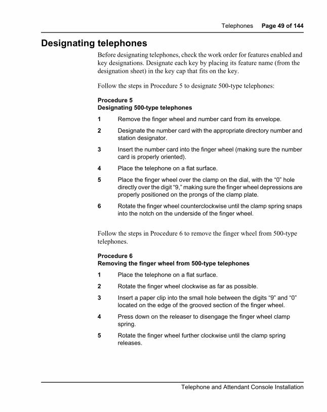
Designating telephonesBefore designating telephones, check the work order for features enabled andkey designations. Designate each key by placing its feature name (from thedesignation sheet) in the key cap that fits on the key.
Follow the steps in Procedure 5 to designate 500-type telephones:
Procedure 5Designating 500-type telephones
1 Remove the finger wheel and number card from its envelope.
2 Designate the number card with the appropriate directory number andstation designator.
3 Insert the number card into the finger wheel (making sure the numbercard is properly oriented).
4 Place the telephone on a flat surface.
5 Place the finger wheel over the clamp on the dial, with the “0” holedirectly over the digit “9,” making sure the finger wheel depressions areproperly positioned on the prongs of the clamp plate.
6 Rotate the finger wheel counterclockwise until the clamp spring snapsinto the notch on the underside of the finger wheel.
Follow the steps in Procedure 6 to remove the finger wheel from 500-typetelephones.
Procedure 6Removing the finger wheel from 500-type telephones
1 Place the telephone on a flat surface.
2 Rotate the finger wheel clockwise as far as possible.
3 Insert a paper clip into the small hole between the digits “9” and “0”located on the edge of the grooved section of the finger wheel.
4 Press down on the releaser to disengage the finger wheel clampspring.
5 Rotate the finger wheel further clockwise until the clamp springreleases.
Telephone and Attendant Console Installation

Page 50 of 144 Telephones
6 Remove the finger wheel when it becomes loose. The dial returns tonormal position.
Procedure 7Designating 2500-type telephones
1 The designation window is located directly below the dial pad. Insert apaper clip into the hole at the left or right end of the designationwindow.
2 Gently pry the window toward the center and remove.
3 Insert number tag with the appropriate directory number and stationdesignator, and replace the designation window.
Procedure 8Designating M2000 Series Meridian Digital Telephones
1 Remove the cap from each key requiring a designation.
2 Place the designation in the cap, place the cap over the correspondingkey, and gently press down. Repeat for all keys requiring designations.
3 Insert a paper clip into the hole at the left or right end of the designationwindow.
4 Gently pry the window toward the center and remove, and insert thenumber tag.
5 Replace the designation window.
553-3001-215 Standard 12.00 January 2002

Telephones Page 51 of 144
Connecting telephonesProcedure 9 describes how to connect 500- and 2500-type telephones.
Table 10 lists the NE-500/2500 telephone connections.
Procedure 9Connecting 500/2500-type telephones
1 Ensure that the terminal connector is compatible with the telephoneconnector.
2 Connect the telephone mounting cord.
TELADAPT cords (NE-625F connector) do not require terminations.Insert the plastic connector on the end of the telephone mounting cordinto the NE-625F-type receptacle.
3 Connect the mounting cord to an NE-284-74-5001 Amphenol adapterif reusing a 16- or 25-pair cable. Plug the adapter into the cableconnector. Fasten the connector together with the screws provided atthe end of each connector.
Table 10NE-500/2500 telephone connections
Mountingcord
NE-47QAor
QBBIB blockdesignation
NE-284-74-5001designation
Cable colorpairs
(16 to 25 notused)
Connectto TN
TIP (green) G 1T W-BL TIP
RING (red) R 1R BL-W RING
GND (yellow) BK X2
Y X1
Telephone and Attendant Console Installation

Page 52 of 144 Telephones
Cross-connecting telephonesBe sure to connect the telephones according to Figures 14 or 15. Figure 14 onpage 53 provides the diagram for cross-connecting analog (500/2500-type)telephones on a peripheral equipment (PE) module. Tables 11, 12, and 13show analog (500/2500-type) telephone cross-connections on an IntelligentPeripheral Equipment (IPE) module.
Cross-connections for the M2000 Series Meridian Digital Telephone areshown in Figure 15 on page 58.
Procedure 10Cross-connecting telephones
1 Locate the telephone terminations at the cross-connect terminal.
Telephone terminations are located on the vertical side of the framewhen frame-mounted blocks are used and in the blue field whenwall-mounted blocks are used.
2 Connect Z-type cross-connecting wire to the leads of the telephone.See Table 14 on page 57 and on page 57.
3 Locate the line circuit card (TN) terminations.
Line circuit card (TN) terminations are located on the horizontal side ofthe distributing frame when frame-mounted blocks are used and in thewhite field when wall-mounted blocks are used.
4 Run and connect the other end of the cross-connecting wire to theassigned TN terminal block.
553-3001-215 Standard 12.00 January 2002
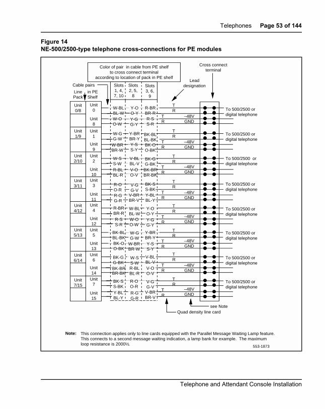
Telephones Page 53 of 144
Figure 14NE-500/2500-type telephone cross-connections for PE modules
Note: This connection applies only to line cards equipped with the Parallel Message Waiting Lamp feature.This connects to a second message waiting indication, a lamp bank for example. The maximum loop resistance is 2000½.
Slots1, 4,7, 10
Slots3, 6,
9
Slots2, 5,
8
Cable pairs
Color of pair in cable from PE shelfto cross connect terminal
according to location of pack in PE shelfLead
designation
Cross connectterminal
Quad density line cardsee Note
To 500/2500 ordigital telephone
To 500/2500 ordigital telephone
To 500/2500 ordigital telephone
To 500/2500 ordigital telephone
To 500/2500 ordigital telephone
To 500/2500 ordigital telephone
To 500/2500 ordigital telephone
To 500/2500 ordigital telephone
TR
TR
TR
TR
TR
TR
TR
TR
TR
TR
TR
TR
TR
TR
TR
TR
–48VGND
–48VGND
–48VGND
–48VGND
–48VGND
–48VGND
–48VGND
–48VGND
W-BLBL-WW-OO-W
W-GG-W
W-BRBR-W
W-SS-WR-BLBL-R
R-OO-RR-GG-R
R-BRBR-RR-SS-R
BK-BLBL-BKBK-OO-BK
BK-GG-BK
BR-BKBK-BR
BK-SS-BKY-BLBL-Y
BK-GG-BK
Y-BRBR-YY-SS-Y
V-BLBL-VV-OO-V
V-GG-V
V-BRBR-V
R-SS-R
R-BRBR-R
BK-BLBL-BKBK-OO-BK
BK-BRBR-BK
BK-SS-BKY-BLBL-Y
Y-OO-YY-GG-Y
Y-OO-YY-GG-Y
Y-BRBR-YY-SS-Y
V-BLBL-VV-OO-V
V-GG-V
V-BRBR-V
W-BLBL-WW-OO-W
W-GG-W
W-BRBR-W
R-OO-R
R-GG-R
R-BLBL-R
W-SS-W
Unit0/8
Unit1/9
Unit2/10
Unit3/11
Unit4/12
Unit5/13
Unit6/14
Unit7/15
Unit0
Unit8
Unit1
Unit9
Unit2
Unit10
Unit3
Unit11
Unit4
Unit12
Unit5
Unit13
Unit6
Unit14
Unit7
Unit15
LinePack
in PEShelf
553-1873
Telephone and Attendant Console Installation

Page 54 of 144 Telephones
Table 11500/2500 line card pair-terminations for IPE module connectors A, E, K, R
Pair Pins Pair colorI/O panel connectors Unit
A E K R 16/card
1T/1R 26/1 W-BL/BL-W slot 0 slot 4 slot 8 slot 12 0
2T/2R 27/2 W-O/O-W 1
3T/3R 28/3 W-G/G-W 2
4T/4R 29/4 W-BR/BR-W 3
5T/5R 30/5 W-S/S-W 4
6T/6R 31/6 R-BL/BL-R 5
7T/7R 32/7 R-O/O-R 6
8T/8R 33/8 R-G/G-R 7
9T/9R 34/9 R-BR/BR-R 8
10T/10R 35/10 R-S/S-R 9
11T/11R 36/11 BK-BL/BL-BK 10
12T/12R 37/12 BK-O/O-BK 11
13T/13R 38/13 BK-G/G-BK 12
14T/14R 39/14 BK-BR/BR-BK 13
15T/15R 40/15 BK-S/S-BK 14
16T/16R 41/16 Y-BL/BL-Y 15
553-3001-215 Standard 12.00 January 2002

Telephones Page 55 of 144
Table 12500/2500 line card pair-terminations for IPE module connectors B, F, L, S
Pair Pins Pair colorI/O panel connectors Unit
B F L S 16/card
1T/1R 26/1 W-BL/BL-W slot 1 slot 5 slot 9 slot 13 0
2T/2R 27/2 W-O/O-W 1
3T/3R 28/3 W-G/G-W 2
4T/4R 29/4 W-BR/BR-W 3
5T/5R 30/5 W-S/S-W 4
6T/6R 31/6 R-BL/BL-R 5
7T/7R 32/7 R-O/O-R 6
8T/8R 33/8 R-G/G-R 7
9T/9R 34/9 R-BR/BR-R 8
10T/10R 35/10 R-S/S-R 9
11T/11R 36/11 BK-BL/BL-BK 10
12T/12R 37/12 BK-O/O-BK 11
13T/13R 38/13 BK-G/G-BK 12
14T/14R 39/14 BK-BR/BR-BK 13
15T/15R 40/15 BK-S/S-BK 14
16T/16R 41/16 Y-BL/BL-Y 15
17T/17R 42/17 Y-O/O-Y slot 2 slot 6 slot 10 slot 14 0
18T/18R 43/18 Y-G/G-Y 1
19T/19R 44/19 Y-BR/BR-Y 2
20T/20R 45/20 Y-S/S-Y 3
21T/21R 46/21 V-BL/BL-V 4
22T/22R 47/22 V-O/O-V 5
23T/23R 48/23 V-G/G-V 6
24T/24R 49/24 V-BR/BR-V 7
25T/25R 50/25 V-S/S-V Spare
Telephone and Attendant Console Installation

Page 56 of 144 Telephones
Table 13500/2500 line card pair-terminations for IPE module connectors C, G, M, T
Pair Pins Pair colorI/O panel connectors Unit
C G M T 16/card
1T/1R 26/1 W-BL/BL-W slot 2 slot 6 slot 10 slot 14 8
2T/2R 27/2 W-O/O-W 9
3T/3R 28/3 W-G/G-W 10
4T/4R 29/4 W-BR/BR-W 11
5T/5R 30/5 W-S/S-W 12
6T/6R 31/6 R-BL/BL-R 13
7T/7R 32/7 R-O/O-R 14
8T/8R 33/8 R-G/G-R 15
9T/9R 34/9 R-BR/BR-R slot 2 slot 6 slot 11 slot 15 0
10T/10R 35/10 R-S/S-R 1
11T/11R 36/11 BK-BL/BL-BK 2
12T/12R 37/12 BK-O/O-BK 3
13T/13R 38/13 BK-G/G-BK 4
14T/14R 39/14 BK-BR/BR-BK 5
15T/15R 40/15 BK-S/S-BK 6
16T/16R 41/16 Y-BL/BL-Y 7
17T/17R 42/17 Y-O/O-Y 8
18T/18R 43/18 Y-G/G-Y 9
19T/19R 44/19 Y-BR/BR-Y 10
20T/20R 45/20 Y-S/S-Y 11
21T/21R 46/21 V-BL/BL-V 12
22T/22R 47/22 V-O/O-V 13
23T/23R 48/23 V-G/G-V 14
24T/24R 49/24 V-BR/BR-V 15
25T/25R 50/25 V-S/S-V Spare
553-3001-215 Standard 12.00 January 2002

Telephones Page 57 of 144
Table 14Z-typecross-connecting wire
Size Gauge Color Designation
1 pr 22 Y-BL
BL-Y
Tip
Ring
3 pr 24 W-BL
BL-W
W-O
O-W
W-G
G-W
Voice T
Voice R
Signal T
Signal R
Power
Power
Table 15Inside wiring colors
Inside wiring colorsConnect to
equipment TNZ station wire 16/25-pair cable
G W-BL First pair Tip
R BL-W First pair Ring
BK W-O Second pair Tip
Y O-W Second pair Ring
Telephone and Attendant Console Installation

Page 58 of 144 Telephones
Figure 15M2000 Series Meridian Digital Telephone cross-connections
Unit 0
Unit 1
Unit 6
Unit 7
T0R0
T1R1
T6R6
T7
R7
261
283
3813
4016
W-BLBL-W
W-GG-W
BK-GG-BK
BK-S
S-BK
T0R0
T1R1
T6R6
T7
R7
GR
WB
Line cordto telephoneFor PowerSupply leads
to telephone
to telephone
to telephone
PE shelfLinePack
Packconnector
Part of25 pair cable
Shelf connector
Part of 25pair cable
Cross connectblock
Telephone connecting
block, or connector
553-1885
553-3001-215 Standard 12.00 January 2002

Page 59 of 144
134
Add-on modulesContents
This section contains information on the following topics:
Packing and unpacking. .. . . . . . . . . . . . . . . . . . . . . . . . . . . . . . . . . . . . 60Busy Lamp Field/Console Graphics Module. . . . . . . . . . . . . . . . . . 61
Attendant Supervisory Module (M2250 console). . . . . . . . . . . . . . . . . 72M2317 Data Option. . . . . . . . . . . . . . . . . . . . . . . . . . . . . . . . . . . . . . 75
M2000 Series Meridian Digital Telephones. . . . . . . . . . . . . . . . . . . . . 78
Analog Terminal Adapter. .. . . . . . . . . . . . . . . . . . . . . . . . . . . . . . . . . . 80Functional description . . . . . . . . . . . . . . . . . . . . . . . . . . . . . . . . . . . 80Meridian Communications Adapter and Meridian Programmable DataAdapter. . . . . . . . . . . . . . . . . . . . . . . . . . . . . . . . . . . . . . . . . . . . . . . 86Power Supply Board (NTZK models). . . . . . . . . . . . . . . . . . . . . . . . 93Power Supply Board (NT2K models). . . . . . . . . . . . . . . . . . . . . . . . 101Installing Displays . . . . . . . . . . . . . . . . . . . . . . . . . . . . . . . . . . . . . . 104Installing NT2K24WA or NT2K25YL displays on NTZK sets. . . . 105Installing NT2K28AA displays on NTZK or NT2K sets. . . . . . . . . 111Installing NT2K24WA or NT2K25YL displays on NT2K sets. . . . 116External Alerter Board. . . . . . . . . . . . . . . . . . . . . . . . . . . . . . . . . . . 121Key Expansion Modules .. . . . . . . . . . . . . . . . . . . . . . . . . . . . . . . . . 125Wall mounting. . . . . . . . . . . . . . . . . . . . . . . . . . . . . . . . . . . . . . . . . . 128Troubleshooting. .. . . . . . . . . . . . . . . . . . . . . . . . . . . . . . . . . . . . . . . 129
Reference listThe following are the references in this section:
• Analog Terminal Adapter Installation and Reference Card
Telephone and Attendant Console Installation
Page 60 of 144 Add-on modules
• M1250/M2250 Attendant Console User Guide
• Busy Lamp Field/Console Graphics Module User Guide
• Attendant Consoles: Description (553-2201-117)
• Meridian 1 Telephones: Description and Specifications (553-3001-108)
• Features and Services (553-3001-306)
Packing and unpackingUse proper care while unpacking any add-on module. Check for damagedcontainers so that appropriate claims can be made to the transport companyfor items damaged in transit.
If a module must be returned to the factory, pack it in the appropriatecontainer to avoid damage during transit. Remember to include all loose partsin the shipment.
Note: There are three distinct versions of M2000 Series MeridianDigital Telephones – all three are supported. The versions can be clearlydistinguished by the first four letters in the upper left-hand corner of themodel identification label on the bottom of the telephone.
The three versions are as follows:
• the “NTZK” models,
• the “NT2K” models with date code prior to April 24, 1998
• the third version includes both the “NT9K” models and the “NT2K”models with date code of April 24, 1998 and later
In addition, the two jacks face in the same direction on “NT2K” and“NT9K” telephones, and in opposite directions on “NTZK” telephones.When appropriate, differences between the models are noted in thisdocument.
553-3001-215 Standard 12.00 January 2002

Add-on modules Page 61 of 144
Busy Lamp Field/Console Graphics ModuleThe Busy Lamp Field/Console Graphics Module (BLF/CGM) obtains itspower through the attendant console. See Figure 16. The requirements are asfollows:
• a reference ground line (0 V)
• power source of 5 V for the CMOS electronics that control the LampField Array module (c. 50 mA)
• power source of –12 V for the display of the Console Graphics Module(c. 10 mA)
• backlighting power
An external floating 16 V dc (300 mA) power supply is required to be cabledin at the local Main Distribution Frame (MDF) at a maximum of 120 ft (36 m)from the attendant console when the BLF/CGM is installed (A0367601 –Transformer). This provides all the power requirements for the M2250applications.
The BLF/CGM has a battery that provides backup power to maintain theSupplementary Information when the console is powered down. The batterylifetime is 5 years. To replace the battery, return the BLF/CGM to yoursupplier.
The BLF/CGM mounts on the back of the attendant console and is held onwith snapfits and two screws.
The attendant console’s top cover must be removed to install the BLF/CGM.
Refer to theM1250/M2250 Attendant Console User Guide or the Busy LampField/Console Graphics Module User Guide for further information. Refer toAttendant Consoles: Description (553-2201-117) for a description of M2250attendant consoles equipped with a BLF/CGM.
Follow normal anti-static precautions when installing the BLF/CGMonto theattendant console.
Telephone and Attendant Console Installation
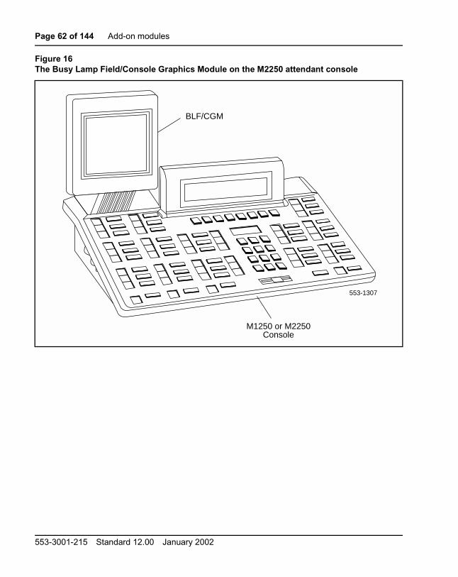
Page 62 of 144 Add-on modules
Figure 16The Busy Lamp Field/Console Graphics Module on the M2250 attendant console
BLF/CGM
M1250 or M2250Console
553-1307
553-3001-215 Standard 12.00 January 2002

Add-on modules Page 63 of 144
Procedure 1Connecting the BLF/CGM to M2250 attendant consoles
1 Disconnect themain power/system cable from the rear of the attendantconsole, and remove the handset jack plug from the side.
2 Move the adjustable display to the down position to protect it fromdamage while installing the Busy Lamp Field/Console GraphicsModule (BLF/CGM). Also move the volume slider switch to the far left(see Figure 17).
3 Place the attendant console facedown on a properly prepared worksurface, taking care to avoid scratching or damaging the top cover ordisplay. Remove the adjustable stand, if required.
The stand is secured with four screws. Remove the stand as acomplete assembly, and set aside.
4 Remove the 12 fastening screws in the base of the attendant consolethat secure the top cover to the console base. See Figure 18 onpage 64. Holding the console base and cover firmly, turn it over so thatthe top cover is on, facing up.
5 Raise and hold the top cover to remove the single cable connectoronly. The alerter cable does not need to be removed. See Figure 19on page 65.
Figure 17Volume slider position
Move Volume Sliderto left-most position
553-1892
Telephone and Attendant Console Installation

Page 64 of 144 Add-on modules
6 Remove the top cover and place it upside down to the left of theattendant console.
7 Remove the knockout section on the back of the attendant console(see Figure 20 on page 66) with a small screwdriver or similar tool.Remove any remnants of the breakaway tags.
8 Feed the flat ribbon cable for the Busy Lamp Field/Console GraphicsModule (BLF/CGM) through the knockout hole in the base of theattendant console.
9 Hold the BLF/CGMunit over the console in a vertical position, ensuringthat the two locators on the bottom bracket of the BLF/CGM arelocated in the knockout hole.
10 Push down on the attendant console, while holding the BLF/CGM unit,until the two locators snap into place. See Figure 21 on page 67.
Figure 18Removing the fastening screws
Do Not RemoveThese Screws
Do Not RemoveThese Screws
Remove These12 Screws
PolystyreneFoam Sheet
553-1890
553-3001-215 Standard 12.00 January 2002

Add-on modules Page 65 of 144
11 Fit the BLF/CGM ribbon cable onto the top cover circuit board, into theflexible strip connector J4 (so that the blue line on the cable faces awayfrom the circuit board).
12 Hold the top cover over the attendant console and reconnect the cableconnector(s) onto the base of the attendant console.
13 Place the top cover on the console. Slide it back and down into place.See Figure 23 on page 69. Check that all the cables are in the correctpositions and that none are trapped.
14 Push the BLF/CGM display into position by rotating it back (seeFigure 23).
15 Ensuring that the volume slider is fully engaged in the correct slider,hold the top cover and console base firmly together. Turn the assemblyupside down. See Figure 24 on page 70.
Figure 19Removing the top cover
On M1250 models remove a) Flat cables (2 places) b) Alerter connector
On M2250 modelsremove flat cable
Top cover
553-1308
Base
Telephone and Attendant Console Installation

Page 66 of 144 Add-on modules
16 Reinsert the 12 screws that secure the top cover to the console baseand tighten.
17 Insert the two new screws supplied with the BLF/CGM that attach it tothe base, and tighten. See Figure 24 on page 70.
18 Cable in BLF power at the local Main Distribution Frame (MDF) as perM2250 cross-connections. See Procedure 1 on page 18.
19 If required, replace the adjustable stand.
20 Reconnect the main system cable to the rear of the console.
21 If the BLF/CGM has been correctly installed, the main menu appearswhen power is supplied to the attendant console. Test the BLF/CGMby selecting a menu option. Refer to Busy Lamp Field/ConsoleGraphics Module User Guide for programming information.
22 Define the Busy Lamp Field in the system database. Refer to Featuresand Services (553-3001-306).
23 Test the Busy Lamp Field features using M1250/M2250 AttendantConsole User Guide.
Figure 20Attendant console knockout section
Base
Knockout Section(Clean Away 6 Tags)
553-1893
553-3001-215 Standard 12.00 January 2002

Add-on modules Page 67 of 144
Figure 21Connecting the BLF/CGM to the attendant console
BLF/CGM Flat cable
BLF/CGM
Base553-1309
Telephone and Attendant Console Installation

Page 68 of 144 Add-on modules
Figure 22Support spacer
���
����
Top cover PCB
Boss on top cover
Support Spacer
Ensure that protrusionis located in slot
Base PCB
553-1310
553-3001-215 Standard 12.00 January 2002

Add-on modules Page 69 of 144
Figure 23Positioning the top cover and the BLF/CGM
Rotate Back
BLF/CGM
Top Cover
Base
Slide Backand Down
553-1894
Telephone and Attendant Console Installation

Page 70 of 144 Add-on modules
Figure 24Attaching the top cover to the attendant console base and BLF/CGM
Fit 2 new screws
Polystyrene foam sheet
553-1311
Re-Insert12 Screws
553-3001-215 Standard 12.00 January 2002

Add-on modules Page 71 of 144
Procedure 1Removing the Busy Lamp Field/Console Graphics Module
1 Disconnect themain power/system cable from the rear of the attendantconsole, and remove the handset jack plug from the side.
2 Move the adjustable display to the down position to protect it fromdamage while removing the BLF/CGM. Also move the volume sliderswitch to the far left (see Figure 17).
3 Place the attendant console facedown on a properly prepared worksurface, taking care to avoid scratching or damaging the top cover ordisplay. Remove the adjustable stand, if required.
The stand is secured with four screws. Remove the stand as acomplete assembly, and set it aside.
4 Remove the 12 fastening screws in the base of the attendant consolethat secure the top cover to the console base. See Figure 18 onpage 64.
Remove the two screws securing the BLF/CGM to the base of theattendant console.
5 Holding the console base and cover firmly, turn it back over so that thetop cover is on, facing up.
6 Raise and hold the top cover to remove the single cable connectoronly. The alerter cable does not need to be removed (see Figure 19).
7 Unplug the BLF/CGM ribbon cable from the attendant console.
8 Remove the top cover and place it upside down to the left of theattendant console.
9 Pull back the snap-fits on the BLF/CGM to disengage the BLF/CGMfrom the attendant console.
10 Place the top cover on the console. Slide it back and down into place(see Figure 23 on page 69). Reconnect all cables in the correctpositions, and make sure that none are trapped.
11 Ensuring that the volume slider is fully engaged in the correct slider,hold the top cover and console base firmly together. Turn the assemblyupside down (see Figure 24 page 70).
12 Reinsert the 12 screws that secure the top cover to the console baseand tighten.
13 If required, replace the adjustable stand.
Telephone and Attendant Console Installation

Page 72 of 144 Add-on modules
14 Reconnect the main system cable to the rear of the console.
Attendant Supervisory Module (M2250 console)The M2250 digital attendant console needs the Attendant SupervisoryModule (ASM) to allow supervision. The M2250 cannot be connected to aQPC297Attendant ConsoleMonitor circuit card.With theASM installed, theM2250 attendant console can be supervised just like any other attendantconsole. An M2250 attendant console configured as a supervisor does notneed the ASM installed.
To accept the ASM, the minimum vintage M2250 attendant console isM2250AD. To fully support the ASM, the minimum vintage BLF/CGM isAB. The third PWR TN must be programmed and wired out to support theASM. See Figure 9 on page 20.
Procedure 2Installing an Attendant Supervisory Module in an M2250attendant console
1 Disconnect themain power/system cable from the rear of the attendantconsole, and remove the handset jack plug from the side.
2 Move the adjustable display to the down position to protect it fromdamage while installing the ASM. Move the volume slider switch to theleft-most position.
3 Place the attendant console facedown on a properly prepared worksurface, taking care to avoid scratching or damaging the top cover ordisplay. Remove the adjustable stand, if equipped.
The stand is secured with four screws. Loosen the screws and removethe stand as a complete assembly, and set aside.
CAUTION WITH ESDS DEVICESDamage to Equipment
Before handling internal set components, dischargestatic electricity from hands and tools by touching anygrounded metal surface or conductor.
553-3001-215 Standard 12.00 January 2002

Add-on modules Page 73 of 144
4 Remove the 12 fastening screws in the base of the attendant consolethat secure the top cover to the console base (see Figure 18 onpage 64). Holding the console base and cover firmly, turn it back overso that the top cover is on, facing up.
5 Raise and hold the top cover to remove the single cable connector.The alerter cable does not need to be removed (see Figure 19 onpage 65). Remove the top cover and place it upside down to the left ofthe attendant console.
6 The attendant console’s main PCB has holes located in the upperright-hand side, near grid positions D1, D5, and A5. See Figure 25 onpage 74. Insert one standoff in each of the holes, twisting it until it issecure.
7 Position the ASM board over the J3 connector on the console’s mainPCB. Align the holes on the ASM board with the standoffs and carefullywork the ASM pin connector onto connector J3 until firmly seated. SeeFigure 25 on page 74.
8 Hold the top cover over the attendant console and reconnect the cableconnector onto the base of the console.
9 Place the top cover on the console. Slide it back and down into place.Check that all the cables are in the correct positions, and that none aretrapped.
10 Ensure that the volume switch is fully engaged in the correct slider.Hold the top cover and console base firmly together. Turn theassembly upside down.
11 Reinsert the 12 screws that secure the top cover to the console baseand tighten.
12 If required, replace the adjustable stand.
13 Reconnect the main system cable to the rear of the console.
CAUTIONDamage to Equipment
Once a standoff is inserted, it cannot be removed. Besure to place each standoff in the correct hole on themain PCB, as shown in Figure 25 on page 74.
Telephone and Attendant Console Installation

Page 74 of 144 Add-on modules
14 Test the supervisory console feature to make sure you can nowproperly supervise the M2250 attendant console. Refer toM1250/M2250 Attendant Console User Guide.
Figure 25Identifying the correct grid positions on the main PCB and attaching the ASM
59
A
B
C
D
Grid marks
Insert Standoffs here
Attendant Supervisory Module
Pin connector
M2250 main PCB (cutaway)
J3 connector
553-5113
553-3001-215 Standard 12.00 January 2002

Add-on modules Page 75 of 144
M2317 Data OptionIf an existing digital telephone was not originally equipped with the DataOption, or if the existing Data Option has become defective, that option canbe added or replaced. The following procedure explains how to install theData Option for the M2317 telephone.
1 Remove the handset, and place the telephone upside down on a levelworkplace (a desktop, for example).
2 Disconnect all cords from the telephone.
3 Loosen and remove five screws in the base of the telephone, lifting thebase upward.
4 If the telephone is not equipped with the ADO, proceed with step 5.
If the telephone is equipped with a defective ADO, carefully disconnectthe ribbon cable connector from the header connector in the digitalprinted circuit board. Loosen and remove the two self-tapping screwsthat fasten the ADO to the telephone base and remove the defectiveADO. Proceed with step 6. See Figure 26 on page 77.
5 Remove the breakout section in the rear of the telephone base bytapping it with the handle of a small screwdriver.
6 Place the black plastic connector shroud over the RS-232-C interfaceconnector.
Note: It is not possible to install the shroud after the board has beeninserted in the telephone base.
7 Tip the circuit board up and insert it, connector end first, under the tabsin the base. Position it over the molded locating pins; then lower theboard completely into position in the telephone base. Use the threeslotted, self-tapping screws supplied with the board and install themthrough the mounting holes. Tighten the screws.
CAUTION WITH ESDS DEVICESCMOS devices inside the telephone can be damagedby electrostatic discharge. Before opening anyM2317 telephone, discharge your hands and tools bytouching any grounded metal surface or conductor.
Telephone and Attendant Console Installation

Page 76 of 144 Add-on modules
8 Plug the ribbon cable connector into the header connector, located onthe existing circuit board of the telephone (mounted on the faceplateassembly). There is only one such connector on the telephone’s circuitboard. Make sure the connector is snug.
9 Reassemble the telephone by placing the base section on thefaceplate section. Reinstall the five screws.
10 Tighten the screws, reconnect all cords, and place the telephone in itsformer position.
11 Refer to Procedure 1 to connect the power supply and data terminal tothe ADO.
Procedure 1Installing the M2317 data terminal
1 Connect the RS-232-C interface connector from the data terminal tothe matching header connector in the back of the telephone. SeeFigure 26 on page 77.
2 Insert the two captive screws in the connector body into the threadedholes in the header connector. Secure them tightly to preventaccidental disconnection during data terminal operation.
3 Insert the keyed power supply plug securely into the 5-pin powerconnector located to the right of the RS-232-C connector.
4 Plug the wall transformer into the nearest ac outlet. The data terminalis now operational.
Note 1: If an ADM3, ADM5, or ADM11 terminal is used in conjunctionwith the RS-232-C connector in the Asynchronous Data Option, pin 22in the RS-232-C cable must be disconnected. These ADM terminalswill go into test mode if this pin is not disconnected.
Note 2: A special 9-pin connector is required to connect the AppleMacintosh to the RS-232-C connector in the M2000 AsynchronousData Option. The connections are shown in Table 16 on page 77.
553-3001-215 Standard 12.00 January 2002
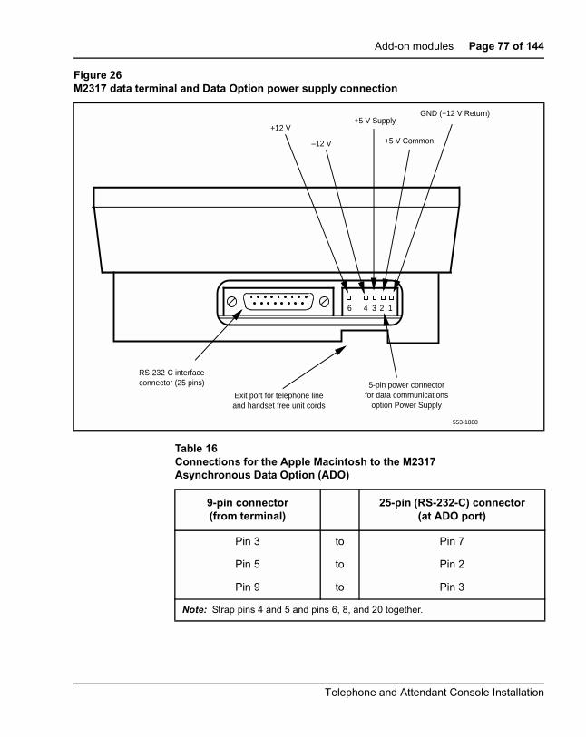
Add-on modules Page 77 of 144
Figure 26M2317 data terminal and Data Option power supply connection
Table 16Connections for the Apple Macintosh to the M2317Asynchronous Data Option (ADO)
9-pin connector(from terminal)
25-pin (RS-232-C) connector(at ADO port)
Pin 3 to Pin 7
Pin 5 to Pin 2
Pin 9 to Pin 3
Note: Strap pins 4 and 5 and pins 6, 8, and 20 together.
12346
RS-232-C interfaceconnector (25 pins)
Exit port for telephone lineand handset free unit cords
5-pin power connectorfor data communications
option Power Supply
+12 V
–12 V
+5 V Supply
+5 V Common
GND (+12 V Return)
553-1888
Telephone and Attendant Console Installation

Page 78 of 144 Add-on modules
M2000 Series Meridian Digital TelephonesUse the procedures in this section for adding hardware options to the M2006,M2008/M2008HF, M2016S, M2616, and M2216ACD sets only.
Figure 27 on page 79 shows an exploded view for reference whendismantling the telephone to get to its internal components. Some telephonetypes are slightly smaller than the M2616 and do not have the center screw inthe base, but otherwise they are the same. The center screw may not berequired.
Table 17RS-232-C signals and associated pin numbers for M2317 telephones
Circuit designation Pinnumber
Signal source
EIA Common CCITT DTE DCE Name
AA 101 1 X Frame ground
BA TXD 103 2 X Transmit data
BB RXD 104 3 X Receive data
CA RTS 105 4 X Request to send
CB CTS 106 5 X Clear to send
CC DSR 107 6 X Data set ready
AB GND 102 7 X Signal ground
CD DTR 108.2 20 X Data terminal ready
CE RI 125 22 X Ring indicator
CAUTIONDamage to EquipmentUse only the line cord provided with the M2000Series Meridian Digital Telephone when installingand removing options. The acceptable line cord isA0346862.
553-3001-215 Standard 12.00 January 2002

Add-on modules Page 79 of 144
Refer to Figure 31 on page 95 to locate the various components of theM2006and M2008/M2008HF telephones. Refer to Figure 32 on page 96 to locatecomponents on the M2616, M2016S, and M2216ACD telephones.
Figure 27Exploded view of the M2616/M2016S/M2216ACD telephone
Stand
Base
Set
Fillerplate
553-1846
Telephone and Attendant Console Installation
Page 80 of 144 Add-on modules
Analog Terminal AdapterThe Analog Terminal Adapter (ATA) allows the use of an off-the-shelfanalog device (FAX, Modem, Telephone) to operate simultaneously with aMeridian Digital Telephone. The Analog Terminal Adapter board fits into thefootstand space of the Meridian Digital Telephone.
Functional descriptionThe Analog Terminal Adapter is compatible with theM2000 SeriesMeridianDigital Telephone set. It is mounted in the redesigned footstand of theM2000Series Meridian Digital Telephone. The M2000 Series Meridian DigitalTelephone’s (M2006/8 and M22/2616) footstand is modified toaccommodate the ATA. The ATA requires a separate ac adapter whichprovides a 24 volt ac external power source. The ATA does not draw powerfrom the M2000 Series Meridian Digital Telephone.
The Analog Terminal Adapter (ATA) provides a RJ11 connection for analogequipment to operate on the same line as the M2000 Series Meridian DigitalTelephone set. The Analog Terminal Adapter allows data to be transmittedand received using the Public Switched Telephone Network (PSTN). TheATA supports an analog device link to the desktop or laptop computer users(with modems) in the digital telephone environment. Currently, it isnecessary to install a separate analog phone line to be able to interface withthe PSTN.
The ATA can be used for the following analog devices:
• FAX machine
• modem
• analog (500/2500-type) telephone
ATA operating parametersThe ATA data parameters are stored locally although the configuration is setin the system. Data parameters must be set in the system after installing theATA in the telephone. If the parameters are set before the telephone isinstalled, the configuration information will be lost.
553-3001-215 Standard 12.00 January 2002

Add-on modules Page 81 of 144
Simultaneous voice, FAX/modem calls require the Flexible Voice/DataTerminal Number feature. LD 11 is configured in the system whenimplementing the Flexible Voice and Data Feature. See the SoftwareInput/Output Guide Administration (553-3001-311) for prompt and responsedetails.
The Analog Terminal Adapter (ATA) is capable of receiving dial pulse orDTMF address signaling from the analog equipment.
The ATA uses the 2nd channel of the TCM loop to add an analog port to thedigital terminal. It has an RJ11 type jack accessible from the back of thetelset.
The analog interface of the ATA is a 2-wire source, providing A and B leads(tip and ring) across which analog equipment (modem/fax) is connected. Theloop length will be >100 feet. The analog interface of the ATA is compatiblewith the port types listed in Table 18.
Refer to Analog Terminal Adapter Installation and Reference Card fordetailed information on this feature.
Follow the steps in Procedure 1 on page 82 to add the Analog TerminalAdapter (ATA) to the telephone and to connect it to a FAX or modem. TheATA is supported on Meridian Digital Telephones only.
Table 18Port types compatible with ATA
County Port Type(s)Defining
Standard(s)
UnitedStates
ONS Station InterfaceClass A OPS Station Interface
EIA/Tia-464AFCC Rules Part 68
Canada ONS Station InterfaceClass 1300 OPS Station Interface
CAN3-T512.1CS-03 Part I
Telephone and Attendant Console Installation

Page 82 of 144 Add-on modules
Procedure 1Installing and removing the Analog Terminal Adapter
1 When the ATA is installed, the System Administrator must activate theFlexible Voice and Data Feature by configuring LD 11.
2 To Activate the Flexible Voice and Data Feature, use the followingchart to configure LD 11 (for more detailed information, refer toSoftware Input/Output Guide Administration (553-3001-311)).
3 Disconnect and remove all cords (including the handset cord) from thetelephone.
CAUTION WITH ESDS DEVICESBefore handling internal telephone components,discharge static electricity from hands and tools bytouching any grounded metal surface or conductor.
Table 19:Flexible Voice and Data feature configuration
Prompt Response Description
REQ: NEW/CHG New, or change
TYPE: aaaa Telephone type, whereaaaa=2006,2008, 2016, or 2616
TN Iscu Terminal Number where u=16-31
CLS FLXA Flexible voice/data allowed. This Class of service can only beassigned to 2006, 2008, 2016, 2216 or 2617 sets. When configuredto CLS=FLXA
VCE (FLXD) = Flexible voice/data denied. Voice Class of Service (VCE)can be assigned to the upper TN unit (16-31) and Data class ofService (DTA) can be assigned to the lower TN (0-15). A Single CallRinging (SCR) key can be designated a Data Mode (DTNK) key.
KEY Prime Directory Number Key, SCR, SCN, MCR or MCN and xxx.
-Key xxSCRyyyy Single Call Ringing
xxSCNyyyy Single Call Non Ringing Data Mode Key, where xx=key number andyyy=Data Directory Number.
553-3001-215 Standard 12.00 January 2002

Add-on modules Page 83 of 144
4 Place the telephone, face-down, on a padded level surface.
5 Using a #1 Phillips screw driver, remove both screws and separate thefootstand from the phone base.
6 If using the NT9K ATA ready set or the NT2K with date code of April24, 1998 or later:
• Remove and retain the footstand (this footstand will bereattached back onto the set base after ATA installation iscomplete.
• Skip to the ATA Installation Procedure 13 on page 86.
7 If using the NT2K or the NTZK phone set, remove and discard thefootstand. Use the redesigned footstand required for the installation ofthe ATA.
8 If an MCA or MPDA installed is installed, unplug it from the data linejack in the phone base.
9 Remove the back covering of the phone base by removing the fourscrews.
Figure 28Telephone base and footstand
Footstand
Telephone and Attendant Console Installation

Page 84 of 144 Add-on modules
10 If the phone is equipped with a Power Option board and/or cable, youmust remove it before installing the ATA. The Power Option board islocated on the left side of the telephone:
• Remove the two small screws from the Power Option board(near the top) and set them aside.
• To disconnect the Power Option board from the NTZKtelephone, grasp the board firmly on each side and slowly rockthe Power Option board while applying upward pressure until itis released form the 2X7 pin connector.
• To disconnect the NT2K Power Option board from the setsimply remove the screws from the Power Option board andbase and lift the board out of the set.
• If the Power Option board has a ribbon cable, disconnect thecable from the 2X7pin connector on the main board andremove the cable
553-3001-215 Standard 12.00 January 2002

Add-on modules Page 85 of 144
Figure 29Connector view
11 If the phone is equipped with the External Alerter Option, remove itbefore installing the ATA. The External Alerter Option board is locatedat the right center of the telephone:
• Remove the screws from the External Alerter Option board.
• Grasp the board firmly on each end and pull upward to removefrom the 2X3 pin connector
12 Install the Jumper board on the 2X7 pin connector inside the phone setbase.
• There are 2 Jumper boards provided. Use the brown Jumperboard for the NTZKxxxx phone set and the black Jumper boardfor the NT2Kxxxx phone set with a date code prior toApril 24, 1998.
• If a Power Option board was not installed on the NT2Kxxxx andthe NTZKxxxx there will be 2 Jumper plugs on the 2X7 pinconnector that must be removed before installing the Jumperboard.
Display board
Power board
Alerter board
2x3 pin connector
2x7 pin connector
Inside Phone Base
Telephone and Attendant Console Installation

Page 86 of 144 Add-on modules
13 Remove the knockout located on the back panel of the footstand inorder to install the ATA. It is the smaller knockout, located inside thelarge knockout. The small ATA knockout can be remove by pressing itin with thumb presser.
14 Install the ATA Printed Circuit board into the footstand.
15 Plug the ATA 8-conductor line cord, included in the package, into thedata jack in the base of the telephone. Plug the other end of this cordinto the data jack of the ATA located in the footstand.
16 Reassemble the footstand on the base and screw it into position usinga #1 Phillips screwdriver.
17 Plug the 24v AC Power Transformer into the circular mini DINconnector on the backpanel of the footstand.
18 Plug the transformer end of the AC Power Transformer into the ACcommercial electrical outlet.
19 The analog device can now be connected to the RJ11 connector onthe back of the footstand. Refer to the manufacturer’s documentationfor installation instructions for the FAX, modem, or telephone to beused.
Meridian Communications Adapter and MeridianProgrammable Data Adapter
TheMeridian Communications Adapter (MCA) mounts within the telephoneand allows asynchronous and synchronous ASCII terminals, and personalcomputers to be connected to the telephone using an RS-232C or V.35interface on a DB-25 connector. The MCA replaces the MeridianProgrammable Data Adapter (MPDA). Data programming can beimplemented on the MCA through a service change (LD11) as well as thekeypad.
Use the following procedures to add the Meridian Communications Adapter(MCA) or Meridian Programmable Data Adapter (MPDA) to the telephoneand to connect it to a terminal or personal computer.
When using the MCA for synchronous data connections, configure thetelephone with a display option to view the data parameters. The MPDA andMCA are supported on M2000 Series Meridian Digital Telephones only.
553-3001-215 Standard 12.00 January 2002

Add-on modules Page 87 of 144
Installing an MCA or MPDA to NTZK or NT2K phone sets with date codeprior to April 24, 1998 requires the installation of a Power Option board alongwith an additional power source.
When installing an MCA in an NT9K phone set, or an NT2K with date codeof April 24, 1998 and later, install only theMCA (an additional Power Optionboard and Jumper board is not required).
• See Procedure 2 on page 93 for M2006/M2008 NTZK sets.
• See Procedure 13 on page 95 for M2616/M2216ACD NTZK sets.
• See Procedure 1 on page 101 for M2006/M2008/M2008HF NT2K sets.
• See Procedure 1 on page 82 for installing an MCA onto an NT9K orNT2K with date code of April 24, 1998 and later.
The MCA can be placed as far from its associated data terminal or computerport as is consistent with EIA RS-232 or V.35.
When the MCA is used as a V.35 interface, an additional cable is required toconvert the DB-25 into a 34-pin rectangular connector. This does not applyto asynchronous configurations. If the pins are left in V.35 mode,asynchronous operation is not supported, and the MCA looks as though it islocked up.
Remove the two 14-pin jumper plugs or one 20-pin jumper plug inside theMCA from the RS-232 socket(s) and install the V.35 socket.
Note: The female cable ordering code is A0408927. The male cableordering code is A0408928. The A0300752 and A0300753 cables arestill supported, unless used with applications similar to IBM front-end.
Modem pooling is not supported on the MCA.
When a call is connected between two MCAs, and power is removed fromone, the MCA does not release until the power is restored.
The MCA always remembers the most recent data parameters. In the case ofpower failure, data settings do not have to be reset.
See Table 20 on page 88 for a listing of the V.35 CCITT signals supported bythe MCA.
Telephone and Attendant Console Installation

Page 88 of 144 Add-on modules
Table 20V.35 CCITT signals supported by the MCA (Part 1 of 2)
V.35CCITT
MCADB-25pin no.
Abbr.
Adaptor cableSignalSource
DescriptionDB-25Pin No.
V.35Pin No.
DTE MCA
101 1 DG 1 A Protective ground*
103A 2 SDA 2 P X Transmit data A
104A 3 RDA 3 R X Receive data A
105 4 RTS 4 C X Request to send
106 5 CTS 5 D X Clear to send
107 6 DSR 6 E X Data set ready
102 7 S 7 B Signal ground
109 8 CD 8 F X Carrier detect
— 9/10 — 9/10 CC/L No connection
— 11 — 11 K X **
115B 12 SCRB 12 X X Serial clock receive B
103B 13 SDB 13 S X Transmit data B
114B 14 SCTB 14 AA X Serial clock transmit B
114A 15 SCTA 15 Y X Serial clock transmit A
104B 16 RDB 16 T X Receive data B
115A 17 SCRA 17 V X Serial clock receive A
— 18/19 — 18/19 M/HH No connection
108.2 20 DTR 20 H X Data terminal ready
Note: * Pin 1 is connected to the MCDS shelf frame.** These leads are ignored by the MCA controller.
553-3001-215 Standard 12.00 January 2002

Add-on modules Page 89 of 144
Procedure 1Installing and removing the Meridian Communications Adapter orMeridian Programmable Data Adapter
If using a NT9K phone or the NT2K with date code of April 24, 1998 andlater, it is not necessary to install a Power Option board to operate the MCA.
1 Remove the handset and place the telephone upside down on top of alevel, solid work surface (a desktop, for example) covered with softmaterial or paper to prevent damage to movable keys and thetelephone face.
2 Disconnect all cords from the telephone.
— 21 — 21 EE No connection
125 22 RI 22 J X Ring indicator
113B 23 SCTEB 23 W X Tran sign elemt time B
113A 24 SCTEA 24 U X Tran sign elemt time A
— 25 — 25 MM X **
CAUTION WITH ESDS DEVICESBefore handling internal telephone components,discharge static electricity from hands and tools bytouching any grounded metal surface or conductor.
Table 20V.35 CCITT signals supported by the MCA (Part 2 of 2)
V.35CCITT
MCADB-25pin no.
Abbr.
Adaptor cableSignalSource
DescriptionDB-25Pin No.
V.35Pin No.
DTE MCA
Note: * Pin 1 is connected to the MCDS shelf frame.** These leads are ignored by the MCA controller.
Telephone and Attendant Console Installation

Page 90 of 144 Add-on modules
3 Remove the footstand.
• For NT2K and NTZK with date code prior to April 24, 1998remove the two screws from the footstand assembly andunsnap the footstand by pressing inward at the back of thefootstand where it meets the base and pull upward. Discard thefootstand. The redesigned footstand ordered with the ATA isused instead.
• For NT9K and NT2K with a date code of April 24, 1998 andlater, retain the footstand and skip to Procedure 10 onpage 91.
4 If the telephone is not equipped with the Meridian Programmable DataAdapter (MPDA) or Meridian Communications Adapter (MCA), go toProcedure 6 on page 90. If replacing an existing MPDA or MCA,carefully disconnect the end of the 8-pin TELADAPT jack plugged intothe telephone by pressing firmly on the latch-tab and slowly lifting up.
5 Turn the telephone footstand assembly over and put it in the normaluse position. Remove the two self-tapping screws that fasten theMPDA or MCA to the telephone footstand assembly and remove theMPDA or MCA by pulling outward and up. Go to Procedure 11 onpage 92 to replace the MPDA or MCA.
6 Remove the back covering of the phone base by removing the fourscrews.
7 If the NTZK or the NT2K (with date code prior to April 24, 1998) phoneset is equipped with a Power Option board and/or cable, the PowerOption board and/or cable must be removed before installing the MCA.
• Remove the two small screws from the Power board (near thetop) and set them aside.
• To disconnect the Power Option board from the NTZKtelephone, grasp the board firmly on each side and slowly rockthe board while applying upward pressure, until it is releasedfrom the 2X7 pin connector.
• To disconnect the NT2K Power Option board from the set,simply remove the screws from the base and lift the board outof the set.
• If the Power Option board has a ribbon cable disconnect thecable from the 2X7 pin connector on the main board andremove the cable.
553-3001-215 Standard 12.00 January 2002

Add-on modules Page 91 of 144
8 If the phone is equipped with the External Alerter board, it must beremoved before installing the MCA with redesigned footstand.
• The External Alerter board is located at the right center of thetelephone.
• Remove the screws form the board, grasp the board firmly oneach end and pull upward to remove it from the 2X3 pinconnector.
9 Install the Jumper board onto the 2X7 pin connector inside the phonebase.
• If the phone set did not have a Power Option board installed onthe NT2K or the NTZK then there will be 2 Jumper plugs on the2X7 connector. Remove them before installing the Jumperboard.
• The redesigned footstand will have 2 jumpers. Use the blackone for the NT2K phone and the brown one for the NTZKphone.
10 Remove the large MCA knockout section in the rear of the telephonefootstand assembly, and remove the small tabs. See Figure 30. It isbest to remove this knockout with a screwdriver.
Figure 30Installing the MCA
2
1MCABoard
553-6328
Telephone and Attendant Console Installation

Page 92 of 144 Add-on modules
11 For MCA, set option plugs to the required configuration, RS-232 orV.35. The factory default is RS-232.
12 Tilt the MPDA or MCA circuit board up and insert the DB-25 connectorsocket into the breakout section. Then slide the board connectorend-first under the tabs in the footstand assembly and position it overthe locating pins. Position and lower it completely onto the telephonefootstand assembly. Insert the two self-tapping Phillips-head screwssupplied with the MPDA or MCA into the mounting holes and tightenthem with a #1 Phillips screwdriver.
13 Plug one end of an 8-conductor line cord supplied with a TELADAPTadapter in the jack J1 of the MPDA or MCA (latch tab facing down) andplug the other end of the line cord into the data jack in the base of thetelephone. Make certain the latch tab of each cable end is firmlysnapped into place.
14 Carefully route the excess cable so that it will not become pinchedbetween the footstand and base.
15 Reassemble the base and footstand assembly sections, ensuring thatthe footstand is firmly seated on the base.
16 Tighten the screws
• Reconnect all cords, connect the new 24v AC transformer to theset.
• Plug in the new transformer into the 110v AC commercialelectrical outlet.
• Place the telephone in the normal operating position.
Note 1: Place the label supplied with the MPDA or MCA on theoutside of the bottom cover of the telephone. This allows properidentification and tracking of the option level of the set.
Note 2: If an ADM3, ADM5, or ADM11 terminal is used in conjunctionwith the DB-25 connector-C interface connector in the AsynchronousProgrammable Data Adapter, pin 22 in the DB-25 connector cablemust be disconnected. These ADM terminals will go into test mode ifthis pin is not disconnected.
553-3001-215 Standard 12.00 January 2002

Add-on modules Page 93 of 144
Procedure 1Connecting the data terminal
1 Connect the DB-25 connector-C interface connector from the dataterminal to the matching header connector in the back of thetelephone.
2 Insert the two captive screws in the connector body into the threadedholes in the header connector and secure tightly to prevent accidentaldisconnection during data terminal operation.
Power Supply Board (NTZK models)Use the following procedures to add a Power Supply Board to the telephonefor connection to a transformer or closet power supply. Use Procedure 2 forthe M2006 and M2008. USE Procedure 13 for the M2616, and M2216ACD.
Procedure 2Installing and removing the M2006/M2008Power Supply Board on NTZK sets
1 Remove the handset and place the telephone upside down on top of alevel, solid work surface (such as a desktop) covered with soft materialor paper to prevent damage to movable keys and the telephone face.
2 Disconnect all cords from the telephone.
CAUTIONDamage to EquipmentConnect the optional Power Supply to the M2000Series Meridian Digital Telephone only. Equipmentdamage may result from incorrect connections. Boththe closet power supply and the transformer are foruse with the M2000 Series Meridian DigitalTelephone only.
CAUTION WITH ESDS DEVICESBefore handling internal telephone components,discharge static electricity from hands and tools bytouching any grounded metal surface or conductor.
Telephone and Attendant Console Installation

Page 94 of 144 Add-on modules
3 Remove the two screws from the footstand assembly and unsnap thefootstand assembly by pressing inward at the back of the footstandwhere it meets the base and pulling upward.
4 If the telephone is equipped with a Meridian Programmable DataAdapter (MPDA) or Meridian Communications Adapter (MCA), unplugthe data cable from telephone’s base jack.
5 Remove the four screws securing the base of the telephone to the topcover. Remove the base and set it aside.
6 If the telephone is equipped with a display, disconnect the displayribbon cable from the display board and move it out of the way.
7 If the telephone is not equipped with the power supply board, removethe jumpers from P1 connector pins on the main board. Go to step 9.
If the telephone is equipped with a power supply board, go to step 8.
8 The power supply board is located on the left side of the telephone.Remove two small screws from the power supply board (near the top)and set them aside. Grasp the board firmly on each side. Work theboard loose from the connector by slowly applying upward pressure toalternate sides until released.
If the power supply board is not being replaced, place the jumpers(A0288529) connecting the bottom two sets of pins on the P1connector.
9 Place the power supply board so that the alignment pin on thetelephone fits into Slot A on the board. See Figure 31 on page 95 andFigure 32 on page 96. Align the mounting holes in the board (near thetop) over the mounting holes in the telephone and carefully press downso that the H1 connector on the board slides onto the P1 pins.
10 Take the self-tapping Phillips-head screws supplied with the powersupply board and install them into the mounting holes. Tighten firmlywith a #1 Phillips screwdriver.
11 If the telephone has a display, reconnect the display ribbon cable,routing the cable as described in Procedure 1 on page 105.
Note: Do not allow R5 on the power supply board to become bentduring this procedure.
553-3001-215 Standard 12.00 January 2002

Add-on modules Page 95 of 144
12 Replace the base. If the telephone is equipped with an MPDA or MCA,reconnect the data cable to the base telephone jack and replace thefootstand (ensuring that the MPDA or MCA cable does not get pinchedbetween the base and footstand). Make sure the footstand is firmlyseated to the base.
Note: Place the label supplied with the power supply board on theoutside of the bottom cover of the telephone. This allows properidentification and tracking of the option level of the set.
13 Tighten all screws, reconnect the line cord, and place the telephone inthe normal operating position.
Figure 31M2006/M2008 telephone and option boards
P1 connector
Display board
Slot A
Slot B
R5
H1 connector
P3 connectorP2 connector
J1 connector
J2 connector
H1 connector
553-1847
Power board
Alerter board
Telephone and Attendant Console Installation

Page 96 of 144 Add-on modules
Figure 32M2616/M2216ACD telephone and option boards
Power Board
Display Board
Alerter Board
P1 connector
P4 connector
P2 connector
H1 connector
H1 connector
J1 connector
J2 connector
Slot A
Slot B
R5
553-1848
553-3001-215 Standard 12.00 January 2002

Add-on modules Page 97 of 144
Procedure 1Installing and removing the M2616/M2216ACD Power Supply Board onNTZK sets
1 Remove the handset and place the telephone upside down on top of alevel, solid work surface (such as a desktop) covered with soft materialor paper to prevent damage to movable keys and the telephone face.
2 Disconnect all cords from the telephone.
3 Remove the two screws from the footstand assembly and unsnap thefootstand assembly by pressing inward at the back of the footstandwhere it meets the base and pulling upward.
4 If the telephone is equipped with an MPDA or MCA, unplug the datacable from the base telephone jack.
5 Remove the four or five screws securing the base to the top cover.Remove the base and set it aside.
6 If the telephone is equipped with display, disconnect the Display ribboncable from the display board and move it out of the way.
7 If the telephone is not equipped with a power supply board, removejumpers from the P1 connector pins on the main board. Go to step 9.
If the telephone is equipped with a power supply board, go to step 8.
8 The power supply board is located on the left side of the telephone.Remove two small screws from the power supply board (near the top)and set them aside. Grasp the board firmly on each side. Work theboard loose slowly until it is released.
If not replacing the power supply board, place the jumpers (A0288529)connecting the bottom two sets of the pins on the P1 connector.
9 Place the power supply board so that Slot B fits into the alignment pinon the telephone. See Figure 30 on page 91. Align the mounting holesin the board (near the top) over mounting holes in the telephone andcarefully press down so that the H1 connector on the board slides ontothe pins of the header (P1 on the M2616 or J2 on the M2006/M2008).
CAUTION WITH ESDS DEVICESBefore handling internal telephone components,discharge static electricity from hands and tools bytouching any grounded metal surface or conductor.
Telephone and Attendant Console Installation

Page 98 of 144 Add-on modules
10 Take the self-tapping Phillips-head screws supplied with the powersupply board and install them into the mounting holes. Tighten firmlywith a #1 Phillips screwdriver.
11 If the telephone has a display, reconnect the display ribbon cable,routing the cable as described in Procedure 1 on page 108.
Note: Do not allow R5 on the power supply board to become bentduring this procedure.
12 Replace the base. If the telephone is equipped with an MPDA or MCA,reconnect the data cable to the base telephone jack and replace thefootstand (ensuring the MPDA or MCA cable does not get pinchedbetween the base and footstand). Make sure the footstand is firmlyseated to the base.
Note: Place the label supplied with the power supply board on theoutside of the bottom cover of the telephone. This allows properidentification and tracking of the option level of the set.
13 Connect the telephone to a local transformer (see Figure 33 onpage 99) or closet power supply (see Figure 34 on page 100). Refer toMeridian 1 Telephones: Description and Specifications(553-3001-108) for requirements.
553-3001-215 Standard 12.00 January 2002

Add-on modules Page 99 of 144
Figure 33Configuration of a local plug-in transformer
To IDF
6-conductor line cord
from telephone
Adapter jack
Adapter plug
1 2 3 4 5 6
1 2 3 4 5 6
1
2
Plug
Jack
Adapter553-1855
Walltransformer
(110 V or 220 V)
Telephone and Attendant Console Installation

Page 100 of 144 Add-on modules
Figure 34Closet power supply configuration
Connecting Block
Amphenol connector
Service Fitting
32
32
32
32
32CableMarker
UtilityColumn 553-1858
553-3001-215 Standard 12.00 January 2002

Add-on modules Page 101 of 144
Power Supply Board (NT2K models)Follow the steps in Procedure 1 to add a Power Supply Board to the telephonefor connection to a transformer or closet power supply. This procedureapplies to the M2006, M2008/M2008HF, M2216ACD and M2616 MeridianDigital telephones, NT2K models.
Procedure 1Installing and removing the M2006 or M2008 Power Supply Board onNT2K sets
Opening the Telephone
1 Disconnect and remove all cords (including the handset) from thetelephone.
2 Place the telephone, upside-down, on a padded, level surface.
3 If the telephone does not have an MCA or MPDA adapter, go to step 7.
4 Using a #1 Phillips screwdriver, remove both screws from thefootstand.
5 Remove the footstand from the base by pressing in the back of thefootstand as it is lifted from the base.
6 Unplug the MCA or MPDA from the data line jack on the base, and setthe footstand aside.
7 Remove all screws on the base of the telephone.
CAUTIONDamage to EquipmentConnect the optional Power Supply to the M2000Series Meridian Digital Telephone only. Equipmentdamage may result from incorrect connections. Boththe closet power supply and the transformer are foruse with the M2000 Series Meridian DigitalTelephone only.
CAUTION WITH ESDS DEVICESBefore handling internal components of telephones,discharge static electricity from hands and tools bytouching any grounded metal surface or conductor.
Telephone and Attendant Console Installation

Page 102 of 144 Add-on modules
8 Remove the base from the telephone.
Attaching the Power Module
9 Lay the Power Module assembly into position on the left side of thetelephone. Be careful not to bend R5 (the big disk) on the PowerModule during installation.
10 If you are adding a Power Module to the set for the first time (notreplacing an existing Power Module), the connector (J2 on the M2006and M2008/M2008HF, P1 on the M2616) on the main board shouldhave jumpers which must be removed at this point.
11 Connect the Power Module to the main board with the ribbon cable,keeping the red edge of the ribbon cable from the front of the telephoneas show in Figure 35.
12 Screw the Power Module into position on the left side of thetelephone.
CAUTIONDamage to EquipmentThis is a polarity-sensitive connection. The cable andthe connector on the main board (J2 on the M2006and M2008/M2008HF, and P1 on the M2616) arekeyed.
553-3001-215 Standard 12.00 January 2002

Add-on modules Page 103 of 144
Reattaching the Base
13 Make sure that all ribbon cables are lying flat and not caught on anyposts on the telephone cover or base.
Figure 35Ribbon cable placement
CAUTION
For the M2616 and M2008HF, make sure that themicrophone has not been moved from its blackrubber holder. The holder should be seated in themain board near the ribbon cable that was justattached.
1
2
M2008HF/M2616Microphone
Cable routedunderneathPower Module
553-6329
Telephone and Attendant Console Installation

Page 104 of 144 Add-on modules
14 Replace the base.
15 Insert all screws and tighten them.
16 If the telephone has an MCA or MPDA, plug its cable into the jack onthe telephone base.
17 Install the footstand, and secure it with two screws.
18 Reconnect all cords, including the handset.
Note: Place the label supplied with the power supply board on theoutside of the bottom cover of the telephone. This allows properidentification and tracking of the option level of the set.
Installing DisplaysThe following procedures cover installation of the various displays on thevarious sets.
• Installing NT2K24WA or NT2K25YL displays on NTZK sets:
— M2008 – Use Procedure 1 on page 105.
— M2616 or M2216ACD – Use Procedure 1 on page 108.
• Installing NT2K28AA displays on NTZK or NT2K sets:
— Use Procedure 1 on page 111.
• Installing NT2K24WA or NT2K25YL displays on NT2K sets:
— M2008 – Use Procedure 1 on page 116.
553-3001-215 Standard 12.00 January 2002

Add-on modules Page 105 of 144
Installing NT2K24WA or NT2K25YL displays on NTZK setsTo install the display on anM2008 set, use Procedure 1. To install the displayon an M2616 or M2216ACD set, use Procedure 1 on page 108.
Procedure 1Installing and removing the M2008 Display on NTZK sets
1 Remove the handset and place the telephone upside down on top of alevel, solid work surface covered with soft material or paper to preventdamage to movable keys and the telephone face.
2 Disconnect all cords from the telephone.
3 Remove the two screws from the footstand assembly and unsnap thefootstand assembly by pressing inward at the back of the footstandwhere it meets the base and pulling upward.
4 If the telephone is equipped with an MPDA or MCA, unplug the datacable from the base telephone jack. Remove the four screws securingthe base to the telephone. Remove the base and set it aside.
5 The power supply board (if equipped) is located on the left side of thetelephone. Remove the two small screws from the power supply board(near the top) and set aside. Grasp the board firmly on each side.Carefully work the board loose until it is released.
6 If the telephone is not equipped with a display, go to step 9. If thetelephone is equipped with a display, go to step 7.
Removing the display board
7 The display board is located at the left center of the telephone.Disconnect the display ribbon cable from the display board. Removethe small screw from the board. Grasp the board firmly on each endand pull upward to remove. To replace, go to step 9.
CAUTION WITH ESDS DEVICESBefore handling internal components of telephones,discharge static electricity from hands and tools bytouching any grounded metal surface or conductor.
Telephone and Attendant Console Installation

Page 106 of 144 Add-on modules
Removing the display
8 Remove the two or three screws from the display module. Remove thedisplay from the telephone. To install the display option, go to step 11.
Installing the display board
9 Place the J1 connector of the display board over the P2 pins of thetelephone. See Figure 37 on page 110. Press down slowly until J1slides onto the P2 pins and is firmly seated.
10 Insert the self-tapping Phillips-head screw supplied with the displayinto the mounting hole (near the top). Tighten it firmly with a #1 Phillipsscrewdriver.
Figure 36Display cable routing
Display Module
P4 pinconnector
mounting holeJ1
connector ribboncable (fold)
J2 pinconnector
Display Board
excess cable
Set
553-2046
553-3001-215 Standard 12.00 January 2002

Add-on modules Page 107 of 144
Installing the display
11 Place the display facedown near the top of telephone and align the twomounting holes of the display with the two mounting holes of thetelephone.
12 Insert two self-tapping Phillips-head screws from the faceplate into themounting holes; tighten them firmly with a #1 Phillips screwdriver.
Note: Do not allow R5 on the power supply board to become bentduring this procedure.
13 Install the power supply board. See Procedure 2 on page 93.
14 Fold the ribbon cable near the connector to align with the J2 pins onthe display board, ensuring that the notch on the ribbon cable is facingtoward the display board. Carefully work the ribbon cable connectoronto the J2 pins until it is firmly seated. Route the cable flat beside thepower supply board, gathering excess cable under the display. Becareful not to press the cable beneath the alignment posts or studs ofthe base. See Figure 37 on page 110.
15 Replace the base. If the telephone is equipped with an MPDA or MCA,reconnect the data cable to the base telephone jack and replace thefootstand (ensuring that the MPDA or MCA cable does not get pinchedbetween the base and footstand). Make sure the footstand is firmlyseated to the base.
16 Tighten all the screws, reconnect all cords, and place the telephone inthe normal operating position.
Note: Place the label supplied with the display on the outside of thebottom cover of the telephone. This allows proper identification andtracking of the option level of the set.
17 Perform the self-test (see Procedure 1 on page 32) and acceptancetest procedures. See LD 31 in the Software Input/Output GuideAdministration (553-3001-311).
Telephone and Attendant Console Installation

Page 108 of 144 Add-on modules
Procedure 1Installing and removing the M2616/M2216ACD Display on NTZK sets
1 Remove the handset and place the telephone upside down on top of alevel, solid work surface covered with soft material or paper to preventdamage to movable keys and the telephone face.
2 Disconnect all cords from the telephone.
3 Remove the two screws from the footstand assembly and unsnap thefootstand assembly by pressing inward at the back of the footstandwhere it meets the base and pulling upward.
4 If the telephone is equipped with an MPDA or MCA, unplug the datacable from the base telephone jack. Remove the five screws securingthe base to the telephone. Remove the base and set it aside.
5 If the telephone is not equipped with a display, go to step 9. If thetelephone is equipped with a display, go to step 6.
Removing the display board
6 The display board is located at the left center of the telephone.Disconnect the display ribbon cable from the display board. Removethe small mounting screw from the board. Grasp the board firmly oneach end and pull upward to remove it. To replace it, go to step 9.
Removing the display
7 The power supply board is located on the left side of the telephone.Remove the two small screws from the power supply board (near thetop) and set them aside. Grasp the board firmly on each side. Carefullywork the board loose until released.
8 Remove the two or three screws from the display Module. Remove thedisplay from the telephone. To install the display, go to step 11.
CAUTION WITH ESDS DEVICESBefore handling internal components of telephones,discharge static electricity from hands and tools bytouching any grounded metal surface or conductor.
553-3001-215 Standard 12.00 January 2002

Add-on modules Page 109 of 144
Installing the display board
9 Place the J1 connector of the display board over the P2 pins of thetelephone (see Figure 37 on page 110). Press down slowly until J1slides onto the P2 pins and is firmly seated.
Note: If the center screw is included, do not perform step 10.
10 Insert the self-tapping Phillips-head screw supplied with the displayinto the mounting hole (near the top). Tighten firmly with a #1 Phillipsscrewdriver.
Installing the display
11 Place the display face-down near the top of the telephone and align thetwo mounting holes of the display with the mounting holes in thetelephone.
12 Insert two self-tapping Phillips-head screws from the faceplate into themounting holes; tighten them firmly with a #1 Phillips screwdriver.
13 Install the power supply board (see Procedure 13 on page 95). Thisstep is not necessary on M2616 unless there are other hardwareoptions.
14 Fold the ribbon cable near the connector to align it with the J2 pins onthe display board, ensuring that the notch on the ribbon cable is facingtoward the display board. Carefully work the ribbon cable connectoronto the J2 pins until firmly seated. Route the cable flat beside thepower supply board, gathering excess cable under the display. Becareful not to press the cable beneath the alignment posts or studs ofthe base. See Figure 37 on page 110.
Note: Do not allow R5 on the power supply board to become bentduring this procedure.
15 Replace the base. If the telephone is equipped with an MPDA or MCA,reconnect the data cable to the base telephone jack and replace thefootstand (ensuring that the MPDA or MCA cable does not get pinchedbetween the base and the footstand). Make sure the footstand is firmlyseated in the base.
Note: Place the label supplied with the display on the outside of thebottom cover of the telephone. This allows proper identification andtracking of the option level of the set.
Telephone and Attendant Console Installation

Page 110 of 144 Add-on modules
16 Tighten all screws, reconnect all cords, and place the telephone in thenormal operating position.
17 Perform the self-test (see Procedure 1 on page 32) and acceptancetest procedures. See LD 31 in the Software Input/Output GuideAdministration (553-3001-311).
Figure 37Display cable routing
Display Module
P4 pinconnector
mounting holeJ1
connector ribboncable (fold)
J2 pinconnector
Display Board
excess cable
Set
553-2046
553-3001-215 Standard 12.00 January 2002

Add-on modules Page 111 of 144
Installing NT2K28AA displays on NTZK or NT2K setsFollow the steps in Procedure 1 to add an NT2K28AA display to M2008 andM2616 telephones.
Procedure 1Installing NT2K28AA displays on NTZK or NT2K sets
Opening the Telephone
1 Disconnect and remove all cords (including the handset) from thetelephone.
2 Place the telephone, upside-down, on a padded, level surface.
3 Using a #1 Phillips screwdriver, remove the two screws from thefootstand.
4 Carefully remove the footstand from the base. Press inward at theback of the footstand where it meets the base and pull upward.
5 If the telephone has a Meridian Communications Adapter, unplug itscable from the base telephone jack.
6 Loosen all screws on the base of the telephone.
7 Remove the base from the telephone.
Removing the Fillerplate
8 Loosen the screws that hold the fillerplate.
9 Remove the fillerplate, being careful not to touch the foam in thespeaker housing.
Attaching the Display Module
10 Position the Display Module as shown in Figure 38 on page 112.
11 Lower the Display Module into place.
CAUTION WITH ESDS DEVICESBefore handling internal components of telephones,discharge static electricity from hands and tools bytouching any grounded metal surface or conductor.
Telephone and Attendant Console Installation

Page 112 of 144 Add-on modules
12 Insert the fillerplate screws in the Display Module screw holes
13 Tighten the fillerplate screws.
Note: Place the label supplied with the display on the outside of thebottom cover of the telephone. This allows proper identification andtracking of the option level of the set.
Figure 38Positioning the display module
553-6325
553-3001-215 Standard 12.00 January 2002

Add-on modules Page 113 of 144
Connecting the Display Module Ribbon Cable
14 NTZK models: Make sure that the ribbon cable is folded as shown inFigure 39.
15 NT2K models: Make sure that the ribbon cable is folded as shown inFigure 40 on page 114.
Figure 39Connecting the Display Module Ribbon Cable, NTZK model
. . . . . . . .. . . . . . . .
553-6326
Colored strip = Pin 1
Screwpost
Pin 1
P2 or P4
Telephone and Attendant Console Installation
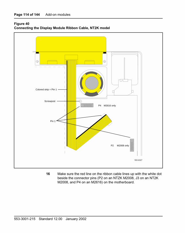
Page 114 of 144 Add-on modules
16 Make sure the red line on the ribbon cable lines up with the white dotbeside the connector pins (P2 on an NTZK M2008, J3 on an NT2KM2008, and P4 on an M2616) on the motherboard.
Figure 40Connecting the Display Module Ribbon Cable, NT2K model
. . . . . . . .. . . . . . . .
553-6327
Colored strip = Pin 1
Screwpost
Pin 1
. . . . . . . .. . . . . . . .
P2 M2008 only
P4 M2616 only
553-3001-215 Standard 12.00 January 2002

Add-on modules Page 115 of 144
17 Slide the ribbon cable connector onto the connector pins (P2 on anNTZK M2008, J3 on an NT2K M2008, and P4 on an M2616) on themother board.
18 Ensure that the pins line up with the connector correctly and carefullywork the connector on until it is firmly seated.
Reattaching the Base
19 Make sure the ribbon cable is lying flat and not caught over or underany alignment posts or studs on the telephone base. (For the M2616,allow it to cover the screwpost and do not replace the screw onre-assembly.)
20 Replace the base.
21 Insert all screws (except the center screw on the M2616) and tightenthem.
Reattaching the Footstand
22 If the telephone has a Meridian Programmable Data Adapter (MPDA)or Meridian Communications Adapter (MCA), plug its cable into thejack on the telephone base.
23 Replace the footstand, positioning it firmly on the base.
24 Insert and tighten all screws.
Note: Place the label supplied with the display on the outside of thebottom cover of the telephone. This allows proper identification andtracking of the option level of the set.
Reconnecting the Telephone
25 Reconnect all cords.
26 Turn the telephone right-side-up and place it in a normal operatingposition.
CAUTION
This connection is polarity sensitive.
Telephone and Attendant Console Installation

Page 116 of 144 Add-on modules
27 Reconnect the handset.
Installing NT2K24WA or NT2K25YL displays on NT2K setsUse Procedure 1 to install the display on the M2008 set. Use Procedure 1 onpage 119 to install the display on the M2616 set.
Procedure 1Installing and removing the M2008 Display on NT2K sets
1 Remove the handset and place the telephone upside down on top of alevel, solid work surface covered with soft material or paper to preventdamage to movable keys and the telephone face.
2 Disconnect all cords from the telephone.
3 Remove the two screws from the footstand assembly and unsnap thefootstand assembly by pressing inward at the back of the footstandwhere it meets the base and pulling upward.
4 If the telephone is equipped with an MPDA or MCA, unplug the datacable from the base telephone jack. Remove the four screws securingthe base to the telephone. Remove the base and set it aside.
5 The power supply board (if equipped) is located on the left side of thetelephone. Remove the two small screws from the power supply board(near the top) and set aside. Grasp the board firmly on each side.Carefully work the board loose until it is released.
6 If the telephone is not equipped with a display, go to step 9. If thetelephone is equipped with a display, go to step 7.
CAUTION WITH ESDS DEVICESBefore handling internal telephone components,discharge static electricity from hands and tools bytouching any grounded metal surface or conductor.
553-3001-215 Standard 12.00 January 2002

Add-on modules Page 117 of 144
Removing the display board
7 The display board is located at the left center of the telephone.Disconnect the display ribbon cable from the display board. Removethe small screw from the board. Disconnect the P0738600 cable fromconnector J3 on the M2008. Remove the board and cable from the set.To replace, go to step 9.
Removing the display
8 Remove the two or three screws from the display module. Remove thedisplay from the telephone. To install the display option, go to step 11.
Installing the display board
9 Connect the P0738600 cable to the J1 connector of the display board.Place the board on the mounting post (see Figure 41 on page 118).
10 Insert the self-tapping Phillips-head screw supplied with the displayinto the mounting hole (near the top). Tighten it firmly with a #1 Phillipsscrewdriver.
11 Connect the loose end of the P0738600 cable to the J3 pins of thetelephone. Press down until the connector slides onto the J3 pins andis firmly seated.
Installing the display
12 Place the display facedown near the top of telephone and align the twomounting holes of the display with the two mounting holes of thetelephone.
13 Insert two self-tapping Phillips-head screws from the faceplate into themounting holes; tighten them firmly with a #1 Phillips screwdriver.
Note: Do not allow R5 on the power supply board to become bentduring this procedure.
14 If the MPDA or MCA option is installed, install the power supply board(see Procedure 1 on page 101).
Telephone and Attendant Console Installation

Page 118 of 144 Add-on modules
15 Fold the ribbon cable near the connector to align with the J2 pins onthe display board, ensuring that the notch on the ribbon cable is facingtoward the display board. Carefully work the ribbon cable connectoronto the J2 pins until it is firmly seated. Route the cable flat beside thepower supply board, gathering excess cable under the display. Becareful not to press the cable beneath the alignment posts or studs ofthe base. See Figure 41 on page 118.
Figure 41Connecting the cable to the display board
553-6325
553-3001-215 Standard 12.00 January 2002

Add-on modules Page 119 of 144
16 Replace the base. If the telephone is equipped with an MPDA or MCA,reconnect the data cable to the base telephone jack and replace thefootstand (ensuring that the MPDA or MCA cable does not get pinchedbetween the base and footstand). Make sure the footstand is firmlyseated to the base.
Note: Place the label supplied with the display on the outside of thebottom cover of the telephone. This allows proper identification andtracking of the option level of the set.
17 Tighten all the screws, reconnect all cords, and place the telephone inthe normal operating position.
18 Perform the self-test (Procedure 1) and acceptance test procedures.See LD 31 in the Software Input/Output Guide Administration(553-3001-311).
Procedure 1Installing and removing the M2616 Display on NT2K sets
1 Remove the handset and place the telephone upside down on top of alevel, solid work surface covered with soft material or paper to preventdamage to movable keys and the telephone face.
2 Disconnect all cords from the telephone.
3 Remove the two screws from the footstand assembly and unsnap thefootstand assembly by pressing inward at the back of the footstandwhere it meets the base and pulling upward.
4 If the telephone is equipped with an MPDA or MCA, unplug the datacable from the base telephone jack. Remove the five screws securingthe base to the telephone. Remove the base and set it aside.
5 If the telephone is not equipped with a display, go to step 9. If thetelephone is equipped with a display, go to step 6.
CAUTION WITH ESDS DEVICESBefore handling internal components of telephones,discharge static electricity from hands and tools bytouching any grounded metal surface or conductor.
Telephone and Attendant Console Installation

Page 120 of 144 Add-on modules
Removing the display board
6 The display board is located at the left center of the telephone.Disconnect the display ribbon cable from the display board. Removethe small mounting screw from the board. Grasp the board firmly oneach end and pull upward to remove it. To replace it, go to step 9.
Removing the display
7 The power supply board is located on the left side of the telephone.Remove the two small screws from the power supply board (near thetop) and set them aside. Grasp the board firmly on each side. Carefullywork the board loose until released.
8 Remove the two or three screws from the display Module. Remove thedisplay from the telephone. To install the display, go to step 11.
Installing the display board
9 Place the J1 connector of the display board over the P4 pins of thetelephone (see Figure 41 on page 118). Press down slowly until J1slides onto the P4 pins and is firmly seated.
10 Insert the self-tapping Phillips-head screw supplied with the displayinto the mounting hole (near the top). Tighten firmly with a #1 Phillipsscrewdriver.
Installing the display
11 Place the display face-down near the top of the telephone and align thetwo mounting holes of the display with the mounting holes in thetelephone.
12 Insert two self-tapping Phillips-head screws from the faceplate into themounting holes; tighten them firmly with a #1 Phillips screwdriver.
13 Install the power supply board (see Procedure 13 on page 95). Thisstep is not necessary on the M2616 unless there are other hardwareoptions.
553-3001-215 Standard 12.00 January 2002

Add-on modules Page 121 of 144
14 Fold the ribbon cable near the connector to align it with the J2 pins onthe display board, ensuring that the notch on the ribbon cable is facingtoward the display board. Carefully work the ribbon cable connectoronto the J2 pins until firmly seated. Route the cable flat beside thepower supply board, gathering excess cable under the display. Becareful not to press the cable beneath the alignment posts or studs ofthe base. See Figure 41 on page 118.
Note: Do not allow R5 on the power supply board to become bentduring this procedure.
15 Replace the base. If the telephone is equipped with an MPDA or MCA,reconnect the data cable to the base telephone jack and replace thefootstand (ensuring that the MPDA or MCA cable does not get pinchedbetween the base and the footstand). Make sure the footstand is firmlyseated in the base.
Note: Place the label supplied with the display on the outside of thebottom cover of the telephone. This allows proper identification andtracking of the option level of the set.
16 Tighten all screws, reconnect all cords, and place the telephone in thenormal operating position.
17 Perform the self-test (see) and acceptance test procedures. SeeLD 31 in the Software Input/Output Guide Administration(553-3001-311)
External Alerter BoardUse this procedure to add an External Alerter Board to the M2006, M2008,M2216ACD, or M2616 telephone. See Figure 42 on page 124 forinformation on hooking up the third-party External Alerter device.
Telephone and Attendant Console Installation

Page 122 of 144 Add-on modules
Procedure 2Installing and removing the External Alerter Board
1 Remove the handset and place the telephone upside down on a level,solid work surface covered with soft material or paper to preventdamage to movable keys and the telephone face.
2 Disconnect all cords from the telephone.
3 Remove the two screws from the footstand assembly and unsnap thefootstand assembly by pressing inward at the back of the footstandwhere it meets the base and pulling upward.
4 If the telephone is equipped with an MPDA or MCA, unplug the datacable from the base telephone jack.
5 Remove the four screws securing the base of the telephone to the topcover. Remove the base and set aside.
6 If the telephone is not equipped with an External Alerter Board, go tostep 8. If replacing an existing External Alerter Board, go to step 7.
Removing the External Alerter Board
7 The External Alerter Board is located at the right center of thetelephone. Remove the screws from the board. Grasp the board firmlyon each end and pull upward to remove.
Installing the External Alerter Board
8 Place the H1 connector of the External Alerter Board over the P3 pinsof the telephone (see Figure 31 on page 95 for M2006/M2008; seeFigure 32 on page 96 for M2616/M2216ACD). Align the mounting holeover the mounting post. Carefully work H1 onto the P3 pins until firmlyseated. Place the self-tapping Phillips-head screw supplied with theExternal Alerter Board into the mounting hole and tighten it with a #1Phillips screwdriver.
CAUTION WITH ESDS DEVICESBefore handling internal components of telephones,discharge static electricity from hands and tools bytouching any grounded metal surface or conductor.
553-3001-215 Standard 12.00 January 2002

Add-on modules Page 123 of 144
9 To signal the External Alerter when the telephone’s handset orspeaker is active, place the jumpers (AO288529) connecting the tworight-most pins on the alerter board.
To signal the External Alerter when the telephone is ringing or buzzing,place the jumpers connecting the two left-most pins on the ExternalAlerter Board.
10 If the telephone is not yet equipped with the power supply board, installit (see Procedure 13 for M2006/M2008; see Procedure 1 on page 101for M2616/M2016S/M2216ACD).
Note: Do not allow R5 on the power supply board to become bentduring this procedure.
11 Replace the base. If the telephone is equipped with an MPDA or MCA,reconnect the data cable to the base telephone jack and replace thefootstand (ensuring that the MPDA or MCA cable does not get pinchedbetween the base and the footstand). Make sure the footstand is firmlyseated in the base.
12 Tighten all screws, reconnect the line cord, and place the telephone inthe normal operating position.
Note: Place the label supplied with the External Alerter on the outsideof the bottom cover of the telephone. This allows proper identificationand tracking of the option level of the set.
13 For the connecting block configuration, see Figure 42.
14 Perform the self-test (see Procedure 1 on page 32) and acceptancetest procedures. See LD 31 in the Software Input/Output GuideAdministration (553-3001-311).
Telephone and Attendant Console Installation
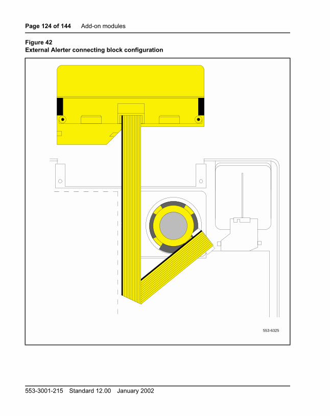
Page 124 of 144 Add-on modules
Figure 42External Alerter connecting block configuration
553-6325
553-3001-215 Standard 12.00 January 2002

Add-on modules Page 125 of 144
Key Expansion ModulesFollow the steps in Procedure 1 to add one (single) or two (double) KeyExpansion Modules to the M2616 or M2216ACD telephones.
Note 1: Have the associated footstand on hand before installing the KeyExpansion Modules.
Note 2: Adding a Key Expansion Module to a telephone requires apower supply board along with an additional power source (seeProcedure 2 on page 93 for the M2006/M2008; see Procedure 13 onpage 95 for the M2616/M2216ACD).
Procedure 1Installing and removing Key Expansion Module(s) on the M2616 andM2216ACD telephones
1 Remove the handset and place the telephone upside down on top of alevel, solid work surface covered with soft material or paper to preventdamage to movable keys and the telephone face.
2 Disconnect all cords from the telephone.
3 Remove the two screws from the footstand assembly and unsnap thefootstand assembly from the telephone by pressing inward at the backof the footstand where it meets the base and pulling upward.
Note: If the M2616/M2216ACD is equipped with a MeridianProgrammable Data Adapter (MPDA) or Meridian CommunicationsAdapter (MCA), it must be removed and installed into the KeyExpansion Module footstand. Use Procedure 1 on page 89.
4 If the telephone is not equipped with a Key Expansion Module(s), goto step 7. If replacing the Key Expansion Module(s), go to step 5.
Removing the Key Expansion Module(s)
5 Remove the screws from the footstand assembly (where it meets theKey Expansion Module), and unsnap the footstand assembly from theKey Expansion Module and telephone by pressing inward at the backof the footstand where it meets the base and pulling upward.
6 Remove the interface cable from the telephone by pressing down onthe locking tab. If equipped, remove the interface cable from the firstKey Expansion Module (closest to the telephone).
Telephone and Attendant Console Installation

Page 126 of 144 Add-on modules
Installing the Key Expansion Module(s)
7 If the telephone is not yet equipped with the power supply board, installthe Power Board (see Procedure 1 on page 97).
8 Align the bottom of the Key Expansion Module(s) to the bottom of thetelephone (see Figure 43 on page 127).
9 Snap the ribbon cable connector into the bottom interface jack on theKey Expansion Module.
Note: Use the cable supplied with the module. This is a special cablerequired for EMI compliance.
Snap the other end of the ribbon cable into the interface jack in thetelephone (left side). Gather the excess cable in the base of the KeyExpansion Module.
10 To add a second Key Expansion Module, snap a second ribbon cableconnector into the bottom interface jack on the second Key ExpansionModule. Snap the other end of the ribbon cable into the top interfacejack on the first Key Expansion Module (see Figure 43). Gather theexcess cable in the base of the second Key Expansion Module.
11 If the telephone is equipped with anMPDA or MCA, reconnect the datacable to the base telephone jack. Make sure the MPDA or MCA cable(and interface cable) do not get pinched between the base andfootstand.
12 Secure the footstand to the Key Expansion Module(s) and telephoneby placing the tabs of the footstand into the slots provided on the baseof the Key Expansion Module and telephone and pressing down. Makesure the footstand is firmly seated on the base.
Note: Use the cable supplied with the module. This is a special cablerequired for EMI compliance. Newer versions of the Key ExpansionModule use a longer modified cable than was used on earlier versions.
Ensure that the ribbon cable(s) are not pinched between the footstandand mounting posts.
553-3001-215 Standard 12.00 January 2002

Add-on modules Page 127 of 144
13 Insert the three (four if there are two modules) self-tapping,Phillips-head screws supplied with the Key Expansion Module into themounting holes in the bottom of the footstand. Tighten firmly with a #1Phillips screwdriver.
Note: Place the label supplied with the Key Expansion Module(s) onthe outside of the bottom cover or footstand of the telephone. Thisallows proper identification and tracking of the option level of the set.
14 Perform the self-test (see Procedure 1 on page 32) and acceptancetest procedures. See LD 31 in the Software Input/Output GuideAdministration (553-3001-311).
Figure 43Key Expansion Module connections (bottom view)
First Key Expansion Module
Second KeyExpansion Module
Set
553-1849
Telephone and Attendant Console Installation

Page 128 of 144 Add-on modules
Wall mountingThe M2006, M2008, M2616, and M2016S telephones are equipped with areversible footstand that allows for wall mounting. The wall mount clipshould be purchased and inserted in the handset well to hold the handsetsecurely in place on wall-mounted telephones. M2000 Series MeridianDigital Telephones can be hung on the wall with an installed display or KeyExpansion Module.
Note: The footstand cannot be reversed when the MeridianProgrammable Data Adapter or Meridian Communications Adapter isequipped, so telephones with data cannot bewall-mounted. Additionally,some wall plates are too deep to allow for wall mounting on top of theplate. In these cases, mount the telephone on the wall next to the plate.
An additional clip is provided for wall mounting the telephone. This clip isattached to the switchhook rest to prevent the handset from slipping whenmounted on the wall.
Procedure 1Wall mounting instructions for M2000 Series Meridian DigitalTelephones
1 Remove the handset and place the telephone upside down on top of alevel, solid work surface covered with soft material or paper to preventdamage to movable keys and the telephone face.
2 Disconnect all cords from the telephone.
3 Remove the two screws from the footstand assembly and unsnap thefootstand assembly by pressing inward at the back of footstand whereit meets the base, and pulling upward.
4 Rotate the footstand 180° and snap the footstand back into place onthe telephone bottom cover. Make sure the footstand is firmly seatedon the base of the telephone.
5 Tighten all screws and replace all cords.
6 Insert the wall mounting clip in the switchhook rest.
7 Mount the telephone on the wall using the wall mount holes providedon the bottom of the footstand.
553-3001-215 Standard 12.00 January 2002

Add-on modules Page 129 of 144
TroubleshootingUse Table 21 to check problems encountered when installing M2000 SeriesMeridian Digital Telephones and their options.
Table 21Troubleshooting M2000 Series Meridian Digital Telephones (Part 1 of 4)
Symptom Solution
Telephone does not work. 1 Unplug the line cord from the telephone and plug itback in.
2 If the telephone uses external power, make sure thetransformer or closet power supply is properlyconnected and that the power supply board isproperly installed.
If the telephone does not use external power, makesure that jumpers are placed connecting the bottomtwo sets of pins on the P1 connector on the maincircuit board.
All LCDs flash and telephonedoes not function.
1 Press the Release (Rls) key.
2 Unplug the line cord from the telephone and plug itback in.
Telephone wobbles. 1 Ensure that all cords are properly routed throughchannels in the footstand.
2 Check that the footstand is firmly seated on thetelephone.
3 Ensure that all feet are firmly seated in the footstand.
Display does not work. 1 Unplug the line cord from the telephone and plug it inagain.
2 Ensure that the transformer is plugged in or the closetpower is connected (M2008 only).
3 Ensure that the power supply board is installedproperly (M2008 only).
Telephone and Attendant Console Installation

Page 130 of 144 Add-on modules
Display does not work. (cont.) 4 Check that the display ribbon cable is properlyconnected to the display board and has not beenpinched.
5 Ensure that the display board is installed correctlyand held securely with a mounting screw.
6 M2006, M2008, M2616 – ensure that ADD class ofservice is configured in LD 11. See the SoftwareInput/Output Guide Administration (553-3001-311).
There is no response when youtype <CR> or AT at the terminal.
1 Press the P key and dial 28 to make sure you are interminal mode.
2 Make sure the PC or terminal’s has power and isonline.
3 If the equipment connected to the MCA is notconfigured as Data Terminal Equipment, it isnecessary to connect using a null modem cable.
4 Make sure the MCA is receiving external power.Check to see that the power cables are connectedproperly and the external power supply is running.
5 If there is a display on the telephone, press the P keyand dial 63 to get into EIA Monitor mode. Be sure theMCA is receiving signals from the terminal bywatching the display while entering carriage returnson the keyboard. If the indicator flashes, theconnection is correct. If not, check the cable to makesure it is the standard RS-232 and is properlyconnected.
6 Press the P key and dial 62 to ensure that the MCA isin the asynchronous mode. Press the P key and dial20 to change to the asynchronous mode.
7 Press the P key and dial * to ensure that the MCA isin the idle mode.
Table 21Troubleshooting M2000 Series Meridian Digital Telephones (Part 2 of 4)
Symptom Solution
553-3001-215 Standard 12.00 January 2002

Add-on modules Page 131 of 144
The prompt CALLCONNECTED. SESSIONSTARTS is followed byRELEASE.
Check the configuration parameters of the far end datadevice. If they do not match those of the MCA, the call willbe dropped. Change the parameters of your MCA to match.
Garbled prompts are sent toyour terminal when you type<CR>.
Enter a period ( . ) followed by <CR> to perform anautoparity.
You are connected to a hostcomputer, but get no responsewhen you try to log on.
First, release the call. Turn on Remote Loopback and makethe call again. Type some characters at the terminal. If thecharacters echo back and appear on the terminal, theproblem is with the far end data device. If the characters donot appear on the terminal, the problem is with the MCA.Contact the telephone system administrator.
You try to make a data call fromthe initial prompt (or Main menu)in keyboard dialing. You see theprompt CALLING.
First, hold down the break key(s) for two seconds, enter<CR>, and try again to make the data call. If the problempersists, the MCA is probably disabled. Contact thetelephone system administrator.
MCA does not operate at all. 1 Check the LED in the back of the telephone to see if itis flashing. If the LED is steadily lit, the MCA needs tobe configured in the system, or it may be bad. If theLED is not lit, the MCA requires external power.
2 Make sure the cable from the terminal or PC isconnected to the MCA.
3 Check the data parameters for the display.
4 Be sure the transformer is plugged in, or the closetpower is connected.
5 Be sure the cable between the MCA and thetelephone is connected and has not been pinched.
6 Be sure the power card is installed correctly. Verifythat the jumper settings are correct for either RS-232or V.35 (whichever you are using).
Table 21Troubleshooting M2000 Series Meridian Digital Telephones (Part 3 of 4)
Symptom Solution
Telephone and Attendant Console Installation

Page 132 of 144 Add-on modules
Key Expansion Module does notwork.
1 Unplug and plug in the line cord.
2 Ensure that the transformer is plugged in or that thecloset power supply is connected.
3 Ensure that the power supply board is installedproperly.
4 Make sure that the ribbon cable connecting thetelephone and the Key Expansion Module is routedproperly and is not pinched.
External Alerter does not work. 1 Ensure that the External Alerter Board is installedproperly.
2 Check that connections between the alerting deviceand the telephone connecting block are correct.
3 Make sure that the jumpers are placed on the pins onthe External Alerter Board as described inProcedure 2 on page 122.
4 Ensure that the transformer is plugged in or the closetpower is connected.
5 Ensure that the power supply board is installedproperly.
Note 1: If the pseudorandom pattern 511 data is idle, the telephone keypad dialing is inoperative. Use therelease key to clear this condition.
Note 2: If using an RS-232 cable to connect the MCA to an ADM3/5 terminal, be sure that pin 22 isdisconnected.
Note 3: Change the baud rate before changing the mode from synchronous to asynchronous.
Note 4: Some terminals may drop DTR with the break. If this happens, RELEASE is not displayed.
Table 21Troubleshooting M2000 Series Meridian Digital Telephones (Part 4 of 4)
Symptom Solution
553-3001-215 Standard 12.00 January 2002

Add-on modules Page 133 of 144
Figure 44Flowchart for troubleshooting MCA
Power up
LED checkLED lit Attach
RS-232 cable to DTE
LED litMCA bad
Distinctive flash
Telephone bad(A44-A64 interface check)
<cr> No menuAT
<cr>No AT echo
P66KBD<cr>
Enter number or H for help
No menu
P28 (Note)<cr>
MCAbad
Call connectedType few charactersEchoes characters
No echo MCA bad
MCA good
Note: If equipped with display, check with P62 whether it is Terminal mode or Host mode.
553-5526
Set to remote loopback modeM <cr>R <cr>
Remote loopback: Y <cr>Q <cr>
or program P38 (when equipped with display)
<cr>, dial data DN
Telephone and Attendant Console Installation

Page 134 of 144 Add-on modules
553-3001-215 Standard 12.00 January 2002


Family Product Manual Contacts Copyright FCC notice TrademarksDocument number Product release Document release Date Publish
Meridian 1
Telephone and AttendantConsole Installation
Copyright © 1989 –2002 Nortel NetworksAll Rights ReservedInformation is subject to change without notice. NortelNetworks reserves the right to make changes indesign or components as progress in engineering andmanufacturing may warrant. This equipment has beentested and found to comply with the limits for a Class Adigital device pursuant to Part 15 of the FCC rules,and the radio interference regulations of IndustryCanada. These limits are designed to providereasonable protection against harmful interferencewhen the equipment is operated in a commercialenvironment. This equipment generates, uses and canradiate radio frequency energy, and if not installed andused in accordance with the instruction manual, maycause harmful interference to radio communications.Operation of this equipment in a residential area islikely to cause harmful interference in which case theuser will be required to correct the interference at theirown expense.SL-1 and Meridian 1 are trademarks of NortelNetworks.Publication number: 553-3001-215Document release: Standard 12.00Date: January 2002Printed in Canada