international magazine of endodontology
DESCRIPTION
Revista RottsTRANSCRIPT

rootsinternational magazine ofendodontology
| specialLaser in endodontics
| case reportRevascularisation of the necrotic open apex
| clinical techniqueThe WaveOne single-file reciprocating system
12011
i s sn 1616-6345 Vol. 7 • Issue 1/2011

Journey into a new dental experience with speed, precision and great results. Visit Fotona at IDS 2011, Hall 10.2, Booth M050.www.lightwalkerlaser.com
ww
w.fo
tona
.com
Unmatched simplicity of use: Pre-sets for over 40 applications Intuitive user navigation Balanced and weightless OPTOflex arm Automatic Nd:YAG handpiece detection system Er:YAG scanner ready
Supreme clinical results in: TwinLightTM Perio Treatments (TPT) TwinLightTM Endo Treatments (TET) No sutures soft tissue surgery Gentle TouchWhiteTM bleaching Patient-friendly conservative dentistry
The universe at your fingertips.
After endo laser treatment there is no smear layer around the opening of the lateral canal.
Introducing the highest technology dental laser system88
897/
4.0

I 03
editorial _ roots I
roots1_2011
Dr Yoshio Yahata
_The objectives of root-canal preparation are to remove all pulp tissue, bacteria andtheir by-products and to produce sufficient canal space for disinfection and 3-D obturation.Many techniques have been introduced for proper preparation, one of which is the balancedforce technique. This technique uses hand files with alternating clockwise and counter-clockwise motion in an attempt to minimise canal transportation and decrease the amountof stress placed on a file during use.
Recently, on the basis of the principles of the balanced force technique, a new canalpreparation technique using rotary NiTi files with reciprocal motion has been advocated.Previous studies have demonstrated that by using asymmetric reciprocal motion, the tech-nique is capable of canal-centring when preparing root canals, especially in curved canals.Furthermore, working time, over-instrumentation, apical extrusion of debris and incidenceof file fracture can be significantly lower using NiTi files with reciprocal motion than withconventional continuous rotation.
As has been indicated by numerous studies, fracture of NiTi files is still a major concern.File fracture occurs in two ways: fatigue or torsional failure. Fatigue failure is the result of repeated compression and tension on files, especially in curved canals, while torsionalfailure occurs when a file tip binds and the remainder continues to rotate. In a clinical setting, these two failures have an influence on one another.
The incidence of NiTi file fracture is reported to be lower with reciprocal motion than continuous rotation. With the newly proposed technique, the file would frequently engagedentine at its tip, but counter-clockwise rotation would immediately disengage the file, resulting in the reduction of deformation and torsional fracture.
As clinicians, we should consider and weigh the advantages and disadvantages of anynew technique. Furthermore, it is imperative that we constantly seek better treatmentstrategies to reduce the risk for the patient. The proposed new system using a single fileclaims to be a promising method, but few studies have demonstrated the effectiveness ofthis technique. Therefore, further studies and discussion on this system are necessary.
Yours faithfully,
Dr Yoshio YahataGraduate School of Medical and Dental SciencesTokyo Medical and Dental UniversityTokyo, Japan
Dear Reader,
ӗ
I editorial
03 Dear Reader| Dr Yoshio Yahata, Guest Editor
I special
06 Laser in endodontics (Part I)| Prof Giovanni Olivi et al.
I research
10 Root-canal anatomy of the permanent mandibularfirst molar—Clinical implications and recommendations| Dr Carlos Heilborn et al.
I case report
14 Revascularisation of the necrotic open apex| Dr Antonis Chaniotis
18 When nature laughs at endodontists: Two case reports| Dr Bojidar Kafelov
20 Diagnosis of vertical root fractures using CBCTand an alternative treatment modality| Dr Senem Yigit Özer
24 Bypassing a fractured instrument| Dr Rafaël Michiels
I clinical technique
28 The WaveOne single-file reciprocating system| Dr Julian Webber et al.
34 R-phase advantages in shaping curves| Dr Philippe Sleiman
I feature
38 An interview with Dr Martin Rickert,Executive Chairman Sanavis Group
I industry report
40 Filling root-canal systems—The Calamus 3D Obturation Technique| Dr Clifford J. Ruddle
I industry news
46 The EndoWave hybrid concept:Effective and reliable root-canal preparation| J. Morita
I meetings
48 International Events
I about the publisher
49 | submission guidelines
50 | imprint
I content _ roots
page 28 page 34 page 40
page 6 page 18 page 24
04 I roots1_2011
Cover image courtesy of Prof Marco Versiani
and Prof Manoel D. Sousa Neto, Ribeirão Preto
Dental School, University of São Paulo.

Simplicity is the real innovation
• Only one NiTi instrument per root canal in most cases
• Decreases the global shaping time by up to 40%
• Reciprocating technology respecting the root canal anatomy
• Single use as new standard of care
www.dentsplymai l lefer.com
Projet5_Mise en page 1 08.02.11 16:00 Page1

06 I
I special _ laser
_The main goals of endodontic treatment are the effective cleaning of the root-canal system. Tradi-tional endodontic techniques use mechanical instru-ments, as well as ultrasound and chemical irrigation toshape, clean and completely decontaminate the endo -dontic system.
The complexity of the root-canal system is wellknown. Numerous lateral canals, of various dimen-sions and with multiple morphologies, branch off fromthe principal canals. A recent study found complexanatomical structures in 75% of the teeth analysed.The study also found residual infected pulp after thecompletion of chemo-mechanical preparation, bothin the lateral canals and in the apical structures of vital and necrotic teeth associated with peri-radicularinflammation.1
The effectiveness of the debridement, cleaningand decontamination of the intra-radicular space is limited, given the anatomical complexity and theinability of common irrigants to penetrate into thelateral canals and the apical ramifications. Therefore,it appears advisable to search for new materials, tech-niques and technologies that can improve the clean-ing and decontamination of these anatomical areas.
The use of lasers in endodontics has been studiedsince the early 1970s, and lasers have been morewidely used since the 1990s.2–7 In this regard, Part I of this article will describe the evolution of laser techniques and technologies. The second part, whichwill be published in roots 2/2011, will present thestate-of-the-art effectiveness of these instrumentsin the cleaning and decontamination of the endo -dontic system and take a look at the future, present-ing recent preliminary studies on new methods ofutilising laser energy.
_Lasers in endodontics
Laser technology was introduced to endodonticswith the goal of improving the results obtained with traditional procedures through the use of lightenergy by increasing cleaning ability and the removalof debris and the smear layer from the root canals andalso improving the decontamination of the endo -dontic system.
Different wavelengths have been shown to be effective in significantly reducing bacteria in infectedcanals and studies have confirmed these results in vitro.8 Further studies have demonstrated the
Fig. 1_Lasers and the electro -
magnetic spectrum of light.
roots1_2011
Laser in endodontics(Part I)Authors_ Prof Giovanni Olivi, Prof Rolando Crippa, Prof Giuseppe Iaria, Prof Vasilios Kaitsas, Dr Enrico DiVito & Prof Stefano
Benedicenti, Italy & USA
Fig. 1

I 07
special _ laser I
roots1_2011
efficiency of lasers in combination with commonlyused irrigants, such as 17% EDTA, 10 % citric acid and 5.25% sodium hypochlorite.9 The action of thechelating substances facilitates the penetration oflaser light, which can penetrate into the dentinal wallsup to 1mm in depth and have a stronger decontami-nating effect than chemical agents.8,9 Other studieshave investigated the ability of certain wavelengthsto activate the irrigating solutions within the canal.This technique, which is termed laser-activated
irrigation, has been shown to be statistically more effective in removing debris and the smear layer inroot canals compared with traditional techniques andultrasound.10–12 A recent study by DiVito et al. demon-strated that the use of the Erbium laser at subablativeenergy density using a radial and stripped tip in combination with EDTA irrigation results in effectivedebris and smear layer removal without any thermaldamage to the organic dentinal structure.13
_Electromagnetic spectrum of light andlaser classification
Lasers are classified according to their location on the electromagnetic spectrum of light. They can be visible and invisible, near, medium and far infraredlaser. Owing to optical physics, the function of thevarious lasers in clinical use differs (Fig. 1). In the visible spectrum of light, the green light laser (KTP, a neodymium duplicate of 532nm) was introduced indentistry in recent years. There have been few studiesconcerning this wavelength. Its delivery through aflexible optical fibre of 200 µ allows its use in endo -dontics for canal decontamination and has shownpositive results.14,15
Near infrared lasers (from 803nm to 1,340nm)were the first to be used for root decontamination. Inparticular, the Nd:YAG (1,064nm), introduced at thebeginning of the 1990s, delivers laser energy throughan optical fibre.5 The medium infrared lasers, the Erbium (2,780nm and 2,940nm) laser family, also produced at the beginning of the 1990s, have beenequipped with flexible, fine tips only since the begin-ning of this century and have been used and studiedin endodontic applications. The far infrared laser CO2
(10,600nm) was the first to be used in endodontics for decontamination and apical dentine melting inretrograde surgery. It is no longer used in this fieldwith the exception of vital pulp therapy (pulpotomyand pulp coagulation). The lasers considered here forendodontic applications are the near infrared laser—diode (810, 940, 980 and 1,064nm) and Nd:YAG(1,064nm)—and the medium infrared lasers—Erbium,Chromium: YSGG (Er,Cr:YSGG; 2,780nm) and Erbium:YAG (2,940nm). A brief introduction to the basicphysics of laser–tissue interaction is essential for understanding the use of lasers in endodontics.
_Scientific basis for the use of lasers inendodontics
Laser–tissue interaction
The interaction of light on a target follows the rulesof optical physics. Light can be reflected, absorbed,diffused or transmitted.
_Reflection is the phenomenon of a beam of laserlight hitting a target and being reflected for lack ofaffinity. It is therefore obligatory to wear protectiveeyewear to avoid accidental damage to the eyes.
_Absorption is the phenomenon of the energy inci-dent on tissue with affinity being absorbed andthereby exerting its biological effects.
_Diffusion is the phenomenon of the incident lightpenetrating to a depth in a non-uniform mannerwith respect to the point of interaction, creating biological effects at a distance from the surface.
_Transmission is the phenomenon of the laser beambeing able to pass through tissue without affinityand having no effect.
The interaction of laser light and tissue occurswhen there is optical affinity between them. This interaction is specific and selective based on absorp-tion and diffusion. The less affinity, the more light will be reflected or transmitted (Fig. 2).
Effects of laser light on tissue
The interaction of the laser beam on target tissue, via absorption or diffusion, creates biologicaleffects responsible for therapeutic aspects that canbe summarised as:
_photo-thermal effects;_photomechanical effects (this includes photo -
acoustic effects); and_photochemical effects. Fig. 2_Laser–tissue interaction.
Fig. 2

08 I
I special _ laser
The diode laser (from 810nm to 1,064nm) and the Nd:YAG (1,064nm) belong to the near infrared region of the electromagnetic spectrum of light. They interact primarily with soft tissue by diffusion(scattering). The Nd:YAG laser has a greater depth ofpenetration in soft tissues (up to 5mm), while thediode laser is more superficial (up to 3mm). Theirbeam is selectively absorbed by haemoglobin, oxy-haemoglobin and melanin, and has photo-thermaleffects on tissue. Therefore, their use in dentistry islimited to the vaporisation and incision of soft tissue.They are also used for dental whitening with a laserbeam, by thermal activation of the reagent. In endo-dontics, they currently represent the best system fordecontamination, owing to their ability to penetratethe dentinal walls (up to 750µ with the 810nm diodelaser; up to 1mm with the Nd:YAG)8 and for the affin-ity of these wavelengths with bacteria, destroyingthem through photo-thermal effects.16
The Erbium lasers (2,780nm and 2,940nm) belongto the medium infrared region and their beam is pri-
marily absorbed superficially by soft tissue between100 and 300µand up to 400µby the dentinal walls.8,17
The chromophore target is water, which is whytheir use in dentistry extends from soft to hard tissue.Owing to the water content of the mucosa, gingiva,dentine and carious tissue, Erbium lasers vaporise andaffect these tissues thermally. The explosion of thewater molecules generates a photomechanical effectthat contributes to the ablative and cleaning process(Fig. 3).18–20
Parameters that influence the emission of laser
energy
Laser energy is emitted in different ways with various instruments. In diode lasers, the energy isemitted in a continuous wave (CW mode). A mechan-ical interruption of the energy emission is possible(properly called ‘gated’ or ‘chopped’ and improperlycalled ‘pulsed’), allowing for better control of thermalemission. The pulse duration and intervals are in milliseconds or microseconds (time on/off).
The Nd:YAG laser and the Erbium family emit laserenergy in a pulsed mode (also called free-runningpulse), so that each pulse (or impulse) has a beginningtime, increase and an end time, referred to as a Gaussian progression. Between pulses, the tissue hastime to cool (thermal relaxation time), allowing forbetter control of thermal effects (Fig. 4).
The Erbium lasers also work with an integrated water spray, which has the double function of bothcleaning and cooling. In the pulse mode, a string of
Fig. 3_Coefficients of tissue
absorption.
roots1_2011
Table I_Laser light emission
parameters.
P power (in W)
E energy (in J)
R pulse repetition rate (in Hz)
Pd power density or density of power (in W/cm2)
F fluence or density of energy (in J/cm2)
P(W) average power = E x R
PP(W) peak power = E; length of single pulse (in seconds)Table I
Fig. 3

I 09
special _ laser I
roots1_2011
pulses is emitted with a different pulse repetition rate(improperly called ‘frequency’) referred to as the Hertzrate (generally from 2 to 50 pulses) per second. Thehigher emission repetition rate acts in a similar way tothe CW mode, while the lower repetition rate allowsfor a longer time for thermal relaxation. The emissionfrequency (pulse repetition rate) influences the aver-age power emitted, according to the formula shownin Table I.
Another important parameter to consider is the‘shape’ of the pulse, which describes the efficiencyand the dispersion of the ablative energy in the form of thermal energy. The length of the pulse, frommicroseconds to milliseconds, is responsible for theprincipal thermal effects. Shorter pulses, from a fewmicroseconds (<100) to nanoseconds, are responsiblefor photomechanical effects. The length of the pulseaffects the peak power of each single pulse, accord-ing to the formula in Table I. Dental lasers available onthe market today are free-running pulsed lasers, theNd:YAG with pulses of 100 to 200µs and the Erbiumlasers with pulses of 50 to 1,000µs. Furthermore,diode lasers emit energy in CW that can be mechani-cally interrupted to allow the emission of energy with pulse duration of milliseconds or microsecondsdepending on the laser model.
Effects of laser light on bacteria and dentinal walls
In endodontics, lasers use the photo-thermal and photomechanical effects resulting from the interaction of different wavelengths and differentparameters on the target tissues. These are dentine,the smear layer, debris, residual pulp and bacteria inall their various aggregate forms.
Using different outputs, all the wavelengths destroy the cell wall due to their photo-thermal effect. Because of the structural characteristics of thedifferent cell walls, gram-negative bacteria are moreeasily destroyed with less energy and radiation thangram-positive bacteria.16 The near infrared lasers are not absorbed by hard dentinal tissues and have no ablative effect on dentinal surfaces. The thermaleffect of the radiation penetrates up to 1mm into the dentinal walls, allowing for a decontaminating effect on deeper dentine layers.8 The medium infraredlasers are well absorbed by the water content of thedentinal walls and consequently have a superficialablative and decontaminating effect on the root-canal surface.8,16
The thermal effect of the lasers, utilised for its bac-tericidal effect, must be controlled to avoid damageto the dentinal walls. Laser irradiation at the correctparameters vaporises the smear layer and the organicdentinal structure (collagen fibres) with characteris-
tics of superficial fusion. Only the Erbium lasers havea superficial ablative effect on the dentine, which appears more prevalent in the intertubular areasricher in water than in the more calcified peri-tubularareas. When incorrect parameters or modes of use areemployed, thermal damage is evident with extensiveareas of melting, recrystallisation of the mineral matrix (bubble), and superficial microfractures con-comitant with internal and external radicular carbon-isation.
With a very short pulse length (less than 150µs),the Erbium laser reaches peak power using very low energy (less than 50mJ). The use of minimally ablative energy minimises the undesirable ablativeand thermal effects on dentinal walls while the peakpower offers the advantage of the phenomena of water molecule excitation (target chromophore) andthe successive creation of the photomechanical andphotoacoustic effects (shock waves) of the irrigantsolutions introduced in the root canal on the dentinalwalls. These effects are extremely efficient in cleaningthe smear layer from the dentinal walls, in removingthe bacterial biofilm and in the canal decontamina-tion, and will be discussed in Part II.10–13_
Editorial note: A complete list of references is available
from the publisher.
Fig. 4_Methods of laser light
emission.
Prof Giovanni Olivi
University of Genoa DI.S.TI.B.MO
Department of Restorative Dentistry Genoa, Italy
Private Practice Piazza F. Cucchi, 3
00152 Rome
Italy
_contact roots
continuous wave mode
gated mode
pulsed modeFig. 4

10 I
I research _ mandibular first molars
_The world of endodontics has incorporated new technologies, instruments and materials in thepast decade, such as operating microscopes, digitalradiography, CBCT, NiTi rotary shaping files, sonic andultrasonic instruments, and new irrigation deliverysystems. However, despite all these improvements,the overall outcome, especially of non-surgical endo -dontics, has not increased significantly.1–8
Why? If we consider this critically, we can deter-mine that there are two important factors directly related to prognosis that have limited our advance-ment: predictable eradication of microorganisms andaccess to the full anatomy of the canal system inwhich they might be harboured.
The mandibular first molar (MFM) is the more frequently endodontically treated tooth.9–11 In a
study by Swartz et al., the success rate of endodonti-cally treated teeth was 87.79%, with a significantlylower success rate of 81.48% for MFMs.12 It is well accepted that a unique cleaning and shaping tech-nique is not suitable for all cases. Therefore, the endodontist should be able to fully understand thetooth morphology and root-canal configurations inorder to select the most appropriate treatmentmodality for a particular case,13 thereby increasingthe healing rate.14–16
Based on the above information, our group re-cently published a systematic review on root anatomyand canal configuration of the permanent MFM withreference to 41 studies and a total of 18,781 teeth.17 Asummary of the data obtained is presented in Table I.This review provided significant information directlyrelated to our clinical procedures.
Figs. 1a & b_Root-canal treatment
on a three-rooted MFM:
pre-op radiograph (Fig. 1a);
post-op radiograph (Fig. 1b).
roots1_2011
Root-canal anatomy of thepermanent mandibular firstmolar—Clinical implicationsand recommendationsAuthors_ Dr Carlos Heilborn, Paraguay; Dr Óliver Valencia de Pablo & Dr Roberto Estevez, Spain & Dr Nestor Cohenca, USA
Fig. 1a Fig. 1b

I 11
research _ mandibular first molars I
roots1_2011
_Number of roots
A literature review revealed a strong correlationbetween the presence of a third root in 13% of teethand the ethnicity of the patients, particularly Asians,Mongolians and Eskimos.18
In order to determine the presence of additionalroots visually, several radiographic exposures are required. Initial off-angle radiographs are essentialduring MFM treatment (Fig. 1a).19, 20 Initially, a file located in the extra root, may give the appearance ofa perforation.21 If radiographic findings are not defin-
itive, information provided by electronic foramen locators provides reliable readings to make a differ-ential diagnosis and confirm the presence of the additional canal. Walker and Quackenbush concludethat simple analysis of bitewings allows for the detection of disto-lingual (DL) roots in 90% of cases.18
In 1990, Carlsen and Alexander reported on a studyof 398 permanent mandibular molars with a linguallylocated supernumerary root.22 This macrostructure,the radix entomolaris, presents high variation in regards to shape and curvature. When the position ofthis third root is buccal, it is called the radix paramo-
Table I_Results of mandibular first
lower molar systematic review
(Valencia de Pablo et al., 2010).
Figs. 2a–f_Root-canal treatment on
an MFM: pre-op radiograph (Fig. 2a);
working length radiograph (Fig. 2b);
post-op radiograph demonstrating a
fine projection of sealer between
MB and ML (Fig. 2c); working length
radiograph of middle mesial canal
(Fig. 2d); post-op, ortho-radial
radiograph (Fig. 2e); post-op,
off-angle radiograph demonstrating
three canals treated on mesial root
(Fig. 2f).
Number of rootsNumber of molars studied 18,781 3-rooted molars in % 13 % (2,450)
Total number of canalsNumber of molars studied 4,745 61.3 % 3 canals 35.7 % 4 canals 0.8 % 5 canals
Number of canals in mesial rootNumber of mesial roots studied 4,535 3.3 % 1 canal 94.2 % 2 canals 2.6 % 3 canals
Mesial and distal roots. Canal system configurationType I (1-1) Type II (2-1) Type IV (2-2) Type VIII (3-3)
Number of mesial roots studied 4,331 35 % 52.3 % 0.9 %Number of distal roots studied 2,992 62.7 % 14.5 % 12.4 %
Number of foramina in mesial and distal roots1 foramen 2 foramina 3 foramina
Number of mesial roots studied 4,817 38.2 % 59.2 % 1.6 %Number of distal roots studied 3,378 77.2 % 22.2 %
Intercanal communications. Type V isthmusesMesial root Distal root
Number of molars studied 1,615 54.8 % middle & apical 1/3 20.2 % middle 1/3Table I
Fig. 2a Fig. 2b Fig. 2c
Fig. 2d Fig. 2e Fig. 2f

12 I
I research _ mandibular first molars
laris. Its shape and curvature are highly variable (Fig. 1b).23–25 Typically, the axis of the root faces thebuccal aspect of the molar. Therefore, it could be easier to select the disto-buccal cusp as a referencepoint, instead of the typical DL. The combination ofthe slope present at the orifice and the buccal curva-ture at the apical third results in a highly complexcanal to be instrumented and irrigated. To preventmishaps, it is advisable to choose a small and highlyflexible instrument when treating the apical portion.
Diagnosis, access and proper treatment of thethird root within the complex canal system are essen-tial in order to achieve successful endodontic treat-ment. In cases of endodontic surgical procedures, thethird root will be a significant challenge.19 In a recentpublication, Tu et al. report high DL root prevalenceamongst the Taiwanese population.26 The authorsfound that the inability to recognise and treat this extra root was directly correlated to treatment failure,leading to tooth extraction.
Table I summarises the findings of a systematic review compiling data on 4,745 MFMs.17 On average,three canals were present in 61.3% of cases, followedby four canals in 35.7% of cases and five canals in almost 1% of cases. In vivo studies performed by endodontists demonstrated the presence of fourcanals in 45% of the treated cases.27–30 Five canalswere found in 0.8% of the samples, while case reportshave demonstrated the possibility of six- and evenseven-root canals.31,32
_Mesial root morphology
A systematic literature review of studies concern-ing more than 4,000 mesial roots confirmed the presence of two root canals in 94.2%.17 These canalsmerge in a common apical foramen (type II) in 35% of cases or remain independent with separate apicalforamina in 52.3% of cases (type IV of Vertucci’s classification; Table I). A clinical approach to identify-ing the internal canal configuration should includeevaluation of the distance between the main orifices.The short distance between mesiobuccal (MB) andmesiolingual (ML) orifices often leads to confluenceand termination in a common foramen. An increaseddistance is directly correlated to type IV configurationwith two separate foramina.33
When facing a type IV configuration (2-2), the clinician should treat the canals independently. Formerging canals, Castellucci explains that initially thecanals should not be instrumented to working length,thus preventing unnecessary removal of dentine.34
In addition, full instrumentation of both canals toworking length will create an hour-glass preparation,with the narrowed area at the junction and wideningcanal space apical to the junction. The 3-D obturationin this case is much more complicated and poses a riskof extrusion, as well as leaving some empty space inthe most apical divergent zone.29 It is clinically saferand easier to instrument the ML canal to workinglength and the MB to the level of the confluence, since the latter is the closest to the outer surface ofthe root and also presents more severe curvaturesthan the ML.35,36
Marroquin et al. report that the average size of the maximum diameter is 0.31mm when the apicalforamen is common.37 In contrast, the average maxi-mum diameter does not exceed 0.25mm when twoseparate foramina are present. This data suggeststhat treating a type IV configuration could allow amore conservative apical preparation. Nevertheless,canal preparation must always be correlated to theanatomy and the microbiological status of the canal.While vital cases should be treated more conser -vatively, infected canals may require larger apicalpreparations to allow efficient irrigation and disin-fection.38,39
Several publications report the presence of threecanals in the mesial root.40,41 Our systematic reviewreports an incidence of 2.6% (Figs. 2 & 3).17 In order tolocalise it, access modifications are required. Briefly,once the main canals have been localised and their access instrumented, small burs or ultrasonic tips areused to remove the dentinal bridge that connectsboth entries, providing a direct view of the angleformed by the mesial wall and the floor of the pulp
Figs. 3a–f_Root-canal treatment on
an MFM: pre-op radiograph (Fig. 3a);
working length radiograph (Fig. 3b);
working length off-angle radiograph
after location of three canals on
mesial root (Fig. 3c);
post-op, off-angle radiograph
demonstrating three canals treated
on mesial root (Fig. 3d);
post-op, ortho-radial
radiograph (Fig. 3e);
final restoration control (Fig. 3f).
roots1_2011
Fig. 3a Fig. 3b Fig. 3c
Fig. 3d Fig. 3e Fig. 3f

I 13
research _ mandibular first molars I
roots1_2011
chamber, exposing the developmental groove be-tween the two main canals. An endodontic explorer isthen used, followed by negotiation with small files.Additionally, the use of operating microscopes fur-ther improves the possibility of finding and treatingthis accessory canal.42 Taking into consideration thedistal concavity of the mesial root, instrumentation ofthe third medial canal must be done carefully usingsmall instruments to avoid stripping perforations.27
The middle mesial is an entirely independent canal inup to 25% of cases.17
_Distal root morphology
Gulabivala et al. evaluated 139 MFMs and foundthat 74.8% of the distal roots had a flattened MD morphology.21 They also noted that conical distal rootsfrequently presented a single canal, while the vast majority had more complex configurations. Therefore,routine access openings should be modified in searchof a second or a ribbon-shaped canal. The access design has evolved from the classic triangular to a rectangular shape shifted to the MB.27,43
Martinez-Berna and Badanelli were the first to report a third canal in the distal root and termed it thedisto-central (DC) root canal.44 A literature review setsthe incidence of DC at 1%.21,31,39,45–50
_Intercanal communications
The morphology and buccolingual width of themesial root allow for intercanal communications and isthmuses (Fig. 4). An isthmus (anastomosis) is defined as a pulpal passageway that connects two ormore canals in the same root.51 In young patients, we should expect to find large canals with wide isthmuses. As secondary dentine is depositedthroughout the maturation of the tooth, these largecommunications are divided into smaller ones and,eventually, its frequency decreases after age 40.52
Of the 1,615 MFMs reviewed, 50% of the mesialand 20% of the distal roots presented isthmuses oftype V. Type V is recognised as a true connection orwide corridor of tissue between the two main canals.53
Therefore, the presence of isthmuses should be considered the rule rather than the exception whentreating young MFMs.
Given the extreme difficulty in disinfecting theseinaccessible spaces,54 our efforts should be focusedon improving our irrigation protocols with the moreefficient systems available today. The clinical impor-tance of recognising, treating and disinfecting isth-muses was recently pointed out by Von Arx, who iden-tified complete cross-anastomosis in 29% of cases offailed root-canal therapies requiring apical surgery.55
_Conclusion
The following is a summary of the findings of ourreview:
1. The number of roots in the MFM is directly relatedto the ethnicity of the population studied.
2. The instrumentation of the third root requires a different access and the use of small and flexible instruments, considering the curvature at the apical third.
3. Mesial roots present two canals on a regular basis,with 2-2 and 2-1 the most frequent configurations.A third canal might be present in 2.6% of the pop-ulation.
4. The most common configuration in the distal rootis 1-1 (62.7%), followed by 2-1 (14.5%) and 2-2(12.4%).
5. Access modifications are required in order to findextra roots and/or canals.
6. The presence of isthmuses is 55% in the mesial rootand 20% in the distal root. This anatomical config-uration should be taken into consideration duringendodontic treatment and peri-apical surgery._
Editorial note: A complete list of references is available
from the publisher.
Fig. 4_Micro-computed tomography
of an MFM with 3-D reconstructions
on different projections showing
the very complex anatomy of the
root-canal system (Image courtesy
of Prof Marco Versiani and Prof
Manoel D. Sousa Neto, Ribeirão
Preto Dental School, University of
São Paulo).
Dr Nestor Cohenca
Department of EndodonticsUniversity of WashingtonBox 357448Seattle, WA 98195-7448USA
_contact roots
Fig. 4

14 I
I case report _ revascularisation
_Two years ago, I was struggling to learn how toperform a good apical MTA plug. I used all the existingMTA carriers and absorbable barriers that I could findon the Greek dental market. It took me a while, but I finally ended up performing some proper apical MTAplugs and with practice, I am now able to perform api-cal MTA plugs even without using absorbable barriers(Figs. 1a–c).
It was back then, that I started gathering informa-tion on revascularisation procedures of the necroticopen apex. A case report by Iwaya et al. published in a 2001 issue of Dental Traumatology was repro-duced by Banchs and Trope in 2004, giving the workof Nygaard-Ostby et al. and Skoglund et al. from the seventies a whole new meaning. According to Dr Martin Trope, “If the canal is effectively disinfected,a scaffold into which new tissue can grow is provided,and the coronal access is effectively sealed, revascu-larisation should occur as in an avulsed immaturetooth.” I believe this is an excellent description of thephilosophy behind the revascularisation procedure.Dr Trope’s words gave me all the information that Ineeded for making the attempt myself.
_Case report
On a rainy morning, the phone in my private practice rang. The referring doctor was very anxiousto obtain an early appointment, as it concerned atrauma case of an eight-year-old child. I saw the little girl the same afternoon. Two days earlier, littleMarlene had been hit by a car. Her right maxillary central incisor had suffered an enamel-dentine frac-
Fig. 1a_Pre-op radiograph of tooth
#11 with Ca(OH)2 dressing from the
referring doctor.
Fig. 1b_Radiographic appearance of
properly placed apical MTA plug.
Fig. 1c_Post-treatment radiograph
with gutta-percha backfilling.
roots1_2011
Revascularisation ofthe necrotic open apexAuthor_ Dr Antonis Chaniotis, Greece
Figs. 2a & b_Initial situation.
Fig. 1a
Fig. 2a Fig. 2b
Fig. 1b Fig. 1c

I 15
case report _ revascularisation I
roots1_2011
ture while her left maxillary central incisor had beendisplaced into the alveolar bone (intrusion; Figs. 2a &b). Thermal and electrical pulp testing was positivefor the right maxillary central incisor. However, it wasimpossible to perform vitality tests on the intrudedincisor.
The treatment plan aimed mainly at protectingthe vital pulp tissue of the immature fractured toothwith bonded resin, while the intruded tooth was leftfor spontaneous repositioning. Instructions for aweek long, soft food diet was given and an appointment was scheduled for the following month.Unfortunately, the little girl did not return to mypractice until one year later. At that time, there weretwo sinus tracts associated with the traumatisedcentral incisors, and both thermal and electrical vitality tests were negative for both incisors. Probingdepths were within normal limits (Figs. 3a–c). Thespontaneous repositioning of the left central maxil-lary incisor had succeeded, but the pulp tissue hadbecome necrotic.
I then decided to attempt revascularisation of thenecrotic immature apices. The treatment plan aimedmainly at the effective disinfection of the wide canals,followed by blood clot induction and MTA placement.Effective disinfection is one of the main issues in endodontics. Articles by Sato et al. and Hoshino et al.
describe an effective disinfection procedure using atriple antibiotic paste. The effectiveness of a metron-idazole, ciprofloxacin and mino cycline mixture forthe disinfection of the immature necrotic open apexwas demonstrated by Windley et al. However, theminocycline component of the mixture stained thedentine excessively. Therefore, many researchers suggest either a bi-antibiotic paste regimen (withoutminocycline) or with cefaclor as a substitute.
Back then, I thought it was not safe to place antibiotics inside the wide-open canal of an nine-year-old child. Therefore, I sought to achieve effectivedisinfection by using only syringe irrigation of a 2%chlorhexidine digluconate solution. After adminis-trating infiltration anaesthesia, the incisors were isolated with Hygenic Wedjets (Coltène/Whaledent)and access was achieved. The wide canal was com-pletely necrotic in the right central incisor. In the leftcentral incisor, however, there appeared to be vitalpulp tissue in the middle part of the wide-open canal.Both canals were irrigated with a 2% chlorhexidinedigluconate solution. The thin dentinal walls werelightly brushed using a #110 Hedstrom file. The finalrinse was accomplished using sterile water, and thecanals were dried using sterile paper points.
A sterile #60 K-file was used for bleeding induc-tion. Only in the left central maxillary incisor was a
AD

16 I
I case report _ revascularisation
blood clot successfully produced to the level of the cemento-enamel junction, followed by an MTA seal inthe cervical area and a bonded resin coronal restora-tion above it. In the other incisor, bleeding inductionwas unsuccessful and an apical MTA plug was placed.One week later, the sinus tracts had disappeared and the little girl was referred back to her dentist forappropriate restoration (Figs. 4a & b).
One year later, the patient returned for her sched-uled follow-up examination. The radiographic imageshowed healing, root wall thickening and root length-ening of the left central maxillary incisor, indicatingthat the root canal had been revascularised with vitaltissue (Figs. 5a–c). Unfortunately, the post space ofthe right central maxillary incisor had been left empty. The patient was referred back to her dentist forretreatment of the restoration.
_Conclusion
Revascularisation research has introduced me to a whole new area of great interest. I have learnt thatit is important to distinguish between revascularisa-tion and pulp regeneration.
“When looking for the ‘bag of gold coins from the Emperor’ we must separate the treatment of immature teeth from stem cell research. Both topicsare valid topics for research but with very differentobjectives and pathways.” These are the exact wordsof Prof Larz Spångberg in his editorial titled The
emperor’s new cloth, which was published in Oral
Surgery, Oral Medicine, Oral Pathology, Oral Radiol-
ogy and Endo dontology 5/2009. Prof Spångberg goes on to say that “there is much indirect evidencethat revascularization of necrotic pulp space contentwill result in fibrous connective tissue with cellular/acellular apposition on the root canal walls.”
A couple of months later, a study on dogs by Wanget al. provided direct evidence on the importance ofthe blood clot as a scaffold for the stimulation of therevascularisation process. Their histological findingsfound bone ingrowth in the lumen of infected imma-ture dog teeth and cementum on the inner root wall,which was the reason for the thickening of the root.
Further studies are probably underway to find newand more predictable scaffolds for tissue ingrowth.Until a definite predictable revascularisation protocolis proposed, the procedure described in this papercould be safely attempted in most cases. An apicalMTA plug can always be performed, if no signs of regeneration are present after three months._
Editorial note: A list of references is available from the
author.
roots1_2011
Dr Antonis Chaniotis
140 El. Venizelou Av.
Stoa Karantinou, 1st floor
176 76 Kallithea
Athens
Greece
www.endotreatment.gr
_contact roots
Figs. 3a–c_One year after
the initial visit.
Figs. 4a & b_Post-treatment.
Fig. 5a_Post-treatment
radiograph of tooth #21 after the
revascularisation attempt.
Fig. 5b_One-year follow-up
radiograph indicating successful
revascularisation and dentin wall
thickening.
Fig. 5c_Clinical image after the
successful revascularisation
procedure.
Fig. 4a
Fig. 5a Fig. 5b Fig. 5c
Fig. 4b
Fig. 3a Fig. 3b Fig. 3c

Projekt3 25.02.11 13:16 Seite 1

18 I
I case report _ challenging RCTs
_Every endodontist knows that each tooth is different and has to be treated with care, paying attention to detail. There are various studies on root-canal anatomy, the configuration of canal orificesand the canals themselves.1 Several scientific articlesdiscuss the presence of additional canals in maxillaryfirst premolars and mandibular first molars.
The percentage of additional root canals varies between 0 and 6% for the maxillary first molar andbetween 6 and 23% for the mandibular first molar.1–6
The root-canal treatment (RCT) of these teeth is challenging for every clinician and requires know -ledge, patience and a variety of instruments and devices.
_Case I: Three-rooted maxillary firstpremolar
A 34-year-old male patient was referred to ourclinic with mild symptoms of pain and soreness owing to chronic apical periodontitis on tooth #5. The general practitioner referred the patient becauseshe was unable to perform the RCT. The preoperativeradiographs revealed three separate roots in the firstupper right premolar (Figs. 1a–c). The access cavitywas modified with a safe-end bur and a Start-X ultrasonic tip #1 (DENTSPLY Maillefer) in order to locate the third root canal. The negotiation of the dis-tobuccal canal began with a 10.04 Micro-Opener anda ProTaper SX file (DENTSPLY Maillefer). Negotiationof the canal was facilitated by coronal pre-enlarge-ment using ProTaper S1, S2 and SX files. After patencyhad been confirmed with a 08.02 K-file, the workinglength was determined with the electronic apex locator (iPex, NSK) and a glide path was establishedusing PathFiles (DENTSPLY Maillefer) at 250rpm andmaximum torque.
All three canals were shaped with ProTaper NiTi instruments. The last instrument used to length wasa ProTaper F1 file and then apical gauging was per-formed. The final instruments were a ProTaper F2 filefor the mesiobuccal and distobuccal canals and a ProTaper F3 file for the palatal canal. Copious irriga-tion with 5% sodium hypochlorite was performedthroughout the RCT. Final irrigation entailed passiveultrasonic irrigation with 5% sodium hypochlorite,followed by ultrasonically activated 40% citric acid. A final rinse was done with 95% ethyl alcohol.
Obturation of the root-canal system was done according to the Continuous Wave of Condensationtechnique with Alpha II and Beta devices (B&L Biotech;
roots1_2011
When nature laughsat endodontists:Two case reportsAuthor_ Dr Bojidar Kafelov, Bulgaria
Fig. 1a Fig. 1b
Fig. 1c Fig. 2

I 19
case report _ challenging RCTs I
roots1_2011
Fig. 2), and an orifice barrier was made using GradiaFlow (GC). After root-canal obturation, three radio -graphs were taken, one with normal angulation andtwo angled (Figs. 3a–c). The radiographs clearly revealthe complexity of the root-canal system and the 3-Dobturation. Post-endodontic composite obturationwas done with Miris 2 (Coltène/Whaledent).
_Case II: Three-rooted mandibular firstmolar
A 22-year-old male patient was referred to theclinic with pain in teeth #29 and 30. He was in goodhealth, with mild to acute pain to percussion. The referring dentist was concerned about the complexanatomy, which was the reason for the referral. Aftertaking a preoperative radiograph (Fig. 4), an accesscavity through the crown was made using a CrownCutter bur and a safe-end diamond bur (KOMET/Gebr.Brasseler). Cavity refinement was done with theStart-X ultrasonic tip #1 and a #3 Mueller bur (Mani,Inc.; Fig. 5).
Coronal pre-enlargement was necessary becauseof the calcified orifices of the root canals. This wasdone with a ProTaper SX file with brushing move-ments. Negotiation of the canals was done with a10.02 K-Flexofile (DENTSPLY Maillefer) with the aid of Glyde Gel (DENTSPLY Maillefer). A glide path wasestablished with PathFiles and shaping was done us-ing the ProTaper System (DENTSPLY Maillefer). Afterapical gauging, the four canals were shaped to a ProTaper F3 file with 5% sodium hypochlorite irriga-tion. Final irrigation was done using ultrasonically activated 5% sodium hypochlorite and 40% citricacid. A final rinse was done with 95% ethanol. Obtu-ration of the root-canal system was performed withthe Alpha II and Beta devices using the ContinuousWave of Condensation technique, and flowable com-posite was used to create the orifice barriers (GradiaFlow; Fig. 6).
The post-endodontic build-up was made using afibre post and composite (Core-X Flow and Ceram-XDuo, DENTSPLY DeTrey), and a final radiograph wastaken (Fig. 7).
_Conclusion
When dealing with such challenging cases, oneneeds to have an immense amount of patience and agreat deal of curiosity to discover the hidden secretsof the root-canal system. After unveiling all of thepulp chamber anatomy, one can continue moving towards the apical foramen to reach the endodonticgoal: to clean, shape and fill the 3-D root-canal spacethe best way one can._
Editorial note: A complete list of references is available
from the publisher.
Dr Bojidar Kafelov graduated from the Medical University of
Sofia Dental School in 2009. He has completed many continuing
education courses in the field of endodontics. He has been a
practising endodontist at the Svedent dental clinic full time since
2009 and is a member of the Bulgarian Endodontic Society and
the Bulgarian Society of Aesthetic Dentistry. Dr Kafelov can be
contacted at [email protected] or via the dental clinic’s
website, www.svedent.com.
_about the author roots
Fig. 4 Fig. 5
Fig. 6 Fig. 7
Fig. 3a Fig. 3b Fig. 3c

20 I
I case report _ root fractures
_Longitudinal root fractures are confusing toboth the clinician and the patient, and it is often morea case of prediction rather than diagnosis. In order toprovide a global terminology and to prevent bias, five types of root fractures with different treatmentmodalities have been classified, from least to most severe: craze lines, cuspal fractures, cracked teeth, splitteeth and vertical root fractures (VRFs).1
Craze lines, which are asymptomatic, affect onlythe enamel and often do not need to be treated. Cuspal fractures on the cusps and the cervical marginsof the root are usually reinforced by a crown or an onlay restoration to keep the separated segments in
their original positions. A cracked tooth occurs on the crown with variable symptoms. Cuspal reinforcedrestorations represent an appropriate treatmentmodality. If the fracture continues to develop, a split
tooth is formed and wedging of the separated frag-ments can be identified visually and clinically withpain in mastication. If the fracture lies through themiddle to the cervical third of the root without ex-tending apically, the mobile segment can be removedand the tooth can be preserved. Crown lengtheningand orthodontic extrusion of the remaining root arefurther treatment alternatives.1
A VRF is the most severe type of longitudinal defect, originating from the apical end of the root andcontinuing coronally. A VRF extends to the periodon-tal ligament and soft tissue grows into the fracturedfragments over time. As the separations between frac-tured fragments increase over time, resorption areasbecome enlarged, which has a negative effect on theprognosis of the affected area for further treatment.2
Thus, a rapid decision is required to prevent additionalbone loss, which might cause difficulty in recon-structing the area for further treatment, such as im-plant placement. Clinical signs, radiographic featuresand symptoms observed in VRFs are very similar tothose in a failed root-canal treatment and manifesta-tions of periodontal disease, making an accurate diagnosis difficult.3 Referring these patients for peri-odontal therapy or endodontic retreatment results in a loss of time and patience, as well as greater boneresorption.
Today, the three major indications for the extrac-tion of endodontically treated teeth are unrestorableteeth (43.5%), endodontic failures (21.1%) and VRFs(10.9%).4–6 Recently, high prevalence rates of VRFshave been reported.2,4–6 A VRF can be treated by many treatment modalities, such as tooth extraction,removal of the fractured root and replantation of thetooth after bonding the fractured fragments extra-orally.4,7–9
Figs. 1a–d_An intra-oral radiography
image of an experimentally induced
VRF of 0.4mm thickness (a). Arrows
indicate the VRF and it is difficult to
determine whether the fracture is on
the buccal or on the palatinal root. CBCT
images of an experimentally induced
VRF, axial view (b). Note that the VRF
obviously includes the palatinal root
and this finding may change the treat-
ment modality. Sagittal view showing
the extent of the VRF (c). Coronal view
(d). Arrows show the fracture lines
through the entire root surface.
roots1_2011
ӗ
Diagnosis of vertical root fractures using CBCT and an alternative treatment modalityAuthor_ Dr Senem Yigit Özer, Turkey
Fig. 1a Fig. 1b
Fig. 1c Fig. 1d

I 21
case report _ root fractures I
roots1_2011
Saving a tooth via intentional extraction causesminimal damage to periodontal tissues. 4-META/MMA-TBB resin is generally used to bond the sepa-rated fragments and afterwards, replantation is per-formed.8,9 The distance between separated fractures isan important factor to determine whether surgery willbe planned with simultaneous flap operation or withnormal extraction without flap reflection.4 In addition,determining the position and extent of the fracturemight be helpful for deciding when to recommend extraction.
A root fracture can be overlooked if the X-ray beamdoes not pass along the fracture line.10 Furthermore,the interpretation of root fracture on radiographs is problematic, especially if there is no oedema andgranulation tissue between the separated fragments.11
Another major problem for conventional intra-oral radiography is the superimposition of other struc-tures, which limits the sensitivity of diagnosis.12
Cone-Beam Computed Tomography (CBCT) unitshave become commercially available recently, inwhich all data is acquired at one time, providing a 3-D scan of the patient’s head.13–15 Previous studieshave indicated the superiority of CBCT to intra-oralconventional film and digital radiography for detect-ing VRFs.12,14–17 A recent study reported that CBCTscans had provided more accurate results than intra-oral radiography during the diagnosis of VRFs with 0.2 to 0.4mm thicknesses, which may indicate theearly stages of the problem (Figs. 1a–d).16
Choosing the appropriate radiation dose usingCBCT in detecting VRFs is a major and critical concern.ALARA is the acronym for as low as reasonably
achievable, which constitutes the basic principle fordiagnostic radiology in all fields. One must considerkeeping the dose as low as possible while still obtaining the information needed.18 It is reported that with smaller voxel sizes, radiation exposure wouldbe higher.19–21 Without sacrificing image quality andadopting the ALARA principle, changing the voxel set-tings would be helpful in reducing the radiation dose.
Recent studies comparing the diagnostic accuracyof different voxel sizes for the detection of VRFs reportthat voxel sizes equal to or smaller than 0.2mm are thebest choice, with a shorter scanning time and reducedradiation exposure of the patient (Figs. 2a–d).22,23
After diagnosing the VRF, a rapid decision has to bemade whether to extract or retain the tooth. Extra-oralVRF treatment that includes resin cement bonding and intentional replantation is an alternative treat-ment modality. This alternative treatment method inparticular is reported to be appropriate for anteriorteeth.4,8,24,25 A clinical report by Hayashi et al. demon-
strated no failure in vertically fractured incisorstreated with this method, although failures occurredin premolars and molars in that the posterior teethwere negatively affected by strong occlusal forces.25
For a vertically fractured incisor, Öztürk and Ünalreported a successful four-year outcome clinically.4
Similarly, Arıkan et al. reported a successful 18-monthoutcome for VRF treatment and recommended theprocedure described in this article.24 They also demon-strated that the use of a dual-curing material insteadof 4-META/MMA-TBB resin shortened extra-oralworking time and preserved the vitality of the peri-odontal ligament, thereby increasing the probabilityof long-term replantation success. In addition, Özer et al. reported success after two years in treatmentoutcomes of VRFs treated in the same manner asabove.26
_Alternative treatment of VRFs
The alternative treatment plan for VRFs consists ofthe following steps:
1. Extraction of affected teeth;2. Bonding of the separated segments with a self-
etching, dual-cure adhesive resin cement extra-orally; and
3. Intentional replantation of the reconstructed teeth.
Figs. 2a–d_CBCT images of a
fractured root with four different
voxels in the axial plane. 0.125mm
voxel (a); 0.2mm voxel (b); 0.3mm
voxel (c); 0.4mm voxel (d). Fracture
lines are difficult to detect when
compared with the 0.125mm and
0.2mm voxels.
Fig. 2c Fig. 2d
Fig. 2a Fig. 2b

22 I
I case report _ root fractures
The following surgical protocol is helpful duringthe process:
1. Local anaesthesia using a solution of 2% articainewith 0.1% epinephrine and a full-thickness muco -periosteal flap for better visualisation;
2. Circumferential dissection of the supra-alveolar fibres;
3. Gentle extraction of the tooth with minimum damage to the periodontium and immersion insaline solution; and
4. Curettage of the socket walls adjacent to the fracture region and irrigation with saline solutionfor the removal of inflamed tissue.
For the treatment of VRFs, the following steps arerecommended:
1. The root-filling material and granulation tissue areremoved with a sharp scalpel through the entireroot. During this process, in order to prevent dehy-dration, tooth fragments should be kept in gauzemoistened with saline.
2. The sealant should be applied in small amounts toavoid covering the periodontal ligament on theroot-canal dentine, which is dried prior to sealing.
3. The self-etching, dual-cured adhesive resin cementshould be cured for 20 seconds for proper setting ofthe material. In addition, this will help to reduce theworking time extra-orally.
4. After fragment attachment, the root surfaces may be treated with tetracycline for 30 seconds toenhance periodontal ligament cell attachment.27
5. In the final step, the reconstructed tooth is replantedin its original position.4,8,24
After the surgical procedure, patients are pre-scribed a chlorhexidine-digluconate mouth rinse and500mg amoxicillin (3 tablets) plus 550mg naproxen (2 tablets) daily for one week. Following intentional replantation, clinical examinations should be per-formed in intervals to evaluate tooth mobility and sensitivity to percussion. The percussion tone can becompared with healthy adjacent teeth.
Clinical success is defined by a lack of sensitivity topercussion, percussion tone that does not differ fromthe healthy adjacent teeth, and mobility within normallimits at six months. Failure is defined as clinical con-ditions that do not meet the requirements for successand/or increased discomfort of the patient.
In cases in which the tooth has been treated extra-orally, healthy cementum on the root surface and periodontal membrane vitality are important factorsin preventing ankylosis.4,28 Solutions such as citric acid, tetracycline and EDTA have been advocated forroot-surface modification to produce a surface that is
conducive to cellular adhesion and growth.29 A 30-second application of tetracycline has been reportedto remove the smear layer, leaving clean and opentubules.27
During evaluation of the CBCT images for VRFs, as previously reported by Hassan et al., axial slices have proven to be more accurate than coronal andsagittal slices (Fig. 1b).30 Thus, it is important to pay attention to axial plane images in particular. Sagittalplane images are useful for determining the extent anddirection of each fracture line (Fig. 1c).
_Conclusion
1. Early and accurate diagnosis of a VRF is important inpreventing bone destruction. CBCT imaging allowsthe clinician to accurately detect these problemsand inform the patient about alternative treatmentmodalities.
2. Bonding the separated fragments of VRFs extra-orally followed by intentional replantation of the reconstructed tooth is an innovative method thatprovides an alternative to tooth extraction, espe-cially for anterior teeth.
3. Scanner units with higher resolutions are advisablefor use in detecting VRFs and in the follow-up periodfor better evaluation during the recovery phase._
Editorial note: A complete list of references is available
from the publisher.
roots1_2011
ӗDr Senem Yigit Özer
graduated from Selçuk Uni-versity’s Dental Faculty inKonya, Turkey, in 1997. Shecompleted her PhD in 2004at the Department of Endo -dontics at Ege University inlzmir, Turkey, and worked
at the Dental Hospital of the Ministry of Health in Diyarbakir, Turkey, between 2005 and 2008.Thereafter, she began working at the Departmentof Operative Dentistry and Endodontics at DicleUniversity in Diyarbakir, and still serves there as Assistant Professor. Her research interests areroot-canal instruments, root-canal obturation materials, survival analysis of endodontic treatmentoutcomes, diagnosis and treatment of VRFs, anduse of CBCT in endodontics. Dr Özer can bereached at [email protected].
_about the author roots
.

ISO 10
10/.02
15/.02
20/.02
2%
4%
6%
www.d-race.ch
No less than ... ...4 launches !
TOOLS TO KEEP SMILING
Glide path fi les
SMG handle
Desobturation made easy Mechanical scouting sequence
Indicator of uses
For K/H fi les and reamers
Hall 10.2/N58
Unbenannt-10 1 22.02.2011 13:38:13 Uhr
24 I
I case report _ fractured instrument
_In a previous case report published in roots3/10, I demonstrated the possibility of removing afractured instrument from the root canal.1 In somecases, however, removal of a fractured instrument isimpossible or undesirable. Favourable factors for theremoval of a fractured instrument are straight canals,incisors and canines; localisation before the curva-ture; length of fragment of more than 5mm; local -isation in the coronal or mesial third of the root canal;reamer or lentulo spirals; and hand NiTi K-files.2,3
If the case does not fulfil one or more of these criteria,removal of the fractured instrument might be impos-sible. Teeth with small roots may also be excluded forinstrument removal, since excess removal of dentinewill compromise the long-term prognosis of the tooth.In these cases, alternatives to instrument removal will have to be sought. Alternatives are leaving the instrument in place, surgical removal, extraction orbypassing the instrument. In the following case report, I will demonstrate the manner in which a frac-tured instrument can be bypassed.
_Case report
A 60-year-old patient was referred to our prac-tice. He had type II diabetes, but no other health problems and hence was assigned an American Soci-ety of Anesthesiologists score of two. The patient hadacute pulpitis on tooth #20. The referring dentist had performed a preliminary root-canal treatment buthad been unable to pass the curvature.
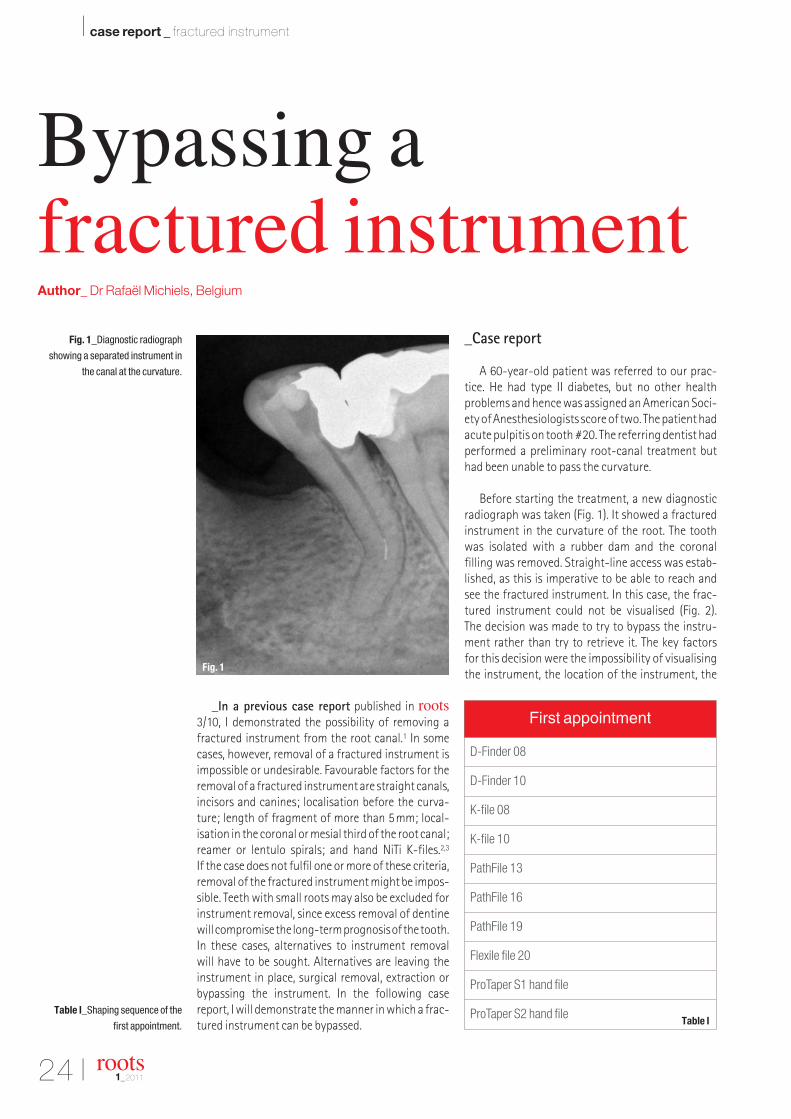
Before starting the treatment, a new diagnosticradiograph was taken (Fig. 1). It showed a fracturedinstrument in the curvature of the root. The toothwas isolated with a rubber dam and the coronal filling was removed. Straight-line access was estab-lished, as this is imperative to be able to reach and see the fractured instrument. In this case, the frac-tured instrument could not be visualised (Fig. 2). The decision was made to try to bypass the instru-ment rather than try to retrieve it. The key factors for this decision were the impossibility of visualising the instrument, the location of the instrument, the
Fig. 1_Diagnostic radiograph
showing a separated instrument in
the canal at the curvature.
roots1_2011
Bypassing a fractured instrumentAuthor_ Dr Rafaël Michiels, Belgium
First appointment
D-Finder 08
D-Finder 10
K-file 08
K-file 10
PathFile 13
PathFile 16
PathFile 19
Flexile file 20
ProTaper S1 hand file
ProTaper S2 hand fileTable I_Shaping sequence of the
first appointment.
Fig. 1
Table I
I 25
case report _ fractured instrument I
roots1_2011
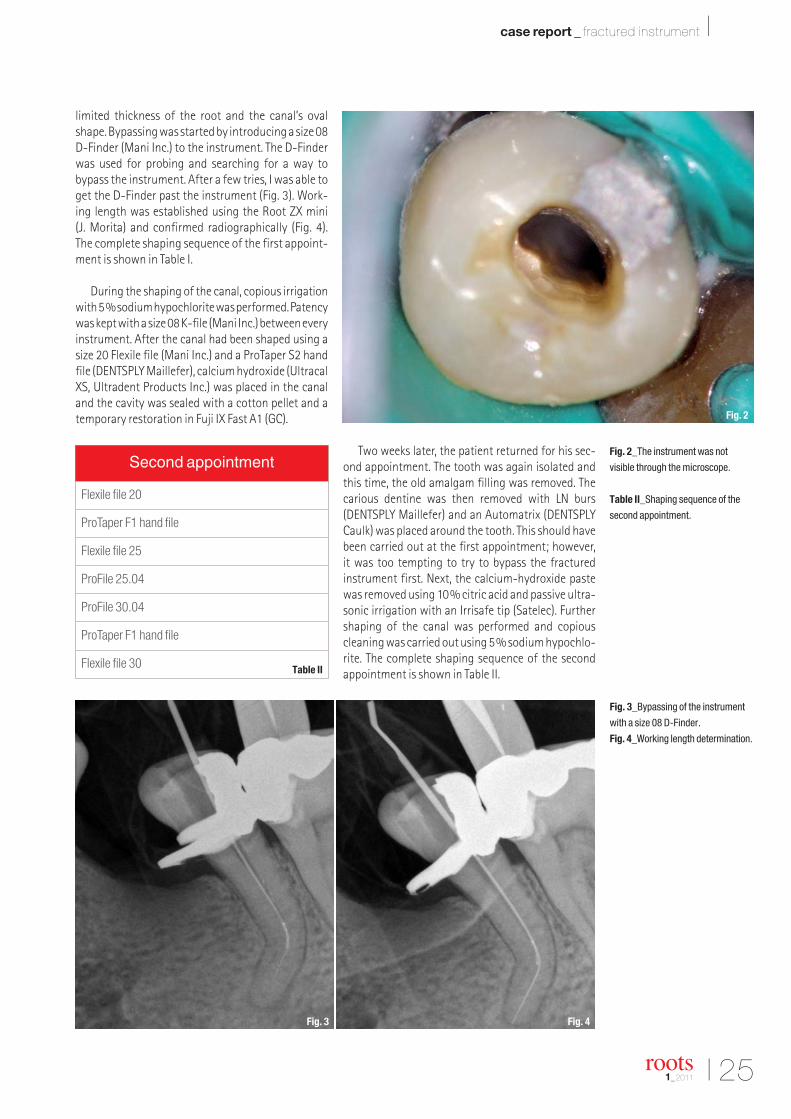
limited thickness of the root and the canal’s oval shape. Bypassing was started by introducing a size 08 D-Finder (Mani Inc.) to the instrument. The D-Finderwas used for probing and searching for a way to bypass the instrument. After a few tries, I was able toget the D-Finder past the instrument (Fig. 3). Work-ing length was established using the Root ZX mini (J. Morita) and confirmed radiographically (Fig. 4).The complete shaping sequence of the first appoint-ment is shown in Table I.
During the shaping of the canal, copious irrigationwith 5% sodium hypochlorite was performed. Patencywas kept with a size 08 K-file (Mani Inc.) between everyinstrument. After the canal had been shaped using asize 20 Flexile file (Mani Inc.) and a ProTaper S2 handfile (DENTSPLY Maillefer), calcium hydroxide (UltracalXS, Ultradent Products Inc.) was placed in the canaland the cavity was sealed with a cotton pellet and atemporary restoration in Fuji IX Fast A1 (GC).
Two weeks later, the patient returned for his sec-ond appointment. The tooth was again isolated andthis time, the old amalgam filling was removed. Thecarious dentine was then removed with LN burs(DENTSPLY Maillefer) and an Automatrix (DENTSPLYCaulk) was placed around the tooth. This should havebeen carried out at the first appointment; however, it was too tempting to try to bypass the fractured instrument first. Next, the calcium-hydroxide pastewas removed using 10% citric acid and passive ultra-sonic irrigation with an Irrisafe tip (Satelec). Furthershaping of the canal was performed and copiouscleaning was carried out using 5% sodium hypochlo-rite. The complete shaping sequence of the secondappointment is shown in Table II.
Fig. 3_Bypassing of the instrument
with a size 08 D-Finder.
Fig. 4_Working length determination.
Fig. 2_The instrument was not
visible through the microscope.
Table II_Shaping sequence of the
second appointment.
Second appointment
Flexile file 20
ProTaper F1 hand file
Flexile file 25
ProFile 25.04
ProFile 30.04
ProTaper F1 hand file
Flexile file 30
Fig. 2
Fig. 3 Fig. 4
Table II

26 I
I case report _ fractured instrument
The canal was shaped to an apical size of 30. Smear layer removal was performed with a rinse of10% citric acid. A final wash of the canal was carriedout with sterile saline. The canal was then dried withpaper points (Roeko). A 04 tapered gutta-perchacone was fitted into the canal.
Topseal (DENTSPLY Maillefer) was used as a root-canal sealer. After radiographical confirma-tion (Fig. 5), additional gutta-percha cones, ISO size20, were placed into the canal, according to the cold lateral condensation technique. Next, thegutta-percha was removed to about 5mm from theapex with the System B Elements Obturation Unit(Sybron Endo). Owing to the curvature, it was notpossible to go any deeper. Hence, I decided to create
a hybrid technique with cold lateral condensation.Finally, the backfill was done with the Elements Obturation Unit. After obturation (Fig. 6), a tempo-rary restoration in glass-io nomer cement (Fuji IXFAST A1, GC) was placed. Final radiographs weretaken, both parallel and angled (Figs. 7 & 8). Theprognosis of this case was excellent and the patientwas referred to his general dentist for a definitivecoronal restoration.
_Conclusion
Sometimes removal of a fractured instrument isimpossible or undesirable. In these cases, bypassingthe instrument is a valid alternative, which can leadto a favourable outcome as presented in this case._
Editorial note: A complete list of references is available
from the publisher.
roots1_2011
Dr Rafaël Michiels
graduated from the Depart-ment of Dentistry at GhentUniversity, Belgium, in 2006.In 2009, he completed thethree-year postgraduateprogramme in Endodonticsat the University of Ghent. He works in two private
practices limited to Endodontics in Belgium. He canbe contacted at [email protected] and viahis website www.ontzenuwen.be.
_about the author rootsFig. 5_Gutta-percha cone-fitting.
Fig. 6_The pulp chamber after
obturation with gutta-percha.
Fig. 7_Final radiograph (parallel).
Fig. 8_Final radiograph (angled).
Fig. 5
Fig. 7 Fig. 8
Fig. 6

implantsinternational magazine of oral implantology
I hereby agree to receive a free trial subscription of implantsinternational magazine of oral implantology (4 issuesper year).
I would like to subscribe to implants for € 44 includingshipping and VAT for German customers, € 46 including ship-ping and VAT for customers outside of Germany, unless a writ-ten cancellation is sent within 14 days of the receipt of the trialsubscription. The subscription will be renewed automaticallyevery year until a written cancellation is sent to OEMUS MEDIAAG, Holbeinstr. 29, 04229 Leipzig, Germany, six weeks prior tothe renewal date.
Last Name, First Name
Company
Street
ZIP/City/County
E-mail Signature
Signature
OEMUS MEDIA AGHolbeinstraße 29, 04229 Leipzig, Germany, Tel.: +49 341 48474-0, Fax: +49 341 48474-290, E-Mail: [email protected]
Reply via Fax +49 341 48474-290 to OEMUS MEDIA AG or via E-mail to [email protected]
Notice of revocation: I am able to revoke the subscription within 14 days after my order by sending a writtencancellation to OEMUS MEDIA AG, Holbeinstr. 29, 04229 Leipzig, Germany.
root
s 1/1
1
" Subscribe now!
You can also subscribe via www.oemus.com/abo
One issue free of charge!
Implants_Probeabo_A4_Implants_Abo_A4 09.03.11 18:26 Seite 1
28 I
I clinical technique _ WaveOne
_The new WaveOne NiTi file system fromDENTSPLY Maillefer is a SINGLE-use, SINGLE-file system to shape the root canal completely from startto finish. Shaping the root canal to a continuously tapering funnel shape not only fulfils the biologicalrequirements for adequate irrigation to rid the root-canal system of all bacteria, bacterial by-products andpulp tissue,1 but also provides the perfect shape for 3-D obturation with gutta-percha.2,3
In most cases, the technique only requires onehand file followed by one single WaveOne file to shapethe canal completely. The specially designed NiTi fileswork in a similar but reverse “balanced force” action4
using a pre-programmed motor to move the files in a back and forth “reciprocal motion”. The files are
manufactured using M-Wire technology, improvingstrength and resistance to cyclic fatigue by up tonearly four times in comparison with other brands ofrotary NiTi files.5
There are many dentists who, for whatever reason,are reluctant to use NiTi rotary instruments to preparecanals, despite the recognised advantages of flexibil-
ity, less debris extrusion and maintaining canalshape, amongst other advantages.6–8 For
them, the use of a single reciprocatingfile will be very attractive both in terms of
time and cost saving.
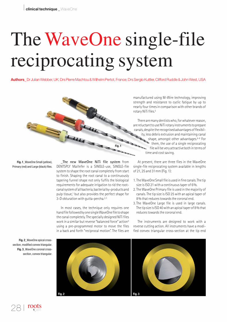
At present, there are three files in the WaveOnesingle-file reciprocating system available in lengthsof 21, 25 and 31mm (Fig. 1):
1. The WaveOne Small file is used in fine canals. The tipsize is ISO 21 with a continuous taper of 6%.
2. The WaveOne Primary file is used in the majority ofcanals. The tip size is ISO 25 with an apical taper of8% that reduces towards the coronal end.
3. The WaveOne Large file is used in large canals. The tip size is ISO 40 with an apical taper of 8% thatreduces towards the coronal end.
The instruments are designed to work with a reverse cutting action. All instruments have a modi-fied convex triangular cross-section at the tip end
Fig. 1_WaveOne Small (yellow),
Primary (red) and Large (black) files.
Fig. 2_WaveOne apical cross-
section, modified convex triangular.
Fig. 3_WaveOne coronal cross-
section, convex triangular.
roots1_2011
The WaveOne single-filereciprocating systemAuthors_Dr Julian Webber, UK; Drs Pierre Machtou & Wilhelm Pertot, France; Drs Sergio Kuttler, Clifford Ruddle & John West, USA
Fig. 2 Fig. 3
Fig. 1

I 29
clinical technique _ WaveOne I
roots1_2011
(Fig. 2) and a convex triangular cross-section at thecoronal end (Fig. 3). This design improves instrumentflexibility overall. The tips are modified to follow canalcurvature accurately. The variable pitch flutes alongthe length of the instrument considerably improvesafety (Fig. 4).
Because there is a possibility of cross-contamina-tion associated with the inability to completely cleanand sterilise endodontic instruments9 and the possi-ble presence of prion in human dental pulp tissue,10 allinstruments used inside root canals should be singleuse.11 WaveOne instruments are a new concept in thisimportant standard of care, as they are truly singleuse. The plastic colour coding in the handle becomesdeformed once sterilised, preventing the file from being placed back into the handpiece.
The recommendation for single use has the addedadvantage of reducing instrument fatigue, which isan even more important consideration with WaveOnefiles, as one file does the work traditionally performedby three or more rotary NiTi files.
The WaveOne motor (Fig. 5) is rechargeable batteryoperated with a 6:1 reducing handpiece. The pre-pro -grammed motor is set for the angles of reciprocationand speed for WaveOne instruments. The counter-clockwise (CCW) movement is greater than the clock-wise (CW) movement. CCW movement advances the instrument, engaging and cutting the dentine.CW movement disengages the instrument from thedentine before it can (taper) lock into the canal. Three
reciprocating cycles complete one complete reverserotation and the instrument gradually advances intothe canal with little apical pressure required.
All brands of NiTi files can be used with theWaveOne motor, as it has additional functions forcontinuous rotation. However, as WaveOne files have their own unique reverse design, they can ONLYbe used with the WaveOne motor with its reverse reciprocating function.
The WaveOne technique involvesthe following stages:
1. straightline access, acceptedprotocol;
2. WaveOne file selection;3. single-file shaping;4. copious irrigation with 5% NaOCl
and EDTA before, during and aftersingle-file shaping.
_WaveOne file selection and clinicalprocedure (Figs. 6–8)
Whilst a good preoperative periapical radiographwill give an indication of what to expect before the canal is prepared (size and length of the canal,number of canals, degree and severity of curvature),
Fig. 4_WaveOne variable pitch flute
increases safety.
Fig. 5_WaveOne motor and 6:1
reducing handpiece.
Figs. 6–8_WaveOne Small, Primary
and Large files with their respective
file selection and clinical procedural
flow chart.
Fig. 6 Fig. 7 Fig. 8
Fig. 4
Fig. 5

30 I
I clinical technique _ WaveOne
only the first hand file into the canal will aid in the selection of the WaveOne file as follows:
1. If a 10 K-file is very resistant to movement, useWaveOne Small file.
2. If a 10 K-file moves to length easily, is loose or veryloose, use WaveOne Primary file.
3. If a 20 hand file or larger goes to length, useWaveOne Large file.
Single-file shaping
1. take hand file into canal and watch-wind to lengthor resistance (approximately two-thirds of canallength);
2. use appropriate WaveOne file to approximatelytwo-thirds of canal length;
3. irrigate copiously;4. take hand file to length and confirm with an apex
locator and radiograph;5. take WaveOne file to length;
6. confirm foramen diameter with hand file the samesize as WaveOne file; if snug, preparation is complete;
7. if foramen diameter is larger than WaveOne file,consider the next larger WaveOne file;
8. majority of cases will be completed with WaveOnePrimary file.
Guidelines for use
1. use WaveOne files with a progressive up and downmovement no more than three to four times, onlylittle force is required;
2. remove file regularly, wipe clean, irrigate and con-tinue;
3. if file does not progress, confirm patent canal andconsider using a smaller WaveOne file;
4. whilst glide path management is minimal withWaveOne shaping files, some practitioners will bemore comfortable if the glide path is first securedwith PathFiles (DENTSPLY Maillefer);
5. in severely curved canals, complete apical pre -paration by hand if reproducible glide path is notpossible;
6. WaveOne files can be used to relocate the canal orifice and expand coronal shape; even in a recip-rocating motion use them with a “brushing” actionshort of length to achieve this;
7. never work in a dry canal and constantly irrigatewith NaOCl and later EDTA;
8. as preparation time is short, activate the irrigatingsolutions to enhance their effect; the EndoActivator(DENTSPLY Maillefer) is ideal for this (Fig. 9).12
WaveOne obturating solutions
Obturation of the root-canal system is the finalstep of the endodontic procedure. The WaveOne system includes matching paper points, gutta-percha points and Thermafil WaveOne obturators(Figs. 10–12). The matching gutta-percha points can be used in conjunction with the Calamus Dual 3-D Obturation System (DENTSPLY Maillefer; Fig. 13)as demonstrated in the following cases.
Fig. 9_EndoActivator irrigation device.
Fig. 13_Calamus Dual 3-D
Obturation System.
Fig. 10_WaveOne matching
paper points.
Fig. 11_WaveOne matching
gutta-percha points.
Fig. 12_WaveOne matching
Thermafil obturators.
roots1_2011
Fig. 13Fig. 9
Fig. 10
Fig. 11
Fig. 12

I 31
clinical technique _ WaveOne I
roots1_2011
_Case studies
Case I (Figs. 14a–c)
Tooth #36 presented with symptoms of irre-versible pulpitis and early apical periodontitis. Initialradio graphic assessment showed four narrow andcurved canals. Access was made and all canals wereworked to length with a 10 K-file. A WaveOne Primaryfile (25.08) was selected and length was reconfirmedwith a 10 K-file. The WaveOne Primary file was workedto length in all four canals. Obturation was done withwarm vertical condensation (WVC) using CalamusDual.
Case II (Figs. 15a–c)
Tooth #16 had symptoms of acute pulpitis with atemporary filling, covering exposure distally, as wellas severe curvature of the mesiobuccal (MB) canalsand apically in the distal canal. K-files 8 and 10 were
taken to length in all the canals. A WaveOne Primaryfile (25.08) was selected. Length was confirmed witha 10 K-file. The WaveOne Primary file was taken tolength in all the canals. Obturation was done withWVC using Calamus Dual.
Case III (Figs. 16a–c)
Tooth #17 presented with radiographic evidenceof apical periodontitis and was non-vital. The canalswere hardly visible on the preoperative X-ray. Primaryconsideration would have been a WaveOne Small file(21.06). In all canals, the 8 K-file moved to length easily. The 10 K-file also moved to length but wastight.
A WaveOne Primary file (25.08) was selected andtaken to approximately three-quarters of the length.Recapitulation was achieved with a 10K-file to length.The WaveOne Primary was taken to length in all thecanals and the canals were then obturated with WVC.
Figs. 14a–c_Pre-op radiograph of
#36 showing narrow and curved
canals (a). Post-op radiographs:
Canals were shaped with a WaveOne
Primary file and filled with
gutta-percha with WVC (b & c).
Figs. 15a–c_Pre-op radiograph of
#16 showing severely curved MB and
DB canals (a). Post-op radiographs:
Canals were shaped with a WaveOne
Primary file and filled with
gutta-percha with WVC (b & c).
Figs. 16a–c_Pre-op radiograph of
#17 with canals hardly visible (a).
Post-op radiographs: Canals were
shaped with a WaveOne Primary file
and filled with gutta-percha with WVC
(b & c).
Figs. 17a–c_Pre-op radiograph of
#17 with canals barely visible and
#15 with a quite large canal (a).
Post-op radiographs: #17 canals
were shaped with a WaveOne Primary
file. #15 canal was shaped with a
WaveOne Large file. All canals were
filled with gutta-percha with WVC
(b & c).
Fig. 14a Fig. 14b Fig. 14c
Fig. 15a Fig. 15b Fig. 15c
Fig. 16a Fig. 16b
Fig. 17b
Fig. 16c
Fig. 17a Fig. 17c

32 I
I clinical technique _ WaveOne
Case IV (Figs. 17a–c)
Tooth #16 presented with radiographic evidenceof asymptomatic apical periodontitis. The canals werehardly visible on the preoperative X-ray. The MB canalwas severely curved, and the distobuccal (DB) andpalatal canals were not visible. A 10 K-file moved tolength easily in the MB and DB canals. In the palatalcanal, 10 and 15 K-files moved to length easily. AWaveOne Primary file (25.08) was selected for allcanals. Lengths were confirmed and the canals wereshaped to length with WaveOne files.
In tooth #15, a large, single canal was clearly visi-ble. 20 and 25 K-files went to length and a WaveOneLarge file (40.08) was selected. Canal length was con-firmed and the WaveOne Large file was used to shapethe canal.
_Advantages of the WaveOne file reciprocating system
1. only one NiTi instrument per root canal and in mostcases per tooth;
2. lower cost;3. less instrument separation owing to the unique
reciprocating movement that will prevent and/ordelay the instrument advancing from plastic defor-mation to its plastic limit;
4. decreases global shaping time, allowing the clini-cian to spend more time cleaning the root-canalsystem with enhanced irrigation techniques;
5. eliminates procedural errors by using a single instrument rather than using multiple files;
6. a new standard of care, eliminating the possibilityof prion contamination owing to single use;
7. easy to learn;8. easy to teach.
_WaveOne research
The Nova Southeastern University College of Den-tal Medicine in the USA is conducting research intoWaveOne. The following areas of research, amongstothers, are being investigated using micro-focus CTscanning technology, which provides remarkable in-sight into:
1. canal-centring ability of WaveOne13 (Figs. 18a–c);2. remaining canal wall thickness after instrumenta-
tion with WaveOne;14
3. final shape versus initial shape of the canal withWaveOne;15
4. canal wall cleanliness with WaveOne16 (Figs. 19a–c).
Other areas of research are flexibility,17 fatigue18
and debris extrusion.19 To date, the results of thesestudies suggest that WaveOne single reciprocatingfiles are comparable in performance to all the majorleading brands of NiTi files that operate in continuousrotation.
_Conclusion
The WaveOne system is an exciting new concept inthe preparation of the root canal. Whilst currentteaching advocates the use of multiple NiTi files ofdifferent diameter and taper to gradually enlarge the root canal, only one WaveOne single shaping fileis required to prepare the canal to an adequate sizeand taper, even in narrow and curved canals.
However, along with this, there must be a caveat.WaveOne files only shape the canal, extremely quicklyin many instances, but they do not clean the rootcanal. It is the duty of teachers, clinicians and manu-facturers to emphasise the role and importance of
Figs. 18a–c_Micro-focus CT scan at
coronal level (a), mid-root level (b)
and apical level (c) of the
mesial canals of the lower first molar
demonstrates the excellent centring
and shaping ability of the WaveOne
Primary file.
Figs. 19a–c_A SEM representative
sample at coronal level (a), mid-root
level (b) and apical level (c) of the
canal wall, showing excellent
cleanliness and open dentinal
tubules after shaping with
a WaveOne Primary file and assisted
irrigation with the EndoActivator.
roots1_2011
Fig. 18a Fig. 18b Fig. 18c
Fig. 19a Fig. 19b Fig. 19c

I 33
clinical technique _ WaveOne I
roots1_2011
irrigation as a major determinant of endodontic success. Once it is fully appreciated that shaping and cleaning the root-canal system are irrevocably intertwined, then endodontics will be easier for alland available to all, and WaveOne will truly becomethe root-canal preparation instrument of the future.
Drs Julian Webber, Pierre Machtou, Wilhem Pertot,Sergio Kuttler, Clifford Ruddle and John West where involved in the development, field testing and researchassociated with WaveOne._
_References
1. Sjogren U, Figdor D, Persson S, Sundqvist G. Influence of in-fection at the time of root filling on the outcome of endodon-tic treatment of teeth with apical periodontitis. Int Endod J1997; 30(5): 297–306.
2. Schilder H. Cleaning and shaping the root canal. Dent ClinAmer 1974; 18(2): 269–96.
3. West JD. Endodontic predictability—“Restore or remove:how do I choose?” In: Cohen M, ed. Interdisciplinary Treat-ment Planning: Principles, Design, Implementation. Quin-tessence Publishing Co., 2008:123–64.
4. Roane JB, Sabala CL, Duncanson MG. The “balanced force”concept for instrumentation of curved canals. J. Endod1985; 11(5): 203–11.
5. Johnson E, Lloyd A, Kuttler S, Namerow K. Comparison be-tween a novel nickel titanium alloy and 508 Nitinol on thecyclic fatigue life of Profile 25/.04 rotary instruments. J En-dod 2008; 34(11): 1406–9.
6. Walia HM, Brantley WA, Gerstein H. An initial investigation onthe bending and torsional properties of Nitinol root canalfiles. J Endod 1998; 14(7): 340–51.
7. Reddy SA, Hicks ML. Apical extrusion of debris using twohand and two rotary instrumentation techniques. J Endod1998; 249(3): 180–3.
8. Pettiette MT, Delano EO, Trope M. Evaluation of success rateof endodontic treatment performed by students with stain-less steel K files and nickel titanium hand files. J Endod2001; 27(2): 124–7.
9. Letters S et al. A study of visual and blood contamination onreprocessed endodontic files from general dental practice.Brit Dent J 2005; 199: 522–5.
10. Schneider K, Korkmaz Y, Addicks K, Lang H et al. Prion Pro-tein (PrP) in human teeth: an unprecedented pointer to PrP’sfunction. J Endod 2007; 33(2): 110–3.
11. Department of Health (UK). Advice for dentists on the re-useof endodontic instruments and variant Creutzfeldt-JacobDisease (vCJD). April 2007.
12. Ruddle CJ. Endodontic disinfection: tsunami irrigation. EndoPrac. 2008;11:7–16.
13. Kuttler S, Bonilla C, Perez R, Hardigan P. Evaluation of re-maining canal wall thickness and center ability after instru-mentation with a new reciprocating system. 2011a. Inpress.
14. Webber J, Kuttler S, Bonilla C, Perez R, Hardigan P. Evalua-tion of remaining canal wall thickness and center ability af-
ter instrumentation with WaveOne reciprocating system vsrotary BioRace NiTi system. 2011b. In press.
15. Pertot W, Machtou M, Kuttler S, Bonilla C, Perez, R, HardiganP. Evaluation of remaining canal wall thickness and centerability after instrumentation with WaveOne reciprocatingsystem vs Revo-S rotary NiTi system. 2011. In press.
16. Machtou P, Kuttler S, Bonilla C, Pertot W, Perez R, HardiganP. Evaluation of canal wall cleanliness after instrumentationwith four nickel titanium rotary file systems and one recip-rocating system. 2011. In press.
17. McLean R, Kuttler S et al. Evaluation of the flexibility of 4nickel titanium rotary file systems and one reciprocating filesystem. 2011. In press.
18. Coil J, Shen Y, Kuttler S, Bonilla C, Ruddle C, West J, Rigob-erto P, Hardigan P. 2011. In press.
19. Armando L, Kuttler S, Bonilla C, Webber J, Machtou P, Per-tot W, Perez R, Hardigan P. Comparison of the extruded de-bris of a new nickel titanium reciprocating file versus fourconventional rotary systems. Jan 2011. In press.
Dr Julian Webber hasbeen a practising endodon-tist in London, England, forover 30 years. He was thefirst UK dentist to receive aMaster’s degree in Endo -dontics from a university in the USA (NorthwesternUniversity Dental School,
Chicago) in 1978. He has lectured extensively andgiven many hands-on courses on endodonticsworldwide. He has written in numerous peer-reviewed journals and contributed numerouschapters in endodontic texts. Dr Webber is a formerPresident of the British Endodontic Society, a fac-ulty member of the Pacific Endodontic ResearchFoundation in San Diego, Honorary Professor at theUniversity of Belgrade, Serbia, and an HonoraryMember of the Ukrainian Medical and Stomatolog-ical Academy. He is a fellow of the InternationalCollege of Dentists and an active member of theAmerican Association of Endodontists. He is theeditor of Endodontic Practice (UK) and a boardmember of many prestigious dental journals.
Dr Julian Webber
The Harley Street Centre for Endodontics121 Harley StreetLondon W1G 6AXEngland
_about the lead author roots

34 I
I clinical technique _ R-phase
_Every dentist and endodontist dreams that allroot canals could be straight and large. Unfortunately,in reality they are often everything but. On a daily basis, we are faced with new challenges in curved andnarrow root canals. While NiTi rotary files havechanged our world significantly, our first experienceswere not so encouraging.
We were faced with file separation owing toanatomical considerations of the root-canal systemand our poor knowledge of the files, the alloy and theway to use the files properly.
Much research has been conducted in order to bet-ter understand the properties of the alloy and the files.Researchers have used a torque metre to study the files(Fig. 1). However, we realised that different data was required with regard to stressed or used files. Furtherresearch demonstrated that the yield, which is thepoint beyond the austenite phase, is stable regardlessof the dimension and the size of the file (Figs. 2 & 3). The major difference is in the torque value and the behaviour of the martensite phase. Deformation in themartensite phase is irreversible and leads to file sepa-ration. Some file deformation can be seen clinically andit is a safety property of files that they have a longer de-formation period under stress in the martensite phase.
There are two types of clinical stresses on a file incurved canals: bending and torsional stress (Figs. 4 & 5). Bending stress occurs when the file passes insidea curve and is subjected to stresses at an equal level:stretching on the outer part of the curve and com-pression of the alloy structure from the internal partof the curve. This kind of stress cannot break a file, butit can lower its torsional stress by at least 30% fromthe first few seconds that the file is active inside thecurve.
Fig. 1_Graph showing the stress test
result of a K3 file conducted with a
torque metre. It shows
the austenite phase, yield point and
the martensite plateau before file
separation.
Figs. 2 & 3_Graphs showing the
difference between stress cycle #1
(Fig. 2) and 10 (Fig. 3). The yield is
fairly stable and the austenite phase
decreased in torque value.
roots1_2011
R-phase advantagesin shaping curvesAuthor_ Dr Philippe Sleiman, Lebanon
Fig. 1
Fig. 2 Fig. 3

I 35
clinical technique _ R-phase I
roots1_2011
Torsional stress is more dangerous. It occurs whenthe tip or any other section of the file is locked insidethe canal while the rest of the file is still rotating. Thiscan lead to instant file separation. Torsional stress canoccur anywhere inside the canal and can be even moredangerous when it is combined with bending stressesinside the curvature of the canal (Fig. 5). This can bethe perfect trap for rotary files.
Combining the two essential features of a file—security and flexibility—was not possible with the NiTi alloy available. Therefore, some manufacturersfocused on the flexibility of the files while compro-mising security, and others focused on security while compromising flexibility. Intensive researchwas conducted into changing the crystalline struc-ture and obtaining a dual-phase structure as its maincharacteristic. The dual phase is a mix of austenite andthe R-Phase. The R-phase has the advantage of beingable to cope with increased pressure while increasingthe torque value (Fig. 6). It appears after the austenitephase and still increases in torque until the ultimate
deformation point. There is then a short martensitephase prior to separation. During the R-phase, thereare actually two kinds of R-phases: R1 and R2. Ac-cording to thermal cycling tests under various con-stant stresses, the transformation strain of R2 isgreater than that of R1. With constant stress increas-ingly applied, the latter strain increases and the formerdecreases. However, the total strain of both R1 and R2is almost constant irrespective of the amount of stress.R1 will start immediately after austenite, and then R2will take over in the middle of the transition area untilthe ultimate deformation point, where martensite willbe formed. With the R-phase, shaping curves will bemuch easier and safer as the files produced with themodified NiTi alloy are much more flexible than anyother file with the same dimensions. This allows the fileto cope with the pressure of shaping the curves safely.
As for the clinical applications, we must ensurethat we do not place a very large file in a curve, suchas a 0.10 or 0.08 taper, but pay attention to the sever-ity of the curves, for two reasons:
Fig. 4_Illustration of the bending
stress to which a file is subjected
inside the curve.
Fig. 5_Illustration of the torsional
stress and the load of stress that a file
will take at the tip of the root canal or
inside the curve, which will lead to
file separation.
Fig. 6_Graph showing the stress
test result of a TF file using a torque
metre.
Fig. 7_M4 handpiece.
Fig. 4 Fig. 5
Fig. 6 Fig. 7

36 I
I clinical technique _ R-phase
1. in order to avoid a taper lock, which can lead to fileseparation or damage in severely curved canals;and
2. in order to avoid a strip perforation caused by aggression of the files.
We must carefully analyse the preoperative X-rayto determine the location of the curve. This can beachieved by inserting a size 10 K-file, which will takethe impression of the canal. It gives us a good idea ofthe curve or curves, as well as the shape of the canal,thereby helping us determine a strategy regarding the depth to which we can go with our large files andthen switch to a lesser taper. This is a simple clinical tipthat is helpful in avoiding serious complications inshaping curved canals.
The sequence I personally follow with Twisted Files(TF; SybronEndo) is as follows. After checking root-canal patency and taking the impression of the canalwith a size 10 K-file, I use my M4 handpiece with a size20 SS file for 15 seconds in each canal (Fig. 7). It doesnot have to go to length. I only take it as deep as it willgo with a simple push and pull movement and usesizes 15 and 10 SS files, if required, after the size 20 in a crown-down method. After achieving patency, I use the rotary files in order to clean and shape theroot-canal system. I start with a size 25 with taper0.08, taking it to the beginning of the curve. I limit itsinsertion to this point. I then usually switch to a size25 TF with taper 0.06, depending on the severity of thecurve. If the curve is normal to medium, a size 25 TFwith taper 0.06 should be able to enlarge it safely. If
the curve is severe, which will show on the size 10 K-files and from the resistance of the previous file, I usea size 25 TF with taper 0.04 to full working length. Theapical enlargement will follow the crown-down,which has opened a safe way to the apical area, or the last 3 mm for enlargement. I use a size 40 TF withtaper 0.04 whenever I am able to for optimal cleaningof the apical area, as well as for reducing the colonyformation unit and preparing the dentine for obtura-tion using RealSeal (SybronEndo) according to properirrigation protocol.
Achieving step-by-step root-canal preparation isthe gold standard of care that we can offer to our patients without any negative surprises along theway. Respecting a few simple rules and not lettingourselves be carried away by our temptation to workmore quickly can lead to excellent clinical results.
I would like to thank Yulia Vorobyeva, interpreterand translator, for her help with this article._
roots1_2011
Ass. Prof. Philippe Sleiman
Dubai Sky Clinic
Burjuman Business Tower, Level 21
Trade Center Street, Bur Dubai
Dubai, UAE
_contact roots
Figs. 8–11_Clinical cases.
Fig. 8 Fig. 9
Fig. 10 Fig. 11

Projekt2 24.02.11 17:10 Seite 1

38 I
I feature _ interview
_The dental supplier SycoTec, headquartered in Leutkirch in Germany, acquired MICRO-MEGA, aFrench company with a long-standing tradition of excellence, in autumn of 2009. In February 2010, theCanadian company SciCan joined the duo. The mergerof SycoTec, MICRO-MEGA and SciCan formed theSanavis Group, which is now one of the ten largestsuppliers of dental equipment worldwide. ExecutiveChairman Dr Martin Rickert spoke with roots aboutthese new developments.
_roots: Dr Martin Rickert, what does the nameSanavis mean and what new tasks has the mergerbrought to the group?
Dr Martin Rickert: The word sanavis is borrowedfrom Latin and, simply translated, means “health andstrength”. The name is meant to illustrate that thegroup consists of companies whose main businesssegment is dental products designed to enable dentists and, consequently, patients to attain andmaintain good oral health. Contemporary and inno-vative products are the foundation of our companystrategy. Our main task is gradual orientation towardsa joint fundamental strategy and the development ofjoint processes so that our customers can directlybenefit from the advantages of this merger.
_Which advantages do you see resulting from thismerger?
First of all, we are able to offer our customers animproved service. With a much greater regional pres-ence, our customers now receive a far more regionaland consequently more individualised service.
Furthermore, we are now able to coordinate salesof the individual companies much more effectively,thus making them more attractive to our customers.This will also affect the product development processand, in turn, lead to products that enable improvedcourses of treatment. Internally, we will be able tobenefit from clear advantages in production, pur-chasing, logistics, administration and reporting.
_What are the individual companies going to focus on and which role will they play within theSanavis Group?
Ergonomics and safety are the key features of allour future products. In this context, ergonomicsmeans enabling the person providing the treatmentto work as simply, efficiently and carefully as possible.Safety refers to minimising the potential for errorduring the course of the treatment and to the widefield of infection control.
MICRO-MEGA is our endodontic specialist, offer-ing everything from root-canal instruments to fillingmaterials. SciCan is our infection-control specialist,covering general practice hygiene, instrument sterili-sation and infection control during treatment. Bothcompanies have similar needs with regard to dentaldrive technology. Simply put, this term refers to tech-nologies and products that make devices rotate ormove, such as micro-motors, handpieces and turbines.SycoTec, an expert original equipment manufacturer,is our specialist in this.
_Let’s look at the individual companies. MICRO-MEGA, the French manufacturer of high precisiontools for root-canal treatments, has been settingworld standards on the international dental marketfor over 100 years. Which product is considered to bestate of the art at the moment?
With the Revo-S system for root-canal preparation,MICRO-MEGA undisputedly has the right to claim a pioneering role once again. Revo-S is a NiTi instrumentsystem that offers unparalleled ease of handling for the practitioner with maximum protection against filebreakage. The root canal can be prepared in a clever sequence with only three files. Easy-to-use upgradesare also available for complicated canal shapes. Thissystem is a good example of the advantage of MICRO-MEGA’s many years of experience in endodontics.
_... and SciCan complements the range of productswith its full spectrum of infection-control solutions.
Dr Martin Rickert,
Executive Chairman Sanavis Group
roots1_2011
“Our goal is to offer solutionsand products with a definitebenefit for the practitioner”An interview with Dr Martin Rickert, Executive Chairman Sanavis Group

I 39
feature _ interview I
roots1_2011
And the timing is excellent considering that the legal regulations with regard to infection control are increasingly becoming more stringent!
Infection control is becoming increasingly impor-tant, not only as a result of the regulatory require-ments. SciCan offers complete solutions from A to Z.Dentists can rely on over 50 years of experience,which has led to products that offer maximum efficiency, consistency and safety. The rapid steriliserStatim is a great example. While it is easy to handle,economic and functional, its short cycle time is unri-valled. Furthermore, the new thermal disinfector Hydrim impresses with its simple installation andeconomic operation. Naturally, all products adhere to all regulatory requirements.
_Owing to the financial and economic crisis, manycompanies have struggled to maintain their positionin the international markets. Do you feel well posi-tioned as a result of the merger?
In the difficult macroeconomic environment we have been experiencing in recent years, it is an advantage to be part of a strong group. We thereforefeel very well equipped for the future, not only interms of purely economic aspects, but also generallywith regard to our future business. Our goal is to offer solutions and products with a definite benefitfor the practitioner. Being a strong group makes thiseasier and provides greater future security.
_MICRO-MEGA and SciCan are internationallyrecognised brands that are constantly investing in research and development. The Sanavis Group is nowa global player. How do you intend to take advantageof this?
Even though we have reached the size of a globalplayer, we will continue to structure our business locally. However, we will now make use of our expanded network in the respective local branches.This applies to our research partners, as well as to salesand service. Moreover, we can now also tackle new developments that would have been too large for theindividual companies. The main advantage surely isthat we are now able to access the expertise of thepartner companies for new developments. In the future, products will become increasingly digitalisedand integrated, making the integration of different
product areas indispensable. A great deal can be expected of us in this respect.
_How will customer service be organised?Customer service will be organised at local level, as
has been the case up to now. Naturally, we will con-tinue our existing, reliable partnerships. Furthermore,our customers can look forward to an extension of theservices offered, as we are improving our presence forour entire product range, particularly in the Germanmarket.
_Will the Sanavis Group appear under one um-brella at trade fairs and exhibitions in future?
Yes, this will be the case at the larger trade fairs,such as the IDS. However, a joint umbrella does notmean that the name Sanavis will be at the fore. MICRO-MEGA and SciCan will continue to form thebackbone of the trade fair presence. However, thebrands will exhibit at a joint booth.
_Which products will be in focus during the IDSand what new innovations can we expect?
We have already strengthened our developmentefforts and look forward to being able to present alarge number of new products. These new develop-ments include a new, rapid steriliser and advancedthermal disinfectors. We will also present new root-canal fillers. In the field of drive systems, visitors willbe able to see a whole range of innovations, such asnew micro-motors, handpieces and contra-anglehandpieces, as well as motors with an innovative ergonomic design. I believe that never before have we been able to present such an explosion of inno -vations!_
“Moreover, we can now also tackle new developments that
would have been toolarge for the individual
companies.”

40 I
I industry report _ Calamus Dual 3D Obturation System
_Virtually all dentists are intrigued by endo -dontic post-treatment radiographs exhibiting filledaccessory canals. Filling root-canal systems repre-sents the culmination and successful fulfilment of a series of procedural steps that comprise start-to-finish endo dontics (Fig. 1). Although the excitementasso ciated with the so-called thrill-of-the-fill is understandable, scientific evidence should supportthis enthusiasm. Moving heat-softened obturationmaterials into all aspects of the anatomy is depend-ent on eliminating pulpal tissue, the smear layer and
related debris, and bacteria and their by-products,when present. In order to maximise obturation potential, clinicians would be wise to direct treatmentefforts toward shaping canals and cleaning root-canal systems.1
Shaping facilitates 3-D cleaning by removing restrictive dentine, allowing a more effective volumeof irrigant to penetrate, circulate and potentiallyclean into all aspects of the root-canal system (Fig. 2).Well-shaped canals result in a tapered preparationthat serves to control and limit the movement ofwarm gutta-percha during obturation procedures.Importantly, shaping also facilitates 3-D obturationby allowing pre-fit pluggers to work deeply and unre-stricted by dentinal walls and move thermo-softenedobturation materials into all aspects of the root-canal system. Improvement in obturation potential islargely attributable to the extraordinary technolo -gical advancements in shaping canals and cleaningand filling root-canal systems.2,3
This article features the new Calamus Dual 3D Obturation System (DENTSPLY Maillefer; Fig. 3) thatmay be used to fill root-canal systems. Schilder described the classic vertical condensation techniquemore than forty years ago.4 Over time, a few different,yet similar, warm gutta-percha techniques haveevolved. The purpose of this article is to describe the Calamus Dual 3D Obturation System and the
Fig. 1_A post-op film of a mandibular
first molar demonstrates the
importance of shaping canals
and cleaning and filling root-canal
systems.
Fig. 2_This animation supports the
scientific evidence that shaped
canals enhance the active exchange
of irrigant into all aspects of the
root-canal system.
Fig. 3_The Calamus Dual 3D
Obturation System combines a Pack
handpiece for down-packing with the
Flow handpiece for back-packing.
roots1_2011
Filling root-canal systems—The Calamus 3D ObturationTechniqueAuthor_ Dr Clifford J. Ruddle, USA
Fig. 2 Fig. 3
Fig. 1

I 41
industry report _ Calamus Dual 3D Obturation System I
roots1_2011
manner in which to use this technology to performthe vertical condensation technique. The clinician isencouraged to read, visualise and learn more aboutthe manner in which to perform each procedural step that directly serves to influence filling root-canalsystems; this includes performing the other hybridwarm gutta-percha techniques using Calamus tech-nology.1,5
_Vertical condensation technique
The objective of the vertical condensation tech-nique is to carry a wave of warm gutta-percha alongthe length of the master cone continuously and progressively, starting coronally and ending in apicalcorkage (Fig. 4). The physical and thermo-molecularproperties of gutta-percha are well understood andhave been clearly described in a series of ground-breaking articles published decades ago.6–10 The content of these scientific articles provides insight,understanding and reference for the clinical andtechnical description that follows. While I have previously described the vertical condensation tech-nique,11,12 this article represents the most recent advances in the manner in which to perform the warmgutta-percha with vertical condensation technique.
Cone fit and plugger selection
Traditionally, a medium-sized non-standardisedgutta-percha master cone was selected and apicallytrimmed to fit snugly into the terminus of the prepared canal. The 6% taper of these master cones,as compared to the 2% taper of standardised gutta-percha, ensured more effective hydraulics during obturation. Today, the selection of the correct mastercone has been simplified because of the rediscoveryof system-based endodontics. System-based mastercones streamline treatment in that they are intendedto have an apical diameter the same as and a rate of taper slightly less than the largest manual or mechanically driven file that was carried to the fullworking length.
The master cone is fitted in a fluid-filled canal tosimulate more closely the lubrication effect that
sealer will provide when sliding the buttered mastercone into the prepared canal. Further, the master cone should be able to be inserted to the full workinglength and exhibit apical tug-back upon removal. This master cone can be apically trimmed and furthercustomised with glass slabs or a spatula, utilising either cold or heat rolling techniques. It is simple to fita master cone into a patent, smoothly tapered andwell-prepared canal.
A diagnostic working film should confirm the desired position of the master cone and verify all theprevious operative steps. The master cone is typicallycut back about 1.0mm from the radiographic terminus so that its most apical end is just short of the apical constriction or the actual position of thephysiologic terminus (PT; Figs. 5a & b). Specifically, the final length of any given prepared and finishedcanal is the reproducible distance from the referencepoint to the PT. Fortuitously, the position of the most apically instrumented foramen can be consistentlylocated utilising the paper point drying technique.12
Four manual pluggers, utilised to compact heat-softened gutta-percha, provide working end diameters of 0.5mm, 0.7mm, 0.9mm and 1.3mm(DENTSPLY Maillefer). Generally, a larger-sized plugger
Fig. 4_A post-op film of a maxillary
second molar. Note the abrupt apical
curvature of the palatal system,
recurvature of the DB system and
the filled furcal canal.
Figs. 5a & b_These animations
demonstrate the master cone fitted
to length and the master cone
apically cut-back based on the
paper point drying technique.
Fig. 6_The EHP that will loosely fit
through the straightaway portion of
the canal and optimally to within
5 mm from the full working length
is selected.Fig. 5b Fig. 6
Fig. 4
Fig. 5a
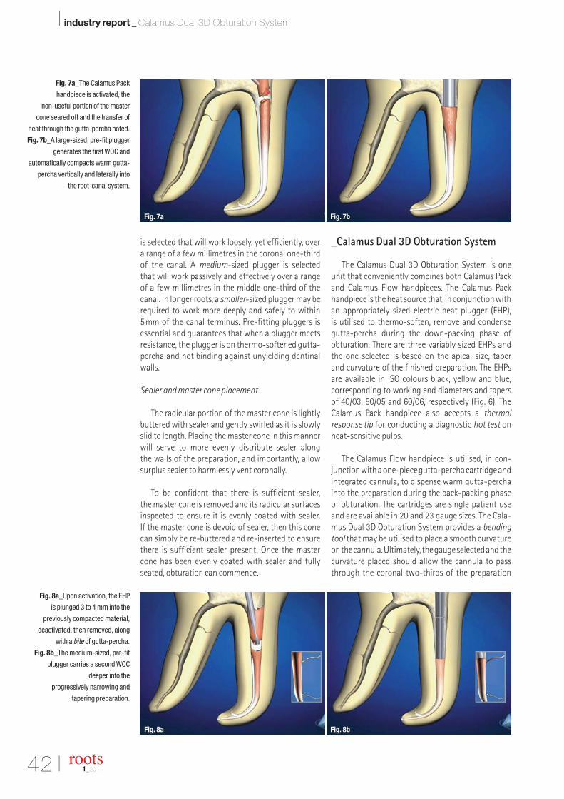
42 I
I industry report _ Calamus Dual 3D Obturation System
is selected that will work loosely, yet efficiently, over a range of a few millimetres in the coronal one-thirdof the canal. A medium-sized plugger is selected that will work passively and effectively over a range of a few millimetres in the middle one-third of thecanal. In longer roots, a smaller-sized plugger may berequired to work more deeply and safely to within5mm of the canal terminus. Pre-fitting pluggers is essential and guarantees that when a plugger meetsresistance, the plugger is on thermo-softened gutta-percha and not binding against unyielding dentinalwalls.
Sealer and master cone placement
The radicular portion of the master cone is lightlybuttered with sealer and gently swirled as it is slowlyslid to length. Placing the master cone in this mannerwill serve to more evenly distribute sealer along the walls of the preparation, and importantly, allowsurplus sealer to harmlessly vent coronally.
To be confident that there is sufficient sealer, the master cone is removed and its radicular surfacesinspected to ensure it is evenly coated with sealer. If the master cone is devoid of sealer, then this conecan simply be re-buttered and re-inserted to ensurethere is sufficient sealer present. Once the mastercone has been evenly coated with sealer and fullyseated, obturation can commence.
_Calamus Dual 3D Obturation System
The Calamus Dual 3D Obturation System is oneunit that conveniently combines both Calamus Packand Calamus Flow handpieces. The Calamus Packhandpiece is the heat source that, in conjunction withan appropriately sized electric heat plugger (EHP), is utilised to thermo-soften, remove and condensegutta-percha during the down-packing phase of obturation. There are three variably sized EHPs andthe one selected is based on the apical size, taper and curvature of the finished preparation. The EHPsare available in ISO colours black, yellow and blue, corresponding to working end diameters and tapersof 40/03, 50/05 and 60/06, respectively (Fig. 6). TheCalamus Pack handpiece also accepts a thermal response tip for conducting a diagnostic hot test onheat-sensitive pulps.
The Calamus Flow handpiece is utilised, in con-junction with a one-piece gutta-percha cartridge andintegrated cannula, to dispense warm gutta-perchainto the preparation during the back-packing phaseof obturation. The cartridges are single patient useand are available in 20 and 23 gauge sizes. The Cala-mus Dual 3D Obturation System provides a bendingtool that may be utilised to place a smooth curvatureon the cannula. Ultimately, the gauge selected and thecurvature placed should allow the cannula to passthrough the coronal two-thirds of the preparation
Fig. 7a_The Calamus Pack
handpiece is activated, the
non-useful portion of the master
cone seared off and the transfer of
heat through the gutta-percha noted.
Fig. 7b_A large-sized, pre-fit plugger
generates the first WOC and
automatically compacts warm gutta-
percha vertically and laterally into
the root-canal system.
Fig. 8a_Upon activation, the EHP
is plunged 3 to 4 mm into the
previously compacted material,
deactivated, then removed, along
with a bite of gutta-percha.
Fig. 8b_The medium-sized, pre-fit
plugger carries a second WOC
deeper into the
progressively narrowing and
tapering preparation.
roots1_2011
Fig. 7a Fig. 7b
Fig. 8a Fig. 8b

I 43
industry report _ Calamus Dual 3D Obturation System I
roots1_2011
and to contact the previously down-packed mastercone.
Calamus down-pack
In preparation for initiating the down-pack, theclinician should select the Calamus EHP that fits passively through the straightaway portion of thepreparation and optimally to within 5 mm from theterminus of the canal. When the EHP cannot reachthis desired level, in a well-shaped canal, the Calamusbending tool may be utilised to place a suitable curvature on the more apical portion of the 40/03 EHPthat matches the curvature of the prepared canal. A silicone stop may be placed on the EHP to monitorits maximum depth of insertion safely.
Because of the thermo-molecular properties ofgutta-percha, the Calamus EHP will generate about a5 mm heat-wave through gutta-percha, apical to itsactual depth of placement. Following the placementof the sealer-buttered master cone in a canal with anirregular cross-section, it is beneficial to inject heat-softened gutta-percha lateral to the master cone. Thismethod will serve to initially thermo-soften the mas-ter cone, maximise the volume of gutta-percha andeffectively increase hydraulics when commencingwith the down-packing phase of obturation.
The Calamus EHP is activated and utilised to searoff the master cone at the cemento-enamel junctionin single rooted teeth or at the orifice level in multi-rooted teeth (Fig. 7a). In order to capture the maxi-mum cushion of warm rubber, the working end of thelarge-sized, pre-fit plugger is methodically steppedaround the circumference of the canal. This plugger isused with short, firm vertical strokes to scrape warmgutta-percha off the canal walls and flatten the material coronally.
The working end of the plugger is used to press vertically on this flattened platform of warm gutta-percha for five seconds (Fig. 7b). This action serves to automatically fill the root-canal system, laterally
and vertically, over a range of a few millimetres and is termed a wave of condensation (WOC).4 Specifi-cally, a WOC moves thermo-softened gutta-perchainto the narrowing cross-sectional diameters of thepreparation, generates a piston effect on the en-trapped sealer and produces significant hydraulics.During this heating and compaction cycle, the oper-ator will tactilely feel the warm mass of gutta-percha begin to stiffen as it cools. Importantly, usinga plugger to press on warm gutta-percha during thecooling cycle has been shown to offset shrinkagecompletely.
In order to generate a progressively deeper heat-wave along the length of the master cone, the Cala-mus EHP is activated and allowed to plunge 3 to 4mminto the previously compacted material. Followingthe plunge, the EHP is deactivated and the operatorshould hesitate for a brief second before removing thecooling instrument along with a bite of gutta-percha(Fig. 8a). Removing a bite of gutta-percha results inthe progressive apical transfer of heat another 4 to5mm along the length of the master cone and facili-tates the placement of the medium-sized, pre-fitplugger deeper into the root-canal preparation. Thisplugger is used, as described above, to compact warmgutta-percha into this region of the canal, producinga second WOC (Fig. 8b).
Depending on the length of the canal, only two,three or four heating and removal cycles are requireduntil the pre-selected EHP can be placed within 5 mm of the canal terminus (Fig. 9a). Owing to multi-ple heatings, thermal cycling progressively transfers heat into the apical one-third of the gutta-perchamaster cone. Advantageously, the temperature ofgutta-percha only has to be elevated 3°C above bodytemperature to become heat-softened and readilymouldable. Utilising this technique, obturation tem-peratures within the gutta-percha have been shownto be clinically safe and generate working tempera-tures that range from 40 to 45°C. Fortuitously, thetemperature produced on the external root surface is less than 2°C. This minor transfer of temperature is
Fig. 9a_The EHP is activated
and plunged deeper into the gutta-
percha, deactivated, then the
cooling EHP removed along with
another bite of gutta-percha.
Fig. 9b_The working end of
the small-sized, pre-fit plugger
scrapes the walls of the canal clean,
maximises the volume of gutta-
percha and generates the final WOC.
Fig. 10_Following the down-pack,
a working film demonstrates 3-D
corkage and filled lateral canals
coronal to the more apical mass
of gutta-percha.
Fig. 9a Fig. 9b Fig. 10

44 I
I industry report _ Calamus Dual 3D Obturation System
related to dentine being a poor conductor of heat;further, moisture within the periodontal ligamentserves to wick off excessive heat.
Owing to the efficient transfer of heat into the apical extent of the gutta-percha master cone, thesmall-sized, pre-fit plugger need not be placed closerthan 5mm from the canal terminus. This plugger isstepped around the circumference of the canal tomaximise the volume of gutta-percha available toachieve optimal hydraulics. A sustained five-secondvertical press with this plugger will deliver a con-trolled thermo-softened wave of warm gutta-perchainto the narrowing cross-sectional diameters of theprepared canal and result in apical corkage (Fig. 9b).
Again, a sustained five-second press with thissmall-sized, pre-fit plugger serves to offset shrinkage during the cooling cycle. Following the down-pack, a working film frequently reveals filled accessorycanals coronal to the more apical mass of gutta-percha (Fig. 10). Once the root canal has been properlyshaped and the root-canal system cleaned, then thematerial occupying the lateral anatomy may be allgutta-percha, all sealer, but is typically a mixture ofboth.
Calamus back-pack
When the down-pack has been completed and the apical one-third corked, reverse filling the canal is important to eliminate radicular dead space. TheCalamus Flow reverse filling technique, or what istermed the back-pack, is easy, fast and 3-D.
Thermo-softened gutta-percha is readily dis-pensed into a shaped canal utilising the Calamus Flowhandpiece in conjunction with a 20- or 23-gauge cartridge. A new cartridge is selected and inserted intothe heating chamber and secured by tightening thecartridge nut. A protective heat shield may be used toprevent inadvertent thermal injury and is insertedover the cannula and the heating chamber portion ofthe handpiece prior to back-filling the canal. Whenthe Calamus Flow handpiece is activated, an internalplunger travels toward the heating chamber and thecartridge, which is filled with gutta-percha. In thismanner, the plunger serves to push thermo-softenedmaterial out of the heated cartridge, through the cannula and into the canal.
The tip of the warm cannula is positioned againstthe down-packed gutta-percha for five seconds to
Fig. 11a_The tip of the warm Calamus
Flow cannula serves to re-thermo-
soften the coronal most aspect of the
previously packed gutta-percha.
Fig. 11b_The activation cuff on the
Calamus Flow handpiece is pressed
and a small 2 to 3 mm segment of
warm gutta-percha dispensed into
this region of the canal.
Fig. 11c_The small-sized, pre-fit
plugger is used to condense warm
gutta-percha and generate a reverse
WOC.
Fig. 12a_The Calamus Flow
handpiece is activated and a little
longer, 3 to 4 mm, segment of warm
gutta-percha is dispensed into this
region of the canal.
Fig. 12b_A medium-sized, pre-fit
plugger densely compacts warm
gutta-percha vertically and laterally
into this region of the canal.
Fig. 13_This figure illustrates that
the potential to fill root-canal
systems is largely dependent on
shaping canals and 3-D cleaning.
roots1_2011
Fig. 11a Fig. 11b Fig. 11c
Fig. 12a Fig. 12b Fig. 13

I 45
industry report _ Calamus Dual 3D Obturation System I
roots1_2011
re-thermo-soften its most coronal extent (Fig. 11a).This procedural nuance promotes cohesion betweeneach injected segment of warm gutta-percha. TheCalamus Flow handpiece is activated, and a short2 to 3mm segment of warm gutta-percha is dis-pensed into the most apical region of the empty canal(Fig. 11b). Injecting or dispensing too much gutta-percha invites shrinkage and/or voids, which result in poorly obturated canals judged radiographically.
The Calamus Flow handpiece should be held lightly so it will back-out of the canal when injectingthermo-softened gutta-percha into the canal. Thesmall-sized, pre-fit plugger is used, as previously described, to densely compact warm gutta-perchainto this region of the canal. Utilising the plugger inthis manner will capture the maximum cushion ofrubber, promote successful hydraulics and generatereverse waves of condensation (Fig. 11c).
To continue the back-filling technique, a longer3 to 4mm segment of warm gutta-percha should bedispensed into this more coronal region of the canal(Fig. 12a). The working end of the medium-sized, pre-fit plugger is stepped circumferentially around thepreparation to clean the dentinal walls, flatten thedispensed material and deliver warm gutta-percha,laterally and vertically, into this region of the canal.This plugger is used to press against the coolinggutta-percha for five seconds to offset shrinkageduring the cooling phase (Fig. 12b). The back-fillingtechnique continues, in the manner described, untilthe canal has been reverse filled (Fig. 13). Alter -natively, back-filling may be stopped at any levelwithin the canal to accommodate a post to facilitatepotential restorative needs.
In order to fill furcal canals, the pulp chamber floor of multi-rooted teeth is covered with a thin layer of sealer prior to dispensing gutta-percha. Anappropriately sized amalgam plugger is used to com-pact thermo-softened gutta-percha on the pulpalfloor effectively, which in turn, generates desirablehydraulics. Different horizontally angulated post-treatment radiographs may be taken to confirm thatthe root-canal system has been densely obturated, laterally and vertically, to the canal terminus (Fig. 14).Frequently, a puff of sealer will be noticed adjacent to a portal of exit and should be considered irrelevantto the prognosis of the case. When the prepared apical foramen is relatively round and if the mastercone has been well fitted, sealer puffs will generally belarger laterally and smaller or non-existent apically.Following obturation procedures, gutta-percha andsealer are thoroughly excavated from the pulp cham-ber utilising a solvent such as xylol or chloroform. A solution of 70% isopropyl alcohol is flushed into the pulp chamber to remove any obturation residues
in preparation for the restorative effort. Scientific evidence has demonstrated that flushing out thechamber, as described, will eliminate free eugenol and allow for predictably successful bonding.13
_Conclusion
The Calamus Dual 3D Obturation System is inno-vative technology that may be utilised to fill root-canal systems. As the health of the attachment appa-ratus associated with endodontically treated teethbecomes fully understood and completely appreci-ated, the naturally retained root will be recognised as the ultimate dental implant. When properly per-formed, endodontic treatment is the cornerstone ofrestorative and reconstructive dentistry._
Editorial note: A list of references is available from the publisher.
Fig. 14_Complete endodontic
treatment provides a predictably
successful foundation for
perio-prosthetics.
Dr Clifford J. Ruddle is Founder and Director of AdvancedEndodontics, an international educational source, in Santa Barbara, California. He is an Assistant Professor of GraduateEndodontics at Loma Linda University and the University of California, Los Angeles, is an Associate Clinical Professor at theUniversity of California, San Francisco, and is an Adjunct Assis-tant Professor of Endodontics at the University of the Pacific,School of Dentistry. As an inventor, Dr Ruddle has designed and
developed several instruments and devices that are widely used internationally. He iswell known for providing superb endodontic education through his lectures, clinical articles, training manuals, videos and DVDs. Additionally, he maintains a private practicein Santa Barbara, California. He can be reached on +1 800 753 3636 or throughwww.endoruddle.com.
_about the author roots
Fig. 14

46 I
I industry news _ J. Morita
_In collaboration with international endo -dontic experts, Morita has developed a treatmentconcept in which only three NiTi files are required for root-canal preparation. With the EndoWave hybrid concept, Morita provides an innovative solution to both newcomers and experts, enablingthem to prepare canals quickly, effectively and reliably.
The EndoWave hybrid concept combines the advantages of the proven crown-down and single-length preparation techniques. Only three files areneeded with the new technique, making complextreatment sequences and unnecessary instrumentchanges a thing of the past. In addition, less dentinehas to be removed to prepare the root canal and the risk of stripping or displacement of the apex
is minimal. A special fourth-generation NiTi alloyensures a high degree of flexibility with maximumfracture resistance, allowing dentists to preparecurved canals with only minimal effort. The newlydeveloped concept is suitable for both new and experienced endodontic users alike.
As less material is required in comparison withother techniques, from an economic perspective,and with regard to strict hygiene requirements, the operator can use the files as single-use pro-ducts. Owing to the innovative NiTi alloy and its inherent material properties, the instruments canalso be sterilised and are therefore suitable for multiple use.
The Morita Group is a manufacturer of medi cal-technical products. The Japanese traditional com-pany with distribution companies in Europe, theUSA, Brazil, Australia and Africa offers an exten -sive range of sophisticated products, such as high-performance imaging systems, treatment units,turbines, manual and contra-angle handpieces, instruments as well as endodontic measuring andpreparation systems._
roots1_2011
The EndoWave hybrid concept:
Effective and reliable root-canal preparation
J. Morita Europe GmbH
c/o Petra KunkelJustus-von-Liebig-Straße 27a63128 DietzenbachGermany
[email protected]/europe
_contact roots

Unbenannt-6 1 28.02.2011 12:16:18 Uhr

2011
International Dental Show
22–26 March 2011Cologne, Germanywww.ids-cologne.de
Russian Endodontic Congress
1–3 April 2011Moscow, Russiawww.esrda2011.endoforum.ru
AAE Annual Session
13–16 April 2011San Antonio, TX, USAwww.aae.org
DGEndo Spring Academy
6 & 7 May 2011Düsseldorf, Germanywww.dgendo.de
NEF Annual Meeting
9–13 June 2011Capri, Italywww.endodonti.no
ESE Congress
14–17 September 2011Rome, Italywww.eserome2011.com
FDI Annual World Dental Congress
14–17 September 2011Mexico City, Mexicowww.fdiworldental.org
DGEndo Annual Meeting
3–5 November 2011Bonn, Germanywww.dgendo.de
Pan Dental Society Conference
11 & 12 November 2011Liverpool, UKwww.pandental.co.uk
2012
Skand Endo
23–25 August 2012 Oslo, [email protected]
2013
IFEA World Endodontic Congress
23–26 May 2013Tokyo, Japanwww2.convention.co.jp/ifea2013
ESE Biennial Congress
12–14 September 2013Lisbon, Portugalwww.e-s-e.eu
I meetings _ events
International Events
roots1_201148 I

I 49roots1_2011
submission guidelines:Please note that all the textual components of your submissionmust be combined into one MS Word document. Please do not submit multiple files for each of these items:
_the complete article;_all the image (tables, charts, photographs, etc.) captions;_the complete list of sources consulted; and_the author or contact information (biographical sketch, mailingaddress, e-mail address, etc.).
In addition, images must not be embedded into the MS Word document. All images must be submitted separately, and detailsabout such submission follow below under image requirements.
Text length
Article lengths can vary greatly—from 1,500 to 5,500 words— depending on the subject matter. Our approach is that if you need more or less words to do the topic justice, then please makethe article as long or as short as necessary.
We can run an unusually long article in multiple parts, but thisusually entails a topic for which each part can stand alone be-cause it contains so much information.
In short, we do not want to limit you in terms of article length, so please use the word count above as a general guideline and ifyou have specific questions, please do not hesitate to contact us.
Text formatting
We also ask that you forego any special formatting beyond theuse of italics and boldface. If you would like to emphasise certainwords within the text, please only use italics (do not use underli-ning or a larger font size). Boldface is reserved for article headers.Please do not use underlining.
Please use single spacing and make sure that the text is left jus -tified. Please do not centre text on the page. Do not indent para-graphs, rather place a blank line between paragraphs. Please donot add tab stops.
Should you require a special layout, please let the word processingprogramme you are using help you do this formatting automati-cally. Similarly, should you need to make a list, or add footnotes or endnotes, please let the word processing programme do it foryou automatically. There are menus in every programme that willenable you to do so. The fact is that no matter how carefully done,errors can creep in when you try to number footnotes yourself.
Any formatting contrary to stated above will require us to removesuch formatting before layout, which is very time-consuming.Please consider this when formatting your document.
Image requirements
Please number images consecutively throughout the article by using a new number for each image. If it is imperative that certain images are grouped together, then use lowercase lettersto designate these in a group (for example, 2a, 2b, 2c).
Please place image references in your article wherever they are appropriate, whether in the middle or at the end of a sentence.If you do not directly refer to the image, place the reference at the end of the sentence to which it relates enclosed withinbrackets and before the period.
In addition, please note:
_We require images in TIF or JPEG format._These images must be no smaller than 6 x 6 cm in size at 300 DPI._These image files must be no smaller than 80 KB in size (or theywill print the size of a postage stamp!).
Larger image files are always better, and those approximately the size of 1 MB are best. Thus, do not size large image files downto meet our requirements but send us the largest files available.(The larger the starting image is in terms of bytes, the more lee-way the designer has for resizing the image in order to fill up morespace should there be room available.)
Also, please remember that images must not be embedded intothe body of the article submitted. Images must be submitted separately to the textual submission.
You may submit images via e-mail, via our FTP server or post a CD containing your images directly to us (please contact us for the mailing address, as this will depend upon the country fromwhich you will be mailing).
Please also send us a head shot of yourself that is in accordancewith the requirements stated above so that it can be printed withyour article.
Abstracts
An abstract of your article is not required.
Author or contact information
The author’s contact information and a head shot of the authorare included at the end of every article. Please note the exact information you would like to appear in this section and for-mat it according to the requirements stated above. A short biographical sketch may precede the contact information if you provide us with the necessary information (60 words or less).
Questions?
Claudia Salwiczek (Managing Editor)[email protected]
about the publisher _ submission guidelines I

rootsinternational magazine of endodontology
I about the publisher _ imprint
roots1_201150 I
Copyright Regulations
_roots international magazine of endodontology is published by Oemus Media AG and will appear in 2011 with one issue every quarter. The magazine and all articles and illustrations therein are protected by copyright. Any utilisation without the prior consent of editor and publisher is inadmissible and liableto prosecution. This applies in particular to duplicate copies, translations, microfilms, and storage and processing in electronic systems.
Reproductions, including extracts, may only be made with the permission of the publisher. Given no statement to the contrary, any submissions to theeditorial department are understood to be in agreement with a full or partial publishing of said submission. The editorial department reserves the right tocheck all submitted articles for formal errors and factual authority, and to make amendments if necessary. No responsibility shall be taken for unsolicitedbooks and manuscripts. Articles bearing symbols other than that of the editorial department, or which are distinguished by the name of the author, representthe opinion of the afore-mentioned, and do not have to comply with the views of Oemus Media AG.Responsibility for such articles shall be borne by the author.Responsibility for advertisements and other specially labeled items shall not be borne by the editorial department. Likewise, no responsibility shall be assumedfor information published about associations, companies and commercial markets. All cases of consequential liability arising from inaccurate or faulty representation are excluded. General terms and conditions apply, legal venue is Leipzig, Germany.
PublisherTorsten R. Oemus [email protected]
CEOIngolf Dö[email protected]
Members of the BoardJürgen [email protected]
Lutz V. [email protected]
Managing EditorClaudia [email protected]
Executive ProducerGernot [email protected]
Designer Josephine [email protected]
Copy EditorsSabrina RaaffHans Motschmann
Published byOemus Media AGHolbeinstraße 2904229 Leipzig, GermanyTel.: +49-341/4 84 74-0Fax: +49-341/4 84 74-2 [email protected]
Printed byMessedruck Leipzig GmbHAn der Hebemärchte 604316 Leipzig, Germany
Editorial BoardFernando Goldberg, ArgentinaMarkus Haapasalo, CanadaKen Serota, CanadaClemens Bargholz, GermanyMichael Baumann, GermanyBenjamin Briseno, GermanyAsgeir Sigurdsson, IcelandAdam Stabholz, IsraelHeike Steffen, GermanyGary Cheung, Hong KongUnni Endal, NorwayRoman Borczyk, PolandBartosz Cerkaski, PolandEsteban Brau, SpainJosé Pumarola, SpainKishor Gulabivala, United KingdomWilliam P. Saunders, United KingdomFred Barnett, USAL. Stephan Buchanan, USAJo Dovgan, USAVladimir Gorokhovsky, USAJames Gutmann, USABen Johnson, USAKenneth Koch, USASergio Kuttler, USAJohn Nusstein, USAOve Peters, USAJorge Vera, Mexico
Claudia Salwiczek, Managing Editor

rootsinternational magazine of endodontology
I would like to subscribe to roots for € 44 includingshipping and VAT for German customers, € 46 includingshipping and VAT for customers outside Germany, unlessa written cancellation is sent within 14 days of thereceipt of the trial subscription. The subscription willbe renewed automatically every year until a writtencancellation is sent to OEMUS MEDIA AG, Holbeinstr.29, 04229 Leipzig, Germany, six weeks prior to therenewal date.
Last Name, First Name
Company
Street
ZIP/City/Country
E-mail Signature
Signature
OEMUS MEDIA AGHolbeinstraße 29, 04229 Leipzig, Germany, Tel.: +49 341 48474-0, Fax: +49 341 48474-290, E-mail: [email protected]
Reply via Fax to +49 341 48474-290 to OEMUS MEDIA AG or via E-mail to [email protected]
Notice of revocation: I am able to revoke the subscription within 14 days after my order by sen-ding a written cancellation to OEMUS MEDIA AG, Holbeinstr. 29, 04229 Leipzig, Germany.
roots 1/11
" Subscribe now!
You can also subscribe via www.oemus.com/abo
One issue free of charge!
roots_Probeabo_A4_engl_roots_ProbeAbo_A4 28.02.11 12:32 Seite 1

33333333333333333333333333333333333333333333333AAAAAAAAAAAAAAAAAAAAAAAAAAAAAAAAAAAAAAAAAAAAAANEW!
TheTheMM.men...
TALKING ABOUT
SEPARATION?
Micro-Mega®
International [email protected] Your Endo Specialist™
The ideal all-in-one compatible with all NiTi systems on the market.
3333333333333www.revo-s.com
3333333333www.revo-s.com
3ENDOPLEASURE!
Revo-S™
Revolutionary NiTi files with asymmetricalcross section= less stress on the file,less risk of separation!
ENDOAce®
Endo motor with torqueand speed control+ integrated apex locator= no more separation!
ENDOAce® Revo-S™®
= NO mORE
SEPARATION
JC.A
UG
É n
ww
w.jc
auge
.com