international journal of heat and mass transferdli9/2018_ijhmt_ew_boiling.pdf · electrowetting...
TRANSCRIPT

International Journal of Heat and Mass Transfer 120 (2018) 202–217
Contents lists available at ScienceDirect
International Journal of Heat and Mass Transfer
journal homepage: www.elsevier .com/locate / i jhmt
Pool boiling heat transfer enhancement with electrowetting
https://doi.org/10.1016/j.ijheatmasstransfer.2017.12.0290017-9310/� 2017 Elsevier Ltd. All rights reserved.
⇑ Corresponding author.E-mail address: [email protected] (D. Liu).
1 Current address: United Technology Research Center, East Hartford, CT 06118,United States.
Aritra Sur a,1, Yi Lu a, Carmen Pascente b, Paul Ruchhoeft b, Dong Liu a,⇑aDepartment of Mechanical Engineering, University of Houston, Houston, TX 77204-4006, USAbDepartment of Electrical and Computer Engineering, University of Houston, Houston, TX 77204-4006, USA
a r t i c l e i n f o
Article history:Received 27 September 2017Received in revised form 5 December 2017Accepted 6 December 2017
Keywords:Pool boilingHeat transferElectrowettingBoiling heat transfer coefficientCritical heat fluxFilm boiling
a b s t r a c t
Electrowetting (EW) has drawn significant research interests in droplet-based microfluidics, and mostapplications focus on electronic displays, lab-on-a-chip devices and electro-optical switches, etc. Thispaper presents a new application of EW in enhancing pool boiling heat transfer. The working approachcapitalizes on the complimentary roles of hydrophobicity and hydrophilicity played in boiling and takesadvantage of the ability of EW to alter the surface wettability dynamically and reversely. In this work, theeffects of alternating current EW (ACEW) on the heat transfer characteristics of various boiling regimes,including the onset of nucleate boiling (ONB), fully developed nucleate boiling, and film boiling at criticalheat flux (CHF) conditions, are investigated. A synchronized high-speed optical imaging and infrared (IR)thermography approach is taken to obtain simultaneous measurements of the bubble dynamics and thewall temperature and heat flux distributions on the boiling surface. Based on the experimental data, boil-ing curves are constructed and the boiling heat transfer coefficients (BHTCs) are computed. Comparisonswith the boiling characteristics of the baseline surface without ACEW demonstrate the efficacy of ACEWin enhancing the performance of pool boiling heat transfer. Some insights are also offered to understandthe physics of the ACEW-enhanced boiling behaviors.
� 2017 Elsevier Ltd. All rights reserved.
1. Introduction
As an effective means of transferring large amount of thermalenergy, pool boiling has been employed in various industriesinvolving energy conversion and power generation [1]. The boilingperformance is generally characterized by two parameters, theboiling heat transfer coefficient (BHTC) and the critical heat flux(CHF). The BHTC represents the heat removal rate per unit temper-ature rise in the heated surface, whereas the CHF marks the upperlimit of nucleate boiling, beyond which the boiling surface is blan-keted with an insulating vapor film and catastrophic burnout mayoccur. Accordingly, the primary goals of boiling heat transferenhancement have been to maximize the BHTC and to increasethe CHF [2]. Current prevailing approaches are based on chemicallyor topographically modifying the boiling surface, including surfaceroughening [3–7], surface coating [8–19], and fabricating micro/nanoengineered surface structures [20–33], etc. One key premiseof these techniques is that the surface wettability can be tailoredto affect various aspects of nucleate boiling, such as bubble nucle-ation [34–38], bubble dynamics [39–44], and CHF [45–49].
Recently, it was realized that, instead of tuning the wettabilityover the entire surface, introducing localized wetting heterogene-ity appears to be a more effective way to augment the boiling per-formance. This rationale was inspired by the dual role of surfacewettability played in boiling, i.e., hydrophobic surface promotesbubble nucleation and increases BHTC, whereas hydrophilic sur-face is beneficial to CHF enhancement [50,51]. Consequently,biphilic surfaces with alternating hydrophobic and hydrophilicregions have been manufactured by patterning a hydrophilic sur-face with hydrophobic materials [41,51–60] or functionalizednanostructures [61–65]. Significant improvements in both BHTCand CHF were observed on the biphilic composite surfaces, par-tially due to the increased active nucleation site density, higherbubble growth rate and faster bubble departure frequency as wellas the less likelihood of film boiling. Thus, it is concluded that aboiling enhancement surface should consist of a continuous hydro-philic background with distributed hydrophobic spots in order toyield optimized boiling heat transfer characteristics.
While the biphilic surfaces are promising, the main disadvan-tage is their static and passive nature. Once fabricated, these surfacestructures and their functionality can no longer be altered. On theother hand, the heat transfer conditions encountered in practicalboiling systems, e.g., the boiler in a steam power plant, often fluctu-ate over time, whichmay be due to the load-following operations to

A. Sur et al. / International Journal of Heat and Mass Transfer 120 (2018) 202–217 203
cope with fluctuating electric demands or the irregularities in theworking environment. Under the dynamic conditions, the abilityto actively control the boiling characteristics is highly desirable: ahydrophobic surface is maintained at low heat fluxes for the sakeof good BHTC, whereas it can be tuned to hydrophilic at high heatfluxes to enhance CHF.
To date, there have been very few studies addressing active, on-demand surface wettability control for boiling heat transferenhancement. In one approach, ultraviolet (UV)-visible light wasemployed to induce the hydrophilic-hydrophobic transition onboiling surfaces coated with photosensitive materials, such asTiO2 [66,67], carbon nanotubes (CNTs) [68] or organic polymers[69]. Nucleate boiling heat transfer is drastically improved on theselight-irradiated surfaces. However, the light irradiation timerequired to achieve the wettability transition, ranging from 5 minto 50 h, is overly long as compared to a typical boiling ebullitioncycle of one to a few seconds. In another study [70], bubble nucle-ation was manipulated by applying an electric potential to controlthe adsorption and desorption of charged surfactants on the boil-ing surface. Adsorption of negatively charged surfactant (sodiumdodecyl sulfate) under a positive potential exposes the hydropho-bic components of the surfactant to the liquid and renders the sur-face hydrophobic, thereby promoting nucleation. When thepotential is reversed, the surfactant molecules are repelled fromthe surface, which increases the surface wettability and suppressesnucleation. By combining with individually addressable electrodes,both temporal and spatial control of surfactant boiling was suc-cessful demonstrated.
In this work, an alternative approach for active boiling enhance-ment, which capitalizes on the ability of electrowetting (EW) torapidly modulate the surface wettability in a reverse and robustmanner, is presented. With this approach, an inherently hydropho-bic boiling surface operates at low-to-moderate heat fluxes, so thatthe onset of nucleate boiling (ONB) commences spontaneously andexcellent BHTC can be obtained. When bubble coalescence intensi-fies at high heat fluxes, EW effect can be actuated to change thesurface to a hydrophilic one within a fraction of a second, therebykeeping the surface rewettable to delay CHF. Furthermore, sincealternating current-driven EW (ACEW) is used in the present study,time-harmonic shape oscillations are stimulated at the liquid-vapor interface [71], which can be harnessed to yield favorablebubble dynamics and induce interfacial instability suppress theoccurrence of film boiling. To study the ACEW-enhancement ofpool boiling heat transfer, experiments are conducted over a widerange of boiling conditions, from ONB, fully developed nucleateboiling to film boiling at CHF, on a hydrophobic surface (as thebaseline) and an ACEW-enhanced surface, respectively. A synchro-nized high-speed optical imaging and IR thermography method isutilized to simultaneously acquire the bubble dynamics and thespatiotemporally resolved wall temperature and heat flux distribu-tions on the boiling surface. The rest of the paper is organized asfollows. First, the background of EW is briefly reviewed. Then,the experimental apparatus and the measurement methods aredescribed. Subsequently, the experimental results of pool boilingheat transfer on the two surfaces are presented and compared,and some physical insights are offered to understand the effectsof ACEW on various fundamental aspects of pool boiling.
2. Electrowetting
Surface wettability can be altered dynamically by a myriad ofexternal means. For example, light radiation, temperature, mag-netic field, electric field and selected solvents have been used toinduce the hydrophobic-hydrophilic transition [72–76]. Amongthem, electrowetting is particularly attractive for its fast response,
excellent reversibility, ultralow power consumption and superbrobustness [77,78]. As shown in Fig. 1, a sessile liquid drop resideson a hydrophobic surface with an underneath electrode. The initialcontact angle is the intrinsic contact angle, h0. When a voltage sig-nal is applied, the contact angle decreases from h0 to a smallervalue, ha, i.e., the apparent contact angle. The spontaneous spread-ing of the drop indicates the wettability transition (Fig. 1(c)). TheEW-induced contact angle variation can be described by theLippmann-Young equation
cos ha ¼ cos h0 þ e0ed2rlvd
V2 ð1Þ
where V is the applied voltage, e0 the permittivity of the vacuum, edthe dielectric constant, d the thickness of the dielectric layer, andrlv the interfacial tension of the liquid-vapor interface. For a waterdrop resting on a Teflon-coated surface with silicon dioxide as thedielectric layer (h0 = 120�, rlv = 0.072 N/m, ed = 3.9, and d = 500nm), Fig. 2 illustrates that the contact angle decreases from h0 =120� to ha = 85�when V is increased from 0 V to 35 V. It is noted thatha reaches the minimum (80�) at V � 37.5 V and remains constantirrespective of further increase in V, a phenomenon called the ‘‘con-tact angle saturation”. Nonetheless, Fig. 2 attests that with a moder-ate voltage signal, the surface wettability can be tuned by EWeffectively between the hydrophobic and hydrophilic states. Con-sidering the intimate connection between surface wettability andboiling, Brawlower [79] attempted to enhance pool boiling withdirect current (DC) electrowetting, however, his experimental datashowed that, on the contrary, boiling heat transfer is severelydeteriorated.
Fortunately, EW can also be induced by alternating current (AC)voltage signals [80,81]. In ACEW operation of a liquid drop, a peri-odic electrical force is exerted on the contact line, which leads tonot only the contact line motion but also capillary wave patternsat the liquid-vapor interface [82,83]. When ACEW is acting on avapor bubble, similar interfacial oscillations can be stimulated toinduce strong streaming flow around the bubble [71,84]. Hence,it is reasonable to anticipate the streaming flowwill favorably rein-force the microconvection as well as the free convection in boilingheat transfer. More importantly, as will be discussed later, ACEW-induced interfacial oscillations have a profound impact on the bub-ble ebullition process and the instability of film boiling. Conse-quently, ACEW has the potential to be exploited as a powerfultool to improve BHTC and enhance CHF.
3. Experimental methods
3.1. Electrowetting-boiling test device
The EW-boiling test piece is shown in Fig. 3. A 385-mm-thick 300
silicon wafer (Silicon Quest) is used as the substrate, which alsofunctions as the actuating electrode for EW due to the reasonableelectrical conductivity of silicon (1.56 � 10�3 S/m at 20 �C). Thewafer has a 500-nm-thick native layer of silicon oxide (SiO2) ther-mally grown on both sides. The SiO2 layer is employed as thedielectric material as SiO2 has a dielectric constant higher thanmost fluoropolymers that are commonly used in EW studies. A thinlayer (70 nm) of Teflon (AF2400, Dupont) is spin-coated on thewafer to generate the hydrophobicity. To improve the affiliationof Teflon to SiO2, a silane-based adhesion promoter (FSM-660-4,Cytonix) is dip-coated on the surface before spin-coating Teflon.On the other side of the silicon wafer, a chromium (Cr) thin-filmheater (20 mm long � 20 mm wide � 200 nm thick) is fabricatedin the center region, as indicated in Fig. 3. Electrical connectionsto the external circuits are fabricated using copper (Cu). The heatercircuit is electrically separated from the EW circuit by the SiO2
layer.

Fig. 1. Electrowetting of a water droplet: (a) a typical EW device; (b) the intrinsichydrophobic state before EW; and (c) the hydrophilic state under EW.
Fig. 2. Comparison of the measured contact angle with the prediction from theLippmann-Young equation.
Fig. 4. AFM images of (a) a bare SiO2 surface, (b) a Teflon-coated surface beforeboiling, and (c) a Teflon-coated surface after boiling (without reaching the CHFconditions).
204 A. Sur et al. / International Journal of Heat and Mass Transfer 120 (2018) 202–217
Fig. 4(a) and (b) show the AFM images of the bare SiO2 surfaceand the Teflon-coated surface, whereas Fig. 4(c) depicts the lattersurface after a few cycles of boiling experiments. The average sur-face roughness is measured to be 0.165 nm, 1.12 nm and 6.95 nm,respectively, for the three surfaces. Thus, the boiling process doesnot drastically change the surface morphology. Throughout theexperiments, the boiling surface can be considered as a smooth
Teflon (70 nm)
SiO2 (500 nm)
Cr (200 nm)Cu (200 nm)
Si (385 µm)
Boiling side
Fig. 3. Test device for ACEW-enhanced pool boiling heat transfer experiments.

A. Sur et al. / International Journal of Heat and Mass Transfer 120 (2018) 202–217 205
one without any microstructures that may trap vapor/gas and actas nucleation sites for bubble incipience.
3.2. Experimental apparatus
Fig. 5(a) depicts the apparatus constructed for the boiling heattransfer experiments. The boiling chamber is made of aluminumalloy and has a total volume of 4.5 L. It houses a G-10 fixture tohold the EW-boiling test device as well as four immersion cartridgeheaters (HT 20873, Thermal Solutions) in place. The EW-boiling
(a)
(b)
Reflu
Test piece
Cartridgeheater
Access port
Through hole for IR imaging
G-10 block
Fig. 5. Apparatus for the pool boili
test piece sits on the top of the G-10 fixture, and the electricalwires are connected through two access ports from the bottom(Fig. 5(b)). A through hole is opened at the center of the fixtureto facilitate the IR imaging from the backside of the test piece.The cartridge heaters are used to degas the liquid before the exper-iments and to maintain the saturated boiling condition during theexperiments. The bulk liquid temperature is monitored by a ther-mocouple inserted in the liquid pool in the chamber. A reflux con-denser is fitted to the top of the chamber to condense the vaporgenerated during the boiling experiments, thereby reclaiming the
x condenser port
Glass window
ng heat transfer experiments.

0
Time
V0
Fig. 6. Schematic representation of the applied ACEW signal.
(a)
Heater
Hot mirror
Th
Eh+(1-ε) Ea
Em
Ea
E∞
Silicon wafer
Aluminum base plate
IR camera
Boiling surface
TaT∞
Ts
G-10 fixture
206 A. Sur et al. / International Journal of Heat and Mass Transfer 120 (2018) 202–217
liquid volume. One end of the reflux condenser is open to the ambi-ent to ensure that the experiments are conducted at atmosphericpressure. Four glass windows are installed on the sides of thechamber to provide optical path for high-speed imaging of thebubble behaviors. The boiling chamber is set up on a custom-built test rig, which also accommodates both the high-speedoptical camera and the IR camera.
The thin-film heater on the EW-boiling device is powered by aDC power supply (N5771A, Agilent). The current flowing throughthe heater, I, is obtained with the help of a shunt resistor, andthe voltage drop across the heater, U, is measured by the four-probe method. The cartridge heaters are regulated by two variacs(1010B, ISE). The measured ambient temperature, bulk liquid tem-perature and the power supplied to the thin-film heater arerecorded by a data acquisition system (34970A, Agilent).
In EW-enhanced boiling experiments, the actuating EW signalsare produced by an arbitrary waveform generator (Fluke 294-U,Fluke) in combination with an inverting amplifier (BOP 200-1D-BIT 4886, KEPCO). The AC actuation signal is a 50% duty cyclesquare pulse wave with an amplitude of V0, as shown schemati-cally in Fig. 6. The root mean square (RMS) value of the voltage,VRMS, is calculated as
VRMS ¼ V0=ffiffiffi2
pð2Þ
This waveform is carefully selected over other waveforms, suchas sinusoidal or sawtooth waves, in order to maximize the strengthof the electrical force during the on cycle, which is proportional toV2
RMS [83]. For instance, if sinusoidal signal is used, the electricalforce will decay from its maxima once the signal passes the peakand valley points. In contrast, a constant electrowetting force canbe maintained during the on cycle of 50% duty cycle square pulsesignal. Additionally, it has been observed [85] that pool boilingdepends strongly on the signal frequency, and optimal boiling heattransfer can be achieved at specific frequencies for different boilingregimes. However, since the primary goal of this work is to estab-lish the overall efficacy of EW enhancement, the frequency-dependent boiling heat transfer characteristics is the subject of afuture publication, and will not be discussed in this paper. Forthe results reported here, EW is actuated with a fixed VRMS (= 78V) and a constant frequency (f = 10 Hz). It is noted that VRMS
exceeds the saturation voltage (35 V) shown in Fig. 2 (which wasobtained for a water drop residing in a gaseous environment) asthe EW motion of bubbles involves displacing the surrounding liq-uid, thus requiring higher voltage to operate.
(b)
Fig. 7. (a) Schematic of the IR temperature measurement and the associatedthermal energy transport pathways, and (b) a raw image acquired from the IRcamera.
3.3. Measurement techniques
A synchronized optical imaging and IR thermography approachis adopted to obtain simultaneous measurements of the bubbledynamics and the wall temperature distribution during boiling[86]. The bubble ebullition process, including nucleation, growthand departure, is visualized by a high-speed camera (Fastcam-Ultima APX, Photron). The frame rate is varied from 1000 to8000 frames per second (fps), and the shutter speed is set to1/16,000 s. A high-power illumination source is used to compen-sate for the short exposure time at high frame rates. A Nikon
micro-lens (f 2.8) is used to resolve the details of the individualbubbles in nucleate boiling regime, and a Nikon 18–105 mm lens(f 3–5.6) is employed to observe the boiling characteristics near/at CHF where discrete bubbles can no longer be discerned.
The instantaneous temperature distribution at the surface ofthe thin-film heater is acquired by an IR camera (SC 7650, FLIR).The IR camera has an Indium Antimonide (InSb) sensor arraythat operates in the midwave IR range (3–5 mm) and measuresover a temperature range of 5–300 �C. The maximum resolutionis 640 � 512 pixels with a spatial resolution of 150 mm/pixel. Themaximum frame rate used in this work is 180 Hz. The IR camerais calibrated using a blackbody source (BB 702, Omega). To facil-itate the IR measurement, a water-based black paint is sprayedon the heater surface with a thickness of about 6 mm, whichyields an emissivity of eh � 0.97. A gold-coated hot mirror(N-BK7, Edmund Optics) is used to re-direct the thermal radia-tion from the heater to the IR camera, as shown in Fig. 7(a).The hot mirror is highly reflective to IR irradiation with a reflec-tance qm = 0.98. The raw image acquired by the IR camera is atwo-dimensional (2D) infrared intensity distribution as shown inFig. 7(b), which is then converted to the temperature scales by abuilt-in factory calibration.
A pulse generator (BNC 565, Berkeley Nucleonics) is used tosynchronize the optical and IR cameras so that information of thebubble ebullition, the temperature field and the heat flux distribu-tion can be correlated in the data analysis.

A. Sur et al. / International Journal of Heat and Mass Transfer 120 (2018) 202–217 207
3.4. Test procedures
Prior to each experiment, deionized (DI) water in the boilingchamber is degassed by vigorously boiling for three hours withthe cartridge heaters. Afterwards, the power level to the car-tridge heaters is lowered to be just enough to maintain the bulkliquid at the saturation temperature. Subsequently, the pool boil-ing heat transfer experiments are conducted by slowly increasingthe power input to the thin-film heater on the EW-boiling testpiece. Once the power level is set, it usually takes 10–15 minfor the system to stabilize. A steady state is deemed to havereached when the average surface temperature measured overa representative region of interest (ROI) becomes stable andremains so for at least 5 min (Note: the instantaneous fluctua-tions depend on the specific boiling regime). Then, the videostreams of synchronized optical and IR images are collected bythe computer. The other measured parameters, including thebulk fluid temperature, the ambient temperature and the appliedvoltage and current, are recorded by the data acquisition system.Following that, the power input is increased gradually withsmall increments until the CHF condition is reached. In thiswork, the CHF condition is determined by the abrupt rise inthe boiling surface temperature.
To highlight the effects of ACEW on boiling heat transfer, theexperiments are conducted using the EW-boiling test piece intwo different cases. Case I represents the baseline case in whichno ACEW signals are applied and boiling occurs on the hydropho-bic surface. In Case II, an AC signal (f = 10 Hz and VRMS = 78 V) isused to actuate ACEW during the entire course of the boilingprocess.
3.5. Data deduction and uncertainty analysis
3.5.1. IR temperature measurementThe heater surface temperature is measured by the IR thermog-
raphy. As shown in Fig. 7(a), a few sources contribute to the ther-mal radiation directly received by the IR sensors. Thus, theapparent temperature registered by the IR camera, TIR, must be cor-rected to reflect the true heater surface temperature, Th. After con-sidering various contributing factors, the following expression isderived for Th [85]
Th ¼ asðT4IR � T4
s Þ � ð1� s1ÞT41
ð1� emÞs1 � ð1� ehÞT4a � ð1� s1ÞT4
1
" #=eh
( )0:25
ð3Þwhere Ts is the temperature of the Sterling-cooled sensor array ofthe IR camera (= 77 K), T1 and Ta are the ambient temperatureand the average temperature of the test fixture, respectively; as isthe absorptance of the sensor (�1) [87,88], and s1 is the transmit-tance of air (= 0.98) [89]. Note that this correction is applied to thetemperature measured by each every pixel in the ROI.
3.5.2. Wall temperature of boiling surfaceConstruction of the boiling curves requires information of the
average wall heat flux and the average wall temperature of theboiling surface. Since the surface area ratio of the heater to the sil-icon wafer is small (� 2%) and the wafer is very thin, the thermalspreading resistance is so high that it is reasonable to assumethe heat generated by the thin-film heater is only conducted to aregion of the same area on the other side of the wafer [90,91]. Thusthe average wall heat flux on the boiling surface can be estimatedfrom the power input to the heater
q00h ¼
U � IAh
ð4Þ
where U and I are the voltage drop across and the current flowthrough the heater, and Ah is the heater surface area. Heat lossesfrom the heater to the ambient via natural convection and radiationare found to be negligible (<1%) [85].
The wall temperature of the boiling surface, Tw, at each pixel isdeduced from Th, after taking into account the heat conductioneffect
Tw ¼ Th � q00htSi=kSi ð5Þ
where tSi is the thickness of the silicon wafer (tSi ¼ 385 lm) and kSiis the thermal conductivity of silicon (kSi ¼ 148 W=mK). For anygiven heat flux, multiple instantaneous measurements of Tw in theROI are obtained over at a time scale that is suitable for the corre-sponding boiling regime, and the area average, Tw;i, is calculatedfor each measurement (i = 1, . . ., n, where n is the number of instan-taneous measurements). Subsequently, the average wall tempera-ture of the boiling surface, Tw, is taken as the mean of theseaverage values
Tw ¼ 1n
Xni¼1
Tw;i ð6Þ
3.5.3. Local wall heat fluxIn the present work, only the heater surface temperature, Th, is
readily known from the experimental measurements. Strictlyspeaking, an inverse heat conduction problem (IHCP) needs to besolved in order to acquire the local wall heat flux distribution, q00
b
[92–95]. However, past studies show that the solution of IHCPs ismathematically involved and is sensitive to errors in the tempera-ture measurements. Therefore, an energy balance-based model isused in this work to estimate q00
b for its simplicity and robustness[92].
Fig. 8 shows a volume element of the silicon substrate with thetransverse dimensions corresponding to a pixel on the IR image(Dx = Dy = 150 mm) and the z-directional dimension being thethickness of the silicon wafer (tSi = 385 mm). Applying energy con-servation yields
qx þ qy þ qh � qxþDx � qyþDy � qb ¼ qCp@T@t
ðDxDy � tSiÞ ð7Þ
where qx, qy, and qh represent the heat transfer rate entering thepixel element in the x, y and z directions, qx+Dx, qy+Dy, and qb arethe heat transfer rate leaving the element, and qCp
@T@t tSiDxDy is
the rate of energy accumulation in the element. In the above, theinput heat transfer is qh ¼ q00
hDxDy; and the boiling heat transfer atthe boiling surface is qb ¼ q00
bDxDy:Using Taylor series expansion and neglecting the higher order
terms, Eq. (7) transforms to
� @qx
@xDx� @qy
@yDyþ qh � qb ¼ qCp
@T@t
tSiDxDy ð8Þ
Since qx ¼ �kSi @T@x tSiDy and qy ¼ �kSi @T@y tSiDx; Eq. (8) is further
reduced to
k@2T@x2
þ @2T@y2
!þ ðqh � qbÞ=tSi
DxDy¼ qCp
@T@t
ð9Þ
Accordingly, the heat flux at the boiling surface is obtained as
q00b ¼ k
@2T@x2
þ @2T@y2
!� qCp
@T@t
" #tSi þ q00
h ð10Þ
In this 2D model, a key assumption is that there is noz-directional temperature variation. This can be justified fromtwo aspects: (1) the thickness of the silicon wafer is at least one

bq
xq
yq
y dyq +
x dxq +
hqdx
dytSi
zy
x
Fig. 8. Differential unit volume used for the computation of local wall heat flux.
(a)
(b)
t = 0 ms t = 101.5 ms t = 406 ms
t = 913.5 ms t = 1.1167 s
t = 1.4715 s t = 1.517 s t = 1.523 s
t = 152.25 ms
t = 609 ms t = 1.3195 s
t = 1.522 s
12 mm
t = 1.5 ms t = 12.75 ms t = 35.25ms
t = 69 ms t = 159 ms t = 192.75 ms
t = 260.25 ms
t = 249 ms
t = 271.5 ms t = 282.75 ms t = 280.75 ms
t = 0 ms
6.6 mm
Fig. 9. Bubble ebullition at ONB in: (a) Case I: no ACEW, q00h = 3.7 kW/m2 and (b)
Case II: ACEW-enhanced boiling, q00h = 7.5 kW/m2 (VRMS = 78 V, f = 10 Hz).
0.0 0.2 0.4 0.6 0.8 1.0 1.2 1.4 1.6 1.8 2.0 2.2 2.4 2.6 2.8 3.0101.6
101.8
102.0
102.2
102.4
Tem
pera
ture
(°C
)
Time (Sec)
Hydrophobic(a)
0.0 0.2 0.4 0.6 0.8 1.0 1.2 1.4 1.6 1.8 2.0100.4
100.6
100.8
101.0
101.2
101.4
101.6
101.8
Tem
pera
ture
(°C
)
Time (Sec)
EW-modulated (Vr.m.s = 78 V, f = 10 Hz)(b)
Fig. 10. Variation of the local average wall temperature at a nucleation site at ONB:(a) Case I: no ACEW, q00
h = 3.7 kW/m2 and (b) Case II: ACEW-enhanced boiling, q00h =
7.5 kW/m2 (VRMS = 78 V, f = 10 Hz).
208 A. Sur et al. / International Journal of Heat and Mass Transfer 120 (2018) 202–217
order of magnitude smaller than the distance through which athermal wave would penetrate before decaying to 90% of its initialamplitude [85,96]. In other words, any change in the heater surfacetemperature, Th,will lead to an instantaneous change in the boilingsurface temperature, Tw, on the other side of the wafer; and (2)Even at the maximum input heat flux (q00
h ¼142.6 kW/m2), the cor-responding temperature difference across the thickness will notexceed DT ¼ Th � Tw ¼ q00
htSi=kSi ¼ 0:37 �C, a value that is smallerthan the uncertainty of the temperature measurement.
In order to assess q00b, the spatial and temporal derivatives of the
temperature field, @2T=@x2, @2T=@y2 and @T=@t; must be evaluated.Following the argument of a 2D temperature profile, the measuredheater surface temperature, Th, is used in the calculation. The dis-cretization of the spatial terms at the location (x, y) is based on acentral differencing scheme of a second order accuracy
@2T@x2
¼ TxþDx;y � 2Tx;y þ Tx�Dx;y
ðDxÞ2ð11Þ
@2T@y2
¼ Tx;yþDy � 2Tx;y þ Tx;y�Dy
ðDyÞ2ð12Þ
The temporal term is obtained from the two consecutive IRtemperature measurements taken at the same location using a for-ward Euler discretization scheme

(a)
(b)
14.5 mm
t = 0 ms t = 8.75 ms t = 17.5 ms
t = 26.25 ms t = 35 ms t = 43.75 ms
t = 52.5 ms t = 61.25 ms t = 70 ms
t = 8.75 ms
t = 35 ms
t = 61.25 ms
t = 17.5 ms
t = 43.75 ms
t = 70 ms
t = 0 ms
t = 26.25 ms
t = 52.5 ms
14.5 mm
Fig. 11. Fully developed nucleate boiling at q00h = 62.6 kW/m2 in: (a) Case I, no ACEW and (b) Case II: ACEW-enhanced boiling (VRMS = 78 V, f = 10 Hz).
A. Sur et al. / International Journal of Heat and Mass Transfer 120 (2018) 202–217 209
@T@t
¼ TtþDt � Tt
Dtð13Þ
where Dt is the time lapse between two consecutive IR images.
3.5.4. Boiling heat transfer coefficientThe average boiling heat transfer coefficient (BHTC) is defined
as
h ¼ q00h=ðTw � TsatÞ ¼ q00
h=DTsup ð14Þwhere Tsat is the saturation temperature of water at atmosphericpressure, and DTsup the wall superheat (DTsup ¼ Tw � Tsat).
3.5.5. Uncertainty analysisAn uncertainty analysis is performed using the Kline-McClintok
approach [97], which reveals the uncertainty in the temperaturemeasurement is ±1 �C, and the uncertainty in the heat flux mea-surement is less than 1% [85].
4. Results and discussion
In this section, the experimental results are presented in theorder of the following boiling regimes, ONB, fully developed nucle-ate boiling and film boiling. Whenever possible, data from thebaseline experiments (Case I) are compared with the EW-enhanced boiling (Case II). It is worth noting that the goal of thisstudy is not to attain the best boiling heat transfer performanceor the maximum CHF, but, rather, to demonstrate a new venueto enhance pool boiling by tuning surface wettability with ACEW.
4.1. ONB
When there is no ACEW, ONB occurs at q00h = 3.7 kW/m2 on the
hydrophobic surface (Case I). Fig. 9(a) shows that as the bubblegrows after nucleation (t = 0 ms), its contact radius on the wall,i.e., the bubble footprint, expands quickly (t = 101.5 ms to 1.472s). Evidently, the contact angle remains obtuse at the three-phase

(a)
(b)
t = 0 ms t = 8.75 ms t = 17.5 ms
t = 26.25 ms t = 35 ms t = 43.75 ms
t = 52.5 ms t = 61.25 ms t = 70 ms
7.0 mm
t = 0 ms t = 8.75 ms t = 17.5 ms
t = 26.25 ms t = 35 ms t = 43.75 ms
t = 52.5 ms t = 61.25 ms t = 70 ms
7.0 mm
Fig. 12. Local wall temperature distribution at q00h = 62.6 kW/m2 in: (a) Case I, no
ACEW and (b) Case II: ACEW-enhanced boiling (VRMS = 78 V, f = 10 Hz). (Unit of thescale bar: �C).
(a)
(b)
t = 0 ms t = 8.75 ms t = 17.5 ms
t = 26.25 ms t = 35 ms t = 43.75 ms
t = 52.5 ms t = 61.25 ms t = 70 ms
7.0 mm
t = 0 ms t = 8.75 ms t = 17.5 ms
t = 26.25 ms t = 35 ms t = 43.75 ms
t = 52.5 ms t = 61.25 ms t = 70 ms
7.0 mm
Fig. 13. Local wall heat flux distribution at q00h = 62.6 kW/m2 in: (a) Case I, no ACEW
and (b) Case II: ACEW-enhanced boiling (VRMS = 78 V, f = 10 Hz). (Unit of the scalebar: W/m2).
210 A. Sur et al. / International Journal of Heat and Mass Transfer 120 (2018) 202–217
contact line throughout the growing process. Starting from t =1.320 s, the bubble shape changes from convex to partially concavenear its root on the wall, due to the uplifting buoyancy forces. Sub-sequently, a neck is formed which connects the upper portion ofthe bubble to its base (t = 1.517 s). As the bubble height continuesto increase, the neck region gradually diminishes till it is pinchedcompletely at t = 1.523 s, signifying the bubble departure. Thedetaching bubble leaves a tiny vapor patch behind it that will serveas the nucleus to initiate the next ebullition cycle. The entire nucle-ation, growth and departure process lasts for 1.523 s, correspond-ing to a departure frequency of 0.66 Hz.
Fig. 9(b) illustrates the bubble ebullition when ACEW signal isactuated (Case II). As compared to Case I, two major distinctionscan be observed. First, the bubble departure occurs much earlier(at t = 282.75 ms) and the ebullition frequency increases to 3.5Hz (about 5 times that in Case I). Second, no vapor residual is foundin the wake of the departing bubble. The observed bubble behav-iors can be attributed to the modulated bubble dynamics by ACEW.
A quantitative analysis of the images [85] reveals the maximumsize of the bubble footprint in Fig. 9(b) is only one half of that inFig. 9(a), due to the fact that the electrical force is retarding thecontact line spreading on the wall. Consequently, electrowettingassists buoyancy in competing with the surface tension forces,which hold the bubble on the wall and whose magnitude is propor-tional to the perimeter of the bubble footprint, to trigger prema-ture departure of the bubble. Moreover, ACEW-stimulatedinterfacial oscillations induce appreciable streaming flow in theproximate fluid, which helps destabilize the bubble and accelerateits removal [71,85]. Another observation is that the incipience heatflux increases to q00
h = 7.5 kW/m2 when the ACEW effect is present.This is because the improved surface wettability imposes a higherenergy barrier that must be overcome for nucleation to take place[1]. In addition, if a bubble ever nucleates, the ACEW-inducedstreaming flow augments natural convection in its surrounding,making the thermal conditions less favorable for the nascent bub-ble [85]. Hence, a higher incipience heat flux is necessary to sustainstable ONB.

(a)
(b)
(c)
Fig. 14. Primary heat transfer mechanisms during a bubble ebullition cycle on: (a)Hydrophilic surface, (b) Hydrophobic surface and (c) ACEW-enhanced surface.
2 For interpretation of color in Figs. 11 and 13, the reader is referred to the webversion of this article.
A. Sur et al. / International Journal of Heat and Mass Transfer 120 (2018) 202–217 211
The local wall temperature at a single nucleation site is mea-sured by IR thermography, and the average value is calculated overthe area covered by the maximum footprint of the bubble. The timehistory of the local average wall temperature is shown in Fig. 10.
The bubble ebullition cycles can be identified from the peak-valley variations, which reveal the corresponding periods are sim-ilar to those observed in Fig. 9(a) (1.2–1.5 s for Case I) and Fig. 9(b)(0.3–0.5 s for Case II). Overall, the local average wall temperaturefluctuates between 101.7 �C and 102.1 �C on the hydrophobic sur-face, whereas the range drops to 100.6–101.6 �C under ACEW eventhough the heat flux is increased from q00
h = 3.7 kW/m2 to q00h = 7.5
kW/m2. It is postulated that both the accelerated bubble departureand the ACEW-induced streaming flow contribute to the enhancedboiling heat transfer.
4.2. Fully developed nucleate boiling
As the applied heat flux increases, more and more nucleationsites are activated and the bubble ebullition frequency rises at eachsite. When vapor generation becomes so intensive that the neigh-boring bubbles start to coalesce during the last stages of growthand departure, boiling enters the fully developed nucleate boilingregime. At q00
h = 62.6 kW/m2 on the hydrophobic surface (Case I),fully developed nucleate boiling is featured by rapid bubble mergerand even formation of vapor slugs and columns. Fig. 11(a) showstwo bubbles (marked by red2 arrows) that are initially isolated att = 0 ms agglomerate into a larger-sized bubble at t = 17.5 ms. Themerging process continues until the new bubble (marked by a blackarrow) takes off at t = 70 ms. By contrast, when ACEW is actuated atthe same heat flux level, numerous small bubbles are generated butthey keep apart from each other without observable agglomeration(Fig. 11(b)). The subsequent growth and departure of these bubblesresemble that in Fig. 9 at the ONB conditions. The suppressed bubblecoalescence can be attributed to the effect of EW on bubble dynam-ics, such as the restrained contact line spreading and the prematurebubble departure.
The impact of EW on fully developed nucleate boiling is furtherexamined from the spatiotemporally resolved wall temperaturemeasurements (shown in Fig. 12). In each frame, the light-colored areas (orange to red) signify hot spots with Tw > 108 �C,which are the dryout regions covered by the vapor bubbles. Thedark-colored (blue) areas represent the regions in contact withthe bulk liquid (Tw � 103 �C). Since the IR camera is synchronizedwith the high-speed camera, the measured temperature field canbe correlated with the optical visualization of the bubble ebullitionevents depicted in Fig. 11. For instance, the bubble coalescence inFig. 11(a) can be clearly tracked from the fusing process of twoadjacent hot spots in Fig. 12(a). When ACEW is present (Fig. 12(b)), only some smaller hot spots reside sporadically on the wall,indicating a lesser degree of bubble coalescence. Even when thecoalescence does occur, the bubble footprint remains by and largeconfined on the surface without further growth, which is consis-tent with the observations in Fig. 11(b).
Based on the wall temperature measurement, the local heat fluxis computed using the energy balance method. Fig. 13 shows thatalthough the thin-film heater provides uniform heating to the testpiece, the heat flux on the boiling surface is not uniformly dis-tributed owing to different pathways thermal energy takes to enterthe bulk liquid. In the images, the contact line regions can be dis-cerned by the bright-colored ring shapes where the heat flux val-ues are higher. In contrast, the low-flux regions (marked by bluecolors) correspond to the dry vapor patches underneath the bub-bles as well as the regions in direct contact with the bulk liquid.Comparison of Fig. 13(a) and (b) manifests that ACEW leads to alarger surface area ratio of bright-colored, high-flux regions.
To better comprehend ACEW-enhanced nucleate boiling, it isuseful to examine the thermal energy transport processes on a

(a)
(b)
t = 0 ms t = 5.5 ms t = 15 ms
t = 25 ms t = 35 ms t = 44.75 ms
20.0 mm
t = 9.375 ms
t = 37.5 ms
t = 18.75 ms
t = 46.875 ms
t = 0 ms
t = 28.125 ms
26.6 mm
Fig. 15. Filmwise transition boiling at q00h = 75.9 kW/m2 in: (a) Case I, no ACEW and (b) Case II: ACEW-enhanced boiling (VRMS = 78 V, f = 10 Hz).
212 A. Sur et al. / International Journal of Heat and Mass Transfer 120 (2018) 202–217
hydrophilic surface and a hydrophobic surface. As schematicallyshown in Fig. 14(a), the primary boiling heat transfer mechanismson a hydrophilic surface comprise of evaporation at the liquid-vapor interface of the bubble (especially from the meniscus ofthe microlayer), transient conduction in the surrounding liquidthat flushes in to fill the void occupied by the bubble upon itsdeparture, as well as microconvection in the wake of the departingbubble. In the case of nucleate boiling on a hydrophobic surface,Fig. 14(b) depicts that the liquid microlayer is absent due to thegeometrical restriction imposed by the obtuse contact angle ofthe bubble. Thus, thermal energy is transferred through transientconduction, evaporation at the bubble surface, and microconvec-tion [98,99]. When ACEW is activated on the hydrophobic surface(Fig. 14(c)), the accelerated bubble ebullition greatly increasesthe rate at which the bulk liquid rewets the dryout areas on thesurface, thereby improving the transient conduction heat transfer.In the meanwhile, the suppression of bubble coalescence results ina higher number density of bubbles per unit surface area, whichpromotes evaporation near the contact line, as indicated by theenlarged high-flux regions in Fig. 13(b). Moreover, although notdirectly measured in the present experiments, strong streamingflow has been observed in the proximate liquid of a bubble owingto ACEW-induced interfacial oscillations [71]. It is expected thatthe streaming flow will enhance liquid mixing near the wall and,thus, supplement the microconvection heat transfer.
4.3. Film boiling and CHF
At CHF, immense coalescence of bubbles causes the boiling sur-face to be blanketed by a thin vapor film. As a consequence, thebulk liquid is unable to reach the surface, i.e., the dryout occurs.In this work, the CHF condition is observed to take place at q00
h =75.9 kW/m2 on the hydrophobic surface (Case I). From Fig. 15(a),it is seen that a vapor film persists on the wall that feeds a bighovering bubble via a vapor column till it breaks off. In contrast,Fig. 15(b) shows that with ACEW, multiple individual bubbles,instead of a continuous vapor film, are found on the boiling surfaceat the same heat flux level (q00
h = 75.9 kW/m2). The nucleation,growth and departure of each bubble can be clearly distinguished.Therefore, visually, ACEW reverts the film boiling regime in Fig. 15(a) to fully developed nucleate boiling in Fig. 15(b).
Fig. 16(a) illustrates the instantaneous wall temperature distri-butions at CHF in Case I. Due to the insulating effect of the vaporfilm, the entire heated area of the boiling surface is occupied bya big hot spot (140–205 �C) with the peak temperature exceedingthe Leidenfrost point [100]. This is marked as the burnout crisisas long time exposure of the surface to this high-temperature con-dition will cause the Teflon coating to peel off from the silicon sub-strate. When EW is actuated, the big hot spot disappears and,rather, some dispersed small hot spots are observed on the wall(Fig. 16(b)). It suggests the vapor film has disintegrated into
(a)
(b)
t = 0 ms t = 5.5 ms t = 15 ms
t = 25 ms t = 35 ms t = 44.75 ms
20.5 mm
t = 0 ms t = 9.38 ms t = 18 ms
t = 27.9 ms t = 37.5 ms t = 46.75 ms
21 mm
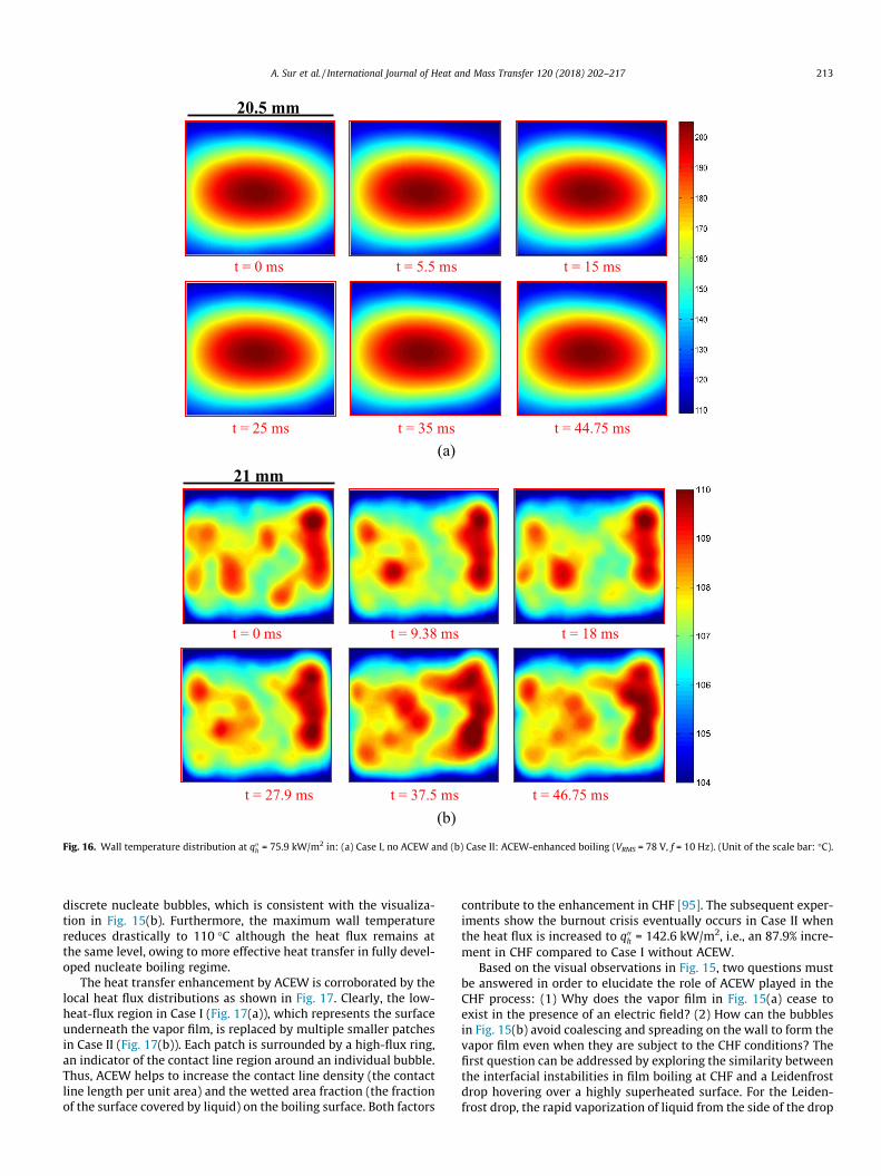
Fig. 16. Wall temperature distribution at q00h = 75.9 kW/m2 in: (a) Case I, no ACEW and (b) Case II: ACEW-enhanced boiling (VRMS = 78 V, f = 10 Hz). (Unit of the scale bar: �C).
A. Sur et al. / International Journal of Heat and Mass Transfer 120 (2018) 202–217 213
discrete nucleate bubbles, which is consistent with the visualiza-tion in Fig. 15(b). Furthermore, the maximum wall temperaturereduces drastically to 110 �C although the heat flux remains atthe same level, owing to more effective heat transfer in fully devel-oped nucleate boiling regime.
The heat transfer enhancement by ACEW is corroborated by thelocal heat flux distributions as shown in Fig. 17. Clearly, the low-heat-flux region in Case I (Fig. 17(a)), which represents the surfaceunderneath the vapor film, is replaced by multiple smaller patchesin Case II (Fig. 17(b)). Each patch is surrounded by a high-flux ring,an indicator of the contact line region around an individual bubble.Thus, ACEW helps to increase the contact line density (the contactline length per unit area) and the wetted area fraction (the fractionof the surface covered by liquid) on the boiling surface. Both factors
contribute to the enhancement in CHF [95]. The subsequent exper-iments show the burnout crisis eventually occurs in Case II whenthe heat flux is increased to q00
h = 142.6 kW/m2, i.e., an 87.9% incre-ment in CHF compared to Case I without ACEW.
Based on the visual observations in Fig. 15, two questions mustbe answered in order to elucidate the role of ACEW played in theCHF process: (1) Why does the vapor film in Fig. 15(a) cease toexist in the presence of an electric field? (2) How can the bubblesin Fig. 15(b) avoid coalescing and spreading on the wall to form thevapor film even when they are subject to the CHF conditions? Thefirst question can be addressed by exploring the similarity betweenthe interfacial instabilities in film boiling at CHF and a Leidenfrostdrop hovering over a highly superheated surface. For the Leiden-frost drop, the rapid vaporization of liquid from the side of the drop

(a)
(b)
t = 0 ms t = 5.5 ms t = 15 ms
t = 25 ms t = 35 ms t = 44.75 ms
20.5 mm 5x 10⁵
4.5
4
3.5
3
2.5
5
t = 0 ms t = 9.38 ms t = 18 ms
t = 27.9 ms t = 37.5 ms t = 46.75 ms
21 mm x 105
4.5
4
3.5
3
2.5
Fig. 17. Local wall heat flux distribution at q00h = 75.9 kW/m2 in: (a) Case I, no ACEWand (b) Case II: ACEW-enhanced boiling (VRMS = 78 V, f = 10 Hz). (Unit of the scale bar:W/m2).
3 A DC field works much less effectively due to the lack of the dynamicestabilizing effect.
214 A. Sur et al. / International Journal of Heat and Mass Transfer 120 (2018) 202–217
facing the surface produces a vapor layer that levitates the dropabove the surface. If an electric field is applied between the dropand the solid substrate, a concentrated interfacial electric field willbe induced across the vapor layer, leading to an electrostaticattraction force that disrupts the liquid-vapor interface and pullsthe drop downward to rewet the surface, i.e., the Leidenfrost stateis suppressed [101,102]. In this study, the applied electric field isconfined predominantly in the SiO2 layer of the silicon wafer foran intimate liquid-solid contact or when the bubble size is large.However, when CHF occurs, the electric field will be biased towardthe thin vapor film, due to its comparable electrical capacitance tothe SiO2 layer. When an AC field is actuated, it stimulates an oscil-latory Maxwell stress force at the liquid-vapor interface, which willpromote the hydrodynamic instability and cause the vapor film to
collapse prematurely3. This effect will persist till the wall superheatincreases to such an extent that the vapor film will grow explosivelyto a thickness much larger that the SiO2 layer immediately upon theliquid-solid contact, which sets the limit for ACEW-enhancement ofCHF. The second question, the longevity of individual bubbles at CHF,can be understood by inspecting the force balance on a growing bub-ble. According to [103–105], CHF occurs when the vapor recoil force(i.e., a force resulting from the change of fluid momentum as thevapor phase leaves the liquid-vapor interface due to evaporation)overcomes the sum of the surface tension and gravitational forces
d
(a)
(b)
0 10 20 30 40 50 60 70 800
20
40
60
80
100
120
140
160
Hydrophobic surfaceEW-modulated (V r.m.s = 78 V, f = 10 Hz)
Wal
l hea
t flu
x (k
W/m
2 )
Wall superheat (°C)
Hydrophobic surfaceACEW-enhanced surface (VRMS = 78 V, f = 10 Hz)
0 20 40 60 80 100 120 140 160 180 2000
1
2
3
4
5
6
7
8
9
10
Boili
ng h
eat t
rans
fer c
oeff
icie
nt (k
W/m
2 -K)
Wall heat flux (kW/m2)
Hydrophobic surfaceEW-modulated (V
r.m.s= 78 V, f = 10 Hz)
Hydrophobic surfaceACEW-enhanced surface (VRMS = 78 V, f = 10 Hz)
Fig. 18. Comparison of pool boiling heat transfer performance: (a) boiling curve and(b) boiling heat transfer coefficient.
A. Sur et al. / International Journal of Heat and Mass Transfer 120 (2018) 202–217 215
that hold the bubble on the boiling surface. When ACEW is applied, itcan be shown that the electrical force acts against the recoil forceand is able to impede the spreading of the contact line on the boilingsurface, thus delaying the occurrence of CHF [106].
4.4. Overall boiling heat transfer performance
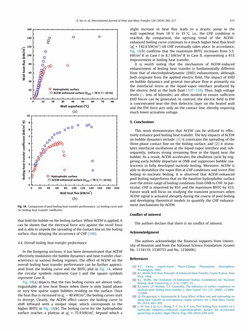
In the foregoing sections, it has been demonstrated that ACEWeffectively modulates the bubble dynamics and heat transfer char-acteristics in various boiling regimes. The effect of ACEW on theoverall boiling heat transfer performance can be further appreci-ated from the boiling curve and the BHTC plot in Fig. 18, wherethe circular symbols represent Case I and the square symbolsrepresent Case II.
Fig. 18(a) depicts that the two boiling curves are almost indis-tinguishable at low heat fluxes when there is only liquid phaseor very few sparse vapor bubbles residing on the surface. Oncethe heat flux is increased to q00
h � 40 kW/m2, the boiling curves startto diverge. Clearly, the ACEW effect causes the boiling curve toshift leftward with a steeper slope, which corresponds to thehigher BHTC in Fig. 18(b). The boiling curve for the hydrophobicsurface reaches a plateau at q00
h = 75.9 kW/m2, beyond which a
slight increase in heat flux leads to a drastic jump in thewall superheat from 18 �C to 35 �C, i.e., the CHF condition isreached. By comparison, the uprising trend of the ACEW-enhanced boiling curve continues to a much higher heat flux level(q00
h = 142.6 kW/m2) till CHF eventually takes place. In accordance,Fig. 18(b) confirms that the maximum BHTC increases from 5.5kW/m2 K in Case I to 8.7 kW/m2 K in Case II, representing a 41%improvement in boiling heat transfer.
It is worth noting that the mechanism of ACEW-inducedenhancement of boiling heat transfer is fundamentally differentfrom that of electrohydrodynamic (EHD) enhancement, althoughboth originate from the applied electric field. The impact of EHDon bubble dynamics and general two-phase flow is primarily viathe interfacial stress at the liquid-vapor interface produced bythe electric field in the bulk fluid [107–110]. Thus, high voltagelevels (� tens of kilovolts) are often needed to ensure sufficientEHD forces can be generated. In contrast, the electric field in EWis concentrated near the thin dielectric layer on the heated walland the EW force acts only on the contact line, thereby requiringmuch lower actuation voltage.
5. Conclusions
This work demonstrates that ACEW can be utilized to effec-tively enhance pool boiling heat transfer. The key impacts of ACEWon bubble dynamics include: (1) it constrains the spreading of thethree-phase contact line on the boiling surface, and (2) it stimu-lates interfacial oscillations at the liquid-vapor interface and, sub-sequently, induces strong streaming flow in the liquid near thebubble. As a result, ACEW accelerates the ebullition cycle by trig-gering early bubble departure at ONB and suppresses bubble coa-lescence in fully developed nucleate boiling. Moreover, ACEW isable to destabilize the vapor film at CHF conditions and revert filmboiling to nucleate boiling. It is observed that ACEW-enhancedpool boiling outperforms that on the baseline hydrophobic surfaceover the entire range of boiling conditions from ONB to CHF. In par-ticular, CHF is improved by 85% and the maximum BHTC by 41%.Future work will focus on studying the transient processes whenACEW signal is actuated abruptly during the course of pool boilingand developing theoretical models to quantify the CHF enhance-ment mechanisms by ACEW.
Conflict of interest
The authors declare that there is no conflict of interest.
Acknowledgment
The authors acknowledge the financial supports from Univer-sity of Houston and from the National Science Foundation (GrantsNo. 1134119, 1530753 and No. 1236606).
References
[1] V.P. Carey, Liquid-Vapor Phase-Change Phenomena, Hemisphere,Washington, 1992.
[2] R.L. Webb, N.H. Kim, Principle of Enhanced Heat Transfer, Taylor Francis, NewYork, 1994.
[3] R.L. Webb, The Evolution of Enhanced Surface Geometries for NucleateBoiling, Heat Transf. Eng. 2 (3–4) (1981) 23.
[4] B.J. Jones, J.P. McHale, S.V. Garimella, The influence of surface roughness onnucleate pool boiling heat transfer, J. Heat Transf. 131 (12) (2009), 121009-121009.
[5] S.J. Thiagarajan, S. Narumanchi, R. Yang, Effect of flow rate and subcooling onspray heat transfer on microporous copper surfaces, Int. J. Heat Mass Transf.69 (2014) 493–505.
[6] L.-W. Fan, J.-Q. Li, L. Zhang, Z.-T. Yu, K.-F. Cen, Pool boiling heat transfer on ananoscale roughness-enhanced superhydrophilic surface for acceleratedquenching in water, Appl. Therm. Eng. 109 (2016) 630–639.

216 A. Sur et al. / International Journal of Heat and Mass Transfer 120 (2018) 202–217
[7] H.H. Son, G.H. Seo, U. Jeong, S.J. Kim, Capillary wicking effect of a Cr-sputteredsuperhydrophilic surface on enhancement of pool boiling critical heat flux,Int. J. Heat Mass Transf. 113 (2017) 115–128.
[8] S.M. You, J.H. Kim, K.H. Kim, Effect of nanoparticles on critical heat flux ofwater in pool boiling heat transfer, Appl. Phys. Lett. 83 (16) (2003) 3374–3376.
[9] D.H. Min, G.S. Hwang, Y. Usta, O.N. Cora, M. Koc, M. Kaviany, 2-D and 3-Dmodulated porous coatings for enhanced pool boiling, Int. J. Heat Mass Transf.52 (11–12) (2009) 2607–2613.
[10] E. Forrest, E. Williamson, J. Buongiorno, L.-W. Hu, M. Rubner, R. Cohen,Augmentation of nucleate boiling heat transfer and critical heat flux usingnanoparticle thin-filmcoatings, Int. J. HeatMass Transf. 53 (1–3) (2010) 58–67.
[11] H. Seo, J.H. Chu, S.-Y. Kwon, I.C. Bang, Pool boiling CHF of reduced grapheneoxide, graphene, and SiC-coated surfaces under highly wettable FC-72, Int. J.Heat Mass Transf. 82 (2015) 490–502.
[12] R. Bertossi, N. Caney, J.A. Gruss, O. Poncelet, Pool boiling enhancement usingswitchable polymers coating, Appl. Therm. Eng. 77 (2015) 121–126.
[13] S. Sarangi, J.A. Weibel, S.V. Garimella, Effect of particle size on surface-coatingenhancement of pool boiling heat transfer, Int. J. Heat Mass Transf. 81 (2015)103–113.
[14] S. Das, D.S. Kumar, S. Bhaumik, Experimental study of nucleate pool boilingheat transfer of water on silicon oxide nanoparticle coated copper heatingsurface, Appl. Therm. Eng. 96 (2016) 555–567.
[15] M.M. Sarafraz, F. Hormozi, Experimental investigation on the pool boilingheat transfer to aqueous multi-walled carbon nanotube nanofluids on themicro-finned surfaces, Int. J. Therm. Sci. 100 (2016) 255–266.
[16] A. Jaikumar, S.G. Kandlikar, Ultra-high pool boiling performance and effect ofchannel width with selectively coated open microchannels, Int. J. Heat MassTransf. 95 (2016) 795–805.
[17] M. Karimzadehkhouei, M. Shojaeian, K. S�endur, M.P. Mengüç, A. Kos�ar, Theeffect of nanoparticle type and nanoparticle mass fraction on heat transferenhancement in pool boiling, Int. J. Heat Mass Transf. 109 (2017) 157–166.
[18] A. Jaikumar, S.G. Kandlikar, A. Gupta, Pool Boiling Enhancement throughGraphene and Graphene Oxide Coatings, Heat Transf. Eng. 38 (14–15) (2017)1274–1284.
[19] A. Khalili Sadaghiani, A.R. Motezakker, A.V. Özpınar, G. Özaydın _Ince, A. Kos�ar,Pool boiling heat transfer characteristics of inclined pHEMA-coated surfaces,J. Heat Transf. 139 (11) (2017).
[20] S. Launay, A.G. Fedorov, Y. Joshi, A. Cao, P.M. Ajayan, Hybrid micro-nanostructured thermal interfaces for pool boiling heat transfer enhancement,Microelectron. J. 37 (11) (2006) 1158–1164.
[21] S. Li, R. Furberg, M.S. Toprak, B. Palm, M. Muhammed, Nature-Inspired BoilingEnhancement by Novel Nanostructured Macroporous Surfaces, Adv. Funct.Mater. 18 (15) (2008) 2215–2220.
[22] C.H. Li, T. Li, P. Hodgins, C.N. Hunter, A.A. Voevodin, J.G. Jones, G.P. Peterson,Comparison study of liquid replenishing impacts on critical heat flux and heattransfer coefficient of nucleate pool boiling on multiscale modulated porousstructures, Int. J. Heat Mass Transf. 54 (15–16) (2011) 3146–3155.
[23] J.A. Weibel, S.S. Kim, T.S. Fisher, S.V. Garimella, Carbon nanotube coatings forenhanced capillary-fed boiling from porous microstructures, NanoscaleMicroscale Thermophys. Eng. 16 (1) (2012) 1–17.
[24] J.Y. Ho, K.C. Leong, C. Yang, Saturated pool boiling from carbon nanotubecoated surfaces at different orientations, Int. J. Heat Mass Transf. 79 (2014)893–904.
[25] C.M. Patil, S.G. Kandlikar, Pool boiling enhancement through microporouscoatings selectively electrodeposited on fin tops of open microchannels, Int. J.Heat Mass Transf. 79 (2014) 816–828.
[26] D.E. Kim, D.I. Yu, D.W. Jerng, M.H. Kim, H.S. Ahn, Review of boiling heattransfer enhancement on micro/nanostructured surfaces, Exp. Therm FluidSci. 66 (2015) 173–196.
[27] M. Ray, S. Deb, S. Bhaumik, Pool boiling heat transfer of refrigerant R-134a onTiO 2 nano wire arrays surface, Appl. Therm. Eng. 107 (2016) 1294–1303.
[28] Y. Tang, J. Zeng, S. Zhang, C. Chen, J. Chen, Effect of structural parameters onpool boiling heat transfer for porous interconnected microchannel nets, Int. J.Heat Mass Transf. 93 (2016) 906–917.
[29] S. Das, B. Saha, S. Bhaumik, Experimental study of nucleate pool boiling heattransfer of water by surface functionalization with crystalline TiO2nanostructure, Appl. Therm. Eng. 113 (2017) 1345–1357.
[30] M. Zupancic, M. Moze, P. Gregorcic, I. Golobic, Nanosecond laser texturing ofuniformly and non-uniformly wettable micro structured metal surfaces forenhanced boiling heat transfer, Appl. Surf. Sci. 399 (2017) 480–490.
[31] P.A. Raghupathi, S.G. Kandlikar, Pool boiling enhancement through contactline augmentation, Appl. Phys. Lett. 110 (20) (2017) 204101.
[32] H.S. Jo, S. An, H.G. Park, M.-W. Kim, S.S. Al-Deyab, S.C. James, J. Choi, S.S. Yoon,Enhancement of critical heat flux and superheat through controlledwettability of cuprous-oxide fractal-like nanotextured surfaces in poolboiling, Int. J. Heat Mass Transf. 107 (2017) 105–111.
[33] H.J. Cho, D.J. Preston, Y. Zhu, E.N. Wang, Nanoengineered materials for liquid–vapour phase-change heat transfer, Nat. Rev. Mater. 2 (2016) 16092.
[34] H.T. Phan, N. Caney, P. Marty, S. Colasson, J. Gavillet, Surface wettabilitycontrol by nanocoating: The effects on pool boiling heat transfer andnucleation mechanism, Int. J. Heat Mass Transf. 52 (23–24) (2009) 5459–5471.
[35] H. Jo, M. Kaviany, S.H. Kim, M.H. Kim, Heterogeneous bubble nucleation onideally-smooth horizontal heated surface, Int. J. Heat Mass Transf. 71 (2014)149–157.
[36] B. Bourdon, E. Bertrand, P. Di Marco, M. Marengo, R. Rioboo, J. De Coninck,Wettability influence on the onset temperature of pool boiling: Experimentalevidence onto ultra-smooth surfaces, Adv. Colloid Interface Sci. 221 (2015)34–40.
[37] F. Villa, A. Georgoulas, M. Marengo, P. Di Marco, J. De Coninck, Pool boilingversus surface wettability characteristics, 2016.
[38] J. Kim, S. Jun, J. Lee, S.H. Lee, S.M. You, Effect of wettability on pool boilingincipience in saturated water, J. Heat Transf. 138 (8) (2016) 080910.
[39] T. Harada, H. Nagakura, T. Okawa, Dependence of bubble behavior insubcooled boiling on surface wettability, Nucl. Eng. Des. 240 (12) (2010)3949–3955.
[40] Y. Nam, E. Aktinol, V.K. Dhir, Y.S. Ju, Single bubble dynamics on asuperhydrophilic surface with artificial nucleation sites, Int. J. Heat MassTransf. 54 (7–8) (2011) 1572–1577.
[41] X. Chen, H. Qiu, Bubble dynamics and heat transfer on a wettability patternedsurface, Int. J. Heat Mass Transf. 88 (2015) 544–551.
[42] M.T. Taylor, T. Qian, Thermal singularity and contact line motion in poolboiling: Effects of substrate wettability, Phys. Rev. E 93 (3) (2016) 033105.
[43] C. Marcel, A. Clausse, C. Frankiewicz, A. Betz, D. Attinger, Numericalinvestigation into the effect of surface wettability in pool boiling heattransfer with a stochastic-automata model, Int. J. Heat Mass Transf. 111(2017) 657–665.
[44] E. Teodori, T. Valente, I. Malavasi, A.S. Moita, M. Marengo, A.L.N. Moreira,Effect of extreme wetting scenarios on pool boiling conditions, Appl. Therm.Eng. 115 (Supplement C) (2017) 1424–1437.
[45] S.J. Kim, I.C. Bang, J. Buongiorno, L.W. Hu, Surface wettability change duringpool boiling of nanofluids and its effect on critical heat flux, Int. J. Heat MassTransf. 50 (19–20) (2007) 4105–4116.
[46] C.-C. Hsu, P.-H. Chen, Surface wettability effects on critical heat flux of boilingheat transfer using nanoparticle coatings, Int. J. Heat Mass Transf. 55 (13–14)(2012) 3713–3719.
[47] H.T. Phan, R. Bertossi, N. Caney, P. Marty, S. Colasson, A model to predict theeffect of surface wettability on critical heat flux, Int. Commun. Heat MassTransf. 39 (10) (2012) 1500–1504.
[48] S. Mori, S. Mt Aznam, K. Okuyama, Enhancement of the critical heat flux insaturated pool boiling of water by nanoparticle-coating and a honeycombporous plate, Int. J. Heat Mass Transf. 80 (2015) 1–6.
[49] S. Mori, Y. Utaka, Critical heat flux enhancement by surface modification in asaturated pool boiling: A review, Int. J. Heat Mass Transf. 108 (2017) 2534–2557.
[50] N. Nagai, V.P. Carey, Assessment of surface wettability and its relation toboiling phenomena, Therm. Sci. Eng. 10 (3) (2002) 1–9.
[51] C.-H. Choi, M. David, Z. Gao, A. Chang, M. Allen, H. Wang, C.-H. Chang, Large-scale generation of patterned bubble arrays on printed bi-functional boilingsurfaces, Sci. Rep. 6 (2016) 23760.
[52] Y. Takata, Hidaka, S. Kohno, M, Enhanced nucleate boiling bysuperhydrophobic coating with checkered and spotted patterns, in:International Conference on Boiling Heat Transfer, Spoleto, 2006.
[53] A.R. Betz, J. Xu, H.H. Qiu, D. Attinger, Do surfaces with mixed hydrophilic andhydrophobic areas enhance pool boiling?, Appl Phys. Lett. 97 (14) (2010).
[54] H. Jo, H.S. Ahn, S. Kang, M.H. Kim, A study of nucleate boiling heat transfer onhydrophilic, hydrophobic and heterogeneous wetting surfaces, Int. J. HeatMass Transf. 54 (25–26) (2011) 5643–5652.
[55] A.R. Betz, J. Jenkins, C.J. Kim, D. Attinger, Boiling heat transfer onsuperhydrophilic, superhydrophobic, and superbiphilic surfaces, Int. J. HeatMass Transf. 57 (2) (2013) 733–741.
[56] H. Jo, S. Kim, H.S. Park, M.H. Kim, Critical heat flux and nucleate boiling onseveral heterogeneous wetting surfaces: controlled hydrophobic patterns ona hydrophilic substrate, Int. J. Multiph. Flow 62 (2014) 101–109.
[57] H. Jo, D.I. Yu, H. Noh, H.S. Park, M.H. Kim, Boiling on spatially controlledheterogeneous surfaces: wettability patterns on microstructures, Appl. Phys.Lett. 106 (18) (2015).
[58] A. Fazeli, M. Mortazavi, S. Moghaddam, Hierarchical biphilicmicro/nanostructures for a new generation phase-change heat sink, Appl.Therm. Eng. 78 (2015) 380–386.
[59] M. Zupancic, M. Steinbücher, P. Gregorcic, I. Golobic, Enhanced pool-boilingheat transfer on laser-made hydrophobic/superhydrophilic polydimethyl-siloxane-silica patterned surfaces, Appl. Therm. Eng. 91 (2015) 288–297.
[60] R. Holguin, K. Kota, S. Wootton, R.-H. Chen, S. Ross, Enhanced boiling heattransfer on binary surfaces, Int. J. Heat Mass Transf. 114 (2017) 1105–1113.
[61] X. Dai, X. Huang, F. Yang, X. Li, J. Sightler, Y. Yang, C. Li, Enhanced nucleateboiling on horizontal hydrophobic-hydrophilic carbon nanotube coatings,Appl. Phys. Lett. 102 (16) (2013) 161605.
[62] A.S. Kousalya, K.P. Singh, T.S. Fisher, Heterogeneous wetting surfaces withgraphitic petal-decorated carbon nanotubes for enhanced flow boiling, Int. J.Heat Mass Transf. 87 (2015) 380–389.
[63] H. Jo, D.I. Yu, H. Noh, H.S. Park, M.H. Kim, Boiling on spatially controlledheterogeneous surfaces: Wettability patterns on microstructures, Appl. Phys.Lett. 106 (18) (2015) 181602.
[64] C.S.S. Kumar, Y.W. Chang, P.-H. Chen, Effect of heterogeneous wettablestructures on pool boiling performance of cylindrical copper surfaces, Appl.Therm. Eng. (2017).
[65] R. Wen, Q. Li, W. Wang, B. Latour, C.H. Li, C. Li, Y.-C. Lee, R. Yang, Enhancedbubble nucleation and liquid rewetting for highly efficient boiling heattransfer on two-level hierarchical surfaces with patterned copper nanowirearrays, Nano Energy (2017).

A. Sur et al. / International Journal of Heat and Mass Transfer 120 (2018) 202–217 217
[66] Y. Takata, S. Hidaka, J.M. Cao, T. Nakamura, H. Yamamoto, M. Masuda, T. Ito,Effect of surface wettability on boiling and evaporation, Energy 30 (2–4)(2005) 209–220.
[67] B.J. Zhang, R. Ganguly, K.J. Kim, C.Y. Lee, Control of pool boiling heat transferthrough photo-induced wettability change of titania nanotube arrayedsurface, Int. Commun. Heat Mass Transfer 81 (2017) 124–130.
[68] A.S. Kousalya, C.N. Hunter, S.A. Putnam, T. Miller, T.S. Fisher, Photonicallyenhanced flow boiling in a channel coated with carbon nanotubes, Appl. Phys.Lett. 100 (7) (2012) 071601.
[69] C.N. Hunter, D.B. Turner, M.L. Jespersen, M.H. Check, P.T. Borton, N.R. Glavin,A.A. Voevodin, Fast photo-switchable surfaces for boiling heat transferapplications, Appl. Phys. Lett. 101 (19) (2012) 191603.
[70] H.J. Cho, J.P. Mizerak, E.N. Wang, Turning bubbles on and off during boilingusing charged surfactants, Nat. Commun. 6 (2015) 8599.
[71] S.H. Ko, S.J. Lee, K.H. Kang, A synthetic jet produced by electrowetting-drivenbubble oscillations in aqueous solution, Appl. Phys. Lett. 94 (19) (2009)194102.
[72] T.D. Blake, A. Clarke, E.H. Stattersfield, An investigation of electrostatic assistin dynamic wetting, Langmuir 16 (6) (2000) 2928–2935.
[73] J. Lahann, S. Mitragotri, T.-N. Tran, H. Kaido, J. Sundaram, I.S. Choi, S. Hoffer, G.A. Somorjai, R. Langer, A reversibly switching surface, Science 299 (5605)(2003) 371–374.
[74] N. Verplanck, Y. Coffinier, V. Thomy, R. Boukherroub, Wettability switchingtechniques on superhydrophobic surfaces, Nanoscale Res Lett 2 (12) (2007)577–596.
[75] N. Mori, H. Horikawa, H. Furukawa, T. Watanabe, Temperature-inducedchanges in the surface wettability of SBR + PNIPA Films, Macromol. Mater.Eng. 292 (8) (2007) 917–922.
[76] D. Wang, X. Wang, X. Liu, F. Zhou, Engineering a titanium surface withcontrollable oleophobicity and switchable oil adhesion, The J. Phys. Chem. C114 (21) (2010) 9938–9944.
[77] F. Mugele, J.C. Baret, Electrowetting: From basics to applications, J. Phys.-Condens. Mat. 17 (28) (2005) R705–R774.
[78] J. Atencia, D.J. Beebe, Controlled microfluidic interfaces, Nature 437 (7059)(2005) 648–655.
[79] H.L. Bralower, A study of electrowetting-assisted boiling, 2011.[80] J. Hong, S. Ko, K. Kang, I. Kang, A numerical investigation on AC electrowetting
of a droplet, Microfluid. Nanofluid. 5 (2) (2008) 263–271.[81] L. Chen, E. Bonaccurso, Electrowetting – From statics to dynamics, Adv.
Colloid Interface Sci. 210 (2014) 2–12.[82] J.M. Oh, S.H. Ko, K.H. Kang, Shape oscillation of a drop in ac electrowetting,
Langmuir 24 (15) (2008) 8379–8386.[83] Y. Lu, A. Sur, C. Pascente, S.R. Annapragada, P. Ruthhoeft, D. Liu, Dynamics of
droplet motion induced by electrowetting, Int. J. Heat Mass Transf. 106(2017) 920–931.
[84] S. Chung, K. Rhee, S. Cho, Bubble actuation by electrowetting-on-dielectric(EWOD) and its applications: a review, Int. J. Precis. Eng. Manuf. 11 (6) (2010)991–1006.
[85] A. Sur, An experimental investigation of electrowetting modulated nucleateboiling, University of Houston, Houston, TX, 2014.
[86] C. Gerardi, J. Buongiorno, L.-W. Hu, T. McKrell, Study of bubble growth inwater pool boiling through synchronized, infrared thermometry and high-speed video, Int. J. Heat Mass Transf. 53 (19–20) (2010) 4185–4192.
[87] W. Kaiser, H.Y. Fan, Infrared absorption of indium antimonide, Phys. Rev. 98(4) (1955) 966–968.
[88] T.S. Moss, T.D.H. Hawkins, The infra-red emissivities of indium antimonideand germanium, Proc. Phys. Soc. Lond. 72 (464) (1958) 270–273.
[89] C.J. Gerritsm, J.H. Haanstra, Infrared transmission of air under laboratoryconditions, Infrared Phys. 10 (2) (1970) 79–90.
[90] M.H.N. Naraghi, V.W. Antonetti, Macro-constriction resistance of distributedcontact contour areas in a vacuum environment, in: A. HTD (Ed.) ASMEWinter Annual Meeting, 1993, pp. 107–114.
[91] S. Lee, S. Song, V. Au, K.P. Moran, Constriction/spreading resistance model forelectronics packaging, in: ASME (Ed.) ASME/JSME Thermal EngineeringConference, 1995.
[92] E. Wagner, P. Stephan, High-resolution measurements at nucleate boiling ofpure FC-84 and FC-3284 and its binary mixtures, J. Heat Trans.-T Asme. 131(12) (2009).
[93] Y. Heng, A. Mhamdi, E. Wagner, P. Stephan, W. Marquardt, Estimation of localnucleate boiling heat flux using a three-dimensional transient heatconduction model, Inverse. Probl. Sci. Eng. 18 (2) (2010) 279–294.
[94] S. Jung, H. Kim, Synchronized measurement of liquid-vapor phase andtemperature distributions on a boiling surface during single bubble nucleateboiling, in: 8th International Conference on Multiphase Flow, Jeju, Korea,2013.
[95] J. Jung, S.J. Kim, J. Kim, Observations of the critical heat flux process duringpool boiling of FC-72, J. Heat Transf. 136 (4) (2014), 041501-041501.
[96] C.D. Gerardi, Investigation of pool boiling heat transfer enhancement of nanoengineered fluids by means of high-speed infrared thermography,Massachusetts Institute of Technology, Boston, 2009, Dissertation.
[97] S.J. Kline, I.A. McClintok, Describing uncertainties in single-sampleexperiments, Mech. Eng. (January) (1953) 3–8.
[98] H.T. Phan N. Caney P. Marty S. Colasson J. Gavillet A. Marechal, Influence ofsurface wettability on pool boiling heat transfer, in: ICNMM 2009 Pts a-B,2009 pp. 17–23.
[99] H.T. Phan, N. Caney, P. Marty, S. Colasson, J. Gavillet, Effects of surfacewettability on heterogeneous boiling, Proceedings of ASME 2009 SecondInternational Conference on Micro/Nanoscale Heat and Mass Transfer,Volume 2 Shanghai, China, December 18–21, 2009, 2, 2009, pp. 91–96.
[100] L. Yi, J.M. Bao, D. Liu, Dynamics of a leidenfrost droplet modulated byelectrowetting, J. Heat Transf., Rev. (2017).
[101] F. Celestini, G. Kirstetter, Effect of an electric field on a Leidenfrost droplet,Soft Matter 8 (22) (2012) 5992–5995.
[102] A. Shahriari, J. Wurz, V. Bahadur, Heat transfer enhancement accompanyingleidenfrost state suppression at ultrahigh temperatures, Langmuir 30 (40)(2014) 12074–12081.
[103] K. Sefiane, D. Benielli, A. Steinchen, A new mechanism for pool boiling crisis,recoil instability and contact angle influence, Colloids Surf., A 142 (2–3)(1998) 361–373.
[104] V.S. Nikolayev, D.A. Beysens, Boiling crisis and non-equilibrium dryingtransition, EPL (Europhys. Lett.) 47 (3) (1999) 345.
[105] S.G. Kandlikar, A theoretical model to predict pool boiling chf incorporatingeffects of contact angle and orientation, J. Heat Transf. 123 (6) (2001) 1071–1079.
[106] A. Sur, Y. Lu, P. Carmen, P. Ruthhoeft, J.M. Bao, D. Liu, Enhancing critical heatflux with electrowetting, in preparation, 2017.
[107] J. Seyed-Yagoobi, J.E. Bryan, Enhancement of heat transfer and mass transportin single-phase and two-phase flows with electrohydrodynamics, Adv. HeatTransf. 33 (1999) 95–186.
[108] J.E. Bryan, J. Seyed-Yagoobi, Influence of flow regime, heat flux, and mass fluxon electrohydrodynamically enhanced convective boiling, J. Heat Transf. 123(2) (2001) 355–367.
[109] V.K. Patel, J. Seyed-Yagoobi, Combined dielectrophoretic andelectrohydrodynamic conduction pumping for enhancement of liquid filmflow boiling, J. Heat Transf. 139 (6) (2017) 061502.
[110] V. Pandey, G. Biswas, A. Dalal, Saturated film boiling at various gravity levelsunder the influence of electrohydrodynamic forces, Phys. Fluids 29 (3) (2017)032104.