internal gear pumps installation manual
TRANSCRIPT

333
E 2
.905
.M.0
/02.
14
5
Internal Gear PumpsInstallation Manual
MEDIUM HEAVY DUTY SERIES SIZE 2 PGI100PGI100-2-005
PGI100-2-006
PGI100-2-008
PGI100-2-011
PGI100-2-013
PGI100-2-016
PGI100-2-019
PGI100-2-022
PGI100-2-025
MEDIUM HEAVY DUTY SERIES SIZE 3/6 PGI101PGI101-3-020 PGI101-6-125
PGI101-3-025 PGI101-6-160
PGI101-3-032 PGI101-6-200
PGI101-3-040 PGI101-6-250
PGI101-3-050
PGI101-3-064
HEAVY DUTY SERIES SIZE 2/3/6 PGI102PGI102-2-004 PGI102-3-014 PGI102-6-040
PGI102-2-005 PGI102-3-016 PGI102-6-050
PGI102-2-006 PGI102-3-020 PGI102-6-064
PGI102-2-008 PGI102-3-025 PGI102-6-080
PGI102-2-011 PGI102-3-032 PGI102-6-100
PGI102-2-013 PGI102-3-040 PGI102-6-125
PGI102-2-016 PGI102-3-050 PGI102-6-160
PGI102-2-019 PGI102-3-064 PGI102-6-200
PGI102-2-022 PGI102-6-250
PGI102-2-025
MEDIUM HEAVY DUTY SERIES SIZE 5/6 PGI103PGI103-5-064 PGI103-6-125
PGI103-5-080 PGI103-6-160
PGI103-5-100 PGI103-6-200
PGI103-6-250

334
E 2
.905
.M.0
/02.
14To prevent serious accidents, equipment damage, and other property damage, please observe the following precautions, as well as all related regulations regarding safety.
Before using the product, make sure you read and understand all the instructions in the Operator‘s Manual entirely.
In this catalogue, safety precautions are classified under three headings: DANGER, WARNING, and CAUTION. These words are defined as follows:
DANGERIndicates an imminent danger that is very likely to cause death or severe injury unless the situation is avoided.
WARNINGIndicates a potential danger that may cause death or severe injury unless the situation is avoided.
CAUTIONIndicates a potential danger that may cause a minor or moderate injury or that may result in property damage.
INFORMATIONIndicates useful hints and system tips. They are necessary for correct installation and safe use of the product.
PRECAUTIONS FOR USE
CAUTION1. To avoid possible injury when handling the products, wear protective safety equipment in accordance with the instructions in the Operator’s Manual.
CAUTION2. Failure to support the weight of the product or lifting the product with incorrect posture may result in injury to the hands or back. Be sure to follow the instructions in the Operator's Manual.
CAUTION3. Do not climb on, strike, drop or exert unnecessary force on the product. This may lead to injury or fire due to incorrect operation, damage, or oil leakage.
CAUTION4. Oil on the product or floor must be cleaned up thoroughly. Oil could cause you to drop the product or slip on the floor.
PRECAUTIONS FOR INSTALLATION, REMOVAL, AND MAINTENANCEWARNING1. All installation, removal, maintenance, piping or wiring work should be carried out by properly trained personnel.
WARNING2. Before beginning any installation, removal, maintenance, piping or wiring work, the following procedures must be carried out. Failure to do so may cause the equipment to move suddenly or oil to spill during the work, which may result in serious accidents.
zShut off the power supply to the equipment and make sure that all the electrical motors or machines cannot re-start unintentionally. zSecure the cylinder rods before installing/removing the cylinder. zReduce the pressure in the pipes and cylinders in the hydraulic system to zero pressure.
WARNING3. Before working on any electrical wiring, be sure to shut off the power supply. Failure to do this may cause an electric shock.
CAUTION4. Keep all installation holes and surfaces clean. Failure to do this may cause insufficient tightening of the bolts which may lead to a fire due to oil leakage.
CAUTION5. Before commissioning the device, make sure that all bolts are tightened with the specified torque. Failure to comply with the specifications may cause incorrect operation, damage, oil leakage, etc.

335
E 2
.905
.M.0
/02.
14
5
PRECAUTIONS FOR OPERATION
DANGER1. Never operate any device in an environment where there is danger of explosion or fire, unless the device is fully protected. This may lead to major and serious accidents including explosion or fire.
WARNING2. Do not approach the pumps or motors when in operation. Hands or clothes can be caught up and wound into the pumps and motors which can lead to serious injury.
WARNING3. In event of abnormal operation (unusual sounds, oil leakage, smoke, etc.), immediately stop operation and take appropriate corrective measures.
WARNING4. Completely discharge air from the cylinder at low pressure. Failure to do so may result in unexpected movement of the cylinder, which in turn may cause injury.
WARNING5. To adjust the damping, gradually increase the cylinder speed from a low speed (50 mm/s or less). Rapidly accelerating the cylinder may produce an abnormal pressure surge, resulting in damage to the cylinder or the machinery and causing a serious accident.
WARNING6. Before operating this device for the first time, check that hydraulic and electrical circuits are properly connected and that adjoining surfaces are tightly aligned.
WARNING7. Do not use the product outside of the specifications described in the catalogue, related data sheets, drawings, etc. Failure to adhere to them may cause incorrect operation, damage or injury.
WARNING8. During operation, high temperatures in the hydraulic system or solenoid valves may occur. Wear protective equipment on hands and body when in the vicinity of these devices.
WARNING9. Always operate the device with clean oil, and within established ranges for temperature, viscosity and cleanliness. Failure to adhere to the specified limits may result in incorrect operation or fire due to oil leakage.
GENERAL PRECAUTIONS
WARNING1. Never modify the device. If any alterations are made, unexpected machine movement may cause injury.
CAUTION2. Do not disassemble the products without prior consent of the manufacturer. Failure to adhere to this can cause the products to operate incorrectly which can lead to accidents or damage.
CAUTION3. For transportation / storage of the product, pay attention to environmental conditions, such as ambient temperature and humidity, and implement anti-dust / anti-corrosion measures.
CAUTION4. The seals may need to be replaced if the product is used after long-term storage.
CAUTION5. Read the manual thoroughly and ensure that the seals are replaced properly.
RELATED REGULATIONS
CAUTIONTo ensure that this product is used in a safe manner, it is essential to observe the above precautions, as well as all related regulations regarding safety.
336
E 2
.905
.M.0
/02.
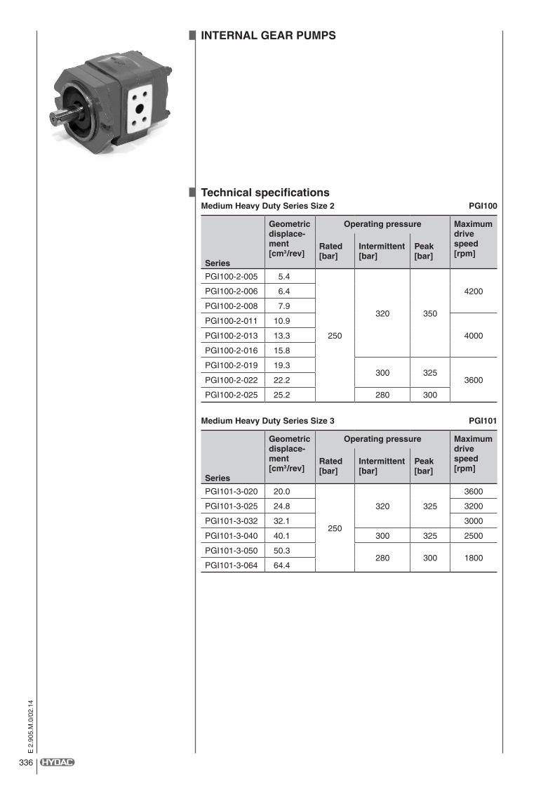
14INTERNAL GEAR PUMPS
Technical specificationsMedium Heavy Duty Series Size 2 PGI100
Series
Geometric displace-ment [cm3/rev]
Operating pressure Maximum drive speed [rpm]
Rated [bar]
Intermittent [bar]
Peak [bar]
PGI100-2-005 5.4
250
320 350
4200PGI100-2-006 6.4
PGI100-2-008 7.9
PGI100-2-011 10.9
4000PGI100-2-013 13.3
PGI100-2-016 15.8
PGI100-2-019 19.3300 325
3600PGI100-2-022 22.2
PGI100-2-025 25.2 280 300
Medium Heavy Duty Series Size 3 PGI101
Series
Geometric displace-ment [cm3/rev]
Operating pressure Maximum drive speed [rpm]
Rated [bar]
Intermittent [bar]
Peak [bar]
PGI101-3-020 20.0
250
320 325
3600
PGI101-3-025 24.8 3200
PGI101-3-032 32.1 3000
PGI101-3-040 40.1 300 325 2500
PGI101-3-050 50.3280 300 1800
PGI101-3-064 64.4

337
E 2
.905
.M.0
/02.
14
5
DocumentationCheck the product's model code and compare it with your paper work.
Delivery note and / or sales acknowledgement.
Heavy Duty Series Size 2/3/6 PGI102
Series
Geometric displace-ment [cm3/rev]
Operating pressure Maximum drive speed [rpm]
Rated [bar]
Intermittent [bar]
Peak [bar]
PGI102-2-004 3.8
330 350 400
4200PGI102-2-005 5.4
PGI102-2-006 6.4
PGI102-2-008 7.9
4000PGI102-2-011 10.9
PGI102-2-013 13.3
PGI102-2-016 15.8
PGI102-2-019 19.3 300300 325
3600PGI102-2-022 22.2250
PGI102-2-025 25.2 280 300
PGI102-3-014 14.6
330 350 400
4000PGI102-3-016 16.0
PGI102-3-020 20.0
PGI102-3-025 24.83000
PGI102-3-032 32.1
PGI102-3-040 40.1
280
300 325 2500
PGI102-3-050 50.3300 325 1800
PGI102-3-064 64.6
PGI102-6-040 40.8330 340 350
2400PGI102-6-050 50.6
PGI102-6-064 65.3 315
330 340PGI102-6-080 80.0300
2200PGI102-6-100 101.2
PGI102-6-125 125.7280 300 320
PGI102-6-160 160.1
2000PGI102-6-200 200.9150 150 165
PGI102-6-250 249.9
Medium Heavy Duty Series Size 5/6 PGI103
Series
Geometric displace-ment [cm3/rev]
Operating pressure Maximum drive speed [rpm]
Rated [bar]
Intermittent [bar]
Peak [bar]
PGI103-5-064 65.3
210 230 2503000
PGI103-5-080 80.4
PGI103-5-100 100.5 2500
PGI103-6-125 125.7250 280 300
2200
PGI103-6-160 160.1 2000
PGI103-6-200 200.9 160 170 1802200
PGI103-6-250 249.9 140 150 160

338
E 2
.905
.M.0
/02.
14INSTALLING THE PUMPInstallation position:The pumps can be installed vertically (shaft at the top) or horizontally.
Note:Internal gear pumps are self-priming. They can be installed both above and below the tank level.
The permitted pressure values on the suction side of the pump must not be exceeded (see Technical Specifications).
Installation instructions:Important!
Prior to installing and commissioning the pump, it must be filled with oil from the suction side.
When installing the pump, ensure that:
• thedirectionofrotationofthedriveandpump,markedbyanarrowonthecaseornameplate,correspondtoeachother.For example, a drive running anti-clockwise requires a pump which runs clockwise.
• thepumpandmotorshaftarealigned.
• compensatingcouplings(flexibledriveorcurved-gearcouplings)areused.
• thepumpisdrivenfreeofaxialandlateralforces.Adriveusinggearwheels,beltsorchainswithoutanadapterbearingis possible only to a limited extent and always requires approval from HYDAC.
• nostressesarecausedtothepumpbyunevenpumpsupport.
• nodistortioniscausedbyincorrectlymountedpipes.
• couplingpartsareinstalledwithoutusingforce.
When installing a HYDAC pump always ensure that the fluid remains in the pump during stoppages.
Sealing faces must not be damaged. Permitted torques for mounting screws at the pump and pipe connections must be adhered to.
When mounting pumps with an O-ring at the drive shaft, make sure the O-ring has been greased and that there is a lead-in chamfer on the mating part to avoid damage to the O-ring.

339
E 2
.905
.M.0
/02.
14
5
OIL RESERVOIR• Theamountofoilrequiredinthereservoirdependsontheparticularoperatingconditions.
It should be at least twice (for intermittent operation and correspondingly long cooling phases) to five times the amount of the pump delivery rate per minute.
• Ifthereservoiristoosmall,coolingoftheoilmayberequired.
• Thereservoirmustbeprovidedwithanairbreatherfilterandastrainerinthefillingport.
• Priortofillingthereservoirwithoil,itmustbethoroughlycleaned.
• Oil-resistantpaintmustbeusedtopaintthereservoir.
• Usebafflestoensuresufficientdistancebetweenthesuctionandreturnlinesand to enable complete deaeration of the oil.
• Recommendedsuctionvelocity 0.5-1.5m/s Maximum return flow velocity 2.0 - 3.0 m/s
OPERATING FLUIDHydraulic mineral oils:Selection• BrandedhydraulicoiltoDIN51524,Part2mustalwaysbeused.
• Blendingseveraltypesofoil,oroilofdifferentmanufacturers,mustbeavoidedbecauseitcanhaveadetrimentaleffecton the hydraulic characteristics of the fluid.
Operating temperature• Theoptimumoperatingtemperatureisfrom40°Cto60°C–ashort-term
maximumtemperaturefrom80°Cto100°Cispermitted.
ViscosityMinimum operating viscosity 10 mm²/s (cSt)
Optimum operating viscosity 25 - 100 mm²/s (cSt)
Maximum starting viscosity 2000 mm²/s (cSt)
When selecting the operating medium’s viscosity, consideration must be given to the average operating temperatures whilst maintaining the permitted viscosity values.
FIRE-RESISTANT FLUIDS AND OTHER FLUIDSPlease contact HYDAC.
Suction line
Min
. 50
mm

340
E 2
.905
.M.0
/02.
14FILTRATIONCareful filtration of the pressure fluid is essential for a long service life and trouble-free operation of the hydraulic system.
Cleanliness level:• Cleanlinessclassoftheoperatingfluid:
Code 20/18/15 to ISO 4406:1999 or NAS 1638 Class 9 or cleaner.
• Inordertoensurealongerservicelifewerecommend to ISO 4406 Code18/16/13 or cleaner or NAS 1638 Class 7 or cleaner.
• Werecommendusingafilterwithaminimumretentionrateofβ 10 > 100.
• Thefilterorfilterelementsmustbemaintainedregularlyandreplaced,ifnecessary.
• Tocheckifthefiltersareoperatingcorrectly,theymustbefittedwithavisual,orpreferablyanelectricalcloggingindicator.
PRESSURE LIMITING• Toavoidexcessivelyhighpressuresinthepump,thepressurereliefvalveshouldbepositionedasclosetothepump
outlet as possible and definitely between the pump and the hydraulic system downstream.
• Selectanappropriatesettingtoensurethatthepump'smaximumpressuresettingwillnot be exceeded (see Technical Specifications).
FUNCTIONAL TEST AND COMMISSIONINGDirection of rotation:Internal gear pumps can be supplied in clockwise and anti-clockwise versions. The pump’s direction of rotation is determined when viewing the drive shaft and is marked by an arrow on the pump case or the name-plate.
Prior to commissioning the pump, check that the direction of rotation of the drive and pump correspond!
Drive speed:The permitted range of drive speeds is given in the brochures.
CAUTION! When operating a combination of pumps, especially when different pump series or sizes are combined, the drive speed must not exceed that permitted for the pump with the lowest speed!
Commissioning:• Itmustbepossibleforthepumptobestartedwithoutload,thatiswithaconsumerthatisunloaded.
• Duringtheinitial commissioning, the pressure line must be vented.
• Ventthesystemuntilallcrackingnoisesandfoaminghavestopped.
At the same time, check the fluid level in the reservoir until the system has been completely vented. Under no circumstances must the oil fall below the minimum level.
• Afterventingthepump,itshouldbeloadedtotherequiredpressure,andthepressurereliefvalveshouldbeprotectedfrom unauthorised adjustment.
• Priortoswitchingoffthepump,thesystemshouldbeunloaded.
• Afteroperatingforsometime,checkthefilterandoiltemperature.