iph catalog, high-pressure internal gear pumps catalog high-pressure internal gear pumps machines...
TRANSCRIPT
IPH CatalogHigh-pressure internal gear pumps
Machines that run
Rarely seen, but hard at work in
countless machines, Voith Turbo
internal gear pumps reliably provide
high pressures. They are mainly
used in the plastic and sheet-metal
processing sectors, presses as well
as conveying and lifting equipment.
The pumps are also in demand for
shipbuilding, municipal vehicles,
power plants and special machine
building.
Benefits that impress
Internal gear pumps from Voith
Turbo are working reliably in hun-
dreds of thousands of machines
around the world. Sophisticated
technology, robust design and cost-
efficient operation have convinced
thousands of customers to trust
Voith. Based on that trust, we have
become the world market leader for
high-pressure internal gear pumps
with gap compensation.
Features that count
Compact dimensions, low operating
noise levels, minimal pressure and
volume pulsation and a high degree
of efficiency have always been
important customer requirements
when it comes to using hydraulic
pumps. IPH high-pressure pumps
with radial and axial sealing gap
compensation have been meeting
these requirements extremely reli-
ably for many years now.
Voith Turbo
Contents
Page
Design and function 3
Performance data 4
IPH 4 6
IPH 5 8
IPH 6 10
SAE suction and pressure flange 12
Type code 13
Order designation
Multi-flow pumps 14
Pump combinations
Designs 15
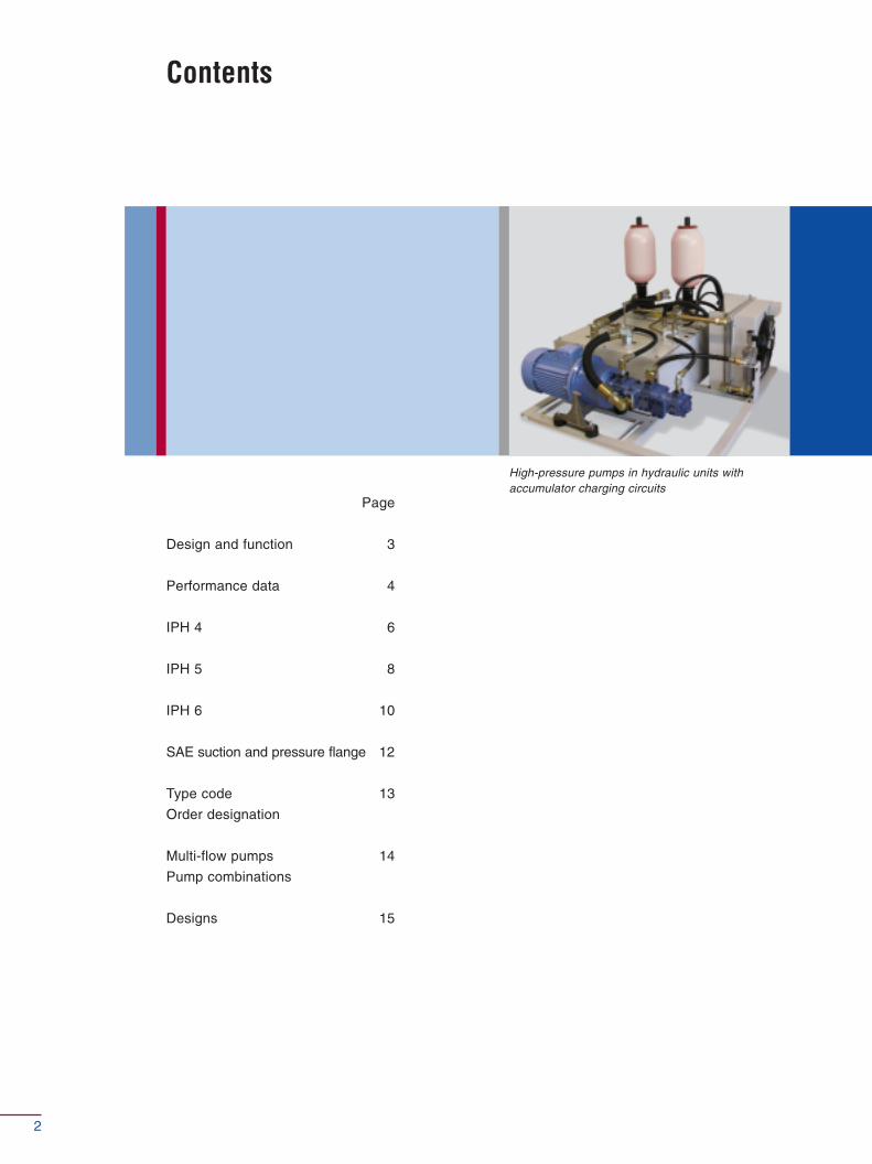
High-pressure pumps in hydraulic units withaccumulator charging circuits
2
Design and function
1 8 5 6 2 9 5 8 2 1 7 6 4 7 310
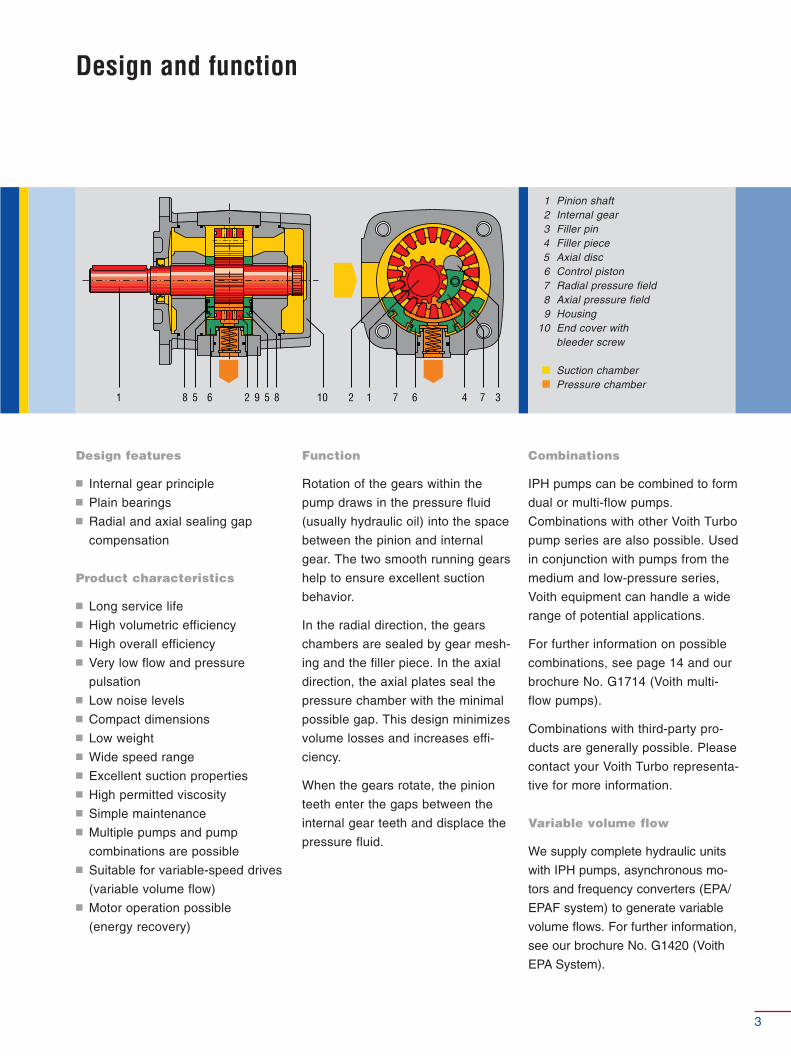
1 Pinion shaft2 Internal gear3 Filler pin4 Filler piece5 Axial disc6 Control piston7 Radial pressure field8 Axial pressure field9 Housing
10 End cover with bleeder screw
Suction chamberPressure chamber
Design features
� Internal gear principle� Plain bearings� Radial and axial sealing gap
compensation
Product characteristics
� Long service life � High volumetric efficiency� High overall efficiency� Very low flow and pressure
pulsation � Low noise levels� Compact dimensions� Low weight� Wide speed range� Excellent suction properties� High permitted viscosity� Simple maintenance � Multiple pumps and pump
combinations are possible� Suitable for variable-speed drives
(variable volume flow)� Motor operation possible
(energy recovery)
Combinations
IPH pumps can be combined to form
dual or multi-flow pumps.
Combinations with other Voith Turbo
pump series are also possible. Used
in conjunction with pumps from the
medium and low-pressure series,
Voith equipment can handle a wide
range of potential applications.
For further information on possible
combinations, see page 14 and our
brochure No. G1714 (Voith multi-
flow pumps).
Combinations with third-party pro-
ducts are generally possible. Please
contact your Voith Turbo representa-
tive for more information.
Variable volume flow
We supply complete hydraulic units
with IPH pumps, asynchronous mo-
tors and frequency converters (EPA/
EPAF system) to generate variable
volume flows. For further information,
see our brochure No. G1420 (Voith
EPA System).
Function
Rotation of the gears within the
pump draws in the pressure fluid
(usually hydraulic oil) into the space
between the pinion and internal
gear. The two smooth running gears
help to ensure excellent suction
behavior.
In the radial direction, the gears
chambers are sealed by gear mesh-
ing and the filler piece. In the axial
direction, the axial plates seal the
pressure chamber with the minimal
possible gap. This design minimizes
volume losses and increases effi-
ciency.
When the gears rotate, the pinion
teeth enter the gaps between the
internal gear teeth and displace the
pressure fluid.
3
Design
Type
Mounting types
Line mounting
Rotation direction
Mounting position
Shaft load
Input pressure
Pressure fluid
Viscosity range of the pressure fluid
Permissible start viscosity
Permissible temperature of the pressure
fluid
Necessary purity of the pressure fluid
in accordance with NAS 1638
Filtration
Permissible ambient temperature
Internal gear pump with radial and axial sealing
gap compensation
IPH
SAE hole flange; ISO 3019/1
SAE suction and pressure flange J 518 C code 61
clockwise or anti-clockwise
any
For details of radial and axial drive shaft loads,
please contact your Voith Turbo representative
0.8 – 3 bar absolute pressure
(at start, briefly 0.6 – 3 bar)
HLP mineral oils DIN 51524, part 2 or 3
10 – 300 mm2s-1 (cSt)
max. 2000 mm2s-1 (cSt)
-20 – +80 °C
Class 8
Filtration quotient min. β20 ≥ 75,
recommended β10 ≥ 100 (longer service life)
-10 – +60 °C
Delivery
Power
Vg th
n
ηηv
ηηg
∆∆p
Technical data Calculations
Performance data
Q = Vg th · n · ηv · 10-3 [l/min]
P =Q · ∆p
[kW]600 · ηg
Pump volume per revolution [cm3]
Speed [min-1]
Volumetric efficiency
Overall efficiency
Differential pressure [bar]
4
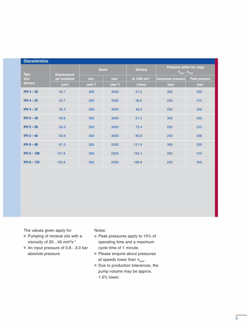
Type, size-delivery
Displacement per revolution
[cm3]
max.
[min-1]
min.
[min-1]
Speed
at 1500 min-1
[l/min]
Delivery
Continuous pressure
[bar]
Peak pressure
[bar]
Pressures within the rangenmin…nmax
IPH 4 – 20 20.7 300 3000 31.0 300 330
IPH 4 – 25 25.7 300 3000 38.6 250 315
IPH 4 – 32 32.3 300 3000 48.5 250 300
IPH 5 – 40 40.8 300 3000 61.2 300 330
IPH 5 – 50 50.3 300 3000 75.4 250 315
IPH 5 – 64 63.9 300 3000 95.8 250 300
IPH 6 – 80 81.3 300 2500 121.9 300 330
IPH 6 – 100 101.6 300 2500 152.4 250 315
IPH 6 – 125 125.6 300 2500 188.8 250 300
Characteristics
The values given apply for:� Pumping of mineral oils with a
viscosity of 20…40 mm2s-1
� An input pressure of 0.8…3.0 bar
absolute pressure
Notes:� Peak pressures apply to 15% of
operating time and a maximum
cycle time of 1 minute.� Please enquire about pressures
at speeds lower than nmin.� Due to production tolerances, the
pump volume may be approx.
1.5% lower.
5
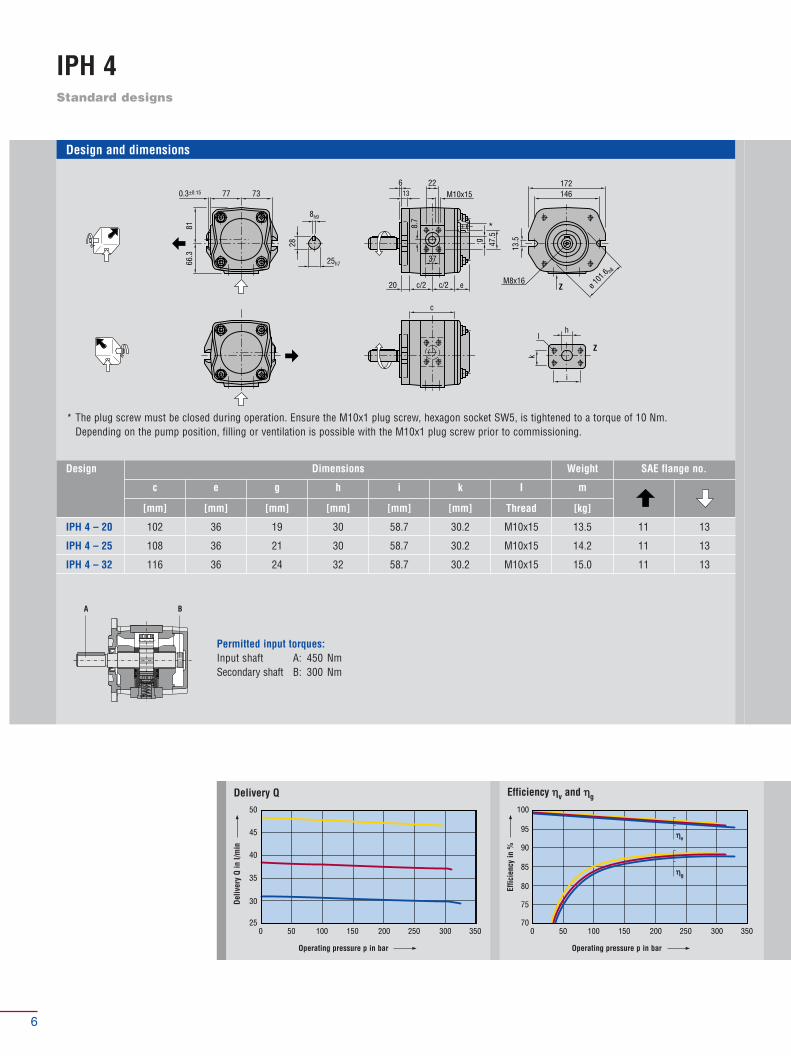
Standard designs
IPH 4
100
700 50 100 150 200 250 300 350
75
80
85
90
95
50
250 50 100 150 200 250 300 350
30
35
40
45
Design and dimensions
* The plug screw must be closed during operation. Ensure the M10x1 plug screw, hexagon socket SW5, is tightened to a torque of 10 Nm.Depending on the pump position, filling or ventilation is possible with the M10x1 plug screw prior to commissioning.
77 7366
.381
0.3±0.15
28
8h9
25h7
613
22
c/2 c/2
8.7
g 47.5
37
20
c
e ø 101
.6 h8
M10x15
M8x16
*
13.5
146172
l
i
h
Z
Z
k
Permitted input torques:Input shaft A: 450 NmSecondary shaft B: 300 Nm
Operating pressure p in bar
Deliv
ery
Q in
l/m
in
Operating pressure p in bar
Effic
ienc
y in
%
Delivery Q Efficiency ηηv and ηηg
ηηv
ηηg
A B
Design Dimensions
c
[mm]
e
[mm]
g
[mm]
h
[mm]
i
[mm]
k
[mm]
I
Thread
m
[kg]
Weight SAE flange no.
IPH 4 – 20
IPH 4 – 25
IPH 4 – 32
102
108
116
36
36
36
19
21
24
30
30
32
58.7
58.7
58.7
30.2
30.2
30.2
M10x15
M10x15
M10x15
13.5
14.2
15.0
11
11
11
13
13
13
6

72
64
72.5
64.5
20
72.5
64.5
90122
ø 101.6h8
90124
1312
ø78
42.5 50
6
64.542.5
64.5
42
64
28
8h9
25h7
20
25
32
IPH 4
Designation according to type code Type code/order designation, see page 13
30
00 50 100 150 200 250 300 350
5
10
15
20
25
70
500 50 100 150 200 250 300 350
55
60
65
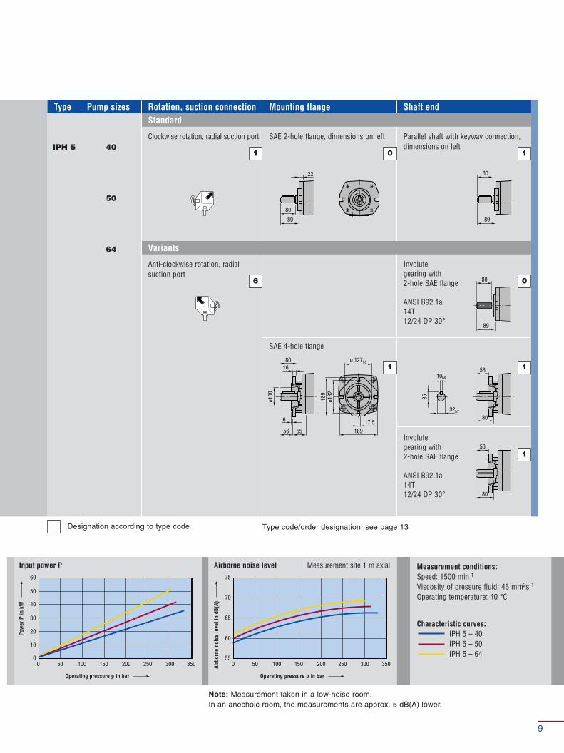
Measurement conditions:Speed: 1500 min-1
Viscosity of pressure fluid: 46 mm2s-1
Operating temperature: 40 °C
Characteristic curves:IPH 4 – 20IPH 4 – 25IPH 4 – 32
Note: Measurement taken in a low-noise room.In an anechoic room, the measurements are approx. 5 dB(A) lower.
Clockwise rotation, radial suction port
1
SAE 2-hole flange, dimensions on left
0
Parallel shaft with keyway connection,dimensions on left
Anti-clockwise rotation, radial suction port
6
SAE 4-hole flange
1
Involutegearing with 2-hole SAE flange
ANSI B92.1a 13T 16/32 DP 30°
Involutegearing with 2-hole SAE flange
ANSI B92.1a 13T 16/32 DP 30°
0
Pump sizes Rotation, suction connectionType Mounting flange Shaft end
Variants
Standard
1
Operating pressure p in bar
Pow
er P
in k
W
Input power P
Operating pressure p in bar
Airb
orne
noi
se le
vel i
n dB
(A)
Airborne noise level Measurement site 1 m axial
1
1
7

Standard designs
IPH 5
Design and dimensions
* The plug screw must be closed during operation. Ensure the M10x1 plug screw, hexagon socket SW5, is tightened to a torque of 10 Nm. Depending on the pump position, filling or ventilation is possible with the M10x1 plug screw prior to commissioning.
95 9886
.810
90.3±0.2
35
10h9
32h7
618
26.2M10x15
c/222 ec/2
11.2
g 52.3
44
c
ø 127 h8
17.5
181210
hl
i
k
Z
Z
*
M12x25
100
700 50 100 150 200 250 300 350
75
80
85
90
95
100
500 50 100 150 200 250 300 350
60
70
80
90
Operating pressure p in bar
Deliv
ery
Q in
l/m
in
Operating pressure p in bar
Effic
ienc
y in
%
Delivery Q Efficiency ηηv and ηηg
ηηv
ηηg
Permitted input torques:Input shaft A: 800 NmSecondary shaft B: 540 Nm
A B
Design Dimensions
c
[mm]
e
[mm]
g
[mm]
h
[mm]
i
[mm]
k
[mm]
I
Thread
m
[kg]
Weight SAE flange no.
IPH 5 – 40
IPH 5 – 50
IPH 5 – 64
138
145
155
35
35
35
24
27
29
35
42
42
70
70
70
36
36
36
M12x19
M12x19
M12x19
26.8
28.3
30
12
12
12
30
30
30
8
Note: Measurement taken in a low-noise room. In an anechoic room, the measurements are approx. 5 dB(A) lower.
60
00 50 100 150 200 250 300 350
10
20
30
40
50
75
550 50 100 150 200 250 300 350
60
65
70
Operating pressure p in bar
Pow
er P
in k
W
Input power P
Operating pressure p in bar
Airb
orne
noi
se le
vel i
n dB
(A)
Airborne noise level Measurement site 1 m axial Measurement conditions:Speed: 1500 min-1
Viscosity of pressure fluid: 46 mm2s-1
Operating temperature: 40 °C
Characteristic curves:IPH 5 – 40IPH 5 – 50IPH 5 – 64
89
80
89
80
22
89
80
17.5189
ø 127h8
ø162
189
16
ø100
56 55
6
80
56
80
56
8035
10h9
32h7
40
50
64
IPH 5
Designation according to type code Type code/order designation, see page 13
Clockwise rotation, radial suction port
1
SAE 2-hole flange, dimensions on left
0
Parallel shaft with keyway connection,dimensions on left
Anti-clockwise rotation, radial suction port
6
SAE 4-hole flange
1
Involutegearing with 2-hole SAE flange
ANSI B92.1a 14T 12/24 DP 30°
Involutegearing with 2-hole SAE flange
ANSI B92.1a 14T 12/24 DP 30°
0
Pump sizes Rotation, suction connectionType Mounting flange Shaft end
Variants
Standard
1
1
1
9

Standard designs
IPH 6
Design and dimensions
* The plug screw must be closed during operation. Ensure the M10x1 plug screw, hexagon socket SW5, is tightened to a torque of 10 Nm. Depending on the pump position, filling or ventilation is possible with the M10x1 plug screw prior to commissioning.
120 12110
6.3
135
0.3±0.2
43
12h9
40h7
5.520.5
36M12x20
c/226.5 e
*
c/2
13.7
g 70
61
c
ø 152
.4 h8
22
228.6264
h
i
k
l
Z
ZM12x25
100
700 50 100 150 200 250 300 350
75
80
85
90
95
210
1100 50 100 150 200 250 300 350
130
150
170
190
Operating pressure p in bar
Deliv
ery
Q in
l/m
in
Operating pressure p in bar
Effic
ienc
y in
%
Delivery Q Efficiency ηηv and ηηg
ηηv
ηηg
Permitted input torques:Input shaft A: 1350 NmSecondary shaft B: 800 Nm
A B
Design Dimensions
c
[mm]
e
[mm]
g
[mm]
h
[mm]
i
[mm]
k
[mm]
I
Thread
m
[kg]
Weight SAE flange no.
IPH 6 – 80
IPH 6 – 100
IPH 6 – 125
171
181
193
49
49
47
32.5
36
39
50
50
50
77.8
77.8
77.8
42.9
42.9
42.9
M12x23
M12x23
M12x23
50.5
54
58
14
14
14
15
15
15
10

Note: Measurement taken in a low-noise room. In an anechoic room, the measurements are approx. 5 dB(A) lower.
120
00 50 100 150 200 250 300 350
20
40
60
80
100
80
600 50 100 150 200 250 300 350
65
70
75
Operating pressure p in bar
Pow
er P
in k
W
Input power P
Operating pressure p in bar
Airb
orne
noi
se le
vel i
n dB
(A)
Airborne noise level Measurement site 1 m axial Measurement conditions:Speed: 1500 min-1
Viscosity of pressure fluid: 46 mm2s-1
Operating temperature: 40 °C
Characteristic curves:IPH 6 – 80IPH 6 – 100IPH 6 – 125
112.5
104
112.5
104
26.5
112
104
22264
ø 152.4h8
ø228
.626
4
20
ø130
63
6
75.5
104
75.5
104
75.5
10443
12h9
40h7
80
100
125
IPH 6
Designation according to type code Type code/order designation, see page 13
Clockwise rotation, radial suction port
1
SAE 2-hole flange, dimensions on left
0
Parallel shaft with keyway connection,dimensions on left
Anti-clockwise rotation, radial suction port
6
SAE 4-hole flange
1
Involutegearing with 2-hole SAE flange
ANSI B92.1a 13T 8/16 DP 30°
Involutegearing with 2-hole SAE flange
ANSI B92.1a 13T 8/16 DP 30°
0
Pump sizes Rotation, suction connectionType Mounting flange Shaft end
Variants
Standard
1
1
1
11
k
iC
BD
A
S2)
E1)
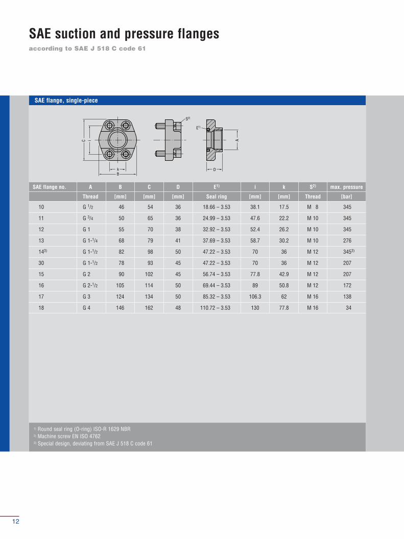
according to SAE J 518 C code 61
SAE suction and pressure flanges
1) Round seal ring (O-ring) ISO-R 1629 NBR2) Machine screw EN ISO 47623) Special design, deviating from SAE J 518 C code 61
SAE flange, single-piece
SAE flange no. A B C D E1) i k S2) max. pressure
Thread [mm] [mm] [mm] Seal ring [mm] [mm] Thread [bar]
10 G 1/2 46 54 36 18.66 – 3.53 38.1 17.5 M 8 345
11 G 3/4 50 65 36 24.99 – 3.53 47.6 22.2 M 10 345
12 G 1 55 70 38 32.92 – 3.53 52.4 26.2 M 10 345
13 G 1-1/4 68 79 41 37.69 – 3.53 58.7 30.2 M 10 276
143) G 1-1/2 82 98 50 47.22 – 3.53 70 36 M 12 3453)
30 G 1-1/2 78 93 45 47.22 – 3.53 70 36 M 12 207
15 G 2 90 102 45 56.74 – 3.53 77.8 42.9 M 12 207
16 G 2-1/2 105 114 50 69.44 – 3.53 89 50.8 M 12 172
17 G 3 124 134 50 85.32 – 3.53 106.3 62 M 16 138
18 G 4 146 162 48 110.72 – 3.53 130 77.8 M 16 34
12
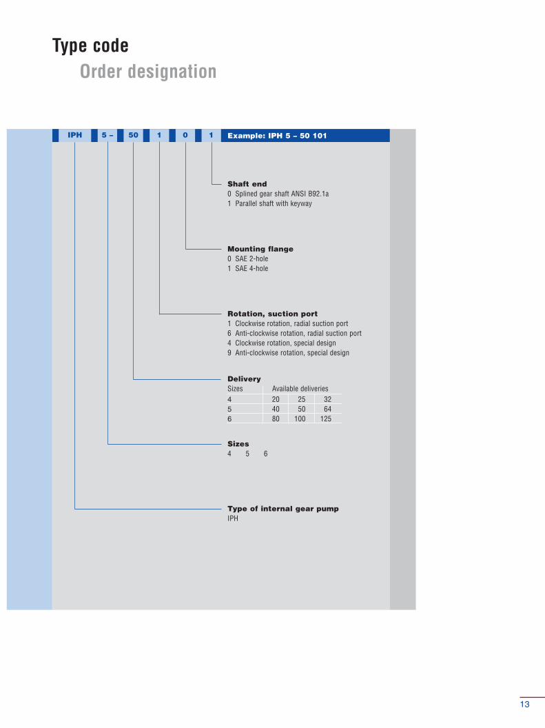
Type codeOrder designation
IPH 5 – 50 1 0 1
Type of internal gear pumpIPH
Shaft end0 Splined gear shaft ANSI B92.1a1 Parallel shaft with keyway
Sizes4 5 6
Rotation, suction port1 Clockwise rotation, radial suction port6 Anti-clockwise rotation, radial suction port4 Clockwise rotation, special design9 Anti-clockwise rotation, special design
Mounting flange0 SAE 2-hole1 SAE 4-hole
Example: IPH 5 – 50 101
DeliverySizes Available deliveries4 20 25 325 40 50 646 80 100 125
13
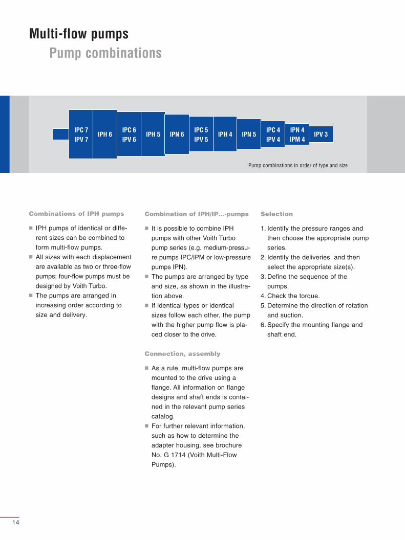
IPC 7IPV 7
IPH 6IPC 6IPV 6
IPH 5 IPN 6IPC 5IPV 5
IPH 4 IPN 5IPC 4IPV 4
IPN 4IPM 4
IPV 3
Multi-flow pumpsPump combinations
Combinations of IPH pumps
� IPH pumps of identical or diffe-
rent sizes can be combined to
form multi-flow pumps.� All sizes with each displacement
are available as two or three-flow
pumps; four-flow pumps must be
designed by Voith Turbo.� The pumps are arranged in
increasing order according to
size and delivery.
Selection
1. Identify the pressure ranges and
then choose the appropriate pump
series.
2. Identify the deliveries, and then
select the appropriate size(s).
3. Define the sequence of the
pumps.
4. Check the torque.
5. Determine the direction of rotation
and suction.
6. Specify the mounting flange and
shaft end.
Combination of IPH/IP…-pumps
� It is possible to combine IPH
pumps with other Voith Turbo
pump series (e.g. medium-pressu-
re pumps IPC/IPM or low-pressure
pumps IPN).� The pumps are arranged by type
and size, as shown in the illustra-
tion above.� If identical types or identical
sizes follow each other, the pump
with the higher pump flow is pla-
ced closer to the drive.
Connection, assembly
� As a rule, multi-flow pumps are
mounted to the drive using a
flange. All information on flange
designs and shaft ends is contai-
ned in the relevant pump series
catalog.� For further relevant information,
such as how to determine the
adapter housing, see brochure
No. G 1714 (Voith Multi-Flow
Pumps).
Pump combinations in order of type and size
14
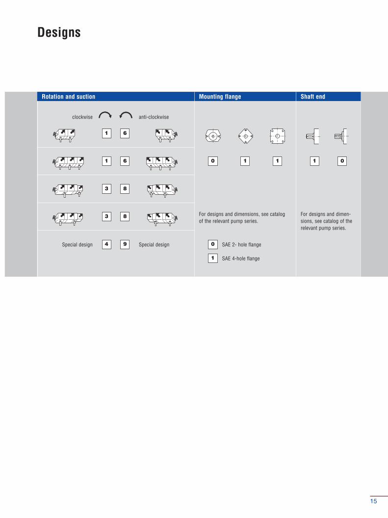
Rotation and suction Mounting flange Shaft end
Designs
Special design Special design
clockwise anti-clockwise
For designs and dimensions, see catalogof the relevant pump series.
For designs and dimen-sions, see catalog of therelevant pump series.
1
1
3
3
6
0 1 1 1 0
0
1
6
8
8
4 9 SAE 2- hole flange
SAE 4-hole flange
15
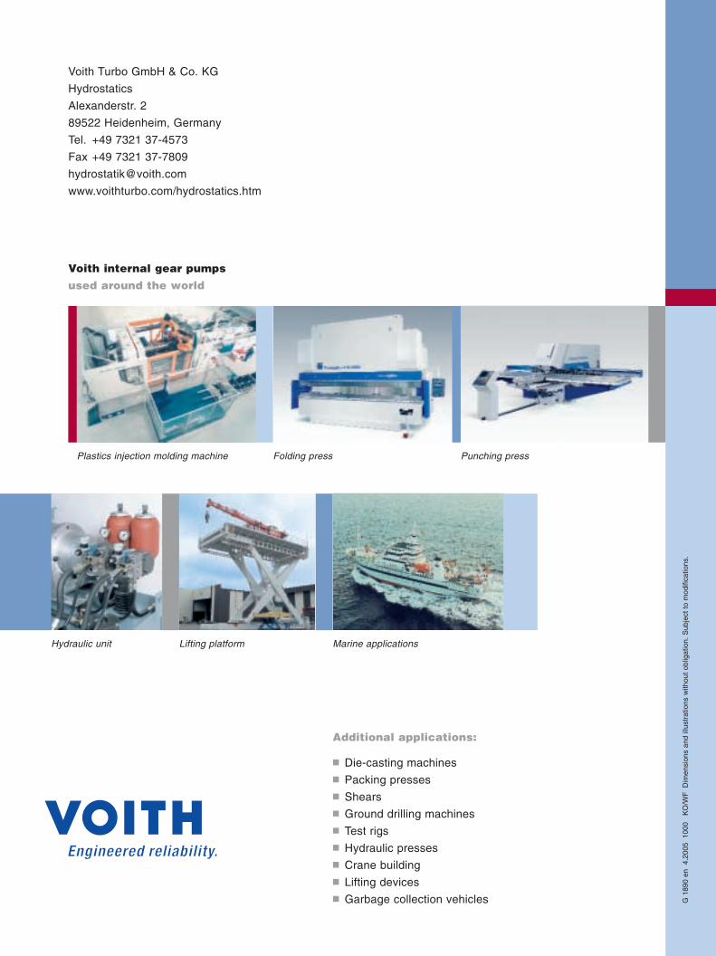
Voith Turbo GmbH & Co. KG
Hydrostatics
Alexanderstr. 2
89522 Heidenheim, Germany
Tel. +49 7321 37-4573
Fax +49 7321 37-7809
www.voithturbo.com/hydrostatics.htm
Plastics injection molding machine Folding press Punching press
Hydraulic unit Lifting platform Marine applications
Additional applications:
� Die-casting machines� Packing presses� Shears� Ground drilling machines� Test rigs� Hydraulic presses� Crane building� Lifting devices� Garbage collection vehicles
Voith internal gear pumps
used around the world
G 1
890
en
4.20
05
1000
K
O/W
FD
imen
sion
s an
d ill
ustr
atio
ns w
ithou
t ob
ligat
ion.
Sub
ject
to
mod
ifica
tions
.