interim survey report: recommendations for … · interim survey report: recommendations for...
TRANSCRIPT
This Survey Report and any recommendations made herein are for the specific facility evaluated and may not be universally applicable. Any recommendations made are not to be considered as final statements of NIOSH policy or of any agency or individual involved. Additional NIOSH Survey Reports are available at http://www.cdc.gov/niosh/surveyreports.
INTERIM SURVEY REPORT:
RECOMMENDATIONS FOR ERGONOMICS INTERVENTIONS
FOR SHIP CONSTRUCTION PROCESSES
at
BATH IRON WORKS CORPORATION SHIPYARD, Bath, Maine
REPORT WRITTEN BY:
Stephen D. Hudock, Ph.D., CSP Steven J. Wurzelbacher, M.S.
Karl Siegfried, MEMIC
REPORT DATE: July 2000
REPORT NO. EPHB 229-13b
U.S. DEPARTMENT OF HEALTH AND HUMAN SERVICES Public Health Service
Centers for Disease Control and Prevention National Institute for Occupational Safety and Health
Division of Applied Research and Technology Engineering and Physical Hazards Branch
4676 Columbia Parkway, Mailstop R-5 Cincinnati, Ohio 45226
Approved for public release; distribution is unlimited Government Purpose Rights

PLANT SURVEYED: Bath Iron Works Corporation shipyard, General Dynamics, 700 Washington Street, Bath, Maine 04530
SIC CODE: 3731
SURVEY DATE: April 17-18, 2000
SURVEY CONDUCTED BY: Stephen D. Hudock, Steven J. Wurzelbacher, Linda Goldenhar, Karl V. Siegfried (MEMIC)
EMPLOYER REPRESENTATIVES CONTACTED:
Allan C. Cameron, President; Kevin Gildart, Vice President, Human Resources
and Public Affairs; Wayne McFarland, Director of Medical and Workers’ Compensation; Dr. Maria Mazorra, Director of Medical Services; Chris Barbor, Occupational Health Nurse
EMPLOYEE REPRESENTATIVES CONTACTED:
Rocky Grenier, IAMS Local S-6
MANUSCRIPT PREPARED BY: Diana R. Flaherty Teri L. Hill
ii

DISCLAIMER
Mention of company names and/or products does not constitute endorsement by the Centers for Disease Control and Prevention (CDC).
iii

ABSTRACT
A pre-intervention quantitative risk factor analysis was performed at various shops and locations at Bath Iron Works shipyard in Bath, Maine as a method to identify and quantify risk factors that workers may be exposed to in the course of their normal work duties. This survey was conducted as part of a larger project, funded through Maritech Advanced Shipbuilding Enterprise and the U.S. Navy, to develop projects to enhance the commercial viability of domestic shipyards. Several operations were identified for further analysis including: unloading of small parts for subassembly, connecting electrical cables at a junction box, pulling cable through the vessel, equipment load-in, insulation installation, welding, and grinding. The application of exposure assessment techniques provided a quantitative analysis of the risk factors associated with the individual tasks. Possible engineering interventions to address these risk factors for each task are examined in this report.
iv
I. INTRODUCTION
IA. BACKGROUND FOR CONTROL TECHNOLOGY STUDIES
The National Institute for Occupational Safety and Health (NIOSH) is the primary Federal agency in occupational safety and health research. Located in the Department of Health and Human Services, it was established by the Occupational Safety and Health Act of 1970. This legislation mandated NIOSH to conduct a number of research and education programs separate from the standard setting and enforcement functions carried out by the Occupational Safety and Health Administration (OSHA) in the Department of Labor. An important area of NIOSH research deals with methods for controlling occupational exposures to potential chemical and physical hazards, including the study of engineering aspects of health hazard prevention and control.
Since 1976, NIOSH had conducted a number of assessments of health hazard control technology on the basis of industry, common industrial process, or specific control techniques. Examples of the completed studies include the foundry industry; various chemical manufacturing or processing operations; spray painting; and the recirculation of exhaust air. The objective of each of these studies had been to document and evaluate effective control techniques for potential health hazards in the industry or process of interest, and to create a more general awareness of the need for or availability of an effective system of hazard control measures.
These studies involve a number of steps or phases. Initially, a series of walk-through surveys is conducted to select plants or processes with effective and potentially transferable control concepts or techniques. Next, in-depth surveys are conducted to determine both the control parameters and the effectiveness of these controls. The reports from these in-depth surveys are then used as a basis for preparing technical reports and journal articles on effective hazard control measures. Ultimately, the information from these research activities builds the data base of publicly available information on hazard control techniques for use by health professionals who are responsible for preventing occupational illness and injury.
IB. BACKGROUND FOR THIS STUDY
The background for this study is reported in “Preliminary Survey Report: Pre-Intervention Quantitative Risk Factor Analysis for Ship Construction Processes at Bath Iron Works Corporation Shipyard, Bath, Maine,” document number EPHB 229-13a by Wurzelbacher et al, 2000.
IC. BACKGROUND FOR THIS SURVEY
Bath Iron Works Corporation was selected as a candidate yard for this study for a number of reasons. In the mid-1990's, a pilot ergonomics intervention project at Bath Iron Works was funded by the National Shipbuilding Research Program. This interest in ergonomics within the
1

shipyard was an indication of the possible cooperativeness in this project. Additionally, it was decided that the project should look at a variety of ship yards based on product, processes and location. Bath Iron Works constructs AEGIS guided missile destroyers for the U.S. Navy and is considered a large shipyard. In fact, Bath Iron Works is the largest private employer in the State of Maine.
II. PLANT AND PROCESS DESCRIPTION
IIA. INTRODUCTION
Plant Description: Bath Iron Works Corporation is located on the Kennebec River in Bath, Maine, approximately thirty miles northeast of Portland, Maine. The main facility of approximately 40 acres includes three inclined shipways able to accommodate ships of 720 feet in length and 112 to 128 feet in breadth or beam. Two principal structural assembly buildings combine for over 208,000 square feet of covered work area providing space for 28 distinct work station locations. The pre-outfit building of about 91,000 square feet provides space for 18 work stations for equipment installation after structural units are blasted and painted. Two cranes, with lifting capacities of 330 and 220 metric tons, service the shipways. Three piers have an overall waterfront length of 2230 feet.
Three other nearby facilities provide additional space for structural fabrication, sub-assembly and final assembly operations, as well as overhaul and repair operations. Currently, Bath Iron Works is in the midst of its most significant facility modernization in its history. A 15-acre expansion into the Kennebec River will include a land-level facility for assembly and erection of ships and a 750-foot floating drydock for the launch and retrieval of ships. It is expected that this new land-level facility will create dramatic process improvements over the current method of construction on inclined building shipways.
Corporate Ties: In 1995, Bath Iron Works was purchased by General Dynamics. The Marine Systems group of General Dynamics includes three ship construction and repair companies (Bath Iron Works, Electric Boat, and NASSCO) and one ship operating company (American Overseas Marine).
Products: Bath Iron Works is the lead designer and builder of the ARLEIGH BURKE class AEGIS guided missile destroyers for the U.S. Navy. These ships are considered to be the most technologically advanced surface combatant ships in the world today. These ships are 505 feet in overall length by 66 feet in beam (width) and displace 8,315 tons under full load. Since the 1950's Bath Iron Works has served as lead shipyard for 10 classes on non-nuclear surface ships for the U.S. Navy, including frigates, cruisers, and destroyers. Bath Iron Works is scheduled to construct an amphibious transport dock ship (LPD) for the U.S. Navy for delivery sometime after 2002. Bath Iron Works has produced over 400 ships since its opening.
2

Age of Plant: Bath Iron Works’ first ship was delivered to the U.S. Navy in 1890. The majority of production facilities have been built in the last 25 years. Facility expansion is underway to provide a land-level assembly area.
Number of Employees, etc: Bath Iron Works employs approximately 7,300 workers. About 4,300 production workers are employed at the main facility. The approximate average age of the production workers is 45 years old.
IIB. PROCESS DESCRIPTION
IIB1. Bin Loading by Material Handlers in the Panel Line Area Process
Pre-cut shapes are shipped into the east end of the panel line from off-site facilities in large metal shipping containers. Shipping containers are delivered by forklift and are placed into the material handling area by utilizing a hand operated pallet jack. Material handlers remove individual pieces from the shipping containers and identify hull, unit and job and other pertinent numbers (Figure 1). Quantity, size, and material are compared with shipping documents to assure accuracy. Once an item has been identified, it is carried and placed onto the appropriate shelf and location marked on receiving documentation (Figure 2). Shapes/pieces are then arranged on the shelves to allow easy retrieval by shipfitters working within the area. Once item has been removed from the bin, checked in, and placed on the appropriate shelf, employee returns to the shipping container, and repeats the process until the bin has been emptied. This walking back to the shipping bin could be considered a rest break from material handling.
Figure 1. Bin Unloader Removing Material from Bin
3
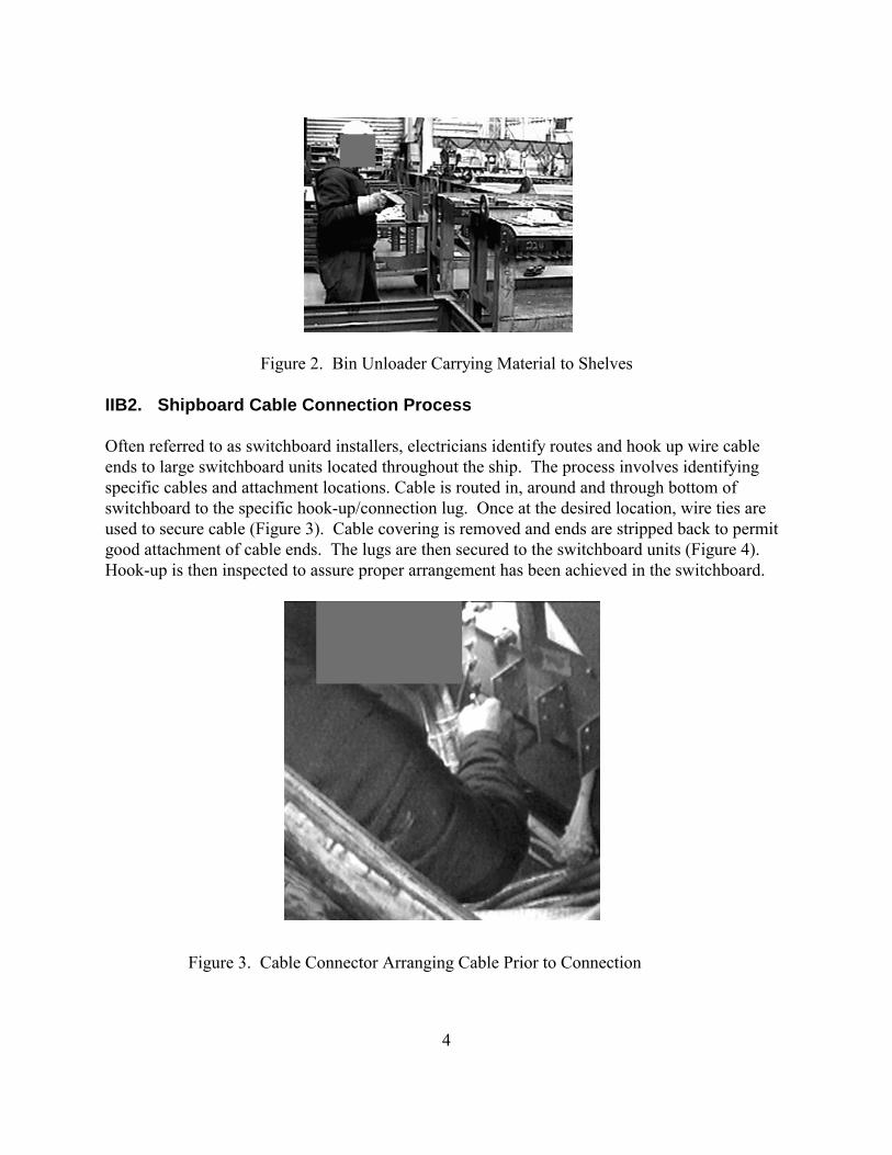
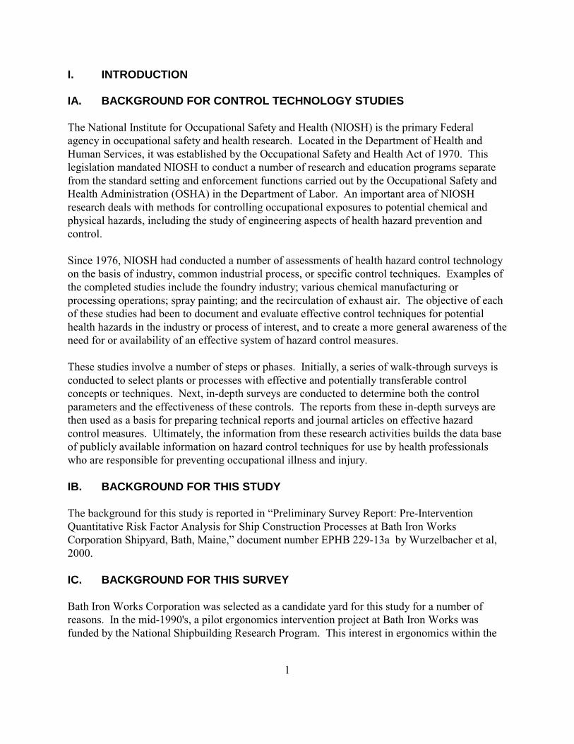
Figure 2. Bin Unloader Carrying Material to Shelves
IIB2. Shipboard Cable Connection Process
Often referred to as switchboard installers, electricians identify routes and hook up wire cable ends to large switchboard units located throughout the ship. The process involves identifying specific cables and attachment locations. Cable is routed in, around and through bottom of switchboard to the specific hook-up/connection lug. Once at the desired location, wire ties are used to secure cable (Figure 3). Cable covering is removed and ends are stripped back to permit good attachment of cable ends. The lugs are then secured to the switchboard units (Figure 4). Hook-up is then inspected to assure proper arrangement has been achieved in the switchboard.
Figure 3. Cable Connector Arranging Cable Prior to Connection
4

Figure 4. Cable Connector Trimming Excess Ties
IIB3. Shipboard Cable Pulling Process
Multiple lines of cable varying in length, size and weight are pulled by hand throughout areas of the ship. The larger cable pulls are performed by workers in groups numbering as high as 20. The size of the crew is largely dependent on the size, length, routing and final location of cable. Both 1.5-inch (approximate dimension) and 0.75-inch cable pulling was analyzed. Cable runs are located overhead, along bulkheads, and below deck plate level. All cable is secured into cable trays and tagged whenever passing through a bulkhead or deck. When running from one deck to another, the cable passes through transits, which are later packed to assure an air- and water-tight seal. Once cable reaches the transit, or bulkhead oval (cutout), it is routed through the structure and secured using cable ties. This often requires forceful pulling while in an awkward posture. Cable is routed fed through cable trays until the final destination is reached. Cable pulling is performed in a variety of postures, including seated , as in Figure 5, and overhead, as shown in Figures 6 and 7. Whenever cable passes through a bulkhead or deck it must be labeled for identification purposes. A label is pre-cut and marked. A small banding device is used to secure the label to the cable. Cables must also be tied to the cable tray utilizing plastic ties.
5
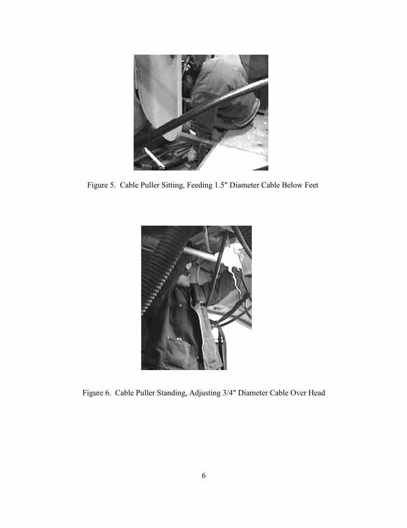
Figure 5. Cable Puller Sitting, Feeding 1.5" Diameter Cable Below Feet
Figure 6. Cable Puller Standing, Adjusting 3/4" Diameter Cable Over Head
6

Figure 7. Cable Puller Standing, Feeding 3/4" Diameter Cable Over Head
IIB4. Shipboard Rigger Equipment Load-In Process Equipment is lifted off of the transportation vehicle via a large gantry crane and lowered into the ship. Depending on the final location of equipment and location of access hole, the degree of manual manipulation of the object will vary. Two groups of riggers exist within the shipyard. Those who work with the gantry crane operators are often referred to as dock riggers. Their job responsibilities include rigging loads safely and being in visual and/or verbal contact with the crane operator. Some truck drivers also rig up lifts. The employees who perform work tasks within the ship, i.e. moving equipment through compartments, are often referred to as shipboard riggers. Once the equipment is unhooked from the crane, shipboard riggers are responsible for getting the equipment/item to its final position. Comparing the dock and shipboard riggers, by far the shipboard employees perform the more physically demanding group of job tasks. Equipment is lowered into an access hole located on the bow. A tag line is used to safely guide the load down to the shipboard riggers located below deck (Figure 8). Shipboard riggers roll the equipment into the general vicinity of its final destination using low cart rollers, which are very effective for moving equipment over flat decks with no lips or protrusions. Unfortunately, only a few areas within the ship are suitable for this mode of transport. Once the equipment or item is close to its final destination, or needs to move off of the low profile cart, it is slid across the deck (Figure 9). When feasible, shipboard riggers place a one-inch pipe under the equipment permitting it to be rolled with less effort (Figure 10). To place or remove th e pipe roller from underneath the equipment, the item being moved must be tilted on one end, which permits the roller device to be set in place. Once the equipment or item is in place, the process repeats until truck is unloaded.
7

Figure 8. Lowering Equipment Through Hatch
Figure 9. Sliding Equipment Off Cart
8

Figure 10. Rolling Equipment in on Pipe Rollers
IIB5. Shipboard Insulation Installation Process
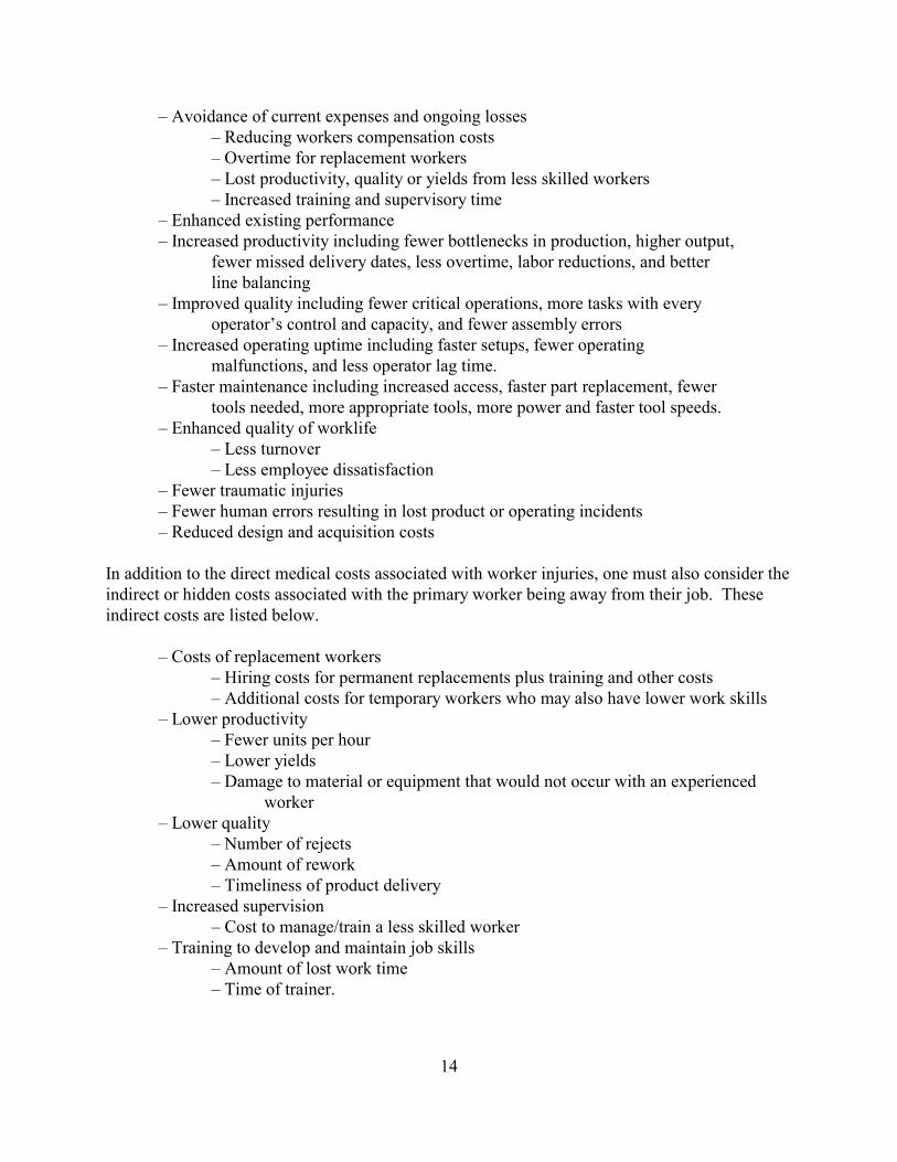
Insulators usually work in teams consisting of one installer and one cutter. The installer measures the area to be covered and relays this information to the cutter, who measures, marks and cuts the piece of insulation to size (Figure 11). The piece is then handed up or over to the installer who may re-measure the piece (Figure 12), pushes the insulation into place, piercing the insulation material onto the insulation stud. The installer then installs a cap over the end of the stud securing it with a hammer strike (Figure 13). Installers and cutters will trade places from day to day. It is common for installers to work off of stepladders when performing overhead and some bulkhead installation. Cutters usually set up makeshift workbenches using several boxes of the insulation and/or sawhorses. Most of the insulation is a foam type of material, however, some fiberglass is still used. Sheets are usually 2 feet by 4 feet.
Figure 11. Insulator Cutter Using Knife to Cut Insulation
9
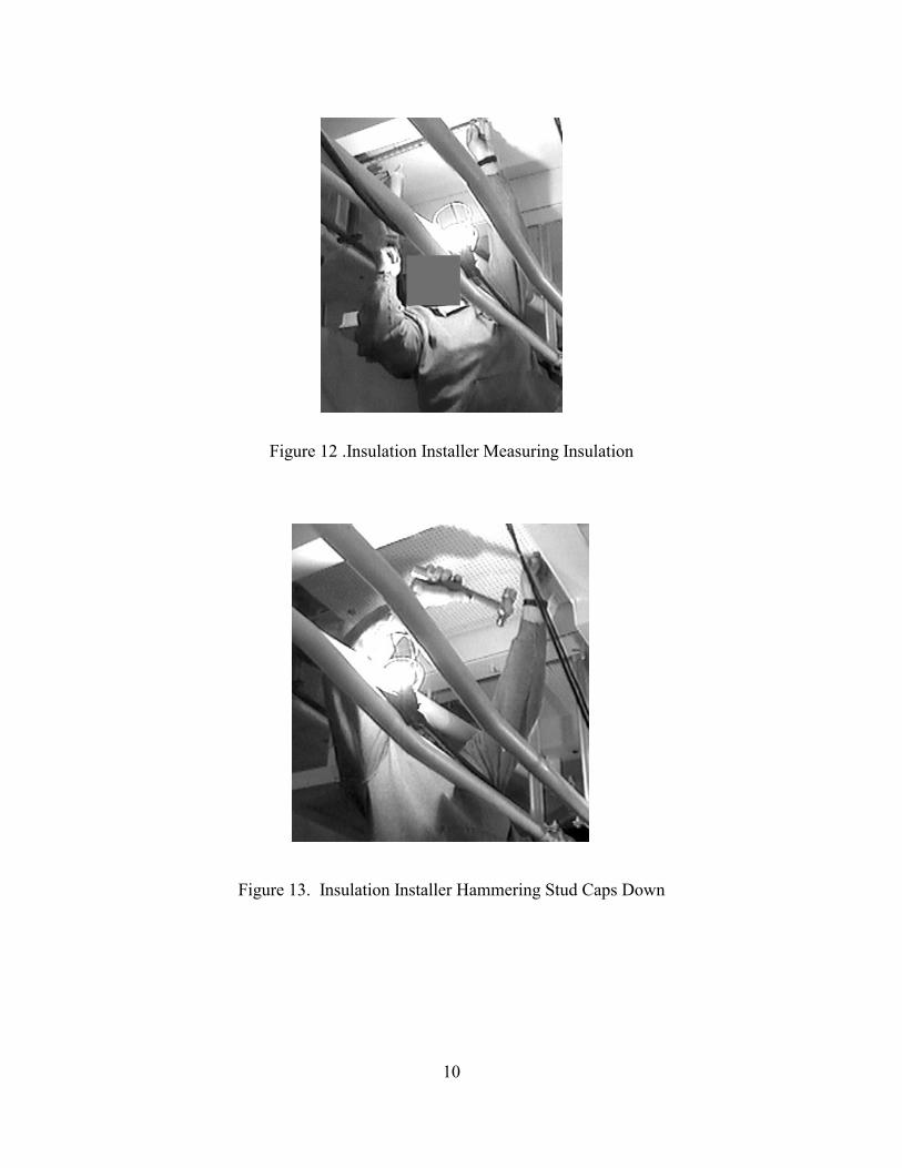
Figure 12 .Insulation Installer Measuring Insulation
Figure 13. Insulation Installer Hammering Stud Caps Down
10

IIB6. Wire Welding in Panel Line Process
Welders working in the panel line building are responsible for welding sheets and other structural members to form bulkheads, decks and overhead units. Items to be welded have been tacked into place by the shipfitters. If necessary, welders grind the area to remove any foreign debris and using wire welding equipment performs the welding operation. Once a bead has been run, it is cleaned using a slag hammer, offset wire brush or other pneumatic tool. Most work in the panel line is performed in the downward position. It is common for welders to sit, kneel, crouch, bend and even lay down on the steel when welding.
Figure 14. Panel Line Welder Wire Welding
IIB7. Shipboard Tank Grinding Process
Primary responsibilities include removing paint, rust and other foreign objects from tanks, the bilge, bulkheads, etc. The main purpose is to prepare surface for painting. In some areas all paint is removed while in others a feathered edge is created. Tank grinders use multiple pneumatic tools, depending on specific task to be completed and available work space. The most common pneumatic tools used include the 5- and 3-inch disc sanders (Figures 15 and 16), offset wire brush and needle gun (Figure 17). After the area has been ground, it is cleaned using various cleaning solutions.
11

Figure 15. Tank Grinder Using 5-Inch Offset Grinder
Figure 16. Tank Grinder Using 3 inch Offset Grinder
12

Figure 17. Tank Grinder Using Needle Gun Overhead
III. ERGONOMIC INTERVENTION COST JUSTIFICATION
The following section has been adapted from the article by Alexander, 1998. The effectiveness of any ergonomic intervention does not necessarily correlate with the cost of implementing that intervention. The possibility exists for a very effective intervention to be found at a low implementation cost, as well as, the possibility of the opposite. The preferred intervention strategy from a business sense is to implement those interventions with the lowest costs and the highest effectiveness (Figure 18).
Figure 18. Value Cost Matrix
There are a number of benefits that can be credited to the application of ergonomic interventions in general. These benefits are listed below.
13
– Avoidance of current expenses and ongoing losses – Reducing workers compensation costs – Overtime for replacement workers – Lost productivity, quality or yields from less skilled workers – Increased training and supervisory time
– Enhanced existing performance – Increased productivity including fewer bottlenecks in production, higher output,
fewer missed delivery dates, less overtime, labor reductions, and better line balancing
– Improved quality including fewer critical operations, more tasks with every operator’s control and capacity, and fewer assembly errors
– Increased operating uptime including faster setups, fewer operatingmalfunctions, and less operator lag time.
– Faster maintenance including increased access, faster part replacement, fewer tools needed, more appropriate tools, more power and faster tool speeds.
– Enhanced quality of worklife – Less turnover – Less employee dissatisfaction
– Fewer traumatic injuries – Fewer human errors resulting in lost product or operating incidents – Reduced design and acquisition costs
In addition to the direct medical costs associated with worker injuries, one must also consider the indirect or hidden costs associated with the primary worker being away from their job. These indirect costs are listed below.
– Costs of replacement workers – Hiring costs for permanent replacements plus training and other costs – Additional costs for temporary workers who may also have lower work skills
– Lower productivity – Fewer units per hour – Lower yields – Damage to material or equipment that would not occur with an experienced
worker – Lower quality
– Number of rejects – Amount of rework – Timeliness of product delivery
– Increased supervision – Cost to manage/train a less skilled worker
– Training to develop and maintain job skills – Amount of lost work time – Time of trainer.
14
Many of these indirect costs are difficult to estimate and can vary widely depending on the severity of the injury involved. The ratio of indirect costs to direct costs has also been found by a number of studies to vary between 5:1 to 1:5, depending on industry (Heinrich, 1931, 1959; Levitt et al, 1981; Andreoni, 1986; Leopold and Leonard, 1987; Klen, 1989; Hinze and Applegate, 1991; Oxenburgh, 1991, 1993). As a conservative estimate, the state of Washington recently decided upon indirect costs of 75 percent of direct workers’ compensation incurred costs (WAC 296-62-051, 2000).
Another aspect of ergonomic interventions that must be considered is the cost benefit analysis. If total costs outweigh all benefits received from implementing the intervention, then the intervention is not worth undertaking. One has to determine the associated start-up costs, recurring costs, and salvage costs of the intervention as well as the time value of money (present worth versus future worth) and the company’s Minimum Attractive Rate of Return, the interest rate the company is willing to accept for any project of financial undertaking.
IV. CONTROL TECHNOLOGY
IVA. PANEL LINE BIN LOADING BY MATERIAL HANDLERS POSSIBLE INTERVENTIONS
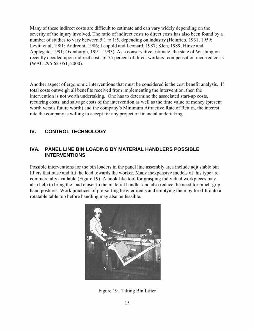
Possible interventions for the bin loaders in the panel line assembly area include adjustable bin lifters that raise and tilt the load towards the worker. Many inexpensive models of this type are commercially available (Figure 19). A hook-like tool for grasping individual workpieces may also help to bring the load closer to the material handler and also reduce the need for pinch-grip hand postures. Work practices of pre-sorting heavier items and emptying them by forklift onto a rotatable table top before handling may also be feasible.
Figure 19. Tilting Bin Lifter
15
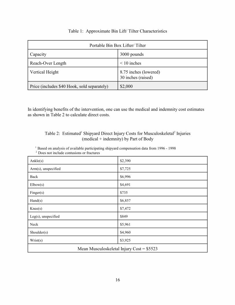
Table 1: Approximate Bin Lift/ Tilter Characteristics
Portable Bin Box Lifter/ Tilter
Capacity 3000 pounds
Reach-Over Length < 10 inches
Vertical Height 8.75 inches (lowered) 30 inches (raised)
Price (includes $40 Hook, sold separately) $2,000
In identifying benefits of the intervention, one can use the medical and indemnity cost estimates as shown in Table 2 to calculate direct costs.
Table 2: Estimated1 Shipyard Direct Injury Costs for Musculoskeletal2 Injuries (medical + indemnity) by Part of Body
1 Based on analysis of available participating shipyard compensation data from 1996 - 1998 2 Does not include contusions or fractures
Ankle(s) $2,390
Arm(s), unspecified $7,725
Back $6,996
Elbow(s) $4,691
Finger(s) $735
Hand(s) $6,857
Knee(s) $7,472
Leg(s), unspecified $849
Neck $5,961
Shoulder(s) $4,960
Wrist(s) $3,925
Mean Musculoskeletal Injury Cost = $5523
16

From 1996 to 1998 BIW experienced at least twenty musculoskeletal injuries to material handlers working on bin loading type tasks in the fabrication area. The total estimated medical and indemnity cost of these injuries was $125,103, based upon the above shipyard industry average costs by part of body injured. If the twenty injuries can be said to be due to the specific bin loading task in the panel line area, the average annual estimate direct cost (over the last three years) for musculoskeletal injuries that may be preventable by measures to relieve the postures and stresses associated with this task is $41,701. If indirect costs are conservatively assumed to be 75% of the direct costs, the total cost of these injuries per year is $72,977. It is this amount that can be considered an “avoided cost” and, therefore, a benefit due to the implementation of the intervention. Assuming, the intervention fully eliminates such injuries, a simple benefit to cost ratio would be $72,977/$2,000 or 36.5. Since the benefit to cost ratio is greater than one, it is advantageous and cost-effective to implement the proposed intervention. However it is possible that only one-tenth of the estimated annual injury cost is saved each year. It is also possible that the bin tilter lasts 2 years. Assuming that the shipyard has a minimum attractive rate of return of 20 percent for any project cash outlay, one can still calculate a benefit to cost ratio by utilizing the following equation to determine the present worth of an annual savings:
n[(1+ i) − 1]Equation 1: PW = AS × ni × (1+ i)
where PW = present worthAS = annual savingsi = interest rate (ex., 0.20 for 20 percent), andn = number of years.
Using an annual savings of just $7,298 (one-tenth of the estimated annual injury cost) at an interest rate of 20 percent over a two year period, the present worth of the proposed savings would be $11,150. Assuming initial costs of the bin tilter/ hook are $2,000 and negligible annual costs, the benefit to cost ratio of implementing this intervention is $11,150/$2,000 or 5.57, greater than one, and therefore still economically advantageous.
IVB. SHIPBOARD CABLE CONNECTORS POSSIBLE INTERVENTIONS
Possible interventions for the shipboard cable connectors include work practices which reduce the amount of cable preparation (stripping, tying etc...) at the switchboard, where the confined space limits work movements and postures. The use and maintenance of specialized cable tools may also reduce grip and other upper extremity forces.
IVC. SHIPBOARD CABLE PULLERS POSSIBLE INTERVENTIONS
Possible interventions for the shipboard cable pullers include work rotation among pullers so that time spent in postures involving overhead work, kneeling, and back flexion are minimized and
17
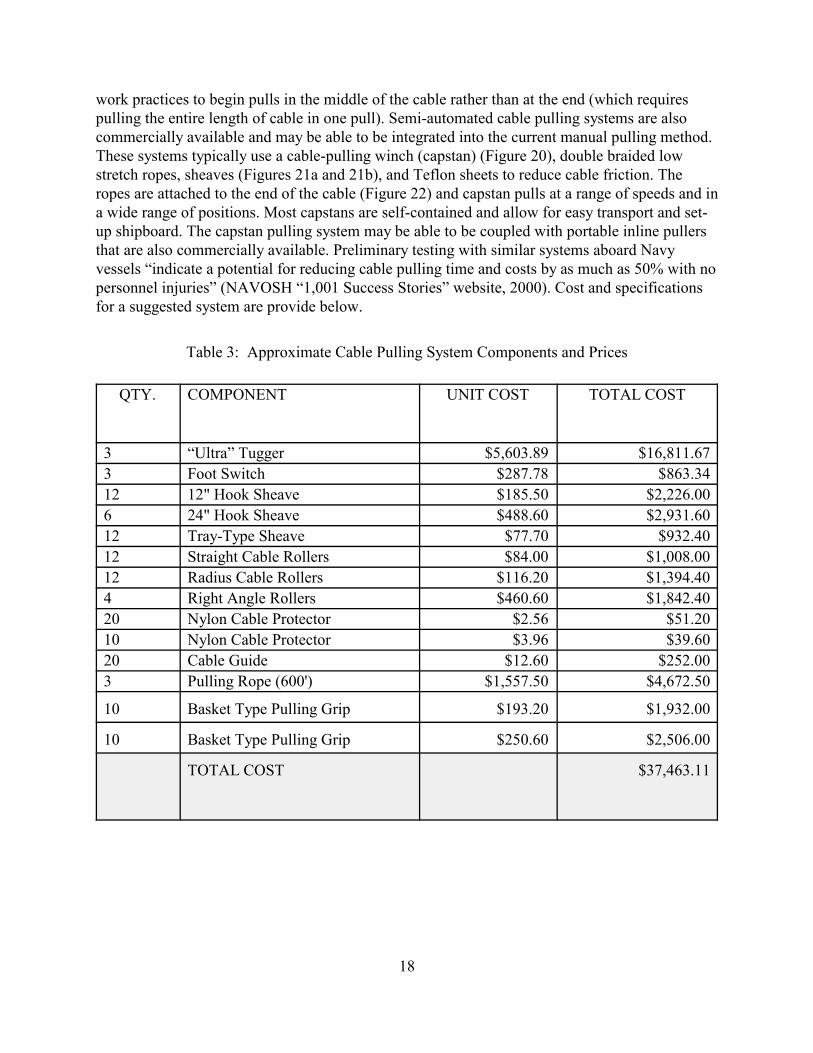
work practices to begin pulls in the middle of the cable rather than at the end (which requires pulling the entire length of cable in one pull). Semi-automated cable pulling systems are also commercially available and may be able to be integrated into the current manual pulling method. These systems typically use a cable-pulling winch (capstan) (Figure 20), double braided low stretch ropes, sheaves (Figures 21a and 21b), and Teflon sheets to reduce cable friction. The ropes are attached to the end of the cable (Figure 22) and capstan pulls at a range of speeds and in a wide range of positions. Most capstans are self-contained and allow for easy transport and set-up shipboard. The capstan pulling system may be able to be coupled with portable inline pullers that are also commercially available. Preliminary testing with similar systems aboard Navy vessels “indicate a potential for reducing cable pulling time and costs by as much as 50% with no personnel injuries” (NAVOSH “1,001 Success Stories” website, 2000). Cost and specifications for a suggested system are provide below.
Table 3: Approximate Cable Pulling System Components and Prices
QTY. COMPONENT UNIT COST TOTAL COST
3 “Ultra” Tugger $5,603.89 $16,811.67 3 Foot Switch $287.78 $863.34 12 12" Hook Sheave $185.50 $2,226.00 6 24" Hook Sheave $488.60 $2,931.60 12 Tray-Type Sheave $77.70 $932.40 12 Straight Cable Rollers $84.00 $1,008.00 12 Radius Cable Rollers $116.20 $1,394.40 4 Right Angle Rollers $460.60 $1,842.40 20 Nylon Cable Protector $2.56 $51.20 10 Nylon Cable Protector $3.96 $39.60 20 Cable Guide $12.60 $252.00 3 Pulling Rope (600') $1,557.50 $4,672.50
10 Basket Type Pulling Grip $193.20 $1,932.00
10 Basket Type Pulling Grip $250.60 $2,506.00
TOTAL COST $37,463.11
18
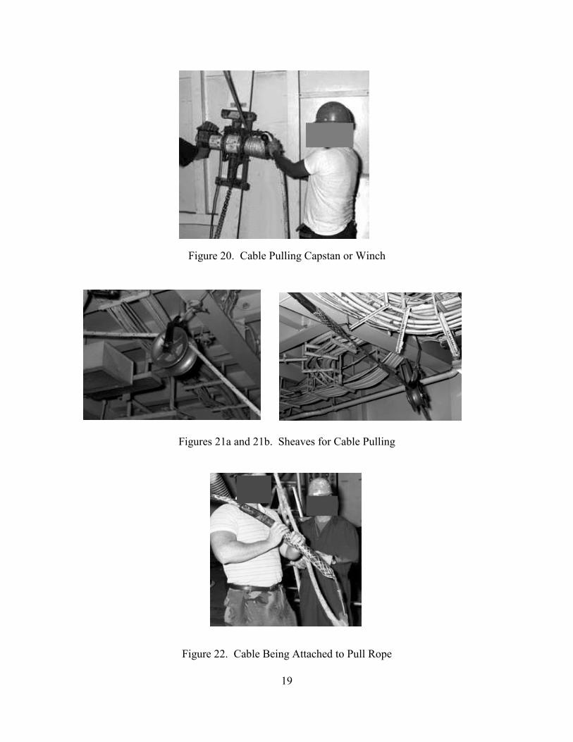
Figure 20. Cable Pulling Capstan or Winch
Figures 21a and 21b. Sheaves for Cable Pulling
Figure 22. Cable Being Attached to Pull Rope
19
In identifying benefits of the intervention, one can use the medical and indemnity cost estimates as shown in Table 2 to calculate direct costs. From 1996 to 1998 BIW experienced at least ninety-one musculoskeletal injuries to shipboard cable pullers. The total estimated medical and indemnity cost of these injuries was $540,689, based upon the above shipyard industry average costs by part of body injured. If the ninety-one injuries can be said to be due to the specific cable pulling tasks studied, the average annual estimate direct cost (over the last three years) for musculoskeletal injuries that may be preventable by measures to relieve the postures and stresses associated with this task is $180,230. If indirect costs are conservatively assumed to be 75% of the direct costs, the total cost of these injuries per year is $315,402. It is this amount that can be considered an “avoided cost” and, therefore, a benefit due to the implementation of the intervention. Assuming, the intervention fully eliminates such injuries, a simple benefit to cost ratio would be $315,402/$37,463 or 8.42. Since the benefit to cost ratio is greater than one, it is advantageous and cost-effective to implement the proposed intervention. However it is possible that only one-tenth of the estimated annual injury cost is saved each year. It is also possible that the cable pulling system lasts 2 years. Assuming that the shipyard has a minimum attractive rate of return of 20 percent for any project cash outlay, one can still calculate a benefit to cost ratio by utilizing the following equation to determine the present worth of an annual savings:
n[(1+ i) − 1]Equation 1: PW = AS × ni × (1+ i)
where PW = present worthAS = annual savingsi = interest rate (ex., 0.20 for 20 percent), andn = number of years.
Using an annual savings of just $31,540 (one-tenth of the estimated annual injury cost) at an interest rate of 20 percent over a two year period, the present worth of the proposed savings would be $48,186. Assuming initial costs of the cable pulling system are $37,463 and negligible annual costs, the benefit to cost ratio of implementing this intervention is $48,186/$37,463 or 1.29, greater than one, and therefore still economically advantageous.
IVD. EQUIPMENT LOAD-IN BY SHIPBOARD RIGGERS POSSIBLE INTERVENTIONS
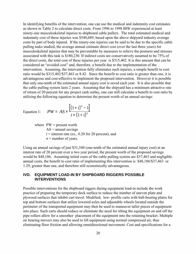
Possible interventions for the shipboard riggers during equipment load-in include the work practice of preparing the temporary deck surface to reduce the number of uneven plate and plywood surfaces that inhibit cart travel. Modified, low- profile carts with ball-bearing plates for top and bottom surfaces that utilize lowered axles and adjustable wheels located outside the perimeter of the transported equipment may then be used to maneuver taller pieces of equipment into place. Such carts should reduce or eliminate the need for tilting the equipment on and off the pipe rollers allow for a smoother placement of the equipment into the retaining bracket. Multiple air bearing movers may also be used to lift equipment using normal compressed air, thus eliminating floor friction and allowing omnidirectional movement. Cost and specifications for a
20
suggested system are provide below.
Table 4: Approximate Air Bearing Mover Characteristics
Capacity up to 7,000 lb
Dimensions 21" x 21" x 2"
Lifting Height 1 1/8"
Air Use 16 CFM; 90-115 psi required
Air inlet 3/4" NPT
Price $890 x 3 = $2,670
In identifying benefits of the intervention, one can use the medical and indemnity cost estimates as shown in Table 2 to calculate direct costs. From 1996 to 1998 BIW experienced at least sixteen musculoskeletal injuries to shipboard equipment loaders. The total estimated medical and indemnity cost of these injuries was $105,942, based upon the above shipyard industry average costs by part of body injured. If the sixteen injuries can be said to be due to the specific equipment load-in task studied, the average annual estimate direct cost (over the last three years) for musculoskeletal injuries that may be preventable by measures to relieve the postures and stresses associated with this task is $35,314. If indirect costs are conservatively assumed to be 75% of the direct costs, the total cost of these injuries per year is $61,800. It is this amount that can be considered an “avoided cost” and, therefore, a benefit due to the implementation of the intervention. Assuming, the intervention fully eliminates such injuries, a simple benefit to cost ratio would be $61,800/$2,670 or 23.15. Since the benefit to cost ratio is greater than one, it is advantageous and cost-effective to implement the proposed intervention. However it is possible that only one-tenth of the estimated annual injury cost is saved each year. It is also possible that the air bearing system lasts 2 years. Assuming that the shipyard has a minimum attractive rate of return of 20 percent for any project cash outlay, one can still calculate a benefit to cost ratio by utilizing the following equation to determine the present worth of an annual savings:
n[(1+ i) − 1]Equation 1: PW = AS × ni × (1+ i)
where PW = present worthAS = annual savingsi = interest rate (ex., 0.20 for 20 percent), andn = number of years.
21

Using an annual savings of just $6,180 (one-tenth of the estimated annual injury cost) at an interest rate of 20 percent over a two year period, the present worth of the proposed savings would be $9,442. Assuming initial costs of the cable pulling system are $2,670 and negligible annual costs, the benefit to cost ratio of implementing this intervention is $9,442/$2,670 or 3.54, greater than one, and therefore still economically advantageous.
IVE. SHIPBOARD INSULATORS POSSIBLE INTERVENTIONS
Possible interventions for the shipboard insulators (cutters) include angled knives to maintain neutral wrist postures. Possible interventions for the shipboard insulators (installers) include an alternate insulation securing process involving semi-automatic stud guns or re-designed knives and hammers. Work rotation between the cutters and installers may also reduce the time spent in overhead postures by the worker performing the installation task.
IVF. PANEL LINE WELDING POSSIBLE INTERVENTIONS
Possible interventions for the panel line welders include the use of low profile, wheeled carts or stools as movable seats for the welders to reduce back flexion and the need to assume kneeling postures (Figures 23a and 23b). Such carts may be able to be custom designed to include upper body supports and knee supports that allow a variety of postures, such as semi-sitting or kneeling and leaning forward. Knee pads and thigh-supports (Figure 24) to prevent hyperflexion of the knees during squatting are also commercially available.
Figures 23a and 23b. Closeups of Worker Cart and Stool
22
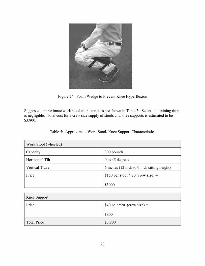
Figure 24. Foam Wedge to Prevent Knee Hyperflexion
Suggested approximate work stool characteristics are shown in Table 5. Setup and training time is negligible. Total cost for a crew size supply of stools and knee supports is estimated to be $3,800.
Table 5: Approximate Work Stool/ Knee Support Characteristics
Work Stool (wheeled)
Capacity 300 pounds
Horizontal Tilt 0 to 45 degrees
Vertical Travel 6 inches (12 inch to 6 inch sitting height)
Price $150 per stool * 20 (crew size) =
$3000
Knee Support
Price $40 pair *20 (crew size) =
$800
Total Price $3,800
23
From 1996 to 1999 BIW experienced four back injuries and twenty knee injuries to welders (working on tasks similar to panel line welding) that were not due to lifting or falls. The total estimated medical and indemnity cost of these injuries was $177,424, based upon the above shipyard industry average costs by part of body injured. If the twenty-four injuries can be said to be due to poor postures and contact stress, the average annual estimate direct cost (over the last three years) for musculoskeletal injuries that may be preventable by measures to relieve these postures and stresses is $59,141. If indirect costs are conservatively assumed to be 75% of the direct costs, the total cost of these injuries per year is $103,497. It is this amount that can be considered an “avoided cost” and, therefore, a benefit due to the implementation of the intervention. Assuming, the intervention fully eliminates such injuries, a simple benefit to cost ratio would be $103,497/$3,800 or 27. Since the benefit to cost ratio is greater than one, it is advantageous and cost-effective to implement the proposed intervention. However it is possible that only one-tenth of the estimated annual injury cost is saved each year. It is also possible that the weld stools/ knee supports last only 6 months. Assuming that the shipyard has a minimum attractive rate of return of 20 percent for any project cash outlay, one can still calculate a benefit to cost ratio by utilizing the following equation to determine the present worth of an annual savings:
n[(1+ i) − 1]Equation 1: PW = AS × ni × (1+ i)
where PW = present worthAS = annual savingsi = interest rate (ex., 0.20 for 20 percent), andn = number of years.
Using an annual savings of just $10,350 (one-tenth of the estimated annual injury cost) at an interest rate of 20 percent over a half year period, the present worth of the proposed savings would be $4,509. Assuming initial costs of the weld stools/ knee supports are $3,800 and negligible annual costs, the benefit to cost ratio of implementing this intervention is $4,509/$3,800 or 1.19, greater than one, and therefore still economically advantageous.
IVG. SHIPBOARD TANK GRINDERS POSSIBLE INTERVENTIONS
Possible interventions for the shipboard tank grinders include lighter tools that induce less vibration and the use of support devices such as spring returns for areas where extended vertical grinding is required. Appropriate tool balancers cost in the range of about $50-150. Process changes (e.g. weldable primer, more efficient and clean welding processes) to reduce the amount of required grinding may also be explored. Portable, self-contained abrasive blasting units may also be able to be used instead of manual grinding in some cases.
24

V. CONCLUSIONS AND RECOMMENDATIONS
Seven work processes within Bath Iron Works were surveyed to determine the presence of risk factors associated with musculoskeletal disorders. These processes included panel line bin un-loading, shipboard cable connecting, shipboard cable pulling, shipboard equipment load-in, shipboard insulation cutting and installing, panel line welding, and shipboard tank grinding. In each process, certain work elements were found to be associated with one or more factors, including excessive force, constrained or awkward postures, contact stresses, vibration, and repetitive motions.
It is recommended that further action be taken to mitigate the exposure to musculoskeletal risk factors within each of the identified tasks. The implementation of ergonomic interventions has been found to reduce the amount and severity of musculoskeletal disorders within the working population in various industries. It is suggested that ergonomic interventions may be implemented at Bath Iron Works facilities to minimize hazards in the identified job tasks, as has already been done in a number of different locations throughout the shipyard.
25
VI. REFERENCES
Alexander, D. C. Strategies for Cost Justifying Ergonomic Improvements. IIE Soultions, Institute of Industrial Engineers, Norcross, Georgia, March 1998, 30(3):30-35.
Andreoni, D. The Costs of Occupational Accidents and Diseases. Geneva: International Labor Office; 1986
Heinrich, H.W. Industrial Accident Prevention: A Scientific Approach. 4th Edition. New York: Wiley; 1959
Hinze, J. And Applegate, L.L. Costs of Construction Injuries. Journal of Construction Engineering and Management. 1991; 117(3): 537-550.
Klen, T. Costs of Occupational Accidents in Forestry. Journal of Safety Research. 1989; 20(31):31-40.
Leopold, E. And Leonard, S. Costs of Construction Accidents to Employers. Journal of Occupational Accidents. 1987; 8:273-294.
Levitt, R.E. Improving Construction Safety Performance; 1982 Jan; Report A-3.
Oxenburgh, M. Increasing Productivity and Profit Through Health and Safety. Austrailia: CCH International; 1991
Oxenburgh, M.S. and Guldberg, H.H. The Economic and Health Effects on Introducing a Safe Manual Handling Code of Practice. International Journal of Industrial Ergonomics. 1993; 12:241-253.
Washington State Ergonomics Rule. WAC 296-62-051. (2000)
Wurzelbacher, S. J., K. V. Siegfried, and S. D. Hudock. Preliminary Survey Report: Pre-Intervention Quantitative Risk Factor Analysis for Ship Construction Processes at Bath Iron Works Corporation Shipyard, Bath, Maine. DHHS, PHS, CDC, NIOSH, Cincinnati, Ohio, Report # EPHB 229-13a, July 2000.
26