interface enabling constitutive models coded as user...
TRANSCRIPT
Centre for Offshore Foundation Systems
The University of Western Australia
CENTRE FOR OFFSHORE FOUNDATION SYSTEMS
Interface enabling constitutive models coded as user materials to
be employed in explicit analysis
Research report
by
B. BIENEN1, S. STANIER
1, C. VULPE
1 & D. MAŠÍN
2
1 Centre for Offshore Foundation Systems, University of Western Australia
35 Stirling Hwy, Crawley, Perth, WA 6009, Australia
2 Faculty of Science, Charles University in Prague
Albertov 6, 12843 Prague 2, Czech Republic
NOVEMBER 2014 GEO: 14756

INTERFACE ENABLING CONSTITUTIVE MODELS CODED PAGE | 2
AS USER MATERIALS TO BE EMPLOYED IN EXPLICIT ANALYSIS GEO: 14756
Centre for Offshore Foundation Systems
The University of Western Australia
TABLE OF CONTENTS
1. INTRODUCTION ........................................................................................................................................... 1
2. CONSTITUTIVE RELATIONS USED AS EXAMPLES ........................................................................... 2
3. INTERFACE ENABLING USE OF CURRENT IMPLICIT IMPLEMENTATION IN EXPLICIT
LARGE DEFORMATION ANALYSIS ................................................................................................................. 4
4. EXAMPLE ANALYSES – COMPARISON OF IMPLEMENTATIONS.................................................. 6
5. EXAMPLE LARGE DEFORMATION ANALYSIS WITH THE NEW USER SUBROUTINE ............ 8
6. CONCLUDING REMARKS .......................................................................................................................... 8
LIST OF TABLES
Table 1. Hypoplastic parameters of Hochstetten sand (von Wolffersdorff 1996, Niemunis and
Herle 1997). ................................................................................................................................ 14
Table 2. Hypoplastic parameters of Weald clay (Mašín 2014 model, αG=1)............................. 14
Table 3. Hypoplastic parameters of UWA silica sand (cf. Pucker et al. 2013). ......................... 14
LIST OF FIGURES
Figure 1. Oedometer tests on Hochstetten sand: comparison of experimental data Abaqus
implicit and explicit simulations for initial void ratios e0 = 0.695, 0.73 (von Wolffersdorff
1996). .......................................................................................................................................... 16
Figure 2. Oedometer tests on Hochstetten sand including stress cycles as simulated by Abaqus
implicit and explicit using (a) the hypoplastic model by von Wolffersdorff (1996), and (b) the
same model with the intergranular strain concept extension (Niemunis and Herle 1997)......... 16
Figure 3. Undrained triaxial tests on Weald clay: comparison of experimental data with Abaqus
implicit and explicit simulations using the Mašín (2014) model in (a) q-p space, and (b) q-εa
space. .......................................................................................................................................... 17
Figure 4. Penetration of a large diameter (D = 12 m) conical footing with an enclosed angle of
150º into medium dense sand (Dr = 45%) (a) load-penetration curve, (b) mobilised friction
angle at a penetration depth of 0.3D. ......................................................................................... 18

INTERFACE ENABLING CONSTITUTIVE MODELS CODED PAGE | 1
AS USER MATERIALS TO BE EMPLOYED IN EXPLICIT ANALYSIS GEO: 14756
Centre for Offshore Foundation Systems
The University of Western Australia
Interface enabling constitutive models coded as user materials to be
employed in explicit analysis
Research report GEO 14756
1. INTRODUCTION
The soil constitutive model is a key part of any numerical analysis in geotechnical engineering.
A large number of constitutive models are reported in the literature, though typically their
numerical implementation is not readily available to the readership. To overcome this problem,
a group of researchers (G. Gudehus, A. Amorosi, A. Gens, I. Herle, D. Kolymbas, D. Mašín,
D. Muir Wood, R. Nova, A. Niemunis, M. Pastor, C. Tamagnini, and G. Viggiani) established
the “soilmodels.info” project (Gudehus et al. 2008, www.soilmodels.info) in 2007. The
soilmodels.info project is an “open-source database of constitutive models for numerical
analysis in geotechnical engineering implemented in a standardized format”. The chosen
standardised format is that of the user subroutine UMAT within the commercial software
package Abaqus (an interface is available for Plaxis). The unrestricted access to the source
code has the added benefit of allowing rigorous validation by researchers and practitioners
alike, internationally.
The database currently comprises the following constitutive models:
The elasto-plastic model for structured clay by Liu and Carter (2002),
The elasto-plastic model for sand SANISAND by Dafalias and Manzani (2004),
The hypoplastic model for granular material by von Wolffersdorff (1996), available
with the small-strain extension by Niemunis and Herle (1997),
The hypoplastic model for clay by Mašín (2014), available with the small-strain
extension by Niemunis and Herle (1997).
Currently, these models are available as a UMAT, which limits their application to
Abaqus/Standard (and Plaxis) and thus small strain finite element analyses that employ an
implicit solution scheme. However, many geotechnical problems are better suited to explicit
integration, such as those involving large deformations (in particular problems with more
complex footing geometries) or highly dynamic events. These analyses require a user routine

INTERFACE ENABLING CONSTITUTIVE MODELS CODED PAGE | 2
AS USER MATERIALS TO BE EMPLOYED IN EXPLICIT ANALYSIS GEO: 14756
Centre for Offshore Foundation Systems
The University of Western Australia
called a VUMAT, which differs from a UMAT in several aspects as detailed later. The
numerical implementation of the constitutive models not being readily available as a VUMAT
is an obstacle to their widespread application in large deformation geotechnical problems
suited to analysis using an explicit scheme. This paper introduces an interface coded to enable
the freely available UMAT user routines of advanced constitutive relations to be used in
Abaqus/Explicit. The interface is not model specific, i.e. it can be used together with any
UMAT user routine. The accuracy and reliability of its implementation is demonstrated here
through several examples assuming hypoplastic constitutive relations to represent soil
behaviour.
The following provides a brief description of the hypoplastic constitutive models currently
available for granular materials and clays, respectively, before the user routine requirements
and interface coding is discussed. The correct implementation is demonstrated through
examples of element test simulations, performed using two different hypoplastic models
representing the response of both sand and clay soils. These are analysed both using
Abaqus/Standard with the UMAT routine as available on www.soilmodels.info, and using
Abaqus/Explicit with the VUMAT routine, achieved by combining the UMAT with the new
interface. The paper concludes with an example large deformation application, utilising the
VUMAT interface introduced here.
The new VUMAT interface is freely available on www.soilmodels.info.
2. CONSTITUTIVE RELATIONS USED AS EXAMPLES
The constitutive models used as examples in this paper are the hypoplastic relations for
granular (von Wolffersdorff 1996, Niemunis and Herle 1997) and clay soils (Mašín 2014),
respectively. While it is not the scope of this Note to discuss details of the model formulation
and validation, we provide a brief description of the models only. For additional information,
the readers are referred to the cited publications.
Hypoplasticity for granular soils
The hypoplastic constitutive model by von Wolffersdorff (1996) has both been widely used
and relied upon as a reference model to which extensions have been added. This model
originated from a series of research developments undertaken at Karlsruhe University. The
performance of this model under cyclic loading was improved by the intergranular strain
concept introduced by Niemunis and Herle (1997). Niemunis (2003) further used the von
INTERFACE ENABLING CONSTITUTIVE MODELS CODED PAGE | 3
AS USER MATERIALS TO BE EMPLOYED IN EXPLICIT ANALYSIS GEO: 14756
Centre for Offshore Foundation Systems
The University of Western Australia
Wolffersdorff model as a basis for a visco-hypoplastic model and generalised hypoplasticity.
For further details on the model calibration and validation, see Herle and Gudehus (1999).
The model by von Wolffersdorff (1996) can be described by a non-linear tensorial equation
that yields the objective stress rate
T as a function of the stretching rate D:
(1)
where is a fourth order tensor, is a second-order tensor, is a barotropy factor including
the influence of mean stress and is a pyknotropy factor including the influence of relative
density. In the hypoplastic formulation, the strain is not divided into elastic and plastic
components.
The constitutive model is able to realistically reproduce the nonlinear and inelastic behaviour
of sands. The stiffness and the peak friction angle depend on the current stress state T
(barotropy) and the current void ratio (pyknotropy). The latter enables changes from
contractive to dilatant behaviour to be modelled and a critical state can be obtained. The failure
surface of the model matches the failure criterion of Matsuoka and Nakai (1974).
The model has been used in complex boundary value problems, many of them employing
explicit solution schemes (the analyses relied on in-house coding of the constitutive model as a
VUMAT user routine). These include dynamic soil improvement (Grabe 1992), prediction of
soil settlements (Hügel 1995), investigation of the effect of installation method on soil
plugging of open ended pile profiles (Henke and Grabe 2008), the numerical simulation of the
installation process of full displacement piles (Pucker and Grabe 2012), and development of a
CPT based approach to predict the load-penetration curve of footings on sand (Pucker et al.
2013). The model has also been used in reproducing experiments from geotechnical centrifuge
tests (Ng et al. 2013, Pucker et al. 2013, Bienen and Qiu 2014).
Hypoplasticity for clay soils
Mašín (2005) based the development of a hypoplastic model for clay soils on a modification
(Herle and Kolymbas 2004) of the above model by von Wolffersdorff (1996), in combination
with traditional critical state soil mechanics. The Matsuoka-Nakai (1974) failure surface forms
the limit stress criterion. The primary equation is identical to that of the sand model (1), which
allows for a unified implementation strategy of both models.
INTERFACE ENABLING CONSTITUTIVE MODELS CODED PAGE | 4
AS USER MATERIALS TO BE EMPLOYED IN EXPLICIT ANALYSIS GEO: 14756
Centre for Offshore Foundation Systems
The University of Western Australia
Further recent developments involved explicit incorporation of the asymptotic state boundary
surface (Mašín 2012a,b), which led to the updated version of the hypoplastic model (Mašín
2013) and finally to a model that caters for stiffness anisotropy in clays (Mašín 2014). The
model has been used in various boundary value problem simulations (Mašín 2009a, Svoboda et
al. 2010, Najser et al. 2012, Blecha and Mašín 2013). These models are rate independent. Rate
dependency is captured in visco-hypoplastic models (Niemunis 2003, Niemunis et al. 2009),
which have been used in boundary value problems of granular columns in soft soil (Meier
2009) and spudcan footing penetration in sand overlying clay (Qiu and Grabe 2012). Once
again, the explicit implementation of these models involved in-house code development. For
validation of different model properties on the element test level, the readers are further
referred to Mašín et al. (2006), Hájek et al. (2009) and Mašín (2009b).
Current implementation
The constitutive relations, coded as UMAT routines by C. Tamagnini, D. Mašín and P.-A. von
Wolffersdorff for use in conjunction with the commercial software package Abaqus, are
available under www.soilmodels.info.
Although the intricacies of the clay and sand models differ, their overall numerical
implementation is similar. The implementation of both models uses the explicit, adaptive
second order Runge-Kutta-Fehlberg (RKF23) scheme with local time step extrapolation to
integrate the constitutive relation.
3. INTERFACE ENABLING USE OF CURRENT IMPLICIT IMPLEMENTATION
IN EXPLICIT LARGE DEFORMATION ANALYSIS
Differences in user routine requirements
There are a number of significant differences between the UMAT and VUMAT definitions.
While a UMAT is called in Abaqus/Standard for every integration point in every increment,
Abaqus/Explicit is written to take advantage of vector processing and thus calls a VUMAT for
a block of material calculation points. The material Jacobian matrix does not need to be defined
in a VUMAT, whereas it must be supplied in a UMAT. Abaqus/Explicit stores the stress and
strain components internally in a different order: 11, 22, 33, 12, 23, 13; compared to 11,
22, 33, 12, 13, 23 in Abaqus/Standard. The shear strain components in a VUMAT are stored
as tensor components. This is different from a UMAT, which uses engineering components.

INTERFACE ENABLING CONSTITUTIVE MODELS CODED PAGE | 5
AS USER MATERIALS TO BE EMPLOYED IN EXPLICIT ANALYSIS GEO: 14756
Centre for Offshore Foundation Systems
The University of Western Australia
Full definitions of the UMAT and VUMAT requirements and conventions are detailed in the
Abaqus User Subroutines Reference Manual (Dassault Systèmes, 2012).
Interface coding
The interface has been coded to perform the necessary changes to achieve compatibility
between the existing UMAT and VUMAT requirements. This includes re-ordering stress
components from Abaqus/Standard to Abaqus/Explicit storage schemes, conversion of tensor
to engineering shear strains and assignment of further variables used by UMAT.
Hence, following the subroutine header as set out in the Abaqus manual, the interface code
contains the following statements: The re-ordering and conversion of stress and strain
components reads
do 100 km = 1,nblock
do i = 1, ndir
stress(i) = stressOld(km,i)
dstran(i) = strainInc(km,i)/dt
enddo
stress(4) = stressOld(km,4)
dstran(4) = two * strainInc(km,4)/dt
if (nshr .gt. 1) then
stress(5) = stressOld(km,6)
dstran(5) = two * strainInc(km,6)/dt
stress(6) = stressOld(km,5)
dstran(6) = two * strainInc(km,5)/dt
endif
INTERFACE ENABLING CONSTITUTIVE MODELS CODED PAGE | 6
AS USER MATERIALS TO BE EMPLOYED IN EXPLICIT ANALYSIS GEO: 14756
Centre for Offshore Foundation Systems
The University of Western Australia
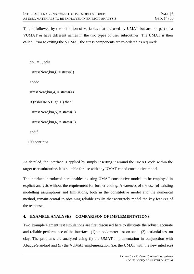
This is followed by the definition of variables that are used by UMAT but are not part of a
VUMAT or have different names in the two types of user subroutines. The UMAT is then
called. Prior to exiting the VUMAT the stress components are re-ordered as required:
do i = 1, ndir
stressNew(km,i) = stress(i)
enddo
stressNew(km,4) = stress(4)
if (nshrUMAT .gt. 1 ) then
stressNew(km,5) = stress(6)
stressNew(km,6) = stress(5)
endif
100 continue
As detailed, the interface is applied by simply inserting it around the UMAT code within the
target user subroutine. It is suitable for use with any UMAT coded constitutive model.
The interface introduced here enables existing UMAT constitutive models to be employed in
explicit analysis without the requirement for further coding. Awareness of the user of existing
modelling assumptions and limitations, both in the constitutive model and the numerical
method, remain central to obtaining reliable results that accurately model the key features of
the response.
4. EXAMPLE ANALYSES – COMPARISON OF IMPLEMENTATIONS
Two example element test simulations are first discussed here to illustrate the robust, accurate
and reliable performance of the interface: (1) an oedometer test on sand, (2) a triaxial test on
clay. The problems are analysed using (i) the UMAT implementation in conjunction with
Abaqus/Standard and (ii) the VUMAT implementation (i.e. the UMAT with the new interface)
INTERFACE ENABLING CONSTITUTIVE MODELS CODED PAGE | 7
AS USER MATERIALS TO BE EMPLOYED IN EXPLICIT ANALYSIS GEO: 14756
Centre for Offshore Foundation Systems
The University of Western Australia
in Abaqus/Explicit. The capabilities of the interface enabled constitutive formulation is then
further demonstrated through a large deformation analysis of a large diameter conical footing
penetrating into sand, carried out using the Coupled Eulerian-Lagrangian approach available in
Abaqus/Explicit.
Oedometer test
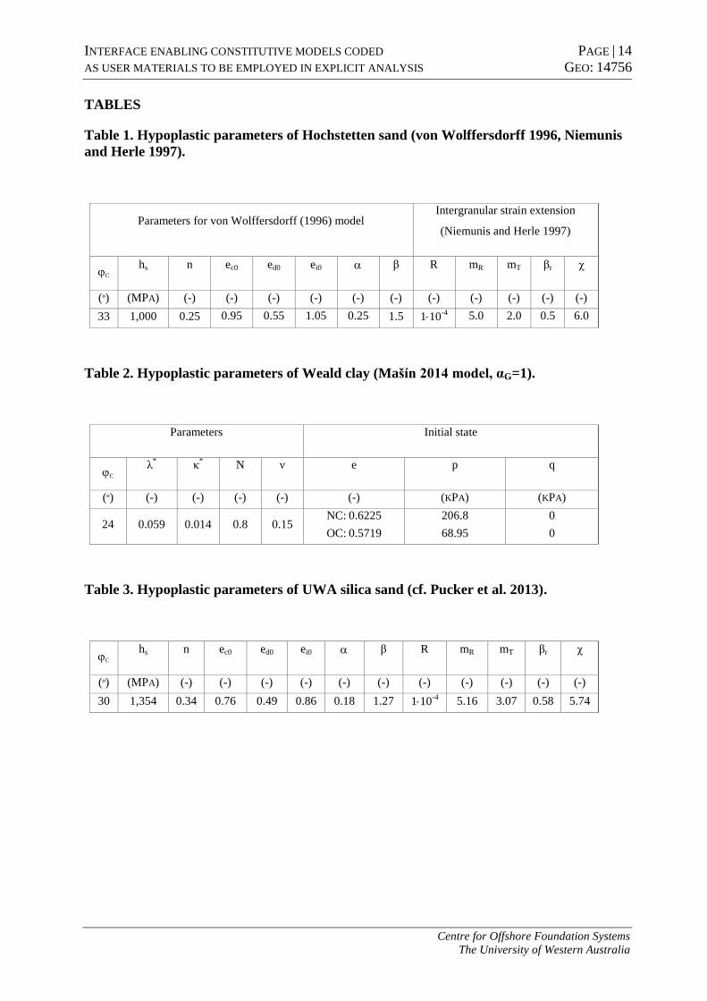
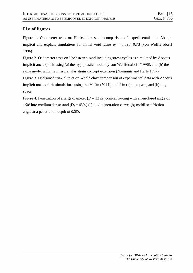
Von Wolffersdorff (1996) illustrated the capability of the hypoplastic model to reflect the
behaviour of sand of different relative densities by only varying the initial void ratio. The
general parameter set remains the same irrespective of the soil state. The hypoplastic
parameters are provided for Hochstetten sand in Table 1.
The implicit analysis performed using the UMAT routine from www.soilmodels.info produces
results (Fig. 1) that agree well with the experimental measurements and original calculated
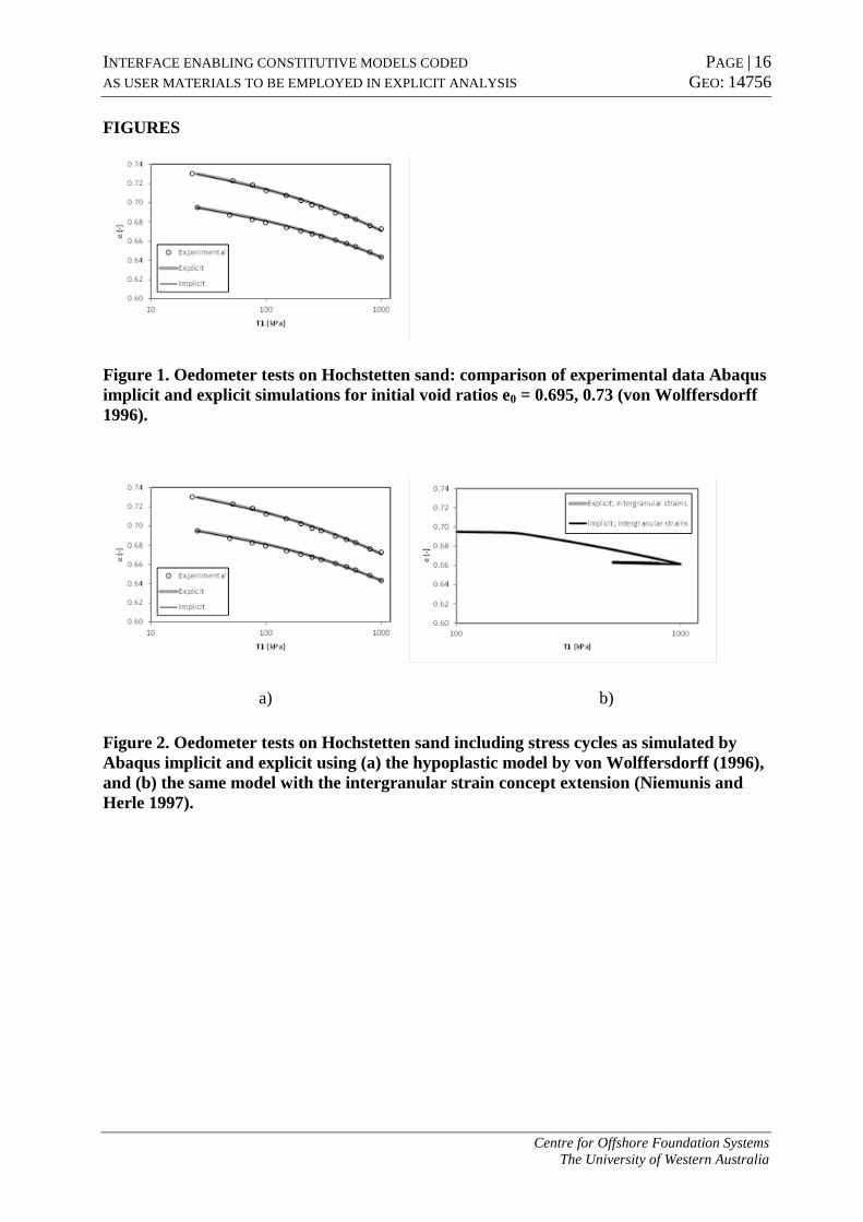
response (von Wolffersdorff 1996). The concept of intergranular strains introduced by
Niemunis and Herle (1997) is shown to reduce the excessive ratcheting (Fig. 2).
The results of the implicit and explicit analyses are indistinguishable.
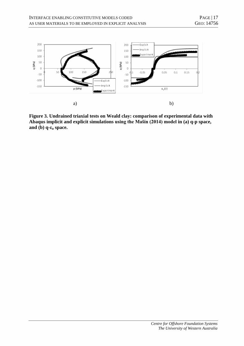
Triaxial test
The second example presents undrained triaxial tests on normally consolidated and over-
consolidated Weald clay (Parry 1960) with the hypoplastic model introduced by Mašín (2014).
Model parameters and the initial states assumed for the two analyses are provided in Table 2.
The results from implicit and explicit analyses of this study are compared with experimental
results in Figure 3. The two numerical predictions are indistinguishable, which confirms the
performance of the interface. The implicit results are further identical to those presented in
Mašín (2013), who discusses the constitutive modelling features and parameter values which
result in the differences between experimental results and numerical simulations.
These analyses confirm that the constitutive models available from www.soilmodels.info
perform as intended. They further demonstrate that:
The new interface provides a straightforward and viable approach to adapting
constitutive model user subroutines intended for implicit analysis to be employed in
explicit analysis.
The accuracy of the solution is maintained.

INTERFACE ENABLING CONSTITUTIVE MODELS CODED PAGE | 8
AS USER MATERIALS TO BE EMPLOYED IN EXPLICIT ANALYSIS GEO: 14756
Centre for Offshore Foundation Systems
The University of Western Australia
5. EXAMPLE LARGE DEFORMATION ANALYSIS WITH THE NEW USER
SUBROUTINE
Figure 4 shows the penetration resistance obtained from a large deformation analysis
performed using the Coupled Eulerian-Lagrangian approach in Abaqus/Explicit employing the
hypoplastic model for sand with the new interface. The simulation is a of a 12 m diameter
conical footing being penetrated into medium dense sand (with the parameters summarised in
Table 3) from the soil surface to a depth of approximately 4.5 m (measured from the footing
tip). This example is of a problem relevant to offshore practice, where jack-up rigs are used to
provide a platform from which to perform drilling of the seabed, facilitating the extraction of
oil and gas economically in water depths up to approximately 150 m.
Though the problem is axisymmetric, the CEL implementation in Abaqus is limited to three-
dimensional modelling with eight node elements with reduced integration the only choice for
the Eulerian part. Hence, a 90° section of the problem was analysed. Contact between Eulerian
(here: the soil) and Lagrangian (here: the footing, modelled as discretely rigid) bodies is
enforced using a general contact formulation that is based on a penalty method. Intermediate
roughness was assumed. Velocity boundary conditions were imposed that prevent vertical
movement at the base and lateral movement at the sides of the soil domain. The footing was
penetrated into the soil at a constant velocity of 1 m/s. This was selected based on
considerations of computational efficiency whilst ensuring the response remained quasi-static
(via the energy balance).
The load-penetration curve predicted in this numerical example compares well against
experimental data obtained from testing in a geotechnical centrifuge where the response is
expected to reflect that of the prototype as stress similitude is maintained. The prototype
diameter of the spudcan footing (a conical footing with a central tip, which influences the
initial part of the penetration) in these experiments was 10 m and the relative density of the
sand Dr = 37% (Bienen 2009). Hence, the response is a little softer as expected. Overall,
however, the numerical prediction agrees well with the data from physical tests, which
provides confidence in the simulation.
6. CONCLUDING REMARKS
An interface is described that enables constitutive models coded as user materials (UMAT) to
be employed in explicit analysis (VUMAT), rather than requiring coding of an entirely new

INTERFACE ENABLING CONSTITUTIVE MODELS CODED PAGE | 9
AS USER MATERIALS TO BE EMPLOYED IN EXPLICIT ANALYSIS GEO: 14756
Centre for Offshore Foundation Systems
The University of Western Australia
user routine. Reliability, robustness and accuracy of solution are demonstrated with examples
of oedometer and triaxial tests, before performance of the code is illustrated in a large
deformation explicit analysis of a footing penetrating into soil. The interface code is available
on www.soilmodels.info.
ACKNOWLEDGEMENTS
The first author is the recipient of an Australian Research Council (ARC) Postdoctoral
Fellowship (DP110101603). The work described here forms part of the activities of the Centre
for Offshore Foundation Systems (COFS), the ARC Centre of Excellence in Geotechnical
Science and Engineering, and Lloyd’s Register Foundation (LRF). LRF helps to protect life
and property by supporting engineering-related education, public engagement and the
application of research. This support is gratefully acknowledged.
INTERFACE ENABLING CONSTITUTIVE MODELS CODED PAGE | 10
AS USER MATERIALS TO BE EMPLOYED IN EXPLICIT ANALYSIS GEO: 14756
Centre for Offshore Foundation Systems
The University of Western Australia
REFERENCES
Bienen, B., Qiu, G. (2014). Numerical analysis of large penetration of a cone and a large
diameter footing into dense sand overlying clay. Proc. 14th
International Conference of the
International Association for Computer Methods and Advances in Geomechanics
(IACMAG), Kyoto, Japan.
Blecha, V., Mašín, D. (2013). Observed and calculated gravity anomalies above a tunnel driven
in clays - implication for errors in gravity interpretation. Near Surface Geophysics, Vol. 11,
No. 5, pp. 569-578.
Dafalias, Y.F., Manzari, M.T. (2004). Simple plasticity sand model accounting for fabric
change effects. Journal of Engineering Mechanics, Vol. 130, No. 6, pp. 622-634.
Dassault Systèmes. (2012). Abaqus User Subroutines Reference Manual. Providence, RI, USA.
Herle, I., Gudehus, G. (1999). Determination of parameters of a hypoplastic constitutive model
from properties of grain assemblies. Mechanics of Cohesive-Frictional Materials, Vol. 4, pp.
461-486.
Grabe, J. (1992). Experimentelle und theoretische Untersuchungen zur flächendeckenden
dynamischen Verdichtungskontrolle. PhD thesis, University of Karlsruhe, Germany.
Gudehus, G., Amorosi, A., Gens, A., Herle, I., Kolymbas, D., Mašín, D., Muir Wood, D.,
Niemunis, A., Nova, R., Pastor, M., Tamagnini, C., Viggiani, G. (2008). The
soilmodels.info project. International Journal of Numerical and Analytical Methods in
Geomechanics, Vol. 32, No. 12, pp. 1571-1572.
Hájek, V., Mašín, D., Boháč, J. (2009). Capability of constitutive models to simulate soils with
different OCR using a single set of parameters. Computers and Geotechnics, Vol. 36, No. 4,
pp. 655-664.
Henke, S., Grabe, J. (2008). Numerical investigation of soil plugging inside open-ended piles
with respect to the installation method. Acta Geotechnica, Vol. 3, No. 3, pp. 215-223.
Herle, I., Kolymbas, D. (2004). Hypoplasticity for soils with low friction angles. Computers
and Geotechnics, Vol. 31, pp. 365-373.
Hügel, H.M. (1995). Prognose von Bodenverformungen. PhD thesis, University of Karlsruhe,
Germany.

INTERFACE ENABLING CONSTITUTIVE MODELS CODED PAGE | 11
AS USER MATERIALS TO BE EMPLOYED IN EXPLICIT ANALYSIS GEO: 14756
Centre for Offshore Foundation Systems
The University of Western Australia
Liu, M.D., Carter, J.P. (2002). A structured Cam Clay model. Canadian Geotechnical Journal,
Vol. 39, pp. 1313-1332.
Mašín, D. (2005). A hypoplastic constitutive model for clays. International Journal of
Numerical and Analytical Methods in Geomechanics, Vol. 29, No. 4, pp. 311-336.
Mašín, D. (2009a). 3D modelling of a NATM tunnel in high K0 clay using two different
constitutive models. Journal of Geotechnical and Geoenvironmental Engineering (ASCE),
Vol. 135, No. 9, pp. 1326-1335.
Mašín, D. (2009b). Comparison of predictive capabilities of selected elasto-plastic and
hypoplastic models for structured clays. Soils and Foundations, Vol. 49, No. 3, pp. 381-390.
Mašín, D. (2012a). Asymptotic behaviour of granular materials. Granular Matter, Vol. 14, No.
6, pp. 759-774.
Mašín, D. (2012b). Hypoplastic Cam-clay model. Géotechnique, Vol 62, No. 6, pp. 549-553.
Mašín, D. (2013). Clay hypoplasticity with explicitly defined asymptotic states. Acta
Geotechnica, Vol. 8, No. 5, pp. 481-496.
Mašín, D. (2014). Clay hypoplasticity model including stiffness anisotropy. Géotechnique,
Vol. 64, No. 3, pp. 232-238.
Mašín, D., Tamagnini, C., Viggiani, G. and Costanzo, D. (2006). Directional response of a
reconstituted fine-grained soil - Part II: performance of different constitutive models.
International Journal for Numerical and Analytical Methods in Geomechanics, Vol. 30, No.
13, pp. 1303-1336.
Matsuoka, H., Nakai, T. (1974). Stress–deformation and strength characteristics of soil under
three different principal stresses. Proc. Japanese Soc. of Civil Engineers, Vol. 232, pp. 59-
70.
Meier, T. (2009). Application of hypoplastic and viscohypoplastic constitutive models for
geotechnical problems. PhD thesis, University of Karlsruhe, Germany.
Najser, J., Mašín, D., Boháč, J. (2012). Numerical modelling of lumpy clay landfill.
International Journal for Numerical and Analytical Methods in Geomechanics, Vol. 36, No.
1, pp. 17-35.
INTERFACE ENABLING CONSTITUTIVE MODELS CODED PAGE | 12
AS USER MATERIALS TO BE EMPLOYED IN EXPLICIT ANALYSIS GEO: 14756
Centre for Offshore Foundation Systems
The University of Western Australia
Ng, C. W. W., Boonyarak, T., Mašín, D. (2013). Three-dimensional centrifuge and numerical
modeling of the interaction between perpendicularly crossing tunnels. Canadian
Geotechnical Journal, Vol. 50, No. 9, pp. 935-946.
Niemunis, A. (2003). Extended hypoplastic models for soils. Heft 34, Schriftreihe des Instituts
für Grundbau und Bodenmechanik der Ruhr-Universität Bochum, Germany.
Niemunis, A., Grandas-Tavera, C.E., Prada-Sarmiento, L.F. (2009). Anisotropic visco-
hypoplasticity. Acta Geotechnica, Vol. 4, No. 4, pp. 293-314.
Niemunis, A., Herle, I. (1997). Hypoplastic model for cohesionless soils with elastic strain
range. Mechanics of Cohesive-Frictional Materials,Vol. 2, pp. 279-299.
Parry, R.H.G. (1960). Triaxial compression and extension tests on remoulded saturated clay.
Géotechnique, Vol.10, pp. 166-180.
Pucker, T., Grabe J. (2012). Numerical simulation of the installation process of full
displacement piles. Computers and Geotechnics, Vol. 45, pp. 93-106.
Pucker, T., Bienen, B., Henke, S. (2013). CPT based prediction of foundation penetration in
siliceous sand. Applied Ocean Research, Vol. 41, pp. 9-18, doi:10.1016/j.apor.2013.01.005.
Svoboda, T., Mašín, D., Boháč, J. (2010). Class A predictions of a NATM tunnel in stiff
clay. Computers and Geotechnics, Vol. 37, No. 6, pp. 817-825.
Qiu, G., Grabe, J. (2012). Numerical investigation of bearing capacity due to spudcan
penetration in sand overlying clay. Canadian Geotechnical Journal, Vol. 49, pp. 1393-1407.
von Wolffersdorff, P.A. (1996). A hypoplastic relation for granular materials with a predefined
limit state surface. Mechanics of Cohesive-Frictional Materials, Vol. 1, pp. 251-271.

INTERFACE ENABLING CONSTITUTIVE MODELS CODED PAGE | 13
AS USER MATERIALS TO BE EMPLOYED IN EXPLICIT ANALYSIS GEO: 14756
Centre for Offshore Foundation Systems
The University of Western Australia
List of tables
Table 1. Hypoplastic parameters of Hochstetten sand (von Wolffersdorff 1996, Niemunis and
Herle 1997).
Table 2. Hypoplastic parameters of Weald clay (Mašín 2014 model, αG=1).
Table 3. Hypoplastic parameters of UWA silica sand (cf. Pucker et al. 2013).
INTERFACE ENABLING CONSTITUTIVE MODELS CODED PAGE | 14
AS USER MATERIALS TO BE EMPLOYED IN EXPLICIT ANALYSIS GEO: 14756
Centre for Offshore Foundation Systems
The University of Western Australia
TABLES
Table 1. Hypoplastic parameters of Hochstetten sand (von Wolffersdorff 1996, Niemunis
and Herle 1997).
Parameters for von Wolffersdorff (1996) model Intergranular strain extension
(Niemunis and Herle 1997)
C hs n ec0 ed0 ei0 β R mR mT βr χ
(º) (MPA) (-) (-) (-) (-) (-) (-) (-) (-) (-) (-) (-)
33 1,000 0.25 0.95 0.55 1.05 0.25 1.5 110-4
5.0 2.0 0.5 6.0
Table 2. Hypoplastic parameters of Weald clay (Mašín 2014 model, αG=1).
Parameters Initial state
C λ
* κ
* N ν e p q
(º) (-) (-) (-) (-) (-) (KPA) (KPA)
24 0.059 0.014 0.8 0.15 NC: 0.6225
OC: 0.5719
206.8
68.95
0
0
Table 3. Hypoplastic parameters of UWA silica sand (cf. Pucker et al. 2013).
C hs n ec0 ed0 ei0 β R mR mT βr χ
(º) (MPA) (-) (-) (-) (-) (-) (-) (-) (-) (-) (-) (-)
30 1,354 0.34 0.76 0.49 0.86 0.18 1.27 110-4
5.16 3.07 0.58 5.74
INTERFACE ENABLING CONSTITUTIVE MODELS CODED PAGE | 15
AS USER MATERIALS TO BE EMPLOYED IN EXPLICIT ANALYSIS GEO: 14756
Centre for Offshore Foundation Systems
The University of Western Australia
List of figures
Figure 1. Oedometer tests on Hochstetten sand: comparison of experimental data Abaqus
implicit and explicit simulations for initial void ratios e0 = 0.695, 0.73 (von Wolffersdorff
1996).
Figure 2. Oedometer tests on Hochstetten sand including stress cycles as simulated by Abaqus
implicit and explicit using (a) the hypoplastic model by von Wolffersdorff (1996), and (b) the
same model with the intergranular strain concept extension (Niemunis and Herle 1997).
Figure 3. Undrained triaxial tests on Weald clay: comparison of experimental data with Abaqus
implicit and explicit simulations using the Mašín (2014) model in (a) q-p space, and (b) q-εa
space.
Figure 4. Penetration of a large diameter (D = 12 m) conical footing with an enclosed angle of
150º into medium dense sand (Dr = 45%) (a) load-penetration curve, (b) mobilised friction
angle at a penetration depth of 0.3D.
INTERFACE ENABLING CONSTITUTIVE MODELS CODED PAGE | 16
AS USER MATERIALS TO BE EMPLOYED IN EXPLICIT ANALYSIS GEO: 14756
Centre for Offshore Foundation Systems
The University of Western Australia
FIGURES
Figure 1. Oedometer tests on Hochstetten sand: comparison of experimental data Abaqus
implicit and explicit simulations for initial void ratios e0 = 0.695, 0.73 (von Wolffersdorff
1996).
a) b)
Figure 2. Oedometer tests on Hochstetten sand including stress cycles as simulated by
Abaqus implicit and explicit using (a) the hypoplastic model by von Wolffersdorff (1996),
and (b) the same model with the intergranular strain concept extension (Niemunis and
Herle 1997).
INTERFACE ENABLING CONSTITUTIVE MODELS CODED PAGE | 17
AS USER MATERIALS TO BE EMPLOYED IN EXPLICIT ANALYSIS GEO: 14756
Centre for Offshore Foundation Systems
The University of Western Australia
a) b)
Figure 3. Undrained triaxial tests on Weald clay: comparison of experimental data with
Abaqus implicit and explicit simulations using the Mašín (2014) model in (a) q-p space,
and (b) q-εa space.

INTERFACE ENABLING CONSTITUTIVE MODELS CODED PAGE | 18
AS USER MATERIALS TO BE EMPLOYED IN EXPLICIT ANALYSIS GEO: 14756
Centre for Offshore Foundation Systems
The University of Western Australia
a)
b)
Mobilised friction angle 40.0º
37.5 º
35.0º
32.5º
30.0º
27.5º
25.0º
22.5º
20.0º
Figure 4. Penetration of a large diameter (D = 12 m) conical footing with an enclosed
angle of 150º into medium dense sand (Dr = 45%) (a) load-penetration curve, (b)
mobilised friction angle at a penetration depth of 0.3D.