interconnection of hydromatrix units with electric power … · several lines protection device 12...
TRANSCRIPT

Interconnection of HYDROMATRIX ® units withelectric power systems
Danilovic, Hell 2006-10-18 2www.vatech-hydro.com
HYDROMATRIX®, what is it?
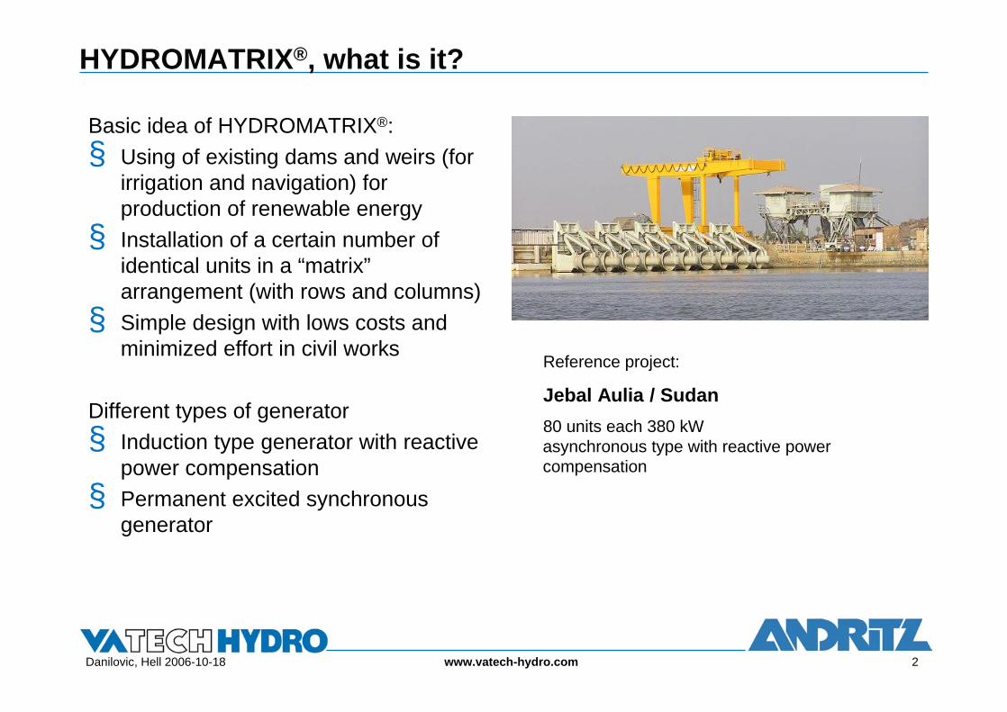
Basic idea of HYDROMATRIX®:§ Using of existing dams and weirs (for
irrigation and navigation) for production of renewable energy§ Installation of a certain number of
identical units in a “matrix” arrangement (with rows and columns)§ Simple design with lows costs and
minimized effort in civil works
Different types of generator§ Induction type generator with reactive
power compensation§ Permanent excited synchronous
generator
Reference project:
Jebal Aulia / Sudan80 units each 380 kWasynchronous type with reactive power compensation
Danilovic, Hell 2006-10-18 3www.vatech-hydro.com
The HYDROMATRIX® concept
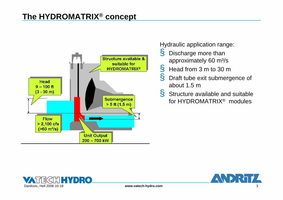
Hydraulic application range:§ Discharge more than
approximately 60 m³/s§ Head from 3 m to 30 m§ Draft tube exit submergence of
about 1.5 m§ Structure available and suitable
for HYDROMATRIX® modules
Danilovic, Hell 2006-10-18 4www.vatech-hydro.com
Components of a HYDROMATRIX® system
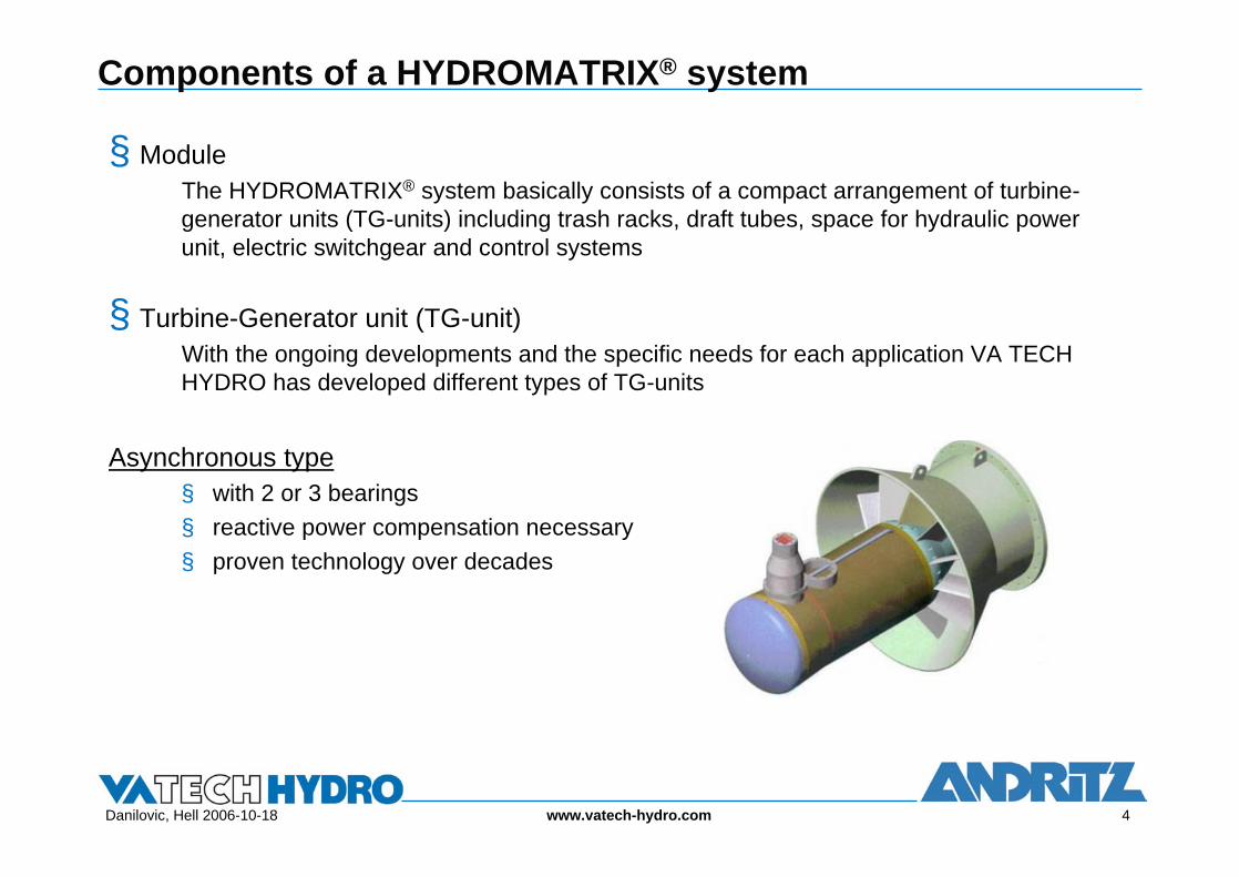
§ ModuleThe HYDROMATRIX® system basically consists of a compact arrangement of turbine-generator units (TG-units) including trash racks, draft tubes, space for hydraulic power unit, electric switchgear and control systems
§ Turbine-Generator unit (TG-unit)With the ongoing developments and the specific needs for each application VA TECH HYDRO has developed different types of TG-units
Asynchronous type§ with 2 or 3 bearings§ reactive power compensation necessary§ proven technology over decades

Danilovic, Hell 2006-10-18 5www.vatech-hydro.com
Components of a HYDROMATRIX® system – cont.
Synchronous type - StrafloMatrix™§ Rotor equipped with permanent magnets§ innovative integrated turbine runner-
generator rotor design§ reduced weight and size§ low maintenance and service requests
Special system features:§ load depended reactive power production§ induced voltage proportional to speed§ simple electrical equipment
Danilovic, Hell 2006-10-18 6www.vatech-hydro.com
StrafloMatrix™ - design features
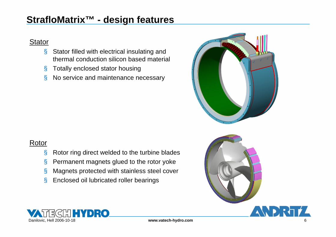
Stator§ Stator filled with electrical insulating and
thermal conduction silicon based material§ Totally enclosed stator housing§ No service and maintenance necessary
Rotor§ Rotor ring direct welded to the turbine blades§ Permanent magnets glued to the rotor yoke§ Magnets protected with stainless steel cover§ Enclosed oil lubricated roller bearings

Danilovic, Hell 2006-10-18 7www.vatech-hydro.com
StrafloMatrix™ - design features – cont.
§ Permanent magnetsMaterial Properties of Permanent Magnets
Rare earth magnets made out of Samarium-Cobalt and Neodymium-iron-boron have a very high specific energy and are therefore very well suited to be used in motors and generators
§ Corrosion Properties: Common NdFeB is highly susceptible to oxidation at the grain boundaries and will corrode easily. Additives or special manufacturing techniques such as rapid quenching can significantly enhance the corrosion properties
§ Magnetic Properties: When designing the operating point of the magnet, the negative temperature coefficient of the base materials has to be considered. The permeability of the magnets is comparable to that of air (typically µr=1.05 )
§ Thermal Properties: The demagnetization curves show that the magnetic characteristics are dependent on temperature of the permanent magnets. Exceeding a defined maximum temperature can lead to either a reversible magnetic loss or to irreversible magnetic losses

Danilovic, Hell 2006-10-18 8www.vatech-hydro.com
StrafloMatrix™ - design features – cont.
Demagnetization Curves of Permanent MagnetsThe magnetic properties of permanent magnets are shown in demagnetization curves with the temperature being the main parameter
Shapes of magnetsAs most magnets are manufactured by sintering milled powder, shapes and sizes can be chosen freely within a wide range. Size restrictions are caused by the magnetization devices and by the manufacturing process
Diagram: Demagnetization Curve of a Neodymium-iron-boron magnet material (Source: Vacuumschmelze GmbH)

Danilovic, Hell 2006-10-18 9www.vatech-hydro.com
Interconnection of HM® units with the power system
Different regulations are established worldwide to deal with interconnection requirements which energy resources have to fulfill to be connected to power systems. In some parts of world vertically integrated electricity companies managing the entire electricity supply chain: generation, transmission and distributionIn Europe, the structure of power systems has changed immensely, as a consequence of the liberalization of the electricity market, driven by EU-legislation. The European Directive defines the framework of a liberalized market. The Directive charges the Member States to appoint one or more independent transmission system operators (TSO), distribution system operators (DSO) and regulatory authorities.The final report by the CIRED Working Group on Dispersed Generation (1999) showed that variety in points put forward by questioner respondents. As a conclusion, the Working Group selected the following that generator must comply with to be considered as “distributed generator”
§ Not centrally planned§ Today not centrally dispatched§ Usually connected to the distribution network§ Smaller than 50-100MW

Danilovic, Hell 2006-10-18 10www.vatech-hydro.com
Interconnection of HM® units with the power system – cont.
These criteria were also already mentioned in the definitions of CIGRE working group WG C6.01 for Development of Dispersed Power Generation (DG).Refer to some executed projects in Austria and ongoing projects in USA and Italy, HYDROMATRIX® is designed to be connected to the distribution system considering size of individual units and the total generating output. This means that rules established for generating units of DG should apply. If we consider the most important difference between DG and classical generation that “not centrally planned or dispatched - means that the major influences such as unit commitment or reactive power generation are out of control of the system operator” HYDROMATRIX® units behave on the way which could not be strictly classified to any of generation groups.HYDROMATRIX® units’ contribution to active and reactive power generation is not controllable by the system operator but it is predictable. Taking into account that hydrology conditions are not changing unpredictably and are not fast changes as it could be a case with wind energy generation. European grid operators rules “Generators must be able to regulate their reactive power at every value between the upper and lower limits” are established differently in European countries. This means that for HYDROMATRIX® units application additional measure should be considered such as regulating power transformers or reactive power compensation.
Danilovic, Hell 2006-10-18 11www.vatech-hydro.com
Example for Implementation: Lower St. Anthony Falls/USA
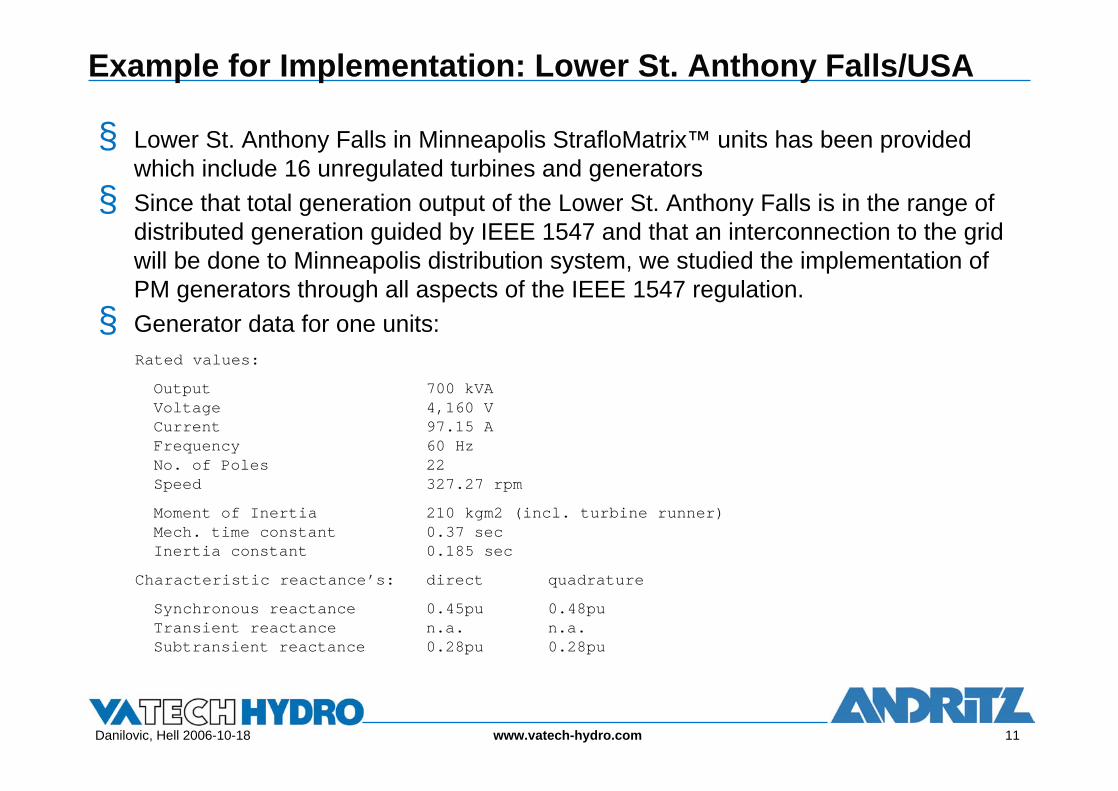
§ Lower St. Anthony Falls in Minneapolis StrafloMatrix™ units has been provided which include 16 unregulated turbines and generators§ Since that total generation output of the Lower St. Anthony Falls is in the range of
distributed generation guided by IEEE 1547 and that an interconnection to the grid will be done to Minneapolis distribution system, we studied the implementation of PM generators through all aspects of the IEEE 1547 regulation.§ Generator data for one units:
Rated values:Output 700 kVAVoltage 4,160 VCurrent 97.15 AFrequency 60 HzNo. of Poles 22Speed 327.27 rpmMoment of Inertia 210 kgm2 (incl. turbine runner)Mech. time constant 0.37 secInertia constant 0.185 sec
Characteristic reactance’s: direct quadratureSynchronous reactance 0.45pu 0.48puTransient reactance n.a. n.a.Subtransient reactance 0.28pu 0.28pu

Danilovic, Hell 2006-10-18 12www.vatech-hydro.com
Analysis of IEEE 1547 requirements
§ Single line diagram Lower St. Anthony Falls
G01
Cable 35 kV; 3 ph
G16
Cable 35 kV; 3 ph
Bus Bar 4.16 kV
Cable 2; 5 kV 2 * 3 * 1 ph
Cable 1; 13.8 kV 3 * 1 ph
PCC 13.8 kV
250 MVA12 MVA 13.8 kV / 4.16 kV
Station Service
30 kVApf = 0.85
Generators
several lines
protection device
12 MVA 4.16 kV / 13.8 kV
150 kVA 480 V / 4.16 kV

Danilovic, Hell 2006-10-18 13www.vatech-hydro.com
IEEE 1547 - Voltage Regulation
-1.0 -0.9 -0.8 -0.7 -0.6 -0.5 -0.4 -0.3 -0.2 -0.1 0.0 0.1 0.2 0.3 0.4 0.5 0.6 0.7 0.8 0.9 1.00
0.1
0.2
0.3
0.4
0.5
0.6
0.7
0.8
0.9
1
Capability Diagram
(leading pf) reactive power [p.u.](lagging pf)
activ
e po
wer
[p.u
.]
StrafloMatrix: St.Anthony Falls
voltage 90%
voltage 95%
voltage 100%
voltage 105%
voltage 110%
-1.0 -0.9 -0.8 -0.7 -0.6 -0.5 -0.4 -0.3 -0.2 -0.1 0.0 0.1 0.2 0.3 0.4 0.5 0.6 0.7 0.8 0.9 1.00
0.1
0.2
0.3
0.4
0.5
0.6
0.7
0.8
0.9
1
17 17.5 18 18.5 19 19.5 20 20.5 21 21.5 22 22.5 23 23.5 24-1
0
1
2
3
4
5
6
7
8
9
10
11
Power Flow at PCC
turbine head [ft]
pow
er [M
W,M
VAr]
StrafloMatrix: St.Anthony Falls
active power
reactive power
17 17.5 18 18.5 19 19.5 20 20.5 21 21.5 22 22.5 23 23.5 24-1
0
1
2
3
4
5
6
7
8
9
10
11
§ In general, a PM generator cannot maintain voltage at the point of common coupling (PCC) to the electric power system (EPS). § Variation of voltage at the PCC will cause a variation of the reactive energy
generated by PM generators since that reactive energy directly depends on voltage difference between the PCC voltage and generator internal voltage. This behavior of PM generators also explains how those generators could contribute to voltage regulation at the PCC.

Danilovic, Hell 2006-10-18 14www.vatech-hydro.com
§ Grounding system is design to prevent overvoltages that exceed the rating of equipment connected to the Area EPS and will not disrupt the coordination of the ground fault protection – IEEE 1547 requirement§ PM generators neutral point is isolated. Since that the 4.16 kV voltage level
is ungrounded earth fault current on this level will consist of capacitive currents flowing through capacitive resistance of all equipment connected to the 4.16 kV voltage level to ground. To avoid development of second earth fault on the different place of the 4.16 kV voltage level system a direction earth fault relay will be provided for the each individual PM generator.§ To all other voltage levels grounding methods developed by corresponding
standards will be applied.
IEEE 1547 - Integration with Area Power System Grounding

Danilovic, Hell 2006-10-18 15www.vatech-hydro.com
IEEE 1547 - Synchronization
§ The DR unit shall parallel with Area EPS without causing a voltage fluctuation at the PCC greater than ± 5% of prevailing voltage level of the Area EPS at the PCC§ StrafloMatrix™ generators shall be synchronized to the EPS using synch-check
function available in multifunctional relays of each PM generator
-70
-60
-50
-40
-30
-20
-10
0
10
0 0.2 0.4 0.6 0.8 1 1.2 1.4
phas
eang
le [d
eg]
time [secs]
Synchron ization Straflo Matrix AGONITZ File: SYN2000
phasendifference generator-grid voltage
-400
-300
-200
-100
0
100
200
300
400
500
600
0.5 1 1.5 2 2.5 3 3.5 4
pow
er [
kW,k
VAr]
time [sec]
StrafloMatrix Agonitz III file: synch0 02
active powerreactive power

Danilovic, Hell 2006-10-18 16www.vatech-hydro.com
IEEE 1547 – Load Rejection
0.6
0.8
1
1.2
1.4
1.6
1.8
2
1 2 3 4 5 6 7
frequ
ency
time [sec]
StrafloMatrix Agonitz III file: ./Juli2004/Lastabschaltung 100Pr
Emergency stop may happen in the following cases:§ Fault occurs in the EPS and causes shutdown of all StrafloMatrix™ units connected
at the time to the EPS§ Individual protection of PM generators detects a fault§ Manual shutdown of all or individual StrafloMatrix™ unit connected to the EPS due
to some detected abnormal unit operating conditions
Danilovic, Hell 2006-10-18 17www.vatech-hydro.com
IEEE 1547 – Inadvertent Energizing of the area EPS
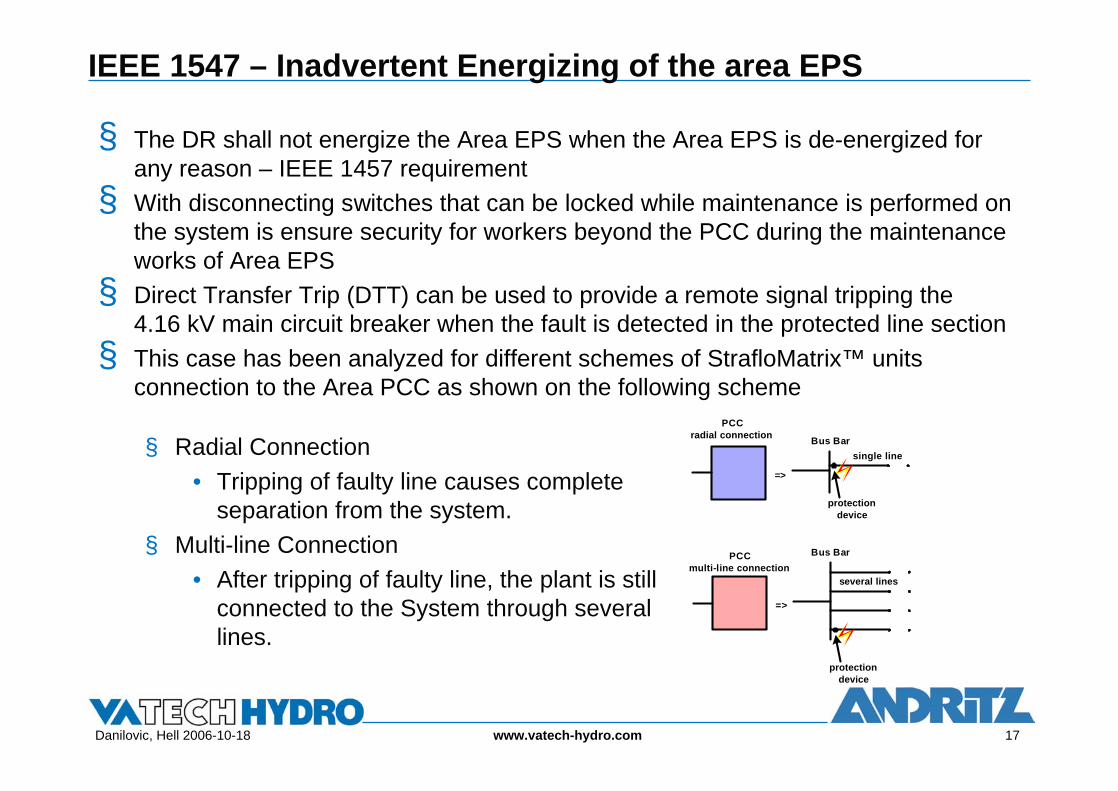
§ The DR shall not energize the Area EPS when the Area EPS is de-energized for any reason – IEEE 1457 requirement§ With disconnecting switches that can be locked while maintenance is performed on
the system is ensure security for workers beyond the PCC during the maintenance works of Area EPS§ Direct Transfer Trip (DTT) can be used to provide a remote signal tripping the
4.16 kV main circuit breaker when the fault is detected in the protected line section§ This case has been analyzed for different schemes of StrafloMatrix™ units
connection to the Area PCC as shown on the following schemePCC
radial connection
=>
Bus Barsingle line
PCC multi-line connection
=>
Bus Bar
several lines
protection device
protection device
§ Radial Connection• Tripping of faulty line causes complete
separation from the system.§ Multi-line Connection
• After tripping of faulty line, the plant is still connected to the System through several lines.

Danilovic, Hell 2006-10-18 18www.vatech-hydro.com
IEEE 1547 – 3 phase Fault PCC Radial Connection
Blue: 16 turbines atmaximum head
Red: 1 turbine at minimum head
Danilovic, Hell 2006-10-18 19www.vatech-hydro.com
IEEE 1547 – 1 phase Fault PCC Radial/Multi-line Connection
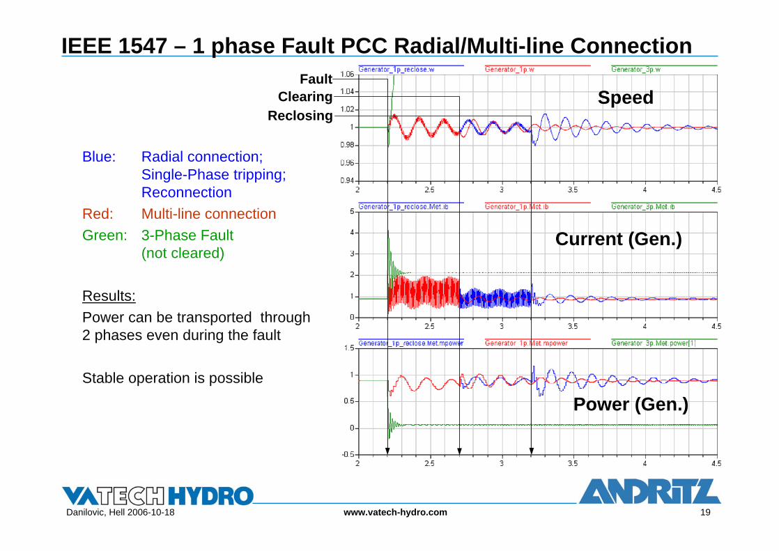
Blue: Radial connection;Single-Phase tripping;Reconnection
Red: Multi-line connectionGreen: 3-Phase Fault
(not cleared)
Results:Power can be transported through 2 phases even during the fault
Stable operation is possible
FaultClearing Speed
Current (Gen.)
Power (Gen.)
Reclosing
Danilovic, Hell 2006-10-18 20www.vatech-hydro.com
IEEE 1547 – Response to Area EPS Abnormal Frequency
Sun May 8 10:00:26 2005
56 57 58 59 60 61 62 63 641
2
3
4
5
6
7
8
9
10
11
12
13
14
15
16
Active Power at PCC [MW]
frequency [Hz]
No. o
f uni
t in
oper
atio
n
StrafloMatrix: St.Anthony Falls grid voltage = 100%
1 1
2 2
3 3
4 4
55
66
77
88
99
10
56 57 58 59 60 61 62 63 641
2
3
4
5
6
7
8
9
10
11
12
13
14
15
16
Sun May 8 10:00:26 2005
56 57 58 59 60 61 62 63 641
2
3
4
5
6
7
8
9
10
11
12
13
14
15
16
Reactive Power at PCC [MVAr]
frequency [Hz]
No. o
f uni
t in
oper
atio
n
StrafloMatrix: St.Anthony Falls grid voltage = 100%
-1.4
-1.2
-1
-1
-0.8
-0.8
-0.8
-0.6
-0.6
-0.6
-0.4
-0.4
-0.4
-0.2
-0.2
-0.2
-0.2
0
0
0
0
0.2
0.2
0.2
0.2
0.4
0.4
0.4
0.6
0.6
0.8
1
1.2
56 57 58 59 60 61 62 63 641
2
3
4
5
6
7
8
9
10
11
12
13
14
15
16
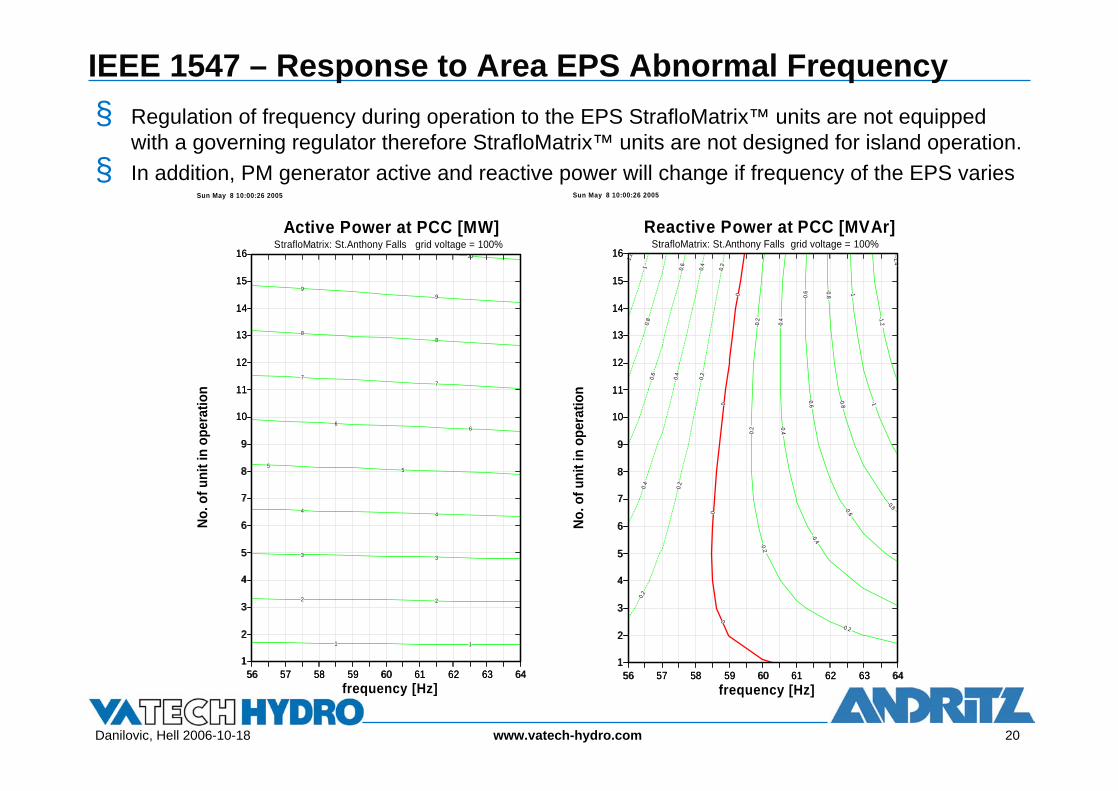
§ Regulation of frequency during operation to the EPS StrafloMatrix™ units are not equipped with a governing regulator therefore StrafloMatrix™ units are not designed for island operation.
§ In addition, PM generator active and reactive power will change if frequency of the EPS varies

Danilovic, Hell 2006-10-18 21www.vatech-hydro.com
IEEE 1547 – Response to Area EPS Abnormal Conditions: Limitation of Flicker Induced by the DR
0
100
200
300
400
500
600
700
0 2 4 6 8 10
powe
r [k
W,k
VAr]
time [sec]
StrafloMatrix Agonitz III file: ./Juli2004/Last100Pr
active powerreactive power
§ Taking the possible operation regime of StrafloMatrix units into account, we have assumed 1 or 2 start/stops per day. The allowable percentage voltage DIP for this scenario according to the Xcel Energy´s regulations is 4%. The StrafloMatrix™ units will fulfill this requirement§ Step changes of the StrafloMatrix™ unit output are not possible (unregulated units)
105
106
107
108
109
110
111
112
113
114
115
1 2 3 4 5 6 7 8 9 10
gene
rato
r cur
rent
[A]
time [sec]
StrafloMatrix Agonitz III file: ./Juli2004/Last100Pr
abs. current
Danilovic, Hell 2006-10-18 22www.vatech-hydro.com
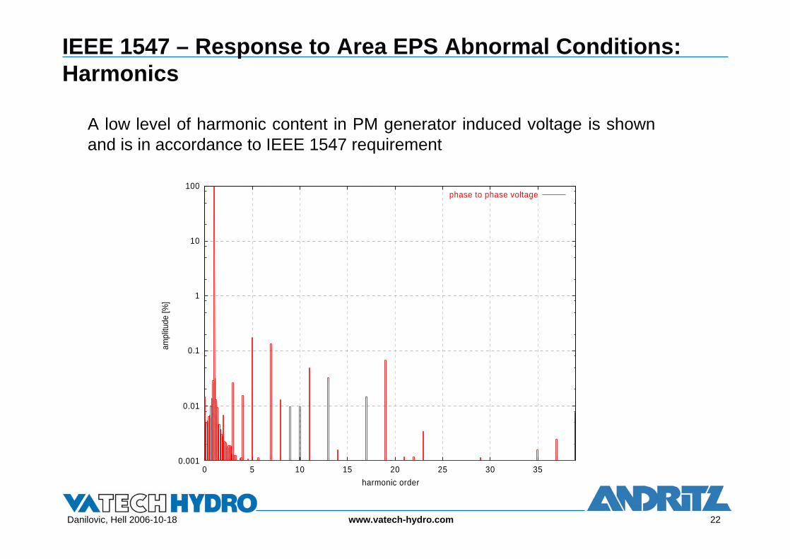
IEEE 1547 – Response to Area EPS Abnormal Conditions: Harmonics
A low level of harmonic content in PM generator induced voltage is shown and is in accordance to IEEE 1547 requirement
0.001
0.01
0.1
1
10
100
0 5 10 15 20 25 30 35
ampl
itude
[%]
harmonic order
phase to phase voltage
Danilovic, Hell 2006-10-18 23www.vatech-hydro.com
IEEE 1547 – other requirements
§ Monitoring ProvisionsAny request either from IEEE 1547 or some local utility organization regarding provisions for monitoring DR unit connection status
§ Isolation Device Readily accessible, lockable, visible-break isolation device located between the Area EPS and DR unit
§ Protection from Electromagnetic InterferenceThe multifunction protection relays planned to be used for this project will fulfill condition referring to protection from Electromagnetic Interference as specified in IEEE 1547 requirement
§ Surge Withstand PerformanceSwitching over voltages at the 4.16 kV equipment can not be analyzed accurately with a simple model. Nevertheless the investigations showed that over voltages at the StrafloMatrix™ generator after opening of the generator contactor are likely to have the highest values
§ Paralleling DeviceThe interconnection system paralleling-device shall be capable of withstanding 220% of the interconnection system rated voltage, IEEE 1547 requirement

Danilovic, Hell 2006-10-18 24www.vatech-hydro.com
IEEE 1547 – other requirements
§ Response to Area EPS Abnormal Conditions: Area EPS FaultsThe Lower St. Anthony Falls DR equipment is designed considering that “the combined available fault current” on the 13.8 kV voltage level will be 250 MVA as defined in standards for this voltage level
§ Response to Area EPS Abnormal Conditions: Area EPS Reclosing CoordinationIn accordance with IEEE requirements the Lower St. Anthony Falls units will be disconnected from the EPS as soon as a temporary fault condition occurs in the Area EPS
§ Response to Area EPS Abnormal Conditions: Loss of SynchronismAny separation from the main section of the Area EPS will bring units to a shutdown position. Reconnection to the Area EPS will be done as outlined in the chapter Synchronization

Danilovic, Hell 2006-10-18 25www.vatech-hydro.com
References
/1/ www.hydromatrix.at/2/ VA TECH HYDRO: HYDROMATRIX®– Product Information/3/ Volker Kienberger-, Harald Schmid, VA TECH HYDRO GmbH & Co, Austria and
Hans Schimpf, VERBUND-Austrian Hydro Power AG, Austria, Hydro Vision 2006, Portland USA
/4/ William D. Stevenson, Jr. Element of Power System Analyses/5/ Prabha Kundur, Power System Stability and Control, McGraw Hill 1994/6/ Univ.-Prof.Dr.-Ing Guenther Brauner, DI Martin Heidl, Vienna University of
Technology: Grid Integration of StrafloMatrix™ - Generators (Lower St. Anthony Falls)
/7/ Cigre, July 2003 : Development of Dispersed generation and Consequences for Power System
/8/ CIRED; Report of Working Group No. 4 on Dispersed generation/9/ MIT Open Courseware ocw.mit.edu/10/ IEEE standard 1547: Standard for Interconnecting Distributed Resources with
Electric Power Systems

Danilovic, Hell 2006-10-18 26www.vatech-hydro.com
Authors
§ Nesha Danilovic, DI, is a member of Engineering Services of VA TECH HYDRO GmbH, Vienna, Austria. Graduated at the ElectrotechnicalUniversity of Belgrade he works about 20 years as a consultant in a field of hydro power plant design in Serbia and Canada before he joined VA TECH HYDRO in 1999. He is also registered Professional Engineer in Canada.mailto:[email protected]
§ Johann Hell, DI, is a member of Generator Hydro Engineering Tenders of VA TECH HYDRO GmbH, Vienna, Austria. Graduated at the Vienna University of Technology he works about 15 years in the field of Sales and R&D for variable speed drives and frequency converters. Since 1999 he is project engineer for generator tenders.mailto:[email protected]