interactive multi-objective path planning through a …mike/mikeg/papers/spie_9837...interactive...
TRANSCRIPT

Interactive multi-objective path planning through apalette-based user interface
Meher T. Shaikh, Michael A. Goodrich, Daqing Yi, and Joseph Hoehne
Brigham Young University, Provo, UT, USA
ABSTRACT
In a problem where a human uses supervisory control to manage robot path-planning, there are times whenhuman does the path planning, and if satisfied commits those paths to be executed by the robot, and the robotexecutes that plan. In planning a path, the robot often uses an optimization algorithm that maximizes orminimizes an objective. When a human is assigned the task of path planning for robot, the human may careabout multiple objectives. This work proposes a graphical user interface (GUI) designed for interactive robotpath-planning when an operator may prefer one objective over others or care about how multiple objectives aretraded off. The GUI represents multiple objectives using the metaphor of an artist’s palette. A distinct color isused to represent each objective, and tradeoffs among objectives are balanced in a manner that an artist mixescolors to get the desired shade of color. Thus, human intent is analogous to the artist’s shade of color. We callthe GUI an “Adverb Palette” where the word “Adverb” represents a specific type of objective for the path, suchas the adverbs “quickly” and “safely” in the commands: “travel the path quickly”, “make the journey safely”.The novel interactive interface provides the user an opportunity to evaluate various alternatives (that tradeoffbetween different objectives) by allowing her to visualize the instantaneous outcomes that result from her actionson the interface. In addition to assisting analysis of various solutions given by an optimization algorithm, thepalette has additional feature of allowing the user to define and visualize her own paths, by means of waypoints(guiding locations) thereby spanning variety for planning. The goal of the Adverb Palette is thus to provide away for the user and robot to find an acceptable solution even though they use very different representations ofthe problem. Subjective evaluations suggest that even non-experts in robotics can carry out the planning taskswith a great deal of flexibility using the adverb palette.
Keywords: human-robot interaction, multi-objective decision making, user interface, supervisory control
1. INTRODUCTION
Consider a problem where a human uses supervisory control to manage robot path-planning by evaluatingmultiple paths generated by an algorithm and assigning a robot to execute one of the paths. Given a set ofpaths, the task of choosing among these multiple paths places a burden on a human operator, as the humanmay find it difficult to compare the paths against each other. This triggers the need of a robust and intuitiveinterface that can act on the output of well established path-planning algorithms, and allow the user to selectthe most desired path in a way that keeps human workload within acceptable bounds.
This paper proposes a novel human-robot interface called as an Adverb Palette (AP) to help the operatorissue commands to the robot to take a specific path from the many available paths. Figure 1 shows the adverbpalette. On the left side of the interface, the map shows in gray all potential paths that a robot can take, andthe right side of the interface provides an area that can be used by the human to find tradeoffs among the paths.Based on the command issued on right side panel, one of the gray paths gets highlighted on the left panel.
An adverb encodes the objective associated by a verbal command given by the human to the robot. Forexample consider a command, “Go from point A to point B quickly.” The adverb “quickly” in the commandindicates minimizing path length, in other words asking the robot to take the shortest path from point A topoint B. For a command, “Go from point A to point B quickly and safely,” two objectives need to be minimized:path length and risk of being exposed to threats in the environment, respectively. AP is an interface where suchcommands can be interactively evaluated by a user. The execution of the command by the robot, and robot’sperformance evaluation is not in the scope of this work and is left for future work. The goal of this paper is topresent th adverb palette interface and subjectively compare it to two other interfaces.
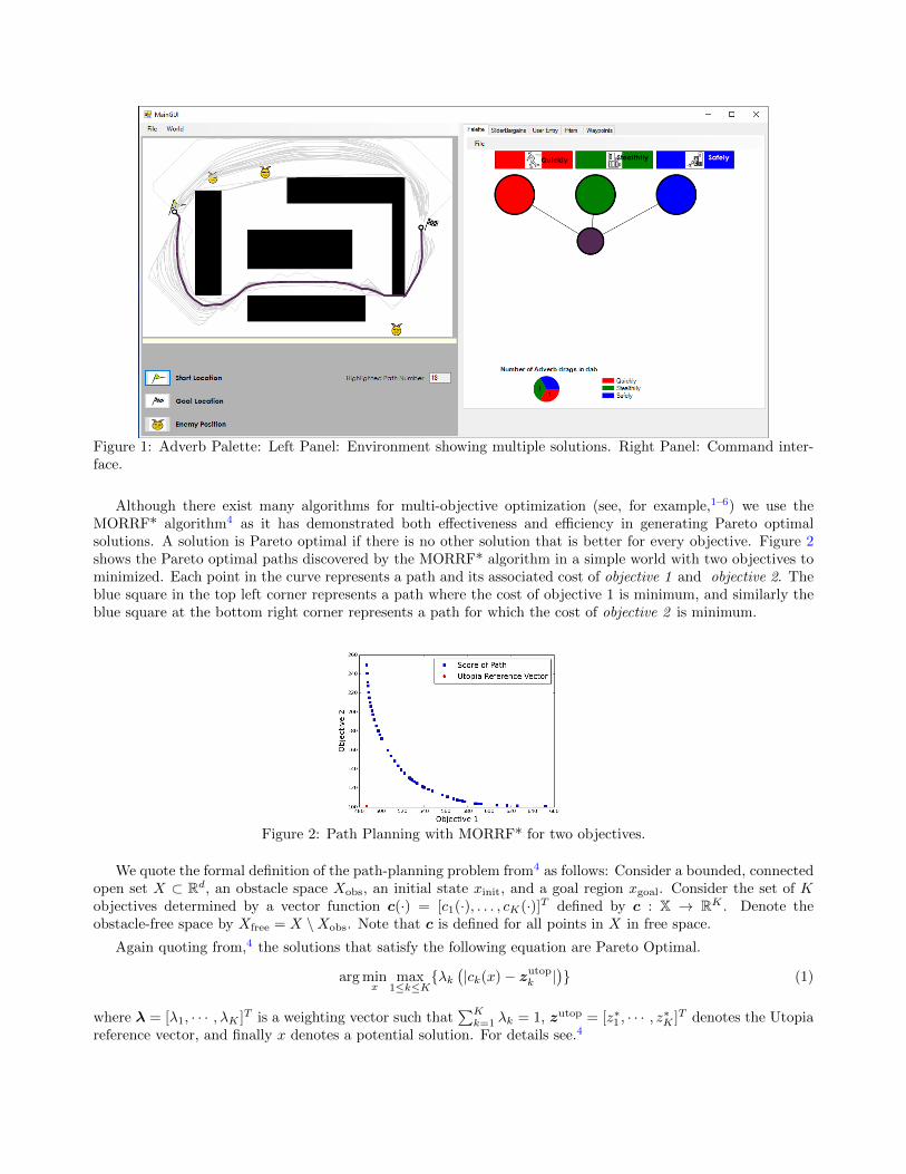
Figure 1: Adverb Palette: Left Panel: Environment showing multiple solutions. Right Panel: Command inter-face.
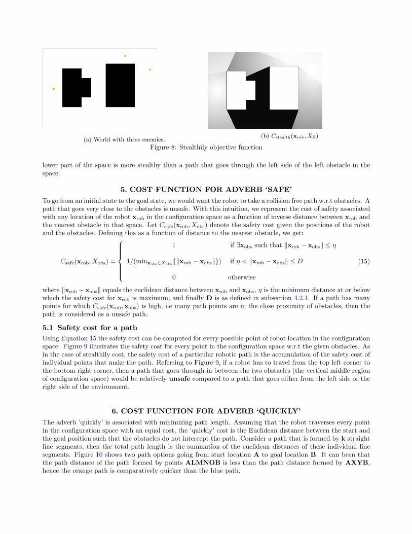
Although there exist many algorithms for multi-objective optimization (see, for example,1–6) we use theMORRF* algorithm4 as it has demonstrated both effectiveness and efficiency in generating Pareto optimalsolutions. A solution is Pareto optimal if there is no other solution that is better for every objective. Figure 2shows the Pareto optimal paths discovered by the MORRF* algorithm in a simple world with two objectives tominimized. Each point in the curve represents a path and its associated cost of objective 1 and objective 2. Theblue square in the top left corner represents a path where the cost of objective 1 is minimum, and similarly theblue square at the bottom right corner represents a path for which the cost of objective 2 is minimum.
Figure 2: Path Planning with MORRF* for two objectives.
We quote the formal definition of the path-planning problem from4 as follows: Consider a bounded, connectedopen set X ⊂ Rd, an obstacle space Xobs, an initial state xinit, and a goal region xgoal. Consider the set of Kobjectives determined by a vector function c(·) = [c1(·), . . . , cK(·)]T defined by c : X → RK . Denote theobstacle-free space by Xfree = X \Xobs. Note that c is defined for all points in X in free space.
Again quoting from,4 the solutions that satisfy the following equation are Pareto Optimal.
arg minx
max1≤k≤K
{λk(|ck(x)− zutopk |
)} (1)
where λ = [λ1, · · · , λK ]T is a weighting vector such that∑K
k=1 λk = 1, zutop = [z∗1 , · · · , z∗K ]T denotes the Utopiareference vector, and finally x denotes a potential solution. For details see.4

Given the Pareto optimal solution set that satisfy Equation 1, where each solution represents a path thatgoes from point A to point B, the goal is to enable a user to find a tradeoff that best expresses his or her intent.Expressing intent has two subproblems to be solved:
1. Design an interface to construe human intent, and,
2. Design an algorithm that translates from the interface input to one of the Pareto optimal paths that mostclosely matches human intent.
2. RELATED WORK
The design and use of Adverb Palette (AP) relates to user interface design, multi-criterion/attribute/objectivedecision making, human-machine systems, human-factors, human-robot interaction, ecological interface design,cognitive engineering systems etc.
Making trade-offs in decision-making is known as multiple criterion decision-making,7 multiple attributedecision-making,8 etc. The goal however remains the same as to make preference decisions over available alter-natives, or in other words, to choose from among a finite set of discrete alternatives.9 This paper uses threeobjectives: minimizing distance from the robot’s start location to a goal location, avoiding exposure of the robotto one or more enemies, and avoiding collisions with obstacles.
A great deal of emphasis has been on designing powerful and easy to use interfaces.10–17 Many in the field alsoelaborate on the challenges and complexity of practical design problems. The AP is closely related to ecologicalinterface design,11 which is based on a taxonomy of skills, rules, and knowledge used in cognitive control.18 Anecological interface should not contribute to the difficulty of task, and at the same time it should support theentire range of activities that the operators are faced with. The term ecological (relation between organismand the the environment) corresponds to the operator and the work environment. In our scenario, the workenvironment is the n-dimensional space that the robot is going to navigate from one location to another, andthe AP is at the disposal of an operator to make effective path planning decision. To make the robotic-pathplanning task easier and intuitive for the operator, we have used the metaphor of a palette. In the current work,the three objectives that we consider are represented by the colors red, green and blue respectively. Colors area strong stimuli,19 though the interfaces in this paper would not work for color blind individuals.
Although teams of humans and robots working as peers may be forthcoming, most robots are managed usingsupervisory control.20 For example, in search and rescue operation where the robot may be in unstructured andunfamiliar environments,14,21 strategic decision-making may be necessarily performed by an operator. Designinginterfaces for supervisory control is one element of the field of human-robot interaction (HRI ).22 Designingintuitive and efficient interfaces has been a challenging issue in HRI.23,24 However, significant research on HRIis inspired by the principles, and levels of autonomy (LOA) given by.25 According to types and levels ofhuman interaction,25 a design involving human-machine interaction varies according to level of automationrequired. Studies has also been conducted in adjusting the autonomy responding to the environment and workloadchanges.26 Considering the given LOA, AP allows the user to make decisions on paths, and then delegate thetask to the robot. Note that recent work has identified a critical need to move past the limitations of LOAs onhuman-robot teaming.27
As previously mentioned, robots are transitioning from functional tools to interactive teammates.28–31 Robustlevel of robot intelligence will cause HRI to evolve beyond command and control methods. Human mentalmodels30,31 for human-robot teams dictate how humans expect a robot to plan and execute tactical movementcommands under constraints like “navigate quickly”, “navigate stealthily”, and “navigate safely”. AP providesa medium to explicitly express the human expectations on the interface with the help of adverbs in order to planthe path for robot.

3. ADVERB PALETTE
The Adverb Palette (AP) is a mouse-based interactive graphical user interface designed for motion-planning forrobots. It provides selection and visualization of possible routes/paths that a robot can take to go from a startlocation xinit to a goal region xgoal, given the configuration space. The AP interface helps the user to blendobjectives in a way a painter blends colors on a palette. A blend/mixture of objectives corresponds to one pathfrom the available Pareto optimal paths. As shown in Figure 1, the Adverb Palette has two parts: the map inthe left panel that aids visualization and the command interface (CI) in the right panel through which the usercan balance different adverbs. In short, the right panel is the command area for the user actions, and the mapis the area that gets updated by highlighting the path according to the user’s action on the CI. We will exploretwo types of AP interfaces.
Consider an AP interface that supports three adverbs: Quickly, Stealthily, and Safely, symbolized by colorsred, green and blue, respectively on the CI.
• Quickly: A command to the robot to consider a path which has shortest distance.
• Stealthily: A command to the robot to consider a path that avoids being viewed by enemies.
• Safely: A command to the robot to consider a path that stays away from obstacles.
We have developed the adverb palette and a complementary interface that uses a different CI which we callthe sliders interface. We have also implemented a baseline command interface waypoints input. The map iscommon to all these options. In each case, the map shows all the routes (paths) in gray, and with no user actiona highlighted path is displayed that gives equal preference to all the adverbs. Each of the options has a differentway of balancing the adverbs for a particular tradeoff path. The following sections briefly describe each option.
3.1 Palette
The palette AP displays three initial circles called the “primary dabs,” one for each adverb (objectives). The usercan select a path that uses only one objective by clicking on one of the primary dabs; i.e. to take the shortestpath, most stealthy path, or most safe path by clicking quickly, stealthily, or safely, respectively. The user canalso issue a mixture of the above adverbs by dragging and dropping adverbs into the white area of the CI tocreate smaller circles called “paint dab” that blend colors, similar to the way a painter mixes the colors in herpaint dab to get a desired shade. Line segments connect the primary and paint dabs, creating a tree structurethat allows the human to see the proportions of each objective.
For example, the user can command a robot to go from location A to location B using a path that is bothquick and stealthy, which is represented numerically as “ 50% quickly, 50% stealthily, 0% safely ”. This numericalmixture can be made by dragging the adverb quickly into a new paint dab, and later on dragging the adverbStealthily onto it. Blending in multiple adverbs (colors) is thus equivalent to making trade-offs with multipleobjectives. The default magenta paint dab in Figure 1 is thus an example of a mixture “ 33.33% quickly, 33.33%stealthily, 33.33% safely”. Such a mixture may be desired if there is a command for the robot to move fromlocation A to B such that it should move fast, should stay away from both obstacles and the enemy.
The pie graph on the lower left area in the CI shows the proportion of each objective in a particular paintdab. The paint dab thus represents a human command. By mixing different paint dabs, a user can visualize theconsequences of different commands. Figure 3 shows an example command where the user desires a path that isquick and safe but does not care about being seen by enemies.
We now discuss the algorithm used to translate the user commands into a tradeoff between objectives. LetK denote the number of objectives and let the user’s action be denoted by x. The CI highlights the paths onthe map for each potential solution x. Let dabd represent any paint dab on CI. Let ni be the number of timesthe user has dragged adverb i on dabd, where 0 > i ≤ K. The total number of drags a user makes for dabd is:
n =
K∑i=1
ni (2)

Figure 3: Quick and safe command: lowermost dab in CI represents the command, and the map shows thecorresponding path (highlighted magenta)
Based on the number of adverb drags the user makes on the paint dab, the user’s intent, also referred to ashuman intent, can be represented as a vector ~hn as:
~hn = [h1n , h2n , ..., hKn]T (3)
where hin is computed as ni/n. Therefore,∑K
i=1 hin = 1.
In Section 7, we will discuss the mapping between the human intent and the path that best matches theintent.
3.2 Sliders
Figure 4 shows the slider interface of the CI. Here the user adjusts the trackbars to get to a desired mixture, andthe corresponding path from the left panel is selected. The three sliders represent the three adverbs. The usercan issue any of the three primary commands to the robot i.e. to take the shortest path, most stealthy path, ormost safe path by sliding the red, green, or blue slider to the maximum units, respectively.
If maxscale is the maximum number of units considered for each slider, then at any point of time, the sumof the units on each slider do not exceed the value maxscale. Therefore, if maxscale is 100, and if the red, green,or blue sliders are at say 33, 33, 34 units respectively, then moving the blue slider to 60 units will cause a changeto the slider units to 20, 20, 60 units respectively. The adjustment thus guarantees that at any point of time themixture represents a percentage of each of the adverbs. Unlike the palette, the user can discover paths whilemoving a slider, and settle down to certain position if she desires it; if the user moves one slider the other twosliders get updated automatically and the corresponding path gets shown on the map.
Let si is the number of units on slider i , and let maxscale be the maximum number of units considered foreach slider. The maximum units are determined by the objective values for the set of paths returned by theMORRF* algorithm; the maximum unit is the cheapest path for that objective returned by MORRF* and theminimum unit is the most expensive path returned by MORRF*. The human intent can be represented as avector ~hs as:
~hs = [h1s , h2s , · · · , hKs]T (4)
where his is computed as si/maxscale. Therefore,∑K
i=1 his = 1.
Let M(H,K) represent a matrix of slider values such that:

Figure 4: Adverb Palette: Slider interface.
• each row represents slider values, a unique combination of K-slider values treated as a vector ~s
• each element in a row represents a slider value, where the slider value si is si ∈ Z : 0 ≤ si ≤ maxscale.
• the elements in each row add to the value maxscale
• H is the total number of rows in the matrix, where each row represents a unique combination of the Kslider values (in other words there are H combinations), and
• K is the number of columns in the matrix. Each column represents one objective/slider.
In Section 7, we will discuss the mapping between the human intent and the path that best matches theintent.
3.3 Waypoints
The waypoints interface assists a user to construct her own path on the map by allowing her to provide locationguidelines that the robot should visit while taking a path. Unlike the other two interfaces, the user here doesnot make a tradeoff among the available paths from the algorithm but instead makes her own path on the map.She can however compare her path with the best or worst with respect to an adverb based on the Pareto optimalpaths’ best and worst for that particular adverb. Figure 5 shows one of the paths constructed using the waypointsinterface.
The interface allows to point to locations using ‘Submit Waypoints’ button. Then when the user is donesubmitting the main location points that she desire, she can commit these locations to form a path using‘Commit Waypoints’ button. Any number of paths can be created using the mentioned button pair. Clicking ona paths’ waypoint will give its corresponding path score. All paths can be cleared off to remove mess using ‘ClearWaypoints’ button. The path score is calculated in a way similar to how the MORRF* algorithm calculates thescore for each adverb for a path.
The following sections detail the approach towards finding the costs associated with paths generated by thecomputer algorithm, and the one generated by the waypoints interface.

Figure 5: Waypoints Interface
4. COST FUNCTION FOR ADVERB ‘STEALTHILY’
In the introduction, we discussed in brief the adverb ‘stealthily’. Choosing a path that is stealthy means taking apath that is less likely to be detected or seen by the enemies that are posted in the region of interest. Therefore,we express the cost function in terms of the probability of the path being seen by enemy.
Let XE be the set of the locations of n enemies, XE = {xei |xei ∈ Xfree}, and let the location of the robot bedenoted by xrob. We define the cost of stealthiness for any location of the robot xrob ∈ Xfree, in terms of theprobability of this point being seen. Let Cstealth(xrob, XE) denote the stealthily cost given the positions of therobots and the enemies. Defining this as the probability of being seen by any enemy gives:
Cstealth(xrob, XE) = PSeen(true). (5)
Equation 5 defines the cost in terms of the probability that the robot is seen by at least one enemy. We willnow create a Bayesian network that allows us to compute PSeen(true). Formally, we say that the agent has beenseen if it has been seen by one or more enemies. Thus, we have a family of boolean random variables Seeni, onefor each enemy, and the Seen random variable is an accumulation of these.
This means that we will compute PSeen(true) as the marginal distribution from the joint probability of allrandom variables as follows:
PSeen(true) =∑
s1,...,sn
PSeen,Seen1,...Seen2(true, s1, . . . , sn). (6)
We now construct the Bayesian network by which this joint probability will be computed. We adopt a NoisyOR network because it matches our intention that the robot is seen if it is seen by any enemy [32, Chapter 14].
Computing the joint distribution will be done in two steps: First, we propose a simple Boolean network thatmodels how the Seen random variable relates to the set of Seen by enemy i random variables. Second, we proposea second simple Boolean network that models how the Seen by enemy i random variable can be created fromcomponent parts.

Figure 6: Probability of xrob being seen by any enemy (modelled by Noisy OR).
4.1 Seen by Any Enemy
Figure 6 illustrates a Bayesian network that models the probability of being seen as a function by any of theenemies. The Bayesian network uses a Noisy OR model. In the Noisy OR model, we construct a conditionalprobability table for PSeen|Seeni,···Seenn
(true|s1, · · · , sn) for each si ∈ {true, false}.The algorithm for constructing this table assigns the probability of n + 1 rows in the table, computing the
probability of every other row from these initial assignments. The rows that are assigned values correspond tosituations where one and only one enemy, say enemy number i, sees the robot and all other fail to see the robot.This means that values are assigned for
PSeen|Seen1,...Seenn(true|false, . . . , false, true, false, . . . , false) = pi (7)
where the true on the right side of the conditioning bar occurs at the position corresponding to random vari-able Seeni. For example, Table 1 shows an example conditional probability table when there are 3 enemies inthe environment. As illustrated in the figure, when there are n enemies then we need to specify n values.
Seen1 Seen2 Seen3 piT F F p1F T F p2F F T p3F T T 1− [(1− p2)× (1− p3)]
Table 1: Conditional Probability Table for three enemies: T=true F=false.
By convention, the probability of the Seen random variable being true given that all of its parent randomvariables are false is zero. Values at other positions are assigned as follows:
PSeen|Seen1,··· ,Seenn(true | s1, · · · , sn) = 1−
∏{i:si=true}
(1− pi) (8)
where the pi is defined in Equation 7. The last row of Table 1 illustrates this situation.
Equations 7-8 define a noisy-OR in terms of tunable parameters pi. For simplicity, we let pi = 1 for all i. Inthe context of the cost associated with the “stealthily” adverb, this produces the effect of saying that there is anequal cost to the robot if one, two, or more enemies see the robot. Formally, when ∀ipi = 1 implies that
PSeen|Seen1,...Seenn(true|s1, . . . , sn) =
{1 if any si =true0 otherwise
(9)
Equation 9 leads to a convenient form for computing the marginal probability PSeen,

PSeen(true) =∑
s1,··· ,sn
PSeen,Seen1,···Seenn(true | s1, · · · , sn)
=∑
s1,··· ,sn
PSeen|Seen1,··· ,Seenn(true | s1, · · · , sn)
n∏i=1
PSeeni(si)
=
[ ∑s1,··· ,sn
n∏i=1
PSeeni(si)
]−
n∏i=1
PSeeni(false),
(10)
where the first line is how you compute a marginal distribution from a joint distribution, the second line exploitsthe conditional independence assumptions of the noisy-OR Bayesian network, and the last line follows from thefact that the conditional is only one or zero.
4.2 Detection Likelihood of a robot by an enemy ei
Consider three factors that affect whether the robot at location xrob can be seen by an enemy: the distanceof xrob to xei encoded as detection range, the visibility of xrob from xei considering objects in the world, andvisibility of xrob from xei considering the environment as terrain. The resulting effect after considering all thethree factors for an individual enemy yields detection likelihood of xrob by xei . This detection likelihood servesas the PSeeni , i.e. the probability of xrob being detected or seen by xei . The factors contributing to this detectionlikelihood are computed as follows:
4.2.1 Detection range
A distant enemy is less likely to have an harmful effect at xrob than an enemy that is standing next to it. Thisaspect is captured in detection range as PdRangei(Seeni;xrob,xe) which is calculated as a function of euclideandistance between the xrob and xe, ‖xrob − xe‖, in d-dimensional space, where xrob 6= xe.
PdRangei(Seeni;xrob,xe) =
1 if 0 ≤ ‖xrob − xe‖ ≤ δm(‖xrob − xe‖) + b if δ < ‖xrob − xe‖ ≤ D
0 otherwise(11)
where δ is the minimum distance at or below which the detection of xrob by xe is maximum, hence 1, and Dis the maximum possible distance between two points across the configuration space. As ‖xrob − xe‖ reachesD, the likelihood of detection approaches zero. Therefore, given this definite detection range, the probability ofdetection for any distance that lie between δ and D follows the equation of line formed between points (δ, 1) and(D, 0) with O as origin, m representing its slope, and b being the y-intercept . Figure 7 illustrates the detectionrange curve.
4.2.2 Visibility
Two points in the world are said to be mutually visible to each other if a straight line segment can be drawnbetween them and none of the obstacle points lie on the line segment. Thus, if there lies no obstacle in be-tween xrob and the xe then xrob is visible to xe. Visibility between the two points is hence expressed asPvisiblei(Seeni; xrob, xe,Xobs) ∈ {0, 1} given by:
Pvisiblei(Seeni;xrob,xe, Xobs) =
{1 if xrob is visible from xe
0 otherwise(12)

PdRangei(Seeni;xrob,xe)
‖xrob − xe‖Dδ
1
OFigure 7: Detection range curve.
4.2.3 Viewshed
The navigation environment for a robot may be a rough natural terrain instead of a flat surface. Because of thecharacteristics of terrain such as hill tops or valleys, to an enemy the robot’s position may be visible or it maybe occluded by terrain. In a configuration space that has terrain characteristics, which points are visible froma given point is captured by a concept called viewshed analysis in literature.33,34 The viewshed is computedbased on a digital representation of the terrain called a Digital Elevation Model. Viewshed, V Sxp , of any pointxp is the set of all the points on the terrain that are in the line-of-sight of xp. For a stealthy path we desirexrob to be not in the viewshed of the enemy point. We assume that the viewshed of each of the enemy points isavailable with us, and hence do not digress to show viewshed calculations.35 Given the viewshed of xei , V Sxei
,we represent the viewshed component of xrob w.r.t. xei as:
Pviewshedi(Seeni;V Sxei,xrob) =
{1 if xrob ∈ V Sxei
0 otherwise(13)
4.2.4 Fusion of detection range, visibility, and viewshed
Recall that we use Boolean network to model Seen by enemy i from component parts. Once we know the threecomponents PdRangei , Pvisiblei , and Pviewshedi
of xrob being detected by xei , we combine them by using a NOISY-AND network. This allows us to compute PSeeni
as the product of PdRangei , Pvisiblei , and Pviewshedi. In other
words, the robot is seen by xei and has a probability greater than zero only when all the three components yieldsresults greater than zero. Therefore,
PSeeni = PdRangei ∗ Pvisiblei ∗ Pviewshedi (14)
4.3 Stealthily cost for a path
Substituting PSeeni of Equation 14 for each of the enemy in Equation 10 we obtain PSeen(true) that producesthe stealthy cost Cstealth(xrob, XE). The stealthy cost can thus be computed for every possible point of robotlocation in the configuration space. The stealthy cost of a path (starting from the initial state to the goal state)can be determined as the sum of the costs of individual points constituting the path. In short, if the path hassignificant number of points that have a high probability of being seen by the enemy, then the robot should avoidsuch paths if one desires stealthiness.
Figure 8 illustrates a world with three enemies and its corresponding stealthily objective function. The figureassumes a flat earth (i.e., viewshed is all points). Referring to Figure 8b, if the robot has to travel from the topleft corner to the bottom right corner of the configuration space, a path that goes between the obstacles and
(a) World with three enemies.(b) Cstealth(xrob, XE)
Figure 8: Stealthily objective function
lower part of the space is more stealthy than a path that goes through the left side of the left obstacle in thespace.
5. COST FUNCTION FOR ADVERB ‘SAFE’
To go from an initial state to the goal state, we would want the robot to take a collision free path w.r.t obstacles. Apath that goes very close to the obstacles is unsafe. With this intuition, we represent the cost of safety associatedwith any location of the robot xrob in the configuration space as a function of inverse distance between xrob andthe nearest obstacle in that space. Let Csafe(xrob, Xobs) denote the safety cost given the positions of the robotand the obstacles. Defining this as a function of distance to the nearest obstacle, we get:
Csafe(xrob, Xobs) =
1 if ∃xobs such that ‖xrob − xobs‖ ≤ η
1/(minxobs∈Xobs{‖xrob − xobs‖}) if η < ‖xrob − xobs‖ ≤ D
0 otherwise
(15)
where ‖xrob − xobs‖ equals the euclidean distance between xrob and xobs, η is the minimum distance at or belowwhich the safety cost for xrob is maximum, and finally D is as defined in subsection 4.2.1. If a path has manypoints for which Csafe(xrob,xobs) is high, i.e many path points are in the close proximity of obstacles, then thepath is considered as a unsafe path.
5.1 Safety cost for a path
Using Equation 15 the safety cost can be computed for every possible point of robot location in the configurationspace. Figure 9 illustrates the safety cost for every point in the configuration space w.r.t the given obstacles. Asin the case of stealthily cost, the safety cost of a particular robotic path is the accumulation of the safety cost ofindividual points that make the path. Referring to Figure 9, if a robot has to travel from the top left corner tothe bottom right corner, then a path that goes through in between the two obstacles (the vertical middle regionof configuration space) would be relatively unsafe compared to a path that goes either from the left side or theright side of the environment.
6. COST FUNCTION FOR ADVERB ‘QUICKLY’
The adverb ’quickly’ is associated with minimizing path length. Assuming that the robot traverses every pointin the configuration space with an equal cost, the ’quickly’ cost is the Euclidean distance between the start andthe goal position such that the obstacles do not intercept the path. Consider a path that is formed by k straightline segments, then the total path length is the summation of the euclidean distances of these individual linesegments. Figure 10 shows two path options going from start location A to goal location B. It can been thatthe path distance of the path formed by points ALMNOB is less than the path distance formed by AXYB,hence the orange path is comparatively quicker than the blue path.
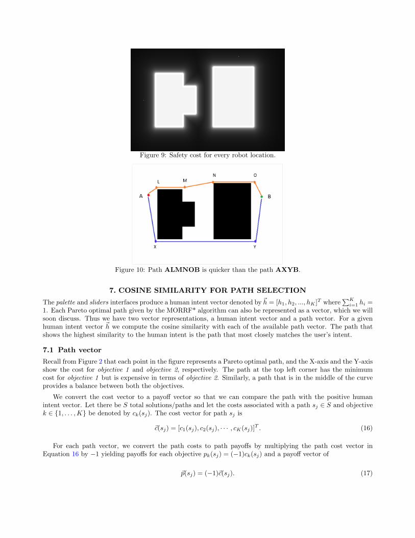
Figure 9: Safety cost for every robot location.
Figure 10: Path ALMNOB is quicker than the path AXYB.
7. COSINE SIMILARITY FOR PATH SELECTION
The palette and sliders interfaces produce a human intent vector denoted by ~h = [h1, h2, ..., hK ]T where∑K
i=1 hi =1. Each Pareto optimal path given by the MORRF* algorithm can also be represented as a vector, which we willsoon discuss. Thus we have two vector representations, a human intent vector and a path vector. For a givenhuman intent vector ~h we compute the cosine similarity with each of the available path vector. The path thatshows the highest similarity to the human intent is the path that most closely matches the user’s intent.
7.1 Path vector
Recall from Figure 2 that each point in the figure represents a Pareto optimal path, and the X-axis and the Y-axisshow the cost for objective 1 and objective 2, respectively. The path at the top left corner has the minimumcost for objective 1 but is expensive in terms of objective 2. Similarly, a path that is in the middle of the curveprovides a balance between both the objectives.
We convert the cost vector to a payoff vector so that we can compare the path with the positive humanintent vector. Let there be S total solutions/paths and let the costs associated with a path sj ∈ S and objectivek ∈ {1, . . . ,K} be denoted by ck(sj). The cost vector for path sj is
~c(sj) = [c1(sj), c2(sj), · · · , cK(sj)]T . (16)
For each path vector, we convert the path costs to path payoffs by multiplying the path cost vector inEquation 16 by −1 yielding payoffs for each objective pk(sj) = (−1)ck(sj) and a payoff vector of
~p(sj) = (−1)~c(sj). (17)
Next, from among all the solutions S, we determine the minimum and the maximum payoff values for eachof the objectives.
The payoff values in Equation 17 can be normalized to the bounds [0.0, 1.0] using the formula
pk(sj) =pk(sj)−mins`∈S{pk(s`)}
maxs`∈S{pk(s`)} −mins`∈S{pk(s`)}.
The corresponding normalized vector is given by
p(sj) = [p1(sj), p2(sj), · · · , pK(sj)]T . (18)
7.2 Cosine Similarity
The cosine similarity between a path vector, p(sj), and the human intent vector is h is:
CosineSimilarity(h,p(sj)) =h · p(sj)
‖h‖‖p(sj)‖=
∑Kk=1 hkpk(sj)√∑K
k=1 h2k
√∑Kk=1 p
2k(sj)
(19)
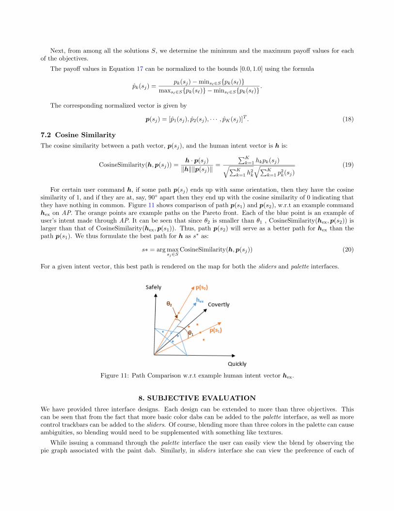
For certain user command h, if some path p(sj) ends up with same orientation, then they have the cosinesimilarity of 1, and if they are at, say, 90◦ apart then they end up with the cosine similarity of 0 indicating thatthey have nothing in common. Figure 11 shows comparison of path p(s1) and p(s2), w.r.t an example commandhex on AP. The orange points are example paths on the Pareto front. Each of the blue point is an example ofuser’s intent made through AP. It can be seen that since θ2 is smaller than θ1 , CosineSimilarity(hex,p(s2)) islarger than that of CosineSimilarity(hex,p(s1)). Thus, path p(s2) will serve as a better path for hex than thepath p(s1). We thus formulate the best path for h as s∗ as:
s∗ = arg maxsj∈S
CosineSimilarity(h,p(sj)) (20)
For a given intent vector, this best path is rendered on the map for both the sliders and palette interfaces.
Figure 11: Path Comparison w.r.t example human intent vector hex.
8. SUBJECTIVE EVALUATION
We have provided three interface designs. Each design can be extended to more than three objectives. Thiscan be seen that from the fact that more basic color dabs can be added to the palette interface, as well as morecontrol trackbars can be added to the sliders. Of course, blending more than three colors in the palette can causeambiguities, so blending would need to be supplemented with something like textures.
While issuing a command through the palette interface the user can easily view the blend by observing thepie graph associated with the paint dab. Similarly, in sliders interface she can view the preference of each of

the adverbs in the textboxes below the sliders. By mapping the intent vector to a path vector via the paletteor sliders interface, every user action updates the map immediately thereby giving the idea to the user of theimmediate consequences of her action/command.
Each interface has it benefits and limitations. On the palette it is possible to have multiple user created paintdabs, each representing a particular command. Such a history is not available with sliders, because the momentone of the sliders is moved, the map gets updated to show the recent path according to the current user’s action.On the other hand, while moving one of the adverb sliders it is possible to discover different paths associatedwith the different adverb values till certain adverb value is reached. The palette is devoid of this.
The user can also provide waypoints on the map to obtain a certain path. The resulting score for thiswaypoints path is calculated based on the cost of each path point given in subsections 4.3 and 5.1
9. SUMMARY AND FUTURE WORK
We have presented here three interfaces for exploring tradeoffs between robot paths with three objectives. Inthe future we plan to conduct a user study to measure which of the interfaces the user like, which is more easierto operate, and would capture time statistics with respect to each interface.
ACKNOWLEDGMENTS
This work is supported by the Army RCTA program. All results and conclusions are the responsibility of theauthors and do not necessarily reflect the opinions of the funding source.
REFERENCES
[1] LaValle, S. M., “Rapidly-exploring random trees a new tool for path planning,” (1998).
[2] Bruce, J. and Veloso, M., “Real-time randomized path planning for robot navigation,” in [Intelligent Robotsand Systems, 2002. IEEE/RSJ International Conference ], 3, 2383–2388, IEEE (2002).
[3] Bry, A. and Roy, N., “Rapidly-exploring random belief trees for motion planning under uncertainty,” in[Robotics and Automation (ICRA), 2011 IEEE International Conference ], 723–730, IEEE (2011).
[4] Yi, D., Goodrich, M. A., and Seppi, K. D., “MORRF*: Sampling-based multi-objective motion planning,” in[Proceedings of the 24th International Conference on Artificial Intelligence ], 1733–1739, AAAI Press (2015).
[5] Kavraki, L. E., Svestka, P., Latombe, J.-C., and Overmars, M. H., “Probabilistic roadmaps for path planningin high-dimensional configuration spaces,” Robotics and Automation, IEEE Transactions on 12(4), 566–580(1996).
[6] Ahmed, F. and Deb, K., “Multi-objective optimal path planning using elitist non-dominated sorting geneticalgorithms,” Soft Computing 17(7), 1283–1299 (2013).
[7] Wallenius, J. and Zionts, S., [Multiple criteria decision making: From early history to the 21st century ],World Scientific (2011).
[8] Hwang, C.-L. and Yoon, K., [Multiple attribute decision making: Methods and applications a state-of-the-artsurvey ], vol. 186, Springer Science & Business Media (2012).
[9] Gal, T., Stewart, T., and Hanne, T., [Multicriteria decision making: Advances in MCDM models, algorithms,theory, and applications ], vol. 21, Springer Science & Business Media (2013).
[10] Bennett, K. B. and Flach, J. M., [Display and interface design: Subtle science, exact art ], CRC Press (2011).
[11] Vicente, K. J. and Rasmussen, J., “Ecological interface design: Theoretical foundations,” Systems, Manand Cybernetics, IEEE Transactions on 22(4), 589–606 (1992).
[12] Bennett, K. B., Posey, S. M., and Shattuck, L. G., “Ecological interface design for military command andcontrol,” Journal of Cognitive Engineering and Decision Making 2(4), 349–385 (2008).
[13] Hall, D. S., Shattuck, L. G., and Bennett, K. B., “Evaluation of an ecological interface design for militarycommand and control,” Journal of Cognitive Engineering and Decision Making 6(2), 165–193 (2012).
[14] Kadous, M. W., Sheh, R. K.-M., and Sammut, C., “Effective user interface design for rescue robotics,” in[Proceedings of the 1st ACM SIGCHI/SIGART Conference on Human-robot interaction ], 250–257, ACM(2006).
[15] Chen, J. Y., Haas, E. C., and Barnes, M. J., “Human performance issues and user interface design forteleoperated robots,” Systems, Man, and Cybernetics, Part C: Applications and Reviews, IEEE Transactionson 37(6), 1231–1245 (2007).
[16] Baker, M., Casey, R., Keyes, B., and Yanco, H. A., “Improved interfaces for human-robot interaction inurban search and rescue.,” in [SMC (3) ], 2960–2965, Citeseer (2004).
[17] Adams, J. A., “Critical considerations for human-robot interface development,” in [Proceedings of 2002AAAI Fall Symposium ], 1–8 (2002).
[18] Rasmussen, J., “Skills, rules, and knowledge; Signals, signs, and symbols, and other distinctions in humanperformance models,” Systems, Man and Cybernetics, IEEE Transactions on (3), 257–266 (1983).
[19] Mahnke, F. H., [Color, environment, and human response: An interdisciplinary understanding of color andits use as a beneficial element in the design of the architectural environment ], John Wiley & Sons (1996).
[20] Sheridan, T. B., [Telerobotics, automation, and human supervisory control ], MIT press (1992).
[21] Lin, L. and Goodrich, M. A., “Sliding autonomy for UAV path-planning: Adding new dimensions to au-tonomy management,” in [Proceedings of the 2015 International Conference on Autonomous Agents andMultiagent Systems ], 1615–1624, International Foundation for Autonomous Agents and Multiagent Systems(2015).
[22] Goodrich, M. A. and Schultz, A. C., “Human-robot interaction: A survey,” Foundations and trends inhuman-computer interaction 1(3), 203–275 (2007).
[23] Fang, H., Ong, S., and Nee, A., “Novel AR-based interface for human-robot interaction and visualization,”Advances in Manufacturing 2(4), 275–288 (2014).
[24] Driewer, F., Sauer, M., and Schilling, K., “Discussion of challenges for user interfaces in human-robotteams.,” in [EMCR ], Citeseer (2007).
[25] Parasuraman, R., Sheridan, T. B., and Wickens, C. D., “A model for types and levels of human interac-tion with automation,” Systems, Man and Cybernetics, Part A: Systems and Humans, IEEE Transactionson 30(3), 286–297 (2000).
[26] Goodrich, M. A., McLain, T. W., Anderson, J. D., Sun, J., and Crandall, J. W., “Managing autonomyin robot teams: Observations from four experiments,” in [Proceedings of the ACM/IEEE InternationalConference on Human-robot interaction ], 25–32, ACM (2007).
[27] Johnson, M., Bradshaw, J. M., Feltovich, P. J., Jonker, C. M., van Riemsdijk, B., and Sierhuis, M., “Thefundamental principle of coactive design: Interdependence must shape autonomy,” in [Coordination, orga-nizations, institutions, and norms in agent systems VI ], 172–191, Springer (2011).
[28] Phillips, E., Ososky, S., Grove, J., and Jentsch, F., “From tools to teammates toward the development ofappropriate mental models for intelligent robots,” in [Proceedings of the Human Factors and ErgonomicsSociety Annual Meeting ], 55(1), 1491–1495, SAGE Publications (2011).
[29] Fong, T., Thorpe, C., and Baur, C., “Collaboration, dialogue, human-robot interaction,” in [Robotics Re-search ], 255–266, Springer (2003).
[30] Talone, A. B., Phillips, E., Ososky, S., and Jentsch, F., “An evaluation of human mental models of tacticalrobot movement,” in [Proceedings of the Human Factors and Ergonomics Society Annual Meeting ], 59(1),1558–1562, SAGE Publications (2015).
[31] Phillips, E., Ososky, S., and Jentsch, F., “An investigation of human decision-making in a human—robotteam task,” in [Proceedings of the Human Factors and Ergonomics Society Annual Meeting ], 58(1), 315–319,SAGE Publications (2014).
[32] Russell, S. and Norvig, P., [Artificial intelligence: A modern approach ] (1995).
[33] Kim, Y.-H., Rana, S., and Wise, S., “Exploring multiple viewshed analysis using terrain features andoptimisation techniques,” Computers & Geosciences 30(9), 1019–1032 (2004).
[34] STUCKY, J. L. D., “On applying viewshed analysis for determining least-cost paths on digital elevationmodels,” International Journal of Geographical Information Science 12(8), 891–905 (1998).
[35] Wang, J., Robinson, G. J., and White, K., “A fast solution to local viewshed computation using grid-baseddigital elevation models,” Photogrammetric Engineering and Remote Sensing 62(10), 1157–1164 (1996).