interaction of dual band helical and pifa handset … · of the helical antenna, in presence of...
TRANSCRIPT

Progress In Electromagnetics Research, PIER 77, 225–242, 2007
INTERACTION OF DUAL BAND HELICAL AND PIFAHANDSET ANTENNAS WITH HUMAN HEAD ANDHAND
M. A. Ebrahimi-Ganjeh
Communication and Computer Research CenterFerdowsi University of Mashad, Iran
A. R. Attari
Electrical Engineering DepartmentFerdowsi University of Mashad, Iran
Abstract—Helical antenna and planar inverted-F antenna (PIFA)are two commonly used handset antennas. This paper presents acomprehensive study on the performance of a dual band PIFA anda dual band helical antenna designed for operating in GSM900 andDCS1800 frequency bands. Radiation patterns and VSWR of theseantennas are computed in free space as well as in the presence ofhead and hand. The specific absorption rate (SAR) of the helicalantenna is calculated and compared with that of the PIFA handsetantenna. The peak average SAR in the head is compared with SARlimits in the safety standards and so the maximum radiation power ofeach antenna is determined. In addition, radiation efficiencies of thesehandset antennas are computed in the presence of head and hand. Allnumerical simulations are performed using the Ansoft HFSS software.Numerical simulations results are in good agreement with publishedmeasurement results.
1. INTRODUCTION
Interaction of handset antennas with human body is a greatconsideration in cellular communications. The user’s body, especiallyhead and hand, influence on the antenna voltage standing wave ratio(VSWR), gain and radiation patterns. Furthermore, thermal effect,when tissues exposed to unlimited electromagnetic energy, can be a

226 Ebrahimi-Ganjeh and Attari
serious health hazard. So standard organizations have set exposurelimits in terms of the specific absorption rate (SAR) [1, 2].
Simplified phone antennas such as half-wavelength dipoles in freespace or quarter-wavelength monopoles mounted on a metallic boxhave been frequently investigated in the literature. These antennas areno longer in widespread use for cellular phones and therefore it is notsuitable to use them for studying the interaction of handset antennasand nearby tissues. However, when it is desired to focus on the humanbody modeling it is reasonable to use a simple monopole or dipoleantenna [3, 4]. At the present time PIFA and helical antennas are twocommonly used handset antennas. Today, the handset antennas aredesigned to be able to support two or more frequency bands of variouscellular networks. It is required to perform a comprehensive studyto determine which handset antenna has better performance and lesshealth hazard. Also it is needed to determine which frequency band isbetter for operation.
In one of the first investigations in this area [5], a comparativestudy has been performed among a monopole antenna and somedifferent types of single band PIFA antennas. Size of the investigatedantennas and length of handset boxes used in [5] are considerablygreater than those used today. SAR and temperature rise in ahuman head have been calculated for electromagnetic radiation froma monopole, single band helix, single band patch and side mountedsingle band PIFA antenna at 900 MHz and 1800 MHz [6]. Effect ofthe separation distance between the antenna and user head has beenstudied for a dual band PIFA handset antenna [7]. This study hasshown that there is a proportional relation between SAR and antennaefficiency. In [8], SAR induced in a cubic head model by two singleband helical antenna, one radiates at 900 MHz and the other radiatesat 1800 MHz, has been calculated and the effect of mobile shell materialhas been studied. SAR and radiation efficiency has been measured forfour types of PIFA designed for the PCS frequency band (1850 MHz–1990 MHz) and it has been shown that handsets with higher-efficiencyantennas might not necessarily have higher total radiated power dueto the SAR limit [9]. The head loss for twenty different mobile phones,with external and built-in antennas, has been measured [10]. Themeasured results have been compared, it has been shown that thehandsets with built-in antennas are much less sensitive to how thephone is held than the handsets with external antennas. In [11],interaction of a single band helical antenna, mounted on a metallicbox, with a human spherical head model has been investigated andreported. SAR level in head from a monopole, a helix and a patchantenna at 1.8 GHz has been computed and it has been shown that the
Progress In Electromagnetics Research, PIER 77, 2007 227
patch antenna produces the lowest SAR in the head tissues [12]. Fora helical antenna operating at 900 MHz, the SAR quantity, radiationpatterns and radiation efficiency in the presence of human head andhand has been computed [13]. In another investigation, interaction ofa dual band gap loop antenna with human head and hand has beeninvestigated [14].
In this paper, performance of a dual band helix (as an externalantenna) and a dual band PIFA (as a built-in antenna) is evaluatedin the presence of head and hand model. In this study, all radiationcharacteristics including radiation patterns, radiation efficiency andVSWR are examined. In addition, the SAR quantity is computed forboth the helical and PIFA antennas. Both of the investigated antennasare designed so that they cover the frequency bands of GSM900(890 MHz–960 MHz) and DCS1800 (1710 MHz–1880MHz). As pointedout before, all numerical simulations are performed using the AnsoftHFSS software.
2. POWER ABSORPTION AND SAR
Energy absorption in biological tissues is characterized by SpecificAbsorption Rate (SAR). SAR is defined as the time derivative ofthe incremental energy (dW ) dissipated in an incremental mass (dm)contained in a volume element (dV ) of a given density (ρ) [15, 16]:
SAR =d
dt
(dW
dm
)=
d
dt
(dW
ρdV
)(W/kg) (1)
The SAR quantity is related to the internal E-field by:
SAR =σE2
ρ(W/kg) (2)
where, ρ is the mass density in kg/m3 and E is the root mean square(rms) of electric field strength in volts per meter. The concept ofSAR is meaningful only in the frequency range between approximately100 kHz and 6 GHz–10 GHz, i.e., where the penetration depth of theelectromagnetic energy in the tissue is of the order of 1 cm or more[16].
The local SAR averaged over a specified 1 gram or 10 gram mass,is called 1-g or 10-g spatial average SAR. Comparison of averagingprocedures for SAR distributions has been presented in [17].
If the metabolic heating rate, blood flowing cooling rate and theheat losses rate for a tissue have been neglected, the relation between

228 Ebrahimi-Ganjeh and Attari
SAR, duration of exposure (dt) and change in temperature (dT ) is [18]:
dT
dt=
SAR
c(C/s) (3)
where, c is specific heat capacity (J/kg C). Thus, a SAR of 1 W/kgis associated with a heating rate less than 0.0003C/s in muscle tissue(c = 3.5 kJ/kg C), a very small heating rate since it would take morethan 1 hour to increase the temperature 1 degree Celsius.
If we consider the effect of blood flow and metabolic heating rate,the temperature change due to the induced SAR can be obtained bysolving the bio-heat equation [19].
3. HEAD AND HAND MODEL
Biological tissues are modeled by their permittivity and conductivity.The complex permittivity (ε) of a biological tissue is given by:
ε = εrε0 + jσ
ω(4)
where, σ (S/m) is the conductivity of tissue in siemens per meter andε0 = 8.854 × 10⁻¹² F/m. The relative dielectric constant (εr) andconductivity of various tissues over the frequency range of 10 kHz–10 GHz are available at [20, 21].
High-resolution models of the human head derived from magneticresonance imaging (MRI) scans [22] can provide accurate results,however such a detailed model requires a lot of computational timein the numerical methods [23]. Compared with a real head, flat andcubic model of head may cause considerable changes in antenna loading[15]. Spherical models of appropriate diameter provide a reasonableaccuracy for power absorption characterization. It should be notedthat when a spherical structure is used for modeling the head, the tiltangle of the nearby handset can be neglected.
In this paper a simplified homogeneous spherical head model willbe used. Diameter of this spherical model is 213 mm and propertiesof the head tissue-equivalent dielectric for both the GSM and DCSfrequency bands are shown in Table 1. For computation of SAR thehead tissue density is assumed to be 1000 kg/m3 [15].
In the majority of studies, SAR induced by a handset is computedwithout a hand. Neglecting the effect of hand usually results in anoverestimation of the SAR in the head [15]. This overestimation leadsto have more safety factor when the head SAR computations comparedwith the standards. Moreover numerical and experimental studieshave shown that SAR in the hand is low compared with the SAR

Progress In Electromagnetics Research, PIER 77, 2007 229
Table 1. Properties of the tissue-equivalent dielectric used for thespherical head model [15].
Frequency Relative permittivity, rε Conductivity, σ (S/m)
900MHz .5 0.97
1800MHz 1.4
41
40
in the head [15]. However, the effect of hand on the antenna radiationcharacteristics is significant and can not be neglected [5, 24].
Figure 1. Simplified model of the human hand. (a) Cross section ofthe hand model [5]. (b) Position of a handset placed in a hand.
As illustrated in Fig. 1, in this paper we use a simplified model ofhand [5] in which a layer of bone is surrounded by a layer of muscle.This model covers three sides of the handset. Dielectric properties oftissues used in hand model are shown in Table 2 [21].
In all numerical simulations, it is assumed that dielectricproperties of tissues are constant over the entire GSM or DCSbandwidth.
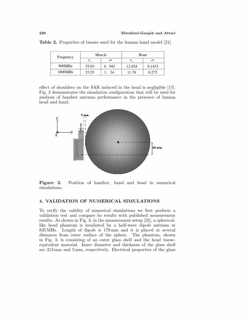
The relative distance between the head and handset has a stronginfluence on SAR. Under normal use conditions of a handset, it touchesthe ear. To take into account the effect of ear thickness, we assumethat the handset is held at a distance of 5 mm from the head. It shouldbe noted that when the handset is held at 5 mm from the head, the
230 Ebrahimi-Ganjeh and Attari
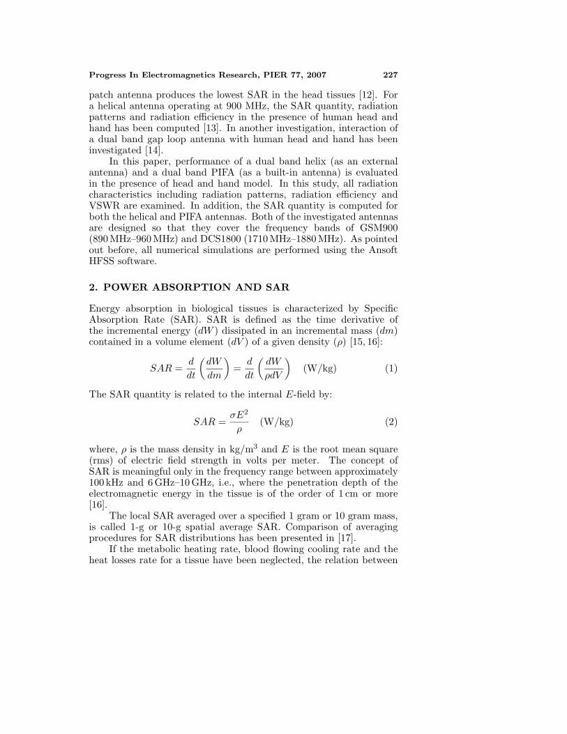
Table 2. Properties of tissues used for the human hand model [21].
Muscle Bone Frequency rε σ rε σ
900MHz 55.03 0. 943 12.454 0.1433
1800MHz 53.55 1. 34 11.78 0.275
effect of shoulders on the SAR induced in the head is negligible [15].Fig. 2 demonstrates the simulation configuration that will be used foranalysis of handset antenna performance in the presence of humanhead and hand.
Figure 2. Position of handset, hand and head in numericalsimulations.
4. VALIDATION OF NUMERICAL SIMULATIONS
To verify the validity of numerical simulations we first perform avalidation test and compare its results with published measurementresults. As shown in Fig. 3, in the measurement setup [25], a spherical-like head phantom is irradiated by a half-wave dipole antenna at835 MHz. Length of dipole is 178 mm and it is placed at severaldistances from outer surface of the sphere. The phantom, shownin Fig. 3, is consisting of an outer glass shell and the head tissue-equivalent material. Inner diameter and thickness of the glass shellare 213 mm and 5 mm, respectively. Electrical properties of the glass
Progress In Electromagnetics Research, PIER 77, 2007 231
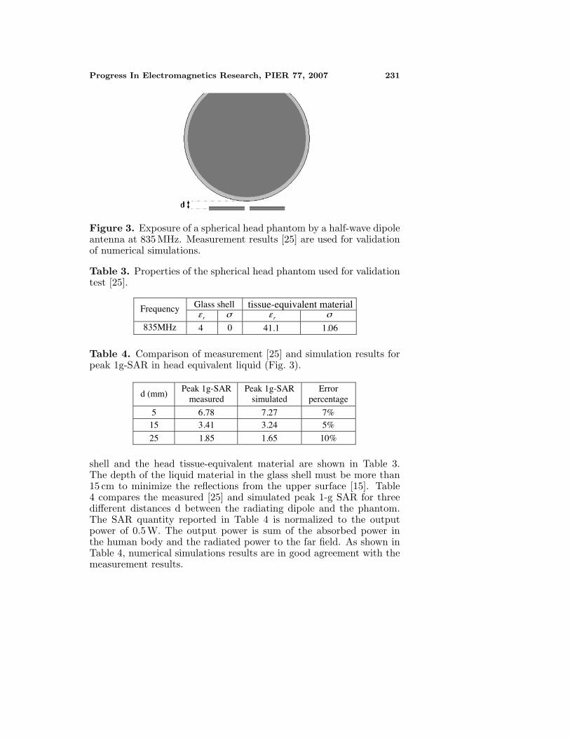
Figure 3. Exposure of a spherical head phantom by a half-wave dipoleantenna at 835 MHz. Measurement results [25] are used for validationof numerical simulations.
Table 3. Properties of the spherical head phantom used for validationtest [25].
Glass shell tissue-equivalent material Frequency rε σ rε σ
835MHz 4 41.1 1.060
Table 4. Comparison of measurement [25] and simulation results forpeak 1g-SAR in head equivalent liquid (Fig. 3).
d (mm) Peak 1g-SAR
measured Peak 1g-SAR
simulated Error
percentage
5 78 7.27 7%15 41 3.24 5%
25 85 1.65 10%
6.3.
1.
shell and the head tissue-equivalent material are shown in Table 3.The depth of the liquid material in the glass shell must be more than15 cm to minimize the reflections from the upper surface [15]. Table4 compares the measured [25] and simulated peak 1-g SAR for threedifferent distances d between the radiating dipole and the phantom.The SAR quantity reported in Table 4 is normalized to the outputpower of 0.5 W. The output power is sum of the absorbed power inthe human body and the radiated power to the far field. As shown inTable 4, numerical simulations results are in good agreement with themeasurement results.
232 Ebrahimi-Ganjeh and Attari
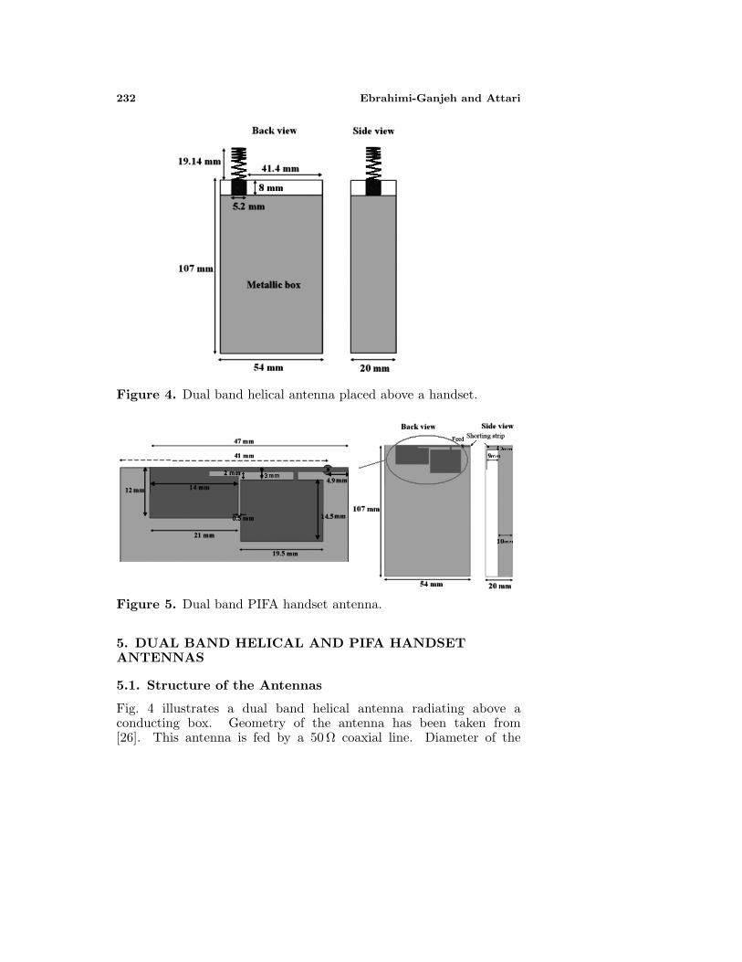
Figure 4. Dual band helical antenna placed above a handset.
Figure 5. Dual band PIFA handset antenna.
5. DUAL BAND HELICAL AND PIFA HANDSETANTENNAS
5.1. Structure of the Antennas
Fig. 4 illustrates a dual band helical antenna radiating above aconducting box. Geometry of the antenna has been taken from[26]. This antenna is fed by a 50 Ω coaxial line. Diameter of the
Progress In Electromagnetics Research, PIER 77, 2007 233
outer conductor and length of the coaxial line are 5.2 mm and 8 mm,respectively. Dimensions of the helix are optimized to obtain theminimum VSWR over the GSM and DCS frequency bands. Theoptimized helix is 19.14 mm long and has a diameter of 6.6 mm. Thefirst 3.25 turns have a pitch of 4 mm, followed by 4.7 turns with a pitchof 1.2 mm.
Fig. 5 demonstrates detailed model of a dual band PIFA antennaplaced in the back of a handset. To achieve the necessary bandwidth,the radiating part of PIFA is placed at a distance of 9 mm from theground plane. General structure of the antenna shown in Fig. 5 is takenfrom [27], however size of the ground plane and antenna dimensionsshown in this figure are different from those given in [27]. Dimensionsshown in Fig. 5 provide low VSWR at 900 MHz and 1800 MHz.
5.2. VSWR
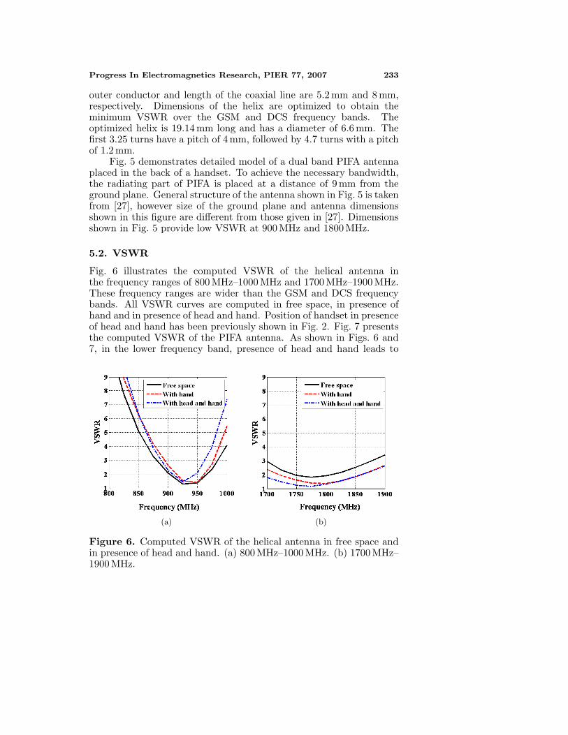
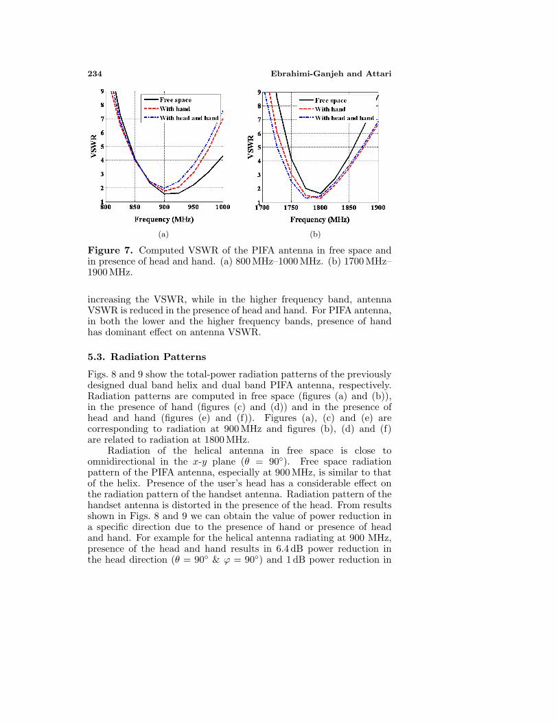
Fig. 6 illustrates the computed VSWR of the helical antenna inthe frequency ranges of 800 MHz–1000 MHz and 1700 MHz–1900MHz.These frequency ranges are wider than the GSM and DCS frequencybands. All VSWR curves are computed in free space, in presence ofhand and in presence of head and hand. Position of handset in presenceof head and hand has been previously shown in Fig. 2. Fig. 7 presentsthe computed VSWR of the PIFA antenna. As shown in Figs. 6 and7, in the lower frequency band, presence of head and hand leads to
(a) (b)
Figure 6. Computed VSWR of the helical antenna in free space andin presence of head and hand. (a) 800 MHz–1000 MHz. (b) 1700 MHz–1900 MHz.
234 Ebrahimi-Ganjeh and Attari
(a) (b)
Figure 7. Computed VSWR of the PIFA antenna in free space andin presence of head and hand. (a) 800 MHz–1000 MHz. (b) 1700 MHz–1900 MHz.
increasing the VSWR, while in the higher frequency band, antennaVSWR is reduced in the presence of head and hand. For PIFA antenna,in both the lower and the higher frequency bands, presence of handhas dominant effect on antenna VSWR.
5.3. Radiation Patterns
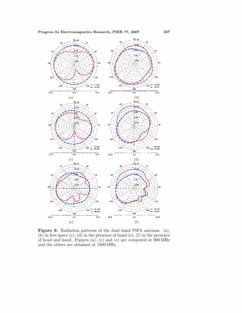
Figs. 8 and 9 show the total-power radiation patterns of the previouslydesigned dual band helix and dual band PIFA antenna, respectively.Radiation patterns are computed in free space (figures (a) and (b)),in the presence of hand (figures (c) and (d)) and in the presence ofhead and hand (figures (e) and (f)). Figures (a), (c) and (e) arecorresponding to radiation at 900 MHz and figures (b), (d) and (f)are related to radiation at 1800 MHz.
Radiation of the helical antenna in free space is close toomnidirectional in the x-y plane (θ = 90). Free space radiationpattern of the PIFA antenna, especially at 900 MHz, is similar to thatof the helix. Presence of the user’s head has a considerable effect onthe radiation pattern of the handset antenna. Radiation pattern of thehandset antenna is distorted in the presence of the head. From resultsshown in Figs. 8 and 9 we can obtain the value of power reduction ina specific direction due to the presence of hand or presence of headand hand. For example for the helical antenna radiating at 900 MHz,presence of the head and hand results in 6.4 dB power reduction inthe head direction (θ = 90 & ϕ = 90) and 1 dB power reduction in

Progress In Electromagnetics Research, PIER 77, 2007 235
Table 5. Variations in the radiated power of the helix and PIFAantenna in the azimuth plane (θ = 90) due to the presence of headand hand.
At 900 MHz At 1800 MHz Antenna
o90ϕ o90ϕ o90ϕ o90ϕ
Helix -1.0 dB -6.4 dB +1.1dB -18.0 dB
PIFA -2.8 dB -5.1 dB -0.8 dB -7.8 dB
= − = −= =
the hand direction (θ = 90 & ϕ = −90). Variations in the radiatedpower in the above two directions are presented in Table 5 for boththe helix and PIFA antenna. For all cases shown in Table 5, especiallyfor the helical antenna, reduction of the radiated power in the headdirection is greater than that in the hand direction.
5.4. SAR and Radiation Efficiency
Due to energy absorption in human body, radiated power of ahandset antenna is decreased. This decrement of radiated power ischaracterized by radiation efficiency (η). Antenna radiation efficiencyis defined as [5]:
η =Prad
Prad + Pabs=
Prad
Pdel(5)
where, Pabs is the power absorbed within lossy tissues, Prad is thepower radiated to the far field and Pdel is the power delivered tothe antenna. For a handset system increasing the radiation efficiencyresults in improvement of battery life. Table 6 presents the radiationefficiency of the helix and PIFA antenna in the presence of hand andin the presence of head and hand. As shown in this table, the headand hand absorb about 50% of the power delivered to the handsetantenna. Table 6 indicates that in the presence of only hand, radiationefficiency of the helix is greater than that of the PIFA antenna, whilein the presence of head and hand, radiation efficiency of the PIFAantenna is greater than that of the helix.
Power absorption in the head is characterized by the SARquantity. For both the helical and PIFA antennas radiating in thepresence of head and hand, the peak spatial average SAR values areshown in Table 7. This table indicates that the SAR in the headinduced by a PIFA antenna is about half of that induced by a helicalantenna. As pointed out before, standard organizations have setexposure limits in terms of the SAR. According to the US standards, forRF exposure in uncontrolled environments (public exposure) the SAR

236 Ebrahimi-Ganjeh and Attari
(a) (b)
(c) (d)
(e) (f)
Figure 8. Radiation patterns of the dual band helical antenna. (a),(b) in free space (c), (d) in the presence of hand (e), (f) in the presenceof head and hand. Figures (a), (c) and (e) are computed at 900 MHzand the others are obtained at 1800 MHz.
Progress In Electromagnetics Research, PIER 77, 2007 237
(a) (b)
(c) (d)
(e) (f)
Figure 9. Radiation patterns of the dual band PIFA antenna. (a),(b) in free space (c), (d) in the presence of hand (e), (f) in the presenceof head and hand. Figures (a), (c) and (e) are computed at 900 MHzand the others are obtained at 1800 MHz.

238 Ebrahimi-Ganjeh and Attari
Table 6. Radiation efficiency (η) in the presence of hand or in thepresence of head and hand.
At 900MHz At 1800MHzAntenna
Hand Head and hand Hand Head and hand
Helix 82.3% 43.5% 83.4% 53.5%
PIFA 63.9% 43.8% 78.5% 60%
limit is 1.6 W/kg averaged over 1 g of tissue. In Europe, AustraliaJapan and some other countries, the spatial average SAR limit forpublic exposure is 2 W/kg averaged over 10 g of tissue [28].
An important characteristic of a handset antenna is its TotalRadiated Power (TRP). TRP is defined as the maximum radiatedpower of the handset antenna to the far field which is limited by theSAR requirement [9]. For example for the PIFA antenna radiatingat 900 MHz, when the power delivered to the antenna is 0.25 W, thepeak 1-g SAR is 0.714 W/kg (see Table 7); hence the maximum powerdelivered to the antenna corresponding to 1-g SAR of 1.6 W/kg is0.56 W. Radiation efficiency of the PIFA antenna at 900 MHz is 43.8%and so the maximum power that this antenna can radiate to the farfield, which is defined as the TRP, is 0.245 W.
Table 7. Peak SAR (W/kg) in the head when the handset antenna isradiating in the presence of head and hand (Pdel = 0.25 W).
At 900MHz At 1800MHz Antenna
1-g SAR 10-g SAR 1-g SAR 10-g SAR
Helix 0.965 1.81 1.15PIFA 4 0.51 0.772 0.524
1.31 0.71
TRP provides a good evaluation of the antenna performance fromthe system point of view [9]. Increasing the TRP of a handset antennacan significantly improve the call performance in a weak signal area.Table 8 presents the TRP of the helix and PIFA antenna in the presenceof head and hand at 900 and 1800 MHz. As shown in this table, inboth the lower and higher frequency bands, TRP of the PIFA antennais greater than that of the helix.
Progress In Electromagnetics Research, PIER 77, 2007 239
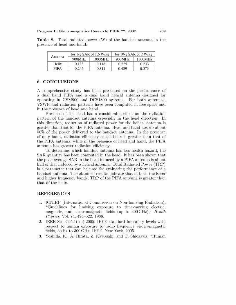
Table 8. Total radiated power (W) of the handset antenna in thepresence of head and hand.
for 1-g SAR of 1.6 W/kg for 10-g SAR of 2 W/kg Antenna
900MHz 1800MHz 900MHz 1800MHzHelix 0.133 8 5 3PIFA 0.245 1 9 3
0.110.31
0.220.42
0.230.57
6. CONCLUSIONS
A comprehensive study has been presented on the performance ofa dual band PIFA and a dual band helical antenna designed foroperating in GSM900 and DCS1800 systems. For both antennas,VSWR and radiation patterns have been computed in free space andin the presence of head and hand.
Presence of the head has a considerable effect on the radiationpattern of the handset antenna especially in the head direction. Inthis direction, reduction of radiated power for the helical antenna isgreater than that for the PIFA antenna. Head and hand absorb about50% of the power delivered to the handset antenna. In the presenceof only hand, radiation efficiency of the helix is greater than that ofthe PIFA antenna, while in the presence of head and hand, the PIFAantenna has greater radiation efficiency.
To determine which handset antenna has less health hazard, theSAR quantity has been computed in the head. It has been shown thatthe peak average SAR in the head induced by a PIFA antenna is abouthalf of that induced by a helical antenna. Total Radiated Power (TRP)is a parameter that can be used for evaluating the performance of ahandset antenna. The obtained results indicate that in both the lowerand higher frequency bands, TRP of the PIFA antenna is greater thanthat of the helix.
REFERENCES
1. ICNIRP (International Commission on Non-Ionizing Radiation),“Guidelines for limiting exposure to time-varying electric,magnetic, and electromagnetic fields (up to 300 GHz),” HealthPhysics, Vol. 74, 494–522, 1988.
2. IEEE Std C95.1(tm)-2005, IEEE standard for safety levels withrespect to human exposure to radio frequency electromagneticfields, 3 kHz to 300 GHz, IEEE, New York, 2005.
3. Yoshida, K., A. Hirata, Z. Kawasaki, and T. Shiozawa, “Human
240 Ebrahimi-Ganjeh and Attari
head modeling for handset antenna design at 5 GHz band,”Journal of Electromagnetic Waves and Application, Vol. 19, No. 3,401–411, 2005.
4. Kiminami, K., A. Hirata, Y. Horii, and T. Shiozawa, “AStudy on human body modeling for the mobile terminal antennadesign at 400 MHz band,” Journal of Electromagnetic Waves andApplication, Vol. 19, No. 5, 671–687, 2005.
5. Jensen, M. A. and Y. Rahamat-Samii, “EM interaction of handsetantennas and a human in personal communication,” Proceeding ofthe IEEE, Vol. 83, No. 1, 7–17, January 1995.
6. Yioultsis, T. V., T. I. Kosmanis, E. P. Kosmidou, T. T. Zygiridis,N. V. Kantartzis, T. D. Xenos, and T. D. Tsiboukis, “Acomparative study of the biological effects of various mobile phoneand wireless LAN antennas,” IEEE Trans. Magnetics, Vol. 38,No. 3, 777–780, 2002.
7. Saraereh, O. A., M. Jayawadene, P. McEvoy, and J. C. Vardax-oglou, “Simulation and experimental SAR and efficiency studyfor a dual-band PIFA handset antenna (GSM 900/DCS 1800) atvaried distances from a phantom head,” Technical Seminar onAntenna Measurements and SAR (AMS), 5–8, 2004.
8. Jin, M., Z. Ying, and S. He, “The impact of mobile shell materialson SAR,” Asia-Pacific Microwave Conference Proceedings, Vol. 5,2005.
9. Li, Z. and Y. Rahmat-Samii, “SAR in PIFA handset antennadesigns: an overall system perspective,” IEEE Antennas andPropagation Society International Symposium, Vol. 2B, 784–787,2005.
10. Kildal, P. S. and C. Carlson, “Comparison between head lossesof 20 phones with external and built-in antennas measured inreverberation chamber,” IEEE Antennas and Propagation SocietyInternational Symposium, Vol. 1, 436–439, 2002.
11. Kouveliotis, N. K., S. C. Panagiotou, P. K. Varlamos, andC. N. Capsalis, “Theoritical approach of the interaction betweena human head model and a mobile handset helical antennausing numerical methods,” Progress In Electromagnetics Research,PIER 65, 309–327, 2006.
12. Popovic, M., Q. Han, and H. Kanj, “A parallel study of SARlevels in head tissues for three antennas used in cellular telephones:monopole, helix and patch,” Springer Earth and EnvironmentalScience, Vol. 25, No. 2–4, 215–221, December 2005.
13. Ebrahimi-Ganjeh, M. A. and A. R. Attari, “Calculation of SpecificAbsorption Rate (SAR) and studying the radiation performance
Progress In Electromagnetics Research, PIER 77, 2007 241
of the helical antenna, in presence of head and hand model for900 MHz,” presented in 15th Iranian Conference on ElectricalEngineering (ICEE2007), Tehran, Iran, May 15–17, 2007.
14. Kuo, L.-C., Y.-C. Kan, and H.-R. Chuang, “Analysis of a900/1800-MHz dual-band gap loop antenna on a handset withproximate head and hand model,” Journal of ElectromagneticWaves and Application, Vol. 21, No. 1, 107–122, 2007.
15. IEEE Std 1528TM-2003, IEEE recommended practice fordetermining the peak spatial-average Specific Absorption Rate(SAR) in the human head from wireless communications devices:measurement techniques, IEEE, New York, 2003.
16. Adair, E. R. and R. C. Peterson, “Biological effects of radio-frequency/microwave radiation,” IEEE Trans. MTT, Vol. 50,No. 3, 953–961, 2002.
17. Stevens, N. and L. Martens, “Comparison of averaging proceduresfor SAR distributions at 900 and 1800 MHz,” IEEE, Trans. MTT,Vol. 48, No. 11, 2180–2184, 2000.
18. Vorst, A. V., A. Rosen, and Y. Kotsuka, RF/MicrowaveInteraction with Biological Tissues, John Wiley, 2006.
19. Ibrahiem, A. and C. Dale, “Analysis of the temperature increaselinked to the power induced by RF source,” Progress InElectromagnetics Research, PIER 52, 23–46, 2005.
20. Gabriel, C., S. Gabriely, and E. Corthout, “The dielectricproperties of biological tissues: I. Literature survey,” Phys. Med.Biol., Vol. 41, 2231–2249, 1996.
21. Gabriel, C., “Compilation of the dielectric properties of bodytissues at RF and microwave frequencies,” Armstrong Lab.,Brooks Air Force Base, TX, Brooks Air Force Base Tech. Rep.AL/OE-TR-1996-0037, June 1996.
22. Gandhi, O. P., G. Lazzi, and C. M. Furse, “Electromagneticabsorption in the human head and neck for mobile telephonesat 835 MHz and 1900 MHz,” IEEE Trans. MTT, Vol. 44, No. 10,1884–1897, 1996.
23. Kang, X. K., L. W. Li, M. S. Leong, and P. S. Kooi, “A spheroidalvector wave function analysis of field and SAR distributions ina dielectric prolate spheroidal human head model,” Progress InElectromagnetics Research, PIER 22, 149–179, 1999.
24. Francavilla, M., A. Schiavoni, P. bertotto, and G. Richiardi,“Effect of hand on cellular phone radiation,” IEE Proc. Microw.Antennas Propag., Vol. 148, No. 4, 2001.

242 Ebrahimi-Ganjeh and Attari
25. Yu, Q. and O. P. Gandhi, “An automated SAR measurementsystem for compliance testing of personal wireless devices,” IEEETrans. EMC, Vol. 41, No. 3, 234–244, 1999.
26. Pisa, S., M. Cavagnaro, V. Lopresto, E. Piuzzi, G. A. Lovisolo,and P. Bernardi, “A procedure to develop realistic numericalmodels of cellular phones for an accurate evaluation of SARdistribution in the human head,” IEEE Trans. MTT, Vol. 53,No. 4, 1256–1265, 2005.
27. Abedin, M. F. and M. Ali, “Modifying the ground plane andits effect on planar inverted-F antennas (PIFA) for mobile phonehandsets,” IEEE Antennas and Wireless Propag. Letters, Vol. 2,226–229, 2003.
28. Chen, Z. N., Antennas for Portable Devices, Wiley, 2007.