intelidrive id mobile - dornamehr.com r3 referenc… · id-mobile,sw version 1.7, ©comap – march...
TRANSCRIPT
ComAp a.s. Kundratka 2359/17, 180 00 Praha 8, Czech Republic Tel: +420 246 012 111, Fax: +420 266 316 647 E-mail: [email protected], www.comap.cz Support: [email protected] Copyright © 2008-2013 ComAp a.s. Written by: KKMN, RJZD
Reference Guide
InteliDrive
ID–Mobile
Expandable automotive engine controller
with electronic engines support
Single speed applications SS All speed applications AS
SW version 1.7, March 2013

ID-Mobile,SW version 1.7, ©ComAp – March 2013 - 2 -
Table of Contents
Table of Contents .......................................................................................................................................... - 2 - Document information .................................................................................................................................... - 4 -
Clarification of notation .............................................................................................................................. - 4 - Conformity declaration .............................................................................................................................. - 4 -
Related........................................................................................................................................................... - 5 - Software .................................................................................................................................................... - 5 - PC Tools .................................................................................................................................................... - 5 - Documentation .......................................................................................................................................... - 5 -
General guidelines ......................................................................................................................................... - 6 - What is ID-Mobile? .................................................................................................................................... - 6 - Features .................................................................................................................................................... - 6 -
Hardware ....................................................................................................................................................... - 7 - LED indication ........................................................................................................................................... - 7 - Dimensions and assembly ........................................................................................................................ - 8 - Harnesses ................................................................................................................................................. - 8 - ID-Mobile Service Module ....................................................................................................................... - 10 - Terminals ................................................................................................................................................. - 11 - Physical input/output structure ................................................................................................................ - 12 - Jumpers – hardware configuration .......................................................................................................... - 17 - Plug in modules ....................................................................................................................................... - 24 - External displays ..................................................................................................................................... - 25 - Communication lines ............................................................................................................................... - 27 -
Modules ....................................................................................................................................................... - 29 - ID-Mobile Master - Slave concept ........................................................................................................... - 29 -
Binary Inputs ................................................................................................................................................ - 30 - Binary outputs .............................................................................................................................................. - 35 -
Source: Log Bout ..................................................................................................................................... - 35 - Source – Prg.states ................................................................................................................................ - 40 -
Logical Analog Inputs list ............................................................................................................................. - 43 - Analog inputs configuration example ...................................................................................................... - 44 -
Analog Values (logical outputs) ................................................................................................................... - 45 - Basic Values ............................................................................................................................................ - 45 - Engine Values ......................................................................................................................................... - 46 - Analog outputs availability ....................................................................................................................... - 47 - Analog CU ............................................................................................................................................... - 47 - Binary CU ................................................................................................................................................ - 48 - Log Bout .................................................................................................................................................. - 48 - Info ........................................................................................................................................................... - 48 - Statistics .................................................................................................................................................. - 50 - Position .................................................................................................................................................... - 50 -
Setpoints ...................................................................................................................................................... - 51 - Password ................................................................................................................................................. - 51 - Basic Settings .......................................................................................................................................... - 52 - Comms Settings ...................................................................................................................................... - 54 - Engine Params ........................................................................................................................................ - 55 - Engine Protect ......................................................................................................................................... - 59 - Analog Inputs .......................................................................................................................................... - 62 - Act. Calls/SMS ........................................................................................................................................ - 62 - Date and time .......................................................................................................................................... - 64 - Position .................................................................................................................................................... - 65 - Display ..................................................................................................................................................... - 65 - PWM Settings .......................................................................................................................................... - 65 - Protections............................................................................................................................................... - 66 - PLC .......................................................................................................................................................... - 66 -
Event log ...................................................................................................................................................... - 67 - Functions ..................................................................................................................................................... - 70 -

ID-Mobile,SW version 1.7, ©ComAp – March 2013 - 3 -
Default archives ....................................................................................................................................... - 70 - Operational modes .................................................................................................................................. - 70 - Protections............................................................................................................................................... - 70 - Engine start ............................................................................................................................................. - 71 - PWM and Dither ...................................................................................................................................... - 71 -
PLC - programmable functions .................................................................................................................... - 74 - PLC functions description ........................................................................................................................ - 77 -
Controller configuration and monitoring ....................................................................................................... - 88 - Direct connection to the PC ..................................................................................................................... - 88 - DriveConfig .............................................................................................................................................. - 88 - Configuration steps ................................................................................................................................. - 89 - DriveMonitor ............................................................................................................................................ - 89 - Password protection ................................................................................................................................ - 90 - Modbus protocol ...................................................................................................................................... - 90 - AirGate and WebSupervisor support ..................................................................................................... - 91 -
Booting procedure ....................................................................................................................................... - 94 - Technical data ............................................................................................................................................. - 98 -
Power Supply .......................................................................................................................................... - 98 - Operating conditions ............................................................................................................................... - 98 - Dimensions .............................................................................................................................................. - 98 - Binary inputs ............................................................................................................................................ - 98 - Binary outputs ......................................................................................................................................... - 98 - Analog inputs ........................................................................................................................................... - 99 - Analog outputs ........................................................................................................................................ - 99 - Speed pick-up input ................................................................................................................................. - 99 - Impulse input ........................................................................................................................................... - 99 - D+ funcion ............................................................................................................................................. - 100 - CAN bus interface ................................................................................................................................. - 100 - RS 485 ................................................................................................................................................... - 100 - ID-Mobile GPRS .................................................................................................................................... - 101 - ID-Mobile GSM ...................................................................................................................................... - 101 - ID-Mobile GPS ...................................................................................................................................... - 101 -

ID-Mobile,SW version 1.7, ©ComAp – March 2013 - 4 -
Document information
ID-MOBILE – REFERENCE GUIDE WRITTEN BY: KKMN, RJZD ©2013 COMAP LTD. KUNDRATKA 17, PRAHA 8, CZECH REPUBLIC PHONE: +420246012111, FAX: +420266316647 WEB: HTTP://WWW.COMAP.CZ, E-MAIL: [email protected]; [email protected] DOCUMENT HISTORY
REVISION NUMBER RELATED SW. VERSION DATE
ID-Mobile 1.7 1.7 5.2.2013
ID-Mobile 1.7 r1 1.7 (minor formal changes) 26.3.2013
ID-Mobile 1.7 r2 1.7 (minor formal changes) 11.12.2013
ID-Mobile 1.7 r3 1.7 (fix jumpers setting) 6.3.2014
Clarification of notation
NOTE: This type of paragraph calls readers attention to a notice or related theme. CAUTION! This type of paragraph highlights a procedure, adjustment etc., which can cause a damage or un-proper function of the equipment if not performed correctly and may not be clear at first sight. WARNING! This type of paragraph indicates things, procedures, adjustments etc. which need high level of attention, otherwise can cause personal injury or death.
Conformity declaration
Following described machine complies with the appropriate basic safety and health requirement of the EC Low Voltage Directive No: 73/23 / EEC and EC Electromagnetic Compatibility Directive 89/336 / EEC based on its design and type, as brought into circulation by us.
NOTE: ComAp believes that all information provided herein is correct and reliable and reserves the right to update at any time. ComAp does not assume any responsibility for its use unless otherwise expressly undertaken.

ID-Mobile,SW version 1.7, ©ComAp – March 2013 - 5 -
Related
CAUTION! Below mentioned versions are valid with the issuing of this document. For available updates follow ComAp web pages.
Software
RELATED SW. VERSION DATE
ID-Mobile-1.7.idc 21.2.2013
PC Tools
RELATED SW. VERSION DATE
DriveMonitor 2.9 20.1.2012
DriveConfig 3.1 22.2.2012
WinScope 1.9.1 22.5.2012
InteliMonitor 2.7.3 13.7.2012
LoggerHistoryExport 1.1 26.7.2011
Documentation
RELATED DOCUMENT
ID-Mobile 1.7 – New Features
DriveMonitor – User Guide
DriveConfig – User Guide
WinScope – User Guide

ID-Mobile,SW version 1.7, ©ComAp – March 2013 - 6 -
General guidelines
What is ID-Mobile?
InteliDrive ID-Mobile is a specialized engine controller for automotive applications. It controls, monitors and protects the engine in single or variable speed operational modes. The controller can communicate with Engine Management System via the CAN serial line using standard J1939 or another communication protocol.
Benefits
Integrated solution, less wiring and components
Engine specific, plug and play support of engines with ECU – access to all available engine values
Designed specifically for harsh environment – trouble free operation in all conditions
Built-in Event & Performance Log – easy troubleshooting and warranty claim handling
Remote monitoring support – reduced call-out costs of service engineers
Fleet management program with GPS localization of supervised machines available
Features
Running-hours meter, number of starts counter, fuel consumption indication
RS485 communication line with MODBUS
J1939 and Modbus ECU support with Input / Output configuration
Engine measurement and control by sensors and actuators or via J1939
CAN1-bus line for extension (Slave) modules and J1939
CAN2-bus line for connection of external display
Optional internal GPRS and/or GPS modem
12 Binary inputs for contacts switching to Battery– , 4 Binary inputs with broken wire detection
8 Analog inputs configurable for industry standard sensors
8 Binary switches configurable as: • Hi-side switches 3A with detection of broken wire • Low-side switches 3A • PWM switches 3A
8 configurable analog inputs / outputs: • voltage (10VDC, 20mA, 24VBat) outputs compatible with hydraulic proportional valves • 20mA, 5VDC, 24VDC, 2,5 kOhm, PT1000 inputs
8 Binary Hi-side switches with max. current 3A and detection of broken wire
4 Frequency inputs for RPM measurement
2 Impulse inputs for rotary flow meters or other cumulative measuring
Internal – configurable PLC functions: Logical functions, Comparators with delay or hysteresis, Analog switches, Mathematical functions, Linear interpolation, Filters, PID loops with analog or binary outputs, Counters, Timers, Delay functions
Operating temperature: –40 to +80°C
Supply voltage: 8-36 VDC continuously, 6 VDC for 1s
EMC compatibility: EN61000-6-1/2/3/4, SS4631503(PL4), IEC 255-3
Vibration resistivity: IEC 60068-2-6, 5-28Hz / ± 1,5mm, 28-150Hz/5g,
Shock test: IEC 68-2-27
Dust and water protection IP67

ID-Mobile,SW version 1.7, ©ComAp – March 2013 - 7 -
Hardware
LED indication
Power
Power supply indication – is always lighted if the power supply is on.
Run Running engine indication – is lighted if the engine is running
Alarm
Incoming Alarm indication. Because no Fault reset is expected for controller the new incoming Alarm activates steady state light for 60min. Any new alarm during this 60 minutes causes 2 sec fast blinking and prolong the Alarm LED for next 60min. Auto quitted function disable the Alarm LED after 60 minutes after the last alarm even if is still active.
LED indication
Right side male connector:
BLACK
Left side male connector:
BROWN
Plugs for Antenna connectors
Membrane – overpressure relief

ID-Mobile,SW version 1.7, ©ComAp – March 2013 - 8 -
Dimensions and assembly
The ID-Mobile chassis is assembled with two parts (controller case and controller cover). Both parts are connected together with 19 bolts (2,9 x 16m). NOTE: The unit is completed with two screws for the delivery. The rest of screws are attached so the unit can be completed before applying. The main reason is to be plug-in modules (GPS, GSM, GPRS) easily applicable. Disassembling:
Screw out 19 bolts from the bottom side of the controller case.
Gently divide controller cover and case.
Watch the GPS/GPRS antenna interconnections (if applicable).
The silicone sealing is lubricated some lube could be present in the joint. Assembling:
Settle the silicone sealing and be sure the sealing is undamaged
Fit the controller case and cover so that both parts are matching properly in joint shells.
Firstly screw up all bolts but do not finalize
Finalize all bolts with the sequence as shown below. The maximum torque is 1 Nm
Harnesses
All signals are connected via two MOLEX CMC (4x12) 48 pins connectors. Bold (power) items are connected via MOLEX CMC stronger pins with wires crosscut about 1,5 mm2.
117 (4,6")
201 (7,9")
25
8 (
10
,1")
24
0 (
9,4
")
40
(1,6")
Maximal thickness 63mm (2.5“)
4x bracket 6mm (ready for screw M6)
GPS
GSM, GPRS
ID-Mobile
Logger

ID-Mobile,SW version 1.7, ©ComAp – March 2013 - 9 -
Available standard harnesses supplied by ComAp
NOTE: Harnesses for ID-Mobile Logger are not compatible with ID-Mobile control unit. Connectors
Mating/Unmating of the connector from the header
Insert the connector until it stops in the header Rotate the lever
Lock it on the cover cap until it clicks
HARNESS LENGTH COMAP ORDER CODE
1.5 METERS ID-MOBILE HARNESS-1,5
6 METERS ID-MOBILE HARNESS-6
NOTE: Includes: One set of harnesses for ID-Mobile Logger:
left and right connector
cables, interconnection
cable sleeve
ITEM COMAP ORDER CODE
SET OF CONNECTORS TERM SET ID-MOBILE
Includes: - right and left connector (brown, black) - accessories (pins, plugs)
NOTE: MOLEX connector: Series 64320
ID-Mobile,SW version 1.7, ©ComAp – March 2013 - 10 -
ID-MobileID-Mobile
ServiceModule
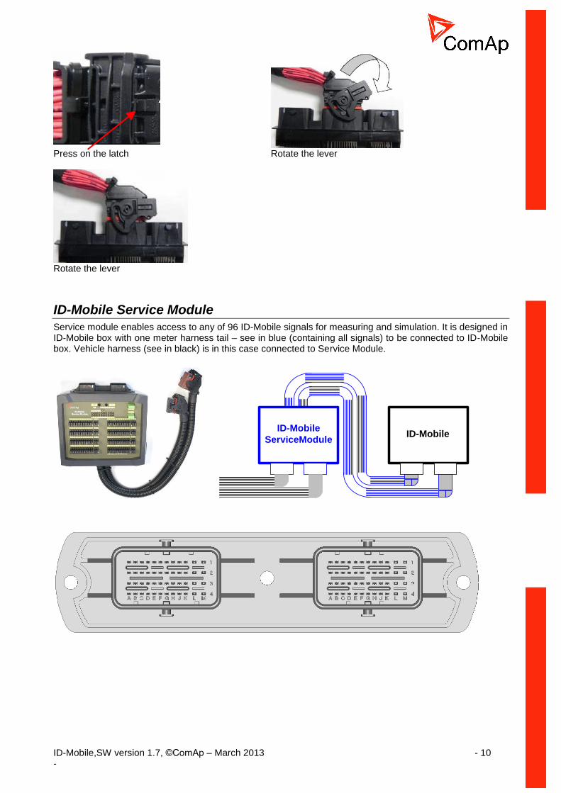
Press on the latch Rotate the lever
Rotate the lever
ID-Mobile Service Module
Service module enables access to any of 96 ID-Mobile signals for measuring and simulation. It is designed in ID-Mobile box with one meter harness tail – see in blue (containing all signals) to be connected to ID-Mobile box. Vehicle harness (see in black) is in this case connected to Service Module.

ID-Mobile,SW version 1.7, ©ComAp – March 2013 - 11 -
Terminals
Pins (numbering) location (four rows per 12 pins each, power pins are in bold)
Left side male connector Right side male connector
1 2 3 4 5 6 7 8 9 10 11 12 1 49 50 51 52 53 54 55 56 57 58 89 60
13 14 15 16 17 18 19 20 21 22 23 24 2 61 62 63 64 65 66 67 68 69 70 71 72
25 26 27 28 29 30 31 32 33 34 35 36 3 73 74 75 76 77 78 79 80 81 82 83 84
37 38 39 40 41 42 43 44 45 46 47 48 4 85 86 87 88 89 90 91 92 93 94 95 96
Bottom side of box
A B C D E F G H J K L M A B C D E F G H J K L M
Left side connector - Pins function 4 3 2 1
37 AIN9 / AOUT1 25 AIN 1 A 13 BOUT 8 1 BOUT 9
38 AIN 10/AOUT 2 26 AIN 2 B 14 BOUT 7 2 BOUT 10
39 AIN 11/AOUT 3 27 AIN 3 C 15 BOUT 6 3 BOUT 11
40 AIN 12/AOUT 4 28 AIN 4 D 16 BOUT 5 4 BOUT 12
41 AIN 13/AOUT 5 29 AIN 5 E 17 BOUT 1 5 BOUT 13
42 AIN 14/AOUT 6 30 AIN 6 F 18 BOUT 2 6 BOUT 14
43 AIN 15/AOUT 7 31 AIN 7 G 19 BOUT 3 7 BOUT 15
44 AIN 16/AOUT 8 32 AIN 8 H 20 BOUT 4 8 BOUT 16
45 n.c. 33 AIN COM J 21 +5V 9 IM 2 IN
46 IN/OUT-COM 34 BINserv K 22 +10V 10 IM 2 SUP
47 VBOUT 13-16+ BAT PLUS
35 BOUTserv L 23 VBOUT5-8+ BAT PLUS
11 VBOUT 9-12+ BAT PLUS
48 VBOUT 13-16- BAT MINUS
36 BAT MINUS
M 24 VBOUT1-4+ BAT PLUS
12 VBOUT 9-12- BAT MINUS
Right side connector - Pins function 4 3 2 1
85 RS485A 73 RPM 4- A 61 BIN 9 49 BIN 1
86 RS-COM 74 RPM 4+ B 62 BIN 10 50 BIN 2
87 RS485B 75 RPM 3- C 63 BIN 11 51 BIN 3
88 CAN1H 76 RPM 3+ D 64 BIN 12 52 BIN 4
89 CAN1-COM 77 RPM 2- E 65 BIN 13 53 BIN 5
90 CAN1L 78 RPM 2+ F 66 BIN 14 54 BIN 6
91 CAN2H 79 RPM 1- G 67 BIN 15 55 BIN 7
92 CAN2-COM 80 RPM 1+ H 68 BIN 16 56 BIN 8
93 CAN2L 81 IM 1 IN J 69 BIN 9-16 COM 57 BIN 1-8 COM
94 D+ 82 IM 1 SUP K 70 GOV 58 n.c.
95 BAT PLUS 83 BAT PLUS L 71 BAT PLUS 59 BAT PLUS
96 BAT MINUS 84 BAT MINUS M 72 BAT MINUS 60 BAT MINUS

ID-Mobile,SW version 1.7, ©ComAp – March 2013 - 12 -
Physical input/output structure
BIN1
BIN2
BIN3
BIN4
BIN5
BIN6
BIN7
BIN8
49
50
51
52
53
54
55
56
57BIN-COM
Bin
ary
in
pu
ts
AIN1
AIN2
AIN3
AIN4
AIN5
AIN6
AIN7
AIN8
25
26
27
28
29
30
31
32
33COM
An
alo
g in
pu
ts
BOUT5
BOUT6
BOUT7
BOUT8
16
15
14
13
23 SUP5-8
Bin
Ou
ts
Hi-S
ide
sw
itch
BOUT1
BOUT2
BOUT3
BOUT4
17
18
19
20
Bin
Ou
ts
Hi-S
ide
sw
itch
24 SUP1-4
BIN9
BIN10
BIN11
BIN12
61
62
63
64
65
66
67
68
69BIN-COM
Bin
ary
in
pu
ts
BW
BW
BW
BWBIN13
BIN14
BIN15
BIN16
RPM1A
RPM1B
RPM2A
RPM2B
RPM3A
RPM3B
RPM4A
RPM4B
79
80
77
78
75
76
73
74
Fre
qu
en
cy / R
PM
inp
uts
+10V Ref
+5V Ref
22
21 Re
f
vo
lta
ge VBATT+
VBATT-
83,95
84, 96
Po
we
r
Su
pp
ly
RS485-A
COM
RS485-B
85
86
87
RS
48
5BOUT9
BOUT10
BOUT11
BOUT12
1
2
3
4
12 -SUP 9-12
11 +SUP 9-12B
inO
uts
PW
M, B
rid
ge
AIN9 / AOUT1 37
AIN10 / AOUT238
39
40
41
42
43
44
An
alo
g
inp
uts
/ o
utp
uts AIN11 / AOUT3
AIN12 / AOUT4
AIN13 / AOUT5
AIN14 / AOUT6
AIN15 / AOUT7
AIN16 / AOUT8
70 GOV OUT
46 COM
IM 1 SUP
IM1 IN
IM2 SUP
IM 2 IN
82
81
xx
10
9
xx Imp
uls
e in
pu
ts
BAT-
BAT-
BOUT13
BOUT14
BOUT15
BOUT16
5
6
7
8
47 +SUP 13-16
48 -SUP 13-16
Bin
Ou
ts
PW
M, B
rid
ge
,
CAN1-H
COM
CAN1-L
CA
N1
bu
s
88
89
90
CAN2-H
COM
CA
N2
bu
s
CAN2-L
91
92
93

ID-Mobile,SW version 1.7, ©ComAp – March 2013 - 13 -
Binary inputs BIN1 to BIN16
Binary inputs BIN1 to BIN8 can be active to minus or plus of power supply. It can be selected by jumper “BI1 – BI8 polarity” and corresponding setpoint JumperBIN1to8. Activate to BATT+ :
BIN1
BIN2
BIN3
BIN4
BIN5
BIN6
BIN7
BIN8
49
50
51
52
53
54
55
56B
inar
y in
pu
ts
+-8 – 36 VDC
BAT PLUS 95
BAT MINUS 96
Activate to BATT- :
BIN1
BIN2
BIN3
BIN4
BIN5
BIN6
BIN7
BIN8
49
50
51
52
53
54
55
56
57BIN 1-8 COM
Bin
ary
inp
uts
+-8 – 36 VDC
BAT PLUS 95
BAT MINUS 96
Binary inputs BIN9 to BIN16 can be active to minus of power supply only. BIN13 – BIN16 has implemented functionality Broken wire detection (BW). For correct behavior between BIN and COM has to be connected 10 kΩ resistor.
BIN9
BIN10
BIN11
BIN12
61
62
63
64
65
66
67
68
69BIN 9-16 COM
Bin
ary
inp
uts
BW
BW
BW
BWBIN13
BIN14
BIN15
BIN16
+-8 – 36 VDC
BAT PLUS 95
BAT MINUS 96

ID-Mobile,SW version 1.7, ©ComAp – March 2013 - 14 -
Binary outputs BO1 to BO8
BO1 to BO8 are single high-side switches where the load is connected against minus power supply terminal.
UBO1-4
BOUT1
BOUT2
BOUT3
BOUT4
20
19
18
17
24
UBO5-8
BOUT5
BOUT6
BOUT7
BOUT8
16
15
14
13
23
+-
Maximal output current continuous 2A. Maximal short term current 3A. When not all channels are used it is recommended to use gaps between channels (e.g. BO1, BO3, BO5, BO7) It is possible to invert channels logic in DriveConfig. PWM is not available on BOUT1 to BOUT8. Close corresponding jumper to avoid BW detection of unused outputs BO1 to BO8. BO 1/2 Fail is indicated in the case of BW on BO1 or BO2 (collected indication for 1-2, 3-4, 5-6, 7-8 output couples).
Reason of BOUT1 – BOUT8 disconnection (block) and error indication – see Binary outputs BO 1/2 to BO 7/8 Fail. - Short circuit (over 8 Amps) between BOUT 1-2; BOUT 3-4; BOUT 5-6; BOUT 7-8; - Short circuit (over 8 Amps) of any BOUT1-8 to BAT MINUS - Short circuit (over 8 Amps) of any BOUT1-8 to BAT PLUS - Overheat (over 150 °C on chip) and Undervoltage below 5,3V of chip supply. - Broken wire (just indication)
Binary outputs BO9 to BO16
There is one control signal for each binary channel. The load is closed or not depends if load is wired to plus or minus of power supply (i.e. as Hi-side or Low-side switch). One of two switches on each Binary output is closed and one opened in any operational case. Both switches are opened only when on-chip (e.g. overcurrent or overheat) protection is activated. Binary outputs BO9 to BO16 can be configured many different ways:
+-
BOUT 9
BOUT 10
BOUT 11
BOUT 12
UBO9-12+
BO9-12-
1
2
3
4
11
12
WARNING! It is not recommended to use High-Side switches for activation of Emergency or admission type of actuators (e.g. gas valves, fuel valves etc.).
High-Side switches. Wiring example: BOUT9 and BOUT11 are closed BOUT10 and BOUT12 are opened Configuration: Property–Output type = BO Property–Inverted = YES or NO High-Side PWM. Configuration: Property–Output type = PWM Property–Output curve = … create in Expert mode-User curves-Output curves Or use linear curve

ID-Mobile,SW version 1.7, ©ComAp – March 2013 - 15 -
Example 1 of Output curve for PWM on Binary output (see DriveConfig-User curves–Output curves)
Primary: source value Converted: output value
Reason of BOUT9 – BOUT16 disconnection (block) and error indication – see Binary outputs BO 9/10 to BO 15/16 Fail. - Short circuit (over 8 Amps) between BOUT 9-10; BOUT 11-12; BOUT 13-14; BOUT 15-16; - Short circuit (over 8 Amps) of any BOUT9-16 to BAT MINUS - Short circuit (over 8 Amps) of any BOUT9-16 to BAT PLUS - Overheat (over 150 °C on chip) and Undervoltage below 5,3V of chip supply.
+-
BOUT 9
BOUT 10
BOUT 11
BOUT 12
UBO9-12+
BO9-12-
1
2
3
4
11
12
Low-Side switches. Wiring example: BOUT9 and BOUT11 are opened BOUT10 and BOUT12 are closed. Configuration: Property–Output type = BO Property–Inverted = YES or NO Low-Side PWM. Configuration: Property–Output type = PWM Property–Inverted = YES or NO

ID-Mobile,SW version 1.7, ©ComAp – March 2013 - 16 -
+-
BOUT 9
BOUT 10
BOUT 11
BOUT 12
UBO9-12+
BO9-12-
1
2
3
4
11
12
Bridge outputs.
Wiring example: Two reversible actuators.
+-
BOUT 9
BOUT 10
BOUT 11
BOUT 12
UBO9-12+
BO9-12-
1
2
3
4
11
12
Bridge outputs. Combined: One reversible actuator and two relays.
+-
BOUT 9
BOUT 10
BOUT 11
BOUT 12
UBO9-12+
BO9-12-
1
2
3
4
11
12
DC motor control.
The same structure can be used for BOUT 13 – BOUT16
Name Pin Configuration as
UBO9-12+ 11 Positive power supply for BO9-12
BOUT9 1 BO PWM BRIDGE DC Motor
BOUT10 2 BO PWM
BOUT11 3 BO PWM BRIDGE
BOUT12 4 BO PWM
BO9-12- 12 Negative power supply for BO9-12
UBO13-16+ 47 Positive power supply for BO13-16
BOUT13 5 BO PWM BRIDGE DC Motor
BOUT14 6 BO PWM
BOUT15 7 BO PWM BRIDGE
BOUT16 8 BO PWM
BO13-16- 48 Negative power supply for BO13-16

ID-Mobile,SW version 1.7, ©ComAp – March 2013 - 17 -
RPM Inputs
RPM1A
RPM1B
RPM2A
RPM2B
RPM3A
RPM3B
RPM4A
RPM4B
79
80
77
78
75
76
73
74
Fre
qu
en
cy / R
PM
inp
uts
Use magnetic pickups.
RPM1
RPM2
RPM3
RPM4
Engine Speed
LAI
Engine RPM(value)
ID-Mobile
State Machine
Default configuration
LAI = Logical Analog Input Engine RPM = value default configured to RPM1.
Indication of RPM2 and RPM3 in DriveMonitor-2.5 Indication of Engine RPM (RPM1 in default).
Impulse inputs
+IM1 SUP (+24VDC)
IM 1 IN
IM 2 IN
82
81
xx
10
9
xx Imp
uls
e in
pu
ts
BAT-
BAT-
+IM 2 SUP (+24VDC)
Use active NPN open collector sensors.
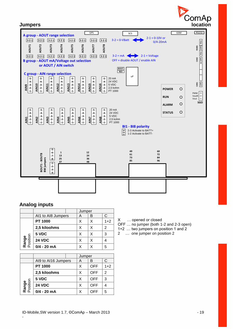
Jumpers – hardware configuration
Prior to configuration procedure the hardware jumpers has to be connected. See below available jumpers groups. NOTE: Take care of correct jumper setting to avoid repeated ID Mobile box opening. A GROUP AOUT1-AOUT8 range switch B GROUP AOUT1-AOUT8 function and On/Off switch C GROUP AIN1 – AIN16 range switch BOUT1-8 Corresponding jumper has to be closed when BOUT is not used (wired) to avoid
BW (broken wire) message. CAN1, CAN2, RS485 Terminating 120 ohms resistors

ID-Mobile,SW version 1.7, ©ComAp – March 2013 - 18 -
SGO Speed governor (analog) output selection BOOT System booting BIN1 to BIN8 input polarity
BIN1 to BIN8 input polarity
BOUT BOUT broken wire detection blocking for not used outputs. NOTE: Analog outputs AOUT1–8 and analog inputs AIN 9-16 share connector pins 37 to 44 – see table below. Each pin from this group can be used or for AIN or for AOUT (not both). To use any analog input AIN9-16 the corresponding B Group jumper has to be disconnected and corresponding AOUT can not be used. Analog inputs AIN1-AIN8 can be used in any case - do not depend on AOUT1-AOUT8 configuration.
PIN Function
37 AOUT1 AIN9
38 AOUT2 AIN10
39 AOUT3 AIN11
40 AOUT4 AIN12
41 AOUT5 AIN13
42 AOUT6 AIN14
43 AOUT7 AIN15
44 AOUT8 AIN16
Configuration examples
Function A GROUP B GROUP C GROUP
AOUT: 0 - 24VBatt 3-2 2-1 OFF
AOUT: 0 - 10VDC 2-1 2-1 OFF
AOUT: 0 – 20 mA 2-1 3-2 OFF
AIN: 20 mA X OFF 5
AIN: 5 VDC X OFF 4
AIN: 24 VDC X OFF 3
AIN: 2,5 kOhm X OFF 2
AIN: PT1000 X OFF 1+2
Note: X … opened or closed NOTE: X … opened or closed CAUTION! To use any analog output AOUT1-8 the corresponding C Group jumper has to be disconnected. E.g. for AOUT1 has to be disconnected all C Group jumper AIN9. Connected jumper has influence on AOUT.
ID-Mobile,SW version 1.7, ©ComAp – March 2013 - 19 -
Jumpers location
uP
AO
UT1
AO
UT2
AO
UT3
AO
UT4
AO
UT5
AO
UT6
AO
UT7
AO
UT8
AIN
1
AIN
2
AIN
3
AIN
4
AIN
5
AIN
6
AIN
7
AIN
8
AIN
9
AIN
10
AIN
11
AIN
12
AIN
13
AIN
14
AIN
15
AIN
16
1 1213 2425 3637 48
49 6061 7273 8485 96
3-2-1 3-2-1 3-2-1 3-2-1 3-2-13-2-1 3-2-1 3-2-1
3-2-1 3-2-1 3-2-1 3-2-1 3-2-13-2-1 3-2-1 3-2-1
-5--4--3--2--1-
-5--4--3--2--1-
-5--4--3--2--1-
-5--4--3--2--1-
-5--4--3--2--1-
-5--4--3--2--1-
-5--4--3--2--1-
-5--4--3--2--1-
-5--4--3--2--1-
-5--4--3--2--1-
-5--4--3--2--1-
-5--4--3--2--1-
-5--4--3--2--1-
-5--4--3--2--1-
-5--4--3--2--1-
-5--4--3--2--1-
BOOT
RES
-3--2--1-
PWMVoutRVout
SGO
20 mA
24 VDC
5 VDC
2,5 kohm
PT 1000
C group - AIN range selection
B group - AOUT mA/Voltage out selection or AOUT / AIN switch
A group - AOUT range selection3-2 = 0-VBatt
2-1 = 0-10V or 0/4-20mA
3-2 = mA 2-1 = Voltage
-1--2--3--4-B
OU
T1 -
BO
UT8
B
W ju
mp
ers
-5--6--7--8-
OFF = disable AOUT / enable AIN
3-2
-1
2-3 Activate to BATT+
1-2 Activate to BATT-
BI1 - BI8 polarity
GSMGPS SCS RS232
POWER
RUN
ALARM
STATUS20 mA
24 VDC
5 VDC
2,5 kohm
PT 1000
12
0R
12
0R
-Bia
s+
Bia
s
RS4
85
12
0R
CA
N1
CA
N2
Analog inputs
X … opened or closed OFF … no jumper (both 1-2 and 2-3 open) 1+2 … two jumpers on position 1 and 2 2 … one jumper on position 2
Jumper
AI9 to AI16 Jumpers A B C
Ran
ge
Positio
n
PT 1000 X OFF 1+2
2,5 kiloohms X OFF 2
5 VDC X OFF 3
24 VDC X OFF 4
0/4 - 20 mA X OFF 5
Jumper
AI1 to AI8 Jumpers A B C
Ran
ge
Positio
n
PT 1000 X X 1+2
2,5 kiloohms X X 2
5 VDC X X 3
24 VDC X X 4
0/4 - 20 mA X X 5

ID-Mobile,SW version 1.7, ©ComAp – March 2013 - 20 -
AIN1
AIN2
AIN3
AIN4
AIN5
AIN6
AIN7
AIN8
25
26
27
28
29
30
31
32
33COM
An
alo
g in
pu
ts
Example of resistive measuring. Max sensor resistance = 2500 ohms. Jumpers in position: 1+2 for PT1000 2 for 0 to 2500 ohms range Sensors from this group have to be connected directly to COM terminal 33.
AIN1
AIN2
AIN3
AIN4
AIN5
AIN6
AIN7
AIN8
25
26
27
28
29
30
31
32
33COM
An
alo
g in
pu
ts
+-
Fuse
+24VBAT
Example of 0/4-20mA current measuring. Sensors from this group have to be connected directly to COM terminal 33.
+10V Ref
+5V Ref
22
21
Re
f
vo
lta
ge
AIN1
AIN2
AIN3
AIN4
AIN5
AIN6
AIN7
AIN8
25
26
27
28
29
30
31
32
33COM
An
alo
g in
pu
ts
200 mA
Example of 5V inputs measuring. Sensors from this group have to be connected directly to COM terminal 33.
NOTE: To use analog input AIN9-AIN16 the corresponding B group jumper. – MUST be disconnected!!!
Analog outputs
X … opened or closed 1-2 … jumper on position 1- 2 OFF … no jumper (both 1-2 and 2-3 open)
CAUTION! To use any analog output AOUT1-8 the corresponding C Group jumper has to be disconnected. E.g. for AOUT1 has to be disconnected all C Group jumper AIN9. Connected jumper has influence on AOUT. NOTE: Restriction for HW version 1.2 and lower: Power supply must be more than 18VDC to achieve full range of AOUT
AOUT1 to AOUT8 Jumpers A B C
Ran
ge
Positio
n 0 to 10V 1-2
1-2 OFF
0 to +VBat(*) 2-3 OFF
0/4 to 20 mA 1-2 2-3 OFF

ID-Mobile,SW version 1.7, ©ComAp – March 2013 - 21 -
CAUTION! Power supply should be not less than 10V if output 10 V must be achieved NOTE: AOUT range value is in mV i.e. 10000 = 10,000Volts Analog output is disconnected when corresponding B GROUP jumper is removed.
0 to 10,000V or 0/4 to 20mA
AIN10 / AOUT238
39
40
41
42
43
44
An
alo
g
inp
uts
/ o
utp
uts
AIN11 / AOUT3
AIN12 / AOUT4
AIN13 / AOUT5
AIN14 / AOUT6
AIN15 / AOUT7
AIN16 / AOUT8
70 GOV OUT
AIN9 / AOUT137
46 COM
General example of Analog outputs wiring. Jumpers (A, B group) selectable range 0 to 10,000V (A=2-1 B=2-1) or 0 to – Vbatt (A=3-2 B=2-1) or 0/4 to 20 mA. (A=2-1 B=3-2)
AIN/AOUT terminals group is variable. Different combination of AIN and AOUTS can be configured. NOTE: To use analog input AIN9-AIN16 the corresponding B group jumper. – MUST be disconnected!!!
mA
V
20 mA
5 VDC
24 VDC
2,5 kohm
PT 1000
C group
B group
A group1 310V VBAT
1
1
3
3
pro
ce
sso
r
ID-Mobile box
5
AIN
AOUT
Speed governor output GOV OUT (terminal 70) is engine governor analog interface selectable by SGO jumper between:
0 to 10,000V – position 1
0 to 10,000V via 10kiloohms resistor – position 2
PWM – position 3
GOV OUT is not configurable by DriveConfig.

ID-Mobile,SW version 1.7, ©ComAp – March 2013 - 22 -
Analog outputs limits calculator
Available for Analog outputs configuration.
Output value Meaning Configuration Valid for
0 0 mA 0 mV 0% PWM
0/4 to 20 mA 0 to 10 V PWM
AOUT1 to AOUT8 AOUT1 to AOUT8 BOUT9 to BOUT16
10000 20 mA 10,000 V 100% PWM
0/4 to 20 mA 0 to 10 V PWM
AOUT1 to AOUT8 AOUT1 to AOUT8 BOUT9 to BOUT16
Low and High limit explanation
Lo
w L
imit
Hig
h L
imit
Physical
output
20mA or 10V or 100%PWM
0mA or 0V or 0%PWM
Source value
Ou
tpu
t v
alu
e
Transformed output value indication The „&” prefix is used with Source value name for output value indication in corresponding analog inputs.
Analog outputs
limits calculatorSource value
ID-AIN5
Converter to mA or
Volts or PWM
Physical
output&ID-AIN5

ID-Mobile,SW version 1.7, ©ComAp – March 2013 - 23 -
PWM output on BO9 up to BO16
Dither function is intended to avoid an unpredictable behavior of hydraulic proportional valves caused by hysteresis and stiction. Dither is a rapid, small movement of the spool around desire position which eliminates the stiction and enables more accurate moving of the valve. Typical use – Proportional hydraulic valves. Setting of BO PWM and Dither function is available on Binary Output BO9 up to BO16
Dither function is active only if PWM output type is configured
PROPERTY VALUE DETAILS
OUTPUT TYPE BO Standard Binary Output
PWM Pulse With Modulation (PWM) output
NAME Text Title of the BOUT – maximum 14 charts
SOURCE According to Input Source for output. See list of sources
INVERTED Yes Inversion (negation) of BO signal is active
No Inversion (negation) of BO signal is active
OUTPUT CURVE According to user curves
If no user curve is created the output is linear
LO LIMIT 0% 0% of PWM conforms to physical value (e.g.0%PWM = 0V) See picture below
HI LIMIT 100% 100% of PWM conforms to physical value (e.g.100%PWM = 10V) See picture below

ID-Mobile,SW version 1.7, ©ComAp – March 2013 - 24 -
Plug in modules
GPS Module
GPS module enables function of exact controller location as well as protection against unwanted manipulation of the controller (GeoFencing). After installation of the module to the controller is for the basic function no other setpoints required. For setting of GeoFencing see SSeettppooiinnttss // PPoossiittiioonn NOTE: Recommended Antenna Order code: GSM/GPRS ANTENNA
NOTE: For further details how to install the module see GPS Assembling document in supplement.
GSM and GPRS Module There are two plug-in modules available:
1. ID-Mobile GSM 2. ID-Mobile GPRS
Both modules have two operation modes: 1. Standard GSM mode CSD (Circuit Switch Data) 2. GPRS mode
Selection of the mode is done by setpoint (See SSeettppooiinnttss// AAccttiivvee ccaallll//SSMMSS
//MMooddeemm).
NOTE: Recommended Antenna Order code: GSM/GPRS ANTENNA
Overview of supported modes and functions:
CAUTION! For support of WebSupervisor and AirGate chose the ID-Mobile GPRS plug-in module. NOTE: Proper function of GPRS/GPS connection depends significantly to cell network provider. Be sure your provider supports data transfer CAUTION! Disable the PIN code on the SIM card prior applying in ID-Mobile / ID-Mobile Logger NOTE: For further details how to install the module see GSM Assembling document in supplement.
MODULE TYPE OPERATION MODE DESCRIPTION SUPPORTS
ID-MOBILE GSM
TELIT CSD GSM mode CSD (Circuit Switch Data) Alarm SMS Drive Monitor (via modem connection)
TELIT GPRS Customized interface For special custom application only
ID-MOBILE GPRS
SIMCOM CSD Standard GSM mode CSD (Circuit Switch Data) Alarm SMS Drive Monitor via modem connection
SIMCIM GPRS GPRS network – enables connection via AirGate
Alarm SMS AirGate Drive Monitor (via AirGate) WebSupervisor

ID-Mobile,SW version 1.7, ©ComAp – March 2013 - 25 -
External displays
ID-Display D13-V
Color 6.5“ VGA640x480 display 5+1 buttons +Jog-Dial Rugged plastic ABS case with Deutsch connector Anti-reflection real glass front cover Operating temperature: -30 + 85°C IP 65 Vibrations: 5G CAN interface Needs dedicated configuration
Interface for 2 cameras optional Power supply 9 – 32 VDC
CAN2-H
COM
91
92
93
CA
N2
bu
s
CAN2-L
+-
VBATT+
VBATT-
83,95
84, 96
Po
we
r
Su
pp
ly
CAN 1 L
CAN 1 H 4
5
0VBatt
+24VBatt 12
1
Light sw.
6Ignition sw.
7
Fuse 5A
120 ohm
+24VBAT
ID Mobile Logger
ID-Display D13-V
+ SUPPLY 11
- SUPPLY 10
VideoIn1 9
VideoIn2 8
NOTE: Ignition switch must be activated for correct ID-Display D13-V function.
Recommended camera wiring
Bosch Camera CAM-PRO/10 terminals Bodas DI3
3, 4 10
5 9
6 11
COMAP ORDER CODE
ID-Display D13-V

ID-Mobile,SW version 1.7, ©ComAp – March 2013 - 26 -
ID-Display 2600
Monochrome 4.25“ FTSN display 160 x 128 pixel 5 buttons Rugged plastic ABS case with Deutsch connector Operating temperature: -25 + 75°C (Optional -40 + 75°C version) IP 67 Power supply: 10 – 32 VCD CAN interface Needs dedicated configuration
CAN2-H
COM
91
92
93
CA
N2
bu
s
CAN2-L
+-
VBATT+
VBATT-
83,95
84, 96
Po
we
r
Su
pp
ly
CAN L
CAN H 8
7
0VBatt
+24VBatt 2
1
Fuse 5A
120 ohm
+24VBAT
ID-Display 2600
ID Mobile Logger
COMAP ORDER CODE
ID-Display 2600

ID-Mobile,SW version 1.7, ©ComAp – March 2013 - 27 -
InteliVision 8
8” color TFT display - 800x600 pixels Operating temperature: -20 + 75°C Front IP65 / Rear IP 20 CAN bus interface Plug and Play structure following controller configuration Power supply 8 – 36 VDC NOTE:
Screen can be customized with ScreenEditor (SW application included in DriveConfig)
InteliVision 5 - CAN 5" color TFT display - 320 × 240 pixels Operating temperature: -20 + 75°C Protection IP 65 CAN bus interface Plug and Play structure following controller configuration Power supply: 8 -36 VDC
Communication lines
RS485
RS485-A
COM
RS485-B
85
86
87
RS
48
5
RS485 / USB
converter
USB
USB
DriveConfigDriveMonitorWinScope
ID-Mobile / ID-Mobile-Logger RS485 interface is dedicated to:
PC interface for communication with DriveMonitor, DriveConfig and other SW.
MODBUS communication interface
COMMUNICATIONS ID-MOBILE-LOGGER
Direct connection
USB
RS485
RS232
CAN1
CAN2
GSM 1)
GPRS 1)
GPS 1)
1) Plug-in module required

ID-Mobile,SW version 1.7, ©ComAp – March 2013 - 28 -
CAN1
Interface for:
ECU (Engine Control Unit) – J1939 or KWP2000 protocols.
I-CB (Inteli-Communication Bridge)
IGS-PTM (I/O Extension module - 8BI, 8BO, 4AI, 1AO)
IS-AIN (Analog input extension module - 8 AI)
IS-BIN (Binary Inputs extension module - 16BI, 8BO)
CAN2
ID-Mobile / ID-Mobile-Logger CAN2 interface is dedicated to:
external displays (see External displays )
ID-Mobile Slave unit
I-LB, I-LB+, (Inteli – Local Bridge communication module)
CAN bus connection rules Can bus line must be connected in series, from one unit to another (no star, no cable stubs, no braches) and
both ends must be terminated with 120 resistor.
There are internal 120 resistors on ID-Mobile / ID-Mobile-Logger motherboard available:
NOTE: All controllers must be adjusted to the same CAN bus mode. Default mode for CAN1 and CAN2 bus in ID-Mobile / ID-Mobile-Logger is 250kBd. The limitation of line for the default speed is 200m maximum.
RS485 120resistor Jumper
CAN1 resistor Jumper
CAN2 resistor Jumper
RS485 -BIAS resistor Jumper
RS485 +BIAS resistor Jumper

ID-Mobile,SW version 1.7, ©ComAp – March 2013 - 29 -
Modules
Following items is possible to configure in DriveConfig – Modules
Module No
ID-Mobile [1/1] It is obligatory item.
Binary Inputs module [x/8] Use for extension modules IGS-PTM, IS-BIN16/8 and ICB.
Binary Outputs module [x/8] Use for extension modules IGS-PTM, IS-BIN16/8, IGL-RA15 and ICB.
Analog Inputs module [x/4] Use for extension modules IGS-PTM, IS-AIN and ICB.
Analog Outputs module [x/4] Use for extension modules IGS-PTM, I-AOUT8 and ICB.
Shared Binary inputs [x/4] Binary data transfer between ID-Mobile Master and Slave.
Shared Binary outputs [x/4] Binary data transfer between ID-Mobile Master and Slave.
Shared Analog inputs [x/4] Binary data transfer between ID-Mobile Master and Slave.
Shared Analog outputs [x/4] Binary data transfer between ID-Mobile Master and Slave.
ECU [x/1] Item for J1939 electronic engines support.
ICB module [x/1] Item for other than J1939 electronic engines support.
Virtual Binary Outputs [x/4] For data transfer via Modbus – e.g. separate fault indications.
PLC [x/1] Select this item before PLC functions configuration.
ID-Mobile Master - Slave concept
ID-Mobile Master: Master module i.e. standard ID-Mobile hardware is dedicated as single unit. ID-Mobile Slave: Slave module can be used to increase number of I/O and PLC functions and/or transfer signals from machine moving part just via CAN bus to reduce wiring. ID-Mobile Slave is equal to Master hardware and its function is blocked when used as single unit - without Master. When ID-Mobile Slave works as single unit:
- “Sd MasterCommErr” is indicated in Alarm list and in History - All Analog inputs are indicated as ##### invalid value - All Binary inputs are indicated as # invalid value
Master and Slave can share values via “Shared Binary and Analog I/Os” via CAN2. There is one common ID-Mobile-1.1 (or higher) firmware for both. Ordering code is ID-Mobile Slave.
Engine
ID-Mobile Master
Vehical Base Part
ID-Mobile Slave
Moving Part

ID-Mobile,SW version 1.7, ©ComAp – March 2013 - 30 -
Binary Inputs
Any InteliDrive controller binary input can be configured as “function” and/or “protection”. Following chapter contains Logical binary inputs list (functions list) that can be configured to any physical input. NOTE: Minimal input pulse duration is 120 ms to be detected as valid (binary inputs sampling rate is 100 ms). Adjustable delay can be configured to any binary input when is used as a protection: Standard = 0,5 sec or one of BinInp delay 1, 2, 3 that can be adjusted by corresponding Setpoint BinInp delay 1, 2, 3.
BI delay configuration
Setpoint
Standard (0,5s)
BinInp delay 1 BinInp delay 1
BinInp delay 2 BinInp delay 2
BinInp delay 3 BinInp delay 3
See setpoints BinInp delay 1 [s] etc…
Force Block
Active input blocks protections that are configured as (in DriveConfig) as Property:Prot.block type= Force Block. Corresponding setpoint is ForceBlock del.
Fault Reset Binary input for Alarm acknowledge (edge sensing) has the same function as controller front panel button Fault reset. Hint: There is separate acknowledge for ECU Alarms – see Binary input ECU FltReset.
Horn Reset
Binary input Horn reset is edge sensing signal.
Remote OFF Controller is switched to OFF mode if input is closed and back to previous mode after is opened. NOTE: Remote OFF will switch controller to OFF mode even if the Access code or Remote lock is active or Controller mode is password protected.
ECUComFailBlck Active input blocks ECU communication fail. Function can be used e.g. when ECU is switched off after engine stop.
Emergency Stop Engine Shut down activation. It is recommended to configure Emergency stop as normally closed contact from safety reason (this configuration is in default aid archive).

ID-Mobile,SW version 1.7, ©ComAp – March 2013 - 31 -
Remote Start
External “edge sensitive” request for engine start. Binary input is active in both SS and AS application. Unsuccessful start is recorded to Alarm list and History. Binary input REMOTE START signal is equivalent to external terminal Start button. Hint: The second edge on Binary input Remote start skips the Idle time when engine is running in Idle state.
Remote Stop
Engine “edge sensitive” stop request. The first edge changes engine state from running to cooling. REMOTE STOP signal is equivalent to external terminal Stop button. NOTE: Binary inputs Remote start, Remote stop are edge (not level) sensitive. Minimal pulse duration to safely detect the edge is at least the 120 ms (binary input sampling rate is 100 ms). The second Remote Stop edge skip the (rest of) cooling.
Back Up Speed1, Back Up Speed2, Back Up Speed3 (AS only) This is back-up for Engine Speed request via failed Analog input. When Engine is Running (or Loaded) and Logical Analog input Requested RPM is not valid (out of range, sensor fail) then Speed Request is set to corresponding Back up Speed value in % (depends on Back Up Speed input). Speed Request = 0% when analog request is out of range and Binary input Back up speed is not active.
Fire Speed (AS only) Running Engine speed is set to Engine params: FireAlarmSpeed if input is active.
Rem On/Off Binary output Close Load is closed/opened by Rem On/Off input edges (toggled) when running engine RPM is over Engine protection: MinLoadSpeed. Binary output Close load can be disconnected from external terminal when Binary input Rem On/Off is closed.
StartBlocking Forces controller NotReady state (=disables engine start).
RunIndication1, RunIndication2, RunIndication3
Binary input can be used for engine running indication e.g. via Oil pressure contact. Active Running indication blocks engine start (to avoid starter damage). Engine running state = RPM > Engine params: Starting RPM or Analog input Oil pressure > Engine params: Starting Poil or Active Binary input Run indication1 or Active Binary input Run indication2 or Active Binary input Run indication3 or Coolant pressure > Engine params: StartPCoolant
Nominal Speed Skips Idle time and switch controller from Idle to running state when closed before Idle time is over.
Emerg. Manual
Controller does not activate binary output Fuel solenoid when engine starter is activated externally.
ID-Mobile,SW version 1.7, ©ComAp – March 2013 - 32 -
Sd Override
Blocks all protections except Overspeed, Emergency stop and configurable SdO protection.
All alarms are detected
Alarms are indicated on the controller display (DriveMonitor) Alarm list screen
Alarms are recorded into History
Enabled Active calls remains active
Controller front panel engine RED LED blinks or lights
Does not influence Sd Override in electronic engine via J1939 NOTE: Shut down override “SdO” protection can be configured to any Analog or Binary input.
Speed Down, Speed Up
The engine Requested RPM is decreased/increased when input is closed. Speed down has higher priority when both Up and Down inputs are active. RPM inc/dec rate is defined by setpoint Engine params: BI Speed ramp. Engine speed can be set by analog input Requested RPM or by BI Speed Up and Down. Following requested RPM initialization is valid when Analog input Requested RPM is not configured. Requested RPM (Idle) = 0. Requested RPM (Running) = 50% for SS (ECU 50%=Nominal RPM). Requested RPM (Running) = 0% for AS. NOTE: Minimal Speed up and Speed down pulse duration is 110ms to be accepted by controller.
ECU FltReset Binary input for ECU Alarm acknowledge (edge sensitive) has the same function as controller front panel Fault reset button (active only in ECU Alarm list). NOTE: Activation of ECU Fault reset will affect InteliDrive only, no reset request is sent to ECU. There is separate acknowledge input for Alarms – see Binary input Fault reset.
BI Droop
This input changes state of logical binary output DROOP SW that can be configured as J1939 output to change ECU mode. Input is active only when Basic setting: Governor mode = EXTERNAL (DROOP when closed).
BI Secondr RPM ( SS only )
This input changes state of logical binary output “Second RPM Sw” that can be configured as J1939 output to change ECU mode. Input is active only when Basic setting: Speed select = BIN.INPUT.
BI Nominal
This input changes state of logical binary output NOMINAL SW that can be configured as J1939 output to change ECU mode. Input is active only when Basic setting: IDLE/NOMINAL = EXTERNAL.
Rem Start/Stop Activates engine start when active in RUN mode and controller ready state. It is not possible to stop engine by panel STOP button and by Binary input Remote stop when Rem start/stop is active. This input can be configured to Binary output Timer active to enable engine automatic start/stop function – see Basic settings / Timer setpoints.

ID-Mobile,SW version 1.7, ©ComAp – March 2013 - 33 -
PrestartOvrd
Prestart override activation skips the Prestart procedure (can be adjusted up to 600sec). Skip Prestart is possible by binary or by repeated press of START button. Example: Finish engine preheating (prelubrication) based on temperature (pressure) limit..
Load Blocking “Load blocking” can block the LBO Close load. Active input is indicated in Alarm list as “Load blocking” message.
PWM9 DISABLE … PWM16 DISABLE Active input disables (switch off) corresponding PWM signal on selected Binary outputs BO9 to BO16.
RS485 Mode Std Active input switches (by rising edge) Basic Settings: RS485 Mode to STANDARD (from other like MODBUS, ECU LINK).
GeoFencingEna Ena/Disables the GeoFencing function (engine block and active alarm) when the Position: GeoFencing = BIN.INPUT.
Home Position Active input (rising edge) moves the actual position into Position: Home Lat and Home Long setpoints.
Clear DayCons
Active input clears the Day Consumption counter.
Clear TripCons
Active input clears the Day Consumption counter.
DisplayMessage1 … DisplayMessage10 Up to 10 message texts are specified in “Display: DisplMessageX” setpoints. Each message setpoint contains the string up to 31 ASCII characters. The message can be displayed in display “Message Display Area” with Date and Time information, when corresponding Logical Binary Input (LBI) DisplMessageXX is activated. Message disappears when LBI is deactivated.
DisplBinary1 … DisplBinary20 The display on screen text status is changed according the corresponding Logical Binary Input (LBI) – DisplBinaryX state.
Example of on display status indication:
LBI Display status
DisplBinary1 = 0 Engine Oil Pressure: Normal
DisplBinary1 = 1 Engine Oil Pressure: Low
DisplayPuls1 … DisplayPuls4 Logical Binary input DisplayPuls1 can be used e.g. for Bodas Control-Camera screens switching based on ID Mobile Binary input or PLC function.
LBI Log 0 Log 1
DisplayPuls1 Control screen Camera screen

ID-Mobile,SW version 1.7, ©ComAp – March 2013 - 34 -
NOTE: Messages and status displaying are available only in specific customer branches with Bodas displays.
BI History
Closed binary input activates one History record.

ID-Mobile,SW version 1.7, ©ComAp – March 2013 - 35 -
Binary outputs
Configure physical Binary outputs in DriveConfig selecting item from Source (e.g. Log Bout) list. Repeated click un-configures selected item.
Source: Log Bout
Horn Binary output for Horn, Buzzer alarm acoustic indication. Output is automatically switched off after Engine protection: Horn timeout. Horn is active unlimited time (until until Horn reset or Fault reset is pressed/activated) when Horn timeout = 0.
Alarm The output closes if any alarm is activated and opens after Fault reset even if the Alarm is still active.
Common Alarm
The output closes if any Wrn, Sd, Cd, Fls, alarm is active and stays closed until all alarms disappear and Fault reset is pressed = output is opened when Alarm list is empty.
Common Wrn
The output closes when any Warning alarm is active. Output opens when all Wrn alarms disappear and Fault reset is pressed (no Wrn alarm in Alarm list).
Common Sd The output closes when any Shut-down alarm is active. Output opens when all Sd alarms disappear and Fault reset is pressed (no Sd alarm in Alarm list).
Common Cd The output closes when any Cool-down alarm is active. Output opens when all Cd alarms disappear and Fault reset is pressed (no Cd alarm in Alarm list).
Common Fls
The output closes when any Sensor fail alarm is active. Output opens when all Fls alarms disappear and Fault reset is pressed (no Fls alarm in Alarm list).
OFF Mode
The output is closed in controller OFF mode.
RUN Mode The output is closed in controller OFF mode.
CPU Ready
CPU indication – output is closed when CPU is ready, opened in Init state.

ID-Mobile,SW version 1.7, ©ComAp – March 2013 - 36 -
Idle/Nominal The output closes during engine start, after Idle time setpoint elapses. The output opens again after Cooling time is finished. The opposite logic output Nominal/Idle is available as well. NOTE: Connect Binary output IDLE / NOMINAL to electronic speed governor to switch the speed: opened = IDLE, closed=RATED.
Starter
Closed output energizes the engine starter.
Stop Solenoid
Output is closed during engine stopping procedure.
Prelubrication Periodic prelubrication function – see Engine params: PrelubrTime and PrelubrPause.
Prestart The output closes prior to the engine start (Preheat, Prelubrication) for Engine params: Prestart time.
Ready To Start
Engine state indication, no active start blocking alarms.
Ready To Load Output closes if the engine is in Running state and can be loaded. Opens in Cooling state. Active only if RPM > MinLoadSpeed.
Engine Running
It activates, when RPM rises above starting RPM and opens when RPM=0.
Ignition
Ignition system activation/deactivation during start stop procedure.
Unload 1 sec (fix) pulse prior to transfer from Running to Cooling state.

ID-Mobile,SW version 1.7, ©ComAp – March 2013 - 37 -
Cooling
Closes in cooling state, opens after engine stop.
Fuel Solenoid Closed output opens the fuel solenoid. Adjustable to DIESEL or GAS.
Cooling Pump The output closes when engine starts and opens AfterCoolTime delayed after stop the engine.
CtrlHeartBeat Indicates correctly running firmware when cycling on/off with 0,5 sec period.
Close Load
Output is closed/opened with rising edge of Binary input Rem On/Off when engine is in Running state and engine RPM is over Engine protection: MinLoadSpeed. Output opens when RPM is below MinLoadSpeed. Close load can be opened remotely (e.g. from DriveMonitor) when Binary input Remote On/Off is closed.
Droop Sw The output is closed when setpoint Basic setting: Governor mode = DROOP or Governor mode = EXTERNAL and corresponding Binary input BI DROOP is closed. This logical output (Source) can be configured to corresponding J1939 output (e.g. Governor Mode in Volvo-IndustrialD12 Aux).
Second RPM Sw (SS only) The output is closed when setpoint Basic setting: Speed select = Secondary or Speed select = BIN.INPUT and corresponding Binary input “BI secondr RPM” is closed. This logical output (Source) can be configured to corresponding J1939 output (e.g. Frequency Select in Volvo-IndustrialD12 Aux) see an example below.
Nominal Sw The output is closed when setpoint Basic setting: Idle/Nominal = NOMINAL or Idle/Nominal = EXTERNAL and corresponding Binary input BI NOMINAL is closed. This logical output (Source) can be configured to corresponding J1939 output (e.g. Idle Speed Select in Volvo-IndustrialD12 Aux).
Stop Pulse
1 sec pulse is generated in the beginning of Stop procedure.
Comm AIN fail Output is closed when any analog extension (IS-AIN, IGS-PTM) unit does not communicate.
Comm BIN fail Output is closed when any analog extension (IS-BIN, IGS-PTM) unit does not communicate.
Comm AOUT fail
Output is closed when any analog extension (IS-AOUT, IGS-PTM) unit does not communicate.
Comm BOUT fail Output is closed when any analog extension (IS-BIN, IGS-PTM) unit does not communicate.

ID-Mobile,SW version 1.7, ©ComAp – March 2013 - 38 -
Nominal/Idle Inverted function to binary output Idle/Nominal. The output closes during engine start, after Idle time setpoint elapses. The output closes again after Cooling time is finished.
Alarm Blink Function is based on Binary output COMMON ALARM - stays closed when any alarm is active (at least one item in Alarm list) and opens for 2 sec when any new Alarm is activated. The first activation is delayed 2 sec. No Fault reset influence when at least one alarm is active. Output opens when Alarm list is empty.
Logical 0 Constant value that can be configured to any input or output - mainly in PLC.
Logical 1
Constant value that can be configured to any input or output - mainly in PLC.
Operational Output closes with binary output Prestart and opens with binary output Cooling pump.
Timer Active
Binary output Timer Active is closed and opened according to Timer setpoints setting. Engine starts and stops when this output is connected (configured) to Binary input Rem start/stop. Timer is active in all controller modes include OFF mode.
Alarm BlinkAct
Alarm indication:
Output starts switching (blinking 0,5/0,5sec from opened or closed state) when any new alarm comes
Output stays closed after Fault reset when any alarm is still active
Output opens after Fault reset when no alarm is active
Common SdO Indication of any active Shut-down Overide protection.
RdyForRemStart
Output is closed when engine is ready for remote start.
ECU PowerRelay The output closes at the beginning of prestart and opens if the engine shall be stopped. This output can be used to indicate when the ECU should be powered up i.e. only while the engine is running. This output also influences evaluation of communication failure with ECU and related FLS alarms from analog inputs read from the ECU. If the output is configured (which means configured on physical binary output or VPIO output), the issuing of communication error is blocked during Prestart and Stopping procedure as shown in the picture.

ID-Mobile,SW version 1.7, ©ComAp – March 2013 - 39 -
NOTE: The output must be configured on physical binary output. It is not enough to configure it as a PLC input for example.
StartButtEcho Output is closed for 1 sec when Start button (e.g. from DriveMonitor is activated).
StopButtEcho
Output is closed for 1 sec when Stop button (e.g. from DriveMonitor is activated).
FltResButtEcho
Output is closed for 1 sec when Fault reset button (e.g. from DriveMonitor is activated).
HrnResButtEcho Output is closed for 1 sec when Horn reset button (e.g. from DriveMonitor is activated).
ClutchButtEcho
Output is closed for 1 sec when Clutch button (e.g. from DriveMonitor is activated).
BO 1/2 Fail
Indication of Binary output 1 and/or Binary output 2 fail or Broken wire detection.
BO 3/4 Fail Indication of Binary output 3 and/or Binary output 4 fail or Broken wire detection.
BO 5/6 Fail
Indication of Binary output 5 and/or Binary output 6 fail or Broken wire detection.
BO 7/8 Fail
Indication of Binary output 7 and/or Binary output 8 fail or Broken wire detection.
Beginning of Prestart
Fuel solenoid deactivation
ECU communication failure alarm blocked
End of Prestart
Engine stopped
t
ECU PwrRelay

ID-Mobile,SW version 1.7, ©ComAp – March 2013 - 40 -
BO 9/10 Fail
Indication of Binary output 9 and/or Binary output 10 fail.
BO 11/12 Fail Indication of Binary output 11 and/or Binary output 12 fail.
BO 13/14 Fail
Indication of Binary output 13 and/or Binary output 14 fail.
BO 15/16 Fail Indication of Binary output 15 and/or Binary output 16 fail. Possible Binary outs fails: - Short circuit (over 8 Amps) between BOUT 1-2; BOUT 3-4; BOUT 5-6; BOUT 7-8; BOUT 9-10; BOUT 11-12; BOUT 13-14; BOUT 15-16; - Short circuit (over 8 Amps) of any BOUT9-16 to BAT MINUS - Short circuit (over 8 Amps) of any BOUT9-16 to BAT PLUS - Overheat (over 150 °C on chip) and Undervoltage below 5,3V of chip supply.
No GPS Signal The output is active when GPS signal from any reason disappear (broken antenna, no GPS signal, GPS module fail) even if the Position: GeoFencing = DISABLED.
Display Key 1 … Display Key 6
ID-Mobile Logical Binary Output (LBO) “Display Key x” is activated when corresponding Bodas button is pressed – see in table below. The first button does not activate the LBO Display Key 1.
LBO Bodas button
No LBO function 1-st “round”
Display Key 2 2-nd
Display Key 3 3-rd
Display Key 4 4-th
Display Key 5 5-th
Display Key 6 6-th
NOTE: Bodas keys procedures are not available in standard Bodas-1.3 firmware, it is dedicated for future customer branches.
User Button 1…5 InteliVision function buttons can be assigned to these five LBOs
RemoteControl1 … RemoteControl8
Remote control outputs can be controlled locally or remotely (via Modem) from DriveMonitor – Remote switch panel.
Source – Prg.states
Programmable states (protections) list. Any item from the following list is activates Alarm list indicarion.

ID-Mobile,SW version 1.7, ©ComAp – March 2013 - 41 -
ECU
ECU communication fail indication.
SHBIN 1…4 Status of shared Binary inputs
SHAIN 1…4
Status of shared Analog inputs
SHBinCfgErr Shared Binary module configuration error – i.e. more than one source was configured (is on the CAN2 bus).
SHAinCfgErr
Shared Analog module configuration error – i.e. more than one source was configured (is on the CAN2 bus).
UnivState 1 … Univ state 7
Universal states 1 to Universal states 7 indication. See Universal states description.
PLC Message 1 … PLC Message 8 Indication of programmable PLC state.
ECU AlarmList
Output is closed when at least one item is in ECU Alarm list.
EcuDiagBlocked Output is closed when Basic setting: ECU diag = DISABLED.
GeoFencing
The output is active (indicates Warning) when the actual position is out of fence.
MasterCommErr
Communication with Master control unit fails.
Emergency Stop Indication of active Emergency stop input.
Overload
Active overload protection activation.
ChrgAlternFail Charger fail detection. D+ output current is limited to cca 300 mA. Guaranteed level for signal Charging OK = 90% of supply voltage. There are three possible conditions for stop engine cranking: Starting RPM, StartingPOil and D+ (when ENABLED). Starter goes off when any of these conditions becames valid.

ID-Mobile,SW version 1.7, ©ComAp – March 2013 - 42 -
Stop Fail Engine stop fail indication. Stop fail: engine does not reach 0 RPM after stop command within Engine params: Stop time.
Overspeed Over speed indication.
Underspeed
Under speed indication.
Pickup Fail Pickup fail indication. Pickup fail: lost of RPM signal in running state (other running indication is active).
Battery Flat ID-MOBILE controller reset during Cranking state.
Battery Volt Indication when battery voltage (ID-MOBILE power supply) is out of Engine protect: Batt <V and Batt >V limits
WrnServiceTime Output is closed when Service time (count down) = 0. NOTE: History record and Alarm list indication is activated as well.
Not Lubricated
The lubrication cycle (PrelubrTime) is not finished after controller Switch on or return from OFF mode.
Start Fail The last start attempt was unsuccessful.
Start Blocking
Indication of active Start - blocking.
Load Blocking Indication of active Load - blocking.

ID-Mobile,SW version 1.7, ©ComAp – March 2013 - 43 -
Logical Analog Inputs list
Engine Speed
Logical RPM value for Engine RPM indication, overspeed protection, engine running and overload detection.
RPM1
RPM2
RPM3
RPM4
Engine Speed
LAI
Engine RPM(value)
ID-MobileState Machine
Default configurationECU-RPM
Oil Press Value can be used as engine Running indication – see Engine Params: Starting POil.
Oil Temp Logical Analog input for value to be displayed on Bodas display.
Coolant Press (AS only) Engine Running indication – see Engine Params: Starting PCoolant.
Coolant Temp
This value is indicated on the first controller screen.
Fuel Level Logical Analog input for value to be displayed on Bodas display.
Requested RPM
Analog Input influences directly Engine Requested RPM register when configured without ramp. In the case of sensor fail (out of range) is Sped request = 0 for AS and 50% (=Nominal RPM) for SS configuration.
Relation between different Speed requests values see in tables below.
SS application
Setpoint: Local Speed 0,0% 50,0% 100,0%
Value: Speed request 0,0% 50,0% 100,0%
Value: SpeedReq RPM 1350 RPM 0,9*Nominal
1500 RPM Nominal
1650 RPM 1,1*Nominal
Output: SGO 0,0V 5,0V 10,0V
AS application
Setpoint: Local Speed 0,0% 50% 100,0%

ID-Mobile,SW version 1.7, ©ComAp – March 2013 - 44 -
Value: Speed request 0,0% 50% 100,0%
Value: SpeedReq RPM 450 RPM 0,3*Nominal
1050 RPM 0,7*Nominal
1650 RPM 1,1*Nominal
Output: SGO 0,0V 5,0V 10,0V
Fuel ConsAct
Logical Analog input to connect external Fuel consumption sensor when no ECU value is available. The sensor output has to be in liters per hour.
Cyl Temp 1 … Cyl Temp 16
Analog inputs for engine Cylinder temperatures measuring and average value calculation.
DisplAnalog1 … DisplAnalog20 Logical Analog Inputs for values to be displayed on Bodas display. NOTE: Specific cases has to be solved by separate Bodas firmware customer branch.
Analog inputs configuration example
for ID-Mobile Starter kit to be displayed on CANtrak-1.1 and Bodas-1.3 with default software.
Analog input Dim Sensor Resolution Sensor range
Bargr. 100%
Logical Function
1. Oil Press Bar 0-2400ohm 0,01 15,00 5,00 Oil Press
2. Cool Temp °C 0-2400ohm 1 350 120 Coolant Temp
3. Oil Temp °C 0-2400ohm 1 350 140 Oil Temp
4. Fuel Level % 0-2400ohm 1 240 100 Fuel Level

ID-Mobile,SW version 1.7, ©ComAp – March 2013 - 45 -
Analog Values (logical outputs)
Any of values from the Source list (see below) can be configured to any ID Mobile AOUT1 to AOUT8 or to ECU/J1939 (virtual) Analog output. Speed Governor Output (GOV OUT) is not configurable. There are following logical analog groups: Basic Values, Engine values, Analog CU, Info and Statistics (and others when IS-AIN8 extension modules are used).
Basic Values
Engine RPM
Actual value can be sourced (depends on configuration) from different sources (RPM1-4, ECU-RPM or physical Analog input).
RPM1, RPM2, RPM3, RPM4 Four separate independent values for any frequency measuring. See – setpoints in Basic setting: Gear Teeth1 to Gear Teeth4.

ID-Mobile,SW version 1.7, ©ComAp – March 2013 - 46 -
Engine Values
SpeedRequest
Internal value of Engine speed request in 0,0 to 100,0 % range that can be sourced from different sources – see drawing below.
Speed Request RPM
Internal value of Engine speed request in RPM range that can be sourced from different sources – see drawing below. NOTE: Different ECU types requires Speed request in % or in RPM range (J1939 - TSC1 frame).
Speed Up
Speed Down
LAI Requested RPM
Speed Request [ % ]
Speed Request RPMEngine params:
BI Speed ramp ThrottlePos
BINARY
INPUTS
ANALOG INPUT
EN
DIS (Accelerator
Pedal Position)
Engine params:
EnLocalSpeedEngine params:
Local speed
Speed Request is set to 0% in the case of sensor fail
and no Back Up Speed selection.
Speed request is automatically
switched to corresponding
ANALOG INPUT when
LAI Requested RPM is
configured on it.
Engine params:
Back Up Speed 1
Back Up Speed 2
Back Up Speed 3
Back Up Speed 1
Back Up Speed 2
Back Up Speed 3
En
gin
e
EC
U
T Cyl Aver, T Cyl Max, T Cyl Min
Engine Cylinder temperature Average, Maximal and Minimal values are calculated from configured Cyl Temp 1 to Cyl Temp 16 Analog values.
Oil Press, Oil Temp, Cool Temp, Fuel Level
Logical values to be displayed on external display (e.g. Bodas or CANtrak).
Statistics values availability
Statistics AOUTs PLC *) History DriveMonitor
Run Hours N Y Y Y
NumSuccStarts Y Y Y Y
NumUnscStarts Y Y Y Y
Service Time Y Y Y Y

ID-Mobile,SW version 1.7, ©ComAp – March 2013 - 47 -
Imp1 N Y Y Y
Imp2 N Y Y Y
DayCons N Y Y Y
TripCons N Y Y Y
*) PLC just via conversion CONVERT function Position values availability
Position AOUTs PLC *) History DriveMonitor
Actual Lat N N Y Y
Actual Long N N Y Y
HomePosDist N Y Y Y
Error Lat Y Y Y Y
Error Long Y Y Y Y
*) PLC just via conversion CONVERT function
Analog outputs availability
Module Number of outputs Note
ID-Mobile AOUT1 to AOUT8
ECU (J1939) 4 (virtual outs) Format depends on ECU
I-AOUT8 4x 8 Analog outputs
Analog outputs configuration
The two limits “Lo limit” and “Hi limit” can be modified in DriveConfig. “Lo limit” corresponds to low Analog output limit i.e. 0V or 0mA output and Hi limit corresponds to full range 10V or 20mA output. Lo limit and Hi limit transfer the full internal analog value range to Analog output range. Following is example of transfer characteristics 0 - 100% to 0 – 20mA and 4 -20mA.
10V or 20 mA
Lo limit Hi limit
0 100
Analog value
in controllerAn
alo
g p
hysic
al o
utp
ut
0V or 0 mA
4 mA
20 mA
Lo limit Hi limit-25
100
Analog CU
Values are shown and titled according to configuration AIN1 – AIN11 and:
Battery Volt
Voltage of the battery (Power source for the controller)
CPU Temp
Processor temperature of the controller

ID-Mobile,SW version 1.7, ©ComAp – March 2013 - 48 -
Binary CU
ID BIN
Binary inputs according to configuration
ID BOUT Binary outputs according to configuration
Log Bout
LogBout 1 …4 Logical binary functions
RemoteControl
Remote control switches status
Info
Engine State
Engine state: Not Running, Ready to Start, Cranking, Cooling etc.
PasswordDecode
This code together with controller S/N is needed if controller password is forgotten.
SW Version SW version in the controller
SW Branch
SW branch identification
Mode ID Current controller mode (OFF, RUN)
Timer Text
Information of timer status
Timer Val
Time to next timer
ECU DiagSource Indication of ECU diagnostic codes source. Typically: None, J1939-DM1, J1939-KWP, J1587-DTC, MODBUS.

ID-Mobile,SW version 1.7, ©ComAp – March 2013 - 49 -
Master/Slave Definition of controller type see: ID-Mobile Master – Slave concept
GSMSignalLevel [%] Indicating quality of GSM signal
GSM Diag Code:
Troubleshooting diagnostic code for ID-Mobile GPRS module
Code Description Code Description
0 OK. No error. 11 SIM card is locked (Possibly PIN code required, PIN needs to be deactivated) or unknown status of SIM locking
1 Not possible to hang up. 12 No GSM signal
2 ID-Mobile-GPRS is switched off 13 Not possible to read the SIM card parameters
3 ID-Mobile-GPRS is switched on 14 GSM modem did not accepted particular initialization command, possibly caused by locked SIM card
4 ID-Mobile-GPRS – error in initialization 15 Unknown modem
5 ID-Mobile-GPRS – not possible to set the APN 16 Bad answer to complement initialization string
6 ID-Mobile-GPRS – not possible to connect to GPRS network
17 Not possible to read GSM signal strength
7 ID-Mobile-GPRS – not possible to retrieve IP address
18 CDMA modem not detected
8 ID-Mobile-GPRS – not accepted DNS IP address
19 No CDMA network
9 Error in modem detection 20 Unsuccessful registration to CDMA network
10 Error in initialization of analog modem 255 Only running communication is needed to indicate
AirGate Diag: AirGate Troubleshooting diagnostic code
AirGate ID: Identification name generated by AirGate server to establish connection with: DriveMonitor InteliMonitor WebSupervisor CAUTION! Connection via AirGate is supported with ID-Mobile GPRS module only (ID-Mobile GSM module does NOT support AirGate)
Modem Status
"-----" - After controller initialization „Trying“ – modem active, trying to establish connection „Ready“ – modem ready, communication with mode"-----" - After controller initialization „Trying“ – modem active, trying to establish connection „Ready“ – modem ready, communication with modem is ok m is ok
Code Description
1 Controller registered, waiting for authorization
2 Not possible to register, controller blacklisted
3 Not possible to register, server has no more capacity
4 Not possible to register, other reason
5 Controller registered and authorized
ID-Mobile,SW version 1.7, ©ComAp – March 2013 - 50 -
LitersPerHour [l/h]
Actual Fuel consumption in liters per hour calculated from IMP1 input and using the PPuullsseessPPeerrLLiitteerr 11 setpoint.
Statistics
NumSuccStarts
Number of total successful starts
NumUnscStarts Number of total un-successful starts
Service Time
Running hours to next service/maintenance period
Position
Error Lat [m]
Latitude error in meters.
Error Long [m]
Longitude error in meters.
MSL Altitude [m] Altitude above sea level in meters.
Ground Speed [km/h]
Actual ground speed in km/h.

ID-Mobile,SW version 1.7, ©ComAp – March 2013 - 51 -
Setpoints
Password
There are three levels of password protection. 0. User level allows change of non-protected setpoints only 1. Operator level allows change of setpoints protected by Operator level 2. Master level allows change of setpoints protected by Operator and Master level 3. Supervisor highest level allows all setpoints or configuration changes, firmware upgrade. NOTE: It is possible to protect remote Start, Stop commands from DriveMonitor and InteliVision (or general terminal) as well. This three level command protection can be configured from DriveConfig.
EnterPassword Password is any number in the range from 0 to 65535. Only setpoints associated with the entered password level can be modified.
ChangePassword 1
ChangePassword 2
ChangePassword 3 NOTE: Any password can be changed once that level password or higher has been entered. To change password protection:
Open DriveConfig Select Setpoints window Set desired protection level: 0 or 1 or 2 or 3
Access code
Can be changed from DriveMonitor software only (Monitor – Change Access code).
Has to be set before remote modem or SMS connection is opened.
Can be up to 16 ASCII characters At first Password3 has to be entered before the new Access code can be changed.
Engine commands and Statistics protection
Commands (Engine cmd) password protection protects Start, Stop, Horn reset, Fault reset commands from DriveMonitor direct, modem or GSM modem connection. Selected Command password level 0, 1, 2, 3 is valid for all engine commands. Separately can be protected statistic commands: ClearStatistics, SetSucc starts, EngRun hours, SetUnsuc starts, RemoteSwitch, Set Imp1, Set Imp2. To set commands protection from DriveConfig:
Open DriveConfig Select Commands window Set Password = 0 (no protection) or level 1 or 2 or 3
NOTE: All setpoints below can be adjusted by DriveMonitor.

ID-Mobile,SW version 1.7, ©ComAp – March 2013 - 52 -
Basic Settings
NOTE: Default setting of Controller address is 1.
Engine Name User defined name, used for controller identification at remote phone or mobile connection. Engine name is max 15 characters long and have to be entered manually using DriveConfig / DriveMonitor / InteliVision software. NOTE: Engine name is not changed when new archive is loaded. Check Engine name after firmware upgrade.
Mode ID [ OFF, RUN ]
OFF mode – controller programming mode, engine functions are blocked. PLC functions are still working. RUN mode – operational mode, all functions are active. NOTE: Mode change can be separately password protected. Mode can be changed by binary input Remote OFF or Remote MAN.
Gear Teeth 1 [-] Number of teeth on the engines flywheel for the pick-up – related to RPM1 input . Internal value Engine speed is in default connected to RPM1 input if there is no other configuration to ECU or PLC function. Terminals: 79-80 Step: 1 Range: 1 – 500
Gear Teeth 2 [-] Number of teeth on the RPM sensing element – related to RPM2 input Terminals: 77-78 Step: 1 Range: 1 – 500
Gear Teeth 3 [-]
Number of teeth on the RPM sensing element – related to RPM3 input Terminals: 75-76 Step: 1 Range: 1 – 500
Gear Teeth 4 [-]
Number of teeth on the RPM sensing element – related to RPM4 input Terminals: 73-74 Step: 1 Range: 1 – 500
Nominal RPM [RPM]
Nominal engine speed, base for Over-speed protection limit and Requested RPM % calculation. Step: 1 RPM Range: 30 – 4000 RPM

ID-Mobile,SW version 1.7, ©ComAp – March 2013 - 53 -
Pulses/Litre 1 [ ppl ]
Conversion constant (number of pulses for increment by 1) from IM1 impulse input to Imp1 value. Frequency range is max 300 Hz. Terminals: 81-82 Step: 1 Range: 0 to 60000
Pulses/Litre 2 [ ppl ]
Conversion constant (number of pulses for increment by 1) from IM2 impulse input to Imp1 value. Frequency range is max 300 Hz. Terminals: 9-10 Step: 1 Range: 0 to 60000 Example1: To measure e.g. actual water flow in liters (or cubic meter) per minute set TransferRate = 10 [ ] when sensor gives 10 pulses per liter (or cubic meter). Example2: To measure total water consumption in liters (or cubic meter) set TransferRate = 100 [ ] when sensor gives 100 pulses per 1liter (or cubic meter).
SpdGovPWM Rate
Frequency of PWM signal on Speed Governor Output. Terminals: 70 Step: 1 Hz Range: 500 to 3000 Hz NOTE: Corresponding hardware jumper SGGO has to be switched to PWM position.
Governor Mode [ ISOCHRON, DROOP, BIN.INPUT ]
Activates/deactivates the logical binary output DROOP Sw, that can be configured as J1939 output to switch ECU mode. BIN.INPUT: ISOCH/DROOP mode is switched via Binary input BI DROOP (DROOP when closed).
Idle/Nominal [ IDLE, NOMINAL, BIN.INPUT ]
Activates/deactivates the logical binary output NOMINAL Sw, that can be configured as J1939 output to switch ECU. BIN.INPUT: IDLE/NOMINAL mode is switched via Binary input BI NOMINAL (NOMINAL when closed).
Basic settings: Idle/Nominal
IDLE
NOMINAL
BIN.INPUT
Open = IDLE
Closed=NOMINAL
BI NOMINAL
NOMINAL SW
Logical binary
output
Source J1939 value
Idle speed selectJ1939
ECU
Speed Select [ PRIMARY, SECONDARY, BIN.INPUT ] (SS only) Activates/deactivates the logical binary output “Second RPM Sw” see Logical BO in table below. This output can be configured to J1939 output to switch ECU Nominal RPM.

ID-Mobile,SW version 1.7, ©ComAp – March 2013 - 54 -
BIN.INPUT: PRIMARY / SECONDARY Nominal RPM is selected via Binary input “BI Secondary Sw” – see Logical BI in table below.
Setpoint name Setpoint setting Logical BO Logical BI
Governor mode ISOCH / DROOP / BIN.INPUT
Droop Sw BI Droop
Speed select PRIMARY / SECONDARY / BIN.INPUT
Second RPM Sw
BI Secondary
Idle/Nominal IDLE / NOMINAL / BIN.INPUT
Nominal Sw BI Nominal
NOTE: Basic setting: Nominal RPM must correspond to ECU Nominal RPM for 100% Throttle position in AS and 50% in SS.
Timer ON [hh:mm:ss]
Timer OFF [hh:mm:ss]
Timer Repeat [Never ,Mon-Fri, Mon-Sat, Mon-Sun, Sat-Sun] Logical binary output Timer Active is closed when actual time is over the Time ON and opened when actual time is over Time OFF. The function depends on Timer repeat settings. The output is closed when controller is switched On and Timer settings corresponds to closed state. NOTE: To use this function (for automatic starting/stopping) wire the Binary output Timer active to Binary input Rem start-stop.
JumperBIN1to8 [ACTIV TO BATT - / ACTIV TO BATT +]
ACTIV TO BATT - - Jumper for Binary inputs 1 to 8 is set to minus polarization pole of power supply ACTIV TO BATT + - Jumper for Binary inputs 1 to 8 is set to plus polarization pole of power supply
Comms Settings
Contr. addr [ 1 ] Controller CAN bus and RS-485 identification number. Each controller on CAN bus has to have its own unique number. Step: 1 Range: 1 to 32 NOTE: When opening Direct or Modem connection to the controller (using PC monitoring/control SW), the Contr. address has to correspond to the Gen-set setting in PC SW.
RS485 mode [ STANDARD / MODBUS / ECU LINK ]
Communication protocol selection. STANDARD: InteliDrive (DriveConfig, DriveMonitor, Remote panel) communication protocol. MODBUS: Modbus RTU protocol. ECU LINK: Specific ECU communication via RS485. NOTE: Detail Modbus protocol description include some examples see in Inteli-Communication guide.

ID-Mobile,SW version 1.7, ©ComAp – March 2013 - 55 -
MODBUS [ 9600, 19200, 38400, 57600 ]
Modbus interface baud rate setting.
ECU Diag [ ENABLED, DISABLED] Alarm list indication ECU Diag disabled is indicated when ECU diagnostics is disabled.
SHxOcol Detect [ ENABLED, DISABLED]
This setpoint is dedicated for virtual peripheries; it can enable / disable error messages when more then one master (source) is configured.
ComApPort [ - ] Default: 23 Step: 1 Port for ComAp communication over ID-Mobile-GPRS (AirGate)
APN Name [ - ]
Name of APN access point for GPRS network. NOTE: This information shall provide GSM/GPRS operator e.g. Vodafone UK: “pp.Vodafone.co.uk’’
APN UserName [ - ]
User name for APN access point for GPRS network. NOTE: This information shall provide GSM/GPRS operator e.g. Vodafone UK: “web”
APN UserPass [ - ]
User password for APN access point for GPRS network. NOTE: This information shall provide GSM/GPRS operator e.g. Vodafone UK: “web”
AirGate IP [ - ] Default: airgate.comap.cz IP Address of AirGate server
DNS IP [ - ] Default: 8.8.8.8 IP Address of Domain Name Server
Engine Params
Starting RPM [ RPM ]
“Firing” speed when controller stops cranking = one of the engine running indications and limit for Under speed protection activation. Step: 1 RPM Range: 30 – Nominal RPM

ID-Mobile,SW version 1.7, ©ComAp – March 2013 - 56 -
Underspeed protection
RPM
active
5 sec
STARTER
Engine params: Starting RPM
NOTE: Under speed limit is fix 30 RPM.
Starting POil [ bar ]
Oil pressure limit when controller stops cranking = one of the engine running indications. To activate this function any Analog input must be configured to Analog logical input Oil press. Step: 0,01 bar Range: 0 – 10,00 bar Hint: Step, Range and dimension depend on corresponding Analog input sensor characteristic.
StartPCoolant [ … ] AS only Coolant pressure limit = one of the engine running indications. To activate this function any Analog input must be configured to Analog logical input Coolant press. Step: 0,01 bar Range: 0 – 10,00 bar NOTE: Step, Range and dimension depend on corresponding Analog input sensor characteristic.
Prestart Time [s]
Time the binary output PRE-START is active prior to engine start (Start request sending to ECU). Set to zero if you want to start immediately after Start button is pressed (the PRE-START output stays opened). RPM must be zero during Prestart time otherwise the Starting procedure is not activated. Step: 1s Range: 0 – 6000 s
MaxCrank Time [s]
Amount of time the controller will crank the engine in an attempt to start.

ID-Mobile,SW version 1.7, ©ComAp – March 2013 - 57 -
Step: 1s Range: 1 – 200 s NOTE: The InteliDrive stops cranking after three seconds when RPM = 0.
CrnkFail Pause [s] Pause between crank attempts. Step: 1 s Range: 1 – 200 s
Crank Attempts [ - ] Max number of crank attempts. Step: 1 Range: 1 - 200
Idle RPM [ - ] AS only Default Idle speed (should be same as adjusted in ECU). NOTE: 100% of Requested speed is the range between Engine params: Idle RPM and Basic setting: Nominal RPM.
Idle Offset [ % ] AS only Offset of Idle speed in % of Nominal RPM. Step: 1 % Range: 0 – 100 %
Idle Time [s] Idle time delay starts when RPM exceeds Start RPM. During the Idle time is Binary output IDLE/NOMINAL opened and after then is closed. Binary output IDLE/NOMINAL opens after Cooling period is over. Step: 1 s Range: 0 – 600 s
Prelubr Time [s]
This is the time the binary output PRELUBRICATION is active. The controller will activate binary output PRELUBRICATION for this amount of time, then pause for Prelubr pause, then activate again. This will continue the entire time the engine is not running. Function is not active in controller OFF mode. Step: 1s Range: 0 – 600 s
Prelubr Pause [min]
Time interval between prelubrication cycles – see Prelubr time. Step: 1 minute Range: 1 – 4000 min NOTE: To use Prelubrication, configure Binary output PRELUBRICATION at first. Prelubrication is disabled in controller OFF mode or when is Prelubr time set to zero. When engine is running PRELUBRICATION binary output is opened. Prelubrication starts Prelubr Pause after engine goes to stop. Prelubrication starts immediately when - controller power supply turns on - mode changes from OFF to another - Emergency stop is released. Controller indicates Not ready state during this the first prelubrication period.

ID-Mobile,SW version 1.7, ©ComAp – March 2013 - 58 -
Stop Time [ s ]
Under normal conditions the engine must certainly stop within this period. Stop Time = STOP press Cooling Time Stop valve Step: 1s Range: 0 – 600 s
Cooling Time [s]
Runtime of the unloaded engine to cool the engine before stop. Step: 1s Range: 0 – 600 s
AfterCoolTime [s]
Runtime of engine after cooling pump. The binary output Cooling pump closes when engine starts and opens AfterCoolTime delayed after the engine comes to quiet state - RPM = 0. Step: 1s Range: 0 – 3600 s NOTE: If the engine After cooling function is needed the binary output COOLING PUMP should be configured.
D+ function [ENABLED / CHRGFAIL / DISABLED]
ENABLED: The D+ terminal is used for both functions – “running engine” detection and charge fail detection. CHRGFAIL: The D+ terminal is used for charge fail detection only DISABLED: The D+ terminal is not used. NOTE: The magnetization current is provided independently on this setpoint value.
Fuel Solenoid (DIESEL / GAS) [-] Selecting of FUEL SOLENOID output function. DIESEL: Output closes together with Binary output STARTER.
The output opens if Emergency stop comes or Cooled engine is stopped and in pause between repeated starts.
GAS: Ignition is activated (binary output Ignition is closed) when RPM is over the 30 RPM (fix value). Gas valve (binary output Gas is closed) is opened 1 sec after Ignition output.
Gas output opens after stop command or in pause between repeated start. If the gas engine is unsuccessful in starting the starter output will stay energized 25% longer in order to vent the remaining gas.
BI Speed Ramp [ % / s ]
Speed ramp for BI Speed Up/Down not for Analog input request. Step: 0,1 %/s Range: 0,0 – 100,0 %/s
FireAlarmSpeed [ % ] AS only
When Binary input Fire speed is closed the binary output Clutch connect opens and engine Requested RPM is set to Engine params: FireAlarmSpeed value. Step: 1 % of Requested RPM range. Range: 0 – 100 %

ID-Mobile,SW version 1.7, ©ComAp – March 2013 - 59 -
EnLocalSpeed [ ENABLED / DISABLED ] ENABLED: Engine speed request is defined by Engine params: Local speed setpoint. DISABLED: Requested speed is changed via Binary inputs Speed up, Speed down or via analog input Requested RPM.
Local Speed [ % ] Setpoint specifies engine Speed request when Engine params: EnLocalSpeed = ENABLED. Step: 1 % Range: 0 – 100 %
Back Up Speed1, Back Up Speed2, Back Up Speed3 [ % ] Requested RPM if corresponding Binary input Back up speed is active and the Requested RPM via analog input is out of range (sensor fail is detected). Requested RPM = 0 when analog request is out of range and Binary input Back up speed is not active. Step: 0,1 % Range: 0,0 – 100,0 %
Back Up Speed1, Back Up Speed2, Back Up Speed3 [ % ] Requested RPM if corresponding Binary input Back up speed is active and the Requested RPM via analog input is out of range (sensor fail is detected). Requested RPM = 0 when analog request is out of range and Binary input Back up speed is not active. Step: 0,1 % Range: 0,0 – 100,0 %
4 m
A
20 m
A
100%
0%
mA
2 m
A
22 m
AS
en
so
r fa
il
Sensor fail
Sp
ee
d r
eq
uest
[%]
Engine Protect
Horn Timeout [s] The maximum amount of time the Binary output Horn is closed (horn, buzzer will sound). If it desired to have the horn sound until the alarm is cleared then set to zero. Step: 1s Range: 0 – 600 s
RunOnlyBlkDel1 [s] Delay for Engine running Alarms activation – group 1 – see drawing below. Step: 1s Range: 0 – 60 s
RunOnlyBlkDel2 [s] Delay for Engine running Alarms activation – group 2. Step: 1s Range: 0 – 60 s
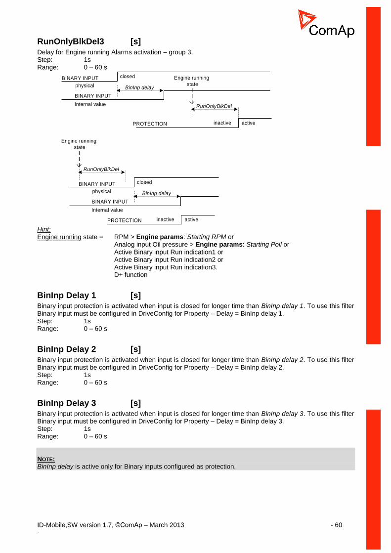
ID-Mobile,SW version 1.7, ©ComAp – March 2013 - 60 -
RunOnlyBlkDel3 [s]
Delay for Engine running Alarms activation – group 3. Step: 1s Range: 0 – 60 s
BINARY INPUT
BinInp delayphysical
BINARY INPUT
closed
Internal value
Engine running
state
RunOnlyBlkDel
PROTECTION activeinactive
BINARY INPUT
BinInp delayphysical
BINARY INPUT
closed
Internal value
Engine running
state
RunOnlyBlkDel
PROTECTION activeinactive
Hint: Engine running state = RPM > Engine params: Starting RPM or Analog input Oil pressure > Engine params: Starting Poil or Active Binary input Run indication1 or Active Binary input Run indication2 or Active Binary input Run indication3. D+ function
BinInp Delay 1 [s] Binary input protection is activated when input is closed for longer time than BinInp delay 1. To use this filter Binary input must be configured in DriveConfig for Property – Delay = BinInp delay 1. Step: 1s Range: 0 – 60 s
BinInp Delay 2 [s] Binary input protection is activated when input is closed for longer time than BinInp delay 2. To use this filter Binary input must be configured in DriveConfig for Property – Delay = BinInp delay 2. Step: 1s Range: 0 – 60 s
BinInp Delay 3 [s] Binary input protection is activated when input is closed for longer time than BinInp delay 3. To use this filter Binary input must be configured in DriveConfig for Property – Delay = BinInp delay 3. Step: 1s Range: 0 – 60 s NOTE: BinInp delay is active only for Binary inputs configured as protection.
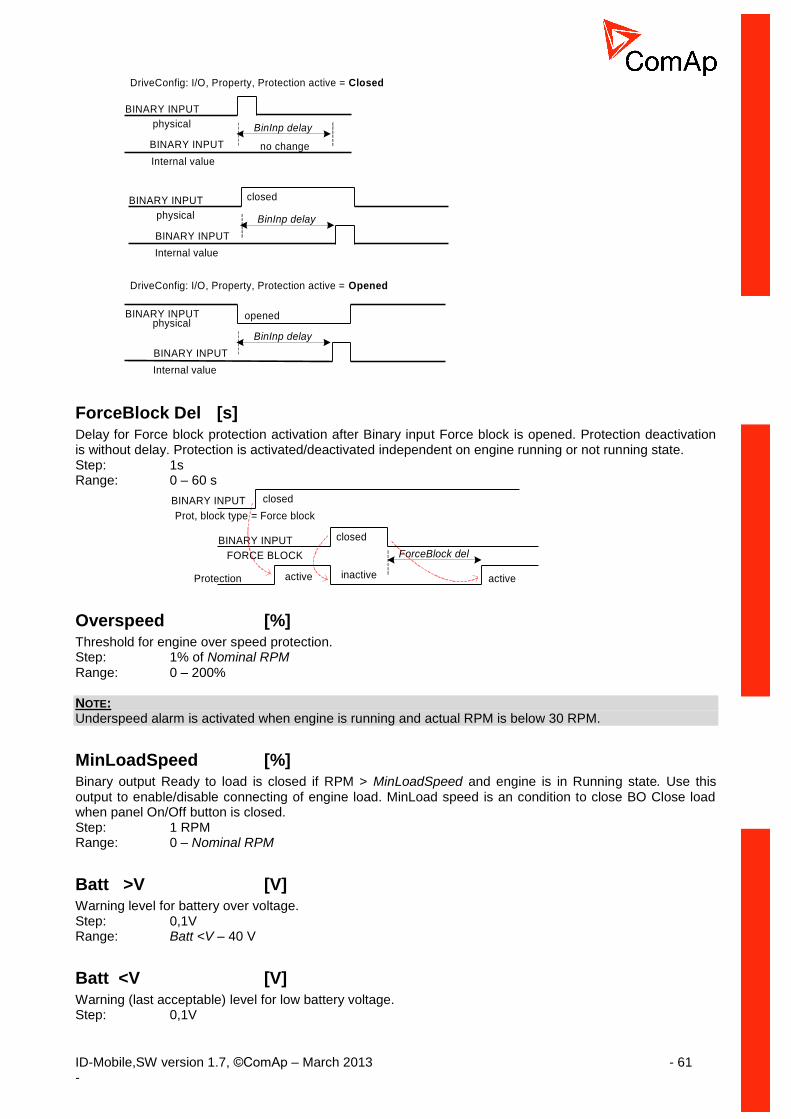
ID-Mobile,SW version 1.7, ©ComAp – March 2013 - 61 -
DriveConfig: I/O, Property, Protection active = Closed
BINARY INPUT
BinInp delayphysical
BINARY INPUT
Internal value
no change
BINARY INPUT
BinInp delayphysical
BINARY INPUT
closed
Internal value
BINARY INPUT
BinInp delay
physical
BINARY INPUT
Internal value
DriveConfig: I/O, Property, Protection active = Opened
opened
ForceBlock Del [s]
Delay for Force block protection activation after Binary input Force block is opened. Protection deactivation is without delay. Protection is activated/deactivated independent on engine running or not running state. Step: 1s Range: 0 – 60 s
BINARY INPUT
ForceBlock delFORCE BLOCK
Protection
closed
BINARY INPUT
Prot, block type = Force block
closed
active activeinactive
Overspeed [%] Threshold for engine over speed protection. Step: 1% of Nominal RPM Range: 0 – 200% NOTE: Underspeed alarm is activated when engine is running and actual RPM is below 30 RPM.
MinLoadSpeed [%] Binary output Ready to load is closed if RPM > MinLoadSpeed and engine is in Running state. Use this output to enable/disable connecting of engine load. MinLoad speed is an condition to close BO Close load when panel On/Off button is closed. Step: 1 RPM Range: 0 – Nominal RPM
Batt >V [V] Warning level for battery over voltage. Step: 0,1V Range: Batt <V – 40 V
Batt <V [V]
Warning (last acceptable) level for low battery voltage. Step: 0,1V

ID-Mobile,SW version 1.7, ©ComAp – March 2013 - 62 -
Range: 8 – Batt >V
Batt Volt Del [s]
Delay for battery voltage alarms. Step: 1s Range: 0 – 600 s
OverloadSpLim [ % ] AS only
Engine overload protection limit.
Overload Del [ s ] AS only Delay for Overload RPM protection limit. Step: 1s Range: 0 – 600 s
Service Time [h] Running hours down counter is decremented when engine is running. Service alarm is indicated in Alarm list and History record activated when counter reach zero. Service time setpoint is actual counter value. Step: 1 h Range: 0 – 65535 h NOTE: Once the service time has elapsed the Service time will have to be adjusted to non-zero value (at least for 30sec) to clear the alarm and begin a new countdown.
Analog Inputs
AIN1 Offset … AIN8 Offset [ - ] Adjustable offset for corresponding analog inputs AIN1 to AIN8. Step: 1 Range: -32767 – 32767
Act. Calls/SMS
Warning Call [DISABLED, ENABLED ]
Enables or disables active calls/SMS to selected phone or mobile numbers when a Warning alarm occurs.
Shut Down Call [DISABLED, ENABLED ] Enables or disables active calls/SMS to selected phone or mobile numbers when a Shut down alarm occurs.
Cool Down Call [DISABLED, ENABLED]
Enables or disables active calls/SMS to selected phone or mobile numbers when a Cool down alarm occurs.
AcallCH1…3-Type [DISABLED, DATA, SMS, E-MAIL, EML-SMS ] 3 channels are available for following types active messages: DISABLED: Channel is disabled

ID-Mobile,SW version 1.7, ©ComAp – March 2013 - 63 -
DATA: Standard analog, GSM or ISDN modem connection to DriveMonitor. SMS: Channel sends SMS message. Only when is GSM modem connected. E-MAIL: Channel sends E-mail. Only when is IG-IB/IB-NT connected. EML-SMS: Channel sends E-mail with short SMS. Only when is IG-IB/IB-NT connected. NOTE: Email contains: - Header with serial number and application info. - Alarm list - 20 History records (reason, date, time)
AcallCH1…3-Addr [Phone number, E-mail address ] 3 channels are available for following types active messages: Address for channel 1...3 active call. Each above message type has either a number or an e-mail address associated to it. For more details see DriveMonitor guide chapter IG-IB Internet communication. NOTE: For GSM numbers use either national format (i.e. like number you will dial if you want to make a local call) or full international format with "+" character followed by international prefix in the beginning NOTE: This setpoint can be modified from PC only!
Num Rings AA [1 – 30]
Number of rings prior to open modem connection from PC to controller NOTE:
NNuummbbeerrRRiinnggss AAAA change is accepted after controller is switched on or when modem is connected to controller.
A.C.Multiplie [1 – 250 ] Setpoint specify the number of attempt to open the Active call connection when the phone line is engaged. NOTE: Timeout for connection is 90 sec and after 120 sec controller starts the next attempt. Incoming calls are blocked during the time the controller is trying to send an active call type.
Modem [TELIT CSD, TELIT GPRS, SIMCOM CSD, SIMCOM GPRS ] Selection of internal modem mode:

ID-Mobile,SW version 1.7, ©ComAp – March 2013 - 64 -
Date and time
Time [HHMMSS]
Controller internal Real Time Clock adjustment.
Date [DDMMYY]
Actual date adjustment.
Time stamp per Time interval for history record. Time base is based on number of minutes since midnight. Step: 1 min Range: 0 - 240 min Hint: No history Time stamp is recorded when TimeStamp Per = 0. RTC and Date is in each History record.
HistoryEntries [ALL TIME, RUNNING ONLY, BI HISTORY ]
The history can be forced to list as follow: ALL TIME: History records are active all time. RUNNING ONLY: History is recorded when engine is running only. BI HISTORY: History record is forced when LBI BBII HHiissttoorryy is configured and liked with binary input.
SummerTimeMod [DISABLED, WINTER, SUMER, WINTER-S, SUMMER-S ] Summer/Winter time applied DISABLED: Automatic switching between summer and wintertime is disabled. WINTER (SUMMER): Automatic switching between summer and wintertime is enabled – set to winter (summer) season. WINTER-S (SUMMER-S): same as above modified for southern hemisphere.
MODULE TYPE OPERATION
MODE DESCRIPTION SUPPORTS
ID-MOBILE GSM
TELIT CSD GSM mode CSD (Circuit Switch Data) Alarm SMS Drive Monitor (via modem connection)
TELIT GPRS Customized interface For special custom application only
ID-MOBILE GPRS
SIMCOM CSD Standard GSM mode CSD (Circuit Switch Data)
Alarm SMS Drive Monitor via modem connection
SIMCIM GPRS GPRS network – enables connection via AirGate
Alarm SMS AirGate Drive Monitor (via AirGate) WebSupervisor

ID-Mobile,SW version 1.7, ©ComAp – March 2013 - 65 -
Position
Home Lat [ 0° 0’ 0.000”N ]
Home Latitude position.
Home Long [ 0° 0’ 0.000”N ] Home Longitude position.
Fence Radius [ m ]
Circle with center in Home position. Step: 1 m Range: 10 m to 10000 m
Fence Delay [ s ] Once the controller is out of FFeennccee RRaaddiiuuss and FFeennccee DDeellaayy time elapsed the engine is shut down. Step: 1 s Range: 0 s to 65535 s NOTE:
WWrrnn GGeeooFFeenncciinngg alarm is announced immediately the controller crosses the FFeennccee RRaaddiiuuss
Geo Fencing [ ENABLED / DISABLED / BIN.INPUT ]
ENABLED: Wrn GeoFencing is enabled. DISABLED: Wrn GeoFencing is disabled. BIN.INPUT: Wrn GeoFencing is enabled when by Binary input GeoFencingEna is closed.
Display
BodasMessage1 … BodasMessage20
Up to 31 characters message can be activated on external (e.g.Bodas) display message screen by corresponding Binary Input BodasMessage-x. Hint: Messages displaying is not available in standard Bodas-1.3 firmware.
PWM Settings
DitFreq [2…30Hz]
frequency of dither (see picture below)
DitAmpl BO9…16 [0,0…10,0%] Amplitude of Dither. (see picture below) CAUTION! If DitAmpl BOx = 0 – Dither function is deactivated NOTE: The frequency of PWM output is fixed fPWM = 1kHz for all PWM available binary outputs (BO9 – BO16)

ID-Mobile,SW version 1.7, ©ComAp – March 2013 - 66 -
NOTE: For more details see Functions/PWM and Dither
Protections
Protection group contains all Analog inputs protection limits and delays. List is dynamically created during configuration process.
PLC
PLC group contains all used PLC setpoints. List is dynamically created during configuration process.

ID-Mobile,SW version 1.7, ©ComAp – March 2013 - 67 -
Event log
Statistic values
It is calculated:
1 Number of starts Each successful start (starter is switched off due to RPM> Starting RPM) is calculated. External (manual) engine start (running indications).
2 Running hours Each finished 60 minutes when engine is running.
3 Number of unsuccessful starts Each finished cranking due to MaxCrank time is over
Level of Statistic values password protection against changing can be configured in DriveConfig.
History records ID-Mobile history length calculation: Each ID-Mobile History record is justified to 32 or 64 or 96 or 128 bytes of length (depends on record structure configuration).
Memory assignment up to: Max.number of events (lines)
1% above separation line (aprox. 23%) 382
below separation line – 50% 190
50% - 79% 126
80% - 100% 95
Separation line
Percentage memory assignment

ID-Mobile,SW version 1.7, ©ComAp – March 2013 - 68 -
Following table contains typical messages. Do not contain messages from ECU.
Events specification Protection type
Information available on binary output
Alarms
GeoFencing WRN *) YES
Wrn Analog input 1 to 8 (16) WRN YES
Sd Analog input 1 to 8 (16) SD YES
ID-MOBILE Binary inputs 1 to 16 Configurable YES
ID-MOBILE Battery voltage <, > WRN YES
Battery flat WRN
Start fail WRN YES
ParamFail NONE
Overspeed SD YES
Underspeed WRN YES
EmergencyStop SD
Pickup fail WRN
Stop fail WRN YES
WrnServiceTime WRN
ChrgAlternFail WRN YES
Fault reset
Local mode ON YES
Local mode OFF
Harbour mode ON YES
Harbour mode OFF
SecBattery YES
Emergency stop
Alarms from IS-AIN8, IS-BIN16/8, ECU
WRN or SD YES
*) and Start blocking
Engine events Note
Starts
CAN control + Button start Start from external terminal
RS485 control + Button start Start from DriveMonitor
Remote start Start from BI
Stops
CAN control + Engine stop Stop from external terminal
RS485 control + Engine stop Stop from DriveMonitor
Remote start ID-MOBILE binary input
RS485 control Start, Stop, Fault reset, On/Off button from DriveMonitor or I-RD
Modem control Start, Stop, Fault reset, On/Off from Modem
SMS control Received command from GSM modem
CAN control Received command via CAN bus e.g. from I-RD or IG-MU
ActCallCH1-OK Successful active call on channel 1
ActCallCH2-OK Successful active call on channel 2
ActCallCH3-OK Successful active call on channel 3
Extern start Manual engine starter handling.
Engine stop Engine changed state from
Emerg.man ON Emergency manual mode ON
Emerg.man OFF Emergency manual mode OFF
Close Load ON Binary output clutch was closed
Close Load OFF Binary output clutch was opened

ID-Mobile,SW version 1.7, ©ComAp – March 2013 - 69 -
Switched on Controller was switched on
Cfg loaded Configuration archive was changed
FwLoaded Firmware upgrade
Time stamp Depends on setpoint setting period
Password set Any level from any terminal
Password changed Any level from any terminal
Access set Access code was set
Access changed Access code was changed
Watchdog Controller internal watchdog protection
Param fail Setpoints checksum fail
RTC battery RTC battery fail
Hint: Value name can’t exceed 11 characters to be recorded to History file with prefix (Wrn, Fls etc..). Longer names characters are canceled.

ID-Mobile,SW version 1.7, ©ComAp – March 2013 - 70 -
Functions
Default archives
The ID-MOBILE controller can be configured for constant or variable speed engines. The configuration can be changed in the DriveConfig software by selecting appropriate archive file. Default configuration is located in …/Archives/Default/ … directory in DriveConfig folder.
Application Archive file Available modes
SS Single speed Mobile-1.0-SS.aid OFF – RUN
AS All speed Mobile-1.0-AS.aid OFF – RUN
Operational modes
OFF mode Engine can’t be started or running engine is stopped, prelubrication function is not active. Firmware and controller configuration can be changed in OFF mode only. OFF mode is available in both applications – SS and AS.
Other functions Controller (except OFF mode) accepts when engine is started outside controller (by hand) or when controller power supply is switched-on on already running engine.
Protections
Protections:
No protection
Warning
Sensor fail
Colldown
Shutdown
Alarm only
HistRecord only
Protections:
No protection
Warning
Sensor fail
Colldown
Shutdown
Alarm only
HistRecord only
Protections:
No protection
Warning
Sensor fail
Colldown
Shutdown
Alarm only
HistRecord only
Sensor
characteristics
+
RI
Analog input
Protections:
No protection
Warning
Sensor fail
Colldown
Shutdown
Alarm only
HistRecord only
Logical analog
input list
Analog output
Binary outputs
State machine
Hardware
jumper

ID-Mobile,SW version 1.7, ©ComAp – March 2013 - 71 -
Logical analog
input list
Analog output
Binary output
State machine
J1939 analog
Protections:
No protection
Warning
Wrn+Colldown
Wrn+Shutdown
Sensor fail
Alarm only
HistRecord only
Protections:
No protection
Warning
Colldown
Shutdown
Sensor fail
Warning+BW
Shutdown+BW
Alarm only
HistRecord only
Logical binary
input list
Binary output
Binary output
State machine
Binary input
(J1939 BI)
Engine start
It is not possible to start engine without RPM signal (from pickup or from J1939) but the Engine stays running when RPM signal is lost (just Wrn Pickup fail is indicated).
Underspeed protection
RPM
active
5 sec
STARTER
Engine params: Starting RPM
PWM and Dither
Dither function is intended to avoid an unpredictable behavior of hydraulic proportional valves caused by hysteresis and stiction. Dither is a rapid, small movement of the spool around desire position which eliminates the stiction and enables more accurate moving of the valve. Typical use – Proportional hydraulic valves Setting of BO PWM and Dither function is available on Binary Output BO9 up to BO16

ID-Mobile,SW version 1.7, ©ComAp – March 2013 - 72 -
Dither function is active only if PWM output type is configured
PROPERTY VALUE DETAILS
OUTPUT TYPE BO Standard Binary Output
PWM Pulse With Modulation (PWM) output
NAME Text Title of the BOUT – maximum 14 charts
SOURCE According to Input Source for output. See list of sources
INVERTED Yes Inversion (negation) of BO signal is active
No Inversion (negation) of BO signal is active
OUTPUT CURVE According to user curves
If no user curve is created the output is linear
LO LIMIT 0% 0% of PWM conforms to physical value (e.g.0%PWM = 0V) See picture below
HI LIMIT 100% 100% of PWM conforms to physical value (e.g.100%PWM = 10V) See picture below

ID-Mobile,SW version 1.7, ©ComAp – March 2013 - 73 -
Example for BO9:
Setpoints Group of Setpoints – PWM Settings
CAUTION! If DitAmpl BOx = 0 – Dither function is deactivated NOTE: The frequency of PWM output is fixed fPWM = 1kHz for all PWM available binary outputs (BO9 – BO16)

ID-Mobile,SW version 1.7, ©ComAp – March 2013 - 74 -
PLC - programmable functions
Following programmable functions are available in ID-MOBILE-Industrial-2.0 software. Use DriveConfig-2.0 or higher software to configure PLC functions. To enable PLC click on PLC modules used in DriveConfig and then go to PLC configuration window.
Available functions
Config item Selection Available
Note
Log Func I. 96
AND, OR 2 to 8 inputs
Log Func II. 32
XOR, RS 2 inputs
Comp Hyst 16
Analog input Two limits Binary output
Comp Time 8
Analog input One limit + delay Binary output
Ana Switch 8
Two analog inputs Analog output Binary input as selector
Math Func 8
ADD, SUB, ABS, AVG, MAX, MIN
Mov Avg 2
Analog input Analog output
InterpolFunc 4
Linear interpolation
ForceHistory 8
Binary input causes history record when changes from 0 to 1
ForceProtect 8
Adjustable protection levels
PID Ana 2
PID control loop with analog output Function was replaced by PID Ana B with adjustable Bias value.

ID-Mobile,SW version 1.7, ©ComAp – March 2013 - 75 -
PID Bin 2
PID control loop with binary output
Counter 4
Edges counter One limit Binary output
Timer 4
Periodic signal generator Binary output Analog input
Delay 24
Adjustable rising and falling edge delay
RAMP 4
Ramp Analog input, analog output. Two setpoints for Ramp-up and down speed (in number of units per second). Enable-Up, Enable-Down: Ena/Disables the ramp.
PID Ana B PID control with Analog output and adjustable Bias 8
PID Analog output jumps to adjustable Bias value when Gate input is active (instead zero as before) and starts from Bias.
Math functions with expandable number of inputs up to 8. 8
Selectable: ADD, AVG, MAX, MIN Eight analog inputs, one analog output.
CMPW Window comparator 16
Comparator Analog input, two limits, analog output. Binary output is active when input is within limits.
Up/Down Request value generator Holding register 6
Analog output is changing within 2 limits (by defined rate of change) when Up/Down binary input is active.
Jump to … 16
Binary input Ena / Disables jump over the selected number of the next following PLC blocks. Jumps to the last one when number of blocks is higher than existing.
Increase / Decrease (Turn switch) 4
Analog output (internal register) can be Increased / Decreased by one with rising edge of binary input “Inc” / “Dec” in range from 0 to adjustable limit (max 65535). Register is Inc / Decreased over zero when "Cycle" option is ticked. Register stops on 0 even other Dec pulses come (or on Max for Inc pulses) when "Cycle" option is not ticked. Example of "Cycle" when Max = 5: 1-2-3-4-5-0-1-... or ...4-3-2-1-0-5-4- ...

ID-Mobile,SW version 1.7, ©ComAp – March 2013 - 76 -
Example of "No-Cycle" when Max = 5: 1-2-3-4-5-5-5-... or ...4-3-2-1-0-0-0- ... Binary input "Reset" switch the Analog output to adjustable “Default” value.
Conversion table 8
Table (conversion) can contain up to 30 items. Input can be connected to (above) Inc/Dec function.
Ana to Bin converter 8
Selected part of Analog input can be decomposed (decoded) to four binary outputs.
Ana formats converter 32
Converts any "Short" and "Long" analog value format to (signed) Integer format compatible with all PLC analog inputs. The invalid Analog output is indicated (####) when Analog input value is out of Integer range.
General specification
Each function output can be configured to - another function in PLC window - from another function input) - any physical terminal (e.g. to controller) - from I/O window
Each function limit (parameter) can be configured as - constant limit (fix): just write requested value into the field (-32000 to +32000) - setpoint limit (customer adjustable): click on field and select one from PLC setpoint list - any value (e.g. from Analog input): click on field and select one from controller or PLC values list
All PLC function analog inputs are signed type and that why the following analog values must not be configured to any comparator and PID analog input:
- Load sharing: ThrottlePos. - Info: ECU DiagSource, Timer val, PasswordDecode. - Statistics: NumSuccStarts, NumUnscStarts, Service time.
All function limits and analog outputs must follow input analog value format: - e.g. input value is 0 to 10,0 bars, then setpoint limit is e.g. 3,2.
Any time and delay limit is in 0,1s step in the range 0,0 to 3276,7 sec.
PLC consistency check indicates incorrect PLC configuration.
PLC values
Binary List contains 128 internal binary values (bits) PLC Bout 1.1 to PLC Bout 1.8 ..... PLC Bout 16.1 to PLC Bout 16.8 that can be configured as any PLC function binary input or output. Anly used PLC Bout x.x can be configured to ID-DCU controller or external modules physical terminals. Used values are visible on controller screen.
Analog It is available 64 internal analog values PLC Aout1 to PLC Aout64 that can be configured as any PLC function input or output.
Any used PLC Aout x can be configured as physical analog output. Used values are visible on controller screen.
PLC resource Unsigned value that is automatically used for Counter, Timer and Inc/Dec functions. Values are visible in DriveMonitor only. Only 8 resources is available for Counter, Timer and Inc/Dec functions.
PLC Setpoints Available 64 setpoints.

ID-Mobile,SW version 1.7, ©ComAp – March 2013 - 77 -
PLC functions description
Log Func I.
Logical functions: AND, OR. Two to eight inputs AND, OR functions are available. Maximal number of functions: 32 OR, AND logic
Input No.1 Input No.2 OR AND
0 0 0 0
0 1 1 0
1 0 1 0
1 1 1 1
I/O Note
Input No. 1 I1 Binary input 1
Input No. 2 I2 Binary input 2
……..
Input No. 8 I8 Binary input 8
Output
Function type “OR” or “AND”
To add/remove input click on + or – button. It is possible to invert any input or output. Maximum number of inputs is 8.
Log Func II.
Logical functions XOR, RS Maximal number of functions: 16. XOR logic
Input No.1 Input No.2 XOR
0 0 0
0 1 1
1 0 1
1 1 0
R-S (Flip-Flop) logic
Input No.1 (S) Input No.2 (R) RS
0 -> 1 0 0 -> 1
1 0 -> 1 1 -> 0
1 -> 0 1 0
0 1 -> 0 0
1 1 -> 0 0 -> 1
I/O Note
Input 1 S input for RS
Input 2 R input for RS
Output Binary output
Function Type “XOR” or “RS”
Comp Hyst
Comparator with hysteresis. Maximal number of functions: 8
I/O Note
Input 1 Analog input
Input On ON limit
Input Off OFF limit
Output Binary output
ON and OFF limit can be configured as - constant limit (fix): just write requested value into the field (-32000 to +32000) - setpoint limit (customer adjustable): click on field and select one from PLC setpoint list - any value (e.g. from Analog input): click on field and select one from controller or PLC values list

ID-Mobile,SW version 1.7, ©ComAp – March 2013 - 78 -
Output signal depends on limits order.
Output
Input ON
Input OFF
Input ON > Input OFF
Input ON < Input OFF
Input ON
Input OFF
Output
Comp Time
Comparator with limit and delay. Maximal number of functions: 8.
I/O Note
Input 1 Analog input
Input 2 ON/OFF limit
Delay Delay [0,1s] in the range: 0,0 to 3276,7 sec.
Output Binary output
ON/OFF limit can be configured as - constant limit (fix): just write requested value into the field (-32000 to +32000) - setpoint limit (customer adjustable): click on field and select one from PLC setpoint list - any value (e.g. from Analog input): click on field and select one from controller or PLC values list
delay delay delay
Input 2
Input 1
Output
Window comparator Comparator indicating the value is within the two limits. Maximal number of functions: 8.
I/O Note
Input 1 Analog input
Input ON ON limit
Input OFF OFF limit
Output Binary output
ON/OFF limits can be configured as - constant limit (fix): just write requested value into the field (-32000 to +32000) - setpoint limit (customer adjustable): click on field and select one from PLC setpoint list - any value (e.g. from Analog input): click on field and select one from controller or PLC values list

ID-Mobile,SW version 1.7, ©ComAp – March 2013 - 79 -
Output Window
Input ON
Input OFF
Input ON > Input OFF
Input ON < Input OFF
Input ON
Input OFF
WindowOutput
Ana Switch Analog switch. Binary input selects which analog input is connected to analog output. Maximal number of functions: 4
I/O Note
Input 1 Analog input 1
Input 2 Analog input 2
Input Sw Input selection. Output = Input1 when Input sw is opened.
Output Analog output
Input 1
Input 2
Output
Switch
Math Func, Extended Math
Mathematical functions from two up to eight analog inputs. Maximal number of functions: 4
I/O Note
Input 1 Analog input 1
Input 2 Analog input 2
…
Input 8
Function type ADD, SUB, ABS, AVG, MAX, MIN
Output Analog output
The same input format is required for both analog inputs (e.g. 0,1).
Function description
ADD Output = A + B
SUB Output = A - B
ABS Output = Absolute (A – B)
AVG Output = (A + B) / 2
MAX Output = MAXIMUM (A; B)
MIN Output = MINIMUM (A; B)

ID-Mobile,SW version 1.7, ©ComAp – March 2013 - 80 -
Input 1
Input 2
Output
ADD
SUB
ABS
AVG
MAX
MIN
Mov Avg Moving average with adjustable weight and period. Maximal number of functions: 2
I/O Note
Input Analog input
Exp.weigh 1 to 5
Period 100 to 5000 ms
Output Analog output
Output value format follows the input format.
InterpolFunc Linear interpolation based on two points line. Analog output corresponds to linear characteristic specified by two points. Max number of functions: 2
I/O Note
X1 The first point X
Y1 The first point Y
X2 The second point X
Y2 The second point Y
Input Analog input
Output Analog output
Analog output format follows analog input.
Output
Input
X1
Y1
X2
Y2
ForceHistory History record is activated when binary input value is changed from 0 to 1. Maximal number of functions: 4

ID-Mobile,SW version 1.7, ©ComAp – March 2013 - 81 -
I/O Note
Input Binary input
ForceProtect Force programmable state. Function activates selected programmable state. Max number of functions: 4
I/O Note
Protection type Select type from the list.
Lvl1 Level 1 protection: Warning
Lvl2 Level 2 protection: Shut down, Cool down
Fls Sensor fail
Connect selected levels to binary input from the list. Selected protection level is activated when corresponding binary input is closed (active).
PID Ana Bias PID control loop with analog output. Maximal number of functions: 2
I/O Note
Input Analog input
Requested value Configure as constant, PLC setpoint or value.
Input GAIN PID proportional factor
Input INT PID integral factor
Input DER PID derivative factor
Input BIAS When binary input GATE is active the BIAS value is forced to output.
Input GATE PID works when gate is not configured. Inactive binary input GATE sets PID output to adjustable Input Bias value and blocks PID calculation when configured.
Output Analog output. Range: -10000 to +10000
Period Period of PID calculation: 100 to 5000 msec.
PID analog input can be configured to any analog value (physical input) Requested value, Input Bias and PID setting can be configured as constant or setpoint or analog value (physical input) from the object list. Sensor fail on measured (or requested) value set PID output to Input bias and blocks PID calculation. There is configurable LoLimit (for 0V or 0mA output) and HiLimit (10VDC or 20mA) for analog output configuration.
PID Bin PID control loop with binary outputs. Maximal number of functions: 2
I/O Note
Input Analog input
Requested value Configure as constant, PLC setpoint or value.
Input GAIN PID proportional factor
Input INT PID integral factor
Input DER PID derivative factor
Input GATE Active binary input GATE blocks PID calculation and set both outputs to zero.
Output Up Binary output UP.
Output Down Binary output DOWN.
Period Period of PID calculation: 100 to 5000 msec.

ID-Mobile,SW version 1.7, ©ComAp – March 2013 - 82 -
Actuator time Period between actuator’s lower and upper stop: 100 to 5000 msec.
PID analog input can be configured to any analog value (physical input) Requested value and PID setting can be configured as constant or setpoint or analog value (physical input) from the object list. Active binary input GATE blocks PID calculation - binary outputs are inactive. Sensor fail on measured (or requested) value blocks PID calculation.
Counter
Impulse counter. Maximal number of functions: 2
I/O Note
Input cnt Counter binary input.
Input clr Counter clear (reset) binary input.
Input lim Analog – limit level input (max 65535).
Output Binary output – over limit indication.
Counter can counts rising or falling edge. The result is stored in volatile memory and it is lost when controller is switched off. Binary output is activated when counter is over limit. Output stays closed even if counter overflow over maximum 65535. Counter contains binary Reset input (level sensitive) that set counter to zero, resets binary output and blocks counting when active. Maximal counter value is 65535 (16 bites wide) and continues to zero. The minimal pulse period is 0,2 sec (max 5 Hz) - in this case the counter overflow after 218 minutes.
Timer
Periodic signal generator. Maximal number of functions: 2
I/O Note
Input reload val Analog value specifies period of Binary output change [ 0,1s].
Input reload Closed binary input Reload reloads timer period when closed.
Input run Binary input must be closed to activate Timer.
Output Binary output.
Binary output changes state with period given by analog Input reload val [ 0,1s ] when Binary input Run is closed and Binary input Reload is opened. Timer starts with low state period when selection Firs down is ticked. E.g. Output changes state each 10 sec when input value is 100. Timer reloads (accepts period change) in the end of period or when binary input Reload is closed. Reload function can be useful when very long time period is running.
Delay
Delay module – adjustable delay for rising/falling edges. Maximal number of functions: 16
I/O Note
Input Binary input.
Input time up Delay of rising edge in 0,1s
Input time down Delay of falling edge in 0,1s
Input reset Binary input to reset output.
Output Binary output.
Rising and Falling edge delay.

ID-Mobile,SW version 1.7, ©ComAp – March 2013 - 83 -
IN
RESET
OUTTup
Tdown
Hint: Use Tdown > Tup for proper functionality
IN
RESET
OUT
Tup
Tdown
IN
RESET
OUTTup
Tdown
Rising and Falling edge delay.
IN
RESET
OUT
Tup
Tdown
IN
RESET
OUTTup Tdown =0
0,1 s
Tdown
Tup
Tinup > 100 ms
IN
RESET
OUT
Noise filter – does not accept input signal shorter than 100 ms.
IN
RESET
OUT
T rstup > 100 ms
Tup
Reset signal function
Puls on edge Function depends on selection Puls on edge. Function generates pulse on rising edge when Input time up is configured or pulse on falling edge when Input time down is configured.

ID-Mobile,SW version 1.7, ©ComAp – March 2013 - 84 -
IN
RESET
OUT Tup Tdown
Two pulses when both Time up and Time down setpoints are configured and input pulse is longer than Time up.
IN
RESET
OUT Tup
Tdown
One common pulse when T up > T in (input)
IN
RESET
OUT
T
Tdown
Tupup
Reset signal function
IN
RESET
Ti
OUTTup
OUTTdown
Tdown =0
OUT
OUT
Tdown =0
< TiTup
Puls on edge
Tup > Ti
Tup > Ti Tdown >0
Single pulse when Tup<Ti and Tdown = 0. Max output pulse length is Ti when Tup>Ti and Tdown = 0. One long pulse “Ti+Tdown” when Tup>Ti and Tdown>0. Two separate pulses when Tup<Ti and Tdown>0.
RAMP
The analog output changes state in constant speed adjustable to different values Up and Down. Maximal number of functions: 4
I/O Note
Input AIN Analog input.
Input time up AIN Ramp-up time in Units per second.
Input time down AIN Ramp-down time in Units per second.
Output AOUT Analog output.
Option: tick EnableUp and EnableDown in PLC RAMP configuration window. The output follows input when both corresponding Enable Up/Dn is not selected and input change is slower than the change given by ‘time-up’ and ‘time-down’ input setpoints.

ID-Mobile,SW version 1.7, ©ComAp – March 2013 - 85 -
Output
Input
Ramp Up Ram
p D
ow
n
Up/Down The analog output is increasing or decreasing according to binary inputs Up and Down activation. Maximal number of functions: 4
I/O Note
Limit1 AIN Up-limit for Analog output.
Limit2 AIN Lo-limit for Analog output.
Reset BIN Binary input to reset the output to Default output value.
Speed up AIN Rising speed (setpoint, constant) - Units per second.
Speed down AIN Falling speed (setpoint, constant) - Units per second.
Up BIN Binary input to activate Analog output increasing.
Down BIN Binary input to activate Analog output decreasing.
Default output value AIN The Analog output switches to this value after start-up or reset or when
both Up and Down inputs are activated.
Analog output AOUT Analog output.
UP/Down block can be used as a Holding register. Required settings for holding register with analog input, binary input and one analog output:
I/O Note
Reset Binary input.
Default output value Analog input.
Output Analog output.
Default output
Input Up
Speed Up
Speed D
own
Limit1
Limit2
Input Down
Reset
Analog output follows analog input if Reset is active if it is not active analog output is frozen and stays at the last known value.
Jump
I/O Note

ID-Mobile,SW version 1.7, ©ComAp – March 2013 - 86 -
Input BIN Jump activation.
Jump over Const. Internal constant – possible to change during configuration only.
Jump to Const. …. Option instead Jump over.
Jump to:
PLC Item 5Binary input
inactive
Jump to:
PLC Item 5Binary input
active
PLC Item 1
PLC Item 2
PLC Item 3
PLC Item 4
PLC Item 5
PLC Item 1
PLC Item 2
PLC Item 3
PLC Item 4
PLC Item 5
Inc/Dec
I/O Note
Inc. BIN Binary input rising edge increase Analog output by one.
Dec. BIN Binary input rising edge decrease Analog output by one.
Reset BIN Binary input rising edge set Analog output to Default (see below).
Max Const. Binary input to activate Analog output increasing.
Default Const. Binary input to activate Analog output decreasing.
Cycle tick Min-Max limit or cycle mode selection.
Analog output AOUT Analog output.
Binary inputs
Increase
Decrease
Reset
Analog outMaximum = ...
Default = ...
Mux const.
I/O Note
Analog input AIN Up-limit for Analog output.
Table Item (primary): fix numbers in the range from 0 to 30.
Analog: up to 30 items of Integer values in the range ±32000. Binary: Decoded Analog values.
Analog output AOUT Analog output.

ID-Mobile,SW version 1.7, ©ComAp – March 2013 - 87 -
Analog input Analog outUp to 30 points
table of integer
Decomposer
I/O Note
Analog input AIN Analog input.
Selected bits selection One of four parts of input value selection.
Test value test Test of bits structure above.
Out 1 BIN Binary output of selected part of input - weight 1.
Out 2 BIN Binary output of selected part of input - weight 2.
Out 3 BIN Binary output of selected part of input - weight 4.
Out 4 BIN Binary output of selected part of input - weight 8.
Analog input
Binary outputs
Out 1
Out 2
Out 3
Out 4
Convert
I/O Note
Analog input AIN Analog input in any “Short” or “Long” format.
Analog output AOUT Analog output = input converted to (signed) Integer16.
Analog input Analog out
Integer
All PLC functions (analog inputs) accepts analog values in integer format (in range from -32768 to +32767) i.e. some values (like Statistics) are not available for PLC. Convert function converts other number formats to integer that can be used by PLC. Convert function accepts input value ≤ +32767 (i.e. in range of integer). The output gives invalid value #### when input value is higher. Conversion examples
Input Output
Dec HEX Dec HEX
Short +0 to +256 00 to FF +0 to +256 0000 to 00FF
Short Int -128 to 127 7F to 80 +127 to -128 007F to 0080
Long 0 to +32767 +32768 and more
0000.0000 to 0000.7FFF 0000.8000 and more
+0 to 32767 #### invalid value
0000 to 7FFF #### invalid value
Long Int -32768 to +32767 lower or higher
0000.8000 to 0000.7FFF
-32768 to +32767 #### invalid value
8000 to 7FFF

ID-Mobile,SW version 1.7, ©ComAp – March 2013 - 88 -
Controller configuration and monitoring
InteliDrive installation package contains separate PC software tools: DriveConfig (DC) and DriveMonitor (DM). DriveConfig and DriveMonitor is based on Windows 95/98/NT/ME/2000/XP/7 or higher platform and requires 15 MByte of hard disc free space.
Direct connection to the PC
ID-Mobile is usually connected with PC via RS485/USB interface or via I-LB (Local Bridge) or via IG-IB (Internet Bridge). No RS232 or USB is available on ID Mobile.
DriveConfig
There are two controller file types:
Firmware Application file (archive) Configuration
ID-Mobile-1.7.idc ID-Mobile-SS-1.7.aim ID-Mobile-AS-1.7.aim
Delivered controller contains firmware and default configuration. This configuration can be modified by customer using DriveConfig PC software (when configuration is not locked). It is possible to download Application file from the controller, modify it and download back. There must be corresponding version of Application file with firmware in controller. Hint: Any ECU Inputs/Outputs configuration procedure has to start from default AS or SS archive. The problems can occur when the finished ECU configuration is simply changed to another ECU (e.g. from Volvo to Scania) without ECU-1 module unselecting (unclicking).
Application (configuration) “aim” file - archive Binary type archive “*.aim” file contains:
Complete I/O configuration (include extension modules if any)
Setpoints setting
All available languages Configuration file can be opened (Open file or Read from controller) modified and stored to the PC (Save, Save as) or downloaded to Controller (Write to controller).
DriveConfig functions
DriveConfig is tool for ID-MOBILE and other InteliDrive controller configuration
Extension modules addressing
All I/O function or protection configuration
Setpoints adjusting
Sensor characteristics modification
History record modification
Password level protection modification (password value must be changed in DriveMonitor)
Controller firmware (mhx file) upgrade
Controller application file Up/Down load
Language translator enables (not available in version 1.0) o Create Dictionary between two languages (Dictionary can be used repeatedly) o Translate current text in Controller (in any language) o Add new language (up to controller memory limit)

ID-Mobile,SW version 1.7, ©ComAp – March 2013 - 89 -
Internal PLC editor
Configuration steps
Hint: Before ID-Mobile ECU configuration switch to ECU list: Option – ESL files … select Mobile.esl Following configuration steps are available in DriveConfig software:
Configure J1939 interface when Electronic engine is connected
Configure Binary inputs as Protection or Function
Configure Binary outputs
Configure Analog inputs as Protection or Function
Define user sensors (in Expert mode only).
Configure History record (in Expert mode only)
Configure password protection
Add/Translate the language (in Expert mode only)
Translator Enables to translate all or some texts to up 5 languages that are all available in controller. Controller language can be changed from panel buttons. It is possible to operate different languages on each ID-MOBILE and Drive Monitor. External display (e.g. Bodas and CANtrak) language depends on specific display firmware. Hint: Check all screens after translation if some texts do not overflow.
DriveMonitor
Functions
On-line direct, Modem or Internet connection
Active Modem or Internet call received from engine to PC (activated by selected Alarm)
Continuous one engine monitoring in on-line connection
On-line or Off-line History record listing
Setpoints listing and adjusting (password protected)
Statistics value (e.g. Running hours) Set/Reset
Password and Access code change
Remote Switches Set/Reset
Connection types
Direct connection via RS485 - up to 1000m.
Modem connection via Analog, ISDN or GSM modem.
Internet connection – Static IP address required. Connection via internet bridge
AirGate connection (no static IP address is required)
Active call (via modem). Controller calls to the preselected telephone number and sends the AID file when active call is activated. To receive AID file the DriveMonitor must be in Active call waiting window.
Off line connection enables open and list Application AID file stored in PC.

ID-Mobile,SW version 1.7, ©ComAp – March 2013 - 90 -
NOTE: More detail regarding different types of connection see in InteliCommunication guide.
Control window: displays all ID-MOBILE and I/O states, enables engine control.
Setpoints: listing and adjusting
Values: reading of all I/O include external modules
History list: complete history list.
Password protection
Password is a four-digit number in 0 – 65535 range. Only setpoints associated with the entered password level can be modified. There are three levels of password protection. 0. User level allows change of non-protected setpoints only 1. Operator level allows change of setpoints protected by Operator level 1. 2. Master level allows change of setpoints protected by Operator 1. and Master level 2. 3. Supervisor highest level allows all setpoints or configuration changes, firmware upgrade. There can be password protected:
Setpoints (depends on configuration)
Statistics values (Level 3 only)
Engine commands (depends on configuration)
Even though one level may have been set from the front panel, the affected setpoints are not accessible from DriveMonitor (direct or Modem) until this level is set in DriveMonitor (direct or Modem). Setpoints opened from front panel are automatically closed 15 minutes after the last key has been depressed or when wrong value of password is set. Password is a four-digit number. Only setpoints associated with the entered password level can be modified. Any password can be changed once that level or supervisor (highest) password has been entered.
Configuration lock
Selection is available in Modules window and can be selected just in On-line mode, because this info is stored in controller memory. Locked configuration file can be loaded from controller but is not visible and cant be modified without password setting.
Modbus protocol
Direct connection: RS485
Modem connection
9600, 19200 or 38400 bps, 57600 (8 data bits, 1 stop bit, no parity)
Transfer mode RTU
Function 3 (Read Multiply Registers)
Function 6 (Write Single Register)

ID-Mobile,SW version 1.7, ©ComAp – March 2013 - 91 -
Function 16 (Write Multiply Registers)
The response to an incoming message is sent with minimum 4.096 ms delay after message reception The complete description of Modbus communication protocol can be found in Modbus Protocol Reference Guide PI-MBUS-300 and Open Modbus Specification Release 1.0. Both documents are available from web site at http://www.modicon.com/openmbus/ .
Modbus Multipack message It is special communication object that contains all values that are used for History record (configurable) and can be read by one command. NOTE: Detail Modbus command description see in ComAp Communication guide.
AirGate and WebSupervisor support
ID-Mobile-controller with ID-Mobile GPRS modem supports the Airgate and WebSupervisor system. This system enables engines fleet management as well as position monitoring (in conjunction with ID-Mobile GPS. For more details on WebSupervisor kindly visit www.comap.cz.
AirGate technology serves for easy plug’n’play communication over Internet. It overcomes problems with fixed and public IP address necessity, with firewalls and difficult communication settings.
GSM/GPRS values in Info group GSM SignalLvl – ID-Mobile-GPRS module show the strength of GSM signal. It is relative value helping to
find the best signal and for troubleshooting cases. Standard external GSM modems usually support it as well.
GSM Diag Code – Troubleshooting diagnostic code for ID-Mobile-GPRS modem.
Code Description
0 OK. No error.
1 Not possible to hang up.
2 ID-Mobile-GPRS is switched off

ID-Mobile,SW version 1.7, ©ComAp – March 2013 - 92 -
3 ID-Mobile-GPRS is switched on
4 ID-Mobile-GPRS – error in initialization
5 ID-Mobile-GPRS – not possible to set the APN
6 ID-Mobile-GPRS – not possible to connect to GPRS network
7 ID-Mobile-GPRS – not possible to retrieve IP address
8 ID-Mobile-GPRS – not accepted DNS IP address
9 Error in modem detection
10 Error in initialization of analog modem
11 SIM card is locked (Possibly PIN code required, PIN needs to be deactivated) or unknown status of SIM locking
12 No GSM signal
13 Not possible to read the SIM card parameters
14 GSM modem did not accepted particular initialization command, possibly caused by locked SIM card
15 Unknown modem
16 Bad answer to complement initialization string
17 Not possible to read GSM signal strength
18 CDMA modem not detected
19 No CDMA network
20 Unsuccessful registration to CDMA network
255 Only running communication is needed to indicate
AirGate Diag – AirGate Troubleshooting diagnostic Code.
Code Description
1 Controller registered, waiting for authorization
2 Not possible to register, controller blacklisted
3 Not possible to register, server has no more capacity
4 Not possible to register, other reason
5 Controller registered and authorized
AirGate ID – Identification name generated by AirGate server for purpose of establishing communication via WebSupervisor DriveMonitor or InteliMonitor. It is communicated on first connection of ID-Mobile controller with ID-Mobile GPRS module. DriveMonitor will need this information when opening connection via AirGate to this controller. WebSupervisor will need this information when user will add this controller.
Modem Status:
"-----" - After controller initialization „Trying“ – modem active, trying to establish connection „Ready“ – modem ready, communication with modem is ok
Short guide how to start using ID-Mobile-GPRS module
Assemble ID-Mobile controller, ID-Mobile-GPRS, antenna, SIM card with GPRS service.
Contact SIM card operator for getting GPRS APN name, username and password.
Make sure SIM card does not require PIN code. If it does, it is possible to disable it in every common mobile telephone.
Power up the ComAp controller and open the DriveMonitor on-line connection.
Enter correct APN Name, APN UserName and APN UserPass in controller’s Comms Settings. Set COM1 Mode = DIRECT.
Switch off the ID-Mobile controller.
Place the SIM card into slot on ID-Mobile-GPRS.
Connect the antenna to designated SMA connector.

ID-Mobile,SW version 1.7, ©ComAp – March 2013 - 93 -
Power up the system.
Wait for approx 2 - 4 minutes for the first connection to the AirGate. Then navigate to DriveMonitor: Info screen where you will find AirGate ID value.
Once this AirGate ID is displayed, connection via AirGate was successful. This value will be needed for LiteEdit or WebSupervisor connection.

ID-Mobile,SW version 1.7, ©ComAp – March 2013 - 94 -
Booting procedure
The ID-Mobile has no protection which is blocking incorrect FW of Mobile platform (ID-Mobile Logger Firmware to ID-Mobile Hardware). After wrong upgrade does the controller not respond (No LEDs are on), the only one way how to upload the correct firmware is with using the Booting procedure CAUTION! Be sure the correct firmware is uploaded to the hardware
You need AT-link converter (ComAp product) – see photo and schematic below.
Connection between AT link converter and PC RS232 or RS232/USB converter

ID-Mobile,SW version 1.7, ©ComAp – March 2013 - 95 -
Connect the AT link converter
uP
AO
UT1
AO
UT2
AO
UT3
AO
UT4
AO
UT5
AO
UT6
AO
UT7
AO
UT8
AIN
1
AIN
2
AIN
3
AIN
4
AIN
5
AIN
6
AIN
7
AIN
8
AIN
9
AIN
10
AIN
11
AIN
12
AIN
13
AIN
14
AIN
15
AIN
16
1 1213 2425 3637 48
49 6061 7273 8485 96
3-2-1 3-2-1 3-2-1 3-2-1 3-2-13-2-1 3-2-1 3-2-1
3-2-1 3-2-1 3-2-1 3-2-1 3-2-13-2-1 3-2-1 3-2-1
-5--4--3--2--1-
-5--4--3--2--1-
-5--4--3--2--1-
-5--4--3--2--1-
-5--4--3--2--1-
-5--4--3--2--1-
-5--4--3--2--1-
-5--4--3--2--1-
-5--4--3--2--1-
-5--4--3--2--1-
-5--4--3--2--1-
-5--4--3--2--1-
-5--4--3--2--1-
-5--4--3--2--1-
-5--4--3--2--1-
-5--4--3--2--1-
BOOT
RES
-3--2--1-
PWMVoutRVout
SGO
20 mA
24 VDC
5 VDC
2,5 kohm
PT 1000
C group - AIN range selection
B group - AOUT mA/Voltage out selection or AOUT / AIN switch
A group - AOUT range selection3-2 = 0-VBatt
2-1 = 0-10V or 0/4-20mA
3-2 = mA 2-1 = Voltage
-1--2--3--4-B
OU
T1 -
BO
UT8
B
W ju
mp
ers
-5--6--7--8-
OFF = disable AOUT / enable AIN
3-2
-1
2-3 Activate to BATT+
1-2 Activate to BATT-
BI1 - BI8 polarity
GSMGPS SCS RS232
POWER
RUN
ALARM
STATUS20 mA
24 VDC
5 VDC
2,5 kohm
PT 1000
12
0R
12
0R
-Bia
s+
Bia
s
RS4
85
12
0R
CA
N1
CA
N2
File/Firmware upgrade and Cloning/FW upgrade (default configuration)…
AT-Link connection port
Boot Jumper

ID-Mobile,SW version 1.7, ©ComAp – March 2013 - 96 -
Select the requested firmware
The upgrade will be processing
Follow instructions on the screen

ID-Mobile,SW version 1.7, ©ComAp – March 2013 - 97 -
Upgrading will continue
Follow instructions
Firmware is upgraded with default archive

ID-Mobile,SW version 1.7, ©ComAp – March 2013 - 98 -
Technical data
Power Supply
Nominal power supply 24 VDC Power supply range 8 – 36 VDC Current consumption 0,34A @ 8V 0.12A @ 24 V 0.09A @ 36 V Battery voltage measurement tolerance 2% at 24V RTC battery life cycle 10 years
Operating conditions
Operating temperature -40 to +80 °C Storage temperature -40 to +80 °C Humidity 97% (accord. IEC 60068-2-30) Flash memory data retention time 10 years Protection (Dust and Water) IP 67 Standard conformity Low Voltage Directive EN 61010-1:95+A1:97 EN 61000-6-2, October 2001 EN 61000-6-4, October 2001 IEC 60533, Ed. 2; 1999-11 Shock test IEC 68-2-27 Vibration resistance IEC 60068-2-6, 5-28Hz/ 1,6mm, 28-150Hz/ 5g EMC compatibility EN61000-6-1/2/3/4, SS4631503(PL4), IEC 255-3
Dimensions
Dimensions 240x200x63mm
Binary inputs
Number of inputs 16 Broken wire detection BI13 – BI16 Input impedance 4,7 kΩ Input Range 0-36VDC Switch voltage level for close contact indication 0-2 V Voltage level for open contact indication 4-36 V Minimal input signal duration 110 ms
Binary outputs
Number of inputs 16 BO1 to BO8 Hi-Side Max continuous current (single channel) 3A
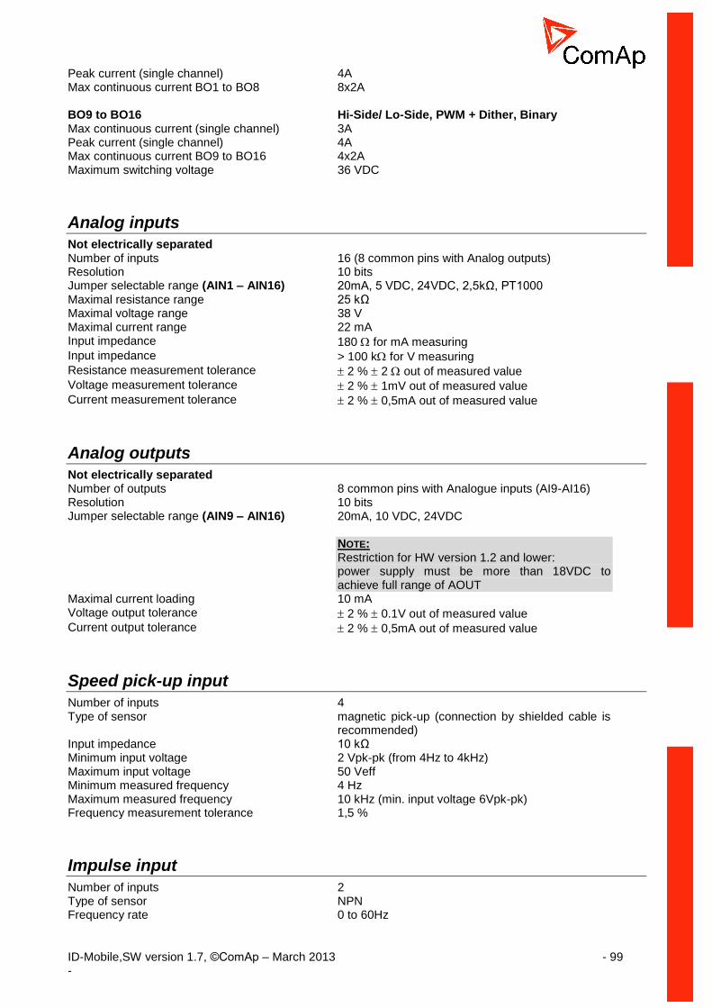
ID-Mobile,SW version 1.7, ©ComAp – March 2013 - 99 -
Peak current (single channel) 4A Max continuous current BO1 to BO8 8x2A BO9 to BO16 Hi-Side/ Lo-Side, PWM + Dither, Binary Max continuous current (single channel) 3A Peak current (single channel) 4A Max continuous current BO9 to BO16 4x2A Maximum switching voltage 36 VDC
Analog inputs
Not electrically separated Number of inputs 16 (8 common pins with Analog outputs) Resolution 10 bits Jumper selectable range (AIN1 – AIN16) 20mA, 5 VDC, 24VDC, 2,5kΩ, PT1000 Maximal resistance range 25 kΩ Maximal voltage range 38 V Maximal current range 22 mA Input impedance 180 for mA measuring Input impedance > 100 k for V measuring Resistance measurement tolerance 2 % 2 out of measured value Voltage measurement tolerance 2 % 1mV out of measured value Current measurement tolerance 2 % 0,5mA out of measured value
Analog outputs
Not electrically separated Number of outputs 8 common pins with Analogue inputs (AI9-AI16) Resolution 10 bits Jumper selectable range (AIN9 – AIN16) 20mA, 10 VDC, 24VDC
NOTE: Restriction for HW version 1.2 and lower: power supply must be more than 18VDC to achieve full range of AOUT
Maximal current loading 10 mA Voltage output tolerance 2 % 0.1V out of measured value Current output tolerance 2 % 0,5mA out of measured value
Speed pick-up input
Number of inputs 4 Type of sensor magnetic pick-up (connection by shielded cable is
recommended) Input impedance 10 kΩ Minimum input voltage 2 Vpk-pk (from 4Hz to 4kHz) Maximum input voltage 50 Veff Minimum measured frequency 4 Hz Maximum measured frequency 10 kHz (min. input voltage 6Vpk-pk) Frequency measurement tolerance 1,5 %
Impulse input
Number of inputs 2 Type of sensor NPN Frequency rate 0 to 60Hz

ID-Mobile,SW version 1.7, ©ComAp – March 2013 - 100 -
Minimum pulse duration 1 ms Input impedance 4 kΩ ON input voltage < 0.8 V OFF input voltage > 4.2V RON max 1 kΩ Maximum input voltage 40V
D+ funcion
Max. D+ output current 300 mA Guaranteed level for signal Charging OK 90% of supply voltage
CAN bus interface
Galvanically separated Maximum CAN bus length
CAN bus mode = 32C 200 m CAN bus mode = 8C 900 m
Speed 32C 250 kBd 8C 64 kBd
Nominal impedance 120 Ω Cable type twisted pair (shielded) min. 75% (max. 4,4 ns/m) Wire crosscut min.0,25 mm
2
Maximal attenuation (at 1 MHz) 2 dB / 100m Recommended Industrial Automation & Process Control Cables: BELDEN (see http://www.belden.com):
3082A DeviceBus for Allen-Bradley DeviceNet
3083A DeviceBus for Allen-Bradley DeviceNet
3086A DeviceBus for Honeywell SDS
3087A DeviceBus for Honeywell SDS
3084A DeviceBus for Allen-Bradley DeviceNet
3085A DeviceBus for Allen-Bradley DeviceNet
3105A Paired EIA Industrial RS485 cable LAPP CABLE (see http://www.lappcable.com)
Unitronic BUS DeviceNet Trunk Cable
Unitronic BUS DeviceNet Drop Cable
Unitronic BUS CAN
Unitronic-FD BUS P CAN UL/CSA
RS 485
Maximal distance 1000m Speed up to 57,6 kBd

ID-Mobile,SW version 1.7, ©ComAp – March 2013 - 101 -
ID-Mobile GPRS
Type Simcom SIM900 Frequency Bands GSM 850; EGSM 900, DCS 1800; PCS 1900;
GSM/GPRS GSM class Small MS Transmitting power Class 4 (2W) at GSM 850 and EGSM 900 Class 1 (1W) at DCS 1800 and PCS 1900 GPRS multi-slot class 10 CSD up to 14.4 kbps TCP/IP communication over GPRS Voltage supply 8-36 VDC
ID-Mobile GSM
Type Telit GC864 Frequency Bands GSM 850; EGSM 900, DCS 1800; PCS 1900;
GSM/GPRS modem Compliant to GSM Phase 2/2+
GSM class Small MS Transmitting power Class 4 (2W) at GSM 850 and EGSM 900 Class 1 (1W) at DCS 1800 and PCS 1900 Sensitivity -107 dBm @ 850 / 900 Mhz
-106 dBm @ 850 / 900 Mhz
ID-Mobile GPS
Type U-BLOX, LEA-5H Receiver type 50 Channels`GPS L1 frequency; C/A Code;
GALILEO Open Service capable, GLONASS Sensitivity Tracking & Navigation – 162 dBm
Reacquisition - 160 dBm Cold Start - 148 dBm
Horizontal position accuracy 2,5 m Accuracy for Timepulse signal RMS 30 ns
99% <60ns Velocity accuracy 0,1 m/s