integration of contact elements in rgib-module of the ...framcos.org/framcos-7/03-23.pdf ·...
TRANSCRIPT
Integration of contact elements in RGIB-module of the finite element software “CESAR-LCPC”: Application to concrete structures affected by internal swelling reactions
O. Omikrine-Metalssi & V.-D. Le Université Paris-Est, Paris, France
J.-F. Seignol Laboratoire Régional des Ponts et Chaussées (LRPC) de Clermont-Ferrand, France
S. Rigobert, P. Humbert & F. Toutlemonde Université Paris-Est, Paris, France
ABSTRACT: A significant number of existing concrete dams are at present deteriorated by chemo-mecha-nical processes known as internal swelling reactions (ISR). These pathologies, which include delayed ettring-ite formation as well as alkali-aggregate reactions, are responsible for cracking and expansion of the material which lead to degradation of structures behaviour. The chemo-mechanical modelling of these phenomena is already elaborated by considering the influence of temperature and humidity in the development of expan-sion. This modelling is valid only for continuous media. In order to widen the domain of modelling applica-bility, this paper describes a novel procedure for modelling displacement discontinuities in ISR-affected con-crete structures, mainly to take into account two phenomena: firstly the modelling of the isolated cracks opening that result from interactions between pathology and mechanical behaviour of the structure, and sec-ondly, the evaluation of the potential efficiency of stress release (e.g. sawing of dams), the procedure of which consists in the creation of cutting lines in the structure for release of excessive compressive stresses, reclosing of the cut being a result of subsequent swelling. The elaborated model, aimed to possibly combine contact elements and non-linear coupled models of durability mechanics related to ISR modelling, was ap-plied to the 3D simulation of ISR in an example of simple gravity dam. Displacements and stresses at the con-tact elements zone were computed and compared with results of the dam computations without contact ele-ments. The results show that the creation of cutting lines in the dam studied leads to decrease of the stresses in the structure, which confirms a favourable effect of this stress release technique in order to deal with ISR affected structures.
1 INTRODUCTION
Internal swelling reactions (ISR) can affect the long-term durability of concrete structures more particu-larly hydraulic concrete structures by causing crack-ing and expansion of the material. These pathologies mainly consist in alkali-aggregate reaction (AAR) and/or delayed ettringite formation (DEF). The Al-kali-Silica Reaction (ASR) is a reaction which oc-curs over time in concrete between the highly alka-line cement paste and reactive non-crystalline silica, which is found in many common aggregates. This reaction causes the expansion of the altered aggre-gate by the formation of a swelling gel of Calcium Silicate Hydrate (CSH). This gel increases in vol-ume with water and exerts an expansive pressure in-side the material, causing loss of strength of the concrete, finally leading to its failure. Meanwhile
delayed ettringite formation (DEF) consists in et-tringite crystallization within concrete after harden-ing is substantially complete, and in which no sul-phates come from outside the cement paste. It may occur in materials that have been subjected to tem-perature above about 65°C and to high humidity.
The occurrence of these two phenomena in several concrete structures in the last years worldwide has pointed out the need for improvement of preventive measures to inhibit these reactions in affected struc-tures. Moreover, prediction of concrete expansion and degradation and assessment of efficiency and periodicity of rehabilitation operations are crucial points for existing affected structures.
Several types of models to simulate the behaviour of structures affected by (ISR) have been presented in the literature (Léger et al. 1996, Ulm 1999 for ASR and Zhang et al. 2002, Brunetaud 2006, Heinz
Fracture Mechanics of Concrete and Concrete Structures -Recent Advances in Fracture Mechanics of Concrete - B. H. Oh, et al.(eds)
ⓒ 2010 Korea Concrete Institute, Seoul, ISBN 978-89-5708-180-8
& Ludwig 1987, Garboczi 1997 for DEF). However, in this study, we improved models proposed by Li et
al. (2004) for ASR and Baghdadi et al. (2007), Baghdadi (2008) for DEF.
The modelling of these phenomena in CESAR-LCPC Finite Element code was based on a sub pro-gram called “ALKA”, for ASR, and newly developed sub program called “RGIB” that allows modeling the behaviour of a structure affected by ASR or DEF. This program takes into account several cou-pled phenomena: effects of the early age thermal history, anisotropy of the imposed expansion related to the direction of concrete casting, damage resulting from cracking of the material, drying shrinkage and coupling between the expansion and the state of stresses.
Many case-studies have shown that it is necessary to model displacement discontinuities in the concrete, mainly to take into account two phenomena:
• In addition to multi-cracking, observation of isolated cracks with an important opening, resulting from interactions between pathology and mechanical stresses applied to the structure. Control of these cracks opening sometimes requires an explicit modelling.
• Among techniques available to deal with ISR affected structures, the stress release can be effective (e.g. sawing of dams). To evaluate the potential effi-ciency of this technique, creation of cutting lines in the structure, and reclosing of the cut as a result of subsequent swelling, need to be modelled.
In this paper, we describe the algorithm develop-ment aimed to possibly combine contact elements, which the modelling was elaborated by Richer (1985), and non-linear coupled models of durability mechanics related to ISR modelling, and we present validation and illustrative cases of simple gravity dam.
2 PRESENTATION OF SOFTWARE BACKGROUND AND DEVELOPMENTS
CESAR-LCPC is a finite element software, devel-oped at the LCPC since 1981 (Humbert et al. 2005). It is a finite element general software particularly adapted to the resolution of Civil Engineering prob-lems (structural analysis, soil mechanics, etc). It in-cludes modules of data management, libraries of elements and computational modules. In this study, contact elements were integrated in the sub-program called “RGIB” aimed to the recalculation of struc-tures affected by internal swelling reaction, by using an other sub-program called “TCNL” which is dedi-cated to solving contact calculation between two non-linear solids. The finally improved RGIB-module will especially allow modeling the “sawing treatment” of ISR-affected dams.
2.1 RGIB module
Within the framework of the methodology elabo-rated for the expertise of ISR-affected concrete structures (LPC 2003), a method of structures recal-culation has been developed. This method consists, from the information collected on the damaged structures and from the possible additional tests on reconstituted concrete, in calibrating the parameters of the laws that constitute the model. An algorithm of resolution was designed for the recalculation of structures affected by DEF or by ASR (Baghdadi 2008). It is implemented in CESAR-LCPC as “RGIB” module (Internal Swelling Reaction in Con-crete) and consists in an evolution of the existing module “ALKA” which concerns the recalculation of concrete structures affected by ASR (Li et al. 2004, Seignol, Dubouchet 2006).
To model the kinetics of swelling reaction in rela-tion with its mechanical consequences the curves of deformation versus time from the free expansion tests realized in laboratory under very specific envi-ronmental conditions have been used. These expan-sion curves have the shape of a sigmoid which can be described mathematically by using the following Equation (Brunetaud 2006, Baghdadi 2008):
⎟⎠
⎞⎜⎝
⎛
++
+
−=
⎟⎟⎟
⎠
⎞
⎜⎜⎜
⎝
⎛+−
⎟⎟⎠
⎞⎜⎜⎝
⎛−
∞t
e
et
c
L
c
t
c
t
δ
ϕεε
τ
τ
τ
τ
χ1
1
1)(
0
0
0
0
0 (1)
where:
0
∞ε : Potential of expansion, 0
cτ : Characteristic time,
0
Lτ : Latency time, ϕ and δ : coefficients characterizing the last pseudo-asymptotic phase of expansion.
Many results show that several factors influence
the amplitude and the kinetics of the swelling in-duced by DEF and ASR (Brunetaud 2006, Petrov 2003). Coupling laws have to describe the relation between the parameters of the expansion law pre-sented in the equation (1) and the environmental conditions to which the structure is subjected, whether during its construction or during its lifetime.
The experiments made by (Lawrence 1995, Pet-rov 2003, Fu et al. 1994) showed that a higher cur-ing temperature leads to increase the amplitude of final expansion. The duration of exposure to high temperature also amplifies the phenomenon (Bru-netaud 2006).
Some works on the effect of the humidity on the ISR have been made. Those of Heinz & Ludwing (1987) showed that no expansion is observed below 90% of relative humidity even after 780 days. The final expansions are higher and latency/characteristic
Proceedings of FraMCoS-7, May 23-28, 2010
hThD ∇−= ),(J (1)
The proportionality coefficient D(h,T) is called moisture permeability and it is a nonlinear function of the relative humidity h and temperature T (Bažant & Najjar 1972). The moisture mass balance requires that the variation in time of the water mass per unit volume of concrete (water content w) be equal to the divergence of the moisture flux J
J•∇=∂
∂−
t
w (2)
The water content w can be expressed as the sum
of the evaporable water we (capillary water, water vapor, and adsorbed water) and the non-evaporable (chemically bound) water wn (Mills 1966, Pantazopoulo & Mills 1995). It is reasonable to assume that the evaporable water is a function of relative humidity, h, degree of hydration, αc, and degree of silica fume reaction, αs, i.e. we=we(h,αc,αs) = age-dependent sorption/desorption isotherm (Norling Mjonell 1997). Under this assumption and by substituting Equation 1 into Equation 2 one obtains
nscw
s
ew
c
ew
hh
Dt
h
h
ew
&&& ++∂
∂
∂
∂
=∇•∇+∂
∂
∂
∂
− αα
αα
)(
(3)
where ∂we/∂h is the slope of the sorption/desorption isotherm (also called moisture capacity). The governing equation (Equation 3) must be completed by appropriate boundary and initial conditions.
The relation between the amount of evaporable water and relative humidity is called ‘‘adsorption isotherm” if measured with increasing relativity humidity and ‘‘desorption isotherm” in the opposite case. Neglecting their difference (Xi et al. 1994), in the following, ‘‘sorption isotherm” will be used with reference to both sorption and desorption conditions. By the way, if the hysteresis of the moisture isotherm would be taken into account, two different relation, evaporable water vs relative humidity, must be used according to the sign of the variation of the relativity humidity. The shape of the sorption isotherm for HPC is influenced by many parameters, especially those that influence extent and rate of the chemical reactions and, in turn, determine pore structure and pore size distribution (water-to-cement ratio, cement chemical composition, SF content, curing time and method, temperature, mix additives, etc.). In the literature various formulations can be found to describe the sorption isotherm of normal concrete (Xi et al. 1994). However, in the present paper the semi-empirical expression proposed by Norling Mjornell (1997) is adopted because it
explicitly accounts for the evolution of hydration reaction and SF content. This sorption isotherm reads
( ) ( )( )
( ) ( )⎥⎥
⎦
⎤
⎢⎢
⎣
⎡
⎥⎥⎥
⎦
⎤
⎢⎢⎢
⎣
⎡
−
−∞
+
−∞
−=
1110
,1
110
11,
1,,
hcc
ge
scK
hcc
ge
scG
sch
ew
αα
αα
αα
αααα
(4)
where the first term (gel isotherm) represents the physically bound (adsorbed) water and the second term (capillary isotherm) represents the capillary water. This expression is valid only for low content of SF. The coefficient G1 represents the amount of water per unit volume held in the gel pores at 100% relative humidity, and it can be expressed (Norling Mjornell 1997) as
( ) ss
s
vgkc
c
c
vgk
scG αααα +=,1
(5)
where k
cvg and k
svg are material parameters. From the
maximum amount of water per unit volume that can fill all pores (both capillary pores and gel pores), one can calculate K1 as one obtains
( )1
110
110
11
22.0188.00
,1
−⎟⎠
⎞⎜⎝
⎛−∞
⎥⎥⎥
⎦
⎤
⎢⎢⎢
⎣
⎡⎟⎠
⎞⎜⎝
⎛−∞
−−+−
=
hcc
ge
hcc
geGs
ssc
w
scK
αα
αα
αα
αα
(6)
The material parameters k
cvg and k
svg and g1 can
be calibrated by fitting experimental data relevant to free (evaporable) water content in concrete at various ages (Di Luzio & Cusatis 2009b).
2.2 Temperature evolution
Note that, at early age, since the chemical reactions associated with cement hydration and SF reaction are exothermic, the temperature field is not uniform for non-adiabatic systems even if the environmental temperature is constant. Heat conduction can be described in concrete, at least for temperature not exceeding 100°C (Bažant & Kaplan 1996), by Fourier’s law, which reads
T∇−= λq (7)
where q is the heat flux, T is the absolute temperature, and λ is the heat conductivity; in this

times are shorter when the samples are kept in the water rather than 100 % of relative humidity.
To describe the influence of the moisture content on the kinetics and the amplitude, the laws presented by Poyet (2003) have been implemented after. A sensitivity analysis is detailed in Seignol et al. (2006).
The adopted approach in the modelling of the chemo-mechanical coupling is based on the assump-tion of prescribed chemical strains superimposed to mechanical deformations (Li et al. 2004, Baghdadi et al. 2008).
2.2 TCNL module
The module “TCNL” is based on the method of pe-nalization which was developed in CESAR for con-
tact description especially using contact elements. This method introduces a specific and variable rigid-ity matrix at the level of the interface because it de-pends on the state (open/closed) of this interface at each iteration step (Richer 1985). In practice, this matrix is taken into account by adding, in the mesh of the structure, the special contact elements along the surface of contact. The principle of resolution requires to update the rigidity matrix at each itera-tion step, depending on the evolution of the contact interface, but avoids its reconditioning. Normally in a linear system where degrees of freedom are cre-ated or suppressed, the rigidity matrix must be re-conditioned. With this method, the number of de-grees of freedom remains constant on the surface due to the presence of the matrix of penalization.
The advantage of this method is that the contact
Figure 1. Resolution algorithm for RGIB-TCNL coupling problem.
Proceedings of FraMCoS-7, May 23-28, 2010
hThD ∇−= ),(J (1)
The proportionality coefficient D(h,T) is called moisture permeability and it is a nonlinear function of the relative humidity h and temperature T (Bažant & Najjar 1972). The moisture mass balance requires that the variation in time of the water mass per unit volume of concrete (water content w) be equal to the divergence of the moisture flux J
J•∇=∂
∂−
t
w (2)
The water content w can be expressed as the sum
of the evaporable water we (capillary water, water vapor, and adsorbed water) and the non-evaporable (chemically bound) water wn (Mills 1966, Pantazopoulo & Mills 1995). It is reasonable to assume that the evaporable water is a function of relative humidity, h, degree of hydration, αc, and degree of silica fume reaction, αs, i.e. we=we(h,αc,αs) = age-dependent sorption/desorption isotherm (Norling Mjonell 1997). Under this assumption and by substituting Equation 1 into Equation 2 one obtains
nscw
s
ew
c
ew
hh
Dt
h
h
ew
&&& ++∂
∂
∂
∂
=∇•∇+∂
∂
∂
∂
− αα
αα
)(
(3)
where ∂we/∂h is the slope of the sorption/desorption isotherm (also called moisture capacity). The governing equation (Equation 3) must be completed by appropriate boundary and initial conditions.
The relation between the amount of evaporable water and relative humidity is called ‘‘adsorption isotherm” if measured with increasing relativity humidity and ‘‘desorption isotherm” in the opposite case. Neglecting their difference (Xi et al. 1994), in the following, ‘‘sorption isotherm” will be used with reference to both sorption and desorption conditions. By the way, if the hysteresis of the moisture isotherm would be taken into account, two different relation, evaporable water vs relative humidity, must be used according to the sign of the variation of the relativity humidity. The shape of the sorption isotherm for HPC is influenced by many parameters, especially those that influence extent and rate of the chemical reactions and, in turn, determine pore structure and pore size distribution (water-to-cement ratio, cement chemical composition, SF content, curing time and method, temperature, mix additives, etc.). In the literature various formulations can be found to describe the sorption isotherm of normal concrete (Xi et al. 1994). However, in the present paper the semi-empirical expression proposed by Norling Mjornell (1997) is adopted because it
explicitly accounts for the evolution of hydration reaction and SF content. This sorption isotherm reads
( ) ( )( )
( ) ( )⎥⎥
⎦
⎤
⎢⎢
⎣
⎡
⎥⎥⎥
⎦
⎤
⎢⎢⎢
⎣
⎡
−
−∞
+
−∞
−=
1110
,1
110
11,
1,,
hcc
ge
scK
hcc
ge
scG
sch
ew
αα
αα
αα
αααα
(4)
where the first term (gel isotherm) represents the physically bound (adsorbed) water and the second term (capillary isotherm) represents the capillary water. This expression is valid only for low content of SF. The coefficient G1 represents the amount of water per unit volume held in the gel pores at 100% relative humidity, and it can be expressed (Norling Mjornell 1997) as
( ) ss
s
vgkc
c
c
vgk
scG αααα +=,1
(5)
where k
cvg and k
svg are material parameters. From the
maximum amount of water per unit volume that can fill all pores (both capillary pores and gel pores), one can calculate K1 as one obtains
( )1
110
110
11
22.0188.00
,1
−⎟⎠
⎞⎜⎝
⎛−∞
⎥⎥⎥
⎦
⎤
⎢⎢⎢
⎣
⎡⎟⎠
⎞⎜⎝
⎛−∞
−−+−
=
hcc
ge
hcc
geGs
ssc
w
scK
αα
αα
αα
αα
(6)
The material parameters k
cvg and k
svg and g1 can
be calibrated by fitting experimental data relevant to free (evaporable) water content in concrete at various ages (Di Luzio & Cusatis 2009b).
2.2 Temperature evolution
Note that, at early age, since the chemical reactions associated with cement hydration and SF reaction are exothermic, the temperature field is not uniform for non-adiabatic systems even if the environmental temperature is constant. Heat conduction can be described in concrete, at least for temperature not exceeding 100°C (Bažant & Kaplan 1996), by Fourier’s law, which reads
T∇−= λq (7)
where q is the heat flux, T is the absolute temperature, and λ is the heat conductivity; in this

elements on the potential contact surface are taken into account in the same way as the general elements of the structure, that is, through their matrix of rigid-ity, which is assembled in the global matrix of rigid-ity of the structure. These contact elements have to ensure the continuity of normal and tangential dis-placements in the interface. For the model used here the elements have a weak thickness but not null; the interface is then represented by a fictitious contact material and the interface elements have mechanical properties identical to the rest of the structure. The number of nodes must be compatible with that of the elements which constitute the media on both sides of the interface.
The principle of resolution consists in proceeding to a progressive loading in order to follow the evolu-tion of the effective surface of contact. For each of these loads, we verify by an iterative process the equilibrium Equations and the criteria of contact. The changing of the effective surface of contact re-sults in the modification of the matrix of rigidity of the contact element and thus the global matrix of ri-gidity. For each iteration step, we proceed to three tests: a test of non-interpenetration, a test on the normal stress and a test of friction. The first verifica-tion consists in ensuring that there is no interpen-etration at the level of the inactive contact elements of the potential surface of contact. The second test consists in verifying that the normal stress in a point of the effective surface of contact is lower or equal to the tensile strength (detachment test). The last test consists in verifying that Coulomb’s friction law (generally used) is satisfied at every point of the ac-tive structure area.
2.3 Coupling algorithm
The coupling algorithm of RGIB and contact ele-ments is shown in Figure 1. Firstly, From the fields of temperature and humidity, and chemical parame-ters of the material, RGIB-module calculates the ad-vancement degree of the reaction for each time step (in the case of internal sulfate attack, we have to make the early age thermal calculation first in order to have swelling potential in the structure). Then, this advancement degree is introduced into the chemo-mechanical model which leads to calculates, from a plastic or elastic law, the effects of ISR (strains, displacements, stresses). For coupling RGIB with contact elements, it is mandatory to in-clude in the mesh the location of contact elements. These are non-active for preliminary thermal and hydric calculations and become active in the mesh during mechanical calculations. The integration of these contact elements in the calculations is made by an assemblage of their rigidity matrix and by calcu-lating the stresses and strains at time t and t+∆t, by checking for each iteration step, the constitutive
laws that govern contact criteria (interpenetration, friction, detachment). When the calculations con-verge, this coupling RGIB- contact element allows to have the evolution of strains and stresses through-out the studied structure including at the contact elements zone.
3 APPLICATION TO A SIMPLE DAM STRUCTURE
3.1 Materials, mesh characteristics and parameters
An idealized part of an ASR-affected gravity dam has been used for illustrating the capacities of the developed module. The numerical simulations have been carried out, assuming concrete Young’s modulus and Poisson’s ratio equal to Ec = 30000 MPa and υ = 0.20 respectively. Mass density of concrete is taken as ρ = 2400 kg/m
3. The duration of the analysis is 50
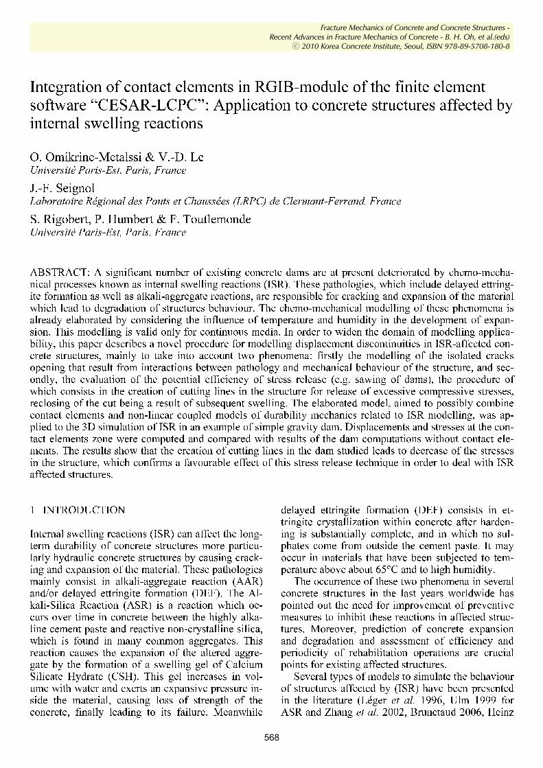
years, assuming one year-long time steps. Total of 650 three dimensional elements and 3392 nodes in the entire model are used for finite elements calcula-tions. The main geometric characteristics and the fi-nite element mesh used for the simulations are shown in Figure 2. The values of the thermal and humidity fields are considered as constant. The am-bient temperature and the relative humidity taken into account are of 15 °C and 100 % respectively. Temperature and humidity fields were computed us-ing the “DTNL” module in CESAR-LCPC as shown in Figure 1 and these results are used to calculate the chemical strain in the RGIB module (Baghdadi 2008).
For the determination of the reaction kinetics (Eq. 1) we used the following values: τc = 6 years; τL = 6 years; ε∞ = 0.0015, φ = δ = 0. These parameters are attached to a reference temperature of 15 ° C.
As for the boundary conditions, the transverse displacements were restrained on both sides, while the foundation of the dam was considered as damped (Fig. 3). The notch in the dam is represented by a contact elements zone (P1 to P6). Various constitu-tive laws can be envisaged for these types of ele-ments: perfect sliding, adhesion, Coulomb friction. Each of these laws is associated to a constitutive ma-trix that allows to ensure the continuity on the corre-sponding displacements. For perfect sliding, the con-tact elements must only ensure the continuity of normal displacement, while for adhesion, these ele-ments must also ensure the equality of tangential displacements. For friction, the relation between normal and shear stresses is controlled by Coulomb's law.
In the case of the studied structure, the sawing operation is assumed to have been performed after 10 years (sawing thickness is 1 cm). The mechanical behaviour of the structure can thus be compared with the reference state (without sawing). Further-
Proceedings of FraMCoS-7, May 23-28, 2010
hThD ∇−= ),(J (1)
The proportionality coefficient D(h,T) is called moisture permeability and it is a nonlinear function of the relative humidity h and temperature T (Bažant & Najjar 1972). The moisture mass balance requires that the variation in time of the water mass per unit volume of concrete (water content w) be equal to the divergence of the moisture flux J
J•∇=∂
∂−
t
w (2)
The water content w can be expressed as the sum
of the evaporable water we (capillary water, water vapor, and adsorbed water) and the non-evaporable (chemically bound) water wn (Mills 1966, Pantazopoulo & Mills 1995). It is reasonable to assume that the evaporable water is a function of relative humidity, h, degree of hydration, αc, and degree of silica fume reaction, αs, i.e. we=we(h,αc,αs) = age-dependent sorption/desorption isotherm (Norling Mjonell 1997). Under this assumption and by substituting Equation 1 into Equation 2 one obtains
nscw
s
ew
c
ew
hh
Dt
h
h
ew
&&& ++∂
∂
∂
∂
=∇•∇+∂
∂
∂
∂
− αα
αα
)(
(3)
where ∂we/∂h is the slope of the sorption/desorption isotherm (also called moisture capacity). The governing equation (Equation 3) must be completed by appropriate boundary and initial conditions.
The relation between the amount of evaporable water and relative humidity is called ‘‘adsorption isotherm” if measured with increasing relativity humidity and ‘‘desorption isotherm” in the opposite case. Neglecting their difference (Xi et al. 1994), in the following, ‘‘sorption isotherm” will be used with reference to both sorption and desorption conditions. By the way, if the hysteresis of the moisture isotherm would be taken into account, two different relation, evaporable water vs relative humidity, must be used according to the sign of the variation of the relativity humidity. The shape of the sorption isotherm for HPC is influenced by many parameters, especially those that influence extent and rate of the chemical reactions and, in turn, determine pore structure and pore size distribution (water-to-cement ratio, cement chemical composition, SF content, curing time and method, temperature, mix additives, etc.). In the literature various formulations can be found to describe the sorption isotherm of normal concrete (Xi et al. 1994). However, in the present paper the semi-empirical expression proposed by Norling Mjornell (1997) is adopted because it
explicitly accounts for the evolution of hydration reaction and SF content. This sorption isotherm reads
( ) ( )( )
( ) ( )⎥⎥
⎦
⎤
⎢⎢
⎣
⎡
⎥⎥⎥
⎦
⎤
⎢⎢⎢
⎣
⎡
−
−∞
+
−∞
−=
1110
,1
110
11,
1,,
hcc
ge
scK
hcc
ge
scG
sch
ew
αα
αα
αα
αααα
(4)
where the first term (gel isotherm) represents the physically bound (adsorbed) water and the second term (capillary isotherm) represents the capillary water. This expression is valid only for low content of SF. The coefficient G1 represents the amount of water per unit volume held in the gel pores at 100% relative humidity, and it can be expressed (Norling Mjornell 1997) as
( ) ss
s
vgkc
c
c
vgk
scG αααα +=,1
(5)
where k
cvg and k
svg are material parameters. From the
maximum amount of water per unit volume that can fill all pores (both capillary pores and gel pores), one can calculate K1 as one obtains
( )1
110
110
11
22.0188.00
,1
−⎟⎠
⎞⎜⎝
⎛−∞
⎥⎥⎥
⎦
⎤
⎢⎢⎢
⎣
⎡⎟⎠
⎞⎜⎝
⎛−∞
−−+−
=
hcc
ge
hcc
geGs
ssc
w
scK
αα
αα
αα
αα
(6)
The material parameters k
cvg and k
svg and g1 can
be calibrated by fitting experimental data relevant to free (evaporable) water content in concrete at various ages (Di Luzio & Cusatis 2009b).
2.2 Temperature evolution
Note that, at early age, since the chemical reactions associated with cement hydration and SF reaction are exothermic, the temperature field is not uniform for non-adiabatic systems even if the environmental temperature is constant. Heat conduction can be described in concrete, at least for temperature not exceeding 100°C (Bažant & Kaplan 1996), by Fourier’s law, which reads
T∇−= λq (7)
where q is the heat flux, T is the absolute temperature, and λ is the heat conductivity; in this
more, the reclosing of the two sides of the notch fol-lowing the swelling of the dam was simulated. The results were compared with reference states either without sawing, or with a notch created from the construction time.
Figure 2. Geometric characteristics of the dam and finite ele-ment mesh.
Figure 3. Contact elements and boundary conditions in the dam studied.
3.2 Results
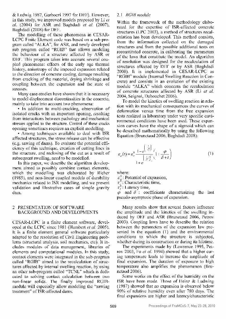
3.2.1 Sawing after construction Figure 4 shows the variation of vertical displace-ment versus time of points (P1 to P6) for the dam studied, with and without sawing on the graphs, “CE” stands for “contact elements”. This displace-ment increases with time and become more impor-tant when one approaches the upper surface for both cases. It stabilize after about 25 years. By comparing the results, this vertical displacement stays more im-portant in the case without sawing (by about 5 %).
Figure 4. Vertical displacement vs. time along the sawing line (with and without sawing).
The variation of transverse displacements versus
time is presented in Figure 5. The notch closes pro-gressively from point P1 to P5 in less than 10 years. Only point (P6) is open as its transverse displace-ment stays lower than the value of sawing thickness. The results for the strain at this point (P6) have no physical meaning since this one is considered as a connection point between the end of the notch and the solid block which represents the base of the dam.
Figure 5. Transverse displacement vs. time along the sawing line after sawing.
For the variation of transverse stresses versus
time, Figure 6 shows the curves for both cases: with and without sawing. For the reference case, the transverse stress increases with time until its stabili-zation at a value of 45 MPa. This value is roughly consistent with 0
.
cE
∞ε . While in the case of sawing, the
transverse stress stays equal to zero until the pro-gressive reclosing of the notch. Then it increases and stabilizes at values of 30 to 35 MPa. These stress values are in agreement with the theoretical values calculated at the end of the swelling. Indeed, with the sawing line thickness e = 1 cm made on the part of dam whose width is L = 20 m, the maximum transverse stress is given by (Eq. 2):
L
eEE
c..
0−=
∞εσ (2)
The tensile value of transverse stress at point (P6)
highlights that the notch at this point stays open. As
Proceedings of FraMCoS-7, May 23-28, 2010
hThD ∇−= ),(J (1)
The proportionality coefficient D(h,T) is called moisture permeability and it is a nonlinear function of the relative humidity h and temperature T (Bažant & Najjar 1972). The moisture mass balance requires that the variation in time of the water mass per unit volume of concrete (water content w) be equal to the divergence of the moisture flux J
J•∇=∂
∂−
t
w (2)
The water content w can be expressed as the sum
of the evaporable water we (capillary water, water vapor, and adsorbed water) and the non-evaporable (chemically bound) water wn (Mills 1966, Pantazopoulo & Mills 1995). It is reasonable to assume that the evaporable water is a function of relative humidity, h, degree of hydration, αc, and degree of silica fume reaction, αs, i.e. we=we(h,αc,αs) = age-dependent sorption/desorption isotherm (Norling Mjonell 1997). Under this assumption and by substituting Equation 1 into Equation 2 one obtains
nscw
s
ew
c
ew
hh
Dt
h
h
ew
&&& ++∂
∂
∂
∂
=∇•∇+∂
∂
∂
∂
− αα
αα
)(
(3)
where ∂we/∂h is the slope of the sorption/desorption isotherm (also called moisture capacity). The governing equation (Equation 3) must be completed by appropriate boundary and initial conditions.
The relation between the amount of evaporable water and relative humidity is called ‘‘adsorption isotherm” if measured with increasing relativity humidity and ‘‘desorption isotherm” in the opposite case. Neglecting their difference (Xi et al. 1994), in the following, ‘‘sorption isotherm” will be used with reference to both sorption and desorption conditions. By the way, if the hysteresis of the moisture isotherm would be taken into account, two different relation, evaporable water vs relative humidity, must be used according to the sign of the variation of the relativity humidity. The shape of the sorption isotherm for HPC is influenced by many parameters, especially those that influence extent and rate of the chemical reactions and, in turn, determine pore structure and pore size distribution (water-to-cement ratio, cement chemical composition, SF content, curing time and method, temperature, mix additives, etc.). In the literature various formulations can be found to describe the sorption isotherm of normal concrete (Xi et al. 1994). However, in the present paper the semi-empirical expression proposed by Norling Mjornell (1997) is adopted because it
explicitly accounts for the evolution of hydration reaction and SF content. This sorption isotherm reads
( ) ( )( )
( ) ( )⎥⎥
⎦
⎤
⎢⎢
⎣
⎡
⎥⎥⎥
⎦
⎤
⎢⎢⎢
⎣
⎡
−
−∞
+
−∞
−=
1110
,1
110
11,
1,,
hcc
ge
scK
hcc
ge
scG
sch
ew
αα
αα
αα
αααα
(4)
where the first term (gel isotherm) represents the physically bound (adsorbed) water and the second term (capillary isotherm) represents the capillary water. This expression is valid only for low content of SF. The coefficient G1 represents the amount of water per unit volume held in the gel pores at 100% relative humidity, and it can be expressed (Norling Mjornell 1997) as
( ) ss
s
vgkc
c
c
vgk
scG αααα +=,1
(5)
where k
cvg and k
svg are material parameters. From the
maximum amount of water per unit volume that can fill all pores (both capillary pores and gel pores), one can calculate K1 as one obtains
( )1
110
110
11
22.0188.00
,1
−⎟⎠
⎞⎜⎝
⎛−∞
⎥⎥⎥
⎦
⎤
⎢⎢⎢
⎣
⎡⎟⎠
⎞⎜⎝
⎛−∞
−−+−
=
hcc
ge
hcc
geGs
ssc
w
scK
αα
αα
αα
αα
(6)
The material parameters k
cvg and k
svg and g1 can
be calibrated by fitting experimental data relevant to free (evaporable) water content in concrete at various ages (Di Luzio & Cusatis 2009b).
2.2 Temperature evolution
Note that, at early age, since the chemical reactions associated with cement hydration and SF reaction are exothermic, the temperature field is not uniform for non-adiabatic systems even if the environmental temperature is constant. Heat conduction can be described in concrete, at least for temperature not exceeding 100°C (Bažant & Kaplan 1996), by Fourier’s law, which reads
T∇−= λq (7)
where q is the heat flux, T is the absolute temperature, and λ is the heat conductivity; in this
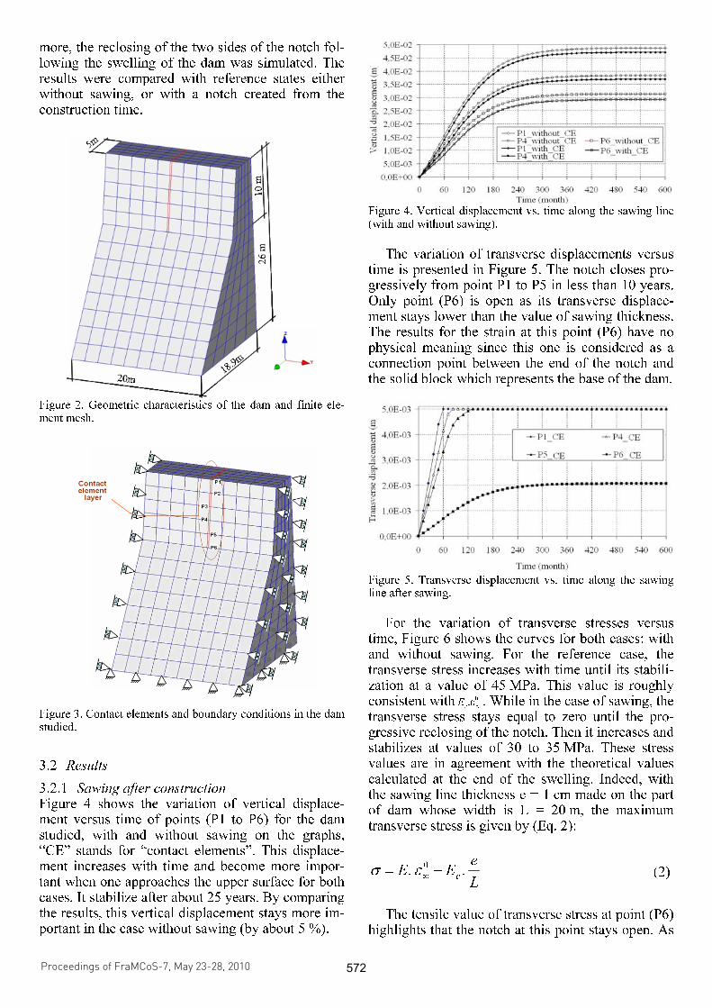
for the strain simulations, this local stress value has no physical meaning since it corresponds to singular connection of contact and solid elements.
Figure 6. Transverse stress vs. time along the sawing line with and without sawing.
3.2.2 Sawing after 10 years Figure 7 shows the variation of vertical displace-ment versus time of points (P1 to P6) belonging to the sawing line. Before sawing, the vertical dis-placements correspond to Figure 4. After sawing (af-ter 10 years of the structure life), the displacements decrease instantaneously and increase again but stay about 5 % lower than the vertical displacements of reference case (without sawing).
Figure 7. Vertical displacement vs. time along the sawing line before and after sawing.
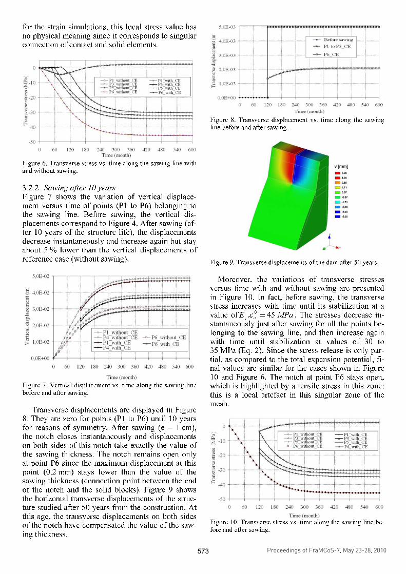
Transverse displacements are displayed in Figure
8. They are zero for points (P1 to P6) until 10 years for reasons of symmetry. After sawing (e = 1 cm), the notch closes instantaneously and displacements on both sides of this notch take exactly the value of the sawing thickness. The notch remains open only at point P6 since the maximum displacement at this point (0.2 mm) stays lower than the value of the sawing thickness (connection point between the end of the notch and the solid blocks). Figure 9 shows the horizontal transverse displacements of the struc-ture studied after 50 years from the construction. At this age, the transverse displacements on both sides of the notch have compensated the value of the saw-ing thickness.
Figure 8. Transverse displacement vs. time along the sawing line before and after sawing.
Figure 9. Transverse displacements of the dam after 50 years.
Moreover, the variations of transverse stresses versus time with and without sawing are presented in Figure 10. In fact, before sawing, the transverse stress increases with time until its stabilization at a value of MPaE
c45.
0=
∞ε . The stresses decrease in-
stantaneously just after sawing for all the points be-longing to the sawing line, and then increase again with time until stabilization at values of 30 to 35 MPa (Eq. 2). Since the stress release is only par-tial, as compared to the total expansion potential, fi-nal values are similar for the cases shown in Figure 10 and Figure 6. The notch at point P6 stays open, which is highlighted by a tensile stress in this zone: this is a local artefact in this singular zone of the mesh.
Figure 10. Transverse stress vs. time along the sawing line be-fore and after sawing.
Proceedings of FraMCoS-7, May 23-28, 2010
hThD ∇−= ),(J (1)
The proportionality coefficient D(h,T) is called moisture permeability and it is a nonlinear function of the relative humidity h and temperature T (Bažant & Najjar 1972). The moisture mass balance requires that the variation in time of the water mass per unit volume of concrete (water content w) be equal to the divergence of the moisture flux J
J•∇=∂
∂−
t
w (2)
The water content w can be expressed as the sum
of the evaporable water we (capillary water, water vapor, and adsorbed water) and the non-evaporable (chemically bound) water wn (Mills 1966, Pantazopoulo & Mills 1995). It is reasonable to assume that the evaporable water is a function of relative humidity, h, degree of hydration, αc, and degree of silica fume reaction, αs, i.e. we=we(h,αc,αs) = age-dependent sorption/desorption isotherm (Norling Mjonell 1997). Under this assumption and by substituting Equation 1 into Equation 2 one obtains
nscw
s
ew
c
ew
hh
Dt
h
h
ew
&&& ++∂
∂
∂
∂
=∇•∇+∂
∂
∂
∂
− αα
αα
)(
(3)
where ∂we/∂h is the slope of the sorption/desorption isotherm (also called moisture capacity). The governing equation (Equation 3) must be completed by appropriate boundary and initial conditions.
The relation between the amount of evaporable water and relative humidity is called ‘‘adsorption isotherm” if measured with increasing relativity humidity and ‘‘desorption isotherm” in the opposite case. Neglecting their difference (Xi et al. 1994), in the following, ‘‘sorption isotherm” will be used with reference to both sorption and desorption conditions. By the way, if the hysteresis of the moisture isotherm would be taken into account, two different relation, evaporable water vs relative humidity, must be used according to the sign of the variation of the relativity humidity. The shape of the sorption isotherm for HPC is influenced by many parameters, especially those that influence extent and rate of the chemical reactions and, in turn, determine pore structure and pore size distribution (water-to-cement ratio, cement chemical composition, SF content, curing time and method, temperature, mix additives, etc.). In the literature various formulations can be found to describe the sorption isotherm of normal concrete (Xi et al. 1994). However, in the present paper the semi-empirical expression proposed by Norling Mjornell (1997) is adopted because it
explicitly accounts for the evolution of hydration reaction and SF content. This sorption isotherm reads
( ) ( )( )
( ) ( )⎥⎥
⎦
⎤
⎢⎢
⎣
⎡
⎥⎥⎥
⎦
⎤
⎢⎢⎢
⎣
⎡
−
−∞
+
−∞
−=
1110
,1
110
11,
1,,
hcc
ge
scK
hcc
ge
scG
sch
ew
αα
αα
αα
αααα
(4)
where the first term (gel isotherm) represents the physically bound (adsorbed) water and the second term (capillary isotherm) represents the capillary water. This expression is valid only for low content of SF. The coefficient G1 represents the amount of water per unit volume held in the gel pores at 100% relative humidity, and it can be expressed (Norling Mjornell 1997) as
( ) ss
s
vgkc
c
c
vgk
scG αααα +=,1
(5)
where k
cvg and k
svg are material parameters. From the
maximum amount of water per unit volume that can fill all pores (both capillary pores and gel pores), one can calculate K1 as one obtains
( )1
110
110
11
22.0188.00
,1
−⎟⎠
⎞⎜⎝
⎛−∞
⎥⎥⎥
⎦
⎤
⎢⎢⎢
⎣
⎡⎟⎠
⎞⎜⎝
⎛−∞
−−+−
=
hcc
ge
hcc
geGs
ssc
w
scK
αα
αα
αα
αα
(6)
The material parameters k
cvg and k
svg and g1 can
be calibrated by fitting experimental data relevant to free (evaporable) water content in concrete at various ages (Di Luzio & Cusatis 2009b).
2.2 Temperature evolution
Note that, at early age, since the chemical reactions associated with cement hydration and SF reaction are exothermic, the temperature field is not uniform for non-adiabatic systems even if the environmental temperature is constant. Heat conduction can be described in concrete, at least for temperature not exceeding 100°C (Bažant & Kaplan 1996), by Fourier’s law, which reads
T∇−= λq (7)
where q is the heat flux, T is the absolute temperature, and λ is the heat conductivity; in this
4 SIMULATION OF PROGRESSIVE CRACKING
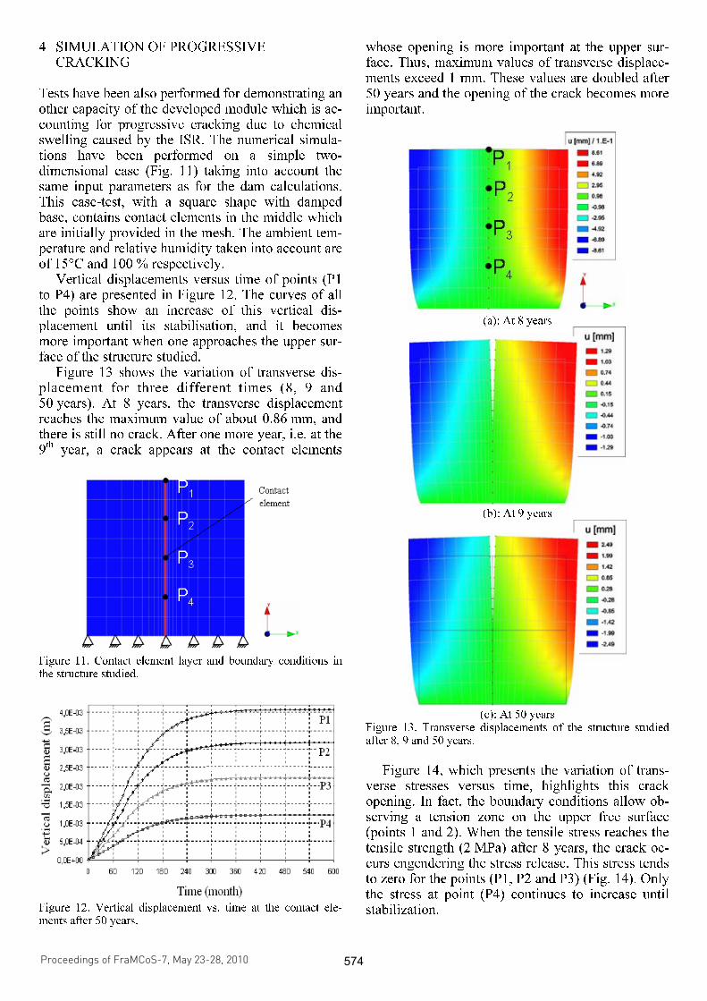
Tests have been also performed for demonstrating an other capacity of the developed module which is ac-counting for progressive cracking due to chemical swelling caused by the ISR. The numerical simula-tions have been performed on a simple two-dimensional case (Fig. 11) taking into account the same input parameters as for the dam calculations. This case-test, with a square shape with damped base, contains contact elements in the middle which are initially provided in the mesh. The ambient tem-perature and relative humidity taken into account are of 15°C and 100 % respectively.
Vertical displacements versus time of points (P1 to P4) are presented in Figure 12. The curves of all the points show an increase of this vertical dis-placement until its stabilisation, and it becomes more important when one approaches the upper sur-face of the structure studied.
Figure 13 shows the variation of transverse dis-placement for three different times (8, 9 and 50 years). At 8 years, the transverse displacement reaches the maximum value of about 0.86 mm, and there is still no crack. After one more year, i.e. at the 9th
year, a crack appears at the contact elements
Figure 11. Contact element layer and boundary conditions in the structure studied.
Figure 12. Vertical displacement vs. time at the contact ele-ments after 50 years.
whose opening is more important at the upper sur-face. Thus, maximum values of transverse displace-ments exceed 1 mm. These values are doubled after 50 years and the opening of the crack becomes more important.
(a): At 8 years
(b): At 9 years
(c): At 50 years
Figure 13. Transverse displacements of the structure studied after 8, 9 and 50 years.
Figure 14, which presents the variation of trans-
verse stresses versus time, highlights this crack opening. In fact, the boundary conditions allow ob-serving a tension zone on the upper free surface (points 1 and 2). When the tensile stress reaches the tensile strength (2 MPa) after 8 years, the crack oc-curs engendering the stress release. This stress tends to zero for the points (P1, P2 and P3) (Fig. 14). Only the stress at point (P4) continues to increase until stabilization.
Proceedings of FraMCoS-7, May 23-28, 2010
hThD ∇−= ),(J (1)
The proportionality coefficient D(h,T) is called moisture permeability and it is a nonlinear function of the relative humidity h and temperature T (Bažant & Najjar 1972). The moisture mass balance requires that the variation in time of the water mass per unit volume of concrete (water content w) be equal to the divergence of the moisture flux J
J•∇=∂
∂−
t
w (2)
The water content w can be expressed as the sum
of the evaporable water we (capillary water, water vapor, and adsorbed water) and the non-evaporable (chemically bound) water wn (Mills 1966, Pantazopoulo & Mills 1995). It is reasonable to assume that the evaporable water is a function of relative humidity, h, degree of hydration, αc, and degree of silica fume reaction, αs, i.e. we=we(h,αc,αs) = age-dependent sorption/desorption isotherm (Norling Mjonell 1997). Under this assumption and by substituting Equation 1 into Equation 2 one obtains
nscw
s
ew
c
ew
hh
Dt
h
h
ew
&&& ++∂
∂
∂
∂
=∇•∇+∂
∂
∂
∂
− αα
αα
)(
(3)
where ∂we/∂h is the slope of the sorption/desorption isotherm (also called moisture capacity). The governing equation (Equation 3) must be completed by appropriate boundary and initial conditions.
The relation between the amount of evaporable water and relative humidity is called ‘‘adsorption isotherm” if measured with increasing relativity humidity and ‘‘desorption isotherm” in the opposite case. Neglecting their difference (Xi et al. 1994), in the following, ‘‘sorption isotherm” will be used with reference to both sorption and desorption conditions. By the way, if the hysteresis of the moisture isotherm would be taken into account, two different relation, evaporable water vs relative humidity, must be used according to the sign of the variation of the relativity humidity. The shape of the sorption isotherm for HPC is influenced by many parameters, especially those that influence extent and rate of the chemical reactions and, in turn, determine pore structure and pore size distribution (water-to-cement ratio, cement chemical composition, SF content, curing time and method, temperature, mix additives, etc.). In the literature various formulations can be found to describe the sorption isotherm of normal concrete (Xi et al. 1994). However, in the present paper the semi-empirical expression proposed by Norling Mjornell (1997) is adopted because it
explicitly accounts for the evolution of hydration reaction and SF content. This sorption isotherm reads
( ) ( )( )
( ) ( )⎥⎥
⎦
⎤
⎢⎢
⎣
⎡
⎥⎥⎥
⎦
⎤
⎢⎢⎢
⎣
⎡
−
−∞
+
−∞
−=
1110
,1
110
11,
1,,
hcc
ge
scK
hcc
ge
scG
sch
ew
αα
αα
αα
αααα
(4)
where the first term (gel isotherm) represents the physically bound (adsorbed) water and the second term (capillary isotherm) represents the capillary water. This expression is valid only for low content of SF. The coefficient G1 represents the amount of water per unit volume held in the gel pores at 100% relative humidity, and it can be expressed (Norling Mjornell 1997) as
( ) ss
s
vgkc
c
c
vgk
scG αααα +=,1
(5)
where k
cvg and k
svg are material parameters. From the
maximum amount of water per unit volume that can fill all pores (both capillary pores and gel pores), one can calculate K1 as one obtains
( )1
110
110
11
22.0188.00
,1
−⎟⎠
⎞⎜⎝
⎛−∞
⎥⎥⎥
⎦
⎤
⎢⎢⎢
⎣
⎡⎟⎠
⎞⎜⎝
⎛−∞
−−+−
=
hcc
ge
hcc
geGs
ssc
w
scK
αα
αα
αα
αα
(6)
The material parameters k
cvg and k
svg and g1 can
be calibrated by fitting experimental data relevant to free (evaporable) water content in concrete at various ages (Di Luzio & Cusatis 2009b).
2.2 Temperature evolution
Note that, at early age, since the chemical reactions associated with cement hydration and SF reaction are exothermic, the temperature field is not uniform for non-adiabatic systems even if the environmental temperature is constant. Heat conduction can be described in concrete, at least for temperature not exceeding 100°C (Bažant & Kaplan 1996), by Fourier’s law, which reads
T∇−= λq (7)
where q is the heat flux, T is the absolute temperature, and λ is the heat conductivity; in this
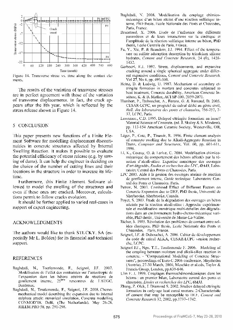
Figure 14. Transverse stress vs. time along the contact ele-ments.
The results of the variation of transverse stresses
are in perfect agreement with those of the variation of transverse displacements. In fact, the crack ap-pears after the 8th year, which is reflected by the stress release shown in Figure 14.
5 CONCLUSION
This paper presents new functions of a Finite Ele-ment Software for modelling displacement disconti-nuities in concrete structures affected by Internal Swelling Reaction. It makes it possible to evaluate the potential efficiency of stress release (e.g. by saw-ing of dams). It can help the engineer in deciding on the choice of the number of cutting lines and their locations in the structure in order to increase its life-time.
Furthermore, this Finite Element Software al-lowed to model the swelling of the structures and even if these ones are cracked. Moreover, calcula-tions permit to follow cracks evolution.
It should be further applied to varied real-cases in support of expert engineering.
ACKNOWLEDGMENTS
The authors would like to thank STUCKY. SA (es-pecially Mr L. Boldea) for its financial and technical support.
REFERENCES
Baghdadi, N., Toutlemonde, F., Seignol, J.F. 2007. Modélisation de l’effet des contraintes sur l’anisotropie de l’expansion dans les bétons atteints de réactions de gonflement interne, 25ème rencontres de l’AUGC, Bordeaux.
Baghdadi, N., Toutlemonde, F., Seignol, J.F. 2008. Chemo-mechanical model describing the expansion due to internal sulphate attack: numerical simulation, Concrete modelling CONMOD’08, Delft, (The Netherlands), May 26-28, RILEM PRO 58, pp. 291-298.
Baghdadi, N. 2008. Modélisation du couplage chimico-mécanique d’un béton atteint d’une réaction sulfatique in-terne, PhD thesis, Ecole Nationale des Ponts et Chaussées, Paris, France.
Brunetaud, X. 2006. Etude de l’influence des différents paramètres et de leurs interactions sur la cinétique et l’amplitude de la réaction sulfatique interne au béton, PhD thesis, Ecole Centrale de Paris, France.
Fu, Y., Xie, P. & Beaudoin, J.J. 1994. Effect of the tempera-ture on sulfate adsorption desorption by tricalcium silicate hydrates, Cement and Concrete Research, 24 (8), 1428-1432.
Garboczi, E.J. 1997. Stress, displacements, and expansive cracking around a single spherical aggregate under differ-ent expansive conditions, Cement and Concrete Research, Vol 27, No 4, pp. 495-500.
Heinz, D. & Ludwig, U. 1987. Mechanism of secondary et-tringite formation in mortars and concretes subjected to heat treatment, Concrete durability, American Concrete In-stitute, K. & B. Mather, ACI SP-100, 2059-2071.
Humbert, P., Dubouchet, A., Fezans, G. & Remaud, D. 2005. CESAR-LCPC, un progiciel de calcul dédié au génie civil, Bull. des laboratoires des ponts et chaussées, 256-257, 7-37, LCPC, Paris.
Lawrence., C.D. 1995. Delayed ettringite formation: an issue? Material Science of Concrete. (ed. J. Skalny & S. Mindess), pp. 113-154 American Ceramic Society, Westerville, OH, USA.
Léger, P., Cote, P., Tinawir, R. 1996. Finite element analysis of concrete swelling due to Alkali-Aggregate Reaction in Dams, Computer and Structures, Vol. 60, pp. 601-611, 1996.
Li, K., Coussy, O. & Larive, C. 2004. Modélisation chimico-mécanique du comportement des bétons affectés par la ré-action d’alcali-silice. Expertise numérique des ouvrages d’art dégradés, Etudes et recherches des LPC, OA43, Labo-ratoire Central des Ponts et Chaussées, Paris.
LPC 2003. Aide à la gestion des ouvrages atteints de réaction de gonflement interne, Guide technique, Laboratoire Cen-tral des Ponts et Chaussées, Paris.
Petrov, N. 2003. Combined Effect of Different Factors on Concrete Expansion due to DEF, PhD thesis, Université de Sherbrooke, Sherbrooke, Canada.
Poyet, S. 2003. Etude de la dégradation des ouvrages en béton atteints par la réaction alcali-silice : Approche expérimen-tale et modélisation numérique multi-échelles des dégrada-tions dans un environnement hydro-chemo-mécanique vari-able, PhD thesis , Université de Marne-La-Vallée.
Richer, S. 1985. Résolution des problèmes de contact entre sol-ides élastiques, PhD thesis, Ecole Nationale des Ponts et Chaussées, Paris, France.
Seignol, J.F. & Dubouchet, A. 2006. Cahier de développement du code de calcul ALKA, CESAR-LCPC version recher-che, LCPC.
Seignol J.F., Ngo, T.T., Toutlemonde F. 2006. Modeling of the coupling between moisture and alkali-silica reaction in concrete. - "Computational Modeling of Concrete Struc-tures", proceedings of Euro-C 2006 conference, Mayrhofen (Austria), 27-30 March, 2006, Meschke et al.eds, Taylor & Francis Group, London, pp.639-646.
Ulm F. J. 1999. Couplages thermochémomécaniques dans les bétons : un premier bilan, Laboratoire central des ponts et chaussées, Etudes et recherches des LPC, OA31.
Zhang, Z. Olek, J. Diamond S. 2002. Studies delayed ettringite formation in early-age heat cured mortars: 2-Characteristic of cement that may be susceptible to DEF. Cement and Concrete Research 32, 2002, pp.1737–1742.
Proceedings of FraMCoS-7, May 23-28, 2010
hThD ∇−= ),(J (1)
The proportionality coefficient D(h,T) is called moisture permeability and it is a nonlinear function of the relative humidity h and temperature T (Bažant & Najjar 1972). The moisture mass balance requires that the variation in time of the water mass per unit volume of concrete (water content w) be equal to the divergence of the moisture flux J
J•∇=∂
∂−
t
w (2)
The water content w can be expressed as the sum
of the evaporable water we (capillary water, water vapor, and adsorbed water) and the non-evaporable (chemically bound) water wn (Mills 1966, Pantazopoulo & Mills 1995). It is reasonable to assume that the evaporable water is a function of relative humidity, h, degree of hydration, αc, and degree of silica fume reaction, αs, i.e. we=we(h,αc,αs) = age-dependent sorption/desorption isotherm (Norling Mjonell 1997). Under this assumption and by substituting Equation 1 into Equation 2 one obtains
nscw
s
ew
c
ew
hh
Dt
h
h
ew
&&& ++∂
∂
∂
∂
=∇•∇+∂
∂
∂
∂
− αα
αα
)(
(3)
where ∂we/∂h is the slope of the sorption/desorption isotherm (also called moisture capacity). The governing equation (Equation 3) must be completed by appropriate boundary and initial conditions.
The relation between the amount of evaporable water and relative humidity is called ‘‘adsorption isotherm” if measured with increasing relativity humidity and ‘‘desorption isotherm” in the opposite case. Neglecting their difference (Xi et al. 1994), in the following, ‘‘sorption isotherm” will be used with reference to both sorption and desorption conditions. By the way, if the hysteresis of the moisture isotherm would be taken into account, two different relation, evaporable water vs relative humidity, must be used according to the sign of the variation of the relativity humidity. The shape of the sorption isotherm for HPC is influenced by many parameters, especially those that influence extent and rate of the chemical reactions and, in turn, determine pore structure and pore size distribution (water-to-cement ratio, cement chemical composition, SF content, curing time and method, temperature, mix additives, etc.). In the literature various formulations can be found to describe the sorption isotherm of normal concrete (Xi et al. 1994). However, in the present paper the semi-empirical expression proposed by Norling Mjornell (1997) is adopted because it
explicitly accounts for the evolution of hydration reaction and SF content. This sorption isotherm reads
( ) ( )( )
( ) ( )⎥⎥
⎦
⎤
⎢⎢
⎣
⎡
⎥⎥⎥
⎦
⎤
⎢⎢⎢
⎣
⎡
−
−∞
+
−∞
−=
1110
,1
110
11,
1,,
hcc
ge
scK
hcc
ge
scG
sch
ew
αα
αα
αα
αααα
(4)
where the first term (gel isotherm) represents the physically bound (adsorbed) water and the second term (capillary isotherm) represents the capillary water. This expression is valid only for low content of SF. The coefficient G1 represents the amount of water per unit volume held in the gel pores at 100% relative humidity, and it can be expressed (Norling Mjornell 1997) as
( ) ss
s
vgkc
c
c
vgk
scG αααα +=,1
(5)
where k
cvg and k
svg are material parameters. From the
maximum amount of water per unit volume that can fill all pores (both capillary pores and gel pores), one can calculate K1 as one obtains
( )1
110
110
11
22.0188.00
,1
−⎟⎠
⎞⎜⎝
⎛−∞
⎥⎥⎥
⎦
⎤
⎢⎢⎢
⎣
⎡⎟⎠
⎞⎜⎝
⎛−∞
−−+−
=
hcc
ge
hcc
geGs
ssc
w
scK
αα
αα
αα
αα
(6)
The material parameters k
cvg and k
svg and g1 can
be calibrated by fitting experimental data relevant to free (evaporable) water content in concrete at various ages (Di Luzio & Cusatis 2009b).
2.2 Temperature evolution
Note that, at early age, since the chemical reactions associated with cement hydration and SF reaction are exothermic, the temperature field is not uniform for non-adiabatic systems even if the environmental temperature is constant. Heat conduction can be described in concrete, at least for temperature not exceeding 100°C (Bažant & Kaplan 1996), by Fourier’s law, which reads
T∇−= λq (7)
where q is the heat flux, T is the absolute temperature, and λ is the heat conductivity; in this