int-150 om 160814 - studio 22 · in installation, by providing for ... “aleph”, and “zen”...
TRANSCRIPT

1INT-150 Owners Manual
PASSTM
INT-150 Owner’s ManualJuly, 2015

2INT-150 Owners Manual
Please keep these instructions and heed all warnings.Use product only for intended function.
For your protection please read the following:
Water and moisture: Electrical devices should not be used near water (as per example, near a bathtub, washbasin, kitchen sink, laundry tub, wet basement or swimming pool. ) Care should be taken such that objects do not have the opportunity to fall, and that liquid is never spilled onto or into the device enclosure through openings.
Power Sources: An electrical device must be connected to a mains power source in strict accordance with the supplied product owners manual. Please verify that the AC mains voltage specified in the product manual match those requirements indicated on the unit and the AC voltage provided to your location by the power company. Unplug this apparatus during lightening storms or when unused for long periods of time. To completely disconnect this apparatus from mains power, disconnect the power cord from the AC receptacle. The equipment power switch does not provide adequate protection to be considered a service disconnect.
Grounding: Adequate precautions should be taken so that the grounding provisions built into an electrical product are never defeated.
Power Cords: Pass Labs provides a power supply cord that meets all legislated requirements for the market in which the product was originally sold. If you choose to substitute an after-market product we urge you to choose a polarized cord that is fully safety rated by the necessary local authority. Under no circumstances defeat the safety purpose of any polarized plugs. If the supplied power cord does not fit your power outlet; consult a qualified electrician, never modify the plug.
Power Cord Protection: Power supply cords should be routed so that they are not likely to be walked on, abraded, or pinched by items placed on or against them, paying particular attention to cords where they enter plugs or exit from a device. Never under any circumstance insert a cut or damaged power cord into a mains power socket.
Power and Signal: Cables should never be connected / disconnected with equipment powered up. Failure to heed this warning may cause injury, damage or destroy equipment.
Ventilation: Power-amplifiers run hot, but you should be able to place your hands on them without discomfort. You must allow for this heat in installation, by providing for free air circulation around the product. Electronics should not be subjected to sources of excessive radiant heat. Excessive heat can shorten the life of the product and may cause the electronics to self protect and shut down. Never block any ventilation openings. Allow at least 6 inches of clearance around these products for proper ventilation.
WARNING

3INT-150 Owners Manual
Crush and Tip Hazard: When moving or placing these products use caution to avoid injury from tip-over or fall. Make sure that any stand, cart, table, bracket or tripod used to support this product is weight rated sufficient to the task.
Servicing: To reduce the risk of fire, electrical shock or other injuries, the user should not attempt to service the device beyond that which is described in the operating instructions. All other servicing must be referred to qualified service personnel.
For Units With Externally Accessible Fuse Receptacle: Unplug the device from all sources of power before changing or inspecting any fuse. Replace fuse with one of same physical size, type and rating as that specified by the manufacture for that product.
Pass Laboratories13395 New Airport Rd., Ste. G
Auburn, CA 95602
www.passlabs.com
tel: (530) 878 5350
fax: (530) 878 5358
“Pass”, “PASS”, “Pass Labs”, “Pass Laboratories”, Supersymmetery”, “Aleph”, and “Zen” and are all registered trademarks of Pass Laboratories, Inc., and all rights thereto are protected by law.

4INT-150 Owners Manual
Nelson Pass has been designing audio electronics professionally since about 1971, first with ESS (remember Heil Air Motion transformers?), and then forming a new company, Threshold in 1975. Threshold pioneered the design of high power Class A power amplifiers and later, high power amplifiers using only local feedback (the Stasis series).
Pass sold Threshold and created Pass Laboratories in 1991, where he concentrated first on elevating single-ended Class A power amplifiers to new power levels and performance, the Aleph series.
Along the way he found the time to design highly successful lines of amplifiers for such companies as Adcom and Nakamichi, and has contributed approximately 60 designs (so far) to the public “Do-It-Yourself ” audio hobbyist community.
Over the years, Nelson Pass has made power, simplicity, and performance his design signatures. The hardware tends to run heavy and hot, but elicits high performance and reliability from simple circuits with little or no negative feedback.
In 1998 Pass Labs released the X series of audio power amplifiers, based on the trademarked “SuperSymmetric” topology (U.S. Patent #5,376,899), which elicits high power and performance from simple circuits with minimal feedback.
The first X amplifier, the X1000 was intended as the premier example of the power of this principle, delivering 1000 watts rms into 8 ohms at low distortion. By itself of course, this is no miracle, but you have to consider that products with comparable performance have complicated circuits with as many as nine consecutive gain stages and lots and lots of negative feedback. The X1000 had only two stages and used only minimal local feedback.
The difference was the unique balanced circuit topology in which circuit errors are replicated at both output terminals so as to cancel and disappear across the loudspeaker terminals. The high quality of the sound reflects both the low distortion and simplicity of the gain path.
The SuperSymmetric circuit consists of two identical matched circuits arranged like the wings of a butterfly, showing symmetry from left to right, and operating balanced to the loudspeaker. The amplified signal appears with opposing phase and equal potential across the loudspeaker. Most of the distortion and noise appears in phase across the loudspeaker, and is not seen.
We start with simple FET circuits already having low distortion and noise, and arrange them in two symmetrical halves. The two halves of the amplifier channel are closely matched, eliminating a large portion of distortion and noise without feedback. A small amount of feedback is also applied, not so much for the purpose of reducing distortion but to make
Introduction

5INT-150 Owners Manual
the distortion as identical as possible on both polarities of the balanced output.
It is easier to make distortions in the two halves more identical than to remove them with feedback, and this is the operating principle of X amplifiers.
Since the X1000, Pass Labs products have continuously evolved toward higher performance. The Class AB “X” series was joined by the Class A “XA” amplifiers. Subsequent improvements to the Class AB “X” amplifiers resulted in the “X.5” products, and their phenomenal success has led to the Class A “XA.5” series.
As always the goal has been the best musical and objective performance possible with minimal parts in the signal path and minimal feedback. This process is not completely quantified, and many of the improvements are the result of trial and error and extensive listening.
Measurement of performance is important to us, and we feel that well-designed product sounds good and measures good. Apparently it is possible to make an amplifier which measures well but which does not please the ears, and so we let our ears be the final judge.
The X amplifiers deliver more output power per dollar, and the XA amplifiers have a better subjective performance. All of the amplifiers drive known loudspeaker loads without misbehaving, and all are unconditionally stable into low impedance and reactive loads.
All the usual performance metrics - power, distortion, noise, input impedance, damping factor and bandwidth have all been improved in this latest generation. The power supplies are larger, with fast rectifiers gating to larger capacitor banks. The increases in AC line noise worldwide have been addressed with heavier EMI filtering and dramatically quieter power transformers. In addition, through improved biasing regulation, the circuits give much more consistent performance under varying AC line voltages and over a variety of ambient temperatures.
All this is very nice, but only if it improves your listening experience. We listen very carefully and critically to our amplifiers with a wide variety of associated equipment and we take our time with it. Musical performance is most important, and is the basis of our success over the years.
It’s true that we also value the other things. The design and manufacturing decisions have to balance subjective performance against reliability, cost, specs, and ego (in approximately that order). That is why we make more than one amplifier, but all are built with the same commitment to quality.
The Pass Laboratories INT-150 Integrated Amplifier was designed specifically to bridge the gap between so called high-end audiophile product and the need for a simple “no nonsense”, convenient, user-friendly, high

6INT-150 Owners Manual
satisfaction audio product. From a measured and subjective viewpoint this is an outstanding product, we trust you will sit back and listen with a big grin on your face.
If you have purchased this amplifier, we thank you for your confidence, and hope that you enjoy it for many years. If you need product service, have any questions or comments, or if we can help you with your audio system, please don’t hesitate to contact us.
X topology amplifiers run at about the same power as their output rating, and a large part of that energy gets dissipated across the heat sinks. Expect the heat sinks on the side of the amplifier run hot to the touch – about 25 to 30 degrees C. above ambient, so you can expect 50 to 55 degrees C. temperatures on the heat sinks. It is very important to the long life of the amplifier that they get good ventilation.
You can put this amplifier anywhere you wish, but it must have good ventilation to properly cool. Do not place this product in enclosed cabinets or small closets without means for air to circulate freely. Stacking these power amplifiers directly upon each other is not recommended for the same reason. You should have a minimum of about 6 inches clearance to the top and sides for adequate air circulation. Never block any ventilation openings in the chassis. Never expose this product or it’s remote control to excessive heat sources, such as domestic heaters or open fires. Keep all electrical devices away from liquids, and liquids away from electrical devices.
When not actually intending to play music the amplifier should be left in standby mode from the front panel switch, where it draws only a few watts of bias on the output stage. If you wish to reduce the power draw to 0, you can shut the amplifier off via the rear panel switch, however we recommend that for minimum noise at the loudspeaker this switch should be toggled in stand-by mode, only. If you are not going to use this product for an extended period of time or if you are expecting an atmospheric electrical disturbance (lightening storm) un-plug it. We have provided a standard IEC polarized power cord that fits into the standard 15 amp IEC receptacle at the rear of the amplifier chassis.
Given the character of these amplifiers current draw, we generally do not recommend active line conditioners, although they are unlikely to damage the amplifier. Save your line conditioner for the low level components, like your cd player.
This amplifier is equipped for operation with an earth ground provided by the users AC outlet. Never defeat this ground connection or the polarized plug of the power cord. The signal ground of this amplifier is connected to earth through a power thermistor, which provides a safety ground but provides isolation from system ground loops. Should your audio system have a device that requires an additional signal ground you will find that ground on the rear of the INT-150 at the white binding post which is marked “Signal Gnd”.
Setup

7INT-150 Owners Manual
1) Vacuum Florescent display ; shows operational status.2) Mute, indicator (Blue LED)3) Stand-by Power on, indicator (Blue LED)4) Stand-by Power on, momentary push button (on / off)5) Mute, momentary push-button (on / off)6) Input selection buttons (inputs 1-4)7) IR remote, receiver window8) Volume control
A) Pre-amplifier inputs (1&2 XLR/RCA , 3&4 RCA)B) Pre-amplifier outputs (XLR OR RCA)C) Right Channel speaker connectorD) Signal ground connectorE) IEC 520 AC power inlet moduleF) Main Power switch (not a safety disconnect)G) Fuse holder H) Left Channel Speaker connector
8INT-150 Owners Manual
For maximum safety we suggest that the power cord should be the last cable installed on your power-amplifier.
You may, if you wish, substitute a 15-amp aftermarket power cord for the one we have supplied. Only use polarized power cords, which meet all local safety standards and carry acceptance marks from the local regulatory authority. The power cord should be attached to the amplifier prior to plugging into house power. Always place the rear-mounted switch in the off (down) position before plugging in this amplifier.
The amplifier’s voltage and current rating are indicated on the rear panel. It will be indicated as either 100 volts, 120 volts, 220 volts, 230 volts or 240 volts. The smaller Pass Laboratories power amplifiers, preamps and integrated amplifiers use a slow-blow 3AG (equivalent to 313 in EC markets) type fuse. The required value of the fuse will be indicated on the amplifier. The frequency rating of the AC line source is 50 to 60 Hz. Please verify that the amplifiers indicated voltage requirements are consistent with the supplied voltage and current at your location.
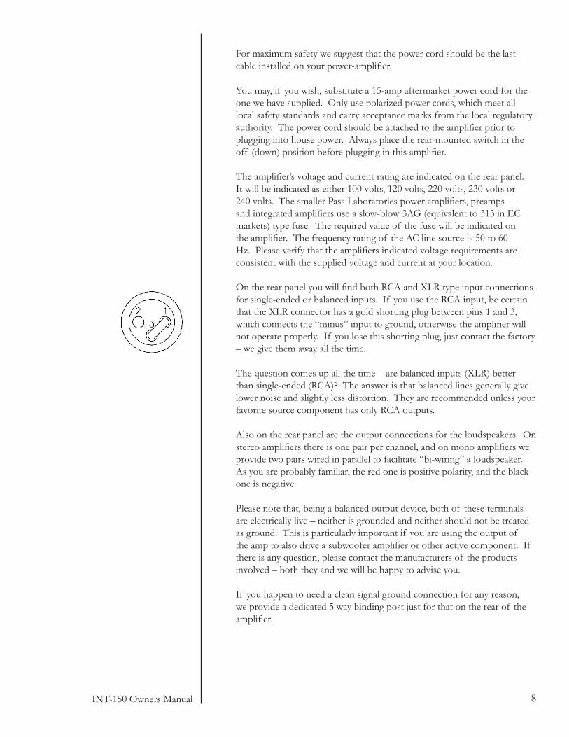
On the rear panel you will find both RCA and XLR type input connections for single-ended or balanced inputs. If you use the RCA input, be certain that the XLR connector has a gold shorting plug between pins 1 and 3, which connects the “minus” input to ground, otherwise the amplifier will not operate properly. If you lose this shorting plug, just contact the factory – we give them away all the time.
The question comes up all the time – are balanced inputs (XLR) better than single-ended (RCA)? The answer is that balanced lines generally give lower noise and slightly less distortion. They are recommended unless your favorite source component has only RCA outputs.
Also on the rear panel are the output connections for the loudspeakers. On stereo amplifiers there is one pair per channel, and on mono amplifiers we provide two pairs wired in parallel to facilitate “bi-wiring” a loudspeaker. As you are probably familiar, the red one is positive polarity, and the black one is negative.
Please note that, being a balanced output device, both of these terminals are electrically live – neither is grounded and neither should not be treated as ground. This is particularly important if you are using the output of the amp to also drive a subwoofer amplifier or other active component. If there is any question, please contact the manufacturers of the products involved – both they and we will be happy to advise you.
If you happen to need a clean signal ground connection for any reason, we provide a dedicated 5 way binding post just for that on the rear of the amplifier.

9INT-150 Owners Manual
So the amplifier is sitting there unconnected.
Make sure that the rear panel power switch is off (down). Plug the AC cord into the back of the amplifier, and then into the wall. Then turn the power switch on (up). The lights in your house may dim for a moment as the power supply charges the capacitors.
Please note that this switch is not a “safety device” or “emergency disconnect” for this product. This switch does not provide personal shock protection in the manner of a ground-fault interrupter, nor is it intended to. One more reason why it is important not to defeat the Earth connection of your power cord. Safety or Emergency disconnect involves removing a power cord, we feel that this is the most positive and safest solution.
On the front panel, the “power” LED indicator should be glowing blue, indicating that AC power is available and the capacitor banks are charged. If the “LED” is not glowing blue, then cycle the front panel power button to “on” and turn the volume control just to verify operation.
Now turn off the front and rear power switches and unplug the AC power cord from the wall while you connect the speakers and inputs. Amplifier output terminals and speaker terminals will be electrically live when the amplifier is on.
Check to make certain that the loudspeaker cables aren’t shorted at the loudspeaker end, and then connect speaker cables to the output binding posts on the amplifiers, observing correct polarity. The output binding posts will accept either bare wire or spades. (Regulatory agencies in many countries have banned binding posts that will accept a banana plug, forcing us to abandon this option.) Make sure that your speaker wires only attach to the outputs of the amplifier, not to each other and never to the amplifier case.
Remember the warning about treating the output connections as ground, particularly if you are using a powered subwoofer with this amplifier. If you need a ground, use the one provided specifically on the rear panel of the amplifier.
The amplifier may be driven single-end or balanced, your choice. Single-ended input will always occur through the RCA connector and balanced input will always occur through the XLR connector.
Again, if you drive the amplifier single-ended then leave the supplied jumpers in place between pins 1 & 3 on the input XLR.
On the XLR connector pin 1 is ground, pin two is positive input and pin 3 is inverted (negative) input. Pin numbers are marked on the XLR. If you re-install the jumper incorrectly or leave it lying about, the amplifier will not work properly, and you will be able to tell.

10INT-150 Owners Manual
Choose either XLR or RCA inputs. If you run both at once on a single input from different components, the sound is not likely to be optimal, but it shouldn’t cause damage anywhere. Now that the source components and loudspeakers are connected into the amplifier; plug the power cord back into the wall, and turn on the rear power switch.
Push the front panel power button to activate the amplifier and turn the volume control down (counter clock-wise). The front panel display should now be illuminated.
The controls on the front of the Pass Labs integrated amplifier should be intuitive.
The hand remote has some additional convenience features that the front panel does not. Balance from the remote raises or lowers the speaker volume levels relative to each other. Display provides a choice of normal luminance, reduced luminance or display off. In the display “off ” mode the display will be normally dark, yet will provide reduced luminance for several seconds any time a control function on either the remote or integrated amplifier front panel are activated.
Please note: The hand remote is common to several Pass Labs products, not all of the functions on this remote are applicable to your integrated amplifier. Input 5, tape loop, pass through and external amp on are not applicable to the INT-150, integrated amplifier.
The hand remote has two (2) AAA batteries that can be replaced after the back cover from the remote has been removed. These batteries will need to be changed occasionally.
If you are not comfortable removing the rear cover of the remote and changing batteries, have your dealer change them for you. Batteries may explode if exposed to excessive heat, never leave your remote or any battery powered device in direct sunlight or exposed to excessive heat sources.
With any luck, you can now enter that blissful state of musical nirvana, and we won’t expect you back for a while.
It’s always possible that something may go wrong. If so, don’t get excited. We know It’s really aggravating when a product doesn’t work, but it will get fixed, and often it’s something really simple.
You are ready to play music

11INT-150 Owners Manual
We go to a lot of trouble to make products reliable, and the failure rate of our amplifiers is very low. This is small comfort to the few, but take it easy and give us a call if you have problems.
People are interested in how long it takes for these amplifiers to break in. Depending on the resolution of the rest of your audio chain, you may or may not notice any break in of the amplifier beyond the first few hours of operation. You will very likely notice the difference in sonic character between cold and normal operating temperature over the first hour, so we recommend letting these amplifiers warm up before any serious listening.
This generation of amplifiers warms up faster and is more bias-stable during warm up than previous versions, but we still recommend an hour for critical listening. At the factory we adjust the bias and offset values initially and then after warm-up and then again after 48 hours, if necessary. The “sweet spot” is a sink temperature between 50 and 55 degrees C., but this is not critical, and will vary with your room temperature. You should be able to put your hands on the heat sinks without undue discomfort for 5 seconds or so.
The amplifier has a thermal cutout that will disconnect AC power if the temperature exceeds 75 degrees Centigrade. This thermal cutout should never occur in real life. This is a very rare occurrence, and would indicate a serious problem.
We have a general recommendation about interconnects, and speaker cables: They should cost less than the amplifier, and contain at least some conductive material. We have tried a lot of products and most work well, but as a practical matter we cannot make blanket recommendations as to your purchase of cables. Under all circumstances you should unplug power cords before changing signal cables…. you’ve been warned!
The amplifier is not sensitive to source interconnects. It is also not sensitive to radio frequency pickup, which allows some flexibility in choosing source interconnects without shields, though shields are usually a very good idea. For long runs balanced cables are highly recommended for their inherent rejection of noise.
We prefer speaker cables that are short and stout. Oxygen-free copper and silver are the suggested materials. If you find any really exceptional cable made of gold, please gift us a couple hundred meters.
Fortunately this amplifier is not sensitive to the capacitive/inductive character of some of the specialty speaker cables, so feel free to experiment.
We have found that about 90 per cent of bad sounding cables are really bad sounding connections, and we recommend that attention be paid to cleanliness of electrical contact surfaces and proper connector fit.
Speaker Interface

12INT-150 Owners Manual
Speaker cables should be firmly tightened down at the speaker output terminals, but not with a wrench. Output terminals will not withstand the levels of torque that may be easily applied by wrench. Hand tightening without excessive force is plenty. Cleaning contact surfaces with one of the commercially available electronic contact cleaners should be part of your annual system maintenance.
So how long should this hardware last? It is our experience that, barring abuse or the odd failure of a component, the first things to go will be the power supply capacitors, and from experience, they will last 15 to 30 years. Fortunately they die gracefully and are easily replaced by a good technician.
After that, the longevity will depend upon the number of operating thermal cycles, but we can say that we have had amplifiers operating in the field in excess of 20 years with no particular mortality, and we don’t have good information beyond that.
More to the point, you should not worry about it. This is a conservatively built industrial design, not a frail tube circuit run on the brink of catastrophic failure. If it breaks, we will simply get it fixed, so sleep well.
Product Life

13INT-150 Owners Manual
Please check with the factory-authorized distributor in the country you are purchasing this product for specific warranty information.
All Pass Laboratories products purchased from an authorized Pass Labora-tories dealer in North America are covered by a transferable, limited 3-year warranty. This warrantee includes all parts and labor charges incurred at the repair facility in addition to return shipping to the domestic customer, exclu-sive of subsequent damages. Damage due to physical abuse is specifically not covered under this warranty.
For this warranty to apply the customer is responsible for returning the product unmodified to the factory within the warranty period. The customer assumes all responsibility for shipping and insurance to the factory or a fac-tory specified repair facility. The conditions and stipulations of this Pass Laboratories warranty only applies to units sold new in North America.
Non-North America customers should consult with their original Pass Labs dealer or distributor for warrantee repair instruction prior to contacting the factory or shipping product for repair.
Non-North American product must be returned to the country of origin for warrantee service. Foreign distributors are only required to offer warranty service on Pass Laboratories product that they have imported.
Please note: Conditions of warranty service and customer rights for product purchased outside the United States may vary depending upon the distribu-tor and local laws. Please check with your local distributor for specific rights and details.
Any modifications to Pass Laboratories products that have not received written factory approval nullify all claims and void the warrantee. Should a modified product be returned to the factory for repair the owner will be re-quired to pay all necessary charges for the repair in addition to those charges required to return the product to it’s original configuration.
In the case of safety issues, no product shall be returned to the customer without those safety issues being corrected to the most recent accepted standards.
Removal or alteration of original Pass Labs serial numbers voids the factory warranty. Product with altered or missing serial numbers will be suspected as counterfeit product.
Pass Laboratories will not repair or in any way indemnify any counterfeit or cloned product.
Pass Laboratories does not offer products in voltages intended for inter-national markets either to authorized Pass Labs dealers or to third parties
located in the United States or Canada.
Warranty Information
Pass Laboratories, 13395 New Airport Rd., Ste. G., Auburn CA 95602