ht-150 owner’s manual owners manu… · · 2007-12-10ht-150 owner’s manual ... i....
TRANSCRIPT

HT-150 OWNER’S MANUAL
Electrostatic Spraying Systems, Inc.
62 Morrison Street Watkinsville, GA 30677 (706) 769-0025
Revised November 12, 2003
I. Introduction Page 3 II. Warranty 5 III. Safety Precautions 7
• Operators’ Responsibility 7 • Chemical Precautions 7 • Safety Precautions 7 • Decals 8
IV. Initial Installation 9 • Installing the Driveline 9 • Installing the Control Box 9
V. Operating Instructions 9 • Setting the Air Pressure 9 • Setting the Liquid Pressure 9 • Nozzle Adjustment 10 • Turning on Charging 10 • Shutting Down the Sprayer 10
VI. Calibration and Field Operation 10 • Calibration Guide 11
VII. Cleaning and Maintenance 12 • Nozzles 12 • Flushing the Sprayer 13 • Cleaning the Main Tank 13 • Repairing Power Supply Wires 14 • Before Operation 16 • Gear Reducer 16 • Blower 16 • Checking Charge 17 • Vacuum Restrictor 18 • Yearly Maintenance 18
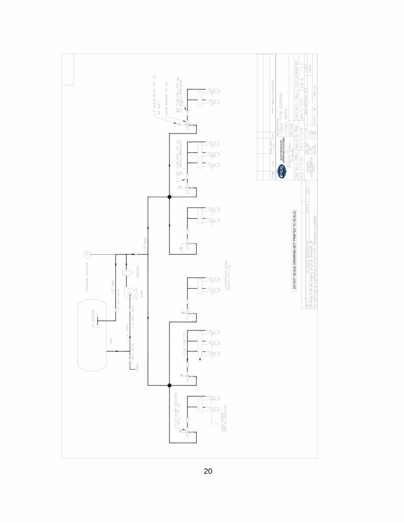
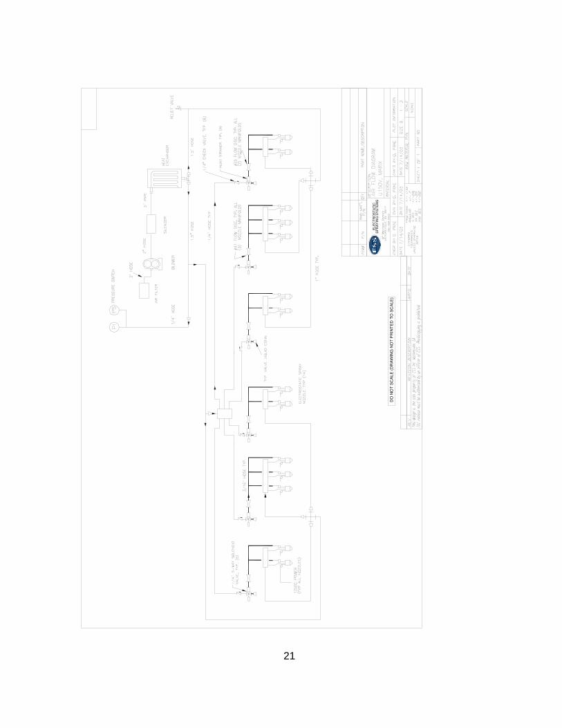
VIII. Trouble Shooting Guide 19 • Liquid Flow Diagram 20 • Air Flow Diagram 21
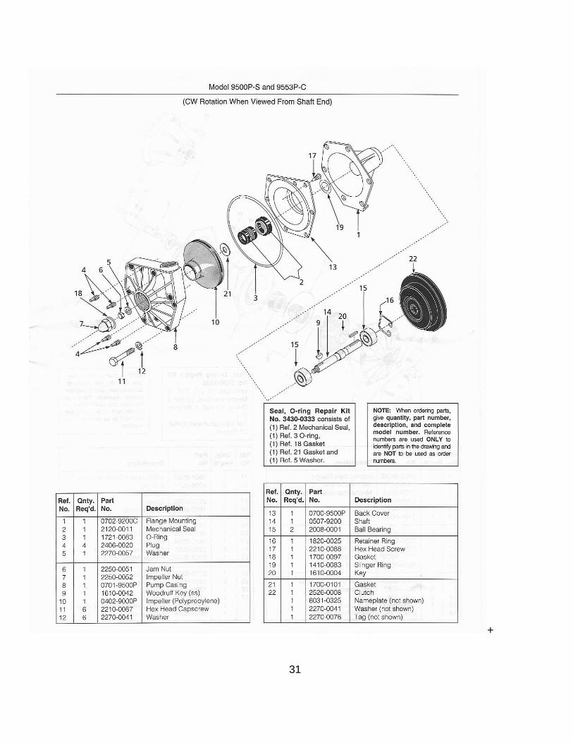
IX. Parts / Drawings 22 - 28 • Wiring Harnesses 29 • Control Panel 30 • Hypro Pump 31
2
3
I. Introduction
Congratulations! You have just purchased the most advanced spraying system on the market today. Electrostatic Spraying Systems, Inc. is committed to providing you with the most effective sprayer for delivery of today’s chemicals that is as easy to operate and maintain, as it is easy on the environment. Here at ESS, we work continuously to improve all of our products and their systems. To achieve this goal, we would like your comments. If you have any concerns, questions or suggestions, please contact us at the address or phone number below.
Electrostatic Spraying Systems, Inc.
62 Morrison Street Watkinsville, GA 30677
Phone: 800-213-0518 Fax: 706-769-8072
Email: [email protected]
Important! Please take the time to study this manual before operating the HT-150 Horizontal Trellis Grape Sprayertm. It contains important instructions on the safe setup and operation of this equipment. You will also find SAFETY PRECAUTIONS as well as helpful suggestions to maximize your productivity. Thank you! We appreciate your business and are proud that you have selected an ESS sprayer for your operation. *ESS HT-150 Horizontal Trellis Grape Sprayertm, HTtm, Maxchargetm, and the ESS logo are copyrights or registered trademarks of Electrostatic Spraying Systems, Inc.
Overview of the ESS model HT-150 Air-Assisted
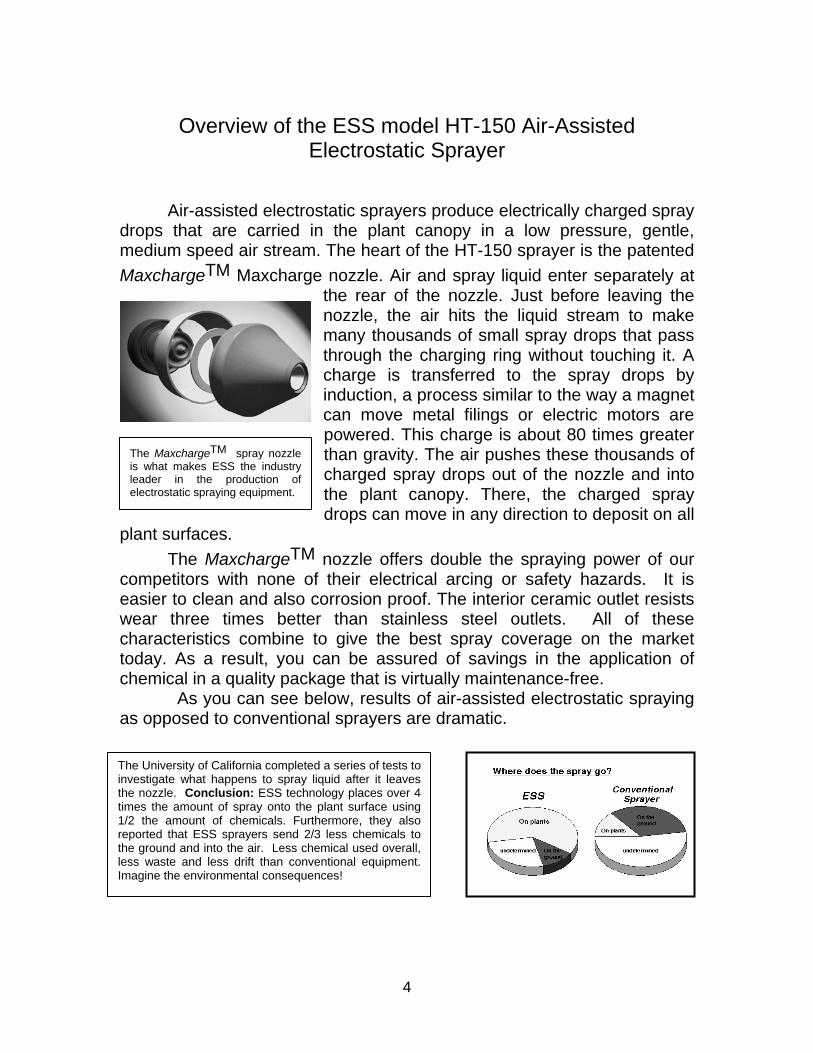
Electrostatic Sprayer Air-assisted electrostatic sprayers produce electrically charged spray drops that are carried in the plant canopy in a low pressure, gentle, medium speed air stream. The heart of the HT-150 sprayer is the patented MaxchargeTM Maxcharge nozzle. Air and spray liquid enter separately at
the rear of the nozzle. Just before leaving the nozzle, the air hits the liquid stream to make many thousands of small spray drops that pass through the charging ring without touching it. A charge is transferred to the spray drops by induction, a process similar to the way a magnet can move metal filings or electric motors are powered. This charge is about 80 times greater than gravity. The air pushes these thousands of charged spray drops out of the nozzle and into the plant canopy. There, the charged spray drops can move in any direction to deposit on all
plant surfaces.
The MaxchargeTM spray nozzle is what makes ESS the industry leader in the production of electrostatic spraying equipment.
The MaxchargeTM nozzle offers double the spraying power of our competitors with none of their electrical arcing or safety hazards. It is easier to clean and also corrosion proof. The interior ceramic outlet resists wear three times better than stainless steel outlets. All of these characteristics combine to give the best spray coverage on the market today. As a result, you can be assured of savings in the application of chemical in a quality package that is virtually maintenance-free. As you can see below, results of air-assisted electrostatic spraying as opposed to conventional sprayers are dramatic.
II. WARRANTY
The University of California completed a series of tests to investigate what happens to spray liquid after it leaves the nozzle. Conclusion: ESS technology places over 4 times the amount of spray onto the plant surface using 1/2 the amount of chemicals. Furthermore, they also reported that ESS sprayers send 2/3 less chemicals to the ground and into the air. Less chemical used overall, less waste and less drift than conventional equipment. Imagine the environmental consequences!
4
5
II. Warranty Electrostatic Spraying Systems, Inc. warrants to the original purchaser of this equipment that the equipment is free from any defects in material and workmanship for a period of one year after delivery. The attached warranty form must be returned within 30 days of delivery of the equipment for verification of delivery date and purchase or this warranty is void. Under this warranty, Electrostatic Spraying Systems, Inc. will repair or replace any defective items found within the one-year period. Electrostatic Spraying Systems, Inc. reserves its exclusive right to determine if the defective part is covered under this warranty and its choice of repairing or replacing the part. Parts must be returned for inspection in order to determine warranty.
DISCLAIMER OF IMPLIED WARRANTIES AND CONSEQUENTIAL DAMAGES
Electrostatic Spraying Systems, Inc. obligation under this warranty, to the extent allowed by law, is in lieu of all warranties, expressed or implied, including implied warranties of merchantability and fitness for a particular purpose and any liability for incidental or consequential damages with respect to the sale or use of the items warranted. Such incidental or consequential damages shall include but not be limited to: transportation charges, cost of installation, duty, taxes, charges for normal service or adjustments, loss of profits, use, income, crops, or production, or increased cost of operation, or spoilage or damage to material, or other commercial loss arising in connection with the sale, installation, use, repair or replacement of ESS products, or detention or delay in the delivery of equipment or parts.
THIS WARRANTY SHALL NOT APPLY:
1. To ESS vendor items that carry their own warranties such as, but not limited to, air compressors or blowers, liquid pumps, pop off valves or air switches, etc.
2. If, in the sole discretion of Electrostatic Spraying Systems, Inc., the unit has been subject to misapplication, abuse, misuse, negligence, fire or other accident.
3. From damage resulting from corrosive action of any gases, liquids, or powders handled by the equipment or improper installation of warrantable parts, or failure to properly follow maintenance procedures as outlined in this manual.
4. If the unit has been altered or repaired in a manner which, in the sole judgment of Electrostatic Spraying Systems, Inc., such alteration or repair affects the unit’s performance, stability, or reliability.
5. If parts not made, specified, or supplied by Electrostatic Spraying Systems, Inc. have been used in connection with or substituted on the unit, if in the sole judgment of Electrostatic Spraying Systems, Inc. such parts affect the unit’s performance, stability or reliability.
6. To normal maintenance and service or replacement items such as, but not limited to lubricants, filters, drive belts, or to normal deterioration of such things as exterior finish due to use and exposure in various climates. Furthermore, it shall be the responsibility of the purchaser to follow all operation checks listed in this manual to ensure that the unit is in good working order. NO EMPLOYEE OR REPRESENTATIVE OF ELECTROSTATIC SPRAYING
SYSTEMS, INC. IS AUTHORIZED TO CHANGE THIS WARRANTY IN ANY WAY OR GRANT ANY OTHER WARRANTY UNLESS SUCH CHANGE IS MADE IN WRITING AND SIGNED BY A CORPORATE OFFICER OF ELECTROSTATIC
SPRAYING SYSTEMS, INC.
Product Warranty Registration Form
Electrostatic Spraying Systems, Inc.
Model Number__HT-150_____________
Serial Number______________________
Purchase Date______________________
Owner’s Name____________________________________________________
Company Name___________________________________________________
Address__________________________________________________________
City____________________ State___________________ Zip______________
Phone Number__________________ Fax Number________________________
Email Address_____________________________________________________
Owner’s Signature X_______________________________________________ *Your signature indicates acceptance of equipment, a clear understanding of the warranty and receipt of instructions on safe and proper operating procedures. Instructions to validate your warranty:
1. Fill out this form. 2. Sign your name. 3. Make a copy for yourself. 4. Fax or mail this form to ESS, Inc.
Fax# 706-769-8072 Electrostatic Spraying Systems, Inc. 62 Morrison Street Watkinsville, GA 30677
5. If you have purchased several ESS products, please fill out a separate form for each one.
Instructions for a warranty claim:
1. Contact us first by fax/phone with a description of the problem. Include the product type, serial number, and your phone and fax numbers.
2. Return the defective part to ESS, Inc.
3. In the package with the returned part, please include the model and serial numbers and your written description of the problem.
4. If you need the part immediately, we recommend that you order it, and we will credit your account upon determination of coverage by warranty.
6
III. Safety Precautions
Chemical Precautions
OWNER’S/OPERATOR’S RESPONSIBILITY Study the owner’s manual. The owner is responsible for ensuring that all persons using this
equipment are properly trained to do so. It is the responsibility of the operator to become familiar with all safe and correct operating procedures of this product.
It is the owner’s responsibility to maintain this product in accordance with the guidelines described in the Owner’s Manual. Proper inspection of the equipment, repair or replacement of parts when continued use of the product would cause personal harm or damage or excessive wear to other parts is the responsibility of the owner.
Read and follow all instructions on the chemical or pesticide manufacturer’s label for the following: 1. Protective clothing, including, but not
limited to: • Eye protection • Rubber boots • Rubber gloves • Rubber apron • Hat • Cartridge respirator (when
handling, mixing and applying the chemical)
2. Handling: • Mixing • Storing • Disposing methods
3. Decontamination methods for chemical removal from persons, clothing and equipment.
4. Avoiding potential health and environmental hazards.
5. Medical treatment for poisoning symptoms.
6. Length of time before reentry into the sprayed area.
7. Proper posting or notification of sprayed areas.
Safety Precautions Lack of attention to safety can result in REDUCTION OF EFFICIENCY, ACCIDENT, PERSONAL INJURY OR DEATH. Watch for safety hazards and correct deficiencies promptly. Use the following safety precautions as a general guide when using this machine. Additional safety precautions are mentioned throughout this manual for specific operating and maintenance procedures. 1. Study and become familiar with the
owner’s manual. Failure to do so is considered a misuse of this equipment.
2. Before operating equipment, become familiar with all caution and warning decals affixed to the machine.
3. Do not allow children to operate the sprayer. Do not allow adults to operate the sprayer without proper instruction.
4. Keep the area of operation clear of all persons and animals.
5. Do not apply chemicals when weather conditions favor drift from treated areas.
6. Turn off the sprayer when leaving it unattended.
7
DECALS
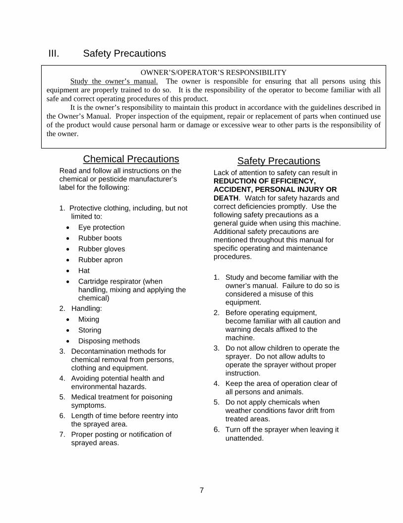
ESS places several decals on the HT-150 sprayer to remind the operators of safety and proper techniques. Always follow good, safe practice when operating this machinery. Note the locations on the equipment where these decals may be found. Replace them if they become worn or damaged and can no longer be read.
This warning is repeated several times in this manual. The decal is found on the front and rear of the spray tank.
IV. Initial Installation
The HT-150 sprayer is fully assembled and tested aAfter testing, the unit is partially disassembled for share several parts that must be reassembled before o
8
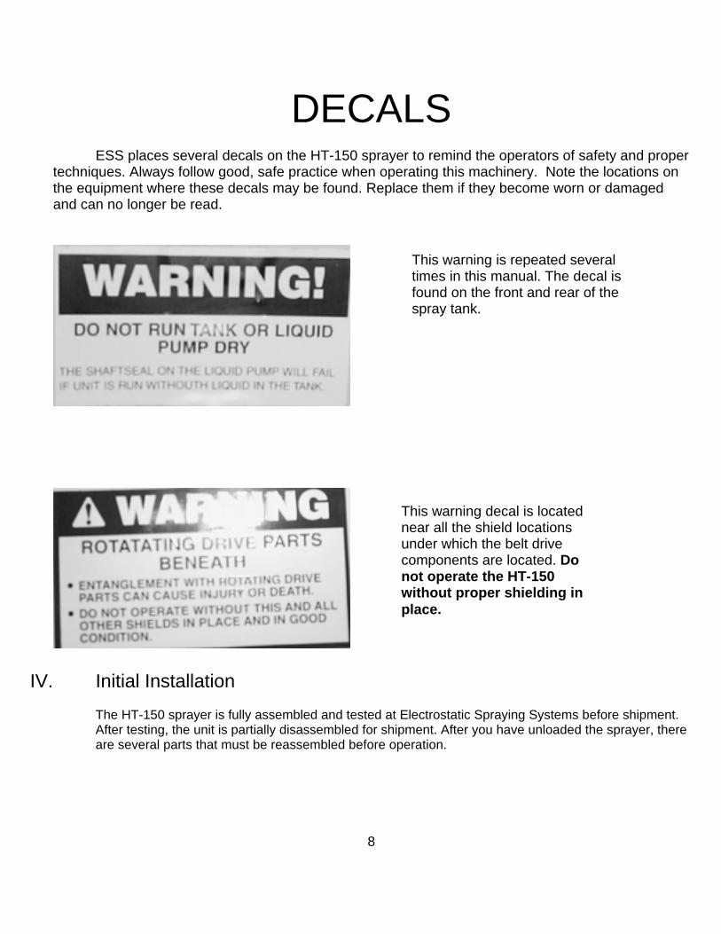
This warning decal is located near all the shield locations under which the belt drive components are located. Do not operate the HT-150 without proper shielding in place.
t Electrostatic Spraying Systems before shipment. ipment. After you have unloaded the sprayer, there peration.
• Installing the Driveline
Mount the sprayer on the tractor and cut the driveline to fit. Follow the directions from the Bondioli and Pavesi manual paying particular attention to the length guideline on page 6. Also, one end of the driveline shield tube is marked with a tractor symbol to indicate that end attaches to the tractor PTO.
• Installing the Control Box The control box mounts in the tractor cab at any location within easy reach of the operator. Some common positions are overhead or to the right. Attach the red wire directly to the tractor battery 12-volt terminal post and the green wire directly to the tractor ground post. Failure to ground the system properly can cause premature failure of the power supplies. Make sure that you are not operating on a 24-volt tractor system. Contact the ESS service representative for instructions in this case.
Attach the electrical cables to the front of the HT-150 sprayer.
V. Operating Instructions
Fill the main liquid tank with water. Make sure the liquid direction control located in front of the rinse tank is in the spray position. Operating the sprayer without water in the tank will cause damage to the centrifugal pump seals!
• Setting the Air Pressure With the tractor just above idle speed, engage the PTO and increase the tractor speed until the air
pressure reading is around 15 PSI. The blower is equipped with a pop off valve that protects the blower from overpressure. The noise created by the pop off valve will alert the operator to slow the tractor PTO speed until the pop off shuts. At this point, the blower will be operating at its maximum potential for correct spraying. Sometimes, there is minimal leaking of air from the pop off valve during operation. This is normal.
• Setting the Liquid Pressure Turn on the main power switch and verify that the hour meter is working. Now, turn on the main spray switch. Next turn on each of the solenoids that controls the individual nozzle groups. Each section will begin to spray.
At the front of the sprayer is a ¼ turn valve next to the liquid pressure gauge. Opening this valve will decrease pressure and closing the valve will increase pressure. This valve restricts the return flow of liquid to the tank. There is a hole in the valve so that when it is fully closed, some liquid always returns to the tank to maintain tank agitation. Also, this keeps the gauge from failing in an overpressure situation. Liquid pressure will be factory between 20 & 30 psi in order to achieve a nominal 180-ml/minute flow ± 10% out of each nozzle.
Use the graduated cylinder found in the parts kit to check all nozzle flows before spraying. Any flash or small piece of material that has broken loose after ESS’ own testing or in transportation can be cleaned at this time following the procedure outlined in the maintenance section. Average the readings over the entire sprayer to determine the nozzle flow rate to use when applying chemicals.
9

• Turning on Charging
When the power supply switch was turned on, the power supplies activate to charge the spray. There is a bank of LED lights on the control panel that will glow for each power supply operating on the spray bars.
Using the meter supplied by ESS, check the charge level of all nozzles. Follow the procedure in the maintenance section to correctly set the meter for measuring current. Readings will vary from 9 to 18 depending upon various conditions. Any reading of 0.00 indicates a nozzle that is not receiving voltage. Any low readings from 2 to 6 indicate that the nozzle has some flash present and needs to be clean. If all the nozzles read low, the sprayer is not grounded properly
• Shutting Down the Sprayer It is important to shut the sprayer down correctly so that the liquid lines will be purged of chemical. Turn off the main solenoid switch or the six independent liquid solenoid switches to shut off the solenoid valves so that air will purge the liquid lines in the boom. Wait a few seconds until the nozzles quit spraying. They may spit intermittently, but at this time, turn off the power supply switch, then the main power switch.
VI. Calibration and Field Operation The model HT-150 is a low volume sprayer. Tank mixes must be adjusted accordingly. The average
nozzle flow rate can be adjusted and operated from 100 to 200 ml/min. Outside this range, nozzle charging is poor and spray deposition is low. Optimum performance is achieved by setting the liquid flow in the nozzles around 180 ml/min. Adjust the liquid pressure with the throttle valve. Adjust the spray bars so that the nozzles are about 18 inches from the crop. At this distance, the nozzle air will push the charged spray into the plant canopy and provide adequate overlap of the spray cloud from each nozzle. If the boom is too close to the crop, then the air will push the spray into the crop before it has time to be attracted to the top leaf surfaces. This is known as striping. If the spray bars are too far away, then spray may not reach the into the canopies or spray drift will occur. In windy conditions, the nozzles can be angled forward and the spray bars moved closer to the crop. Take care to observe that there is overlap of the spray before it enters the plant canopy. Adjust accordingly.
When mixing chemicals for a low volume sprayer, it is good practice to conduct a jar test to determine if the chemicals to be mixed are compatible. If they are not, then investigate alternative chemicals or use a compatibility agent to maintain the chemicals in suspension. It is also a good idea to treat the water with a pH agent. ESS does not recommend the use of wetting agents or spreader-stickers.
10
11
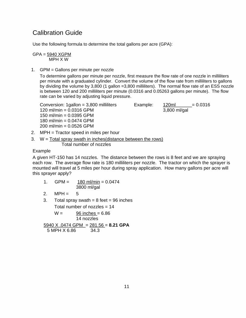
Calibration Guide Use the following formula to determine the total gallons per acre (GPA): GPA = 5940 XGPM MPH X W
1. GPM = Gallons per minute per nozzle To determine gallons per minute per nozzle, first measure the flow rate of one nozzle in milliliters per minute with a graduated cylinder. Convert the volume of the flow rate from milliliters to gallons by dividing the volume by 3,800 (1 gallon =3,800 milliliters). The normal flow rate of an ESS nozzle is between 120 and 200 milliliters per minute (0.0316 and 0.05263 gallons per minute). The flow rate can be varied by adjusting liquid pressure.
Conversion: 1gallon = 3,800 milliliters Example: 120ml = 0.0316 120 ml/min = 0.0316 GPM 3,800 ml/gal 150 ml/min = 0.0395 GPM 180 ml/min = 0.0474 GPM 200 ml/min = 0.0526 GPM
2. MPH = Tractor speed in miles per hour 3. W = Total spray swath in inches(distance between the rows)
Total number of nozzles Example A given HT-150 has 14 nozzles. The distance between the rows is 8 feet and we are spraying
each row. The average flow rate is 180 milliliters per nozzle. The tractor on which the sprayer is mounted will travel at 5 miles per hour during spray application. How many gallons per acre will this sprayer apply?
1. GPM = 180 ml/min = 0.0474 3800 ml/gal
2. MPH = 5 3. Total spray swath = 8 feet = 96 inches
Total number of nozzles = 14 W = 96 inches = 6.86 14 nozzles
5940 X .0474 GPM = 281.56 = 8.21 GPA 5 MPH X 6.86 34.3
VII. Cleaning and Maintenance
It is very important to follow all the maintenance and cleaning procedures to ensure that the electrostatic sprayer will function its best. While the Maxcharge nozzles outperform all electrostatic spray technology on the market today, occasional, regular cleaning will result in peak operating performance. The sprayer can be washed down prior to any individual component cleaning. Pressure washers will not damage the electrical components or the nozzles; however, use Silglyde electrical grease in all connections exposed to pressure washing.
• The Nozzle
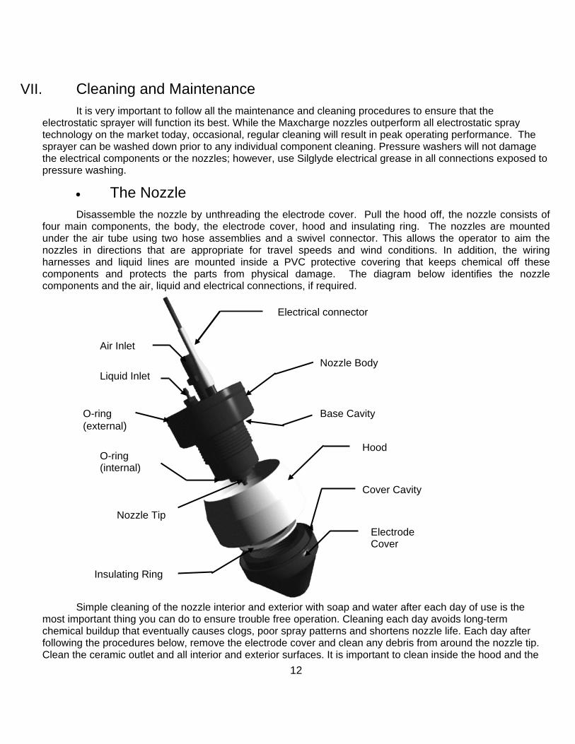
Disassemble the nozzle by unthreading the electrode cover. Pull the hood off, the nozzle consists of four main components, the body, the electrode cover, hood and insulating ring. The nozzles are mounted under the air tube using two hose assemblies and a swivel connector. This allows the operator to aim the nozzles in directions that are appropriate for travel speeds and wind conditions. In addition, the wiring harnesses and liquid lines are mounted inside a PVC protective covering that keeps chemical off these components and protects the parts from physical damage. The diagram below identifies the nozzle components and the air, liquid and electrical connections, if required.
Simp
most importchemical bufollowing thClean the c
Electrical connector
Air Inlet Nozzle Body
Liquid Inlet
le cleaning of the nozzle interior and exterior with soap a
ant thing you can do to ensure trouble free operation. Cleildup that eventually causes clogs, poor spray patterns an
e procedures below, remove the electrode cover and cleaeramic outlet and all interior and exterior surfaces. It is im
Base Cavity
O-ring (internal)
Insulating Ring
12
Hood
Cover CavityNozzle Tip
O-ring (external)
nd water after each day of use is the aning each day avoids long-term d shortens nozzle life. Each day after
n any debris from around the nozzle tip. portant to clean inside the hood and the
Electrode Cover

two cavities shown in the above diagram. Wipe clean the exterior of the wire and all hoses and fittings connected to the nozzle. Put Silglyde silicon grease inside the nozzle electrical connections whenever you have disconnected the nozzle.
Silglyde will keep all the electrical connections free from corrosion.
Apply enough Silglyde to coat the metal pin and socket connections of the nozzles and also the low voltage wire connectors.
After cleaning, make sure the internal and external o-rings are still in place. Put the insulating ring back on the nozzle and screw the electrode cover back. Replace the hood, pushing it up against the external o-ring. The electrode cover should be hand tight. Never use pliers or other tools to tighten it. The insulating ring should be loose.
• Flushing the Sprayer After spraying and proper disposal of any remaining spray solution, flush the HT-150 sprayer with a
mixture of water and a cleaning agent. ESS recommends the use of NUTRA-SOL cleaner which can be purchased from ESS.
Nutrasol cleaner is an excellent neutralizer of chemical deposits in your tank and liquid lines. Recommended use of this product will keep your equipment operating at peak performance. The recommended mixing ratio is 4 ounces in 12.5 gallons of water.
13
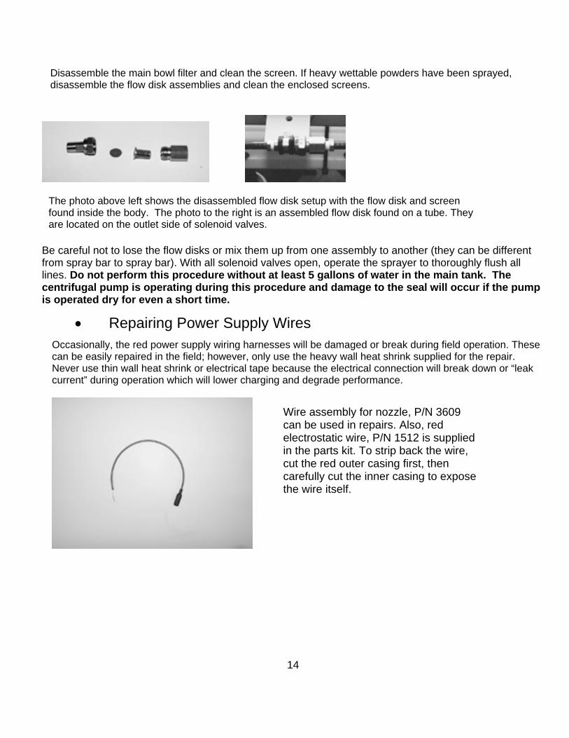
Disassemble the main bowl filter and clean the screen. If heavy wettable powders have been sprayed, disassemble the flow disk assemblies and clean the enclosed screens.
The photo above left shows the disassembled flow disk setup with the flow disk and screen found inside the body. The photo to the right is an assembled flow disk found on a tube. They are located on the outlet side of solenoid valves.
Be careful not to lose the flow disks or mix them up from one assembly to another (they can be different from spray bar to spray bar). With all solenoid valves open, operate the sprayer to thoroughly flush all lines. Do not perform this procedure without at least 5 gallons of water in the main tank. The centrifugal pump is operating during this procedure and damage to the seal will occur if the pump is operated dry for even a short time.
• Repairing Power Supply Wires Occasionally, the red power supply wiring harnesses will be damaged or break during field operation. These can be easily repaired in the field; however, only use the heavy wall heat shrink supplied for the repair. Never use thin wall heat shrink or electrical tape because the electrical connection will break down or “leak current” during operation which will lower charging and degrade performance.
Wire assembly for nozzle, P/N 3609 can be used in repairs. Also, red electrostatic wire, P/N 1512 is supplied in the parts kit. To strip back the wire, cut the red outer casing first, then carefully cut the inner casing to expose the wire itself.
14
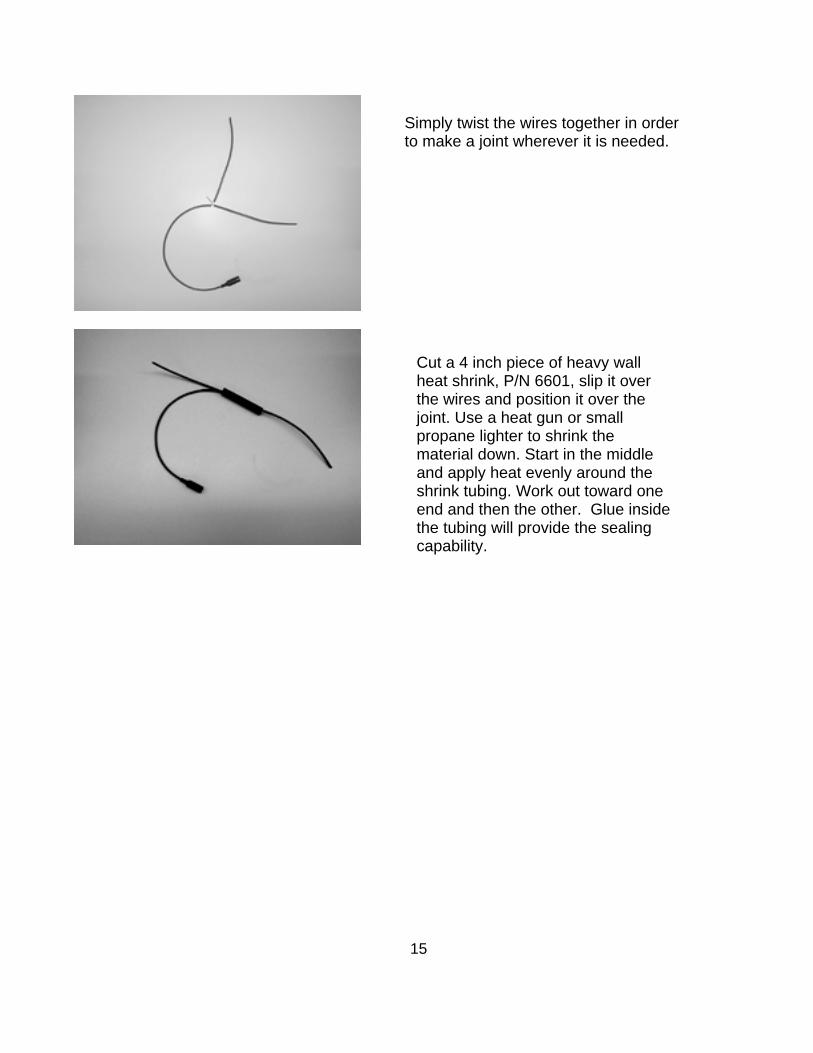
Simply twist the wires together in order to make a joint wherever it is needed.
Cut a 4 inch piece of heavy wall heat shrink, P/N 6601, slip it over the wires and position it over the joint. Use a heat gun or small propane lighter to shrink the material down. Start in the middle and apply heat evenly around the shrink tubing. Work out toward one end and then the other. Glue inside the tubing will provide the sealing capability.
15
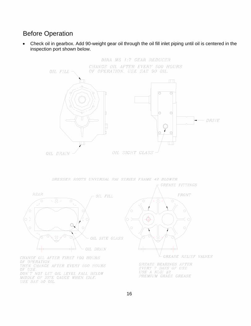
Before Operation • Check oil in gearbox. Add 90-weight gear oil through the oil fill inlet piping until oil is centered in the
inspection port shown below.
16
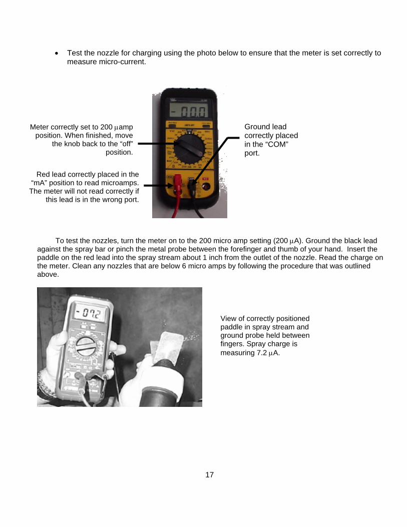
• Test the nozzle for charging using the photo below to ensure that the meter is set correctly to measure micro-current.
•
Red lead correctly placed in the “mA” position to read microamps.
The meter will not read correctly if this lead is in the wrong port.
Meter correctly set to 200 µamp position. When finished, move
the knob back to the “off” position.
Ground lead correctly placed in the “COM” port.
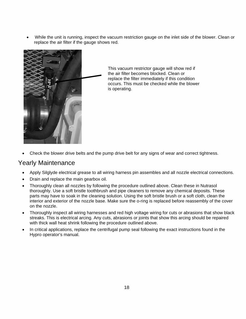
To test the nozzles, turn the meter on to the 200 micro amp setting (200 µA). Ground the black lead against the spray bar or pinch the metal probe between the forefinger and thumb of your hand. Insert the paddle on the red lead into the spray stream about 1 inch from the outlet of the nozzle. Read the charge on the meter. Clean any nozzles that are below 6 micro amps by following the procedure that was outlined above.
View of correctly positioned paddle in spray stream and ground probe held between fingers. Spray charge is measuring 7.2 µA.
17
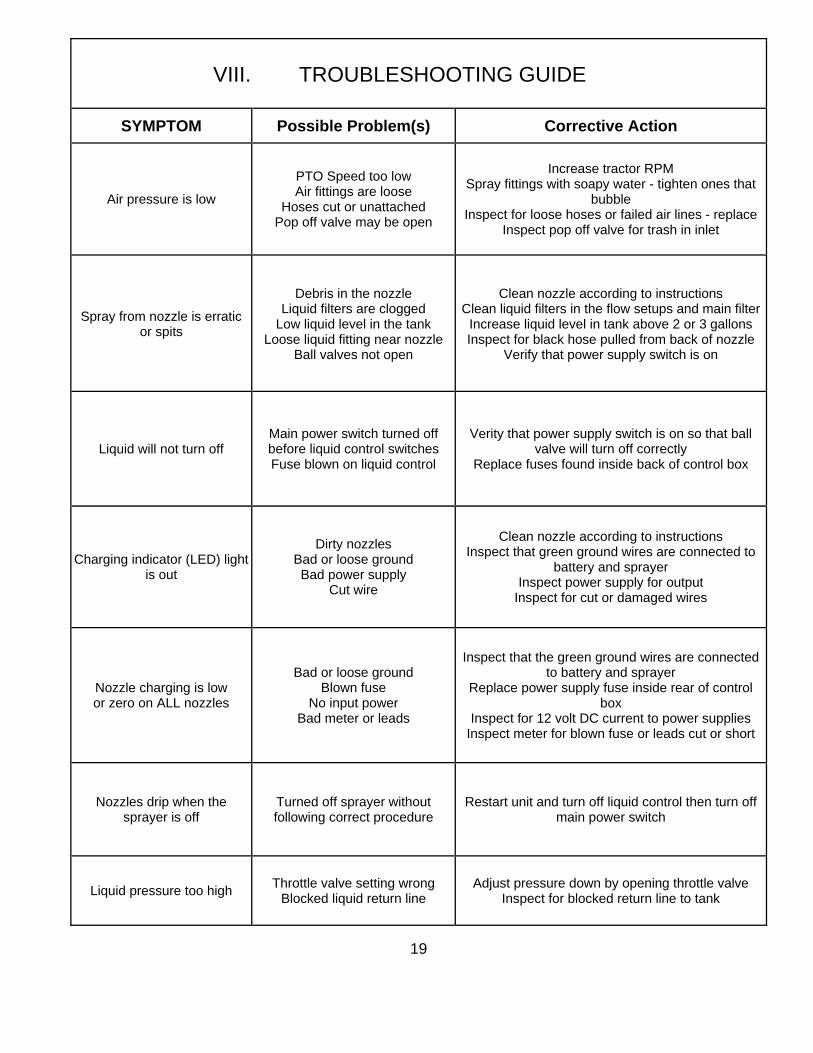
• While the unit is running, inspect the vacuum restriction gauge on the inlet side of the blower. Clean or
replace the air filter if the gauge shows red.
This vacuum restrictor gauge will show red if the air filter becomes blocked. Clean or replace the filter immediately if this condition occurs. This must be checked while the blower is operating.
• Check the blower drive belts and the pump drive belt for any signs of wear and correct tightness.
Yearly Maintenance • Apply Silglyde electrical grease to all wiring harness pin assembles and all nozzle electrical connections. • Drain and replace the main gearbox oil. • Thoroughly clean all nozzles by following the procedure outlined above. Clean these in Nutrasol
thoroughly. Use a soft bristle toothbrush and pipe cleaners to remove any chemical deposits. These parts may have to soak in the cleaning solution. Using the soft bristle brush or a soft cloth, clean the interior and exterior of the nozzle base. Make sure the o-ring is replaced before reassembly of the cover on the nozzle.
• Thoroughly inspect all wiring harnesses and red high voltage wiring for cuts or abrasions that show black streaks. This is electrical arcing. Any cuts, abrasions or joints that show this arcing should be repaired with thick wall heat shrink following the procedure outlined above.
• In critical applications, replace the centrifugal pump seal following the exact instructions found in the Hypro operator‘s manual.
18
19
VIII. TROUBLESHOOTING GUIDE
SYMPTOM Possible Problem(s) Corrective Action
Air pressure is low
PTO Speed too low Air fittings are loose
Hoses cut or unattached Pop off valve may be open
Increase tractor RPM Spray fittings with soapy water - tighten ones that
bubble Inspect for loose hoses or failed air lines - replace
Inspect pop off valve for trash in inlet
Spray from nozzle is erratic or spits
Debris in the nozzle Liquid filters are clogged
Low liquid level in the tank Loose liquid fitting near nozzle
Ball valves not open
Clean nozzle according to instructions Clean liquid filters in the flow setups and main filter
Increase liquid level in tank above 2 or 3 gallons Inspect for black hose pulled from back of nozzle
Verify that power supply switch is on
Liquid will not turn off Main power switch turned off before liquid control switches Fuse blown on liquid control
Verity that power supply switch is on so that ball valve will turn off correctly
Replace fuses found inside back of control box
Charging indicator (LED) light is out
Dirty nozzles Bad or loose ground Bad power supply
Cut wire
Clean nozzle according to instructions Inspect that green ground wires are connected to
battery and sprayer Inspect power supply for output
Inspect for cut or damaged wires
Nozzle charging is low or zero on ALL nozzles
Bad or loose ground Blown fuse
No input power Bad meter or leads
Inspect that the green ground wires are connected to battery and sprayer
Replace power supply fuse inside rear of control box
Inspect for 12 volt DC current to power supplies Inspect meter for blown fuse or leads cut or short
Nozzles drip when the sprayer is off
Turned off sprayer without following correct procedure
Restart unit and turn off liquid control then turn off main power switch
Liquid pressure too high Throttle valve setting wrong Blocked liquid return line
Adjust pressure down by opening throttle valve Inspect for blocked return line to tank
20
21
22
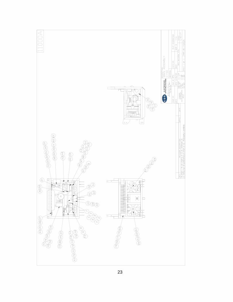
IX. Parts
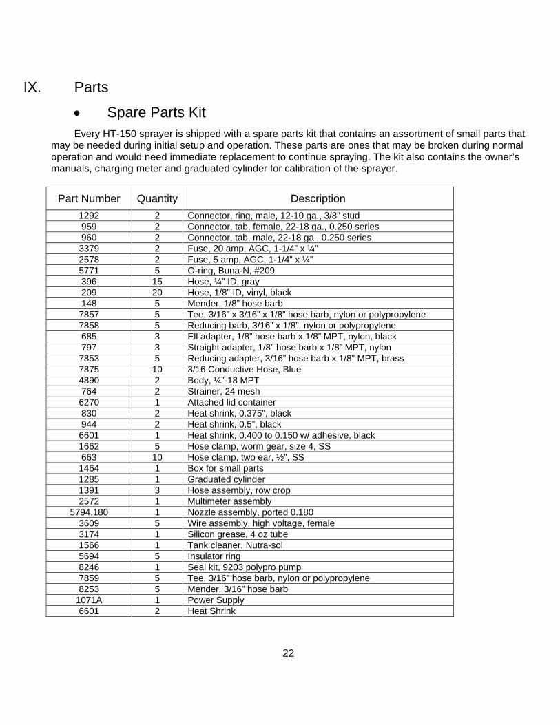
• Spare Parts Kit Every HT-150 sprayer is shipped with a spare parts kit that contains an assortment of small parts that
may be needed during initial setup and operation. These parts are ones that may be broken during normal operation and would need immediate replacement to continue spraying. The kit also contains the owner’s manuals, charging meter and graduated cylinder for calibration of the sprayer.
Part Number Quantity Description 1292 2 Connector, ring, male, 12-10 ga., 3/8” stud 959 2 Connector, tab, female, 22-18 ga., 0.250 series 960 2 Connector, tab, male, 22-18 ga., 0.250 series 3379 2 Fuse, 20 amp, AGC, 1-1/4” x ¼” 2578 2 Fuse, 5 amp, AGC, 1-1/4” x ¼” 5771 5 O-ring, Buna-N, #209 396 15 Hose, ¼” ID, gray 209 20 Hose, 1/8” ID, vinyl, black 148 5 Mender, 1/8” hose barb 7857 5 Tee, 3/16” x 3/16” x 1/8” hose barb, nylon or polypropylene 7858 5 Reducing barb, 3/16” x 1/8”, nylon or polypropylene 685 3 Ell adapter, 1/8” hose barb x 1/8” MPT, nylon, black 797 3 Straight adapter, 1/8” hose barb x 1/8” MPT, nylon 7853 5 Reducing adapter, 3/16” hose barb x 1/8” MPT, brass 7875 10 3/16 Conductive Hose, Blue 4890 2 Body, ¼”-18 MPT 764 2 Strainer, 24 mesh 6270 1 Attached lid container 830 2 Heat shrink, 0.375”, black 944 2 Heat shrink, 0.5”, black 6601 1 Heat shrink, 0.400 to 0.150 w/ adhesive, black 1662 5 Hose clamp, worm gear, size 4, SS 663 10 Hose clamp, two ear, ½”, SS 1464 1 Box for small parts 1285 1 Graduated cylinder 1391 3 Hose assembly, row crop 2572 1 Multimeter assembly
5794.180 1 Nozzle assembly, ported 0.180 3609 5 Wire assembly, high voltage, female 3174 1 Silicon grease, 4 oz tube 1566 1 Tank cleaner, Nutra-sol 5694 5 Insulator ring 8246 1 Seal kit, 9203 polypro pump 7859 5 Tee, 3/16” hose barb, nylon or polypropylene 8253 5 Mender, 3/16” hose barb
1071A 1 Power Supply 6601 2 Heat Shrink
23
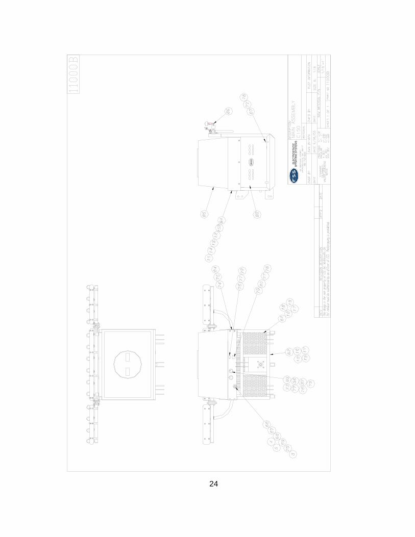
24
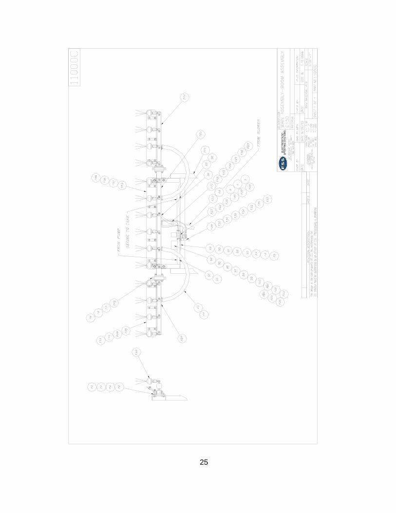
25

26
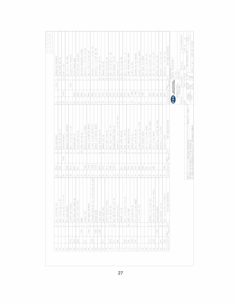
27

28

29
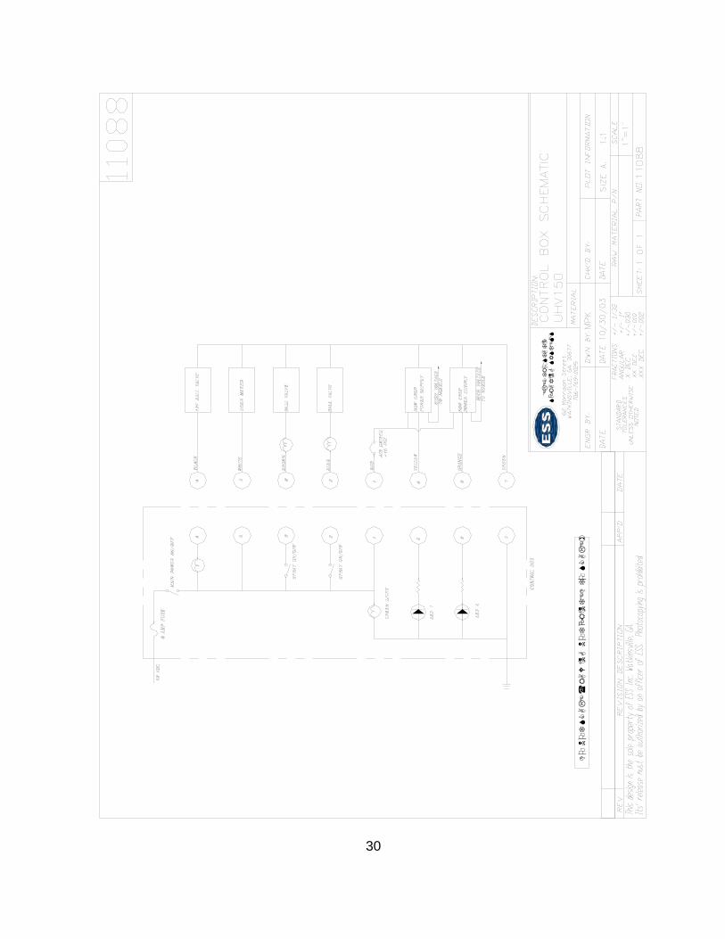
30
+
31