insulators - hubbell power systems - products for electric
TRANSCRIPT

A Better Design. A Better Insulator.
Catalog 24
®
Insulators®

LIMITED WARRANTY AND LIMITATION OF LIABILITY MATERIAL: HPS warrants all products sold by it to be merchantable (as such term is defined in the Uniform Commercial Code) and to be free from defects in material and workmanship. Buyer must notify HPS promptly of any claim under this warranty. The Buyer’s exclusive remedy for breach of this warranty shall be the repair or replacement, F.O.B. factory, at HPS’s option, of any product defective under the warranty, which is returned to HPS within one year from the date of shipment. NO OTHER WARRANTY, WHETHER EXPRESS OR ARISING BY OPERATION OF THE LAW, COURSE OF DEALING, USAGE OF TRADE OR OTHERWISE IMPLIED, SHALL EXIST IN CONNECTION WITH HPS’S PRODUCTS OR ANY SALE OR USE THEREOF. HPS SHALL IN NO EVENT BE LIABLE FOR ANY LOSS OF PROFITS OR CONSEQUENTIAL OR SPECIAL DAMAGES INCURRED BY BUYER. HPS’s warranty shall run only to the first Buyer of a product from HPS, from HPS’s Buyer, or from an original equipment manufacturer reselling HPS’s product, and is non-assignable and non-transferable and shall be of no force and effect if asserted by any person other than such first Buyer. This warranty applies only to the use of the product as intended by HPS and does not cover any modification, misapplication, or misuse of said product. APPLICATION: HPS does not warrant the accuracy of and results from product or system performance recommendations resulting from any engineering analysis or study. This applies re-gardless of whether a charge is made for the recommendation, or if it is provided free of charge. Responsibility for selection of the proper product of application rests solely with the purchaser. In the event of errors or inaccuracies determined to be caused by HPS, its liability will be limited to the reperformance of any such analysis or study.
PURCHASER INSPECTIONS: Tests, inspections and acceptance of all material must be made at the factory. Purchasers’ inspectors are welcome at the factories and are provided with the neces-sary facilities for carrying out their work. Name and phone number of who should be contacted for inspection should be given to HPS no later than two weeks prior to scheduled shipment date.LIMITATION OF LIABILITY: IN NO EVENT, WHETHER AS A RESULT OF BREACH OF CONTRACT OR WARRANTY OR ALLEGED NEGLIGENCE, SHALL HPS BE LIABLE FOR SPECIAL OR CONSEQUENTIAL DAMAGES INCLUDING, BUT NOT LIMITED TO, LOSS OF PROFITS OR REVENUE, LOSS OF USE OF THE EQUIPMENT OR ANY ASSOCIATED EQUIPMENT, LOSS OF CAPITAL, COST OF SUBSTITUTE EQUIPMENT, FACILITIES OR SERVICES, DOWNTIME COSTS, OR CLAIMS OF THIRD PARTIES OF THE BUYER FOR SUCH DAMAGES. Any claim by Buyer for breach of the foregoing warranty shall be deemed waived by Buyer unless submitted to HPS in writing within thirty (30) days from the date Buyer discovered, or by reasonable inspection should have discovered the alleged breach. Any cause of action for breach of the foregoing warranty shall be brought within one year after the cause of action has accrued.
1850 Richland Avenue East, Aiken, SC 29801http://www.hubbellpowersystems.com
E-mail: [email protected]©Copyright 2010
NOTE: Because Hubbell has a policy of continuous product improvement, we reserve the right to change design and specifications without notice.

A Better Design. A Better Insulator.


Polymer (RTV) Seal
Counterbore Compression Seal
Radial Compression Seal
Overlap Compression Seal
Our Exclusive Four-Point Seal
®


page 1
Quadri*Sil® Insulators — A Century in the Making
With nearly 100 years of Ohio Brass insulator experience and product innovation, it’s no surprise that the next generation of insulator reliability carries the trusted name of Ohio Brass.
Ohio Brass (Hubbell Power Systems) is proud to offer a transmission insulator that triumphs over today’s unpredictable environment. Appropriately named, the Quadri*Sil® insulator incorporates a revolutionary four-point seal that, quite simply. . . prohibits moisture intrusion.
In addition, the Quadri*Sil® insulator optimizes the Ohio Brass commitment to excellence and the advancement of processes and materials. With a proprietary silicone-rubber compound and end-seal design, this direct-bonded insulator offers assurance that moisture penetration does not occur.
Today’s environment is unpredictable. Your insulator can’t be.
January 2011
The Ohio Brass commitment is simple and complete: we provide our customers the finest, most advanced products and expert technical assistance, before and after purchase. Every day. Worldwide.

page 2 January 2011
page 3
QuADrI*SIl® GEnErAl InFOrmAtIOn PAGE 4
The Heart of Quadri*Sil® Insulators ....................................................................... 4
Key to the Catalog Numbers .....................................................................8 and 33
Technical Terms Reference Guide ....................................................................... 34
SuSPEnSIOn InSulAtOrS PAGE 11
Corona Performance ......................................................................................... 12
End Fitting Detail ............................................................................................... 13
Quadri*Sil® 25 kip / 120 kN SML Data ............................................................... 14
Quadri*Sil® 30 kip SML Data ............................................................................. 15
Quadri*Sil® 160 kN SML Data ............................................................................ 16
Quadri*Sil® 50 kip / 210 kN SML Data ............................................................... 17
lInE POSt InSulAtOrS PAGE 19
Mechanical Ratings and Corona Performance ..................................................... 20
Quadri*Sil® Horizontal Line Posts ....................................................................... 21
Quadri*Sil® Vertical Line Posts ........................................................................... 22
Quadri*Sil® Base Fittings ................................................................................... 24
Quadri*Sil® Line Fittings .................................................................................... 25
Clamps and Assemblies .................................................................................... 26
BrAcED POSt InSulAtOrS PAGE 29
Braced Line Post Assemblies ............................................................................. 30
Assembly Drawings ........................................................................................... 31
Dimensions and Strength Ratings ...................................................................... 32
January 2011

page 4
DesignSealing System — This four-point sealing system provides superior performance by preventing moisture penetration between the silicone rubber and end-fitting interface. The design is based on four redundant seals that provide unmatched protection to the fiberglass core rod. RTV (Room Temperature Vulcanate) is completely encapsulated within the interior of the end-fitting and is not utilized as an exterior seal as with other silicone designs.
corona Shielding ring (CSR) — The Quadri*Sil® end-fitting design provides superior electric field shielding of the silicone rubber adjacent to the end-fitting. The superior shielding protects the silicone rubber on applications where an external corona ring is not required. Direct Bond — The silicone rubber material is bonded directly to the fiberglass core rod during the molding process. The resulting bond between the silicone rubber and fiberglass rod is mechanically stronger than the tear strength of the silicone rubber.
crimp method — A circumferential crimp creates a more uniform stress distribution to ensure the mechanical integrity of the Quadri*Sil® insulator. Ohio Brass pioneered the crimping process in 1976 — today it has become the industry standard.
[ Revolutionary Four-Point Seal ]
January 2011

page 5
components and materialsPolymer Weathersheds — The polymer weathershed material utilized in the Quadri*Sil® insulator design is a proprietary silicone-rubber compound specifically designed by Ohio Brass engineers for high-voltage insulator applications. The polymer weathershed material starts with 100-percent base silicone rubber before additives and fillers are compounded with the base rubber. Hubbell Power Systems (HPS) controls the entire process from the proprietary formulation to the complete mixing process. The proprietary formulation incorporates the inherent hydrophobicity and UV performance of silicone rubber while providing superior tracking performance as demonstrated in dry-band arcing tests. For more information about our silicone rubber, please contact your HPS representative.
Fiberglass core rod — The Quadri*Sil® suspension insulator’s fiberglass core rod is produced with boron-free, corrosion-resistant E-glass and epoxy resin. Quadri*Sil® line post insulators are manufac-tured with electrical grade glass and epoxy resin.
End Fittings — Made of steel or ductile iron, the end-fittings are directly attached to the fiberglass core rod by a circumferential crimping process. This crimping process allows the end fittings to utilize the rod’s inherent tensile strength.
Grading rings — Also known as corona rings, grading rings are manufactured using high-grade aluminum alloy, making them strong, light, and corrosion-resistant. Grading (corona) rings can be packaged separately or inside the insulator crates with all mounting hardware included.
leakage DistanceQuadri*Sil® suspension insulators feature standard and high leakage distance weathershed profiles for maximum resistance to contamination and leakage currents in various environmental applications. The hydrophobic nature of our silicone rubber ensures superior performance in contaminated environments.
January 2011

High Pressure WashingQuadri*Sil® transmission insulators normally do not require washing or other routine maintenance. Washing may be required if the insulators are installed in an area of severe environmental contamination. In the event that washing is required, the procedures outlined in Section IX of the “IEEE GUIDE FOR INSULATOR CLEANING,” IEEE STD 957-2005 are generally applicable.
mechanical ratingsQuadri*Sil® suspension insulators are rated and tested in accordance with IEC 61109 and ANSI C29.12. Quadri*Sil® line post insulators are rated and tested in accordance with IEC 61952 and ANSI C29.17. Certified test reports are available.
For suspension insulators, SML ratings are 120 kN, 160 kN, 210 kN, 25 kip, 30 kip, and 50 kip with appropriate rod size and end fittings. RTL ratings are consistent with the IEC and ANSI standards. Factory routine tests are conducted on 100 percent of all insulators to the RTL rating.
markings Markings for Quadri*Sil® suspension insulators are placed on a UV-resistant label located on the ground end fitting. Markings for Quadri*Sil® line post insulators are placed on a metal plate on the mounting base of the insulator. Markings include SML and RTL (for suspension), SCL and RCL (for line post), part number, assembly date code, and Hubbell Power Systems identification.
These markings are consistent with applicable IEC and ANSI standards.
Insulator lengthsQuadri*Sil® suspension insulators are available in lengths appropriate for 69 kV through 765 kV. Longer lengths can be produced for special projects. Intermediate lengths – those that fall in between the catalog numbers listed in the tables – are also available. Length increments are approximately 2.2 inches (56 mm) for suspension insulators and 2.4 inches (61 mm) for vertical and horizontal line post insulators.
page 6 January 2011
page 7
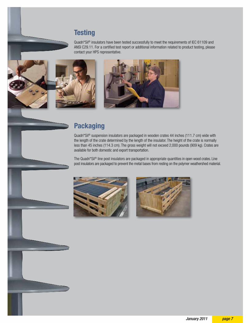
testingQuadri*Sil® insulators have been tested successfully to meet the requirements of IEC 61109 and ANSI C29.11. For a certified test report or additional information related to product testing, please contact your HPS representative.
PackagingQuadri*Sil® suspension insulators are packaged in wooden crates 44 inches (111.7 cm) wide with the length of the crate determined by the length of the insulator. The height of the crate is normally less than 45 inches (114.3 cm). The gross weight will not exceed 2,000 pounds (909 kg). Crates are available for both domestic and export transportation.
The Quadri*Sil® line post insulators are packaged in appropriate quantities in open wood crates. Line post insulators are packaged to prevent the metal bases from resting on the polymer weathershed material.
January 2011

page 8
cAtAlOG numBEr KEy
a
b
c
d
e
Insulator Type
Mechanical Strength
Suspension (SML), Rod Diameter 025 — 25 kip, 5/8” (16 mm) 030 — 30 kip, 5/8” (16 mm) 050 — 50 kip, 7/8” (22 mm) 120 — 120 kN, 5/8” (16 mm) 160 — 160 kN, 7/8” (22 mm) 210 — 210 kN, 7/8” (22 mm)
Polymer Length
3 digits for distance between metal parts, in inches
Top Fitting
Weathershed Profile
Post 250 — Series 250, standard strength 2.5”, (63.5 mm)
SuspensionS — Standard Leakage Distance (2.5)H — High Leakage Distance (2.9 or 3.3)
Line Post Insulators
0 — Tear Drop Blade
1 — Horizontal Clamptop
2 — Vertical Clamptop
3 — 5” (127 mm) Bolt Circle 5/8” (16 mm) Tapped Hole
5 — 5” (127 mm) Bolt Circle 5/8” (16 mm) Through Hole
9 — Long Tear Drop Blade
PostS — Standard Leakage Distance
P — Post or
S — Suspension
0 — Chain Eye
1 — ANSI Ball
2 — Y-Clevis
3 — ANSI Socket
4 — ANSI Straight Clevis
7 — IEC Ball Fitting 16 mm for 120 kN
20 mm for 160 kN and 210 kN
8 — IEC Straight Clevis
A — IEC Socket 16 mm for 120 kN
20 mm for 160 kN and 210 kN
The Quadri*Sil Insulators Numbering Scheme is organized according to a smart numbering system. Each group of digits defines a characteristic of the product you are ordering. To fill out this form, start on “a: Insulator Type.” Then, fill in your selection in the box corresponding to the letter “a.” Apply the same rule for all the other sections.
a)
Insulator type. Defines your insulator type: Post or Suspension.
Select “P” or “S” for Post or Suspension, respectively, and fill in your selection in the box designated for “a.” In this example, we selected a suspension insulator.
b)
Strength. Defines the mechanical strength of your insulator. Fill in your selection in the boxes designated for “b.”
Note: kip = Kilopound, kN = Kilonewton
For example, if you want a Suspension insulator with 25 kip, this is what
your form would look like so far:
c) Polymer length. Defines the polymer length of the insulator (please use
catalog tables for possible polymer lengths). Fill in your selection in the boxes designated for section “c.” For example, if you want a 49-inch polymer length,
enter:
d)
Weathershed Profile. Defines the leakage distance design. For a suspension
insulator with standard leakage distance, use “S.”
For a suspension insulator with high leakage distance, use “H.”
For a line post, only the standard leakage distance design is available. Fill in your selection in the box designated for “d.”
For example, if you want an insulator with high leakage distance, you would place an “H” in the box designated “d.”
e)
top Fitting. Defines the top end fitting of your insulator. Fill in your selection in the box designated for “e.” For example, if you want a suspension insulator with a Y-clevis top end fitting, you would place a “2” in the box designated for “e.”
0 4 9 HS 0 2 5
0 4 9 H 2S 0 2 5
0 4 9S 0 2 5
S 0 2 5
S
Suspension InsulatorsSuspension Insulators Line Post Insulators
January 2011
®

page 9
your complete part number will be S025049H201A
January 2011
f
g
00 - Chain Eye 02 - Aluminum Gain 12” (305 mm) CL1 mounting
03 - Aluminum Flat 8”x 10” (203 mm x 254 mm), 15/16” (24 mm) hole diameter
01 - ANSI Ball 04 - Aluminum Flat 8”x 13” (203 mm x 330 mm), 15/16” (24 mm) hole diameter
02 - Y-Clevis 05 - 5” (127 mm) Bolt Circle, 5/8” (16 mm) tapped hole
03 - ANSI Socket 07 - Steel Gain 12” (305 mm) CL mounting, 15/16” (24 mm) hole diameter
04 - ANSI Straight Clevis 08 - Steel Flat 8”x 13” (203 mm x 330 mm) MS2, 15/16” (24 mm) hole diameter
15 - 5” (127 mm) Bolt Circle, 5/8” (16 mm) through hole07 - IEC Ball Fitting 16 mm for 120 kN or 20 mm for 160 kN and 210 kN08 - IEC Straight Clevis
0A - IEC Socket 16 mm for 120 kN or 20 mm for 160 kN and 210 kN
0 — No ring requiredA — >220 kV, 8” (203 mm) ring for suspension, 12” (305 mm) ring for series 250 postB — >330 kV series 250 postC — >400 kV, 12” (305 mm) line end and 8” (203 mm) ground end ring for suspensionD — >500 kV, 15” (381 mm) line end and 8” (203 mm) ground end ring for suspensionE — >735 kV, 15” (381 mm) line end and 12” (305 mm) ground end ring for suspension
Bottom Fitting
Rings
Examples:
Suspension Insulators Line Post Insulators
1 Center Line2 Horizontal x Vertical Mounting Pattern Spacing
f)
Bottom Fitting. Defines the bottom end fitting of your insulator. Fill in your selection in the boxes designated for “f.”
For example, if you want an ANSI ball bottom end fitting, you would place “01” in the boxes designated for “f.”
0 4 9 H 2S 0 2 5 0 1
0 4 9 H 2S 0 2 5 0 1 A
g)
rings. Defines your need for a Corona Ring. Fill in your selection in the box designated for “g.”
The example below shows a selection of a corona ring for 220 kV, 8” (203 mm) for
a suspension insulator.
Thus, “A” was placed in the box designated for “g.”
your final catalog numbershould look like thisFill out boxes according to instructions
Suspension Insulator, 25 kip, 49” of
Polymer Length, Standard Leakage Distance Profile (2.5), Top Fitting: Y-Clevis, Bottom Fitting: ANSI Ball, No Corona RingS025049S2010
Vertical Gain - See page 23 Table B
, 12” (305 mm) ring for suspension, 15” (381 mm) ring for
P250021S0020
Line Post Insulator, 2.5” (63.5 mm) Rod Diameter, 21.9” Polymer Length, Standard Leakage Distance, Top Fitting: Tear Drop Blade, Bottom Fitting: 2-Piece Aluminum Gain Base, No Corona Ring
page 10 January 2011

page 11
Suspension Insulators
tABlE OF cOntEntS PAGECorona Performance ........................................................................................ 12
End Fitting Detail .............................................................................................. 13
Quadri*Sil® 25 kip / 120 kN SML Data .............................................................. 14
Quadri*Sil® 30 kip SML Data ............................................................................ 15
Quadri*Sil® 160 kN SML Data ........................................................................... 16
Quadri*Sil® 50 kip / 210 kN SML Data .............................................................. 17
January 2011
®

page 12
recommended corona ring Installation tablenormal Applications: top Grounded, Bottom Energized
corona Performance
Quadri*Sil® insulators are RIV and corona free through 161 kV. The use of an external corona shielding ring is required at 220 / 230 kV and above. The table below details the rings necessary for 220 / 230 kV and above.
Part Number 271761 Part Number 271705 Part Number 271751
Quadri*Sil Suspen-sion Insulator
4.10”(104 mm)
15.00”(381 mm)
Quadri*Sil Suspen-sion Insulator
3.44”(87 mm)
12.0”(305 mm)
Quadri*Sil Suspen-sion Insulator
2.44”(62 mm)
8.0”(203 mm)
Electrical/Dimensional changes to the Suspension Insulatorwith External corona ring
Recommended Corona Rings by Line Voltage
LineVoltage
(kV)
Corona Ring Part Numbers
Ground EndGround End Ground EndLine EndLine End Line End
220/230 kV
330/345 kV
400 kV
500 kV
None
None
8" (203 mm)
8" (203 mm)
8" (203 mm)
12" (305 mm)
12" (305 mm)
15" (381 mm)
-
-
2717613001
2717613001
-
-
2717613002
2717613002
2717613002
2717053002
2717053002
2717513002
2717613001
2717053001
2717053001
2717513001
25 kip, 30 kip, 120 kN, 133 kN 50 kip, 160 kN, 210 kN
Physical and Electrical Characteristics
Dry Arc Distance inches (mm)Leakage Distance inches (mm)ANSI 60 Hz Flashover Dry — kV ANSI 60 Hz Flashover Wet — kVANSI Critical Flashover Positive — kVANSI Critical Flashover Negative — kVIEC Wet Switching Impulse Withstand — kVIEC Power Frequency Wet Withstand — kVIEC Lightning Impulse Withstand Positive — kVIEC Lightning Impulse Withstand Negative — kVNet Weight pounds (kg)
220/230 kVRing
-0.63 (-16)0
-10-10-10-10N/A-10-10-10
2.1 (1.0)
330/345 kVRing
-1.32 (33.5)0
-20-10-20-20N/A-10-20-20
2.9 (1.3)
400 kVRing
-1.95 (49.5)0
-20-20-30-30N/A-20-30-30
5.0 (2.3)
500 kVRing
-2.67 (67.8)0
-30-30-40-50N/A-30-40-50
6.5 (2.9)
January 2011

page 13
chain Eye
mOSt cOmmOn EnD FIttInGS
y-clevis
Straight clevis Ball/Socket
SML
25 kip
(111 kN)
120 kN
30 kip
(133 kN)
36 kip
(160 kN)
210 kN
50 kip
(222 kN)
A0.62
(15.74)
0.62
(15.74)
0.75
(19.05)
0.75
(19.05)
0.75
(19.05)
0.75
(19.05)
C2.00
(50.8)
2.00
(50.8)
2.00
(50.8)
2.00
(50.8)
2.00
(50.8)
2.00
(50.8)
D0.62
(15.74)
0.62
(15.74)
0.85
(21.59)
0.85
(21.59)
0.85
(21.59)
0.85
(21.59)
Dimensions in. (mm)B
1.00
(25.4)
1.00
(25.4)
1.00
(25.4)
1.00
(25.4)
1.00
(25.4)
1.00
(25.4)
SML
25 kip
(111 kN)
120 kN
30 kip
(133 kN)
36 kip
(160 kN)
210 kN
50 kip
(222 kN)
B1.53
(38.86)
1.53
(38.86)
1.59
(40.39)
1.59
(40.39)
1.59
(40.39)
1.59
(40.39)
A0.75
(19.05)
0.75
(19.05)
0.88
(22.35)
0.88
(22.35)
0.88
(22.35)
0.88
(22.35)
Bolt Dia.0.75
(19)
0.75
(19)
0.88
(22)
0.88
(22)
0.88
(22)
0.88
(22)
Dimensions in. (mm)
SML
25 kip
(111 kN)
120 kN
30 kip
(133 kN)
36 kip
(160 kN)
210 kN
50 kip
(222 kN)
A1.41
(36)
1.41
(36)
1.41
(36)
1.81
(46)
1.81
(46)
Class
ANSI 52-6
IEC 16C
ANSI 52-6
IEC 19L
IEC 19L
N/A
B0.75
(19)
0.75
(19)
0.75
(19)
0.83
(21)
0.83
(21)
PD0.62
(16)
0.62
(16)
0.62
(16)
0.75
(19)
0.75
(19)
Dimensions in. (mm)SML
25 kip
(111 kN)
120 kN
30 kip
(133 kN)
36 kip
(160 kN)
210 kN
50 kip
(222 kN)
Class
ANSI 52-5
IEC 16 mm
ANSI 52-5
ANSI 52-8
(IEC 20 mm)
IEC 20 mm
ANSI 52-11
AB
C
øD
A
B
45º
A
B
PD
A B
A
January 2011

page 14
Suspension Insulators mechanical ratings Sml = 25 kip/120 kn rtl = 12.5 kip/60 kn rod Diameter: 5/8" (16 mm)
To determine the section length for an insulator with a different end fitting combination, please add or subtract the displayed length change in the table above. For configurations not shown, use the Catalog Number Key or contact your HPS representative.
Section Length Adjustment Table, Base End Fittings: Y-clevis-Ball (201)
Top Fitting
Y-ClevisEyeEyeANSI 52-5 SocketIEC 16 mm SocketANSI 52-6 ClevisANSI 52-6 Clevis
EyeANSI 52-5 BallEyeANSI 52-5 BallIEC 16 mm BallEyeANSI 52-5 Ball
200001000301A07400401
1.62 (41) 0.02 (0) 1.64 (42) -1.15 (-29) -0.03 (-1) 0.82 (21) -0.8 (-20)
Bottom Fitting Top and Bottom End Fitting Digits (“e” & “f”) in Catalog Number
Length Changeinches (mm)
Notes:n Dimensional and electrical values displayed in main table are for an insulator with Y-clevis and Ball end fittings.
n For voltages above 400 kV, other section lengths, or end fitting combinations, please contact your HPS representative.
n Electrical values are without corona ring. For voltages equal to or greater than 220 kV, refer to page 12 for corona rings and associated physical/electrical changes to the above data. Dimensions are within allowable tolerances as specified by IEC 61109 and
ANSI C29.12.
Selection Guide: Typical Line Voltage, kV
Catalog NumbersANSI / IEC
SectionLengthinches(mm)
NominalPolymerLengthinches
StrikeDistanceinches(mm)
LeakageDistanceinches(mm)
ANSI Values IEC Values
60-HzDry
Flashover(kV)
60-HzWet
Flashover(kV)
Critical ImpulsePositive
(kV)
Critical ImpulseNegative
(kV)
60-Hz1-minute
WetWithstand
(kV)
ImpulsePositive
Withstand(kV)
Impulse NegativeWithstand
(kV)
S025021S2010 / S120021S2010S025021H2010 / S120021H2010S025023S2010 / S120023S2010S025023H2010 / S120023H2010S025030S2010 / S120030S2010S025030H2010 / S120030H2010S025036S2010 / S120036S2010S025036H2010 / S120036H2010S025043S2010 / S120043S2010S025043H2010 / S120043H2010S025047S2010 / S120047S2010S025047H2010 / S120047H2010S025051S2010 / S120051S2010S025051H2010 / S120051H2010S025056S2010 / S120056S2010S025056H2010 / S120056H2010S025060S2010 / S120060S2010S025060H2010 / S120060H2010S025064S2010 / S120064S2010S025064H2010 / S120064H2010S025069S2010 / S120069S2010S025069H2010 / S120069H2010S025073S2010 / S120073S2010S025073H2010 / S120073H2010S025077S2010 / S120077S2010S025077H2010 / S120077H2010S025081S2010 / S120081S2010S025081H2010 / S120081H2010S025086S2010 / S120086S2010S025086H2010 / S120086H2010S025090S2010 / S120090S2010S025090H2010 / S120090H2010S025094S2010 / S120094S2010S025094H2010 / S120094H2010S025099S2010 / S120099S2010S025099H2010 / S120099H2010S025103S2010 / S120103S2010S025103H2010 / S120103H2010S025107S2010 / S120107S2010S025107H2010 / S120107H2010S025112S2010 / S120112S2010S025112H2010 / S120112H2010S025116S2010 / S120116S2010S025116H2010 / S120116H2010S025120S2010 / S120120S2010S025120H2010 / S120120H2010S025125S2010 / S120125S2010S025125H2010 / S120125H2010S025129S2010 / S120129S2010S025129H2010 / S120129H2010S025133S2010 / S120133S2010S025133H2010 / S120133H2010S025138S2010 / S120138S2010S025138H2010 / S120138H2010S025142S2010 / S120142S2010S025142H2010 / S120142H2010
33.3 (846)33.3 (846)35.4 (899)35.4 (899)
41.9 (1064)41.9 (1064)48.4 (1229)48.4 (1229)54.9 (1394)54.9 (1394)59.2 (1504)59.2 (1504)63.5 (1613)63.5 (1613)67.8 (1722)67.8 (1722)72.1 (1831)72.1 (1831)76.5 (1943)76.5 (1943)80.8 (2052)80.8 (2052)85.1 (2162)85.1 (2162)89.4 (2271)89.4 (2271)93.7 (2380)93.7 (2380)98.1 (2492)98.1 (2492)
102.4 (2601)102.4 (2601)106.7 (2710)106.7 (2710)
111 (2819)111 (2819)
115.3 (2929)115.3 (2929)119.7 (3040)119.7 (3040)
124 (3150)124 (3150)
128.3 (3259)128.3 (3259)132.6 (3368)132.6 (3368)136.9 (3477)136.9 (3477)141.3 (3589)141.3 (3589)145.6 (3698)145.6 (3698)149.9 (3807)149.9 (3807)154.2 (3917)154.2 (3917)
021021023023030030036036043043047047051051056056060060064064069069073073077077081081086086090090094094099099103103107107112112116116120120125125129129133133138138142142
21.5 (546)22 (559)
23.7 (602)24.1 (612)30.2 (767)30.6 (777)36.6 (930)37.1 (942)
43.1 (1095)43.6 (1107)47.4 (1204)47.9 (1217)51.8 (1316)52.2 (1326)56.1 (1425)56.5 (1435)60.4 (1534)60.9 (1547)64.7 (1643)65.2 (1656)
69 (1753)69.5 (1765)73.4 (1864)73.8 (1875)77.7 (1974)78.1 (1984)
82 (2083)82.5 (2096)86.3 (2192)86.8 (2205)90.6 (2301)91.1 (2314)
95 (2413)95.4 (2423)99.3 (2522)99.7 (2532)
103.6 (2631)104.1 (2644)107.9 (2741)108.4 (2753)112.2 (2850)112.7 (2863)116.6 (2962)
117 (2972)120.9 (3071)121.3 (3081)125.2 (3180)125.7 (3193)129.5 (3289)
130 (3302)133.8 (3399)134.3 (3411)138.2 (3510)138.6 (3520)142.5 (3620)142.9 (3630)
55 (1397)64 (1626)60 (1524)71 (1803)77 (1956)90 (2286)93 (2362)
110 (2794)110 (2794)129 (3277)121 (3073)142 (3607)132 (3353)155 (3937)143 (3632)168 (4267)154 (3912)181 (4597)165 (4191)194 (4928)176 (4470)207 (5258)187 (4750)220 (5588)198 (5029)233 (5918)209 (5309)246 (6248)220 (5588)259 (6579)231 (5867)272 (6909)242 (6147)285 (7239)253 (6426)298 (7569)264 (6706)310 (7874)275 (6985)323 (8204)286 (7264)336 (8534)297 (7544)349 (8865)308 (7823)362 (9195)319 (8103)375 (9525)330 (8382)388 (9855)341 (8661)
401 (10185)352 (8941)
414 (10516)363 (9220)
427 (10846)
220220250250315320385390460465500510540540585585625625660665695700735740780780815820860860890895925930960965990995
101010151040104510701075110011051125113011551160118011851205121012301235
210210235235305305365370435440475475510510545550580585615615650650685690720720745750780795815820850855875880890895920920945950975980
100010051030103510551060108010851105111011301135
370370415415525535635645730740800805865875935940
1000101010651070113011351200120512601270132513301400141014601470152015401575158516401645169016951750175518151820187518801935194019901995205020552110211521652170
350350395395510515620620725730795800865870935940
1005101010751075114011451210121512751280134513451420142014851495154515601600161016701670172517301790179518501855191519201975198020402045210021052160216522202225
145150165165210210255260300305330330360360385390410415435440465465490495515515540540560565585585610615630635655660675675695700720720735740760760780780795800815820835835
315325350355445450540540630635690695750 760810 815870880930940990 995
10501055110511151165117012201225127512851335 134013951395144514501500151015551565161516201665 16701720172517701780182518301880188519301935
300305330335430435525535625630685690750 755810 815875880940945995
100510601065112011251180118512401245130013051355 136514151425147514851530153515901595164516551705 17101755176518151820187018751925193019801980
69 110 132 161 220 330 400
Section Length
Section Length
High Leak Design
Standard Design
January 2011

page 15
Suspension Insulators mechanical ratings Sml = 30 kip rtl = 15 kip rod Diameter: 5/8" (16 mm)
Section Length Adjustment Table, Base End Fittings: Y-clevis-Ball (201)
Y-ClevisEyeEyeANSI 52-5 SocketIEC 16 mm SocketANSI 52-6 ClevisANSI 52-6 Clevis
EyeANSI 52-5 BallEyeANSI 52-5 BallIEC 16 mm BallEyeANSI 52-5 Ball
200001000301A07400401
1.62 (41) 0.02 (0) 1.64 (42) -1.15 (-29) -0.03 (-1) 0.82 (21) -0.8 (-20)
Top and Bottom End Fitting Digits (“e” & “f”) in Catalog Number
Length Changeinches (mm)
To determine the section length for an insulator with a different end fitting combination, please add or subtract the displayed length change in the table above. For configurations not shown, use the Catalog Number Key or contact your HPS representative.
Selection Guide: Typical Line Voltage, kV
CatalogNumbers
ANSI
SectionLengthinches(mm)
StrikeDistanceinches(mm)
LeakageDistanceinches(mm)
ANSI Values IEC Values
60-HzDry
Flashover(kV)
60-HzWet
Flashover(kV)
Critical ImpulsePositive
(kV)
Critical ImpulseNegative
(kV)
60-Hz1-minute
WetWithstand
(kV)
ImpulsePositive
Withstand(kV)
Impulse Negative
Withstand(kV)
S030021S2010S030021H2010S030023S2010S030023H2010S030030S2010S030030H2010S030036S2010S030036H2010S030043S2010S030043H2010S030047S2010S030047H2010S030051S2010S030051H2010S030056S2010S030056H2010S030060S2010S030060H2010S030064S2010S030064H2010S030069S2010S030069H2010S030073S2010S030073H2010S030077S2010S030077H2010S030081S2010S030081H2010S030086S2010S030086H2010S030090S2010S030090H2010S030094S2010S030094H2010S030099S2010S030099H2010S030103S2010S030103H2010S030107S2010S030107H2010S030112S2010S030112H2010S030116S2010S030116H2010S030120S2010S030120H2010S030125S2010S030125H2010S030129S2010S030129H2010S030133S2010S030133H2010S030138S2010S030138H2010S030142S2010S030142H2010
33.3 (846)33.3 (846)35.4 (899)35.4 (899)
41.9 (1064)41.9 (1064)48.4 (1229)48.4 (1229)54.9 (1394)54.9 (1394)59.2 (1504)59.2 (1504)63.5 (1613)63.5 (1613)67.8 (1722)67.8 (1722)72.1 (1831)72.1 (1831)76.5 (1943)76.5 (1943)80.8 (2052)80.8 (2052)85.1 (2162)85.1 (2162)89.4 (2271)89.4 (2271)93.7 (2380)93.7 (2380)98.1 (2492)98.1 (2492)
102.4 (2601)102.4 (2601)106.7 (2710)106.7 (2710)
111 (2819)111 (2819)
115.3 (2929)115.3 (2929)119.7 (3040)119.7 (3040)
124 (3150)124 (3150)
128.3 (3259)128.3 (3259)132.6 (3368)132.6 (3368)136.9 (3477)136.9 (3477)141.3 (3589)141.3 (3589)145.6 (3698)145.6 (3698)149.9 (3807)149.9 (3807)154.2 (3917)154.2 (3917)
21.5 (546)22 (559)
23.7 (602)24.1 (612)30.2 (767)30.6 (777)36.6 (930)37.1 (942)
43.1 (1095)43.6 (1107)47.4 (1204)47.9 (1217)51.8 (1316)52.2 (1326)56.1 (1425)56.5 (1435)60.4 (1534)60.9 (1547)64.7 (1643)65.2 (1656)
69 (1753)69.5 (1765)73.4 (1864)73.8 (1875)77.7 (1974)78.1 (1984)
82 (2083)82.5 (2096)86.3 (2192)86.8 (2205)90.6 (2301)91.1 (2314)
95 (2413)95.4 (2423)99.3 (2522)99.7 (2532)
103.6 (2631)104.1 (2644)107.9 (2741)108.4 (2753)112.2 (2850)112.7 (2863)116.6 (2962)
117 (2972)120.9 (3071)121.3 (3081)125.2 (3180)125.7 (3193)129.5 (3289)
130 (3302)133.8 (3399)134.3 (3411)138.2 (3510)138.6 (3520)142.5 (3620)142.9 (3630)
55 (1397)64 (1626)60 (1524)71 (1803)77 (1956)90 (2286)93 (2362)
110 (2794)110 (2794)129 (3277)121 (3073)142 (3607)132 (3353)155 (3937)143 (3632)168 (4267)154 (3912)181 (4597)165 (4191)194 (4928)176 (4470)207 (5258)187 (4750)220 (5588)198 (5029)233 (5918)209 (5309)246 (6248)220 (5588)259 (6579)231 (5867)272 (6909)242 (6147)285 (7239)253 (6426)298 (7569)264 (6706)310 (7874)275 (6985)323 (8204)286 (7264)336 (8534)297 (7544)349 (8865)308 (7823)362 (9195)319 (8103)375 (9525)330 (8382)388 (9855)341 (8661)
401 (10185)352 (8941)
414 (10516)363 (9220)
427 (10846)
220220250250315320385390460465500510540540585585625625660665695700735740780780815820860860890895925930960965990995
101010151040104510701075110011051125113011551160118011851205121012301235
210210235235305305365370435440475475510510545550580585615615650650685690720720745750780795815820850855875880890895920920945950975980
100010051030103510551060108010851105111011301135
370370415415525535635645730740800805865875935940
1000101010651070113011351200120512601270132513301400141014601470152015401575158516401645169016951750175518151820187518801935194019901995205020552110211521652170
350350395395510515620620725730795800865870935940
1005101010751075114011451210121512751280134513451420142014851495154515601600161016701670172517301790179518501855191519201975198020402045210021052160216522202225
145150165165210210255260300305330330360360385390410415435440465465490495515515540540560565585585610615630635655660675675695700720720735740760760780780795800815820835835
315325350355445450540540630635690695750760810815870880930940990995
1050105511051115116511701220122512751285133513401395139514451450150015101555156516151620166516701720172517701780182518301880188519301935
300305330335430435525535625630685690750755810815875880940945995
10051060106511201125118011851240124513001305135513651415142514751485153015351590159516451655170517101755176518151820187018751925193019801980
69 110 132 161 220 330 400
NominalPolymerLengthinches
021021023023030030036036043043047047051051056056060060064064069069073073077077081081086086090090094094099099103103107107112112116116120120125125129129133133138138142142
Section Length
Section Length
High Leak Design
Standard Design
Notes:n Dimensional and electrical values displayed in main table are for an insulator with Y-clevis and Ball end fittings.
n For voltages above 400 kV, other section lengths, or end fitting combinations, please contact your HPS representative.
n Electrical values are without corona ring. For voltages equal to or greater than 220 kV, refer to page 12 for corona rings and associated physical/electrical changes to the above data. Dimensions are within allowable tolerances as specified by IEC 61109 and
ANSI C29.12.
Top Fitting Bottom Fitting
January 2011

page 16
Selection Guide: Typical Line Voltage, kV
SectionLengthinches(mm)
StrikeDistanceinches(mm)
LeakageDistanceinches(mm)
ANSI Values IEC Values
60-HzDry
Flashover(kV)
60-HzWet
Flashover(kV)
CriticalImpulsePositive
(kV)
CriticalImpulseNegative
(kV)
60-Hz1-minute
WetWithstand
(kV)
ImpulsePositive
Withstand(kV)
Impulse Negative
Withstand(kV)
S160021S2010S160021H2010S160023S2010S160023H2010S160030S2010S160030H2010S160036S2010S160036H2010S160043S2010S160043H2010S160047S2010S160047H2010S160051S2010S160051H2010S160056S2010S160056H2010S160060S2010S160060H2010S160064S2010S160064H2010S160069S2010S160069H2010S160073S2010S160073H2010S160077S2010S160077H2010S160081S2010S160081H2010S160086S2010S160086H2010S160090S2010S160090H2010S160094S2010S160094H2010S160099S2010S160099H2010S160103S2010S160103H2010S160107S2010S160107H2010S160112S2010S160112H2010S160116S2010S160116H2010S160120S2010S160120H2010S160125S2010S160125H2010S160129S2010S160129H2010S160133S2010S160133H2010S160138S2010S160138H2010S160142S2010S160142H2010
35.7 (907)35.7 (907)37.9 (963)37.9 (963)
44.4 (1128)44.4 (1128)50.8 (1290)50.8 (1290)57.3 (1455)57.3 (1455)61.6 (1565)61.6 (1565)
66 (1676)66 (1676)
70.3 (1786)70.3 (1786)74.6 (1895)74.6 (1895)78.9 (2004)78.9 (2004)83.2 (2113)83.2 (2113)87.6 (2225)87.6 (2225)91.9 (2334)91.9 (2334)96.2 (2443)96.2 (2443)
100.5 (2553)100.5 (2553)104.8 (2662)104.8 (2662)109.2 (2774)109.2 (2774)113.5 (2883)113.5 (2883)117.8 (2992)117.8 (2992)122.1 (3101)122.1 (3101)126.4 (3211)126.4 (3211)130.8 (3322)130.8 (3322)135.1 (3432)135.1 (3432)139.4 (3541)139.4 (3541)143.7 (3650)143.7 (3650)
148 (3759)148 (3759)
152.4 (3871)152.4 (3871)156.7 (3980)156.7 (3980)
21.6 (549)22.5 (572)23.8 (605)24.7 (627)30.3 (770)31.1 (790)36.8 (935)37.6 (955)
43.2 (1097)44.1 (1120)47.6 (1209)48.4 (1229)51.9 (1318)52.7 (1339)56.2 (1427)57.1 (1450)60.5 (1537)61.4 (1560)64.8 (1646)65.7 (1669)69.2 (1758)
70 (1778)73.5 (1867)74.3 (1887)77.8 (1976)78.7 (1999)82.1 (2085)
83 (2108)86.4 (2195)87.3 (2217)90.8 (2306)91.6 (2327)95.1 (2416)95.9 (2436)99.4 (2525)
100.3 (2548)103.7 (2634)104.6 (2657)
108 (2743)108.9 (2766)112.4 (2855)113.2 (2875)116.7 (2964)117.5 (2985)
121 (3073)121.9 (3096)125.3 (3183)126.2 (3205)129.6 (3292)130.5 (3315)
134 (3404)134.8 (3424)138.3 (3513)139.1 (3533)142.6 (3622)143.5 (3645)
55 (1397)74 (1880)60 (1524)82 (2083)77 (1956)
104 (2642)93 (2362)
126 (3200)110 (2794)149 (3785)121 (3073)164 (4166)132 (3353)179 (4547)143 (3632)194 (4928)154 (3912)209 (5309)165 (4191)224 (5690)176 (4470)239 (6071)187 (4750)254 (6452)198 (5029)268 (6807)209 (5309)283 (7188)220 (5588)298 (7569)231 (5867)313 (7950)242 (6147)328 (8331)253 (6426)343 (8712)264 (6706)358 (9093)275 (6985)373 (9474)286 (7264)388 (9855)297 (7544)
403 (10236)308 (7823)
418 (10617)319 (8103)
433 (10998)330 (8382)
448 (11379)341 (8661)
463 (11760)352 (8941)
478 (12141)363 (9220)
493 (12522)
220225250255320320385395460470500515540545585590625630660670695705735745780785815825860865890900925935960970990
1000101010201045105010701080110011101125113511551165118011901205121512301240
210215235240305310365375435445475480510515545555580590615620650655685695720725745755780800815825850860875885890900920925950955975985
100510101030104010551065108010901105111511301140
370375415420525540635650730745800810865880935945
1000101510651075113011401200121012601275132513351400141514601475152015451575159016401650169517001755176018151825187518851935194519952000205520602110212021702175
350355395400510520625625725735800805860875935945
1005101510751080114011501210122012751285134513501420142514851500154515651605161516701675172517351790180018551860191519251980198520402050210021102160217022202230
145150165170210215260265300310330335360365385390410420435445465470490495515520540545565570585590610615630635655660675680700705720720740745760765780780795800815820835840
315330350360445455540550630640690705755765810825870885930945990
10001050106011101120116511751220123512801290134013501395140514451460150515151560157016151620166516801720173017751785183018401880189019351940
300315330345430445530540625635690700750765810825875890940950
100010101060107511251130118011951240125513051310136013701420143014751485153015451590160016501660170517151760177018151825187018851925193519801990
Suspension Insulators mechanical ratings Sml = 160 kn rtl = 80 kn rod Diameter: 7/8" (22 mm)
Section Length Adjustment Table, Base End Fittings: Y-clevis-Ball (201)
Y-ClevisEyeEyeANSI 52-8 SocketIEC 20 mm SocketClevis IEC 19-LClevis IEC 19-L
EyeANSI 52-8 BallEyeANSI 52-8 BallIEC 20 mm BallEyeIEC 20 mm Ball
200001000301A07800807
1.71 (43) 0.31 (8) 2.02 (51) -1.27 (-32) 0.26 (7) 0.80 (20) 0.06 (2)
Top and Bottom End Fitting Digits (“e” & “f”) in Catalog Number
Length Changeinches (mm)
69 110 132 161 220 330 400
To determine the section length for an insulator with a different end fitting combination, please add or subtract the displayed length change in the table above. For configurations not shown, use the Catalog Number Key or contact your HPS representative.
CatalogNumbers
IEC
Section Length
Section Length
High Leak Design
Standard Design
NominalPolymerLengthinches
021021023023030030036036043043047047051051056056060060064064069069073073077077081081086086090090094094099099103103107107112112116116120120125125129129133133138138142142
Notes:n Dimensional and electrical values displayed in main table are for an insulator with Y-clevis and Ball end fittings.
n For voltages above 400 kV, other section lengths, or end fitting combinations, please contact your HPS representative.
n Electrical values are without corona ring. For voltages equal to or greater than 220 kV, refer to page 12 for corona rings and associated physical/electrical changes to the above data. Dimensions are within allowable tolerances as specified by IEC 61109 and
ANSI C29.12.
Top Fitting Bottom Fitting
January 2011

page 17
Suspension Insulators mechanical ratings Sml = 50 kip/210 kn rtl = 25 kip/105 kn rod Diameter: 7/8" (22 mm)
Section Length Adjustment Table, Base End Fittings: Y-clevis-Ball (201)
Y-ClevisEyeEyeANSI 52-11 SocketIEC 20 mm SocketClevis IEC 19-LClevis IEC 19-L
EyeANSI 52-11 BallEyeANSI 52-11 BallIEC 20 mm BallEyeIEC 20 mm Ball
200001000301A07800807
1.71 (43) 0.31 (8) 2.02 (51) -0.71 (-18) 0.26 (7) 0.80 (20) 0.06 (2)
Top and Bottom End Fitting Digits (“e” & “f”) in Catalog Number
Length Changeinches (mm)
To determine the section length for an insulator with a different end fitting combination, please add or subtract the displayed length change in the table above. For configurations not shown, use the Catalog Number Key or contact your HPS representative.
Section Length
Section Length
High Leak Design
Standard Design
Selection Guide: Typical Line Voltage, kV
SectionLengthinches(mm)
StrikeDistanceinches(mm)
LeakageDistanceinches(mm)
ANSI Values IEC Values
60-HzDry
Flashover(kV)
60-HzWet
Flashover(kV)
CriticalImpulsePositive
(kV)
CriticalImpulseNegative
(kV)
60-Hz1-minute
WetWithstand
(kV)
ImpulsePositive
Withstand(kV)
Impulse NegativeWithstand
(kV)
S050021S2010 / S210021S2010S050021H2010 / S210021H2010S050023S2010 / S210023S2010S050023H2010 / S210023H2010S050030S2010 / S210030S2010S050030H2010 / S210030H2010S050036S2010 / S210036S2010S050036H2010 / S210036H2010S050043S2010 / S210043S2010S050043H2010 / S210043H2010S050047S2010 / S210047S2010S050047H2010 / S210047H2010S050051S2010 / S210051S2010S050051H2010 / S210051H2010S050056S2010 / S210056S2010S050056H2010 / S210056H2010S050060S2010 / S210060S2010S050060H2010 / S210060H2010S050064S2010 / S210064S2010S050064H2010 / S210064H2010S050069S2010 / S210069S2010S050069H2010 / S210069H2010S050073S2010 / S210073S2010S050073H2010 / S210073H2010S050077S2010 / S210077S2010S050077H2010 / S210077H2010S050081S2010 / S210081S2010S050081H2010 / S210081H2010S050086S2010 / S210086S2010S050086H2010 / S210086H2010S050090S2010 / S210090S2010S050090H2010 / S210090H2010S050094S2010 / S210094S2010S050094H2010 / S210094H2010S050099S2010 / S210099S2010S050099H2010 / S210099H2010S050103S2010 / S210103S2010S050103H2010 / S210103H2010S050107S2010 / S210107S2010S050107H2010 / S210107H2010S050112S2010 / S210112S2010S050112H2010 / S210112H2010S050116S2010 / S210116S2010S050116H2010 / S210116H2010S050120S2010 / S210120S2010S050120H2010 / S210120H2010S050125S2010 / S210125S2010S050125H2010 / S210125H2010S050129S2010 / S210129S2010S050129H2010 / S210129H2010S050133S2010 / S210133S2010S050133H2010 / S210133H2010S050138S2010 / S210138S2010S050138H2010 / S210138H2010S050142S2010 / S210142S2010S050142H2010 / S210142H2010
35.7 (907)35.7 (907)37.9 (963)37.9 (963)
44.4 (1128)44.4 (1128)50.8 (1290)50.8 (1290)57.3 (1455)57.3 (1455)61.6 (1565)61.6 (1565)
66 (1676)66 (1676)
70.3 (1786)70.3 (1786)74.6 (1895)74.6 (1895)78.9 (2004)78.9 (2004)83.2 (2113)83.2 (2113)87.6 (2225)87.6 (2225)91.9 (2334)91.9 (2334)96.2 (2443)96.2 (2443)
100.5 (2553)100.5 (2553)104.8 (2662)104.8 (2662)109.2 (2774)109.2 (2774)113.5 (2883)113.5 (2883)117.8 (2992)117.8 (2992)122.1 (3101)122.1 (3101)126.4 (3211)126.4 (3211)130.8 (3322)130.8 (3322)135.1 (3432)135.1 (3432)139.4 (3541)139.4 (3541)143.7 (3650)143.7 (3650)
148 (3759)148 (3759)
152.4 (3871)152.4 (3871)156.7 (3980)156.7 (3980)
21.6 (549)22.5 (572)23.8 (605)24.7 (627)30.3 (770)31.1 (790)36.8 (935)37.6 (955)
43.2 (1097)44.1 (1120)47.6 (1209)48.4 (1229)51.9 (1318)52.7 (1339)56.2 (1427)57.1 (1450)60.5 (1537)61.4 (1560)64.8 (1646)65.7 (1669)69.2 (1758)
70 (1778)73.5 (1867)74.3 (1887)77.8 (1976)78.7 (1999)82.1 (2085)
83 (2108)86.4 (2195)87.3 (2217)90.8 (2306)91.6 (2327)95.1 (2416)95.9 (2436)99.4 (2525)
100.3 (2548)103.7 (2634)104.6 (2657)
108 (2743)108.9 (2766)112.4 (2855)113.2 (2875)116.7 (2964)117.5 (2985)
121 (3073)121.9 (3096)125.3 (3183)126.2 (3205)129.6 (3292)130.5 (3315)
134 (3404)134.8 (3424)138.3 (3513)139.1 (3533)142.6 (3622)143.5 (3645)
55 (1397)74 (1880)60 (1524)82 (2083)77 (1956)
104 (2642)93 (2362)
126 (3200)110 (2794)149 (3785)121 (3073)164 (4166)132 (3353)179 (4547)143 (3632)194 (4928)154 (3912)209 (5309)165 (4191)224 (5690)176 (4470)239 (6071)187 (4750)254 (6452)198 (5029)268 (6807)209 (5309)283 (7188)220 (5588)298 (7569)231 (5867)313 (7950)242 (6147)328 (8331)253 (6426)343 (8712)264 (6706)358 (9093)275 (6985)373 (9474)286 (7264)388 (9855)297 (7544)
403 (10236)308 (7823)
418 (10617)319 (8103)
433 (10998)330 (8382)
448 (11379)341 (8661)
463 (11760)352 (8941)
478 (12141)363 (9220)
493 (12522)
220225250255315320385395460470500510540545585590625630660670695705735745780785815825860865890900925935960970990
1000101010201045105010701080110011101125113511551165118011901205121512301240
210215235240305310365375435445475480510515545555580590615620650655685695720725745755780800815825850860875885890900920925950955975985
100510101030104010551065108010901105111511301140
370375415420525540635650730745800810865880935945
1000101510651075113011401200121012601275132513351400141514601475152015451575159016401650169517001755176018151825187518851935194519952000205520602110212021702175
350355395400510520625625725735800805860875935945
1005101510751080114011501210122012751285134513501420142514851500154515651605161516701675172517351790180018551860191519251980198520402050210021102160217022202230
145150165170210215260265300310330335360365385390410420435445465470490495515520540545565570585590610615630635655660675680700705720720740745760765780780795800815820835840
315330350360445455540550630640690705755765810825870885930945990
10001050106011101120116511751220123512801290134013501395140514451460150515151560157016151620166516801720173017751785183018401880189019351940
300315330345430445530540625635690700750765810825875890940950
100010101060107511251130118011951240125513051310136013701420143014751485153015451590160016501660170517151760177018151825187018851925193519801990
69 110 132 161 220 330 400
Catalog NumbersANSI / IEC
NominalPolymerLengthinches
021021023023030030036 036 043043047047051051056056060060064064069069073073077077081081086086090090094094099099103103107107112112116116120120125125129129133133138138142142
Notes:n Dimensional and electrical values displayed in main table are for an insulator with Y-clevis and Ball end fittings.
n For voltages above 400 kV, other section lengths, or end fitting combinations, please contact your HPS representative.
n Electrical values are without corona ring. For voltages equal to or greater than 220 kV, refer to page 12 for corona rings and associated physical/electrical changes to the above data. Dimensions are within allowable tolerances as specified by IEC 61109 and
ANSI C29.12.
Top Fitting Bottom Fitting
January 2011

page 18 January 2011

page 19
Line Post Insulators
tABlE OF cOntEntS PAGE
Mechanical Ratings and Corona Performance ................................................... 20
Quadri*Sil® Horizontal Line Posts ..................................................................... 21
Quadri*Sil® Vertical Line Posts ......................................................................... 22
Quadri*Sil® Base Fittings ................................................................................. 24
Quadri*Sil® Line Fittings .................................................................................. 25
Clamps and Assemblies .................................................................................. 26
January 2011
®

page 20
Line Post Insulators 2.5” (63.5 mm) rod Diameter Horizontal
mechanical ratingsLine post insulators are cantilever support members, with ratings defined as follows:
Specified cantilever load (Scl)SCL is the ultimate cantilever strength rating of the Quadri*Sil® line post insulator. SCL is identical to the minimum average breaking load (ABL) rating in previous catalogs.
reference cantilever load (rcl)RCL represents the maximum recommended load in cantilever that a Quadri*Sil® post insulator is designed to withstand during its life span. RCL equals 50 percent of the SCL, and is identical to the insulator’s maximum working load (MWL) and maximum design cantilever load (MDCL).
combined load chartsLine design loads for most insulators include tension, or compression, in addition to the primary vertical cantilever load. Longitudinal loading should also be considered. Contact your Hubbell Power Systems representative to request combined load charts.
Application 230 kv161 kv & Below 345 kv
Line End Energized
Bottom EndEnergized
Top - 2721273001Bott - NONE
Top - NONEBott - 2721273001
Top - 2721273001Bott - NONE
Top - NONEBott - 2721273001
Top - NONEBott - NONE
Top - NONEBott - NONE
RecommendedTorque10 ft.-lb.
RecommendedTorque45 ft.-lb.
3.4375’’(87 mm)
12’’(305 mm)
Electrical/Dimensional changes to the Insulatorwith External corona ring
Physical & Electrical Characteristics
Dry Arc Distance inches (mm)Leakage Distance inches (mm)ANSI 60 Hz Flashover Dry — kV ANSI 60 Hz Flashover Wet — kVANSI Critical Flashover Positive — kVANSI Critical Flashover Negative — kVIEC Wet Switching Impulse Withstand — kVIEC Power Frequency Wet Withstand — kVIEC Lightning Impulse Withstand Positive — kVIEC Lightning Impulse Withstand Negative — kVNet Weight pounds (kg)
220/230 kVRing
-1.86 (-47)0
-20-20-30-30N/A-20-30-30
3.4 (1.5)
330/345 kVRing
-2.58 (-66)0
-30-20-40-40N/A-20-40-40
3.4 (1.5)
400 kVRingsN/AN/AN/AN/AN/AN/AN/AN/AN/AN/AN/A
500 kVRingsN/AN/AN/AN/AN/AN/AN/AN/AN/AN/AN/A
corona Performance
January 2011

page 21
Horizontal Line Post Insulators2.5” (63.5 mm) rod Diameter
Horizontal Clamptop End FittingIncreases the section length
dimensions by 0.75”
Clamptop:Maximum Design Tension = 2,500 lbs. (11.1 kN)
Two-Hole Blade:Maximum Design Tension = 7,500 lbs. (33.4 kN)
Notes:1) For voltages above 330 kV, other section lengths, or end fitting combinations, please contact your HPS representative.
2) Electrical values are without corona ring. For voltages equal to or greater than 220 kV, refer to page 20 for corona rings and associated physical/electrical changes to the above data. Dimensions are within allowable tolerances as specified by IEC 61952 and ANSI C29.17.
3) The catalog number shown in the table is for a 2.5’’ (63.5mm) rod diameter line post with a two hole blade on the line end and a gain base on the tower end. For other end fitting combinations, please refer to the Catalog Number Key on page 8.
Section Length
January 2011
Selection Guide: Typical Line Voltage,
kV(1)
CatalogNumbers(3)
SectionLengthinches(mm)
StrikeDistanceinches(mm)
ANSI Values IEC Values
(2)60-HzDry
Flashover(kV)
(2)60-HzWet
Flashover(kV)
(2)Critical ImpulsePositive
(kV)
(2)Critical ImpulseNegative
(kV)
(2)60-Hz1-minute
WetWithstand
(kV)
(2)ImpulsePositive
Withstand(kV)
SCL lbs.(kN)
P250024S0020P250026S0020P250031S0020P250036S0020P250043S0020P250048S0020P250053S0020P250058S0020P250060S0020P250065S0020P250070S0020P250075S0020P250080S0020P250087S0020P250092S0020P250096S0020P250101S0020P250104S0020P250106S0020P250109S0020P250111S0020
25.0 (635)27.4 (696)32.2 (818)37.1 (942)44.3 (1125)49.2 (1250)54.0 (1372)58.8 (1494)61.3 (1557)66.1 (1679)70.9 (1801)75.8 (1925)80.6 (2047)87.9 (2233)92.7 (2355) 97.6 (2479)102.4 (2601)104.8 (2662)107.2 (2723)109.7 (2786)112.1 (2847)
255280330380455515565600625675720765815880925975
10151040106010851105
235255300345405450495525540580615650680735765800830845860875890
385425510580700770855920955
103511151190126513801455153516101650168517251765
505540615690800880950
10251065114012151290136014751550162517001735177018101850
5000 (22.2)5000 (22.2)4490 (20.0)3950 (17.6)3340 (14.9)3030 (13.5)2770 (12.3)2550 (11.3)2460 (10.9)2280 (10.1)2130 (9.5)2000 (8.9)1890 (8.4)1740 (7.7)1650 (7.3)1570 (7.0)1500 (6.7)1460 (6.5)1430 (6.4)1400 (6.2)1370 (6.1)
69 110 132 161 220 330
NominalPolymerLengthinches
024026031036043048053058060065070075080087092096101104106109111
Horizontal Line Post Insulators2.5” (63.5 mm) rod Diameter
(2)Impulse NegativeWithstand
(kV)
LeakageDistanceinches(mm)
63 (1600)69 (1753)82 (2083)95 (2413)
113 (2870)126 (3200)139 (3531)151 (3835)158 (4013)170 (4318)183 (4648)196 (4978)208 (5283)227 (5766)240 (6096)252 (6401)265 (6731)271 (6883)278 (7061)284 (7214)290 (7366)
36.9 (937)39.3 (998)44.0 (1117)48.8 (1239)55.9 (1419)60.6 (1539)65.3 (1658)70.1 (1780)72.4 (1838)77.2 (1960)81.9 (2080)86.6 (2199)91.4 (2321)98.5 (2501)103.2 (2621)107.9 (2740)112.7 (2862)115.1 (2923)117.4 (2981)119.8 (3042)122.2 (3103)
195215255290340380420445455490520550575620650680705715730740755
365400480550665730810870905980
10551130120013101380145515251565160016351675
475510580655760835900970
1010108011501225129014001470154016151645168017151755

page 22
Vertical Line Post Insulators2.5” (63.5 mm) rod Diameter
Maximum Design Tension = 2,500 lbs. (11.1 kN)
0.6875’’ Dia. (17 mm ) 5” Dia. Bolt Circle(127 mm)
11’’ (279 mm)
0.9375’’ Dia.(24 mm)
0.8125’’ Dia.(21 mm)
3.875’’(98 mm)
0.8125’’ x 1” Slot(21 mm x 25 mm)
8’’(203 mm)
8’’(203 mm)
4’’(102 mm)
Section Length
Vertical Line Post Insulators2.5” (63.5 mm) rod Diameter
Notes:1) For voltages above 161 kV, other section lengths, or end fitting combinations, please contact your HPS representative.
2) Electrical values are without corona ring. For voltages equal to or greater than 220 kV, refer to page 20 for corona rings and associated physical/electrical changes to the above data. Dimensions are within allowable tolerances as specified by IEC 61952 and ANSI C29.17. 3) The catalog number shown on the table is for a 2.5” (63.5mm) rod diameter line post with a vertical clamptop on the line end and a 5’’ Bolt Circle with tapped holes on the ground end. For other end fitting combinations, please refer to the Catalog Number Key on page 8.
1.125’’ (29 mm)
4.125’’(105 mm)
Selection Guide: Typical Line Voltage, kV(1)
CatalogNumbers(3)
NominalPolymerLengthinches
SectionLengthinches(mm)
StrikeDistanceinches(mm)
ANSI Values IEC Values
(2)CriticalImpulsePositive
(kV)
(2)CriticalImpulseNegative
(kV)
(2)60-Hz1-minute
WetWithstand
(kV)
(2)ImpulsePositive
Withstand(kV)
(2)Impulse NegativeWithstand
(kV)
SCL lbs.(kN)
P250024S2050P250026S2050P250031S2050P250036S2050P250043S2050P250048S2050P250053S2050P250058S2050P250060S2050
35.0 (889)37.4 (950)42.3 (1074)47.1 (1196)54.4 (1382)59.2 (1504) 64.1 (1628)68.9 (1750)71.3 (1811)
25.0 (635)27.4 (696)32.2 (818)37.1 (942)44.3 (1125)49.2 (1250)54.0 (1372)58.8 (1494)61.3 (1557)
63 (1600)69 (1753)82 (2083)95 (2413)113 (2870)126 (3200)139 (3531)151 (3835)158 (4013)
385425510580700770855920955
505540615690800880950
10251065
195215255290340380420445455
365400480550665730810870905
475510580655760835900970
1010
5000 (22.3)5000 (22.3)4200 (18.7)3720 (16.6)3180 (14.2)2900 (12.9)2660 (11.8)2460 (10.9)2370 (10.5)
69 110 132 161
LeakageDistanceinches(mm)
024026031036043048053058060
4.125’’(105 mm)
3.875’’(98 mm)
0.8125’’ Dia.(21 mm)
Cat. No. 75115Rated 134,400 lb.-in.
January 2011
(2)60-HzWet
Flashover(kV)
235255300345405450495525540
(2)60-HzDry
Flashover(kV)
255280330380455515565600625

page 23
Vertical Line Post Assembly2.5” (63.5 mm) rod Diameter
A
B
7.44’’(189 mm)
2.0’’(51 mm)
5.75’’(146 mm)
C
7.438’’(189 mm)
D
1.625’’ (41 mm)
D
Selection Guide: Typical Line Voltage, kV(1) “XX”
Code(2)
CatalogNumbers(2) Style
Table A Table B
“A”Lengthinches(mm)
“B”Lengthinches(mm)
“C”Lengthinches(mm)
“D”Diameter
inches(mm)
P250024S2XX0P250026S2XX0P250031S2XX0P250036S2XX0P250043S2XX0P250048S2XX0P250053S2XX0P250058S2XX0P250060S2XX0
FaceSideFaceSideFaceSideFaceSide
2021222324252627
34.7 (881)37.1 (942)42 (1067)46.8 (1189)54.1 (1374)58.9 (1496) 63.6 (1615)68.4 (1737)70.7 (1796)
20 (508)20 (508)20 (508)20 (508)
31.75 (806)31.75 (806)31.75 (806)31.75 (806)
12 (305)12 (305)12 (305)12 (305)16 (406)16 (406)16 (406)16 (406)
0.8125 (21)0.8125 (21)0.9375 (24)0.9375 (24)0.8125 (21) 0.8125 (21) 0.9375 (24) 0.9375 (24)
Vertical Line Post Insulators2.5” (63.5 mm) rod Diameter
Notes:1) Insulators in Table A have the same electrical and mechanical characteristics as those on page 22 with a vertical clamptop on the line end and a 5” Bolt Circle on the ground end.
2) According to your preferred mounting configuration, replace the “xx” in catalog number from Table A with the two-digit “xx” code from Table B.
69 110 132 161
NominalPolymerLengthinches
024026031036043048053058060
2.0’’(51 mm)
January 2011

page 24
Base Fittings for 2.5” (63.5 mm) rod Diameter
Type (Code)
5” Bolt Circle (15)
5” Bolt Circle (05)
Aluminum Gain (02)
Aluminum Gain (12)
Steel Gain (07)
Aluminum Flat (03)
Aluminum Flat (13)
Steel Flat (08)
Aluminum Flat (04)
Aluminum Flat (14)
A
4.75 (121)
4.75(121)12.0(305)12.0(305)12.0(305)10.0(254)10.0(254)13.0(330)13.0 (330)13.0 (330)
B
6.25(159)
6.25(159)14.0(356)14.0 (356)15.0(381)12.0(305)12.0(305)15.0(381)15.0(381)15.0(381)
C
3.63(92)
3.63(92)
-
-
-
8.0(203)8.0
(203)8.0
(203)8.0
(203)8.0
(203)
D
0.90(23)
0.90(23)8.06 (205)8.06 (205)8.33 (212)10.0(254)10.0 (254)10.0 (254)10.0 (254) 10.0 (254)
E
5.0(127)
5.0(127)6.13(156)
6.13(156)6.5
(165)5.0
(127)5.0
(127)6.5
(165)6.5
(165) 6.5 (165)
F
-
-
5.56(141)
5.56 (141)6.04 (153)4.0
(102)4.0
(102)4.0
(102)4.0
(102)4.0
(102)
G
-
-
0.5 (13)
0.5(13)0.38(10)0.5(13)0.5(13)0.38(10)0.5(13) 0.5(13)
H
-
-
12º
12º
12º
12º
12º
12º
12º
12º
I
0.69 (18)
5/8 - 11 UFS
0.94 (24)0.81 (21)0.94 (24)0.94 (24) 0.81 (21)
1.125 X 0.94(26x24)0.94 (24)0.81 (21)
J
-
- 0.94 X 1.31
(24x33)0.94 X 1.31
(24x33)0.94 X 2.0
(24x51)
-
-0.94 X 2.0
(24x51)0.94 X 1.31
(24x33)
0.81 X 1.31(21x33)
K
-
-
-
-
-
-
-12.0(305)12.0(305)12.0 (305)
Material
60-40-18 D.I.
60-40-18 D.I.
6063 T5 AL
6063 T5 AL
Low Carbon Steel
6063 T5 AL
6063 T5 AL
Low Carbon Steel
6063 T5 AL
6063 T5 AL
Horizontal & Vertical Bases inches (mm)
Al & Steel Gain
Al & Steel Flat
E
F
G
BA
øI
JD
14’’ Dia.(356 mm)
8’’ Dia.(203 mm)
7’’ Dia.(178 mm)
3.38’’ (86 mm)
4.44’’ (113 mm)
F
H
G
BA
DC
øI
K
J
H
E
January 2011

page 25
Line Fittings for 2.5” (63.5 mm) rod Diameter
Horizontal & Vertical End Fittings inches (mm)
Type (Code)
2 Hole Blade (0)
2 Hole Long Blade (9)
H. Clamptop (1)
5” Bolt Circle (3)
5” Bolt Circle (5)
V. Clamptop (2)
A
5.73(146)5.73(146)8.24(209)4.75(121)4.75(121)5.88(149)
B
4.0(102)4.0
(102)4.0
(102)6.25(159)6.25(159)4.0
(102)
C
-
-
3.30(84)3.63(92)3.63(92)3.30(84)
D
0.75(19)0.75(19)1.12(28)0.90(23)0.90 (23)1.12(28)
E
5.25(133)7.75(197)4.72(120)5.0
(127)5.0
(127)5.37(136)
F
1.25(32)1.25(32)4.0
(102)
-
-
4.0(102)
G
1.50(38)4.0
(102)
-
-
-
1.06(27)
H
2.00(51)4.5
(114)
-
-
-
-
I
1.0(25)1.0 (25)
5/8 - 11 UFS
5/8 - 11 UFS
0.69 x Holes (18 x Holes)
5/8 - 11 UFS
J
1.44(37)1.44(37)
0.75(19)
-
-
-
L
0.5R(12.7R)0.5R
(12.7R)
-
-
-
-
Material
60-40-18 D.I.
60-40-18 D.I.
60-40-18 D.I.
60-40-18 D.I.
60-40-18 D.I.
60-40-18 D.I.
M
0.44R(11R)0.44R (11R)
-
-
-
-
øBE
F
GH
AM
L
øI
J
D
øB
A
øJ
FE
øC
I
D
I
øB
E
øC
A
D
øB
FE
G
A
øCD
I
Transverse Compressing Swing Angle for Conductor Suspension Clamp
2 Hole Blade (std.)
40 deg. max.
2 Hole Long Blade
64 deg. max.
two Hole Blade
5” Bolt circleLine or Base Fitting
Vertical clamptopPart per ANSI C29.7
Horizontal clamptop
L is outer radiusM is inner radius
Note: 12º upsweep is already included
January 2011

page 26
clamptop clamps inches (mm)
Catalog Number
TSC57
TSC106
TSC150
TSC200
Fig. No.
1
1
1
2
Body & Keeper Material
356-T6 AL
356-T6 AL
356-T6 AL
356-T6 AL
Clamping Rangeinches (mm)
0.25 - 0.57 (6.3 - 14.4)
0.50 - 1.06 (12.7 - 26.9)
1.00 - 1.50 (25.4 - 38.1)
1.50 - 2.00 (38.1 - 50.8)
Ultimate Body Strength lbs. (kN)
2800 (1.273)
2800 (1.273)
2800 (1.273)
2800 (1.273)
3.875’’(98 mm)
5.25’’(133 mm)
15º
20º
0.594’’ Dia.(15 mm)
Figure 1
3.875’’(98 mm)
15º
5.25’’(133 mm)
20º0.594’’ Dia.
(15 mm)
J
Figure 2
January 2011

page 27
Jumper clamps and Assemblies
18’’(457 mm)
A practical application of Quadri*Sil® line posts is for support of jumper loops on transmission lines.
Horizontal motion of the jumper is restricted, and the factor of wind sway is eliminated. Additionally, the crossarm length may be reduced. The difference in cost of insulation is not significant, but the saving in tower cost can be attractive. Regardless of cost, the use of a jumper support improves construction.
If using a single clamp, clamp postition relative to the insulator may be changed by bolting the clamp through the upper hole in the insulator end fitting.
Jumper clamps are not intended for tangent span applications.
Figure
1
1
1
2
2
2
3
3
3
4
4
4
Catalog Number
976423002
976423003
600643001
2717243001
2717253001
2717263001
2721763001
2721773001
2721783001
2721793001
2721803001
2721813001
Yoke Type
None
None
None
Dual
Dual
Dual
Triple
Triple
Triple
Quad
Quad
Quad
Clamping Range inches (mm)
1.00 - 1.40(25 - 36)
1.40 - 1.60(36 - 41)
1.60 - 2.00(41 - 51)
1.00 - 1.40(25 - 36)
1.40 - 1.60(36 - 41)
1.60 - 2.00(41 - 51)
1.00 - 1.40(25 - 36)
1.40 - 1.60(36 - 41)
1.60 - 2.00(41 - 51)
1.00 - 1.40(25 - 36)
1.40 - 1.60(36 - 41)
1.60 - 2.00 (41 - 51)
18’’ (457 mm)
Figure 1
Figure 2
Figure 3
Figure 4
0.5’’ Dia.(13 mm)
To fit 0.75’’ (19 mm) THK Plate
5’’(127 mm)
2.625’’(67 mm)
4.25’’(108 mm) 2.375’’
(60 mm)
18’’(457 mm)
January 2011

page 28 January 2011

page 29
Braced Post Insulators
tABlE OF cOntEntS PAGEBraced Line Post Assemblies .............................................................................30
Assembly Drawings ...........................................................................................31
Dimensions and Strength Ratings ......................................................................32
January 2011
®

page 30
Braced line Post Assemblies
The need to minimize tower size and visual impact of transmission lines has prompted increased interest in braced line posts, horizontal-V, and pivoting V assemblies. These insulating structures offer vastly improved vertical load capabilities over conventional line posts, while retaining the advantages of a fixed conductor position.
A braced line post insulator uses a conventional line post with a suspension string tied to the tower face. Some of the characteristics of a braced line post are:
• It uses a traditional fixed base line post. • The longitudinal strength is limited to the RCL rating of the line post component. • It generates high tower torque (Z-direction) under longitudinal loading.
A horizontal-V insulator uses a conventional line post with a suspension string at a fixed offset extending from the tower face, adding a stabilizing force to the assembly. Some of the characteristics of a horizontal-V assembly are:
• It uses a fixed base horizontal line post (zero degree upsweep). • It has an inclined hinge axis to add resistance to longitudinal movement. • It employs a suspension insulator ground end stub arm (vang). • The longitudinal strength is limited to the RCL rating of the line post component. • It generates high tower torque (Z-direction) under longitudinal loading.
A pivoting horizontal-V insulator uses a conventional suspension string with a line post insulator fas-tened to the structure with a hinged base. Some of the characteristics of a pivoting horizontal-V are:
• It pivots about an inclined axis. • It employs a suspension insulator ground end stub arm (vang). • It uses a universal joint or pivot base on the strut. • It has high longitudinal strength. • It generates low tower torque (Z-direction) under longitudinal loading. • The assembly’s swing angle is a function of the vertical load and the tower offset pivot angle. • The assembly’s maximum longitudinal loading is a function of the tensile rating of the strut.
The tables included on the following pages — and the images on the assembly drawings page — cover typical arrangements that provide an efficient means of withstanding unusual loads. For more information on these and numerous other variations of line post assemblies, contact your Hubbell Power Systems representative.
January 2011

page 31
Assembly Drawings
B
3.5’’
(89 m
m)
D
AS-50
C
12º
X
A
APPROX 62º
AS-50
A
C
BD
AS-50
3.5’’ (89 mm)
X
APPROX 50º
Braced line Post
Pivoting Horizontal-V
Gain Base mounting
Flat Base mounting
Pivoting Base mounting
12.0’’(305 mm)
8.06’’(205 mm)
10’’(254 mm)
10.0’’(254 mm)
8.0’’(203 mm)
8.0’’(203 mm)
2.75’’(70 mm)
Horizontal-V
B
D
SUPPLIED BY CUSTOMER
A
APPROX 50º
C
X
4.0’’(102 mm)
8’’(203 mm)
2.75’’(70 mm)
0.94’’ Dia.(24 mm)
AS-50
3.5’’ (89 mm)
0.81’’ Dia.(21 mm)
AS-50
3.5’’
(89 m
m)
3.5’’
(89 m
m)
AS-50
3.5’’ (89 mm)
1.31’’(33 mm)
0.94’’(24 mm)
January 2011
page 32
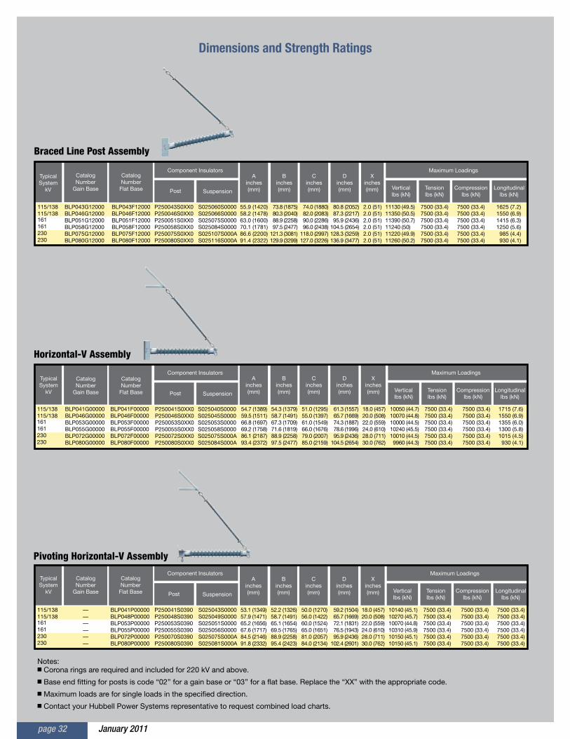
Braced Line Post Assembly
Horizontal-V Assembly
Pivoting Horizontal-V Assembly
Dimensions and Strength ratings
TypicalSystem
kV
CatalogNumber
Flat Base Post
Component Insulators Maximum Loadings
Suspension
A inches(mm)
B inches(mm)
C inches(mm)
D inches(mm)
X inches(mm) Vertical
lbs (kN)Tensionlbs (kN)
Compressionlbs (kN)
Longitudinallbs (kN)
BLP043G12000BLP046G12000BLP051G12000BLP058G12000BLP075G12000BLP080G12000
BLP043F12000BLP046F12000BLP051F12000BLP058F12000BLP075F12000BLP080F12000
P250043S0XX0P250046S0XX0P250051S0XX0P250058S0XX0P250075S0XX0P250080S0XX0
2.0 (51)2.0 (51)2.0 (51)2.0 (51)2.0 (51)2.0 (51)
7500 (33.4)7500 (33.4)7500 (33.4)7500 (33.4)7500 (33.4)7500 (33.4)
7500 (33.4)7500 (33.4)7500 (33.4)7500 (33.4)7500 (33.4)7500 (33.4)
115/138115/138161161230230
Notes:n Corona rings are required and included for 220 kV and above.
n Base end fitting for posts is code “02’’ for a gain base or “03’’ for a flat base. Replace the “XX” with the appropriate code.
n Maximum loads are for single loads in the specified direction.
n Contact your Hubbell Power Systems representative to request combined load charts.
TypicalSystem
kV
CatalogNumber
Gain Base Post
Component Insulators Maximum Loadings
Suspension
A inches(mm)
B inches(mm)
C inches(mm)
D inches(mm)
X inches(mm) Vertical
lbs (kN)Tensionlbs (kN)
Compressionlbs (kN)
Longitudinallbs (kN)
BLP041G00000BLP046G00000BLP053G00000BLP055G00000BLP072G00000BLP080G00000
BLP041F00000BLP046F00000BLP053F00000BLP055F00000BLP072F00000BLP080F00000
P250041S0XX0P250046S0XX0P250053S0XX0P250055S0XX0P250072S0XX0P250080S0XX0
10050 (44.7)10070 (44.8)10000 (44.5)10240 (45.5)10010 (44.5)9960 (44.3)
7500 (33.4)7500 (33.4)7500 (33.4)7500 (33.4)7500 (33.4)7500 (33.4)
7500 (33.4)7500 (33.4)7500 (33.4)7500 (33.4)7500 (33.4)7500 (33.4)
115/138115/138161161230230
1715 (7.6)1550 (6.9)1355 (6.0)1300 (5.8)1015 (4.5)930 (4.1)
TypicalSystem
kV Post
Component Insulators Maximum Loadings
Suspension
A inches(mm)
B inches(mm)
C inches(mm)
D inches(mm)
X inches(mm) Vertical
lbs (kN)Tensionlbs (kN)
Compressionlbs (kN)
Longitudinallbs (kN)
——————
BLP041P00000BLP048P00000BLP053P00000BLP055P00000BLP072P00000BLP080P00000
P250041S0390P250048S0390P250053S0390P250055S0390P250070S0390P250080S0390
S025043S0000S025049S0000S025051S0000S025056S0000S025075S000AS025081S000A
53.1 (1349) 57.9 (1471) 65.2 (1656)67.6 (1717)84.5 (2146)91.8 (2332)
52.2 (1326)58.7 (1491)65.1 (1654)69.5 (1765)88.9 (2258)95.4 (2423)
50.0 (1270)56.0 (1422) 60.0 (1524)65.0 (1651)81.0 (2057)84.0 (2134)
59.2 (1504)65.7 (1669)72.1 (1831)76.5 (1943)95.9 (2436)
102.4 (2601)
18.0 (457)20.0 (508)22.0 (559)24.0 (610)28.0 (711)30.0 (762)
10140 (45.1)10270 (45.7)10070 (44.8)10310 (45.9)10150 (45.1) 10150 (45.1)
7500 (33.4)7500 (33.4)7500 (33.4)7500 (33.4)7500 (33.4)7500 (33.4)
7500 (33.4)7500 (33.4)7500 (33.4)7500 (33.4)7500 (33.4)7500 (33.4)
115/138115/138161161230230
7500 (33.4)7500 (33.4)7500 (33.4)7500 (33.4)7500 (33.4)7500 (33.4)
CatalogNumber
Gain Base
CatalogNumber
Gain Base
CatalogNumber
Flat Base
CatalogNumber
Flat Base
January 2011
55.9 (1420)58.2 (1478)63.0 (1600)70.1 (1781)86.6 (2200)91.4 (2322)
73.8 (1875)80.3 (2040)88.9 (2258)97.5 (2477)
121.3 (3081)129.9 (3299)
74.0 (1880)82.0 (2083)90.0 (2286)96.0 (2438)
118.0 (2997)127.0 (3226)
80.8 (2052)87.3 (2217)95.9 (2436)
104.5 (2654)128.3 (3259)136.9 (3477)
11130 (49.5)11350 (50.5)11390 (50.7)11240 (50)11220 (49.9)11260 (50.2)
1625 (7.2)1550 (6.9)1415 (6.3)1250 (5.6)985 (4.4)930 (4.1)
S025060S0000S025066S0000S025075S0000S025084S0000S025107S000AS025116S000A
S025040S0000S025045S0000S025053S0000S025058S0000S025075S000A S025084S000A
54.7 (1389)59.5 (1511)66.8 (1697)69.2 (1758)86.1 (2187)93.4 (2372)
54.3 (1379)58.7 (1491)67.3 (1709)71.6 (1819)88.9 (2258)97.5 (2477)
51.0 (1295)55.0 (1397)61.0 (1549)66.0 (1676)79.0 (2007)85.0 (2159)
61.3 (1557)65.7 (1669)74.3 (1887)78.6 (1996)95.9 (2436)
104.5 (2654)
18.0 (457)20.0 (508)22.0 (559)24.0 (610)28.0 (711) 30.0 (762)

page 33
cAtAlOG numBEr KEy
your complete part number will be BlP075F12001
Example:
a
b
c
Assembly Type
Polymer Length
d
e
Due to the numerous variations available for braced line post assemblies, the following catalog number scheme is presented primarily
for informational
purposes. For custom-made braced line post assemblies, please refer to publication Insulator Selection Guide – Transmission (EF9091T), available via www.hubbellpowersystems.com under “Literature” > “Literature Brochures” > “Ohio Brass Insulators and Arresters.”
Please follow the instructions in the Insulator Selection Guide and return the filled-out form to your Hubbell Power Systems representative. Filling out the form with as much information as possible will ensure that our engineers receive all the critical dimensions and information needed to design your braced line post assembly. For information on braced line post assemblies not included in this catalog, please contact your HPS representative.
The first three digits define the insulator type. In this example, we
picked a Braced Line Post; therefore, we entered “BLP” in the boxes designated for “a.”
Polymer length of the line post member (in inches). The nominal polymer length (in inches) of the line post insulator is specified to help define
voltage rating of the braced line post assembly. Refer to the Horizontal Line Post Insulators table on page 21 for appropriate polymer lengths.
Fill in your selection in the boxes designated for section “b.”
For example,
if you want a Braced Line Post with a 75-inch polymer length, enter “075.”
A single letter is used to identify the type of base. Please refer to the base drawings for hole patterns and dimensions located on page 24 or page 31.
F – FlatG – GainP – Pivoting
The upsweep angle of the assembly is defined to help identify the assembly.
Typically, braced line post assemblies will have 12 degrees of upsweep
angle, and horizontal-V and pivoting-V assemblies will have 0 degrees.
Fill in your selection in the box designated for section “d” for the upsweep
angle.
For example, if you chose a braced line post assembly, enter “12.”
000 – Sequential number to address each variation or model.
Braced Line Post Insulator, 75” Line Post Polymer Length, Flat Base,
12 degrees of Upsweep Angle, Variation/Model 001 BLP075F12001
B L Pa a a b b b c d d e e e
B L P 0 7 5a a a b b b c d d e e e
Fill in your selection in the box designated for section “c.” For example, if
you want a flat base, enter “F.”
B L P 0 7 5 Fa a a b b b c d d e e e
B L P 0 7 5 F 1 2a a a b b b c d d e e e
Fill in your selection in the box designated for section “e.” In this example,
the braced line post is the first in a series, as designated by “001.”
B L P 0 7 5 F 1 2 0 0 1a a a b b b c d d e e e
Type of Line Post Base
Upsweep Angle
Internal Use
January 2011

page 34
tEcHnIcAl tErmS rEFErEncE GuIDE
AnSI – The American National Standards Institute verifies that the standard developers are complying with the consensus and all other approval criteria.
Boron-free E-Glass – Electrical grade fiberglass that has corrosion resistance greater than boron containing E-glass; it is environmentally friendly due to the lack of boron and fluorine.
combined load charts – Also referred to as application curves; a graphical representation that shows how the maximum working loads interact for a given line post or braced line post assembly.
corona – A luminous discharge resulting from ionization of the air surrounding a conductor around which a voltage gradient exceeding a certain critical value exists.
Dry Band Arcing – Electrical flashes that occur between wet and dry spots over the contaminated surface of an insulator.
E-Glass – Electrical grade fiberglass; the first glass used for high-voltage insulators.
Flashover – A disruptive discharge that is capable of breaking the insulation level provided by the air around the insulator, which creates an arc between parts of different potential or polarity.
IEc – The International Electrotechnical Commission develops and publishes international standards for all electrical technologies.
leakage Distance – The distance between the conductive end fittings of the insulator across the insulator surface, moving in and out of the sheds; also commonly referred to as the creep or creepage distance.
rcl – Reference Cantilever Load is the maximum design cantilever load (MDCL), which is rated at 50 percent of the part’s SCL.
rIV – Radio-Interference Voltages are caused by electric currents that produce magnetic and electrostatic fields that are capable of inducing high-frequency voltage pulses in nearby radio antennas. The RIV of an insulator is measured under conditions specified by industry standards.
rtV – Room Temperature Vulcanate (elastomer sealant) is a silicone rubber that cures at room temperature.
rtl – Routine Test Load is the maximum design tension load, which is rated at 50 percent of the part’s SML. All parts are tested at this rating prior to being shipped.
Section length – The straight-line distance between the coupling points of the insulator’s end fittings.
Scl – Specified Cantilever Load is the minimum ultimate cantilever strength of the part.
Sml – Specified Mechanical Load is the minimum ultimate tensile strength of the part.
Strike Distance – The shortest distance across the insulator surface, between the end fittings of the insulator; also commonly referred to as the dry arc distance or tight string distance.
January 2011

®


Web: http://www.hubbellpowersystems.comE-mail: [email protected]
MEXICOHUBBELL DE MEXICO, S.A. DE C.V.Av. Insurgentes Sur #1228, Piso 8Col. Tlacoquemacatl Del ValleMexico, D.F. 03200Phone: 52-55-9151-9999Fax: 52-55-9151-9988Website: hubbell.com.mx
UNITED STATESCANADA, INTERNATIONALHUBBELL POWER SYSTEMS, INC.210 N. Allen Street Centralia, Mo 65240-1395Phone: 1-573-682-5521Fax: 1-573-682-8714e-mail: [email protected]

®
Web: http://www.hubbellpowersystems.comE-mail: [email protected]
For reliable transmission, the World is turning to hubbell.
A&J 1MJanuary 2011