insulation clip band guide clevis - nrc
TRANSCRIPT

U-Bar Type Pipe Whip Restraint Configuration
970187.78 3.6-21Figure
Amendment 53November 1998
Form No. 960690
Draw. No. Rev.
Structure
Weld
Rod
Clearance
Insulation
Clip
Band
Guide
Clevis
PinBracket
Columbia Generating StationFinal Safety Analysis Report

Rigid Type Pipe Whip Restraint Configuration
990578.57 3.6-22.1Figure
Amendment 55May 2001
Form No. 960690
Draw. No. Rev.
Pipe
Rin
gAs
sem
bly
Stru
t Ass
embl
y
Sect
ion
A-A
C L
AA
Ref
eren
ce P
ipe
Azim
uth
0°
Stru
t
Shim
Slot
ted
Hol
es in
Supp
ort S
teel
Supp
ort S
teelSt
rut
Pipe
Flan
ge
Rin
g
Shim
C R
ing
Splic
eL
Columbia Generating StationFinal Safety Analysis Report

Rigid Type Pipe Whip Restraint Configuration
970187.79 3.6-22.2Figure
Amendment 53November 1998
Form No. 960690
Draw. No. Rev.
B
B
Typical SlottedHole in Plateand Shims Restraint
Block
Splice Plate
Support Plate
Flange
Pipe
ReferencePipe Azimuth 0°
CL
Base Plate
SupportSteel
Shim
PipeCL
Section B-BType 2 Pipe Whip Support
Shim
Columbia Generating StationFinal Safety Analysis Report

Rigid Type Pipe Whip Restraint Configuration
970187.80 3.6-22.3Figure
Amendment 53November 1998
Form No. 960690
Draw. No. Rev.
C
C
RestraintBlock
ArchPlates
SupportPlate
ReferencePipe Azimuth 0°
CL
Base Plate
SupportSteel
Shim
PipeCL
Pipe
Shim
Flange SpreaderBar
Type 3 Pipe Whip Support Section C-C
Columbia Generating StationFinal Safety Analysis Report

Pipe
Rigid Type Pipe Whip Restraint Configuration
990578.58 3.6-22.4Figure
Amendment 55May 2001
Form No. 960690
Draw. No. Rev.
C L
Type
3A
Pipe
Whi
p Su
ppor
tTy
pe 3
BPi
pe W
hip
Supp
ort
Type
3C
Pipe
Whi
p Su
ppor
t
Shim
Ref
er.
Pipe
Azi
mut
h0º
Ref
eren
ce P
ipe
Azim
uth
0°
C LPW
S
D D
Arch
Pla
tes
Res
train
tBl
ock
Stru
tTe
e
Base
Plat
e
Supp
ort
Plat
e
Flan
ge
Col
umn
Pipe
Flan
ge
Spre
ader
Bar
Shim
Shim
Ref
eren
cePi
pe A
zim
uth
0°
Base
Pla
te
Flan
ge Supp
ort
Plat
e
Base
Plat
e
Shim
Sect
ion
D-D
Supp
ort S
teel
Supp
ort S
teel
Supp
ort S
teel
Columbia Generating StationFinal Safety Analysis Report

Amendment 55May 2001
Rigid Type Pipe Whip Restraint Configuration
990578.59 3.6-22.5FigureForm No. 960690
Draw. No. Rev.
Type
4a
Pipe
Whi
p Su
ppor
t
C LPW
S
Sect
ion
E-E
F
Ref
eren
ce P
ipe
Azim
uth
0°
Type
4Pi
pe W
hip
Supp
ort
Ref
eren
ce P
ipe
Azim
uth
0°
E E
F
Sect
ion
F-F
C LPW
S
Columbia Generating StationFinal Safety Analysis Report

Amendment 55May 2001
Pipe Whip Restraint Installation -Main Steam System
990578.60 3.6-23.1FigureForm No. 960690
Draw. No. Rev.
26" P
IPE
- MAI
N S
TEAM
LOO
P 'A
'
90°
45°
35°
0°18
0°
180°·
2441
2431
2441
2431
4' -
11 3
/4" R
15' -
9 1
/8" R
C
N 1
4 (T
YP.)
RPV
SAC
RIF
ICIA
LSH
IELD
WAL
L
0° REF PIPE
26" P
IPE
- MAI
N S
TEAM
LOO
P 'B
'
C L
LPWS 32.1
CL
1.50"
PWS 31-1
CL PLAN
Columbia Generating StationFinal Safety Analysis Report

Amendment 55May 2001
Pipe Whip Restraint Installation -Main Steam System
990578.61 3.6-23.2FigureForm No. 960690
Draw. No. Rev.
C L
W14
PWS
32 -
1@ A
Z 08
°
C L26
" Mai
n St
eam
Pip
e
2431
2431
2441
2441
C L26
" Mai
n St
eam
Pip
e
W14
Sacr
ifici
alSh
ield
Wal
l
Stab
ilizer
Trus
s
Sect
ion
2431
-243
1Se
ctio
n 24
41-2
441
Columbia Generating StationFinal Safety Analysis Report

Amendment 55May 2001
Pipe Whip Restraint Installation -Main Steam System
990578.69 3.6-23.3FigureForm No. 960690
Draw. No. Rev.
CO
L W
14
Con
tain
men
t Ves
sel &
RPV
0° A
zim
uth
W14
W14
Bra
ce
2568
2564
2692
BUIL
T U
P BE
AM
CO
L W
14 +
4P
s L
INSI
DE
FAC
EC
ON
T. V
ESSE
L
27' -
10-
1/2
" TO
C
CO
NT.
VES
SEL
W8
CO
LBU
ILT
UP
MEM
BER
PLAN
L
2692
Columbia Generating StationFinal Safety Analysis Report

Amendment 55May 2001
Pipe Whip Restraint Installation -Main Steam System
010126.47 3.6-23.4FigureForm No. 960690
Draw. No. Rev.
El. 506' - 0 9/16"
El. 506' - 0 7/8"
W14
Columbia Generating StationFinal Safety Analysis Report
SECTION 2692-2692

Amendment 55May 2001
Pipe Whip Restraint Installation -Main Steam System
010126.50 3.6-23.5FigureForm No. 960690
Draw. No. Rev.
El. 5
10' -
10"
El. 5
06' -
0 1
/16" W
14W14
Valv
e
W14
W14
Col
. Stu
b
El. 5
05' -
11
13/1
6"
El. 4
99' -
6"
Col
. W14
+ 4
Ps
Sect
ion
2568
-256
8Se
ctio
n 25
64-2
564
L
Columbia Generating StationFinal Safety Analysis Report

Amendment 53 November 1998
Columbia Generating Station Final Safety Analysis Report
Pipe Whip Restraint Installation - Main Steam System
Draw. No. 020552.04 Rev. Figure 3.6-23.6

Amendment 55May 2001
Pipe Whip Restraint Installation - Main Steam andReactor Feedwater in Main Steam Tunnel
990578.68 3.6-24.1FigureForm No. 960690
Draw. No. Rev.
El. 518'-0"
El. 522'-0"
CL PWS's &Built-upMember
2"CL MS Pipe
PWS 335-2
24" o RFW PipeCL
CL Built-up MembersEl. 509'-0"
CL26" MS Pipe
El. 500'-9"
CL PWS 315-8El. 498'-7"
CL PWS andBuilt-up Member
El. 501'-0"
CL PWS 315-10
CL CL
CL
24" o RFW Pipe489'-4"
Built-up members
El. 496'-6" 30" o MSPipe El.494'-2 1/2"
Built-up memberEl. 491'-7 5/16"
CL
PWS 315-4
SECTION 4405-4405
Columbia Generating StationFinal Safety Analysis Report

Amendment 55May 2001
Pipe Whip Restraint Installation - Main Steam andReactor Feedwater in Main Steam Tunnel
010126.36 3.6-24.2FigureForm No. 960690
Draw. No. Rev.
16' -
6"
16' -
6"
7'-4
"
7'-4
"
3'-8
"3'
-8"
7'-4
"
7'-4
"
3'8"
7'-4"H
CL
CL 26" ø M.S. PipesT.G. Building Reactor Building
PWS's & Built-up Members
6
CL
26"ø M.S. Pipe &PWS 315-2
CL
24"ø RFW Pipe &PWS 335-1
CL
26"ø M.S. Pipe &PWS 315-1
CL
26"ø M.S. Pipe &PWS 315-23
CL
24"ø RFW Pipe &PWS 335-2
CL
26"ø M.S. Pipe &PWS 315-4
CL
Plan of PWS's 315-1, 315-2, 315-3315-4, 335-1 & 335-2
4405
4404
2"
24" ø RFW Pipes
Columbia Generating StationFinal Safety Analysis Report

Amendment 57December 2003
Pipe Whip Restraint Installation - Main Steam andReactor Feedwater in Main Steam Tunnel
010126.45 3.6-24.3FigureForm No. 960690
Draw. No. Rev.
Sect
ion
44
04-4
404
7'-4
"7'
-4"
C L
C L
C L C L C LBu
ilt-u
p M
embe
r & P
WS'
sEl
. 492
' - 6
13/
16"
PWS
315-
7El
. 498
' - 6
13/
16"
Built
-up
Mem
ber
El. 4
98' -
7 5
/16"
26"ø
M.S
. Pip
eEl
. 505
' - 6
1/1
6"
Top
of M
ount
ing
PEl
. 510
' - 2
1/4
"L
PWS
315-
3PW
S 31
5-4
PWS
315-
1PW
S 31
5-2
PWS
335-
2
PWS
335-
1(T
ype
3 Ty
p)
24"ø
RFW
Pip
esEl
. 512
' - 1
/2"
270°
270°
90°
Built
-Up
Mem
ber
El. 4
97' -
5/1
6"C L
Built
-Up
Mem
ber &
PWS
315-
6El
. 498
' - 7
5/1
6"
C L
26"ø
M.S
. Pip
eEl
. 505
' - 6
1/1
6"26
"ø M
.S. P
ipes
El. 5
05' -
6 1
/4"
PWS
335-
3C L
PWS
335-
5El
. 496
' - 1
1 13
/16"
PWS'
sEl
. 498
' - 7
"
Built
-up
Mem
bers
El. 4
98' -
7 1
/2"
90°
PWS
335-
4
C L
C L
C L
PWS
315-
5PW
S 31
5-8
180°
0° R
efer
ence
Pip
e Az
.0° R
efer
ence
Pip
e Az
.
LDCN-02-000
130°
Columbia Generating StationFinal Safety Analysis Report

Amendment 55May 2001
Pipe Whip Restraint Installation - Main Steam and Reactor Feedwater in Main Steam Tunnel
4.42-6.312.621010 FigureForm No. 960690
.veR.oN .warD
C L
CL
C L
30" ø M.S. Pipes
7' 6"Top of Slab EL. 501'-0"
11'-9"
4'-1 7/8" Built-up Member
Opening
Face of WallPWS 315-9
PWS
Type
3
4405
180°
4'-3"
4'-0
"
0° R
EF.
Pipe
Az.
4'-0
"
4'-0"
3'-10 7/8"8'-0"
PWS 315-10
WP EL. 494'2 1/2"
2'-0" 1'-6"
Built
-up
Mem
ber
180°
2"
270°
3 epyT SWP
0° R
efer
ence
Pip
e AZ
.EL. 501'0"
90°
7'-4"
3'-8"
24" R.F.W Pipes
4404 Concrete Wall
CL
CL
CL
90°270°
CL
CLPWS 315-9W.P. EL. 494'-1 7/8"
CL
Columbia Generating StationFinal Safety Analysis Report
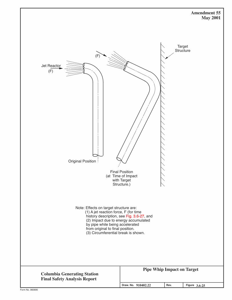
Jet Reactor
Amendment 55May 2001
Pipe Whip Impact on Target
910402.22 3.6-25FigureForm No. 960690
Draw. No. Rev.
(F)
Original Position
(F)
TargetStructure
Final Position(at Time of Impact
with TargetStructure.)
Note: Effects on target structure are: (1) A jet reaction force, F (for time history description, see Fig. 3.6-27, and (2) Impact due to energy accumulated by pipe while being accelerated from original to final position. (3) Circumferential break is shown.
Columbia Generating StationFinal Safety Analysis Report

Jet Impingement on Target
910402.23 3.6-26Figure
Amendment 53November 1998
Form No. 960690
Draw. No. Rev.
Note: For Time History DescriptionsSee Fig. 3.6-27
Jet ImpingementResultant Force (F)
TargetStructure
Circumferential Break
Longitudinal SplitIn Pipe Elbow
Pipe
TargetStructure
Jet ImpingementResultant Force (F)
Columbia Generating StationFinal Safety Analysis Report

Amendment 55May 2001
Time History of Jet Impingement and ReactionForce
990306.42 3.6-27FigureForm No. 960690
Draw. No. Rev.
Conservative Approximation
Trust Force Transient,Very Low Friction Flow
Thrust Force Transient, Friction Flow
SteadyState
Po T
A fl/D = 0
Ct
1.0
1.000
Actual Thrust
Time (Milliseconds)tss
Thru
st C
oeffi
cien
t, T/
P 0A
Po T
A
Conservative Approximation
Actual Thrust
Steady State
1.0
Ct
0tss0 1.0
fl/D > > 0
Time (Milliseconds)
Thru
st C
oeffi
cien
t, T/
P 0A
Columbia Generating StationFinal Safety Analysis Report

Structural Response to a Step Function Loading
970187.81 3.6-28Figure
Amendment 53November 1998
Form No. 960690
Draw. No. Rev.
Force
F
Time (orDisplacement)
Displacement
K
1
ResistanceForce
Rm
YeL
F
Y
m
K
Elasto-PlasticSpring
(A) Single degree of freedom mathematical idealization for a structure.
(B) Step Function Load (C) Resistance Function
Columbia Generating StationFinal Safety Analysis Report

Amendment 55May 2001
Resistance-Displacement Functions with AssociatedStructural Response (with and without Effect of
Other Loads)990306.43 3.6-29Figure
Form No. 960690
Draw. No. Rev.
ResponseResistance-
DisplacementFunction
Available StrainEnergy withoutother Loading
Available StrainEnergy with other
Loading
Elasto-Plastic
Note: Shaded Area (Strain Energy)Must Equal Es (from 3.6.1.6.3.2)
R Rm
Xe X
R = KX R Rm
Xe
R
XeXm Xm
X1
Xo
Columbia Generating StationFinal Safety Analysis Report

Rev. FigureDraw. No.Form No. 960690
Amendment 53November 1998
Columbia Generating StationFinal Safety Analysis Report
020361.14 3.6-30
Jet from Circumferential Break with Ends Restrained (Fan Jet)

Amendment 55May 2001
Design for Wall Rebound
990306.44 3.6-31FigureForm No. 960690
Draw. No. Rev.
Note: The wall rebound force isused in a direction opposite to thepipe or pipe jet impact load.
To determine Rm :
YeL2Rm2
Rm2
Rm1
Rm1
Rm2
Rm1
Rm2Rm1
YeL1
YeL2 YeL1
=
= ( )E1 = µYel2 Rm2 = ER = 1/2 yel.1 Rm1
Rm2 = 1/2 yel.1 Rm1or µYeL1
Therefore, Rm22 = 1/2µ (RM12)
or Rm2 = Rm11
2µ
)(E1
Y
YeL1
R
µYeL2
YeL2
E1 = ER
ReboundEnergy = ER
Columbia Generating StationFinal Safety Analysis Report

Amendment 55May 2001
Blowdown Mass Flow Rate from Postulated Crackin 26 in. Main Steam Line - Outside Primary
Containment in Main Steam Tunnel990306.49 3.6-61Figure
Form No. 960690
Draw. No. Rev.
.001
.01
.11.
010
.00246810
Tim
e, S
ec.
Break Mass Flow Rate, 103 lb/sec
Columbia Generating StationFinal Safety Analysis Report

Amendment 55May 2001
Energy Release Rate from Postulated Crack in 26in. Main Steam Line - Outside Primary
Containment in Main Steam Tunnel990306.51 3.6-62Figure
Form No. 960690
Draw. No. Rev.
.1Ti
me,
Sec
.
.001
.01
1.0
10.0
0246810 Energy Rate, 106 btu/sec
Columbia Generating StationFinal Safety Analysis Report

Amendment 57December 2003
Blowdown Mass Flow Rate from Postulated Crackin 24 in. Reactor Feed Line - Outside Primary
Containment in Main Steam Tunnel990306.52 3.6-63Figure
Form No. 960690
Draw. No. Rev.
.1Ti
me,
Sec
.
.001
.01
1.0
10.0
0246810 Break Mass Flow Rate, 106 lb/sec
Columbia Generating StationFinal Safety Analysis Report
LDCN-02-000

Amendment 55May 2001
Energy Release Rate from Postulated Crack in 24in. Reactor Feedwater Line - Outside Primary
Containment in Main Steam Tunnel990306.53 3.6-64Figure
Form No. 960690
Draw. No. Rev.
.1Ti
me,
Sec
.
.001
.01
1.0
10.0
0246810 Energy Rate, 106 btu/sec
Columbia Generating StationFinal Safety Analysis Report

Pressure Transient in Node 1 of Main SteamTunnel after a Postulated Main Steam Pipe Break
in Node 1 of Main Steam Tunnel970187.87 3.6-68Figure
Amendment 53November 1998
Form No. 960690
Draw. No. Rev.
10-3 10-2 10-1 10014
16
18
20
22
24
26
28
Time Sec
Aver
age
pres
sure
in N
ode
1 ps
ia A
P1
Columbia Generating StationFinal Safety Analysis Report

Amendment 53November 1998
Pressure Transient in Node 2 of Main SteamTunnel after a Postulated Main Steam Pipe Break
in Node 1 of Main Steam Tunnel970187.88 3.6-69Figure
Form No. 960690
Draw. No. Rev.
10-3 10-2 10-1 10014
16
18
20
22
24
26
28
Time Sec
Columbia Generating StationFinal Safety Analysis Report
Aver
age
Pres
sure
in N
ode
2 ps
ia A
P2

Temperature Transient in Node 1 of Main SteamTunnel after a Postulated Main Steam Pipe Break
in Node 1 of Main Steam Tunnel970187.89 3.6-70Figure
Amendment 53November 1998
Form No. 960690
Draw. No. Rev.
10-3 10-2 10-1 100200
220
240
260
280
300
320
340
Time Sec
Columbia Generating StationFinal Safety Analysis Report
Aver
age
Tem
pera
ture
in N
ode
1 De
gF A
T1

Temperature Transient in Node 2 of Main SteamTunnel after a Postulated Main Steam Pipe Break
in Node 1 of Main Steam Tunnel970187.90 3.6-71Figure
Amendment 53November 1998
Form No. 960690
Draw. No. Rev.
10-3 10-2 10-1 100200
220
240
260
280
300
320
340
Time Sec
Columbia Generating StationFinal Safety Analysis Report
Aver
age
Tem
pera
ture
in N
ode
2 De
g F
AT2

Pressure Transient in Node 1 of Main SteamTunnel after a Postulated Main Steam Pipe Break
in Node 2 of Main Steam Tunnel970187.91 3.6-72Figure
Amendment 53November 1998
Form No. 960690
Draw. No. Rev.
10-3 10-2 10-1 10014
16
18
20
22
24
26
28
Time Sec
Columbia Generating StationFinal Safety Analysis Report
Aver
age
Pres
sure
in N
ode
1 ps
ia A
P1

Pressure Transient in Node 2 of Main SteamTunnel after a Postulated Main Steam Pipe Break
in Node 2 of Main Steam Tunnel970187.92 3.6-73Figure
Amendment 53November 1998
Form No. 960690
Draw. No. Rev.
10-3 10-2 10-1 10014
16
18
20
22
24
26
28
Time Sec
Columbia Generating StationFinal Safety Analysis Report
Aver
age
Pres
sure
in N
ode
2 ps
ia A
P2

Temperature Transient in Node 1 of Main SteamTunnel after a Postulated Main Steam Pipe Break
in Node 2 of Main Steam Tunnel970187.93 3.6-74Figure
Amendment 53November 1998
Form No. 960690
Draw. No. Rev.
10-3 10-2 10-1 100200
220
240
260
280
300
320
340
Time Sec
Columbia Generating StationFinal Safety Analysis Report
Aver
age
Tem
pera
ture
in N
ode
1 De
g F
AT1

Temperature Transient in Node 2 of Main SteamTunnel after a Postulated Main Steam Pipe Break
in Node 2 of Main Steam Tunnel970187.94 3.6-75Figure
Amendment 53November 1998
Form No. 960690
Draw. No. Rev.
10-3 10-2 10-1 100200
220
240
260
280
300
320
340
Time Sec
Columbia Generating StationFinal Safety Analysis Report
Aver
age
Tem
pera
ture
in N
ode
2 De
g F
AT2

Amendment 55May 2001
Nodalization Scheme for Postulated Pipe Break inMain Steam Tunnel Extension
990306.57 3.6-76FigureForm No. 960690
Draw. No. Rev.
1
= Atmosphere
Note: Data Tabulated in Tables 3.6-13 & -14
V1 = 2320 ft3
4
EL 441 ft
V4 = 658938 ft3
3
EL 471 ft
V3 = 728610 ft3
2
V2 = 2799 ft35
6
V5 = 1270592 ft3
A35 = 507 ft2 A23 = 114.6 ft2 A13 = 73.6 ft2
A34 = 230 ft2
A56 = 1150 ft2
A 12
= 37
9 ft2
EL 501 ft
Columbia Generating StationFinal Safety Analysis Report

Pressure Transient in Node 1 of Main Steam Tun-nel Extension after a Postulated Main Steam PipeBreak in Node 1 of Main Steam Tunnel Extension
970187.95 3.6-77Figure
Amendment 53November 1998
Form No. 960690
Draw. No. Rev.
10-3 10-2 10-1 10012
14
16
18
20
22
24
26
Time Sec
Columbia Generating StationFinal Safety Analysis Report
Aver
age
Pres
sure
in N
ode
1 ps
ia A
P1

Pressure Transient in Node 2 of Main Steam Tun-nel Extension after a Postulated Main Steam PipeBreak in Node 1 of Main Steam Tunnel Extension
970187.96 3.6-78Figure
Amendment 53November 1998
Form No. 960690
Draw. No. Rev.
10-3 10-2 10-1 10012
14
16
18
20
22
24
26
Time Sec
Columbia Generating StationFinal Safety Analysis Report
Aver
age
Pres
sure
in N
ode
2 ps
ia A
P2

Temperature Transient in Node 1 of Main SteamTunnel Extension after a Postulated Main Steam
Pipe Break in Node 1 of Main Steam Tunnel Exten.970187.97 3.6-79Figure
Amendment 53November 1998
Form No. 960690
Draw. No. Rev.
10-3 10-2 10-1 100200
220
240
260
280
300
320
340
Time Sec
Columbia Generating StationFinal Safety Analysis Report
Aver
age
Tem
pera
ture
in N
ode
1 De
g F
AT1

Temperature Transient in Node 2 of Main SteamTunnel Extension after a Postulated Main Steam
Pipe Break in Node 1 of Main Steam Tunnel Exten.970187.98 3.6-80Figure
Amendment 53November 1998
Form No. 960690
Draw. No. Rev.
10-3 10-2 10-1 100200
220
240
260
280
300
320
340
Time Sec
Aver
age
Tem
pera
tture
in N
ode
2 D
eg F
AT2
Columbia Generating StationFinal Safety Analysis Report

Pressure Transient in Node 1 of Main SteamTunnel Extension after a Postulated Main Steam
Pipe Break in Node 2 of Main Steam Tunnel Exten.970187.99 3.6-81Figure
Amendment 53November 1998
Form No. 960690
Draw. No. Rev.
10-3 10-2 10-1 10012
14
16
18
20
22
24
26
Time Sec
Aver
age
Pres
sure
in N
ode
1 ps
ia A
P1
Columbia Generating StationFinal Safety Analysis Report

Pressure Transient in Node 2 of Main Steam TunnelExtension after a Postulated Main Steam Pipe Break
in Node 2 of Main Steam Tunnel Extension900547.97 3.6-82Figure
Amendment 57December 2003
Form No. 960690
Draw. No. Rev.
10-3 10-2 10-1 10012
14
16
18
20
22
24
26
Time Sec
Aver
age
Pres
sure
in N
ode
2 ps
ia A
P2
Columbia Generating StationFinal Safety Analysis Report
LDCN-02-000

Temperature Transient in Node 2 of Main SteamTunnel Extension after a Postulated Main Steam
Pipe Break in Node 2 of Main Steam Tunnel Exten.910402.25 3.6-83Figure
Amendment 53November 1998
Form No. 960690
Draw. No. Rev.
10-3 10-2 10-1 100200
220
240
260
280
300
320
340
Time Sec
Aver
age
Tem
pera
ture
in N
ode
2 De
g F
AT1
Columbia Generating StationFinal Safety Analysis Report

Temperature Transient in Node 2 of Main SteamTunnel Extension after a Postulated Main Steam Pipe
Break in Node 2 of Main Steam Tunnel Extension900547.99 3.6-84Figure
Amendment 53November 1998
Form No. 960690
Draw. No. Rev.
10-3 10-2 10-1 100200
220
240
260
280
300
320
340
Time Sec
Columbia Generating StationFinal Safety Analysis Report
Aver
age
Tem
pera
ture
in N
ode
2 D
eg F
AT2

Analytical Model
970187.84 3.6-89Figure
Amendment 53November 1998
Form No. 960690
Draw. No. Rev.
Cantilever Pipe Length(Energy Absorbing Member)
FI
FI
Gap(d)Spring (K)
Beam (Energy Absorbing Component)
LoadTransmitting
Member
Pipe WhipRestraint
Pipe
GapLoad Trans.
Member
M
Resistance(Force)
Rr
Ye
Ym
K=Rr Ye
Displacement
(C) Resistance Function
(A) Pipe Whip Support Configuration(B) Single Degree of Freedom
Mathematical Idealizationfor a Structure
Columbia Generating StationFinal Safety Analysis Report

Required Resistance of Structures (Rr)
970187.85 3.6-90Figure
Amendment 53November 1998
Form No. 960690
Draw. No. Rev.
Fi
F(t)
td t
F1
F(t)
t
+
Rr = + +µ F1(2µ-1)
u F1(2µ-1)
2 (K) (k)(2µ-1)
1/22
Impulse (i) = Fi (td)
Kinetic Energy (K) = = F1 x distance (d)
Note: µ + ; Elastic Spring Constant k =
Ref. 3.6-1 Chapter 5 paragraph 5.5b
F1 Ym + K = Rr [Ym - (1/2) Ye]
Substituting µ = & + Ye
Rr2 (µ - 1/2) - uF1 Rr - (K) (k) = 0
Solving Quadratically:
YmYe
i22M
RrYe
YmYe
Rrk
Columbia Generating StationFinal Safety Analysis Report

Fluid Jet Geometry
970187.86 3.6-91Figure
Amendment 53November 1998
Form No. 960690
Draw. No. Rev.
CL
CL
10°
CL
CL
10°
CL
L
L
W
Full Expansion Plane
(A) Circumferential Break with Full Separation
(B) Circumferential Break with Partial Separation
(C) Longitudinal Break
Break Plane
Full Expansion Plane
Region 3
Region 2
Region 1
Break PlaneFull Expansion Plane
Region 3
Region 2
Region 1
Region2
Region 3Region 1
Break Plane
L∞
L∞
L
10°
Columbia Generating StationFinal Safety Analysis Report

Thrust Versus Time - Reactor Side of Break on 4in. RCIC (13) - 4 in. Room R206
910402.06 3.6-96Figure
Amendment 53November 1998
Form No. 960690
Draw. No. Rev.
Time After Break - Sec
Blow
dow
n Th
rust
- LB
F * 1
02160
150
140
130
120
110
100
90
80
700.0 0.2 0.4 0.6 0.8 1.0 1.2 1.4
Columbia Generating StationFinal Safety Analysis Report

Thrust Versus Time - Reactor Side of Break on 4in. RCIC (13) - 4 - El. 431.8 ft
910402.07 3.6-97Figure
Amendment 53November 1998
Form No. 960690
Draw. No. Rev.
Time After Break - Sec
Blow
dow
n Th
rust
- LB
F * 1
02150
140
130
120
110
100
90
80
70
60.00 .08 .16 .24 .32 .40 .48 .56
Columbia Generating StationFinal Safety Analysis Report

Thrust Versus Time - Upstream Side of Break on4 in. RWCU (2) - 4 - El. 536 ft 0 in., Room R409
910402.08 3.6-98Figure
Amendment 53November 1998
Form No. 960690
Draw. No. Rev.
Time After Break - Sec
Blow
dow
n Th
rust
- LB
F * 1
02140
136
132
128
124
120
116
112
108
1040.0 0.4 0.8 1.2 1.6 2.0 2.4 2.8
Columbia Generating StationFinal Safety Analysis Report

Thrust Versus Time - Heat Exchanger Side ofBreak on 6 in. RWCU (2) - 4 - El. 514 ft 0 in.,
Room R308910402.05 3.6-99Figure
Amendment 53November 1998
Form No. 960690
Draw. No. Rev.
Time After Break - Sec
Blow
dow
n Th
rust
- LB
F * 1
0340
36
32
28
24
20
16
12
8
40.0 0.4 0.8 1.2 1.8 2.0 2.4 2.8
Columbia Generating StationFinal Safety Analysis Report

Thrust Versus Time - Pump Side of Break on 6 in.RWCU (1) - 4 - El. 548 ft 0 in., Room R409
910402.09 3.6-100Figure
Amendment 53November 1998
Form No. 960690
Draw. No. Rev.
Time After Break - Sec
Blow
dow
n Th
rust
- LB
F * 1
0340
38
36
34
32
30
28
26
24
220.0 0.4 0.8 1.2 1.6 2.0 2.4 2.8
Columbia Generating StationFinal Safety Analysis Report

Thrust Versus Time - Pump Side of Break onRWCU (1) - 4 - El. 556 ft 0 in., Room R510
910402.11 3.6-101Figure
Amendment 53November 1998
Form No. 960690
Draw. No. Rev.
Time After Break - Sec
Blow
dow
n Th
rust
- LB
F * 1
02330
320
310
300
290
280
270
260
250
2400.0 0.4 0.8 1.2 1.6 2.0 2.4 2.8
Columbia Generating StationFinal Safety Analysis Report

Thrust Versus Time - Downstream Side of Breakon 6 in. RWCU (6) - 4 - El. 559 ft 0 in.,
Room R510910402.12 3.6-102Figure
Amendment 53November 1998
Form No. 960690
Draw. No. Rev.
Time After Break - Sec
Blow
dow
n Th
rust
- LB
F * 1
0328
26
24
22
20
18
16
14
12
100.0 0.4 0.8 1.2 1.6 2.0 2.4 2.8
Columbia Generating StationFinal Safety Analysis Report

Thrust Versus Time - Both Sides of Break on 4 in.RWCU (1) - 4 El. 556.5 ft 0 in., Room R510
910402.13 3.6-103Figure
Amendment 53November 1998
Form No. 960690
Draw. No. Rev.
Time After Break - Sec
Blow
dow
n Th
rust
- LB
F * 1
0318
16
14
12
10
8
6
4
2
00.0 0.4 0.8 1.2 1.6 2.0 2.4 2.8
Columbia Generating StationFinal Safety Analysis Report
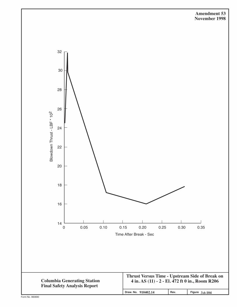
Thrust Versus Time - Upstream Side of Break on4 in. AS (11) - 2 - El. 472 ft 0 in., Room R206
910402.14 3.6-104Figure
Amendment 53November 1998
Form No. 960690
Draw. No. Rev.
Time After Break - Sec
Blow
dow
n Th
rust
- LB
F * 1
0232
30
28
26
24
22
20
18
16
140 0.05 0.10 0.15 0.20 0.25 0.30 0.35
Columbia Generating StationFinal Safety Analysis Report

Thrust Versus Time - Upstream Side of Breakon 4 in. HS (1) - 2 - El. 574.5 ft 0 in., Room R604
910402.15 3.6-105Figure
Amendment 53November 1998
Form No. 960690
Draw. No. Rev.
Time After Break - Sec
Blow
dow
n Th
rust
- LB
F1050
1000
950
900
850
800
750
700
650
6000 0.4 0.8 1.2 1.6 2.0 2.4 2.8
Columbia Generating StationFinal Safety Analysis Report

Amendment 56December 2001
Coefficients for Moment of Inertia ofCracked Sections
990306.64 3.6-106FigureForm No. 960690
Draw. No. Rev.
Icr = F bd3
1.0
10-1
10-210-2 10-1 1.0
p = bd ,As p' = bd ,A's n = EcEs
(–)P'P
1.00.750.500.250.00
Ratio pn
F = bd ,K3+ pn (l-k)2 + n (pn) P K - d 2P' d'( )2n-1 ( )
2n-1n ~ 1.9,=
d'd ~ 0.10,= k = -m + (m2 + 2q) 1/2
m = pn (1 + 1.9 p ), q = pn (1 + 0.19 p )p' p'
Coe
ffici
ent F
Columbia Generating StationFinal Safety Analysis Report
LDCN-01-00A

COLUMBIA GENERATING STATION Amendment 59 FINAL SAFETY ANALYSIS REPORT December 2007
LDCN-05-009 3.7-1
3.7 SEISMIC DESIGN All structures, systems, and components (SSCs) of the facility are defined as either Seismic Category I or non-Category I. The non-Category I seismic features are also referred to in other sections of this report as Seismic Category II. The requirements for Seismic Category I qualification are given in Section 3.2 along with a list of SSCs that are so categorized. All SSCs related to plant safety are designed to withstand the effects of the safe shutdown earthquake (SSE) and the operating basis earthquake (OBE). The SSE is that earthquake which is based on an evaluation of the maximum earthquake potential considering the regional and local geology and seismology and specific characteristics of local subsurface material. It is that earthquake which produces the maximum vibratory ground motion for which certain SSCs are designed to remain functional. These SSCs are those necessary to ensure
a. The integrity of the reactor coolant pressure boundary, b. The capability to shut down the reactor and maintain it in a safe shutdown
condition, or c. The capability to prevent or mitigate the consequences of accidents which could
result in potential offsite exposures comparable to the exposure limits of 10 CFR Part 50.67.
The OBE is that earthquake which, considering the regional and local geology and seismology and specific characteristics of local subsurface material, could reasonably be expected to affect the plant site during the operating life of the plant. It is that earthquake which produces the vibratory ground motion for which those features of the nuclear power plant necessary for continued operation without undue risk to the health and safety of the public are designed to remain functional. The OBE amplitude equals 50% the SSE amplitude. Geological and seismic criteria related to the site are given in Section 2.5. Based on these criteria the characteristics and intensity of the postulated SSE are established. 3.7.1 SEISMIC INPUT 3.7.1.1 Design Response Spectra The vibratory ground motion produced by the SSE is defined by design response spectra corresponding to the maximum vibratory accelerations at the elevations of the foundations of the nuclear power plant structures. The design response spectra are idealized, smooth curves relating the response of the foundations of the nuclear power plant structures to the vibratory

COLUMBIA GENERATING STATION Amendment 53 FINAL SAFETY ANALYSIS REPORT November 1998
3.7-2
ground motion, considering such foundations to be single-degree-of-freedom damped oscillators and neglecting soil-structure interaction effects. The vibratory ground motion produced by the OBE is also defined by design response spectra. Figures 3.7-1 and 3.7-2 show the design response spectra for the horizontal and vertical components, respectively, of ground motion associated with the SSE, for damping coefficients of 0.5, 2.0, 5.0, 7.0, and 10.0% of critical damping. The maximum horizontal ground acceleration for the SSE was selected to equal 0.25g, as described in Section 2.5, where g is acceleration of gravity. The peak ground acceleration in the vertical direction is taken as two-thirds of the horizontal value. The amplification values (and associated frequency ranges) in the design response spectra correspond to those of Newmark and Hall (Reference 3.7-1) with the exception that for 0.5, 2.0, and 5.0% of critical damping the amplification values were set at 4.8, 3.6, and 2.4, respectively. These response spectra correspond to design response spectra considered acceptable for soil sites (References 3.7-1 and 3.7-2). These design response spectra are not identical to the design response spectra as defined in Regulatory Guide 1.60, Revision 1, scaled to 0.25g maximum horizontal ground acceleration. However, the latter are used with higher damping values as defined in Regulatory Guide 1.61, Revision 0. A response spectrum dynamic modal analysis was performed on the reactor building structure for an SSE input earthquake using (a) the design response spectra defined in Figure 3.7-1 and the damping values of Table 3.7-1, and (b) the design response spectra, scaled to 0.25g maximum horizontal ground acceleration, and damping values defined in Regulatory Guides 1.60, Revision 1, and 1.61, Revision 0, respectively. The structural responses of each of these modal analyses were within 10% of each other at almost all locations. Figures 3.7-3 and 3.7-4 show the design response spectra for the horizontal and vertical components, respectively, of ground motion associated with the OBE, for damping coefficients of 0.5, 2.0, 5.0, 7.0, and 10.0% of critical damping. The ordinates of these spectra represent one-half of the ordinates of the design response spectra associated with the SSE. Both earthquakes are of 15 sec duration. This is justified because (a) most records show a short period (10 to 20 sec) of high intensity acceleration, (b) the structural response analysis indicates that the low intensity build-up and phase-out periods preceding and following the high intensity acceleration period have no significant effect on structural response, and (c) the 15 sec duration is long enough to incorporate at least 7.5 cycles of motion at frequencies above 0.5 cps which is considered a representative limit for flexible structures. 3.7.1.2 Design Time History A synthetic record of strong motion earthquake acceleration which reproduces the frequency content displayed in Figures 3.7-1 through 3.7-4 was developed (see Figure 3.7-5) by using a mathematical model described by Shinozuka (Reference 3.7-3). It consists of a duration T

COLUMBIA GENERATING STATION Amendment 53 FINAL SAFETY ANALYSIS REPORT November 1998
3.7-3
(T was set at 15 sec) of a stationary Gaussian process with zero mean and a specified auto-correlation function which corresponds to the mean-square spectral density function. The italicized information is historical and was provided to support the application for an operating license.
( )S S
g
g g g
( )ωω ω ζ ω ω
=− +2 2 2 2 2 24
(Eq.3.7.1.2-1)
where ωg, ζg and S are positive parameters which will be determined such as to conservatively represent the frequency content of the ground acceleration displayed in Figures 3.7-1 through 3.7-4. This mathematical model with zero mean and the mean-square spectral density function defined by equation (3.7.1.2-1) was simulated by way of the following series:
( )&&x t s 2N
N cos w t f
k 1
g
1 2
k k( )
=
/
=
∑
+ (Eq. 3.7.1.2-2)
where, &&x (t)g is the mathematical model of earthquake acceleration (a Gaussian random
process defined above), and
σ ω ω=
−∞
+∞
∫ Sg ( )./
d1 2
(Eq. 3.7.1.2-3)
is the standard deviation of the process &&x (t)g ; ωk( =1,2,...,N) are independent random
variables identically distributed with the density function g(ω) = g(ωk) obtained by normalizing Sg (ω)
g Sg( ) ( ) /ω ω σ= 2 (Eq. 3.7.1.2-4)
and φK are independent random variables identically distributed with the uniform density 1/2π
between 0 and 2π. The sample function, &&x (t)g , which was chosen to represent the random process xg (t) was
corrected and optimized locally. The response spectra derived from the synthetic record of earthquake acceleration envelope the design response spectra at all damping values used in the design. The comparisons of the synthetic and design response spectra are shown in Figures 3.7-6 through 3.7-10 for the

COLUMBIA GENERATING STATION Amendment 53 FINAL SAFETY ANALYSIS REPORT November 1998
3.7-4
horizontal component of the OBE. The spectra were calculated at a set of discrete values for circular frequency (ωo, ωor, ωor2,..., ωorn-1) forming a geometric progression. To ensure that the error due to the harmonic component of the simulated earthquake acceleration which contributes most to the response spectrum value is limited to 10%, the ratio of the geometric progression, r, was taken equal to 1.0196 for the damping coefficient of 2.0% of critical damping. This ratio corresponds to a period interval varying from 0.003 sec at a period of 0.03 sec to 0.010 sec at a period of 0.50 sec. The same intervals were used in computing the response spectra at other damping values. 3.7.1.3 Critical Damping Values The specific percentage of critical damping values used in dynamic analysis for Category I SSCs are shown in Table 3.7-1 and are based on the recommendations of Reference 3.7-1. Damping values for foundation materials (soils) are also shown in Table 3.7-1. 3.7.1.4 Supporting Media for Seismic Category I Structures Table 3.7-2 provides a description of the foundation/supporting media for Seismic Category I structures. All of the buildings/structures shown in Table 3.7-2 have independent foundations. Bedrock was encountered at approximately 525 ft beneath the plant grade (+440 ft 6 in. msl). See Section 2.5 for soil layering characteristics, shear wave velocity, shear modulus, and soil density. 3.7.2 SEISMIC SYSTEM ANALYSIS Analysis of Seismic Category I SSCs is accomplished by using either the response spectrum method or the time-history method. The results obtained by the response spectrum method of dynamic analysis were used in the design of Seismic Category I structures. Seismic Category I structures were also analyzed by the time-history method of dynamic analysis, using as input a synthetic record of strong motion earthquake acceleration as defined in Section 3.7.1. The results of this analysis are used to generate seismic response spectra for the design and analysis of Seismic Category I systems and components housed in these structures. Alternately, the time histories of structural response at points of attachments/supports of components are used as input in the analysis of systems and components. In the case of Seismic Category I systems and components, the equivalent static load method and dynamic tests are used when conditions allow or require them as described below. Analysis of Seismic Category I SSCs considers the following stress-producing earthquake effects:
a. Inertia forces determined by a dynamic analysis, and

COLUMBIA GENERATING STATION Amendment 53 FINAL SAFETY ANALYSIS REPORT November 1998
3.7-5
b. Effects due to differential support displacement, where applicable.
The allowable stress, load combinations, and deformation limits are those set forth in the appropriate codes and design standards which are summarized in Sections 3.8, 3.9, and 3.10. 3.7.2.1 Seismic Analysis Methods 3.7.2.1.1 Introduction Modeling procedures allow the equations of motion of a system to be written as a finite set of simultaneous ordinary differential equations. There are two approaches to the solution of the equations of dynamic equilibrium: the mode-superposition method and the direct integration method. The former was used in the original seismic analysis. It generally consists of two steps, the solution of the characteristic value problem represented by the free vibration response of the system and the transformation to normal coordinates utilizing the mode shapes of the system. This procedure uncouples the equations of motion so that the response of the system in each individual mode may be evaluated independently. Thus, the problem becomes one of solving independent differential equations rather than a set of simultaneous differential equations and, since the system is linear, the principle of superposition holds, and the total response of the system is determined by summing the responses of the individual modes. 3.7.2.1.2 The Equations of Dynamic Equilibrium The equations of motion of a multi-degree-of-freedom discrete mass damped system subjected to an arbitrary ground motion assuming velocity proportional damping, are expressed in matrix form as follows: m v(t) + c v(t) + k v(t) = -m IO&& & && ( )v tg (Eq. 3.7.2.1-1)
where m = Mass matrix c = Damping matrix k = Stiffness matrix IO = Unit vector
&&v (t)g = Ground acceleration
v(t), v(t), and v(t)& && = Matrices of displacements, velocities. and
accelerations, respectively.

COLUMBIA GENERATING STATION Amendment 53 FINAL SAFETY ANALYSIS REPORT November 1998
3.7-6
3.7.2.1.3 Solution of the Equations of Dynamic Equilibrium by Direct Integration The direct integration method was not used. 3.7.2.1.4 Solution of the Equations of Dynamic Equilibrium by Mode-Superposition The solutions to the dynamic equilibrium equations used orthogonality relations and expressing the displacements, velocities, and accelerations in terms of generalized coordinates, (i.e., v(t) = Y(t), v(t) = Y(t), v(t) = Y(t),φ φ φ& && & && & ) Equation 3.7.2.1-1 is rewritten as the following
uncoupled, normal equations of motion:
M Y t d Y t K Y t M v tr r r r r r r r r g&& ( ) & ( ) ( ) && ( )+ + =2 ω ψ (Eq. 3.7.2.1-2)
where M mr r
Tr= φ φ = Generalized mass for the rth mode;
d c
m r
rT
r2
r rT
r
=φ φ
ω φ φ
= Damping ratio of the rth mode (damping ratio for the rth mode is obtained using a weighted average as described in Section 3.7.1)
ψφ
φ φφ
r
rT
rT m
= m I
r
= Participation factor for the rth mode;
ω r = undamped circular frequency of the rth mode; Y(t) = time dependent normal coordinate vector; φr = mode shape matrix for the rth mode;
φ rT = transpose of φ r .
The undamped circular frequencies, ω , are calculated from
[ ]k m− =ω 2 0 (Eq. 3.7.2.1-3)
and the mode shape matrix for the rth mode is obtained from
[ ]k mr r− =ω φ2 0 (Eq. 3.7.2.1-4)

COLUMBIA GENERATING STATION Amendment 53 FINAL SAFETY ANALYSIS REPORT November 1998
3.7-7
The solution of the differential equation 3.7.2.1-2, for the case of at-rest initial conditions is
[ ]
Y tv e r r
t d
rr
r r go
tt
r
( )&& ( )
( )
( )
=−
− −
∫ − −
ψ
ω λ τ
ω λ τ τ
λ ω τ1
1
2
2 sin r
(Eq. 3.7.2.1-5)
For small damping ratios, λr, the above solution is approximated by:
[ ]Y t v e r r t
t d
rr
rg
o
t
( ) && ( )( )
( )
=− −
−
∫ψω τ
λ ω τ
ω τ τ sin r
(Eq. 3.7.2.1-6)
There are two methods of dynamic analysis that were used to solve the multi-degree-of-freedom problems: the response spectrum method and the time-history method. 3.7.2.1.5 Response Spectrum Method of Analysis If the design earthquake is specified in terms of a response velocity spectrum, Equation 3.7.2.1-6 becomes
Y tS
rr vr
r
( ) max =ψω
(Eq. 3.7.2.1-7)
where: Svr = Spectral velocity for the rth mode
[ ]S v e r r tt dvr g r
o
t
=− −
−∫ && ( )( )
sin ( ) maxτλ ω τ
ω τ τ (Eq. 3.7.2.1-8)
The maximum modal displacements, vr max
, for the rth mode is
vS
r rr vr
rmax= φ
ψω (Eq. 3.7.2.1-9)
where Svr = spectral velocity for the rth mode. If the design earthquake is specified in terms of a response acceleration spectrum instead of a velocity spectrum, the maximum modal displacements, vr max
, of the structure for the rth mode
are

COLUMBIA GENERATING STATION Amendment 53 FINAL SAFETY ANALYSIS REPORT November 1998
3.7-8
v S
r rr ar
rmax
= φψω 2 (Eq. 3.7.2.1-10)
where Sar = Spectral acceleration for the rth mode. The maximum modal inertia forces, Fr max
, for the rth mode are computed from
F kr max max
= v r (Eq. 3.7.2.1-11)
When the maximum modal displacements and modal inertia forces are known, the other modal quantities such as shears and moments are computed for each mode by conventional structural analysis procedures. 3.7.2.1.5.1 Combination of Modal Response. In a response spectrum modal dynamic analysis, if the modes were not closely spaced (i.e., if the frequencies differ from each other by more than 10% of the lower frequency), the modal responses were combined by the square-root-of-the-sum-of-the-squares (SRSS) method as described in Section 3.7.2.1.5.1.1. If two or more frequencies differ from each other by less than 10%, their modal responses were first combined by the absolute sum method and then combined with other individual modal responses by the SRSS method. For some nuclear steam supply system (NSSS) equipment, a double sum method, as described in Section 3.7.2.1.5.1.2 was used to evaluate the combined response. In a time-history method of dynamic analysis, the vector sum at every step was used to calculate the combined response. The use of the time-history analysis method precluded the need to consider closely spaced modes. 3.7.2.1.5.1.1 Square Root-of-the-Sum-of-the-Squares Method. Mathematically, this SRSS method is expressed as follows:
Ri
n
=
=∑ (Ri )
/2
1
1 2
(Eq. 3.7.2.1-12)
where:
R = Combined response Ri = Response in the ith mode n = Number of modes considered in the analysis.
3.7.2.1.5.1.2 Double Sum Method. This method is defined mathematically as
COLUMBIA GENERATING STATION Amendment 53 FINAL SAFETY ANALYSIS REPORT November 1998
3.7-9
R Rsk
N
ks=
∑∑
=
R ks=1
N
1
1 2
ε/
(Eq. 3.7.2.1-13)
where
R = Representative maximum value of a particular response of a given element to a given component of excitation
Rk = Peak value of the response of the element due to the kth mode N = Number of significant modes considered in the modal response combination Rs = Peak value of the response of the element attributed to sth mode
where:
( )( )ε
ω ωρ ω β ωks
k s
k k s s= +
−+
−
12 1
in which:
[ ]ω ω βk k k= −1 2 1 2/
β βωk k
d kt= + 2
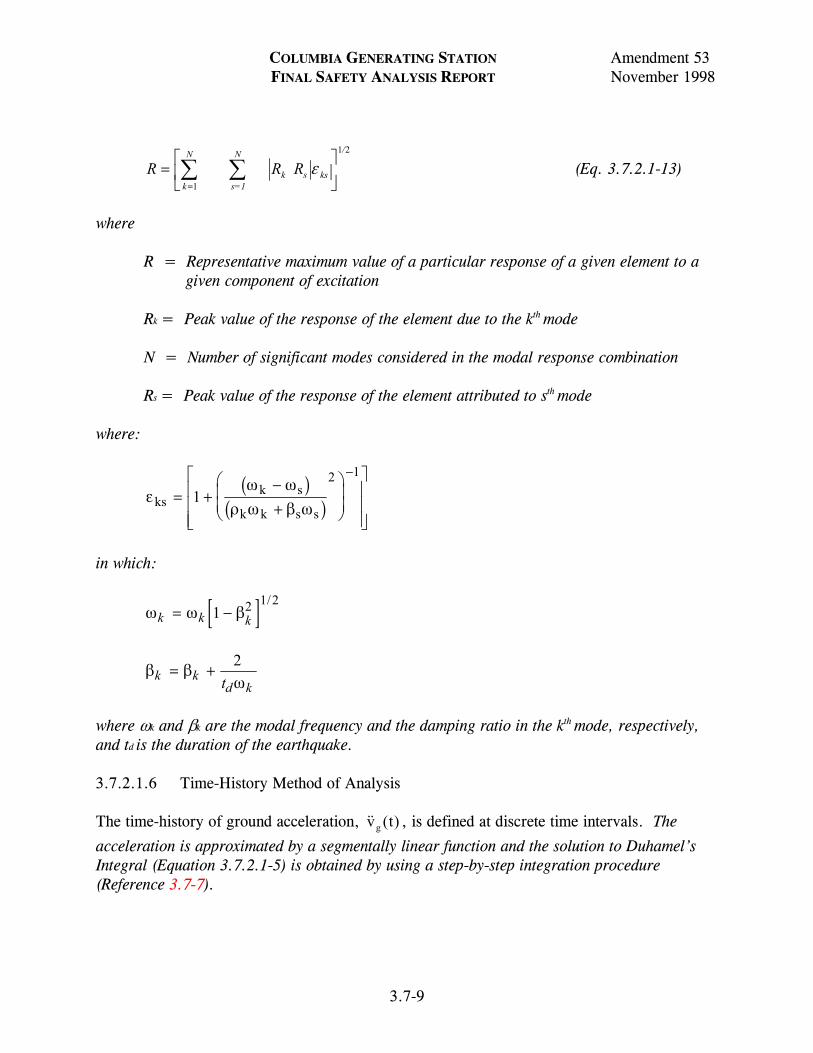
where ωk and βk are the modal frequency and the damping ratio in the kth mode, respectively, and td is the duration of the earthquake. 3.7.2.1.6 Time-History Method of Analysis The time-history of ground acceleration, && ( )v tg , is defined at discrete time intervals. The
acceleration is approximated by a segmentally linear function and the solution to Duhamel’s Integral (Equation 3.7.2.1-5) is obtained by using a step-by-step integration procedure (Reference 3.7-7).

COLUMBIA GENERATING STATION Amendment 53 FINAL SAFETY ANALYSIS REPORT November 1998
3.7-10
Yr(t) is computed as a function of time for r = 1,2,3,...,n, where n is the number of significant modes of the system. The modal displacements, v tr ( ) , at the time t for the rth mode, are then
calculated from
v t Y tr r r( ) ( )= φ (Eq. 3.7.2.1-14)
The total displacements, v t( ) , of the structure at any time, t, are obtained by adding the
individual modal displacements at time t:
v t v t v t v tn( ) ( ) ( ) ( )= + + +1 2 L (Eq. 3.7.2.1-15)
The inertia forces, F tr ( ) , at time t, for the rth mode are determined from
F t k v tr ( ) ( )= r (Eq. 3.7.2.1-16)
The total inertia forces, F t( ) , on the structure at any time t, are obtained by adding the
individual modal inertia forces at time t.
F t F t F t t( ) ( ) ( ) ( )= + +1 2 + FnL (Eq. 3.7.2.1-17)
Once the time-histories of the displacements and inertia forces have been determined, the time-histories of internal forces, such as shears and moments, for each mode are determined by conventional structural analysis procedures. The total internal forces are obtained by adding the internal forces from each mode at each increment of time. For example, the matrix of the desired moments, M t( ) , is calculated from
M t M t M t t( ) ( ) ( ) ( )= + +1 2 + MnL (Eq. 3.7.2.1-18)
where M t M tn1( ), , ( )L are the time-histories of moments in the individual modes. The
maximum values of the internal forces are determined and used for design. 3.7.2.1.7 Analysis for Differential Support Displacements Certain Seismic Category I systems (piping runs, electrical raceways and supports, duct runs, etc.), and particularly those spanning between different structures are subject to differential support displacements. Seismic Category I system components so effected are analyzed for such effects. The relative support displacements are obtained from the dynamic analysis of structures and are imposed on the systems analyzed thus determining through a static analysis the additional stresses due to relative support displacements.

COLUMBIA GENERATING STATION Amendment 53 FINAL SAFETY ANALYSIS REPORT November 1998
3.7-11
Stresses due to relative displacements of supports for piping runs are combined with other stresses as described in Section 3.9.3.1.1.7. For Seismic Category I raceways and cables spanning between different structures subject to differential movements, a flexible transition is made in the system. The transition includes a slack section in cables and a flexible section in the raceways. The slack in the cable sections and flexibility in the raceway sections are sufficient to accommodate the expected differential movements. Conduit crossing expansion joints or vibration joints in concrete slabs are provided with suitable vibration or expansion fittings to compensate for the building vibration, expansion, and contraction. For Seismic Category I ductwork spanning between different structures subject to differential movements, a flexible transition is made. The transition includes a slack section in the ductwork and sufficient flexibility in the system to accommodate the expected differential movements. 3.7.2.1.8 Dynamic Analysis of Seismic Category I Structures, Systems, and Components Seismic Category I SSCs are analyzed for earthquake effects using either response spectrum or time-history methods of analysis. 3.7.2.1.8.1 Dynamic Analysis of Buildings. All Seismic Category I structures were analyzed by the response spectrum method of analysis and the results of the analyses were used in the design of these structures. Modal maxima were combined as described in Section 3.7.2.1.5. Seismic Category I structures for which floor response spectra are required were also analyzed by the time-history method of analysis. The analyses were performed assuming the horizontal ground motion to act in either of two orthogonal directions, North-South and East-West. Maximum stresses resulting from any one horizontal and the vertical excitations were considered to act simultaneously and were added using the absolute sum method. 3.7.2.1.8.2 Dynamic Analysis of Piping Systems. Each pipe line was idealized by a mathematical model consisting of lumped masses connected by elastic members. The stiffness matrix for the piping system was determined using the elastic properties of the pipe. This includes the effects of torsion, bending, shear, and axial deformations as well as change in stiffness due to curved members. The mode shapes and the undamped natural frequencies were determined. The dynamic response of the system was calculated by using either the response spectrum or time-history method of analysis. When the piping system is anchored and supported at points with different excitations, the response spectrum analysis was performed using the envelope response spectrum of all attachment points. Alternatively, the multiple excitation analyses methods may be used where acceleration time histories or response spectra are applied to all piping system attachment points.

COLUMBIA GENERATING STATION Amendment 53 FINAL SAFETY ANALYSIS REPORT November 1998
3.7-12
The analyses were performed assuming the horizontal ground motion to act in either of two orthogonal directions, North-South or East-West. Any one of the horizontal and vertical excitations were considered to act simultaneously. Moments and forces from each of the horizontal and vertical excitations considered, are added as described in C.3 discussion for Regulatory Guide 1.92. The relative displacements between anchors were determined from the dynamic analysis of the structures. These relative displacements are then used in a static analysis to determine the additional stresses imposed on the piping system. An alternate simplified method of dynamic analysis was used for cold and/or limber piping systems. This is the equivalent static load method for piping. This method consists of applying constant horizontal and vertical load factors conservatively derived from seismic floor response spectra. The description of the method is as follows: Enveloped seismic building response spectra were derived from widened seismic floor response spectra. (The widening of the building response spectra is described in Section 3.7.2.5). The piping system was then supported seismically such that the minimum fundamental frequency was chosen to be above the spectral peak of the enveloped response spectrum for any given span of pipe between adjacent supports. Thus, the initial maximum seismic support spans were analytically determined from this model for the chosen fundamental frequency. The static “g” levels acting on the piping system were then obtained from the enveloped response spectra assuming that the frequencies of the piping system is at or above the chosen frequency. These maximum spans were modified, if required, so that the maximum stresses did not exceed a conservative value of maximum stress based on the American Society of Mechanical Engineers (ASME) Code allowables and a limiting piping deflection between supports. In the application of the alternate simplified method, a conservative static “g” loading was chosen for all piping systems when this approach was used irrespective of the building or building elevation. This simplified the work and results in different amounts of conservatism for different piping systems. To confirm the adequacy of the alternate simplified method, a study was performed for several representative piping systems. Pipe stress and pipe support loads were calculated for these representative systems using response spectrum analysis method. Results were examined to confirm that both pipe stresses and pipe support loads were calculated using the equivalent static load method. 3.7.2.1.8.3 Dynamic Analysis of Equipment. Equipment is idealized by a mathematical model consisting of lumped masses connected by elastic members or springs. Results for selected Seismic Category I equipment are given in Table 3.9-2. The dynamic response of the system was originally calculated by using the response spectrum method of analysis. When the equipment is supported at two or more points at different elevations, the response spectrum

COLUMBIA GENERATING STATION Amendment 53 FINAL SAFETY ANALYSIS REPORT November 1998
3.7-13
analysis was performed by using the response spectra at the elevation near the center of gravity of the equipment as the design spectra for the NSSS equipment, and for balance-of-plant using the envelope of response spectra for supports. Modal maxima were combined as described in Section 3.7.2.1.5. The analyses were performed assuming the horizontal ground motion to act in either of two orthogonal directions, North-South and East-West. Maximum stresses resulting from any one horizontal or vertical excitation are considered to act simultaneously and the absolute values are added directly, as described in Sections 3.7.2.6 and 3.7.2.7. The relative displacements between anchors are determined from the dynamic analysis of the structures. All cases of relative displacement between anchors are considered. If significant, these relative displacements are then used in a static analysis to determine additional stresses imposed on equipment. Further details are given in Section 3.7.2.1.8.3.1 for the NSSS equipment and Section 3.7.3.9 for all other equipment. The cases where the relative displacements between anchors are insignificant and thus neglected in the analysis are those cases where the equipment is supported on a single structural element as a floor slab or wall. Typical examples where relative displacements are considered insignificant are a bank of electrical switchgear located on and anchored to a single floor slab, a diesel generator set located on and anchored to a single isolated foundation, and an air handling unit located on and anchored to a single wall. 3.7.2.1.8.3.1 Differential Seismic Movement of Interconnected Components. The procedure for considering differential displacements for equipment anchored and supported at points with different displacement excitation is as follows. Relative displacement between the supporting points induces additional stresses in the supported equipment. These stresses can be evaluated by performing a static analysis where each supporting point is displaced a prescribed amount. From the dynamic analysis of the complete structure, the time history of displacement at each supporting point is available. The maximum relative displacements obtained from the time history were used to calculate stresses statistically. In the static calculation of the stresses due to relative displacements in the response spectrum method, the modal relative displacement was used. The mathematical model of the equipment was then subjected to the modal relative displacement at its supporting points. This procedure was repeated for the significant modes (modes contributing most to the total displacement response at the supporting point) of the structure. The total stress due to relative displacement was obtained by combining the modal results using the method described in Section 3.7.2.1.5.1. When a component is covered by the ASME Boiler and Pressure Vessel (B&PV) Code, the stresses due to relative displacement as obtained above are treated as secondary stresses.

COLUMBIA GENERATING STATION Amendment 53 FINAL SAFETY ANALYSIS REPORT November 1998
3.7-14
3.7.2.1.9 Equivalent Static Load Method This method of analysis is used for design of certain systems:
a. Unless otherwise justified, for systems which can be realistically represented by a simple model, the equivalent static acceleration corresponds to the response spectrum value at the system natural frequency times a factor of 1.5 providing the spectrum is single peaked. If the response spectrum has multiple peaks and the natural frequency lies between two peaks or below a peak, the equivalent static acceleration corresponds to the highest peak located above the natural frequency times a factor of 1.5. If the natural frequency of the system is not known, the equivalent static acceleration corresponds to the response spectrum peak (highest) times a factor of 1.5. If the system natural frequency is at or above the zero period acceleration (ZPA) of the response spectrum, the equivalent static acceleration is the ZPA with no multiplication factor required.
b. Equivalent static load method for piping is described in Section 3.7.2.1.8.2.
3.7.2.1.10 Dynamic Testing When certain Seismic Category I equipment and components potential functional failure cannot be evaluated analytically (i.e., when structural integrity alone cannot ensure the design intended function), dynamic testing is used to ensure operability. For example, dynamic tests of electrical items are performed in accordance with the requirements of IEEE Standard 344 (Reference 3.7-8). Test performance data and results are obtained either from previously tested comparable equipment or from the actual testing of equipment supplied. When seismic testing is impractical, a combination of test and analysis is used. Other dynamic test procedures which conservatively simulate the seismic conditions for the equipment are also used when found acceptable by the engineer. Seismic Category I equipment which is difficult to represent by a mathematical model or which is required to demonstrate its ability to remain operating without changing the mode of its operation (such as level switch which should not switch from “on” to “off” or vice versa during the earthquake) was subjected to actual vibration inputs on shake tables. These shake tests were performed by qualified laboratories. The seismic qualification tests conducted in the laboratory generally consist of the following:
a. The equipment was mounted on the shake table in such a manner as to represent its installed condition;
b. Sine sweep tests were performed covering all practicable frequency ranges with
constant or variable acceleration levels to determine the natural resonant

COLUMBIA GENERATING STATION Amendment 53 FINAL SAFETY ANALYSIS REPORT November 1998
3.7-15
frequencies of the equipment. This procedure enables the determination of the predominant resonant frequencies, by monitoring the output response; and
c. Proof testing was then performed to establish the capability of equipment to
function during the particular seismic event and withstand the effects of the particular seismic event, represented by the required response spectra at the appropriate damping level. This was accomplished by using one of the following methods. 1. Sine dwell tests
This test utilizes a sine wave function with one of the equipment natural frequencies and acceleration levels equal to or greater than the corresponding maximum floor acceleration as input. The test duration is generally 30 sec, during which time the behavior of the equipment is observed and recorded. This test is performed at all equipment resonances and at frequencies spaced apart throughout the frequency range. Alternately, the test may be performed only at the equipment resonances when justified.
2. Sine beat tests
A sine beat function with the number of beats and cycles per beat corresponding to the equipment natural frequency and with predetermined acceleration level equal to or greater than the corresponding maximum floor acceleration, is used as input motion to test and record the behavior of the equipment.
3. Random motion tests
A random waveform motion consisting of frequency bandwidths one-third octave apart over the practicable frequency range is used in this test. The amplitude of each frequency bandwidth is independently adjusted in each axis until the test response spectra exceeds the required response spectra. The behavior of the equipment was observed and recorded to ensure its capability to withstand the input vibrations.
3.7.2.2 Natural Frequencies and Response Loads A summary of natural frequencies, natural mode shapes, and modal responses (displacements, accelerations, moments, and shears) were provided for the significant modes of the reactor building and are shown in Figure 3.7-11 and Tables 3.7-3 through 3.7-15. The modal responses are for the OBE and SSE, for one horizontal (North-South) and the vertical

COLUMBIA GENERATING STATION Amendment 53 FINAL SAFETY ANALYSIS REPORT November 1998
3.7-16
directions. All Seismic Category I structures were also analyzed by the time-history method of analysis, using as input the synthetic motion obtained as described in Section 3.7.1.2, to develop floor response spectra to be used in design of systems, components, and equipment housed in these structures. Floor response spectrum curves were computed at all lumped-mass points of Seismic Category I structures as described in Section 3.7.1.1. These curves are for the SSE and the OBE, for two horizontal orthogonal (North-South and East-West) and the vertical directions, with equipment damping values of 0.5, 1, 2, and 5 of critical damping and for equipment natural periods ranging from 0.03 to 2.50 sec per cycle. Typical floor response spectra are shown in Figures 3.7-12 and 3.7-15 through 3.7-21 for the reactor building at refueling floor and mat elevations. 3.7.2.3 Procedure Used for Modeling Seismic Category I SSCs were modeled as a system of lumped masses and springs suitable for mathematical analysis. Each system analyzed is thus replaced by a discrete set of lumped masses, springs, and dashpots, idealizing both the inertia and stiffness properties of the system. The details of the mathematical models are determined by the complexity of the actual structure and the information required for the analysis. Seismic subsystems, such as equipment and piping [with the exception of the reactor pressure vessel (RPV)], were decoupled from the structure as described in Section 3.7.2.3.1 by lumping their mass contribution to the structural model. The seismic subsystems were then analyzed separately using the seismic input from the analysis of the structure. Where a subsystem is comparatively rigid and rigidly connected to the primary system, only the mass of the subsystem at the support point is included in the primary system model. Where the subsystem is flexible, such as pipe supported by hangers or equipment mounted on nonrigid supports, a coupled dynamic analysis was performed for both the subsystem and primary system. The criteria used for decoupling piping systems, other than the NSSS piping systems, to establish the analytical models for seismic analysis are discussed in Section 3.9.3.1.18.5, and have been demonstrated as equivalent to the decoupling criteria outlined by Paragraph II.36 of Reference 3.7-15. The criteria for the NSSS main steam and recirculation piping systems are discussed below. For NSSS systems and components, the ASME B&PV Code Section III requires that piping systems be designed and analyzed as complete systems from anchor to anchor. A complete piping system must include the subject piping system, all major branch line piping, and all equipment reached to the pipe which influences stresses and movement of the pipe. The piping systems within the General Electric contractual scope for which seismic analysis is performed are as follows:

COLUMBIA GENERATING STATION Amendment 53 FINAL SAFETY ANALYSIS REPORT November 1998
3.7-17
a. Main steam piping from the RPV in the first anchor at the penetration head fittings, and
b. Reactor recirculation piping bound by the RPV nozzles.
The criteria employed for decoupling the main steam and recirculation piping systems to establish the analytical models for seismic analysis are given below:
a. Small branch lines (6 in. diameter and less) are decoupled from the main steam and recirculation piping systems and analyzed separately; and
b. The stiffness of all the anchors and its supporting steel is large enough to
effectively decouple the piping on either side of the anchor for analytic code jurisdiction boundary purposes. The RPV is very stiff compared to the piping system and, therefore, during normal operating conditions, the RPV is assumed to act as an anchor. Penetration assemblies (heat fitting) are also stiff compared to the piping system and are assumed to act as an anchor. The stiffness matrix at the attachment location of the process pipe [i.e., main steam, reactor core isolation cooling (RCIC), residual heat removal (RHR) supply or RHR return] head fitting is sufficient to decouple the penetration assembly from the process pipe. General Electric analysis indicates that a satisfactory minimum stiffness for this attachment point is equivalent to the stiffness in bending and torsion of a cantilever equal to a pipe section of the same size as the process pipe and equal in length to three times the process pipe outer diameter.
Application of above criteria for analyses of the subject piping systems is as follows:
a. The main steam piping upstream of the outboard isolation valve (OBIV) is decoupled from the piping downstream of the OBIV at the first anchor at the penetration head fitting, and
b. The major branch lines which affect the stresses in the main steam and
recirculation piping are incorporated in the analytical model for analysis. The system is not decoupled until it reaches the following virtual anchors:
1. RCIC steam piping upstream of the OBIV is decoupled from the piping
downstream of the OBIV at the first anchor at the penetration head fitting.
2. Safety/relief valve discharge piping originating from the relief valve
discharge flange is decoupled at each safety/relief discharge line first anchor at the suppression pool floor.

COLUMBIA GENERATING STATION Amendment 53 FINAL SAFETY ANALYSIS REPORT November 1998
3.7-18
3. Residual heat removal supply and return piping (connected with the recirculation piping) upstream of the OBIV are each decoupled from the piping downstream of the OBIV at the first anchor at the penetration head fitting.
3.7.2.3.1 Modeling of Structures In constructing the mathematical model of a structure, the locations for lumped masses were chosen at floor levels and points considered of critical interest such as supports/anchors for equipment and systems. The lumped mass comprises the weight of afferent walls, floors and other dead loads, including weight of systems supported on or hanging from the floor (pipes, ducts, raceways, etc.), and the weight of equipment mounted on the floor. It has been estimated that the equipment load constitutes, generally, less than 10% of the total weight associated with any lumped mass and is not expected to significantly effect the overall behavior of the structure. Between mass points, the structural properties were reduced to uniform segments of cross-sectional area, effective shear areas, and moments of inertia. Thus, the masses of the system were connected by weightless linear elastic springs which account for the axial (direct), flexural, and shear stress effects of the structure. Soil-structure dynamic interaction effects were considered by attaching basemat, assumed rigid, a set of equivalent springs, and dashpots as described in Section 3.7.2.4. Typical mathematical models for the reactor building soil-structure lumped-mass system for horizontal and vertical input motions and the associated reactor building section are shown in Figures 3.7-13 and 3.8-1. 3.7.2.3.2 Modeling of Piping Systems The continuous piping system is modeled as an assemblage of beams. The mass of each beam is lumped at the nodes and connected by a weightless elastic member, representing the physical properties of each segment. The pipe lengths between mass points must be sufficiently short, so as not to affect the accuracy of the dynamic analysis. The lengths utilized were determined by parametric studies. The resulting lengths are such that frequencies computed on the basis of a simply supported beam are no less than 33 Hz for all piping including the NSSS systems and components. All concentrated weights on the piping system such as main valves, relief valves, including valve operators with extended structures, and points of significant change in the geometry of the system, are modeled as lumped masses. The torsional effects of the valve operators and other equipment with offset centers of gravity, with respect to centerline of the pipe, are included in the analytical model. If the torsional stress is less than 500 psi, it is considered to be permissible to neglect this effect. Equipment nozzles are generally considered as boundaries for the piping systems. Inline spring-mounted equipment is modeled as a lumped mass.

COLUMBIA GENERATING STATION Amendment 53 FINAL SAFETY ANALYSIS REPORT November 1998
3.7-19
3.7.2.3.3 Modeling of Equipment For dynamic analysis, Seismic Category I equipment is represented by lumped mass systems that consist of discrete masses connected by weightless springs. The criteria used to lump masses are
a. The number of modes of a dynamic system is controlled by the number of masses used. Therefore, the number of masses is chosen so that all significant modes are included. The modes are considered significant if the corresponding natural frequencies are less than 33 Hz and the stress calculated from these modes are estimated to amount to a significant percentage (approximately greater than 10%) of the total stresses calculated from lower modes;
b. Mass is lumped at any point where a significant concentrated weight is located.
Examples are the motor in the analysis of pump motor stand, or the impeller in the analysis of pump shaft;
c. If the equipment has a free-end overhang span whose flexibility is significant
compared to the center span, a mass is lumped at the overhang span; and d. When a mass is lumped between two supports, it is located at a point where the
maximum displacement is expected to occur. This tends to conservatively lower the natural frequencies of the equipment. Similarly, in the case of live loads (mobile) and a variable support stiffness, the location of the load and the magnitude of support stiffness are chosen so as to yield the lowest frequency content for the system. This is to ensure conservative dynamic loads since equipment frequencies are such that the floor spectra peak is in the lower frequency range. If such is not the case, the model is adjusted to give more conservative results.
3.7.2.3.4 Modeling of Reactor Pressure Vessel and Internals The seismic loads on the RPV and internals were based on a dynamic analysis of an entire RPV-building complex with appropriate forcing function supplied at ground level. For this analysis, the seismic model of the RPV and internals, as shown in Figure 3.7-14, and the mathematical model of the building were coupled together. This mathematical model consists of lumped masses connected by elastic (linear) members. Using the elastic properties of the structural components, the stiffness properties of the model are determined. This includes the effects of both bending and shear. To facilitate hydrodynamic mass calculations, several mass points (representing fuel, shroud, and vessel) are selected at the same elevation. Mass points are located at all points of critical interest such as anchors, supports, and points of discontinuity, etc. In addition, mass points are chosen such

COLUMBIA GENERATING STATION Amendment 53 FINAL SAFETY ANALYSIS REPORT November 1998
3.7-20
that the total mass of the structure is generally uniformly distributed over all the mass points, and the full range of frequency of response of interest is adequately represented. The various lengths of control rod drive (CRD) housings were grouped into two representative lengths. These lengths represent the longest and shortest housings to adequately represent the full range of frequency response of the housings. The high fundamental nature frequencies of the CRD housings result in very small seismic loads. The small frequency differences between the various housings due to the length differences result in negligible differences in dynamic response. Hence, the modeling of intermediate length members becomes unnecessary. Not included in the mathematical model are light components such as jet pumps, in-core guide tubes and housings, spargers, and their supply headers. This reduces the complexity of the dynamic model. If the seismic responses of these components are needed, they can be determined after the system response has been found. The presence of a fluid or other structural components (e.g., fuel within the RPV) introduces a dynamic coupling effect. Dynamic effects of water enclosed by the RPV were accounted for by a hydrodynamic mass matrix, which links the acceleration terms of the equations of motion of points at the same elevation in concentric cylinders with fluid entrapped in the annulus. The details of the hydrodynamic mass derivation are given in Reference 3.7-11. The seismic model of the RPV and intervals has two horizontal coordinates for each mass point. The remaining translational coordinate (vertical) is excluded because the vertical frequencies of the RPV and internals are well above the significant horizontal frequencies. All support structures, building, and containment walls are negligible. A separate generic and applicable vertical analysis is performed. Dynamic loads due to vertical motion are added to or subtracted from (whichever is more conservative), the static weight of components. The two rotational coordinates about each node point are excluded because of the moment contribution of rotary inertia from surrounding nodes. Since all deflections are assumed to be within the elastic range, the rigidity of some components is represented by equivalent linear springs. The shroud support plate is loaded in its own plane during a seismic event and hence is extremely stiff. Therefore, the shroud support plate is modeled as a rigid link in the translational direction. The shroud support legs and the local flexibilities of the vessel and shroud contribute to the rotational flexibilities and are modeled as an equivalent rotational spring. 3.7.2.4 Soil/Structure Interaction Soil/structure interactions were taken into account by coupling the structural model with the foundation medium. The lumped mass-spring method was used to represent soil/structure interactions; and was obtained from a simplified mechanical analog to the model of a rigid mat resting on the surface of an elastic half space. The resulting compliance functions were approximated by the

COLUMBIA GENERATING STATION Amendment 53 FINAL SAFETY ANALYSIS REPORT November 1998
3.7-21
frequency independent springs and dashpots (Reference 3.7-5) and are listed in Table 3.7-16. The spring and dashpot constants depend on the geometry of the foundation and on the dynamic properties of the soil. The selected ranges of values for the equivalent dynamic shear modulus, G (which are used in the dynamic analysis), were derived (Reference 3.7-6) by interpreting data from laboratory tests and measurements of seismic velocities adjusted for calculated strains. The ranges of G values are as follows:
Lower Bound Average Value Upper Bound Mode (ksi) (ksi) (ksi)
Horizontal 50 75 100 translatory and rocking Vertical 80 120 160 translatory
Based on additional studies performed for CGS, it was found that the use of the elastic half-space/compliance function method and the finite element method for soil/structure interaction analysis yield very comparable results. Therefore, either method is considered acceptable for seismic soil/structure interaction analysis of the CGS plant. 3.7.2.5 Development of Floor Response Spectra All Seismic Category I structures were analyzed by the time-history method of analysis to obtain time histories of the structural response at points within these structures. The acceleration histories are used to generate floor response spectra. The floor response spectra are computed for the SSE and the OBE for the two horizontal orthogonal directions and the vertical direction. Spectral values, (the maximum response of a single degree-of-freedom oscillator) are obtained using a step-by-step integration (Reference 3.7-7). The analytical solution assumed that the acceleration histories of structural response are linear within the time interval of 0.02 sec. The integration was performed at either the 0.02 sec time intervals or at 0.05 times the natural period of the single degree-of-freedom oscillator, whichever was smaller. The discrete periods or frequencies used in the calculation of the floor response spectra are in compliance with the values suggested in Regulatory Guide 1.122, Revision 0, September 1976. To account for variations in structural frequencies, the peaks of the computed floor response spectra associated with each of the structural frequencies were widened by no less than +15%

COLUMBIA GENERATING STATION Amendment 53 FINAL SAFETY ANALYSIS REPORT November 1998
3.7-22
for all Seismic Category I structures analyzed using lumped-mass stick models. The only exceptions were the standby service water pump house (SSWP) spectra where peaks were widened by only +10%. In lieu of performing an analysis to justify the 10% peak broadening of the SSWP spectra, the effects of using a 15% peak broadening of the same response spectra were reviewed. Examination of representative Seismic Category I equipment demonstrates that the equipment meets the 15% broadened curves. In addition, these response spectra are conservative since they are developed using a lumped mass spring model and conservative soil damping values of Table 3.7-1. For the primary metal containment, the RPV, the RPV pedestal, and the sacrificial shield wall, the response spectra were widened by no less than +10%. However, these spectral data are obtained from the seismic analysis of the finite element building model which included the soil-structure interaction effects. This analysis was performed in accordance with the provisions of Regulatory Guides 1.60, 1.61, 1.92, and 1.122, and Standard Review Plan Section 3.7.2. 3.7.2.6 Three Components of Earthquake Motion The use of three components of earthquake motion, as described by Regulatory Guide 1.92, Revision 1, was not a requirement for the issuance of the CGS construction permit. The total seismic response was calculated by combining the response calculated from analyses due to one horizontal and one vertical seismic input. Two sets of seismic results were obtained. First the maximum value of the horizontal component of the earthquake was assumed to act in one horizontal direction simultaneously with the vertical component, and the loads were computed for this combination. The maximum value of the horizontal component of the earthquake was assumed to act perpendicular to the direction previously assumed and simultaneously with the vertical component, and loads were computed for this combination. The larger of these two loads, at each point in the system, was used for design. This method of analysis was based on the fact that the maximum resultant value of the horizontal component of the earthquake is determined when the horizontal component of the SSE is specified. This method conservatively assumes that the maximum horizontal and vertical components of the earthquake response occur simultaneously. In accordance with Regulatory Guide 1.92, Revision 1, an alternative procedure is also acceptable for combining seismic responses, when designing structures, systems, or components submitted to the simultaneous action of three orthogonal earthquake motions. In this case the combined three-dimensional earthquake effect can be obtained for any structural response as the SRSS of the codirectional maximum responses caused by each of the three

COLUMBIA GENERATING STATION Amendment 53 FINAL SAFETY ANALYSIS REPORT November 1998
3.7-23
earthquake components acting separately. Results of either modal response spectrum or time-history dynamic analyses can be processed this way. The SRSS method of superposition, as summarized herein, may be used in conjunction with any mathematical model of SSCs, provided a complete set of three earthquake components is utilized as input in the dynamic analysis of that particular model. It should be noted that a comparison of response spectra clearly demonstrates that the original design basis (2-D method ABS) is more conservative than the SRSS/3 component method for all frequencies larger than 1.25 Hz. In the frequency range of interest for the CGS plant (approximately greater than 5 Hz), the margin of conservatism is very significant. 3.7.2.7 Combination of Modal Responses When the response spectrum method of modal analysis is used, modal maxima are combined as described in Section 3.7.2.1.5. 3.7.2.8 Interaction of Non-Category I Structures With Seismic Category I Structures The interfaces between Seismic Category I and non-Category I structures and plant equipment have been designed for the dynamic loads and displacements of both Seismic Category I and non-Category I structures and plant equipment. In addition, all non-Category I structures meet one of the following requirements:
a. The collapse of any non-Category I structure does not cause the non-Category I structure to strike a Seismic Category I structure or component,
b. The collapse of any non-Category I structure does not impair the integrity of
Seismic Category I structures or components, c. The non-Category I structures are analyzed and designed to prevent their failure
under SSE in a manner such that the margin of safety of these structures is equivalent to that of Seismic Category I structures, and
d. The collapse of non-Category I structures will not prevent the functioning of
Seismic Category I structures or components. 3.7.2.9 Effects of Parameter Variations on Floor Response Spectra Variations in structural properties, damping, soil properties, and soil/structure interaction parameters could result in the shifting of calculated periods to resonant peaks in the floor response spectra. To account for the effects of such variations on the shape of calculated floor response spectra, smooth design envelopes which incorporate a minimum shift of the periods corresponding to calculated resonant peaks were developed and used in seismic design of

COLUMBIA GENERATING STATION Amendment 53 FINAL SAFETY ANALYSIS REPORT November 1998
3.7-24
systems, equipment and components. The shift in resonant peaks covers at least the calculated variations in natural periods due to the probable variation in soil properties of +33-1/3% (see Section 3.7.2.4) and is never less than 10%. The actual shift in resonant peaks exceeds in some cases 15% as may be seen from Figures 3.7-12 and 3.7-15 through 3.7-21. Less significant variations in peak response values are also expected as a result of variations in structural properties used in dynamic analysis. The use of conservative damping coefficients and of smooth design spectrum envelopes in seismic design of systems, equipment, and components is adequate to account for variations in peak response values. 3.7.2.10 Use of Constant Vertical Static Factors Seismic Category I SSCs were subjected to a vertical dynamic analysis with the vertical response spectra defining the input, with the exception that a static analysis can be performed in lieu of dynamic analysis as described in Section 3.7.2.1.9. 3.7.2.11 Method Used to Account for Torsional Effects For nonsymmetrical structures, a stiffness analysis was performed to determine torsional effects on vertical structural elements resisting lateral loads. Inertial forces, determined from dynamic analysis of structures, were applied at the center of mass for each floor. Thus, torsion effects were introduced in each story by applying a twisting moment about the center of rigidity of the story under consideration. This moment is calculated as the sum of the products of the inertial force applied at the center of mass of each floor above and a lever arm equal to the distance from the center of mass of the floor to the center of rigidity of the story. The lever arm was not less than the minimum eccentricity required by the Uniform Building Code (Reference 3.7-9). The torsional moment and story shear were distributed to the resisting elements in accordance with the provisions of the Uniform Building Code. Symmetrical structures were analyzed in a similar manner for torsional effects using minimum eccentricities between the center of mass and the center of rigidity as defined by the Uniform Building Code. Calculation of torsional effects using a dynamic analysis that considers coupled translational and torsional degrees of freedom was also performed. The new torsional effects were compared with those loads derived by the design methodology prescribed above. Structures subjected to the new torsional moments were investigated and found to be structurally adequate under the new torsional loads considered in conjunction with the applicable load combinations. 3.7.2.12 Comparison of Responses Comparisons of structural responses (accelerations) of the reactor building were obtained using (a) the response spectrum method with the site design response spectra, and (b) the time-history method with the simulated time-history of earthquake acceleration described in

COLUMBIA GENERATING STATION Amendment 53 FINAL SAFETY ANALYSIS REPORT November 1998
3.7-25
Section 3.7.1.2 are presented in Figure 3.7-22. These results demonstrate the conservatism inherent in the simulation process illustrated by Figures 3.7-6 through 3.7-10, and carried over in the calculation of floor response spectra used in seismic design of systems, components, and equipment. A more appropriate comparison was obtained between structural responses (acceleration) of the reactor building obtained using (a) the response spectrum method with response spectra calculated from the simulated earthquake acceleration, and (b) the time-history method. These are also in Figure 3.7-22 and show good agreement between the results obtained using the two methods of dynamic modal analysis. 3.7.2.13 Methods for Seismic Analysis of Dams No Seismic Category I dams are utilized in this facility. 3.7.2.14 Determination of Seismic Category I Structure Overturning Moments Overturning and sliding effects of horizontal seismic loadings were considered in combination with the effects of vertical seismic loadings. The seismic loads used consist of two horizontal orthogonal and vertical components of earthquake motions. Each horizontal component was taken separately and is applied concurrently with the vertical component. For Seismic Category I structures, the results of the dynamic analysis were converted to equivalent static loads at the mass points. Seismic Category I structures are located above the present groundwater elevation of 380 ft msl. However, uplift and lateral hydrostatic pressures are considered, taking into account the maximum groundwater elevation of 420 ft msl in the event the Ben Franklin Dam is constructed, as discussed in Section 3.4. The uplift and hydrostatic pressures, including seismic effects due to dry and saturated soils, as applicable, are applied concurrently. To calculate the capability of safety-related structures to resist overturning, the following load combinations were considered:
a. D + E + Q* + Uplift b. D + W + Q + Uplift c. D + E′ + Q* + Uplift d. D + W′ + Q + Uplift
Load combination in item c. above is used since the resulting horizontal and vertical forces produce the maximum overturning effects. The load terms in the load combinations are defined in Section 3.8.4.3.3, except as follows:
a. The dead load, D, also includes the weight of dry and saturated backfill, as applicable, and

COLUMBIA GENERATING STATION Amendment 53 FINAL SAFETY ANALYSIS REPORT November 1998
3.7-26
b. The uplift force, not included in Section 3.8.4.3.3, is taken as the weight of the water displaced by the structure, acting vertically upward and applied to the bottom surface of the basemat.
The overturning moments and the stabilizing moments were calculated about the lower edge (toe) of the basemat. The safety factor against overturning was calculated by dividing the total stabilizing moment by the total overturning moment. To calculate the capability of safety-related structures to resist sliding, the load combinations considered are the same as those listed above for calculating the capability of safety-related structures to resist overturning. Load combination c was used and produces the maximum sliding effects. The safety factor against sliding was calculated by dividing the frictional force resisting sliding between the basemat and the soil by the summation of horizontal forces causing sliding. The factors of safety against overturning and sliding for safety-related structures are tabulated in Section 3.8.5.5. 3.7.2.15 Analysis Procedure for Damping For structures and components, damping coefficients are selected as discussed in Section 3.7.1.3. For the foundation materials, either internal or radiational damping or both are considered. The horizontal translation, vertical translation, and rocking motion damping values are determined as described in Reference 3.7-5. The selected design values were significantly smaller than the calculated values. Table 3.7-1 presents the design values of the damping coefficients used. The formulas presented in Table 3.7-16 were used to calculate the realistic damping coefficients. For composite structures made up from different materials, when the various components cannot be decoupled due to interaction effects, an approximate weighted average damping value was used for each mode of vibration of the structure. This is accomplished by breaking the mode shapes into their various components, then assigning a damping value to each component depending on the principal action of this component. A weighted average value is then determined for the particular mode under consideration. In this manner, a composite damping value is determined for each mode and the total response is calculated in the regular manner. The method of obtaining weighted average damping values and how they were applied to the original design was obtained from the following relation:

COLUMBIA GENERATING STATION Amendment 53 FINAL SAFETY ANALYSIS REPORT November 1998
3.7-27
DD E D E D E
E E Ens sn h hn r rn
sn hn rn
=+ ++ +
(Eq. 3.7.2.15-1)
where
Dn = Weighted average damping for the nth mode Ds = Damping ratio for the superstructure Dh = Damping ratio for the horizontal translation Dr = Damping ratio for the rocking motion Esn = Energy stored in the superstructure Ehn = Energy stored in the horizontal spring Ern = Energy stored in the rocking spring
The basis for Equation 3.7.2.15-1 is presented as Equation (4) in Reference 3.7-15. In a linear dynamic analysis for the NSSS Systems and components the procedure to be utilized to properly account for damping in different elements of a coupled system model is as follows:
a. A structural damping of the various structural elements of the model are first specified. Each value is referred to as the damping ratio (Bj) of a particular component which contributes to the complete stiffness of the system;
b. Perform a modal analysis of the linear system model. This will result in a
modal matrix (φ) normalized such that φiT Kφi Wi
2 , where K is the stiffness matrix, Wi the circular natural frequency of mode i and φi
T is the transpose φ, which is a column vector of φ corresponding to the mode shape of mode i. Matrix φ contains all translational and rotational coordinates; and
c. Using the strain energy of the individual components as a weighting function,
the following equation can be derived to obtain a suitable damping ratio (Bi) for the ith mode.
Bw
iT
j
N
i
j
= =∑φ φ B K j j ij
12 (Eq. 3.7.2.15-2)

COLUMBIA GENERATING STATION Amendment 53 FINAL SAFETY ANALYSIS REPORT November 1998
3.7-28
where N = Total number of structural elements f = Mode shape for mode i (f as transpose) Bj = Percent damping associated with element j Kj = Stiffness contribution of element j Wi = Circular natural frequency of mode i
The original piping design calculations, as indicated in Table 3.7-1, have considered damping values lower than or equal to those permitted by Regulatory Guide 1.61. For piping reanalyses or for snubber support optimization, the following damping values, as stated in ASME Code Case N-411, may be used in both the OBE and SSE spectrum analyses of the ASME Class 1, 2, and 3 piping systems:
Frequency Range Critical Damping (Hz) (%) 0-10 5 10-20 5 decreasing linearly to 2 Above 20 2
Subject to the requirements of NRC correspondence regarding Regulatory Guide 1.84 (Reference 3.7-13), the code case may be applied to any piping system including those located in the SSWPs. The SSWP spectral peaks shall be broadened by 15% when Code Case N-411 is applied. It may be noted that the seismic spectra for CGS were developed using either the ground response spectra as defined in Regulatory Guide 1.60, Revision 1, or were properly justified by studies to be similar to those which could have been obtained per Regulatory Guide 1.60. Also, the peak broading requirements of Regulatory Guide 1.122 is met in all cases except for SSWP spectra as noted. The original design basis for CGS required that responses due to inertial loads be combined with seismic anchor motion loads by the absolute sum method. For snubber optimization or any reconciliation work, based on the recommendation of NUREG-1061, Volume 4, the SSRS methodology for the combination of inertial and seismic anchor motion loads is utilized.

COLUMBIA GENERATING STATION Amendment 55 FINAL SAFETY ANALYSIS REPORT May 2001
LDCN-01-000 3.7-29
3.7.3 SEISMIC SUBSYSTEM ANALYSIS The general approach to the seismic subsystem analysis is identical to those procedures described in Section 3.7.2 for seismic system analysis, except for the soil/structure interaction effects. 3.7.3.1 Seismic Analysis Methods The seismic analysis method used to analyze Seismic Category I subsystems is described in Section 3.7.2.1. 3.7.3.2 Determination of Number of Earthquake Cycles 3.7.3.2.1 Number of Cycles for All Items Except Nuclear Steam Supply System Systems
and Components Fatigue evaluation due to an SSE is not required by ASME Code Section III, since it qualifies as a faulted condition. The OBE is an upset condition and therefore, must be included in fatigue evaluations according to ASME Code Section III. As a minimum, 50 maximum stress cycles due to OBE are used for fatigue evaluations of BOP piping and components. 3.7.3.2.2 Number of Cycles for Nuclear Steam Supply System Systems and Components 3.7.3.2.2.1 Nuclear Steam Supply System Piping. Fifty peak OBE cycles are postulated for fatigue evaluation. 3.7.3.2.2.2 Other Nuclear Steam Supply System Equipment and Components. To evaluate the number of cycles that exist within a given earthquake, a typical boiling water reactor building-reactor dynamic model was excited by three different recorded time histories: (a) May 18, 1940, El Centro NS component 29.4 sec, (b) 1952, Taft N 69° W component, 30 sec, and (c) March 1957, Golden Gate S 80E component, 13.2 sec. The model response was truncated such that the response of three different frequency bandwidths could be studied, (0-10 Hz, 10-20 Hz, and 20-50 Hz). This was done to provide a good approximation to the cyclic behavior expected from structures with different frequency content. Enveloping the results from the three earthquakes and averaging the results from several different points of the dynamic model, the cyclic behavior, as given in Table 3.7-17, was formed.

COLUMBIA GENERATING STATION Amendment 55 FINAL SAFETY ANALYSIS REPORT May 2001
LDCN-01-000 3.7-30
Independent of earthquake or component frequency, 99.5% of the stress reversals occur below 75% of the maximum stress level, and 95% of the reversals lie below 50% of the maximum stress level. In summary, the cyclic behavior number of fatigue cycles of a component during an earthquake is found in the following manner:
a. The fundamental frequency and peak seismic loads are found by a standard seismic analysis,
b. The number of cycles which the component experiences are found from
Table 3.7-17 according to the frequency range within which the fundamental frequency lies, and
c. For fatigue evaluation, 0.005% of these cycles are conservatively assumed to be
at the peak load and 4.5% are assumed to be at or above three-quarter peak. The remainder of the cycles has negligible contribution to fatigue usage.
The SSE has the highest level of response. However, the encounter probability of an SSE is so small that it is not necessary to postulate more than one SSE during the 40-year plant life. Fatigue evaluation due to the SSE is not necessary since it is a faulted condition and thus not required by ASME Code Section III. The OBE is an upset condition and, therefore, must be included in fatigue evaluations according to ASME Code Section III. An investigation of seismic histories for many plants shows that during a 40-year life, it is probable that five earthquakes with intensities 10% of the SSE intensity, and one earthquake approximately 20% of the proposed SSE intensity, will occur. To cover the combined effects of these earthquakes and the cumulative effects of even lesser earthquakes, 10 peak OBE cycles are postulated for fatigue evaluation. Table 3.7-18 shows the calculated number of fatigue cycles and the number of fatigue cycles used in design. 3.7.3.3 Procedure Used for Modeling The procedure used for modeling for the subsystem dynamic analysis is described in Section 3.7.2.3. The field location of seismic supports and restraints for Seismic Category I piping and piping system components is selected to satisfy the following two conditions:
a. Restraint locations are chosen sufficiently close to each other to limit the stress and strain of the piping system to acceptable values. Spring supports are not a

COLUMBIA GENERATING STATION Amendment 55 FINAL SAFETY ANALYSIS REPORT May 2001
3.7-31
factor in seismic analysis. Seismic restraints are constructed sufficiently rigid so as to preclude interaction with the piping system; and
b. Structures are provided of sufficient capacity to support the seismic supports and
restraints and to withstand the seismic and/or loss-of-coolant accident (LOCA) loads transferred to the supporting structure by the seismic support and/or restraint. The applicable load combinations in Tables 3.8-5, 3.8-6, 3.8-9, and 3.8-10 are used, depending on the loading conditions to which the structure could be subjected.
The final location of seismic supports and restraints for Quality Class 1, Seismic Category I piping, piping system components, and equipment, including the placement of snubbers, is checked against the drawings and instructions issued by the engineer. An additional examination of these supports and restraining devices is made to ensure that the location and characteristics of these supports and restraining devices are consistent with the dynamic and static analyses of the systems. 3.7.3.4 Basis for Selection of Frequencies All frequencies in the 0.25 to 33 Hz range are considered in the analysis and testing of SSCs. These frequencies cover the natural frequencies of most of the components and structures under consideration. If the fundamental frequency of a component is greater than or equal to 33 Hz, it is treated as rigid and analyzed accordingly. Frequencies less than 0.25 Hz are not usually considered, as they represent very flexible structures and are not normally encountered in this plant. 3.7.3.5 Use of Equivalent Static Load Method of Analysis When the natural frequency of a structure, equipment, or component is unknown, the item may be analyzed by applying a static force at the center of mass. To account for the possibility of more than one significant dynamic mode, the static force is calculated as 1.5 times the mass times the maximum acceleration from the applicable design response spectra of the point of attachments as described in Section 3.7.2.1.9. For structures, equipment, or components which may be realistically represented by a single degree-of-freedom system, the peak spectral acceleration is used. Equivalent static load method for piping is described in Section 3.7.2.1.8.2. 3.7.3.6 Three Components of Earthquake Motion The procedure used to consider the three components of earthquake motion for Seismic Category I subsystems is described in Section 3.7.2.6.

COLUMBIA GENERATING STATION Amendment 55 FINAL SAFETY ANALYSIS REPORT May 2001
3.7-32
3.7.3.7 Procedure for Combining Modal Responses The procedure used for combining modal responses for Seismic Category I subsystems is described in Section 3.7.2.1.5. 3.7.3.8 Analytical Procedures for Piping A description of the modeling and analytical procedures applicable to piping systems is described in Sections 3.7.2.3.2 and 3.7.2.1.8.2, respectively. 3.7.3.9 Equipment Components Supported at Multiple Locations with Distinct Inputs For seismic analysis of equipment and components supported at different elevations and between buildings, the envelope of response spectra, for the points of attachment, is used. The procedure for considering differential seismic movement effects on equipment/system with interconnected components, supported at different floors of the same structure, or supported by different structures, is as follows:
a. Relative (differential) displacements between different floors of a structure and between different structures during a seismic event are obtained from the dynamic analysis of the structures, and
b. Maximum relative (differential) displacements are imposed on the
equipment/system being analyzed and the induced stresses determined through a static analysis.
The allowable stress criteria are defined in Sections 3.8, 3.9, and 3.10. 3.7.3.10 Use of Constant Vertical Static Factors The use of constant vertical static factors, as applied to Seismic Category I subsystems, is limited, as discussed in Section 3.7.2.10. 3.7.3.11 Torsional Effects of Eccentric Masses Torsional effects of eccentric masses are discussed in Section 3.7.2.3.2. When the torsional effect of an eccentric mass is likely to have a significant effect on the result of an analysis, the eccentric mass is included in the analytical mode. If the pipe stresses due to an eccentric mass are expected to be insignificant, the offset moment due to the eccentric mass is usually neglected.

COLUMBIA GENERATING STATION Amendment 61 FINAL SAFETY ANALYSIS REPORT December 2011
LDCN-08-017 3.7-33
3.7.3.12 Buried Seismic Category I Piping Systems and Tunnels Seismic Category I piping penetrating exterior building foundation walls are furnished with oversized wall sleeves and flexible closure boots. No buried Seismic Category I tunnels are utilized in this facility. Underground nuclear safety related piping is designed to safely resist operating loads and loads due to accident conditions which include seismic waves passing through the soil media supporting these elements and relative seismic displacements between building and surrounding soil. Analysis of these underground pipes subject to ground motion is based on their configuration and boundary conditions and the elastic properties of the soil and piping. For the stress analysis of the portions of the buried pipes penetrating the wall sleeves and connected to the buildings, the relative displacement between the building and soil is imposed on the buried pipe in addition to the pipe internal pressure, pipe dead weight, and seismic and thermal effects on the pipe. When the piping is enclosed in encapsulated sleeves, the supports inside the encapsulated sleeves are also modeled in the analysis of the piping system. 3.7.3.12.1 Procedures for Predicting the Stresses of Buried Pipes in the Free Field 3.7.3.12.1.1 Method of Analysis. The method of analysis developed is based on Reference 3.7-12. 3.7.3.12.1.2 Axial Stresses in Pipe. The method of analysis as suggested by N. M. Newmark in Reference 3.7-12 is used in the analysis of the axial stresses in buried pipes. The value of the maximum particle velocity, Vm, used in the analysis is calculated by following the recommendations of N. M. Newmark et al., in Reference 3.7-2. 3.7.3.12.1.3 Bending Stresses in Pipes. The method of analysis as suggested by N. M. Newmark in Reference 3.7-12 is used in the analysis of the bending stresses in buried pipes. 3.7.3.12.1.4 Buried Piping Encased in Oversized Culvert Sections. Certain portions of buried pipes are encased in oversized culverts. The encasement serves the dual purpose of providing protection against damage of piping under heavily loaded areas such as roads and of accommodating thermal expansion at changes in direction of the piping.

COLUMBIA GENERATING STATION Amendment 53 FINAL SAFETY ANALYSIS REPORT November 1998
3.7-34
The encased piping does not come in contact with the soil and can thus be analyzed by the same methods used for piping in free space. The dead load, internal pressure, seismic, and thermal stresses are maintained below allowable limits. 3.7.3.12.2 Procedures for Predicting the Stresses of Buried Pipes at Connections to Various
Buildings The relative movement between the soil and buildings is accommodated by encasing the pipe for a sufficient length from the penetration to allow for elastic deformation thereby keeping stress levels below allowable limits. The encased pipe does not come in contact with the soil and can therefore be analyzed using the same methods that are used for piping in free space. 3.7.3.13 Interaction of Other Piping With Seismic Category I Piping When non-Seismic Category I piping is attached to Seismic Category I piping, that portion of the other piping up to the nearest piping anchor or terminal point is also analyzed as Seismic Category I piping. The non-Seismic Category I piping is designed to withstand the SSE without failing in a manner that would cause the Seismic Category I piping to fail. 3.7.3.14 Seismic Analyses for Reactor Internals The seismic analysis of the reactor is described in Section 3.7.2.3.4. A comparison of the maximum calculated seismic loads and the allowable seismic loads in the RPV and internals is given in Table 3.7-19. The damping values are given in Table 3.7-1. 3.7.3.15 Analysis Procedure for Damping Damping values used for Seismic Category I subsystems are discussed in Section 3.7.2.15. 3.7.4 SEISMIC INSTRUMENTATION 3.7.4.1 Comparison With Regulatory Guide 1.12 The seismic instrumentation system for CGS complies with the requirements of Regulatory Guide 1.12, Revision 1. 3.7.4.2 Location and Description of Instrumentation Triaxial strong-motion accelerographs are installed at appropriate locations to provide data on the seismic input to containment, data on the frequency, amplitude, and phase relationship of the seismic response of the containment structure and to provide data on the seismic input to other Seismic Category I SSCs. The criteria for selection of Seismic Category I structures,

COLUMBIA GENERATING STATION Amendment 53 FINAL SAFETY ANALYSIS REPORT November 1998
3.7-35
components, and equipment to be instrumented, and the location of instrumentation, is that which will enable the evaluation of the following:
a. To determine if the input design response spectra has been exceeded, b. To determine if the calculated resultant vibratory responses used in the design of
the representative Seismic Category I structures and equipment have been exceeded, and
c. The degree of applicability of the mathematical models used in the seismic
analysis of the buildings and equipment. Three time-history triaxial acceleration sensors are provided. These sensors transmit electrical signals to the main control room where they are recorded on magnetic tape. A playback unit is provided in the main control room immediately below the magnetic tape recorders. The operator can obtain a visual record on paper tape by withdrawing the magnetic cassette from the recorder and inserting it into the playback unit. One time-history triaxial acceleration sensor is located in the basement of the reactor building on the foundation. Another is located at a higher elevation on reactor building floor el. 522 ft. These sensors are separated from each other by a vertical distance which is a significant fraction of the building height. They are oriented so that the three axes of the sensors in one triaxial unit are in the same directions as the three axes of the other unit. They are mounted rigidly to the structure and located so that they are accessible for servicing. The time-history records are provided to facilitate the dynamic analysis of the response of the structure following an earthquake. In addition, one time-history triaxial acceleration sensor is provided and located in the free field 1000 ft away from any large structure and oriented such that its axes are parallel to the three axes of the two units located in the reactor building. The triaxial time-history recorders are put into operation by a seismic trigger unit located in the reactor building and mounted on the foundation close to the time-history triaxial acceleration sensor. The trigger unit is triaxial and frequency independent and is set to trip at a very low level acceleration to detect the first signs of an earthquake. The recording system startup time (the period between seismic trigger actuation and accurate magnetic tape recorder operation) is less than 100 msec. A seismic switch unit that is similar to the seismic trigger unit is also provided. The trip point of the seismic switch unit is set at the maximum acceleration corresponding to the OBE, and it provides immediate control room annunciation that the OBE has been exceeded. This seismic switch unit is located in the reactor building basement and is mounted on the foundation. Four triaxial response-spectrum recorders are provided. These units consist of reeds of different lengths and weights, each resonant at a specific frequency. A stylus attached free end of each reed inscribes its deflection on a record plate. A calibration sheet for each recorder

COLUMBIA GENERATING STATION Amendment 53 FINAL SAFETY ANALYSIS REPORT November 1998
3.7-36
lists the resonant frequency and acceleration sensitivity of each reed. Data reduction is accomplished by measuring the maximum distance of the scratched record from the zero line. One of these triaxial response-spectrum recorders is equipped with limit switches, for each reed, which are set at a specific acceleration which, when exceeded, light an annunciator in the main control room. This triaxial response-spectrum recorder is located in the reactor building basement and is mounted on the foundation close to the time-history acceleration sensor. One triaxial response-spectrum recorder is mounted on the HPCS injection line piping support outside containment. Another recorder is located on the reactor building floor at el. 606 ft 10.5 in., and the last recorder is located on the foundation of the radwaste building within the control portion. Three triaxial peak-accelerographs are provided. These devices record peak accelerations and function in a similar manner to the triaxial response-spectrum recorders. However, the triaxial peak-accelerographs are frequency independent and record just a peak value of acceleration. One of these units is mounted on a pipe support for CRD valves located adjacent to the CRD hydraulic units on reactor building floor el. 522 ft. Another unit is located on the HPCS injection line piping outside containment and one unit is mounted on the floor in the SSWP. 3.7.4.3 Control Room Operator Notification The information, which the system makes available to the control room operator, is as described in Section 3.7.4.2. The bases for establishing predetermined values for activating the readout of the seismic instrumentation to the control room operator are
a. To initiate the triaxial time-history recorders, at a very low level acceleration equal to 0.01g as recommended by ANSI 18.5, Section 6.4.2, and
b. To provide immediate control room annunciation if the OBE has been exceeded.
3.7.4.4 Comparison of Measured and Predicted Responses In the event of an earthquake, the control room operator is immediately informed through the event annunciator. If an earthquake is felt in the control room and the instrumentation shows that the peak acceleration or the spectra experienced at the foundation of the reactor building exceeds the OBE acceleration level as indicated on two or more response spectra indicating lights, the plant will be shut down pending permission to resume operations. If an earthquake is not felt in the control room and the instrumentation shows that the peak acceleration and the response spectra experienced at the foundation of the reactor building exceeds the OBE acceleration level and response spectra as indicated on two or more response spectra indicating lights, the plant will be shut down pending permission to resume operations. Before resuming operations, field inspection of safety-related items is implemented and the measured responses from both peak-recording and strong motion accelerographs are compared with those assumed

COLUMBIA GENERATING STATION Amendment 53 FINAL SAFETY ANALYSIS REPORT November 1998
3.7-37
in the design. This comparison permits evaluation of seismic effects on structures and equipment and forms, the basis for remodeling, detailed analyses, and physical inspection. 3.7.5 REFERENCES 3.7-1 Newmark, N. M., and W. J Hall, “Seismic Design Criteria for Nuclear Reactor
Facilities,” Proc. 4th World Conference on Earthquake Engineering, Vol. II, Santiago, Chile, pp. B5-1 to B5-12, 1969.
3.7-2 Newmark, N. M., Blume, J. A., and Kapur, K. K., Design Response Spectra
for Nuclear Power Plants, American Society of Civil Engineers National Structural Engineering Meeting, San Francisco, CA, April 1973.
3.7-3 Shinozuka, M., Methods of Safety and Reliability Analysis, Technical Report
No. 1, prepared for the National Science Foundation under Grant No. NSF-GF 3858, July 1969.
3.7-4 Shinozuka, M. “Simulation of Multivariate and Multi-Dimensional Random
Processes,” Journal of the Acoustical Society of America, Vol. 49, No. 1 (Part 2), pp 357-367, January 1971.
3.7-5 Richart, Jr., F. E., Hall, Jr., J. R., and Woods, R. D., Vibrations of Soils and
Foundations, Prentice-Hall Inc., New Jersey, 1970. 3.7-6 E. D’Appolonia Consulting Engineers, Inc. Letter Report, Soil-Structure
Interaction, Washington Public Power Supply System, Hanford No. 2 Nuclear Station, Richland, Washington, dated August 1972.
3.7-7 Nigam, N. C. and Jennings, P. C., “Digital Calculation of Response Spectra
from Strong Motion Earthquake Records,” Earthquake Engineering Research Laboratory, California Institute of Technology, Pasadena, CA, July 1969.
3.7-8 Institute of Electrical and Electronic Engineers (IEEE) Standard 344, “Guide for
Seismic Qualification of Class 1 Electric Equipment for Nuclear Power Generating Stations.”
3.7-9 ICBO, “Uniform Building Code” International Conference of Building
Officials, Whittier, CA, 1970. 3.7-10 “BWR/6 General Electric Standard Safety Analysis Report” (Gessar), Vol. 1,
General Electric Company, San Jose, CA, April 30, 1974.

COLUMBIA GENERATING STATION Amendment 53 FINAL SAFETY ANALYSIS REPORT November 1998
3.7-38
3.7-11 Liu, L. K., “Seismic Analysis of the Boiling Water Reactor,” Symposium on Seismic Analysis of Pressure Vessel and Piping Components, First National Congress on Pressure Vessel and Piping, San Francisco, CA, May 1971.
3.7-12 Newmark, N. M., “Earthquake Response Analysis of Reactor Structures,” First
International Conference on Structural Mechanics, Berlin, September 1971. 3.7-13 Letter from G. W. Knighton, NRC, to G. C. Sorensen, Supply System,
Subject: Use of ASME Code Case N-411 in Piping Design at WNP-2 (TAC No. 64595) dated June 3, 1987.
3.7-14 Whitman, R. V., “Soil-Structure Interaction,” Seismic Design of Nuclear
Power Plants, R. J. Hansen, editor, the M.I.T. Press, Cambridge, Massachusetts, and London, England, 1970, pp. 245-269.
3.7-15 Nuclear Regulatory Commission, Standard Review Plan, NUREG-75/087.

COLUMBIA GENERATING STATION Amendment 63 FINAL SAFETY ANALYSIS REPORT December 2015
LDCN-10-004 3.7-39
Table 3.7-1
Damping Coefficientsa (% of critical damping)
Structure or Componentb
Operating Basis Earthquake
Safe Shutdown Earthquake
Welded steel plate assemblies 1.0 1.0
Welded steel frame structures 2.0 2.0
Bolted or riveted steel frame structures 2.5 2.5
Reinforced-concrete equipment supports 2.0 3.0
Reinforced-concrete structures 3.0 5.0
Vital pipingc 0.5 1.0
Equipmentc 1.0 2.0
Welded structural assemblies (equipment and supports)
1.0 2.0
Bolted or riveted structural assemblies 2.0 3.0
Reactor pressure vessel, support skirt, shroud head, separator, and guide tubes
2.0 2.0
Control rod drive housings 3.5 3.5
Fuel 7.0 7.0
Steel frame structures 2.0 3.0
Soil
Rocking 5 7
Translation (horizontal and vertical) 10 10 a The tabulated damping values are used in the seismic analysis in conjunction with the ground
response spectra shown in Figure 3.7-1, for the design of all Seismic Category I structures, systems, and components. The original Annulus Pressurization analysis used 3% for all locations except the main steam at RPV nozzle with a 2% damping ratio. The damping ratio for MELLLA is 4% as specified in R.G. 1.61 Rev. 1.
b For structures or components, combined stresses are considered below one-half yield for loading combinations including the OBE, and at or near yield for loading combinations including the SSE.
c In the event these damping values are found to be too restrictive, the higher damping coefficients cited by Regulatory Guide 1.61 Rev.1 (i.e., 1.0 and 2.0% of critical damping for OBE and SSE events, respectively) may be used.
NOTE: See also Section 3.7.2.15 for the ASME Code Case N-411 damping application to CGS piping systems.
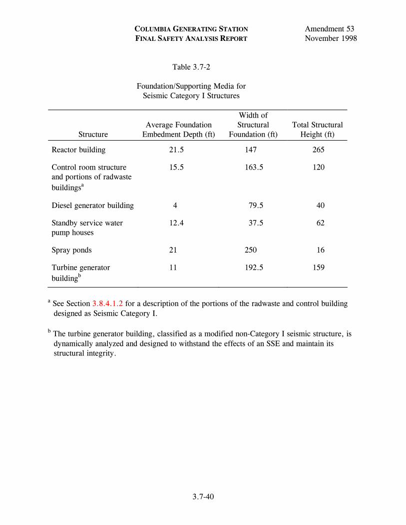
COLUMBIA GENERATING STATION Amendment 53 FINAL SAFETY ANALYSIS REPORT November 1998
3.7-40
Table 3.7-2 Foundation/Supporting Media for Seismic Category I Structures
Structure
Average Foundation
Embedment Depth (ft)
Width of Structural
Foundation (ft)
Total Structural
Height (ft)
Reactor building 21.5 147 265
Control room structure and portions of radwaste buildingsa
15.5 163.5 120
Diesel generator building 4 79.5 40
Standby service water pump houses
12.4 37.5 62
Spray ponds 21 250 16
Turbine generator buildingb
11 192.5 159
a See Section 3.8.4.1.2 for a description of the portions of the radwaste and control building
designed as Seismic Category I. b The turbine generator building, classified as a modified non-Category I seismic structure, is
dynamically analyzed and designed to withstand the effects of an SSE and maintain its structural integrity.

COLUMBIA GENERATING STATION Amendment 53 FINAL SAFETY ANALYSIS REPORT November 1998
3.7-41
Table 3.7-3 Reactor Building - Seismic Analysis Natural Frequency and Natural Period
Direction Mode Natural Frequency (cps) Natural Period (sec/cycle)
Horizontal (N-S) 1 1.92 0.519
2 3.42 0.292
3 5.17 0.193
4 5.88 0.170
5 7.52 0.133
6 10.37 0.096
7 11.41 0.087
8 12.54 0.079
9 16.82 0.059
10 18.80 0.053
Vertical 1 4.14 0.241
2 10.27 0.097
3 12.92 0.077
4 19.29 0.051
5 20.31 0.049
6 23.37 0.042
7 33.01 0.030
8 37.89 0.026
9 46.03 0.021
10 49.22 0.020

COLUMBIA GENERATING STATION Amendment 53 FINAL SAFETY ANALYSIS REPORT November 1998
3.7-42
Table 3.7-4 Reactor Building - Seismic Analysis Horizontal N-S Direction - OBE Acceleration (units in g x 10-3) Mode Numbers
Mass 1 2 3 4 5 6 7 8 9 10 Combined
1 681.65 770.36 147.14 10.00 0.58 1.13 0.61 1.74 0.02 0.05 1039.16 2 381.23 31.44 125.22 20.83 0.27 8.00 3.57 7.52 0.04 1.17 403.27 3 311.30 33.80 48.44 17.61 1.47 2.66 0.82 9.37 0.28 0.80 317.52 4 271.37 33.00 7.52 19.32 1.55 0.72 2.53 13.08 0.05 0.52 274.60 5 221.50 30.71 40.51 20.00 1.67 3.67 3.50 12.55 0.25 1.65 228.73 6 183.68 28.22 73.45 19.74 1.83 4.47 3.37 9.64 0.34 1.69 201.27 7 129.38 23.39 113.05 17.94 1.75 4.11 1.77 0.10 0.34 0.82 174.39 8 85.95 18.88 138.24 16.06 1.90 1.99 0.02 6.50 0.17 0.11 164.81 9 72.55 17.31 143.54 16.33 2.32 1.07 0.36 8.04 0.16 0.32 162.82
10 47.00 14.54 154.99 16.79 3.42 1.28 0.77 7.82 0.26 0.36 163.74 11 341.16 42.95 28.76 93.74 18.49 2.62 4.47 1.25 3.50 0.70 358.11 12 313.88 40.95 0.74 90.19 11.74 1.76 1.99 2.85 2.88 0.37 329.40 13 292.73 40.55 31.89 97.67 0.48 0.58 1.92 6.33 3.41 0.16 313.00 14 260.70 39.43 75.68 104.35 15.19 3.20 6.65 10.40 3.87 0.11 294.42 15 241.40 38.53 99.51 106.24 22.43 4.37 8.90 12.19 3.91 0.25 286.24 16 224.77 37.64 118.86 106.90 27.87 5.17 10.56 13.45 3.86 0.35 280.87 17 208.53 36.66 136.32 106.43 32.23 5.71 11.84 14.32 3.71 0.43 276.60 18 186.76 35.14 157.25 103.90 36.49 6.04 12.94 14.93 3.32 0.50 271.64 19 173.59 33.14 156.95 88.30 32.21 5.92 11.62 11.87 3.02 0.44 255.53 20 149.95 29.38 154.29 58.35 23.39 5.54 8.83 5.97 2.39 0.30 226.63 21 127.28 25.76 151.35 30.11 14.54 4.90 5.98 0.42 1.73 0.15 202.37 22 105.96 22.43 149.21 5.25 6.29 4.01 3.34 4.29 1.11 0.02 184.76 23 85.96 18.89 138.31 16.02 1.89 1.99 0.01 6.49 0.17 0.11 164.87 24 335.59 54.35 52.65 306.06 67.38 6.67 14.08 22.48 5.22 0.64 466.87 25 315.53 53.71 96.44 303.01 18.08 11.29 18.00 23.07 0.51 0.04 453.55 26 280.67 51.17 151.19 278.75 38.20 10.97 11.67 8.09 8.49 1.05 428.95 27 256.78 47.92 167.09 240.87 52.47 5.69 1.24 6.58 8.70 0.92 396.35 28 229.46 43.19 168.96 186.09 50.12 2.14 11.20 20.54 4.75 0.27 348.20 29 214.61 40.41 166.36 158.04 46.70 3.63 12.24 19.28 1.84 0.03 321.78 30 186.92 35.25 158.31 105.27 37.09 6.05 13.10 15.13 3.32 0.51 273.03 31 167.90 32.05 155.85 76.90 31.52 6.80 12.65 11.50 5.40 0.64 247.13 32 140.09 27.37 150.40 39.33 21.61 6.73 10.20 4.74 6.26 0.55 212.88 33 114.61 23.24 145.32 10.61 11.72 5.55 6.73 1.69 5.07 0.25 187.53 34 91.85 19.81 142.38 8.37 3.22 3.53 3.11 6.45 2.56 0.10 171.15 35 72.56 17.32 143.55 16.33 2.31 1.07 0.37 8.04 0.16 0.32 162.84

COLUMBIA GENERATING STATION Amendment 53 FINAL SAFETY ANALYSIS REPORT November 1998
3.7-43
Table 3.7-5 Reactor Building - Seismic Analysis Horizontal N-S Direction - OBE Displacement (units in ft x 10-4)
Mode Numbers
Mass 1 2 3 4 5 6 7 8 9 10 Combined
1 1502.05 -536.45 44.83 -2.36 0.08 -0.09 -0.04 -0.09 0.0 0.0 1595.60 2 840.07 21.90 -38.15 4.91 -0.04 0.61 0.22 0.39 0.0 0.03 841.24 3 685.97 23.54 -14.76 4.15 0.21 0.20 -0.05 -0.49 -0.01 0.02 686.54 4 597.97 22.98 -2.29 4.56 0.22 -0.05 -0.16 -0.68 0.0 -0.01 598.44 5 488.09 21.39 12.34 4.72 0.24 -0.28 -0.22 -0.65 0.01 -0.04 488.74 6 404.75 19.65 22.38 4.65 0.26 -0.34 -0.21 -0.50 0.01 -0.04 405.87 7 285.11 16.29 34.44 4.23 0.25 -0.31 -0.11 -0.01 0.01 -0.02 287.68 8 189.39 13.15 42.12 3.79 0.27 -0.15 0.0 0.34 0.0 0.0 194.50 9 159.88 12.06 43.73 3.85 0.34 -0.08 0.02 0.42 0.0 0.01 166.24
10 103.58 10.12 47.22 3.96 0.49 0.10 0.05 0.41 0.01 0.01 114.36 11 751.76 29.91 -8.76 -22.11 2.67 0.20 -0.28 -0.06 -0.01 0.02 752.74 12 691.65 28.51 -0.22 -21.27 1.70 0.13 -0.12 -0.15 -0.08 0.01 692.57 13 645.04 28.24 9.72 -23.03 -0.07 -0.04 0.12 -0.33 -0.10 0.0 646.14 14 574.46 27.46 23.06 -24.61 -2.19 -0.24 0.42 -0.54 -0.11 0.0 576.11 15 531.94 26.83 30.32 -25.05 -3.24 -0.33 0.56 -0.63 -0.11 -0.01 534.08 16 495.28 26.21 36.22 -25.21 -4.02 -0.39 0.66 -0.70 -0.11 -0.01 497.95 17 459.51 25.53 41.54 -25.10 -4.65 -0.43 0.74 -0.74 -0.11 -0.01 462.80 18 411.53 24.47 47.91 -24.50 -5.27 -0.46 0.81 -0.77 -0.10 -0.01 415.79 19 382.52 23.08 47.82 -20.82 -4.65 -0.45 0.73 -0.62 -0.09 -0.01 386.78 20 330.42 20.46 47.01 -13.76 -3.38 -0.42 0.55 -0.31 -0.07 -0.01 334.68 21 280.47 17.94 46.11 -7.10 -2.10 -0.37 0.37 -0.02 -0.05 0.0 284.90 22 233.48 15.62 45.46 -1.24 -0.91 -0.30 0.21 0.22 -0.03 0.0 238.38 23 189.42 13.15 42.14 3.78 0.27 -0.15 0.0 0.34 0.0 0.0 194.53 24 739.49 37.84 16.04 -72.17 9.73 0.15 -0.88 1.17 -0.15 -0.01 744.21 25 695.29 37.40 29.38 -71.45 2.61 0.86 -1.13 1.20 -0.01 0.0 700.58 26 618.47 35.64 46.06 -65.73 -5.52 0.83 -0.73 0.42 0.24 0.02 624.70 27 565.83 33.37 50.91 -56.80 -7.58 0.43 -0.08 -0.34 0.25 0.02 571.97 28 505.62 30.08 51.48 -43.88 -7.24 -0.16 0.70 -1.07 0.14 0.01 511.07 29 472.90 28.18 50.69 -37.27 -6.74 -0.28 0.76 -1.00 0.05 0.0 477.95 30 411.88 24.55 48.23 -24.82 -5.36 -0.46 0.82 -0.79 -0.10 -0.01 416.20 31 369.98 22.32 47.48 -18.13 -4.55 -0.52 0.79 -0.60 -016 -0.01 374.15 32 308.70 19.06 45.83 -9.27 -3.12 -0.51 0.64 -0.25 -0.18 -0.01 312.82 33 252.55 16.18 44.28 -2.50 -1.69 -0.42 0.42 0.09 -0.15 -0.01 256.93 34 202.40 13.80 43.38 1.97 -0.46 -0.27 0.19 0.33 -0.07 0.0 207.47 35 159.89 12.06 43.74 3.85 0.33 -0.08 0.02 0.42 0.00 0.01 166.25

COLUMBIA GENERATING STATION Amendment 53 FINAL SAFETY ANALYSIS REPORT November 1998
3.7-44
Table 3.7-6 Reactor Building - Seismic Analysis Horizontal N-S Direction - OBE Member Shears (units in kips) Mode Number
Member 1 2 3 4 5 6 7 8 9 10 Combined
1 1778.0 -2009.4 383.8 -26.1 -1.6 -2.9 -1.6 -4.5 0.0 0.1 2710.5 2 11509.0 -1207.3 -2810.3 505.3 -5.3 201.2 89.4 187.1 1.0 30.0 11924.0 3 20658.0 27.1 -3380.6 -400.9 117.5 272.8 62.0 -60.0 -11.2 52.1 20939.0 4 25430.0 607.2 -3512.9 -61.1 144.7 260.3 17.6 -290.1 -12.0 43.0 25682.0 5 29256.0 1137.6 -2814.5 284.1 173.5 196.9 -42.9 -506.6 -7.8 14.6 29421.0 6 32468.0 1631.7 -1527.9 628.9 205.5 118.6 -102.0 -675.6 -1.8 -15.0 32461.0 7 35151.0 2116.5 821.4 1002.5 241.7 33.2 -138.8 -673.5 5.2 -32.0 35248.0 8 39200.0 2760.0 4264.8 126.2 15.3 -9.3 -88.7 -622.9 -1.0 -31.5 39535.0 9 42109.0 3325.2 8593.9 419.2 -52.9 -58.7 -39.8 -441.4 -17.4 -25.0 43110.0 10 45884.0 4484.0 20920.0 1753.8 218.5 43.1 21.4 179.6 3.3 3.7 50658.0 11 72.0 9.0 -6.0 -19.6 3.9 0.5 -0.9 -0.3 -0.7 0.1 75.5 12 915.4 -42.7 -429.3 183.7 110.9 13.3 -14.9 11.4 1.5 0.2 1034.9 13 935.0 -39.8 -426.9 176.7 110.9 13.2 -14.7 11.0 1.2 0.2 1049.9 14 987.4 -32.2 -412.6 156.9 108.0 12.6 -13.5 9.0 0.5 0.2 1087.7 15 1003.5 -29.3 -405.0 148.7 106.3 12.3 -12.8 8.1 0.2 0.2 1098.1 16 1031.5 -24.7 -390.3 135.3 102.8 11.6 -11.5 6.4 -0.3 0.1 1116.4 17 1081.3 -16.0 -358.0 110.5 95.2 10.3 -8.7 3.0 -1.2 0.0 1148.6 18 2357.1 264.8 796.3 -1041.1 -211.3 6.1 30.4 -55.0 -2.1 -0.7 2719.6 19 2380.2 269.2 817.5 -1053.1 -215.8 5.3 32.0 -56.6 -2.6 -0.8 2751.3 20 2405.4 274.5 845.6 -1063.7 -220.1 4.2 33.6 -57.7 -3.0 -0.8 2786.6 21 2428.1 279.0 872.7 -1069.2 -222.7 3.4 34.7 -57.8 -3.3 -0.9 2817.2 22 2925.0 384.6 1574.3 -1093.9 -252.3 -15.5 50.4 -37.6 -8.5 -1.0 3528.4 23 241.7 -76.2 -242.9 390.3 -11.7 8.7 -19.1 28.1 -12.1 -1.1 527.4 24 56.8 -44.7 -186.4 212.8 -1.1 15.3 -29.7 41.6 -12.4 -1.2 301.2 25 236.4 -8.9 -28.2 -79.0 -41.1 26.8 -41.9 50.1 -3.5 -0.1 271.8 26 374.8 34.4 60.7 -207.0 -69.0 29.9 -42.5 46.6 1.1 0.4 449.2 27 817.9 120.1 395.4 -575.8 -168.3 25.6 -20.4 5.9 10.5 1.0 1095.9 28 1033.6 157.7 550.6 -723.2 -211.9 22.2 -8.9 -12.1 12.3 1.0 1401.9 29 493.9 17.7 28.4 8.3 -53.1 2.3 4.2 -14.4 0.0 -0.3 498.3 30 718.0 59.1 228.5 -90.4 -93.7 -6.5 20.5 -29.2 -7.0 -1.1 768.6 31 833.8 81.8 354.2 -123.3 -111.7 -12.1 29.0 -33.2 -12.2 -1.6 926.9 32 940.1 103.3 488.4 -133.1 -122.5 -17.2 35.2 -31.6 -16.8 -1.8 1082.0 33 1075.2 132.0 693.5 -121.1 -127.1 -22.3 39.7 -22.3 -20.5 -1.7 1300.0 34 314.3 -275.1 -803.8 1405.7 -82.4 3.8 4.1 -18.7 4.1 0.6 1674.4 35 -1119.5 -218.3 -380.7 1191.1 -188.0 -8.7 17.7 -30.8 1.6 0.5 1703.6 36 -3776.0 -415.0 1859.0 1043.3 247.6 22.8 -50.5 15.5 8.0 0.7 4362.9 37 -995.0 -151.0 -450.0 119.2 127.0 23.2 -40.4 12.0 20.4 1.3 1117.7 38 -1225.0 -275.8 -1122.2 1132.0 300.4 2.9 -36.5 54.8 0.3 0.7 2053.3

COLUMBIA GENERATING STATION Amendment 53 FINAL SAFETY ANALYSIS REPORT November 1998
3.7-45
Table 3.7-7 Reactor Building - Seismic Analysis Horizontal N-S Direction - OBE Member Moments (units in ft-kips x 103) Mode Number
1 2 3 4
Member Top Bottom Top Bottom Top Bottom Top Bottom
1 8.51 -92.52 -0.03 94.97 -9.02 -9.11 -0.1 1.25 2 146.58 -589.63 -95.16 141.64 -46.11 154.31 -1.32 -18.13 3 635.28 -1056.16 -140.82 140.27 -200.22 269.10 17.85 -9.68 4 1100.61 -1761.78 -138.92 123.13 -312.27 403.60 9.25 -7.66 5 1806.29 -2420.64 -121.11 97.22 -445.67 504.77 7.08 -13.05 6 2468.16 -3442.18 -94.44 45.49 -547.79 593.62 12.29 -31.19 7 3493.30 -4442.34 -41.67 -15.48 -638.79 616.56 29.85 -56.92 8 4690.34 -5032.50 33.19 -57.29 -615.24 578.02 3.70 -4.80 9 5157.28 -6000.32 68.62 -135.20 -583.26 411.20 -20.21 11.82 10 6382.04 6382.04 166.90 -166.90 -727.50 727.50 -27.03 27.03 11 0.03 -1.16 0.0 -0.14 -0.05 0.14 0.0 0.31 12 1.18 -10.19 0.15 0.27 -0.19 4.42 -0.31 -1.50 13 10.33 -25.52 -0.27 0.92 -4.46 11.39 1.49 -4.36 14 25.44 -35.56 -0.91 1.24 -11.52 15.75 4.35 -5.96 15 35.77 -44.90 -1.23 1.50 -15.80 19.48 5.94 -7.30 16 45.20 -54.66 -1.49 1.71 -19.57 23.14 7.27 -8.51 17 54.67 -68.45 -1.70 1.90 -23.35 27.91 8.45 -9.86 18 68.62 -85.18 -1.88 0.02 -28.12 22.52 9.78 -2.46 19 85.49 -115.57 0.0 -3.40 -22.62 12.28 2.40 10.91 20 115.86 -146.32 3.43 -6.90 -12.43 1.73 -10.99 24.46 21 146.30 -177.07 6.92 -10.46 -1.86 -9.20 -24.50 38.05 22 182.61 -217.71 10.93 -15.54 5.31 -24.20 -39.03 52.15 23 2.48 -0.09 0.24 0.51 -4.01 6.41 -3.03 -0.82 24 0.21 0.71 -0.50 1.22 -6.58 9.61 0.67 -4.13 25 -0.48 -1.94 -1.19 1.10 -9.81 10.10 3.82 -3.01 26 2.06 -6.36 -1.08 0.69 -10.14 9.45 2.83 -0.46 27 7.88 -13.45 -0.44 -0.38 -9.40 6.71 -2.03 5.95 28 13.52 -26.70 0.40 -2.41 -6.70 -0.32 -6.22 15.44 29 27.31 -31.90 2.51 -2.68 0.39 -0.66 -16.41 16.33 30 32.13 -42.32 2.71 -3.55 0.68 -3.92 -16.63 17.91 31 42.42 -54.16 3.57 -4.72 3.94 -8.93 -18.06 19.80 32 54.31 -67.56 4.74 -6.20 8.93 -15.81 -19.91 21.79 33 67.70 -82.82 6.22 -8.07 15.77 -25.52 -21.88 23.58 34 0.0 0.0 0.0 0.0 0.0 0.0 0.0 0.0 35 0.0 0.0 0.0 0.0 0.0 0.0 0.0 0.0 36 -214.67 214.67 -15.63 15.63 -19.68 19.68 52.36 52.36 37 -62.40 62.40 -7.84 7.84 -25.49 25.49 23.63 23.63 38 0.0 0.0 0.0 0.0 0.0 0.0 0.0 0.0

COLUMBIA GENERATING STATION Amendment 53 FINAL SAFETY ANALYSIS REPORT November 1998
3.7-46
Table 3.7-7 Reactor Building - Seismic Analysis Horizontal N-S Direction - OBE Member Moments (units in ft-kips x 103) (Continued) Mode Number
5 6 7 8
Member Top Bottom Top Bottom Top Bottom Top Bottom
1 -0.26 0.18 0.23 -0.09 0.43 -0.35 2.42 -2.21 2 -1.65 1.85 1.26 -9.00 2.40 -5.84 12.95 -20.15 3 -3.05 0.66 9.62 -15.18 7.23 -8.50 27.62 -26.40 4 -1.81 -1.96 15.34 -22.11 9.52 -9.98 32.32 -24.77 5 0.73 -4.38 21.48 -25.62 10.57 -9.67 29.30 -18.66 6 2.95 -9.12 24.05 27.61 9.89 -6.83 22.46 -2.20 7 7.18 -13.71 24.23 -25.12 6.52 -2.78 5.87 12.31 8 6.53 -6.66 23.10 -23.02 3.69 -2.91 -12.32 17.76 9 -0.67 1.72 19.21 -18.04 3.62 -2.82 -15.92 24.76 10 -20.57 20.57 -24.29 24.29 -2.54 2.54 15.97 -15.97 11 0.01 -0.07 0.0 -0.01 0.0 0.02 0.0 0.0 12 0.08 -1.18 0.01 -0.41 -0.02 0.17 0.0 -0.11 13 1.18 -2.98 0.14 -0.36 -0.17 0.41 0.12 -0.29 14 3.00 -4.11 0.36 -0.49 -0.42 0.56 0.30 -0.39 15 4.12 -5.09 0.49 -0.60 -0.56 0.67 0.40 -0.47 16 5.09 -6.04 0.60 -0.70 -0.68 0.78 0.47 -0.53 17 6.05 -7.26 0.70 -0.83 -0.79 0.90 0.53 -0.57 18 7.26 -5.78 0.82 -0.87 -0.90 0.69 0.57 -0.19 19 5.77 -3.04 0.8 -0.93 -0.69 0.28 0.19 0.53 20 3.03 -0.24 0.91 -0.97 -0.28 -0.14 -0.53 1.26 21 0.23 2.59 0.96 -1.00 0.15 -0.59 -1.26 1.99 22 -2.93 5.96 0.59 -0.41 0.59 -1.20 1.75 2.20 23 6.45 -6.33 -0.88 0.79 1.20 -1.01 -1.25 0.98 24 6.59 -6.57 -0.82 0.57 1.05 -0.57 -1.00 0.33 25 6.82 -6.40 -0.58 0.30 0.57 -0.14 -0.32 -0.19 26 6.46 -5.67 -0.30 -0.04 0.13 0.36 0.19 -0.73 27 5.53 -4.38 0.15 -0.33 -0.43 0.57 0.60 -0.64 28 4.36 -1.66 0.34 -0.62 -0.57 0.69 0.62 -0.47 29 1.51 -1.02 0.65 -0.67 -0.69 0.65 0.38 -0.24 30 0.96 0.37 0.67 -0.58 -0.64 0.35 0.21 0.21 31 -0.40 1.97 0.58 -0.41 -0.40 -0.07 -0.23 0.70 32 -2.01 3.74 0.41 -0.16 0.08 -0.58 -0.72 1.16 33 -3.77 5.56 0.15 0.16 0.59 -1.15 -1.17 1.49 34 0.0 0.0 0.0 0.0 0.0 0.0 0.0 0.0 35 0.0 0.0 0.0 0.0 0.0 0.0 0.0 0.0 36 6.11 -6.11 -0.09 0.09 -1.17 1.17 1.19 -1.90 37 5.57 -5.57 0.18 -0.18 -1.14 1.14 1.47 -1.47 38 0.0 0.0 0.0 0.0 0.0 0.0 0.0 0.0
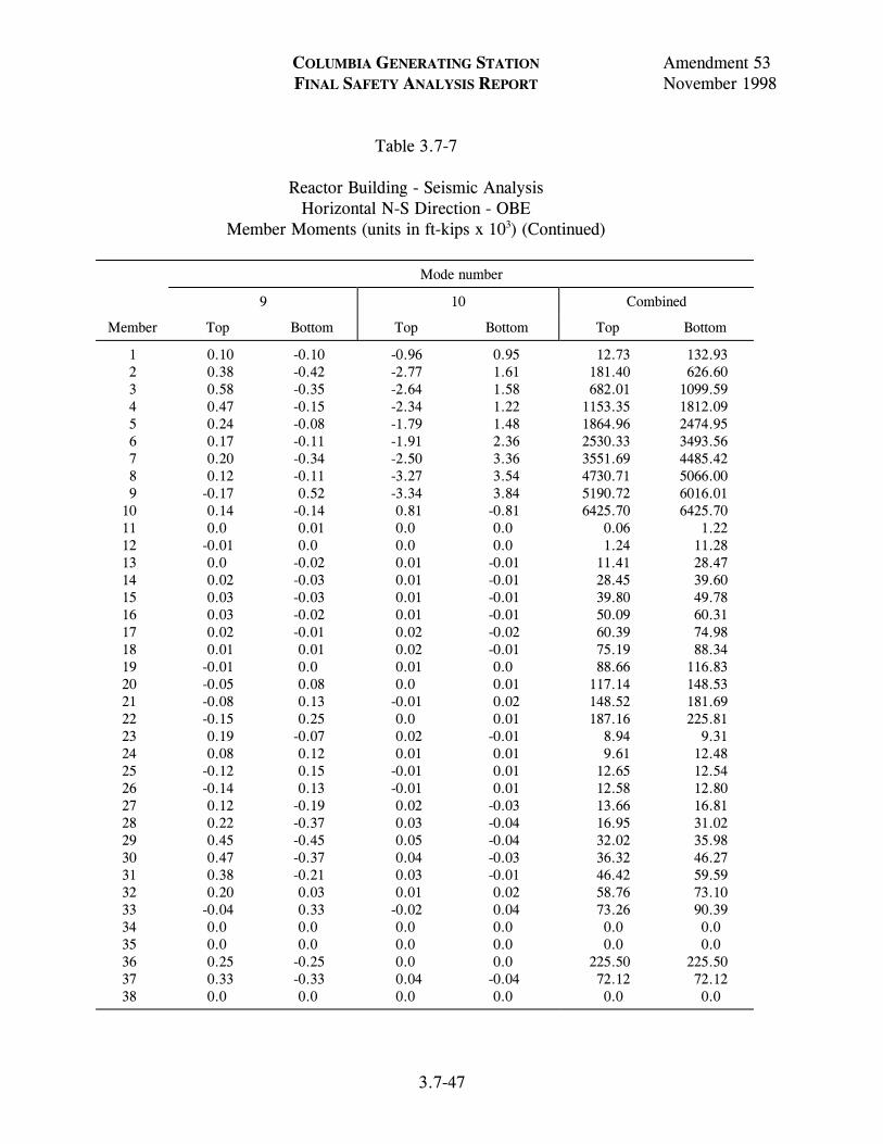
COLUMBIA GENERATING STATION Amendment 53 FINAL SAFETY ANALYSIS REPORT November 1998
3.7-47
Table 3.7-7 Reactor Building - Seismic Analysis Horizontal N-S Direction - OBE Member Moments (units in ft-kips x 103) (Continued)
Mode number
9 10 Combined
Member Top Bottom Top Bottom Top Bottom
1 0.10 -0.10 -0.96 0.95 12.73 132.93 2 0.38 -0.42 -2.77 1.61 181.40 626.60 3 0.58 -0.35 -2.64 1.58 682.01 1099.59 4 0.47 -0.15 -2.34 1.22 1153.35 1812.09 5 0.24 -0.08 -1.79 1.48 1864.96 2474.95 6 0.17 -0.11 -1.91 2.36 2530.33 3493.56 7 0.20 -0.34 -2.50 3.36 3551.69 4485.42 8 0.12 -0.11 -3.27 3.54 4730.71 5066.00 9 -0.17 0.52 -3.34 3.84 5190.72 6016.01 10 0.14 -0.14 0.81 -0.81 6425.70 6425.70 11 0.0 0.01 0.0 0.0 0.06 1.22 12 -0.01 0.0 0.0 0.0 1.24 11.28 13 0.0 -0.02 0.01 -0.01 11.41 28.47 14 0.02 -0.03 0.01 -0.01 28.45 39.60 15 0.03 -0.03 0.01 -0.01 39.80 49.78 16 0.03 -0.02 0.01 -0.01 50.09 60.31 17 0.02 -0.01 0.02 -0.02 60.39 74.98 18 0.01 0.01 0.02 -0.01 75.19 88.34 19 -0.01 0.0 0.01 0.0 88.66 116.83 20 -0.05 0.08 0.0 0.01 117.14 148.53 21 -0.08 0.13 -0.01 0.02 148.52 181.69 22 -0.15 0.25 0.0 0.01 187.16 225.81 23 0.19 -0.07 0.02 -0.01 8.94 9.31 24 0.08 0.12 0.01 0.01 9.61 12.48 25 -0.12 0.15 -0.01 0.01 12.65 12.54 26 -0.14 0.13 -0.01 0.01 12.58 12.80 27 0.12 -0.19 0.02 -0.03 13.66 16.81 28 0.22 -0.37 0.03 -0.04 16.95 31.02 29 0.45 -0.45 0.05 -0.04 32.02 35.98 30 0.47 -0.37 0.04 -0.03 36.32 46.27 31 0.38 -0.21 0.03 -0.01 46.42 59.59 32 0.20 0.03 0.01 0.02 58.76 73.10 33 -0.04 0.33 -0.02 0.04 73.26 90.39 34 0.0 0.0 0.0 0.0 0.0 0.0 35 0.0 0.0 0.0 0.0 0.0 0.0 36 0.25 -0.25 0.0 0.0 225.50 225.50 37 0.33 -0.33 0.04 -0.04 72.12 72.12 38 0.0 0.0 0.0 0.0 0.0 0.0

COLUMBIA GENERATING STATION Amendment 53 FINAL SAFETY ANALYSIS REPORT November 1998
3.7-48
Table 3.7-8 Reactor Building - Seismic Analysis Horizontal N-S Direction - SSE Acceleration (units in g x 10-3) Mode Number
Mass 1 2 3 4 5 6 7 8 9 10 Combine
1 1171.05 -1177.02 276.94 -15.31 0.87 -1.74 -0.92 -2.67 -0.03 0.07 1683.35 2 654.94 48.04 -235.69 31.90 -0.40 12.34 5.36 11.52 0.06 1.81 698.76 3 534.80 51.65 -91.18 26.96 2.15 4.10 -1.23 -14.37 -0.43 1.24 545.88 4 466.20 50.43 -14.14 29.59 2.33 -1.10 -3.80 -20.06 -0.07 -0.80 470.67 5 380.53 46.92 76.24 30.63 2.51 -5.66 -5.26 -19.23 0.37 -2.55 392.93 6 315.55 43.12 138.21 30.23 2.76 -6.89 -5.07 -14.78 0.52 -2.61 349.14 7 222.28 35.73 212.77 27.47 2.63 -6.34 -2.67 0.15 0.51 -1.26 311.07 8 147.65 28.85 260.19 24.60 2.87 -3.06 -0.03 9.96 0.25 0.16 301.76 9 124.64 26.45 270.16 25.01 3.51 -1.65 0.54 12.32 0.24 0.50 300.05 10 80.75 22.21 291.72 25.71 5.15 1.97 1.16 11.98 0.39 0.56 304.92 11 586.10 65.63 -54.12 -143.56 27.90 4.05 -6.72 1.91 -5.25 1.08 610.12 12 539.23 62.56 -1.39 -138.12 17.72 2.71 -2.99 -4.37 -4.32 0.57 560.50 13 502.89 61.95 60.02 -149.57 -0.73 -0.90 2.89 -9.70 -5.11 0.25 531.88 14 447.87 60.25 142.44 -159.81 -22.93 -4.93 9.99 -15.94 -5.81 -0.17 501.30 15 414.72 58.86 187.30 -162.70 -33.85 -6.73 13.38 -18.69 -5.87 -0.38 489.14 16 386.14 57.51 223.71 -163.71 -42.05 -7.97 15.87 -20.61 -5.79 -0.54 482.14 17 358.25 56.01 256.57 -162.99 -48.64 -8.81 17.79 -21.95 -5.57 -0.67 477.42 18 320.84 53.69 295.97 -159.12 -55.07 -9.31 19.44 -22.74 -4.98 -0.77 472.93 19 298.22 50.63 295.40 -135.23 -48.61 -9.13 17.46 -18.19 -4.53 -0.67 448.09 20 257.60 44.89 290.39 -89.37 -35.30 -8.55 13.26 -9.15 -3.59 -0.46 403.14 21 218.66 39.36 284.85 -46.11 -21.94 -7.56 8.99 -0.65 -2.60 -0.23 365.06 22 182.03 34.27 280.84 -8.04 -9.49 -6.18 5.01 6.57 -1.66 -0.04 336.91 23 147.68 28.86 260.31 24.53 2.85 -3.07 -0.02 9.95 0.25 0.16 301.86 24 576.53 83.03 99.10 -468.71 101.66 10.28 -21.16 34.47 -7.83 -1.00 763.14 25 542.07 82.06 181.51 -464.05 27.28 17.41 -27.05 35.37 -0.76 -0.07 744.18 26 482.18 78.19 284.55 -426.89 -57.65 16.91 -17.53 12.40 12.74 1.62 711.68 27 441.14 73.22 314.49 -368.87 -79.17 8.77 -1.87 -10.08 13.06 1.42 664.52 28 394.20 65.99 318.01 -284.98 -75.63 -3.30 16.83 -31.49 7.13 0.42 591.78 29 368.69 61.84 313.11 -242.03 -70.47 -5.60 18.40 -29.56 2.76 -0.04 551.07 30 321.12 53.86 297.95 -161.22 -55.96 -9.33 19.69 -23.20 -4.98 -0.78 475.25 31 288.45 48.96 293.32 -117.77 -47.57 -10.49 19.01 -17.62 -8.10 -0.99 435.07 32 240.68 41.82 283.08 -60.23 -32.60 -10.38 15.33 -7.27 -9.40 -0.85 381.06 33 196.89 35.51 273.50 -16.25 -17.68 -8.55 10.11 2.60 -7.60 -0.39 340.15 34 157.80 30.27 267.98 12.82 -4.86 -5.44 4.67 9.88 -3.85 0.15 313.17 35 124.65 26.46 270.19 25.01 -3.49 -1.66 0.55 12.32 0.23 0.50 300.07

COLUMBIA GENERATING STATION Amendment 53 FINAL SAFETY ANALYSIS REPORT November 1998
3.7-49
Table 3.7-9 Reactor Building - Seismic Analysis Horizontal N-S Direction - SSE Displacement (units in ft x 10-4)
Mode Number
Mass 1 2 3 4 5 6 7 8 9 10 Combined
1 2580.46 -819.63 84.38 -3.16 0.13 -0.13 -0.06 -0.14 0.0 0.0 2708.4 2 1443.20 33.46 -71.81 7.52 -0.06 0.94 0.36 0.60 0.0 0.04 1445.2 3 1178.46 35.97 -27.78 6.36 0.31 0.31 -0.08 -0.75 -0.01 0.03 1178.9 4 1027.29 35.11 -4.31 6.98 0.34 -0.08 -0.24 -1.04 0.0 -0.02 1027.6 5 838.50 32.67 23.23 7.22 0.36 -0.43 -0.33 -1.00 0.01 -0.06 839.5 6 695.34 30.03 42.11 7.13 0.40 -0.52 -0.32 -0.77 0.01 -0.06 697.3 7 489.79 24.88 64.83 6.48 0.38 -0.48 -0.17 0.01 0.01 -0.03 494.7 8 325.35 20.09 79.28 5.80 0.41 -0.23 0.0 0.52 0.01 0.0 335.6 9 274.66 18.42 82.31 5.90 0.50 -0.13 0.03 0.64 0.01 0.01 287.4 10 177.94 15.47 88.88 6.06 0.74 0.15 0.07 0.62 0.01 0.01 199.6 11 1291.49 45.70 -16.49 -33.85 4.03 0.31 -0.42 -0.10 -0.15 0.02 1292.4 12 1188.23 43.57 -0.42 -32.57 2.56 0.21 -0.19 -0.23 -0.12 0.01 1189.2 13 1108.15 43.14 18.29 -35.27 -0.11 -0.07 0.18 -0.50 -0.15 0.01 1109.6 14 986.90 41.95 43.40 -37.68 -3.11 -0.37 0.63 -0.83 -0.17 0.0 989.5 15 913.86 40.99 57.07 -38.36 -4.89 -0.51 0.84 -0.97 -0.17 -0.01 917.4 16 850.87 40.05 68.16 38.60 -6.07 -0.60 0.99 -1.07 -0.17 -0.01 855.4 17 789.41 39.01 78.17 -38.43 -7.02 -0.67 1.11 -1.14 -0.16 -0.02 795.2 18 706.99 37.39 90.18 -37.52 -7.95 -0.71 1.22 1.18 -0.14 -0.02 714.7 19 657.15 35.26 90.00 -31.89 -7.02 -0.69 1.09 -0.94 -0.13 -0.02 665.1 20 567.64 31.26 88.48 -21.07 -5.10 -0.65 0.83 -0.47 -0.10 -0.01 575.7 21 481.83 27.41 86.79 -10.87 -3.17 -0.57 0.56 -0.03 -0.07 -0.01 490.5 22 401.11 23.87 85.57 -1.90 -1.37 -0.47 0.31 0.34 -0.05 0.0 410.8 23 325.42 20.10 79.31 5.79 0.41 -0.23 0.0 0.52 0.01 0.0 335.6 24 1270.42 57.82 30.19 -110.52 14.68 0.78 -1.33 1.79 -0.23 -0.02 1276.6 25 1194.48 57.14 55.30 -109.42 3.94 1.32 -1.70 1.84 -0.02 0.0 1201.6 26 1062.51 54.45 86.70 -100.66 -8.32 1.28 -1.10 0.64 0.37 0.04 1072.7 27 972.08 50.98 95.82 -86.98 -11.43 0.67 -0.12 -0.52 0.38 0.03 982.1 28 868.64 45.95 96.89 -67.20 -10.92 -0.25 1.06 -1.63 0.21 0.01 887.8 29 812.43 43.06 95.40 -57.07 -10.18 -0.42 1.15 -1.53 0.08 0.0 821.2 30 707.59 37.51 90.78 -38.02 -8.08 -0.71 1.23 -1.20 -0.14 -0.02 715.4 31 635.61 34.10 89.37 -27.77 -6.87 -0.80 1.19 -0.91 -0.23 -0.02 643.4 32 530.34 29.12 86.25 -14.20 -4.71 -0.79 0.96 -0.38 -0.27 -0.02 538.3 33 433.86 24.73 88.33 -3.83 -2.55 -0.65 0.63 0.13 -0.22 -0.01 442.5 34 347.72 21.08 81.65 3.02 -0.70 -0.41 0.29 0.51 -0.11 0.0 357.8 35 274.68 18.42 82.32 5.90 0.50 -0.13 0.03 0.64 0.01 0.01 287.4

C
OL
UM
BIA
GE
NE
RA
TIN
G S
TA
TIO
N A
mendm
ent 53
FIN
AL
SA
FE
TY
AN
AL
YSIS R
EP
OR
T
Novem
ber 1998
3.7-50
Table 3.7-10
Reactor Building - Seismic Analysis Horizontal N-S Direction - SSE Member Shears (units in kips)
Mode Number
Member 1 2 3 4 5 6 7 8 9 10 Combined
1 3054.5 -3070.1 722.4 -39.9 2.3 -4.5 -2.4 -7.0 -0.1 0.2 4390.8 2 19772. -1844.7 -5289.3 773.8 -7.9 310.1 134.3 286.9 1.4 46.4 20571. 3 35489. 41.4 -6362.8 -613.9 177.3 420.6 93.1 -92.0 -16.8 80.7 36064. 4 43688. 927.8 -6611.8 -93.6 218.3 401.2 26.4 -444.7 -18.1 66.6 44200. 5 50259. 1738.1 -5297.2 435.1 261.8 303.5 -64.4 -776.7 -11.7 22.5 50578. 6 55778. 2493.1 -2875.7 964.7 310.1 182.8 -153.2 -1035.7 -2.7 -23.2 55930. 7 60387. 3233.8 1545.9 1535.2 364.7 51.1 -208.6 -1032.6 7.9 -49.4 60527. 8 67346. 4217.0 8027.3 193.3 23.1 -14.3 -133.3 -954.9 -1.5 -48.7 67962. 9 72339. 5080.6 16175. 642.0 -79.8 -90.5 -59.8 -676.8 -26.1 -38.6 74305. 10 78827. 6851.0 39375. 2685.8 329.7 66.4 32.1 275.4 5.0 5.7 88422. 11 123.6 13.8 -11.3 -30.1 5.8 0.8 -1.4 -0.4 -1.1 0.2 128.6 12 1572.5 -65.2 -808.0 281.3 167.4 20.4 -22.3 17.5 2.2 0.3 1799.7 13 1606.2 -60.8 -803.6 270.6 167.3 20.4 -22.1 16.8 1.8 0.3 1825.5 14 1696.3 -49.2 -776.6 240.3 163.0 19.4 -20.2 13.8 0.7 0.3 1889.1 15 1724.0 -44.8 -762.2 227.7 160.4 18.9 -19.2 12.4 0.3 0.3 1906.3 16 1772.1 -37.7 -734.7 207.2 155.2 17.9 -17.2 9.8 -0.4 0.2 1936.4 17 1857.7 -24.4 -673.8 169.3 143.6 15.9 -13.0 4.6 -1.8 0.0 1988.8 18 4049.4 404.6 1498.8 -1594.4 -318.9 9.3 45.7 -84.4 -3.2 -1.1 4633.4 19 4089.0 411.3 1538.7 -1612.8 -325.6 8.1 48.1 -86.8 -3.8 -1.2 4688.5 20 4132.4 419.4 1591.6 -1620.1 -322.1 6.5 50.5 -88.5 -4.5 -1.3 4750.7 21 4171.5 426.2 1642.6 -1637.4 -336.0 5.2 52.1 -88.6 -5.0 -1.4 4805.7 22 5024.9 587.6 2962.9 -1675.2 -380.6 -23.9 75.7 -57.7 -12.8 -1.5 6111.0 23 -415.2 -116.5 -457.2 597.7 -17.6 13.5 -28.7 43.0 -18.1 -1.8 870.7 24 -97.5 -68.2 -350.8 325.8 -1.6 23.7 -44.6 63.8 -18.6 -1.8 506.0 25 406.2 13.6 -53.1 -121.0 -62.0 41.4 -62.9 76.8 -5.2 -0.1 455.7 26 643.9 52.5 114.3 -317.0 -104.1 46.0 -63.9 71.4 1.7 0.7 749.8 27 1404.6 183.5 744.2 -881.9 -253.9 39.5 -30.6 9.1 15.8 1.5 1845.5 28 1775.6 241.0 1036.4 -1107.5 -319.7 34.3 -13.4 -18.6 18.4 1.4 2370.0 29 848.5 27.1 53.5 12.7 -80.2 3.5 6.4 -22.1 0.0 -0.5 855.0 30 1233.3 90.2 430.0 -138.5 -141.4 -10.0 30.8 -44.8 -10.4 -1.8 1326.3 31 1432.4 125.1 666.6 -188.9 -168.5 -18.6 43.6 -50.8 -18.3 -2.5 1607.9 32 1615.0 157.9 919.1 -203.8 -184.8 -26.5 52.9 -48.4 -25.3 -2.8 1888.2 33 1847.1 201.7 1305.3 -185.5 -191.9 -34.3 59.7 -34.2 -30.8 -2.7 2288.7 34 -539.8 -420.3 -1512.9 2152.7 -124.3 5.8 6.1 -28.7 6.2 0.9 2721.7 35 -1923.2 -333.6 -716.4 1824.1 -283.7 -13.4 26.6 -47.1 2.4 0.8 2781.5 36 -6464.0 -635.0 -3498.0 1593.3 373.6 35.1 -75.9 23.8 12.0 1.0 7557.2 37 -1728.0 -231.0 -853.0 182.3 191.7 35.8 -60.6 18.4 30.6 2.0 1961.0 38 -2105.0 -421.4 -2112.1 1733.6 453.2 4.4 -54.8 83.9 0.4 1.0 3507.1

COLUMBIA GENERATING STATION Amendment 53 FINAL SAFETY ANALYSIS REPORT November 1998
3.7-51
Table 3.7-11 Reactor Building - Seismic Analysis Horizontal N-S Direction - OBE Member Moments (units in ft-kips x 103)
Mode Number
1 2 3 4
Member Top Bottom Top Bottom Top Bottom Top Bottom
1 14.62 158.94 -0.05 145.11 -16.98 -17.15 -0.02 1.91 2 251.79 -1012.98 -145.39 216.41 -86.79 290.43 -2.03 -27.76 3 1091.38 -1814.46 -215.15 214.31 -376.84 506.47 27.33 -14.83 4 1890.82 -3026.67 -212.25 188.13 -587.73 759.63 14.16 -11.73 5 3103.17 -4158.56 -185.04 148.54 -838.79 950.03 10.85 -19.68 6 4240.21 -5913.52 -144.29 69.50 -1031.02 1117.29 18.82 -47.76 7 6001.30 -7631.71 -63.67 -23.65 -1202.18 1160.43 45.71 -87.16 8 8057.97 -8645.82 50.72 -87.53 -1158.00 1087.92 5.67 -7.36 9 8860.00 -10308.3 104.85 -206.56 -1097.75 773.93 -30.96 18.10 10 10964.1 -10964.1 255.01 -255.01 -1369.25 -1369.25 -41.39 41.39 11 0.05 -2.00 0.0 -0.22 -0.09 0.27 0.0 0.48 12 2.02 -17.51 0.22 0.42 -0.36 8.32 -0.48 -2.29 13 17.74 -43.84 -0.41 1.40 -8.39 21.44 2.28 -6.68 14 43.71 -61.10 -1.39 1.89 -21.68 29.64 6.66 -9.12 15 61.45 -77.13 -1.88 2.29 -29.73 36.67 9.10 -11.17 16 77.66 -93.91 -2.27 2.62 -36.82 43.56 11.13 -13.03 17 93.92 -117.60 -2.59 2.91 -43.94 52.53 12.94 -15.10 18 117.88 -146.34 -2.88 0.03 -52.92 42.38 14.98 -3.78 19 146.87 -198.55 0.0 -5.20 -42.57 23.12 3.67 16.71 20 199.05 -251.37 5.24 -10.55 -23.40 3.25 -16.83 37.45 21 251.34 -304.20 10.58 -15.98 -3.50 -17.31 -37.53 58.27 22 313.71 -374.01 16.69 -23.74 9.99 -45.55 -59.76 79.87 23 4.26 -0.16 0.37 0.78 -7.56 12.06 -4.64 -1.26 24 0.37 1.22 -0.76 1.87 -12.39 18.09 1.03 -6.33 25 -0.82 -3.34 -1.82 1.68 -18.46 19.00 5.85 -4.61 26 3.54 -10.92 -1.66 1.06 -19.09 17.78 4.33 -0.70 27 13.54 -23.11 -0.68 -0.57 -17.70 12.63 -3.11 9.12 28 23.23 -45.87 0.61 -3.68 -12.61 -0.61 -9.53 23.65 29 46.91 -54.81 3.84 -4.09 0.74 -1.24 -25.12 25.01 30 55.21 -72.71 4.15 -5.43 1.28 -7.39 -25.46 27.42 31 72.88 -93.05 5.46 -7.22 7.42 -16.80 -27.65 30.31 32 93.30 -116.06 7.24 -9.47 16.80 -29.75 -30.49 33.36 33 116.31 -142.28 9.50 -12.33 29.67 -48.02 -33.51 36.12 34 0.0 0.0 0.0 0.0 0.0 0.0 0.0 0.0 35 0.0 0.0 0.0 0.0 0.0 0.0 0.0 0.0 36 -368.38 368.38 -23.88 23.88 -37.07 37.07 80.19 -80.19 37 -107.26 107.26 -11.98 11.98 -47.94 47.94 36.19 -36.19 38 0.0 0.0 0.0 0.0 0.0 0.0 0.0 0.0

COLUMBIA GENERATING STATION Amendment 53 FINAL SAFETY ANALYSIS REPORT November 1998
3.7-52
Table 3.7-11 Reactor Building - Seismic Analysis Horizontal N-S Direction - OBE Member Moments (units in ft-kips x 103) (Continued)
Mode Number
5 6 7 8
Member Top Bottom Top Bottom Top Bottom Top Bottom
1 -0.39 0.28 0.35 -0.14 0.64 -0.53 3.71 -3.38 2 -2.49 2.80 1.94 -13.88 3.61 -8.77 19.85 -30.89 3 -4.61 0.99 14.84 -23.41 10.87 -12.77 42.34 -40.47 4 -2.73 -2.95 23.65 -34.08 14.31 -15.00 49.54 -37.98 5 1.11 -6.60 33.12 -39.49 15.89 -14.53 44.92 -28.61 6 4.46 -13.76 37.08 -42.56 14.86 -10.26 34.44 -3.37 7 10.84 -20.69 37.34 -38.72 9.80 -4.17 9.00 18.88 8 9.85 -10.05 35.61 -35.49 5.54 -4.38 -18.89 27.22 9 -1.00 2.60 29.62 -27.80 5.44 -4.24 -24.41 37.96 10 -31.04 31.04 -37.44 37.44 -3.82 3.82 24.49 -24.49 11 0.02 -0.11 0.0 -0.02 -0.01 0.03 0.0 0.0 12 0.12 -1.77 0.02 -0.22 -0.03 0.25 0.0 -0.18 13 1.78 -4.50 0.22 -0.55 -0.26 0.62 0.18 -0.45 14 4.53 -6.20 0.55 -0.75 -0.63 0.83 0.46 -0.60 15 6.22 -7.67 0.75 -0.92 -0.84 1.01 0.61 -0.72 16 7.69 -9.11 0.92 -1.09 -1.02 1.18 0.72 -0.81 17 9.13 -10.96 1.08 -1.28 -1.19 1.35 0.82 -0.88 18 10.96 -8.72 1.27 -1.33 -1.35 1.03 0.88 -0.29 19 8.71 -4.59 1.32 -1.43 -1.03 0.42 0.29 0.81 20 4.60 -0.37 1.41 -1.49 -0.42 -0.22 -0.81 1.93 21 0.35 3.91 1.47 -1.54 0.22 -0.88 -1.93 3.05 22 -4.43 8.99 0.92 -0.63 0.89 -1.80 -2.69 3.38 23 9.73 -9.55 -1.36 1.23 1.81 -1.52 -1.92 1.50 24 9.94 -9.92 -1.27 0.88 1.58 -0.85 -1.54 0.51 25 10.29 -9.66 -0.89 0.47 0.85 -0.21 -0.50 -0.29 26 9.75 -8.55 -0.46 -0.07 0.19 0.54 0.30 -1.12 27 8.34 -6.61 0.23 -0.50 -0.64 0.85 0.92 -0.98 28 6.58 -2.51 0.52 -0.95 -0.86 1.03 0.96 -0.72 29 2.28 -1.54 1.00 -1.03 -1.03 0.97 0.58 -0.37 30 1.46 0.55 1.04 -0.90 -0.96 0.52 0.32 0.32 31 -0.61 2.98 0.90 -0.63 -0.51 -0.10 -0.35 1.07 32 -3.03 5.64 0.63 -0.25 0.12 -0.87 -1.10 1.78 33 -5.69 8.39 0.23 0.25 0.88 -1.72 -1.80 2.28 34 0.0 0.0 0.0 0.0 0.0 0.0 0.0 0.0 35 0.0 0.0 0.0 0.0 0.0 0.0 0.0 0.0 36 9.22 -9.22 -0.14 0.14 -1.75 1.75 2.91 -2.91 37 8.41 -8.41 0.28 -0.28 -1.72 1.72 2.25 -2.25 38 0.0 0.0 0.0 0.0 0.0 0.0 0.0 0.0

COLUMBIA GENERATING STATION Amendment 53 FINAL SAFETY ANALYSIS REPORT November 1998
3.7-53
Table 3.7-11 Reactor Building - Seismic Analysis Horizontal N-S Direction - OBE Member Moments (units in ft-kips x 103) (Continued)
Mode Number
9 10 Combined
Member Top Bottom Top Bottom Top Bottom
1 0.15 -0.15 -1.48 1.47 22.83 215.95 2 0.57 -0.62 -4.28 2.50 304.36 1076.96 3 0.87 -0.53 -4.09 2.45 1176.1 1896.69 4 0.70 -0.23 -3.63 1.89 1992.61 3126.87 5 0.37 -0.12 -2.76 2.29 3220.62 4268.73 6 0.25 -0.17 -2.96 3.66 4366.61 6018.91 7 0.30 -0.51 -3.87 5.21 6121.17 7720.12 8 0.19 -0.17 -5.06 5.48 8141.03 8714.58 9 -0.25 0.77 -5.17 5.94 8928.51 10339.5 10 0.22 -0.22 1.26 -1.26 11052.4 11052.4 11 0.0 0.02 0.0 0.0 0.10 2.09 12 -0.02 0.0 0.0 -0.01 2.12 19.61 13 0.0 -0.03 0.01 -0.01 19.84 49.50 14 0.03 -0.04 0.01 -0.02 49.49 68.84 15 0.04 -0.04 0.02 -0.02 69.19 86.56 16 0.04 -0.04 0.02 -0.02 87.06 104.79 17 0.03 -0.01 0.02 -0.02 104.95 130.21 18 0.01 0.01 0.03 -0.02 130.60 152.66 19 -0.02 0.07 0.02 0.0 153.21 200.72 20 -0.07 0.12 0.0 0.01 201.25 254.39 21 -0.13 0.19 -0.01 0.03 254.39 310.68 22 -0.22 0.38 0.0 0.02 320.00 386.02 23 0.29 -0.11 0.03 -0.01 14.40 15.80 24 0.11 0.19 0.01 0.02 16.29 21.76 25 -0.17 0.23 -0.02 0.02 22.08 22.14 26 -0.21 0.19 -0.02 0.01 22.23 22.65 27 0.18 -0.29 0.03 -0.04 24.06 28.71 28 0.33 -0.56 0.04 -0.06 28.93 51.84 29 0.68 -0.68 0.07 -0.07 53.44 60.44 30 0.71 -0.56 0.07 -0.04 60.99 78.26 31 0.57 -0.31 0.04 -0.01 78.51 99.61 32 0.31 0.05 0.01 0.03 99.90 124.89 33 -0.06 0.49 -0.03 0.07 125.15 155.22 34 0.0 0.0 0.0 0.0 0.0 0.0 35 0.0 0.0 0.0 0.0 0.0 0.0 36 0.37 -0.37 0.0 0.0 379.72 379.72 37 0.49 -0.49 0.07 -0.07 123.87 123.87 38 0.0 0.0 0.0 0.0 0.0 0.0

COLUMBIA GENERATING STATION Amendment 53 FINAL SAFETY ANALYSIS REPORT November 1998
3.7-54
Table 3.7-12 Reactor Building - Seismic Analysis Vertical Direction - OBE Acceleration (units in g x 10-3)
Mode Number
Mass 1 2 3 4 5 6 7 8 9 10 Combined
1 159.32 -0.14 -38.87 7.46 1.10 0.41 -0.53 -0.01 0.0 -0.06 164.22 2 151.73 -0.10 -20.81 -0.27 -0.16 -0.21 1.09 0.02 0.0 -0.33 153.15 3 149.49 -0.09 -17.58 -0.41 -0.15 -0.14 0.21 0.0 0.0 0.28 150.52 4 146.55 -0.08 -13.80 -0.42 -0.10 -0.05 -0.50 -0.02 0.0 0.30 147.20 5 142.40 -0.06 -8.79 -0.37 -0.04 0.06 -1.06 -0.02 0.0 0.04 142.68 6 138.52 -0.05 -4.54 -0.29 0.02 0.14 -1.15 -0.02 0.0 -0.19 138.60 7 131.84 -0.03 2.00 -0.12 0.09 0.21 -0.76 0.0 0.0 -0.32 131.85 8 126.72 -0.01 6.16 0.0 0.13 0.23 -0.23 0.01 0.0 -0.15 126.87 9 125.01 -0.01 7.41 0.04 0.14 0.22 -0.05 0.02 0.0 -0.08 125.23 10 122.55 0.0 8.78 0.08 0.14 0.20 0.19 0.02 0.0 0.04 122.86 11 129.23 0.0 15.72 0.45 1.12 -11.97 -1.27 2.68 0.0 0.06 130.77 12 129.00 0.0 15.46 0.43 1.07 -11.30 -1.13 2.29 0.0 0.05 130.45 13 128.80 0.0 15.22 0.42 1.03 -10.72 -1.01 1.96 0.0 0.04 130.17 14 128.53 0.0 14.90 0.40 0.98 -9.93 -0.84 1.52 0.0 0.02 129.79 15 128.31 0.0 14.65 0.38 0.93 -9.35 -0.73 1.23 0.0 0.01 129.50 16 128.11 0.0 14.42 0.37 0.90 -8.81 -0.63 0.96 0.0 0.0 129.23 17 127.90 0.0 14.17 0.35 0.86 -8.26 -0.53 0.70 0.0 -0.01 128.96 18 127.57 0.0 13.80 0.33 0.79 -7.44 -0.39 0.36 0.0 -0.02 128.54 19 127.38 0.0 13.59 0.32 0.76 -6.99 -0.31 0.19 0.0 -0.02 128.30 20 126.97 0.0 13.14 0.29 0.69 -6.06 -0.16 -0.15 0.0 -0.03 127.80 21 126.54 0.0 12.67 0.26 0.62 -5.09 -0.02 -0.46 0.0 -0.03 127.28 22 126.10 0.0 12.19 0.24 0.55 -4.16 0.11 -0.73 0.0 -0.03 126.76 23 124.57 0.0 10.70 0.17 0.36 -2.13 0.17 -0.43 0.0 0.01 125.05 24 156.00 1.22 -31.69 0.64 4.86 0.29 0.06 -0.01 -0.09 -0.03 159.28 25 153.67 1.10 -27.09 -0.43 3.12 0.15 0.03 0.0 0.07 0.03 156.09 26 149.00 0.88 -18.05 -0.39 -0.17 -0.10 -0.09 -0.01 0.29 0.11 150.09 27 145.12 0.71 -11.26 0.21 -2.22 -0.24 -0.12 -0.01 0.21 0.06 145.58 28 140.28 0.50 -3.28 0.48 -4.33 -0.37 -0.12 -0.01 0.02 -0.02 140.40 29 139.66 0.47 -2.50 0.49 -4.40 -0.37 -0.11 -0.01 0.0 -0.02 139.77 30 138.19 0.43 -0.83 0.50 -4.41 -0.35 -0.08 0.0 -0.04 -0.03 138.28 31 136.62 0.38 0.42 0.47 -4.05 -0.29 -0.04 0.0 -0.06 -0.02 136.69 32 133.97 0.30 2.32 0.41 -3.30 -0.20 0.02 0.01 -0.06 0.01 134.04 33 131.18 0.22 4.17 0.33 -2.47 -0.09 0.08 0.01 -0.06 0.03 131.29 34 128.22 0.14 5.98 0.25 -1.57 -0.02 0.14 0.01 -0.04 0.04 128.38 35 125.01 0.06 7.66 0.15 -0.58 0.13 0.17 0.02 -0.02 0.05 125.24

COLUMBIA GENERATING STATION Amendment 53 FINAL SAFETY ANALYSIS REPORT November 1998
3.7-55
Table 3.7-13 Reactor Building - Seismic Analysis Vertical Direction - OBE Displacement (units in ft x 10-6)
Mode Number
Mass 1 2 3 4 5 6 7 8 9 10 Combined
1 7589.63 -1.03 -190.01 16.34 0.18 0.61 -0.40 0.0 0.0 0.02 7692.03 2 7227.78 -0.76 -101.69 -0.59 -0.32 -0.32 0.81 0.01 0.0 -0.11 7228.50 3 7121.02 -0.69 -85.94 -0.91 -0.29 -0.21 0.16 0.0 0.0 0.09 7121.54 4 6981.40 -0.60 -67.43 -0.92 -0.20 -0.07 -0.37 -0.01 0.0 0.10 6981.73 5 6783.59 -0.48 -42.96 -0.80 -0.07 0.09 -0.79 -0.01 0.0 0.01 6783.73 6 6598.67 -0.37 -22.17 -0.63 0.04 0.20 -0.86 -0.01 0.0 -0.06 6598.71 7 6280.28 -0.20 9.78 -0.27 0.18 0.32 -0.57 0.0 0.0 -0.11 6280.29 8 6036.62 -0.08 30.11 0.0 0.26 0.34 -0.17 0.01 0.0 -0.05 6036.70 9 5955.15 -0.04 36.20 0.08 0.28 0.33 -0.03 0.01 0.0 -0.03 5955.26 10 5837.88 0.01 42.90 0.18 0.28 0.30 0.14 0.01 0.0 0.01 5838.04 11 6256.11 0.01 76.86 0.98 2.22 -17.68 -0.95 1.53 0.0 0.02 6156.62 12 6145.35 0.01 75.55 0.94 2.13 -16.88 -0.84 1.30 0.0 0.02 6145.84 13 6135.73 0.01 74.39 0.91 2.04 -16.01 -0.75 1.11 0.0 0.01 6136.20 14 6122.58 0.01 72.81 0.87 1.93 -14.84 -0.63 0.87 0.0 0.01 6123.03 15 6112.33 0.01 71.59 0.83 1.85 -13.96 -0.55 0.70 0.0 0.0 6112.77 16 6102.83 0.01 70.47 0.80 1.77 -13.17 -0.47 0.55 0.0 0.0 6103.25 17 6092.76 0.01 69.28 0.77 1.69 -12.34 -0.40 0.40 0.0 0.0 6093.17 18 6077.03 0.01 67.46 0.72 1.57 -11.12 -0.29 0.20 0.0 -0.01 6077.42 19 6067.97 0.01 66.42 0.69 1.51 -10.44 -0.23 0.11 0.0 -0.01 6068.34 20 6048.69 0.01 64.23 0.64 1.37 -9.05 -0.12 -0.09 0.0 -0.01 6049.04 21 6028.00 0.01 61.90 0.58 1.22 -7.61 -0.02 -0.26 0.0 -0.01 6028.32 22 6007.02 0.01 59.58 0.52 1.08 -6.22 0.08 -0.42 0.0 -0.01 6007.32 23 5934.34 0.01 52.28 0.37 0.72 -3.19 0.13 -0.24 0.0 0.0 5934.57 24 7431.29 9.41 -154.90 -1.40 9.61 0.43 0.04 0.0 -0.03 -0.01 7432.91 25 7320.58 8.54 -132.40 -0.94 6.16 0.23 0.0 0.0 0.03 0.01 7321.78 26 7097.74 6.83 -88.21 -0.09 -0.35 -0.15 -0.07 -0.01 0.11 0.04 7098.29 27 6913.16 5.49 -55.01 0.47 -4.40 -0.36 -0.09 -0.01 0.08 0.02 6913.38 28 6682.37 3.87 -16.01 1.05 -8.56 -0.55 -0.09 -0.01 0.01 -0.01 6682.40 29 6653.12 3.69 -12.22 1.08 -8.69 -0.55 -0.08 0.0 0.0 -0.01 6653.14 30 6582.74 3.29 -4.05 1.10 -8.72 -0.52 -0.06 0.0 -0.02 -0.01 6582.75 31 6508.01 2.12 2.06 1.04 -8.00 -0.44 -0.03 0.0 -0.02 -0.01 6508.02 32 6381.94 2.33 11.33 0.90 -6.53 -0.29 0.02 0.0 -0.02 0.0 6381.95 33 6249.23 1.72 20.40 0.73 -4.89 -0.13 0.06 0.01 -0.02 0.01 6249.27 34 6108.22 1.01 29.41 0.55 -3.10 0.03 0.10 0.01 -0.02 0.01 6108.29 35 5954.94 0.46 37.42 0.34 -1.15 0.19 0.13 0.01 -0.01 0.02 5955.06

COLUMBIA GENERATING STATION Amendment 53 FINAL SAFETY ANALYSIS REPORT November 1998
3.7-56
Table 3.7-14
Reactor Building - Seismic Analysis Vertical Direction - SSE Acceleration (units in g x 10-3)
Mode Number
Mass 1 2 3 4 5 6 7 8 9 10 Combined
1 313.63 -0.21 -60.27 11.68 1.78 0.72 -1.07 -0.02 0.0 0.12 319.65 2 298.67 -0.15 -32.26 -0.42 -0.27 -0.38 2.18 0.05 0.0 -0.66 300.42 3 294.26 -0.13 -27.26 -0.65 -0.24 -0.25 0.42 0.0 0.0 0.57 295.52 4 288.49 -0.12 -21.39 -0.66 -0.16 -0.09 -0.99 -0.04 0.0 0.59 289.29 5 280.32 -0.09 -13.63 -0.57 -0.06 0.11 -2.2 -0.05 0.0 0.07 280.66 6 272.68 -0.07 -7.03 -0.45 0.03 0.24 -2.31 -0.04 0.0 -0.38 272.78 7 259.52 -0.04 3.10 -0.19 0.15 0.37 -1.52 0.0 0.0 -0.64 259.54 8 249.45 -0.02 9.55 0.0 0.21 0.39 -0.45 0.02 0.0 -0.30 249.64 9 246.08 -0.01 11.48 0.06 0.23 0.39 -0.09 0.03 0.0 0.15 246.35 10 241.24 0.0 13.61 0.13 0.23 0.35 0.37 0.03 0.0 0.08 241.62 11 254.39 0.0 24.38 0.70 1.81 -20.94 -2.54 5.38 0.0 0.13 256.49 12 253.94 0.0 23.97 0.67 1.74 -19.78 -2.26 4.60 0.0 0.10 255.90 13 253.55 0.0 23.60 0.65 1.67 -18.76 -2.02 3.93 0.0 0.08 255.38 14 253.00 0.0 23.09 0.62 1.58 -17.38 -1.69 3.06 0.0 0.04 254.68 15 252.58 0.0 22.71 0.60 1.51 -16.36 -1.47 2.46 0.0 0.02 254.15 16 252.19 0.0 22.35 0.57 1.45 -15.42 -1.26 1.93 0.0 0.0 253.66 17 251.77 0.0 21.98 0.55 1.38 -14.46 -1.06 1.41 0.0 -0.01 253.15 18 251.12 0.0 21.40 0.52 1.28 -13.02 -0.78 0.72 0.0 -0.03 252.38 19 250.75 0.0 21.07 0.50 1.23 -12.24 -0.63 0.37 0.0 -0.04 251.93 20 249.95 0.0 20.37 0.46 1.12 -10.60 -0.33 -0.30 0.0 -0.05 251.01 21 249.10 0.0 19.64 0.41 1.00 -8.92 -0.04 -0.93 0.0 -0.06 250.03 22 248.23 0.0 18.90 0.37 0.88 -7.29 0.22 -1.47 0.0 -0.06 249.06 23 245.23 0.0 16.58 0.26 0.59 -3.73 0.34 -0.86 0.0 0.01 245.82 24 307.08 1.83 -49.13 -1.00 7.85 0.51 0.12 0.01 -0.18 -0.06 311.12 25 302.51 1.66 -42.00 -0.67 5.03 0.27 0.01 0.0 0.15 0.06 305.47 26 293.30 1.33 -27.98 -0.06 -0.28 -0.18 -0.18 -0.02 0.59 0.21 294.64 27 285.67 1.07 -17.45 0.33 -3.59 -0.42 -0.23 -0.02 0.41 0.12 286.23 28 276.14 0.75 -5.08 0.75 -6.99 -0.65 -0.23 -0.02 0.04 -0.04 276.30 29 274.93 0.72 -3.88 0.77 -7.10 -0.64 -0.21 -0.02 0.0 -0.05 275.07 30 272.02 0.64 -1.28 0.79 -7.12 -0.61 -0.16 -0.01 -0.09 -0.06 272.14 31 268.93 0.57 0.65 0.74 -6.53 -0.52 -0.08 0.0 -0.11 -0.03 269.03 32 263.72 0.45 3.59 0.64 -5.34 -0.34 0.04 0.01 -0.12 0.01 263.82 33 258.24 0.33 6.47 0.52 -4.00 -0.16 0.16 0.02 -0.11 0.05 258.37 34 252.41 0.21 9.27 0.39 -2.53 0.03 0.27 0.03 -0.09 0.09 252.60 35 246.08 0.09 11.87 0.24 -0.94 0.22 0.34 0.03 -0.04 0.09 246.37

COLUMBIA GENERATING STATION Amendment 53 FINAL SAFETY ANALYSIS REPORT November 1998
3.7-57
Table 3.7-15 Reactor Building - Seismic Analysis Vertical Direction - SSE Displacement (units in ft x 10-6)
Mode Number
Mass 1 2 3 4 5 6 7 8 9 10 Combined
1 14940.2 -1.62 -294.60 25.60 3.52 1.08 -0.80 -0.01 0.0 0.04 14943.1 2 14227.9 -1.14 -157.67 -0.93 -0.52 -0.56 1.63 0.03 0.0 -0.22 14228.8 3 14017.8 -1.04 -133.25 -1.42 -0.47 -0.37 0.32 0.0 0.0 0.19 14018.4 4 13742.9 -0.90 -104.55 -1.44 -0.33 -0.13 -0.74 -0.02 0.0 0.20 13743.3 5 13353.5 -0.72 -66.61 -1.26 -0.12 0.16 -1.59 -0.03 0.0 0.02 13353.7 6 12989.5 -0.56 -34.38 -0.98 0.06 0.36 -1.73 -0.02 0.0 -0.13 12989.5 7 12362.8 -0.30 15.16 -0.42 0.30 0.56 -1.14 0.0 0.0 -0.22 12362.8 8 11883.1 -0.12 46.69 -0.01 0.42 0.59 -0.34 0.01 0.0 -0.10 11883.2 9 11722.7 -0.06 56.13 0.12 0.45 0.58 -0.07 0.02 0.0 -0.05 11722.8 10 11491.9 0.01 66.52 0.28 0.46 0.52 0.28 0.02 0.0 0.03 11492.1 11 12118.3 0.01 119.16 1.54 3.58 -31.28 -1.90 3.06 0.0 0.04 12118.9 12 12097.2 0.01 117.14 1.48 3.43 -29.54 -1.69 2.61 0.0 0.03 12097.8 13 12078.2 0.01 115.35 1.43 3.30 -28.02 -1.51 2.23 0.0 0.02 12078.8 14 12052.3 0.01 112.88 1.36 3.12 -25.96 -1.27 1.74 0.0 0.01 12052.9 15 12032.1 0.01 111.00 1.30 2.98 -24.44 -1.10 1.40 0.0 0.01 12032.6 16 12013.4 0.01 109.26 1.26 2.86 -23.04 -0.95 1.09 0.0 0.0 12013.9 17 11993.6 0.01 107.41 1.21 2.73 -21.59 -0.79 0.80 0.0 0.0 11994.1 18 11962.7 0.01 104.59 1.13 2.54 -19.45 -0.58 0.41 0.0 -0.01 11963.2 19 11944.8 0.01 102.99 1.09 2.43 -18.28 -0.47 0.21 0.0 -0.01 11945.2 20 11906.9 0.01 99.59 1.00 2.20 -15.83 -0.25 -0.17 0.0 -0.02 11907.3 21 11866.1 0.01 95.98 0.91 1.97 -13.32 -0.03 -0.53 0.0 -0.02 11866.5 22 11824.8 0.01 92.38 0.81 1.74 -10.89 0.17 -0.83 0.0 -0.02 11825.2 23 11681.8 0.01 81.06 0.57 1.16 -5.57 0.25 -0.49 0.0 0.0 11682.1 24 14628.5 14.12 -240.17 -2.19 15.53 0.76 0.09 0.01 -0.07 -0.02 14640.5 25 14410.6 12.82 -205.28 -1.48 9.95 0.40 0.0 0.0 0.06 0.02 14412.1 26 13971.9 10.25 -136.77 -0.13 -0.56 -0.27 -0.14 -0.01 0.23 0.07 13972.6 27 13608.6 8.24 -85.30 0.73 -7.10 -0.63 -0.17 -0.01 0.16 0.04 13608.9 28 13154.3 5.81 -24.82 1.64 -13.82 -0.97 -0.17 -0.01 0.01 -0.01 13154.3 29 13096.7 5.54 -18.95 1.69 -14.04 -0.96 -0.16 -0.01 0.0 -0.02 13096.7 30 12958.1 4.94 -6.28 1.73 -14.09 -0.91 -0.12 -0.01 -0.03 -0.02 12958.1 31 12811.0 4.38 3.19 1.62 -12.91 -0.77 -0.06 0.0 -0.04 -0.01 12811.0 32 12562.9 3.49 17.57 1.40 -10.55 -0.51 0.03 0.01 -0.05 0.0 12562.9 33 12301.6 2.58 31.63 1.15 -7.90 -0.23 0.12 0.01 -0.04 0.02 12301.6 34 12024.0 1.65 45.29 0.86 -5.00 0.05 0.20 0.02 -0.03 0.03 12024.1 35 11722.3 0.70 58.02 0.53 -1.86 0.33 0.26 0.02 -0.02 0.03 11722.4

COLUMBIA GENERATING STATION Amendment 54 FINAL SAFETY ANALYSIS REPORT April 2000
LDCN-99-000 3.7-58
Table 3.7-16 Lumped Representation of Soil-Structure Interaction
Motion
Equivalent Spring Constanta
Equivalent Damping Coefficienta,b
A. For a Rectangular Foundation Vertical k G cdv v=
−14
νβ (c)
Horizontal
( )k G cdh h= +4 1 ν β (c)
Rocking k G cdr R=−
⋅1
8 2
νβ (c)
Torsional (c) (c) B. For a Circular Foundation
Vertical k GRv = −
41 ν
c k R Gv v= 0 85. ρ
Horizontal ( )k GR
h =−−
32 17 8
ν c k R Gh h= 0 575. ρ
Rocking
( )k GR
R =−
83 1
3
ν c
Bk R GR
RR=
+0 30
1. ρ
Torsional k GR
t = 163
3
ck I
Btt t
t
=+1 2
a In above formulas 2c = width of the rectangular foundation (along axis of rotation for the
case of rocking) 2d = length of the rectangular foundation (in the plane of rotation for rocking) βv, βh, and βR = constants depending on the ratio d/c (See Figure 10-16, p. 351 of
Reference 3.7-5) R = radius of the circular foundation
( )B
IRR
R=−3 1
8 5
νρ
IR = total mass moment of inertia of structure and foundation about the rocking axis at the base
B IRT
T= ρ 5
IT = polar mass moment of inertia of structure and foundation G = shear modulus of soil material ν = Poisson's ratio of soil material ρ = density of soil material

COLUMBIA GENERATING STATION Amendment 53 FINAL SAFETY ANALYSIS REPORT November 1998
3.7-59
Table 3.7-16 Lumped Representation of Soil-Structure Interaction (Continued) b Conservative values not exceeding those defined in Table 3.7-1 are used for the soil damping
in the analytical model for soil-structure interaction. c Use formulas and diagrams for an equivalent circular base with a radius determined by the
following:
For translation: R cd= 4π
For rocking: R cd= 163
34
π
For torsion: ( )
Rcd c d
=+16
6
2 2
4π

COLUMBIA GENERATING STATION Amendment 53 FINAL SAFETY ANALYSIS REPORT November 1998
3.7-60
Table 3.7-17 Dynamic Response Cycles Expected During a Seismic Event for Nuclear Steam Supply Systems and Components
Frequency Bandwidth (Hz)
Number of Seismic Cycles 0-10 10-20 20-50
Total 168 359 643
Between 75% and 100% of peak loads (0.5% of total)
0.8 1.8 3.2
Between 50% 75% of peak loads (4.5% of total) 7.5 16.2 28.9

COLUMBIA GENERATING STATION Amendment 53 FINAL SAFETY ANALYSIS REPORT November 1998
3.7-61
Table 3.7-18 Fatigue Evaluation Due to Seismic Load
Component
Calculated Number of Cycles at Peak Stress
Design Number of OBE Cycles at Peak Stress
1. Reactor pressure vessel
Vessel 3 10
Shroud support 3 10
Skirt 3 10
2. Category I piping
Recirculation lines 3 50
Steam lines 3 50

COLUMBIA GENERATING STATION Amendment 53 FINAL SAFETY ANALYSIS REPORT November 1998
3.7-62
Table 3.7-19 Comparison of the Maximum and Allowable Seismic Loads of Reactor Pressure Vessel and Internals
Seismic Loads
Location X-Excitation Y-Excitation Allowable Loads
Top guide shear (kip) 333 292 860
Core plate shear (kip) 333 290 860
Stabilizer force (total) (kip) 1250 1250 3600
Maximum fuel moment:
Total (in.-kip) 16,960 14,760 40,300
Per bundle (in.-kip) 22.2 19.3 52.7
Maximum shroud moment (in.-kip) 220,500 218,500 450,900
Maximum shroud shear (kip) 1030 1030 2386
Maximum vessel shirt moment (in.-kip) 204,900 170,700 2,304,000
Vessel skirt shear (kip) 1130 1100 5200

Amendment 53 November 1998
Columbia Generating Station Final Safety Analysis Report
Response Spectra Safe Shutdown Earthquake - Horizontal Component
Draw. No. 020552.08 Rev. Figure 3.7-1

Amendment 53 November 1998
Columbia Generating Station Final Safety Analysis Report
Response Spectra Safe Shutdown Earthquake - Vertical Component
Draw. No. 020552.09 Rev. Figure 3.7-2

0.06
0.1
0.2
0.60.8
2
4
68
.01
Amendment 55May 2001
Response Spectra Operating Basis Earthquake -Horizontal Component
990578.99 3.7-3FigureForm No. 960690
Draw. No. Rev.
10 8 6 5 4 3 2.5 2 1 0.8 0.6 0.5 0.4 0.3 0.25 0.2 0.1 .08 .06 .05 .04 .03 .025 .02
1
40
30
20
109876
5
4
3
2
10.90.80.70.6
0.5
0.4
0.3
0.2
0.1
40
30
20
109876
5
4
3
2
10.90.80.70.6
0.5
0.4
0.3
0.2
0.1
Velo
city
In/S
ec
0.1 0.2 0.3 0.4 .5 .6 .7 .8 1 2 3 4 5 6 7 8 9 20 30 40 50 60 70 80 10010 90
For 0.5%, 2%, 5%, 7% and 10% Damping
Frequency CPS
Period (Secs.)
0.4
0.001 ACCL (g)
0.002
0.004
0.006
0.010.008
0.02
0.04
0.06
0.10.08
0.2
0.6
0.81
4
68
10
2
10 D
ISPL (IN)
0.6000.4500.3000.2500.187
0.125
0.5
2
5
7
10
0.001
0.002
0.004
0.006
0.008
Columbia Generating StationFinal Safety Analysis Report
0.02
0.01
0.08
0.04
0.4

0.06
0.1
0.08
0.60.8
2
.01
Amendment 55May 2001
Response Spectra Operating Basis Earthquake -Vertical Component
990578.71 3.7-4FigureForm No. 960690
Draw. No. Rev.
10 8 6 5 4 3 2.5 2 1 0.8 0.6 0.5 0.4 0.3 0.25 0.2 0.1 .08 .06 .05 .04 .03 .025 .02
1
40
30
20
109876
5
4
3
2
10.90.80.70.6
0.5
0.4
0.3
0.2
0.1
40
30
20
109876
5
4
3
2
10.90.80.70.6
0.5
0.4
0.3
0.2
0.1
Frequency CPS
Velo
city
In/S
ec.
0.1 0.2 0.3 0.4 0.5 .6 .7 .8 1 2 3 4 5 6 7 8 9 20 30 40 50 60 70 80 10010 90
For 0.5%, 2%, 5%, 7% and 10% Damping
Period (Secs.)
0.4
0.002
0.004
0.006
0.010.008
0.02
0.04
0.06
0.10.08
0.2
0.6
0.8
1
4
68
10
2
10 D
ISPL (IN)
0.450
0.3000.2000.167
0.125
2
5
7
0.4
0.001
0.002
0.004
0.006
0.01
0.008
0.02
0.04
0.083
10
4
6
8
0.5
Columbia Generating StationFinal Safety Analysis Report
0.001 ACCL (g)
0.2

Amendment 55May 2001
Synthetic Time History of Ground MotionAcceleration - Duration = 15 Sec OBE - Horizontal
Component010126.10 3.7-5Figure
Form No. 960690
Draw. No. Rev.
Tim
e - S
econ
ds
Acceleration (G)
0.00
01.
000
2.00
03.
000
4.00
05.
000
6.00
07.
000
8.00
09.
000
11.0
0012
.000
10.0
0013
.000
14.0
0015
.000
0.20
0
0.15
0
0.10
0
0.05
0
0.00
0
-0.0
50
-0.1
00
-0.1
50
-0.2
00
Columbia Generating StationFinal Safety Analysis Report

Amendment 55May 2001
Ground Spectrum - Comparison Between Designand Synthetic Time History Response Spectra
(Damping 0.005)010126.11 3.7-6Figure
Form No. 960690
Draw. No. Rev.
1.40
1.20
1.00
0.80
2.40
0
1.60
0
0.80
0
0.00
0 0.00
00.
200
0.40
00.
600
0.80
01.
000
1.20
01.
400
1.60
01.
800
2.20
02.
400
Nat
ural
Per
iod
- Sec
onds
Acceleration (G)
2.00
0
Synt
hetic
His
tory
Res
pons
e Sp
ectru
m
Des
ign
Res
pons
e Sp
ectru
m
Ope
ratin
g Ba
sis
Earth
quak
eH
oriz
onta
l Com
pone
ntD
ampi
ng=0
.005
Columbia Generating StationFinal Safety Analysis Report

Amendment 55May 2001
Ground Spectrum - Comparison Between Designand Synthetic Time History Response Spectra
(Damping 0.020)010126.12 3.7-7Figure
Form No. 960690
Draw. No. Rev.
0.70
0.60
0.50
0.40
0.30
0.20
0.10
0.00
0.00
0.20
0.40
0.60
0.80
1.00
1.20
1.40
1.60
1.80
2.20
2.40
Nat
ural
Per
iod
- Sec
onds
Acceleration (G)
2.00
Synt
hetic
His
tory
Res
pons
e Sp
ectru
m
Des
ign
Res
pons
e Sp
ectru
m
Ope
ratin
g Ba
sis
Earth
quak
eH
oriz
onta
l Com
pone
ntD
ampi
ng=0
.020
Columbia Generating StationFinal Safety Analysis Report

Amendment 55May 2001
Ground Spectrum - Comparison Between Designand Synthetic Time History Response Spectra
(Damping 0.050)010126.13 3.7-8Figure
Form No. 960690
Draw. No. Rev.
0.00
0.20
0.40
0.60
0.80
1.00
1.20
1.40
1.60
1.80
2.20
2.40
Nat
ural
Per
iod
- Sec
onds
Acceleration (G)
2.00
0.56
0.48
0.40
0.32
0.24
0.16
0.08
0.00
Synt
hetic
His
tory
Res
pons
e Sp
ectru
m
Des
ign
Res
pons
e Sp
ectru
m
Ope
ratin
g Ba
sis
Earth
quak
eH
oriz
onta
l Com
pone
ntD
ampi
ng=0
.050
Columbia Generating StationFinal Safety Analysis Report

Amendment 55May 2001
Ground Spectrum - Comparison Between Designand Synthetic Time History Response Spectra
(Damping 0.070)010126.14 3.7-9Figure
Form No. 960690
Draw. No. Rev.
0.00
0.20
0.40
0.60
0.80
1.00
1.20
1.40
1.60
1.80
2.20
2.40
Nat
ural
Per
iod
- Sec
onds
Acceleration (G)
2.00
0.56
0.48
0.40
0.32
0.24
0.16
0.08
0.00
Synt
hetic
His
tory
Res
pons
e Sp
ectru
m
Des
ign
Res
pons
e Sp
ectru
m
Ope
ratin
g Ba
sis
Earth
quak
eH
oriz
onta
l Com
pone
ntD
ampi
ng=0
.070
Columbia Generating StationFinal Safety Analysis Report

Amendment 55May 2001
Ground Spectrum - Comparison Between Designand Synthetic Time History Response Spectra
(Damping 0.100)010126.15 3.7-10Figure
Form No. 960690
Draw. No. Rev.
0.00
0.20
0.40
0.60
0.80
1.00
1.20
1.40
1.60
1.80
2.20
2.40
Nat
ural
Per
iod-
Seco
nds
Acceleration (G)
2.00
0.35
0.30
0.25
0.20
0.15
0.10
0.05
0.00
Synt
hetic
His
tory
Res
pons
e Sp
ectru
m
Des
ign
Res
pons
e Sp
ectru
m
Ope
ratin
g Ba
sis
Earth
quak
eH
oriz
onta
l Com
pone
ntD
ampi
ng=0
.100
Columbia Generating StationFinal Safety Analysis Report

Amendment 55May 2001
Reactor Building - Seismic Analysis Summary ofHorizontal Natural Frequencies and Mode Shapes
010126.49 3.7-11FigureForm No. 960690
Draw. No. Rev.
Freq. = 1.92 CPS
Mode 1
Freq. = 3.42 CPS
Mode 2
Freq. = 5.17 CPS
Mode 3
Freq. = 5.88 CPS
Mode 4
Freq. = 7.52 CPS
Mode 5
Freq. = 10.37 CPS
Mode 6
Freq. = 11.41 CPS
Mode 7
Freq. = 12.5 CPS
Mode 8
Freq. = 16.82 CPS
Mode 9
Freq. = 18.80 CPS
Mode 10Mathematical
Model
Columbia Generating StationFinal Safety Analysis Report

Amendment 55May 2001
Reactor Building Refueling Floor ResponseSpectrum - Operating Basis Earthquake, 0.005
Damping, Horizontal NS and EW010126.02 3.7-12Figure
Form No. 960690
Draw. No. Rev.
6.40
0
5.60
0
4.80
0
4.00
0
3.20
0
2.40
0
1.60
0
0.80
0
0.00
0 0.00
00.
200
0.40
00.
600
0.80
01.
000
1.20
01.
400
1.60
01.
800
2.20
02.
400
Nat
ural
Per
iod
- Sec
onds
Acceleration (G)
2.00
0
Columbia Generating StationFinal Safety Analysis Report

Amendment 55May 2001
Mathematical Model of Reactor Building -Horizontal Input Motion
990306.65 3.7-13.1FigureForm No. 960690
Draw. No. Rev.
23
22
21
20
19
18
17
16
15
14
8
7
6
5
4
3
2
1
9
13
12
11KI1 K2
24
25
26
27
28
29
30
31
32
33
34
35
10
KxK
C of Mat(El. 414' - 3"L
Roof LevelEl. 653' - 1 1/2"
Operating Fl. LevelEl. 605' - 10 1/2"
Stabilizer LevelEl. 567' - 4 1/2"
ASMEVessel
Reactor Bldg.& BiologicalShield Wall
Drywell Fl.El. 500' - 0"
Sacrificial Shield &Reactor PressureVessel & Pedestal
Columbia Generating StationFinal Safety Analysis Report

Amendment 55May 2001
Mathematical Model of Reactor Building - VerticalInput Motion
990306.66 3.7-13.2FigureForm No. 960690
Draw. No. Rev.
23
22
21
20
19
18
17
16
15
14
8
7
6
5
4
3
2
1
9
13
12
11
24
25
26
27
28
29
30
31
32
33
34
35
10(El. 414' - 3"
Roof LevelEl. 653' - 1 1/2"
Operating Fl. LevelEl. 605' - 10 1/2"
Stabilizer LevelEl. 567' - 4 1/2"
ASMEVessel
Reactor Bldg.& BiologicalShield Wall
Drywell Fl.El. 500' - 0"
Reactor PressureVessel & SacrificialShield & Pedestal
Columbia Generating StationFinal Safety Analysis Report

Reactor Pressure Vessel and Internals Seismic Model
910402.16 3.7-14Figure
Amendment 53November 1998
Form No. 960690
Draw. No. Rev.
55
60
61
62
56
57
58
15
16
17
14
15
16
59DK6 K7
513 ft 1 in.
515 ft 5-7/8 in.
517 ft 11-3/4 in.
521 ft 1/8 in.
56
5755
54
523 ft 3-3/16 in.
525 ft 2-1/8 in.
526 ft 11-1/8 in.
531 ft 1-5/8 in.
531 ft 11-5/8 in.
535 ft 1-9/16 in.
536 ft 11-1/4 in.
A
540 ft 5-3/8 in.
542 ft 7-1/4 in.
544 ft 9-1/8 in.
546 ft 11 in.
549 ft 7/8 in.
551 ft 2-3/4 in.
554 ft 8-3/8 in.
557 ft 10-3/4 in.
563 ft 1-5/8 in.
568 ft 1-5.8 in.
571 ft 7-5/8 in.
573 ft 11-1/8 in.
580 ft 1-1/8 in.
585 ft 8-5/8 in.590 ft 1/16 in.594 ft 3-1/2 in.
14
13131212111110109988
5544332211
7
7
52
C
17
58
66
2726262525242423231 ft
2827
29
2222
49474846474546444543
6048
4442
K85431535152505149
323031293028
53
42404196ft403939383837
4341
37
35
3636
1818
19
19
2020
2121
BK3
35
3434
33 3233
538 ft 3-1/2 in.
RPV
Columbia Generating StationFinal Safety Analysis Report

Amendment 55May 2001
Reactor Building Refueling Floor ResponseSpectrum - Operating Basis Earthquake, 0.005
Damping, Vertical010126.03 3.7-15Figure
Form No. 960690
Draw. No. Rev.
4.00
0
3.50
0
3.00
0
2.50
0
2.00
0
1.50
0
1.00
0
0.50
0
0.00
0 0.00
00.
200
0.40
00.
600
0.80
01.
000
1.20
01.
400
1.60
01.
800
2.20
02.
400
Nat
ural
Per
iod
- Sec
onds
Acceleration (G)
2.00
0
Columbia Generating StationFinal Safety Analysis Report

Amendment 55May 2001
Reactor Building Refueling Floor ResponseSpectrum - Safe Shutdown Earthquake, 0.01
Damping, Horizontal NS and EW010126.04 3.7-16Figure
Form No. 960690
Draw. No. Rev.
16.0
0
14.0
0
12.0
0
10.0
0
8.00
6.00
4.00
2.00
0.00
0.00
00.
200
0.40
00.
600
0.80
01.
000
1.20
01.
400
1.60
01.
800
2.20
02.
400
Nat
ural
Per
iod
- Sec
onds
Acceleration (G)
2.00
0
Columbia Generating StationFinal Safety Analysis Report

Amendment 55May 2001
Reactor Building Refueling Floor ResponseSpectrum - Safe Shutdown Earthquake, 0.01
Damping, Vertical010126.06 3.7-17Figure
Form No. 960690
Draw. No. Rev.
8.00
0
7.00
0
6.00
0
5.00
0
4.00
0
3.00
0
2.00
0
1.00
0
0.00
0 0.00
00.
200
0.40
00.
600
0.80
01.
000
1.20
01.
400
1.60
01.
800
2.20
02.
400
Nat
ural
Per
iod
- Sec
onds
Acceleration (G)
2.00
0
Columbia Generating StationFinal Safety Analysis Report
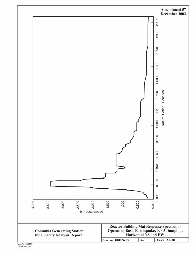
Amendment 57December 2003
Reactor Building Mat Response Spectrum -Operating Basis Earthquake, 0.005 Damping,
Horizontal NS and EW010126.05 3.7-18Figure
Form No. 960690
Draw. No. Rev.
4.00
0
3.50
0
3.00
0
2.50
0
2.00
0
1.50
0
1.00
0
0.50
0
0.00
0 0.00
00.
200
0.40
00.
600
0.80
01.
000
1.20
01.
400
1.60
01.
800
2.20
02.
400
Nat
ural
Per
iod
- Sec
onds
Acceleration (G)
2.00
0
Columbia Generating StationFinal Safety Analysis Report
LDCN-02-000
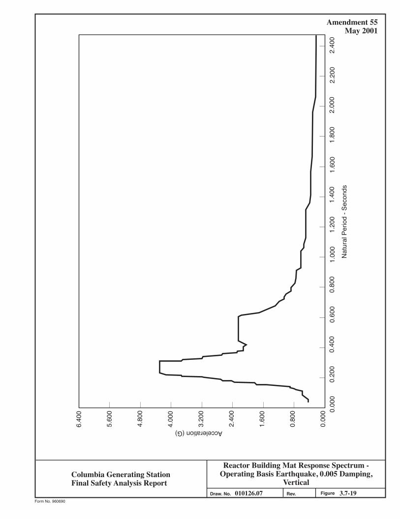
Amendment 55May 2001
Reactor Building Mat Response Spectrum -Operating Basis Earthquake, 0.005 Damping,
Vertical010126.07 3.7-19Figure
Form No. 960690
Draw. No. Rev.
6.40
0
5.60
0
4.80
0
4.00
0
3.20
0
2.40
0
1.60
0
0.80
0
0.00
0 0.00
00.
200
0.40
00.
600
0.80
01.
000
1.20
01.
400
1.60
01.
800
2.20
02.
400
Nat
ural
Per
iod
- Sec
onds
Acceleration (G)
2.00
0
Columbia Generating StationFinal Safety Analysis Report

Amendment 55May 2001
Reactor Building Mat Response Spectrum - SafeShutdown Earthquake, 0.01 Damping, Horizontal
NS and EW010126.08 3.7-20Figure
Form No. 960690
Draw. No. Rev.
6.40
0
5.60
0
4.80
0
4.00
0
3.20
0
2.40
0
1.60
0
0.80
0
0.00
0 0.00
00.
200
0.40
00.
600
0.80
01.
000
1.20
01.
400
1.60
01.
800
2.20
02.
400
Nat
ural
Per
iod
- Sec
onds
Acceleration (G)
2.00
0
Columbia Generating StationFinal Safety Analysis Report

Amendment 55May 2001
Reactor Building Mat Response Spectrum - SafeShutdown Earthquake, 0.01 Damping, Vertical
010126.09 3.7-21FigureForm No. 960690
Draw. No. Rev.
6.40
0
5.60
0
4.80
0
4.00
0
3.20
0
2.40
0
1.60
0
0.80
0
0.00
0 0.00
00.
200
0.40
00.
600
0.80
01.
000
1.20
01.
400
1.60
01.
800
2.20
02.
400
Nat
ural
Per
iod
- Sec
onds
Acceleration (G)
2.00
0
Columbia Generating StationFinal Safety Analysis Report

Reactor Building-Seismic AnalysisComparison of Responses
910402.17 3.7-22Figure
Amendment 53November 1998
Form No. 960690
Draw. No. Rev.
653.125
605.875
567.375
547.000
521.000
500.000
470.000
443.000
434.271
414.230
1
2
3
4
5
6
7
8
9
10
Transitional Accelerations (G)0.0 0.1 0.2 0.3 0.4 0.5 0.6 0.7 0.8 0.9 1.0 1.1 1.2 1.3 1.4
Time History Analysis (Max. Acceleration)
Spectrum Analysis (Using Design Response Spectra)
Spectrum Analysis (Using Synthetic Time History Response Spectra)
Columbia Generating StationFinal Safety Analysis Report

COLUMBIA GENERATING STATION Amendment 59 FINAL SAFETY ANALYSIS REPORT December 2007
LDCN-05-009, 06-014 3.8-1
3.8 DESIGN OF SEISMIC CATEGORY I STRUCTURES The nuclear steam supply system (NSSS) is housed in a steel primary containment vessel that has the ability to function as an independent structure. The primary containment vessel is housed in a reactor building also containing fuel storage and handling equipment and equipped with an overhead crane. The primary containment vessel for the NSSS is designed to confine the effects of a postulated nuclear accident and to limit the discharge of radioactive products to within levels specified in 10 CFR Part 50.67. The Seismic Category I structures, which are part of a complex of buildings in close proximity to each other, are the reactor building, the diesel generator building, and portions of the radwaste and control building. The portions of the radwaste and control building which are Seismic Category I are the radwaste area and the control room tower. The radwaste area encompasses the foundation mat, the walls and all internal structures from the top of mat el. 437 ft to and including the reinforced-concrete slab at el. 467 ft. The control room tower consists of the vertical portion of the building encompassing the area of the control room. The turbine generator building is a modified non-Category I seismic structure which is dynamically analyzed and designed to withstand the effects of an safe shutdown earthquake (SSE) and maintain its structural integrity thus providing adequate protection for the portions of the steam system designed as Seismic Category I, as defined in Regulatory Guide 1.29, Revision 3. The reactor building consists of a dual barrier: the steel primary containment vessel and the reactor building which provides secondary containment. The primary containment vessel contains the drywell, suppression chamber, structural floor separating the drywell from the suppression chamber, sacrificial shield wall (SSW), and reactor pedestal. The reactor building secondary containment encloses the biological shield wall, spent fuel storage pool, dryer-separator pool, and the reactor well pool. Seismic Category I structures that are not part of the building complex are two adjacent spray ponds, each provided with an integrally constructed standby service water pump house, and the condensate storage tank retaining area. The major structures in the reactor building and principal dimensions are shown in Figures 3.8-1, 3.8-2, and 3.7-13. The seismic analysis methods and models used to obtain seismic loads and floor response spectra, soil/structure interaction, the damping values used, and the seismic input at the base of the buildings are discussed in Section 3.7. Although the reactor building, radwaste and control building, diesel generator building, and turbine generator building are in close proximity to each other, they are supported on separate foundation mats. No interaction between these mats was considered. Each mat and its

COLUMBIA GENERATING STATION Amendment 53 FINAL SAFETY ANALYSIS REPORT November 1998
3.8-2
superstructure was analyzed separately for soil-structure interaction due to horizontal and vertical earthquake motions. The seismic design of the buildings was based on a parametric study for a wide range of soil properties. Thus, uncertainties in the soil properties and frequencies are adequately accounted for in the design. Each of the Seismic Category I structures in the complex is physically separated from the other, above and below grade, in order to accommodate differential seismic displacements and thermal expansion. Abutting walls between buildings, which are separated by only a few inches, are designed to resist wind forces and tornado effects including tornado-generated missiles and pressure drop. The tornado and wind forces on roofs and external walls were computed as indicated in Section 3.3. The seismic analysis of the reactor building included interaction between soil, foundation mat, and superstructures using lumped mass-spring, discrete models as described in Section 3.7. Conservative soil and structure damping parameters are included in the model. The response spectrum and time-history methods of analysis were used to determine the responses of the structures. Time histories of displacements and accelerations at the top of the reactor building mat and at the lumped masses, which usually represent floor slabs, are the main output of the time-history analysis. This output was used as input for time-history analyses, as required, of the main components of the NSSS (the reactor vessel and internals) as well as to generate floor response spectra which were used in the seismic analyses and design of safety-related systems, equipment, and components housed in the Seismic Category I structures. In addition, moments and shears were obtained for comparison with results obtained from response spectrum analyses. Response spectrum analyses were used for determining shears and moments for the final design of each of the structural components of the reactor building. These are discussed in Sections 3.8.2, 3.8.3, 3.8.4, and 3.8.5. 3.8.1 CONCRETE CONTAINMENT VESSEL (Not Applicable to CGS) Columbia Generating Station (CGS) has a steel containment vessel (see Section 3.8.2). 3.8.2 STEEL CONTAINMENT VESSEL (ASME Class MC Components) The capability of the primary steel containment vessel to withstand the hydrodynamic effects resulting from actuation of safety/relief valves (SRV) and specified loads associated with postulated loss-of-coolant accidents (LOCAs), and the applicable modifications were addressed in the Plant Design Assessment Report (DAR) for SRV and LOCA Loads. See Appendix 3A

COLUMBIA GENERATING STATION Amendment 59 FINAL SAFETY ANALYSIS REPORT December 2007
LDCN-05-009 3.8-3
which identifies the loads and effects which are most important to the design of the CGS plant and describes the CGS plant capability with respect to the hydrodynamic loading phenomena during SRV actuations and postulated LOCA events. 3.8.2.1 Description of the Primary Containment Vessel The basic safety objective of the primary containment system is to provide the capability in the event of a postulated LOCA of limiting the release of fission products to the plant site environs so that offsite doses are in compliance with the limits specified in 10 CFR Part 50.67. To meet the basic safety objective, several contributory objectives are achieved by the system or one or more of its components, including
a. Capability to withstand the peak transient pressures and temperatures which could occur due to postulated design basis LOCA; i.e., a mechanical failure of the reactor primary system equivalent to the circumferential rupture of one of the reactor coolant recirculation system pipes,
b. Capability to maintain the functional integrity of the primary containment
indefinitely after the postulated design basis LOCA, c. The primary containment design permits filling the primary containment system
drywell with water to a level above the reactor core, d. The primary containment system is protected against missiles from internal or
external sources and excessive motion of pipes, which could directly or indirectly endanger the integrity of the primary containment,
e. Capability to withstand fluid jet forces associated with the flow from the
postulated rupture of any pipe within the containment, f. Capability of limiting leakage during and following the postulated design basis
accident to values less than leakage rates which would result in offsite doses greater than the reference doses in 10 CFR Part 50.67,
g. Means of conducting the flow from postulated pipe ruptures, including the
design basis rupture of a recirculation line to the pressure suppression pool, to rapidly condense the steam portions of the flow so that the peak transient pressure is less than containment design pressure, to distribute such flow uniformly throughout the pool and to limit pressure differentials between the drywell and the pressure chamber during the various postaccident cooling modes, and

COLUMBIA GENERATING STATION Amendment 53 FINAL SAFETY ANALYSIS REPORT November 1998
3.8-4
h. Capability for rapid isolation of the primary containment to provide a containment barrier sufficient to maintain leakage within permissible limits.
The primary containment vessel is a free-standing steel pressure vessel. It utilizes the pressure suppression technique through the Mark II over-under configuration. The primary containment vessel and its appurtenances comply with the requirement of the ASME Code, Section III, Subsection NE-Class MC Components, 1971 Edition through Summer 1972 Addenda. It is designed to resist all normal operating loads, loads resulting from the postulated design basis accident as well as those loads associated with the operating basis earthquake (OBE) and SSE. The design also accounts for stresses induced by thermal expansion. The drywell floor which divides the drywell and suppression chamber is a reinforced-concrete slab supported by steel beams and concrete columns. The drywell floor to primary containment vessel gap is closed off by means of a floor seal shown in Figure 3.8-3. This configuration permits unrestrained expansion of the containment shell under differential thermal expansion and pressure loadings. The containment vessel is enclosed in a reinforced-concrete biological shield wall for shielding purposes and is separated from the reinforced concrete by an annulus of compressible isolation material, approximately 2 in. thick. The concrete wall thickness is governed by shielding requirements but also serves as a support for the reactor building floors. Shielding over the top of the drywell is provided by removable, segmented, reinforced-concrete shield plugs. The drywell is located directly above the wetwell. The drywell configuration is basically a frustum of a cone with removable ellipsoidal top closure head. The suppression chamber (wetwell) is cylindrical with an ellipsoidal base. The primary containment vessel is anchored to the concrete mat foundation. The bottom of the suppression chamber is lined on the inside with reinforced concrete. The concrete mat foundation under the suppression chamber is a common foundation supporting the steel primary containment vessel, including all equipment and structures therein, and the reactor building of which the primary containment vessel is a part. The drywell floor serves as a pressure barrier between the drywell and suppression chamber. The top closure head of the drywell is bolted to a steel flange attached to the top of the containment vessel. The drywell houses the reactor vessel and its associated primary system. The primary function of the drywell is to contain the effects (i.e., mass and radiation) of a LOCA, and to direct the steam released from a primary system pipe break into the suppression chamber pool to limit the total pressure rise during a LOCA. Under normal operating condition (normal condition) a fatigue analysis is performed in accordance with the requirements of ASME Code Section III. Under emergency condition, the jet impingement force of 534 kips as outlined in Section 3.8.2.3 might cause local yielding of the drywell shell. An analysis (plastic analysis in accordance with the requirements of the ASME Code Section III) demonstrates that rupture will not occur. Local deformation caused by the jet impingement force does not affect the leak tightness of the containment vessel.

COLUMBIA GENERATING STATION Amendment 53 FINAL SAFETY ANALYSIS REPORT November 1998
3.8-5
The analysis of the jet impingement effects on the primary containment vessel (Reference 3.8-21) is summarized as follows:
a. Phase 1 - The conical region of the containment shell was modeled and a general shell of revolution analysis was performed using the HYBOS computer program (Reference 3.8-22).
Two critical locations were chosen for independent application of the jet force. One, located approximately in the middle of two box ring stiffeners, is a logical candidate for maximum deflection; the second, located on the thinnest nearly adjacent to a stiffener, is a location where largest curvatures could occur if the shell contacts the concrete biological shield wall spaced 2 in. from the shell. Since the impinged area (429 in.2) subtends only a small arc of the total periphery, a Fourier harmonic expansion of 11 terms is used to represent the jet forces of 534 kips. The response to gravity, static seismic, and design pressure loads were also computed. The results of the most severe combinations of the loads (Appendixes C and D of Reference 3.8-21) show that the shell will contact the concrete for either candidate jet force location; consequently the elastic analysis is not valid in the immediate area of the jet load. The largest computer stresses were found for the second location and exceeded yield; therefore, an elastic-plastic analysis was next performed for that critical region;
b. Phase II - A local finite element elastic-plastic model was analyzed using the
DYPLAS computer program which is capable of treating nonlinear inelastic materials.
The boundaries of this model as shown in Figure 3.8-4 are structurally remote from the jet-impinged area, indicated by cross-hatching. The displacements from the general shell analysis, therefore, were used as displacement boundary conditions. Inelastic deformation, strains, and stresses were computed for all finite elements during selected steps of load applications; and
c. Stress evaluation was based on the ASME Boiler and Pressure Vessel (B&PV)
Code, Section III, Subsection NE, Class MC Components, NE-3131.2 and Appendix F, 1974 edition. 3.1 Code Requirements
Pm <σm

COLUMBIA GENERATING STATION Amendment 53 FINAL SAFETY ANALYSIS REPORT November 1998
3.8-6
PL <1.5 σm where σm = 0.85 x 0.7 x Su = 0.595 Su From Table I-1.1, for SA-516, Grade 70 Steel: Su - 70,000 psi at 345°F Therefore: σm - 41,650 psi To meet code requirements: Pm <41,650 psi PL <62,475 psi
3.2 Stress Evaluation From Appendix J of Reference 3.8-21 (Pm)max = 29,943 psi <41,650 psi which occurs on upper edge of model (Figure 3.8-4) (PL)max = 36,305 psi <62,475 psi which occurs on the lower portion of the impinged region (Figure 3.8-4) Therefore code requirements are met.
The ductility ratio is defined as the maximum response of an elasto-plastic structure to a prescribed loading function divided by the response of the same structure to the load at incipient plasticity. The maximum radial displacement at incipient plasticity was computed and is shown in computer Appendix I to Reference 3.8-21 as 0.4335 in. The maximum radial deflection of 2.0 in. was the spacing between shell and shield.

COLUMBIA GENERATING STATION Amendment 53 FINAL SAFETY ANALYSIS REPORT November 1998
3.8-7
Thus the ductility ratio might be considered to be 2.00/0.4335 = 4.6 However, since the maximum deflection of the shell is limited by contact with the concrete of the biological shield; the ductility ratio here may not be as meaningful a design parameter as it is in other cases. A more significant measure of structural integrity against cracking and ultimate leakage may be the most severe local principal cumulative strain. The most severely strained metal lies on the outside surface of the vessel shell near node 67 as shown in Figure 3.8-4. This strain is the maximum inelastic cumulative strain based on a computed nonlinear strain distribution through the vessel wall. Its value is 4%. Figure 3.8-5 shows the minimum elongation to failure of ASTM A516 Grade 70 steel as a function of temperature. Over the range of 70°F to 350°F this has a least value of 14.8%. An estimate of the factor of safety may then be said to be
F S. . ..
.= =14 84 0
3 7
Although failure strains in complex strain fields do not correlate precisely with results of one-dimensional ductility tests, the factor of safety, as computed above, is deemed ample. The criteria used in the seismic design of the containment system is based on the responses of the containment system to earthquake excitation. The responses are derived from the analysis of a mathematical model developed to represent the containment vessel. Section 3.7 outlines methods of analysis, modeling techniques, the seismic input, and the soil-structure interaction effects. All ferrous materials of plates, forgings, castings, and pipes for ASME Code, Class MC with thickness greater than 5/8 in. are Charpy V-notch impact tested at 0°F in accordance with the ASME Code, Section III, Paragraph NE-2300. Materials for ASME Code, Class 1 components are impact tested in accordance with NB-2300. The drywell will not be pressurized or subjected to substantial stress at temperatures below 30°F. The principal containment design parameters are listed in Table 3.8-1.

COLUMBIA GENERATING STATION Amendment 53 FINAL SAFETY ANALYSIS REPORT November 1998
3.8-8
The physical dimensions of the steel primary containment vessel are
a. The diameter of the cylindrical portion at the base of the cone is approximately 86 ft,
b. The diameter at the top of the cone is approximately 39.5 ft and then narrows to
32 ft to carry the removable head, c. Ellipsoidal bottom head with a ratio of 2:1 has an inside height of approximately
21.5 ft, d. The removable ellipsoidal top closure head has an inside height of
approximately 15.5 ft, e. The drywell shell height is approximately 99 ft, f. The suppression chamber shell height is approximately 72 ft, and g. Overall shell height is approximately 171 ft.
The primary containment vessel shell plate thicknesses vary. Typical thicknesses are as follows:
a. Bottom ellipsoidal head: from 7/8 in. to 1.5 in., b. The suppression chamber cylinder: from 1-5/16 in. to 1.5 in., c. The drywell conical section: from 0.75 in. to 1.5 in., and d. The removable top ellipsoidal head: 15/16 in.
Material thicknesses meet requirements of the ASME Code Section III, Paragraphs NE-3133 and NE-3324. The primary containment vessel is reinforced with internal vertical and horizontal stiffeners to satisfy design requirements of the various loading combinations and conditions. Fully circumferential rings, attached to the inside face of the primary containment vessel are furnished at el. 516 ft 6 in. and 542 ft 7.25 in. The basic function of these rings is to support pipe whip protection framework and to adequately distribute pipe whip loading into the vessel. The method used to ensure that there is an adequate clearance between the steel primary containment vessel and the concrete biological shield wall and which will account for differential thermal expansion is illustrated in Figure 3.8-2 and described as follows:
a. A system consisting of approximately 2-in.-thick polyurethane flexible foam sheets, butted at their joints and cemented directly to the containment shell, is

COLUMBIA GENERATING STATION Amendment 53 FINAL SAFETY ANALYSIS REPORT November 1998
3.8-9
used. The exterior surface sealed with laminated fiberglass reinforced polyester, epoxy jointed, panels which are bonded to the polyurethane sheets;
b. Steel anchor fasteners are attached to the fiberglass reinforced polyester panels,
and used for anchoring the inner end of the form ties which extend to the forms on the outside face of the concrete biological shield wall. These fasteners are mounted on the fiberglass reinforced plastic prior to bonding of the flexible foam;
c. The fiberglass panel joints are taped and filled with epoxy so that the entire
assembly forms a shell around the containment vessel with the polyurethane material set against and bonded panels thereby are permanent inner forms for the pouring of the concrete structure;
d. Drywell penetrations which extend from the containment vessel shell through
the concrete biological wall, are surrounded with concentric sleeves. These pipe sleeves are joined to the fiberglass shell using fiberglass tape and epoxy resins. This technique similarly provides a form for the concrete and maintains adequate clearance between the penetrations and the sleeves to accommodate thermal expansion;
e. The polyurethane foam material is chosen for its resistance to the environmental
conditions likely to exist during its service life. Although normal inservice temperature ranges from 95°F to 135°F (average) and 150°F (local), the polyurethane which is used is capable of withstanding temperatures in excess of the LOCA temperature of 340°F. Furthermore, this material is self extinguishing in accordance with ASTM D-1692;
f. The sizing of the expansion gap in which the foam sheet is placed is based on an
ultimate steel shell temperature of 340°F and an internal pressure of 45 psig following a postulated reactor LOCA. The external compressive stress applied to the containment vessel by the polyurethane foam, due to vessel thermal expansion from ambient conditions, ranges from 1.2 to 1.5 psi at normal operating and LOCA temperatures. At these temperatures the stress-strain curve for the polyurethane foam is nearly linear between 5% and 60% compression, ranging from approximately 1.2 psi at 5% compression to 1.8 psi at 60% compression. These properties are not significantly affected by the level of radiation exposure received over the plant life; and
g. The above design, materials, and construction of the containment vessel
expansion gap provides sufficient space for thermal expansion of the steel containment vessel shell. Moreover, this method of construction prevents either concrete or other foreign material from entering and/or reducing the gap. Local

COLUMBIA GENERATING STATION Amendment 53 FINAL SAFETY ANALYSIS REPORT November 1998
3.8-10
stress areas are thereby prevented, and the primary containment system is capable of accommodating both normal operating as well as postulate accident conditions.
The steel primary containment vessel, including all penetrations and welded attachments, is designed to act as a structural component within the reactor building as described in Section 3.8.2.4. The general configuration, and elevations are shown in Figures 3.8-1 and 3.8-2. The primary containment vessel is provided with two concentric circular skirts on the bottom ellipsoidal head integral with the vessel. The skirts are anchor bolted to the concrete foundation mat. The bottom ellipsoidal head and the upper portion of the skirts connected to the head are considered part of containment pressure boundary in accordance with the ASME Code Section III. The lower portion of the skirts follow the requirements of the American Institute of Steel Construction (AISC) Code. The skirts are backed up by concrete fill. The concrete fill and the concrete foundation mat discussed in Section 3.8.5 are not part of the containment vessel. 3.8.2.1.1 Description of Penetrations Penetrations through the primary containment vessel are as follows. 3.8.2.1.1.1 Pipe Penetrations. Two general types of pipe penetrations are provided. The two types differ depending on whether the penetration is subject to a hot or cold operational environment. The cold penetrations pass through the steel primary containment vessel and are welded directly to it. The piping is normally welded directly to the penetration nozzles. The piping design includes the effects of thermal motion of the containment shell at the penetration connections. The hot penetrations and multiple piping penetrations do not come in direct contact with the steel shell of the primary containment vessel. These penetrations pass through vessel shell nozzles which are welded to the steel shell of the primary containment vessel and function as thermal sleeves. Containment closure is accomplished by means of closure plates or flued head fittings, welded to the penetration nozzle and the piping at a suitable distance outside the containment shell. Detailed descriptions of pipe penetrations are given in Section 3.8.6. 3.8.2.1.1.2 Electrical Penetrations. Containment electrical penetrations are designed to safely accommodate all of the electrical requirements within the containment boundary. These are functionally grouped into low voltage power and control cable penetrations assemblies, medium voltage power cable penetration assemblies, signal cable penetration assemblies and thermocouple cable penetration assemblies. The medium voltage power cable electrical penetrations are canister type assemblies sized to be inserted into the containment vessel penetration nozzles. All other electrical penetrations are a unitized header plate assembly attached to the outboard end of the containment vessel penetration nozzles. Detailed descriptions of electrical penetrations are given in Section 3.8.6.

COLUMBIA GENERATING STATION Amendment 53 FINAL SAFETY ANALYSIS REPORT November 1998
3.8-11
3.8.2.1.1.3 Traversing In-Core Probe Penetrations. Five traversing in-core probe (TIP) guide tubes pass from the reactor building to the drywell through the primary containment vessel. The penetrations are a Type 2 (see Section 3.8.6.1.2) piping penetration modified with a welding neck flange attached outside the containment. This flange is itself modified with dual concentric O-ring grooves machined into the face, which retain elastomeric O-rings. To this is bolted a blank flange which has been drilled for both a between-O-ring test port and a central hole in which an instrument tubing “bulkhead union” fitting is retained. This single penetration point is sealed by seal welding between the bulkhead union and the blank flange. The TIP guide tubes are attached to both sides of their respective bulkhead unions by flare fittings. These penetrations are also discussed in Section 3.8.6.1.2. 3.8.2.1.1.4 Personnel Access Lock and the (Combined) Equipment Hatch and Control Rod Drive Removal Hatch. The drywell has one manually operated personnel air lock. This air lock consists of a cylindrical shell with two doors, one at each end of the shell. The cylindrical shell is approximately 8 ft 10.5 in. in diameter which is sufficient to provide 6 ft 8 in. high by 3 ft 4 in. wide door openings above the floor. The minimum clear horizontal distance not impaired by the door swing is 5 ft. Each door has double compressible seals with an air space between them so that each door may be individually tested. Each door is hinged and swings toward the drywell. The air lock doors are designed so as to permit either door to be operated from inside the drywell, inside the air lock, or outside the drywell. In addition, the air lock doors are interlocked to ensure that at least one door is locked when primary containment integrity is required. Signals and controls indicating the status of the doors are provided locally. The locking mechanisms are designed so that tight seals are maintained when the doors are subject to either the design internal or external pressure. A mechanical override is provided to permit temporary bypassing of the door interlock system to permit opening both doors under proper authorization. Quick acting equalizer valves are provided to equalize the pressure in the air lock when personnel enter or leave the primary containment vessel. The drywell has one equipment removal hatch. The equipment hatch cover is dished and has steel stiffeners. The hatch cover is bolted to a flanged steel sleeve welded to the primary containment vessel shell such that the hatch cover can be removed and reinstalled from outside the drywell. The equipment hatch and cover is entirely supported by the steel containment vessel. Double compressible seals with an air space between them are used to permit leak testing at any time. The inside diameter of the equipment hatch is approximately 12 ft 6 in. which provides a minimum clearance above the floor at the hatch of 10 ft 1.5 in. high by 7 ft 0 in. wide. Included within the equipment hatch cover is a control rod drive (CRD) removal hatch with its hinged cover. This hatch is provided with leak-testable, double-gasketed seals. The inside

COLUMBIA GENERATING STATION Amendment 53 FINAL SAFETY ANALYSIS REPORT November 1998
3.8-12
diameter of this hatch is approximately 1 ft 11 in. in diameter which provides a minimum clearance of 11 in. high by 1 ft 4 in. wide at the hatch. The personnel access lock and the equipment hatch extend radially outward across the annular gap of compressible isolation material and through the biological shield wall and are supported by the primary containment vessel only. Both the personnel air lock and the equipment removal hatch are designed to withstand the normal environmental conditions which may prevail during normal plant operation and to maintain their functional integrity during a postulated LOCA. The design meets the requirements of the ASME Code Section III, Subsection NE, Class MC Components. 3.8.2.1.1.5 Pressure Suppression Chamber Access Hatch. Access to the pressure suppression chamber is provided at one location in the cylindrical well of the chamber approximately 7 ft 6 in. above the suppression pool operating water level. This access hatch is approximately 3 ft 5 in. in diameter, extends radially outward, is supported by the vessel and has a leak-testable, double-gasketed, bolted cover which is normally closed and is opened only when primary containment is not required. The minimum clearance at the hatch is 2 ft 2.75 in. wide by 2 ft 5.5 in. high. The design meets the requirements of the ASME Code Section III, Subsection NE, Class MC Components. 3.8.2.1.1.6 Access for Refueling Operations. The drywell containment head is removed during refueling operations. This head is held in place by bolts and is sealed with a double seal. It is bolted closed when primary containment is required and is opened only when primary containment is not required. The gasket seal is capable of limiting the leakage to below the design rate and is capable of being independently tested. 3.8.2.1.2 Description of Crane Girder (Not Applicable to CGS) CGS does not have a crane girder inside containment. 3.8.2.1.3 Description of Vacuum Relief System See Figure 9.4-8 for an illustration of the vacuum relief system described below. Three 24-in. reactor building-to-wetwell vacuum relief lines, each containing a 24-in. vacuum breaker valve and an automatic air-operated butterfly valve, are provided between the reactor building and the suppression chamber. These valves prevent excessive vacuum from developing in the primary containment vessel from such causes as inadvertent containment spray actuation. Each butterfly valve is equipped with a spring-to-open, air-to-close operator which, during normal plant operation is maintained in a closed position by means of a control air supply

COLUMBIA GENERATING STATION Amendment 58 FINAL SAFETY ANALYSIS REPORT December 2005
LDCN-05-004 3.8-13
through a three-way solenoid pilot valve. The plant control air supply to the valve is backed up by a Quality Class I air supply system, consisting of an accumulator pressurized by the plant control air system and an independent 10 nitrogen bottle manifold located in the vehicle air lock (railroad bay) which will automatically maintain accumulator pressure on loss of air supply from the control air system (see Figure 3.8-7). On venting of air from the air-operators, the spring- actuated butterfly valves open. Venting is accomplished through remote manual deenergization of the solenoid pilot valve or by a signal from the differential pressure switch which deenergizes the solenoid pilot valve when the secondary containment atmospheric pressure is more than 0.5 psi higher (analytical limit) than the suppression chamber atmospheric pressure. Two limit switches, wired to indicator lights in the control room, are provided with each butterfly valve for position indication. One switch actuates when the valve is fully open and provides an alarm and “open” visual indication in the control room. The other switch actuates when the valve is fully closed and provides a “closed” visual indication in the control room (see Figure 3.8-8). In series with each butterfly valve is a single disk check valve. The disk is maintained in the closed position during normal operation by means of a spring-actuated lever arm and magnets embedded in the periphery of the disk. The magnetic and spring forces are overcome, and the disk opens when the pressure differential across the valve is within the range of 0.10 to 0.35 psi. The disk is fully open when the pressure difference is 0.5 psi. In addition, pneumatic actuators are provided for remote operation of the disk. Compressed air is supplied by the plant control air system through the pneumatic operator Quality Class I accumulator and backup nitrogen supply as shown in Figure 3.8-7. Each disk pneumatic operator consists of two air cylinders, one to open and one to close the disk. Each air cylinder is actuated through energization of a three-way solenoid pilot valve. The two solenoid pilot valves associated with each disk are operated by a remote manual switch in the control room. During normal operation the remote manual switches are in the neutral position and the solenoids are deenergized. Each valve disk is provided with contact probe sensors for position indication. These sensors are wired to indicator lights in the control room to provide open and closed position indication. An additional sensor is also wired to a light in the control room that indicates when the disk is fully open. Each reactor building to wetwell vacuum breaker is visually inspected at least once every 30 months. Nine 24-in. wetwell-to-drywell vacuum relief valves attached to the downcomers in the suppression chamber are provided to return noncondensables from the wetwell to the drywell to prevent too large an upward pressure differential across the diaphragm floor after a LOCA. Each wetwell-to-drywell vacuum relief valve assembly consists of two discs and seats which operate independently. The operation, controls, and position indication for each disc is as

COLUMBIA GENERATING STATION Amendment 57 FINAL SAFETY ANALYSIS REPORT December 2003
3.8-14
described above for the single disc check valves. During normal plant operation the control air supply line to these valve assemblies is isolated. Also, residual pressure is vented from the line following vacuum relief valve testing to prevent inadvertent valve opening. The vacuum breaker valves are sized to ensure that following design conditions are not exceeded.
a. The drywell internal design pressure of 2.0 psi below reactor building pressure, b. The suppression chamber internal design pressure of 2.0 psi below reactor
building pressure, and c. The upward design pressure difference across the diaphragm floor of 6.4 psi.
The design evaluation for the vacuum relief is discussed in Section 6.2.1.1.4. The vacuum relief valves are constructed to ASME Section III, Subsection NC for Class 2 components, 1974 Edition through the Summer 1975 Addenda. Electrical systems associated with the control and position indication for the reactor building to wetwell vacuum breaker valves and the drywell-to-wetwell vacuum breaker valves are not Class 1E since electrical failure or malfunction will not prevent operation or cause inadvertent actuation under postulated accident conditions. 3.8.2.1.4 Containment Pressure Boundaries The primary containment pressure boundaries for the steel primary containment vessel consist of those defined in Subarticle NE-1130 of the ASME Code Section III and the additional boundaries listed in the following:
a. The steel primary containment vessel shell including the top and bottom heads, and, as defined in the ASME Code Section III, Paragraphs NE-3364 and NE-4431, an upper portion of the skirts supporting the vessel, and
b. The attachment welds fastening pipe whip protection support rings, beam
supports, and pads to the vessel for purposes of supporting piping support members, walkways, platforms, monorails, brackets, or other members to the containment vessel.
3.8.2.1.5 Primary Containment Environmental Conditions The primary containment is designed to operate during all environmental conditions found in Section 3.11. See Table 3.8-2 for specific design conditions.

COLUMBIA GENERATING STATION Amendment 54 FINAL SAFETY ANALYSIS REPORT April 2000
3.8-15
3.8.2.2 Applicable Codes, Standards, Specifications, and Regulatory Guides 3.8.2.2.1 Codes, Standards, and Specifications The following describe the applicable codes, standards, specifications, code classification, and code compliance for the steel primary containment vessel.
a. The following sections of the ASME B&PV Code, 1971 Edition, including all addenda through Summer 1972 apply for the steel primary containment vessel.
Section II, Material Specifications Part A - Ferrous Part B - Welding Filler Metals Section III, Nuclear Power Plant Components Subsection NE, Class MC Components Section V, Nondestructive Examination Section IX, Welding Qualifications;
b. The AISC Specification for the Design, Fabrication, and Erection of Structural
Steel for Buildings, February 12, 1969, applies for the steel construction beyond the boundaries established for the steel containment vessel;
c. Steel Structures Painting Manual, Volume 2, Systems and Specifications, 1964
Edition with the 1968 Supplement and the January 1971 Editorial changes.
Specification SSPC-SP-6, SP-8 and SP-10;
d. Applicable ASTM and AWS Material Standard Specifications permitted by Article NE-2000 of III;
e. Applicable ASTM Standard Specifications for nondestructive methods of
examination referenced in Article X-3000 of Section III of the ASME Code; f. Plant Design Specification 2808-213; and g. National Electrical Code.
3.8.2.2.2 Code Classification The steel primary containment vessel is classified Class MC in accordance with Subarticle NA-2130, Section III of the ASME Code, 1971 Edition through the Summer 1972 Addenda.

COLUMBIA GENERATING STATION Amendment 59 FINAL SAFETY ANALYSIS REPORT December 2007
LDCN-06-014 3.8-16
3.8.2.2.3 Code Compliance 3.8.2.2.3.1 Containment Vessel. The steel shell and the top and bottom heads of the steel primary containment vessel, including all penetrations and attachments within the boundaries defined in Section 3.8.2.1.4, are designed and constructed in accordance with Subsection NE, Class MC Components, including the requirements for quality assurance of the Article NA-4000, and inspection requirements of Article NA-5000 of Section III of the ASME Code. 3.8.2.2.3.2 Code Stamp. The steel primary containment vessel is ASME Code stamped in accordance with requirements of the Code applicable to Class MC containment vessels. 3.8.2.2.3.3 Exceptions. No exceptions are taken to the requirements of Section III of the ASME Code for Class MC containment vessels. 3.8.2.2.3.4 Attachments. Structural steel attachments beyond the boundaries established for the steel primary containment vessel are designed and constructed according to the AISC Specification for the Design, Fabrication, and Erection of Structural Steel for Building, February 12, 1969, where applicable. Nonpressure vessel elements such as catwalks and interior beam connections with hatch floors are designed in accordance with the AISC Code. Stress intensity limits are in accordance with the allowable permitted by the AISC Code with the exception that, for loading combinations including OBE, no increase in allowable stress will be permitted. The inner and outer skirts for the support of the primary containment vessel are designed in accordance with Subarticle NE-3100 of Section III of the ASME Code. Supports for pipe whip guide rings are designed as described in Section 3.6. 3.8.2.2.4 Regulatory Guides The following regulatory guides related to the primary containment vessel are applicable to CGS. Their implementation is discussed in Section 1.8.
a. Regulatory Guide 1.7, Rev. 1 - Control of Combustible Gas Concentrations in
Containment Following a LOCA, b. Regulatory Guide 1.11, Rev. 0 - Instrument Lines Penetrating Primary Reactor
Containment, c. Regulatory Guide 1.28, Rev. 0 - Quality Assurance Requirements (Design and
Construction), d. Regulatory Guide 1.29, Rev. 3 - Seismic Design Classification,

COLUMBIA GENERATING STATION Amendment 54 FINAL SAFETY ANALYSIS REPORT April 2000
3.8-17
e. Regulatory Guide 1.46, Rev. 0 - Protection Against Pipe Whip Inside
Containment, f. Regulatory Guide 1.57, Rev. 0 - Design Limits and Loading Combinations for
Metal Primary Containment System Components, g. Regulatory Guide 1.63, Rev. 0 - Electric Penetration Assemblies in
Containment Structures for Water-Cooled Nuclear Power Plants, h. Regulatory Guide 1.84 - Code Case Acceptability - ASME Section III Design
and Fabrication, and i. Regulatory Guide 1.85 - Code Case Acceptability - ASME Section III Materials.
3.8.2.3 Loads and Loading Combinations The primary containment vessel is designed to withstand forces due to
a. Dead load, including permanent equipment loads and hydrostatic loads, b. Live loads, including movable equipment loads and other loads varying in
intensity and occurrence, c. Thermal effects and loads during startup, normal operating, and shutdown
conditions, based on the most critical transient or steady-state conditions, d. Earthquakes, e. Wind during construction, and f. Pressure and temperature effects, jet impingement, and missile impact all due to
pipe break accident. The vessel design includes analyses in the vicinity of the primary containment vessel penetrations for the penetration load combinations given in Section 3.8.6.3. 3.8.2.3.1 Design Pressures and Temperatures
a. Pressure suppression chamber
1. Internal design pressure 45 psig (LOCA pressure)

COLUMBIA GENERATING STATION Amendment 54 FINAL SAFETY ANALYSIS REPORT April 2000
3.8-18
2. External design pressure 2.0 psig (due to negative internal pressure) 3. Design temperature 275°F
b. Drywell
1. Internal design pressure 45 psig (LOCA pressure) 2. External design pressure 2.0 psig (due to negative internal pressure) 3. Design temperature 340°F
c. Pressure suppression chamber and drywell
1. Pneumatic over pressure 51.8 psig at test (115% of 45 psig) ambient temperature 2. Initial leak rate test Maximum permitted leakage rate of 0.5% of total weight of contained air per any 24 hour period at 38 psig test pressure.
d. Differential design pressure 25 psid (downward on drywell floor following a LOCA)
e. Differential design pressure 6.4 psid (upward on drywell floor following a LOCA)
f. Lowest service metal temperature 30°F
3.8.2.3.2 Operating Pressure and Temperature See Table 3.8-1 for normal operating pressures and temperatures.

COLUMBIA GENERATING STATION Amendment 54 FINAL SAFETY ANALYSIS REPORT April 2000
3.8-19
3.8.2.3.3 Dead Loads The following dead loads are transmitted directly through the concrete fill inside the bottom head of the primary containment vessel, through the continuous concrete fill directly under the bottom head and then into the reactor building foundation mat:
a. Concrete fill inside the bottom head of the primary containment vessel, b. Concrete columns in the suppression chamber and contributory portion of the
drywell floor supported by the columns, c. Contained air in the suppression chamber, d. Water in the suppression chamber, and e. Reactor vessel pedestal, reactor pressure vessel (RPV), SSW, and contributory
portion of the concrete drywell floor supported by the pedestal. The following are typical dead loads used in the design of the primary containment vessel:
a. Vessel and appurtenances, b. Water in the suppression chamber with coincident hydrostatic pressure, c. Attached equipment and supports, catwalks, platforms and attached piping, air
ducts, electrical ducts, conduit and trays, d. Header loads, e. Contained air, under test conditions, f. Weight of the gap filler material applied to the outside face of the shell (used
5 psf.), g. Design load on welding ring pads of 1500 lb per lineal foot acting in any
direction. Welding ring pads are in the drywell and are used for attaching pipe and duct hangers, hoist supports, etc. These pads are welded parallel to the containment vessel surface,
h. Stabilizer truss, i. Construction dead loads, e.g., scaffolds, and

COLUMBIA GENERATING STATION Amendment 54 FINAL SAFETY ANALYSIS REPORT April 2000
3.8-20
j. Water in the drywell with coincident hydrostatic pressure, under the flooded condition.
3.8.2.3.4 Live Loads The following are typical live loads used in the design of the primary containment vessel:
a. Live loads on the drywell floor, platforms and catwalks discussed in Sections 3.8.3.1.3 and 3.8.3.1.4,
b. Monorail live and impact loads, c. Live loads on floor section of personnel air lock (300 psf), equipment access
hatch (1000 psf), and suppression chamber access (150 psf),
d. Live load on temporary construction scaffolds, e. Operating weight of fluid in attached normally empty piping, headers and
penetrations, f. Head of water, 23 ft 6 in. high, on the refueling bellows seal with the
containment vessel head removed and coincident hydrostatic pressure (under the refueling condition), and
g. Same as Section 3.8.2.3.4(f) above except without the containment vessel head
removed (under the flooded condition). 3.8.2.3.5 Mechanical Piping Loads Mechanical piping loads consist of
a. Piping reactions during normal operating or shutdown conditions, based on the most critical transient or steady-state condition,
b. Pipe reactions under thermal conditions generated by a postulated break and
including (a) above, c. Equivalent static load generated by the reaction of a broken high-energy pipe
during a postulated break (and including an appropriate dynamic load factor to account for the dynamic nature of the load),

COLUMBIA GENERATING STATION Amendment 54 FINAL SAFETY ANALYSIS REPORT April 2000
3.8-21
d. Jet impingement equivalent static load generated by the design-basis accident (DBA) postulated break (and including an appropriate dynamic load factor to account for the dynamic nature of the load), and
e. Pipe reactions and thermal conditions during an event causing external pressure.
A description of certain loads included among those listed above follows: 3.8.2.3.5.1 Jet Forces in Drywell. The drywell shell, personnel air lock, equipment hatch, jet deflectors, and the removable top closure head are designed and constructed to withstand, in combination with other loads, jet forces consisting of either steam and/or water at 340°F and applied as follows: Jet Force
(kips) Area Subjected
(in2)
From the closure head flange 33 26 to the top of the head From the closure head flange 534 429 down to the drywell floor
A jet force is considered to occur in any direction but is not considered to occur simultaneously with another jet force; however, a jet force is considered to occur coincident with the drywell internal design pressure of 45 psig and design temperature of 340°F. Local yielding may take place on the drywell shell from the jet force, but the shell will not rupture. On the top closure head and other areas, where the shell is not backed up by concrete, the primary stresses resulting from this combination of loads do not exceed the values specified in the ASME Code Section III, Paragraph NE-3131(c) at a temperature of 340°F. 3.8.2.3.5.2 Vent Pipe (Downcomer) Thrusts. The vent pipes (downcomers) and their connections to the drywell floor are designed for the following loads:
a. Jet blowdown thrust
A jet force of 20,000 lb acting upward on each of the downcomers is considered to occur simultaneously with an internal design pressure of 20 psig and a design temperature of 275°F;
b. Initial and final test conditions
A force equal to 1.25 times the design pressure multiplied by the flow area of the vent pipe; and

COLUMBIA GENERATING STATION Amendment 54 FINAL SAFETY ANALYSIS REPORT April 2000
3.8-22
c. Accident conditions
Forces obtained from Section 3.8.2.3.5.2 (a) except that the temperature in the drywell is taken as 340°F and the temperature in the suppression chamber is taken as 275°F. The drywell floor concrete temperature is taken as 95°F.
3.8.2.3.5.3 Pipe Whip. Pipe whip protection support rings, which are fully circumferential rings, are attached to the primary containment vessel at el. 516 ft 6 in. and 542 ft 7.25 in. The basic function of these rings is to support pipe whip protection framework and to adequately distribute pipe whip loading into the vessel. The pipe rupture loading is applied to the vessel through the support rings during normal operating conditions at normal operating temperature and at atmospheric pressure, as well as during an incident condition at maximum temperature of 340°F and at design pressure. The primary containment vessel analysis include the effects of a pipe rupture at any single location. For further discussion on function and design of load transmitting members see Section 3.6. 3.8.2.3.6 Thermal Loads The thermal loads in the primary containment vessel steel are produced by the presence of temperature gradients within the containment and its appurtenances. Thermal effects and loads during normal operating conditions are based on the most critical transient or steady-state condition. Thermal loads are also considered under thermal conditions generated by a postulated pipe break. 3.8.2.3.7 Construction Loads
a. Wind load in the projected area of the steel primary containment vessel before the completion of the reactor building in accordance with Reference 3.8-1, with a basic wind of 100 mph as discussed in Section 3.3, and
b. Snow loads before the completion of the reactor building.
3.8.2.3.8 Missile Loads There are no external missile loads considered since the primary containment vessel is protected by the biological shield wall. Potential internal missiles and protection provisions are discussed in Section 3.5. 3.8.2.3.9 Loss-of-Coolant Accident Loads The LOCA imposes pressure and thermal loads plus jet forces associated with coolant flow from any ruptured pipe within the containment. This LOCA loading condition is determined

COLUMBIA GENERATING STATION Amendment 54 FINAL SAFETY ANALYSIS REPORT April 2000
3.8-23
by analysis of the transient pressure and temperature effects which occur during a LOCA. The governing design condition for the LOCA is discussed in Section 6.2. 3.8.2.3.10 Accident Recovery Loads Among the postulated LOCAs there may be an accident within the drywell that requires a contingency flooding of the pressure suppression chamber and the drywell to an elevation above the top of the active fuel zone in the reactor vessel as indicated in Section 3.8.2.3.12h; and, with the primary containment vessel head not removed, the reactor vessel cavity outside the primary containment vessel and above the refueling bellows seal flooded to a level above the refueling bellows seal noted in Section 3.8.2.3.12. The structural design criteria for the primary containment vessel are consistent with the provisions of Regulatory Guide 1.57, Revision 0 (issued June 1973) except with respect to the stress limits specified in Section C-1-b (2) of the guide for the load combinations of accident recovery flooding plus OBE. For the flooded condition loading combination described in Section 3.8.2.3.12h, the various stress categories shown in ASME Code Section III, Figure NB 3222-1 are satisfied, using allowable primary general membrane stress intensities specified in the ASME Code Section III paragraph NE 3131(c)(1) and NE 3131(c)(2). The stress limits for the primary containment vessel for the accident recovery flooding plus OBE load condition are shown in Section 3.8.2.5.3. Justification for these stress limits, which are higher than those outlined in Regulatory Guide 1.57 is based on the extremely low probability that flooding would ever be required. 3.8.2.3.11 Seismic Loads Equivalent static loads are developed through a dynamic analysis of Seismic Category I structures subjected to the OBE and the SSE. 3.8.2.3.12 Loading Combinations The loading combinations considered in the design of the steel primary containment vessel apply to both the drywell and suppression chamber, unless otherwise noted, and include the following typical loads:
a. Initial proof load test condition (at ambient temperature)
This is a normal condition.
1. Dead load

COLUMBIA GENERATING STATION Amendment 54 FINAL SAFETY ANALYSIS REPORT April 2000
3.8-24
(a) Vessel and appurtenances, (b) Water in suppression chamber with coincident hydrostatic
pressure, (c) Concrete drywell floor, (d) Catwalks and platforms, (e) Contained air, and (f) Header loads, empty;
2. Live Loads
(a) On drywell floor, and (b) On catwalks and platforms;
3. Design pressure, internal, in suppression chamber; 4. Test pressure, internal in the drywell; 5. Lateral wind or OBE, horizontal and vertical, whichever is more severe;
and 6. Jet blowdown thrusts in the suppression chamber taken at columns,
reactor pedestal and penetrations;
b. Final proof load test condition (at ambient temperature)
This is a normal condition.
1. Dead load
Same items as in item a.1, plus:
(a) Drywell equipment, supports, platforms, and attached empty pipe and headers,
(b) Gap fill material, and

COLUMBIA GENERATING STATION Amendment 54 FINAL SAFETY ANALYSIS REPORT April 2000
3.8-25
(c) Piping, ducts, hoist support loads, etc., on welding ring pads in drywell described in Section 3.8.2.3.3.h.
2. Live load
Same items as in item a.2;
3. Design pressure, internal (drywell and suppression chamber); 4. External pressure of 2 psi (consists of 2 psig restraint due to filler
material); 5. Seismic OBE, horizontal, and vertical; 6. Jet blowdown thrusts in suppression chamber (same as item a.6); and 7. Drywell refueling bellows seal loads, namely, the effects of the spring
action of refueling bellows seal onto the containment vessel;
c. Normal operating condition (at atmospheric pressure and at operating temperature ranging from 50°F to values specified in Table 3.8-1).
This is a normal condition with OBE and is in conformity with ASME Code, Section III, Paragraph NE-3131(c)(1) or (c)(2) with SSE. 1. Dead load
(a) Vessel and appurtenances, (b) Water in suppression chamber and coincident hydrostatic
pressure, (c) Concrete drywell floor, (d) Catwalks in suppression chamber, (e) Drywell equipment, supports, platforms and attached pipes,
headers, air ducts, electrical ducts, conduits, and trays, (f) Gap filler material, and (g) Loads on welding ring pads (same as in item b.1);

COLUMBIA GENERATING STATION Amendment 54 FINAL SAFETY ANALYSIS REPORT April 2000
3.8-26
2. Live load (a) On drywell floor, (b) On catwalks and platforms, (c) Personnel and equipment access openings in the drywell and on
personnel access openings in suppression chamber, and (d) Operating weight of fluid in normally empty piping and
penetrations; 3. External pressure of 2 psi (same as in item b.4); 4. Seismic OBE or SSE, horizontal and vertical, including seismic loads
from shear lugs between the drywell floor and the containment vessel and seismic loads from the reactor vessel stabilizers;
5. Jet blowdown thrusts in suppression chamber (same as in item a.6); 6. Drywell refueling bellows seal loads; 7. Drywell floor seal loads; and 8. Thermal loads described in Section 3.8.2.3.6
d. Refueling condition (with containment vessel head removed, at atmospheric pressure and at operating temperature ranging from 50°F to values specified in Table 3.8-1). This is a normal condition. 1. Dead load
Same as in item c.1; 2. Live load
Same items as in item c.2 plus water load due to 23 ft 6 in. head of water on the refueling bellows seal, at the top flange of the drywell, with coincident hydrostatic pressure;
3. External pressure of 2 psi (same as in item b.4);

COLUMBIA GENERATING STATION Amendment 54 FINAL SAFETY ANALYSIS REPORT April 2000
3.8-27
4. Seismic OBE, horizontal and vertical; 5. Drywell refueling bellows seal loads; 6. Drywell floor seal loads, namely, the effects of spring action on floor
seal on to the containment vessel; and 7. Thermal loads described in Section 3.8.2.3.6;
e. Accident condition (at drywell maximum temperature of 340°F and suppression chamber maximum temperature of 275°F). This is a normal condition with SSE in conformance with ASME Code Section III, Paragraph NE 3131(c), or with OBE. 1. Dead load
Same items as in item c.1;
2. Live load
(a) On drywell floor, (b) On catwalks and platforms, and (c) Operating fluid weight in normally empty piping and
penetrations;
3. Internal design pressure in drywell of 45 psig decaying to a negative pressure of 2 psig at 135°F;
4. Internal design pressure in suppression chamber of 45 psig decaying to a
negative pressure of 2 psig at 275°F;
5. External pressure of 2 psi (same as in item b.4); 6. Seismic OBE or SSE, horizontal and vertical, including seismic loads
from shear lugs between the drywell floor and the containment vessel, and seismic loads from the reactor vessel stabilizer;
7. Jet blowdown thrusts in suppression chamber (same as in item a.6);

COLUMBIA GENERATING STATION Amendment 54 FINAL SAFETY ANALYSIS REPORT April 2000
3.8-28
8. Jet forces on drywell shell, personnel air lock, equipment hatch, drywell floor, jet deflectors on the drywell floor over the downcomers and at the floor periphery, and the head of the containment vessel. See Section 3.8.2.3.5.1;
9. Drywell refueling bellows seal loads;
10. Drywell floor seal loads; 11. Effects of header jet nozzle loads; and 12. Thermal loads described in Section 3.8.2.3.6;
f. Accident condition with pipe whip (at drywell maximum temperature of 340°F and suppression chamber temperature of 275°F). This condition includes pipe whip support load effects onto the containment vessel shell. Loads are the same as those in item e, with the addition of loads on pipe whip support rings due to main steam or reactor feedwater pipe ruptures;
g. Normal condition with pipe whip (at atmospheric pressure and at operating temperature ranging from 50°F to values specified in Table 3.8-1). Earthquakes used are OBE or SSE. Stresses are in conformance with ASME Code, Section III, Paragraph NE-3131(c)(1) or (c)(2). Loads are the same as those in item c, with the addition of loads on pipe whip support rings due to main steam or reactor feedwater pipe ruptures;
h. Flooded Condition (with drywell flooded to el. 552 ft 0 in., which is approximately 1 ft above the top of the active fuel zone in the reactor vessel, suppression chamber and downcomer vent system flooded; and, with the containment vessel head not removed, reactor vessel cavity outside the containment vessel and above the refueling bellows seal flooded to a level 23 ft 6 in. above the refueling bellows seal). 1. Dead load
(a) Vessel and appurtenances, (b) Concrete drywell floor,

COLUMBIA GENERATING STATION Amendment 54 FINAL SAFETY ANALYSIS REPORT April 2000
3.8-29
(c) Catwalks in suppression chamber, (d) Drywell equipment, supports, platforms and attached piping,
headers, air ducts, electrical ducts, conduits, and trays, (e) Gap filler material, (f) Loads on welding ring pads same as in item b.1, (g) Suppression chamber filled with water at a maximum temperature
of 212°F and with coincident hydrostatic pressure, and (h) Drywell filled with water to el. 552 ft 0 in. at a maximum
temperature of 212°F and with coincident hydrostatic pressure;
2. Live load (a) Operating weight of fluid in normally empty piping and
penetrations, and (b) Water load on the refueling bellows seal at the top flange of the
containment vessel, and coincident hydrostatic pressure, due to the reactor vessel cavity outside the containment vessel above the refueling bellows seal flooded to a level 23 ft 6 in. above the seal, as described in item h;
3. External pressure of 2 psi (same as in item b.4); 4. Seismic OBE, horizontal and vertical, including loads from shear lugs
between the drywell floor and the containment vessel, and loads from the reactor vessel stabilizer; and
5. Drywell floor seal loads.
3.8.2.4 Design and Analysis Procedure The steel primary containment vessel, which consists of a vertical free-standing bell-jar shell, bottom and top ellipsoidal heads and numerous penetrations and attachments, is considered to act as an independent structural component within the reactor building. The bottom head, which is supported by the concrete mat foundation, is designed as a pressure tight and leaktight membrane.

COLUMBIA GENERATING STATION Amendment 54 FINAL SAFETY ANALYSIS REPORT April 2000
3.8-30
The steel primary containment vessel is designed to the ASME Code Section III, Subsection NE for Class MC components. Those areas of the steel primary containment vessel that are free from structural discontinuities and experience no discontinuity stresses due to thermal and/or mechanical loads are designed in accordance with Subarticle NE-3300 of ASME Code Section III. For the configurations and loadings located throughout the steel primary containment vessel including anchorage, embedment, and all appurtenances which are not explicitly treated in Subarticle NE-3130, the design is in accordance with the applicable references designated in paragraphs (b) and (c) of Paragraph NE-3131 of ASME Code Section III. The design of nonpressure resisting components within the steel containment vessel that are within the jurisdiction of ASME Code Section III, Subsection NE, is performed in accordance with ASME Code Section III, NE-3131 (e). The design of nonpressure resisting components within the steel containment vessel which are outside the jurisdiction of ASME Code Section III, Subsection NE, is performed in accordance with the general practices of the AISC Specification for the Design Fabrication and Erection of Structural Steel for Buildings, February 12, 1969. A comparison of the design pressures to the maximum calculated pressures is shown in Table 3.8-3. 3.8.2.4.1 Description The following describes the design and analysis procedures required to verify the structural integrity of critical areas present within the steel primary containment vessel. 3.8.2.4.1.1 Bottom Ellipsoidal Head and Bell-Jar Shaped Shell. The 2:1 ellipsoidal head is designed in accordance with Subarticle NE-3300, Vessel Design, of ASME Code Section III. The compressive stresses within the knuckle region caused by internal pressure are limited to the allowable buckling stress in accordance with Paragraph NE-3133 of ASME Code Section III. The design of the top and bottom ellipsoidal heads for both external pressure and compressive loadings is in accordance with Paragraph NE-3133 of ASME Code Section III. The bell-jar shaped shell of the steel primary containment vessel is designed in accordance with Subarticle NE-3300 for internal pressure. For external pressure and mechanical loads which include compressive stresses in the bell-jar shaped shell the design is in accordance with Paragraph NE-3133 of ASME Code Section III. The bell-jar shaped shell contains the following major structural discontinuities:

COLUMBIA GENERATING STATION Amendment 54 FINAL SAFETY ANALYSIS REPORT April 2000
3.8-31
a. Steel containment vessel embedment, discussed in Section 3.8.2.4.1.2, b. Vertical stiffeners on the inside periphery of the suppression pool portion of the
steel containment vessel, to increase the longitudinal compression strength of the vessel,
c. Horizontal stiffening rings on the inside periphery of the steel containment
vessel to provide capability to resist external pressure, d. Ring girders attached to the inside periphery of the steel containment vessel at
el. 516 ft 6 in. and el. 542 ft 7.25 in., as discussed in Section 3.8.2.3.5.3, and e. Steel containment vessel closure flange and refueling bellows attachment at
el. 583 ft 1.25 in. 3.8.2.4.1.2 Steel Containment Vessel Embedment Region. The anchorage of the steel containment vessel to the concrete foundation mat is facilitated by means of an embedded lower skirt. Analysis for this portion utilizes the computer as described in Section 3.8.2.4.2. The anchorage itself is accomplished by the use of anchor bolts and embedded plates located at the bottom outer steel skirt of the primary containment vessel. The anchor bolts extend into the concrete mat foundation a distance sufficient to develop the required embedment length. The anchor bolts and embedded plates are designed to resist the moments and vertical shears developed by the axial tensile forces of the steel primary containment vessel shell. 3.8.2.4.1.3 Penetrations. The containment penetrations are designed to withstand the normal environmental conditions which may prevail during plant operation and to retain their integrity during all postulated accidents. Containment penetrations are fully described in Section 3.8.6. An equipment hatch in the drywell is fabricated from welded steel and furnished with double-gasketed flanged and bolted doors. Provision is made to test pressurize the space between the double gaskets of the door flanges. The personnel access lock is provided for drywell access. The personnel lock is a double door, latched, welded steel assembly. Quick-acting equalizing valves connect the personnel lock with the interior of the containment vessel for the purpose of equalizing pressure in the two systems when entering or leaving the containment. The two doors in the personnel access lock are interlocked to prevent both being opened simultaneously and to ensure that one door is completely closed before the opposite door can be opened. An emergency lighting and communication system operating from an emergency supply is provided in the lock interior.
COLUMBIA GENERATING STATION Amendment 54 FINAL SAFETY ANALYSIS REPORT April 2000
3.8-32
The suppression chamber access hatch is fabricated from welded steel and furnished, on the reactor building side, with a double bolt, horizontal hinged, dished steel closure. The closure is flanged and double gasketed with provisions to test pressure between the double gaskets of the closure flange. Electrical penetrations are provided with double seals and are separately testable at 45 psig. The test taps and seal are located so that tests of the electrical penetrations can be conducted without entering or pressurizing the drywell or suppression chamber. Gaskets are separately testable at the containment maximum internal pressure of 45 psig to verify leaktightness. The covers on flanged closures, such as the equipment hatch cover, the drywell head, suppression chamber access hatch, and personnel access lock doors are provided with double seals so that these can be tested for leaktightness without pressurizing the entire containment system. 3.8.2.4.1.4 Personnel Access Lock and the (Combined) Equipment Hatch and Control Rod Drive Removal Hatch. The personnel access air lock and the equipment hatch/CRD removal hatch, are supported entirely by the steel containment vessel shell. The lock barrel is welded directly to a thick insert plate which in turn is welded at its periphery to the shell of the steel containment vessel. The barrel in the vicinity of its attachment to the insert plate is also thickened as required. The additional thickness in both the barrel and insert plate is provided to satisfy the area reinforcement requirements as well as to resist the external moments and shears due to the cantilevered construction. The discontinuity stresses induced by the combination of external, dead, and live loads including the effects of earthquake loadings are evaluated. The required analyses and limits for the resulting stress intensities are in accordance with Subarticles NE-3100 and NE-3200 of ASME Code Section III. The doors for the personnel access air lock are dished. The analyses are in accordance with Paragraphs NE-3325 and NE-3326 of ASME Code Section III. Additional stiffeners are provided as required around the opening of the equipment hatch. Analytical methods developed by P. P. Bijlaard for the Welding Research Council and the summarization presented in Reference 3.8-4 are utilized to determine the stresses in a cylindrical shell with openings. With a thick insert plate, a flanged neck around the periphery and gusset plates, the stresses are within the ASME Code allowables. The required analysis and the stress intensity limits are in accordance with Subarticles NE-3100 and NE-3200 of ASME Code Section III. The hatch cover with the bolted flange is designed in accordance with Paragraph NE-3326 of ASME Code Section III. The following explains the method of analysis and the strength criteria used for the seismic design of the connections between the personnel access lock and equipment removal hatch and

COLUMBIA GENERATING STATION Amendment 54 FINAL SAFETY ANALYSIS REPORT April 2000
3.8-33
the drywall shell; the provisions made to take care of shell, and the influence of complete local encasement of the drywell in concrete on the seismic design:
a. The entire containment vessel shell, including the personnel air lock and the equipment hatch, is designed to withstand seismic loading derived by seismic analysis as described in Section 3.7. The method of shell analysis is in accordance with ASME Code Section III, Class MC, utilizing allowable stress intensities required by this code;
b. Further, the containment vessel design also includes the seismic affects due to
the inertia of the mass of the personnel access lock and the equipment hatch vibrating as an independent system; and
c. Since the personnel access lock and the equipment hatch are completely
separated from the surrounding concrete wall by means of a gap, there is no interaction between these appurtenances and the concrete wall. The gap provided is of sufficient dimension to accommodate all vessel movements.
3.8.2.4.2 Computer Programs Utilized in Design and Analysis The design and analysis of the steel containment vessel utilized the following three proprietary computer programs of the Pittsburgh-Des Moines Steel Company, Pittsburgh, Pennsylvania:
a. AX1, Analysis of Axisymmetric Solids, b. AX2, Axisymmetric Shell Program, and c. AX3, Analysis of Thin-Shell Solids of Revolution.
The italicized information is historical and was provided to support the application for an operating license. The AX1 computer program is a special purpose finite element program for the analysis of axisymmetric solids. Meridional-stiffening cannot be modeled in this program. Circumferential stiffening can be modeled with the axisymmetric finite elements. This program was used exclusively to evaluate jet load effects on the CRD Removal Hatch. All the members analyzed are unstiffened axisymmetric solids. It is capable of determining deformations and stresses within axisymmetric structures of arbitrary shape. The AX2 computer program is a general purpose program for the analysis of composite shells of revolution loaded axisymmetrically. The shell theory used is for thin, isotropic, elastic shells. Meridional stiffening cannot be modeled. Circumferential stiffening members can be modeled as shell elements or as concentrated stiffnesses at node points. This program was used extensively in the analysis of the primary containment vessel. Meridional stiffening members were neglected in these AX2 analyses. Circumferential stiffening members were modeled as shell elements. It is capable of determining stresses and displacements in shells of revolution that are loaded axisymmetrically.

COLUMBIA GENERATING STATION Amendment 54 FINAL SAFETY ANALYSIS REPORT April 2000
3.8-34
The AX3 computer program is a general purpose program for the analysis of composite axisymmetric shells. Loads can be applied axisymmetrically or non-axisymmetrically using fourier series representations. Meridional stiffening can be modeled by adding shell layers with zero modulus of elasticity in the circumferential direction. By adding a layer or layers of appropriate thickness’ the axial and bending stiffness of the stiffening can be represented. Circumferential stiffening members can be modeled using shell elements or by using the layer method described above. It is capable of determining reactions and deformations for thin shell solids of revolution, such as discs, for axisymmetric loads. The AX3 program was used to analyze two areas:
1. The containment shell in the vicinity of the seismic stabilizers (el. 567 ft 5.5 in.) under a non-axisymmetric displacement loading. No meridional or circumferential stiffening exists in the region modeled.
2. The Equipment Hatch head/flange intersection under Jet loading. Meridional
stiffening on the Equipment Hatch head and barrel was modeled using additional shell layers with zero modulus in the circumferential direction. No circumferential stiffening members exist in the area modeled.
Computer programs AX1, AX2, and AX3 are further discussed in Section 3.12. 3.8.2.4.3 Seismic Analysis The evaluation of the structural integrity of the steel primary containment vessel, when excited by seismic motion, is based on a dynamic analysis. The steel primary containment vessel is designed to interact as a structural component with the reactor building (secondary containment structure) to which it is attached. The primary containment vessel is attached to the reactor building at the stabilizer truss level through the primary containment vessel/biological shield wall shear lug interface, and at the reactor building foundation mat level. The structural components within the steel primary containment vessel, such as the reactor pedestal, reactor vessel and SSW are designed to interact with the reactor building and the primary containment vessel because of their connections at the reactor building foundation mat level, drywell floor level, and the top of the SSW level, through the reactor vessel shear lug/shear lug stabilizer/SSW stabilizer truss interfaces. With the formulation of an overall mathematical model which provides for the realistic response of the containment system, response spectra and/or time histories are generated at the component interfaces, and at other desired points. These component response spectra and/or

COLUMBIA GENERATING STATION Amendment 54 FINAL SAFETY ANALYSIS REPORT April 2000
3.8-35
time histories are used to perform detailed dynamic analyses of the individual components as previously mentioned. Effects due to the presence of water in the suppression pool under earthquake excitations are established following the procedures described in Reference 3.8-2. The additional loads due to sloshing effect are included as part of the design loads of the primary containment vessel. The analytical results and methods of analysis utilized to determine the seismic sloshing effects in the suppression chamber are discussed in Section 3.8.2.4.3.2. The model used for the seismic analysis and the method of seismic analysis to obtain the seismic moments, shears, displacements, and floor response spectra are discussed in Section 3.7. To obtain a detailed stress/strain analysis in local areas, the following additional methods are used. In the dynamic analysis of the steel primary containment vessel component, a dynamic mathematical model is formulated which incorporates the general structural geometry and all significant boundary conditions present. The design of the numerous penetrations is such that any restraining forces on the steel primary containment vessel which could be developed can be considered as negligible. The effects of rotational inertia and shear deformations are also considered as negligible in the response of the steel containment vessel. In the determination of the seismic response of the steel containment vessel, damping effects are considered. The incorporation of damping into the dynamic analysis is facilitated by the use of viscous (velocity proportional) damping. The various damping values for both the OBE and SSE excitations for the steel containment vessel are discussed in Section 3.7. The resulting equations of motion for the steel containment vessel were solved by the use of a computer program called DACSR. The solution algorithm used depends on the analytical method incorporated to evaluate the equations of motion for the system. A discussion of the solution technique is provided in Section 3.7. The results of the dynamic seismic analysis contain values for maximum translation and rotational displacements and accelerations, moments and shears, as well as response spectra and/or time histories at desired points throughout the steel containment vessel. These resultant forces are then combined with the various loading conditions is described in Section 3.8.2.3.12 and in accordance with Paragraph NE-3131 of Section III of the ASME Code. These combined forces are used in the structural analysis of the various critical areas present within the steel primary containment vessel. By using a response spectra and/or time history the cantilevered personnel locks, as well as any other appurtenance, are dynamically analyzed as previously discussed. The resulting stress intensities due to the addition of seismic loads to the various loading conditions for the steel primary containment vessel and its appurtenances are in accordance

COLUMBIA GENERATING STATION Amendment 54 FINAL SAFETY ANALYSIS REPORT April 2000
3.8-36
with the stress intensity limits as specified in Paragraph NE-3131 of the ASME Code, Section III. 3.8.2.4.3.1 Computer Program Utilized in the Seismic Dynamic Analysis. The seismic dynamic analysis utilized DACSR, a large capacity computer program discussed in Section 3.12. The program was capable of generating the required mass and stiffness matrices which were required to represent the mass and stiffness of the actual structure. 3.8.2.4.3.2 Seismic Dynamic Analysis of Water in Suppression Chamber (Sloshing Effects). Tests were not performed to arrive at the seismically induced sloshing loads in the suppression chamber. All of the loads were derived by calculations. The calculations provide the basis for the acceptance of these loads. The method of analysis utilized to determine the seismic sloshing loads in the suppression chamber is taken from Reference 3.8-2 (Chapter 6 and Appendix F). Two separate analyses were performed, using the formulations given in Reference 3.8-2 as follows:
a. In the first analyses, the entire suppression chamber is taken as a cylindrical rigid tank in plan having a flat bottom as modeled in the above-referenced document, in lieu of the actual 2:1 bottom ellipsoidal head, and supported on the foundation mat. In this analysis the RPV pedestal is excluded from the model, and the tank is considered as containing only the water to the full depth shown in Figure 3.8-1; and
b. In the second analysis, the RPV pedestal is included in the model. To include
the pedestal, the suppression chamber is modeled to consist of theoretical rectangular tanks in plan, of the minimum quantity and the maximum size that can be fitted or inscribed adjacent to each other within the annulus formed by the cylindrical wall of the suppression chamber and the concentric cylindrical RPV pedestal. The tanks are each assumed as independent rigid bodies supported on the foundation mat, flat-bottomed and containing water to the full depth shown in Figure 3.8-1.
In both analyses, the structures are subjected to the maximum floor accelerations due to the SSE. The acceleration values are obtained from the time-history analysis performed for the reactor building given in Section 3.7. Both analyses yield water displacements, velocities, and impulsive and convective water pressures on the walls of the suppression chamber and the reactor building foundation mat.

COLUMBIA GENERATING STATION Amendment 54 FINAL SAFETY ANALYSIS REPORT April 2000
3.8-37
The first analysis, which considers the RPV pedestal excluded from the suppression chamber, yields the maximum impulsive pressures. The second analysis, which considers the RPV included in the suppression chamber, yields the maximum convective pressures. To obtain conservative values for the forces, bending moments and overturning moments on the suppression chamber and foundation mat, the maximum impulsive forces from the first analysis and the maximum convective forces from the second analysis are assumed to occur together. The following tabulation gives the analytical results obtained for the additional horizontal wall pressures due to SSE. The additional wall pressures are found to be negligible.
Distance below water surface el. 466 ft 4.75 in.
(ft)
Horizontal wall pressure due to SSE induced water sloshing
(psi)
0 0.30 5 1.56 10 2.57 15 3.30 20 3.74
Below 20 5.84 The maximum vertical displacement (slosh height) and velocity of the oscillating water surface above the undisturbed equilibrium water surface el. 466 ft 4.75 in. are 9.5 in., and 17.2 in./sec respectively, at the suppression chamber face. This occurs in the second analysis which considers rectangular tanks with the RPV pedestal included. The period of water oscillation (time required for the water to oscillate one complete cycle) is 6 sec in the first analysis (circular tank) and 3.5 sec in the second analysis (rectangular tanks). The analytical results used for horizontal pressures in the suppression chamber due to the OBE are one-half of the values obtained for SSE. 3.8.2.4.4 Protective Coatings Protective coatings are described in Section 6.1.2. 3.8.2.5 Structural Acceptance Criteria 3.8.2.5.1 Primary Stresses The structural acceptance criteria for the steel primary containment vessel, namely, the basis for establishing allowable stress values, the deformation limits, and the factors of safety, are established by and in accordance with ASME Code Section III.

COLUMBIA GENERATING STATION Amendment 54 FINAL SAFETY ANALYSIS REPORT April 2000
3.8-38
In addition to the structural acceptance criteria, the steel primary containment vessel is designed to meet minimum leakage rate requirements. The leakage rate requirements are discussed in Section 6.2. Loading combinations are discussed in Section 3.8.2.4 and buckling criteria is discussed in Section 3.8.2.5.4. 3.8.2.5.2 Primary and Secondary Stresses For loading combinations described in Sections 3.8.2.3.12 (except for f and h), the stress limits specified in ASME Code Section III, NE-3131(c) are utilized. 3.8.2.5.3 Peak Stresses For loading combinations described in Sections 3.8.2.3.12f and 3.8.2.3.12h, the stress limits specified in ASME Code Section III, NE-3131(c)(1) and NE-3131(c)(2) are utilized. 3.8.2.5.4 Buckling Criteria for the Primary Containment Vessel To ensure safety against buckling, the rules set forth in ASME Code Section III, NE-3133, are utilized. The buckling analysis of the containment vessel was performed as follows: External pressure: The allowable working pressure, Pa, calculated in NE-3133.3 was compared with the specified maximum external pressure, -4 psi. Conical shell elements were analyzed as equivalent cylinders in accordance with NE-3133.7. Longitudinal compression on unstiffened shell: The maximum allowable compressive stress, B, determined in NE-3133.6, was compared to the maximum longitudinal compressive stress produced under all the loading conditions specified, including the compressive stress due to the SSE overturning moment. Longitudinal compression meridionally stiffened shell: Two independent checks were made on buckling of stiffened shell lengths:
a. NE-3133.6 was applied as above using an equivalent thickness in bending, te = (12 x Is/b)1/3
b = meridional stiffener spacing Is = moment of inertia of the composite section comprised of the stiffener and a
width of shell, b.

COLUMBIA GENERATING STATION Amendment 54 FINAL SAFETY ANALYSIS REPORT April 2000
3.8-39
b. Additionally, shell lengths were analyzed by treating the composite stiffener-shell described in item a as a column pinned at the shell ring stiffeners. These columns were evaluated for buckling using the AISC criteria.
3.8.2.6 Materials, Quality Control, and Special Construction Techniques 3.8.2.6.1 Materials The materials essential to containment integrity (items a through f below) comply with the requirements of Article NE-2000 of the ASME Code Section III. Material for the containment vessel (Section 3.8.2) and vessel penetrations (Section 3.8.6) conforms to but is not limited to the following:
a. Plate
ASME SA-516, Grade 70 Specification for carbon steel plates for (drywell head, flanges, pressure vessels for moderate and containment vessel, and lower temperature service electrical penetration weld ring collars) ASME SA-537, Class 2 Specification for carbon-manganese (containment vessel silicon steel plates heat treated for plates and penetration pressure vessels insert plates) ASME SA-240 Type 304 Specification for chromium and (electrical penetration chromium-nickel stainless steel plate, header plates for sheet, and strip for fusion-welded austenitic pipes or unfired pressure vessels fittings) ASME SA-299 Specification for carbon-manganese- (jet deflectors) silicon steel plates for pressure vessels;
b. Forgings
ASME SA-350 Grade LF1 Specification for forgings carbon and low or LF2 alloy steel requiring notch toughness testing (flued head fittings for piping components (for low temperature or flanges) service)

COLUMBIA GENERATING STATION Amendment 54 FINAL SAFETY ANALYSIS REPORT April 2000
3.8-40
ASME SA-182 F304 Specification for forged or rolled alloy-steel (flued head fittings pipe flanges, forged fittings, and valves for austenitic stainless and parts for high-temperature service steel process piping) ASME SA-105, Grade II, Specification for forgings, carbon steel, (flued heads) for piping components (for ambient and high temperature service);
c. Pipe
ASME SA-333 Grade 1 or 6 Specification for seamless and welded (seamless) steel pipe for low temperature service ASME SA-312, Grade TP Specification for seamless and welded 304 austenitic stainless steel pipe ASME SA-376, Grade TP Specification for seamless austenitic steel 304 pipe for high-temperature central-station service;
d. Bolting
ASME SA-320 Grade 17 Specification for alloy steel bolting (ferritic steels) materials for low-temperature service ASME SA-320 Grade B8 Specification alloy steel bolting (austenitic steels) materials for low-temperature service ASME SA-193 Grade B7 Specification for alloy-steel and (ferritic steels) stainless steel bolting materials for high-temperature services ASME SA-193 Grade B8 Specification for alloy steel bolting (austenitic steel) materials for high-temperature service ASME SA-194 Grade 7 Specification for carbon and alloy (ferritic steels) steel nuts for bolts for high-pressure and high-temperature service ASME SA-194 Grade 8 Specification for carbon and alloy (austenitic steel) steel nuts for bolts for high-pressure and high-temperature;

COLUMBIA GENERATING STATION Amendment 54 FINAL SAFETY ANALYSIS REPORT April 2000
3.8-41
e. Castings
ASME SA-216 Grade WCB Specification for carbon-steel castings suitable for fusion welding for high- temperature service ASME SA-352 Grade LCB Specification for ferritic steel castings for pressure containing parts suitable for low-temperature service ASME SA-351 Grade CF8 Specification for austenitic steel castings for high-temperature service;
f. Weld fittings, elbows, tees, and reducers
ASME SA-420 Specification for piping fittings of Grade WPL 6 wrought carbon and alloy steel for low-temperature service;
g. Gib material
ASTM A-514 Standard specification for high-yield (bearing plate under strength, quenched, and tempered radial beam) alloy steel plate, suitable for welding ASTM B-22, Copper Alloy Standard specification for bronze No. 863 or Lubrite Alloy castings for bridges and turntables No. 424 (Material for bearing plates under radial beams, except in suppression pool. Material not required in suppression chamber.) Self-lubricating bearing plates are Lubrite, a manganese bronze material, produced by an established manufacturer of such material. They are provided with trepanned recesses which are filled with a lubricating compound capable of withstanding the design temperature and load and consisting of graphite and metallic substances with a lubricating binder. The compound is pressed into the recesses by hydraulic presses so as to form dense, nonplastic inserts. The lubricating area comprises not less than 25% of the total area. The coefficient of friction does not exceed one-tenth.

COLUMBIA GENERATING STATION Amendment 54 FINAL SAFETY ANALYSIS REPORT April 2000
3.8-42
This material is not used in the suppression pool where it is classified a detrimental material and therefore prohibited. Such a material, however, is not required in the suppression chamber.
h. Material that does not fall within the scope of the ASME Code conforms to the following ASTM Specification: ASTM A-36 Standard specification for structural steel;
i. Material for anchor bolts of bottom support skirts and temporary hoist structures conforms to the following ASTM specification: ASTM A-307 Standard specification for carbon steel externally and internally threaded standard fasteners;
j. Gasketing material - Gaskets are solid and are fabricated in continuous rings of silicone, neoprene, or natural rubber or other material suitable for its intended service. Gaskets have a guaranteed life of not less than 12 months. The sealing pressure on each gasket is constant for the life of the gasket. Results of tests performed by an approved testing laboratory demonstrate satisfactory performance of the gaskets. Gaskets are used at hatches and flanges. Typical applications are described in Section 3.8.2.4.1.3;
k. Concrete fill between the top of the foundation mat and the underside of the primary containment vessel, within the area bounded by the bottom support skirts, is an expansive cement concrete. The minimum compressive strength of the concrete fill is 4000 psi at 28 days; and
l. Grout under bottom support skirts is the non-shrink type. Preparation, mixing
and placing of grout is in accordance with the manufacturer’s instructions. The design strength of grout is 4000 psi at 28 days.
3.8.2.6.2 Quality Control Quality control measures used during the construction and installation of the steel primary containment vessel and the penetration assemblies (discussed in Section 3.8.6.6) are
a. The vessel vendor submitted shop and field quality compliance and quality
assurance organization and procedures. These procedures include, as applicable, the methods of documentation of materials, material control, welder identification, and welding electrode handling and distribution; and the vendor’s

COLUMBIA GENERATING STATION Amendment 54 FINAL SAFETY ANALYSIS REPORT April 2000
3.8-43
methods of qualification of nondestructive testing and welding personnel, procedures, and equipment.
b. The records pertaining to the steel primary containment vessel contain distinct categories; these are material certifications, welding data, test data, vendor drawings, and vendor-certified stress reports. All records are turned over to the Owner on completion of the work. 1. Material certification
(a) Mill Test Reports - mechanical and chemical properties of
material used, as detailed within the project specifications. (b) Nondestructive testing reports. (c) Plate forming procedures.
2. Welding data
(a) Shop weld data - description of the procedures used, the welding process or processes, the welder or welders performing the welding operations, the type of weld, and the results of the following inspections: visual, radiography, ultrasonic magnetic particles or liquid penetrant, as well as the name of the inspector and date inspection was performed.
(b) Field weld data - the same type of information reported under
Shop Weld Data. (c) As-built drawings - drawings designating structural plate,
member or part locations and field welds by number. (d) Inspection and quality assurance reports.
3. Test data
(a) Cleaning records pertaining to cleanliness inspections. (b) Pneumatic tests - a record of pneumatic tests performed,
including test pressure, hold time, and the results of the test. (c) Initial leak rate test - a record of leak test, including test
pressure, hold time, and an error analysis of the test data.

COLUMBIA GENERATING STATION Amendment 54 FINAL SAFETY ANALYSIS REPORT April 2000
3.8-44
4. Vendor drawings include outline drawings, assembly drawings, and shop
detail drawings. 5. Vendor-certified stress reports contain the structural analysis and design
calculations and associated design drawings of the various structural elements and components of the primary containment vessel.
c. All welding procedure qualifications and welder performance qualifications are
in accordance with ASME Code Section IX. The welding design, fabrication, inspection, and acceptance, as a minimum, conform to the requirements of Subsection NE of Section III of the ASME Code. For magnetic particle or liquid penetrant inspection, the acceptance criteria conforms to ASME Code Section III, Subsection NE.
d. All procedural requirements for nondestructive testing as a minimum conform to
the requirements of Appendix X of ASME Code Section III. e. Erection tolerances - The steel primary containment vessel erection tolerances
meet the requirements of NE-4221 and NE-4222 of ASME Code Section III for fabrication and erection. The tolerance for fabrication of remaining plates are as stated in the AISC Specification for the Design, Fabrication, and Erection of Structural Steel for Buildings, Code of Standard Practice for Steel Buildings and Bridges.
3.8.2.6.3 Special Construction Techniques No construction techniques unusual to vessel erection methods were required for the steel primary containment vessel. 3.8.2.7 Testing and Inservice Inspection Requirements 3.8.2.7.1 Inspection of Material and Parts for Fabrication All materials used in constructing pressure retaining parts of the primary containment vessel were examined before fabrication to detect defects affecting functional integrity of the vessel. Materials were inspected to detect defects and cracks introduced during fabrication and to ensure that the work was properly executed and completed. In addition, pressure retaining parts were inspected to ensure that they conformed to the required shape and size after forming.

COLUMBIA GENERATING STATION Amendment 54 FINAL SAFETY ANALYSIS REPORT April 2000
3.8-45
3.8.2.7.2 Testing of Primary Containment Vessel During Field Erection During erection of the bottom ellipsoidal head of the primary containment vessel, vacuum box soap bubble tests of longitudinal and circumferential seams were made by placing a vacuum box over the weld areas after application of a soap solution to the test areas and adjacent base material. No leaks were detected in the area by this test and therefore no repairs and retesting were necessary. On satisfactory completion of soap bubble testing, a halide testing program over the welded seams followed, inasmuch as internal concrete was placed prior to completion of vessel erection. After successful completion of the halide test program, concrete was placed in the interior region of the bottom ellipsoidal head. 3.8.2.7.3 Testing of the Erected Primary Containment Vessel On completion of field erection of the primary containment vessel and prior to the installation of penetration internals, a test plan was established to outline the tests and inspections to be performed on the primary containment vessel and appurtenances. The tests were performed in accordance with the applicable requirements of the ASME Code to demonstrate the structural integrity and leaktightness of the completed vessel. The tests consisted of an initial and a final reference volume test, an initial and a final soap bubble test, a structural integrity overpressure test for structural acceptability, and an initial leak rate test. The initial soap bubble test was performed at 5 psig, and the final soap bubble test was performed at 45 psig between the 51.8 psig structural integrity test and the 45 psig initial leak rate test. The initial and final reference volume tests, the first and last of the tests performed in the order of sequence, evaluated and leak tested the reference volumes in accordance with ANSI N45.4-1972. The following tests and inspections outlined in the test plan were performed in the following order, in accordance with the plan. a. Test prerequisites
1. Prior to pressurization of the primary containment vessel, preparatory
steps were taken such as installation, calibration, and checking out the operability of all systems and instrumentation equipment including that required for measuring containment pressure, temperature, and humidity.
2. Before the tests began, the suppression chamber was filled with water to
el. 466 ft 2.75 in.

COLUMBIA GENERATING STATION Amendment 54 FINAL SAFETY ANALYSIS REPORT April 2000
3.8-46
b. Initial reference volume test Before the primary containment vessel was pressurized the reference volume system was evaluated and leak tested in accordance with ANSI N45.4-1972. This test included the helium leak test and the vacuum retention test. The initial reference volume test was successfully completed.
c. Initial soap bubble test The initial soap bubble test was performed at 5 psig, the first increment of pressure of the structural integrity pressurization test. Soap suds were applied to all weld seams and seals, including seams and seals of all piping and electrical penetrations which were not backed up by water, the equipment hatch, drywell personnel access lock, and suppression chamber access hatch. Where the weld seams of the primary containment vessel penetrations were below the water level of the suppression chamber, visual leak detection was performed. Only the inner door seals of the personnel access lock were soap bubble tested at this time, since the personnel access lock weld seams were tested in the shop. The outer door of the personnel access lock was in the open position and remained open during this test. Weld maps with signoffs for each weld to be soap bubble tested were used for each soap bubble test. This test was successfully completed.
d. Structural integrity pressurization test This test is also referred to as the structural acceptance overpressure test. The test was performed by pressurizing the primary containment vessel drywell and suppression chamber in increments, holding at pressures of 5, 10, 15, 20, 25, 30, 35, 40, 45, 50, and 51.8 psig. The initial soap bubble test was performed at 5 psig. The outer door of the personnel access lock was left open as it was in the initial soap bubble test. The final test pressure level of 51.8 psig was maintained for at least 1 hr simultaneously in the vessel and on the inner door of the personnel access lock. The increments of holding levels were reached by allowing the pressure to rise 1 psig above the desired level and then reducing the pressure to the desired level. The final holding level of 51.8 psig did not include the 1 psig increase. The final holding test pressure of 51.8 psig is 15% more than the 45 psig design pressure and is in accordance with Subarticle NE-6300 of the Summer 1972 Addenda of ASME Code Section III, Nuclear Power Plant Components, Subsection NE, Class MC components. The structural integrity test was completed successfully.

COLUMBIA GENERATING STATION Amendment 54 FINAL SAFETY ANALYSIS REPORT April 2000
3.8-47
e. Final soap bubble test On completion of the structural integrity pressurization test, the primary containment vessel was depressurized from 51.8 psig to 45 psig. A 10 minute hold period at 45 psig was observed and then the inner door seals of the personnel access lock were soap bubble tested. The outer door of the personnel access lock was then closed and the air lock was pressurized to 45 psig. At this point the outer door seals of the personnel access lock were soap bubble tested. When soap bubble testing of the outer door seals was completed, the entire primary containment vessel was soap bubble tested as described in Section 3.8.2.7.3. The final soap bubble test was successfully completed.
f. Initial leak rate test After the final soap bubble test, an initial leak rate test was performed on the primary containment vessel. During the test, the suppression chamber remained filled with water to el 466 ft 2.75 in. placed therein during the test preparation period described in Section 3.8.2.7.3. During the initial leak rate test, the inner door of the personnel access lock was open and the outer door closed. The primary containment vessel was completely sealed off. Since both the drywell and suppression chamber above the water level at el. 466 ft 2.75 in. are designed for the same pressure, the entire primary containment vessel was tested at the same time without the necessity of providing closures from the drywell. The test pressure of 45 psig was used. The test pressure was arrived at by depressurizing the vessel from 51.8 psig to 45 psig upon completion of the structural integrity test. The necessary instrumentation was provided and installed and furnished the data required to calculate and verify the leakage rate. The equipment used was capable of measuring with an accuracy consistent with the measurements made. Continuous hourly measurements were taken until it was shown that the integrated leakage rate from the primary containment vessel did not exceed the specified maximum leak rate of 0.5% of the total weight of contained air in any 24-hr period at test temperature and pressure. Measurements taken were in accordance with procedures outlined in ANSI N45.4-1972. The leak rate was calculated by the reference volume method and verified by the absolute volume method. The reference volume method followed ANSI N45.4-1972. The leak rate arrived at by both the reference volume and the absolute volume methods was determined by a straight line least-squares fit of the results for the entire period during which data was taken.

COLUMBIA GENERATING STATION Amendment 54 FINAL SAFETY ANALYSIS REPORT April 2000
3.8-48
g. Final reference volume test On completion of the initial leak rate test, the primary containment vessel was depressurized to 0 psig and the outer door of the personnel access lock was opened. At this point a vacuum retention test was performed on the reference volume system. The vacuum retention test was successfully completed and the water in the suppression chamber was discharged.
All tests were successfully completed. 3.8.2.7.4 Tests on Electrical and Mechanical Penetrations All electrical penetration nozzles were pressure tested by two methods. The first test consisted of a shop hydrostatic test of 150 psig prior to shipment of the nozzle to the field. The second pressure test of the electrical penetration nozzles was performed in conjunction with the overall overpressure test of the containment vessel. The pressure for this test was 1.15 times the design pressure of 45 psig as prescribed by ASME Code Section III, Class MC. All primary containment vessel pipe penetrations were pressure tested by two methods. All internal piping, together with the flued head fitting (if applicable), was initially hydrostatically tested in the shop. Test pressures used were based on the design pressure for the particular system for which the penetration is designed to serve. On completion of the overall containment vessels the penetration was field tested in conjunction with the overall overpressure test of the containment vessel. The pressure of this test was 1.15 times the design pressure of 45 psig as prescribed by ASME Code Section III, Class MC, the same as for the electrical penetrations noted above. 3.8.2.7.5 Tests on Personnel Access Lock On completion of erection of the primary containment vessel, the air lock was given an operational test consisting of repeated operation of each door and mechanism to determine that all parts operate smoothly without binding or other defects. All defects encountered were corrected and retested. The process of testing, correcting defects, and retesting was continued until no defects were detectable. Pressure testing of the air lock was performed in conjunction with the containment vessel testing, as described in Section 3.8.2.7.3. During this operation, all double gasketed door seals were tested by pressurizing the space between the gaskets and checking the sealing area for leaks using the test outlined in Section 6.2.6.2.

COLUMBIA GENERATING STATION Amendment 54 FINAL SAFETY ANALYSIS REPORT April 2000
3.8-49
Design features of the air lock which permit testing are described below:
a. Figures 3.8-10, 3.8-11, and 3.8-12 provide longitudinal and transverse sectional elevations of the personnel access air lock. The figures also identify mechanical and electrical penetrations on the inner and outer faces of both the containment bulkhead and the atmosphere bulkhead;
b. Figure 3.8-13 illustrates the door vacuum relief tube and test connection. This
is a design provision which permits between-seal tests on the air lock door seals; c. Figures 3.8-14 and 3.8-15 illustrate typical mechanical penetrations in the
atmosphere and containment bulkheads. The penetration seals and test connections are a design provision that permits between-seal tests on bulkhead penetrations. Each such bulkhead penetration is sealed with a cartridge type seal unit having double dynamic seals, and each bulkhead penetration is provided with the test connection to test these seals;
d. Figure 3.8-16 illustrates a typical electrical penetration in the atmosphere and
containment bulkheads. The penetration is accomplished by means of electrical fittings installed into the bulkheads. The fittings pressure seal the electrical leads passing through the bulkhead; and
e. The personnel air lock door seals and the bulkhead penetration seals are tested
on a regular post installation periodic basis, subsequent to the tests after erection described in Section 3.8.2.7.3. These tests are of two types: air lock pressure test and individual seal tests.
The air lock design permits pressure testing of the entire air lock at a pressure of Pa. Special air lock features associated with this test include 12 removable test clamp mechanisms on the inner (air lock to containment) door. These clamps prevent the inner door from becoming unseated during leak testing and are located on and are accessible from the inside of the air lock. These clamps are installed for the duration of the internal air lock pressure test.
The air lock is pressurized through the emergency air penetrations. This test confirms sealing capability at a pressure of Pa for all air lock penetrations. The individual mechanical and door seals are testable as detailed above. The door seals are tested individually on a schedule based on air lock use and as allowed by the containment leakage rate testing program plan as referenced by the Technical Specifications. The door seal pressure test is at 10 psig and is designed to confirm seal integrity.

COLUMBIA GENERATING STATION Amendment 54 FINAL SAFETY ANALYSIS REPORT April 2000
3.8-50
3.8.2.7.6 Tests on Penetration Field Welds Leaktightness tests of field welds connecting the penetrations to the primary containment vessel, including welds connecting the penetration sleeves to the vessel shell, were made. Penetrations welded directly to the containment vessel shell and field welds on the containment vessel shell were tested with the completed containment vessel during the soap bubble, overpressure, and leak rate testing described in Section 3.8.2.7.3. 3.8.2.7.7 Preoperational Leakage Rate Test and Periodic Leakage Rate Tests On completion of construction of the primary containment system, including installation of all portions of mechanical fluid, electrical and instrumentation systems penetrating the primary containment vessel, and prior to any reactor operating period, preoperational and periodic leakage rate tests are performed. The various leakage rate tests and associated acceptance criteria are in accordance with Option B of Appendix J to 10 CFR Part 50. The steel primary containment system overall leakage rate is tested by the implementation of type A tests. The detection of local leaks and the measuring of leaks across each pressure-containing or leakage limiting boundary is facilitated by the use of type B tests. The steel containment isolation valves and systems are tested by using type C tests. For each of the three types of tests the associated acceptance criteria is as discussed in Appendix J to 10 CFR Part 50. This compliance includes periodic testing, performance of appropriate tests after major modifications, and the initial preoperational tests. A visual inspection of accessible interior and exterior containment surfaces will be performed in conjunction with the leak rate testing. In addition, periodic visual inspections are performed as described in Sections 3.8.3.7 and 3.8.2.7.8. In addition, leakage rate tests will be reported as required in Appendix J. The tests will verify the leaktight integrity of the primary containment vessel and penetrations below the leak rate of 0.5% of the total contained weight of air per day. Type A, B, and C leak rate tests and satisfaction of commitments to 10 CFR 50, Appendix J, are discussed in Section 6.2.6. Electrical penetrations are provided with double seals and are separately tested at the containment maximum calculated internal pressure (38 psig). The test taps and seals are so located that tests of the electrical penetrations can be conducted without entering or pressurizing the drywell or suppression chamber. Containment closures which are fitted with resilient seals or gaskets are tested at the containment maximum calculated internal pressure (38 psig) to verify leaktightness. The covers on flanged closures, such as the equipment hatch cover, the drywell head, and personnel access lock doors are provided with double seals so that they can be tested for leaktightness without pressurizing the entire containment system. In addition, provision is made so that the space between the air lock doors can be pressurized to the full drywell test pressure. Since both doors on the lock swing in toward the drywell

COLUMBIA GENERATING STATION Amendment 54 FINAL SAFETY ANALYSIS REPORT April 2000
3.8-51
vessel, structural members are provided to brace the inner door during this test. The resilient seals on the personnel access lock are tested at a reduced pressure. 3.8.2.7.8 Examination of Coatings on Immersed Surfaces Periodic visual examination of concrete structures, structural steel, and the coatings on immersed surfaces inside primary containment will normally be conducted during refueling outages. A continuing examination program has been developed based on the combined observations from the first and successive visual examinations. The frequency of the visual examinations will be based on the findings and apparent degradation rates, and may not necessarily be repeated each refueling outage. If the visual examination of the containment coating indicates that significant deterioration has occurred, the affected areas will be checked to determine the extent of material loss and repairs will be made if necessary. 3.8.3 CONCRETE AND STEEL INTERNAL STRUCTURES OF STEEL
CONTAINMENT 3.8.3.1 Description of Internal Structures The following provides descriptive information of the various internal structures to define the primary structural aspects and elements relied on to perform their safety-related functions. Figure 3.8-1 gives an overall view of the internal structures of the steel containment. The following internal structures are discussed:
a. Reactor pedestal, b. SSW, c. Drywell floor structural system and support elements, d. Radial beam framing systems, e. Stabilizer truss, f. Refueling bellows seals, g. Reactor steam supply system hangers and supports, and h. Reinforced-concrete lining inside the bottom head of the steel primary
containment vessel.

COLUMBIA GENERATING STATION Amendment 54 FINAL SAFETY ANALYSIS REPORT April 2000
3.8-52
The safety-related functions of the internal structures include the following:
a. To provide support during normal operation and seismic disturbances and thereby prevent the occurrence of a LOCA, and
b. If a LOCA does occur, to act to mitigate its consequences by protecting the
containment and other engineered safety features from the effects induced by the accident such as jet forces and whipping pipes.
The capability of structures internal to the steel containment to withstand the hydrodynamic effects resulting from actuation of SRV and specific loads associated with postulated LOCAs are discussed in Appendix 3A. 3.8.3.1.1 Reactor Pedestal The general arrangement and principal features of the reactor pedestal are shown in Figure 3.8-17 and 3.8-18. The reactor pedestal is a vertical cylindrical shell-type reinforced-concrete foundation. This foundation supports the RPV and the SSW. The reactions transmitted by the SSW and the RPV to the pedestal are due mainly to seismically induced loads, pipe break pressures, and pipe rupture restraints attached directly to the SSW and the loads transmitted to the SSW by the radial beam systems. Other pipe rupture restraints are attached directly to the reactor pedestal. The reactor pedestal is also an important component in the structural system supporting the RPV against seismic disturbances and postulated pipe breaks. This system includes the SSW, reactor pedestal, and the stabilizer truss all in conjunction with the primary containment vessel, the biological shield wall, and the reactor building foundation mat. In plan, the reactor pedestal is located on the centerline of the RPV and, therefore, on the centerline of the primary containment vessel. In elevation, the reactor pedestal is located directly under the RPV and SSW. The bottom of the RPV skirt and the SSW are anchor-bolt-connected directly to the top of the reactor pedestal. The bottom of the reactor pedestal is keyed into the reinforced-concrete liner inside the bottom head of the primary containment vessel. Load transmitted from the reactor pedestal to the reactor building foundation mat is by means of the concrete liner inside the containment vessel bottom head, the continuous concrete fill under the containment vessel bottom head and by means of the inner circular skirt attached to the containment vessel bottom head, and anchor-bolted to the reactor building foundation mat. The skirt provides a direct link from the pedestal to the mat. Such load transfer is accomplished without imposing direct load onto the containment vessel bottom head as discussed in Section 3.8.3.4.1.

COLUMBIA GENERATING STATION Amendment 54 FINAL SAFETY ANALYSIS REPORT April 2000
3.8-53
The features of the reactor pedestal concrete are shown in Figures 3.8-17 and 3.8-18 and include haunches for the support of radial beams and openings for CRDs. Information including plans and sections describing features at the connections of the RPV and SSW to the top of the reactor pedestal are given in References 3.8-5, 3.8-6, and 3.8-7. Information including plans and sections showing the reactor pedestal as part of the drywell floor pressure barrier between the drywell and suppression chamber, and plans and sections showing the monolithic construction at the joint between reactor pedestal and drywell floor, is presented in References 3.8-8 and 3.8-9. Except at haunches and at any other special features, the reactor pedestal has an inside diameter of 20 ft 3 in., an outside diameter of 30 ft 4 in. and, therefore, a shell thickness of 5 ft 0.5 in. Its height is approximately 84 ft 0 in. The shell is reinforced on both faces by horizontal hoop and vertical meridional reinforcing steel and is designed and constructed integrally with the SSW and RPV, the drywell floor slab, and the reactor building foundation mat. The inside and outside surfaces of the reactor pedestal are coated with a special decontaminable coating. This coating protects the pedestal surfaces against attack by either aggressive demineralized water or radioactive contamination and facilitates washdown. 3.8.3.1.2 Sacrificial Shield Wall See References 3.8-5, 3.8-6, 3.8-7, 3.8-23, and 3.8-24 for descriptive information, primary structural functions, structural arrangement, and principal features of the SSW. 3.8.3.1.3 Drywell Floor Structural System and Support Elements The general arrangements and principal features of the drywell floor structural system and support elements are given in Figures 3.8-17, 3.8-3, 3.8-19, and 3.8-20. The drywell floor is part of the BWR containment system, utilizing the pressure suppression concept in a Mark II over-under containment configuration. The drywell floor is a leaktight pressure barrier dividing the containment vessel into a drywell portion above the floor and a suppression chamber (wetwell) below the floor and directly under the drywell. The drywell portion, including the drywell floor slab, serve to contain the effects (i.e., mass and radiation) of a LOCA and to direct the steam released from a reactor primary system pipe break into the suppression chamber. The suppression chamber provides a pool of water which serves as a heat sink capable of transforming the energy, in terms of pressure and temperature, that is released from a LOCA following a postulated rupture of the primary coolant piping. The energy transformation is achieved by directing the steam mixture through the drywell floor downcomer vent pipes into the suppression pool where the mixing effect condenses the steam and results in lower pressure and temperature. Noncondensible gases are carried over and

COLUMBIA GENERATING STATION Amendment 54 FINAL SAFETY ANALYSIS REPORT April 2000
LDCN-99-000 3.8-54
collected in the suppression free space and vented back to the drywell by way of vacuum breaker valves. See Figures 3.8-1, 3.8-3, 3.8-17, and 3.8-19 and References 3.8-8 and 3.8-9 for information and figures relative to the function of the floor structural system and support elements in providing a leaktight drywell-wetwell pressure barrier. The drywell floor structural system consists of
a. An outer annulus made of a 2-ft 0-in.-thick reinforced-concrete slab supported by structural steel beams in composite action, by reinforced-concrete columns and by the reinforced-concrete pedestal, and
b. An inner circular reinforced-concrete slab, inside the reactor pedestal, 5 ft 0 in.
thick, lower in elevation than the outer slab by approximately 6 ft 10 in., and constructed monolithically with, and supported by, the reactor pedestal.
Additional elements supporting the drywell floor are
a. A continuous circular closure girder embedded in the drywell floor along its outer periphery as shown in Figure 3.8-3;
b. A drywell floor peripheral seal assembly. The seal assembly is discussed in
Section 3.8.3.4.3.3; and c. Shear lugs intermittently located along the outer periphery of the drywell floor
and consisting of male lugs welded to the circular flanged girder and female lugs welded to the primary containment vessel.
There are 83 24-in. and 16 28-in. diameter downcomer vent pipes which provide the flow paths for uncondensed drywell steam into the suppression chamber pool. The upper part of each downcomer is embedded in and supported by the reinforced-concrete slab of the drywell floor. A horizontal steel plate ring, welded to each downcomer and embedded in the slab, serves as a downcomer support and as a seal in preventing leakage through the drywell floor. A jet deflector is provided at each downcomer to prevent the direct impingement of a fluid jet onto the downcomer from any pipe break. A special decontaminable epoxy coating is applied to the drywell floor to reduce the permeability of the concrete slab and to provide additional leaktightness between the drywell and the suppression chamber.

COLUMBIA GENERATING STATION Amendment 54 FINAL SAFETY ANALYSIS REPORT April 2000
3.8-55
3.8.3.1.4 Radial Beam Framing Systems Structural steel beams span radially from support points on the SSW and reactor pedestal to the primary containment vessel to form radial beam systems at various levels. The beam seats provided on the primary containment vessel to support the radial beams are designed to support the beams vertically and tangentially and to allow the beams to move freely in the radial direction. The beam seats are also designed to account for differential motions of the primary containment vessel at one end of the beam and the SSW and reactor pedestal at the other end. The radial beam framing systems are erected to serve several purposes. They provide:
a. Supports for mechanical and electrical equipment, such as the recirculation pumps, monorails, valves, air handling units, cable tray runs, and piping systems; during normal operation and seismic disturbances,
b. Platform areas for access to equipment and materials and areas for performing
inservice inspection and maintenance, and c. Supports for pipe whip restraints designed to withstand postulated high energy
pipe breaks (see Section 3.6.2). Various radial beam support systems which are typical are discussed below. At el. 512 ft 9.5 in. (see Figure 3.8-20) radial beams support the recirculation pump and motor; furnish pipe restraint supports primarily for the residual heat removal (RHR) shutdown cooling supply and return loops; provide support for piping, electrical trays and ventilating duct hung loads; and provide grating floor areas where required for access to material and equipment. Figure 3.8-21 shows the type of steel framework erected to withstand high-energy pipe rupture loads in the unlikely event of a postulated main steam or feedwater pipe break provides the pipe restraint required to prevent damage to the adjacent redundant main steam and feedwater piping and adjacent structural elements. This framework interfaces with the circumferential pipe whip protection support ring attached to the primary containment vessel at el. 516 ft 6 in. The interface arrangement is one which is comprised of shear lugs which permit the transmission of tangential shear loads and axial loads from the framework and allow for differential vertical motions between the primary containment vessel and the structural framework (see Section 3.6.2). Figure 3.8-20 shows a radial beam framing system at el. 524 ft 3-7/8 in. provides the platform area required for access to the feedwater valves. The radial beams at el. 531 ft 0.25 in., shown in Figure 3.8-20, furnish the catwalk needed for inservice inspection of the RPV inlet and outlet nozzles.

COLUMBIA GENERATING STATION Amendment 54 FINAL SAFETY ANALYSIS REPORT April 2000
3.8-56
The radial beam framing system at el. 541 ft 3.75 in., shown in Figure 3.8-22, is a platform that primarily supports the main steam and reactor feedwater piping at the main steam relief valve location. It also serves as a pipe restraint framework for the main steam and feedwater pipe lines. The steel framework is supported directly by a continuous circular ring girder attached directly to the primary containment vessel at el. 542 ft 7.25 in. The radial beam platform at el. 557 ft 6.25 in. supports a monorail system used for servicing the main steam relief valves, (see Figure 3.8-23), while another platform at el. 548 ft 6.25 in. provides access to the same valves. 3.8.3.1.5 Stabilizer Truss The reactor building stabilizer truss in Figure 3.8-24 and the RPV stabilizer in Figure 3.8-25 are important components in the structural system supporting the reactor vessel. This support system includes the reactor pedestal, reactor vessel, and SSW inside the primary containment vessel. The system is designed to interact with the reactor building and the primary containment vessel via their connections at the reactor building foundation mat level, drywell floor level, and the top of the SSW level through the reactor vessel shear lugs/shear lug stabilizers/SSW/stabilizer truss interfaces. The stabilizer truss is a circular truss with 16 horizontal members hinged at eight panel points at the top of the SSW and at eight panel points at the containment vessel by means of horizontal pin plate/gusset plate connections. The gusset plates are rigidly field-welded to the top of the SSW at one end of each member and to the containment vessel at the other end. The hinges allow vertical translation of the members resulting from differential thermal growth between the SSW and the containment vessel. The reactor vessel, SSW, stabilizer truss, and primary containment vessel are interconnected and as a unit are restrained tangentially but free to move vertically and radially with respect to the biological shield wall. This tangential restraint is accomplished by means of shear lug assemblies at the common panel points on the primary containment vessel and biological shield wall (see Figure 3.8-24). The tangential forces due primarily to earthquake and pipe rupture are in turn transmitted directly to the biological shield wall. Truss restraint to differential radial expansion of the SSW and the containment vessel imposes some load radially at the eight panel points on the containment vessel and is accounted for in the design (see Figure 3.8-24). The reactor vessel is supported laterally near the top by means of its stabilizer lugs and the stabilizers shown in Figure 3.8-25. The lugs are integral parts of the RPV wall, and the stabilizers are rigidly attached to the top plate of the SSW. Only shear tangential to the vessel is transmitted by this lug and stabilizer arrangement, allowing the vessel to “grow” freely both radially and vertically relative to the SSW.

COLUMBIA GENERATING STATION Amendment 57 FINAL SAFETY ANALYSIS REPORT December 2003
LDCN-90-115 3.8-57
3.8.3.1.6 Refueling Bellows Seals The drywell of the primary containment vessel is isolated by means of the drywell floor and its peripheral seal (discussed in Section 3.8.3.1.3) and by means of an inner refueling bellows seal, of flexible stainless steel, at the top head flange of the reactor vessel (see Figure 3.8-26). The inner refueling bellows seal, which is welded to both the reactor vessel and the bulkhead plate, serves to seal the gap between the reactor vessel and the primary containment vessel. The polyurethane-filled gap between the primary containment vessel and the biological shield wall is kept dry by means of an outer refueling bellows seal at the top head flange of the primary containment vessel. The outer refueling bellows seal is welded between the primary containment vessel and the biological shield wall which seals the space between the primary containment vessel and the biological shield wall. 3.8.3.1.7 Reactor Steam Supply System Hangers and Supports The steam supply system piping and pumps are supported by various types of hangers which in turn are supported by the structural steel radial beam framing systems; and by pipe supports, the SSW, the drywell floor, and the drywell portion of the reactor pedestal. A description of these supports is found in Section 5.4. 3.8.3.1.8 Reinforced-Concrete Lining Inside the Bottom Head of the Primary Containment
Vessel The reinforced-concrete lining inside the bottom head of the primary containment vessel (Figure 3.8-1 and 3.8-17) facilitates the design and construction of concrete structures in the suppression chamber by providing the means, through a like material for attaching their bases, particularly for attaching the base of the reactor pedestal with a continuous connection to the reactor building foundation mat that transfers all the load directly to the mat, with no residual concentrated load transferred to the bottom ellipsoidal head. In addition, the liner inside the vessel bottom head and the concrete fill on the outside of the bottom head sandwich the bottom head in such manner as to enhance the distribution of uniform type loads. The concrete liner is anchored to the vessel bottom head by means of headed stud shear connectors welded to the vessel bottom head. 3.8.3.2 Applicable Codes, Standards, Specifications, and Regulatory Guides This section lists the codes, standards, specifications, regulatory guides, and other accepted industry guidelines that were adopted, to the extent applicable, in the original design and construction of the structures inside the primary containment vessel. Modification to these structures may use the latest editions to eliminate repetitious listing for each structure, the codes, standards, specifications, and regulatory guides are listed in Table 3.8-4 and given a

COLUMBIA GENERATING STATION Amendment 54 FINAL SAFETY ANALYSIS REPORT April 2000
3.8-58
reference number. For each structure inside the primary containment vessel the applicable reference numbers in Table 3.8-4 are given in the following. 3.8.3.2.1 Reactor Pedestal
a. 1A, 2A, 2B, 3, 4, 5A, SB, b. 6 through 9, c. 11 through 18, d. 20 through 25, e. 30 through 36, f. 38, 40, 42, 43, 45, and g. 50 through 54.
3.8.3.2.2 Sacrificial Shield Wall See References 3.8-5 and 3.8-6 for applicable codes, standards, specifications, and Regulatory Guides. References 3.8-23 and 3.8-24 provide information relative to as-built conditions and compliance to applicable welding codes. 3.8.3.2.3 Drywell Floor Structural System and Support Elements The structural system and support elements refer to the
a. Reinforced-concrete slab, b. Reinforced-concrete columns, c. Reinforced-concrete pedestal, d. Circular closure girder embedded in the slab along the outer periphery of the
floor, e. Drywell floor peripheral seal and jet deflectors, f. Shear lugs, and g. Downcomers and jet deflectors.
3.8.3.2.3.1 Reinforced-Concrete Slab.
a. 1A, 2A, 2B, 3, 4, 5A, 5B, b. 6 through 9, c. 11 through 18,

COLUMBIA GENERATING STATION Amendment 54 FINAL SAFETY ANALYSIS REPORT April 2000
3.8-59
d. 21, 25, e. 32, 33, 34, f. 35, 36, 38, 40, 42, 45, and g. 50 through 54.
3.8.3.2.3.2 Reinforced-Concrete Columns. Same as in Section 3.8.3.2.3.1, except that reference 18 and 21 are not applied. 3.8.3.2.3.3 Reinforced-Concrete Reactor Pedestal. See Section 3.8.3.2.1. 3.8.3.2.3.4 Circular Closure Girder.
a. 1A, b. 18, 20, 21, 25, c. 33, 34, d. 40, 41, 42, and e. 50 through 54.
3.8.3.2.3.5 Drywell Floor Peripheral Seal.
a. 18, 20, 22, 23, 25, b. 33, 34, c. 40, 41, 42, 43, 46, and d. 50 through 54.
3.8.3.2.3.6 Peripheral Seal Jet Deflectors. Same as Section 3.8.3.2.3.5, except that reference 43 is not applied. 3.8.3.2.3.7 Shear Lugs. Same as Section 3.8.3.2.3.5, except that reference 43 is not applied. 3.8.3.2.3.8 Downcomers
a. 1A, b. 18, 20, 21, 22A,* 22B,* 23, 25, c. 33, 34, d. 40, 41, 42, 46, and e. 50 through 54.
3.8.3.2.3.9 Downcomer Jet Deflectors. Same as Section 3.8.3.2.3.5, except that reference 43 is not applied.
* See Section 3.8.3.4.9.

COLUMBIA GENERATING STATION Amendment 54 FINAL SAFETY ANALYSIS REPORT April 2000
3.8-60
3.8.3.2.4 Radial Beam Framing Systems
a. 1A, b. 18, 20, 25, c. 33, 34, d. 40, 41, 42, and e. 50 through 54.
3.8.3.2.5 Stabilizer Truss Same as Section 3.8.3.2.4, except that reference 1A is not applied. 3.8.3.2.6 Refueling Bellows Seals
a. 22, 23, 25, b. 33, 34, c. 40 through 49, and d. 50 through 54.
3.8.3.2.7 Reactor Steam Supply System Hangers and Supports See Section 5.4.14 for the codes and standards applicable to the steam supply system hangers and supports. 3.8.3.2.8 Reinforced-Concrete Lining Inside Bottom Head of Primary Containment Vessel
a. 1A, 2A, 2B, 3, 4, 5A, SB, b. 6 through 9, c. 11 through 17, d. 21, 25, e. 32, 33, 34, f. 38, 40, 42, 45, and g. 50 through 54.
3.8.3.3 Loads and Load Combinations The following, pertaining to load conditions, load categories, definition of load terms, loads and load combinations, apply to all the major loads encountered and/or postulated for concrete and structural steel internal structures described in Section 3.8.3. All the loads referred to are not necessarily applicable to all structures and their elements. Applicable loads and applicable load combinations for which each structure is designed depends on the conditions to which the particular structure could be subjected.

COLUMBIA GENERATING STATION Amendment 54 FINAL SAFETY ANALYSIS REPORT April 2000
3.8-61
Hydrodynamic loads resulting from actuation of SRVs and those associated with specific postulated LOCA loads, which were addressed in the DAR are included in Appendix 3A. Sections 3.8.3.3.1 through 3.8.3.3.3 may be used in conjunction with the appropriate tables on loads and load combinations (Tables 3.8-5 and 3.8-6). The criteria used for the concrete and steel internal structures of the steel containment complies with the codes, standards, specifications, and regulatory guides listed in Section 3.8.3.2. 3.8.3.3.1 Load Conditions The load conditions are the following:
a. Service load conditions
Under service load conditions, the loads are those encountered during construction, testing, normal operation, shutdown, and severe environmental such as the OBE and the design basis wind, and
b. Factored load conditions
Under factored load conditions, the loads are abnormal loads due to postulated accidents such as LOCAs due to pipe rupture, shutdown, earthquake, and tornado.
3.8.3.3.2 Load Categories The load categories for loads under service load conditions and factored load conditions are the following:
a. Service load conditions 1. Construction
All events and loads during structural construction, excluding those during testing;
2. Testing All events and loads applied during structural integrity tests and preoperational tests such as hydrostatic tests and pressure tests. Each testing event is considered to be mutually exclusive of other testing events;

COLUMBIA GENERATING STATION Amendment 54 FINAL SAFETY ANALYSIS REPORT April 2000
3.8-62
3. Normal operation and shutdown
All events and loads that could reasonably be expected during the operation, shutdown, and normal maintenance of the power plant. The magnitude of these events and loads are based on the probability of occurrence of at least once in the design life of the plant;
4. Severe environmental All site-related environmental events and loads that could infrequently be encountered during the plant life such as the OBE, design basis wind, and the flood of record;
b. Factored load conditions 1. Extreme environmental
All loads due to site-related environmental events which are credible but highly improbable. These events include the SSE, design basis tornado, and probable maximum flood;
2. Abnormal All loads due to postulated accident events. They include pressure, temperature, pipe whip, jet impingement, and pipe reactions due to each rupture postulated for the design basis pipe accidents. This loading condition also includes plant-related nonenvironmental missiles. The loads from each postulated accident event are considered to be mutually exclusive of other postulated accidents;
3. Abnormal/severe environmental Loads due to the highly improbable simultaneous occurrence of abnormal and severe environmental loading categories. Only the specified combination of these categories, as determined by the credible cause-and-effect events, are considered;
4. Abnormal/extreme environmental Loads due to the extremely improbable simultaneous occurrence of the abnormal and extreme environmental loading conditions. Only the
COLUMBIA GENERATING STATION Amendment 54 FINAL SAFETY ANALYSIS REPORT April 2000
3.8-63
specified combinations of these conditions as determined by the credible cause-and-effect events, are considered.
3.8.3.3.3 Load Definitions The following definitions of load terms apply to the major loads encountered and/or postulated for CGS, under the service load condition and/or the factored load condition, for concrete and structural steel structures:
a. Normal loads
D = Dead loads or their related internal moments and forces, including any permanent equipment loads, hydrostatic loads, and soil loads. For equipment supports, it also includes static and dynamic head and fluid flow effects.
L = Live loads or their related internal moments and forces, including any
movable equipment loads such as crane loads, and other loads which vary in intensity and occurrence. For equipment supports, it also includes loads due to vibration and any support movement effects. Appropriate impact factors are included for such moving loads as from trolleys and cranes.
To = Thermal effects and loads during normal operating or shutdown
conditions, based on the most critical transient or steady-state condition. See Table 3.8-1 for drywell and suppression chamber temperatures.
Ro = Pipe, cable trays, and duct reactions during normal operating or shutdown conditions, based on the most critical transient or steady state condition. The reactions include 1. Self-weight including contents, 2. Most severe transient or steady-state thermal condition at normal
operating or shutdown conditions, and 3. Effects of unbalanced pressure and thrust.
Po = Normal operating external pressure differential pressure loads resulting from pressure variation either inside or outside the containment;

COLUMBIA GENERATING STATION Amendment 54 FINAL SAFETY ANALYSIS REPORT April 2000
3.8-64
b. Construction Loads The definitions for D, L, To in Section 3.8.3.3.3 (a) and W in Section 3.8.3.3.3 (d) are applicable, except that the construction load values are used;
c. Testing loads
The definitions for D and L given in Section 3.8.3.3.3 (a) are applicable, except that the test load values are used. In addition, the following loads are also considered: Pt = Pressure during the structural integrity and leak rate tests. The primary
containment vessel test pressure is 51.8 psig. For the drywell floor test pressure see Sections 3.8.3.3.4 and 3.8.3.7.
Tt = Thermal effects and loads during the tests;
d. Severe Environmental Loads E = Loads generated by the OBE. The seismic effects include loads from
structure, equipment, piping, cable trays dynamic soil pressures, hydrodynamic pressures, and all other items that could be considered as inertial forces for seismic analysis. The seismic excitations are discussed in Section 3.7.
W = Loads generated by the design basis wind as discussed in Section 3.3;
e. Extreme environmental loads E′ = Loads generated by the SSE. Seismic excitation from the SSE is discussed in Section 3.7. The seismic effects include loads from structures, equipment, piping, cable trays, dynamic soil pressures, hydrodynamic pressures, and all other items that could be considered as inertial forces for seismic analysis;
f. Abnormal loads Abnormal loads are loads generated by the design basis accident under consideration.

COLUMBIA GENERATING STATION Amendment 54 FINAL SAFETY ANALYSIS REPORT April 2000
3.8-65
Pa = Maximum differential pressure equivalent static load within or across a compartment generated by the postulated pipe break, and including an appropriate dynamic load factor to account for the dynamic nature of the load and an appropriate margin to account for uncertainty in the calculations. A small break case is also investigated. 1. Internal Pa = 45 psig, 2. External Pa = 2 psig.
Ta = Effects of thermal environment on the structure generated by a postulated
pipe break. This includes To for all other areas not affected by the pipe break. 1. Peak drywell = 340°F, 2. Peak suppression chamber = 275°F.
Ra = Effects of thermal environment on the pipe reactions on the structure and
equipment reactions on the structure generated by a postulated pipe break. This includes Ro for all other areas not affected by the pipe break.
Rr = Local effects in the structure (e.g., pipe support and whip restraints)
generated by a postulated pipe break including appropriate dynamic load factors to account for the dynamic nature of the loads. These loads include 1. Reactions from pipe supports and whip restraint, Yr, 2. Jet impingement, Yj, 3. Missile impact due to a postulated ruptured pipe, Ym.
Yr = Equivalent static load on the structure generated by the reaction on the
broken high-energy pipe during the postulated break, and including an appropriate dynamic load factor to account for the dynamic nature of the load.
Yj = Jet impingement equivalent static load on a structure generated by the
postulated break, including an appropriate dynamic load factor to account for the dynamic nature of the load.

COLUMBIA GENERATING STATION Amendment 54 FINAL SAFETY ANALYSIS REPORT April 2000
LDCN-99-000 3.8-66
Ym = Missile impact equivalent static load on a structure generated by or during the postulated break, as from pipe whipping, and including an appropriate dynamic load factor to account for the dynamic nature of the load.
3.8.3.3.4 Internal Structures in the Suppression Chamber The structures are grouped for convenient referencing as either drywell structures or suppression chamber structures. The various internal structures in the steel containment are discussed in Section 3.8.3.1. Of these structures, structures referred to as drywell structures are listed in Section 3.8.3.3.5 and structures referred to as suppression chamber structures are as follows:
a. Reinforced-concrete structures 1. Drywell floor slab, 2. Drywell floor support columns, 3. Reactor pedestal, and 4. Reinforced-concrete lining inside bottom head of primary containment
vessel;
b. Structural steel structures 1. Drywell floor support steel immediately on underside of drywell floor
slab, 2. Drywell floor continuous circular closure girder, 3. Drywell floor peripheral seal assembly, 4. Drywell floor peripheral seal jet deflectors, 5. Drywell floor peripheral shear lugs, 6. Downcomer vent pipes, 7. Downcomer jet deflectors, 8. Radial beam framing system supporting downcomers against horizontal
seismic loads, and

COLUMBIA GENERATING STATION Amendment 54 FINAL SAFETY ANALYSIS REPORT April 2000
3.8-67
9. Catwalks.
The reinforced-concrete structures are designed using the loads, load combinations and load factors listed in Table 3.8-5. The structural steel structures are designed using the loads, load combinations and load factors listed in Table 3.8-6. Appropriate dynamic load factors are applied to the calculated dynamic loads in the design of each structural steel element. See Appendix 3A for a discussion of hydrodynamic loads associated with activation of SRVs and LOCAs. Structures in the suppression chamber, inclusive of the drywell floor, are designed to resist in combination with other possible concurrent normal and/or accident loads the effects of hydrostatic and hydrodynamic forces associated with water set in motion by seismic disturbances. Internal structures are designed for the reactions of all other structures or equipment that they may support. The effects of concrete volume changes are minimized by designing the concrete mix for minimal volume changes and by prescribing construction techniques to minimize differential strains. The drywell floor is designed for the following differential pressures which may develop across the floor during the containment response following a postulated pipe break accident:
a. During the short term response, a differential pressure equal to +25 psig due to overpressurization of the drywell relative to the suppression chamber and applied to the drywell side in a downward direction, and
b. During the long term response, a differential pressure equal to -6.4 psig due to a
partial vacuum in the drywell relative to the suppression chamber and applied to the suppression chamber side in an upward direction.
The drywell floor is designed for a test pressure of +25 psig overpressurization of the drywell relative to the suppression chamber applied to the drywell side. The drywell floor is also designed for the following loads in addition to its own dead and live loads:

COLUMBIA GENERATING STATION Amendment 54 FINAL SAFETY ANALYSIS REPORT April 2000
3.8-68
a. The reactor pedestal support reactions (vertical, base shear, and overturning moment),
b. Pipe rupture loads, including jet impingement loads and reactions, transmitted
by pipe restraints connected directly or indirectly through radial beam framing systems serving as pipe rupture support truss systems,
c. Thermal and pressure loads imposed during normal operating conditions, and d. Forces induced during an OBE or SSE.
The reactor support pedestal is designed to resist the following loads, in addition to its own dead load and live leads:
a. Dead and live loads from the reactor vessel, SSW and radial beam framing systems,
b. Thermal and pressure loads under normal operating and accident conditions, c. Pipe rupture loads transmitted by pipe to the reactor pedestal by pipe restraints
connected directly or indirectly through the radial beam framing systems serving as pipe rupture support truss systems,
d. Forces induced during an OBE or SSE, and e. Thermal, pressure, earthquake, and pipe rupture loads that act on the RPV and
SSW and are transmitted to the reactor pedestal via the support reactions. 3.8.3.3.5 Internal Structures in the Drywell The structures are grouped for convenient referencing as either drywell structures or suppression chamber structures. The various internal structures in the steel containment are discussed in Section 3.8.3.1. Of these structures, structures referred to as suppression chamber structures are listed in Section 3.8.3.3.4; and structures referred to as drywell structures are the following, all of which are treated as structural steel internal structures:
a. SSW, b. Radial beam framing systems, c. Stabilizer truss, d. Refueling bellows seals, and e. Reactor steam supply system hangers and supports.

COLUMBIA GENERATING STATION Amendment 54 FINAL SAFETY ANALYSIS REPORT April 2000
3.8-69
The loads, load combinations, and load factors used in the design of the SSW are presented in References 3.8-6 and 3.8-7. Further information relative to the as-built wall is contained in References 3.8-23 and 3.8-24. The loads, load combinations, and load factors used in the design of the structures in the drywell are presented in Table 3.8-6. Appropriate dynamic load factors have been applied to the calculated dynamic loads in the analysis of each structural steel element for load application time. The radial beam framing systems serving as floor levels and/or pipe restraint supports are designed for the following loads in addition to their own dead loads:
a. A uniform platform live load, b. Loads from pipe hangers, ventilation ducts, and electrical cable trays, c. Forces induced during an OBE or SSE, d. Pipe whip restraint forces, including the jet impingement load, due to a rupture
of the supported pipes (see Section 3.6.2), and e. Temperature and pressure effects during normal operating and accident
conditions. Internal structures are designed for the reactions of all other structures or equipment that they may support including the steam supply system hangers and supports. The reactor vessel stabilizer truss is designed primarily for lateral seismic loads. However, all the loads associated with a support at the top of the SSW such as pressure and pipe whip loads on the SSW are included in the design of the stabilizer truss. The applicable load combinations are found in Table 3.8-6. 3.8.3.4 Design and Analysis Procedures 3.8.3.4.1 Reactor Pedestal The general approach in the analysis and design of the reactor pedestal is to determine the values of the controlling stress resultants on the basis of elastic analysis under design loadings and to provide the required capacity of the pedestal in accordance with the strength method of the ACI 318-71 Code (Reference 3.8-10). Design loadings are in conformance with the loads and load combinations of Section 3.8.3.3. The report on design and analysis procedures for the upper portion of the pedestal, including transmission into the pedestal of reactions from the SSW and the RPV, is contained in Reference 3.8-6.

COLUMBIA GENERATING STATION Amendment 54 FINAL SAFETY ANALYSIS REPORT April 2000
3.8-70
The principal loadings controlling the design of the pedestal are due to seismic action and pipe break effects which include annulus pressurization, pipe reactions, and pipe whip forces. Controlling overall stress resultants are pedestal bending moment, shear, and axial force. The values of these stress resultants due to seismic action are obtained from a dynamic analysis of a discrete mathematical idealization of the entire reactor building structure as described in Section 3.7. For other loadings, the pedestal is analyzed as a cylindrical beam fixed at its base and simply supported at the level of the drywell floor. The distribution over the cross section of the axial stresses and shearing stresses due to the aforementioned stress resultants is that associated with single flexural theory. The axial force per unit length of arc due to the overall bending moment varies linearly with the distance from the neutral axis. The shearing force per unit length of arc is circumferential (tangential) in direction and varies sinusoidally in magnitude with maxima at the neutral axis. Meridional and hoop steel requirements are determined at the locations of maximum stress; this reinforcement is then provided uniformly around the pedestal. Specific analyses are made at pedestal discontinuities such as openings and boundaries to determine the radial shears and radial moments. Additional reinforcement consisting of radial ties and meridional steel is provided as required. At the base of the pedestal, provision is made for transmission of the pedestal reactions. Capacity for the transmission of shear is available due to axial compression, shear friction and the continuous key of the pedestal into its base. The axial tensite forces are transmitted by continuing the meridional reinforcement into the base where the connection to the cadweld ring assembly is made. This assembly, in turn, connects through weldments to the inner steel skirt which is anchored to the basemats. 3.8.3.4.2 Sacrificial Shield Wall The design and analysis procedures for the SSW are described in Reference 3.8-7. Further information relative to the as-built wall is contained in References 3.8-23 and 3.8-24. 3.8.3.4.3 Drywell Floor Structural System and Support Elements, Including the Peripheral
Seal Assembly, Peripheral Seal Jet Deflectors, and Peripheral Shear Lugs 3.8.3.4.3.1 Drywell Floor Slab and Columns. The drywell floor slab and columns are each analyzed elastically to determine the values of controlling stress resultants under the design load combinations for concrete structures as in Section 3.8.3.3. The required capacity for each of these structures is then provided in accordance with the strength method of the ACI 318-71 Code (Reference 3.8-10). Under vertical loading, the floor slab is considered to act as a one-way slab in the radial direction, supported by tangential beams below, and extending from the support at the pedestal

COLUMBIA GENERATING STATION Amendment 54 FINAL SAFETY ANALYSIS REPORT April 2000
3.8-71
to the face end at the primary containment vessel. The slab is analyzed as continuous over the supporting beams except for the spans between downcomers which are taken to be simple spans. Significant loads include dead load and differential pressure on the slab (Pa) but the principal load controlling slab design is the pipe break jet impingement force (Rr). Slab capacity is provided to resist the calculated design shears and moments. The floor slab is also analyzed for the effect of other significant loads besides vertical loads. The effect of differential temperature between drywell and wetwell including slab bending is checked. Also, the connection between the pedestal and the floor slab is checked for capacity to transmit the pedestal horizontal seismic reaction. The wetwell columns are subjected to a combination of axial (vertical) and lateral (horizontal) loading resulting from the superimposed loads from the drywell floor and seismic action respectively. The significant loads from the drywell floor, which contribute to the design axial load, are the floor dead load, live load, vertical seismic load (E’), differential pressure, and jet impingement. Column flexure due to horizontal seismic action is determined from analysis of the column as an elastic member subjected to lateral inertial forces corresponding to the column seismic acceleration. The capacity of the column to sustain the design stress resultants is determined by the strength method of ACI 318-71 Code. With concurrent axial load and bending moment, the magnified moment due to axial load is utilized in conformance with the Code. 3.8.3.4.3.2 Structural Steel Members. The steel beam structural system of the drywell floor consists of a grid of radial and tangential beams which support the drywell floor slab. The 17 radial beams, which divide the floor area into 17 similar sectors, are supported by the pedestal and the wetwell columns and extend as cantilevers beyond the columns to the vicinity of the primary containment vessel. In each sector, the tangential beams carry the drywell floor slab and span between the radial beams. Each of the radial and tangential beams is analyzed by conventional elastic methods as an overhanging or simple span beam, as appropriate, to determine the design moments and shears. Loadings for the radial beams and tangential beams are as discussed above for the wetwell columns and the drywell floor slab. The beams are designed as composite beams in conjunction with the slab above. The elastic working stress design method of the 1969 AISC Design Specification (Reference 3.8-11) for composite construction is followed. 3.8.3.4.3.3 Drywell Floor Peripheral Seal Assembly. The drywell floor peripheral seal assembly is shown in Figure 3.8-3. The drywell floor peripheral seal is made of steel and is welded to the primary containment vessel and to the underside of the circular closure girder embedded in the drywell floor. It is a 270 degree segment of a stainless-steel pipe in cross section, circular in plan, and is drained to the floor drain system which is routed to a point outside of primary containment. Design and construction are compatible with primary containment requirements of Class MC components. Assembly of the seal and attachment

COLUMBIA GENERATING STATION Amendment 54 FINAL SAFETY ANALYSIS REPORT April 2000
3.8-72
thereof to both the floor and the primary containment vessel is by means of welding in accordance with the ASME B&PV Code Section III, Class MC. The floor seal is designed to accommodate the maximum vertical and radial differential thermal movements which may occur during plant startup, normal operation, and shutdown. It is also designed to withstand, in an elastic manner, the effects associated with a LOCA, including temperature changes and pressure differentials ranging from +25 psig to -6.4 psig, and seismic loads. No other loads are applied to this seal. Jet deflectors are provided at the seal to prevent the direct impingement of a fluid jet force on the seal due to any pipe break. To prevent differential lateral and torsional movements, shear lugs are furnished along the outer periphery of the drywell floor to ensure that movements of the interfacing drywell floor, floor seal, and primary containment vessel are in unison during seismic events. A continuous circular closure girder, which is of structural steel and embedded in the reinforced-concrete drywell (or diaphragm) floor along its periphery, is provided. Its basic function is to complete the drywell floor closure. It consists of a cylindrical vertical web plate extending from the bottom of the radial steel beams supporting the drywell floor slab to the top of the drywell floor slab at el. 499 ft 6 in. and with annular flanges as illustrated in Figure 3.8-3. In addition to its sealing function, the closure girder also provides the means for connecting the drywell floor peripheral seal to the drywell floor, for attaching the male components of the shear lug assembly, and for supporting the concrete floor. The closure girder withstands the design basis accident loads, drywell floor and slab loads, tangential seismic shear loads, and loads from the drywell peripheral seal. The closure girder is designed according to the 1969 AISC Specification and for normal operating load combinations, extreme environmental, and the abnormal/extreme environmental loading combinations. Among the loads included in the combinations are design basis accident loads, drywell floor and slab loads, tangential seismic shear loads, and loads from the drywell floor seal. The loads are effectively resisted by the girder in flexure, shear, bearing on the concrete slab, and in tension by the way of shear stud connectors and embedded structural steel. 3.8.3.4.3.4 Drywell Floor Peripheral Shear Lugs. Thirty-six male shear lugs, equally spaced around the drywell floor periphery, transmit horizontal load between the drywell floor and the primary containment vessel. Each of these lugs consist of an assembly of steel plates joined by welding and anchored to the concrete floor slab by stud shear connectors. Transmission of load to the primary containment vessel is via female shear lugs welded to the vessel. The joint between male and female lugs affords restraint only in the circumferential direction as relative motion in the vertical and radial directions is permitted. Analysis and design of the shear lug assembly is in accordance with the elastic working stress design method, Part 1 of the 1969 AISC Design Specification (Reference 3.8-11). The principal load controlling the design of the lug assembly is the horizontal seismic force transmitted by the drywell floor as determined by the method in Section 3.7. In line with

COLUMBIA GENERATING STATION Amendment 54 FINAL SAFETY ANALYSIS REPORT April 2000
3.8-73
elastic theory, the distribution of the shear force per unit length of periphery is taken to vary sinusoidally with maxima along the diameter perpendicular to the direction of the overall shear force. The maximum value of the distributed shear force per unit length is used to design the shear lugs. 3.8.3.4.4 Radial Beam Framing Systems The radial beam framing systems considered are those which do not support pipe whip restraints. Analysis and design of those beam systems which do support pipe whip restraints is discussed in Section 3.6.2.3.3.2. The analysis and design of the former radial beam systems is in accordance with the elastic working stress design method, Part 1 of the 1969 AISC Design Specification (Reference 3.8-11). Conventional elastic beam analysis is used. The significant loads in the load combinations are dead, live, reactions under operating conditions, and seismic loads. 3.8.3.4.5 Stabilizer Truss The stabilizer truss is a pin-connected plane truss which transmits horizontal force between the top of the SSW and the primary containment vessel biological shield wall, as described in Section 3.8.3.1.5. This transmitted force represents reactions from the SSW and the RPV. The supports for the truss joints at the SSW are fixed at the wall so that two components of reaction (radial and tangential) may occur. At the primary containment vessel the truss joint support is constrained only in the circumferential direction so that the only reaction is tangential force. Analysis and design of the stabilizer truss is in accordance with the elastic working stress design method, Part 1 of the AISC Design Specification (Reference 3.8-11). The principal loads controlling the design of the truss result from seismic action and pipe break effects including pipe whip, pipe jet, and annulus pressurization. The forces transmitted by the stabilizer truss under these loadings are determined by analysis of the overall structural system from the pedestal to the primary containment vessel including the SSW and the RPV. In this regard, the SSW is modeled as a space frame as described in Reference 3.8-7 and the RPV as a beam to give the loads transmitted by the stabilizer truss. Analysis of the stabilizer truss as a pin-connected plane truss with supports as described above is accomplished using the proprietary computer program “McDonnell-ECI, ICES, STRUDL” which is based on MIT’s STRUDL II, Version 2, Update 2 as augmented by McDonnell Douglas Automation Co., St. Louis, Missouri. The computer analysis is described in Reference 3.8-7. 3.8.3.4.6 Refueling Bellows Seals Design and analysis procedures for the inner and outer refueling bellows seals are based on applicable ASME Code Sections II, VIII, and IX; the Standards of the Expansion Joint Manufacturers Association, and Interpretation Case Number 1177-7 (see Figure 3.8-26).

COLUMBIA GENERATING STATION Amendment 55 FINAL SAFETY ANALYSIS REPORT May 2001
LDCN-01-000 3.8-74
3.8.3.4.7 Reactor Steam Supply System Hangers and Supports Design and analysis procedures for the steam supply system hangers and supports are found in Section 5.4. Design and analysis procedures for the General Electric stabilizers are based on applicable ASME pressure vessel codes. 3.8.3.4.8 Reinforced-Concrete Lining Inside Bottom Head of Primary Containment Vessel The design accounts for strains caused by creep, shrinkage, and elastic shortening. The methods and data used for the analysis are based on the applicable codes, standards, and specifications in Table 3.8-4 and the results of past experience. (See Figures 3.8-1 and 3.8-17). The concrete lining is analyzed using elastic methods and designed in accordance with ACI 318-71 by the strength method. The headed stud shear connectors anchoring the concrete liner to the bottom head of the primary containment vessel are capable of transferring horizontal shear from the concrete internal structures to the bottom head of the containment vessel and of resisting relative movements between the concrete liner and the bottom head of the containment vessel. See the discussion of the reactor pedestal in Sections 3.8.3.1.8 and 3.8.3.4.1. The analysis and design account for any postulated loading conditions that would cause net uplift at the base of certain reinforced-concrete columns. Uplift on any portion of the pedestal base is transmitted directly into the reactor building foundation mat as discussed in Section 3.8.3.4.1. 3.8.3.4.9 Downcomer Vent Pipes The downcomer vent pipes are designed to contain and direct uncondensed drywell steam into the suppression pool following a pipe break accident. See Section 3.8.3.1.3 and Reference 3.8-8, and Appendix 3A for further description and the design and analysis procedures used. Stainless-steel extension pieces were added to the ends of the downcomers to prevent coating damage from plugs which are installed for the preoperational bypass leakage rate tests. Downcomers were originally provided with exit flanges for these tests. These flanges were removed because of concern about the applicability of test data taken on prototype downcomers without flanges. The downcomers are designed and constructed in accordance with ASME Section III Class 2 requirements above 1 in. above the circumferential weld joining the stainless-steel extension pieces to the bottom of the downcomers. Below this point

COLUMBIA GENERATING STATION Amendment 54 FINAL SAFETY ANALYSIS REPORT April 2000
3.8-75
the downcomers are designed and constructed to ASME Section III Class 3 requirements. The only effect of this code break is to eliminate radiography requirements for the circumferential weld. 3.8.3.5 Structural Acceptance Criteria 3.8.3.5.1 Reinforced Concrete The maximum permissible stresses and strains used are given in Table 3.8-12. These permissible stresses and strains are used to keep the structures below the range of general yield, both under service load conditions and factored load conditions. For each of the loading combinations listed in Table 3.8-5, the required sectional strength of concrete (U) is calculated using the strength design method of ACI 318-71 with the applicable capacity reduction factor. The symbol U denotes the section strength required to resist design loads or their related internal moments and forces based on the strength design methods described in ACI 318-71. The reinforced-concrete internal structures of the steel containment include the drywell floor, the drywell floor support columns, the reactor pedestal, and the reinforced-concrete lining inside the bottom head of the primary containment vessel. (See Figures 3.8-17 and 3.8-18). 3.8.3.5.2 Structural Steel See Table 3.8-7 for the criteria used for
a. Required limits of section strength, S and Y, and b. Section moduli
The symbol S denotes the required section strength based on the elastic design methods and the allowable stresses defined in Part 1 of the AISC “Specification for the Design, Fabrication, and Erection of Structural Steel for Buildings,” February 12, 1969 (Reference 3.8-11). The symbol Y denotes the section strength required to resist design loads based on plastic design methods described in Part 2 of the AISC Specifications (Reference 3.8-11). For steel internal structures of steel containments, the elastic working stress design method of Part 1 of the AISC specification (see Table 3.8-4) is used. All the loads considered in the loading combinations are factored loads. The plastic design method of Part 2 of the AISC Specification (see Table 3.8-4) is used as may be required for such structures as pipe restraint supports.
COLUMBIA GENERATING STATION Amendment 54 FINAL SAFETY ANALYSIS REPORT April 2000
3.8-76
3.8.3.6 Materials, Quality Control, and Special Construction Techniques Structures internal to the containment, except for the SSW, are not in a region of high-energy neutron flux. It has been determined that in the 40-year life expectancy of the station the outside face of the SSW will experience a neutron fluence of less than 2 x 10¹⁶ nvt. The construction materials and material quality control procedures for reinforced-concrete structures internal to the containment conform to the standards set forth in Section 3.8.4.6. Structural steel standards are also found in Section 3.8.4.6. Materials and quality control programs comply fully with the “Building Code Requirements for Reinforced Concrete,” ACI 318-71 (Reference 3.8-10), for concrete and with the AISC Specification (Reference 3.8-11), for steel as applicable. See Table 6.1-1 for materials for specific components of internal structures in the containment. Quality control meets the requirements of ANSI N45.2.5 (Reference 3.8-12), and Regulatory Guide 1.55, Revision 0. Reinforcing bars are generally not welded in any structure, except where mechanical cadweld fasteners are not feasible. No construction techniques unusual to methods used during CGS construction were employed or required for the concrete and steel internal structures of the steel containment. 3.8.3.7 Testing and Inservice Surveillance Programs All of the structural components in Section 3.8.3 are visually inspected during outages as defined by the inspection program. The frequency of periodic inspections is based on the results from the findings from previous inspections, as defined in the inspection program and summary finding reports. The inspections are made to determine if degradation to structural integrity has occurred. Inspections of concrete structures are conducted to check for possible deterioration, excessive cracking, or spalling of concrete. Similar inspections are made of structural steel members to check for deterioration of surface coatings and abnormal deformations or warpage. Rigorous inspection was carried out during construction and in conjunction with the quality control assurance procedures for structural materials outlined in Section 3.8.4.6. The drywell floor metal peripheral seal is designed, procured, fabricated, installed, and inspected in accordance with the 1971 Edition of the ASME Code Section III, Subsection NE, Class MC Components, Winter 1973 Addenda, except that hydrostatic or pneumatic testing of the seal is not performed, and the seal is not N-stamped. Leaktightness of the seal is tested,

COLUMBIA GENERATING STATION Amendment 63 FINAL SAFETY ANALYSIS REPORT December 2015
LDCN-13-057 3.8-108
3.8.4.5 Structural Acceptance Criteria 3.8.4.5.1 Reinforced Concrete The maximum permissible stresses and strains used are given in Table 3.8-12. The maximum permissible stresses and strains are used to keep the structures below the range of general yield under service load conditions and factored load conditions. For each of the loading combinations delineated in Table 3.8-9, the required sectional strength of concrete (U) is calculated using the strength design method of ACI 318-71 with the applicable capacity reduction factor, modified by a dynamic increase factor (from Table 3.6-8) in load combinations 6, 7, and 8 for the abnormal load categories in Table 3.8-9. The symbol “U” denotes the section strength required to resist design loads or their related internal moments and forces based on the strength design methods described in ACI 318-71. For the strength design method load combinations, the margins of safety are contained in the capacity reduction (f) factors specified in the ACI 318-71 code. 3.8.4.5.2 Structural Steel See Table 3.8-11 for the criteria used for:
a. Required limits of section strength, S and Y, and b. Section moduli.
The symbol “S” denotes the required section strength based on the elastic design methods and the allowable stressed defined in Part 1 of the AISC specification (Reference 3.8-11). The 33% increase in allowable stresses due to seismic loading as allowed by AISC specification is not permitted in conjunction with the strength limits of Table 3.8-11. The symbol “Y” denotes the section strength required to resist design loads based on plastic design methods described in Part 2 of the AISC specification (Reference 3.8-11), modified by a dynamic increase factor (from Table 3.6-8 in load combinations 6, 7 and 8 for the abnormal load categories in Table 3.8-10, under Plastic Design Method). For steel structures, the elastic working stress design method of Part 1 of the AISC specification (see Table 3.8-4) is used. All the loads considered in the loading combinations are factored loads. The plastic design method of Part 2 of the AISC specification (see Table 3.8-4) is used as may be required for such structures as pipe restraint supports and pipe whip impacted components such as steel plate barriers.

COLUMBIA GENERATING STATION Amendment 57 FINAL SAFETY ANALYSIS REPORT December 2003
3.8-109
3.8.4.6 Materials, Quality Control, and Special Construction Techniques Materials and workmanship conform to the codes, standards, specifications, and Regulatory Guides listed in Table 3.8-4. Materials and quality control programs comply with ACI 318-71 for concrete and with the AISC specification (Reference 3.8-11) for steel as applicable. Quality control meets the requirements of ANSI N45.2.5 (Reference 3.8-12), and Regulatory Guide 1.55, Revision 0. Reinforcing bars are generally not welded in any structure, except where mechanical cadweld fasteners are not feasible. No construction techniques unusual to methods used during original construction were employed or required for the concrete and steel structures. 3.8.4.7 Testing and Inservice Surveillance Requirements No preliminary structural integrity or performance testing was conducted. Inspection and the quality control procedures referred to in Section 3.8.4.6 were adapted throughout construction. Routine inspections of the concrete structures are conducted to check for possible deterioration, excessive cracking, or spalling of the concrete. Similar inspections are made on structural steel members to check for deterioration of surface coatings and abnormal deformations or warpage. 3.8.5 FOUNDATIONS 3.8.5.1 Descriptions of Foundations All foundations described below are supported by Quality Class I compacted structural backfill as described in Section 2.5.4.5. As a means of providing a level working surface for construction of the mat type foundations, a 4-in. thick unreinforced concrete leveling slab is installed on the compacted subgrade. The groundwater level at the site is sufficiently lower than the deepest foundation in the complex. For discussion of groundwater levels at the site, see Sections 2.5.4.6 and 3.4.

COLUMBIA GENERATING STATION Amendment 57 FINAL SAFETY ANALYSIS REPORT December 2003
3.8-110
3.8.5.1.1 Reactor Building The primary containment vessel and the reactor building enclosing the containment vessel are both supported on a common, reinforced-concrete mat foundation having a thickness of 16 ft. The mat is reinforced with top and bottom layers of reinforcing steel. Reinforcement is placed in an orthogonal grid pattern. The plan of the mat and the corresponding sections through the mat are shown in Figure 3.8-43. Induced horizontal shears in the mat due to seismic, wind, and tornado disturbances are resisted by frictional resistance between the mat and the supporting media. Shear resulting from shear wall action is transferred to the mat through shear reinforcement. Lateral shears on vertical load-carrying elements are transferred to the mat through keys in the mat. A gap is provided between the reactor building foundation mat and adjacent building foundations. The gap is of sufficient horizontal dimension to preclude interaction of Seismic Category I foundations with Seismic Category II foundations, during the SSE and the OBE. The capability of the foundation mat to withstand loads associated with steam relief valve actuation and with vent clearing, and to withstand specified loads associated with postulated LOCAs which act in the drywell and wetwell of the steel containment vessel, are discussed in Appendix 3A. For additional description of the reactor building foundation mat, see Section 3.8.2.1. 3.8.5.1.2 Radwaste and Control Building The radwaste areas and the control room area are contained in one building unit supported on a reinforced-concrete mat foundation having a nominal thickness of 8 ft. The control room area occupies approximately 30% of the radwaste and control building plan at the north end of the building. For description of the radwaste and control building, see Section 3.8.4.1.2. The mat has the same structural characteristics as the reactor building mat described in Section 3.8.5.1.1. The control room portion of the building unit shares common structural elements with the radwaste portion, which is Seismic Category I. Because of this interconnection and the resulting seismic interaction between the building portions, the entire building complex is modeled as a unit for Seismic Category I analysis (see Section 3.7.2). 3.8.5.1.3 Diesel Generator Building The foundations for the diesel generator building consist of continuous reinforced-concrete wall footings under all building perimeter and interior load bearing walls and reinforced-concrete spread footings under each interior building column. The diesel generator units are each

COLUMBIA GENERATING STATION Amendment 57 FINAL SAFETY ANALYSIS REPORT December 2003
3.8-111
supported on an individual reinforced-concrete foundation, isolated from the above mentioned building foundations. Induced horizontal shears in the foundations due to seismic, wind and tornado disturbances are transferred to the supporting media through the frictional resistance between the foundations and the supporting media. For a description of the diesel generator building, see Section 3.8.4.1.4. The diesel oil storage tanks are buried and supported directly on Quality Class I structural backfill as referenced in Section 3.8.5.1. Since the groundwater level is lower than the invert of the tanks (see Section 3.8.5.1), an empty storage tank will not have buoyancy forces acting upon it. 3.8.5.1.4 Standby Service Water Pump House and Spray Pond The standby service water pump house and spray pond are two structures joined together along one face of the pump house. The spray pond is an inground water retention structure. The structure consists of reinforced-concrete cantilevered retaining walls, with an independent reinforced-concrete bottom slab on which is supported the spray piping. Spray pipe supports are secured to the slab with bolts screwed into expansion anchors drilled into the concrete slab. The pond is provided with a depressed sump in the bottom slab at one corner, at the pump house pump inlet bay. A membrane vapor barrier is placed between the structural slab and the leveling slab. The standby service water pump house foundation consists of three types of foundations. The pump inlet bay portion of the pump house is depressed to the same elevation as the pond sump whose bottom is a reinforced-concrete mat foundation having a thickness of 3.5 ft. The concrete walls which form the pump inlet bay and support portions of the building are also supported on this mat. The face of the pump house which is adjacent to the spray pond is supported by a reinforced-concrete retaining wall common to both the pump house and the spray pond. The balance of the pump house is supported by reinforced-concrete columns and spread footings. For description of the standby service water pump house and spray ponds, see Section 3.8.4.1.5. Horizontal shears in retaining walls and piers are transmitted to their respective foundations through shear keys. Shears in the foundations are transferred to the supporting media through the frictional resistance between the foundation and the supporting media. 3.8.5.1.5 Condensate Storage Tank Retaining Area The condensate storage tank retaining area consists of a reinforced-concrete mat foundation, at grade, having a thickness of 2 ft 4 in. The mat provides support to the two condensate storage tanks and the perimeter reinforced-concrete dike walls which are designed to contain the contents of the tanks in the event of their failure. The mat edges are thickened to provide the

COLUMBIA GENERATING STATION Amendment 57 FINAL SAFETY ANALYSIS REPORT December 2003
3.8-112
strength required to sustain all of the seismic loads acting on the perimeter dike walls. The perimeter dike walls are keyed to the mat foundation to resist the seismically induced lateral horizontal shears in the walls. The mat rests directly on compacted backfill without any membrane waterproofing. Horizontal shears in the mat are transferred to the supporting media through the frictional resistance between the mat and the supporting media. 3.8.5.1.6 Turbine Generator Building The turbine generator building foundation mat, like the superstructure, is designed to withstand the effects of an SSE and maintain its structural integrity thus providing adequate protection for the main steam lines designed as Seismic Category I, as described in Section 3.8.4.1.3. The turbine generator building is supported on a reinforced-concrete mat foundation having varying thicknesses ranging from 9 ft to 12 ft. For a description of the turbine generator building, see Section 3.8.4.1.3. The mat has the same structural characteristics as the reactor building mat described in Section 3.8.5.1.1. 3.8.5.1.7 Non-Seismic Category I Safety-Related Foundations The makeup water pump house is a non-Seismic Category I structure but is a safety-related installation designed to withstand the design basis tornado and tornado-generated missiles. For additional description of the pump house, see Section 3.8.4.1.6. The makeup water pump house is supported on two types of foundations. The eastern end of the pump house is supported by a deep, square pump pit which in turn is supported on a reinforced-concrete mat foundation having a thickness of 3 ft. The remainder of the building is supported on continuous reinforced-concrete wall footings. 3.8.5.2 Applicable Codes, Standards, and Specifications This section lists the codes, specifications, standards of practice, regulatory guides, and other accepted industry guidelines which are adopted to the extent applicable in the design and construction of the foundations for Seismic Category I structures. Modifications to the foundations may use the latest editions. To eliminate repetition, these codes, standards, and specifications are described and discussed in Table 3.8-4 and given a specification reference number. Listed below are the reference numbers for the foundations.
a. 1A through 9, b. 11 through 17, c. 25 and 28, d. 32 through 36, and e. 38, 41, 42, 43, 45, 49, 52, 53 and 54.
COLUMBIA GENERATING STATION Amendment 57 FINAL SAFETY ANALYSIS REPORT December 2003
3.8-113
In addition, the “Supplementary Soils Investigation” prepared for Columbia Generating Station by Shannon & Wilson, Inc., soil consultants, is applicable to the design of the foundations (Reference 3.8-20). 3.8.5.3 Loads and Loading Combinations The loads and loading combinations listed, defined, and discussed in Section 3.8.4.3 are applicable to the design of the foundations. Hydrostatic loads from the flood of record are not applicable to this installation as discussed in Section 3.4. 3.8.5.4 Design and Analysis Procedures 3.8.5.4.1 General The analysis of Seismic Category I and non-Seismic Category I safety-related foundations is done using conventional elastic techniques. Seismic response coefficients used in the determination of loads applied to the foundations have been determined by mathematical models of the structures. All loads, interior and exterior to the structures, are transferred to their respective foundations through the elastic deformation of slabs, bearing and shear walls and columns. For additional discussion of the design and analysis procedures of the buildings, see Section 3.8.4.4. The foundations are supported on compacted structural backfill. For discussion of site geology and soils characteristics and criteria, see Section 2.5. All foundation bearing pressures are within the allowables set forth in Appendix 2.5E. Maximum settlements based on allowable bearing pressures on the soil are tabulated in Table 5 contained in Appendix 2.5E. Structural design of all foundations is in accordance with ACI 318-71. 3.8.5.4.2 Reactor Building Foundation Mat The reactor building foundation mat is analyzed and designed by the finite element method utilizing NASTRAN, which is an accepted finite element computer program for static and dynamic structural analysis and is discussed in Section 3.12. The exterior building walls and the biological shield wall transmit the lateral loads and forces and overturning moments to the mat foundation, and are included in the model to account for their stiffening effect on the mat. 3.8.5.4.3 Radwaste and Control Building The radwaste and control building mat foundation is analyzed and designed as a beam on an elastic foundation based on Abbett’s “American Civil Engineering Practice” (Reference 3.8-18). The mat is divided into three strips, in each direction, with each strip considered as a beam. The lateral loads and forces acting on the structure are transmitted to

COLUMBIA GENERATING STATION Amendment 57 FINAL SAFETY ANALYSIS REPORT December 2003
3.8-114
the mat foundation through interior shear walls, and the exterior, perimeter foundation walls. The mat beam strips are computer analyzed by FLXMAT, a proprietary computer program developed by Burns and Roe, Inc., for the analysis of flexible mat foundations on elastic foundations, which is discussed in Section 3.12. 3.8.5.4.4 Diesel Generator Building Building wall footings and column spread footings are conventionally analyzed utilizing static and seismic loads and forces determined in the mathematical model seismic analysis of the superstructure in combination with other loads. The diesel generator foundations are analyzed utilizing the operating static and dynamic loads determined by the respective diesel generator manufacturers. The diesel generator foundations are seismically analyzed utilizing seismic response coefficients determined by mathematical model analysis. 3.8.5.4.5 Standby Service Water Pump Houses, Spray Ponds, and Condensate Storage Tank
Retaining Area The standby service water pump house building foundations are conventionally analyzed, utilizing seismic loads and forces determined in the mathematical model seismic analysis of the superstructure, in combination with other loads. The spray pond bottom slab (nominally 7-in. thick) is considered to be a sufficiently flexible structure relative to the underlying supporting soil to essentially follow the displacements and deformations of the soil surface during a seismic event. The horizontal seismically induced shears at the points of pipe supports are resisted by horizontal plate action of the bottom slab which is horizontally constrained by the perimeter retaining wall footings. The spray pond walls are conventionally analyzed as rigid retaining walls subjected to static and dynamic lateral earth pressures. The bottom slab of the condensate storage tank retaining area is a conventionally analyzed and designed mat foundation subjected to static and seismically induced loads acting on the storage tanks and the perimeter dike walls. The perimeter dike walls are analyzed and designed as vertical cantilever walls keyed and doweled to the thickened edge of the bottom slab mat foundation. The horizontal loads on the walls consist of hydrodynamic forces induced by the retained water within the diked area during a seismic event causing a failure of the condensate tanks, static water pressure of the contained water and the seismic forces acting on the wall itself. 3.8.5.4.6 Turbine Generator Building The turbine generator building mat foundation is analyzed and designed as a beam on an elastic foundation based on Abbett’s “American Civil Engineering Practice” (Reference 3.8-18). The mat is divided into three longitudinal beam strips covering the entire width of the building and

COLUMBIA GENERATING STATION Amendment 57 FINAL SAFETY ANALYSIS REPORT December 2003
3.8-115
three representative transverse beam strips. The vertical and lateral loads and forces are transmitted to the mat foundation by perimeter foundation walls, interior shear walls, and columns through shear keys and shear friction reinforcement. The mat beam strips are computer analyzed by FLXMAT, a proprietary computer program developed by Burns and Roe, Inc., for the analysis of flexible mat foundations on elastic foundations and is discussed in Section 3.12. 3.8.5.4.7 Makeup Water Pump House The mat foundation at the bottom of the pump pit and the continuous wall footings are conventionally analyzed. The mat foundation is analyzed as a two-way slab supported on four sides by the pump pit walls. 3.8.5.5 Structural Acceptance Criteria Foundations are designed in compliance with ACI 318-71 and satisfy the strength and the serviceability requirements specified therein. The structural acceptance criteria for reinforced concrete described in Section 3.8.4.5.1 is applicable to the foundation designs. The factors of safety against overturning and sliding for safety-related structures are as follows:
Safety-Related Safety Factors Structure Overturning Sliding
Reactor building 1.50 1.80 Radwaste and control building 3.13 2.29
Turbine generator building 6.80 2.70 Standby service water pump houses 1.24 2.30
Uplifting of foundation mats occurs for the Seismic Category I structures listed below. Maximum uplift occurs as a result of the combined effects of horizontal and upward SSEs. The maximum uplift conditions are described below.
a. Reactor building - Under maximum uplift, 48% of the mat maintains bearing contact with the soil. Maximum upward deflection is 1.1 in.;
b. Turbine generator building - Under maximum uplift, 89% of the mat maintains
bearing contact with the soil. Maximum upward deflection is 0.10 in.; and

COLUMBIA GENERATING STATION Amendment 57 FINAL SAFETY ANALYSIS REPORT December 2003
3.8-116
c. Radwaste and control building - Under maximum uplift, 84% of the mat maintains bearing contact with the soil. Maximum upward deflection is 0.14 in.
3.8.5.6 Materials, Quality Control, and Special Construction Techniques The materials, quality control, and special construction techniques for foundations conform to those set forth for Seismic Category I structures and are discussed in Section 3.8.4.6. 3.8.5.7 Testing and Inservice Surveillance Techniques Tests to evaluate compaction of the Quality Class I structural backfill were performed by determining the relative densities of the compacted soil. Laboratory tests were made in accordance with ASTM D2049 which specifies the use of a vibrating table operating at a stipulated vibrating amplitude. In tests executed for this installation, it was found that the vibrating amplitudes of the tables used were lower than specified in ASTM D2049. Shannon & Wilson, Inc., soil consultants, investigated the relative densities of the compacted soil utilizing various vibrating tables and concluded that the relative density values are valid. The Shannon & Wilson report (Reference 3.8-19) covers their investigation of the foregoing and was submitted to the NRC by Energy Northwest. In 1984 ASTM replaced ASTM D2049 with ASTM D4253 and D4254. These procedures are equivalent. All three standards are considered acceptable for use. Routine observations were made of the foundations to determine the extent of cracking and/or imperfections. Inspections were made during construction in conjunction with the quality control procedures for the structural materials as stated in Section 3.8.4.6. Structural integrity and/or performance tests, other than those described above, were not conducted. 3.8.6 PIPING AND ELECTRICAL PENETRATIONS To maintain containment integrity, penetration assemblies which penetrate the steel primary containment vessel have the following characteristics:
a. They are capable of withstanding the peak pressures and temperatures encountered during all operating and testing modes,
b. They are capable of accommodating the thermal and mechanical loads which
may be encountered during all modes of operation without failure, c. They are capable of withstanding the forces caused by impingement of fluid
from the rupture of the largest local pipe or connection without failure,

COLUMBIA GENERATING STATION Amendment 57 FINAL SAFETY ANALYSIS REPORT December 2003
3.8-117
d. They are capable of withstanding the maximum piping reactions due to dead
weight, seismic excitation, constraint to thermal expansion and other mechanical flow induced effects that may be exerted by the piping, to which they are attached, and
e. To account for the effects of postulated pipe rupture, the penetration assemblies
are capable of withstanding the maximum reactions that the pipes to which they are attached are capable of exerting.
The quantities, types, service identifications, sizes, and pertinent data of the primary containment vessel penetrations are given in Figures 3.8-51 and 3.8-52. The capability of the primary steel containment vessel penetrations to withstand the hydrodynamic effects resulting from the actuation of SRVs and specified loads associated with postulated LOCAs is discussed in Appendix 3A. 3.8.6.1 Description 3.8.6.1.1 Piping Penetrations - Type 1 Process lines traverse the boundary between the inside of the steel primary containment vessel and the outside of the biological shield wall by means of piping penetration assemblies made up of several elements. Two general types of piping penetration assemblies are provided: type 1 (also referred to as “hot” type piping penetration assemblies) and type 2 (also referred to as “cold” type piping penetration assemblies). Figure 3.8-54 shows a type 1 piping penetration assembly. The type 2 penetration assembly is described in Section 3.8.6.1.2. All piping is generally attached directly to the penetration nozzle. However, hot piping and multiple piping penetrations pass through the nozzle as type 1 and type 5 penetrations, respectively. The type 5 penetration is described in Section 3.8.6.1.5. Type 1 penetration assemblies which penetrate the primary containment vessel consist of:
a. Penetration nozzle, b. Flued head fitting, c. Process pipe, and d. Guard pipe, when required.
In all type 1 penetrations, containment closure is accomplished by means of the flued head fitting. The flued head fitting is located at the outer end of the nozzle, guard pipe and process

COLUMBIA GENERATING STATION Amendment 57 FINAL SAFETY ANALYSIS REPORT December 2003
3.8-118
pipe, at a suitable distance external to the primary containment vessel and biological shield wall. At this location, the flued head fitting is welded to the nozzle. With the exception of the main steam penetrations, the portion of the process pipe, which is within the penetration assembly, is an integral part of the forged flued head fitting thus eliminating pipe welds which would be inaccessible for inservice inspection (See Figure 3.8-54). The main steam fluid heads are constructed from a flued head forging welded to a length of process pipe such that the welded assembly becomes a type 1 penetration (See Figure 3.8-51, Note 7). The flued head to process pipe weld is accessible for inservice inspection. The inner end of the nozzle is welded to the reinforcing penetration insert plate, which is part of the primary containment vessel shell. The penetrations are designed for long-term integrity. The guard pipe is provided between the nozzle and the process pipe to form an additional annulus between the nozzle and the process pipe. The additional annulus minimizes thermal stresses at the primary containment vessel shell during normal operation. The guard pipe also prevents direct impingement of hot fluid on to the primary containment vessel shell in the unlikely event of pipe rupture within the penetration, thereby minimizing thermal shock loading. The guard pipe is guided radially, at its inner end, near the primary containment vessel shell, by means of an enveloping sleeve and shims in the annulus between it and the nozzle, to limit seismic movement. Guard pipes are generally furnished with the type 1 penetration assemblies only when the operating process pipe temperature exceeds 300°F. Pipe insulation is provided when required in the annulus between the process pipe and the guard pipe to reduce thermal stresses and heat losses. The piping design includes the effects of seismic and thermal motion of the primary containment vessel shell at the penetration connections. Bellows type seals are not used for CGS. Penetration analysis includes verification of the containment adequacy of the penetrations and of the primary containment vessel in the vicinity of the penetrations. The rupture loads are applied at the outboard interface of the flued head fitting and the process pipe. Analyses are performed to demonstrate that if local contact between the nozzle and the biological shield wall sleeve is possible, the nozzle is capable of maintaining containment. No equipment or piping is anchored to the biological shield wall. However, lateral restraint assemblies are provided outside the primary containment vessel shell at certain of the type 1 penetrations to provide, where required by a rupture analysis of the penetration nozzle on the vessel side, containment integrity for all postulated maximum nozzle loads due to a self-break of the piping (a guillotine break or side break) as well as an adjacent pipe break (impingement).

COLUMBIA GENERATING STATION Amendment 57 FINAL SAFETY ANALYSIS REPORT December 2003
3.8-119
The restraint assemblies are in the form of coaxial extensions of and attached to the steel pipe sleeves in the biological shield wall. The steel pipe sleeves are fully anchored into the biological shield wall. The design loadings and the various load combinations, as well as the allowable stress intensities, are discussed in Sections 3.8.6.3 and 3.8.6.5, respectively. 3.8.6.1.2 Piping Penetrations - Type 2 Process lines for low energy (or cold) fluids utilize penetration assemblies without flued head fittings, to penetrate the primary containment vessel shell. Type 2 penetration assemblies are illustrated in Figure 3.8-55. The type 2 penetration assemblies consist of a process pipe which also acts as the penetration nozzle in the vicinity of the primary containment vessel wall. The inner end of the nozzle is welded to the reinforcing penetration insert plate, which is a part of the primary containment vessel shell. The piping configuration and supports on both sides of the penetration are designed to preclude overstressing of the steel primary containment vessel nozzle under any loading condition, including postulated accidents. Five TIP guide tubes pass from the reactor building to the drywell through the primary containment vessel. The penetrations are a type 2 piping penetration modified with a welding neck flange attached outside the containment. This flange is itself modified with dual concentric O-ring grooves machined into the face, which retain elastomeric O-rings. To this is bolted a blank flange which has been drilled for both a between-O-ring test port and a central hole in which an instrument tubing “bulkhead union” fitting is retained. This single penetration point is sealed by seal welding between the bulkhead union and the blank flange. The TIP guide tubes are attached to both sides of their respective bulkhead unions by flare fittings. These penetrations are also discussed in Section 3.8.2.1.1.3. The design loadings and various load combinations, as well as the allowable stress intensity, are discussed in Sections 3.8.6.3 and 3.8.6.5, respectively. 3.8.6.1.3 Piping Penetrations - Type 3 The primary containment vessel is furnished with a number of spare penetrations of various sizes. These penetrations have a specific possible future use, and may be used as a type 1 or type 2 process pipe penetration or, as an electrical or instrumentation penetration. The type 3 penetration assembly is illustrated in Figure 3.8-55. Type 3 penetration assemblies consist of a nozzle which penetrates the primary containment vessel and extends outboard beyond the biological shield wall. At the latter location, the

COLUMBIA GENERATING STATION Amendment 57 FINAL SAFETY ANALYSIS REPORT December 2003
3.8-120
nozzle is furnished with a permanent closure. The inner end of the nozzle is welded to the reinforcing penetration insert plate which is part of the primary containment vessel shell. Although the type 3 spare penetrations have a specifically intended future use, they are designed so that they can be utilized as any type penetration having more severe loads. Thus, a type 3 penetration which is intended to be a future type 2 penetration is designed for loadings which may be incurred by a type 2 penetration and for loadings which may be incurred by a type 1 penetration. A stipulated pipe rupture load is included in the analysis and is as shown in Figures 3.8-51 and 3.8-52. The design loadings and various load combinations that may be incurred by either a future type 2 or a future type 3 penetration, as well as the allowable stress intensity, are discussed in Sections 3.8.6.3 and 3.8.6.5. 3.8.6.1.4 Electrical Penetrations - Type 4 The electrical penetration assemblies provide a means for the continuity of power, control and signal circuits through the primary containment vessel while maintaining the leaktight integrity of the vessel. Each penetration assembly is designed to function in the environmental conditions specified in Table 3.8-13. Electrical penetrations are categorized into three classes. Each of the three classes of penetration assemblies is designed to meet the requirements of a particular group of electrical cables (see Reference 3.8-15). The three general classes are
a. Signal penetration assemblies for shielded signal cables for circuits that require high signal integrity (neutron monitoring penetrations), penetrations X-100A, B, C and D;
b. Low voltage penetration assemblies for power, control or instrumentation leads.
Penetrations series X-101, X-102, X-105, X-104, and X-107; and c. Medium voltage penetration for power cables. Penetrations X-103A, B, C, and
D. The basic configuration of each of these three classes of penetration assemblies is a completely enclosed, sealed unit. Each penetration assembly is designed and fabricated so as to permit leak testing of the pressure barrier from a single point outside the primary containment vessel. (See Figures 3.8-56 and 3.8-57.) The penetration assemblies are designed considering the size and physical parameters of the containment vessel penetration nozzles. The two basic types of electrical penetration assemblies are as follows:
a. The canister type as shown in Figure 3.8-56, and b. The unitized header plate or noncanister type as shown in Figure 3.8-57.

COLUMBIA GENERATING STATION Amendment 57 FINAL SAFETY ANALYSIS REPORT December 2003
3.8-121
The canister type electrical penetration (assembly series X-103) is used for medium voltage power cables. The penetration assembly extends the length of the containment vessel penetration nozzle. A plate at each end of the penetration canister provides double barriers between which can be pressurized and monitored for leak testing purposes. The plates are constructed of stainless steel to eliminate eddy current heating. The containment vessel pressure boundary is established by welding the penetration assembly to the outboard end of the containment vessel penetration nozzle. A weld ring is attached to the inboard end of the containment vessel penetration nozzle to provide lateral support to the penetration assembly. Bolt-on terminal boxes are attached to the inboard weld ring and to the outboard end of the penetration assembly. The remaining electrical penetration assemblies, series X-100, X-101, X-102, X-104, X-105, and X-107 are the unitized header assembly type. The unitized header assembly consisting of the bulkhead extension and monitoring plate is welded to the outboard end of the containment vessel penetration nozzle. Electrical penetration of the pressure boundary is achieved by the insertion of sealed modules into the monitoring plate. The modules are designed with two sets of dual O-rings between which sets can be pressurized and monitored for leak testing purposes. Modules may be substituted or added to the unitized header assembly as necessary in the future. Bolt-on terminal boxes are attached to the unitized header assembly on the outboard side of the containment vessel and to a slip-on flange welded to the inboard side of the containment vessel penetration nozzle. A cable support tray is provided inside the containment vessel penetration nozzle. 3.8.6.1.4.1 Configuration.
a. Neutron monitoring penetration
Shielded signal cables are provided to interconnect low noise circuits between the reactor and the associated control room. Two types of signal circuits are required: Type A service consists of reactor neutron monitoring circuits with a dc analog signal (power range neutron monitoring); type B service consists of reactor neutron monitoring circuits with a pulse output signal (startup neutron monitoring); For type A service, the wire within the penetration module consists of, at a minimum, No. 18 AWG wires that are connected to the external wiring with insulated crimp splices;

COLUMBIA GENERATING STATION Amendment 57 FINAL SAFETY ANALYSIS REPORT December 2003
3.8-122
For type B service, the cable within the penetration matches those to which it is connected. The source range monitor (SRM)/intermediate range monitor (IRM) cables consist of two shields which are connected together at the connectors to form a common shield for each cable. Inline connectors mounted on the side of the terminal boxes are used for cable terminations. The connectors are insulated from the penetration. The concentric geometry of shielded cables is maintained through the penetration assembly without interruption to either shield or conductor. Type B connectors are insulated from ground by at least 108 ohms at room temperature. The insulation resistance, between the center conductor and the shield, is greater than 1012 ohms at room temperature;
b. Low voltage control and indication penetration The low voltage control and indication penetration assemblies (series X-101, X-102, and X-105) are suitable for 600-V ac (or below), whose circuits are designed to supply control power for the plant auxiliary systems. Cable connections (see Reference 3.8-15 are as follows: (1) multipin connectors mounted on the header plate or box, (2) pigtail with inline pin connector, (3) pigtail and crimp type connector to be routed to a terminal box, or (4) pigtail to be routed to a splice. Where connectors are furnished, they are the environment-resistant type in accordance with MIL-C-5051D. The insulation resistance between conductors is not less than 108 ohms at room temperature. All receptacles and pin contacts for No. 16 AWG and smaller wires are insertion pin types either soldered or gold plated crimp-on;
c. Low voltage power penetration The low voltage power penetration assembly (X-104 series) is suitable for low voltage, 600-V ac and 250-V dc. The cables used within the penetration have their copper conductors and insulations sized in accordance with the conditions specified in Section 3.8.6.5.4.1 (b). Wire is switchboard type SIS, stranded, tinned copper with 1000 V, 90°C insulation.

COLUMBIA GENERATING STATION Amendment 57 FINAL SAFETY ANALYSIS REPORT December 2003
3.8-123
Insulation resistance between conductors is not less than 108 ohms at room temperature. The header plates are constructed of a suitable material to minimize eddy current heating. Power penetrations are provided with two copper-constantan thermocouples for temperature monitoring;
d. Medium voltage power penetration The medium voltage power penetration assembly, (X-103 series) is suitable for three, 8-kV high resistance grounded cable. The cables used inside the penetration assembly have their copper conductors and insulators sized in accordance with the conditions specified in Section 3.8.6.5.4.1 (c). Cable terminations are either a mechanical splice (crimp-on lug type) or bushings mounted on the headerplates. Basic impulse level (BIL) is 95 kV. The insulation resistance between conductors is 1010 ohms at room temperature. These penetrations are provided with copper-constantan thermocouples for penetration temperature monitoring. Specific provision is made in the design of the 8-kV penetration assembly to avoid electrical stress on the cable insulation. No part of the shielded cable insulation comes in contact with the ground plane either at the header or in the assembly. Holes in the header have well-rounded edges and are large enough to provide adequate supplementary insulation or bushing for the cable. The ends of the canister are factory welded to nonmagnetic stainless steel header assemblies containing pressure-tight high-alumina ceramic seals;
e. Low voltage power, control and indication penetration The low voltage power, control, and indication penetration assembly (X-107 Series), is suitable for 600-V ac and 250-V dc power cables, and 600-V control cable. The cables are used for 120-V ac (or below) circuits that are designed to supply control power for the plant auxiliary systems inside of the suppression chamber. The cables used within the penetration have their copper conductors and insulations sized in accordance with the conditions specified in Section 3.8.6.5.4.1.

COLUMBIA GENERATING STATION Amendment 57 FINAL SAFETY ANALYSIS REPORT December 2003
3.8-124
The continuity of shielded cables is to be maintained through the penetration assembly using single, conductor without interruption to either conductor or shield. Cable connections (for Reference 3.8-15) are as follows: (1) multi-pin connectors mounted on the header plate or box, (2) pigtail with inline pin connector, (3) pigtail and crimp type connector to be routed to a terminal box, or (4) pigtail to be routed to a splice (for drywell wetwell vacuum breakers). Where connectors are furnished, they are the environment-resistant type in accordance with MIL C-5015D. The insulation resistance between conductors is not less than 108 ohms at room temperature. All receptacles and pin contacts for No. 16 AWG and smaller wires are insertion pin types either soldered or gold plated crimp-on. The header plates are constructed of nonmagnetic austenitic stainless steel to minimize eddy current heating.
3.8.6.1.4.2 Ampacity. The cables through the electrical penetration assembly are sized to ensure the following:
a. Adequate cable current carrying capability (ampacity) of no less than the values indicated in Reference 3.8-15, and
b. After each penetration assembly is installed and operating continuously during
normal environmental conditions, the temperature of the concrete adjacent to the containment vessel penetration nozzle does not exceed a maximum of 150°F along the length of the penetration when operating at 100% rated current load on all conductors.
3.8.6.1.4.3 Auxiliary Hardware.
a. Temperature monitoring: Each power penetration (series X-104 and X-103) assembly has two internal temperature monitoring, copper-constantan thermocouples to monitor the temperature within the assembly.
b. Terminal boxes: Terminal boxes and their mounting terminal blocks,
connectors and terminal lug connectors are provided at both ends of each penetration. Terminal boxes for unitized header type penetrations are designed to permit installation of the penetration with only the removal of the outer (or front) enclosure cover. The terminal boxes are type National Electrical Manufacturers Association (NEMA) 4 boxes with an environment resistant coating. Boxes are arranged to avoid interference with adjacent penetrations.

COLUMBIA GENERATING STATION Amendment 57 FINAL SAFETY ANALYSIS REPORT December 2003
3.8-125
All terminal boxes located inside of containment have holes punched in the box to allow equalization of pressure outside to inside the box during a LOCA so that the box will not implode. Plugs are installed in the holes of the boxes to help keep moisture out. These plugs are designed to push into the box during a LOCA. In addition, holes are punched in the bottom of the boxes, as required for moisture drainage.
c. Cables: Cables within penetration assemblies and/or nozzles are restrained by supporting structures to prevent cables from excessive motion due to high electrodynamic or mechanical forces. Cable supports also minimize compressive loading of cable insulation.
d. Radiation shielding: Provision is made for fastening and supporting up to 150 lb of radiation shielding on the inside end of the penetration assembly.
3.8.6.1.4.4 Shop Painting of Electrical Penetrations. All ferrous metal surfaces, interior and exterior, are furnished with a coating to withstand the environmental conditions listed in Table 3.8-13. 3.8.6.1.5 Instrumentation Piping Penetrations - Type 5, 6, and 7 Figure 3.8-58 illustrates the instrumentation penetration assembly. The penetration assembly consists of a penetration nozzle and lengths of instrumentation pipes. The instrumentation pipes pass through the penetration nozzle from the reactor building side, through the containment vessel shell, to the interior of the containment vessel. The inner end (containment vessel end) of the nozzle is welded to the reinforcing penetration insert plate the penetration are designed to preclude over-stressing the steel primary containment vessel nozzle under any loading condition, including postulated accidents. The penetration of the instrumentation pipes through the primary containment nozzle end plates is sealed by welding which meets the requirements of the ASME Code Section III, Subsection NE, Class MC components. 3.8.6.2 Applicable Codes, Standards, Specifications, and Regulatory Guides 3.8.6.2.1 Codes, Standards, and Specifications Piping and electrical penetration assemblies are designed and constructed to meet the requirements of the following applicable codes, standards and specifications.

COLUMBIA GENERATING STATION Amendment 58 FINAL SAFETY ANALYSIS REPORT December 2005
LDCN-04-000 3.8-126
a. The following sections of the ASME B&PV Code, 1971 Edition, including Summer 1972 Addenda and all previous addenda (ASME Code):
Section II, Material Specifications, Part A - Ferrous (ASME Code Section II) Section III, Nuclear Power Plant Components, Subsection NE, Class MC Components (ASME Code Section III) Section V, Nondestructive Examination (ASME Code Section V) Section IX, Welding Qualifications (ASME Code Section IX);
b. Steel Structures Painting Manual, Volume 2, Systems and Specifications, 1964
Edition with the 1968 Supplement and the January 1971 Editorial changes. Specifications SSPC-SP-6, SP-8 and SP 10;
c. American Society for Testing and Materials A370 - Standard Methods and Definitions for Mechanical Testing of Steel products A380 - Recommended Practice for Descaling and Cleaning Stainless Steel Surfaces;
d. Institute of Electrical and Electronics Engineers IEEE 317-1972 IEEE Standard for Electrical Penetration Assemblies in Containment Structures for Nuclear Power Generating Stations [NOTE: For the replacement of the electrical penetration modules, use the version of IEEE 317 that is in effect at the time of purchase and documented in the design specification.] IEEE 336-1971 - Installation, Inspection and Testing Requirements for Instrumentations and Electrical Equipment During the Construction of Nuclear Power Generating Stations IEEE 344 - (Trial Use) - Guide for Seismic Qualifications of Class I Electric Equipment for Nuclear Power Generating Stations;

COLUMBIA GENERATING STATION Amendment 58 FINAL SAFETY ANALYSIS REPORT December 2005
3.8-127
e. American Society for Testing and Materials D635 - Test for Flammability of Self-Supporting Plastics (Fire Resistant);
f. Insulated Power Cable Engineers Association (IPCEA) and NEMA:
S-61-402 - (IPCEA) Standard for Thermoplastic - Insulated Wire WC-5-1968 - (NEMA) - Cable for the Transmission and Distribution of Electrical Energy S-19-81 - (IPCEA) - Rubber Insulated Wire & Cable for Transmission and Distribution of Electrical Energy S-66-524 - (IPCEA) - Standard for Cross-Linked Thermosetting WC-7-1971 - (NEMA) - Polyethylene-Insulated Wire and Cable for the Transmission and Distribution of Electrical Energy S-68-561I - #1 - Cables Rated 0-35000 Volts Having Ozone-Resistant Ethylene-Propylene-Rubber Insulation P-32-382 - (IPCEA) - Short Circuit Characteristics of Insulated Cable S-68-561I - #2 - Cables Rated 5000 Volts and Less and Having Ozone-Resistant Ethylene-Propylene-Rubber Integral Insulation and Jacket For electrical penetration assembly, use the applicable IPCEA and NEMA Standards that are in effect at the time of purchase;
g. American National Standard for Temperature Measurement Thermocouples C96.1-1964;
h. Military Specification Electric Connector AN Type
MIL-C-5051D - Electric Connector, AN Type;
i. Underwriters Laboratories Standards (UL); and j. National Electric Code, 1975.
The nozzle, which is part of the containment boundary, is classified as Class MC and designed in accordance with Subsection NE, Section III of the ASME Code. The Type I penetration guard pipe, which is not part of the containment boundary, is designed, tested, and of materials selected in accordance with Subsection NE, Section III of the ASME Code. The part of the

COLUMBIA GENERATING STATION Amendment 58 FINAL SAFETY ANALYSIS REPORT December 2005
3.8-128
process pipe which is inside the guard pipe and the flued head fitting is of the same code class as the remainder of the process pipe. 3.8.6.2.2 Conformance with Regulatory Guides The applicable regulatory guides are discussed in Section 3.8.2.2.4. 3.8.6.3 Loads and Loading Combinations 3.8.6.3.1 Loads The analysis and design of piping and electrical penetrations consider the following loads:
a. Load (a) - Pressure and temperature due to LOCA, b. Load (b) - Live and dead loads, including the primary loads applied to the
containment vessel directly as well as dead weight, seismic inertia loads, and other mechanical and flow induced loads from attached pipes and equipment,
c. Load (c) - OBE, d. Load (d) - Thermal expansion load, including loads caused by constraint due to
thermal expansion of the primary containment vessel, as well as reactions from attached piping due to constraint from thermal expansion of the piping system,
e. Load (e) - SSE, and f. Load (f) - Jet force or pressure on structures and equipment resulting from a
pipe break.
Load (f) includes guillotine type break or longitudinal split of the piping in question, or pressure impingement from adjacent piping. Load (f) for penetration assemblies is tabulated in Figure 3.8-51 under the heading “Flued Head Fitting - Pipe Rupture Loads.” Load (b) includes jet forces resulting from a normal operating effluent discharge of an open-ended pipe. 3.8.6.3.2 Loading Combinations The loading combinations (of the loads defined in Section 3.8.6.3.1) used in the design of penetrations are as follows:
a. Normal accident: loads (a) + (b) + (c) + (d) (normal condition),

COLUMBIA GENERATING STATION Amendment 58 FINAL SAFETY ANALYSIS REPORT December 2005
3.8-129
b. Maximum seismic: loads (a) + (b) + (d) + (e), c. Pipe rupture: loads (a) + (b) + (c) + (d) + (f), and d. Pipe rupture plus maximum seismic: loads (a) + (b)+ (d) + (e) + (f).
Allowable stresses are discussed in Section 3.8.6.5.4. All process pipe penetrations, including spare penetrations intended for future process piping, are analyzed for the load combinations defined above. Electrical penetration assemblies are designed to withstand environmental conditions present during a postulated LOCA including the jet impingement force from a ruptured pipe to the junction boxes. The assemblies are designed to maintain containment integrity for extended periods of time in a postaccident environment. Electrical penetrations, including penetration nozzles intended for future electrical penetration assemblies, are analyzed for a pipe rupture impingement load [load (f)]. 3.8.6.4 Design and Analysis Procedures 3.8.6.4.1 Piping Penetrations Loads on the piping penetrations due to thermal expansions of the pipes, thermal and pressure movements of the primary containment vessel, and the piping system weight are determined by a flexibility analysis of the piping system and are discussed in Section 3.9. Seismic loads on piping penetrations are determined by the method described in Sections 3.7 and 3.9. Jet loads on nozzles are analyzed in accordance with Section 3.6. 3.8.6.4.2 Flued Head Fitting Design The design of the flued head fittings is in accordance with both the ASME Code Section III for Class MC as well as for the same ASME Code Class shown in Figure 3.8-51 for process pipe. The flued head fitting to penetration nozzle weld is excluded from the limit of process pipe classification, and is a Class MC Weld. The flued heads are designed to withstand the loads and combinations thereof noted in Figure 3.8-51, including the containment design pressures and temperatures as noted in Table 3.8-14. The configuration of the flued head is such as to minimize stress concentrations by using gradual transitions from one thickness to another and by shaping the fitting so as to avoid any sudden changes in contour. The flued head fitting contouring at the process pipe interfaces and the penetration nozzle interface is in accordance with the ASME Code, Section III, Figure NB-4233-1, except that the initial maximum slope of the outside surface adjoining the process pipe is 1-on-4 in lieu of the

COLUMBIA GENERATING STATION Amendment 58 FINAL SAFETY ANALYSIS REPORT December 2005
3.8-130
1-on-3 slope shown in Figure NB-4233-1. The exterior shape of the fittings is as shown in Figure 3.8-54. 3.8.6.4.3 Thermal Stress Analysis for Flued Head Fittings Thermal stress due to steady-state and/or transient condition is accounted for. 3.8.6.4.4 Primary Containment Vessel Design at Penetration Nozzle Interface Influence coefficients are provided for all primary containment vessel penetration nozzles resulting from unit forces and moments applied at the intersection of the centerline of the penetration and the neat inside face of the containment vessel (such as W.P. 1 in Figure 3.8-54). These influence coefficients represent local shell membrane stresses and shell bending stresses at the juncture of the nozzle to shell reinforcing insert plate and the juncture of the reinforcing insert plate to vessel shell plate for unit forces and moments. The primary containment vessel stresses due to applied forces and moments are derived by use of the influence coefficients and proper combination at specified locations. The vessel is designed and analyzed for all loading combinations and satisfies the following design requirements:
a. Penetration assemblies are designed in accordance with the ASME Code
Section III, Subsection NE for MC Components. Process piping is designed in accordance with the ASME Code Section III, Subsection NB or NC as required for Class 1 or Class 2 components. The ASME Code Class for each process pipe is indicated in Figures 3.8-51 and 3.8-52;
b. The type, size, and thickness of the penetration nozzle conforms to those
indicated in Figures 3.8-51 and 3.8-52. Penetration reinforcement is generally a single plate insert;
c. Loads and loading combinations as described in Section 3.8.6.3; d. The flued head fittings meet Class MC requirements, as well as the
requirements of the ASME Code class specified for the attached process pipes. The flued head fittings are integral with the process pipe at the inboard side of the fitting (W.P. 3 in Figure 3.8-54). The flued head fittings are capable of transmitting all applicable loads from the process pipe to the penetration nozzle. Pipe rupture load (f) in Section 3.8.6.3.1 is considered as primary load and is applied at the inner and outer process pipe flued head fitting interface (W.P. 3 and W.P. 2 in Figure 3.8-54) separately.

COLUMBIA GENERATING STATION Amendment 58 FINAL SAFETY ANALYSIS REPORT December 2005
3.8-131
The flued head fittings are designed in accordance with the allowable stress criteria in Section 3.8.6.5 and meet the allowable stress criteria of the applicable ASME Code Class. When ASME Code Class I is applicable, emergency condition loading criteria is applied for load combination (b) and (c) in Section 3.8.6.3.2 at all locations where the structure can be considered integral and continuous; and upset condition loading criteria is applied at locations where the structure cannot be considered integral and continuous. When emergency condition loading criteria is applicable, the design is based on elastic analysis. Limit analysis is not used.
The analytical procedures utilized for flued head fitting design was performed by means of “ISOFINITE” (see Section 3.12) using the three-dimensional finite element method. The analysis was performed for the normal and emergency conditions described previously. “ISOFINITE” calculates six stress components at the centroid of each element. These stress components are then converted into principal stress and stress intensities. The stress intensities are then compared to 1.5 Sm. The sum of the principal stresses are likewise compared to 1.5 Sm. For maximum primary plus secondary stress intensity, the allowable stress criteria is 3 Sm. All the flued head fittings satisfy the design criteria of the ASME Code Section III; and
e. The penetration design analysis for pipe rupture and maximum seismic loadings
includes verification of containment adequacy of the penetration assemblies and the primary containment vessel in the vicinity of penetrations. For this analysis, the pipe rupture loads utilized are those shown in Figure 3.8-51 for the flued head fitting. The rupture loads are applied at the outboard interface of the flued head fitting and the process pipe (Refer to W.P. 2 in Figure 3.8-54).
Steel pipe sleeves within the biological shield wall provide an annular gap around the penetration nozzles. The analysis includes verification that, if local contact between nozzles and sleeves is possible, the nozzles have sufficient strength to maintain containment. As shown in Figure 3.8-54, lateral restraint assemblies with an annular gap are provided around the flued head fittings, when required.
The steel pipe sleeves are not within the jurisdiction of primary containment and are therefore designed to AISC criteria for Class I structures.

COLUMBIA GENERATING STATION Amendment 58 FINAL SAFETY ANALYSIS REPORT December 2005
3.8-132
3.8.6.4.5 Electrical Penetrations All penetration assemblies are a part of the containment system and are capable of meeting the requirements listed in Table 3.8-13. The design, fabrication materials, inspection, and testing of the pressure retaining parts of the penetration assembly are in accordance with the ASME Code Section III, Subsection NE, Class MC components. All assemblies are code stamped in accordance with applicable requirements of the ASME Code Section III. The power, control and instrumentation wiring complies with the standards listed in Sections 3.8.6.2.1(f) and 3.8.6.6.1 (cable and cable insulation) as applicable to a particular cable construction. The penetration assemblies are designed to meet the requirements of IEEE Standard 317. Electric penetration assemblies are designed by analysis, test, and combinations thereof. Design criteria for the penetration seals are as follows:
a. For normal operation, electrical loadings causing heating or electromagnetic forces do not violate primary containment integrity or disrupt the integrity of the electrical circuit,
b. Electrical rated current loadings do not exceed the requirements of the National
Electrical Code with regard given to the application of derating factors to account for the effects of ambient temperature and grouping,
c. For seismic loadings, during normal operation, primary containment and
electrical circuit integrity are not violated, d. Jet force impingement may be allowed to disrupt electrical circuits but does not
violate primary containment integrity, e. For LOCA conditions, short circuit faults may disrupt electrical circuits but do
not violate primary containment integrity, f. Motor startup currents produce no detrimental effect on circuit integrity, g. Gamma radiation exposure produces no detrimental effect on primary
containment or circuit integrity, h. Thermal cycling due to plant startup and shutdown produces no detrimental
effect on primary containment nor circuit integrity,

COLUMBIA GENERATING STATION Amendment 58 FINAL SAFETY ANALYSIS REPORT December 2005
3.8-133
i. The penetration assembly has leak rate less than IEEE 317 leak rate requirements (see Section 3.8.6.7), and
j. Low voltage control, instrumentation, and power operate electrically during
LOCA, as specified by the plant specification. 3.8.6.4.6 Protective Coatings Protective coatings are applied to all exposed steel surfaces of the penetration assemblies, as discussed in Section 3.8.2.4.4. 3.8.6.5 Structural Acceptance Criteria 3.8.6.5.1 Type I Piping Penetrations The requirements of Article NE-3000 of the ASME Code Section III, as modified by Regulatory Guide 1.57, Revision 0, and discussed in Section 3.8.2.2.4 are met for each of the load combinations and for each component of type 1 penetration assemblies. In addition, the process pipe portion of the assembly is designed to the appropriate piping code class; that is, ASME Code Section III, Code Class 1 or 2. 3.8.6.5.2 Types 2 and 3 Piping Penetrations The requirements of Article NE-3000 of Section III of the ASME Code are met for each of the load combinations and for each component of types 2 and 3 Piping Penetrations. 3.8.6.5.3 Type 4 Electrical Penetrations and Type 5, 6, and 7 Instrumentation Penetrations Structural acceptance criteria for the containment penetration assemblies is in accordance with the rules of the ASME Code Section III, Class MC and IEEE 317-1972. [NOTE: If replacement of the electrical penetration modules is required, the version of IEEE-317 that is in effect at the time of purchase and documented in the design specification is used.] 3.8.6.5.4 Allowable Stresses for Piping, Electrical, and Instrumentation Penetrations Maximum allowable stress values are in accordance with the ASME Code Section III, Paragraph NE-3131. Doubler plates (or pads), usually continuous and attached to the pressure boundary by means of fillet welds, and junctures of nozzles to containment vessel, are considered to be structures which are not integral and continuous. Therefore, the rules of the ASME Code Section III,

COLUMBIA GENERATING STATION Amendment 58 FINAL SAFETY ANALYSIS REPORT December 2005
3.8-134
Paragraph NE-3131(c) (1) are applied. An example of doubler plates or pads is the welding ring discussed in Section 3.8.2.3.3. Locally thickened vessel shell plates having a properly tapered transition as shown in the ASME Code Section III, Figure NE 3361-1, and full penetration butt weld connections, are considered to be structures which are integral and continuous, and the rules of the ASME Code Section III, Paragraph NE-3131(c) (2) are applied. 3.8.6.5.4.1 Electromagnetic Conditions. Each penetration assembly is designed to meet continuous, short time overload, and fault current conditions (see Reference 3.8-15). The penetration assemblies meet the requirements of IPCEA Standard P32-382.
a. Low voltage control and indication penetration (Nos. X-101 Series, X-102 Series, and X-105 Series): the low voltage control and indication penetration assemblies are designed for the following electromagnetic conditions:
1. Maximum momentary short-circuit current: 60 x rated amp RMS asym
for 0.25 sec, and 2. Cable and continuous ampacity as tabulated in Reference 3.8-15.
b. Low voltage power penetration (No. X-104 Series in Reference 3.8-15) and low
voltage power control and indication penetration (No. X-107 Series in Reference 3.8-15): These two types of penetration assemblies are designed for the following electromagnetic conditions without damaging conductor and insulation:
1. Maximum short-circuit current: 60 x rated RMS asym for 0.20 sec, 2. Maximum starting current: 6.5 x rated amp for 15 sec, and 3. Continuous ampacity as tabulated in Reference 3.8-15.
c. Medium voltage power penetration (No. X-103 Series in Reference 3.8-15):
The medium voltage power penetration assemblies are designed for the following electromagnetic conditions without damaging conductor and insulation:
1. Maximum continuous current: 700 amps, 2. Maximum inrush current: 4000 amps/phase for 20 sec, 3. Maximum short-circuits: 66,000 amps asym momentary and
44,000 amp sym. for 75 cycles.

COLUMBIA GENERATING STATION Amendment 53 FINAL SAFETY ANALYSIS REPORT November 1998
3.8-135
3.8.6.6 Materials, Quality Control, and Special Construction Techniques 3.8.6.6.1 Materials Materials used comply with the requirements of NE-2000 of Subsection NE of the ASME Code Section III. Materials used in piping, electrical and instrumentation penetration assemblies are included in Section 3.8.2.6.1. In addition to materials in Section 3.8.2.6.1, the following materials are used in electrical penetration:
a. Conductor
Material for conductor is as specified in Reference 3.8-15 and in Section 3.8.6.1.4.1.
b. Cable insulation
Unless otherwise specified in Reference 3.8-15 and in Section 3.8.6.1.4.1, the cable insulation is of nonmetallic, organic materials as qualified by IEEE-317.
c. The inner and outer bulkheads of each penetration assembly portions of the assembly encircling individual single conductor power cables are made of nonferromagnetic material to eliminate hysteresis heating. Soft metals such as copper, brass, and aluminum are not exposed to the containment environment.
3.8.6.6.2 Quality Control Quality control measures discussed in Section 3.8.2.6.2 apply to penetration assemblies. The measures include the vessel vendor’s submitted shop and field quality compliance and quality assurance organization and procedures, material certifications, weld data, test data, and welding and testing procedures. The quality control procedures are in accordance with the ASME Code Section III, Appendix X; IEEE-317; and Regulatory Guide 1.63, Revision 0. In summary, steel quality control begins with the selection of basic shapes and with ranges of properties and characteristics defined by industry standards. Quality control extends from testing of specimens sampled from basic shapes to fabrication, installation and joining procedures. Nondestructive testing for penetration assemblies is in accordance with the ASME Code Section III for the applicable code class, and in accordance with supplemental requirements specified in the plant specifications.

COLUMBIA GENERATING STATION Amendment 53 FINAL SAFETY ANALYSIS REPORT November 1998
3.8-136
Nondestructive testing requirements include the following:
a. 100% radiography of all welds; b. Any weld not radiographed because of restricting geometry receive a 100%
magnetic particle or liquid penetrant inspection for both root and final surface. If the weld falls into the ASME Code Section III, Category A or B, ultrasonic testing is performed; and
c. Flued head forgings are examined in the finished condition on all accessible
surfaces by either the liquid penetrant or the magnetic particle methods. 3.8.6.6.3 Special Construction Techniques No construction techniques unusual to erection methods used during the original construction were required for the penetration assemblies. 3.8.6.7 Testing and Inservice Inspection Requirements 3.8.6.7.1 Inspection of Material and Parts for Fabrication The discussion in Section 3.8.2.7.1 applies to penetration assemblies. 3.8.6.7.2 Shop Hydrostatic Testing Shop hydrostatic tests discussed in Section 3.8.2.7.4 apply to penetration assemblies. 3.8.6.7.3 Shop Tests on Electrical Penetration Assemblies The following shop tests were performed on the original electrical penetrations in accordance with applicable standards: [NOTE: If replacement of the electrical modules is required, the version of IEEE 317 that is in effect at the time of purchase and documented in the design specification is used.] a. Flame resistant tests
All wires successfully pass the “Flame Resistant Test” specified in IPCEA publication No. S-61-402, whether or not other applicable IPCEA Standards require this test.

COLUMBIA GENERATING STATION Amendment 53 FINAL SAFETY ANALYSIS REPORT November 1998
3.8-137
b. Fire resistance The electrical penetration assembly meets the requirements of ASTM D635, Test for Flammability of Self-Supporting Plastics, as well as Underwriters Standards (UL).
c. Prototype tests Qualification tests performed on at least one prototype electrical penetration assembly of each type, namely, low voltage penetration Nos. X-101 Series, X-102 Series, X-105 Series, X-104 Series, and X-107 Series; and medium voltage penetration No. X-100 Series, as specified in IEEE Standard 317, Paragraph 5, demonstrate the suitability of the penetrations, assemblies, design and all materials selected for use with the assemblies.
d. Production test Prior to shipment, production tests are performed on each penetration assembly as specified in IEEE Standard 317, Paragraph 6.
e. Containment environmental tests 1. Testing to qualify for normal operation
Temperature and moisture resistance: Evidence of qualification for normal operation (see Table 3.8-13) is provided by certified data which demonstrates that cable has been manufactured, tested, and has successfully passed the requirements contained in the applicable IPCEA standards, with regard to the application of derating factors for the ambient temperatures specified. Thermal and radiation aging: The following test sequence demonstrates that the cable is operational after exposure to the combined effect of thermal and radiation aging (Table 3.8-8): Test Step #1: Conditioning The cable under test is conditioned in a circulating air oven for 7 days at 150°C.

COLUMBIA GENERATING STATION Amendment 53 FINAL SAFETY ANALYSIS REPORT November 1998
3.8-138
Test Step #2 Heat aged samples are exposed to gamma radiation from a nuclear source such as Cobalt 60 to a dosage of 1 x 10⁸ rads. Test Step #3 The samples are subjected to a combined mechanical/electrical proof test consisting of bending around a mandrel maintained at room temperature in accordance with the procedure designated in paragraph 6.19.3 of IPCEA S-19-81, and the cable is subsequently subjected to an AC voltage withstand test equal to 80% of the final factory test voltage called out in the applicable IPCEA standard.
2. Testing to qualify for operation during the postulated design basis LOCA. Test Step #1 A new set of samples is subjected to heat aging as specified in Section 3.8.6.7.3(e) under thermal and radiation aging. Test Step #2 Test samples are subjected to a radiation dosage of 1 x 10⁸ rads. Test Step #3 Test samples are subjected to environmental conditions as encountered in a LOCA. The conditioned samples are placed in a pressure vessel so constructed that cables can be operated under rated voltage and load while exposed to the pressure, temperature, and humidity specified in Table 3.8-13. After conditioned samples are installed inside the pressure vessel, they are energized at rated voltage and loaded with current to the level specified herein. Then the samples are exposed to the environmental extremes specified in Table 3.8-13 and function properly throughout this exposure to environmental extremes.

COLUMBIA GENERATING STATION Amendment 53 FINAL SAFETY ANALYSIS REPORT November 1998
3.8-139
3. Sampling The samples tested contain the conductor, insulation, fillers, jacket, binder tape, overall jacket, shielding, which are representative of the cable category being qualified. Table 3.8-8 lists sizes which are considered representative of the categories of cable supplied for electrical penetration assemblies. The sample lengths are sufficient to permit reliable test readings and evaluation consistent with accepted testing practice.
3.8.6.7.4 Field Tests on Electrical Penetration Assemblies
a. Field tests
Field tests made on electrical penetrations in accordance with IEEE 336 demonstrate that the material and equipment meets the specified performance.
b. After installation
All electrical penetration assemblies are installed as an integral part of the primary containment system and meet the requirements of IEEE 317, Paragraph 7.
3.8.6.7.5 Testing of Penetrations After Erected On completion of field erection of the primary containment vessel and prior to installation of penetration internals, tests of penetrations were performed according to an established test plan discussed in Sections 3.8.2.7.3 and 3.8.2.7.4. 3.8.6.7.6 Tests on Penetration Field Welds Leaktightness tests of field welds connecting the penetrations to the primary containment vessel, including the welds connecting the penetration nozzle to the vessel shell, are conducted as discussed in Section 3.8.2.7.6. 3.8.6.7.7 Preoperational Leakage Rate Tests and Periodic Leakage Rate Tests A discussion of the preoperational and periodic leakage rate tests of the primary containment vessel penetrations is provided in Sections 3.8.2.7.7 and 6.2.6.

COLUMBIA GENERATING STATION Amendment 53 FINAL SAFETY ANALYSIS REPORT November 1998
3.8-140
3.8.7 REFERENCES 3.8-1 ASCE Task Committee Report, Wind Forces on Structures, Paper No. 3269,
Vol. 126, 1961. 3.8-2 Lockheed Aircraft Corp. and Holmes and Narver, Inc., Nuclear Reactors and
Earthquakes, Div. of Reactor Development of Atomic Energy Commission, ID-70424, Washington, D.C., August 1963, Chapter 6 and Appendix F.
3.8-3 Harris, Suer, Skene and Benjamin, “The Stability of Thin-Walled, Unstiffened,
Circular Cylinders Under Axial Compression Including the Effects of Internal Pressure,” Journal of the Aeronautical Sciences, August, 1957.
3.8-4 Wichman, K. R., Hopper, A. G., and Mershon, J. L., “Local Stresses In
Spherical and Cylindrical Shells Due to External Loadings. Welding Research Council,” Bulletin No. 107, New York, NY, August 1965.
3.8-5 “Sacrificial Shield Wall,” Burns and Roe, Inc., Hempstead, New York, Report
No. WPPSS-74-2-R2, March 1974. 3.8-6 “Sacrificial Shield Wall Design Supplemental Information,” Burns and Roe,
Inc., Hempstead, New York, Report No. WPPSS-74-2-R2-A, February 1975. 3.8-7 “Sacrificial Shield Wall Design Supplemental Information,” Burns and Roe,
Inc., Hempstead, New York, Report No. WPPSS-74-2-R2-B, August 1975. 3.8-8 “Drywell to Wetwell Leakage Study,” Burns and Roe, Inc., Hempstead,
New York, Report No. WPPSS-74-2-R5, July 1974. 3.8-9 “Drywell to Wetwell Leakage Study Additional Information,” Burns and Roe,
Inc., Hempstead, New York, Report No. WPPSS-74-2-R5-A, February 1975. 3.8-10 ACI 318-1971, “Building Code Requirements for Reinforced Concrete,”
American Concrete Institute, 1971. 3.8-11 AISC, “Specification for Design, Fabrication and Erection of Structural Steel
for Buildings,” American Institute of Steel Constriction, 1969. 3.8-12 ANSI N45.2.5, “Supplementary Quality Assurance Requirements for
Installation, Inspection and Testing of Structural Concrete and Structural Steel During the Construction Phase of Nuclear Power Plants,” Draft 3, Revision 1, American National Standards Institute, January 1974.

COLUMBIA GENERATING STATION Amendment 53 FINAL SAFETY ANALYSIS REPORT November 1998
3.8-141
3.8-13 Letter GI2-75-10, from W. R. Butler to J. J. Stein, Transmitting Request for Additional Information, dated January 14, 1975, on Drywell to Wetwell Leakage Study, Docket 50-397.
3.8-14 Letter GO2-76-156, from D. L. Renberger to W. R. Butler, entitled WPPSS
Nuclear 2 Project No. 2, Drywell/Wetwell Leakage Study, transmitting response to request for additional information in Reference 3.8-13, dated April 23, 1976.
3.8-15 Supply System Analysis Report, “Overcurrent Protection of Primary
Containment Electrical Penetrations,” E/I-02-93-04 and Drawing E539. 3.8-16 Savin, G. N., Stress Distribution Around Holes, Translation of “Raspredeleniye
Napryazheniy Okolo Otverstiy,” Naukova Dumka Press, 1968, National Aeronautics and Space Administration, NASA TT F-607, Washington, D.C., November 1970.
3.8-17 Roark, R. J., Formulas for Stress and Strain, Fourth Edition, McGraw-Hill
Book Company, Inc., New York, 1965. 3.8-18 Abbett, R. W., American Civil Engineering Practice, John Wiley and Sons,
Inc., New York, 1956. 3.8-19 Shannon and Wilson, Inc., Soil Compaction Evaluation of Quality Class I
Backfill, Washington Public Power Supply System, WPPSS Nuclear Project No. 2 (WNP-2).
3.8-20 Shannon and Wilson, Inc., Supplementary Soils Investigation, Washington
Public Power Supply System, Hanford No. 2 Nuclear Power Plant, Central Plant Facilities, Benton County, Washington, July 28, 1972.
3.8-21 “Primary Containment Vessel for Washington Public Power Supply System,
Hanford No. 2, Jet Impingement Analysis,” FIRL Technical Report F-C14121, May 21, 1975.
3.8-22 “HYBOS,” FIRL Users Manual, July 1973. 3.8-23 Engineering Evaluation of the Sacrificial Shield Wall, submitted to the NRC
with WPPSS letter G02-80-172, August 8, 1980. 3.8-24 Engineering Evaluation of the Sacrificial Shield Wall, Supplement No. 1,
submitted to NRC with WPPSS letter GO2-80-182, August 19, 1980.

COLUMBIA GENERATING STATION Amendment 53 FINAL SAFETY ANALYSIS REPORT November 1998 Table 3.8-1 Primary Containment Drywell and Pressure Suppression Chamber Principal Design
Parameters Characteristics
3.8-143
Pressure suppression chamber
Internal design pressure 45 psig
External design pressure (due to negative internal pressure) 2.0 psig
Drywell Internal design pressure 45 psig
External design pressure (due to negative internal pressure) 2.0 psig
Drywell free volume, including downcomer vent pipes 200,540 ft3 (maximum)
Pressure suppression chamber free volume 144,184 ft3 (maximum)
Pressure suppression pool water volume 112,197 ft3 (minimum)a
Submergence of downcomer vent pipe below pressure suppression pool surface
11.67 ft (minimum) 12.0 ft (maximum)
Design temperature of drywell 340°F
Design temperature of pressure suppression chamber 275°F
Downcomer vent pipe pressure loss factor 2.77
Total downcomer vent pipe area 309 ft2
Break area/total downcomer vent pipe area 0.0105
Calculated maximum pressure after blowdown (no prepurge):
Drywell 37.4b psig
Pressure suppression chamber 30.5b psig
Number of downcomer vent pipes 99
Minimum spacing of downcomer vent pipes 4 ft 3 in.

COLUMBIA GENERATING STATION Amendment 54 FINAL SAFETY ANALYSIS REPORT April 2000 Table 3.8-1 Primary Containment Drywell and Pressure Suppression Chamber Principal Design (Continued)
Parameters Characteristics
LDCN-99-000 3.8-144
Normal operating temperature - suppression chamber pool 90°F (maximum)c
Normal operating temperature - suppression chamber air space 95°Fc (150°F maximum)d
Normal operating temperature - drywell 135°F (150°F locally)
Normal operating pressure - drywell and suppression chamber 0 psig to 2 psig
a The value for the pool water volume does not include the water within the reactor pedestal (10,065 ft3) and the 12 ft of water below the downcomer vent pipe exits (15,000 ft3). b Based on an initial containment pressure of 2.0 psig. The value of Pa to be used for 10 CFR 50 Appendix J testing was conservatively chosen to be 38 psig. c Average or bulk temperature. d Average of two thermocouples located near ceiling.

COLUMBIA GENERATING STATION Amendment 53 FINAL SAFETY ANALYSIS REPORT November 1998
3.8-145
Table 3.8-2 Containment Environmental Design Conditions
Parameter
Inside Primary Containment
Drywell
Outside Primary
Containment
Normal operating environment (capable of continuous operation)
Temperature 135°F to 150°F 40°F to 104°F
Pressure 2 psig -0.012 psig to +0.25 psig
Relative humidity 40% to 100% 20% to 90%
Maximum emergency environment (equipment is capable of maintaining containment integrity for not less than 2 hr)
Temperature 340°F
Pressure 45 psig
Relative humidity 100%

COLUMBIA GENERATING STATION Amendment 53 FINAL SAFETY ANALYSIS REPORT November 1998
3.8-146
Table 3.8-3 Primary Containment Pressure Suppression System Maximum Accident Pressure Comparison
Pressure (psig)
Design Calculated
Drywell 45 37.4a
Pressure suppression chamber 45 30.5a
Differential pressure on drywell floor, downward 25 21.5
a The value of Pa to be used for 10 CFR 50 Appendix J testing was conservatively chosen to be 38 psig.

COLUMBIA GENERATING STATION Amendment 53 FINAL SAFETY ANALYSIS REPORT November 1998 Table 3.8-4 List of Applicable Codes, Standards, Specifications, and Regulatory Guides Reference Number
Designation
Title
Edition
3.8-147
1A ACI 318-71 Building Code Requirements for Reinforced Concrete
February 9, 1971
1B ACI 318-63 Building Code Requirements for Reinforced Concrete
June 1983
2A ACI 301-72 Specifications for Structural Concrete for Buildings
May 1972
2B ACI 301-66 Specifications for Structural Concrete for Buildings
1966
3 ACI 347-68 Recommended Practice for Concrete Formwork
March 1968
4 ACI 605-72 Recommended Practice for Hot Weather Concreting
1972
5A ACI 211.1-70 Recommended Practice for Selecting Proportions for Normal Weight Concrete
1970
5B ACI 211.1-74 Recommended Practice for Selecting Proportions for Normal Weight Concrete
1974
6 ACI 614-73 Recommended Practice for Measuring, Mixing, Transporting, and Placing Concrete
1971
7 ACI 315-74 Manual of Standard Practice for Detailing Reinforced Concrete Structures
1971
8 ACI 306-66 Recommended Practice for Cold Weather Concreting
1966

COLUMBIA GENERATING STATION Amendment 53 FINAL SAFETY ANALYSIS REPORT November 1998 Table 3.8-4 List of Applicable Codes, Standards, Specifications, and Regulatory Guides (Continued) Reference Number
Designation
Title
Edition
3.8-148
9 ACI 609-72 Recommended Practice for Consolidation of Concrete
March 1972
10 ACI 322-72 Building Code Requirements for Structural Plain Concrete
1972
11 ACI 308-71 Recommended Practice for Curing Concrete
1971, Title 69-1
12 ACI 212 Guide for Use of Admixtures in Concrete
ACI Journal, September 1971, Title 68-56
13 ACI 214-65 Recommended Practice for Evaluation of Compression Test Results of Field Concrete
1965
14 ACI 311-64 Recommended Practice for Concrete Inspection
1964
15 ACI SP-2 Manual of Concrete Inspection 1968 (5th Edition)
16 Report by ACI Committee 304
Placing Concrete by Pumping Methods
ACI Journal, May 1971, Title 68-33
17 Report by ACI Committee 437, Subcommittee 1
Strength Evaluation of Existing Concrete Structures
ACI Journal, November 1967, Title 64-61
18 AISC-69 Specification for the Design, Fabrication, and Erection of Structural Steel for Buildings
February 12, 1969
19 AISC-68 Specification for the Design of Light Gauge Cold-Formed Steel Structural Members
1968

COLUMBIA GENERATING STATION Amendment 59 FINAL SAFETY ANALYSIS REPORT December 2007 Table 3.8-4 List of Applicable Codes, Standards, Specifications, and Regulatory Guides (Continued) Reference Number
Designation
Title
Edition
LDCN-05-039 3.8-149
20 AWS D1.1-72 Structural Welding Code 1972
21 AWS D12.1-61 Recommended Practice for Welding Reinforcing Steel, Metal Inserts, and Connection in Reinforced Concrete Construction
1961
25 ASTM Annual Books of ASTM Standards 1972
26 ANSI B31.1.0 Standard Code for Pressure Piping, Power Piping
Latest edition
27 API Spec. No. 620
Specification for Welded Steel Storage Tanks
February 1970
28 UBC Uniform Building Code 1970
29 NEC National Electric Code Latest edition
30 ASTM C 1107 Standard Specification for Packaged Dry, Hydraulic-Cement Grout (Nonshrink)
Latest edition
31 ASTM C 1090 Standard Test Method for Measuring Changes in Height of Cylindrical Specimens of Hydraulic-Cement Grout
Latest edition
32 CRSI Manual of Standard Practice 1972
33 ANSI 45.2.5-74 Supplementary Quality Assurance Requirements for Installations, Inspection, and Testing of Structural Concrete and Structural Steel During the Construction Phase of Nuclear Power Plants
1974

COLUMBIA GENERATING STATION Amendment 59 FINAL SAFETY ANALYSIS REPORT December 2007 Table 3.8-4 List of Applicable Codes, Standards, Specifications, and Regulatory Guides (Continued) Reference Number
Designation
Title
Edition
LDCN-06-014 3.8-150
34 --------- Steiger Occupational Safety and Health Act
Latest edition
35 Regulatory Guide 1.10
Mechanical Cadweld Splices in Reinforcing Bars of Category I Concrete Structures (Revision 1)
January 2, 1973
36 Regulatory Guide 1.12
Instrumentation for Earthquakes (Revision 1)
April 1974
37 Regulatory Guide 1.13
Fuel Storage Facility Design Basis March 10, 1971
38 Regulatory Guide 1.15
Testing of Reinforcing Bars for Category I Concrete Structures (Revision 1)
December 28, 1972
40 Regulatory Guide 1.26
Quality Group Classification and Standards (Revision 3)
September 1974
41 Regulatory Guide 1.27
Ultimate Heat Sink for Nuclear Power Plants (Revision 1)
March 1974
42 Regulatory Guide 1.29
Seismic Design Classification (Revision 3)
September 1978
43 Regulatory Guide 1.31
Control of Stainless Steel Welding (Revision 1)
June 1973
44 Not Used
45 Regulatory Guide 1.55
Concrete Placement in Category I Structures (Revision 0)
June 1973
46 ASME 1971 Boiler and Pressure Vessel Code, Section XI
Summer of 1972 Addenda

COLUMBIA GENERATING STATION Amendment 53 FINAL SAFETY ANALYSIS REPORT November 1998 Table 3.8-4 List of Applicable Codes, Standards, Specifications, and Regulatory Guides (Continued) Reference Number
Designation
Title
Edition
3.8-151
47 ASME 1971 ASME Boiler and Pressure Vessel Code, Section VIII
Summer of 1972 Addenda
48 ASME 1971 Code Interpretations Case Number 1177-7
49 EJMA Standards of the EJMA Latest editions
50 SSPC Painting Specifications Latest editions
51 ANSI N 101.4 Protective Coating Applied to Nuclear Facilities, Quality Assurance
Latest edition
52 10 CFR Part 50, Appendix A
General Design Criterion 2, “Design Bases for Protection Against Material Phenomena”
July 15, 1971
53 10 CFR Part 50, Appendix A
General Design Criterion 4, “Environmental and Missile Design Basis”
July 15, 1971
54 Regulatory Guide 1.94
Quality Assurance Requirements for Installation; Inspection and Testing of Structural Concrete and Structural Steel During the Construction Phase of Nuclear Power Plants (Revision 1)
April 1976

COLUMBIA GENERATING STATION Amendment 53 FINAL SAFETY ANALYSIS REPORT November 1998 Table 3.8-4 List of Applicable Codes, Standards, Specifications, and Regulatory Guides (Continued)
3.8-152
Legend: ACI American Concrete Institute AISC American Institute of Steel Construction AISI American Iron and Steel Institute ANSI American National Standards Institute API American Petroleum Institute ASME American Society of Mechanical Engineers ASTM American Society for Testing and Materials AWS American Welding Society CRSI Concrete Reinforcing Steel Institute NEC National Electric Code UBC Uniform Building Code EJMA Expansion Joint Manufacturers Association SSPC Steel Structure Painting Council NOTE: All of the previously referenced codes and standards may not appear as direct
references in the construction specifications. However, they were used by the architect-engineer either in preparing the specification or in design.

Table 3.8-5
Load Combinations and Load Factors Concrete Internal Structures of Steel Containment
C
OL
UM
BIA
GE
NE
RA
TIN
G S
TA
TIO
N A
mendm
ent 53
FIN
AL
SA
FE
TY
AN
AL
YSIS R
EP
OR
T
Novem
ber 1998
3.8-153
Normal
Severe Environment
Abnormal
Extreme Environment
Category ACI 318-71 Strength Design Method
Load
D
L
Ro
To
Po
E
Pa
Ta
Ra
Rr
E′
Service load conditions
Normal 1 1b
1.41.4
1.71.7
1.4
1.4
1.71.7
Severe environmental 2 2b
1.41.4
1.71.4
1.4
1.4
1.71.4
1.9 1.4
Factored load conditionsa,b
Extreme environmental 3 1.0 1.0 1.0 1.0 1.0 1.0
Abnormalc 4 -- -- -- -- -- --
Abnormal/severe environmentald 5 -- -- -- -- -- -- -- --
Abnormal/extreme environmental 6 1.0 1.0 1.0 1.0 1.0 1.0 1.0 1.0 1.0
a In combination 6, the maximum values of Pa, Ta, Ra, Yj, Yr, and Ym, including an appropriate dynamic load factor, are used unless a time-history analysis is performed to justify otherwise (Rr includes Yj, Yr, and Ym.) b When considering Yj, Yr, and Ym, local section strength capacities may be exceeded under these concentrated loads provided there is no loss of function of any safety-related system.

Table 3.8-5
Load Combinations and Load Factors Concrete Internal Structures of Steel Containment (Continued)
C
OL
UM
BIA
GE
NE
RA
TIN
G S
TA
TIO
N A
mendm
ent 53
FIN
AL
SA
FE
TY
AN
AL
YSIS R
EP
OR
T
Novem
ber 1998
3.8-154
c In abnormal load category, DBA is not considered alone. DBA is considered with E′ as in load combination 6. d In abnormal/severe environmental load category, DBA with E is not considered. DBA is considered with E′ as in load combination 6. NOTE: All of the loads listed are not necessarily applicable to all concrete structures in containment. Loads not applicable to a particular structure are deleted. If for any combination, the effect of any load other than D reduces the stress it is deleted from the combination. Combination numbers correspond to those in NUREG-0800, Standard Review Plan for Section 3.8.3. Dashed lines indicate that the load combination is not used. For load definitions, see Section 3.8.3.3.
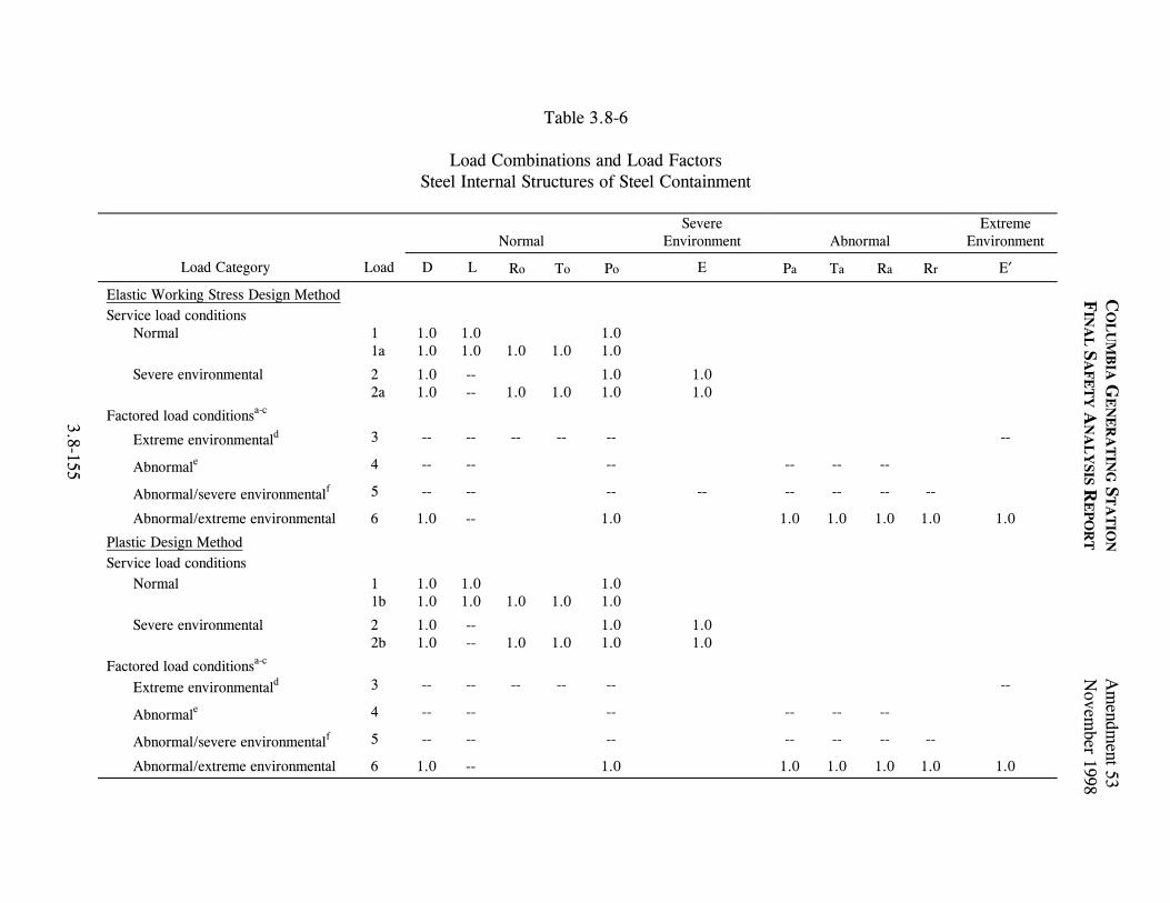
Table 3.8-6
Load Combinations and Load Factors Steel Internal Structures of Steel Containment
C
OL
UM
BIA
GE
NE
RA
TIN
G S
TA
TIO
N A
mendm
ent 53
FIN
AL
SA
FE
TY
AN
AL
YSIS R
EP
OR
T
Novem
ber 1998
3.8-155
Normal
Severe Environment
Abnormal
Extreme Environment
Load Category Load D L Ro To Po E Pa Ta Ra Rr E′
Elastic Working Stress Design Method Service load conditions
Normal 1 1a
1.01.0
1.01.0
1.0
1.0
1.0 1.0
Severe environmental 2 2a
1.01.0
-- --
1.0
1.0
1.0 1.0
1.0 1.0
Factored load conditionsa-c
Extreme environmentald 3 -- -- -- -- -- --
Abnormale 4 -- -- -- -- -- --
Abnormal/severe environmentalf 5 -- -- -- -- -- -- -- --
Abnormal/extreme environmental 6 1.0 -- 1.0 1.0 1.0 1.0 1.0 1.0
Plastic Design Method Service load conditions
Normal 1 1b
1.01.0
1.01.0
1.0
1.0
1.0 1.0
Severe environmental 2 2b
1.01.0
-- --
1.0
1.0
1.0 1.0
1.0 1.0
Factored load conditionsa-c Extreme environmentald 3 -- -- -- -- -- --
Abnormale 4 -- -- -- -- -- --
Abnormal/severe environmentalf 5 -- -- -- -- -- -- --
Abnormal/extreme environmental 6 1.0 -- 1.0 1.0 1.0 1.0 1.0 1.0

Table 3.8-6
Load Combinations and Load Factors Steel Internal Structures of Steel Containment (Continued)
C
OL
UM
BIA
GE
NE
RA
TIN
G S
TA
TIO
N A
mendm
ent 53
FIN
AL
SA
FE
TY
AN
AL
YSIS R
EP
OR
T
Novem
ber 1998
3.8-156
a In combination 6, the maximum values of Pa, Ta, Ra, Yj, Yr, and Ym, including an appropriate dynamic load factor, are used unless a time-history analysis performed to justify otherwise (Rr includes Yj, Yr, and Ym). b When considering Yj, Yr, and Ym, local section strength capacities may be exceeded under these concentrated loads provided there will be no loss of function of any safety-related system. c Thermal loads for factored load conditions are neglected when it can be shown that they are secondary and self-limiting in nature. d Extreme environmental E′ is considered with DBA as in load combination 6. e Abnormal: DBA not considered alone. DBA is considered with E′ as in load combination 6. f Abnormal/severe environmental: DBA with E not considered. DBA is considered with E′ as in load combination 6. NOTE: The drywell floor support steel is considered a steel internal structure in the suppression chamber. All the loads listed are not necessarily applicable to all steel structures. Loads not applicable to a particular structure are deleted. If, for any load combination, the effect of any load other than D reduces the stress, it is deleted from the combination. Combination numbers correspond to those in NUREG-0800, Standard Review Plan, for Section 3.8.3. Dashed lines indicate that the load or load combination is not used. For load definitions, see Section 3.8.3.3.

COLUMBIA GENERATING STATION Amendment 53 FINAL SAFETY ANALYSIS REPORT November 1998 Table 3.8-7 Section Strength Limits and Section Modulus for Structural Steel Internal Structures of Steel Containment
3.8-157
Load Category
Load
Strength Limita,b
Section Modulus of Steel Shapes
Elastic Working Stress Design Method Service load conditions
Normal 1 1a
S 1.5S
Elastic Elastic
Severe environmental 2 2a
S 1.5S
Elastic Elastic
Factored load conditions Extreme environmental 3 1.6S Elastic
Abnormal 4 1.6S Elastic
Abnormal/severe environmental 5 1.6S Plasticc
Abnormal/extreme environmental 6 1.7S Plasticc
Plastic Design Method Service load conditions
Normal 1 1b
Y Y
Plastic Plastic
Severe environmental 2 2b
Y Y
Plastic Plastic
Factored load conditions Extreme environmental 3 0.9Y Plastic
Abnormal 4 0.9Y Plastic
Abnormal/severe environmental 5 0.9Y Plastic
Abnormal/extreme environmental 6 0.9Y Plastic a S is the required section strength based on the elastic design methods and the allowable stresses defined in Part 1 of the AISC Specification for the Design, Fabrication, and Erection of Structural Steel for Buildings, February 12, 1969. b Y is the section strength required to resist design loads based on plastic design methods in Part 2 of the AISC Specification for the Design, Fabrication, and Erection of Structural Steel for Buildings, February 12, 1969. c Plastic section modulus may be used.

Table 3.8-8
Radwaste and Control Building Quality Class and Design Bases Criteria
C
OL
UM
BIA
GE
NE
RA
TIN
G S
TA
TIO
N A
mendm
ent 53
FIN
AL
SA
FE
TY
AN
AL
YSIS R
EP
OR
T
Novem
ber 1998
3.8-158
Environmental Disturbances
Location Materials of Constructiona
Quality Class
Seismic Category
Design Basis Wind
Design Basis Tornado
Tornado-Generated Missiles
Those portions of the radwaste and control building that house systems or components necessary for safe shutdown of the reactor
Reinforced-concrete I I Yes Yes Yes
Those portions of the radwaste building that house equipment containing significant quantities of radioactive material
Reinforced-concrete I I Yes Yes Yes
Other portions Structural steel II II Yes Nob Nob
a See Figure 3.8-42. b “Other portions” denote those portions of the radwaste and control building which are not required to withstand the effects of the design basis tornado and tornado-generated missiles.

Table 3.8-9
Load Combinations and Load Factors Seismic Category I and Nonseismic Category I Safety-Related
Concrete Structures Outside Primary Metal Containment
C
OL
UM
BIA
GE
NE
RA
TIN
G S
TA
TIO
N A
mendm
ent 53
FIN
AL
SA
FE
TY
AN
AL
YSIS R
EP
OR
T
Novem
ber 1998
3.8-159
Normal
Severe Environmental
Abnormal Extreme
Environmental
Load Category ACI 318-71 Strength Design Method
Load
D L Ro To Po Pt Tt F Q E W H F* Q* Pa Ta Ra Rr P′ E′ W′ H′
Service load conditions Construction U1
U2 1.4 0.9
1.3
0.9
1.3
1.3
Normal 1 1b U3 U4 U5 U6
1.4 1.4 1.4 1.4 0.9 0.9
1.7 1.7 1.7 1.7
1.4
1.4
1.4
1.4
1.71.71.71.7
1.41.41.41.4
1.71.71.71.7
Severe 2 2b 2b′ 3 3b 3b′ U7 U8 U9 U10
1.4 1.4 0.9 1.1 1.1 0.9 1.1 1.1 1.4 1.4
1.7 1.4
1.3 1.3
1.3 1.3 1.7 1.4
1.4
1.1
1.4
1.1
1.1
1.4
1.71.4
1.31.3
1.31.31.71.4
1.11.1
1.31.3
1.91.41.4
1.91.4
1.31.31.31.31.3
1.41.4
1.71.4
Factored load conditionsa, b
Extreme environmental 4 5
1.0 --
1.0 --
1.0--
1.0--
1.0 --
Abnormal 6 1.0 1.0 1.5 1.0 1.0
Abnormal/severe environmental
7 1.0 1.0 1.25
1.25 1.0 1.0 1.0
Abnormal/extreme environmental
8 1.0 1.0 1.0 1.0 1.0 1.0 1.0
U11 1.0 1.0 1.0 1.0 1.0 1.0 1.0 1.0 1.0 1.0 1.0 1.0

Table 3.8-9
Load Combinations And Load Factors Seismic Category I and Nonseismic Category I Safety-Related
Concrete Structures Outside Primary Metal Containment (Continued)
C
OL
UM
BIA
GE
NE
RA
TIN
G S
TA
TIO
N A
mendm
ent 53
FIN
AL
SA
FE
TY
AN
AL
YSIS R
EP
OR
T
Novem
ber 1998
3.8-160
a In combinations 6, 7, and 8, the maximum values of Pa, Ta, Ra, Yr, and Yj, including an appropriate dynamic load factor, are used. The value of Ym is arrived at by an energy balance method of structural action (Section 3.6.1.6.3.2), to account for the dynamic nature of the load.
In combinations 7 and 8, local stresses due to concentrated load Yr,, Yj, and Ym may be permitted to exceed the allowable stresses, provided there is no loss of function of any safety-related system as a result thereof. b In considering the concentrated tornado missile load in combination U11, local section strength capacities may be exceeded under these concentrated loads provided there is no loss of function of any safety-related system as a result thereof. NOTES: All the loads listed are not necessarily applicable to all concrete structures. Loads not applicable to a particular structure are deleted. If, for any combination, the effect of any load other than dead loads reduces the stress it is deleted from the combination. Combinations 1 through 8, 1b, 2b, 2b′, 3b, and 3b′ correspond to those in NUREG-0800, Standard Review Plan for Section 3.8.4. Combinations U1 through U11 are not in the review plan for Section 3.8.4 and are used in addition to those of the review plan combinations. Dashed lines indicate that the load or load combination is not used. For load definitions, see Section 3.8.4.3. Combinations 6, 7, and 8 are used only when abnormal loads generated by a postulated pipe break are included.

Table 3.8-10
Load Combinations and Load Factors Seismic Category I and Nonseismic Category I Safety-Related
Steel Structures Outside Primary Metal Containment
Normal
Severe Environmental
Abnormal
Extreme Environmental
Load Category Load D L Ro To Po E W Pa Ta Ra Rr P′ E′ W′
C
OL
UM
BIA
GE
NE
RA
TIN
G S
TA
TIO
N A
mendm
ent 53
FIN
AL
SA
FE
TY
AN
AL
YSIS R
EP
OR
T
Novem
ber 1998
3.8-161
Elastic Working Stress Design Method Service Load Conditions
Normal 1 1a
1.0 ---
1.0 ---
---
---
1.0
Severe environmental 2 2a 3 3a
1.0 --- 1.0 ---
--- --- --- ---
--- ---
--- ---
1.0 1.0
1.0 ---
1.0 ---
Factored Load Conditions
Extreme environmental 4 5
--- ---
--- ---
--- ---
--- ---
--- ---
Abnormal 6 U12
--- 1.0
--- 1.0
--- --- --- 1.0
Abnormal/severe environmental 7 --- --- --- --- --- --- ---
Abnormal/extreme environmental 8 U13U14
--- 1.0 1.0
--- --- --- --- --- 1.01.0
--- 1.0
1.0

Table 3.8-10
Load Combinations and Load Factors Seismic Category I and Nonseismic Category I Safety-Related
Steel Structures Outside Primary Metal Containment (Continued)
Normal
Severe Environmental
Abnormal
Extreme Environmental
Load Category Load D L Ro To Po E W Pa Ta Ra Rr P′ E′ W′
C
OL
UM
BIA
GE
NE
RA
TIN
G S
TA
TIO
N A
mendm
ent 53
FIN
AL
SA
FE
TY
AN
AL
YSIS R
EP
OR
T
Novem
ber 1998
3.8-162
Plastic Design Method Service load conditions
Normal 1 1b
1.0 ---
1.0 ---
---
---
1.0
Severe environmental 2 2b 3 3b
1.0 --- 1.0 ---
--- --- --- ---
--- ---
--- ---
1.0 1.0
1.0 ---
1.0 ---
Factored load conditions
Extreme environmental 4 5
--- ---
--- ---
--- ---
--- ---
--- ---
Abnormal 6 U12
1.0 1.0
1.0 1.0
1.5 1.0 1.0 1.0
Abnormal/severe environmental 7 1.0 1.0 1.25 1.25 1.0 1.0 1.0
Abnormal/extreme environmental 8 U13U14
1.0 1.0 1.0
1.0 1.0 1.0 1.0 1.0 1.01.0
1.0 1.0
1.0

Table 3.8-10
Load Combinations and Load Factors Seismic Category I and Nonseismic Category I Safety-Related
Steel Structures Outside Primary Metal Containment (Continued)
C
OL
UM
BIA
GE
NE
RA
TIN
G S
TA
TIO
N A
mendm
ent 53
FIN
AL
SA
FE
TY
AN
AL
YSIS R
EP
OR
T
Novem
ber 1998
3.8-163
Notes:
1. In combinations 6, 7, and 8, (factored load conditions, Plastic Design Method), the maximum values of Pa, Ta, Ra, Yj, and Yr, including an
appropriate dynamic load factor, are used; and the value of Ym is arrived at by an energy balance method of structural action (Section 3.6.1.6.3.2), to account for the dynamic nature of the load.
In combinations 7 and 8, (factored load conditions, Plastic Design Method), local stresses due to concentrated loads Yr, Yj, and Ym may be permitted to exceed the allowable stresses, provided there is no loss of function of any safety-related system as a result thereof.
In considering the concentrated tornado missile load in combination U14, local section strength capacities may be exceeded under these concentrated
loads provided there is no loss of function of any safety-related system as a result thereof. 2. Thermal loads for factored load conditions are neglected when it can be shown that they are secondary and self-limiting in nature. 3. All the loads listed are not necessarily applicable to all concrete structures. Loads not applicable to a particular structure are deleted. 4. If, for any load combination, the effect of any load other than D reduces the stress, it is deleted from the combination. 5. Combinations 1 through 8, 1a, 2a, 3a, 1b, 2b, and 3b correspond to those in the NRC Standard Review Plan for Section 3.8.4. Combinations U12,
U13, and U14 are not in the review plan for Section 3.8.4, and are used in addition to those of the review plan combinations. 6. Dashed lines indicate that the load or load combination is not used. 7. For load definitions, see Section 3.8.4.3. 8. This table applies to Section 3.8.4. 9. Combinations 6, 7, and 8 in the Plastic Design Method are used only when abnormal loads generated by a postulated pipe break are included.

COLUMBIA GENERATING STATION Amendment 53 FINAL SAFETY ANALYSIS REPORT November 1998 Table 3.8-11 Seismic Category I and Nonseismic Safety-Related Steel Structures Outside Primary Metal Containment
Load Category
Load
Strength Limita, b
Section Modulus of Steel Shapes
3.8-164
Elastic Working Stress Design Method Service load conditions
Normal 1 1a
S 1.5S
Elastic Elastic
Severe environmental 2 2a 3 3a
S 1.5S S 1.5S
Elastic Elastic Elastic Elastic
Factored load conditions Extreme environmental 4
5 1.6S 1.6S
Elastic Elastic
Abnormal 6 U12
1.6S 1.6S
Elastic Elastic
Abnormal/severe environmental 7 1.6S Plasticc
Abnormal/extreme environmental 8 U13 U14
1.7S 1.7S 1.7S
Plasticc
Elastic Elastic
Plastic Design Method Service load conditions
Normal 1 1b
Y Y
Plastic Plastic
Severe environmental 2 2b 3 3b
Y Y Y Y
Plastic Plastic Plastic Plastic
Factored load conditions Extreme environmental 4
5 0.9Y 0.9Y
Plastic Plastic
Abnormal 6 U12
0.9Y 0.9Y
Plastic Plastic

COLUMBIA GENERATING STATION Amendment 53 FINAL SAFETY ANALYSIS REPORT November 1998 Table 3.8-11 Seismic Category I and Nonseismic Safety-Related Steel Structures Outside Primary Metal Containment (Continued)
Load Category
Load
Strength Limita, b
Section Modulus of Steel Shapes
3.8-165
Abnormal/severe environmental 7 0.9Y Plastic
Abnormal/extreme environmental 8 U13 U14
0.9Y 0.9Y 0.9Y
Plastic Plastic Plastic
a S is the required section strength based on the elastic design methods and the allowable stresses defined in Part 1 of the AISC Specification for the Design, Fabrication, and Erection of Structural Steel for Buildings, February 12, 1969. b Y is the section strength required to resist design loads and based on plastic design methods described in Part 2 of the AISC Specification for the Design, Fabrication, and Erection of Structural Steel for Buildings, February 12, 1969. c Plastic section modulus may be used.

Table 3.8-12
Maximum Permissible Stresses Seismic Category I and Nonseismic Category I Safety-Related Reinforced-Concrete Structures
C
OL
UM
BIA
GE
NE
RA
TIN
G S
TA
TIO
N A
mendm
ent 53
FIN
AL
SA
FE
TY
AN
AL
YSIS R
EP
OR
T
Novem
ber 1998
3.8-166
Concrete Reinforcing Steel Shear
Loading Conditions
Flexural and Axial Compression
Flexural
Punching Flexural Tension
Shear Tension
Axial Compression
Service load and factored load conditions
φ (0.85 f′c) Varies from: 0.70(0.85f′c) = 0.60f′c to 0.90(0.85f′c) = 0.76f′c
2 ′f c 4 ′f c 0.9fy 0.85fy Varies from 0.7fy to 0.75fy
Notes: 1. Concrete tensile strength is not relied upon. 2. f′c = 4000 psi; η = 8 3. fy = 40,000 psi for reinforcing steel up to and including #5 bar size. 4. fy = 60,000 psi for reinforcing steel over #5 bar size. 5. The maximum permissible compression and flexural stress of 0.85f′c corresponds to a limiting strain of 0.003 in./in. 6. The symbol φ represents the capacity reduction factor. 7. Normal permissible bearing stresses are as specified in ACI 318-71. 8. This table applies to the Sections 3.8.3, 3.8.4, and 3.8.5.

COLUMBIA GENERATING STATION Amendment 53 FINAL SAFETY ANALYSIS REPORT November 1998
3.8-167
Table 3.8-13 Primary Containment Vessel Electrical Penetrations Principal Design Parameters
Environmental Conditiona
Inside Primary Containment Vessel
Outside Primary Containment Vessel
Normal operating pressure -0.5 psig to 2 psig -0.10 in. to -1.0 in. water gauge
Design pressure -2.0 psig to 45 psig 7 in. water gauge
Test pressure 52 psig N/A
Normal operating temperature 135°F average 150°F maximum
70°F average 104°F maximum
Design temperature (accident - 6 hr) 340°F 212°F
Design temperature (accident up to 6 months)
250°F 150°F
Relative humidity (normal) 40% to 55% 90% maximum
40%
Relative humidity (LOCA) 100% 100%
Gamma radiation (normal operating) 50.0 rad/hr N/A
Neutron radiation (normal operating) 1.4 x 10⁵ neutrons/cm2 sec N/A
Lowest service metal temperature 30°F N/A
Integrated dose - gamma (normal condition)
1.8 x 10⁷ rad N/A
Integrated dose - neutron (normal condition)
1.8 x 10¹⁴ neutrons/cm2 N/A
Integrated dose - gamma (accident conditions)
2.6 x 10⁷ rad N/A
LOCA dose rate - gammab 1.3 x 10⁶ rad N/A
a Under normal operating and accident conditions, the design parameters are integrated over 40 years. b LOCA analysis is based on the assumption that 100% of the noble gases, 50% of the halogens, and 1% of the solid fission products are released from the core.

COLUMBIA GENERATING STATION Amendment 53 FINAL SAFETY ANALYSIS REPORT November 1998
3.8-168
Table 3.8-14 Primary Containment Vessel Piping Penetrations Principal Design
Parameters Characteristics
Pressure suppression chamber Internal design pressure 45 psig
External design pressure (due to negative internal pressure) 2.0 psig
Drywell Internal design pressure 45 psig
External design pressure (due to negative internal pressure) 2.0 psig
Design temperature of drywell 340°F
Design temperature of pressure suppression chamber 275°F
Normal operating temperature - suppression chamber air space 95°Fa
150°F (maximum)b
Normal operating temperature - drywell 135°Fa
Normal operating pressure - drywell and suppression chamber 0 psig to 2 psig
a Average or bulk temperature. b Average of two thermocouples located near ceiling.

990578.73 3.8-9FigureForm No. 960690
Draw. No. Rev.
Amendment 54April 2000
DELETED
Columbia Generating StationFinal Safety Analysis Report

Amendment 57 December 2003
CoIumbia Generating Station Final Safety Analysis Report
Personnel Access Airlock - Typical Bulkhead Mechanical Penetration
Draw. No. 020552.10 Rev. Figure 3.8-14

Amendment 55May 2001
Personnel Access Airlock Typical BulkheadMechanical Penetration Seal
910402.19 3.8-15FigureForm No. 960690
Draw. No. Rev.
Notes:
1. Each shaft penetrating the containment bulkhead or theatmosphere bulkhead is sealed with a cartridge type seal unithaving double dynamic seals. A test connection is providedfor pressure testing between the seals.
2. See Figure 3.8-14 for additional views and details of thisseal in a typical bulkhead mechanical penetration.
Key
61626364656667686970
Description
Seal Housing Retaining RingSeal Housing SleeveBronze Bushing CartridgeLocking Set ScrewShaftOutboard Quad SealInboard Quad SealCartridge O-Ring SealsHousing O-Ring SealSeal Test Connection
Section through Bulkhead Penetration Seal
64
69
61
63
65
67
62
66
70
68
Columbia Generating StationFinal Safety Analysis Report

Amendment 57December 2003
Personnel Access Airlock - Typical BulkheadElectrical Penetration
990578.92 3.8-16FigureForm No. 960690
Draw. No. Rev.
Note:The locations of the Conax fittings areindicated on Figures 3.8-11 & 3.8-12
Large Hex
Small Hex
1/8" x 45°Chamfer (NoSharp Edges)
Instructions Followed for InstallingConax Fittings (P1 thru P4)
1) Install the Conax fitting into the bulkhead and pressure seal the leads before electrical boxes are fastened in place.2) Use only the small hex for installing the Conax fitting into the bulkhead.3) Use the larger hex for pressure sealing the leads.4) Caution: Inside parts of the Conax fittings are easily lost. Do not take fitting apart.5) Conax fittings to be installed from the pressure side only which means Conax fittings to be installed on the side of the bulkhead which the door hinges on.
LDCN-02-000
Columbia Generating StationFinal Safety Analysis Report

1' -
0 1/
4"
Amendment 55May 2001
Primary Containment Vessel Drywell FloorDowncomer Vent Pipes
990306.73 3.8-19FigureForm No. 960690
Draw. No. Rev.
3' - 1"
DOWNCOMER
W33
2"
Downcomer SupportAnd Seal Plate Ring
Drywell Floor
1' 2
"DowncomerOpen End W12
3 1/2" Grating
El. 499' - 6"
Deflector Web Plates
Jet Detector
4"
El. 501' - 0"
El. 497' - 6"
ErectionL4 x 4 x 1/4
1 1/
4"1/
2"
Det
ecto
r1'
0"
Columbia Generating StationFinal Safety Analysis Report

Amendment 55May 2001
Primary Containment Vessel PenetrationAssembly - Type 1 Pipe
990306.74 3.8-54FigureForm No. 960690
Draw. No. Rev.
C L
W.P.#1
FieldWeld
Biological Shield Wall
Pene
tratio
n
Steel PipeSleeve Penetration
Nozzle
Penetration Insert
Inside Face of PrimaryContainment Vessel
Support Shoe(when Req'd)
Guides whenRequired
Isolation Valve
W.P.#3
Lateral ResistantAssembly (whenrequired)
W.P.#2
Field Weld(Typical)
ProcessPipe
Flued HeadFitting
Insulation (whenRequired)
Guard Pipe, when Required
Clearance
Columbia Generating StationFinal Safety Analysis Report

Amendment 55May 2001
Primary Containment Vessel PenetrationAssembly - Types 2 and 3 Pipe
990306.75 3.8-55FigureForm No. 960690
Draw. No. Rev.
C LPe
netra
tion
W.P.#1
FieldWeld
Biological Shield Wall Steel PipeSleeve
PenetrationNozzle andProcess Pipe
ClearancePenetration Insert
Inside Face of PrimaryContainment Vessel
NOTE:Type 3 Spare penetrations which areidentified as spare penetrations in in Fig.3.8-51 are provided with closure plates atW.P.#2 location. Type 3 penetrations whichare not spare penetrations as indicated inFig. 3.8-51, are not provided withpermanent closure plates.
Field Weld
Process Pipefor Type 2Only
Isolation Valve(Type 2 Only) SeeDetail Below forType 3.
Closure Plate forType 3 SparePenetrations. SeeNote Below
Field Weld
Field Weld forType 2 Only
C LPe
netra
tion
W.P.#2
Columbia Generating StationFinal Safety Analysis Report

Amendment 55May 2001
Primary Containment Vessel PenetrationAssembly - Type 4 Electrical Canister Type
990306.76 3.8-56FigureForm No. 960690
Draw. No. Rev.
Pene
tratio
n
W.P.#1
Field Weld(Typical)
Biological Shield Wall Steel PipeSleeve
PenetrationNozzle
Clearance
Penetration Insert
Inside Face of PrimaryContainment Vessel
This line is normally capped.Gage and valve are part ofthe local leak rate testing.
Valve & Pressure Gage
RemovableEnd Cover(both ends)
Shield MountingStuds
Shield for RadiationProtection whereRequired
Junction BoxMounting Flange
Stress Cone
Removable Type NEMA 4Junction Box (both ends)
Weld Ring (both ends)
*
*
Bushing
OutboardHeader
Inboard Header
Cannister
Columbia Generating StationFinal Safety Analysis Report
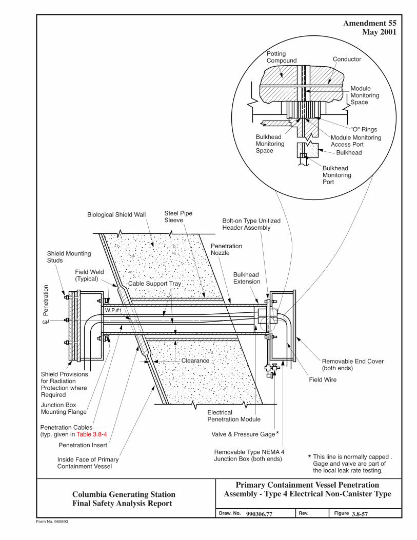
Amendment 55May 2001
Primary Containment Vessel PenetrationAssembly - Type 4 Electrical Non-Canister Type
990306.77 3.8-57FigureForm No. 960690
Draw. No. Rev.
C L
W.P.#1
Field Weld(Typical)
Biological Shield Wall
Pene
tratio
n
Steel PipeSleeve
PenetrationNozzle
Clearance
Penetration Insert
Inside Face of PrimaryContainment Vessel
This line is normally capped .Gage and valve are part ofthe local leak rate testing.
ElectricalPenetration Module
Valve & Pressure Gage
Removable End Cover(both ends)
Shield MountingStuds
Shield Provisionsfor RadiationProtection whereRequiredJunction BoxMounting Flange
Penetration Cables(typ. given in Table 3.8-4
Field Wire
Removable Type NEMA 4Junction Box (both ends)
Cable Support Tray
Bolt-on Type UnitizedHeader Assembly
BulkheadExtension
*
*
PottingCompound Conductor
ModuleMonitoringSpace
"O" Rings
BulkheadMonitoringPort
Bulkhead
Module MonitoringAccess Port
BulkheadMonitoringSpace
Columbia Generating StationFinal Safety Analysis Report

Amendment 55May 2001
Primary Containment Vessel Penetration Assembly- Types 5, 6, And 7 Instrumentation
990306.78 3.8-58FigureForm No. 960690
Draw. No. Rev.
C LPe
netra
tion
W.P.#1
Plate Welded at 4 Places
Field Weld
Biological Shield Wall
Steel Pipe Sleeve
(Sloping) Penetration Nozzle
Plate
1" dia. StainlessSteel Pipe (Typical)
Closure Plate(Typical)
Welded All Around
ClearancePenetration Insert
Inside Face of PrimaryContainment Vessel
Columbia Generating StationFinal Safety Analysis Report

Amendment 55May 2001
Primary Containment Vessel SuppressionChamber Access Hatch
95-8.361.621010 FigureForm No. 960690
.veR.oN .warD
4'-1
0" A
rc M
eas.
On
42'-1
0 1/
2" R
adiu
s
EL. 4
73'-4
"
EL. 4
73'-6
"
Pene
tratio
n X-
51
Pene
tratio
n In
sert
Insi
de F
ace
of P
rimar
yC
onta
inm
ent V
esse
l
Top
OG
Gra
ting
EL. 4
72'-4
"
Stee
l Pla
tform
Cle
aran
ceFi
eld
Wel
d Al
l Aro
und
Pipe
Sle
eve
Rea
ctor
Bld
g.Fl
oor S
lab
EL. 4
71'-0
"Yo
ke B
olt
Hor
izon
tal
Hin
ge B
olt N
ut
42" O
.D.
600#
"Tub
e Tu
rn" D
oubl
e Bo
ltH
oriz
onta
l Hin
ged
Clo
sure
600
H 4
1" I.
D. S
uita
ble
for 4
5 P.
S.I.
@27
5°F
Furn
ishe
d w
ith D
oubl
e "O
" Rin
g "B
una
N" S
eal w
ith S
pace
Bet
wee
n Se
als
Biol
ogic
al S
hiel
d W
all
R= 3'-0
"
R= 1'-8
1/2"
2'-2
3/4
"
1'-1
3/8
"
C L
Verti
cal
C A
zim
uth
155°
L
1/2"
Columbia Generating StationFinal Safety Analysis Report

Amendment 53 November 1998
Columbia Generating Station Final Safety Analysis Report
Primary Containment Vessel Radial Beam Framing Systems
Draw. No. 020552.12 Rev. Figure 3.8-61

Amendment 55May 2001
Underground Pipe Penetration Flexible Watertight Closure Boot
26-8.302.621010 FigureForm No. 960690
.veR.oN .warD
C LPi
pe S
leev
ean
d Pi
pe
O.D. WallSleeve
NOM. PipeSize
For B
oot M
ater
ial a
nd
Addi
tiona
l Det
ails
Not
Sho
wn
See
Figu
re 3
.8-5
0
As S
how
n fo
r Spl
it C
asin
g Pi
pe. W
here
Cas
ting
is N
otU
sed,
Bon
d Bo
ot M
ater
ial
Dire
ctly
to P
ipe
Willi
amso
nU
-Sea
l
3" Min
.12
" to
24" M
ax.
6"6"
to 1
2" 2 3/
4'2
3/4'
3"
1 1/
2"
3" Min
.
Columbia Generating StationFinal Safety Analysis Report

COLUMBIA GENERATING STATION Amendment 53 FINAL SAFETY ANALYSIS REPORT November 1998
3.9-1
3.9 MECHANICAL SYSTEMS AND COMPONENTS 3.9.1 SPECIAL TOPICS FOR MECHANICAL COMPONENTS 3.9.1.1 Design Transients This section shows the transients that are used in the design of the ASME Boiler and Pressure Vessel (B&PV) Code Section III, Class 1, control rod drive (CRD) components, reactor assembly including core supports and reactor internals, main steam, and recirculation systems. The number of cycles or events for each transient is included. The design transients shown in this section are included in the design specifications for the components. Transients or combinations of transients are classified with respect to the component operating condition categories identified as “normal,” “upset,” “emergency,” “faulted,” or “testing” in the ASME Code if applicable. (The first four operating condition categories correspond to Service Levels A, B, C, and D, respectively, which are used in Section III after the Winter 1976 Addenda.) 3.9.1.1.1 Control Rod Drive Transients The normal and test service load cycles used for design purposes for the 40-year life of the CRDs are as follows:
Transient Category Cycles a. Reactor startup/shutdown Normal/upset 120 b. Vessel pressure tests Normal/upset 130 c. Vessel overpressure Normal/upset 10 d. Scram test plus startup scrams Normal/upset 300 e. Operational scrams Normal/upset 300 f. Jog cycles Normal/upset 30,000 g. Shim/drive cycles Normal/upset 1000
In addition to the above cycles, the following have been considered in the design of the CRD.
h. Scram with inoperative buffer Normal/upset 10

COLUMBIA GENERATING STATION Amendment 53 FINAL SAFETY ANALYSIS REPORT November 1998
3.9-2
i. Scram with stuck control Normal/upset 1 blade faulted j. Operating Basis Earthquake Normal/upset 10 (OBE)*
k. Safe Shutdown Earthquake Faulted 1 (SSE)**
All ASME Class 1 components of the CRD have been analyzed according to ASME Code Section III. The capability of the CRDs to withstand emergency and faulted conditions is verified by test rather than analysis. 3.9.1.1.2 Control Rod Drive Housing and In-Core Housing Transients The number of transients, their cycles, and classification as considered in the design and fatigue analysis of the CRD housing and in-core housing are as follows:
Transient Category Cycles a. Normal startup and shutdown Normal/upset 120 b. Vessel pressure tests Normal/upset 130 c. Vessel overpressure tests Normal/upset 10 d. Interruption of feedwater flow Normal/upset 80 e. Scram Normal/upset 200 f. OBE Normal/upset 10 g. SSE Faulted 1
* The frequency of occurrence of this transient would indicate emergency category. However, for conservatism, the OBE condition was analyzed as an upset condition. Ten peak OBE cycles are postulated. ** SSE is a faulted condition; however, in the stress analysis, it was treated as emergency with lower stress limits.

COLUMBIA GENERATING STATION Amendment 53 FINAL SAFETY ANALYSIS REPORT November 1998
3.9-3
CRD Housing Only
h. Stuck rod scram Normal/upset 1 i. Scram no buffer Normal/upset 10
3.9.1.1.3 Hydraulic Control Unit Transients The normal and test service load cycles used in the original design and fatigue analysis for the 40-year life of the hydraulic control unit (HCU) are as follows:
Transient Category Cycles a. Normal startup and shutdown Normal/upset 120 b. Vessel pressure tests Normal/upset 130 c. Vessel overpressure tests Normal/upset 10 d. Scram tests (cold) Normal/upset 300 e. Operational scrams (hot) Normal/upset 300 f. Jog cycles Normal/upset 30,000 g. Drive cycles Normal/upset 1000 h. Scram with stuck scram Normal/upset 1 discharge valve i. OBE Normal/upset 10 j. SSE faulted 1
3.9.1.1.4 Core Support and Reactor Internals Transients The normal and test service load cycles used for the design and fatigue analysis for the 40-year life of the core support and reactor internals are shown in Table 3.9-1. 3.9.1.1.5 Nuclear Steam Supply System Scope Main Steam System Transients The following transients are considered in the stress analysis of the main steam piping between the reactor pressure vessel (RPV) and the outer containment isolation valve:
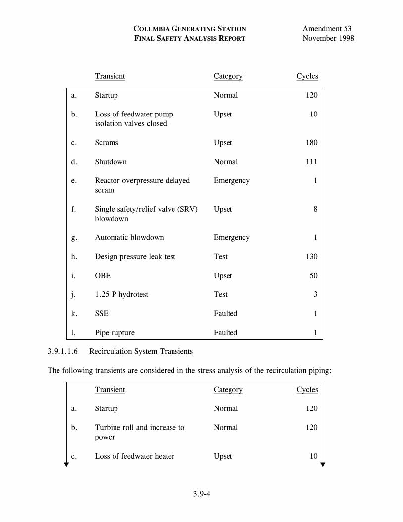
COLUMBIA GENERATING STATION Amendment 53 FINAL SAFETY ANALYSIS REPORT November 1998
3.9-4
Transient Category Cycles
a. Startup Normal 120 b. Loss of feedwater pump Upset 10 isolation valves closed c. Scrams Upset 180 d. Shutdown Normal 111 e. Reactor overpressure delayed Emergency 1 scram f. Single safety/relief valve (SRV) Upset 8 blowdown g. Automatic blowdown Emergency 1 h. Design pressure leak test Test 130 i. OBE Upset 50 j. 1.25 P hydrotest Test 3 k. SSE Faulted 1 l. Pipe rupture Faulted 1
3.9.1.1.6 Recirculation System Transients The following transients are considered in the stress analysis of the recirculation piping:
Transient Category Cycles a. Startup Normal 120 b. Turbine roll and increase to Normal 120 power c. Loss of feedwater heater Upset 10

COLUMBIA GENERATING STATION Amendment 53 FINAL SAFETY ANALYSIS REPORT November 1998
3.9-5
d. Partial feedwater heater bypass Upset 70 e. Scrams Upset 180 f. Shutdown Normal 111 g. Loss of feedwater pump Upset 10 isolation valves closed h. Reactor overpressure with Emergency 1 delayed scram i. Single SRV blowdown Upset 8 j. Automatic blowdown Emergency 1 k. Design pressure leak test Test 130 l. OBE Upset 50 m. 1.25 P hydrotest Test 3 n. SSE Faulted 1 o. Pipe rupture Faulted 1
3.9.1.1.7 Reactor Assembly Transients The reactor assembly includes the RPV, support skirt, and shroud support. The cycles listed in Table 3.9-1 were specified in the reactor assembly design and fatigue analysis. 3.9.1.1.8 Main Steam Isolation Valve Transients The main steam isolation valves (MSIV) are designed for the following service conditions and thermal cycles:
Transient Category Cycles a. Preoperational at 100°F Normal/upset 150 b. Startup (heating 100°F) Normal/upset 120

COLUMBIA GENERATING STATION Amendment 53 FINAL SAFETY ANALYSIS REPORT November 1998
3.9-6
c. Shutdown
Transient Category Cycles
1. Cooling cycles Normal/upset 120 at 100°F/hr 540°F to 375°F
2. Cooling cycles Normal/upset 120
at 270°F/hr 375°F to 330°F
3. Cooling cycles Normal/upset 120
at 100°F/hr 330°F to 100°F
d. Scram cooling cycles Normal/upset 180 at 100°F/hr e. Emergency and faulted transients
1. 546°F to 281°F in 15 sec Emergency/faulted 1 2. 546°F to 375°F Emergency/faulted 1 in 3.3 minutes 375°F to 281°F Emergency/faulted 1 at 300°F/hr 3. 546°F to 375°F Emergency/faulted 8 in 10 minutes
4. 375°F to 281°F Emergency/faulted 8 at 100°F/hr 5. 546°F to 583°F in 2 sec Emergency/faulted 1
583°F to 538°F Emergency/faulted 1 in 30 sec 538°F to 400°F Emergency/faulted 1 at 100°F/hr
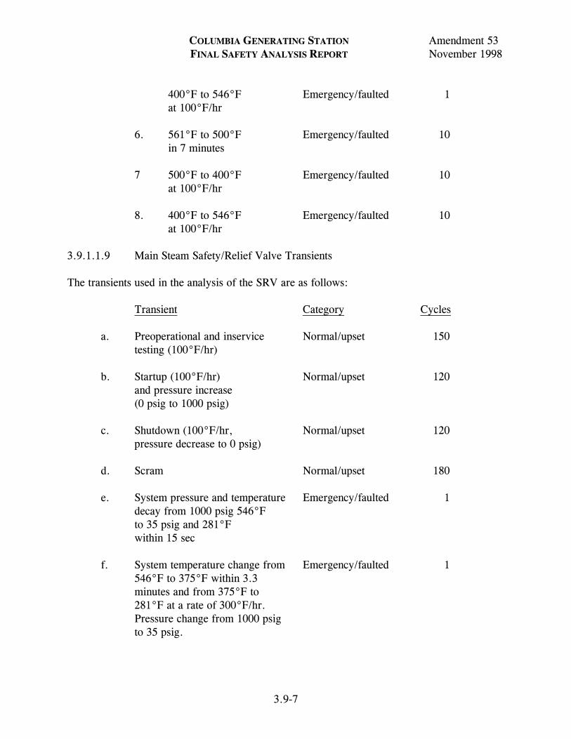
COLUMBIA GENERATING STATION Amendment 53 FINAL SAFETY ANALYSIS REPORT November 1998
3.9-7
400°F to 546°F Emergency/faulted 1 at 100°F/hr
6. 561°F to 500°F Emergency/faulted 10 in 7 minutes
7 500°F to 400°F Emergency/faulted 10 at 100°F/hr 8. 400°F to 546°F Emergency/faulted 10 at 100°F/hr
3.9.1.1.9 Main Steam Safety/Relief Valve Transients The transients used in the analysis of the SRV are as follows:
Transient Category Cycles
a. Preoperational and inservice Normal/upset 150 testing (100°F/hr) b. Startup (100°F/hr) Normal/upset 120 and pressure increase (0 psig to 1000 psig) c. Shutdown (100°F/hr, Normal/upset 120 pressure decrease to 0 psig) d. Scram Normal/upset 180 e. System pressure and temperature Emergency/faulted 1 decay from 1000 psig 546°F to 35 psig and 281°F within 15 sec f. System temperature change from Emergency/faulted 1 546°F to 375°F within 3.3 minutes and from 375°F to 281°F at a rate of 300°F/hr. Pressure change from 1000 psig to 35 psig.

COLUMBIA GENERATING STATION Amendment 53 FINAL SAFETY ANALYSIS REPORT November 1998
3.9-8
g. System temperature change Normal/upset 8 from 546°F to 375°F within 10 minutes and from 375°F to 281°F at a rate of 100°F/hr. Pressure change from 1000 psig to 35 psig.
h. System temperature change Emergency/faulted 1 from 546°F to 583°F within 2 sec, from 583°F to 538°F within 30 sec, and from 538°F to 400°F and return to 546°F at a rate of 100°F/hr. Pressure change from 1000 psig to 1350 psig thence to 240 psig and return to 1000 psig.
i. System temperature changes, Emergency/faulted 10
greater than 30°F, from 561°F to 500°F within 7 minutes and from 500°F to 400°F and return to normal operating temperature of 546°F at a rate of 100°F/hr. Pressure change from 1000 psig to 1180 psig to 240 psig and return to normal operating of 1000 psig.
Paragraph NB-3552 of ASME Code Section III excludes various transients and provides means for combining those which are not excluded. Review and approval of the equipment supplier’s certified calculation provides assurance of proper accounting of the specified transients. 3.9.1.1.10 Recirculation Flow Control Valve Transients The following pressure and temperature transients were considered in the design of the recirculation system flow control valve (this valve has been blocked open):
Transient Category Cycles a. Startup (100°F/hr) heating Normal/upset 300 rate 70°F to design temperature b. Small temperature changes (29°F) Normal/upset 600

COLUMBIA GENERATING STATION Amendment 53 FINAL SAFETY ANALYSIS REPORT November 1998
3.9-9
c. 50°F step changes Normal/upset 200 d. Safety/relief valve blowdowns Normal/upset 30 (single valve) (546°F to 375°F in 10 minutes) e. Safety valve transient Normal/upset 1 (110% of design pressure) f. Installed hydrotests
1. 1300 psig Testing 130 2. 1670 psig Testing 3
g. Automatic blowdown Emergency 2
(546°F to 281°F in 15 sec)
h. Improper start of pump in Emergency 1
cold loop (130°F step to 546°F for 15 sec)
3.9.1.1.11 Recirculation Pump Transients The following transients are listed in the design specification as a requirement for design considerations. However, a submitted certified analysis considering thermal stresses was not required. The vendor was required to submit a certification of compliance. The submitted certified design calculations only considered pressure transient. Nozzle piping loads were considered in accordance with the following ASME paragraph:
“The pump case shall be designed to withstand secondary stresses due to piping reactions in accordance with ASME Code, Section III, 1971.” Transient Category Cycles a. Heatup and cooldown Normal/upset 300 at 100°F/hr b. +29°F temperature changes Normal/upset 600 c. +50°F temperature changes Normal/upset 200

COLUMBIA GENERATING STATION Amendment 53 FINAL SAFETY ANALYSIS REPORT November 1998
3.9-10
d. RPV pressure transients Normal/upset 1
to 110% design pressure e. SRV blowdowns Emergency 8 f. Improper pump startup, Emergency 1
100°F to 552°F in 15 sec g. Cooling transient 552°F to Faulted 1
281°F in 15 sec h. Hydrotest to 1300 psig Testing 130 i. Hydrotest to 1670 psig Testing 3
3.9.1.1.12 Recirculation Gate Valve Transients The following transients are considered in the design of the recirculation gate valves:
Transient Cycles a. 50°F to 575°F at 100°F/hr 300 b. +29°F between limits of 50°F and 600 575°F, instantaneous c. +50°F between limits of 50°F and 200 546°F, instantaneous d. 546°F to 375°F, instantaneous 30 e. 546°F to 281°F, instantaneous 2 f. 130°F to 546°F, instantaneous 1 g. 110% design pressure at 575°F 1 h. 1300 psi at 100°F installed 130 hydrostatic test i. 1670 psi at 100°F installed 3 hydrostatic test

COLUMBIA GENERATING STATION Amendment 53 FINAL SAFETY ANALYSIS REPORT November 1998
3.9-11
3.9.1.1.13 Balance-of-Plant Transients The transients used in design and fatigue analysis of the balance-of-plant (BOP) components are listed in Table 3.9-1 with the exception that 50 maximum stress cycles due to an OBE are used in fatigue evaluations. Table 3.9-1 also shows the thermal cycles which are tracked to provide an indication of reactor cumulative fatigue usage. 3.9.1.2 Nuclear Steam Supply System Computer Programs Used in Original Analysis The following italicized text is historical information provided in the FSAR to support the application for an operating license. As such, it is not subject to change and therefore has not been verified for accuracy or updated during the FSAR upgrade process per 10 CFR 50.71(e). The following sections discuss computer programs used in the analysis of the major safety-related components. (Computer programs were not used in all components; hence not all components are listed.) The nuclear steam supply system (NSSS) programs can be divided into two categories. Vendor Programs The verification of the following two groups of vendor programs is ensured by contractual requirements between GE and the vendor. The quality assurance procedure of these proprietary programs used in the design of N-stamped equipment is in full compliance with 10 CFR 50, Appendix B. CB&I Programs 711 GENOZZ 948 NAPALM 1027 846 781 KALNINS 979 ASFAST 766 TEMAPR 767 PRINCESS 928 TGRV 962E962A 984 992 GASP 1037 DUNHAM’S 1335 1606 and 1657 HAP

COLUMBIA GENERATING STATION Amendment 53 FINAL SAFETY ANALYSIS REPORT November 1998
3.9-12
1635 953 955 MESHPLOT 1028 1038 GE Programs The verification of the following GE programs has been performed in accordance with the requirements of 10 CFR 50, Appendix B. Evidence of the verification of input, output, and methodology is documented in GE Design Record Files. MASS. SNAP (MULTISHELL) HEATER PISYS ANSI7 SAP4G FTFLG01 ANSYS BSTIF01 RTRMEC POSUM BILRD RVFOR TSFOR LUGST PDA DYSEA SPECA SEISM 3.9.1.2.1 Reactor Pressure Vessel and Internals 3.9.1.2.1.1 Reactor Pressure Vessel. CB&I Programs are used to analyze the RPV. Detailed descriptions are provided in Sections 3.9.1.2.1.1.1 through 3.9.1.2.1.1.20. 3.9.1.2.1.1.1 CB&I Program 7-11 - “GENOZZ”. The GENOZZ computer program is used to proportion barrel and double taper type nozzles to comply with the specifications of the ASME Code, Section III and contract documents. The program will either design such a configuration or analyze the configuration input into it. If the input configuration will not comply with the specifications, the program will modify the design and redesign it to yield an acceptable result.

COLUMBIA GENERATING STATION Amendment 53 FINAL SAFETY ANALYSIS REPORT November 1998
3.9-13
3.9.1.2.1.1.2 CB&I Program 9-48 - “NAPALM”. The basis for the program NAPALM, Nozzle Analysis Program-All Loads Mechanical, is to analyze nozzles for mechanical loads and find the maximum stress intensity and location. The program analyzes at specified locations from the point of application of the mechanical loads. At each location the maximum stress intensity is calculated for both the inside and outside surfaces of the nozzle. The program gives the maximum stress intensity for both the inside and outside surfaces of the nozzle, as well as its angular location around the circumference of the nozzle from the 0 reference location. The principal stresses are also printed. The stresses resulting from each component of loading (bending, axial, shear, and torsion) are printed, as well as the loadings which caused these stresses. 3.9.1.2.1.1.3 CB&I Program 1027. This program is a computerized version of the analysis method contained in the “Welding Research Council Bulletin F107, December 1965.” Part of this program provides for the determination of the shell stress intensities (S) at each of four cardinal points at both the upper and lower shell plate surfaces (ordinarily considered outside and inside surfaces) around the perimeter of a loaded attachment on a cylindrical or spherical vessel. With the determination of each S, there is also determined the components of that S (two normal stresses and one shear stress). This program provides the same information as the manual calculation and the input data is essentially the geometry of the vessel and attachment. 3.9.1.2.1.1.4 CB&I Program 846. This program computes the required thickness of a hemispherical head with a large number of circular parallel penetrations by means of the area replacement method in accordance with the ASME Code, Section III. In cases where the penetration has a counterbore, the thickness is determined so that the counterbore does not penetrate the outside surface of the head. 3.9.1.2.1.1.5 CB&I Program 781 - “KALNINS”. This program is a thin elastic shell program for shells of revolution. This program was developed by Dr. A. Kalnins of Lehigh University. Extensive revisions and improvements have been made by Dr. J. Endicott to yield the CB&I version of this program. The basic method of analysis was published by Professor Kalnins in the Journal of Applied Mechanics, Volume 31, September 1964, pages 467 through 476. The KALNINS thin shell program (Program 781) is used to establish the shell influence coefficient and to perform detail stress analysis of the vessel. The stresses and the deformations of the vessel can be computed for any combination of the following axisymmetric loading:

COLUMBIA GENERATING STATION Amendment 53 FINAL SAFETY ANALYSIS REPORT November 1998
3.9-14
a. Preload condition, b. Internal pressure, and c. Thermal load.
3.9.1.2.1.1.6 CB&I Program 979 - “ASFAST”. ASFAST Program (Program 979) performs the stress analysis of axisymmetric, bolted closure flanges between head and cylindrical shell. 3.9.1.2.1.1.7 CB&I Program 766 - “TEMAPR”. This program will reduce any arbitrary temperature gradient through the wall thickness to an equivalent linear gradient. The resulting equivalent gradient will have the same average temperature and the same temperature-moment as the given temperature distribution. Input consists of plant thickness and actual temperature distribution. The output contains the average temperature and total gradient through the wall thickness. The program is written in FORTRAN IV language. 3.9.1.2.1.1.8 CB&I Program 767 - “PRINCESS”. The PRINCESS computer program calculates the maximum alternating stress amplitudes from a series of stress values by the method in Section III of the ASME Pressure Vessel Code. 3.9.1.2.1.1.9 CB&I Program 928 - “TGRV”. The TGRV program is used to calculate temperature distributions in structures or vessels. Although it is primarily a program for solving the heat conduction equations, some provisions have been made for including radiation and convection effects at the surfaces of the vessel. The TGRV program is a greatly modified version of the TIGER heat transfer program written about 1958 at Knolls Atomic Power Laboratory, by A. P. Bray. There have been many versions of TIGER in existence including TIGER II, TIGER II B, TIGER IV, and TIGER V, in addition to TGRV. The program utilizes an electrical network analogy to obtain the temperature distribution of any given system as a function of time. The finite difference representation of the three-dimensional equations of heat transfer are repeatedly solved for small time increments and continually summed. Linear mathematics are used to solve the mesh network for every time interval. Included in the analysis are the three basic forms of heat transfer, conduction, radiation, and convection, as well as internal heat generation. Given any odd-shaped structure, which can be represented by a three-dimensional field, its geometry and physical properties, boundary conditions, and internal heat generation rates, TGRV will calculate and give as output the steady state or transient temperature distributions in the structure as a function of time. 3.9.1.2.1.1.10 CB&I Program 962 - “E0962A”. Program E0962A is one of a group of programs (E0953A, E1606A, E0962A, E0992N, E1037N, and E0984N) which are used

COLUMBIA GENERATING STATION Amendment 53 FINAL SAFETY ANALYSIS REPORT November 1998
3.9-15
together to determine the temperature distribution and stresses in pressure vessel components by the finite element method. Program E0962A is primarily a plotting program. Using the nodal temperatures calculated by program E1606A or Program E0928A, and the node and element cards for the finite element model, it calculates and plots lines of constant temperature (isotherms). These isotherm plots are used as part of the stress report to present the results of the thermal analysis. They are also very useful in determining at which points in time the thermal stresses should be determined. In addition to its plotting capability the program can also determine the temperatures of some of the nodal points by interpolation. This feature of the program is intended primarily for use with the compatible TGRV and finite element models that are generated by program E0953A. 3.9.1.2.1.1.11 CB&I Program 984. Program 984 is used to calculate the stress intensity of the stress differences, on a component level, between two different stress conditions. The calculation of the stress intensity of stress component differences (the range of stress intensity) is required by Section III of the ASME Code. 3.9.1.2.1.1.12 CB&I program 992 - “GASP”. The GASP computer program, originated by Professor E. L. Wilson of the Univeristy of California at Berkeley, uses the finite element method to determine the stresses and displacements of plane or axisymmetric structures of arbitrary geometry and is written in FORTRAN IV. For a detailed account, see Reference 3.9-1. As mentioned above, the program determines the stresses and displacements of plane or axisymmetric structures using the finite element method. The structures may have arbitrary geometry and have linear or non-linear material properties. The loadings may be thermal, mechanical, accelerational, or a combination of these. The structure to be analyzed is broken up into a finite number of discrete elements or “finite-elements” which are interconnected at finite number of “nodal-points” or “nodes.” The actual loads on the structure are simulated by statically equivalent loads acting at the appropriate nodes. The basic input to the program consists of the geometry of the stress-model and the boundary conditions. The program then gives the stress components at the center of each element and the displacements at the nodes, consistent with the prescribed boundary conditions. 3.9.1.2.1.1.13 CB&I Program 1037 - “DUNHAM’S”. DUNHAM’S program is a finite ring element stress analysis program. It will determine the stresses and displacements of axisymmetric structures of arbitrary geometry subjected to either axisymmetric loads or non-axisymmetric loads represented by a Fourier series.

COLUMBIA GENERATING STATION Amendment 53 FINAL SAFETY ANALYSIS REPORT November 1998
3.9-16
This program is similar to the GASP program (CB&I 992). The major differences are that DUNHAM’S can handle non-axisymmetric loads (which requires that each node have three degrees of freedom) and the material properties for DUNHAM’S must be constant. As in GASP, the loadings may be thermal, mechanical, and accelerational. 3.9.1.2.1.1.14 CB&I Program 1335. To obtain stresses in the shroud support, the baffle plate must be made a continuous circular plate. The program makes this modification and allows the baffle plate to be included in CB&I program 781 as two isotropic parts and an orthotropic portion at the middle where the diffuser holes are located. 3.9.1.2.1.1.15 CB&I Programs 1606 and 1657 - “HAP”. The HAP program is an axisymmetric nonlinear heat analysis program. It is a finite element program and is used to determine nodal temperatures in a two-dimensional or axi-symmetric body subjected to transient disturbances. Programs 1606 and 1657 are identical except that 1606 has a larger storage area allocated and can thus be used to solve larger problems. The model for program 1606 is compatible with CB&I stress programs 992 and 1037. 3.9.1.2.1.1.16 CB&I Program 1635. Program 1635 offers three features to aid the stress analyst in preparing a stress report.
a. Generates punched card input for program 767 (PRINCESS) from the stress output of program 781 (KALNINS),
b. Writes a stress table in a format such that it can be incorporated into a final
stress report, and c. Has the option to remove through-wall thermal bending stress and report these
results in a stress table similar to the one mentioned above. 3.9.1.2.1.1.17 CB&I Program 953. The program is a general purpose program, which does the following:
a. Prepares input cards for the thermal model, b. Prepares the node and element cards for the finite element model, and c. Sets up the model in such a way that the nodal points in the TGRV model
correspond to points in the finite element model. They have the same number so that there is no possibility of confusion in transferring temperature data from one program to the other.
3.9.1.2.1.1.18 CB&I Program 955 - “MESHPLOT”. This program plots input data used for finite element analysis. The program plots the finite element mesh in one of three ways:

COLUMBIA GENERATING STATION Amendment 53 FINAL SAFETY ANALYSIS REPORT November 1998
3.9-17
without labels, with node labels, or with element labels. The output consists of a listing and a plot. The listing gives all node points with their coordinates and all elements with their node points. The plot is a finite element model with the requested labels. 3.9.1.2.1.1.19 CB&I Program 1028. This program calculates the necessary form factors for the nodes of the model which simulates heat transfer by radiation. Inputs are shape and dimensions of the head-to-skirt knuckle junction. The program is limited to junctions with a toroidal knuckle part. 3.9.1.2.1.1.20 CB&I Program 1038. This program calculates the loads required to satisfy the compatibility between the shroud baffle plate and the jet pump adapters in the RPV. 3.9.1.2.1.2 Reactor Internals. The following computer programs are used in the analysis of the core support structures and other safety-related reactor internals: MASS, SNAP (MULTISHELL), GASP, NOHEAT, FINITE, DYSEA, SHELLS, HEATER, FAP-71, and CREEP-PLAST. Detailed descriptions of these programs are provided in 4.1. 3.9.1.2.2 Nuclear Steam Supply System Piping 3.9.1.2.2.1 Piping Analysis Program/PISYS. PISYS is a computer code specialized for piping load calculations. It utilizes selected stiffness matrices representing standard piping components, which are assembled to form a finite element model of a piping system. The technique relies on dividing the pipe model into several discrete substructures, called pipe elements, which are connected to each other via nodes called pipe joints. It is through these joints that the model interacts with the environment, and loading of the structure becomes possible. PISYS is based on the linear classical elasticity in which the resultant deformation and stresses are proportional to the loading, and the superposition of loading is valid. PISYS has a full range of static and dynamic analysis options which include distributed weight, thermal expansion, differential support motion modal extraction, response spectra, and time history analysis by modal or direct integration. The PISYS program has been benchmarked against five Nuclear Regulatory Commission piping models for the option-of-response-spectrum analysis and the results are documented in Reference 3.9-2. 3.9.1.2.2.2 Component Analysis/ANSI7. The ANSI7 computer program determines stress and accumulative usage factors in accordance with NB-3600 of the ASME Code, Section III. The program was written to perform stress analysis in accordance with the ASME Code sample problem, and has been verified by reproducing the results of the sample problem analysis. 3.9.1.2.2.3 Relief Valve Discharge Pipe Forces Computer Program/RVFOR. The relief valve discharge pipe connects the relief valve to the suppression pool. When the valve is opened, the transient fluid flow causes time dependent forces to develop in the pipe wall. This computer

COLUMBIA GENERATING STATION Amendment 53 FINAL SAFETY ANALYSIS REPORT November 1998
3.9-18
program computes the transient fluid mechanics and the resultant pipe forces using the method of characteristics. 3.9.1.2.2.4 Turbine Stop Valve Closure/TSFOR. The TSFOR program computes the time history forcing function in the main steam piping due to turbine stop valve closure. The program utilizes the method of characteristics to compute fluid momentum and pressure loads at each change in pipe section or direction. 3.9.1.2.2.5 Integral Attachment/LUGST. The computer program “LUGST” evaluates the stresses in the pipe wall that are produced by loads applied to the integral attachments. 3.9.1.2.2.6 Piping Dynamic Analysis Program/PDA. The pipe whip analysis was performed using the PDA computer program. PDA is a computer program used to determine the response of a pipe subjected to the thrust force occurring after a pipe break. The program treats the situation in terms of generic pipe break configuration, which involves a straight, uniform pipe fixed at one end and subjected to a time-dependent thrust force at the other end. A typical restraint used to reduce the resulting deformation is also included at a location between the two ends. Nonlinear and time-dependent stress-strain relations are used to model the pipe and the restraint. Similar to the popular elastic-hinge concept, bending of the pipe is assumed to occur only at the fixed end and at the location supported by the restraint. Shear deformation is also neglected. The pipe bending moment-deflection (or rotation) relation used for these locations is obtained from a static nonlinear cantilever beam analysis. Using moment-rotation relations nonlinear equations of motion are formulated using energy considerations and the equations are numerically integrated in small time steps to yield the time-history of the pipe motion. 3.9.1.2.3 Recirculation Pump No computer programs were used in the design of the recirculation pumps. 3.9.1.2.4 Emergency Core Cooling System Pumps and Motors 3.9.1.2.4.1 Rotor Assembly Analysis Program/RTRMEC. RTRMEC is a computer program which calculates and displays results of mechanical analysis of motor rotor assembly when acted upon by external forces at any point along shaft (rotating parts only). The shaft deflection due to magnetic and centrifugal forces was analyzed. The calculation for the seismic condition assumes that the motor is operating and that the seismic, magnetic, and centrifugal forces all act simultaneously and in phase on the rotor-shaft assembly. Note that the distributed rotor assembly weight is lumped at the various stations, with the shaft weight at a station being the sum of one-half the weight of the incremental shaft length just before the station, plus one-half the weight of the adjacent incremental shaft length just after the station. Bending and shear effects are accounted for in the calculations.

COLUMBIA GENERATING STATION Amendment 53 FINAL SAFETY ANALYSIS REPORT November 1998
3.9-19
3.9.1.2.4.2 Structural Analysis Program/SAP4G. SAP4G is used to analyze the structural and functional integrity of the emergency core cooling system (ECCS) pump/motor systems. This is a general structural analysis program for static and dynamic analysis of linear elastic complex structures. The finite element displacement method is used to solve the displacements and stresses of each element of the structure. The structure can be composed of unlimited number of three-dimensional truss, beam, plate, shell, solid, plate strain-plane stress, and spring elements that are axisymmetric. The program can treat thermal and various forms of mechanical loading. The dynamic analysis includes mode superposition, time history, and response spectrum analysis. Seismic loading and time-dependent pressure can be treated. The program is versatile and efficient in analyzing large and complex structural systems. The output contains displacements of each nodal point as well as stresses at the surface of each element. 3.9.1.2.4.3 Effects of Flange Joint Connections/FTFLG01. The flange joints connecting the pump bowl castings are analyzed using FTFLG01. This program uses the local forces and moments determined by SAP4G to perform flat flange calculations in accordance with the rules set forth in Appendix XI, Article XI-3000, and Appendix L of Section III of the ASME Boiler and Pressure Vessel Code. 3.9.1.2.4.4 Structural Analysis of Discharge Head/ANSYS. ANSYS is used to analyze the pump discharge head flange and bolting taking into account the prying action developed by the flat face contact surface. The program is described in detail in Section 3.12. 3.9.1.2.4.5 Beam Element Data Processing/POSUM. POSUM is a computer code designed to process SAP generated beam element data for pump or heat exchanger models. The purpose is to determine the load combination that would produce the maximum stress in a selected beam element. It is intended for use on residual heat removal (RHR) heat exchangers with four nozzles or ECCS pumps with two nozzles. 3.9.1.2.5 Residual Heat Removal Heat Exchangers 3.9.1.2.5.1 Structural Analysis Program/SAP4G. SAP4G is used to analyze the structural and functional integrity of the RHR heat exchangers. The description of this program is provided in Section 3.9.1.2.4.2. 3.9.1.2.5.2 Local Stiffness Calculations/BSTIF01. BSTIF01 is used to estimate the local stiffness of the heat exchanger shell at the attachment point of the supports. The method used in this program is based on the shell stiffness calculations by P. P. Bijlaard as groundwork for Welding Research Council Bulletin 107. The results of BSTIF01 are used to determine equivalent beam properties of the lower and upper heat exchanger support bracket to shell attachments included in the finite element model of the heat exchanger.

COLUMBIA GENERATING STATION Amendment 53 FINAL SAFETY ANALYSIS REPORT November 1998
3.9-20
3.9.1.2.5.3 Calculation of Shell Attachment Parameters and Coefficients/BILRD. BILRD is used to calculate the shell attachment parameters and coefficients used in the stress analysis of the support to shell junction. The method, per Welding Research Council Bulletin No. 107, is implemented in BILRD to calculate local membrane stress due to the support reaction loads on the heat exchanger shell. 3.9.1.2.5.4 Beam Element Data Processing/POSUM. POSUM is used to process SAP generated beam element data. The description of this program is provided in Section 3.9.1.2.4.5. 3.9.1.2.6 Dynamic Loads Analysis 3.9.1.2.6.1 Dynamic Analysis Program/DYSEA. DYSEA simulates a beam model in the annulus pressurization dynamic analysis. A detailed description of DYSEA is provided in Section 4.1. DYSEA employs a preprocessor program named GEAPL. GEAPL corrects pressure, time histories into time varying loads, and forcing functions for DYSEA. The overall resultant forces and moments time histories at specified points of resolution can also be obtained from GEAPL. 3.9.1.2.6.2 Acceleration Response Spectrum Program/SPECA. SPECA generates acceleration response spectrum for an arbitrary input time history of piece-wise linear accelerations, i.e., to compute maximum acceleration responses for a series of single-degree-of-freedom systems subjected to the same input. It can accept acceleration time histories from a random file. It also has the capability of generating the broadened/enveloped spectra when the spectral points are generated equally spaced on a logarithmic scale axis of period/frequency. This program is also used in seismic and SRV transient analysis. 3.9.1.2.6.3 Fuel Support Loads Program/SEISM. SEISM02 computes the vertical fuel support loads using the component element methods in dynamics. The methodology is based on the Reference 3.9-3. 3.9.1.2.7 Balance-of-Plant Computer Programs A list of the principal computer programs used in dynamic and static analyses in the BOP scope is given in Section 3.12. With the exception of the Burns and Roe developed program, these programs are recognized and widely used in the industry with a history of successful applications. The Burns and Roe developed program listed in Section 3.12 is documented, verified, and maintained by Burns and Roe as described in SRP 3.9.1, II2.b. 3.9.1.2.7.1 S/RVDAM4. S/RVDAM4 (Safety/Relief Valve Discharge Analyses Model 4) is a computer model which simulates the transient flow of steam, air, and water in a SRV discharge

COLUMBIA GENERATING STATION Amendment 54 FINAL SAFETY ANALYSIS REPORT April 2000
LDCN-99-000 3.9-21
line (SRVDL) for a time period of approximately 0.5 sec after SRV opening. The model calculates transient fluid properties, forces, and thermal distributions in the SRVDL. The piping system is initially filled with air and a water slug at the exit submerged in the suppression pool. Upon SRV actuation, steam enters the line and compresses the air which expels the water slug. The piping system is represented by two models: (a) a gas (steam and air), and (b) a water slug, which are coupled by common pressure and velocity at the air-water interface. The gas flow equations are expressed in finite difference form solved with the method of characteristics. Provision for axial variation in flow area is included. Motion of the water slug is solved with a one-dimensional ordinary differential form of the momentum equation is integrated axially to determine flowrate and displacement. S/RVDAM4 is based on the analytical model described in the GE Report NEDE-23749-P (Reference 3.9-4) and GE computer code RVFOR04 described in NEDE-24695 (Reference 3.9-5). Program Version and Computer Currently S/RVDAM version 4 is being used by Burns and Roe, Inc. in conjunction with a CDC Computer. The system used was CDC 175. Extent of Application S/RVDAM4 is a transient piping fluid analysis program which began development in 1975 and is supported by Burns and Roe. It has been used on several in-house projects. Test Problems S/RVDAM4 has been benchmarked against problems provided in Reference 3.9-4 and 3.9-5 which have been compared with in-plant test data from Quad Cities, Monticello, and CAORSO boiling water reactor (BWR) plants. 3.9.1.3 Experimental Stress Analysis When experimental stress analysis is used in lieu of analytical methods for Seismic Category I ASME Code items, the requirements for experimental testing enumerated in the ASME Code which are applicable for the specific components under test shall be applied. When testing is required for Seismic Category I non-ASME Code parts account shall be taken of size effects and dimensional tolerances which exist between the actual part and the test part or parts as well as differences which may exist in the ultimate strength or other governing material properties of the actual part and the tested parts, to ensure that the loads obtained from the test are a realistic or conservative representation of the load carrying capability of the actual structure under the postulated loading.

COLUMBIA GENERATING STATION Amendment 54 FINAL SAFETY ANALYSIS REPORT April 2000
LDCN-99-000 3.9-22
3.9.1.3.1 Experimental Stress Analysis of Piping Components The following are the only NSSS components on which experimental stress analysis is used. These components have been tested to verify their design adequacy:
a. Pipe whip restraints, and b. Snubbers.
Descriptions of the whip restraint and snubber tests are discussed in Sections 3.6 and 3.9.3.4, respectively. 3.9.1.3.2 Orificed Fuel Support, Vertical, and Horizontal Load Tests The orificed fuel support experimental stress analysis is discussed in Section 3.9.1.4.2.4. 3.9.1.4 Considerations for the Evaluation of Faulted Conditions All Seismic Category I equipment is evaluated for the faulted loading conditions. However, emergency stress limits rather than faulted stress limits are used in many cases. In all cases, with the exception of the refueling platform, the calculated stresses are within allowable limits. The slight overstress calculated in one member of the refueling platform under the emergency condition (which is greater than the faulted condition in this instance). (See Table 3.9-2s.) This calculated overstress has been judged to be acceptable because of the conservatism in the calculations and because functional use of the equipment is not impaired with the deformation of only one member of the platform. The following paragraphs show examples of the treatment of faulted conditions for the major components on a component by component basis. Additional discussion of faulted analysis can be found in Sections 3.9.3 and 3.9.5 and Table 3.9-2. Sections 3.9.2.2 and 3.7 discuss the treatment of dynamic loads resulting from the postulated seismic and hydrodynamic events. Section 3.9.2.5 discusses the dynamic analysis of the reactor internals under faulted conditions including additional blowdown forces. Deformations under faulted conditions have been evaluated in critical areas. In all cases the identified design limits, such as clearance limits, are not violated. 3.9.1.4.1 Control Rod Drive System Components 3.9.1.4.1.1 Control Rod Drives. The ASME III Code components of the CRD have been analyzed for faulted conditions. The CRD component which is analyzed for the faulted condition is the indicator tube. The method of analysis and the maximum stresses for this component for various plant operating conditions are given in Table 3.9-2u.

COLUMBIA GENERATING STATION Amendment 53 FINAL SAFETY ANALYSIS REPORT November 1998
3.9-23
The design adequacy of noncode components of the CRD has been verified by analysis and extensive testing programs on components parts, specially instrumented prototype drives, and production drives. The testing included postulated abnormal events as well as the service life cycle listed in Section 3.9.1.1.1. 3.9.1.4.1.2 Hydraulic Control Unit. The HCU has been qualified by test for upset and faulted conditions. The test response spectra (TRS) for the HCU enveloped the CGS required response spectra (RRS) for all frequencies ranging from 5 Hz to 100 Hz. The CGS unique HCU structural support configuration was considered in this evaluation. 3.9.1.4.1.3 Control Rod Drive Housing. A stress analysis of the CRD housing demonstrated that the calculated stresses were below the allowable stresses for all loading cases. The emergency condition calculated stresses were less severe than the normal and upset conditions. The calculated and allowable stresses at various loading conditions are shown in Table 3.9-2v. 3.9.1.4.2 Standard Reactor Internal Components 3.9.1.4.2.1 Control Rod Guide Tube. The maximum calculated stress on the control rod guide tube occurs at the flange during the faulted conditions. The faulted limit is 2.4 Sm where Sm is 16,000 psi at the design temperature of 575°F per ASME Code Section III, Table I-1.2 and F 1322-1. Table 3.9-2aa shows the calculated stresses are within the allowable limits. 3.9.1.4.2.2 Jet Pump. The elastic analysis for the jet pump faulted conditions shows that the maximum stress occurs at the riser brace and is 54,450 psi. The maximum allowable for this condition per ASME Code Section III, Subsection NG, is 3.6 Sm or 60,480 psi. Table 3.9-2w shows the loads summary. 3.9.1.4.2.3 Low-Pressure Coolant Injection Coupling. The maximum stress during the faulted condition on the low-pressure coolant injection (LPCI) coupling is bounded by the allowable limit of 3.6 Sm. Table 3.9-2y shows that the calculated stresses are within the allowable limits. 3.9.1.4.2.4 Orificed Fuel Support. Due to its complex configuration, a series of vertical and horizontal load tests were performed on the orificed fuel support (OFS) to verify the design. Results from these tests indicate that the component seismic and hydrodynamic loading of the OFS are well below the stress limit allowables with a safety margin of 1.26 for normal and upset and 1.5 for faulted conditions. (The allowable stress limits were arrived at by applying a 0.65 quality factor to the ASME Code allowables of 1.5 Sm for upset and 1.5 x 0.7 Su for faulted.)

COLUMBIA GENERATING STATION Amendment 53 FINAL SAFETY ANALYSIS REPORT November 1998
3.9-24
3.9.1.4.3 Reactor Pressure Vessel Assembly The RPV assembly includes the RPV, support skirt, and shroud support. For the faulted conditions, RPV assembly is evaluated using elastic-analysis methods. For the support skirt and shroud support, buckling is evaluated for the compressive load. Table 3.9-2a shows that the calculated stresses are within the allowable limits. 3.9.1.4.4 Core Structure The dynamic evaluations for faulted conditions of the core structure are discussed in Section 3.9.5. The calculated and allowable stresses are summarized in Table 3.9-2b. 3.9.1.4.5 Main Steam Isolation, Recirculation Gate, and Safety/Relief Valves Standard design rules, as defined in ASME Code Section III, are utilized in the analysis of pressure boundary components of Seismic Category I valves. Conventional, elastic stress analysis was used to evaluate components not covered by the ASME Code. The Code allowable stresses were applied to determine acceptability of structure under applicable loading conditions including the faulted condition. Maximum stresses and highest calculated loads are summarized in Tables 3.9-2g, 3.9-2h, and 3.9-2j; and Tables 3.9-2d and 3.9-2e, respectively, for the SRVs, MSIV, and recirculation gate valves. 3.9.1.4.6 Recirculation System Flow Control Valve The recirculation system flow control valve was analyzed for faulted conditions using the elastic analysis criteria from the ASME Code Section III. The analysis and results for various plant operating conditions are summarized in Tables 3.9-2e and 3.9-2f. 3.9.1.4.7 Main Steam and Recirculation Piping For main steam and recirculation system piping, elastic analysis methods are used for evaluating faulted loading conditions. The allowable stresses using elastic techniques are obtained from ASME Code Section III, Appendix F, “Rules for Evaluation of Faulted Conditions,” and these are above elastic limits. Additional information on the main steam and recirculation piping is in Tables 3.9-2d and 3.9-2e, respectively. 3.9.1.4.8 Nuclear Steam Supply System Pumps, Heat Exchangers, and Turbine The recirculation, emergency core cooling system (ECCS), reactor core isolation cooling (RCIC), and standby liquid control (SLC) pumps, residual heat removal (RHR) heat exchangers, and RCIC turbine have been analyzed for the faulted loading conditions identified in Section 3.9.1.1. In all cases, stresses were within the elastic limits. The analytical

COLUMBIA GENERATING STATION Amendment 58 FINAL SAFETY ANALYSIS REPORT December 2005
LDCN-05-019 3.9-25
methods, stress limits, and allowable stresses are shown in Table 3.9-2 under the respective equipment table. 3.9.1.4.9 Control Rod Drive Housing Supports The stress criteria, loadings, calculated stresses, and stress limits for faulted condition for the CRD housing supports are shown in Table 3.9-2ac. 3.9.1.4.10 Fuel Storage Racks The stress criteria, loadings, calculated stresses, and stress limits for the faulted conditions for the new fuel storage racks are shown in Table 3.9-2s. 3.9.1.4.11 Fuel Assembly Including Channels The BWR fuel assembly design bases and analytical methods including those applicable to the faulted conditions are contained in References 3.9-6, 3.9-8, 3.9-19 and 3.9-21. 3.9.1.4.12 Refueling Equipment Refueling and servicing equipment (Table 3.9-2s) which is important to safety is classified per the requirements of 10 CFR 50, Appendix A. This equipment, the failure of which is prevented from degrading a safety related component is listed in Table 3.2-1 and is classified to the appropriate Seismic Category. This equipment was subjected to an elastic dynamic finite element analysis to generate loadings. This analysis utilizes appropriate seismic floor response spectra and combines loads at frequencies up to 33 Hz for seismic and 60 Hz for hydrodynamic loads in three directions. Imposed stresses were generated and combined for normal, upset, and faulted conditions. Stresses were compared, depending on the specific safety class of the equipment, to allowables specified in ASME, ANSI, AISC, or other industrial codes and standards. The loading conditions, acceptance criteria, calculated, and allowable stresses are shown in Table 3.9-2s. 3.9.1.4.13 Balance-of-Plant Equipment With the exception of pipe whip restraint design, the faulted condition was evaluated in accordance with ASME Section III by elastic systems and components analysis. Inelastic stress analysis methods were not utilized for design of any of these components. Pipe whip restraint design is described in Section 3.6.2.

COLUMBIA GENERATING STATION Amendment 55 FINAL SAFETY ANALYSIS REPORT May 2001
LDCN-01-000 3.9-26
3.9.2 DYNAMIC TESTING AND ANALYSIS 3.9.2.1 Preoperational Vibration and Dynamic Effects Testing on Piping The test program was divided into three phases: preoperational vibration, startup vibration, and operational transients. See Section 14.2.12.3.17 for a discussion of the piping thermal expansion test program. The following italicized text is historical information provided in the FSAR to support the application for an operating license. As such, it is not subject to change and therefore has not been verified for accuracy or updated during the FSAR upgrade process per 10 CFR 50.71(e). 3.9.2.1.1 Preoperational Vibration Testing During the preoperational test phase it is verified that operating vibrations in all safety-related piping systems included in the preoperational test program are within acceptable limits. This phase of the test uses visual observation. If, during the initial system operation, visual observation indicates that piping vibration is significant, measurements are made with a hand-held vibrograph. The results of those measurements will be reviewed by the appropriate engineering group to determine the acceptability of the measured vibration values. If the measured vibration values are not acceptable, appropriate design modifications will be made and the system retested. Visual observations are made during initial operation of all piping systems. During the preoperational test program described in Section 14.2, all safety-related systems with the exception of the main steam, recirculation, RCIC, feedwater, and SRV discharge piping are operated up to rated system flow condition. These remaining piping systems are monitored and/or visually inspected during the startup program. Refer to Sections 3.9.2.1.3 and 14.2.12.3.33. 3.9.2.1.2 Small Attached Piping During visual observation special attention is given to small attached piping and instrument connections to ensure that they are not in resonance with their associated main process piping. If the operating vibration acceptance criteria are not met, appropriate corrective action will be taken and retesting performed. 3.9.2.1.3 Startup Vibration The purpose of this phase of the program is to verify that the main steam, recirculation, reactor water cleanup (RWCU), feedwater, RHR, SRV discharge, and RCIC steam piping vibration are within acceptable limits. Because of limited access during power operation caused by high radiation levels, remote monitoring is required for drywell piping systems during this phase of the test. The piping vibration startup test is described in 14.2.12.3.17 and 14.2.12.3.33.

COLUMBIA GENERATING STATION Amendment 53 FINAL SAFETY ANALYSIS REPORT November 1998
3.9-27
3.9.2.1.4 Operating Transient Loads The purpose of the operating transient test phase is to verify that pipe stresses are within Code limits. Compliance with the acceptance criteria is the method used to accept the data collected during the transient. Remote vibration and deflection measurements are taken during the following transients:
a. Recirculation pump starts, b. Recirculation pump trips at 100% of rated flow, c. Turbine stop valve closure at 75% and 100% power, d. Manual discharge of each SRV at 1,000 psig and at planned transient tests that
result in SRV discharge, e.g., MSIV full isolation, e. RCIC operation at maximum steam flow, f. MSIV full isolation, g. RHR pump starts and trips, h. Generator load reject at 25% power; i. Reactor feed pump trip at 100% power, and j. Recirculation pump transfer to 15 Hz during simulated RPT.
3.9.2.1.5 Test Evaluation and Acceptance Criteria The piping response to test conditions are considered acceptable if the organization responsible for the stress report reviews the test results and determines that the tests verify that the piping responded in a manner consistent with the predictions of the stress report and/or that the tests verify that piping stresses are within Code limits. To ensure test data integrity and test safety, criteria have been established to facilitate assessment of the test while it is in progress. These criteria, designated Level 1 and 2, are described in the following paragraphs. For steady-state vibration, the piping peak stress due to vibration only (neglecting pressure) will not exceed 10,000 psi for Level 1 criterion and 5000 psi for Level 2 criterion. These limits are below the piping material fatigue endurance limits as defined in Design Fatigue Curves in Appendix I of ASME Code for 106 cycles. The definitions of Level 1 and Level 2 criteria are clarified in the text revision attached.

COLUMBIA GENERATING STATION Amendment 53 FINAL SAFETY ANALYSIS REPORT November 1998
3.9-28
3.9.2.1.5.1 Level 1 Criterion. Level 1 establishes the maximum limits for the level of pipe motion which, if exceeded, makes a test hold or termination mandatory. If the Level 1 limit is exceeded, the plant will be placed in a satisfactory hold conditions and the responsible piping design engineer will be advised. Following resolution, applicable tests must be repeated to verify that the requirements of the Level 1 limits are satisfied. 3.9.2.1.5.2 Level 2 Criterion. Level 2 specifies the level of pipe motion which, if exceeded, requires that the responsible piping design engineer be advised. If the Level 2 limit is not satisfied, plant operating and startup testing plans would not necessarily be altered. Investigations of the measurements, criteria, and calculations used to generate the pipe motion limits would be initiated. An acceptable resolution must be reached by all appropriate and involved parties, including the responsible piping design engineer. Depending upon the nature of such resolution, the applicable tests may or may not have to be repeated. 3.9.2.1.6 Corrective Actions During the course of the tests, the remote measurements are regularly checked to determine compliance with Level 1 criteria. If trends indicate that Level 1 criteria may be violated, the measurements are monitored at more frequent intervals. The test is held or terminated as soon as Level 1 criteria is violated. As soon as possible after the test hold or termination, the following corrective actions will be taken:
a. Installation Inspection. A walkdown of the piping and suspension is made to identify any obstruction or improperly operating suspension components. Snubbers shall be about the midpoint of the total travel range at operating temperature. Hangers shall be in their operating range between hot and cold settings. If vibration exceeds criteria, the source of the excitation must be identified to determine if it is related to equipment failure. Action is taken to correct any discrepancies before repeating the test.
b. Instrumentation Inspection. The instrumentation installation and calibration are
checked and any discrepancies corrected. Additional instrumentation is added, if necessary.
c. Repeat Test. If actions (a) and (b) identify discrepancies that could account for
failure to meet Level 1 criteria, the test is repeated. d. Resolution of Findings. If the Level 1 criteria is violated on the repeat test or no
relevant discrepancies are identified in (a) and (b), the organization responsible for the stress report shall review the test results and criteria to determine if the test can be safely continued.

COLUMBIA GENERATING STATION Amendment 53 FINAL SAFETY ANALYSIS REPORT November 1998
3.9-29
If the test measurements indicate failure to meet Level 2 criteria, the following corrective actions are taken after completion of the test:
a. Installation Inspection. A walkdown of the piping and suspension is made to identify any obstruction or improperly operating suspension components. If vibration exceeds criteria, the source of the excitation must be identified to determine if it is related to equipment failure. Action is taken to correct any discrepancies before repeating the test.
b. Instrumentation Inspection. The instrumentation installation and calibration are
checked and any discrepancies corrected. c. Repeat Test. If actions (a) and (b) above identify a malfunction or discrepancy
that could account for failure to comply with Level 2 criteria and appropriate corrective action has been taken, the test is repeated.
d. Documentation of Discrepancies. If the test is not repeated, the discrepancies
found under actions (a) and (b) above are documented in the test evaluation report and correlated with the test condition. The test is not considered complete until the test results are reconciled with the acceptance criteria.
3.9.2.1.7 Measurement Locations Remote shock and vibration measurements are made in the three orthogonal directions at appropriate locations on the main steam, recirculation, feedwater, RCIC, and SRV discharge piping. The exact locations are finalized and are documented in the Startup Vibration Test Procedure described in Section 14.2.12.3.33. During preoperational testing prior to fuel load, visual inspection of all safety-related piping is made, and any visible vibration measured with a handheld instrument. For each of the selected remote measurement locations, Level 1 and 2 deflection and vibration limits are prescribed in the startup test specification. Level 2 limits are based on the results of the stress report adjusted for operating mode and instrument accuracy; Level 1 limits are based on maximum allowable Code stress limits. 3.9.2.2 Seismic and Hydrodynamic Loads Qualification of Safety-Related Mechanical
Equipment This section describes the criteria for dynamic load qualification of mechanical safety-related equipment and also describes the qualification testing and/or analysis applicable to this plant for all the major components on a component by component basis. In some cases, a module or assembly consisting of mechanical and electrical equipment was qualified as a unit; for

COLUMBIA GENERATING STATION Amendment 56 FINAL SAFETY ANALYSIS REPORT December 2001
LDCN-00-099 3.9-30
example, motor-powered pumps. These modules are generally discussed in this paragraph rather than providing discussion of the separate electrical parts in Section 3.10. Dynamic load qualification testing for pumps is discussed in Section 3.9.3.2. Electrical supporting equipment such as control consoles, cabinets, panels, and valve motor operators is discussed in Section 3.10. 3.9.2.2.1 Test and Analysis Criteria and Methods The ability of equipment to perform its safety-related function during and after the application of dynamic loads is demonstrated by tests and/or analysis. Selection of testing, analysis, or a combination of the two was determined by the type, size, shape, and complexity of the equipment being considered. When practical, equipment operability is demonstrated by testing; otherwise the operability is demonstrated by mathematical analysis or by a combination of in situ testing and mathematical analysis. Equipment which is large and/or simple, is usually qualified by analysis or test to show that the loads, stresses, and deflections are less than the allowable maximum. Analysis and/or test is also used to show there are no natural frequencies below 33 Hz for seismic loads and 60 Hz for hydrodynamic loads (see Section 3.7.3.4). If a natural frequency lower than these is discovered, dynamic tests may be conducted and in conjunction with mathematical analysis used to verify operability and structural integrity at the required dynamic input conditions. When analysis was chosen as the method of qualification, in most cases, the horizontal loads were combined by square-root-of-the-sum-of-the-squares (SRSS) to find the worst-case horizontal load. See References 3.9-10 through 3.9-12 for basis of using SRSS. This load was then applied normal to the weakest axis of the equipment being qualified and the resultant stresses, strains, and deflections were combined with those resulting from the vertical load using absolute sum. The qualifying analysis, in all cases, complied with the intent of Regulatory Guide 1.92. The response spectra or time history of the attachment point determined by building or piping analysis is used as the input motion in the equipment test or analysis. Equipment is tested in its operational mode and verified during and after the test. The tested equipment is either an exact duplicate of the supplied equipment or is representative of a family of equipment of the same design and structure. See Section 3.10 for details of test input load development. Valve operability was demonstrated by dynamic tests, application of a static load/stroke test, analysis, or a combination of these methods. The load/stroke test is defined as a test during which a static load, equivalent to the worst-case faulted load in the worst direction, determined by analysis, is applied, in situ, to the extended structure. The valve is stroked before, during, and after the test. The stroke time required in the valve specification must be met on each stroke.

COLUMBIA GENERATING STATION Amendment 56 FINAL SAFETY ANALYSIS REPORT December 2001
LDCN-00-099 3.9-31
a. Deflection analysis was used to demonstrate operability for valves whose mechanism for becoming inoperable is known to be metal-to-metal contact between moving parts. In such cases the analytically determined clearance between the critical moving parts must be greater than the manufacturer’s design clearance with margin when the worst-case dynamic plus operational load is applied. Valves of the same type, which could not meet these analytic criteria, successfully passed the in situ load/stroke test;
b. Valves whose body and operator are supported rigidly to the same structure did
not require operability under the load to be demonstrated; c. Operability under worst-case dynamic plus operational loads was demonstrated
for the following three valves by demonstrating similarity to successfully tested valves;
1. HPCS-V-23 is qualified by similarity to tested valve HPCS-V-11, both of
which are Anchor-Darling 900-lb globe valves with identical materials. The yokes that are the critical structural elements have the same cross section. HPCS-V-11 is a 10-in. valve while HPCS-V-23 is a 12-in. valve. The tested valve is equipped with a Limitorque model SMB-3 (150) operator (weight 1150 lb) while the valve being qualified is equipped with a SMB-4 (150) operator (weight 1765 lb). The larger SMB-4 is less likely to become stalled during a dynamic event. The test load applied was the equivalent of a 2.5g load to the larger operator. The required load to demonstrate operability during a faulted event is 2.5g.
2. Valve HPCS-V-1 is qualified based on its similarity to HPCS-V-15.
Both are Anchor-Darling 150-lb gate valves of the same type, made of identical materials. HPCS-V-15 is an 18-in. valve equipped with a Limitorque SB-2-60 operator, while HPCS-V-1 is a 14-in. valve equipped with an SMB-00-25 operator. A deflection analysis was performed showing that the tested valve (HPCS-V-15) had less clearance between moving parts during its test than the valve being qualified (HPCS-V-1) would have during a postulated faulted event.
3. Valve CRD-V-10 is qualified based on its similarity to CRD-V-11. Both
valves are manufactured by I.T.T. Hammel-Dahl of the same design. Both are 600-lb fail-closed-gate valves with pneumatic operators of the same type. The faulted load on each is approximately 1g. Valve CRD-V-11 was statically tested at 1.6g. Structural analysis of the two valve assemblies shows that no yielding occurs for loads up to 6g in any direction and that the tested valve (CRD-V-11) is stressed to a higher

COLUMBIA GENERATING STATION Amendment 53 FINAL SAFETY ANALYSIS REPORT November 1998
3.9-32
level and deflects more than the valve being qualified (CRD-V-10) by similarity for any applied acceleration.
Natural frequency may be determined by running a continuous sweep frequency search using a sinusoidal steady-state input of low magnitude, a hammer blow Fourier transform in situ test or analysis. The equipment being dynamically tested is mounted on a fixture which simulates the intended service mounting and causes no dynamic coupling to the equipment. 3.9.2.2.1.1 Random Vibration Input. See Section 3.10. 3.9.2.2.1.2 Application of Input Motion. See Section 3.10 for test input motion. 3.9.2.2.1.3 Fixture Design. The fixture design simulates the actual service mounting and causes no dynamic coupling to the equipment. 3.9.2.2.1.4 Prototype Testing. Some equipment testing is conducted on prototypes of the equipment installed in this plant. 3.9.2.2.2 Seismic and Hydrodynamic Load Qualification of Specific Nuclear Steam Supply
System Mechanical Components The following sections discuss the testing or analytical qualification of NSSS equipment. Dynamic qualification is also described in Sections 3.9.1.4, 3.9.3.1, and 3.9.3.2. 3.9.2.2.2.1 Jet Pumps. A dynamic analysis of the jet pumps was performed and the resulting stresses were below the design allowable. 3.9.2.2.2.2 Control Rod Drive and Control Rod Drive Housing. The dynamic qualification of the CRD housing (with enclosed CRD) was done analytically and the stress results of these analysis established the structural integrity of these components. Dynamic tests have been conducted to verify the operability of the CRD during seismic and hydrodynamic events. A simulated test imposing a static bow in the fuel channels was performed with the CRD functioning satisfactorily. 3.9.2.2.2.3 Core Support (Orificed Fuel Support and Control Rod Guide Tube). A detailed analysis imposing dynamic effects due to seismic and hydrodynamic events has shown that the maximum stresses developed during these events are much lower than the maximum allowed for the component material. 3.9.2.2.2.4 Hydraulic Control Unit. The HCU was evaluated by comparing the floor response spectra with the maximum HCU capability as determined by test and analysis.

COLUMBIA GENERATING STATION Amendment 63 FINAL SAFETY ANALYSIS REPORT December 2015
LDCN-15-011 3.9-33
3.9.2.2.2.5 Fuel Assembly Including Channels. General Electric initial core BWR fuel channel design bases, analytical methods, and evaluation results, including seismic and loss-of-coolant accident (LOCA) consideration, are contained in References 3.9-6 and 3.9-7. The Global Nuclear Fuel reload fuel design bases are contained in Reference 3.9-22. 3.9.2.2.2.6 Recirculation Pump and Motor Assembly. Calculations were made to ensure that the recirculation pump and motor assembly is designed to withstand the specific static equivalent seismic and hydrodynamic loads. The flooded assembly was analyzed from the brackets on the motor-mounting member with hydraulic snubbers attached to brackets located on the pump case and the top of the motor frame. Primary stresses due to horizontal and vertical seismic and hydrodynamic forces were considered to act simultaneously and are conservatively added directly. Horizontal and vertical seismic and hydrodynamic forces were applied to mass centers and equilibrium reactions determined for motor and pump brackets. 3.9.2.2.2.7 Emergency Core Cooling System Pumps and Motors Assembly. A three-dimensional finite element model of each ECCS pump/motor assembly and its supports was developed and dynamically analyzed using the response spectrum method to verify that the pump/motor assemblies could withstand seismic and hydrodynamic loadings. The same model was statically analyzed to evaluate the effect of the external piping loads and dead weight to ensure that nozzle load criteria and stress limits were met. Critical location stresses were evaluated and compared with the allowable stress criteria. The results of the analysis demonstrated that the stresses at all investigated locations were less than their corresponding allowable values. 3.9.2.2.2.8 Reactor Core Isolation Cooling Pump Assembly. The RCIC pump assembly is safety-related mechanical equipment and dynamic qualification for an active safety function has been provided. 3.9.2.2.2.9 Reactor Core Isolation Cooling Turbine Assembly. The RCIC turbine assembly is safety related. The turbine and subcomponents have been dynamically qualified by testing and analysis. 3.9.2.2.2.10 Standby Liquid Control Pump and Motor Assembly. The SLC pump and motor are not considered safety related (see Section 7.4). The equipment has been analyzed for seismic loads. 3.9.2.2.2.11 Residual Heat Removal Heat Exchangers. A three-dimensional finite element model of the RHR heat exchanger and its support was developed and analyzed using the

COLUMBIA GENERATING STATION Amendment 58 FINAL SAFETY ANALYSIS REPORT December 2005
3.9-34
response spectrum method to verify that the heat exchanger can withstand seismic and hydrodynamic loads. The same model was statically analyzed to evaluate the effect of the external piping loads and dead weight to ensure that the nozzle load criteria and stress limits were met. Critical location stresses were evaluated and found to be lower than the corresponding allowable values. 3.9.2.2.2.12 Standby Liquid Control Tank. The SLC tank is not considered safety related (see Section 7.4). The tank has been analyzed for seismic loads. 3.9.2.2.2.13 Main Steam Isolation Valves. The MSIV structures were analyzed and representative models statically tested to demonstrate operability at the specified faulted conditions. Static testing consisted of mechanically loading the extended mass of the valve actuator to equivalent seismic loading while valve closure was performed. Operation of the valve was demonstrated by this test. 3.9.2.2.2.14 Main Steam Safety/Relief Valves. Due to the complexity of this structure and the performance requirements of the valve, the total assembly of the SRV (including electrical, pneumatic devices) was dynamically tested at dynamic accelerations equal to or greater than the combined SSE and hydrodynamic loading determined for this plant. Satisfactory operation of the valves was demonstrated during and after the test. 3.9.2.2.2.15 Fuel Pool Cooling and Cleanup System. The cooling portion of the fuel pool cooling and cleanup (FPC) system is Seismic Category I (see Section 9.1.3). In addition, an interconnection with the standby service water (SW) system will ensure the availability of safety-grade makeup and cooling water in the event that the normal source of makeup and cooling water from the RCC system is unavailable. The cleanup portion of the system is of Seismic Category II design. It will be isolated from the cooling portion of the system by Seismic Category I valves in the event of its unavailability (see Section 9.1.3.1). 3.9.2.2.3 Balance-of-Plant Safety-Related Mechanical Equipment Balance-of-plant Seismic Category I equipment, components, and accessories were designed based on results determined analytically (see Section 3.9.2.2) or through dynamic testing. The dynamic program is performed to confirm the ability of the equipment to function as needed during and after an earthquake of magnitude up to and including the SSE. These test programs implement the criteria stated in Sections 3.9.2.2.1 through 3.9.2.2.1.4. The dynamic tests met the seismic loading requirements as defined by the applicable floor response spectrum curves for the appropriate damping coefficients.

COLUMBIA GENERATING STATION Amendment 56 FINAL SAFETY ANALYSIS REPORT December 2001
3.9-35
3.9.2.2.4 Suppression Pool Hydrodynamic Loads Qualification of Safety-Related Equipment Suppression pool hydrodynamic loads due to postulated intermediate break accident (IBA), design basis accident (DBA), SRV, SRV(X), SRV(ADS), and SRV(ALL) events were developed for Columbia Generating Station, and are discussed in Appendix 3A. The SRV building responses are appropriately combined with OBE, SSE, IBA, and DBA building responses to provide the basis for evaluating acceptability of Class 1E electrical and safety-related mechanical equipment originally qualified to seismic only dynamic loading. Detailed reevaluation of each component of Seismic Category I equipment was not performed wherever direct comparison of original qualification RRS with new seismic plus hydrodynamic RRS demonstrates satisfactory qualification of the equipment. When such comparisons could not be made, other means of evaluating the original qualification against the new dynamic load combinations were used. In regard to the load combination SRV (1) + SSE + DBA, plant design adequacy assessments for Class 1E electrical and safety-related mechanical equipment were performed using the generic basis established by the BWR Mark II Owner’s Group for this load combination. Each of these analyses complied with the intent of Regulatory Guide 1.92. 3.9.2.3 Dynamic Response of Reactor Internals Under Operational Flow Transients and
Steady-State Conditions The major reactor internal components within the vessel were subjected to extensive testing coupled with dynamic system analyses to properly describe the resulting flow-induced vibration phenomena incurred from normal reactor operation and from anticipated operational transients. In general, the vibration forcing functions for operational flow transients and steady-state conditions are not predetermined by detailed analysis. Special analyses of the response signals measured for reactor internals of many similar designs are performed to obtain the parameters which determine the amplitudes and modal contributions in the vibration responses. These studies provide useful predictive information for extrapolating the results from tests of components with similar designs to components of different design. This vibration prediction method is appropriate where standard hydrodynamic theory cannot be applied due to complexity of the structure and flow conditions. Elements of the vibration prediction method are outlined as follows:
a. Dynamic analysis of major components and subassemblies is performed to
identify natural vibration modes and frequencies. The analytical models used for Seismic Category I structures are similar to those outlined in Section 3.7.2;

COLUMBIA GENERATING STATION Amendment 56 FINAL SAFETY ANALYSIS REPORT December 2001
3.9-36
b. Data from previous plant vibration measurements is assembled and examined to identify predominant vibration response modes of major components. In general, response modes are similar but response amplitudes vary among BWRs of differing size and design;
c. Parameters are identified which are expected to influence vibration response
amplitudes among the several reference plants. These include hydraulic parameters such as velocity and steam flow rates and structural parameters such as natural frequency and significant dimensions;
d. Correlation functions of the variable parameters are developed which, multiplied
by response amplitudes, tend to minimize the statistical variability between plants. A correlation function is obtained for each major component and response mode; and
e. Predicted vibration amplitudes for components of the prototype plant are obtained
from these correlation functions, based on applicable values of the parameters for the prototype plant. The predicted amplitude for each dominant response mode is stated in terms of a range, taking into account the degree of statistical variability in each of the correlations. The predicted mode and frequency are obtained from the dynamic analyses of paragraph (a) above.
The dynamic modal analyses also form the basis for interpretation of the prototype plant preoperational and initial startup test results (see Section 3.9.2.4). Modal stresses are calculated and relationships are obtained between sensor response amplitudes and peak component stresses for each of the lower normal modes. The allowable amplitude in each mode is that which produces a peak stress amplitude of +10,000 psi. 3.9.2.4 Confirmatory Flow-Induced Vibration Testing of Reactor Internals Reactor internals for CGS are substantially the same as the internals design configurations which have been tested in prototype BWR/4 plants. The only exception is the jet pumps which are of the BWR/5 design. A vibration measurement and inspection program was conducted in the Tokai-2 plant to verify the design of the jet pumps with respect to vibration. A comprehensive vibration assessment of BWR/4 and BWR/5 internals is presented in a licensing topical report (Reference 3.9-9). This report also contains additional information on the jet pump vibration measurement and inspection programs performed in the Tokai-2 plant. The CGS reactor internals were tested in accordance with provisions of Regulatory Guide 1.20, Revision 2, for nonprototype Category IV plants using Tokai-2 as the limited valid prototype. The test procedure involves taking vibration measurements to determine the vibration characteristics of reactor vessel internals during the initial approach to full power operation.

COLUMBIA GENERATING STATION Amendment 56 FINAL SAFETY ANALYSIS REPORT December 2001
3.9-37
Vibratory responses are recorded at various power levels and recirculation flow rates using accelerometers on the shroud head assembly and strain gauges on two selected jet pump riser pipe braces. 3.9.2.5 Dynamic System Analysis of the Reactor Internals Under Faulted Conditions To ensure that no significant dynamic amplification of load occurs as a result of the oscillatory nature of the blowdown forces, a comparison is made of the periods of the applied forces and the natural periods of the core support structures being acted on by the applied forces. These periods are determined from a 12-node vertical dynamic model of the RPV and internals. Only motion in the vertical direction is considered here; hence, each structural member (between two mass points) can only have an axial load. Besides the real masses of the RPV and core support structures, account is made for the water inside the RPV. The time varying pressures were applied to the dynamic model of the reactor internals described above. Except for the nature and locations of the forcing functions and the dynamic model, the dynamic analysis method is identical to that described for seismic analysis and is detailed in Section 3.7.2.1. The pressure dynamic loads were combined with other dynamic loads (including seismic and hydrodynamic) by the SRSS method. The resultant force was then combined with other steady-state and static loads on an absolute sum basis to determine the design load. The results of the dynamic analysis of the reactor internals are summarized in Table 3.9-2b. 3.9.2.6 Correlations of Reactor Internals Vibration Tests With the Analytical Results Prior to initiation of the instrumented vibration test program for the prototype plant (Tokai-2), extensive dynamic analyses of the reactor and internals were performed. The results of these analyses were used to generate the allowable vibration levels during the vibration test. The vibration data obtained during the test are always analyzed in detail. The results of the data analysis, vibration amplitudes, natural frequencies, and mode shapes are then compared to those obtained from the theoretical analysis. Such comparisons provide insight into the dynamic behavior to the reactor internals. The additional knowledge gained is utilized in the generation of the dynamic models for seismic and LOCA analyses for this plant. The models used for this plant are the same as those used for the vibration analysis of the prototype plant (Tokai-2). The flow vibration test data are supplemented by data from forced oscillation tests of reactor internal components to provide the analysts with additional information concerning the dynamic behavior of the reactor internals.

COLUMBIA GENERATING STATION Amendment 53 FINAL SAFETY ANALYSIS REPORT November 1998
3.9-38
3.9.3 ASME CODE CLASS 1, 2, AND 3 COMPONENTS, COMPONENT SUPPORTS, AND CORE SUPPORT STRUCTURES
3.9.3.1 Loading Combinations, Design Transients, and Stress Limits This section delineates the criteria for selection and definition of design limits and loading combinations associated with normal operation, postulated accidents, and specified seismic and hydrodynamic events for the design of safety-related ASME Code components (except containment components which are discussed in Section 3.8). When two or more dynamic loads (seismic, LOCA, SRV discharge, etc.) are included in the load combination, responses to individual dynamic loads may be combined by the SRSS method. The basis for this is provided in References 3.9-10 through 3.9-12. This section also lists the major ASME Class 1, 2, and 3 equipment and associated pressure retaining parts on a component-by-component basis and identifies the applicable loadings, calculation methods, calculated stresses, and allowable stresses. Design transients for ASME Class 1 equipment are discussed in Section 3.9.1.1. Dynamic related loads are discussed in Sections 3.7 and 3.9.2.2. Table 3.9-2 is the major part of this section. It presents the loading combination, analytical methods (by reference or example) and the calculated stress, or other design values, for the most critical areas in the ASME design of each component applicable to all ASME Code Class 1, 2, and 3 components, component supports, and core support structures. 3.9.3.1.1 Plant Conditions Events that the plant might credibly experience during the plant life are evaluated to establish a design basis for plant equipment. These events are divided into four plant conditions. The plant conditions described in the following paragraphs are based on event probability (i.e., frequency of occurrence) and correlated design conditions defined in the ASME Code Section III. The current ASME code designations for these design conditions are given in parentheses. 3.9.3.1.1.1 Normal Condition (Level A). Normal conditions are any conditions in the course of system startup, operation in the design power range, normal hot standby (with condenser available), and system shutdown other than upset, emergency, faulted, or testing. 3.9.3.1.1.2 Upset Condition (Level B). Any deviations from normal conditions anticipated to occur often enough that design should include a capability to withstand the conditions without operational impairment. The upset conditions include those transients that result from any single operator error or control malfunction, transients caused by a fault in a system component

COLUMBIA GENERATING STATION Amendment 53 FINAL SAFETY ANALYSIS REPORT November 1998
3.9-39
requiring its isolation from the system, and transients due to loss of load or power or an OBE. Hot standby with the main condenser isolated is an upset condition. 3.9.3.1.1.3 Emergency Condition (Level C). Those deviations from normal conditions that require shutdown for correction of the conditions or repair of damage in the reactor coolant pressure boundary (RCPB). The conditions have a low probability of occurrence but are included to provide assurance that no gross loss of structural integrity will result as a concomitant effect of any damage developed in the system. Emergency condition events include but are not limited to transients caused by one of the following: a multiple valve blowdown of the reactor vessel; loss of reactor coolant from a small break or crack which does not depressurize the reactor system nor result in leakage beyond normal makeup system capacity, but which requires the safety functions of isolation of containment, and reactor shutdown; improper assembly of the core during refueling; and vibration motions of an OBE in combination with associated system transients. 3.9.3.1.1.4 Faulted Condition (Level D). Those combinations of conditions associated with extremely low probability, postulated events whose consequences are such that the integrity and operability of the system may be impaired to the extent that considerations of public health and safety are involved. Faulted conditions encompass events that are postulated because their consequences would include the potential for the release of significant amounts of radioactive material. These postulated events are the most drastic that must be designed against and thus represent limiting design bases. Faulted condition events include, but are not limited to one of the following: a control rod drop accident, a fuel handling accident, a main steam line break, a recirculation loop break, the combination of small break accident/large break accident dynamic motion associated with an SSE and hydrodynamic loads plus a loss of offsite power or the SSE. 3.9.3.1.1.5 Correlation of Plant Conditions with Event Probability. The probability of an event occurring per reactor year associated with the plant conditions is listed below. This correlation can be used to identify the appropriate plant condition for any hypothesized event or sequence of events.
Event Encountered Probability Plant Conditions Per Reactor Year Normal (planned) 1.0 Upset (moderate probability) 1.0 P 10-2 Emergency (low probability) 10-2 P 10-4 Faulted (extremely low probability) 10-4 P 10-6

COLUMBIA GENERATING STATION Amendment 53 FINAL SAFETY ANALYSIS REPORT November 1998
3.9-40
3.9.3.1.1.6 Safety Class Functional Criteria. For any normal or upset design condition event, Safety Class 1, 2, and 3 equipment shall be capable of accomplishing its safety functions as required by the event and shall incur no permanent changes that could deteriorate its ability to accomplish its safety functions as required by any subsequent design condition event. For any emergency or faulted design condition event, Safety Class 1, 2, and 3 equipment shall be capable of accomplishing its safety functions as required by the event, but repairs could be required to ensure its ability to accomplish its safety functions as required by any subsequent design condition event. 3.9.3.1.1.7 Compliance with Regulatory Guide 1.48. Regulatory Guide 1.48 delineates acceptable design limits and appropriate combinations of loadings associated with normal operation, postulated accidents, and specified seismic events for the design of Seismic Category I fluid system components (i.e., water and steam containing components). This guide is applicable to the ASME Code Section III, Class 1, 2, and 3 components, such as vessels, piping, pumps, and valves designed to Seismic Category I conditions with particular emphasis on active pumps and valves to ensure operability. A comparison between the design limits and load combinations required by Regulatory Guide 1.48 and those utilized by CGS for vessels, piping, and active and nonactive pumps and valves shows that compliance with the regulatory guide is satisfied for both NSSS and BOP components. The state of compliance with the requirements of Regulatory Guide 1.48 for ASME Code Section III, Class 1, components is summarized as follows:
a. Piping design acceptance is based on satisfying the load combinations and stress intensity limits for normal and upset, emergency, and faulted conditions of the ASME Code and is thus in accordance with the requirements of Regulatory Guide 1.48. The loadings include various combinations of pressure, temperature, seismic, and hydrodynamic plant unique inertial and displacement loads developed for CGS. The hydrodynamic events include chugging, pool swell, annulus pressurization, and SRV actuations. For each plant condition the worst-case loading combination is applied and the piping evaluated for satisfaction of the applicable ASME Code allowables. In addition, essential piping is evaluated for functional capability per the rules of NUREG/CR-0261 or for NSSS piping (GE scope of supply) NEDO-21985;
b. Similar to piping, ASME Code Class 1 vessels and nonactive pumps and valves
are designed and accepted per the applicable stress allowables of Section III of the ASME Code. The load combinations include pressure, temperature, seismic, and hydrodynamic events. The Regulatory Guide 1.48 cited ASME Code requirements are satisfied for all loading conditions;

COLUMBIA GENERATING STATION Amendment 53 FINAL SAFETY ANALYSIS REPORT November 1998
3.9-41
c. Compliance with Regulatory Guide 1.48 for active Class 1 pumps is not required since no such pumps are included in the design of CGS;
d. The primary basis for demonstration of operability and satisfaction of Regulatory
Guide 1.48 for active Class 1 valves at CGS is provided by means of analysis and/or test. Dynamic analyses of the piping system under building seismic and hydrodynamic loads are performed to obtain the enveloped (or maximum) valve acceleration response. Flexibility of the valve and its operator is also examined to establish the absolute maximum response. These acceleration responses are then compared to safe acceleration limits established by vibratory testing of the subject valve or a representative class of valves. In those cases where operability of valves is demonstrated by analysis, deflections, or deformation of critical valve components under the maximum calculated accelerations (forces) are examined and shown not to impair valve function. Where test data and/or analyses fail to conclusively show valve operability, in situ testing of the valve is completed. These tests include frequency response measurements and/or operational proof tests of the valve under static loading of the valve operator such that maximum dynamic loads are simulated. All CGS pressure retaining safety-related valves are designed for normal as well as plant accident condition loads using either the standard or the alternate design rules of ASME Code Section III;
CGS MSIVs and SRVs have undergone extensive analysis and testing to demonstrate operability and Regulatory Guide 1.48 compliance. The MSIVs are modeled into the piping analysis where thermal, pressure, seismic, steam hammer, and hydrodynamic loads are imposed on the valves in the assessment of ASME Code compliance. In addition, the MSIVs operability following a downstream line break was demonstrated by the “Static Line Test” as defined in the GE report APED-5750 (March 1969). Later tests involved application of hydrodynamic loads in the valves’ operability qualification. The SRV valves are qualified by test for operability during a combined seismic and hydrodynamic load event. Structural integrity of the SRVs during a dynamic event is demonstrated by both ASME Code compliance and test. A dynamic qualification test (shake table) which applied moment and shear loads greater than the required design limit loads was completed to demonstrate SRV operability.
The state of compliance with the requirements of Regulatory Guide 1.48 for ASME Code Section III, Class 2 and 3 piping, vessels, pumps, and valves is demonstrated in a program analogous to the Class 1 component evaluations. The applied stress limits comply with the ASME Code Class 2 and 3 allowables and meet the requirements of Regulatory Guide 1.48 for

COLUMBIA GENERATING STATION Amendment 53 FINAL SAFETY ANALYSIS REPORT November 1998
3.9-42
all plant conditions. Piping functional capability assessment of essential systems are completed according to the rules for Class 2 piping defined by NUREG/CR-0261. All active ECCS pumps are qualified for operability by first being subject to rigid tests before and after installation in the plant. These tests include hydrostatic pressure, seal leakage, flow, thermal response, and vibration monitoring of these pumps under full load. Similar ECCS pump motors were dynamically tested operating at full load under the combined seismic and abnormal environmental conditions existing during and after a LOCA. Detailed analyses of the pump structure under piping reaction and building inertial (seismic/hydrodynamic) loads have been completed to further assess operability and ASME Code compliance. Engineered safety feature (ESF) pumps (other than ECCS) are designed to the appropriate section of the ASME Code using conservatively derived loads for both normal and accident condition events. The ESF pump designs for operability are based on analytical results or appropriate dynamic testing to meet the seismic loading requirements as defined by the applicable floor response spectrum. Except for stress limits and application of hydrodynamic loads (which may not be applicable outside the first piping anchor external to primary containment), Regulatory Guide 1.48 compliance for active and nonactive Class 2 and 3 valves was completed using the programmatic procedures instituted for Class 1 valves. The design limits for BOP Class 1 components and for all Class 2 and 3 components are based on the stress criteria outlined in the ASME Code. The ASME criteria established allowable stresses for these components under all design load combinations. Table 3.9-2 defines the loading combinations and stress limits for NSSS and BOP components. Tables 3.9-3 and 3.9-4 show the load and stress criteria for ASME Code Class 1, 2, and 3 components. 3.9.3.1.2 Reactor Pressure Vessel Assembly The reactor vessel assembly consists of the RPV, vessel support skirt, and shroud support. The shroud support consists of the shroud support plate, the shroud support cylinder, and its legs. The RPV is an ASME Class 1 component constructed to the requirements of the Summer 1971 Section III Code. The Summer 1971 Code did not include requirements for supports or for vessel internals. A complete stress report on the RPV has been prepared in accordance with ASME requirements. Table 3.9-2a provides a summary of the stress criteria, load combinations, calculated stresses, and allowable stresses, including the effects of hydrodynamic loads. The stress analysis performed for the reactor vessel assembly (including the faulted condition) was completed using elastic methods. Loading conditions, design stress limits, and methods of stress analysis for the core support structures and other reactor internals are discussed in Section 3.9.5.

COLUMBIA GENERATING STATION Amendment 53 FINAL SAFETY ANALYSIS REPORT November 1998
3.9-43
3.9.3.1.3 Main Steam Piping The main steam piping discussed in this paragraph includes that piping extending from the RPV to the outboard MSIV. This piping is designed in accordance with the ASME Code Section III, Subarticle NB-3600. The loading conditions, stress criteria, calculated stresses, and allowable stresses are summarized in Table 3.9-2d. The rules contained in Appendix F of ASME Code Section III were used in evaluating faulted loading conditions independently of all other design and operating conditions. Stresses calculated on an elastic basis are evaluated in accordance with paragraph F-1360. 3.9.3.1.4 Recirculation Loop Piping This section discusses the recirculation system piping which is bounded by the RPV nozzles. This piping is designed in accordance with the ASME Code Section III, Subarticle NB-3600. The loading conditions, stress criteria, calculated stresses, and allowable stresses are summarized in Table 3.9-2e. The rules contained in Appendix F of ASME Code Section III were used in evaluating faulted loading conditions, independently of all other design and operating conditions. Stresses calculated on an elastic basis are evaluated in accordance with paragraph F-1360. 3.9.3.1.5 Recirculation System Valves The recirculation system flow control (kept in a mechanically blocked full open position) and suction and discharge gate valves are designed in accordance with the ASME Code Section III, Class 1, Subarticle NB-3500. The discharge gate valve is required to close for LPCI flow injection. Loading combinations and other stress analysis information are presented in Tables 3.9-2f and 3.9-2j. 3.9.3.1.6 Recirculation Pump All pump parts that are subject to reactor system water pressure comply with ASME Code Section III, 1971 Edition for Class 1 components. In the design of the recirculation pumps, the ASME Code Section VIII, Division 1, was used as a guide in calculations made for determining the thickness of pressure retaining parts and in sizing the pressure retaining bolting. The pump vendor made calculations for the design of the pressure containing components to include the determination of minimum wall thickness, allowable stress, and pressures. The loading conditions and other stress analysis information are presented in Table 3.9-2i.

COLUMBIA GENERATING STATION Amendment 53 FINAL SAFETY ANALYSIS REPORT November 1998
3.9-44
Load, shear, and moment diagrams were constructed to scale using live loads, dead loads, and calculated snubber reactions. Combined bending, tension, and shear stresses were determined for each major component of the assembly, including the pump driver mount, motor flange bolting, and pump case. The maximum combined tensile stress in the cover bolting was calculated using tensile stress from design pressure. Combined primary stresses did not exceed the code allowable stress shown in ASME Code Section VIII, 1971 Edition. For the faulted condition (SSE), the maximum stress was limited to 1.5 Sm. This limit is conservative since 1.5 Sm ≅ 0.5 Su (Su is the ultimate strength). The code allows 0.7 Su for the faulted condition. These methods and calculations demonstrate that the pump will maintain pressure integrity at all times. 3.9.3.1.7 Standby Liquid Control Tank The SLC tank is designed in accordance with ASME Code Section III. A summary of the design calculations and stress criteria used is shown in Table 3.9-2m. 3.9.3.1.8 Residual Heat Removal Heat Exchangers The RHR heat exchanger is designed in accordance with the ASME Code Section III. The loading combinations considered and stress analysis for the RHR heat exchangers are presented in Table 3.9-2o. 3.9.3.1.9 Reactor Core Isolation Cooling Turbine Although not under the jurisdiction of the ASME Code, the RCIC turbine has been designed and fabricated following the basic guidelines of ASME Code Section III for Class 2 components. 3.9.3.1.10 Reactor Core Isolation Cooling Pump The RCIC pump has been designed and fabricated to the requirements of the 1971 Edition, Winter 1971 Addenda of the ASME Code Section III as a Class 2 component. Table 3.9-2r contains a summary of the RCIC pump loading conditions, stress criteria, calculated stresses, and the allowable stresses.

COLUMBIA GENERATING STATION Amendment 54 FINAL SAFETY ANALYSIS REPORT April 2000
LDCN-98-112 3.9-45
3.9.3.1.11 Emergency Core Cooling System Pumps The RHR, low-pressure core spray (LPCS), and high-pressure core spray (HPCS) pumps are designed in accordance with ASME Code Section III. The stress analysis methods, calculated stresses, and allowable limits for the ECCS pumps are provided in Table 3.9-2n. 3.9.3.1.12 Standby Liquid Control Pump The SLC pump has been designed and fabricated following the requirements for an ASME Code Section III, Class 2 component. Table 3.9-2L contains a summary of the SLC pump loading conditions, stress criteria, calculated stresses, and the allowable stress limits. 3.9.3.1.13 Safety/Relief Valves and Main Steam Isolation Valves The SRVs and MSIVs are designed in accordance with the requirements of ASME Code Section III, Subarticle NB-3500, Class 1 components. Loading combinations, analytical methods, calculated stresses, and allowable limits are shown for the SRVs and MSIVs in Tables 3.9-2g and 3.9-2h, respectively. 3.9.3.1.14 Safety/Relief Valve Discharge Piping 3.9.3.1.14.1 Main Steam Safety/Relief Valve Piping. This piping is designed in accordance with the ASME Code Section III, Subsection ND for Class 3 piping within the drywell and Subsection NC for Class 2 piping within the suppression chamber. The load combinations and allowables are shown in Table 3.9-4. The main steam SRVs relieve to closed discharge systems; therefore, Regulatory Guide 1.57 is not applicable. 3.9.3.1.14.2 Residual Heat Removal Suction Shutdown Thermal Relief Valve Piping. The discharge piping for the thermal relief valve on the RHR system relieves into the containment suppression pool. It is designed in accordance with ASME Code Section III for Class 2 piping and is Seismic Category I supported. However, due to the very small discharged quantities of fluid required to relieve pressure the intent of Regulatory Guide 1.67 is not considered applicable. See Section 1.8.2. 3.9.3.1.15 Reactor Water Cleanup System Pump and Heat Exchangers The RWCU pump and regenerative and nonregenerative heat exchangers are not part of a safety system and are not designed to Seismic Category I requirements. The requirements of ASME Code Section III, Class 3, components were used in evaluating the RWCU system pump and heat exchanger components. The loading conditions, stress criteria,

COLUMBIA GENERATING STATION Amendment 54 FINAL SAFETY ANALYSIS REPORT April 2000
3.9-46
calculated stress, and allowable stresses are summarized in Tables 3.9-2p and 3.9-2c, respectively. 3.9.3.1.16 Fuel Pool Cooling and Cleanup System Heat Exchangers and Pumps The cooling portion of the FPC system has been analyzed to Seismic Category I requirements. The FPC heat exchanger design has been analyzed by performing a response spectrum dynamic analysis for seismic loads. The model used to represent the heat exchangers utilized finite element and ANSYS programs to perform the detailed calculations. For certain subcomponents such as the tube bundle, hand calculations were performed to determine the natural frequency. The corresponding acceleration coefficients were then used to calculate the stress in these subcomponents. The piping in the cooling portion of the system has been analyzed to Seismic Category I requirements utilizing the ADLPIPE computer program. Existing manually operated valves have been upgraded by the manufacturer to comply with Seismic Category I requirements. Additional and replacement valves have been purchased to Seismic Category I, Quality Class 1 requirements. The cleanup portion of the system is not safety related and is designed to Seismic Category II requirements as defined in Section 3.2.1. Seismic Category I isolation valves automatically isolate the portion of the system on low fuel pool water level. Following a seismic occurrence it can be manually isolated if necessary. 3.9.3.1.17 Control Rod Drive Piping The safety-related portion of the CRD piping is designed in accordance with the ASME Code Section III, Subsection NB for Class 1 piping and NC for Class 2 piping. The criteria and load combinations are shown in Table 3.9-3 for Class 1 piping and Table 3.9-4 for Class 2 piping. The remainder of the CRD piping, which is not safety related, is designed in accordance with ANSI B31.1. 3.9.3.1.18 Balance-of-Plant Piping Safety associated piping is classified as Seismic Category I. The code class of such piping is ASME Code Class 1, 2, or 3. 3.9.3.1.18.1 Criteria and Results. For ASME Code Class 1, the loading combinations, appropriate design criteria, and applicable allowable stresses are presented in Tables 3.9-2 and 3.9-3, respectively. Procedures used to evaluate stresses and stress indices in ASME Class 1

COLUMBIA GENERATING STATION Amendment 54 FINAL SAFETY ANALYSIS REPORT April 2000
3.9-47
piping at integral attachments shall reference the applicable ASME Code Case. Calculated stresses and fatigue usage factors for these systems are documented in the applicable stress reports. These values are within the allowable limits shown in Table 3.9-3. The design of 1 in. and under ASME Class 1 piping is performed to Subsection NC rules in accordance with NB-3630. For ASME Code Classes 2 and 3, the loading combinations, appropriate criteria, and applicable allowable stresses are presented in Tables 3.9-2 and 3.9-4. Actual calculated stresses for these systems are within the allowables given in Table 3.9-4 and are documented in piping stress calculations. 3.9.3.1.18.2 Method of Analysis. The pipe stress analyses and fatigue analyses are performed using computer programs listed in Section 3.12. Stresses due to seismic loading are evaluated by use of multimass, multispring analytical models, in conjunction with seismic shock response spectra. Other dynamic effects when applicable are also considered in the calculation by performance of dynamic analysis, using the appropriate shock response spectra or time-history loading. 3.9.3.1.18.3 Seismic Loading. For Seismic Category I piping, the procedure of combining the effect of the three components of earthquake motion is discussed in Section 3.7.2.6. Internal moments and forces derived from the seismic responses of the piping system are combined with loads from deadweight, pressure, thermal, and other mechanical loads to complete the stress analysis of all Seismic Category I and some Seismic Category II piping. For ASME Class 1 piping, stress indices and cumulative usage factors of the piping system are computed based on the formulation specified in ASME Code Section III, Subarticle NB-3600; and for ASME Code Class 2 and Class 3 piping, the formulations in Subarticles NC-3600 and ND-3600 are used. In the simplified dynamic analysis described in Section 3.7.2.1.8.2 for BOP-supplied Seismic Category I piping, a constant load factor is used as the vertical and horizontal amplified floor response loadings. ASME Code Class 2 and Class 3 piping systems specified as Seismic Category I, and 2-in. nominal diameter or smaller (i.e., equipment drain and instrument lines) are generally subject to simplified dynamic analyses as described above. Where it is not feasible or practical to isolate the Seismic Category I piping system from the nonseismic Category I piping system, the adjacent nonseismic piping is then seismically designed according to the same criteria applicable to the Seismic Category I piping system. The attached nonseismic piping is also designed in such a manner that during an SSE, it does not cause a failure of the Seismic Category I piping.

COLUMBIA GENERATING STATION Amendment 54 FINAL SAFETY ANALYSIS REPORT April 2000
3.9-48
3.9.3.1.18.4 Other Dynamic Loadings. Dynamic loadings resulting from sudden closure of an isolation valve or a turbine throttle valve on the piping system (for example, transient loading on steam line due to turbine trip) are included as occasional mechanical loads in piping analysis. Shock suppresser constraints are used as required to control excessive displacements or moments due to these transient loadings. 3.9.3.1.18.5 Analytical Models for Piping Systems. Piping systems are designed and analyzed as complete systems from anchor to anchor. The relative rigidity of major equipment terminal points is generally considered sufficient to effectively decouple the piping at that location. All major piping branches and all inline equipment (such as inline valves, etc.) are included in the analytical model used to determine relative flexibility and resulting stresses and deflections. Relatively flexible branches, having significantly smaller pipe diameter than the remainder of the piping system, are decoupled from the main run and are analyzed separately. For further discussion on modeling procedures see Section 3.7.2.3. 3.9.3.2 Pump and Valve Operability Assurance For all active ASME Class 1, 2, and 3 pumps and valves see the Inservice Testing Program Plan. These valves are designed according to ASME Code Section III rules to ensure that the calculated primary stresses are within the elastic range for all code-specified loading conditions. See Section 3.9.3.2.4 for additional information relative to active valve operability assurance. The inactive valves and pumps within the RCPB are ASME Class 1. All inactive valves and pumps within the RCPB meet the stress and pressure limits of ASME Code Section III, NB-3500. Active mechanical equipment classified as Seismic Category I is designed to perform its function during the life of the plant under postulated plant conditions. Equipment with faulted condition functional requirements include active pumps and valves in fluid systems such as the ECCS. Active equipment must perform a mechanical motion during the course of accomplishing a safety function. Operability is ensured by satisfying the requirements of the following programs. Safety- related valves are qualified by testing and analysis and by satisfying stress and information criteria at all critical locations. The content of these programs is described in the following sections.

COLUMBIA GENERATING STATION Amendment 54 FINAL SAFETY ANALYSIS REPORT April 2000
3.9-49
3.9.3.2.1 Emergency Core Cooling System Pumps All active pumps are qualified for operability by first being subject to rigid tests before and after installation in the plant. The in-shop tests include (a) hydrostatic tests of pressure-retaining parts as required by the applicable Edition and Addenda of the ASME Code, (b) seal leakage tests, and (c) performance tests, while the pump is operated with flow to determine total developed head, minimum and maximum head, NPSH requirements, and other pump and/or motor parameters. Also monitored during these operating tests are bearing temperatures (except water-cooled bearings) and vibration levels. Both are shown to be below specified limits. After the pump is installed in the plant, it undergoes the cold-hydro tests, functional tests, and the required periodic inservice inspection and operation. These tests demonstrate reliability of the pump for the design life of the plant. In addition to these tests, the safety-related active pumps are analyzed for operability during faulted conditions by ensuring that (a) the pump will not be damaged during the seismic and hydrodynamic event, and (b) the pump will continue operating despite the faulted loads. 3.9.3.2.1.1 Analysis of Loading, Stress, and Acceleration Conditions. To avoid damage during the faulted plant condition the stresses caused by the combination of normal operating loads, SSE, and dynamic loads are limited to the material elastic limit, as indicated in Section 3.9.3.1 and Table 3.9-2. A three-dimensional finite element model of the pump-motor and its supports was developed and dynamically analyzed using the response spectrum analysis method. The same model was analyzed for static nozzle loads, pump thrust loads, and dead weight. Critical location stresses were evaluated and compared with the allowable stress criteria. Critical location deflections and accelerations were evaluated to ensure operability. The average membrane stress (Pm) for the faulted condition loads is maintained at 1.2S, or approximately 0.75 Sy (Sy = yield stress) and the maximum stress in local fibers is limited to 1.8S, or approximately 1.1 Sy. The maximum allowable nozzle loads are also considered in the analysis of the pump supports to ensure that a system misalignment cannot occur. Performing these analyses with the conservative loads stated and with the restrictive stress limits of Table 3.9-2 as allowables ensures critical parts of the pump are not damaged during the faulted condition and, therefore, the reliability of the pump for postfaulted condition operation is not impaired by the seismic and hydrodynamic events. A dynamic analysis was made to determine the seismic load from the applicable floor response spectra. Analysis was made to check that faulted condition nozzle loads and dynamic accelerations did not impair the operability of the pumps during or following the faulted condition. Components of the pump, when having a natural frequency above 33 Hz, are considered essentially rigid. This frequency is considered sufficiently high to avoid problems with amplification between the component and structure for all seismic areas.

COLUMBIA GENERATING STATION Amendment 60 FINAL SAFETY ANALYSIS REPORT December 2009
LDCN-09-011 3.9-50
3.9.3.2.1.2 Pump Operation During and Following Faulted Condition Loading. Active pump/motor rotor combinations are desired to rotate at a constant speed under all considerations. Motors are designed to withstand short periods of severe overload. The high rotary inertia in the operating pump rotor and the nature of the random, short duration loading characteristics of the seismic and hydrodynamic event, will prevent the rotor from becoming seized. In actuality, the dynamic loadings will cause only a slight increase, if any, in the torque (i.e., motor current) necessary to drive the pump at the constant design speed. Therefore, the pump will not shut down during the faulted event and will operate at the design speed despite the faulted loads. The functional ability of the active pumps after a faulted condition is ensured since only normal operating loads and steady state nozzle loads exist. For the active pumps, the faulted condition is greater than the normal condition only due to seismic and hydrodynamic loads on the equipment itself. The faulted event is infrequent and of relatively short duration compared to the design life of the equipment. Since it is demonstrated that the pumps would not be damaged during the faulted condition, the postfaulted condition operating loads will be no worse than the normal plant operating limits. This is ensured by requiring that the imposed nozzle loads (steady-state loads) for normal conditions and postfaulted conditions are limited by the magnitudes of the normal condition allowable nozzle loads. The postfaulted condition ability of the pumps to function under these applied loads is proven during the normal operating plant conditions for active pumps. 3.9.3.2.2 Standby Liquid Control Pump and Motor Assembly and Reactor Core Isolation
Cooling Pump Assembly These equipment assemblies are compact, rigid assemblies. Each equipment assembly has been dynamically qualified by way of static analysis only. This static qualification verifies operability under seismic conditions and ensures structural loading stresses within Code limitations. 3.9.3.2.3 Emergency Core Cooling System Pump Motors Qualification of the Class 1E motors used for the ECCS pumps is in compliance with NUREG-0588 Cat II. The qualification of CGS motors is based on a type test of a similar motor. All manufacturing, inspection, and routine tests by motor manufacturer on production units were performed on the test motor. The type test has been performed on a 1250-hp vertical motor in accordance with IEEE 323-1971, first simulating normal operation during the design life, then the motor being subject to a number of seismic events, and then to the abnormal environment condition possible during and after a LOCA. The test plan for the type test was as follows:

COLUMBIA GENERATING STATION Amendment 54 FINAL SAFETY ANALYSIS REPORT April 2000
3.9-51
a. Thermal aging of the motor electrical insulation system (which is a part of the stator only) was based on IEEE 275-1966 for the insulation type used on the ECCS motors. The amount of aging equaled the total estimated operation days at maximum insulation surface temperature;
b. Radiation aging of the motor electrical insulation equals the maximum estimated
integrated dose of gamma irradiation during normal and abnormal conditions; c. The normal induced vibration effect on the insulation system has been simulated
by horizontal vibration of 1.5g at 60 Hz for 1 hr duration; d. Motor bearings are selected based on bearing manufacturer’s test and operating
data using the loads calculated to act on the bearings. Operating life is determined by condition monitoring;
e. The dynamic load deflection analysis on the rotor shaft, performed to ensure
adequate rotation clearance, was verified by static loading and deflection of the rotor for the type test motor;
f. Dynamic load aging and testing was performed on a biaxial test table in
accordance with IEEE 344-1975. During this type test, the shake table was activated simulating the maximum design limit of the SSE with motor starts and operation combinations as may possibly occur during a plant life; and
g. An environmental test simulating a LOCA condition with 100 days duration
time has been performed with the test motor fully loaded, simulating pump operation. The test consisted of startup and 6 hr operation at 212°F ambient temperature and 100% quality steam. Another startup and operation of the test motor after 1-hr standstill in the same environment was followed by sufficient operation at high humidity and temperature, based on extrapolation in accordance with the temperature life characteristic curve from IEEE 275 for the insulation type used on the ECCS motors.
3.9.3.2.4 ASME Code Class 1 Active Valves The Class 1 active valves are the MSIVs, SRVs, and SLC valves. Each of these valves is designed to perform its mechanical motion in conjunction with a DBA including hydrodynamic loads. Qualification for operability is unique for each valve type; therefore, each method of qualification is detailed individually below. 3.9.3.2.4.1 Main Steam Isolation Valve. The MSIVs are evaluated for operability during seismic and hydrodynamic loads events by both analysis and test.

COLUMBIA GENERATING STATION Amendment 54 FINAL SAFETY ANALYSIS REPORT April 2000
3.9-52
a. First, the valve body is designed in accordance with the ASME Code Section III, Class 1 which limits deformation in the operating area of the valve body to be within the elastic limit of the material by limiting pressure and pipe reaction input loads (including seismic), thereby ensuring no interference with valve operability. (See Table 3.9-2h);
b. A dynamic (including hydrodynamic loads) test was conducted on the MSIV to
ensure operability at design seismic and hydrodynamic loading requirements. A sine sweep was used to determine resonance frequencies of the actuator assembly. A sine beat was used to excite the actuator assembly at all frequencies up to 33 Hz with special emphasis at the resonance frequency. Operability was demonstrated at each test point. No significant change in valve closing rate resulted from the test. It was also demonstrated that the valve configuration had sufficient integrity to withstand, without compromise of structure or electrical function, the required simulated seismic and hydrodynamic loads event.
To ensure design limits are not exceeded for both piping input loads and actuator dynamic loads the MSIV is mathematically modeled in the main steam line system analysis. The valve’s actual input loads, amplified accelerations, and resonance frequencies are determined based on site excitation input to the system as a part of the overall steam line analysis. Pipe anchors and restraints are applied as required to limit pipe system resonance frequencies and amplified acceleration to within acceptable limits for the MSIVs; and
c. The MSIVs operability following a downstream line break was demonstrated by
the “Static Line Test” as defined in the report APED-5750 (March 1969). The test specimen was a 20-in. valve of a design representative of the MSIVs.
Environmental qualification of sensitive electrical/pneumatic equipment to meet performance requirements defined in Tables 3.11-1 and 3.11-2 have been successfully completed by product design and test evaluation methods.
3.9.3.2.4.2 Main Steam Safety/Relief Valves. The SRVs are qualified by test for operability during seismic and hydrodynamic load events. Structural integrity of the configuration during a dynamic event is demonstrated by both code analysis and test.
a. Valve is designed for maximum moments which may be imposed when installed in service. These moments are resultants due to dead weight plus seismic and hydrodynamic loadings on both valve and connecting pipe, thermal expansion of the connecting pipe, and reaction forces from valve discharge;

COLUMBIA GENERATING STATION Amendment 54 FINAL SAFETY ANALYSIS REPORT April 2000
3.9-53
b. The operability of a production SRV was demonstrated by a dynamic qualification (shake table) test which applied moment and ‘g’ loads greater than the required design limit loads and conditions.
A mathematical model of this valve is included in the main steam line system analysis as with the MSIVs. This analysis ensures that the equipment design limits are not exceeded; and
c. The SRV is generically qualified via testing for seismic and hydrodynamic
loading. The input shock spectrum contained waveforms with frequencies up to 100 Hz.
The sensitive electrical/pneumatic equipment is qualified to performance requirements during and after emergency environmental conditions defined in Section 3.11.
3.9.3.2.4.3 Standby Liquid Control Valve (Explosive Valve). The SLC explosive valve has been generically qualified to IEEE 344-1975. The generic qualification test demonstrated the absence of natural frequencies below 33 Hz and the ability to remain operable after the application of horizontal seismic loading equivalent to 6.5g and a vertical seismic loading equivalent to 4.5g at 33 Hz. 3.9.3.2.4.4 High-Pressure Core Spray Valve. This valve is a motor-operated gate valve. The body design analysis and testing is in accordance with the ASME Code Section III, Class 1 requirements. 3.9.3.2.5 Class 2 and 3 Active Valves General Electric has six HPCS valves which are “Class 2 Active” in their scope of supply. There are no “Class 3 Active” valves in GE’s scope of supply. All gate/globe valves are motor operated and check valves are air operated. The gate/globe valves are generically qualified by testing valves that are typical of the valves supplied by GE. Operability is ensured by testing under both the static design basis load and at the maximum capability static load. The tests ensure operability during and after the design basis load. The actuators are qualified to IEEE 382-1972, to levels that exceed the design loadings. 3.9.3.2.6 Engineered Safety Features Pumps The ESF pumps are designed to the appropriate section of the ASME Code using conservatively derived loads including the effects of SSE. The ESF pump design is based on analytical results or appropriate dynamic testing to meet the seismic loading requirements as

COLUMBIA GENERATING STATION Amendment 54 FINAL SAFETY ANALYSIS REPORT April 2000
3.9-54
defined by the applicable floor response spectrum for the appropriate damping coefficients. For the small, compact pumps comprising rigid assemblies with natural frequencies well above 33 Hz, the assemblies may have been qualified by static analytical methods only. The ECCS pumps discussed in Section 3.9.3.2.1 are included in the ESF categorization. 3.9.3.3 Design and Installation Details for Mounting of Pressure Relief Devices The design criteria for all safety and relief piping are in accordance with the rules in paragraphs NB-3677 and NC-3677 of ASME Section III, and the rules of Code Case 1569, applicable to the piping component under investigation. For relief systems the design criteria and the analyses used to calculate maximum stresses and stress intensities are in accordance with subarticles NB-3600 and NC-3600 of ASME Code Section III. The maximum stresses are calculated based on the full discharge loads, including the effects of the system dynamic response, and the system design internal pressure. Stresses are determined for all significant points in the piping system including the safety valve inlet pipe nozzle and the nozzle to shell juncture. Detailed evaluations are performed only for valves which produce transient effects; small relief valves [for example, those relieving temperature induced water (expansion)], where pressure relief is accomplished without transient effects, are not evaluated. 3.9.3.3.1 Main Steam Safety/Relief Valves Safety/relief valve lift results in a transient that produces momentary unbalanced forces acting on the discharge piping system for the period from opening of the SRV until a steady discharge flow from the RPV to the suppression pool is established. This period includes clearing of the water slug from the end of the discharge piping submerged in the suppression pool. Pressure waves traveling through the discharge piping following the relatively rapid opening of the SRV cause the SRV discharge piping to vibrate. This in turn produces forces that act on the main steam piping and the discharge piping. The analysis of the relief valve discharge transient consists of a stepwise time history solution of the fluid flow equation, to generate a time history of the fluid properties at numerous locations along the pipe. The fluid transient properties are calculated based on the maximum set pressure specified in the steam system specification and the value of ASME flow rating increased by a factor to account for the conservative method of establishing the rating. Reaction loads on the pipe are determined at each location corresponding to the position of an elbow. These loads are composed of pressure-times-area, momentum change, and fluid friction terms. Figure 3.9-1 shows a pipe section load transient typical of that produced by relief valve discharge. The methods of analysis applied to determine piping system response to relief valve operation are either time-history integration method or the normal mode superposition technique. The

COLUMBIA GENERATING STATION Amendment 54 FINAL SAFETY ANALYSIS REPORT April 2000
3.9-55
forces are applied at locations on the piping system where fluid flow changes direction, thus causing momentary reactions. The resulting loads on the SRV, the main steam line, and the discharge piping are combined with loads due to other effects as specified in Section 3.9.3.1. The code stress limits, corresponding to load combinations classification as normal, upset, emergency, and faulted are applied to the steam and discharge pipe. 3.9.3.3.2 Open Relief Systems There are no open discharge pressure relief valves mounted on Class 1, 2, or 3 systems in the NSSS and BOP system. 3.9.3.3.3 Closed Relief System For relief valves discharging into a closed system, an analytical model of one-dimensional transient flow characteristics following the blowoff of the upstream SRV into the discharging piping system is established. The time-dependent pressure, temperature, density, velocity, and hence the momentum of the downstream pipe flow are then computed from this conservative hydrodynamic/thermodynamic flow model. The phenomena such as flow restrictions, frictional resistance, and flow discontinuities (shock waves) are considered. This model also considers the influence of valve opening time and the effect of loop seal water contained in the upstream valve seat. The unbalanced transient hydraulic forcing function acting on the piping system computed from the flow model is then used to determine the transient dynamic responses of the piping structural model. Adapting the lumped-parameter method incorporated with the modal analysis of piping system, the time-history modal responses are computed. Computations of maximum stress intensities for ASME Code Class 1 piping, or maximum stress levels for ASME Code Class 2 and 3 piping, are based on the dynamic analysis of the system. 3.9.3.4 Component Supports Component supports are discussed in Section 5.4.14. The discussion of design loading combinations, design procedures, and acceptability criteria is presented below. All safety-related component supports in the BOP are designed in accordance with ASME Code Section III, Subsection NF, 1971 Edition, Winter 1973 Addenda. The bases for allowable buckling loads and allowable buckling stresses are the allowable load equations and stress equations from ASME Code Section III, 1974 Edition, as referenced below:
a. Subsection NA, “General Requirements,” Appendix XVII; “Design of Linear Type Supports by Analysis,” subarticle XVII-2213; “Stress In Compression,” and subarticle XVII-2215, “Combined Stresses;”

COLUMBIA GENERATING STATION Amendment 54 FINAL SAFETY ANALYSIS REPORT April 2000
3.9-56
b. Subsection NA, Appendix XVII, subarticle XVII-2220, “Stability and Slenderness and Width Thickness Ratios;” and
c. Subsection NA, Appendix F, “Rules for Evaluation of Faulted Conditions.”
Critical buckling loads for plant faulted conditions are determined by methods described in Subsection NA, Appendix F, and allowable loads are limited to two-thirds of critical buckling loads. 3.9.3.4.1 Pipe Supports Pipe supports for ASME jurisdictional systems are designed in accordance with Subsection NF of ASME Code Section III, 1971 Edition, Winter 1973 Addenda. Component standard supports for ASME piping are designed in accordance with ASME Code Section III, Subsection NF, 1971 Edition, Winter 1973 Addenda, or later code editions. Supports are either designed by load rating or to the stress limits for the applicable code. In general, the load combinations for the various operating conditions correspond to those used to design the supported pipe. The design and evaluation of welded attachments to Class 2 and 3 piping shall be made in accordance with ASME Code Cases N-318, N-224, N-224-1, and N-392. No pipe support fatigue evaluation is necessary since the code stipulated minimum number of cyclic events for high cycle fatigue evaluation are not met (see Subsection NA, Appendix XVII-3000). The design criteria and dynamic testing requirements for supports are as follows:
a. Standard supports
Standard pipe support hardware encompasses items such as struts, pipe clamps, U-bolts, saddles, lubrite plates, rods, turnbuckles, eyenuts, and other attachment and bracket fixtures. These items are selected based on certified load ratings, which in each specific application are selected to bound the applied pipe loading. All standard pipe support hardware is designed, fabricated, and installed so that it cannot become disengaged by the movement of the supported pipe or equipment after it has been placed in service.
b. Spring supports
The design load on spring supports is the load caused by dead weight. The supports are calibrated to ensure that they support the design load at both their hot and cold settings. Spring supports provide a specified downtravel and uptravel in excess of the specified thermal movement. Spring supports are selected such that bottoming will not occur during design bases dynamic loading events.

COLUMBIA GENERATING STATION Amendment 54 FINAL SAFETY ANALYSIS REPORT April 2000
3.9-57
c. Snubbers
The design load on snubbers includes those loads caused by seismic forces (OBE and SSE) and containment hydrodynamic loading for those snubbers within the containment anchor boundary. System movements and reaction forces caused by relief valve discharge, turbine stop valve closure, and similar transients may also be included when applicable. The snubbers are designed in accordance with NF-3000 to be capable of carrying the design load for all operating conditions. They are designed to be able to carry the load under normal, upset, emergency, and faulted loading conditions. Two snubbers of each size and each model were tested under upset and faulted loads in the manner described below:
1. Snubbers were tested dynamically to ensure that they could perform as
required under upset loading condition in the following manner:
(a) The snubbers were subjected to a force that varied approximately as the sine wave,
(b) The frequency (Hz) of the input force was in increments of 5 Hz
within the range of 3 Hz to 33 Hz, (c) The test was conducted with the snubber at room temperature and
at 200°F, (d) The peak load in both tension and compression was equal to or
higher than the rated load of the snubbers, and (e) The duration of the test at each frequency was 10 sec or more.
2. Snubbers were tested dynamically to ensure that they could perform as
required under emergency and faulted loading conditions in the following manner:
(a) The snubbers were subjected to a force that varied approximately
as the sine wave, (b) The test was conducted with the snubbers at room temperature,

COLUMBIA GENERATING STATION Amendment 54 FINAL SAFETY ANALYSIS REPORT April 2000
3.9-58
(c) The peak load in both tension and compression was equal to 1.5 times the rated load of the snubbers,
(d) The duration of the test was 10 sec,
On completion of the above abnormal environmental transient test, the snubber was tested dynamically at a frequency within a specified frequency range. The snubber did operate normally during the dynamic test, and
(e) Bolting and welding of pipe support structures (i.e., nonpipe
class attachments) meet the requirements of Subsection NF and Subsection NE for primary containment attachments (1971 ASME Code Edition, Winter 1973 Addenda). Bolting and welding of pipe support structures outside of the NF jurisdictional boundary complies with the requirements of the AISC Code, 1970, 7th Edition.
(f) Operability assurance of snubbers
There are no hydraulic snubbers installed on safety-related systems at CGS; mechanical snubbers are used exclusively. Snubber operability was verified during the plant Power Ascension Test Program in the system expansion test described in Section 14.2.12.3.17. Supply system design and plant administrative procedures are established which require that applicable documentation (SAR, Technical Specifications, Design Drawings, etc.) is revised to reflect the plant configuration as altered by design changes. These design change control procedures require documented acceptance testing for all additional snubber installations on safety-related systems. One step of this design verification requires evaluation of the impact of the design change on the operation of the facility. Snubbers added to safety-related systems or requiring surveillance testing will be added to the list in the Inservice Inspection Program addressing snubbers. The CGS ASME Section XI Inservice Inspection Program includes a compilation of safety-related snubbers and specifies snubber inspection and testing requirements. Snubber

COLUMBIA GENERATING STATION Amendment 54 FINAL SAFETY ANALYSIS REPORT April 2000
3.9-59
accessibility maintenance and repair/replacement are addressed in the Inservice Inspection Program.
3.9.3.4.2 Reactor Pressure Vessel Support Skirt The RPV support skirt is designed as an ASME Code Class 1 plate and shell type component support per the requirements of ASME Code Section III, Subsection NB, 1971 Edition, Summer 1971 Addenda. The loading conditions, stress criteria, calculated stresses, and the allowable stresses in the critical support areas for various plant operating conditions are summarized in Table 3.9-2a. In design of the reactor vessel support skirt as a plate and shell-type component support, the allowable compressive load was limited to 90% of the load, which produces a stress equivalent to yield stress in the material, divided by the safety factor for the plant condition being evaluated. The safety factor for the faulted condition was 1.125. The effects of fabrication and operational eccentricity were included in stress calculations. A buckling analysis of the RPV support skirt for faulted conditions shows the support skirt meets ASME Code Section III, paragraph F-1370(c) faulted condition limits of 0.67 times the critical buckling strength of the support at temperature. The design basis faulted condition for this analysis included compressive loads due to the design basis maximum earthquake, overturning moments and shears due to the jet reaction load from a postulated severed pipe, and compressive effects on the support skirt from thermal and pressure expansion of the reactor vessel. The expected maximum loads for the CGS vessel support skirt are less than 50% of the maximum design basis loads used in the buckling analysis; therefore, the reactor vessel support skirt is adequately designed to prevent buckling. 3.9.3.4.3 Nuclear Steam Supply System Floor-Mounted Equipment (Pumps and Heat
Exchangers) The RHR, HPCS, LPCS, RCIC, and SLC pumps and heat exchangers are all analyzed to verify the adequacy of their support structure under various plant operating conditions. In all cases, the stresses in the critical support areas are within ASME Code allowables. The loading conditions, stress criteria, and allowable stresses in the critical support areas are summarized in Tables 3.9-2L, 3.9-2n, 3.9-2o, and 3.9-2r. 3.9.3.4.4 Supports for ASME Code Class 1, 2, and 3 Active Components The ASME Code Class 1, 2, and 3 active components are either pumps or valves. Since valves are supported by piping and not tied to building structures, pipe design criteria govern. Seismic Category I active pump supports are qualified for seismic and hydrodynamic loads by testing when the pump supports along with the pumps are fulfilling the following conditions:

COLUMBIA GENERATING STATION Amendment 54 FINAL SAFETY ANALYSIS REPORT April 2000
3.9-60
a. Simulate actual mounting conditions; b. Simulate all static and dynamic loadings on the pump; c. Monitor pump operability during testing; d. The normal operation of the pump during and after the test indicates that the
supports are adequate. Any deflection or deformation of the pump supports which precludes the operability of the pump is not accepted; and
e. Supports are inspected for structural integrity after the test. Any cracking or
permanent deformation is not accepted. Seismic and hydrodynamic qualification of component supports by analysis is generally accomplished as follows:
a. Stresses at all support elements and parts such as pumps holddown and baseplate holddown bolts, pump support pads, pump pedestal, and foundation are checked to be within the allowable limits as specified in ASME Subsection NF;
b. For normal and upset plant conditions, the deflections and deformations of the
supports are ensured to be within the elastic limits and not exceed the values permitted by the design based on design verification tests to ensure the operability of the pumps; and
c. For emergency and faulted plant conditions, the deformations must not exceed
the values permitted by design to ensure that operability of the pumps.
3.9.3.5 Pipe Support Analysis The complex structural design of many pipe supports necessitates the use of computer programs to confirm their integrity under various loading conditions (including seismic loading). Computer program use extends from commercially available packages such as ANSYS and STRUDL (Structural Analysis Programs) to those which were developed specifically for CGS. Pipe support design analyses were performed (when required) using computer programs as described in Section 3.12. 3.9.4 CONTROL ROD DRIVE SYSTEM CGS is equipped with a hydraulic CRD system which includes the CRD mechanism, the HCU, the condensate supply system and the scram discharge volume, and extends to the coupling interface with the control rods.

COLUMBIA GENERATING STATION Amendment 54 FINAL SAFETY ANALYSIS REPORT April 2000
3.9-61
3.9.4.1 Descriptive Information Regarding Control Rod Drive Systems Descriptive information on the CRDs as well as the entire control and drive system is contained in Section 4.6. 3.9.4.2 Applicable Control Rod Drive Systems Design Specification The CRD system is designed to meet the functional design criteria as outlined in Section 4.6 and consists of the following:
a. Locking piston CRD, b. Hydraulic control unit, c. Hydraulic power supply (pumps), d. Interconnecting piping, e. Flow and pressure and isolation valves, and f. Instrumentation and electrical controls.
Those components of the CRD system forming part of the primary pressure boundary are designed according to ASME Code Section III. The quality group classification of the components of the CRD hydraulic system is outlined in Table 3.2-1 and the components are designed according to the codes and standards governing the individual quality groups. Pertinent aspects of the design and qualification of the CRD system components are discussed in the following locations: transients in Section 3.9.1.1, faulted conditions in Section 3.9.1.4, and seismic testing in Section 3.9.2.2. 3.9.4.3 Design Loads, Stress Limits, and Allowable Deformation The ASME Code components of the CRD system have been evaluated analytically and the design loading conditions plus the effects of hydrodynamic loads where applicable, stress criteria, calculated stresses, and allowable stresses are summarized in Tables 3.9-2u and 3.9-2v. For the noncode components, experimental testing was used to determine the CRD performance under all possible conditions as described in Section 3.9.4.4. Deformation is not a limiting factor in the analysis based on the results of the numerous tests performed on the drive. The CRD housing support system functions are described in Section 4.6.

COLUMBIA GENERATING STATION Amendment 54 FINAL SAFETY ANALYSIS REPORT April 2000
3.9-62
The American Institute of Steel Construction (AISC) Manual of Steel Construction (Reference 3.9-13), was used in designing the CRD housing support system. However, to provide a structure that absorbs as much energy as practical without yielding the allowable tension and bending stresses used were 90% of yield and the shear stress used was 60% of yield. These design stresses are 1.5 times the AISC allowable stresses (60% and 40% of yield, respectively). For purposes of mechanical design, the postulated failure resulting in the highest forces is an instantaneous circumferential separation of the CRD housing from the reactor vessel, with the reactor operating pressure of 1086 psig (at the bottom of the vessel) acting on the area of the separated housing. The weight of the separated housing, CRD, and blade, plus the pressure of 1086 psig acting on the area of the separated housing, gives a force of approximately 32,000 lb. This force is multiplied by a factor of three to calculate the impact force, conservatively assuming that the housing travels through a 1-in. gap before it contacts the supports. The impact force (109,000 lb) is then treated as a static load in design. The CRD housing supports are designed as Seismic Category I equipment. Loading conditions and examples of stress analysis results and limits are shown in Table 3.9-2ac. 3.9.4.4 Control Rod Drive Performance Assurance Program The CRD system test program consists of the following tests:
a. Development tests, b. Factory quality control tests, c. 5-year maintenance life tests, d. 1.5 x design life tests, e. Operational tests, f. Acceptance tests, and g. Surveillance tests.
All of the above tests except c and d are discussed in Sections 4.6.3 through 4.6.3.1.1.5. Tests c and d are discussed as follows: “5-Year Maintenance Life” Tests
Four CRDs are normally picked at random from the production stock each year and subjected to various tests under simulated reactor conditions and one-eighth of the cycles specified in Section 3.9.1.1.1. On completion of the test program, the CRDs must meet or surpass the minimum specified requirements.

COLUMBIA GENERATING STATION Amendment 63 FINAL SAFETY ANALYSIS REPORT December 2015
LDCN-15-017 3.9-63
1.5 x Design Life Tests When a significant design change is made to the components of the drive, the drive is subjected to a series of tests equivalent to 1.5 times the life test cycles specified in Section 3.9.1.1.1. Two CRDs underwent such testing in 1976. On completion of the test program, the CRDs met or surpassed the minimum specified performance requirements. 3.9.5 REACTOR PRESSURE VESSEL INTERNALS This subsection identifies and discusses the structural and functional integrity of the major RPV internals. 3.9.5.1 Design Arrangements The core support structure and reactor vessel internals (exclusive of fuel, control rods, CRDs, and in-core nuclear instrumentation) are identified below:
a. Core support structures
1. Shroud, 2. Shroud support, 3. Core support plate and holddown bolts, 4. Top guide (including bolts and keepers), 5. Fuel supports, and 6. Control rod guide tubes.
b. Reactor internals
1. Jet pump assemblies and instrumentation, 2. Feedwater spargers,* 3. Vessel head spray nozzle, 4. Differential pressure line, 5. In-core flux monitor guide tubes,* 6. Initial startup neutron sources,* 7. Surveillance sample holders,* 8. Core spray lines and spargers and SLC injection, 9. In-core instrument housings (Dry Tubes), 10. LPCI coupling, 11. Steam dryer,*
* Non-safety-class components.

COLUMBIA GENERATING STATION Amendment 58 FINAL SAFETY ANALYSIS REPORT December 2005
LDCN-05-021 3.9-64
12. Shroud head and steam separator assembly,* 13. Guide rods,* and 14. CRD thermal sleeves.
A general assembly drawing of the important reactor components is shown in Figure 5.3-5. The floodable inner volume of the RPV can be seen in Figure 3.9-2. It is the volume inside the core shroud up to the level of the jet pump suction inlet. The design arrangement of the reactor internals, such as the jet pumps, steam separators, and guide tube, is such that one end is free to expand. The LPCI couplings incorporate sleeves to allow free thermal expansion. 3.9.5.1.1 Core Support Structures and Vessel Internals The core support structures and vessel internals consist of those items listed in Section 3.9.5.1. These structures form partitions within the reactor vessel, to sustain pressure differentials across the partitions, direct the flow of the coolant water, and laterally locate and support the fuel assemblies. Figure 3.9-2 shows the reactor vessel internal flow paths. 3.9.5.1.1.1 Shroud. The shroud support, shroud, and top guide make up a stainless steel cylindrical assembly that provides a partition to separate the upward flow of coolant through the core from the downward recirculation flow. This partition separates the core region from the downcomer annulus, thus providing a floodable region following a recirculation line break. The volume enclosed by this assembly is characterized by three regions. The upper portion surrounds the core discharge plenum, which is bounded by the shroud head on top and the top guide’s grid plate below. The central portion and the shroud surrounds the active fuel and forms the longest section of the assembly. This section is bounded at the bottom by the core support. The lower portion, surrounding part of the lower plenum, is welded to the RPV shroud support. 3.9.5.1.1.2 Shroud Head and Steam Separator Assembly. The shroud head and steam separator assembly is bolted to the top guide to form the top of the core discharge plenum. This plenum provides a mixing chamber for the steam-water mixture before it enters the steam separators. Individual stainless steel axial flow steam separators are attached to the top of standpipes that are welded into the shroud head. The steam separators have no moving parts. In each separator, the steam-water mixture rising through the standpipe passes vanes that impart a spin to establish a vortex separating the water from the steam. The separated water flows from the lower portion of the steam separator into the downcomer annulus. * Non-safety-class components.

COLUMBIA GENERATING STATION Amendment 53 FINAL SAFETY ANALYSIS REPORT November 1998
3.9-65
3.9.5.1.2 Core Plate The core plate consists of a circular stainless steel plate with bored holes stiffened with a rim and beam structure. The plate provides lateral support and guidance for the control rod guide tubes, incore flux monitor guide tubes, peripheral fuel supports, and startup neutron sources. The last two items are also supported vertically by the core support plate. The entire assembly is bolted to a support ledge on the lower portions of the shroud. 3.9.5.1.3 Top Guide The top guide is formed by a series of stainless steel beams joined at right angles to form square openings and fastened to a peripheral rim. Each opening provides lateral support and guidance for four fuel assemblies or, in the case of peripheral fuel, one or two fuel assemblies. Sockets are provided in the bottom of the beam intersections to anchor the incore flux monitors and startup neutron sources. The rim of the top guide rests on a ledge between the upper and central portions of the shroud. The top guide has alignment pins that engage and bear against slots in the shroud which are used to correctly position the assembly before it is secured. Lateral restraint is provided by wedge blocks between the top guide and the shroud wall. 3.9.5.1.4 Fuel Support The fuel supports shown in Figure 3.9-3 are of two basic types: namely, peripheral supports and four-lobed orificed fuel supports. The peripheral fuel support is located at the outer edge of the active core and is not adjacent to control rods. Each peripheral fuel support supports one fuel assembly and contains a single orifice assembly designed to assure proper coolant flow to the peripheral fuel assembly. Each four-lobed orificed fuel support supports four fuel assemblies and is provided with four orifice plates to assure proper coolant flow distribution to each rod-controlled fuel assembly. The four-lobed orificed fuel supports rest in the top of the control rod guide tubes which are supported laterally by the core support. The control rods pass through slots in the center of the four-lobed orificed fuel support. A control rod and the four adjacent fuel assemblies represent a core cell (see Section 4.2.2). 3.9.5.1.5 Control Rod Guide Tubes The control rod guide tubes, located inside the vessel, extend from the top of the CRD housings up through holes in the core support plate. Each tube is designed as the guide for a control rod and as the vertical support for a four-lobed orificed fuel support piece and the four fuel assemblies surrounding the control rod. The bottom of the guide tube is supported by the CRD housing, which in turn transmits the weight of the guide tube, fuel support, and fuel assemblies to the reactor vessel bottom head. A thermal sleeve is inserted into the CRD housing from below and is rotated to lock the control rod guide tube in place. A key is

COLUMBIA GENERATING STATION Amendment 58 FINAL SAFETY ANALYSIS REPORT December 2005
LDCN-05-021, 05-023 3.9-66
inserted into a locking slot in the bottom of the CRD housing to hold the thermal sleeve in position. 3.9.5.1.6 Jet Pump Assemblies The jet pump assemblies are located in two semicircular groups in the downcomer annulus between the core shroud and the reactor vessel wall. The design and performance of the jet pump is covered in detail in References 3.9-14 and 3.9-15. Each stainless steel jet pump consists of driving nozzles, suction inlet, throat or mixing section, slip joint clamp, and diffuser (see Figure 3.9-4). The driving nozzle, suction inlet, and throat are joined together as a removable unit, and the diffuser is permanently installed. High pressure water from the recirculation pumps is supplied through a single riser pipe welded to the recirculation inlet nozzle thermal sleeve of each pair of jet pumps. A riser brace consists of cantilever beams welded to a riser pipe and to pads on the reactor vessel wall. The nozzle entry section is connected to the riser by a metal-to-metal, spherical-to-conical seal joint. Firm contact is maintained by a holddown clamp. The throat section is restrained laterally by a bracket attached to the riser. Some restrainer brackets may have one or more auxiliary or restrainer wedges installed to replace the function of restrainer bracket set screws found having an excessive throat-to-set screw gap. There is a slip-fit joint between the throat and diffuser. A removable clamp is installed at the slip-fit joint to suppress abnormal flow-induced vibration caused by slip joint leakage. The diffuser is a gradual conical section changing to a straight cylindrical section at the lower end. 3.9.5.1.7 Steam Dryers The steam dryers remove moisture from the wet steam leaving the steam separators. The extracted moisture flows down the dryer vanes to the collecting troughs, then flows through tubes into the downcomer annulus. A skirt extends from the bottom of the dryer vane housing to the steam separator standpipe, below the water level. This skirt forms a seal between the wet steam plenum and the dry steam flowing from the top of the dryers to the steam outlet nozzles. The steam dryer and shroud head are positioned in the vessel during installation with the aid of vertical guide rods. The dryer assembly rests on steam dryer support brackets attached to the reactor vessel wall. Upward movement of the dryer assembly, which would occur only under accident conditions, is restricted by steam dryer hold-down brackets attached to the reactor vessel top head. 3.9.5.1.8 Feedwater Spargers The feedwater spargers are stainless steel headers located in the mixing plenum above the downcomer annulus. A separate sparger is fitted to each feedwater nozzle and is shaped to

COLUMBIA GENERATING STATION Amendment 58 FINAL SAFETY ANALYSIS REPORT December 2005
3.9-67
conform to the curve of the vessel wall. Sparger end brackets are pinned to vessel brackets to support the spargers. Feedwater flow enters the center of the spargers and is discharged radially inward to mix the cooler feedwater with the downcomer flow from the steam separators and steam dryer before it contacts the vessel wall. The feedwater also serves to condense the steam in the region above the downcomer annulus and to subcool the water flowing to the jet pumps and recirculation pumps. 3.9.5.1.9 Core Spray Lines and Standby Liquid Control Injection The core spray lines are the means for directing flow to the core spray nozzles which distribute coolant during accident conditions. Two core spray lines enter the reactor vessel through the two core spray nozzles (see Section 5.4). The lines divide immediately inside the reactor vessel. The two halves are routed to opposite sides of the reactor vessel and are supported by clamps attached to the vessel wall. The lines are then routed downward into the downcomer annulus and pass through the upper shroud immediately below the flange. The flow divides again as it enters the center of the semicircular sparger, which is routed halfway around the inside of the upper shroud. The two spargers are supported by brackets designed to accommodate thermal expansion. The line routing and supports are designed to accommodate differential movement between the shroud and vessel. The other core spray line is identical except that it enters the opposite side of the vessel and the spargers are at a slightly different elevation inside the shroud. The correct spray distribution pattern is provided by a combination of distribution nozzles pointed radially inward and downward from the spargers (see Section 6.3). The SLC system also injects to the RPV via the HPCS header. The SLC injection can be accomplished with HPCS flow either on or off. 3.9.5.1.10 Vessel Head Spray Nozzle When reactor coolant is returned to the reactor vessel part of the flow can be diverted to a spray nozzle in the reactor head. This spray maintains saturated conditions in the reactor vessel head volume by condensing steam being generated by the hot reactor vessel walls and internals. The spray also decreases thermal stratification in the reactor vessel coolant. This ensures that the water level in the reactor vessel can rise. The higher water level provides conduction cooling to more of the mass of metal of the reactor vessel and, therefore, help to maintain the cooldown rate. The vessel head spray nozzle is mounted to a short length of pipe and a flange, which is bolted to a mating flange on the reactor vessel head (see Section 5.4.7).

COLUMBIA GENERATING STATION Amendment 58 FINAL SAFETY ANALYSIS REPORT December 2005
3.9-68
3.9.5.1.11 Differential Pressure Line The differential pressure line is used to sense the differential pressure across the core support plate (described in Section 5.4). This line enters the reactor vessel at a point below the core shroud as two concentric pipes. In the lower plenum, the two pipes separate. The inner pipe terminates near the lower shroud with a perforated length below the core support plate. It is used to sense the pressure below the core support plate during normal operation. The inner pipe was also designed to reduce thermal shock to the vessel nozzle should the SLC system be actuated. However, the SLC injection piping has been relocated to the HPCS injection line and it no longer uses this nozzle. The outer pipe terminates immediately above the core support plate and senses the pressure in the region outside the fuel assemblies. 3.9.5.1.12 In-Core Flux Monitor Guide Tubes The in-core flux monitor guide tubes provide a means of positioning fixed detectors in the core as well as provide a path for calibration monitors (TIP system). The in-core flux monitor guide tubes extend from the top of the in-core flux monitor housing (see Section 5.4) in the lower plenum to the top of the core support plate. The power range detectors for the power range monitoring units and the dry tubes for the source range monitoring (SRM) and intermediate range monitoring (IRM) detectors are inserted through the guide tubes. A lattice-work of clamps, tie bars, and spacers give lateral support and rigidity to the guide tubes. The bolts and clamps are welded, after assembly, to prevent loosening during reactor operation. 3.9.5.1.13 Surveillance Sample Holders The surveillance sample holders are welded baskets containing impact and tensile specimen capsules (see Section 5.4). The baskets hang from the brackets that are attached to the inside wall of the reactor vessel and extend to mid-height of the active core. The radial positions are chosen to expose the specimens to the same environment and maximum neutron fluxes experienced by the reactor vessel itself while avoiding jet pump removal interference or damage. 3.9.5.1.14 Low-Pressure Coolant Injection Lines Three LPCI lines penetrate the core shroud through separate LPCI nozzles. Coolant is discharged inside the core shroud. The following italicized text is historical information provided in the FSAR to support the application for an operating license. As such, it is not subject to change and therefore has not been verified for accuracy or updated during the FSAR upgrade process per 10 CFR 50.71(e).

COLUMBIA GENERATING STATION Amendment 58 FINAL SAFETY ANALYSIS REPORT December 2005
3.9-69
3.9.5.1.15 Startup Neutron Sources The startup neutron sources are held in place by spring pressure between the top of the core support and the bottom of the top guide. Each source consists of two irradiated antimony rods within a single beryllium cylinder. Both the antimony and the beryllium are encased in stainless steel tubes. The design provides for a sufficient source of neutrons present in the core to assure that the core neutron flux is continuously detectable by installed neutron monitors and to assure that significant changes in core reactivity are readily detectable by installed neutron flux instrumentation. 3.9.5.2 Design Loading Conditions 3.9.5.2.1 Events to be Evaluated Examination of the spectrum of condition for which the safety design bases must be satisfied reveals five significant faulted events:
a. A recirculation line break between the reactor vessel and the recirculation pump suction,
b. Annulus pressurization load resulting from an asymmetric pressure build up due
to a break in the recirculation inlet or feedwater lines in the annulus region between the shield wall and the RPV,
c. A steam line break accident of one main steam line between the reactor vessel
and the flow restrictor. This accident results in significant pressure differentials across some of the structures within the reactor,
d. An earthquake which subjects the core support structures and reactor internals to
significant forces as a result of ground motion, and e. A SRV discharge in combination with an SSE.
Analysis of other conditions existing during normal operation, abnormal operational transients, and accidents shows that the loads affecting the core support structures and other ESF reactor internals are less severe than these five postulated events. The faulted conditions for the RPV internals are discussed in Section 3.9.1.4.2. The analysis and loading combinations for the RPV internals are discussed in Section 3.9.3.1 and Tables 3.9-1 and 3.9-2.

COLUMBIA GENERATING STATION Amendment 58 FINAL SAFETY ANALYSIS REPORT December 2005
3.9-70
3.9.5.2.2 Pressure Differential During Rapid Depressurization A digital computer code is used to analyze the transient conditions within the reactor vessel following the recirculation line break accident and the steam line break accident. The analytical model of the vessel consists of nine nodes, which are connected to the necessary adjoining nodes by flow paths having the required resistance and inertial characteristics. The program solves the energy and mass conservation equations for each node to give the depressurization rates and pressure in the various regions of the reactor. Figure 3.9-5 shows the nodes. The computer code used is the GE Short-Term Thermal-Hydraulic Model described in Reference 3.9-16. This model has been approved for use in ECCS conformance evaluation under 10 CFR Part 50, Appendix K. In order to adequately describe the blowdown pressure effect on the individual assembly components, three features are included in the model that are not applicable to the ECCS analysis and are, therefore, not described in Reference 3.9-16
a. The liquid level in the steam separator region and in the annulus between the dryer skirt and the pressure vessel is tracked to more accurately determine the flow and mixture quality in the steam dryer and in the steam line;
b. The flow path between the bypass region and the shroud head is more accurately
modeled since the fuel assembly pressure differential is influenced by flashing in the guide tubes and bypass region for a steam line break. In the ECCS analysis, the momentum equation is solved in this flow path but its irreversible loss coefficient is conservatively set at an arbitrary low value; and
c. The enthalpies in the guide tubes and the bypass are calculated separately since
the fuel assembly P is influenced by flashing in these regions. In the ECCS analysis, these regions are lumped.
3.9.5.2.3 Recirculation Line and Steam Line Break 3.9.5.2.3.1 Accident Definition. Both a recirculation line break (the largest liquid break) and an inside steam line break (the largest steam break) are considered in determining the DBA for the ESF reactor internals. The recirculation line break is the same as the design basis LOCA described in Section 6.3. A sudden, complete circumferential break is assumed to occur in one recirculation loop. The pressure differentials on the reactor internals and core support structures are in all cases lower than for the main steam line break. The analysis of the steam line break assumes a sudden, complete circumferential break of one main steam line between the reactor vessel and the main steam line restrictor. A steam line break upstream of the flow restrictors produces a larger blowdown area and thus a faster depressurization rate than a break downstream of the restrictors. The larger blowdown area results in greater pressure differentials across the reactor internal structures.

COLUMBIA GENERATING STATION Amendment 58 FINAL SAFETY ANALYSIS REPORT December 2005
3.9-71
The steam line break accident produces significantly higher pressure differentials across the reactor internal structures than does the recirculation line break. This results from the higher reactor depressurization rate associated with the steam line break. Therefore, the steam line break is the DBA for internal pressure differentials. 3.9.5.2.3.2 Effects of Initial Reactor Power and Core Flow. The maximum internal pressure loads can be considered to be composed of steady-state and transient pressure differentials. For a given plant the core flow and power are the two major factors that influence the reactor internal pressure differentials. The core flow essentially affects only the steady-state part. For a fixed power, the greater the core flow, the larger will be the steady-state pressure differentials. On the other hand, core power affects both the steady-state and the transient parts. As the power is decreased, there is less voiding in the core and consequently the steady-state core pressure differential is less. However, less voiding in the core also means that less steam is generated in the RPV and thus the depressurizaton rate and the transient part of the maximum pressure load is increased. As a result, the total loads on some components are higher at lower power. To ensure that the calculated pressure differences bound those which could be expected if a steam line break should occur, an analysis was conducted at a low power-high recirculation flow condition in addition to the standard safety analysis condition at high power, rated recirculation flow. The power chosen for analysis is the minimum value permitted by the recirculation system controls at rated recirculation drive flow (that is, the drive flow necessary to achieve rated core flow at rated power). This condition maximizes those loads which are inversely proportional to power. It must be noted that this condition, while possible, is unlikely; first, because the reactor will generally operate at or near full power; and second, because high core flow is neither required nor desirable at such a reduced power condition. 3.9.5.2.4 Seismic and Hydrodynamic Events The seismic and hydrodynamic loads acting on the structures within the reactor vessel are based on a dynamic analysis as described in Section 3.7. 3.9.5.3 Design Loading Categories Loading combinations for the core support structures are shown in Table 3.9-2. The basis for determining faulted loads on the reactor internals is shown for seismic and hydrodynamic loads in Section 3.7 and for pipe rupture loads in Sections 3.9.5.2.3 and 3.9.5.4.3. Table 3.9-2b includes loading combinations, analytical methods, and allowable and calculated stress values for typical core support structures and reactor internal components.

COLUMBIA GENERATING STATION Amendment 58 FINAL SAFETY ANALYSIS REPORT December 2005
3.9-72
Stress intensity and other design limits for reactor internals are discussed in Section 3.9.5.4.4. The core support structures which are fabricated as part of the RPV assembly are discussed in Section 3.9.5.4.5. The design requirements for equipment classified as “other,” e.g., steam dryers and shroud heads, were specified by the designer giving appropriate consideration to the intended service of the equipment and expected plant and environmental conditions under which it will operate. Where possible, design requirements are based on applicable industry codes and standards. If these are not available, the designer relies on accepted industry or engineering practices. 3.9.5.4 Design Bases 3.9.5.4.1 Safety Design Bases The reactor core support structures and internals meet the following safety design bases:
a. Arrangement provides a floodable volume in which the core can be adequately cooled in the event of a breach in the nuclear system process barrier external to the reactor vessel,
b. Deformation is limited to ensure that the control rods and ECCS can perform
their safety functions, and c. Mechanical design of applicable structures ensures that safety design bases items
a and b are satisfied so that the safe shutdown of the plant and removal of decay heat are not impaired.
3.9.5.4.2 Power Generation Design Bases The reactor core support structures and internals are designed to the following power generation design bases:
a. They provide the proper coolant distribution during all anticipated normal operating conditions up to full power operation of the core without fuel damage,
b. They are arranged to facilitate refueling operations, and c. They are designed to facilitate inspection.

COLUMBIA GENERATING STATION Amendment 58 FINAL SAFETY ANALYSIS REPORT December 2005
3.9-73
3.9.5.4.3 Response of Internals Due to Inside Steam Break Accident The maximum pressure loads acting on the reactor internal components result from an inside steam line break, and on some components the loads are greatest with operation at the minimum power associated with the maximum core flow. This has been substantiated by the analytical comparison of liquid versus steam breaks and by the investigation of the effects of core power and core flow. It has also been pointed out that it is possible but not probable that the reactor would be operating at the rather abnormal condition of minimum power and maximum core flow. More realistically, the reactor would be at or near a full power condition and thus the maximum pressure loads acting on the internal components would be less. 3.9.5.4.4 Stress, Deformation, and Fatigue Limits for Reactor Internals (Except Core
Support Structure) These limits are summarized in Table 3.9-2b.
Design Condition Minimum Safety Factor
Normal 2.25 Upset 2.25 Emergency 1.5 Faulted 1.125
Elastic displacement is considered in the design of reactor internal components in which deflection can affect control rod insertability. No plastic deformation occurs in any permanent core support structure components or the reactor vessel. In the case of the core support plate, a detailed elastic-plastic analysis was performed to verify the adequacy of the core plate buckling capability. The analysis used an incremental loading technique and showed the core plate adequacy under the worst combination of seismic plus hydrodynamic loads. Radiation induced deformation can occur in the fuel channel over the core life. These effects are considered in control rod insertability tests. No fatigue analysis is required under the faulted conditions due to the low encounter frequency of faulted events and the low number of cycles. The forcing functions applicable to the reactor internals are discussed in Section 3.9.2.5. 3.9.5.4.5 Stress, Deformation, and Fatigue Limits for Core Support Structures These limits are summarized in Tables 3.9-2a, 3.9-2b, and 3.9-2aa.

COLUMBIA GENERATING STATION Amendment 63 FINAL SAFETY ANALYSIS REPORT December 2015
LDCN-13-067 3.9-74
3.9.6 INSERVICE TESTING OF PUMPS AND VALVES This section addresses the program for inservice testing for operational readiness of ASME Code Section III, Class 1, 2, and 3 pumps and valves. As required by 10 CFR 50.55a(f), inservice tests to verify operational readiness of pumps and valves, whose function is required for safety, conducted during the initial 120-month inspection interval, will comply with the requirements in the latest Edition and Addenda of the Code incorporated twelve months prior to the date of the operating license. Where compliance with certain Code requirements specified in 10 CFR 50.55a(f) are found to be impractical for CGS, relief requests are included in the IST Program Plan submitted to the NRC. For subsequent 120-month inspection intervals, the IST Program Plan shall be updated to comply with the requirements in the latest Edition and Addenda of the Code incorporated by 10 CFR 50.55a(b)(3) twelve months prior to end of previous inspection interval. The IST Program Plan lists all ASME Code Section III, Class 1, 2, and 3 pumps and valves required to perform a specific function in shutting down the reactor to the cold shutdown condition, in maintaining the cold shutdown condition, or in mitigating the consequences of an accident. The IST Program Plan also lists testing requirements for all listed pumps and valves and applicable relief requests. 3.9.7 REFERENCES 3.9-1 Wilson, E. L., “A Digital Computer Program for the Finite Element Analysis
of Solids with Non-Linear Material Properties,” Aerojet General Corporation, Sacramento, CA, Technical Memorandum No. 23, July 1965.
3.9-2 General Electric Report to NRC, “PISYS Analysis of NRC Problem,”
NEDO-24210, August 1979. 3.9-3 Levy, S., and Wilkinson, J. D., “The Component Element Method in
Dynamics,” McGraw Hill Company, New York, 1976. 3.9-4 “Analytical Model for Computing Transient Pressures and Forces in the
S/RVDL,” NEDE-23749-P, General Electric Company, February 1978. 3.9-5 “RVFORO4 User’s Manual, S/RVDL Clearing Transient Pressures and Forces
in the S/RVDL,” NEDE-24695, General Electric Company, December 1979. 3.9-6 “BWR Fuel Channel Mechanical Design and Deflection,” General Electric
Company, NEDE-21354-P, September 1976. 3.9-7 “Fuel Assembly Evaluation of Combined Safe Shutdown Earthquake (SSE) and
Loss-of-Coolant Accident (LOCA) Loadings,” General Electric Company, NEDE-21175-3-P, July 1982.

COLUMBIA GENERATING STATION Amendment 63 FINAL SAFETY ANALYSIS REPORT December 2015
LDCN-15-011 3.9-75
3.9-8 Deleted. 3.9-9 “Assessment of Reactor Internals Vibration in BWR/4 and BWR/5 Plants,”
General Electric Company, NEDO-24057-P (Class I), and NEDE-24057-P (Class III), November 1977.
3.9-10 “Technical Basis for the Use of the Square-Root-of-the-Sum-of-the-Squares
(SRSS) Method for Combining Dynamic Loads for Mark II Plants,” General Electric Company, NEDE-24010-P, July 1977, with Supplement 1 (October 1978), Supplement 2 (December 1978), and Supplement 3 (August 1979).
3.9-11 “Methodology for Combining Dynamic Responses,” NUREG-0484, Revision 1,
NRC, May 1980. 3.9-12 Letter from Supply System to NRC, Subject: SRSS Combination of Dynamic
Responses, Confirmatory Item No. 6 of NUREG-0892, GO2-83-090, dated February 3, 1983.
3.9-13 The American Institute of Steel Construction (AISC) Manual of Steel
Construction, “Specification for the Design, Fabrication, and Erection of Structural Steel for Buildings.”
3.9-14 “Design and Performance of G.E. BWR Jet Pumps,” General Electric
Company, Atomic Power Equipment Department, APED-5460, July 1968. 3.9-15 Moen, R. H., “Testing of Improved Jet Pumps for the BWR/6 Nuclear
System,” General Electric Company, Atomic Power Equipment Department, NEDO-10602, June 1972.
3.9-16 “Analytical Model for Loss-of-Coolant Analysis in Accordance with
10 CFR 50 Appendix K,” General Electric Company, NEDO-20566-A, September 1986.
3.9-17 “WNP-2 Power Uprate Project NSSS Engineering Report,” GE Nuclear
Energy, GE-NE-208-17-0993, September 1993. 3.9-18 Bijlaard, P. P., Shell Stiffness Calculations, Welding Research Council Bulletin
No. 107 (BSTIF01). 3.9-19 Deleted.

COLUMBIA GENERATING STATION Amendment 63 FINAL SAFETY ANALYSIS REPORT December 2015
LDCN-15-011 3.9-76
3.9-20 “Safety Evaluation Report, Jet Pump Slip Joint Clamp Repair, Columbia Generating Station (CGS),” GE Nuclear Energy, GENE 0000-0039-5566-R0, Revision 0, April 2005.
3.9-21 Deleted. 3.9-22 “General Electric Standard Application for Reactor Fuel,” NEDE-24011-P-A
and “Supplement for United States,” NEDE-24011-P-A-US (most recent approved revision referenced in COLR).

COLUMBIA GENERATING STATION Amendment 53 FINAL SAFETY ANALYSIS REPORT November 1998 Table 3.9-1 Plant Events (For Nuclear Steam Supply System and Balance-of-Plant)
Conditions
Number of Cycles
3.9-77
Normal, upset, and testing
Bolt up/unbolta,b 123
Design pressure hydrostatic testb 130
Startup (100°F/hr heatup rate)b,c 117
Daily reduction to 75% powera 10,000
Weekly reduction to 50% powera 2000
Control rod pattern changea 400
Loss of feedwater heaters (80 cycles total)b 80
Operating basis earthquake event at rated operating conditions 10/50d
Scrams
Turbine generator trip, feedwater on, isolation valves stay openb 40
Other scramsb 140
Loss of feedwater pumps, isolation valves closedb 10
Single safety or relief valve blowdownb 8
Reduction to 0% power, hot standby, shutdown (100°F/hr cooldown rate)b,c
111
High-pressure core spray operation (10), standby liquid control operation (10), low-pressure core spray operation (10), and low-pressure coolant injection operation (10)b
40
Emergency
Scrams
Reactor overpressure with delayed scram feedwater stays on, isolation valves stay open
1e

COLUMBIA GENERATING STATION Amendment 53 FINAL SAFETY ANALYSIS REPORT November 1998 Table 3.9-1 Plant Events (For Nuclear Steam Supply System and Balance-of-Plant) (Continued)
Conditions
Number of Cycles
3.9-78
Automatic blowdown 1e
Improper start of cold recirculation loop 1e
Sudden start of pump in cold recirculation loop 1e
Improper startup with reactor drain shutoff followed by turbine roll and increase to rated power
1e
Faulted
Pipe rupture 1e
Safe shutdown earthquake at rated operating conditions 1e
ASME hydrostatic test
1.25 x design pressure hydrostatic test ASME Section III, NB-6222 and NB-3114, allows up to 10 of these tests without stress calculation
No additional
a Applies to reactor pressure vessel only. b Thermal cycles are tracked for indication of reactor cumulative fatigue usage. c Bulk average vessel coolant temperature change in any 1-hr period. d Includes 50 peak OBE cycles for NSSS piping and 10 peak OBE cycles for other NSSS
equipment and components. Fifty peak OBE cycles are postulated for all BOP piping and components.
e The annual encounter probability of the one-cycle events is 10-2 for emergency and 10-4 for
faulted events.
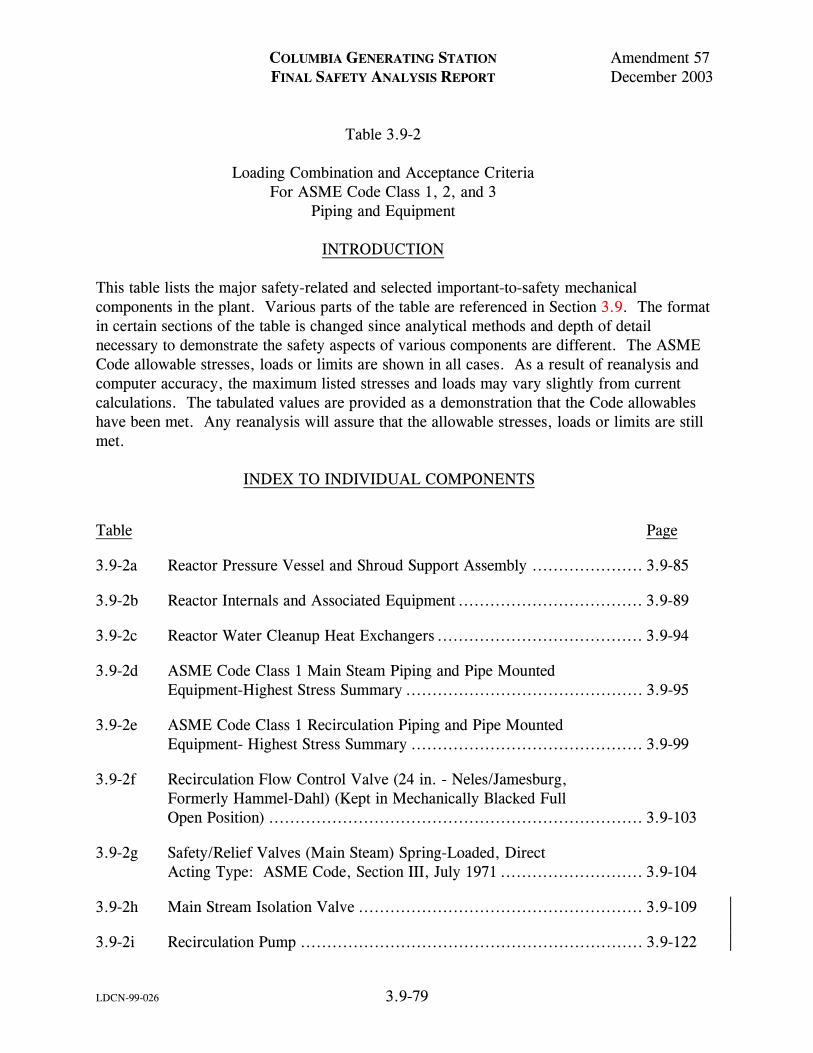
COLUMBIA GENERATING STATION Amendment 57 FINAL SAFETY ANALYSIS REPORT December 2003 Table 3.9-2 Loading Combination and Acceptance Criteria For ASME Code Class 1, 2, and 3 Piping and Equipment
LDCN-99-026 3.9-79
INTRODUCTION This table lists the major safety-related and selected important-to-safety mechanical components in the plant. Various parts of the table are referenced in Section 3.9. The format in certain sections of the table is changed since analytical methods and depth of detail necessary to demonstrate the safety aspects of various components are different. The ASME Code allowable stresses, loads or limits are shown in all cases. As a result of reanalysis and computer accuracy, the maximum listed stresses and loads may vary slightly from current calculations. The tabulated values are provided as a demonstration that the Code allowables have been met. Any reanalysis will assure that the allowable stresses, loads or limits are still met. INDEX TO INDIVIDUAL COMPONENTS
Table Page
3.9-2a Reactor Pressure Vessel and Shroud Support Assembly ..................... 3.9-85
3.9-2b Reactor Internals and Associated Equipment ................................... 3.9-89
3.9-2c Reactor Water Cleanup Heat Exchangers ....................................... 3.9-94
3.9-2d ASME Code Class 1 Main Steam Piping and Pipe Mounted Equipment-Highest Stress Summary ............................................. 3.9-95
3.9-2e ASME Code Class 1 Recirculation Piping and Pipe Mounted Equipment- Highest Stress Summary ............................................ 3.9-99
3.9-2f Recirculation Flow Control Valve (24 in. - Neles/Jamesburg, Formerly Hammel-Dahl) (Kept in Mechanically Blacked Full Open Position) ....................................................................... 3.9-103
3.9-2g Safety/Relief Valves (Main Steam) Spring-Loaded, Direct Acting Type: ASME Code, Section III, July 1971 ........................... 3.9-104
3.9-2h Main Stream Isolation Valve ...................................................... 3.9-109
3.9-2i Recirculation Pump ................................................................. 3.9-122

COLUMBIA GENERATING STATION Amendment 57 FINAL SAFETY ANALYSIS REPORT December 2003 Table 3.9-2 Loading Combination and Acceptance Criteria For ASME Code Class 1, 2, and 3 Piping and Equipment (Continued)
LDCN-99-026 3.9-80
3.9-2j Reactor Recirculation System Gate Valves, 24 in. Discharge Structural and Mechanical Loading Criteria .................................... 3.9-127
3.9-2k Not Used .............................................................................. 3.9-133
3.9-2L Standby Liquid Control Pump..................................................... 3.9-134
3.9-2m Standby Liquid Control Tank ..................................................... 3.9-138
3.9-2n Emergency Core Cooling System Pumps ....................................... 3.9-139
3.9-2o Residual Heat Removal Heat Exchanger ........................................ 3.9-142
3.9-2p Reactor Water Cleanup Pump..................................................... 3.9-146
3.9-2q Not Used .............................................................................. 3.9-147
3.9-2r Reactor Core Isolation Cooling Pump ........................................... 3.9-148
3.9-2s Reactor Refueling and Servicing Equipment ................................... 3.9-152
3.9-2t Not Used .............................................................................. 3.9-155
3.9-2u Control Rod Drive (Indicator Tube) ............................................. 3.9-156
3.9-2v Control Rod Drive Housing ....................................................... 3.9-157
3.9-2w Jet Pumps ............................................................................. 3.9-158
3.9-2x Not Used .............................................................................. 3.9-159
3.9-2y Low-Pressure Coolant Injection Coupling ...................................... 3.9-160
3.9-2z Not Used .............................................................................. 3.9-161
3.9-2aa Control Rod Guide Tube ........................................................... 3.9-162
3.9-2ab Incore Housing....................................................................... 3.9-163
3.9-2ac Reactor Vessel Support Equipment............................................... 3.9-164

COLUMBIA GENERATING STATION Amendment 56 FINAL SAFETY ANALYSIS REPORT December 2001 Table 3.9-2 Loading Combination and Acceptance Criteria For ASME Code Class 1, 2, and 3 Piping and Equipment (Continued)
LDCN-00-099 3.9-81
GE SCOPE OF SUPPLY
Load Combination SRSSa Design Basis Evaluation Basis
N + SRV(ALL) Upset Upset (B)
N + OBE Upset Upset (B)
N + [OBE2 + SRV2(ALL)]½ Emergency Upset (B)
N + [SSE2 + SRV2(ALL)]½ Faulted Faultedb (D)
N + [SBA2 + SRV2]½ Emergency Emergencyb (C)
N + [IBA2 + SRV2]½ Faulted Faultedb (D)
N + [SBA2 + SRV2(ADS)]½ Emergency Emergencyb (C)
N + [SBA2 + OBE2 + SRV2(ADS)]½ Faulted Faultedb (D)
N + [IBA2 + OBE2 + SRV2(ADS)]½ Faulted Faultedb (D)
N + [SBA2/IBA2 + SSE2 + SRV2(ADS)]½ Faulted Faultedb (D)
N + [cLOCA2 + SSE2]½ Faulted Faultedb (D)

COLUMBIA GENERATING STATION Amendment 56 FINAL SAFETY ANALYSIS REPORT December 2001 Table 3.9-2 Loading Combination and Acceptance Criteria For ASME Code Class 1, 2, and 3 Piping and Equipment (Continued)
LDCN-00-099 3.9-82
BALANCE-OF-PLANTd
Load Cases
SRSS Load Combinationse,f,g Design Assessment Acceptance
Criteria
1 P + DW Normal (A)
2 N + [OBE2 + SRV2ONE]½ Upset (B)
3 N + [OBE2 + SRV2TWO]½ Upset (B)
4 N + [OBE2 + SRV2ALL]½ Upset (B)
5 N + [OBE2 + SRV2ADS + SBA2]½ Emergencyb (C)
6 N + [OBE2 + SRV2TWO + SBA2]½ Emergencyb (C)
7 N + [SSE2 + SRV2ADS + SBA2/IBA2]½ Faultedb (D)
8 N + [SSE2 + SRV2TWO + SBA2/IBA2]½ Faultedb (D)
9 N + [SSE2 + SRV2ONE]½ Faultedb (D)
10 N + [SSE2 + SRV2TWO]½ Faultedb (D)
11 N + [SSE2 + SRV2ALL]½ Faultedb (D)
12 N + [SSE2 + DBA2]½ Faultedb (D)
LEGEND N Normal (and abnormal loads depending on acceptance criteria) include internal
pressure (P) and dead weight (DW). OBE Operating basis earthquake loads. SSE Safe shutdown earthquake loads.

COLUMBIA GENERATING STATION Amendment 53 FINAL SAFETY ANALYSIS REPORT November 1998 Table 3.9-2 Loading Combination and Acceptance Criteria For ASME Code Class 1, 2, and 3 Piping and Equipment (Continued)
3.9-83
SRV Safety/relief valve discharge induced loads from two adjacent valves (one valve actuated when adjacent valve is cycling).
SRVTWO Safety/relief valve discharge induced loads from two adjacent valves. (This
load is conservatively enveloped by the SRVONE case.) SRVALL The loads induced by actuation of all safety/relief valves which activate within
msec of each other (e.g., turbine trip operational transient). (This load is the largest of the axisymmetric and nearly symmetric all valve loading conditions.)
SRVADS The loads induced by actuation of safety/relief valves associated with the
automatic depressurization system which actuate within msec of each other during the postulated small or intermediate size pipe rupture. (This load is conservatively taken as the SVRALL case.)
SRVONE The loads induced by the actuation of one safety/relief valve. LOCAc The loss-of-coolant accident associated with the postulated pipe rupture of large
pipes (e.g., main steam, feedwater, recirculation piping). LOCA1 Pool swell drag/fallout loads on piping and components located between the
main vent discharge outlet and the suppression pool water upper surface. LOCA2 Pool swell impact loads on piping and components located above the
suppression pool water upper surface. LOCA3 Oscillating pressure induced loads on submerged piping and components during
condensation oscillations. LOCA4 Building motion induced loads from chugging. LOCA5 Building motion induced loads from main vent air clearing. LOCA6 Vertical and horizontal loads on main vent piping. LOCA7 Annulus pressurization loads. SBA The abnormal transients associated with a small break accident.

COLUMBIA GENERATING STATION Amendment 53 FINAL SAFETY ANALYSIS REPORT November 1998 Table 3.9-2 Loading Combination and Acceptance Criteria For ASME Code Class 1, 2, and 3 Piping and Equipment (Continued)
3.9-84
IBA The abnormal transients associated with an intermediate break accident. DBA The abnormal transients associated with a design basis break accident. a Square root of the sum of the squares (SRSS) combination of dynamic loads. b All ASME Code Class 1, 2, and 3 piping systems which are required to function for safe shutdown under the postulated events shall meet the requirements of NRC's memorandum, “Evaluation of Topical Report - Piping Functional Capability Criteria,” dated July 17, 1980. c The most limiting case of load combination among LOCA1 through LOCA7 d Equipment includes pumps, valves, supports, and vessels. e All dynamic loads are combined using the SRSS method and the results are added to the static loads. As an analysis option the simpler but more conservative absolute sum method was used in some load evaluations. f As required by the appropriate subsection, i.e., NB, NC, or ND of ASME Code Section III, Division 1; other loads, such as thermal transient, thermal gradients, and anchor points displacement portion of the OBE or SRV may require consideration in addition to those primary stress-producing loads listed. g SBA, IBA, and DBA include all event-induced loads, as applicable, such as chugging, pool swell, drag loads, annulus pressurization, etc.

C
OL
UM
BIA
GE
NE
RA
TIN
G S
TA
TIO
N A
mendm
ent 53
FIN
AL
SA
FE
TY
AN
AL
YSIS R
EP
OR
T
Novem
ber 1998
3.9-85
Table 3.9-2a
Reactor Pressure Vessel and Shroud Support Assembly (i) Vessel Support Skirt
ASME B&PV Code Section III Primary Stress Limit Criteria
Loading
Primary Stress Type
Allowable Stress (psi)
Maximum Calculated Stress (psi)
Material: SA 533 GR. B CL #1 A. Normal and upset condition: Pm ≤ Sm Sm = 26,700 @ 575°F PL + Pb ≤ 1.5 Sm
1.5 Sm = 40,050 @ 575°F
1. Normal loads 2. Upset pressure 3. Operating basis earthquake 4. Safety/relief valve
Primary membrane Primary membrane plus bending
26,700
40,050
19,911
28,369
B. Emergency condition: Pm ≤ Sy Sy = 42,300 @ 575°F PL + Pb ≤ 1.5 Sy 1.5 Sy = 63,450 @ 575°F
1. Normal loads 2. Upset pressure 3. Operating basis earthquake 4. Safety/relief valve
Primary membrane Primary membrane plus bending
42,300
63,450
39,245a
56,485a
C. Faulted condition: Pm ≤ Sy Sy = 42,300 @ 575°F PL + Pb ≤ 1.5 Sy 1.5 Sy = 63,450 @ 575°F
1. Normal loads 2. Faulted pressure 3. Chugging 4. Safety/relief valve (ADS) 5. Safe shutdown earthquake
Primary membrane Primary membrane plus bending
42,300b
63,450b
39,245
56,485
D. Maximum cumulative usage factor: 0.064 at skirt-base junction a Calculated stresses under faulted loading (greater than emergency loading). b Allowable stresses under emergency loading (less than faulted loading).
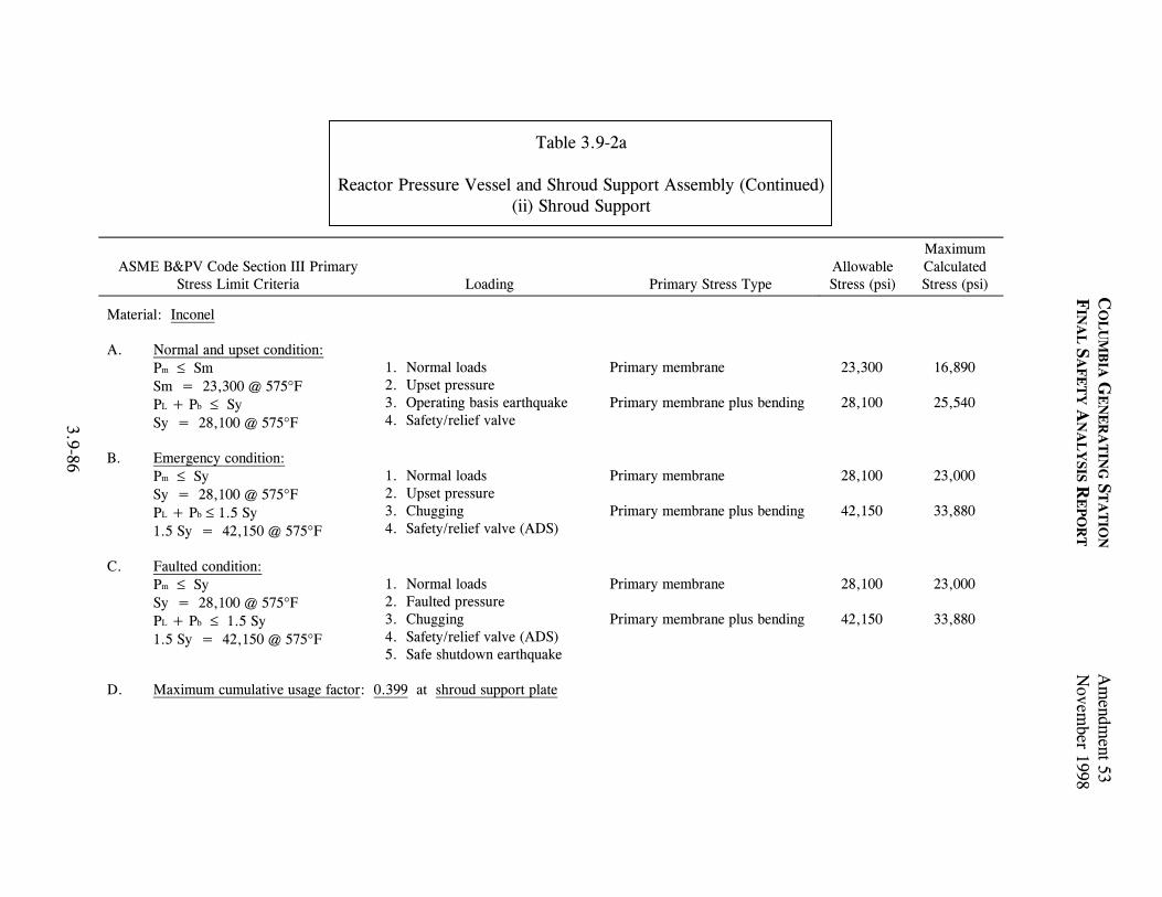
C
OL
UM
BIA
GE
NE
RA
TIN
G S
TA
TIO
N A
mendm
ent 53
FIN
AL
SA
FE
TY
AN
AL
YSIS R
EP
OR
T
Novem
ber 1998
3.9-86
Table 3.9-2a
Reactor Pressure Vessel and Shroud Support Assembly (Continued) (ii) Shroud Support
ASME B&PV Code Section III Primary Stress Limit Criteria
Loading
Primary Stress Type
Allowable Stress (psi)
Maximum Calculated Stress (psi)
Material: Inconel
A. Normal and upset condition: Pm ≤ Sm Sm = 23,300 @ 575°F PL + Pb ≤ Sy Sy = 28,100 @ 575°F
1. Normal loads 2. Upset pressure 3. Operating basis earthquake 4. Safety/relief valve
Primary membrane Primary membrane plus bending
23,300
28,100
16,890
25,540
B. Emergency condition: Pm ≤ Sy Sy = 28,100 @ 575°F PL + Pb ≤ 1.5 Sy 1.5 Sy = 42,150 @ 575°F
1. Normal loads 2. Upset pressure 3. Chugging 4. Safety/relief valve (ADS)
Primary membrane Primary membrane plus bending
28,100
42,150
23,000
33,880
C. Faulted condition: Pm ≤ Sy Sy = 28,100 @ 575°F PL + Pb ≤ 1.5 Sy 1.5 Sy = 42,150 @ 575°F
1. Normal loads 2. Faulted pressure 3. Chugging 4. Safety/relief valve (ADS) 5. Safe shutdown earthquake
Primary membrane Primary membrane plus bending
28,100
42,150
23,000
33,880
D. Maximum cumulative usage factor: 0.399 at shroud support plate

C
OL
UM
BIA
GE
NE
RA
TIN
G S
TA
TIO
N A
mendm
ent 61
FIN
AL
SA
FE
TY
AN
AL
YSIS R
EP
OR
TD
ecember 2011
LD
CN
-09-021 3.9-87
Table 3.9-2a
Reactor Pressure Vessel and Shroud Support Assembly (Continued) (iii) Reactor Pressure Vessel, Feedwater Nozzle
ASME B&PV Code Section III Primary Stress Limit Criteria
Loading
Primary Stress Type
Allowable Stress (psi)
Maximum Calculated Stress (psi)
Material: Inconel A. Normal and upset condition: Pm Sm Sm = 23,300 @ 575F PL + Pb Sy 1.5 Sm = 35,900 @ 575F
1. Normal loads 2. Upset pressure 3. Operating basis earthquake 4. Safety/relief valve
Primary membrane Primary membrane plus bending
23,300
35,000
13,848
15,120
B. Emergency condition: Pm 1.2 Sm 1.2 Sm = 27,960 @ 575F PL + Pb 1.5 Sy 1.5 Sy = 42,000 @ 575F
1. Normal loads 2. Upset pressure 3. Chugging 4. Safety/relief valve (ADS)
Primary membrane Primary membrane plus bending
27,960
42,000
17,719
20,060
C. Faulted condition: Pm 1.2 Sm 1.2 Sm = 27,960 @ 575F PL + Pb 1.5 Sy 1.5 Sy = 42,000 @ 575F
1. Normal loads 2. Faulted pressure 3. Jet reaction 4. Annulus pressurization 5. Safe shutdown earthquake
Primary membrane Primary membrane plus bending
27,960
42,000
17,719
33,610
D. Maximum cumulative usage factor: 0.696 at thermal sleeve to safe end

CO
LU
MB
IA G
EN
ER
AT
ING
ST
AT
ION
Am
endment 53
FIN
AL
SA
FE
TY
AN
AL
YSIS R
EP
OR
TN
ovember 1998
3.9-88
Table 3.9-2a
Reactor Pressure Vessel and Shroud Support Assembly (Continued) (iv) Control Rod Drive Penetration
ASME B&PV Code Section III Primary Stress Limit Criteria
Loading
Primary Stress Type
Allowable Stress (psi)
Maximum Calculated Stress (psi)
Material: Inconel SB157 (stub tube) A. Normal and upset condition: Pm ≤ Sm Sm = 16,650 @ 550°F PL + Pb ≤ Sy Sy = 24,100 @ 550°F
1. Normal loads 2. Upset pressure 3. Operating basis earthquake 4. Safety/relief valve
Primary membrane Primary membrane plus bending
16,650
24,100
2,099a
16,893a
B. Emergency condition: Pm ≤ 1.2 Sm 1.2 Sm = 19,980 @ 550°F PL + Pb ≤ 1.5 Sy 1.5 Sy = 35,150 @ 550°F
1. Normal loads 2. Upset pressure 3. Operating basis earthquake 4. Safety/relief valve
Primary membrane Primary membrane plus bending
19,980
36,150
2,099
16,893
C. Faulted condition: Pm ≤ 1.2 Sm 1.2 Sm = 19,980 @ 550°F PL + Pb ≤ 1.5 Sy 1.5 Sy = 35,150 @ 550°F
1. Normal loads 2. Faulted pressure 3. Jet reaction 4. Scram 5. Safe shutdown earthquake
Primary membrane Primary membrane plus bending
19,980b
36,150b
7,623
31,996
D: Maximum cumulative usage factor: 0.196 at CRD housing
a Calculated stresses under faulted loading (greater than normal and upset loading). b Allowable stresses under emergency loading (less than faulted loading).

C
OL
UM
BIA
GE
NE
RA
TIN
G S
TA
TIO
N A
mendm
ent 53
FIN
AL
SA
FE
TY
AN
AL
YSIS R
EP
OR
T
Novem
ber 1998
3.9-89
Table 3.9-2b
Reactor Internals and Associated Equipment (i) Top Guide - Highest Stressed Beam
ASME B&PV Code Section III Primary Stress Limit Criteria
Loading
Primary Stress Type
Allowable Stress (psi)
Maximum Calculated Stress (psi)
Material: 304 Stainless Steel
A. Normal and upset condition: Pm ≤ Sm Sm = 16,900 @ 550°F PL + Pb ≤ 1.5 Sm 1.5 Sm = 25,350 @ 550°F
1. Normal loads 2. Upset pressure 3. Operating basis earthquake 4. Safety/relief valve
Primary membrane Primary membrane plus bending
16,900
31,690a
819
28,548
B. Emergency condition: Pm ≤ 1.2 Sm 1.2 Sm = 20,280 @ 550°F PL + Pb ≤ 1.8 Sm 1.8 Sm = 30,420 @ 550°F
1. Normal loads 2. Upset pressure 3. Chugging 4. Safety/relief valve
Primary membrane Primary membrane plus bending
20,280
30,420
318
26,638
C. Faulted condition: Pm ≤ 2.4 Sm 2.4 Sm = 40,560 @ 550°F PL + Pb ≤ 3.0 Sm 3.0 Sm = 50,700 @ 550°F
1. Normal loads 2. Upset pressure 3. Safety/relief valve (ADS) 4. Safe shutdown earthquake
Primary membrane Primary membrane plus bending
40,560
50,700
900
35,919
D. Maximum cumulative usage factor: 0.1625 at longest beam slot
a Includes a factor of 1.25 as a result of certified yield strength test data.

C
OL
UM
BIA
GE
NE
RA
TIN
G S
TA
TIO
N A
mendm
ent 56
FIN
AL
SA
FE
TY
AN
AL
YSIS R
EP
OR
T
Decem
ber 2001
LD
CN
-00-099 3.9-90
Table 3.9-2b
Reactor Internals & Associated Equipment (Continued) (ii) Core Plate (Ligament In Top Plate)
ASME B&PV Code Section III Primary Stress Limit Criteria
Loading
Primary Stress Type
Allowable Stress (psi)
Maximum Calculated Stress (psi)
Material: 304 Stainless Steel
A. Normal and upset condition: Pm ≤ Sm Sm = 16,900 @ 550°F PL + Pb ≤ 1.5 Sm 1.5 Sm = 25,350 @ 550°F
1. Dead weight 2. Pressure 3. Operating basis earthquake 4. Safety/relief valve
Primary membrane Primary membrane plus bending
16,900
25,350
4,830
13,980
B. Emergency condition: Pm ≤ 1.2 Sm 1.2 Sm = 20,280 @ 550°F PL + Pb ≤ 1.8 Sm 1.8 Sm = 30,420 @ 550°F
1. Normal loads 2. Pressure 3. SBA (chugging) 4. Safety/relief valve
Primary membrane Primary membrane plus bending
20,280
30,420
1,630
12,080
C. Faulted condition: Pm ≤ 2.4 Sm 2.4 Sm = 40,560 @ 550°F PL + Pb ≤ 3.0 Sm 3.0 Sm = 50,700 @ 550°F
1. Dead weight 2. Pressure 3. Loss-of-coolant accident 4. Safety/relief valve 5. Safe shutdown earthquake
Primary membrane Primary membrane plus bending
40,560
50,700
5,330
20,600
D. Maximum cumulative usage factor: 0.005 at stiffener-rim junction

C
OL
UM
BIA
GE
NE
RA
TIN
G S
TA
TIO
N A
mendm
ent 53
FIN
AL
SA
FE
TY
AN
AL
YSIS R
EP
OR
T
Novem
ber 1998
3.9-91
Table 3.9-2b
Reactor Internals & Associated Equipment (Continued) (iii) Differential Pressure & Liquid Control Lines
ASME B&PV Code Section III Primary Stress Limit Criteria
Loading
Primary Stress Type
Allowable Stress (psi)
Maximum Calculated Stress (psi)
Material: 304 stainless steel
A. Normal and upset condition: Pm ≤ Sm Sm = 16,400 @ 550°F PL + Pb + Qm + Qb ≤ 3 Sm 3.0 Sm = 49,200 @ 550°F
1. Dead weight 2. Upset pressure 3. Safety/relief valve
Primary membrane plus bending and secondary membrane plus bending
49,200 42,725
B. Emergency condition: Pm ≤ 1.2 Sm 1.2 Sm = 19,680 @ 550°F PL + Pb ≤ 1.8 Sm 1.8 Sm = 29,520 @ 550°F
1. Normal loads 2. Upset pressure 3. Operating basis earthquake 4. Safety/relief valve
Primary membrane plus bending 29,520 17,015
C. Faulted condition: Pm ≤ 2.4 Sm 2.4 Sm = 39,360 @ 550°F PL + Pb ≤ 3.0 Sm 3.0 Sm = 49,200 @ 550°F
1. Normal loads 2. Faulted pressure 3. Jet reaction 4. Annulus pressurization 5. Safe shutdown earthquake
Primary membrane plus bending 49,200 21,664

C
OL
UM
BIA
GE
NE
RA
TIN
G S
TA
TIO
N A
mendm
ent 53
FIN
AL
SA
FE
TY
AN
AL
YSIS R
EP
OR
T
Novem
ber 1998
3.9-92
Table 3.9-2b
Reactor Internals & Associated Equipment (Continued) (iv) Vessel Head Spray Nozzle
ASME B&PV Code Section III Primary
Stress Limit Criteria
Loading
Limiting Stress Type Allowable Stress
(psi) Calculated Stress
(psi)
A. Normal and upset condition: Sm @ 575°F = 17.7 k/psi Su @ 575°F = 60.0 Ksi Slimit = 3.0 Sm
1. Normal loads 2. Normal pressure 3. Operating basis earthquake
Primary membrane plus bending and secondary membrane plus bending
53,100 31,357
B. Emergency condition: Sm @ 575°F = 17.7 k/psi Su @ 575°F = 60.0 Ksi Slimit = 1.5 (0.7 Su)
1. Normal loads 2. Upset pressure 3. Operating basis earthquake 4. Safety/relief valve
Primary membrane plus bending
31,900 17,713
C: Faulted condition:a Sm @ 575°F = 17.7 k/psi Su @ 575°F = 60.0 Ksi Slimit = 1.5 (0.7 Su)
1. Normal loads 2. Faulted pressure 3. Chugging 4. Safety/relief valve (ADS) 5. Safe shutdown earthquake OR 1. Normal loads 2. Faulted pressure 3. Jet reaction 4. Annulus pressurization 5. Safe shutdown earthquake
Primary membrane plus bending
63,000 27,840
a Calculated faulted stress value is the maximum stress resulting from either of the two faulted loading conditions.

CO
LU
MB
IA G
EN
ER
AT
ING
ST
AT
ION
Am
endment59
FIN
AL
SA
FE
TY
AN
AL
YSIS R
EP
OR
TD
ecember 2007
LD
CN
-07-011 3.9-93
Table 3.9-2b
Reactor Internals & Associated Equipment (Continued) (v) GE Fuel Assembly (Including Channel)
Acceptance Criteria
Loading
Primary Load Type Calculated Peak
Acceleration Evaluation Basis
Acceleration
Acceleration envelope Horizontal direction: 1. Peak pressure 2. Safe shutdown earthquake 3. Annulus pressurization
Horizontal acceleration profile 1.5g (1)
Vertical direction: Vertical accelerations 5.1g (4) (1) 1. Peak pressure
2. Safe shutdown earthquake 3. Safety/relief valve 4. Chugging
Notes: 1. Evaluation basis accelerations and evaluations are contained in Reference 3.9-7. 2. The calculated maximum fuel assembly gap opening for the most limiting load combination is 0.25(4) in. 3. The fatigue analysis indicates that the fuel assembly has adequate fatigue capability to capability to withstand the loadings resulting from
multiple SRV actuations and the OBE+SRV event. 4. These values are determined using the methodology contained in Reference 3.9-7.

CO
LU
MB
IA G
EN
ER
AT
ING
ST
AT
ION
Am
endment53
FIN
AL
SA
FE
TY
AN
AL
YSIS R
EP
OR
TN
ovember 1998
3.9-94
Table 3.9-2c
Reactor Water Cleanup Heat Exchangers
Part Required Thickness (in.) Allow Stress (psi) Actual Thickness (in.)
Regenerative CU HX
Shell 0.858 15,000 1.156
Shell head 0.704 17,500 1.0
Channel shell 0.917 15,900 1.0a
Tubesheet 2.87 15,900 2.875a
Tubes 0.084 11,900 0.095
Piping 0.240 15,000 0.337
Channel cover 3.53 17,500 3.75a Non-regenerative CU HX
Shell 0.168 15,000 0.375
Shell head 0.144 17,500 0.375
Channel shell 0.917 15,900 0.937a
Channel cover 3.53 17,500 3.75a
Tubesheet 2.87 15,900 2.875a
Tubes 0.056 11,900 0.065a
Channel cover 2.40 15,000 0.337
Shell Piping 0.073 15,000 0.322

C
OL
UM
BIA
GE
NE
RA
TIN
G S
TA
TIO
N A
mendm
ent 53
FIN
AL
SA
FE
TY
AN
AL
YSIS R
EP
OR
T
Novem
ber 1998
3.9-95
Table 3.9-2d
ASME Code Class 1 Main Steam Piping and Pipe Mounted Equipment - Highest Stress Summary
Acceptance Criteria
Limiting
Stress Type
Calculated Stress or
Usage Factor
Allowable
Limits
Ratio Actual/
Allowable
Loading
Identification of Locations of
Highest Stress
ASME B&PV Code Section III, NB-3650
Design Condition: Eq. 9 ≤ 1.5 Sm
Primary
22,881 psi
26,550 psi
0.86
1. Pressure 2. Weight 3. Operating basis earthquake
At MSIV (steam line C)
Service levels A & B (normal and upset) condition: Eq. 12 ≤ 3.0 Sm
Secondary
45,951 psi
53,100 psi
0.87
1. Pressure 2. Weight 3. Operating transient 4. Operating basis earthquake
At sweepolet (steam line B)
Service levels A & B (normal and upset) condition: Eq. 13 ≤ 3.0 Sm
Primary plus secondary (except thermal expansion)
52,789 psi
53,100 psi
0.99
1. Pressure 2. Weight 3. Operating basis earthquake 4. Operating transient
At sweepolet (steam line D)
Service levels A & B (normal and upset) condition: Cumulative usage factor:
N/A
0.72
1.0
1. Pressure 2. Weight 3. Operating basis earthquake 4. Operating transient
At sweepolet (steam line B)

C
OL
UM
BIA
GE
NE
RA
TIN
G S
TA
TIO
N A
mendm
ent 53
FIN
AL
SA
FE
TY
AN
AL
YSIS R
EP
OR
T
Novem
ber 1998
3.9-96
Table 3.9-2d
ASME Code Class 1 Main Steam Piping and Pipe Mounted Equipment - Highest Stress Summary (Continued)
Acceptance Criteria
Limiting
Stress Type
Calculated Stress (psi)
Allowable Stress Limits
(psi)
Ratio Actual/
Allowable
Loading
Identification of Locations of
Highest Stress
Service level B (upset) condition: Eq. 9 ≤ 1.8 Sm & 1.5 Sy
Primary
5,741
31,860
0.81
1. Pressure 2. Weight 3. Operating basis earthquake4. Operating transient
At sweepolet (steam line D)
Service level C (emergency) condition: Eq. 9 < 2.25 Sm & 1.8 Sy
Primary
23,429
39,825
0.60
1. Pressure 2. Weight 3. Operating transient 4. Small break accident
At MSIV (steam line C)
Service level D (faulted) condition: Eq. 9 < 3.0 Sm
Primary
32,673
53,100
0.62
1. Pressure 2. Weight 3. Safe shutdown earthquake 4. Loss-of-coolant accident
At sweepolet (steam line B)

C
OL
UM
BIA
GE
NE
RA
TIN
G S
TA
TIO
N A
mendm
ent 53
FIN
AL
SA
FE
TY
AN
AL
YSIS R
EP
OR
T
Novem
ber 1998
3.9-97
Table 3.9-2d
ASME Code Class 1 Main Steam Piping and Pipe Mounted Equipment - Highest Stress Summary (Continued)
Component/Load Type
Highest Calculated Load (lb)
Allowable Load
(lb)
Ratio Calculated/ Allowable
Loading
Identification of Equipment with Highest Loads
Snubber/level B 35,352 120,000 0.30 1. Pressure 2. Weight 3. Operating basis earthquake 4. Operating transients
MS-SC-1 Line C
Snubber/level C 49,559 160,000 0.31 1. Pressure 2. Weight 3. Small break accident 4. Associated operating transients
MS-SC-2 Line C
Snubber/level D 51,296 190,000 0.27 1. Pressure 2. Weight 3. Intermediate break accident4. Safe shutdown earthquake 5. Associated operating transients
MS-SC-2 Line C

C
OL
UM
BIA
GE
NE
RA
TIN
G S
TA
TIO
N A
mendm
ent 53
FIN
AL
SA
FE
TY
AN
AL
YSIS R
EP
OR
T
Novem
ber 1998
3.9-98
Table 3.9-2d
ASME Code Class 1 Main Steam Piping and Pipe Mounted Equipment - Highest Stress Summary (Continued)
Component/Load Type
Highest Calculated Load
(lb)
Allowable Load
(lb)
Ratio Calculated/ Allowable
Loading
Identification of Equipment with Highest Loads
Safety/relief valves (SRV) Horizontal acceleration 3.02g 5.2g 0.58 1. Pressure
2. Weight 3. Safe shutdown earthquake4. Loss-of-coolant accident
SRV 4B line B
Vertical acceleration 1.55g 4.4g 0.35 1. Pressure 2. Weight 3. Safe shutdown earthquake4. Loss-of-coolant accident
SRC 5C line C
Main steam isolation valve (MSIV) Level B - moment 1960 in.-Kips 28,750 in.-Kips 0.07 1. Pressure
2. Weight 3. OBA 4. Operating transients
Nozzle line D
Level C - moment 2287 in.-Kips 28,750 in.-Kips 0.08 1. Pressure 2. Weight 3. Operating transients 4. Small break accident
Nozzle line D
Level D - moment 2395 in.-Kips 28,750 in.-Kips 0.08 1. Pressure 2. Weight 3. Operating transients 4. Safe shutdown earthquake5. Loss-of-coolant accident
Nozzle line D

C
OL
UM
BIA
GE
NE
RA
TIN
G S
TA
TIO
N A
mendm
ent 53
FIN
AL
SA
FE
TY
AN
AL
YSIS R
EP
OR
T
Novem
ber 1998
3.9-99
Table 3.9-2e
ASME Code Class 1 Recirculation Piping and Pipe Mounted Equipment - Highest Stress Summary
Acceptance Criteria
Limiting Stress
Type
Calculated Stress or Usage
Factor
Allowable
Limits
Ratio Actual/
Allowable
Loading
Identification of Locations of Highest
Stress Points
ASME B&PV Code Section III, NB-3650
Design condition: Eq. 9≤ 1.5 Sm
Primary
15,333 psi
25,013 psi
0.61
1. Pressure 2. Weight 3. OBE
RHR supply Loop A Node 327
Service levels A & B (normal and upset) condition: Eq. 12 ≤ 3.0 Sm
Secondary
33,468 psi
50,025 psi
0.67
1. Pressure 2. Weight 3. OBE 4. Operating transients
Header sweepolet Loop A Node 082
Service levels A & B (normal and upset) condition: Eq. 13 ≤ 3.0 Sm
Primary plus secondary (except thermal expansion)
36,760 psi
50,025 psi
0.74
1. Pressure 2. Weight 3. OBE 4. Operating transients
RHR supply Loop A Node 330
Service levels A & B (normal and upset) condition: Cumulative usage factor
N/A
0.85
1.0
0.85
Header sweepolet Loop A Node 082

C
OL
UM
BIA
GE
NE
RA
TIN
G S
TA
TIO
N A
mendm
ent 53
FIN
AL
SA
FE
TY
AN
AL
YSIS R
EP
OR
T
Novem
ber 1998
3.9-100
Table 3.9-2e
ASME Code Class 1 Recirculation Piping and Pipe Mounted Equipment - Highest Stress Summary (Continued)
Acceptance Criteria
Limiting Stress Type
Calculated Stress or
Usage Factor
Allowable
Limits
Ratio Actual/
Allowable
Loading
Identification of Locations of Highest
Stress Points
Service level B (upset) condition: Eq. 9 ≤ 1.8 Sm & 1.5 Sy
Primary
25,217 psi
28,200
0.89
1. Pressure 2. Weight 3. Operating basis earthquake 4. Operating transients
RHR TEE Loop A Node 322
Service level C (emergency) condition: Eq. 9 ≤ 2.25 Sm & 1.8 Sy
Primary
22,172 psi
33,840
0.66
1. Pressure 2. Weight 3. Operating transients 4. Small break accident
RHR TEE Loop A Node 322
Service level D (faulted) condition: Eq. 9 ≤ 3.0 Sm & 2.0 Sy
Primary
27,965 psi
37,600
0.74
1. Pressure 2. Weight 3. Loss-of-coolant accident 4. Safe shutdown earthquake
RHR TEE Loop A Node 322

C
OL
UM
BIA
GE
NE
RA
TIN
G S
TA
TIO
N A
mendm
ent 56
FIN
AL
SA
FE
TY
AN
AL
YSIS R
EP
OR
T
Decem
ber 2001
LD
CN
-00-099 3.9-101
Table 3.9-2e
ASME Code Class 1 Recirculation Piping and Pipe Mounted Equipment - Highest Stress Summary (Continued)
Component/ Load Type
Highest
Calculated Load
Allowable
Load
Ratio Calculated Allowable
Identification of Equipment
with Highest Loads
Suction gate valve
- Moment (in.-lb) 773,261 3,146,380 0.25 Body C.G. Loop A
Discharge gate valve
- Moment (in.-lb) 326,189 1,000,000 0.33 Body C.G. Loop B
Recirculation pump
- Horizontal acceleration
1.72g 4.5g 0.38 Motor C.G. Loop B
- Vertical acceleration
1.8g 3.5g 0.51 Motor C.G. Loop B
Flow control valve (mechanically blocked open)
- Horizontal acceleration
3.0g 9.0g 0.33 Operator Loop A
- Vertical acceleration
2.3g 6.0g 0.38 Operator Loop A

C
OL
UM
BIA
GE
NE
RA
TIN
G S
TA
TIO
N A
mendm
ent 53
FIN
AL
SA
FE
TY
AN
AL
YSIS R
EP
OR
T
Novem
ber 1998
3.9-102
Table 3.9-2e
ASME Code Class 1 Recirculation Piping and Pipe Mounted Equipment - Highest Stress Summary (Continued)
Component/Load Type
Highest Calculated
Load (lb)
Allowable Load (lb)
Ratio Calculated Allowable
Loading
Identification of Equipment with Highest Loads
Snubber/level B 53,009 120,000 0.44 1. Pressure 2. Weight 3. Operating basis earthquake4. Operating transients
SB6 Loop B
Snubber/level C 30,490 159,600 0.19 1. Pressure 2. Weight 3. Small break accident 4. Associated operating transients
SA6 Loop A
Snubber/level D 57,001 180,000 0.32 1. Pressure 2. Weight 3. Loss-of-coolant accident 4. Safe shutdown earthquake 5. Associated operating transients
SB6 Loop B

C
OL
UM
BIA
GE
NE
RA
TIN
G S
TA
TIO
N A
mendm
ent 56
FIN
AL
SA
FE
TY
AN
AL
YSIS R
EP
OR
T
Decem
ber 2001
LD
CN
-00-099 3.9-103
Table 3.9-2f
Recirculation Flow Control Valve (24 in. - Neles/Jamesburg, Formerly Hammel-Dahl) (Kept in Mechanically Blocked Full Open Position)
Criteria
Method of Analysis
Allowable ValueAnalytically Determined
Value
1. Body primary stress Per Subarticle NB-3500 of the ASME Code, Section III
19,600 psi 17,286 psi
2. Body to top housing flange joint at maximum stress point
Per Subarticle NB-3500 of the ASME Code, Section III
28,650 psi 24,910 psia
3. Housing to bonnet flange joint at maximum stress point
Per Subarticle, NB-3500 of the ASME Code, Section III
28,650 psi 2,934 psia
4. Body to bottom cover joint at maximum stress point
Per Subarticle NB-3500 of the ASME Code, Section III
N/A N/A
5. Top housing to top cover joint at maximum stress point
Per Subarticle NB-3500 of the ASME Code, Section III
28,650 psi 22,230 psia
6. Body minimum wall Per Subarticle NB-3541 of the ASME Code, Section III
2.417 in. 2.437 in.
a Flow control valve accelerations on Table 3.9-2e have been reduced, therefore these stresses will be reduced as well.

C
OL
UM
BIA
GE
NE
RA
TIN
G S
TA
TIO
N A
mendm
ent 56
FIN
AL
SA
FE
TY
AN
AL
YSIS R
EP
OR
T
Decem
ber 2001
LD
CN
-00-099 3.9-104
Table 3.9-2g
Safety/Relief Valves (Main Steam) Spring-Loaded, Direct Acting Type ASME Code, Section III, July 1971
Topic Method of Analysis Crosby 6-R-10 Analysis Allowable Value Calculated
Body inlet and outlet flange stresses
SHfMo
Lg B
Pb4go
1.5 Sm21
= + < (Codes) P(Crosby)P4g
BP
BLg
fMob
1
b
12
++ 1.5 Sm = 27,300 psi (inlet)
Inlet: SH = 1.2 Sm = 0.8 (allowable)
S
te Mo
Lt BSmR = + <( / )
.2
4 3 115 (Codes)g,g (Crosby)g
J;Lt1)Mo3 / (4te
1o12 =+
and = 29,000 psi (outlet)
SR = 0.3 Sm = 0.2 (allowable)
S
YMo
t bZS SmT R= − <
2 1 5.
YMo
t b ZS J Crosby B CodesR2 − =( ) ( )
ST = 1.4 Sm = 0.92 (allowable)
where: SH = Longitudinal “hub” wall stress, psi
Material: A-105, Grade II Inlet: Sm @ 575°F = 18,200 psi Outlet: Sm @ 500°F = 19,400 psi
Outlet SH = 0.82 Sm = 0.55 (allowable) SR = 0.99 Sm = 0.66 (allowable) ST = 0.27 Sm = 0.18 (allowable)
SR = Radial “flange” (body, base, inlet) ST = Tangential “flange” stress, psi
Inlet and outlet stud area requirement
Total cross-sectional area shall exceed the greater of: Am1= Wm
Sb1
Am Wm
Sbor1
1= , AM
Wm
Sa22=
Am Wm
Sa22=
Inlet: Am1 (Am2) Outlet: Am1 (Am2)
Inlet: Am (actual)/(required minimum) = 1.61 Outlet: Am (actual)/(required minimum) = 2.0
where: Am1 = total required bolt (stud) area for operation condition. Am2 = total required bolt (stud) area for gasket seating.

C
OL
UM
BIA
GE
NE
RA
TIN
G S
TA
TIO
N A
mendm
ent 56
FIN
AL
SA
FE
TY
AN
AL
YSIS R
EP
OR
T
Decem
ber 2001
3.9-105
Table 3.9-2g
Safety/Relief Valves (Main Steam) Spring-Loaded, Direct Acting Type (Continued) ASME Code, Section III, July 1971
Topic Method of Analysis Crosby 6-R-10 Analysis Allowable Value Calculated
Nozzle wall thickness
1. Valve Wall thickness Criterion:tminimum < tA
Thin section near valve seat: t m t a1 1 1 1−
<−
tm1 1− =
tm2 2− =
t a tm1 112
1 1−=
−. ( )
t a tm2 213
2 2−=
−. ( )
where: tminimum = minimum calculated thickness requirement, including corrosion allowance.
Section at about middle of nozzle: tm t a2 2 2 2−
<−
0.468 in. Actual thickness greater than tm at the section under consideration.
tA = Actual nozzle wall thickness. (NOTE: This tminimum is tm per notation of the codes.)
2. Cyclic Rating:
Thermal
ItNriNi
=∑
ItNriNi
i=∑ =( , ,& )1 2 3 It (max.)< 1 It = 0.032 (= 0.032 (It max.))
Fatigue Na > 2000 cycles, as based on Sa, where Sa is defined as the larger of
Na ≥ 2000 cycles, as based on SP, where SP (Crosby) = Sa (Codes)
Na ≥ 2000 cycles Na (based on SP = SP1) > 106
cycles:
SP P
Peb QT QT1 2 32 2
1301
= + + +( / )Q . (Uses same notation as codes) satisfies criterion
SP QP
K P eb QT2 0 42
22
= + + +. ( )

C
OL
UM
BIA
GE
NE
RA
TIN
G S
TA
TIO
N A
mendm
ent 56
FIN
AL
SA
FE
TY
AN
AL
YSIS R
EP
OR
T
Decem
ber 2001
3.9-106
Table 3.9-2g
Safety/Relief Valves (Main Steam) Spring-Loaded, Direct Acting Type (Continued) ASME Code, Section III, July 1971
Topic Method of Analysis Crosby 6-R-10 Analysis Allowable Value Calculated
Nozzle wall thickness (continued)
Fatigue (continued)
where: SP1 = Fatigue stress intensity at
inside surface of crotch, psi. SP1 = Fatigue stress intensity at
outside surface of crotch, psi.
Bonnet flange strength
Sm1.5ZSBt
YMoS
Sm1.5B2Lt
1)Mo(4te/3RS
Sm1.5o4g
PB
B12
Lg
fMoHS
R2T <−=
<+=
<+=
−
+
+
R2
2
ZSBt
YMoBLT
1)Mo(4te/3
14gBBP
B12
Lg
fMo
1.5 Sm (for maximum SH’ SR’ ST) PB (Crosby)=PC(Codes)=29,100 psi g1(Crosby)=g0g1,(Codes)
SH = 1.47 Sm = 0.98 (allowable) SR = 0.45 Sm = 0.3 (allowable)
ST= 0.46 Sm
= 0.31 (allowable)
where: SH = Longitudinal “hub”
wall stress, psi. Material: A-105, Grade II Sm at 500 °F = 19,400 psi
SR = Radial “flange” stress, psi. ST = Tangential “flange”
stress, psi.

C
OL
UM
BIA
GE
NE
RA
TIN
G S
TA
TIO
N A
mendm
ent 57
FIN
AL
SA
FE
TY
AN
AL
YSIS R
EP
OR
T
Decem
ber 2003
LD
CN
-99-026 3.9-107
Table 3.9-2g
Safety/Relief Valves (Main Steam) Spring-Loaded, Direct Acting Type (Continued) ASME Code, Section III, July 1971
Topic Method of Analysis Crosby 6-R-10 Analysis Allowable Value Calculated
Bonnet stud area requirements
Total cross-sectional area shall exceed the greater of: Am
WM
Sb1
1= Am1 (>Am2) Am (actual) = 1.4
(required minimum)
Am
Wm
Sb or1
1= , Am Wm
Sa22=
Am
Wm
Sa22=
where Am1 = Total required bolt (stud) area for
operating condition. Am2 = Total required bolt (stud) area for
gasket seating.
Disc insert Part No. N97499 (Valve Dwg. DS-A-63790-3)
Method of Analysis: Algor SUPERSAP (finite element) Computer Program, SSAP0.
Due to the complex geometrical shape of the 6R10 HB-BP-DF disc insert, a finite element computer model of the disc was constructed as follows: A half cross section two dimensional axisymmetric model was selected to represent the disc insert, since it is axisymmetric in shape, loading, and restraint about the vertical centerline.
The most severe loading condition, “the valve is unpressurized with the spring compressed to establish valve set load” was compared with the lowest allowable stress intensity (at design temperature 575°F).

C
OL
UM
BIA
GE
NE
RA
TIN
G S
TA
TIO
N A
mendm
ent 57
FIN
AL
SA
FE
TY
AN
AL
YSIS R
EP
OR
T
Decem
ber 2003
LD
CN
-99-026 3.9-108
Table 3.9-2g
Safety/Relief Valves (Main Steam) Spring-Loaded, Direct Acting Type (Continued) ASME Code, Section III, July 1971
Topic Method of Analysis Crosby 6-R-10 Analysis Allowable Value Calculated
Disc insert (continued)
Part No. N97499 (Valve Dwg. DS-A-63790-3)
Where: PSET= Set Pressure, 1250 psig FSET= Set Load, 24,950 lb a= ½ disc insert undercut diameter, 2.782 in. t= Design minimum thickness, 0.616 in. Si= Maximum bending stress intensities, psi
w = System pressure, 0 psig Ds = Disc inside diameter, 5.041 in. b= Hub radius 0.591 in. m= Reciprocal of Poisson’s ratio, 3.333
Material: SA-637 TP 718 (SA/SB-637 Gr.718) Sm= 45,225 psi (575°F), Allowable bending stress intensity: 1.5 Sm= 67,838 psi (@ 575°F)
SSAP0 { Algor SUPERSAP (finite element) Computer Program }
(At lower surface)
(At upper surface) 1.5 Sm = 67,838 psi 1.5 Sm = 67,838 psi
Si= 23,100 psi Si= 19,600 psi
Spring washer stress requirements Ss
F TAs
= (Same notation) SS<0.6 Sm SS = 0.15 Sm
= 0.25 (allowable)
where: Material: A-105, Grade II
FT = Total spring load at full lift Sm (at 400°F) = 26,000 psi As = Shear area, (in.)2

C
OL
UM
BIA
GE
NE
RA
TIN
G S
TA
TIO
N A
mendm
ent 57
FIN
AL
SA
FE
TY
AN
AL
YSIS R
EP
OR
T
Decem
ber 2003
3.9-109
Table 3.9-2h
Main Steam Isolation Valve
Criteria
Method of Analysis
Allowable Stress or Minimum Thickness
Calculated Stress or Actual Thickness
Design of pressure retaining parts
All references are made to ASME Boiler & Pressure Vessel Code, Section III, Nuclear Power Plant Components, 1971 Edition as Addended through Winter 1971. Reference the same code for explanation of the symbols used.
Body minimum wall thickness
Reference paragraph NB-3543, Nonstandard Pressure-Rated Valve, Table NB-1542-1.
For design condition of 1250 psig and 575°F. The primary service rating = 495 based on a core diameter of 23.9 in.
tm = 1.58 in. (Including a corrosion allowance of 0.12 in.).
1.58 in.
2.12 in.
Body shape rule Reference paragraph NB-3544, Body Shape Rules
Radius of crotch Reference paragraph NB-3544.1(a), Radius of Crotch criterion r2 ≥ 0.3 tm as r2 = 1.00 in., tm = 1.58 + 1.00
0.3 x 1.58 = 0.47 criterion satisfied
Corner radii on internal surfaces
Reference paragraph NB-3544.1(b), Corner Radii on Internal Surfaces criterion r4 < r2 as r4 = 0.69 in., r2 = 1.00 in. + 0.69 < 1.00
criterion satisfied
Out of roundness Reference paragraph NB-3544.5, Out of Roundness, Figure NB-3545.1-2
bt b
ab a
t b
SmPs
+ − − + ≤34
3b2 2 2
2 1 15.
a = 10.20 in., b = 15.75 in., c = 4.13 in. Sm = 19,400 psi 18.83 ≤21.56 Criterion satisfied

C
OL
UM
BIA
GE
NE
RA
TIN
G S
TA
TIO
N A
mendm
ent 57
FIN
AL
SA
FE
TY
AN
AL
YSIS R
EP
OR
T
Decem
ber 2003
3.9-110
Table 3.9-2h
Main Steam Isolation Valve (Continued)
Criteria
Method of Analysis
Allowable Stress or Minimum Thickness
Calculated Stress or Actual Thickness
Longitudinal curvature Reference paragraph NB-3544.6 Longitudinal Curvature
Criterion
Long Lat dmas rLong in.γ γ1 1 4
3 35 31
. . . . ,+ − =
rLat. = 15.75 in., dm = 23.90 in., + 0.09 ≤ 0.06
criterion satisfied
Flat wall limitation Reference paragraph NB-3544.7, Flat Wall Limitation
dt
dmtm
dmtmdt
in.in.in.in.
−====
32
23 9015835 764 06
....
Minimum wall at weld end
Reference paragraph NB-3544.8, Minimum Wall at Weld End
Actual thickness at 1 x tm (i.e., 1.58 in. measured along the run direction) is 3.80 in.
1.58 in. 3.80 in.
Primary crotch Stress due to internal pressure
Reference paragraph NB-3545.1
criterion P PS Smm AA
f
m= +( . )0 5
where Af = 591.8 in.2, Am = 128.4 in.2, PS = 1,350 psig, 19,400 psi 6,897 psi
Pm = 6,897 psi, Sm = 19,400 psi, since Sm Pm
criterion satisfied
Valve body secondary stress
Reference paragraph NB-3545.2

C
OL
UM
BIA
GE
NE
RA
TIN
G S
TA
TIO
N A
mendm
ent 57
FIN
AL
SA
FE
TY
AN
AL
YSIS R
EP
OR
T
Decem
ber 2003
3.9-111
Table 3.9-2h
Main Steam Isolation Valve (Continued)
Criteria
Method of Analysis
Allowable Stress (psi)
Calculated Stress (psi)
Primary plus secondary stress due to internal pressure
Reference paragraphs NB-3545.2(a)(1), NB-3545.2(a)(2)
Q Crit e
P CaP P S= +( . )0 5
where CP = 3, ri = 11.80 in., PS = 1350 psi. te =
3.80, QP = 14,601 psi for wye-type valve Ca = 1.33 + QP = 19,420
Secondary stress due to pipe reaction
Reference paragraph NB-3545.2(b), Figures NB-3545.2-3. NB-3545.2-5, and NB-3545.2-6
Direct or axial load effect Ped
FdS
GdwhereS Fd in. Gd in.= = = =41 000 34 5 2 314 8 2, . . .
29,100 4,493
→ =P psied 4493
Bending load effect P C
F S
Gwhere S F in.eb b
b
bb= = =41 000 380 3, ,
i d in. ri te in.r. . . , . , . .= = =23 65 1180 3 80 13 70
as
t
r Ce
b= > + =0 257 019 1. .
Gb
Ir t
where I in. r in.i e
i=+
= =30 453 11834, , . ,
te = 3.80 Gb 1948 in. 3
→ Peb = 7998 psi 29,100 7,998

C
OL
UM
BIA
GE
NE
RA
TIN
G S
TA
TIO
N A
mendm
ent 57
FIN
AL
SA
FE
TY
AN
AL
YSIS R
EP
OR
T
Decem
ber 2003
3.9-112
Table 3.9-2h
Main Steam Isolation Valve (Continued)
Criteria Method of Analysis Allowable Stress (psi) Calculated Stress (psi)
Torsion load effect Reference paragraphs 3545.29(b)(1). 3545.2(b)(6)(c)
Pet
FbS
Gtwhere Fb in. S psi= = =2 380 3 41 000, ,
Gt Ct tA t in. A in. Ct Gt in.= = = = =3 43 596 2 1 78 3639 3. , , . , . 29,100 8,563
Pet = 8563 psi
Thermal secondary stress at crotch region
Reference paragraph NB-3545.2(c), Figures NB-3545.2(c)-2, NB-3545.2(c)-3, and NB-3545.2(c)-4
Q Q QT T T= +1 2
where Te in. QT1 5 201
3200= =. ,
CT C C T whereC C and T F2 6 2 2 0 48 6 210 2 162= = = =∆ ∆. . o
QT psi QT psi2
161 3361= =,
criterion SN QP Ped QT Sm= + + ≤22
3
where QP Ped QT= = =19 420 44932
161,
as 24,235 ≤ 58,200 criterion satisfied 58,200 24,235
Normal duty valve fatigue requirements
Reference paragraphs 3545.3, NB-3545.3(a), NB-3545.3a, and Figure 1-9-1 criterion Na ≥ 2,000 cycles

C
OL
UM
BIA
GE
NE
RA
TIN
G S
TA
TIO
N A
mendm
ent 57
FIN
AL
SA
FE
TY
AN
AL
YSIS R
EP
OR
T
Decem
ber 2003
3.9-113
Table 3.9-2h
Main Steam Isolation Valve (Continued)
Criteria
Method of Analysis
Allowable Stress (psi)
Calculated Stress (psi)
Normal duty valve fatigue requirements (continued)
SP Q PP eb
QT QT SP Q P K
Peb QT123 2 3
131 2
0 42
23
= + + + = + +' . . ( )
where Q P Peb Kr QT' , ,= = =19 420 7998 21
3200
QT psi SP SP Sa equal to the l er of SP and3
1751
21 2672
16 116 1
= + = =, , arg
S SP a2 21 267→ = , + Na = 75,000 ≥ 2,000 criterion satisfied
Cyclic loading requirements at valve crotch
Reference paragraph NB-3550 For the largest temperature change range criterion Q’ + Ped + C6C2C4 ∆Tf max ≤ 3 Sm
where Q’P = 19,420 psi, Ped = 4493 C6 = 210 at ∆Tf
max of 342°F, C2 = 0.48, C4 = 0.15 Sm = 19,400
→ 29,084 ≤ 58,200 criterion satisfied 58,200 29,084
Thermal Transients Not Excluded by Code Criterion
N
Nri
i∑ < 1
Calculate the fatigue usage factor (It) as follows:
Sn Max = Q’ P + Peb + C6C3C4∆Tf max + Sn max = 33,343 psi
Since Sn max < 3 Sm (= 58,200) the following equation is used:

C
OL
UM
BIA
GE
NE
RA
TIN
G S
TA
TIO
N A
mendm
ent 57
FIN
AL
SA
FE
TY
AN
AL
YSIS R
EP
OR
T
Decem
ber 2003
3.9-114
Table 3.9-2h
Main Steam Isolation Valve (Continued)
Criteria
Method of Analysis
Allowable Stress or Minimum Thickness
Calculated Stress or Actual
Thickness
Cyclic loading requirements at valve crotch (continued)
Si Q P Peb C C C C Tf i= + + +43 6 3 4 5' ( )∆
for ∆Tfi+ 122 Nri = 10, Si = 64,956 psi, Ni = 18,000
Nri/Ni = .0005
∆ Tfi = 90 Nri = 120 Si = 56,808 psi, Ni = 22,000
Nri/Ni = .0050
∆ Tfi = 342 Nri = 8, Si = 120,973 psi, Ni = 2100
Nri/Ni = .0038
as I
N
N criterion satisfiedt
ri
i= = <∑ .0093 1
Disk design calculation Reference paragraph NB-3546.3, Table I-1.1 Roark, 4th Edition Pages 220, 222
Disk design conditions, Ps = 1350 psi at 500°F, Sm = 20,800 psi @ 500°F
Case No S
mt a ba m b m m a b m a b n a b.
( )( ( ) ( ) ( ) ( ( / )13
3W
4 2 2 24 3 1 4 1 4 2 2 4 1 2 2 1 1=
−+ + − − − +
Where W psi m t in. a in. b in. St psi= = + = = =1350103
5 875 10 75 2 28 424 828,'
. , . , . , ,

C
OL
UM
BIA
GE
NE
RA
TIN
G S
TA
TIO
N A
mendm
ent 57
FIN
AL
SA
FE
TY
AN
AL
YSIS R
EP
OR
T
Decem
ber 2003
3.9-115
Table 3.9-2h
Main Steam Isolation Valve (Continued)
Criteria
Method of Analysis
Allowable Stress or Minimum Thickness
Calculated Stress or Actual Thickness
Disk design calculation (continued) 1)(m)
ba(1n
2b2a
1)(m2(2a2mt2
3W S 14 No. Case −+−
+=
where W lb t in. mf= = =61 072 1 0
103
, ' . ,'
a = 11.93 in., b = 2.28 in., St = 150,633 psi 5.50 in. 6.60 in.
1)(mb1)(ma
)b4a1)(mb3)(maba1)1n(m(4a
4t3W
rS 21 No. Case 22
22444
2 −++
+−++−
+
=
in. 8.88b in., 11.93a in, 2.67 t3, / 10m 1350, Wwhere ===== →Sr = 6,090 psi
1)(mb1)(ma
1)(mb1)(maba1)1n(m(2a
2t3W
rS 22 No. Case 22
222
2 −++
−−−−
+
=
where W = 448,998 m = 10/3, t = 2.67 in., a = 11.93 in., b = 9.88 in → Sr = 11,996 psi
psi 17,800 stress allowable psi, ,63814,rSrSstress Total2221=+= 20,800 psi 14,638 psi
Sshear at inner edge disk
SshearF
where F lb in.
S psishear
= = =
→ =
λλ61 072 98 08 2
623
, ., .
12,480 psi 623 psi
psi 4,630S
2in. 134λ lb. 620,458F whereλFS
shear
shear
=→
===
12,480 psi 4,630 psi
Allowable shear stress = 0.6 x allowable stress = 0.6 x Sm = 12,480 psi

C
OL
UM
BIA
GE
NE
RA
TIN
G S
TA
TIO
N A
mendm
ent 57
FIN
AL
SA
FE
TY
AN
AL
YSIS R
EP
OR
T
Decem
ber 2003
3.9-116
Table 3.9-2h
Main Steam Isolation Valve (Continued)
Criteria
Method of Analysis
Allowable Stress or Minimum Thickness
Calculated Stress or Actual Thickness
Tensile stress at thread SA
FAt
where F lb A t in. S lb= = = =440 893 193 7 2 2276, , . ,
Sm = 20,800 psi
Stem disk design calculation
Ref. Roark 4th Ed. P. 216 Design Conditions: Ps = 1350 psi @ 500°F, Sall = 20,800 psi
Tensile and shear Case No Sr St
Pmt
m. ( )1 3W
83 1
2= = +
WP = PA = 26,085 lb., m - 10/3, t = 1 (unit thickness)
= >St’ = Sr = 10,285 psi
Case No S Smt
m m nar
mr o
ar t
o. / ( ) ( ) ( ) ( )3
3W
21 2 1 1 1 1
2
2 22
= = − + + − −
η
W = 35,210 lb., t = 1 in. (unit thickness), a = 2.48 in.
ro = .94 in., m = 10/3
= > St3 = Sr = 26,190 psi
=> =
+=t r
St StSm
in.1 3 132.
trequired = tr + 2(12) = 1.56 in. 1.56 in. 1.85 in.
Shear stress above seat Ss
FsA
Fs lbs A in.
S psi Sall Sm psi
= = == = =
, , ., . ,
, . ,
65 535 22 2 2
2920 0 6 12 480
12,480 psi 2,920 psi

C
OL
UM
BIA
GE
NE
RA
TIN
G S
TA
TIO
N A
mendm
ent 57
FIN
AL
SA
FE
TY
AN
AL
YSIS R
EP
OR
T
Decem
ber 2003
3.9-117
Table 3.9-2h
Main Steam Isolation Valve (Continued)
Criteria
Method of Analysis
Allowable Stress or Minimum Thickness
Calculated Stress or Actual Thickness
Bonnet design calculations including seismic accelerations for SSE
Reference paragraph NB-3647.1(a), paragraph UG-34 (k)(2) of Section VIII Div. 1, 1971 Edition
Minimum thickness Pfd P Peq Peq
M
G
F
G= + = +'
163
42
where M = 834,415 in. -lb, F = 39,400 lb, G = 24.72 in.
Peq = 381 psi, Pfd = 1756 psi
t d
CPS
W hg
Sd= +
1 783
.
where C = 0.3, P = 1714 psi, S = 19,400 psi, hg = 3.05 in. W = 1,077,640 lb, d = 24.72 in. t = 5.329 in., t = 5.329 + 0.120 = 5.45 in. (corrosion allowance is 0.120 in.)
5.45 in. 8.88 in.
Reinforcement Reference paragraph UG-39 (d) (2) Section VIII Div. I, 1971 Edition. To account for the opening for stem in the bonnet.
t d
CPS
W hg
Sd= +
2
1 783
.
t = 7.54 in., t = 7.54 + 0.12 = 7.66 in.
Bonnet studs design calculation
Reference paragraph NB-3232.1 and Article E-1000 Bolt used 24 pieces of 1 5/8 - 8 UNC Bolts Total bolt area = 42.72.2

C
OL
UM
BIA
GE
NE
RA
TIN
G S
TA
TIO
N A
mendm
ent 57
FIN
AL
SA
FE
TY
AN
AL
YSIS R
EP
OR
T
Decem
ber 2003
3.9-118
Table 3.9-2h
Main Steam Isolation Valve (Continued)
Criteria
Method of Analysis
Allowable Stress (psi)
Calculated Stress (psi)
Normal operation 1. Pressure stress at Operating Condition
S
W
A lb in where W lbml
bml1 25 226 2 1 077 640= = =, / . , , ,
Ab = 42.72 in. 2
2. Gasket Load at ambient condition with no internal pressure
S
W
A lb in where W lbm
bm f2
2 222 616 111 774= = =, / ,
Ab = 42.72 in.2
Maximum tensile stress = 25,226 lb/in.2
Thermal stress is assumed negligible because the coefficients of thermal expansion of bonnet plate and stud are the same. Standard preload 45,000 psi Sall = 69,000 psi
69,400 45,000
Body flange design calculations
Reference paragraph NB-3647.1 and Section VIII Div. I, 1971 Edition. Total flange moment under operating conditions
MO = MD + MG + MT
MD = HDhD’ HD = 0.785 B2P, hD = R + 0.5g,
where B = 24.14 in., P = 1,714 psi → HD 784,070 lbf, hD = 1.94 in.
MD = 1,521,096 in.-lb
MG HGhg HG W H hG
C G= = − = −, ,
2
where W is the higher of Wm1 and Wm2
Wml=0.785 G2P + (2b x 3.14 G m P)
Wm2 = 3.14 Gby

C
OL
UM
BIA
GE
NE
RA
TIN
G S
TA
TIO
N A
mendm
ent 57
FIN
AL
SA
FE
TY
AN
AL
YSIS R
EP
OR
T
Decem
ber 2003
3.9-119
Table 3.9-2h
Main Steam Isolation Valve (Continued)
Criteria
Method of Analysis
Allowable Stress (psi)
Calculated Stress (psi)
Body flange design calculations (continued)
where G = 24.72 in., b = .32 in., m = 3, y = 4,500
→ Wml = 1,077,640 lb, Wm2 = 111,774 lb
→ HG = 255,440 lb, hG = 3.02 in. →MG = 771,429 in.-lb
MT HThT HT H HD hTR g hG= = − =+ +
, , 12
where H = 822,200, HD = 784,070, R = .575 in., q1 = 2.73 in.-lb.
hG = 3.02
→ HT = 38,130 lb, hT = 3.16 in., MT = 120,586 in.-lb.
MO = 2,413,111 in.-lb, where MD = 1,521,096 in.-lb
MG = 771,429 in.-lb, MT = 120,586
Total flange moment under gasket seating condition
a
bmO s
2AA W ,
2G CWM
+=−=
where C = 30.75 in., Ab = 42.72 in.2, G = 24.72 in.,
Am = 31.06 in.2, sa = 40,000 psi at 100°F
→ W = 1,475,600 lb, MO = 4,448,934 lb-in.
Longitudinal hub stress Reference Paragraph NB-3647.1(d)
2m
O
OH in. / lb 29,100S 1.5 ,
4gPB
B21Lg
fMS =+=
29,100 14,484
(SH)oper = 14,484 psi, (SH)atmos = 23,507 psi

C
OL
UM
BIA
GE
NE
RA
TIN
G S
TA
TIO
N A
mendm
ent 57
FIN
AL
SA
FE
TY
AN
AL
YSIS R
EP
OR
T
Decem
ber 2003
3.9-120
Table 3.9-2h
Main Steam Isolation Valve (Continued)
Criteria
Method of Analysis
Allowable Stress (psi)
Calculated Stress (psi)
Radial stress Reference UA-51(1), Equation (7) of Section VIII of ASME B&PV Code, 1971 Edition
34,950 23,507
psi 29,1001.5S
BLt;1)M(1.33tS m2
OeR =+=
29,100 5,144
( ) ,( )S psi S psiR open R atmos= =5144 9483 34,950 9,483
Tangential stress 100,29S5.1;ZS
Bt)(YM=S mR2
OT =−
where Y = 57, t = 5.56 in., Z = 3.50, B = 24.14 in. 29,100 3,015
(ST)open = 3,015 psi; (ST)atmos = 5533 psi 34,950 5,533
Flange stress criteria S SS
S SSH R
m H T
m+ +2 2
'
Open Atmos.
psi16,495 psi 9814
2SS RM =
+
19,400 9,814 (open)
psi 14,295 psi 8750
2SS TH =
+
19,400 23,300
8,750 (atmos.) 16,495 (open)
23,300 14,295 (atmos.)

C
OL
UM
BIA
GE
NE
RA
TIN
G S
TA
TIO
N A
mendm
ent 57
FIN
AL
SA
FE
TY
AN
AL
YSIS R
EP
OR
T
Decem
ber 2003
3.9-121
Table 3.9-2h
Main Steam Isolation Valve (Continued)
Criteria
Method of Analysis
Allowable Stress (psi)
Calculated Stress (psi)
Stem calculation
Back seated stress S
FA
=
where F = 9916 lb net upward force
A = 2.268 in.2, the smallest cross-sectional area on the stem
S= 4372 psi < 26,700 psi 26,700 4,372
Valve close stem stress S
FA
=
where F = 39,450 lb net down force
A = 2.268 in.2, the smallest cross-sectional area on the stem
S= 17,394 psi < 26,700 psi 26,700 17,394
Stem thread strength Reference Federal Thread Standard Stem thread Mating With Disk
Thread 1.875 in. - 12 UN - 2 Thread
AS1 = 5.23 in.2/inch engagement
r
FAS
=1
where F = 39,450 lbf , AS1 = 5.23 in.2 , tsd = 7543 psi 16,020 7,543

C
OL
UM
BIA
GE
NE
RA
TIN
G S
TA
TIO
N A
mendm
ent 57
FIN
AL
SA
FE
TY
AN
AL
YSIS R
EP
OR
T
Decem
ber 2003
3.9-122
Table 3.9-2i
Recirculation Pumpa
Criteria
Method of Analysis Analytical
Results Allow, Stress, or Actual Thickness
1. Casing minimum wall thickness t PR
SE P C=
−+
0 6.
t = 2.855 in. Sallow = 15,075 psi tact. = 2.858 in.
A. Loads: Normal and upset condition Design pressure & temperature
where:
B. Primary membrane stress limit: Allowable working stress per ASME Section III, Class C
t = minimum required thickness, in. P = design pressure, psig R = maximum internal radius, in. S = allowable working stress, psi E = joint efficiency C = corrosion allowance, in.
2. Casing cover minimum thickness A. Loads:
Normal and upset condition Design pressure & temperature
St
a bb m b m a b a b m
a m b mr = − + − − + + +
− + +
3W
42
1 4 1 1
1 122 2
4 4 2 2
2 2( ) ( ) ln( / ) ( )
( ) ( )
sr = 8,015 psi SA = 15,075 psi 1.5 Sm = 22,607 psi
B. Primary bending stress limit:
+ −− +
− + +
3W
21
2 2 1
1 12
2 2
2 2t
mb b m a b
a m b m
( ) ln( / )
( ) ( )
1.5 Sm per ASME Code for Pumps & Valves for Nuclear Power Class I.
S m
mt
a b a b a b
a m b mt = −
− − −− + +
+
3W 1
4
4
1 1
2
2
4 4 2 2
2 2( ) ln( / )
( ) ( )
St = 3,984 psi SA = 15,075 psi
3W
21
1 1 2 1
1 12
2 2 2 2
2 2mt
ma m mb m m a a b
a m b m+
− − + − −− + +
( ) ( ) ( ) ln( / )
( ) ( )

C
OL
UM
BIA
GE
NE
RA
TIN
G S
TA
TIO
N A
mendm
ent 57
FIN
AL
SA
FE
TY
AN
AL
YSIS R
EP
OR
T
Decem
ber 2003
3.9-123
Table 3.9-2i
Recirculation Pumpa (Continued)
Criteria
Method of Analysis Analytical
Results Allow, Stress, or Actual Thickness
where:
Sr = radial stress at outer edge, psi St = tangential stress at inner edge, psi w = pressure load, psi W = Uniform load along inner edge, lb t = disc thickness, in. m = reciprocal of Poisson’s ratio a = radius of disc, in. b = radius of disc hole, in.
3. Pump discharge nozzle stress (pressure, bending, axial and torsional)
Pressure
P SETR tp = + 0 6.
PP = 1,644 psi
1.5 Sm = 29,400 psi
A. Loads: Normal and upset condition Design pressure & temperature piping reactions during normal operation.
Bending
PC F S
Gebb b
b=
Peb = 7,232 psi
B. Combined stress limit: 1.5 Sm per ASME Code for Pumps and Valves for Nuclear Power Class 1.
Axial
PF SGed
d
d=
Torsional
PF SGet
b
t=
2
Combined P P P P Pc P eb ed et= + + +
Ped = 3,605 psi
Pet = 7,233 psi Pc = 19,714 psi

C
OL
UM
BIA
GE
NE
RA
TIN
G S
TA
TIO
N A
mendm
ent 57
FIN
AL
SA
FE
TY
AN
AL
YSIS R
EP
OR
T
Decem
ber 2003
3.9-124
Table 3.9-2i
Recirculation Pumpa (Continued)
Criteria
Method of Analysis
Analytical Results
Allow, Stress, orActual Thickness
4. Cover and seal flange bolt areas Bolting loads, areas and stresses shall be calculated in accordance with “Rules for Bolted Flange Connections” - ASME Section VIII, Appendix II.
Cover Flange BoltsSact, = 16,772 psi Am = 118.8 in.2
SAll, = 25,325 psiAmin. = 78.6 in.2
A. Loads: Normal and upset condition Design pressure and temperatureDesign gasket load
B. Bolting stress limits Allowable working stress per ASME Section III
5. Cover clamp flange thickness Flange thickness and stress shall be calculated in accordance with “Rules for Bolted Flange Connections” - ASME Section VIII, Appendix II.
Flange Thickness and Stress
A. Loads: Normal and upset condition Design pressure and temperature.Design gasket load Design bolting load
t = 7.64 in. SAct. = 12,497 psi
tAct. = 8-3/8 in. SAllow = 15,000 psi
B. Tangential flange stress limit Allowable working stress per ASME Sect. III
6. Seal compartment wall thickness t PRSE P
C=−
+0 6.
t = 1.071 in. Sm = 15,075 psi
tAct. = 1.854 in. A. Loads:
Normal and upset condition Design pressure and temperature
where: t = minimum required. thickness, in. P = design pressure, psig R = max. internal radius, in. S = allowable working stress, psi
B. Primary membrane stress limit Allowable working stress per ASME Section III.
E = joint efficiency C = corrosion allowance, in.

C
OL
UM
BIA
GE
NE
RA
TIN
G S
TA
TIO
N A
mendm
ent 57
FIN
AL
SA
FE
TY
AN
AL
YSIS R
EP
OR
T
Decem
ber 2003
3.9-125
Table 3.9-2i
Recirculation Pumpa (Continued)
Criteria
Method of Analysis
Analytical Results Allow, Stress, or Actual Thickness
7. Seal gland retainer S WWs
dt=
Ss = 5,486 psi Ss = 9,480 psi
A. Loads: Normal and upset condition Design pressure and temperature
W = load imposed d = diameter at shear resistance t = thickness at shear resistance
B. Allowable working stress per ASME Code Section VIII.
8. Shock suppressor lug combined stress Loads shall be applied in the normal direction simultaneously to determine tensile, shear and bending stresses in the brackets. Tensile, shear, and bending stresses shall be combined to determine maximum combined stresses.
Combined stress (bending plus tensile)
Sm = 19,435 psi SY = 21,600 psi
A. Loads: SSE + hydrodynamic force = 1.72 g horizontal 1.8 g vertical
Lug #1 SC = 21,430 psiLug #2 SC = 12,070 psiLug #3 SC = 15,540 psi
SC = 64,800 psi
B. Combined stress limits Yield stress per ASME Section III
9. Hanger Bracket Combined Stress Bracket vertical loads shall be determined by summing the equipment and fluid weights and vertical seismic forces.
SC = 5,520 psi Sm = 12,600 psi
A. Loads: Flooded weight of equipment SSE hydrodynamic force = 1.4 g
Load = (WB + WC + WD).33 Note: The multiplier (.33) is added as a safety factor specified on the Purchase Part Drawing.
B. Combined stress limit Yield stress per ASME Section VIII
WB = weight of motor WC = weight of motor mount WD = weight of pump case

C
OL
UM
BIA
GE
NE
RA
TIN
G S
TA
TIO
N A
mendm
ent 57
FIN
AL
SA
FE
TY
AN
AL
YSIS R
EP
OR
T
Decem
ber 2003
3.9-126
Table 3.9-2i
Recirculation Pumpa (Continued)
Criteria
Method of Analysis
Analytical Results Allow, Stress, orActual Thickness
10. Stresses due to seismic loads
The flooded pump-motor assembly shall be analyzed as a free body supported by constant support hangers from the pump brackets. Horizontal and vertical seismic forces shall be applied at mass center of assembly and equilibrium reactions shall be determined for the
Motor bolt tensilestress:
A. Combined stress limit Limit stress per ASME Section VIII
motor and pump brackets. Load sheer and moment diagrams shall be constructed using live loads and calculated snubber reactions. Combined bending, tension, and shear stresses shall be determined for each major component of the assembly including motor support barrel, bolting, and pump casing. The maximum combined tensile stress in the cover bolting shall be calculated using tensile stresses
SAct. = 19,703 psi Pump cover bolt tensile stress: SAct. = 18,542 psi
SAll. = 45,000 psi SAll. = 38,062 psi
B. Loads: Operating pressure and temperature SSE + Hydrodynamic = 1.72g Horizontal 1.8g vertical
determined from loading diagram plus tensile stress from operating pressure.
Motor support barrel lugs combined stress: SAct. = 8,327 psi
SAct. = 12,600 psi
a This pump constructed to the requirements of the 1971 Edition of Section III, however, the 1971 Edition stated that requirements for pumps were in course of preparation and that until they were issued any method which had been shown to be satisfactory could be used. Consequently, several different references have been used.

C
OL
UM
BIA
GE
NE
RA
TIN
G S
TA
TIO
N A
mendm
ent 57
FIN
AL
SA
FE
TY
AN
AL
YSIS R
EP
OR
T
Decem
ber 2003
3.9-127
Table 3.9-2j
Reactor Recirculation System Gate Valves, 24 in. Discharge Structural and Mechanical Loading Criteriaa
Discharge Valve
Design Procedure Required
Design Value Actual
Design Value
1.0 Body and Bonnet
1.1 Loads: Design pressure, design
Vendor’s design calculation
1,675 psi 575°F
1,675 psi 575°F
1.2 Pressure rating, psi Used NB-3543, Table NB-3531-5, and NB-3531-6 of Section III
Pr = 908 psi Pr = 908 psi
1.3 Minimum wall thickness, in.
Used NB-3543 and Table NB-3542-1
tm ≥ 2.33 in. tm = 2.375 in.
1.4 Primary membrane stress, psi
Used NB-3545.1 Pm ≤ Sm (500°F) = 19,600 psi Pm = 11,850 psi
1.5 Secondary stress due to pipe reaction
Used NB-3545.2(b) 1.5 Sm = 29,400 psi Ped = 6,700 psi Peb = 13,600 psi
1.6 Primary plus secondary stress due to internal pressure
Used NB-3545-2(a) See 1.8 below Qp = 23,930 psi
1.7 Thermal secondary stress Used NB-3545-2(c) See 1.8 below QT1 = 3,000 psi QT2 = 1,220 psi QT3 = 1,405 psi
1.8 Sum of primary plus secondary stress
Used NB-3545.2 S Q P Qn p ed T= + + 2 2
S F psin m= ≤ =35 500 58 800( ) ,o
Sn = 33,070 psi
1.9 Fatigue requirements Used NB-3545.3 Na ≥ 2,000 cycles Na > 105 cycles
1.10 Cyclic rating Used NB-3550 It ≤ 1.0 It = .0036

C
OL
UM
BIA
GE
NE
RA
TIN
G S
TA
TIO
N A
mendm
ent 57
FIN
AL
SA
FE
TY
AN
AL
YSIS R
EP
OR
T
Decem
ber 2003
3.9-128
Table 3.9-2j
Reactor Recirculation System Gate Valves, 24 in. Discharge Structural and Mechanical Loading Criteriaa (Continued)
Discharge Valve
Design Procedure Required
Design Value Actual
Design Value
2.0 Body to bonnet bolting
2.1 Loads: design pressure and temperature, gasket loads, stem operational load, seismic load (design basis earthquake)
Used NB-3546.1, NB-3647.1 and Section VIII
2.2 Bolt area Used NB-3546.1, NB-3647.1, and Section VIII
Ab ≥ 42.79 in.2
Sb ≤ 27,975 psi Ab = 53.04 in.3
Sb = 22,800 psi
2.3 Body bonnet flange stresses
Used NB-3546.1, NB-3647.1, and Section VIII
2.3.1 Operating condition Used NB-3546.1, NB-3647.1, and Section VIII
SH ≤ 1.5 Sm (575°F) = 28,837 psiSR ≤ 1.5 Sm (575°F) = 28,837 psiST ≤ 1.5 Sm (575°F) = 28,837 psi
SH = 16,777 psi SR = 4,447 psi ST = 5,306 psi
2.3.2 Gasket seating condition Used NB-3546.1, NB-3657.1, and Section VIII
SH ≤ 1.5 Sm (150°F) = 30,000 psiSR ≤ 1.5 Sm (150°F) = 30,000 psiST ≤ 1.5 Sm (150°F) = 30,000 psi
SH = 22,531 psi SR = 6,550 psi ST = 7,811 psi
3.0 Stresses in stem
3.1 Loads: operator thrust and torque
3.2 Buckling of stem Calculate slenderness ratio. If greater than 30, calculate allowable loads from Rankine’s Formula using safety factor of 4.
Maximum allowable load = 102,050 lb
Slenderness ratio = 56 Actual thrust on stem = 51,000 lb No buckling

C
OL
UM
BIA
GE
NE
RA
TIN
G S
TA
TIO
N A
mendm
ent 57
FIN
AL
SA
FE
TY
AN
AL
YSIS R
EP
OR
T
Decem
ber 2003
3.9-129
Table 3.9-2j
Reactor Recirculation System Gate Valves, 24 in. Discharge Structural and Mechanical Loading Criteriaa (Continued)
Discharge Valve
Design Procedure Required
Design Value Actual
Design Value
3.3 Stem thrust stress Calculate stress due to operator thrust in critical cross-section.
ST,C ≤ Sm = 43,950 psi ST,C = 15,045 psi
3.4 Stem torque Calculate shear stress due to operator torque in critical cross-section.
SC ≤ .6Sm = 16,785 psi SC = 10,748 psi
4.0 Disc analysis
4.1 Loads: maximum differential pressure
4.2 Maximum stress Calculate maximum stress according to R.J. Roark, “Formulas for Stress and Strain”
Smax ≤ 1.5 Sm (575°F) = 23,700 psi Smax = 15,294 psi
5.0 Yoke and yoke connections
5.1 Loads: stem operational load
Calculate stresses in the yoke and yoke connections to acceptable structural analysis methods.
5.2 Tensile stress in yoke legs bolts
Smax ≤ Sm = 25,000 psi Max. stress = 15,064 psi
5.3 Bending stress of yoke legs
Smax ≤ Sm = 17,500 psi Sb = 13,701 psi

C
OL
UM
BIA
GE
NE
RA
TIN
G S
TA
TIO
N A
mendm
ent 57
FIN
AL
SA
FE
TY
AN
AL
YSIS R
EP
OR
T
Decem
ber 2003
3.9-130
Table 3.9-2j
Reactor Recirculation System Gate Valves, 24 in. Discharge Structural and Mechanical Loading Criteriaa (Continued)
Suction Valve
Design Procedure Required
Design Value Actual
Design Value
1.0 Body and bonnet
1.1 Loads: design pressure, design temperature pipe reaction thermal effects
Kinder’s Design calculations
1,250 psig 575°F
1,250 psig 575°F
1.2 Pressure rating, psi Used NB-3543, Table NB-3531-4, and NB-3531-5 of Section III
Pr = 678 psi Pr = 678 psi
1.3 Minimum wall thickness Used NB-3543 and Table NB-3542-1 tm ≥ 1.747 in. tm = 1.75 in.
1.4 Primary membrane stress Used NB-3545.1 Pm ≤ Sm (500°F) = 19,600 psi Pm = 11,075 psi
1.5 Secondary stress due to pipe reaction
Used ASME Section III Paragraph NB-3545.2(b) (S = 30,000 psi)
Ped ≤ 1.5 Sm = 29,400 psi Peb ≤ 1.5 Sm = 29,400 psi Pet ≤ 1.5 Sm = 29,400 psi
Ped = 6,400 psi Peb = 13,150 psi Pet = 13,100 psi
1.6 Primary plus secondary stress due to internal pressure
Used ASME Section III Paragraph NB-3545.2(a)
See 1.8 below QP = 21,730 psi
1.7 Thermal secondary stress Used ASME Section III Paragraph NB-3545.2
See 1.8 below QT1 = 2,000 psi QT2 = 830 psi QT3 = 960 psi
1.8 Sum of primary plus secondary stress
Used ASME Section III Paragraph NB-3545.2
Sn = QP + Ped + 2QT2 Sn ≤ 3Sm (500°F) = 58,800 psi
Sn = 29,790
1.9 Fatigue requirements Used ASME Section III Paragraph NB-3545.3
Na ≥ 2,000 cycles Na = 106 cycles
1.10 Cyclic rating Used ASME Section III Paragraph NB-3550
I ≤ 1.0 I = .003

C
OL
UM
BIA
GE
NE
RA
TIN
G S
TA
TIO
N A
mendm
ent 57
FIN
AL
SA
FE
TY
AN
AL
YSIS R
EP
OR
T
Decem
ber 2003
3.9-131
Table 3.9-2j
Reactor Recirculation System Gate Valves, 24 in. Discharge Structural and Mechanical Loading Criteriaa (Continued)
Suction Valve
Design Procedure Required
Design Value Actual
Design Value
2.0 Body to bonnet bolting
2.1 Loads: design pressure & temperature gasket loads stem operational load (design basis earthquake)
Used NB-3546.1 and NB-3657.1
2.2 Bolt area Used NB-3546.1 and NB-3657.1 Ab ≥ 31.53 in.2
Sb ≤ 27,975 psi Ab = 47.73 in.2 Sb = 18,480 psi
2.3 Body flange stresses Used NB-3546.1 and NB-3657.1
2.3.1 Operating condition Used NB-3546.1 and NB-3657.1 SH ≤ 1.5 Sm (575°F) = 28,837 psi SR ≤ 1.5 Sm (575°F) = 28,837 psi ST ≤ 1.5 Sm (575°F) = 28,837 psi
SH = 17,170 psi SR = 5,735 psi ST = 6,120 psi
2.3.3 Gasket seating condition Used NB-3546.1 and NB-3657.1 SH ≤ 1.5 Sm (100°F) = 30,000 psi SR ≤ 1.5 Sm (100°F) = 30,000 psi ST ≤ 1.5 Sm (100°F) = 30,000 psi
SH = 25,245 psi SR = 9,425 psi ST = 10,140 psi
3.0 Stress in stem
3.1 Load operator thrust and torque
3.2 Buckling of stem Calculate slenderness ratio. If greater than 30, calculate allowable load from Rankine’s formula using safety factor of 4.
Maximum allowable load = 100,000 lb
Slenderness ratio = 42.5. Actual load on stem = 18,100 lb. No buckling.

C
OL
UM
BIA
GE
NE
RA
TIN
G S
TA
TIO
N A
mendm
ent 57
FIN
AL
SA
FE
TY
AN
AL
YSIS R
EP
OR
T
Decem
ber 2003
3.9-132
Table 3.9-2j
Reactor Recirculation System Gate Valves, 24 in. Discharge Structural and Mechanical Loading Criteriaa (Continued)
Suction Valve
Design Procedure Required
Design Value Actual
Design Value
3.3 Stem thrust stress Calculate stress due to operator thrust in critical cross-section
ST,C ≤ Sm = 30,800 psi ST,C = 5,340 psi
3.4 Stem torque stress Calculate shear stress due to operator torque in critical cross-section
SC ≤ .6 Sm 18,480 psi SC = 4,155 psi
4.0 Disc analysis
4.1 Loads: maximum differential pressure 50 psi
4.2 Maximum stress in the disc Calculate maximum stress according to Table 10 of Roark’s “Formula for Stress and Strain”
Smax ≤ 1.5 Sm (575°F) = 23,700 psi Smax = 15,529 psi
5.0 Yoke and yoke connections
5.1 Loads: stem operational load
Calculate stresses in the yoke and yoke connections to acceptable structural analysis methods
5.2 Tensile stress in yoke legs bolts
Smax ≤ Sm = 25,000 psi Max Stress = 11,060 psi
5.3 Bending stress at yoke legs
Smax ≤ Sm = 17,500 psi Sb = 14,740 psi
a This table is for design criteria only. The calculated loads are less than allowable loads. See Table 3.9-2e.

C
OL
UM
BIA
GE
NE
RA
TIN
G S
TA
TIO
N A
mendm
ent 57
FIN
AL
SA
FE
TY
AN
AL
YSIS R
EP
OR
T
Decem
ber 2003
3.9-133
Table 3.9-2k
Not Used

C
OL
UM
BIA
GE
NE
RA
TIN
G S
TA
TIO
N A
mendm
ent 57
FIN
AL
SA
FE
TY
AN
AL
YSIS R
EP
OR
T
Decem
ber 2003
3.9-134
Table 3.9-2L
Standby Liquid Control Pump
Criteria/Loading
Component
Limiting Stress Type
Allowable Stress (psi)
Calculated Stress (psi)
Based on ASME B&PV Code, Section III Pressure Boundary parts: 1) Fluid Cylinder - SA 182-F304 SY = 30,000 psi 2) Discharge valve stop, cylinder SY = 30,000 psi
head extension, and stuffing box SA 479-304,
3) Discharge valve cover, cylinder SY = 30,000 psi head and stuffing box flange plate, SA-240-304,
4) Stuffing box gland, SA-564-630, SY = 90,000 psi 5) Studs, SA 193-B7, SY = 105,000 psi 6) Dowel pinsa alignment, SA = 117,000 psi
SAE 4140, 7) Studs, cylinder tie, SA 193-B7, SA = 25,000 psi 8) Pump holddown bolts, SAE GR.8, TA = 15,000 psi
QA = 12,000 psi 9) Power Frame, foot area, cast iron, SA = 7,500 psi 10) Motor holddown bolts, SAE GR.1 TA = 12,000 psi
QA = 15,000 psi 11) Motor frame foot area, cast iron, SA = 7,500 psi Normal and upset condition loads: 1. Fluid Cylinder General membrane 17,800 1. Design pressure 2. Discharge valve stop General membrane 17,800 (b) 2. Design temperature 3. Cylinder head extension General membrane 17,800 3. Operating basis earthquake 4. Discharge valve cover General membrane 17,800
4. Nozzle loadsc 5. Cylinder head General membrane 17,800
5. Safety/relief valve discharge 6. Stuffing box flange plate General membrane 17,800 6. Dead weight 7. Stuffing box gland General membrane 35,000 7. Thermal expansion 8. Cylinder head studs Tensile 25,000 9. Stuffing box studs Tensile 25,000

C
OL
UM
BIA
GE
NE
RA
TIN
G S
TA
TIO
N A
mendm
ent 57
FIN
AL
SA
FE
TY
AN
AL
YSIS R
EP
OR
T
Decem
ber 2003
3.9-135
Table 3.9-2L
Standby Liquid Control Pump (Continued)
Criteria/Loading
Component
Limiting Stress Type
Allowable Stress (psi)
Calculated Stress (psi)
Emergency or faulted conditions 1. Fluid cylinder General membrane 17,295 psi 3,640 psi
1. Design pressure 2. Discharge valve stop General membrane 21,360 psi 13,600 psi
2. Design temperature 3. Cylinder head extension General membrane 21,360 psi 13,600 psi
3. Weight of structure 4. Discharge valve cover General membrane 21,360 psi 8,150 psi
4. Thermal expansion 5. Cylinder head General membrane 21,360 psi 8,150 psi
5. Safe shutdown earthquake 6. Stuffing box flange plate General membrane 30,000 psi 10,690 psi
6. Safety/relief valve discharge load 7. Stuffing box gland General membrane 42,000 psi 11,420 psi
7. Loss-of-coolant accident 8. Cylinder head studs Tensile 25,000 psi 18,620 psi
8. Nozzle loads 9. Dowel pinsa Shear onlya 23,400 psi 19,400 psi
10. Studs, cylinder tie Tensilea 25,000 psi 24,750 psi
11. Pump holddown bolts Shear 12,000 psi 9,050 psi
12. Pump holddown bolts Tensile 15,000 psi 14,026 psi
13. Power frame-foot area Shear 15,000 psi 1850 psi
14. Power frame-foot area Tensile 15,000 psi 11,390 psi
15. Motor holddown bolts Shear 12,000 psi 3,480 psi
16. Motor holddown bolts Tensile 15,000 psi 6,315 psi
17. Motor frame-foot Shear 7,500 psi 2,550 psi
Faulted condition SLC Pump Assembly Acceleration 1.75g vertical 0.41g
Dynamic loads 1.75g horizontal 0.73g
1. Safe shutdown earthquake
2. Safety/relief valve
3. Loss-of-coolant accident

C
OL
UM
BIA
GE
NE
RA
TIN
G S
TA
TIO
N A
mendm
ent57
FIN
AL
SA
FE
TY
AN
AL
YSIS R
EP
OR
TD
ecember 2003
3.9-136
Table 3.9-2L
Standby Liquid Control Pump (Continued)
Criteria/Loading
Component
Limiting Stress Type
Allowable Loads (lb, ft-lb)
Calculated Loads (lb, ft-lb)
Nozzle load definition Units: Forces - lb Moments - ft-lb
Allowable combination of forces and moments are as follows:
FF
MM
i
o
i
o+ ≤1
where:
Fi = The largest absolute value of the three actual external orthogonal forces (Fx, Fy, Fz) that may be imposed by the interface pipe, and,
Mi = The largest absolute value of the three actual internal orthogonal moments ((Mx, My, Mz) permitted from the pipe when they are combined simultaneously for a specific condition.
Normal and upset condition loads: Suction: Fo = Allowable value of Fi Fo = 770 Less than or 1. Design pressure when all moments Mo = 490 equal to 2. Design temperature are zero. allowable 3. Dead weight Mo = Allowable of Mi 4. Thermal expansion when all forces 5. Operating basis earthquake are zero. Discharge: Acceptable per Fo = 370 GE review Mo = 110

C
OL
UM
BIA
GE
NE
RA
TIN
G S
TA
TIO
N A
mendm
ent 57
FIN
AL
SA
FE
TY
AN
AL
YSIS R
EP
OR
T
Decem
ber 2003
3.9-137
Table 3.9-2L
Standby Liquid Control Pump (Continued)
Criteria/Loading
Component
Limiting Stress Type
Allowable Loads (lb, ft-lb)
Calculated Loads (lb, ft-lb)
Emergency or faulted condition loads:
Suction:
1. Design pressure Fo = 920
2. Design temperature Mo = 590
Less than or equal to allowable
3. Dead weight
4. Thermal expansion
5. Safe shutdown earthquake Discharge:
Fo = 440
Acceptable per GE review
Mo = 130
a Dowel pins take all shear. b Calculated stresses for emergency or faulted condition are less than the allowable stresses for the normal and upset condition loads, therefore, the normal
and upset condition is not evaluated. c Nozzle loads produce shear loads only. Note: Operability: The sum of the plunger and rod assembly, pounds mass times 1.75, acceleration is much less than the thrust loads encountered during
normal operating conditions. Therefore, the loads during the faulted condition have no significant effect on pump operability.

C
OL
UM
BIA
GE
NE
RA
TIN
G S
TA
TIO
N A
mendm
ent 57
FIN
AL
SA
FE
TY
AN
AL
YSIS R
EP
OR
T
Decem
ber 2003
3.9-138
Table 3.9-2m
Standby Liquid Control Tank
Criteria
Method of Analysis
Allowable Stress (psi) or Acceleration (g) or Minimum
Thickness Required (in.)
Calculated Stress (psi) or Acceleration (g) or Actual
Thickness (in.)
1. Shell thickness Minimum thickness 0.010 in. 0.25 in. Loads: normal and upset Cylindrical shell Design pressure and temperature Stress limit Allowable working stress per ASME
Section III
2. Shell stress Loads will not produce excessive tensile or compressive
Loads: emergency (buckling) stresses. Design basis earthquake (SSE)
nozzle load Brownell & Young “Process Equipment Design”
t PRSE P
=− .6
Stress limit 18,000 psi 3,314 psi ASME Section III t = Minimum required thickness, in. 1/3 yield P = Design pressure, psi R = Shell inside radius, in. Tensile (bolts) S = Allowable stress, psi E = Joint efficiency 10,000 psi 8104 psi
3. Dynamic loads Equivalent static 1.75g horizontal 0.73g 1.75g vertical 0.73g Standby liquid control tank Safe shutdown earthquake Safety/relief valve Loss-of-coolant accident

C
OL
UM
BIA
GE
NE
RA
TIN
G S
TA
TIO
N A
mendm
ent 57
FIN
AL
SA
FE
TY
AN
AL
YSIS R
EP
OR
T
Decem
ber 2003
3.9-139
Table 3.9-2n
Emergency Core Cooling System Pumps Residual Heat Removal Pump
Location Loading Condition Criteria Calculated Stress (psi) Allowable Stress (psi)
Suction barrel Faulted condition ASME Boiler and Pressure shell Design pressure Vessel Code, Section III 6,399 20,400 Static loads Dynamic loads Nozzle loads
Stuffing box Design pressure ASME Boiler and Pressure 13,630 18,000 pipe Static loads Vessel Code, Section III Dynamic loads Nozzle loads
Nozzle shell Faulted condition ASME Boiler and Pressure 19,029 34,650 inter section Design pressure Vessel Code, Section III Static loads Dynamic loads Nozzle loads
Discharge elbow Faulted condition ASME Boiler and Pressure 10,643 21,600 or suction pipe Design pressure Vessel Code, Section III (max. moment Static loads location) Dynamic loads Nozzle loads
Motor stand Faulted condition Buckling Loads and Stresses 2,996 15,200 Static loads per ASME Section III Dynamic loads
Motor Mounting Faulted condition Bolting Loads and Stresses 6,081 17,500 Flange Bolting Static Loads per ASME, Section III Dynamic Loads Subsection NF

C
OL
UM
BIA
GE
NE
RA
TIN
G S
TA
TIO
N A
mendm
ent 57
FIN
AL
SA
FE
TY
AN
AL
YSIS R
EP
OR
T
Decem
ber 2003
3.9-140
Table 3.9-2n
Emergency Core Cooling System Pumps (Continued) Low-Pressure Core Spray Pump
Location
Loading Condition
Criteria Calculated Stress (psi) or Calculated Stress Ratio
Allowable Stress (psi) or Allowable Stress Ratio
Suction barrel Faulted condition ASME Boiler and Pressure 9,037 psi 21,000 psi shell Design pressure Vessel Code, Section III Static loads Dynamic loads Nozzle loads
Stuffing box Design pressure ASME Boiler and Pressure 11,355 psi 15,000 psi pipe Static loads Vessel Code, Section III Dynamic loads Nozzle loads
Nozzle shell Faulted condition ASME Boiler and Pressure 12,170 psi 34,650 psi inter section Design pressure Vessel Code, Section III Static loads Dynamic loads Nozzle loads
Discharge elbow Faulted condition ASME Boiler and Pressure 8,758 psi 17,500 psi or suction pipe Design pressure Vessel Code, Section III (max.) Static loads Dynamic loads Nozzle loads
Motor stand Faulted condition Buckling Loads and Stresses 9,530 psi 15,200 psi Static loads per ASME Section III Dynamic loads
Motor bolting Faulted condition Bolting Loads and Stresses 4,824 psi 17,500 psi Static loads per ASME, Section III Dynamic loads Subsection NF Nozzle loads

C
OL
UM
BIA
GE
NE
RA
TIN
G S
TA
TIO
N A
mendm
ent 57
FIN
AL
SA
FE
TY
AN
AL
YSIS R
EP
OR
T
Decem
ber 2003
3.9-141
Table 3.9-2n
Emergency Core Cooling System Pumps (Continued) High-Pressure Core Spray Pump
Location
Loading Condition
Criteria Calculated Stress (psi) or
Actual Thickness (in.) Allowable Stress (psi) or Minimum Thickness (in.)
Suction barrel Faulted condition ASME Boiler and Pressure shell Design pressure Vessel Code, Section III 5,115 psi 21,000 psi Static loads Dynamic loads Nozzle loads
Stuffing box Design pressure ASME Boiler and Pressure 12,851 psi 18,000 psi pipe Static loads Vessel Code, Section III Dynamic loads Nozzle loads
Nozzle shell Faulted condition ASME Boiler and Pressure 13,533 psi 34,650 psi intersection Design pressure Vessel Code, Section III Static loads Dynamic loads Nozzle loads
Discharge elbow Faulted condition ASME Boiler and Pressure 12,499 psi 21,000 psi or suction pipe Design pressure Vessel Code, Section III (max.) Static loads Dynamic loads
Motor stand Faulted condition Buckling Loads and Stresses 6,840 psi 15,200 psi Static loads per ASME Section III Dynamic loads Nozzle loads
Motor bolting Faulted condition Bolting Loads and Stresses 3,821 psi 21,000 psi Static loads per ASME, Section III Dynamic loads Subsection NF Nozzle loads

C
OL
UM
BIA
GE
NE
RA
TIN
G S
TA
TIO
N A
mendm
ent 57
FIN
AL
SA
FE
TY
AN
AL
YSIS R
EP
OR
T
Decem
ber 2003
3.9-142
Table 3.9-2o
Residual Heat Removal Heat Exchanger
Loading/Component
Criteria/Location
Allowable Stress or Minimum Thickness
Required
Actual Stress or Actual Thickness
1. Closure bolting Bolting loads and stresses calculated per “Rules for Bolted Flange Connections”, Loads: normal and upset ASME Section III, App. XI
Design pressure and temperature
Design gasket load
Bolting stress limit a. Shell to tube sheet bolts 25,000 psi 24,950 psi
Allowable working stress per b. Channel cover bolts 25,000 psi 24,390 psi ASME Section III
2. Wall thickness Shell side ASME Section III Class 2 and TEMA Class C Loads: normal and upset Tube side ASME Section III Design pressure and Class 3 and TEMA Class C temperature
Stress limit ASME Section III a Shell 0.896 in. 1.0 in. b. Shell cover 0.885 in. 0.885 in. c. Channel 0.924 in. 1.0 in. d. Tubes 0.0515 in. 0.054 in. e. Channel cover 8.11 in. 8.12 in. f. Tube sheet 7.08 in. 7.12 in.

C
OL
UM
BIA
GE
NE
RA
TIN
G S
TA
TIO
N A
mendm
ent 57
FIN
AL
SA
FE
TY
AN
AL
YSIS R
EP
OR
T
Decem
ber 2003
3.9-143
Table 3.9-2o
Residual Heat Removal Heat Exchanger (Continued)
Loading/Component Criteria/Location Allowable Stress (psi) Actual Stress (psi)
3. Nozzle The maximum moments due to (a) pipe reaction and the maximum (b) Loads: faulted forces shall not exceed the allowable limits. Design pressure and temperature Primary Stress Smaller of Dead weight, thermal expansion, 0.75 Su or 2.4 Sm Safe shutdown earthquake SRV, LOCA ASME Section III allowable.
4. Support brackets and attachment welds Stress allowables as per ASME Section III Subsection NF (upset condition).
Loads: faulted
Design pressure and temperature, dead weight, nozzle loads, safe shutdown earthquake, safety/relief valve
Lower bracket welds - Principal stress
14,438
7,400
5. Anchor bolts Stress allowable as per ASME III, Appendix XVII
Loads: faulted
Design pressure and temperature, dead weight, nozzle loads, SSE, S/RV
Lower support bolting - Tension - Shear
29,000 11,990
14,421 2,592

C
OL
UM
BIA
GE
NE
RA
TIN
G S
TA
TIO
N A
mendm
ent57
FIN
AL
SA
FE
TY
AN
AL
YSIS R
EP
OR
TD
ecember 2003
3.9-144
Table 3.9-2o
Residual Heat Removal Heat Exchanger (Continued)
Loading/Component Criteria/Location Allowable Stress (psi) Actual Stress (psi)
6. Shell adjacent to support brackets Shell stress allowables as per ASME Section III Subsection NC (Upset Conditions).
Loads: faulted
Design pressure and temperature, dead weight, nozzle loads, SSE, SRV
a. Maximum principal stress adjacent to upper support b. Maximum principal stress adjacent to lower support
28,875 28,875
24,825 27,053
7. Shell Stress allowable as per ASME Section III Subsection NC (upset condition)
Loads: faulted
Design pressure and temperature, dead weight, nozzle loads, SSE, SRV
Principal 19,250 11,908
a Maximum allowable piping load combinations for faulted conditions (including SSE) do not exceed the following relationship for each nozzle:
1MM
FF
o
i
o
i ≤+
where: Fi = The largest of the three actual external orthogonal forces (Fx, Fy, and Fz). Mi = The largest of the three actual external orthogonal moments (Mx, My, and Mz) for the same reference coordinates.
Fo = The allowable value of Fi when all moments are zero. Mo = The allowable value of Mi when all forces are zero.

C
OL
UM
BIA
GE
NE
RA
TIN
G S
TA
TIO
N A
mendm
ent 57
FIN
AL
SA
FE
TY
AN
AL
YSIS R
EP
OR
T
Decem
ber 2003
3.9-145
Table 3.9-2o
Residual Heat Removal Heat Exchanger (Continued) One coordinate axis must be the nozzle centerline. Another coordinate axis must be parallel to the heat exchanger centerline except where the heat exchanger centerline is parallel to the nozzle centerline. In this case, the coordinate axis must be orthogonal to the nozzle centerline and at 0°-180° or 90°-270° azimuths.
b Allowable limits (design basis)
N1 N2 N3 N4 Fx = 15,500 lb 15,500 lb 15,500 lb 15,500 lb Fy = 15,500 lb 15,500 lb 15,500 lb 15,500 lb Fz = 15,500 lb 15,500 lb 15,500 lb 15,500 lb Mx = 60,000 ft-lb 60,000 ft-lb 60,000 ft-lb 60,000 ft-lb My = 60,000 ft-lb 60,000 ft-lb 60,000 ft-lb 60,000 ft-lb Mz = 60,000 ft-lb 60,000 ft-lb 60,000 ft-lb 60,000 ft-lb

C
OL
UM
BIA
GE
NE
RA
TIN
G S
TA
TIO
N A
mendm
ent 57
FIN
AL
SA
FE
TY
AN
AL
YSIS R
EP
OR
T
Decem
ber 2003
3.9-146
Table 3.9-2p
Reactor Water Cleanup Pump
Following is a summary of the design calculations on the RWCU Pump:
Part(ASME Code Calculation) Calculated Stress (psi) Allowable Stress (psi)
Pump part
Casing wall 10,476 12,814
Suction wall 5,112 12,814
Discharge wall 3,337 12,814
Cover bolting 23,032 30,750
Seal gland bolting 26,532 30,750
Pedestal bolt (shear) 18,015 44,000
Motor part
Motor foot bolts (shear) 3787 44,000

C
OL
UM
BIA
GE
NE
RA
TIN
G S
TA
TIO
N A
mendm
ent 57
FIN
AL
SA
FE
TY
AN
AL
YSIS R
EP
OR
T
Decem
ber 2003
3.9-147
Table 3.9-2q
Not Used

C
OL
UM
BIA
GE
NE
RA
TIN
G S
TA
TIO
N A
mendm
ent 57
FIN
AL
SA
FE
TY
AN
AL
YSIS R
EP
OR
T
Decem
ber 2003
3.9-148
Table 3.9-2r
Reactor Core Isolation Cooling Pump
Criteria/Loading
Component
Limiting Stress Type
Allowable Stress (psi)
Calculated Stress (psi)
Pressure boundary stress limits of the various components for the RCIC pump assembly are based on the ASME B&PV Code Section III, for pressure boundary parts @ 140°F. 1. Forged barrel, SA105 GR.II
SY = 36,000 psi 2. End cover plates, SA105 GR.II
SY = 36,000 psi
3. Nozzle connections, SA105 GR.II SY = 36,000 psi
4. Aligning pins, SA105 GR.II SY = 36,000 psi
5. Closure bolting, SA193-B7 SY = 107,000 psi
6. Pump holddown bolting, SA325 SY = 77,000 psi
7. Taper pins, SA108 GR. B1112, SY = 75,000 psi
Normal and upset condition loads: 1. Design pressure 1. Forged barrel General membrane 2. Design temperature 2. End cover General membrane 3. Operating basis earthquake (Suction) General membrane 4. Suction nozzle loads 3. End cover General membrane (a) 5. Discharge nozzle loads (Discharge) Shear 4. Nozzle reinforcement Tensile shear 5. Alignment pin Tensile 6. Closure bolting 7. Taper pins 8. Pump holddown bolts

C
OL
UM
BIA
GE
NE
RA
TIN
G S
TA
TIO
N A
mendm
ent57
FIN
AL
SA
FE
TY
AN
AL
YSIS R
EP
OR
TD
ecember 2003
3.9-149
Table 3.9-2r
Reactor Core Isolation Cooling Pump (Continued)
Criteria/Loading
Component
Limiting Stress Type
Allowable Stress (psi)
Calculated Stress (psi)
Emergency or faulted condition loads:b 1. Design pressure 1. Pump holddown bolts Tension 12,800 12,646 2. Design temperature 2. Taper pins (bearing housing) Shear 15,000 2,230 3. Safe shutdown earthquake 3. Alignment pin Shear 17,500 2,680 4. Suction nozzle loads 4. Pump outer case General membrane 17,500 7,052 5. Discharge nozzle loads 5. Discharge nozzle General membrane 26,250 7,855 Nozzle load definitions: Units: Forces - lb Moments - ft-lb The allowable combinations of forces and moments are as follows:
1MM
FF
o
i
o
i ≤+
where: Fi = Largest absolute value of the three actual external
orthogonal forces (Fx, Fy, Fz) that maybe imposed by the interface pipe and,
Mi = Largest absolute value of the three actual external orthogonal forces (Mx, My, Mz) permitted from the interface pipe when they are combined simultaneously for a specific condition.

C
OL
UM
BIA
GE
NE
RA
TIN
G S
TA
TIO
N A
mendm
ent 57
FIN
AL
SA
FE
TY
AN
AL
YSIS R
EP
OR
T
Decem
ber 2003
3.9-150
Table 3.9-2r
Reactor Core Isolation Cooling Pump (Continued)
Criteria/Loading
Component
Limiting Stress Type
Allowable Loads (lb. ft-lb)
Calculated Loads (lb. ft-lb)
Normal and upset condition loads: Fo = Allowable value of Fi Suction: Less than or 1. Design pressure when all moments are Fo = 1940 equal to 2. Design temperature zero Mo = 2460 allowable 3. Weight of structure 4. Thermal expansion Mo = Allowable value of Discharge: Less than or 5. Operating basis earthquake Mi when all forces Fo = 3715 equal to are zero Mo = 4330 allowable Emergency or faulted condition loads: 1. Design pressure Suction: Less than or 2. Design temperature Fo = 2325 equal to 3. Weight of structure Mo = 2950 allowable 4. Thermal expansion 5. Safe shutdown earthquake Discharge: Less than or Fo = 4450 equal to Mo = 5200 allowable where: Fi = The largest absolute value of the
three actual external orthogonal forces (Fx, Fy, Fz) that may be imposed by the interface pipe and
Emergency or faulted condition loads: Design pressure and temperature Dead weight & thermal expansion Safe shutdown earthquake

C
OL
UM
BIA
GE
NE
RA
TIN
G S
TA
TIO
N A
mendm
ent 57
FIN
AL
SA
FE
TY
AN
AL
YSIS R
EP
OR
T
Decem
ber 2003
3.9-151
Table 3.9-2r
Reactor Core Isolation Cooling Pump (Continued)
Criteria/Loading
Component
Limiting Stress Type
Allowable Loads (lb. ft-lb)
Calculated Loads (lb. ft-lb)
Mi = The largest absolute value of the three actual external orthogonal moments (Mx, My, Mz) permitted from the interface pipe when they are combined simultaneously for a specific condition.
a Calculated stresses for emergency or faulted condition are less than the allowable for normal plus upset condition, therefore the normal and upset
condition is not evaluated. b Per Regulatory Guide 1.48, the allowable stresses under faulted condition are 1.2 times those under the upset conditions. Note: Operability static analysis for emergency or faulted condition show that the maximum shaft deflection is 0.0038 in. with 0.0055 in.
allowable, shaft stresses are 5975 psi with 17,200 psi allowable, and bearing loads of, drive end 376 lb with 7670 lb allowable and thrust end 1323 lb with 17,200 lb allowable.

C
OL
UM
BIA
GE
NE
RA
TIN
G S
TA
TIO
N A
mendm
ent 57
FIN
AL
SA
FE
TY
AN
AL
YSIS R
EP
OR
T
Decem
ber 2003
3.9-152
Table 3.9-2s
Reactor Refueling and Servicing Equipmenta
New Fuel Storage Racks
Acceptance Criteria
Loading
Primary Stress Type
Allowable Stress (psi)
Calculated Stress (psi)
The allowable stress is based on Part 1 of AISC Manual for type ASTM B221, 6061-T6 Alum Alloy
Fu = 38,000 psi
FY = 35,000 psi
For normal condition: SLimit = 0.66 FY
Normal operating loads Axial load plus bending 23,100 15,230a
For emergency conditionbc: SLimit = 0.88 FY
Normal operating loads Operating basis earthquake Safety/relief valve Loss-of-coolant accident
Axial load plus bending 30,800 <30,800a
For faulted conditionbc: SLimit = 0.88 FY
Normal operating loads Operating basis earthquake Safety/relief valve Loss-of-coolant accident
Axial load plus bending 30,800 <30.800a

C
OL
UM
BIA
GE
NE
RA
TIN
G S
TA
TIO
N A
mendm
ent 57
FIN
AL
SA
FE
TY
AN
AL
YSIS R
EP
OR
T
Decem
ber 2003
3.9-153
Table 3.9-2s
Reactor Refueling and Servicing Equipmenta (Continued) Refueling Platform
Acceptance Criteria
Loading
Primary Stress Type Allowable Stress
(psi) Calculated Stress (psi)
The allowable axial load stress is based on AISC Part 5, Section 1.5 for type ASTM A36 Structural Steel
Fu = 58,000 psi
Fy = 36,000 psi
For normal condition: SLimit = 0.66 FY
Static Axial load plus bending 23,760 3,597
For emergency condition: SLimit = 0.88 FY
Normal operating loads Operating basis earthquake Safety/relief valve
Axial load plus bending 31,680 32,040d
For faulted condition: SLimit = 0.7 Fu
Normal operating loads Safe shutdown earthquake Safety/relief valve Loss-of-coolant accident
Axial load plus bending 40,600 26,064

C
OL
UM
BIA
GE
NE
RA
TIN
G S
TA
TIO
N A
mendm
ent 57
FIN
AL
SA
FE
TY
AN
AL
YSIS R
EP
OR
T
Decem
ber 2003
3.9-154
Table 3.9-2s
Reactor Refueling and Servicing Equipmenta (Continued) Fuel Preparation Machine
Acceptance Criteria
Loading Primary
Stress Type Allowable
Acceleratione Calculated
Acceleratione
The allowable axial load stresses are based on AISC Code; ASME Code Section III for 320 S.S. Side Plates 17-4 PH and 17-7 PH Rollers.
FY = 30,000 psi
Fu = 75,000 psi
Sm 200 = 17,800 psi
For normal condition: Static Axial load 1.56 1.00
For upset/emergency condition: Normal operating loads Operating basis earthquake Safety/relief valve
Axial load 2.11 1.24
For faulted condition: Normal operating loads Safe shutdown earthquake Safety/relief valve Loss-of-coolant accident
Axial load 4.61 1.40
a Calculated stresses are recorded in GE document 386HA625, “Load Combinations and Acceptance Criteria for Reactor Refueling and Servicing
Equipment.” b A one-third margin is added to the normal limit to obtain the upset limit per AISC, 7th Edition, Part 1, Section 1.5.6. c The upset allowable is used to evaluate emergency and faulted conditions for conservatism. d Due to structural response and damping effects, the OBE produces greater stresses at this location than does the SSE. One member yields in the
plastic material range but does not impair the functional use of the equipment. Operability assurance is demonstrated by analysis. e Equivalent g-load. Operability assurance is demonstrated by analysis.

C
OL
UM
BIA
GE
NE
RA
TIN
G S
TA
TIO
N A
mendm
ent 57
FIN
AL
SA
FE
TY
AN
AL
YSIS R
EP
OR
T
Decem
ber 2003
3.9-155
Table 3.9-2t
Not Used

C
OL
UM
BIA
GE
NE
RA
TIN
G S
TA
TIO
N A
mendm
ent 57
FIN
AL
SA
FE
TY
AN
AL
YSIS R
EP
OR
T
Decem
ber 2003
3.9-156
Table 3.9-2u
Control Rod Drive (Indicator Tube)
Acceptance Criteria
Loading
Stress Type
Allowable Stress (psi)
Calculated Stress (psi)
Allowable primary membrane stress plus bending stress is based on ASME Boiler and Pressure Vessel Code Section III.
For normal and upset condition: Sallow = 1.5 x Sm
1. Normal loadsa
2. Scram with OBE and SRV (PM + PB + Q)b
(PM + PB)b 51,700 25,860
47,100 24,728
For emergency condition: Sallow = 1.8 x Sm
1. Normal loadsa
2. Chugging
3. Safety/relief valve
4. Scram
(PM + PB)b 31,000 24,728c
For faulted condition: Sallow = 3.6 x Sm @ weld joint
1. Normal loadsa
2. Scram
3. Safe shutdown earthquake
4. Safety/relief valve
5. Chugging
(PM + PB)b 40,000 37,600
a Normal loads (include pressure, temperature, weight, and mechanical loads. b PM = Primary membrane stress, PB = Primary bending stress, Q = Secondary membrane and secondary bending stresses. c Less severe than the upset condition PM + PB calculated stress.

C
OL
UM
BIA
GE
NE
RA
TIN
G S
TA
TIO
N A
mendm
ent 57
FIN
AL
SA
FE
TY
AN
AL
YSIS R
EP
OR
T
Decem
ber 2003
3.9-157
Table 3.9-2v
Control Rod Drive Housing
Acceptance Criteria
Loading
Primary Stress Type
Allowable Stress (psi)
Calculated Stress (psi)
Primary stress limit - The allowable primary membrane stress is based on the ASME Boiler and Pressure Vessel Code, Section III, Class I, for Type 304 stainless steel.
For normal and upset condition: Slimit = 1.0 Sm
= 16,660 psi @ 575°F
1. Design pressure 2. Stuck rod scram loads 3. Operational basis earthquake, with housing lateral support installed 4. Safety/relief valve
Maximum membrane stress intensity occurs at the tube weld near the center of the housing for normal, upset, emergency, and faulted conditions.
24,900 15,450
For faulted conditions: Slimit = 29,880
1. Design pressure 2. Stuck rod scram loads 3. Safe shutdown earthquake, with housing lateral support installed 4. Safety/relief valve 5. Loss-of-coolant accident
Membrane plus bending 29,880 18,180
Note: Emergency condition results are not shown because they are less than normal/upset dynamic loads. This occurs because the emergency
condition includes primarily vertical accelerations which have less effect on this long vertical tube than the horizontal accelerations of the OBE loading in normal and upset.

C
OL
UM
BIA
GE
NE
RA
TIN
G S
TA
TIO
N A
mendm
ent 57
FIN
AL
SA
FE
TY
AN
AL
YSIS R
EP
OR
T
Decem
ber 2003
3.9-158
Table 3.9-2w
Jet Pumps
Acceptance Criteria
Loading/Combinations
Stress Type
Allowable Stress (psi)
Calculated Stress (psi)
Primary membrane plus bending stress based on ASME B&PV Code Section III Subsection NG
For service levels A and B (normal and upset) condition: For Type 304 S.S. @ 550°F Sm = 16,800 psi
SLimit = 1.5 Sm psi
Normal loadsa
Operating basis earthquake Safety/relief valve
Primary membrane plus bending
50,700 17,640b
For service levels C (emergency) condition: For Type 304 S.S. @ 550°F Sm = 16,800 psi
SLimit = 2.25 Sm psi
Normal loadsa
Chugging Safety/relief valve
Primary membrane plus bending
37,800 15,505b
For service levels D (faulted) condition: For Type 304 S.S. @ 550°F Sm = 16,800 psi
SLimit = 3.6 Sm psi
Normal loadsc Annulus pressurization Jet reaction Safe shutdown earthquake
Primary membrane plus bending
60,480 54,450b
a Design internal pressure, hydraulic and pressure reaction loads. b Riser brace only. Stresses on other components are much lower. c Design external pressure, hydraulic and pressure reaction loads.

C
OL
UM
BIA
GE
NE
RA
TIN
G S
TA
TIO
N A
mendm
ent 57
FIN
AL
SA
FE
TY
AN
AL
YSIS R
EP
OR
T
Decem
ber 2003
3.9-159
Table 3.9-2x
Not Used

C
OL
UM
BIA
GE
NE
RA
TIN
G S
TA
TIO
N A
mendm
ent 57
FIN
AL
SA
FE
TY
AN
AL
YSIS R
EP
OR
T
Decem
ber 2003
3.9-160
Table 3.9-2y
Low-Pressure Coolant Injection Coupling
Acceptance Criteria
Loading
Stress Type
Allowable Stress (psi)
Calculated Stress (psi)
Primary membrane plus bending stress based on ASME B&PV Code Section III for Type 316L Stainless Steel.
For service levels A and B (normal and upset) condition: Slimit = 3 Sm = 41,850 psi
Normal loads Operating basis earthquake SRVALL
Primary and secondary membrane plus bending
41,850 13,455
For service levels C (emergency) condition: Slimit = 2.25 Sm = 31,400 psi
Normal Loss-of-coolant accident (chugging) SRVADS
Primary membrane plus bending
31,400 22,938
For service levels D (faulted) condition: Slimit = 3.6 Sm = 50,220 psi
Normal Safe shutdown earthquake Loss-of-coolant accident (annulus pressurization)
Primary membrane plus bending
50,220 41,329

C
OL
UM
BIA
GE
NE
RA
TIN
G S
TA
TIO
N A
mendm
ent 57
FIN
AL
SA
FE
TY
AN
AL
YSIS R
EP
OR
T
Decem
ber 2003
3.9-161
Table 3.9-2z
Not Used

C
OL
UM
BIA
GE
NE
RA
TIN
G S
TA
TIO
N A
mendm
ent 57
FIN
AL
SA
FE
TY
AN
AL
YSIS R
EP
OR
T
Decem
ber 2003
3.9-162
Table 3.9-2aa
Control Rod Guide Tube
Acceptance Criteria
Loading
Primary Stress Type
Allowable Stress (psi)
Calculated Stress (psi)a
Primary stress limit The allowable primary membrane stress plus bending stress is based on the ASME Boiler and Pressure Vessel Code, Section III for type 304 stainless steel tubing..
For normal and upset conditions:
Slimit = 1.5 Sm = 1.5 x 16,000
Slimit = 24,000 psi
Applied loads: 1. Delta pressure force 2. Metal and water weight 3. Operating basis earthquake 4. Safety/relief valve
Applying vertical seismic plus dead weight, the maximum stress under normal and upset conditions occurs at the guide tube base. Primary membrane plus bending
24,000 8,189
For faulted conditions
Slimit = 2.4 Sm = 2.4 x 16,000
= 38,400 psi
Applied loads: 1. Delta pressure force 2. Metal and water weight 3. Safe shutdown earthquake4. Safety/relief valve 5. Local (chugging)
Applying vertical seismic plus dead weight, the maximum stress under faulted conditions occurs at the guide tube base. Primary membrane plus bending
38,400 13,169
a Because of different loading conditions, calculated stresses for emergency conditions are less severe than the normal and upset condition loads.

C
OL
UM
BIA
GE
NE
RA
TIN
G S
TA
TIO
N A
mendm
ent 57
FIN
AL
SA
FE
TY
AN
AL
YSIS R
EP
OR
T
Decem
ber 2003
3.9-163
Table 3.9-2ab
Incore Housing
Acceptance Criteria
Loading
Primary Stress Type
Allowable Stress (psi)
Calculated Stress (psi)
Primary stress limit The allowable Primary Membrane Stress plus Bending Stress is based on the ASME Boiler and Pressure Vessel Code, Section III for Class 1 vessels for type 304, SA 213 stainless steel tubing.
Maximum membrane stress intensity occurs at the outer surface of the vessel penetration (including bending stresses)
For normal and upset conditions:
Sm = 16,660 psi at 575°F
1. Design pressure 2. Operating basis earthquake 3. Safety/relief valve
16,660 15,548
For faulted condition
Slimit = 2.4 Sm = 2.4 x 16,660
= 39,984
1. Design pressure 2. Safe shutdown earthquake 3. LOCA (annulus pressure) 4. Jet reaction
Maximum membrane stress intensity occurs at the outer surface of the vessel penetration (including bending stresses)
39,984 25,796

C
OL
UM
BIA
GE
NE
RA
TIN
G S
TA
TIO
N A
mendm
ent 57
FIN
AL
SA
FE
TY
AN
AL
YSIS R
EP
OR
T
Decem
ber 2003
3.9-164
Table 3.9-2ac
Reactor Vessel Support Equipment (i) Control Rod Drive Housing Support
Acceptance Criteria
Loading
Location Allowable Stress (psi)
Calculated Stress (psi)
Primary stress limit AISC specification for the design, fabrication and erection of structural steel for buildings
Faulted condition loads 1. Dead weight
Beams (top chord)
33,000 33,000
fa = 12,200 fa = 16,500
2. Impact force from failure of a CRD housing
Beams (bottom chord) 33,000 33,000
fa = 10,300 fb = 11,700
For normal and upset condition
fa = 0.60 fY (tension)
fb = 0.60 fY (bending)
fv = 0.40 fY (shear)
(Dead weight and earthquake loads are very small as compared to jet force)
Grid structure 41,500 27,500
fb = 40,700 fv = 11,100
For faulted conditions:
fa limit = 1.5 fa (tension)
fb limit = 1.5 fb (bending)
fv limit = 1.5 fv (shear)
fY = Material yield strength

C
OL
UM
BIA
GE
NE
RA
TIN
G S
TA
TIO
N A
mendm
ent 57
FIN
AL
SA
FE
TY
AN
AL
YSIS R
EP
OR
T
Decem
ber 2003
3.9-165
Table 3.9-2ac
Reactor Vessel Support Equipment (Continued) (ii) Reactor Pressure Vessel Stabilizer
Acceptance Criteria
Loading
Location Allowable Stress
(psi) Calculated Stress
(psi)
Primary stress limit
AISC specifications for the construction, fabrication, and erection of structural steel for buildings
For normal and upset conditions AISC allowable stresses, but without the usual increase for earthquake loads
Upset condition 1. Spring preload 2. Operating basis earthquake
Rod Bracket Bracket
84,000a
22,000 14,000
ft = 54,000 fb = 22,000 fv = 4,600
For emergency conditions 1.5 x AISC allowable stresses
Emergency condition 1. Spring preload 2. Design basis earthquake
Bracket Bracket Rod
33,000
21,000 126,000b
Fb = 24,400 fb = 22,000 fv = 108,000
For faulted conditions Material yield strength
Faulted condition 1. Spring preload 2. Design basis earthquake 3. Jet reaction load
Bracket Bracket Rod
36,000 21,500 140,000
fb = 26,000 fv = 11,330 ft = 132,000
a 0.6 x yield based on the AISC criterion for tension.
b 1.5 x normal and upset limit.
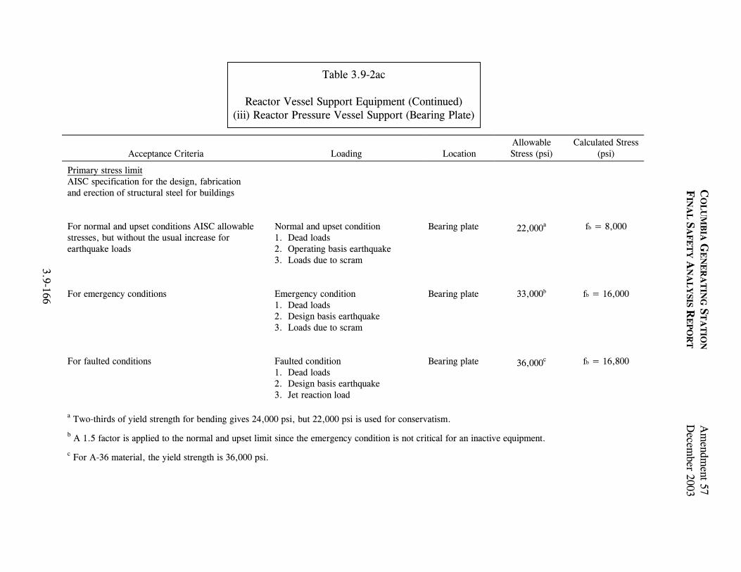
C
OL
UM
BIA
GE
NE
RA
TIN
G S
TA
TIO
N A
mendm
ent 57
FIN
AL
SA
FE
TY
AN
AL
YSIS R
EP
OR
T
Decem
ber 2003
3.9-166
Table 3.9-2ac
Reactor Vessel Support Equipment (Continued) (iii) Reactor Pressure Vessel Support (Bearing Plate)
Acceptance Criteria
Loading
Location Allowable Stress (psi)
Calculated Stress (psi)
Primary stress limit AISC specification for the design, fabrication and erection of structural steel for buildings
For normal and upset conditions AISC allowable stresses, but without the usual increase for earthquake loads
Normal and upset condition 1. Dead loads 2. Operating basis earthquake 3. Loads due to scram
Bearing plate 22,000a fb = 8,000
For emergency conditions Emergency condition 1. Dead loads 2. Design basis earthquake 3. Loads due to scram
Bearing plate 33,000b fb = 16,000
For faulted conditions Faulted condition 1. Dead loads 2. Design basis earthquake 3. Jet reaction load
Bearing plate 36,000c fb = 16,800
a Two-thirds of yield strength for bending gives 24,000 psi, but 22,000 psi is used for conservatism.
b A 1.5 factor is applied to the normal and upset limit since the emergency condition is not critical for an inactive equipment. c For A-36 material, the yield strength is 36,000 psi.

C
OL
UM
BIA
GE
NE
RA
TIN
G S
TA
TIO
N A
mendm
ent 57
FIN
AL
SA
FE
TY
AN
AL
YSIS R
EP
OR
T
Decem
ber 2003
3.9-167
Table 3.9-2ac
Reactor Vessel Support Equipment (Continued) (iv) Stabilizer Bracket-Adjacent Shell
Acceptance Criteria
Loading
Location Allowable Stress
(psi) Calculated Stress (psi)
ASME B and PVC Section III Primary Local Membrane Plus Primary Bending Limit for SA 533 Grade B, Class 1:
For design mechanical load condition:
1.5 x 26,700 = 40,050
Design mechanical load
1. Design earthquake (operating basis earthquake) 2. Design pressure
Local membrane plus bending 40,050 37,635
For faulted and emergency condition:
1.5 Sy = 63,450
Faulted and emergency condition load:
1. Maximum credible earthquake (design basis earthquake) 2. Jet reaction forces 3. Design pressure
Local membrane plus bending 63,450 57,745
Note: Faulted category loads were evaluated with emergency allowable stresses.
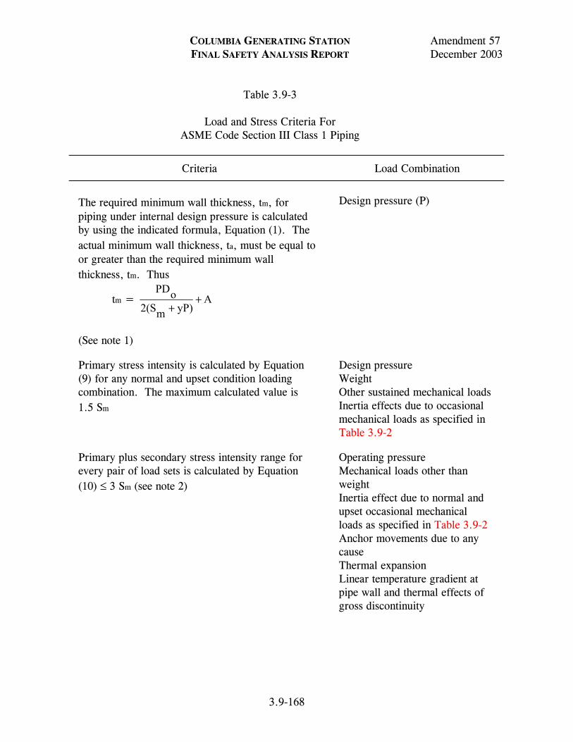
COLUMBIA GENERATING STATION Amendment 57 FINAL SAFETY ANALYSIS REPORT December 2003 Table 3.9-3 Load and Stress Criteria For ASME Code Section III Class 1 Piping
Criteria Load Combination
3.9-168
The required minimum wall thickness, tm, for piping under internal design pressure is calculated by using the indicated formula, Equation (1). The actual minimum wall thickness, ta, must be equal to or greater than the required minimum wall thickness, tm. Thus
tm = AyP)m2(SoPD
++
(See note 1)
Design pressure (P)
Primary stress intensity is calculated by Equation (9) for any normal and upset condition loading combination. The maximum calculated value is 1.5 Sm
Design pressure Weight Other sustained mechanical loads Inertia effects due to occasional mechanical loads as specified in Table 3.9-2
Primary plus secondary stress intensity range for every pair of load sets is calculated by Equation (10) ≤ 3 Sm (see note 2)
Operating pressure Mechanical loads other than weight Inertia effect due to normal and upset occasional mechanical loads as specified in Table 3.9-2 Anchor movements due to any cause Thermal expansion Linear temperature gradient at pipe wall and thermal effects of gross discontinuity

COLUMBIA GENERATING STATION Amendment 57 FINAL SAFETY ANALYSIS REPORT December 2003 Table 3.9-3 Load and Stress Criteria for ASME Code Section III Class 1 Piping (Continued)
Criteria Load Combination
3.9-169
If Equation (10 cannot be satisfied for all load sets, then for those pairs of load sets which do not satisfy Equation 10):
The nominal value of expansion stress is calculated by Equation (12) ≤ 3S m
Thermal anchor movements Thermal expansion
The range of primary plus secondary membrane plus bending stress intensity, excluding thermal bending and thermal expansion stresses, are calculated by Equation (13) ≤ 3Sm
Operating pressure Weight plus other sustained mechanical loads Inertia effect due to normal and upset occasional mechanical loads as specified in Table 3.9-2 Thermal effect of gross discontinuity
For every pair of load sets the peak stress intensity range (Sp) is calculated by Equation (11) due to operating pressure, mechanical loads other than weight, inertia effect of normal upset occasional mechanical loads, anchor movement due to any cause, thermal expansion, temperature gradient at pipe wall, and thermal effects of gross discontinuity. The alternating stress intensity (Salt) is calculated as follows: 1/2 Sp, for every pair of load sets where Equation (10) is satisfied. [(Ke) (1/2) (Sp)], for every pair of loads sets, where Equation (10) cannot be satisfied, but Equations (12) and (13) are satisfied. (Ke) is as defined in NB-3653.6. The appropriate design fatigue curve is used to determine the number of allowable cycles (Ni) corresponding to the alternating stress intensity, for every pair of load sets. The usage factor (Ui), is calculated by taking the expected number of load set cycles (Ni) and dividing this value by (Ni). The cumulative usage factor (U), which is the sum of the individual usage factors (Ui), is calculated

COLUMBIA GENERATING STATION Amendment 57 FINAL SAFETY ANALYSIS REPORT December 2003 Table 3.9-3 Load and Stress Criteria for ASME Code Section III Class 1 Piping (Continued)
Criteria Load Combination
3.9-170
Cumulative Usage Factor (U) ≤ 1.0
The permissible pressure under any emergency condition is shown not to be greater than 1.5 times the design pressure (P)
N/A
The permissible pressure under any faulted condition is shown not to be greater than 2 times the design pressure (P) (see note 3)
N/A
The primary stress intensity is calculated by Equation (9) for any emergency condition loading combination. The maximum calculated value is ≤ 2.25 Sm.
Peak pressure Weight Other sustained mechanical loads Inertia effects due to occasional mechanical loads as specified in Table 3.9-2
The primary stress intensity is calculated by Equation (9) for any faulted condition loading combination (see note 3). The maximum calculated value is ≤ 3.0 Sm.
Pressure Weight Other sustained mechanical loads Inertia effects of occasional mechanical loads as specified in Table 3.9-2
NOTES: 1. All equations and symbols are as defined in ASME Code Section III, Subarticle
NB-3600. 2. This need not be satisfied if the rules of ASME Code Section III, Paragraph
NB-3653.6 are complied with. 3. This need not be satisfied if other rules, as set forth in ASME Code Section III
Appendix F are complied with.

COLUMBIA GENERATING STATION Amendment 57 FINAL SAFETY ANALYSIS REPORT December 2003 Table 3.9-4 Load and Stress Criteria for ASME Code Class 2 and 3 Piping System
Criteria Load Combination
3.9-171
The required minimum wall thickness, tm, for piping under internal design pressure is calculated by using the indicated formula, Equation (3). The actual minimum wall thickness, ta, must be equal to or greater than the required minimum wall thickness, tm. Thus
tm = AyP)m2(SoPD
++
(See notes 1 and 2)
Design pressure (P)
The sum of the longitudinal stresses due to pressure, weight, and sustained loads are calculated by Equation (8) ≤ 1.0 Sh.
Design pressure Weight Other sustained mechanical loads
The sum of the longitudinal stresses due to pressure, weight, sustained loads, and inertia effects of normal and upset occasional loads are calculated by Equation (9) ≤ 1.2 Sh.
Peak pressure (see note 3). Weight Sustained mechanical loads Inertia effects of occasional mechanical loads as specified in Table 3.9-2
The thermal expansion stress range, including effects of anchor displacement due to normal and upset occasional mechanical loads are calculated by Equation (10) ≤ Sa (see note 4).
Thermal expansion Anchor movements due to thermal expansion
The sum of the longitudinal stresses due to pressure, weight, and other sustained loads, plus the thermal expansion stress range, including effects of anchor displacement due to thermal expansion and normal and upset occasional
Design pressure Weight Other sustained mechanical loads Thermal expansion Anchor displacements due to

COLUMBIA GENERATING STATION Amendment 57 FINAL SAFETY ANALYSIS REPORT December 2003 Table 3.9-4 Load and Stress Criteria for ASME Code Class 2 and 3 Piping System (Continued)
Criteria Load Combination
3.9-172
mechanical loads are calculated by Equation (11) ≤ (Sh + Sa) (see note 4).
thermal expansion and normal and upset mechanical loads as specified in Table 3.9-2
The sum of the longitudinal stresses due to pressure, weight, sustained loads, inertia effects of Emergency condition mechanical loads are calculated by Equation (9) ≤ 1.8 Sh.
Design pressure Weight Other sustained mechanical loads Inertia effect of occasional mechanical loads as specified in Table 3.9-2
The sum of the longitudinal stresses due to pressure, weight, sustained loads, inertia effects of faulted condition mechanical loads are calculated by Equation (9) ≤ 2.4 Sh.
Peak pressure (see note 3) Weight Other sustained mechanical loads Inertia effect of occasional mechanical loads as specified in Table 3.9-2
NOTES: 1. All equations and symbols are defined in ASME Code Section III, Subarticle NC-3600. 2. Joint efficiency (E) is as defined in ASME Code Section III, Paragraph ND-3641.1.
For ASME Code Class 2 piping E equal to 1.0 is used. 3. Design pressure may be used if the Design Specification states that peak pressure and
earthquake need not be taken as acting concurrently. 4. The requirements of either Equation (10) or Equation (11) must be met.

Amendment 55May 2001
Typical Relief Valve Transient
990306.79 3.9-1FigureForm No. 960690
Draw. No. Rev.
1800
1600
1400
1200
1000
800
600
400
200
0
400
300
200
100
0
30,000
20,000
10,000
Pres
sure
(psi
a)Fl
uid
Velo
city
(ft/s
ec)
Elbo
w F
orce
(lb)
Time (sec)
00 0.05 0.10 0.15 0.20 0.25 0.30 0.35 0.40 0.45 0.50
Columbia Generating StationFinal Safety Analysis Report

Amendment 55May 2001
Reactor Internals Flow Paths
990306.80 3.9-2FigureForm No. 960690
Draw. No. Rev.
Reactor Core ~ 2/3 Core Height
Diffuser
To RecirculationPump
FloodableVolume
ReactorPrimaryVessel
Core Shroud
Nozzle
Downcomer Flow
Suction Chamber
Throat(MixingSection)
FromRecirculation
Pump
ReactorCore Spray CoolingSpargers
Columbia Generating StationFinal Safety Analysis Report

Amendment 57December 2003
Fuel Support Pieces
990306.81 3.9-3FigureForm No. 960690
Draw. No. Rev.
Center Line of fuel Support
Control Rod Guide Tube
Coolant Flow
Orifice (1 of 4)
Core Plate
Guide tube and Fuel Support Alignment
Orificed Fuel Support
Fuel Assembly
Orifice
Orifice Spring
Core Plate Assembly
Orifice Guide
Peripheral Fuel Support(Non-Removable)
Fuel Assembly
Coolant FlowPeripheral Fuel
Support
Orificed Fuel Support(One Orifice Shown)
Columbia Generating StationFinal Safety Analysis Report
LDCN-02-000

Columbia Generating StationFinal Safety Analysis Report
Draw. No. Rev. Figure
Amendment 58December 2005
Form No. 960690FHLDCN-05-021, 05-023
Jet Pump
990306.82 3.9-4
Diffuser
BWR 5 and 6 have fivenozzle jet pumps,shorter throats
SuctionInlet
BWR 5
Hold DownClamp
DriveNozzle
Inlet RiserPipe
Throat
Inlet
Slip Joint Clamp
Restrainer Bracket

Amendment 55May 2001
Pressure Nodes Used For DepressurizationAnalysis
990306.83 3.9-5FigureForm No. 960690
Draw. No. Rev.
7
6
2 2
1
8
2 2
35
4
9
SteamSeparator
Mixing Plenum
Feedwater
Upper Shroud
Recirc-ulationLine
Break
Recirc Pump
LowerShroud
Lower ShroudSupport
Lower Plenum
CoreSupportAssembly
Rec
ircul
atio
n Lo
op
Bypa
ss
Bypa
ss
Bypa
ss
Fuel
Bun
dle
ShroudHead
Water Level
Steam Dome
Steam DryerSteam Line
IsolationValve
Steam Line Break
Upper Plenum
Top Fuel Guide
Dow
ncom
er
Con
trol R
odG
uide
Tub
e
Rec
ircul
atio
n Lo
op
Jet P
ump
Columbia Generating StationFinal Safety Analysis Report

COLUMBIA GENERATING STATION Amendment 54 FINAL SAFETY ANALYSIS REPORT April 2000
LDCN-99-000 3.10-1
3.10 SEISMIC AND DYNAMIC QUALIFICATION OF SAFETY-RELATED INSTRUMENTATION AND ELECTRICAL EQUIPMENT
3.10.1 SEISMIC AND DYNAMIC QUALIFICATION CRITERIA 3.10.1.1 Safety-Related Equipment Identification The Master Equipment List (MEL) is a computerized database of CGS equipment identification numbers and related information. The Safety Related Mechanical (SRM) list is a subset of MEL which contains all of the mechanical (nonelectrical) equipment which is in engineered safety features and reactor protection systems. The seismic and dynamic qualification of SRM equipment is discussed in Section 3.9.2.2. The equipment on the C1E list, also a subset of MEL, and the equipment necessary for the operators to follow the course of an accident (Regulatory Guide 1.97) are addressed in Section 3.10. The C1E list also includes equipment supporting structures (cabinets, racks, etc.). Class 1E is defined per IEEE 323-1974 as the safety classification of the electric equipment and systems that are essential to emergency reactor shutdown, containment isolation, reactor core cooling, and containment and reactor heat removal, or otherwise are essential in preventing significant release of radioactive material to the environment. All parameters required to perform the qualification evaluation have been determined, including normal and accident operational requirements, operating data, and manufacturer’s data. The location of the equipment has been verified by plant walk down or by plant records, to ensure the appropriateness of the required response spectra (RRS). The C1E list in the MEL includes the Qualification Information and Documentation (QID) file number. The QID file contains the following information:
a. The name of the company or organization which prepared the qualification report,
b. The report identification number and date, c. The complete report (if the reports were proprietary and not released to Energy
Northwest, audits were conducted, and summary reports prepared from the audit),
d. Required input loads or applicable required and test response spectra for the
equipment, e. Normal and accident operational requirements of the equipment,

COLUMBIA GENERATING STATION Amendment 54 FINAL SAFETY ANALYSIS REPORT April 2000
LDCN-99-000 3.10-2
f. The identification of whether the equipment is subject to fatigue due to
hydrodynamic loading, and g. The building location for each piece of equipment.
3.10.1.2 Criteria for Acceptability The original equipment seismic qualification requirement for CGS was described in the Preliminary Safety Analysis Report (PSAR). These requirements specified that the nuclear steam supply system (NSSS) and balance-of-plant (BOP) equipment be designed and tested to good industry practices. IEEE 344-1971 represented the established industry practices at that time and equipment purchases were made to those requirements. In March 1979 Energy Northwest was notified that the NRC would review CGS equipment seismic qualification to upgraded criteria. This criteria was defined as IEEE 344-1975 as supplemented by Regulatory Guides 1.100 and 1.92 and NUREG-0800, Standard Review Plan (SRP) Sections 3.9.2 and 3.10. A complete review (reevaluation) of the seismic/ hydrodynamic load basis, along with reevaluation of past equipment qualification documentation, was performed. Energy Northwest undertook an equipment requalification program to ensure all Class 1E equipment would perform their safety functions during the seismic/hydrodynamic loading conditions postulated to occur at CGS. This program included
a. Identification of Class 1E equipment, b. Definition of seismic and hydrodynamic loads, c. Collection of seismic qualification documentation to current criteria, d. Reevaluation of the seismic qualification documentation to current criteria, e. Identification of document deficiencies, and f. Correction of identified deficiencies.
The NRC staff assembled a Seismic Qualification Review Team (SQRT) and conducted a site audit of the qualification program and equipment installation. All C1E instrumentation and electrical equipment was designed to withstand the effects of the safe shutdown earthquake (SSE) described in Section 3.7.1. The safety-related (Class 1E) instrumentation and electrical equipment were reevaluated to ensure performance of their safety function during and after operating basis earthquakes (OBEs), SSE, and/or the hydrodynamic loads which result from a loss-of-coolant accident (LOCA) or other design-basis event.

COLUMBIA GENERATING STATION Amendment 53 FINAL SAFETY ANALYSIS REPORT November 1998
3.10-3
Suppression pool hydrodynamic loads were developed for the CGS plant and are discussed in the “Plant Design Assessment for SRV and LOCA Loads,” Revision 3 (see Appendix 3A). The safety/relief valve (SRV) building responses are appropriately combined with OBE, SSE, intermediate break accident (IBA), and design-basis accident (DBA) building responses to provide the basis for evaluating acceptability of Class 1E electrical and safety-related mechanical equipment originally qualified to seismic only dynamic loading. Detailed reevaluation of each component of Seismic Category I equipment was performed by comparison of original qualification RRS with revised seismic plus hydrodynamic RRS to demonstrate satisfactory qualification of the equipment. When such comparisons were not sufficient, other means of evaluating the original qualification against the new dynamic load combinations are used. Hydrodynamic loads were limited to equipment located within containment or pipe-mounted equipment located between containment and the first equivalent six-way anchor outside containment. For that equipment, the hydrodynamic response spectra was added by square-root-of-the-sum-of-the-squares (SRSS) to the response due to the SSE computed using the finite element soil-structure interaction analysis to determine adequacy. The use of SRSS methodology for combining response to dynamic loads was justified in Reference 3.10-1. In regard to the load combination SRV1 + SSE + DBA, CGS plant design adequacy assessments for Class 1E electrical equipment were performed on the generic basis established by the BWR Mark II Owner’s Group for this load combination. The equipment affected by hydrodynamic loads were identified and an evaluation documented in the QID files. A list of the equipment was included in the CGS Dynamic Qualification Report (Reference 3.10-2). The equipment located in other buildings was reevaluated for the motion caused by the SSE. That motion is defined by the lumped-mass model analysis described in Section 3.7.2. The reevaluation was based on IEEE 344-1975, as supplemented by Regulatory Guide 1.100 and SRP Section 3.10. There are four exceptions to the use of these criteria:
a. Interim criteria was established to reevaluate equipment mounted on piping systems whose analyses was not completed. The interim criteria was to use the peak of the applicable 0.5% damping floor response spectrum about 8 Hz as input acceleration for analysis or for sine dwell testing. The piping systems were designed, in turn, not to respond to frequencies less than 8 Hz. The as-built piping analyses were subsequently completed using the damping values specified in Regulatory Guide 1.61 or the criteria in ASME Code Case N411. The computed accelerations of the equipment were compared to the interim acceleration criteria to verify that the interim criteria was conservative;

COLUMBIA GENERATING STATION Amendment 53 FINAL SAFETY ANALYSIS REPORT November 1998
3.10-4
b. Equipment which was qualified by testing using single frequency motion was reevaluated using the following criteria to establish its adequacy;
1. If the equipment was rigid [no resonant frequency below the zero period
acceleration (ZPA) of the applicable response spectra] the test input acceleration must be greater than the acceleration corresponding to the ZPA of the response spectrum of the mounting point of the equipment;
2. If the equipment had only one natural frequency, the response
acceleration to the test motion must be calculated at the appropriate damping ratio. To account for cross coupling, the required response acceleration was calculated by multiplying the acceleration corresponding to the equipment’s natural frequency found on the applicable response spectrum by the square root of 2 (1.41). If test response acceleration exceeded the required response acceleration, the test motion was considered adequate for requalification of the equipment;
3. If the equipment had multiple resonant frequencies, it was tested at each
of them. The response to each test was calculated at each resonant frequency. That is, the response to a test at one frequency was calculated at that frequency and at all other resonant frequencies. The responses were then combined using the SRSS method. The test motion was considered adequate if the SRSS of the response accelerations to every test was greater than 1.4 times the SRSS of the accelerations found at the resonant frequencies on the applicable response spectrum;
4. If the equipment had closely spaced modes, the criteria of (3), above,
was used except the responses to the closely spaced modes were combined by the absolute sum rather than SRSS;
c. For equipment which was panel, rack, or duct mounted, the maximum
transmissibility of the mounting system was found by a combination of testing and analysis. The ZPA of the applicable response spectrum was then multiplied by this transmissibility to find the required acceleration for the equipment. Test accelerations of the equipment were then compared with the calculated required acceleration to establish qualification of the equipment; and
d. IEEE 344-1975 references IEEE 323-1974. Section 6.3.5 of IEEE 323-1974
recommends thermal and radiation aging before vibration testing. It has not been shown that normal service condition environmental aging reduces equipment’s ability to withstand a seismic event.

COLUMBIA GENERATING STATION Amendment 61 FINAL SAFETY ANALYSIS REPORT December 2011
LDCN-10-007 3.10-5
The Electric Power Institute (EPRI) conducted testing to confirm that aging has insignificant effects on the ability of electrical and electronic equipment to survive a seismic event. That work is documented in EPRI NP-3326 and NP-5024.
Documentation demonstrating qualification for each item is assembled in QID files. These files provide the details of the qualification method utilized in demonstrating the equipment’s adequacy to function when exposed to seismic/hydrodynamic vibrational input. See Section 3.10.2 for a discussion on methods. 3.10.1.2.1 Cable Tray and Conduit Supports Regardless of cable tray or conduit function, all supports located in Seismic Category I structures are designed to Seismic Category I requirements, with the exception of supports for field routed trays and conduits containing cabling for the communication system and all ac lighting outside of the main control room. All supports are qualified by dynamic analysis using appropriate seismic response spectra. The design considers both dead loads (loads which do not change magnitude and/or position), live loads (loads which do change magnitude and/or position), and SSE acceleration loads. Tray and conduit cable loadings (lb/ft) are accounted for in support design, based on maximum permissible raceway loading for the types of cable utilized. Routing of trays and conduits containing cabling for the communication system and all ac lighting outside of the main control room were reviewed or inspected prior to February 1993 to ensure that failure of the support system cannot result in these trays and conduits having an impact on Class 1E equipment. In February 1993, the installation procedure was changed to ensure future installations of conduit are aligned with engineering standards which define Seismic Category I areas of the plant. Installation requirements are accomplished by using Seismic Category II over I supports and appropriate span lengths. 3.10.1.2.2 Decision Criteria (Original Construction Permit Basis) 3.10.1.2.2.1 Structurally Simple Equipment. See Section 3.7.2.1.9. 3.10.1.2.2.2 Structurally Complex Equipment. Class 1E equipment determined to be structurally complex such that it cannot be described by a simple model may also be qualified by analysis. The equivalent SSE horizontal loads (plus hydrodynamic loads where applicable) are determined using a dynamic model analysis of the equipment represented as a multidegree of freedom system. Horizontal floor response spectra for the particular equipment location and appropriate damping coefficients are used as input to determine the horizontal equipment response. A similar procedure is used to determine the vertical equipment response.

COLUMBIA GENERATING STATION Amendment 61 FINAL SAFETY ANALYSIS REPORT December 2011
3.10-6
3.10.1.2.2.3 Optional Dynamic Testing. In lieu of calculations and analyses, vibration testing of Class 1E equipment is an acceptable method of demonstrating the capability of equipment furnished to meet seismic loading requirements given by the applicable floor response spectra. Test data furnished are either data acquired by testing equipment specifically for CGS or data acquired from previously tested comparable equipment. Dynamic tests were performed in accordance with IEEE 344-1971. (See Section 3.10.1.2.3 for reevaluation to IEEE 344-1975.) 3.10.1.2.2.4 Mandatory Dynamic Testing. When potential failure of Class 1E equipment cannot be evaluated structurally (e.g., opening or closing of electrical circuits), then vibration tests are required to demonstrate seismic adequacy. No analytical procedures are considered acceptable in these instances. 3.10.1.2.2.5 Combined Test-Analysis. Where Class 1E equipment cannot be practically qualified by either analysis or testing alone (due to equipment size, complexity, etc.), a combination test and analysis is required to demonstrate seismic capability. The combination test and analysis were performed in accordance with IEEE 344-1971. (See Section 3.10.1.2.3 for reevaluation to IEEE 344-1975.) 3.10.1.2.3 Reevaluation of Original Seismic Qualification Section 3.10.1.2.2 describes the decision criteria employed in the selection of the qualification method used in the initial equipment specification. As discussed in Section 3.10.1.2, a reevaluation of the original qualification basis and methods employed was required by the NRC. This section discusses the reevaluation decision criteria. 3.10.1.2.3.1 Reevaluation Decision Criteria. The basis and method of qualification for each equipment item was reviewed to determine its adequacy to meet IEEE 344-1975. In addition, requalification to hydrodynamic load conditions was assessed. Original qualification of the equipment generally is in the following categories:
a. Existing documentation fully satisfied existing new loads and criteria. Requalification consists of the preparation of appropriate comparative and certification documents;
b. New dynamic loads or criteria impact the previous qualified status of a
component. Requalification can be completed by providing additional analysis for that component to supplement the original testing or analysis;

COLUMBIA GENERATING STATION Amendment 53 FINAL SAFETY ANALYSIS REPORT November 1998
3.10-7
c. Previous qualification method is not applicable to load criteria now prescribed. For example, a static analysis may have been performed where a dynamic analysis would now be appropriate. Requalification would require proper analysis, test or a combination thereof; and
d. Qualifying documentation consisted of certificates of conformance. In some
cases certificates of conformance did not exist because of equipment relocations or modified safety class determinations. Often, qualifying documentation could be purchased from the manufacturer. If not, requalification would consist of performing proper analysis, test, or a combination thereof.
Qualification procedure methods vary with the nature and load criteria of the equipment and consist of static techniques, dynamic analysis, or test procedures. The following describes these methods. 3.10.1.2.3.2 Static Analysis. Static analysis was allowed for rigid equipment; that is, equipment whose natural frequency is above the ZPA of applicable response spectra. Rigid equipment items are analyzed by static methods which determine forces and moments resulting from center of gravity loading of a lumped mass acted on by the resultant acceleration from multidirectional earthquake motions. Conventional analysis determined stresses and/or deflections at all critical sectional areas, mounting attachment points, and anchor bolts. All stress level findings were additive to operational loads. Structural integrity was established by comparison of stress levels with prescribed codes or manufacturers’ acceptance criteria. Selection of acceleration coefficients was based on response spectra at the equipment item mounting location. Static analysis methods were particularly suited to equipment for which structural integrity is the primary criterion for qualification. Application of static analysis required adequate demonstration that the equipment could be realistically represented by the simple model and that the method produced conservative findings. 3.10.1.2.3.3 Dynamic Analysis. Dynamic analysis methods employed a mathematical model accurately representing the structural mass and stiffness distribution with sufficient degrees of freedom to determine dynamic response to cyclic loadings. These methods were employed when equipment could not be characterized as relatively simple or when interactive effects had to be included in the demonstration of adequacy. Dynamic analysis was also used to qualify equipment for which static analysis methods were too conservative. Detailed dynamic analyses are accomplished with the use of sophisticated computer programs, such as STRUDL, ANSYS, and STARDYNE. The programs require development of a mathematical model that describes the mass and stiffness properties of the equipment. This involves preparation of model geometry, material constants, section properties, boundary conditions, and applied loads for input into the selected computer program. Standard Review

COLUMBIA GENERATING STATION Amendment 53 FINAL SAFETY ANALYSIS REPORT November 1998
3.10-8
Plan Section 3.9.2 modeling guidance is applied. As with static analysis, the results are combined with all other loads acting on or within the equipment item. The use of twice the peak values of the SSE/OBE seismic response spectra to compensate for the inability to realistically model structurally complex equipment was not used in the reevaluation. 3.10.1.2.3.4 Demonstration of Operability By Analysis. Where the function of a component could be demonstrated by analysis alone, analysis was often chosen as the cost-effective method for qualifying mechanical equipment and electric motors. Where structural failure was the only known related failure mode, the allowables and rules of Section III of the ASME Boiler and Pressure Vessel (B&PV) Code were used for pressure retaining ASME materials. For nonpressure boundary materials either the rules and allowables of the AISC Code were used or the ASME Code allowables were extended to nonpressure retaining parts. For ANSI B31.1 components, the allowables and rules of ANSI B31.1 were used. For components which must produce mechanical motion after the faulted condition, the allowables were limited to emergency values for faulted loads. Where the listed codes do not apply (e.g., electric motors), good engineering practice was used to ensure stresses were within the working stress of the material with suitable safety factors. For some components, operability was established by ensuring parts that have relative motion do not come into contact with each other. The manufacturer’s drawings were obtained for those components and the minimum clearances were determined. In order to qualify these components, a deflection analysis was performed at peak load which showed that the parts did not come into contact. Also, it was shown that stress limits were not exceeded. The damping values used in the analyses were those specified in Regulatory Guide 1.61 unless another was justified and documented. In the analyses performed, horizontal and vertical loads are assumed to occur simultaneously in the most unfavorable combinations. Normal operating loads are also combined with the accident loads to produce the most severe stress combination. The “no loss of function” stresses are limited to 90% of the materials minimum yield strength with an SSE added to hydrodynamic loads and the normal operating loads. 3.10.1.2.3.5 Consideration of Fatigue. A fatigue reevaluation was performed for all components for which hydrodynamic loads are significant. To be qualified by analysis the stress levels and number of cycles at that stress are calculated. Then using the methods of ASME Section NB-3222.4, a cumulative damage fraction is calculated. That damage fraction cannot equal or exceed 1.0 for the component to be considered qualified. 3.10.1.2.3.6 Testing Methods. Qualification by testing was required when complex or active equipment could not be efficiently modeled to correctly predict response. The methods employed were laboratory tests conducted to simulated service conditions and in-situ tests conducted in the installed configuration.

COLUMBIA GENERATING STATION Amendment 53 FINAL SAFETY ANALYSIS REPORT November 1998
3.10-9
Dynamic tests are performed to a test response spectrum (TRS) which envelops and closely resembles RRS over the critical frequency range. Equipment was tested to simulated inservice load conditions whenever practical and are appropriately justified when not applied. Operability was verified during and/or after the testing as applicable to the equipment being evaluated. The test specimens were checked for spurious operation during testing. If there were spurious operations, it was determined that they had no detrimental effects on the safety function of the equipment. Spurious operation of relays (e.g., contact chatter) was limited to 2 msec maximum, per IEEE 501-1978 unless it had been demonstrated that the spurious action found would not affect the safety function of the component as applied in its safety system. Multiple frequency, multiple axis testing was used to qualify most of the Class 1E electrical equipment. This testing was performed according to IEEE 344-1975. The equipment was operated before, during, or after the test as required by the system safety function. No functional or structural failure was allowed. Single frequency input motion, such as sine beats, was allowed when (a) the characteristics of the seismic input motion indicated that the motion was dominated by one frequency, (b) the anticipated response of the equipment was adequately represented by one mode, or (c) the test input motion had sufficient intensity and duration to excite all modes to the required amplitudes, such that the testing response spectra envelop the corresponding response spectra of the individual modes. Some equipment was previously qualified to IEEE 344-1971 using single frequency testing. The NRC required that justification be supplied for use of single frequency single axis qualification where the component could respond to multiple modes. These criteria were seldom used to qualify CGS equipment. Justification for those particular cases was made available to the NRC SQRT reviewers during an audit in January 1983 and resolved. Several in-situ test approaches were used to complete qualification. These may be grouped into tests that verify accuracy of the analytical model, verify rigidity, justify reducing stress analysis conservatism, and demonstrate operability under simulated load conditions. This latter test, more appropriately called an in-situ static load test, simulates seismic deflections by means of an appropriately directed static force application. Operability is exhibited before, during, and after application of the deflecting load. Another type of in-situ test was used to qualify components attached to the high-pressure core spray (HPCS) system diesel generator. Large reciprocating engines produce starting and running vibrations to attached components much greater than that received due to seismic acceleration. If it was determined that the acceleration to the component under actual running operation exceeded the calculated input due to seismic effects by a factor of 3, the component was accepted as having sufficient seismic adequacy.

COLUMBIA GENERATING STATION Amendment 54 FINAL SAFETY ANALYSIS REPORT April 2000
LDCN-99-000 3.10-10
3.10.1.2.3.7 Combination of Testing and Analysis. Most qualification of equipment employs a combination of testing and analysis. Sections 3.10.2 and 3.10.3 provide examples of typical equipment qualifications that used this methodology. 3.10.2 METHODS AND PROCEDURES FOR QUALIFYING INSTRUMENTATION
AND ELECTRICAL EQUIPMENT 3.10.2.1 Methods For Qualifying Nuclear Steam Supply System Equipment (Excluding
Motors and Valve-Mounted Equipment)
a. Procedures - GE-supplied Seismic Category I equipment meets the requirements that the seismic qualification should demonstrate the capability to perform the required function during and after the SSE and other postulated events. Both analysis and testing were used, but most equipment was tested. Analysis was primarily used to determine the adequacy of mechanical strength (mounting bolts, etc.) after operating capability was established by testing;
1. Analysis - GE-supplied Safety Class 1E equipment, performing primarily
a mechanical safety function (pressure boundary devices, etc.), was analyzed since the passive nature of their critical safety role usually made testing impractical. Analytical methods described in Section 3.10.1.2.3 and sanctioned by IEEE 344-1971 were utilized in such cases;
2. Testing - GE-supplied Safety Class 1E equipment, having primarily an active electrical safety function, was tested in compliance with IEEE 344-1971, and reevaluated per Section 3.10.1.2.3. Supplemental test data meeting IEEE 344-1975 was obtained when single frequency testing could not be justified; and
b. Documentation - Documentation used to seismically qualify GE-supplied Safety
Class 1E equipment is in accordance with the requirements of IEEE 344-1975. The documentation is maintained in a permanent file by Energy Northwest or GE and is available for audit.
3.10.2.2 Methods For Qualifying Balance-of-Plant Equipment Suppliers of Seismic Category I equipment such as batteries and racks, instrument racks, control consoles, electrical distribution equipment, etc., are required to demonstrate that their components or systems do not suffer loss of function during or after SSE or OBE seismic loading. Tests or analysis are performed in accordance with the criteria described in Section 3.10.1.2.3 and IEEE Standard 344-1975. The magnitude of the SSE and OBE loadings which each component experiences is determined by its location within the plant. The response spectra for the various plant locations are included in each equipment’s QID file

COLUMBIA GENERATING STATION Amendment 53 FINAL SAFETY ANALYSIS REPORT November 1998
3.10-11
and a comparison of the equipment’s qualification and capability is made to the RRS to document its adequacy. 3.10.2.3 General Electric-Supplied Equipment Seismic Analyses and/or Testing Procedures 3.10.2.3.1 Testing Procedures for Qualifying Equipment (Excluding Motors and
Valve-Mounted Equipment) The testing procedure for qualifying electrical equipment and instrumentation (excluding motors and valve-mounted equipment) required that the devices be mounted on the vibration machine table the same way it was to be installed in the plant. The device was tested in the operating states that it would experience in performing its safety functions and these states were monitored before, during, and after the test to ensure proper function and absence of spurious reactions. In the case of a relay, both energized and deenergized states and normally open and normally closed contact configurations were tested if the relay were used in those configurations in its safety functions. The initial seismic qualification of GE-supplied electrical equipment was based on single frequency “continuous” testing in which the applied vibration was a sinusoidal table motion at a fixed peak acceleration and a discrete frequency at any given time. Each frequency and acceleration combination was maintained for about 30 sec except when a resonance search was made (see IEEE 344-1971). The vibratory excitation was applied in three orthogonal axes individually with the axes chosen as those coincident with the most probable mounting configuration. The first step was to search for resonances in each device. This was done since resonances cause amplification of the input vibration and are the most likely cause of malfunction or spurious operation. The resonance search was usually run at low acceleration levels (0.2g) to avoid destroying the test sample in case a severe resonance was encountered. The search was made from 0.25 Hz to 33 Hz in accordance with IEEE 344-1971 for a test period of no less than 7 minutes; if the device was large enough, the vibrations were monitored by accelerometers placed at critical locations from which resonances were determined by comparing the acceleration level with that at the table of the vibration machine. Usually, the devices were either too small for an accelerometer, had their critical parts in an inaccessible location, or had critical parts that would be adversely affected by the mounting of an accelerometer. In these cases, the resonances were detected visually (strobe light), by audible observation, or by performance. Following the frequency scan and resonance determination, the devices were tested to determine their malfunction limit. The malfunction limit test was run at each resonant frequency as determined by the frequency scan. In this test, the acceleration level was gradually increased until either the device malfunctioned or the limit of the vibration machine was reached. If no resonances were detected (as was usually the case), the device was

COLUMBIA GENERATING STATION Amendment 53 FINAL SAFETY ANALYSIS REPORT November 1998
3.10-12
considered to be rigid (all parts move in unison) and the malfunction limit was therefore independent of frequency. To achieve maximum acceleration from the vibration machine, rigid devices were malfunction tested at the upper test frequency (33 Hz,) since that allowed the maximum acceleration to be obtained from deflection-limited machines. Under the reevaluation program described in Section 3.10.1.2.3, the adequacy of the single frequency, single axis testing was reviewed. Supplemental test data, both on full cabinet assemblies and components, were obtained that utilized multifrequency biaxial input motion in accordance with IEEE 344-1975. A complete review of the control room panels and local instrument panels was performed and qualification upgrade to IEEE 344-1975 was achieved (see Section 3.10.3.1). 3.10.2.3.2 Qualification Procedures for Motors Seismic qualification of the emergency core cooling system (ECCS) motors is discussed in Section 3.9.2.2.2.7 in conjunction with the ECCS pump and motor assembly. 3.10.2.3.3 Qualification Procedures for Valve-Mounted Equipment The piping analyses established the response spectra, power spectral density function or time history characteristics, and developed a horizontal and a vertical acceleration for the pipe-mounted equipment. Pipe-mounted valves are normally furnished with a natural frequency greater than or equal to 33 Hz. Amplification of the seismic/hydrodynamic motion through the valve yoke structure was considered in the valve operator qualification. Class 1E motor-operated valve actuators were qualified per IEEE 382-1972, which invokes IEEE 344-1971 for dynamic qualification. Three methods were used to demonstrate operability of the full valve assembly: (a) testing per IEEE 344-1975 criteria of representative samples that included the valve, yoke structure, valve operator, and associated limit switches and solenoids (if air operated), (b) testing of the complete valve assembly, using the in-situ static load test method, and (c) analysis of the valve assembly where the input load was small enough such that only minor deflections of the valve assembly occur and it could be demonstrated that critical parts would not bind up under maximum postulated loads. Section 3.9.2.2.1 provides additional detail on these last two methods. The main steam SRVs, including the electrical components mounted on the valve, were subject to a dynamic seismic test. This testing is described in Sections 3.9.2.2.2.14 and 3.9.3.2.4.2. 3.10.2.4 Balance-of-Plant Equipment Analyses and/or Testing Procedures Descriptions of the various acceptable analyses and/or test procedures, as well as criteria for determining which procedures are applicable to the particular units of equipment or systems, are described in Section 3.10.1.2 and in the reevaluation and upgrade program described in Section 3.10.1.2.3.

COLUMBIA GENERATING STATION Amendment 53 FINAL SAFETY ANALYSIS REPORT November 1998
3.10-13
Seismic qualification by analysis followed the procedures described in Section 3.10.1.2.2. Most electrical equipment was qualified by test. Seismic qualification by testing followed the procedures described in Sections 3.10.1.2.2.3 and 3.10.1.2.2.4 as follows: the specimen is fastened to a test table in a configuration simulating inservice mounting. Generally, a low level resonant search is made, followed by the OBE and SSE tests. Input excitations such as continuous single frequency sinusoidal motions, sine beat motions, are acceptable if justification as discussed in Section 3.10.1.2.3.6 is established. Random motions are used primarily to qualify the equipment. Each horizontal axis is excited separately, then simultaneously with the vertical axis, unless otherwise justified. Where applicable, voltage and current outputs are monitored. Seismic qualification by a combination of test and analysis (where applicable) was performed under the procedures described in Section 3.10.1.2.2.5. Combined test/analysis procedures were often used for large assemblies such as panels, racks, large reciprocating equipment, and large air handling units. Under this procedure, the supporting structure may be analyzed for adequacy and amplification factors and the components tested to the amplified values. Extension of a test on a prototype unit often required additional analysis to extend its results to a family of equipment of similar designs from that manufacturer. 3.10.3 METHODS AND PROCEDURES OF ANALYSIS OR TESTING OF SUPPORTS
FOR INSTRUMENTATION AND ELECTRICAL EQUIPMENT 3.10.3.1 Nuclear Steam Supply System Equipment (Other Than Motors and Valve-Mounted
Equipment) The Class 1E equipment supplied by GE is used in many systems on many different plants under widely varying seismic requirements. The seismic qualification tests were performed at all frequencies from 5 Hz to 33 Hz (the required qualification range was 0.25 Hz to 33 Hz but since test facility capability usually limited the lower frequency test to 5 Hz, a combination of test and analysis was used to ensure there were no untested lower resonances). A sample analysis is located in Appendix 3.10C. Some GE-supplied support structures that contain Class 1E devices were qualified by analysis. A procedure of such analysis is discussed in Appendix 3.10A. Analysis was used for passive mechanical devices and was also used in combination with testing for larger assemblies containing Class 1E devices. For instance, a test might have been run to determine if there were natural frequencies in the equipment within the critical seismic frequency range (see IEEE 344-1975). If the equipment was determined to be free of natural frequencies, then it was assumed to be rigid and a static analysis was performed. A sample static analysis is discussed in Appendix 3.10B (see IEEE 344-1975). If it had natural frequencies in the critical frequency range, then calculations of transmissibility and responses to varying input accelerations were determined to see if Class 1E devices mounted in the assembly would operate without malfunctioning.

COLUMBIA GENERATING STATION Amendment 53 FINAL SAFETY ANALYSIS REPORT November 1998
3.10-14
In general, the testing of Class 1E equipment was accomplished using the following procedure. Assemblies (i.e., control panels) containing devices which have had seismic malfunction limits established were tested by mounting the assembly on the table of a vibration machine in the manner it was to be mounted when in use. The vibration testing was performed by running a low level resonance search. The assemblies were tested in the three major orthogonal axes. The resonance search was run in the same manner as described for devices (see Section 3.10.2.3.1). If resonances were present, a transmissibility between the input and the location of each Seismic Category I device was determined by measuring the accelerations throughout the structure and calculating the magnification between it and the input. Once known, the transmissibilities could be used analytically to determine the response at any Seismic Category I device location for any given input. It was assumed that the transmissibilities were linear as a function of acceleration even though they actually decrease as acceleration is increased. Therefore, the assumption is conservative. Since control panels and racks constitute the majority of Class 1E electric assemblies supplied by GE, seismic qualification testing of these will be discussed in more detail. The four generic panel types considered include vertical boards, instrument racks, local racks, and National Electrical Manufacturers Association (NEMA) type 12 enclosures. One or more of each type was tested using the above procedures. Figures 3.10-1 through 3.10-4 illustrate the four basic panel types referenced above and show typical accelerometer locations. For each of the control room panels and local instrument racks a transmissibility map was established by testing, analysis, or similarity with tested panel bench boards. Required acceleration levels were established for zones within the panels. Class 1E electrical device locations were determined through design review of panel drawings and plant inspections. Required acceleration levels were then established for each device within the panel. Then this required level was compared to the level the device received during full level assembly tests or individual device tests to ensure devices received sufficient testing to demonstrate their adequacy in their installed locations. 3.10.3.2 Balance-of-Plant Supports Battery racks, instrument racks, cabinets, panels, and cable trays were originally specified to be qualified in accordance with IEEE 344-1971. Response spectra for all locations where the equipment is to be mounted were specified to the vendor. Subsequently, all original qualification programs were reviewed and reevaluated using IEEE 344-1975. Cable trays, raceways, and support systems were furnished and installed by the electrical contractor in accordance with specified criteria and qualification procedures. A complete set of floor response spectra was provided to the contractor who was required to perform an analysis of the raceways and supports. This included trays and conduits, horizontal shelf members, vertical support members, internal bracing members, lateral or longitudinal

COLUMBIA GENERATING STATION Amendment 54 FINAL SAFETY ANALYSIS REPORT April 2000
LDCN-99-000 3.10-15
supports, and all connections. The contractor determined seismic forces based on specified levels of acceleration and frequency for each building and elevation. Maximum tray and conduit loading, minimum structural properties, as well as specified maximum spacing of supports and stress limits, are specified to the vendor. Limitations are also placed on stresses in supports to steel and to concrete. The contractor was required to submit all calculations of the seismic analysis and design for review and approval to demonstrate qualification. 3.10.4 OPERATING LICENSE REVIEW This section discusses Energy Northwest’s Seismic/Hydrodynamic Equipment Qualifications Program Results. This program has established seismic/hydrodynamic vibratory service conditions and detailed documentation of the qualification of safety-related electrical equipment, all contained in the QID files. The results of the reevaluation program and the NRC’s audit of the adequacy of the qualification methods and results of the reevaluation program are also discussed. 3.10.4.1 Establishment of Service Conditions The original service condition basis, which was seismic and operational loads has been augmented with vibrational loads due to event-induced loads, including SRV discharge, small break accident (SBA), IBA, and DBA as applicable. These loads include chugging, pool swell, drag loads, annulus pressurization, etc. These hydrodynamic loads have been established and factored into the load definition for safety-related equipment. Energy Northwest has submitted analyses justifying the combination methodology and the plant areas affected by the loads to the NRC. The load basis for dynamic qualification of electrical equipment was reviewed and accepted by the NRC. Sections 3.7 and 3.9 provide the details of the methodology used and the load results. NUREG-0892 Supplement 1 and Supplement 4 discuss the NRC acceptance of the CGS hydrodynamic loads. Service conditions which include load definition and levels, and normal and accident operating conditions, are established for each safety-related electrical equipment and are contained in QID files. 3.10.4.2 Establishment of Qualification Information and Documentation Files The QID files provide the details of the qualification method and results for each equipment item on the safety-related electrical equipment list. These files are the centralized collection and evaluation location for the documentation that demonstrates the equipment’s qualification. Each item on the safety-related equipment list references this central file and qualification information is easily retrievable. Included in these files is a comparison of the dynamic service conditions and the qualification levels. Test reports, analyses, qualification summary checklists, and data to verify installation similarity to qualified conditions are also included in the QID files.
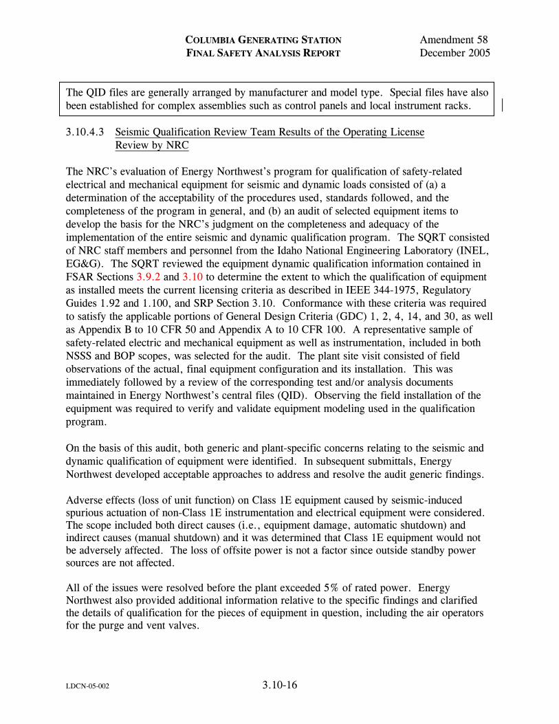
COLUMBIA GENERATING STATION Amendment 58 FINAL SAFETY ANALYSIS REPORT December 2005
LDCN-05-002 3.10-16
The QID files are generally arranged by manufacturer and model type. Special files have also been established for complex assemblies such as control panels and local instrument racks. 3.10.4.3 Seismic Qualification Review Team Results of the Operating License Review by NRC The NRC’s evaluation of Energy Northwest’s program for qualification of safety-related electrical and mechanical equipment for seismic and dynamic loads consisted of (a) a determination of the acceptability of the procedures used, standards followed, and the completeness of the program in general, and (b) an audit of selected equipment items to develop the basis for the NRC’s judgment on the completeness and adequacy of the implementation of the entire seismic and dynamic qualification program. The SQRT consisted of NRC staff members and personnel from the Idaho National Engineering Laboratory (INEL, EG&G). The SQRT reviewed the equipment dynamic qualification information contained in FSAR Sections 3.9.2 and 3.10 to determine the extent to which the qualification of equipment as installed meets the current licensing criteria as described in IEEE 344-1975, Regulatory Guides 1.92 and 1.100, and SRP Section 3.10. Conformance with these criteria was required to satisfy the applicable portions of General Design Criteria (GDC) 1, 2, 4, 14, and 30, as well as Appendix B to 10 CFR 50 and Appendix A to 10 CFR 100. A representative sample of safety-related electric and mechanical equipment as well as instrumentation, included in both NSSS and BOP scopes, was selected for the audit. The plant site visit consisted of field observations of the actual, final equipment configuration and its installation. This was immediately followed by a review of the corresponding test and/or analysis documents maintained in Energy Northwest’s central files (QID). Observing the field installation of the equipment was required to verify and validate equipment modeling used in the qualification program. On the basis of this audit, both generic and plant-specific concerns relating to the seismic and dynamic qualification of equipment were identified. In subsequent submittals, Energy Northwest developed acceptable approaches to address and resolve the audit generic findings. Adverse effects (loss of unit function) on Class 1E equipment caused by seismic-induced spurious actuation of non-Class 1E instrumentation and electrical equipment were considered. The scope included both direct causes (i.e., equipment damage, automatic shutdown) and indirect causes (manual shutdown) and it was determined that Class 1E equipment would not be adversely affected. The loss of offsite power is not a factor since outside standby power sources are not affected. All of the issues were resolved before the plant exceeded 5% of rated power. Energy Northwest also provided additional information relative to the specific findings and clarified the details of qualification for the pieces of equipment in question, including the air operators for the purge and vent valves.

COLUMBIA GENERATING STATION Amendment 60 FINAL SAFETY ANALYSIS REPORT December 2009
LDCN-09-011 3.10-17
3.10.4.4 Pump and Valve Operability Review Team Audit Results of the Operating License Review by NRC
To ensure that Energy Northwest provided an adequate program for qualifying safety-related pumps and valves to operate under normal and accident conditions, the NRC staff performed a two-step review. First, the NRC reviewed FSAR Section 3.9.3.2, the description of Energy Northwest’s pump and valve operability assurance program, and compared it to SRP Section 3.10. Second, the Pump and Valve Operability Review Team (PVORT) conducted an onsite audit of a small representative sample of safety-related pumps and valves supporting documentation. The onsite audit included:
a. A plant inspection to observe the as-built configuration and installation of the equipment,
b. A discussion of the system in which the pump and valve are located, c. Examination of the normal and accident conditions under which the component
must operate, and d. A review of the qualification documentation (stress reports, test reports, etc).
The two-step review was performed to determine the extent to which the qualification of equipment, as installed, meets the current licensing criteria as described in SRP Section 3.10 and conformance with GDC 1, 2, 4, 14, and 30 and Appendix B to 10 CFR 50. 3.10.5 ESTABLISHMENT OF OPERATIONAL PHASE SEISMIC QUALIFICATION
PROGRAM The operational phase program for maintaining qualification of the equipment and the ongoing process of ensuring that qualified equipment is selected for plant design changes is described in the following. Energy Northwest has established an operational phase seismic qualification program. This program is integrated with design changes to Columbia Generating Station to ensure compliance with the criteria as described in IEEE 344-1975, Regulatory Guide 1.100, 1.92, and SRP Section 3.10. Conformance to these criteria as clarified in Sections 1.8.2 and 1.8.3 ensures continuing adequacy to meet the applicable portions of GDC 1, 2, 4, 14, and 30, Appendix B to 10 CFR 50, and Appendix A to 10 CFR 100. The operational phase qualification program is applicable for all design changes that add, modify, or delete safety-related equipment.

COLUMBIA GENERATING STATION Amendment 56 FINAL SAFETY ANALYSIS REPORT December 2001
LDCN-00-099 3.10-18
Design control procedures establish a special qualification review as part of the design change package preparation. Adequacy of the equipment selected to be added to the plant in the design change is assessed and documented to an “as designed” qualification status. Special procurement requirements are detailed for the purchase order. During and after installation, inspections are conducted by Quality Control to ensure that critical attributes of the final installation conforms to the design package. Documentation of qualification is established in the QID files. For design changes that modify or reclassify existing plant equipment or support structures for safety-related equipment, a special review is also required similar to the above preprocurement review. Documentation of qualification is established in QID files. For design changes that delete existing plant equipment or downgrade its safety-related status, a special review is also conducted. Modification of the QID file is considered optional under the program. Component model or part changes that do not affect the function or capability of a component are not considered design changes. Substitutions that have a potential to affect dynamic qualification are evaluated and if necessary qualification is documented in the QID files prior to approval of the substitution. Design control procedures also require the safety-related equipment list in the MEL to be kept current with actual plant configuration as part of the operational phase program. Thus, the link with the plant equipment configuration and qualification documentation (QID files) is maintained throughout plant life. 3.10.6 REFERENCES 3.10-1 Letter from Supply System to NRC, Subject: “Applicability of the Use of the
Square Root of the Sum of the Squares Method for Combining Peak Dynamic Responses to Dynamic Loads for WNP-2” (GO2-83-090).
3.10-2 J.L. Sullivan and D.A. Armstrong, “WNP-2 Dynamic Qualification Report for
Safety-Related Equipment,” Engineering Report, Vols. I and II, October 5, 1982 (historical).

Amendment 55May 2001
Typical Vertical Board
990306.84 3.10-1FigureForm No. 960690
Draw. No. Rev.
Accelerometer Locations
NOTE: Benchboard would be the same with a bench section protruding out approximately half-way down
Columbia Generating StationFinal Safety Analysis Report

Amendment 55May 2001
Typical Instrument Rack
990306.85 3.10-2FigureForm No. 960690
Draw. No. Rev.
Note: Cabinet would contain gages or other special instruments instead of simply drawer type instruments.
Columbia Generating StationFinal Safety Analysis Report

Amendment 55May 2001
Typical Local Rack
990306.86 3.10-3FigureForm No. 960690
Draw. No. Rev.
Note: Piping and other externalconnections not shown
Columbia Generating StationFinal Safety Analysis Report

Amendment 55May 2001
Typical NEMA Type 12 Enclosure
990306.87 3.10-4FigureForm No. 960690
Draw. No. Rev.
Note: Instruments mounted inside oninternal membrane mounted on standoffsattached to back.
Columbia Generating StationFinal Safety Analysis Report

COLUMBIA GENERATING STATION Amendment 53 FINAL SAFETY ANALYSIS REPORT November 1998
3.10A-1
APPENDIX 3.10A DYNAMIC ANALYSIS BY RESPONSE SPECTRUM METHOD FOR NUCLEAR STEAM SUPPLY SYSTEM EQUIPMENT The italicized information is historical and was provided to support the application for an operating license. Appendix 3.10A DYNAMIC ANALYSIS BY RESPONSE SPECTRUM METHOD FOR NUCLEAR STEAM SUPPLY SYSTEM EQUIPMENT TABLE OF CONTENTS 3.10A DYNAMIC ANALYSIS BY RESPONSE SPECTRUM METHOD FOR NUCLEAR STEAM SUPPLY SYSTEM EQUIPMENT ................................................................3.10A-2 3.10A.1 UNCOUPLING THE EQUATION OF MOTION ......................3.10A-2 3.10A.1.1 Method ........................................................................3.10A-2 3.10A.1.2 Assumptions ..................................................................3.10A-3 3.10A.2 MAXIMUM PHYSICAL DISPLACEMENT AND MAXIMUM LOAD RESPONSE ..........................................3.10A-3 3.10A.3 MAXIMUM ACCELERATIONS...........................................3.10A-5

COLUMBIA GENERATING STATION Amendment 53 FINAL SAFETY ANALYSIS REPORT November 1998
3.10A-2
Appendix 3.10A 3.10A DYNAMIC ANALYSIS BY RESPONSE SPECTRUM METHOD FOR NSSS
EQUIPMENT 3.10A.1 UNCOUPLING THE EQUATION OF MOTION 3.10A.1.1 Method The system stiffness and mass matrices are generated using standard techniques. A seismic analysis is performed using the following equations of motion and procedure to uncouple these equations: The equations of motion in matrix form are as follows:
M X Y C ( && && ) &+ + X + K X = 0 (1) where
M = mass matrix, n x n (this includes the hydrodynamic mass) X = column vector of displacement relative to ground* (n x 1) C = damping matrix (n x n) K = stiffness matrix (n x n) Y = column vector of ground accelerations (n x 1) . = first derivative with respect to time . . = second derivative with respect to time
It should be noted that for equipment containing fluid, a hydrodynamic mass coupling exists between real structural masses. This hydrodynamic mass appears as diagonal and off-diagonal terms in the mass matrix. The overall system stiffness matrix K is determined by either the matrix force method or the matrix displacement method. The resulting stiffness matrix is similar. Removing the driving-point acceleration vector to the right side of equation (1), the equation reduces to the classical form: M X C&& && &&+ X + K X = -MY (2)

COLUMBIA GENERATING STATION Amendment 53 FINAL SAFETY ANALYSIS REPORT November 1998
3.10A-3
In order to uncouple equation (2), we set:
X = φq (3) Equation (2) then becomes
M q C q K q MYφ φ φ+ + = − && (4)
Pre-multiplying (4) by φT, the transpose of φ, and performing the coordinate transformation described in (4) such that f is defined by the following orthogonality conditions:
φT Mφ = I (5)
φ φ ωTK = 2 (6)
where I is an identify matrix (Nxn) and ω² is a diagonal matrix of the eigenvalues. Then (4) becomes
φ φ φ φ φ φ φT T T TM q C q K q MY&& & &&+ + = − (7)
&& & &&q C q MYT T+ = = −φ φ ω φ2 q (8) 3.10A.1.2 Assumptions The above procedure for uncoupling the equation of motion by using the modal matrix of the undamped system assumes that damping in the system is small. It will further be assumed that the damping matrix C is such that φ+TCφ is a diagonal matrix. The elements of this diagonal-matrix are the modal damping values. 3.10A.2 MAXIMUM PHYSICAL DISPLACEMENT AND MAXIMUM LOAD RESPONSE With the assumptions of 3.10A.1.2, equation (8) may be written in the following uncoupled form:
&& & & &&q q q Si i i i+ + =2 2 Ui i gβ ω ω
i = 1, 2, --- n (9)

COLUMBIA GENERATING STATION Amendment 53 FINAL SAFETY ANALYSIS REPORT November 1998
3.10A-4
where
x
xx
x
i
i
i
ni
i
i
ni
=
=
1
2
1
2....
.
.
.
.
iφ
φφ
φ The maximum physical displacement for each mass is then taken to the square root of the sums of the squares of each of the maximum displacement responses for each mode, i.e.,
( )max , ,/
X imum xij
j
n
=
=
=∑ 2
1
1 2
1 i 2, ..., m
where (X) maximum is the column vector of maximum displacements. Similarly, the maximum load response for the i+th mode is found from
L X
L
LL
L
ji j i
ji
i
i
mi
=
=
β1
2...
where
βj is the stress matrix for element j, j=1, ... m m = total number of elements.
where
βi = damping ratio for the i+th mode expressed as percent of critical damping ωi = ith natural angular frequency of the system Si = modal participation factor the ith mode = -φi
t MD

COLUMBIA GENERATING STATION Amendment 53 FINAL SAFETY ANALYSIS REPORT November 1998
3.10A-5
Ug = ground or floor acceleration time history φi
t = transpose of the ith mode shape D = earthquake direction vector
The response is calculated using the response spectra specified for the location of the input to the analytical model. The analytical procedure is described briefly in the following paragraphs. The system of one-degree-of-freedom equations represented by equation (8) or (9) can be solved by the response spectrum method. With this method, the maximum modal response for each natural frequency of interest is found from the applicable response spectra. Response spectrum curves are essentially plots of the maximum responses of single-degrees-of freedom systems described by equation (9) with Si = 1.0 as a function of their natural frequencies. Having found the maximum modal displacements q, i = 1...m, the maximum physical displacement for the i+th mode is given by:
Xi = φi Si qi The maximum load response is taken to be the square root of the sums of the squares of each of the maximum responses for each mode, i.e.,
( )max , ,/
L imum jj jii
n
=
=
=∑ L 2,..., m2
1
1 2
1
where (L) maximum is the column vector of maximum loads. 3.10A.3 MAXIMUM ACCELERATIONS The accelerations for each mode are determined by multiplying the displacements vector for that mode (Xi) by the natural frequency (ωi²) of that mode.
Ai = Xi ωi² The maximum accelerations are then determined by
( )max/
A imumi
n
=
=∑ A
i2
1
1 2

COLUMBIA GENERATING STATION Amendment 57 FINAL SAFETY ANALYSIS REPORT December 2003
LDCN-02-000 3.10B-1
Appendix 3.10B SAMPLE SEISMIC STATIC ANALYSIS FOR NUCLEAR STEAM SUPPLY SYSTEM EQUIPMENT TABLE OF CONTENTS 3.10B.1 STATIC SEISMIC ANALYSIS OF STANDARD ENCLOSURES.............................................................3.10B-4 3.10B.2 ASSUMPTIONS AND EQUATIONS FOR THE CALCULATION OF MAXIMUM NORMAL AND SHEAR STRESSES IN ENCLOSURE MOUNTING BOLTS..................3.10B-4 3.10B.3 VERIFICATION OF MOUNTING BOLT SEISMIC WITHSTAND CAPABILITY .............................................3.10B-8 3.10B.3.1 Purpose .....................................................................3.10B-8 3.10B.3.2 Scope ........................................................................3.10B-8 3.10B.3.3 Discussion ..................................................................3.10B-8 3.10B.3.4 Conclusion..................................................................3.10B-11 3.10B.4 REFERENCES .............................................................3.10B-11

COLUMBIA GENERATING STATION Amendment 57 FINAL SAFETY ANALYSIS REPORT December 2003
LDCN-02-000 3.10B-2
Appendix 3.10B SAMPLE SEISMIC STATIC ANALYSIS FOR NUCLEAR STEAM SUPPLY SYSTEM EQUIPMENT LIST OF TABLES Number Title Page 3.10B-1 Standard Enclosures 3.10B-12

COLUMBIA GENERATING STATION Amendment 53 FINAL SAFETY ANALYSIS REPORT November 1998
3.10B-3
Appendix 3.10B SAMPLE SEISMIC STATIC ANALYSIS FOR NUCLEAR STEAM SUPPLY SYSTEM EQUIPMENT LIST OF FIGURES Number Title 3.10B-1 Maximum Safe Weight Per Bolt For Standard Enclosure as a Function of the Height of the Center of Gravity
COLUMBIA GENERATING STATION Amendment 53 FINAL SAFETY ANALYSIS REPORT November 1998
3.10B-4
Appendix 3.10B SAMPLE SEISMIC STATIC ANALYSIS FOR NUCLEAR STEAM SUPPLY SYSTEM EQUIPMENT 3.10B.1 STATIC SEISMIC ANALYSIS OF STANDARD ENCLOSURES Presented herein is a set of curves from which static seismic analysis of standard enclosures can be quickly performed. A standard enclosure is any enclosure listed in the Enclosure Standards Manual. The enclosures are assumed to be floor mounted, using all mounting holes with 5/8 in. steel bolts or studs each having an effective area of 0.2256 in2. Using an elastic limit of one half the ultimate strength, the bolts are assumed to have a maximum safe tension stress and maximum safe shear stress of 28,000 psi and 21,000 psi, respectively. The curves are based on a design basis earthquake having a horizontal acceleration of 1.5g and a vertical acceleration of 0.5g. It is assumed that each enclosure is mounted alone and not coupled directly to any other enclosure. The static analysis consists of determining the maximum allowable safe weight of the enclosure and its components for which the mounting bolt stresses are not exceeded. The curves of Figure 3.10B-1 have been derived for this purpose. To use the curves given in Figure 3.10B-1, first determine from Table 3.10B-1 the curve designation of the enclosure being considered. Next, using the corresponding curve in Figure 3.10B-1, determine the maximum safe weight per bolt for a given height of the center of gravity. The maximum safe enclosure weight is then determined by multiplying the weight per bolt by the total number of enclosure mounting bolts. Comparison with the actual weight of the enclosure and its components then indicates whether or not the mounting bolt stresses are exceeded. If the comparison shows that the maximum safe weight per bolt is exceeded, steps should be taken to increase the effective bolt area by welding the enclosure to its mounting, increasing the number of mounting bolts, adding top braces to a wall, or using another appropriate method to ensure safe operation during seismic disturbance. 3.10B.2 ASSUMPTIONS AND EQUATIONS FOR THE CALCULATION OF MAXIMUM NORMAL AND SHEAR STRESSES IN ENCLOSURE MOUNTING BOLTS For the calculation of the maximum normal and shear stresses in the mounting bolts of any enclosure under seismic disturbance, the following necessary assumptions and conventions are made:
a. The enclosure under consideration is assumed to be a rigid body in equilibrium with respect to its mounting.
b. The forces on the enclosure due to seismic accelerations are assumed to act
through the enclosure's center of gravity.

COLUMBIA GENERATING STATION Amendment 53 FINAL SAFETY ANALYSIS REPORT November 1998
3.10B-5
c. The enclosure is assumed to have a known weight W as well as a known center of gravity located at X, Y, Z with respect to a right-handed coordinate system.
d. The right-handed coordinate system is arbitrarily assumed to be located at the
front left-hand lower corner of the enclosure with the positive X-axis to the right along the front edge, the positive Y-axis toward the back of the enclosure, and the positive Z-axis toward the top of the enclosure.
e. The stresses on the enclosure mounting bolts are assumed to be greatest when
the horizontal component of the floor acceleration is perpendicular to a side of the enclosure and the vertical component of the acceleration is downward.
f. It is assumed that the enclosure tends to rotate about an axis parallel to either
the X-axis or the Y-axis, dependent upon the direction of the horizontal acceleration. The location of the axis of rotation is dependent upon the mounting configuration of the enclosure.
g. There is assumed to be no friction between the enclosure and its mounting. h. The horizontal shear force due to the horizontal component of the acceleration is
assumed to be distributed equally among the mounting bolts. i. All mounting bolts are assumed to be identical.
The following procedure outlines the equations involved in determining the mounting bolt stresses. From the geometric configuration of the mounting bolts it is found that the tension forces in the bolts are related by
Fdd
Fii
jj= (1)
where Fi and Fj are the tension forces acting on the i-th and the j-th bolts, respectively, and di
and dj are the perpendicular distances of the i-th and the j-th bolts, respectively, from the axis about which the enclosure tends to rotate. When the enclosure is mounted directly to the floor, the axis of rotation will be an edge of the enclosure. For other mounting configurations, care must be exercised in determining this axis. Summing moments about the enclosure's axis of rotation, the equation relating the unknown bolt tension forces to known quantities is found to be
F1 d1 + F2 d2+ . . . + FN dN = W[A1 . Z + (A2-1)L] (2)

COLUMBIA GENERATING STATION Amendment 53 FINAL SAFETY ANALYSIS REPORT November 1998
3.10B-6
where N is the number of mounting bolts, A1 and A2 are the relative magnitudes of the horizontal and vertical components of the floor acceleration, respectively, and L is the perpendicular distance between the line of action of the vertical acceleration through the center of gravity and the axis about which the enclosure tends to rotate. Substituting (1) into (2), the j-th tension force is
( )[ ]Fd W A Z A L
d d dj
j
N=
⋅ + −
+ + ⋅ ⋅ ⋅ +
. 1 2 1
12
22 2
(3) The other tension forces are determined using Equation (1). The tension stress Ti is related to the tension force by
TFAi
i= (4)
Where A is the effective cross-sectional area of a mounting bolt. Summing forces in the direction of the horizontal force acting upon the enclosure and making use of assumptions 7 and 8, the shear stress on the i-th bolt is
S W AN Ai =⋅⋅
1 (5)
Due to the combined tension and shear stresses, the maximum tension stress, (Ti)max; and the maximum shear stress, (Si)max, present in the i-th bolt are (1):
( )( )maxTT T
Sii
i= +
+2 2
12
2
(6) and
( )( )maxST
Sii
i=
+2
22
(7) To apply the above equations to determine the maximum tension and shear stresses, the following is required:
Total Weight W (pounds)

COLUMBIA GENERATING STATION Amendment 53 FINAL SAFETY ANALYSIS REPORT November 1998
3.10B-7
Center of Gravity X, Y, Z (in.) Horizontal Seismic Acceleration A1(G) Vertical Seismic Acceleration A2(G) Distance to CG (see eq. (2)) L (in.) Number of Bolts N Area Each Bolt A (in.2) Bolt distance from Axis dI, d2 . . . dN(in.) * of Rotation
The procedure to be used as follows:
a. Determine the axis about which the cabinet tends to rotate for a given floor motion.
b. Determine, using Equation (3), the tension force acting on the j-th mounting
bolts (arbitrarily choose one). c. Determine the tension forces acting on the remaining mounting bolts from
application of Equation (1). d. Calculate the tension stress acting on each bolt using Equation (4) and the
results of Step 3. e. Calculate the horizontal shear stress from Equation (5). f. Determine the maximum tension stresses using Equation (6) and the results of
Steps 4 and 5. g. Determine the maximum shear stresses using Equation (7) and the results of
Steps 4 and 5. h. Compare these maximum stresses and allowable stresses of one half the ultimate
strength (in PSI) for the bolt material.

COLUMBIA GENERATING STATION Amendment 53 FINAL SAFETY ANALYSIS REPORT November 1998
3.10B-8
3.10B.3 VERIFICATION OF MOUNTING BOLT SEISMIC WITHSTAND CAPABILITY 3.10B.3.1 Purpose The purpose of the sample analysis is to document a particular static seismic analysis which was performed to verify that the mounting bolts of the standard cabinets are capable of withstanding seismic environment. 3.10B.3.2 Scope The scope of this sample analysis is limited to the static analysis of the mounting bolt stresses of five (5) standard cabinets. The standard cabinets are:
a. Area Radiation Monitor, 236x400 (911) b. TIP Control, 236x401 (913) c. Start-up Neutron Monitor, 236x402 (936) d. Power Range Monitor, 236x403 (937) e. Rod Position Information System, 236x404 (927)
3.10B.3.3 Discussion GE Seismic Design Guide, 225A4582, was used in conducting the static seismic analysis. Each cabinet was assumed to be floor mounted using 5/8 in. bolts in all mounting holes. The maximum safe tension stress and maximum safe shear stress were assumed to be 28,000 psi and 21,000 psi, respectively (equal to one-half the ultimate strength as given in Machinery’s Handbook, Fourteenth Edition). The design basis earthquake was assumed to have a horizontal acceleration of 1.5g and a vertical acceleration of 0.5g. The weight of each cabinet was estimated using the weight of each major component listed in the parts lists for each cabinet. The height of the center of gravity of each cabinet was calculated using the weight and center of gravity of each of the major components. The following includes the necessary information for determining the factor of safety for each cabinet: Cabinet Name: Area Radiation Monitor 236x400
Applied Horizontal Acceleration 1.5g Applied Vertical Acceleration 0.5g Tension Stress (Maximum Safe) 28,000 psi Shear Stress (Maximum Safe) 21,000 psi Weight of Cabinet 675 lb

COLUMBIA GENERATING STATION Amendment 53 FINAL SAFETY ANALYSIS REPORT November 1998
3.10B-9
Number of Mounting Bolts 4 Height of Center of Gravity 48 in. Maximum Allowable Weight Per Bolt 830 lb/bolt (From Curve No. C1 on Page 8 of Seismic Design Guide 225A4582) Maximum Allowable Cabinet Weight
830 lbs/bolt * 4 bolts = 3320 lb
Factor of Safety Maximum Allowable WeightWeight
= = 4 9.
Cabinet Name: TIP Control, 236x401 (913)
Applied Horizontal Acceleration 1.5g Applied vertical Acceleration 0.5g Tension Stress (Maximum Safe) 28,000 psi Shear Stress (Maximum Safe) 21,000 psi Weight of Cabinet 755 lb Number of Mounting Bolts 8 Height of Center of Gravity 50 in. Maximum Allowable Weight Per Bolt 1110 lb (From Curve No. C3 on Page 8 of Seismic Design Guide, 225A4582) Maximum Allowable Cabinet Weight
1110 lbs/bolt * 8 bolts = 8,880 lb
Factor of Safety Maximum Allowable WeightWeight
= = 11 7.
Cabinet Name: Start-Up Neutron Monitor, 236x402 (936)
Applied Horizontal Acceleration 1.5g

COLUMBIA GENERATING STATION Amendment 53 FINAL SAFETY ANALYSIS REPORT November 1998
3.10B-10
Applied Vertical Acceleration 0.5g Tension Stress (Maximum Safe) 28,000 psi Shear Stress (Maximum Safe) 21,000 psi Weight of Cabinet 1910 lbs. Number of Mounting Bolts 12 Height of Center of Gravity 50 in. Maximum Allowable Weight Per Bolt 1110 lb/bolt (From Curves No. C3 on Page 8 of Seismic Design Guide, 225A4582) Maximum Allowable Cabinet Weight 1110 lbs/bolt * 12 bolts = 13,320 lb
Factor of Safety Maximum Allowable WeightWeight
= = 11 9.
Cabinet Name: Power Range Monitor, 236x403 (937)
Applied Horizontal Acceleration 1.5g Applied Vertical Acceleration 0.5g Tension Stress (Maximum Safe) 28,000 psi Shear Stress (Maximum Safe) 21,000 psi Weight of Cabinet 4345 lb Number of Mounting Bolts 40 Height of Center of Gravity 46 in. Maximum Allowable Weight Per Bolt 1210 lb/bolt (From Curve No. C3 on Page 8 of Seismic Design Guide, 225A4582) Maximum Allowable Cabinet Weight 1,210 lbs/bolt * 40 bolts = 48,400 lb

COLUMBIA GENERATING STATION Amendment 53 FINAL SAFETY ANALYSIS REPORT November 1998
3.10B-11
Factor of Safety Maximum Allowable WeightWeight
= = 111.
Cabinet Name: Rod Position Information System, 236x404 (927)
Applied Horizontal Acceleration 1.5g Applied Vertical Acceleration 0.5g Tension Stress (Maximum Safe) 28,000 psi Shear Stress (Maximum Safe) 21,000 psi Weight of Cabinet 2500 lb Number of Mounting Bolts 20 Height of Center of Gravity 45 in. Maximum Allowable Weight Per Bolt 1225 lb/bolt (From Curve No. C3 on Page 8 of Seismic Design Guide, 225A4582) Maximum Allowable Cabinet Weight 1225 lb/bolt * 20 bolts = 24,500 lb
Factor of Safety Maximum Allowable WeightWeight
= = 9 8.
3.10B.3.4 Conclusion Review of the Factor of Safety of each standard cabinet indicates that the mounting bolts of each cabinet are capable of withstanding seismic disturbance as specified in the GE Seismic Design Guide. 3.10B.4 REFERENCES 3.10B.4-1 Singer, Ferdinand L., Strength of Materials, Chapter 9, Section 6.

COLUMBIA GENERATING STATION Amendment 53 FINAL SAFETY ANALYSIS REPORT November 1998
3.10B-12
Table 3.10B-1 Standard Enclosures
Mode of Curve Enclosure Width Depth Failure
C1 Instrument Rack 24 in. 24 in. S-S C1 Instrument Rack 24 in. 30 in. S-S C1 Vertical Board 24 in. 24 in. S-S C1 Vertical Board 24 in. 30 in. S-S C1 Benchboard 24 in. 48 in. S-S C1 Benchboard 24 in. 54 in. S-S
C2 Instrument Rack 30 in. 30 in. F-B or B-F C2 Instrument Rack 30 in. 24 in. F-B or B-F C2 Instrument Rack 48 in. 24 in. F-B or B-F C2 Instrument Rack 60 in. 24 in. F-B or B-F C2 Instrument Rack 72 in. 24 in. F-B or B-F C2 Instrument Rack 96 in. 24 in. F-B or B-F C2 Vertical Board 36 in. 24 in. F-B or B-F C2 Vertical Board 48 in. 24 in. F-B or B-F C2 Vertical Board 60 in. 24 in. F-B or B-F C2 Vertical Board 72 in. 24 in. F-B or B-F C2 Vertical Board 96 in. 24 in. F-B or B-F
C3 Instrument Rack 48 in. 30 in. F-B or B-F C3 Instrument Rack 60 in. 30 in. F-B or B-F C3 Instrument Rack 72 in. 30 in. F-B or B-F C3 Instrument Rack 96 in. 30 in. F-B or B-F C3 Vertical Board 36 in. 30 in. F-B or B-F C3 Vertical Board 48 in. 30 in. F-B or B-F C3 Vertical Board 60 in. 30 in. F-B or B-F C3 Vertical Board 72 in. 30 in. F-B or B-F C3 Vertical Board 96 in. 30 in. F-B or B-F
C4 Console 96 in. 42 in. B-F
C5 Benchboard 48 in. 54 in. S-S C5 Benchboard 48 in. 48 in. S-S
C6 Benchboard 72 in. 48 in. F-B C6 Benchboard 96 in. 48 in. F-B C6 Console 96 in. 48 in. F-B
C7 Benchboard 72 in. 54 in. B-F C7 Benchboard 96 in. 54 in. B-F
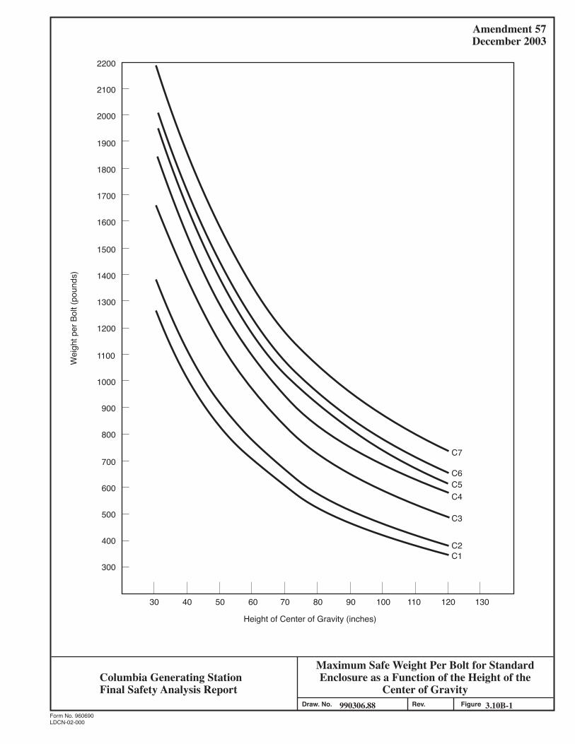
Amendment 57December 2003
Maximum Safe Weight Per Bolt for StandardEnclosure as a Function of the Height of the
Center of Gravity990306.88 3.10B-1Figure
Form No. 960690
Draw. No. Rev.
Height of Center of Gravity (inches)
Wei
ght p
er B
olt (
poun
ds)
C7
C6C5
C1C2
C3
C4
30 40 50 60 70 80 90 100 110 120 130
2200
2100
2000
1900
1800
1700
1600
1500
1400
1300
1200
1100
1000
900
800
700
600
500
400
300
Columbia Generating StationFinal Safety Analysis Report
LDCN-02-000

COLUMBIA GENERATING STATION Amendment 57 FINAL SAFETY ANALYSIS REPORT December 2003
LDCN-02-000 3.10C-1
Appendix 3.10C SAMPLE PANEL FREQUENCY ANALYSIS FOR NUCLEAR STEAM SUPPLY SYSTEM EQUIPMENT TABLE OF CONTENTS 3.10C.1 METHOD OF ANALYSIS ................................................ 3.10C-3 3.10C.2 FIRST APPROXIMATION ............................................... 3.10C-3 3.10C.3 SECOND APPROXIMATION ........................................... 3.10C-4 3.10C.4 DEFLECTION ............................................................. 3.10C-4 3.10C.5 ASSESSMENT OF CONSERVATIVENESS............................ 3.10C-4

COLUMBIA GENERATING STATION Amendment 53 FINAL SAFETY ANALYSIS REPORT November 1998
3.10C-2
Appendix 3.10C SAMPLE PANEL FREQUENCY ANALYSIS FOR NUCLEAR STEAM SUPPLY SYSTEM EQUIPMENT LIST OF FIGURES Number Title 3.10C-1 Corner Post 3.10C-2 Plan View of Panel 3.10C-3 Barrier With Two End Plates 3.10C-4 Panel Deflections 3.10C-5 Top Frame Deflection

COLUMBIA GENERATING STATION Amendment 53 FINAL SAFETY ANALYSIS REPORT November 1998
3.10C-3
Appendix 3.10C SAMPLE PANEL FREQUENCY ANALYSIS FOR NUCLEAR STEAM SUPPLY SYSTEM EQUIPMENT 3.10C.1 METHOD OF ANALYSIS The method of analysis used to determine the resonant frequency of the panel is as follows:
a. Calculate the moment of inertia of the corner post structure. b. First assume a simplified structure and calculate the frequency using the
expression:
( )( )f Kg w g k w w k
f
= = =
=
1 2 2 313
313
/ / / / . /
.
π π
σ where f = frequency, Hz g = 386 in./sec2 k = spring rate lbs/in. w = weight lbs σ = deflection = w/k = in.
weight distribution is assumed to be uniform.
c. Additional structural components are added and the moment and frequency
recalculated. The calculated resonant frequency of 7.4 Hz for the panel and 5.9 Hz for the benchboard was obtained using only the corner posts and the top. The addition of skin (3/8-in. steel) and 2-in. x 1/4-in. steel stiffeners will raise the frequency further. This proves that resonances cannot exist in the unstable region below 5 Hz. 3.10C.2 FIRST APPROXIMATION For first approximation lump the four corner posts together and assume the panel is a cantilever beam fixed on one end and uniformly loaded (see Figure 3.10C-1).
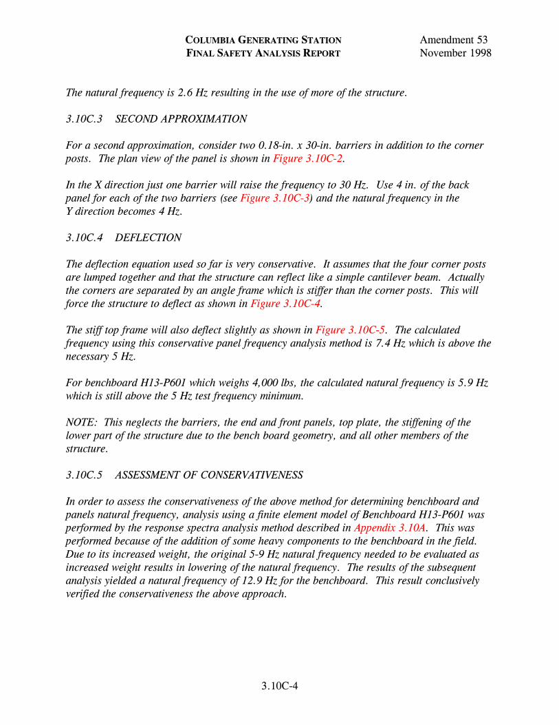
COLUMBIA GENERATING STATION Amendment 53 FINAL SAFETY ANALYSIS REPORT November 1998
3.10C-4
The natural frequency is 2.6 Hz resulting in the use of more of the structure. 3.10C.3 SECOND APPROXIMATION For a second approximation, consider two 0.18-in. x 30-in. barriers in addition to the corner posts. The plan view of the panel is shown in Figure 3.10C-2. In the X direction just one barrier will raise the frequency to 30 Hz. Use 4 in. of the back panel for each of the two barriers (see Figure 3.10C-3) and the natural frequency in the Y direction becomes 4 Hz. 3.10C.4 DEFLECTION The deflection equation used so far is very conservative. It assumes that the four corner posts are lumped together and that the structure can reflect like a simple cantilever beam. Actually the corners are separated by an angle frame which is stiffer than the corner posts. This will force the structure to deflect as shown in Figure 3.10C-4. The stiff top frame will also deflect slightly as shown in Figure 3.10C-5. The calculated frequency using this conservative panel frequency analysis method is 7.4 Hz which is above the necessary 5 Hz. For benchboard H13-P601 which weighs 4,000 lbs, the calculated natural frequency is 5.9 Hz which is still above the 5 Hz test frequency minimum. NOTE: This neglects the barriers, the end and front panels, top plate, the stiffening of the lower part of the structure due to the bench board geometry, and all other members of the structure. 3.10C.5 ASSESSMENT OF CONSERVATIVENESS In order to assess the conservativeness of the above method for determining benchboard and panels natural frequency, analysis using a finite element model of Benchboard H13-P601 was performed by the response spectra analysis method described in Appendix 3.10A. This was performed because of the addition of some heavy components to the benchboard in the field. Due to its increased weight, the original 5-9 Hz natural frequency needed to be evaluated as increased weight results in lowering of the natural frequency. The results of the subsequent analysis yielded a natural frequency of 12.9 Hz for the benchboard. This result conclusively verified the conservativeness the above approach.

Amendment 55May 2001
Corner Post
990306.89 3.10C-1FigureForm No. 960690
Draw. No. Rev.
XX
1/2"
3 in.
1 in.
3 in.
0.18 in.
Weight 2500 lbs.Panel No 730EB11
Columbia Generating StationFinal Safety Analysis Report

Amendment 55May 2001
Plan View of Panel
990306.90 3.10C-2FigureForm No. 960690
Draw. No. Rev.
4 in. 4 in.
Y
XX
X
Columbia Generating StationFinal Safety Analysis Report

Amendment 55May 2001
Barrier with Two End Plates
990306.91 3.10C-3FigureForm No. 960690
Draw. No. Rev.
Actually a Full Plate
4 in. 1 2 3
4
X X
Columbia Generating StationFinal Safety Analysis Report

Amendment 55May 2001
Panel Deflections
990306.92 3.10C-4FigureForm No. 960690
Draw. No. Rev.
δ δ
Simple CantileverBeam
SimulatedModel
δ2
InflectionPoint
Frame
Columbia Generating StationFinal Safety Analysis Report

Amendment 55May 2001
Top Frame Deflection
990306.93 3.10C-5FigureForm No. 960690
Draw. No. Rev.
3 x 2 x χ
Columbia Generating StationFinal Safety Analysis Report

COLUMBIA GENERATING STATION Amendment 53 FINAL SAFETY ANALYSIS REPORT November 1998
3.11-1
3.11 ENVIRONMENTAL DESIGN OF MECHANICAL AND ELECTRICAL EQUIPMENT This section provides information on the environmental conditions and design bases for which the instrumentation and electrical portions of the engineered safety features (ESF) and reactor protection systems (RPS) have been designed and qualification documentation generated to ensure acceptable performance in all environments in which the equipment is or to which it may be potentially exposed. The design bases for equipment qualification for CGS safety-related equipment is IEEE 323, 1971. This standard was selected as the design basis for qualification requirements contained in specifications and equipment purchase orders. Equipment suppliers were required to provide certification that supplied equipment meets the requirements of IEEE 323, 1971, for equipment intended for installation in potentially harsh environment areas of CGS. Subsequent to NRC acceptance of this design basis at the construction permit stage, the NRC required evaluation of the equipment’s environmental qualification to NUREG-0588 Category II. The NRC also required that equipment whose qualification documentation does not meet the requirements set forth in NUREG-0588 Category II be re-qualified or justification provided as to why the existing documentation is sufficient. Subsequent to the issuance of NUREG-0588 the NRC amended 10 CFR Part 50.49. This expanded the scope of equipment to be considered for electrical equipment qualification and required that replacement of electrical equipment be qualified to the provisions of 10 CFR Part 50.49 unless sound reasons to the contrary are provided. The CFR also instituted a requirement to provide an analysis as to why the plant can be operated safely, pending completion of any requalification or equipment replacement action that could not be accomplished prior to operation of CGS. The CGS Equipment Qualification Program includes two major subprograms. They are the CGS Dynamic Qualification Program and the CGS Environmental Qualification Program. The CGS Environmental Qualification Program, discussed within this section, is designed to ensure that electrical equipment important to safety is qualified to the provisions of NUREG-0588 Category II and applicable provisions of 10 CFR Part 50.49. Details of the initial CGS environmental qualification program are provided in Reference 3.11-1. The following summarizes the current CGS environmental qualification program.

COLUMBIA GENERATING STATION Amendment 53 FINAL SAFETY ANALYSIS REPORT November 1998
3.11-2
3.11.1 EQUIPMENT IDENTIFICATION AND ENVIRONMENTAL CONDITIONS 3.11.1.1 Identification of Electrical Equipment Important to Safety The criteria for identification of electrical equipment important to safety are defined in Section 3.11.1.1.1 through 3.11.1.1.4. The electrical equipment defined in these sections is included in the Master Equipment List (MEL). Electrical equipment in these sections may experience the conditions of design basis accidents due to their plant location. In addition, the cumulative gamma radiation dose to equipment in these areas is, in general, above 1 x 10⁴ rad. This equipment is located in the primary and secondary containment areas of the CGS reactor building. Safety-related equipment outside the reactor building and in some reactor building electrical equipment rooms is not exposed to a significant change from the normal service environment or anticipated operating occurrences as a result of design basis accidents and therefore are not a part of the environmental qualification program. In addition, the cumulative gamma radiation dose to equipment in these areas is generally below 1 x 10⁴ rad. Also excluded from the environmental qualification program is safety-related electrical equipment that will experience environmental conditions of design basis accidents through which it need not function for mitigation of such accidents; or that has performed its safety function prior to the exposure to an accident environment; and whose failure (in any mode) is deemed not detrimental to plant safety or accident mitigation and will not mislead the operator. This equipment has been identified and included in the CGS dynamic qualification program described in Section 3.10. Electrical equipment important to safety that only performs a mechanical safety function, such as the maintenance of mechanical pressure integrity, and whose electrical failure (in any mode) or change of state is of no safety significance, is considered to be similar to mechanical devices and is not addressed by the CGS environmental qualification program. The following equipment specific data was determined for electrical equipment important to safety and is included in either the MEL or Passport databases:
a. Equipment piece number (i.e., unique plant tag number), b. Manufacturer, c. Model number or manufacturer’s identification reference, d. Active or passive classification,

COLUMBIA GENERATING STATION Amendment 54 FINAL SAFETY ANALYSIS REPORT April 2000
LDCN-99-000 3.11-3
e. Equipment use classification per the equipment categories defined in Appendix E of Regulatory Guide 1.89, Revision 1,
f. System/component level safety function(s), g. Equipment plant location, and h. Equipment period of operability during accident condition.
3.11.1.1.1 Engineered Safety Features and Reactor Protection System Equipment An ESF is a safety-related system that provides a safety function to mitigate the consequences of a design basis accident that may cause major fuel damage. An ESF includes the primary auxiliary systems of the safety system. The identification, location, and accident environmental design bases for these safety-related systems and/or components are provided in the MEL, calculations, and supporting documents. This equipment includes safety-related electrical equipment (Class 1E) that is relied on to remain functional during and following accident exposure by loss-of-coolant accidents (LOCA), main steam line break (MSLB) accidents, high-energy line break (HELB) accidents, and rod drop accidents. The electrical equipment included in the program is that equipment necessary to ensure the
a. Integrity of the reactor coolant pressure boundary, b. Capability to shut down the reactor and maintain it in a safe shutdown condition,
or c. Capability to prevent or mitigate the consequences of the above accidents that
could result in potential offsite exposures comparable to the 10 CFR Part 100 guidelines.
3.11.1.1.2 Postaccident Monitoring Electrical Equipment In addition to Class 1E equipment identified in Section 3.11.1.1.1, electrical and instrumentation equipment identified by Regulatory Guide 1.97, Revision 2 (Category I and II), and NUREG-0737 are included in the environmental qualification program. Instruments meet the requirements by category and type as described in Regulatory Guide 1.97, Revision 2, unless noted in text discussions as meeting Regulatory Guide 1.97, Revision 3, requirements (see Section 7.5.2.2.3). 3.11.1.1.3 Other Electrical Equipment Important to Safety Included in the environmental qualification program is equipment that is not classified as safety-related (Class 1E). This equipment may experience the environmental conditions of

COLUMBIA GENERATING STATION Amendment 53 FINAL SAFETY ANALYSIS REPORT November 1998
3.11-4
design basis accidents and the results of failure of this equipment due to the design basis accidents may prevent satisfactory accomplishment of the safety function of safety-related equipment. Qualification requirements for electrical equipment required to mitigate anticipated transients without scram (ATWS) or used for remote shutdown are provided in Section 1.5.1.1.2, 7.1.2.4, and 7.4.2.3. 3.11.1.1.4 Electrical Equipment Whose Failure Does Not Affect Safety Function
Performance In the development of the list of electrical equipment important to safety, electrical equipment was identified that may be exposed to environments created by design basis accidents whose failure during or following the accident exposure would have no affect on safety function performance. Failure modes and effect evaluations were performed to justify their removal from the environmental qualification program. 3.11.1.1.5 Safety-Related Mechanical Equipment Safety-related mechanical equipment is not included in the environmental qualification program. This includes ATWS equipment with only a mechanical augmented quality function. The design verification requirements cited in Reference 3.11-2 are met outside the environmental qualification program. 3.11.1.1.6 Identification of Safety-Related Equipment In Mild Environmental Plant Areas Safety-related electrical equipment located in areas of the plant that are not exposed to significant environmental effects resulting from design basis accidents are considered mild environments and are also identified within the CGS equipment qualification program. Equipment in ESF and RPS located in mild environments will not experience a significant change in its environmental conditions and, therefore, need only be qualified to the service conditions resulting from seismic design basis events. This also includes equipment that may be exposed to a total integrated radiation dose (normal plant operations including anticipated operational occurrences + accident) in excess of 1 x 10⁴ rad if the accident radiation does not significantly exceed the 40-year integrated radiation dose due to normal plant operations and anticipated operational occurrences. Safety-related equipment located in a mild environment where the total integrated radiation dose exceeds 1 x 10⁴ rad, or exceeds 1 x 10³ rad for equipment containing certain classes or categories of solid state electronics as defined within qualification program procedures and supporting documents, have been specifically excluded from the environmental qualification program. However, this equipment is either procured to the required radiation dose provided in the procurement specifications or is evaluated for acceptable operability due to radiation exposure effects only, in its service environment. The identification of this equipment is provided in the MEL. See Section 3.10 for additional details.

COLUMBIA GENERATING STATION Amendment 53 FINAL SAFETY ANALYSIS REPORT November 1998
3.11-5
3.11.1.2 Normal and Accident Environmental Service Conditions The normal and accident environmental service conditions have been defined for electrical equipment important to safety and are identified in this section. The environmental parameters include temperature, pressure, relative humidity, demineralized water spray, submergence, and radiation. 3.11.1.2.1 Normal Plant Operational Environmental Conditions (Except Radiation) Plant operational environmental conditions are without significant abnormalities and include the following: planned startups, power range, shutdown, and normal hot standby. These environmental conditions, specified for the various buildings and/or areas, are listed in Table 3.11-1 and represent normal temperatures and maximum and minimum design bases for temperature, relative humidity, and pressure to which equipment may be exposed during routine plant operations and short-term abnormal conditions due to anticipated operating occurrences. See Figure 3.11-1 for primary containment zone locations. 3.11.1.2.2 Accident Environmental Service Conditions (Except Radiation) The primary containment and most areas of the secondary containment within the reactor building potentially could be exposed to elevated temperature, pressure, and high humidity conditions resulting from LOCA, MSLB, or HELB type accidents. Pressure and temperature profiles were defined for two accident types: LOCA/MSLB in primary containment and HELBs in the secondary containment of the reactor building. Break locations were determined (see Section 3.6), and equipment required to operate during or following exposure to the environmental conditions resulting from the breaks identified. The CGS plant-specific pressure/temperature profiles of the primary containment and the equipment required to operate during or following the postulated breaks are provided in the MEL, LOCA and MSLB analysis calculations, and supporting documents. Table 3.11-2 provides generic environmental conditions obtained from a GE analysis of the response of a BWR Mark II containment to a full spectrum of possible LOCA and MSLB. These generic environmental conditions were used for equipment qualification evaluations of equipment in primary containment. Plant-specific profiles are used for the postaccident period as required by NUREG-0588. In addition to pressure/temperature and humidity conditions inside primary containment, demineralized spray and potential flooding was included in the definition of the environmental service conditions. Plant-specific pressure/temperature and humidity profiles were also defined for equipment spaces within the secondary containment areas of the reactor building. General Electric generic conditions were not used. These profiles are provided in HELB analysis calculations and

COLUMBIA GENERATING STATION Amendment 53 FINAL SAFETY ANALYSIS REPORT November 1998
3.11-6
supporting documents. In addition to pressure/temperature and humidity, the affect of flooding was evaluated. The results of the flooding analysis determined that CGS can be safely shut down with alternative safety-related equipment not affected by flooding. Based on this, flooding is not a required environmental service condition for equipment qualification in the secondary containment except for the high-pressure core spray (HPCS), low-pressure core spray (LPCS), reactor core isolation cooling (RCIC), and residual heat removal (RHR) reactor building pump rooms. 3.11.1.2.3 Radiation Service Conditions The primary containment radiation conditions determined for environmental qualification include the normal (40-year dose) and the accident radiation dose (180 days). The criteria for determining the radiation dose were NUREG-0737 and NUREG-0588. The calculated radiation environment is based on normal service conditions, plus the most severe nonmechanistic design basis accident during or following which equipment must function. Required period of operability for the equipment was a factor used to determine equipment specific radiation dose. The accidents considered are the entire spectrum of Chapter 15 accidents that can lead to a degraded core condition. The source term assumptions for postulated accidents are consistent with those defined in NUREG-0588 and Regulatory Guides 1.3 and 1.7. The secondary containment radiation conditions are defined according to Section II.B.2 of NUREG-0737 and NUREG-0588. The total integrated dose includes the sum of direct accident gamma dose, airborne gamma dose, 40-year normal gamma dose, and where equipment could be beta sensitive, a beta dose. This beta dose was determined through use of energy dependent geometry factors, a ratio of the internal equipment volume to an infinite cloud, and the dose to a target at the center point face for a hemispherical cloud of gases. The dose and dose rate were determined for equipment areas within the secondary containment. The secondary containment was divided into radiation zones to define the equipment radiation service conditions. The worst target (component with the highest dose) in each zone was chosen. This radiation value was then used as a screening value for all equipment in the zone. In some zones, additional targets were chosen to more realistically map the radiation conditions throughout some zones. The methodology and results of the radiation evaluations are provided in CGS radiation dose calculations. The results of evaluations for specific equipment to radiation conditions are contained in the CGS Qualification Information Documents (QIDs). 3.11.1.2.4 Accident Conditions - Harsh Environments The primary containment and most areas of the reactor building will be exposed to a harsh environment following a postulated LOCA/HELB. A harsh environment is defined as

COLUMBIA GENERATING STATION Amendment 54 FINAL SAFETY ANALYSIS REPORT April 2000
LDCN-99-000 3.11-7
An area that would be exposed to a significant increase in the maximum temperature, pressure, and humidity as a direct result of design basis events and/or the total radiation dose (normal + accident) is above 1 x 10⁴ rad, or above 1 x 10³ rad for certain classes or categories of solid state electronics, with a significant increase in radiation dose during accident conditions compared to that during normal plant operations, including anticipated operational occurrences.
3.11.2 QUALIFICATION TESTS AND ANALYSES In accordance with NUREG-0588 Category II requirements, descriptions of the qualification tests and analyses have been provided in the QIDs. These QIDs are prepared in accordance with Energy Northwest Engineering Standards. The information provided is consistent with Appendix E of NUREG-0588 and includes the methods employed to address temperature, pressure, humidity, spray, radiation, and aging. Specific values (both required and demonstrated) are provided in equipment qualification summary sheets in the QIDs. These summary reports indicate how the general requirements of General Design Criteria 1, 4, 23, and 50 of Appendix A to 10 CFR Part 50, and 10 CFR Part 50.49 are met. The CGS equipment qualification program meets Criterion III of Appendix B to 10 CFR Part 50 through implementation of Quality Class 1 procedures for all aspects of the evaluation, documentation, and corrective action resulting from the program. Section 1.8 addresses how Regulatory Guides 1.30, 1.40, 1.63, 1.73, and 1.89 were applied to the CGS qualification program. 3.11.3 QUALIFICATION PROGRAM RESULTS The results of qualification test and analysis for each piece of equipment in the CGS Environmental Qualification Program is provided in the QIDs. A typical Equipment Qualification Report Summary from a QID is shown in Figure 3.11-2. 3.11.3.1 NRC Review of the CGS Environmental Qualification Program The NRC staff evaluation of the CGS Environmental Qualification Program included an examination of the installed electrical equipment and audits of both electrical and mechanical equipment qualification documentation. A review of Energy Northwest’s submittals for completeness and acceptability of systems and components, qualification methods, and accident environments was also conducted. The criteria described in Standard Review Plan Section 3.11 (NUREG-0800) and NUREG-0588, Category II, formed the basis for the NRC’s evaluation of the adequacy of the CGS program.

COLUMBIA GENERATING STATION Amendment 54 FINAL SAFETY ANALYSIS REPORT April 2000
LDCN-99-000 3.11-8
An audit was performed of the CGS qualification documentation and installed equipment in February 1983 and was documented by the NRC in NUREG-0892, Supplement 3. A subsequent audit was made to assess implementation of the concerns and resolutions raised in the February 1983 audit. These files were found acceptable by the NRC as reported in Supplements 4 and 5 of NUREG-0892, Reference 3.11-2. Mechanical equipment is no longer a part of the environmental qualification program and is addressed separately (see Section 3.11.1.1.5). 3.11.3.2 Establishment of Operational Phase Environmental Qualification Review Energy Northwest has established an operational phase environmental qualification review. This review is integrated with design changes to CGS to ensure compliance with the criteria as described in Section 3.11. The operational phase qualification review is required for all design changes that add, modify, or delete safety-related equipment for CGS because of plant betterment, regulatory, or license conditions requirements. Design control procedures establish a special qualification review as part of the design change package preparation. Adequacy of the equipment selected to be added to the plant in the design change is assessed and documented to an “As Designed” qualification status. Special procurement requirements are detailed for the purchase order. During or after installation, quality control inspections are conducted to ensure final installation conforms to design documents and final qualification documentation is established in QID files. A walkdown is performed by equipment qualification personnel if needed to clarify the final installation configuration. For design changes that modify or reclassify existing plant equipment, a special review is also required similar to the above. Final documentation is established in QID files on completion of the design change. For design changes that delete existing plant equipment or change its status to non-safety-related, a special review is also conducted. In these instances, modification of the QID file is considered optional under the program. Design control procedures also require the safety-related equipment list in the MEL is to be kept current with actual plant configuration. Thus, consonance of the plant equipment configuration and qualification documentation (QID files) is maintained throughout plant life.

COLUMBIA GENERATING STATION Amendment 60 FINAL SAFETY ANALYSIS REPORT December 2009
LDCN-09-011 3.11-9
Plant modifications to environmental control systems that alter environmental profiles to which equipment has previously been qualified are reviewed to ensure equipment is qualified to revised profiles. The NRC Bulletins and Information Notices that affect qualification of plant equipment are reviewed and factored into the qualification review. Design changes that result from NRC Bulletin and Information Notice reviews also receive the special qualification review. The qualification program is linked with the maintenance program to ensure that required maintenance or replacement due to qualified life considerations are performed. Refinement of the qualified life is included based on actual service conditions and actual equipment degradation evaluations through monitoring, inspection, and surveillance programs. Replacement equipment is qualified in accordance with Regulatory Guide 1.89, Revision 1. Where necessary, engineering evaluations are performed using the criteria and guidance for establishing sound reasons to the contrary provided in Regulatory Guide 1.89, Revision 1, and Generic Letter 82-09, as applicable. 3.11.4 LOSS OF VENTILATION 3.11.4.1 Main Control Room Air Conditioning and Ventilation System Controls and electrical equipment necessary for safe plant shutdown are located in the main control room. The control room is air conditioned and shielded against radiation to allow the operators safe and continued occupancy under optimum environmental conditions. Air conditioning equipment and associated components are designed to Seismic Category I requirements. Redundant equipment is provided and on loss of offsite power, emergency power from the onsite diesel generator sets is automatically supplied to the equipment. No single failure can result in loss of control room air conditioning. Hence, design of the system ensures that the operability of the safety-related control and electrical equipment located in the control room will not be impaired and will continue to function in an acceptable environment. Therefore, no special environmental design requirements for loss of ventilation or air conditioning need be incorporated in the design of safety-related electrical or instrumentation equipment located in the control room. 3.11.4.2 Reactor Building Emergency Cooling System Some equipment located within the reactor building which must operate in the event of an accident could not survive direct exposure to the accident environment. This equipment is located in enclosed electrical equipment rooms. In the event of an accident, these rooms are automatically isolated from the normal reactor building ventilation system and subsequently are maintained at the required environmental conditions by the reactor building emergency cooling system (see Section 9.4.9).

COLUMBIA GENERATING STATION Amendment 60 FINAL SAFETY ANALYSIS REPORT December 2009
3.11-10
The reactor building emergency cooling system consists of independent air recirculation systems each of which is fully enclosed within the room it serves and is designed to Seismic Category I standards. The air recirculation system for a room is powered from the same emergency diesel generator bus as the equipment in the room. Since each air recirculation system is independent and serves redundant emergency equipment systems, a failure of one air recirculation system does not affect the operation of other air recirculation systems or the safe shutdown of the reactor. 3.11.4.3 Miscellaneous Ventilation Systems Each of the following areas are serviced by at least one ESF heating, ventilating, and air conditioning (HVAC) system:
b. Critical switchgear area, radwaste building (Section 9.4.1), c. Emergency diesel generator building (Section 9.4.7), d. Critical electrical cable runs, between the diesel generator building and the
radwaste building (Section 9.4.8), and e. Standby service water pump houses (Section 9.4.10).
Ventilation failures in these areas are considered and evaluated in Section 9.4. During some design basis events, short periods of elevated service water temperature may affect the normal temperatures of some mild environment rooms (see Section 9.4 and Table 3.11-1). No significant thermal aging will result from the temperature excursions. Design reviews were conducted to ensure that the resulting operating conditions will not cause safety-related equipment located in these areas to fail. 3.11.5 ESTIMATED CHEMICAL AND RADIATION ENVIRONMENT 3.11.5.1 Suppression Pool, Residual Heat Removal System, and Emergency Core Cooling
System Water Quality The water in these systems is not chemically inhibited. The maximum limits for the suppression pool for normal operation have been established to be compatible with those of the primary coolant and are listed in Table 3.11-3 for comparison. The fuel pool cooling and cleanup system has provisions for circulating the suppression pool water through demineralizers to maintain water quality limits.

COLUMBIA GENERATING STATION Amendment 53 FINAL SAFETY ANALYSIS REPORT November 1998
3.11-11
During reactor shutdown cooling, the RHR system water mixes with reactor water. Therefore, to ensure reactor water quality, the shutdown cooling piping and equipment is flushed with water of the quality specified in Table 3.11-3 for maximum limit with suspended solids concentration of 5 ppm or less. During layup the RHR system will be filled with water which meets the limits specified in Table 3.11-3. 3.11.5.2 Qualification Qualification of equipment for severe chemical exposure is considered unnecessary since no sources of detrimentally high or low pH have been identified for the postulated post-LOCA conditions. The post-LOCA water qualities would be expected to be similar to that shown in Table 3.11-3 (see Section 6.1.3). Radiation environment conditions and equipment qualifications are discussed in Section 3.11.1.2.3 and 3.11.2 respectively. 3.11.6 REFERENCES 3.11-1 WNP-2 Environmental Qualification Report for Safety-Related Equipment,
dated September 1983 (historical document). 3.11-2 Safety Evaluation Report Related to the Operation of WPPSS Nuclear Project
No. 2, NUREG-0892, Supplement 3 (May 1983), Supplement 4 (December 1983), and Supplement 5 (April 1984).

Table 3.11-1
Normal Operating Conditions
Area
Pressure (as noted)
Temperature (F)
Relative Humidity (%)
C
OL
UM
BIA
GE
NE
RA
TIN
G S
TA
TIO
N A
mendm
ent 61
FIN
AL
SA
FE
TY
AN
AL
YSIS R
EP
OR
TD
ecember 2011
LD
CN
-09-039 3.11-13
I. Primary containment (not otherwise noted) 0.25 to 0.75 psig (nominal)m 135 bulk average maximuma 70 minimum 150 maximum
40-55 normalNA - minimum 100 maximum
Vicinity recirculation pump motors zone 4b
0.25 to 0.75 psig (nominal)m 70 minimumc 135 maximum
40-55 normal NA - minimum 100 maximum
Area beneath RPV zone 3b
0.25 to 0.75 psig (nominal)m 70/100 minimum averaged 165 maximum
40-55 normal NA - minimum 100 maximum
Sacrifical shield wall lower/mid annulus 0.25 to 0.75 psig (nominal)m 70/100 minimum averaged 185 maximum/150 average
40-55 normal NA - minimum 100 maximum
Suppression pool air volume zone 6b
0.25 to 0.75 psig (nominal)m 50 minimum 150 maximum 117 (operating limit)
40-55 normal NA - minimum 100 maximum
Suppression pool water volume
50 minimum Maximum - See Technical Specification 3.6.2.1
II. Reactor building (not otherwise noted) Nominal -0.6 in. water gauge, static pressure (unless otherwise noted)
70-90 normal 40/50 minimuml 104 maximumh
40 normal 20 minimum 90 maximum
RCIC equipment area 70-90 normal 60 minimum 104 maximum equip not running150 maximum equip running
40 normal 20 minimum 90 maximum (e)

Table 3.11-1
Normal Operating Conditions (Continued)
Area
Pressure (as noted)
Temperature (F)
Relative Humidity (%)
C
OL
UM
BIA
GE
NE
RA
TIN
G S
TA
TIO
N A
mendm
ent 61
FIN
AL
SA
FE
TY
AN
AL
YSIS R
EP
OR
TD
ecember 2011
3.11-14
HPCS, LPCS and RHR equipment area 70-90 normal 40 minimum 104 maximum equip not running150 maximum equip running
40 normal 20 minimum 90 maximum (e)
II. Reactor building (Continued)
Steam tunnel 130 normali 40 minimum 140 maximum
40-50 normal 20 minimum 98 maximum
RWCU piping and pump area (R406, R407, R409)
118 maximum 40-50 normal 20 minimum 98 maximum
Pipe space south (R405) 109 maximum 40-50 normal 20 minimum 98 maximum
Shielded pipe space south (R511) 111 maximum 40-50 normal 20 minimum 98 maximum
New fuel storage vault 116 maximum 40-50 normal 20 minimum 98 maximum
Refueling floor 40/64 minimumj 40-50 normal 20 minimum 98 maximum
III. Turbine building 0.0 in. to -0.25 in. water gauge, static pressure
70-90 normal 40 minimum (non-elec) 50 minimum (elec) 104 maximum (elec) 120 maximum (non-elec)
40 normal 20 minimum 90 maximum

Table 3.11-1
Normal Operating Conditions (Continued)
Area
Pressure (as noted)
Temperature (F)
Relative Humidity (%)
C
OL
UM
BIA
GE
NE
RA
TIN
G S
TA
TIO
N A
mendm
ent 61
FIN
AL
SA
FE
TY
AN
AL
YSIS R
EP
OR
TD
ecember 2011
3.11-15
Area above main steam lines 200 maximum 40 normal20 minimum 90 maximum
IV. Radwaste building 0.0 in. to -0.25 in. water gauge, static pressure
70 normalf 40/55/60 minimumg 104 maximumh
50 normal90 maximum 20 minimum
Radwaste building equipment cells 0.0 in. to -0.5 water gauge, static pressure
70 normal 40 minimum 120 maximum
40 normal 20 minimum 90 maximum
V. Control room 0.10 in. to 1.0 in. water gauge, static pressure
72-78 normal40 minimum 85/104 maximumk
40-50 normal60 maximum 10 minimum
VI. Critical switchgear rooms 0.0 in. to -0.25 in. water gauge, static pressure
70 normal 55 minimum 104 maximum (elec)h
40 normal 20 minimum 90 maximum
VII. Diesel generator building Ambient 60-95 normaln 60 normal 10 minimum 90 maximum
Emergency diesel generator engine rooms 40 minimum 120 maximum
HPCS diesel generator engine room 40 minimum 112 maximum
Emergency diesel generator electrical switchgear rooms
50 minimum 104 maximum

Table 3.11-1
Normal Operating Conditions (Continued)
Area
Pressure (as noted)
Temperature (F)
Relative Humidity (%)
C
OL
UM
BIA
GE
NE
RA
TIN
G S
TA
TIO
N A
mendm
ent 62
FIN
AL
SA
FE
TY
AN
AL
YSIS R
EP
OR
T D
ecember 2013
LD
CN
-11-007 3.11-16
HPCS diesel generator electrical switchgear/ battery room
60 minimum 104 maximum
Cable Corridor 40 minimum 104 maximum
VIII. Service water pump building 0.0 in. to +0.25 in. water gauge, static pressure
50-104 normal 40 minimum 114 maximum (elec)h
60 normal 10 minimum 90 maximum
a Average or bulk temperature. See Technical Specification 3.6.1.4.
b See Figure 3.11-1 for zone locations. c Minimum temperature for operational and maintenance for RRC pump loop piping general bolting materials specifications.
d The same minimum normal average operational temperature (100F) shall apply at the inside base of the sacrificial shield wall. Air velocity over vessel insulation and exposed vessel parts shall be approximately 6 ft/sec. 70F average applies when not in mode 1, or mode 2 or 3 with RPV piping >275 psig and 200F.
e The maximum temperature and humidity will occur simultaneously in these spaces less than 1% of the time.
f Normal for cable spreading room is 80F.
g Minimum for critical switchgear area is 55F (60F in battery rooms). LCS 1.7.1 lists minimum normal for battery rooms as 74°F to support Station Black Out (SBO) commitment.
h During design basis events this temperature may be exceeded for a short period of time (<30 days). These room temperatures are used to support the evaluated design capability of equipment during design basis events. Analysis has confirmed that equipment with a design safety function is capable of operating at the temperature listed below.
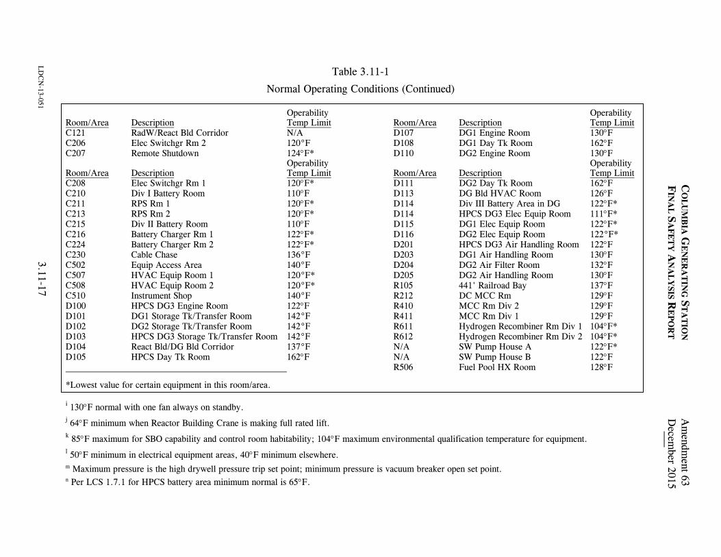
Table 3.11-1
Normal Operating Conditions (Continued)
LD
CN
-13-051 3.11-17
C
OL
UM
BIA
GE
NE
RA
TIN
G S
TA
TIO
N A
mendm
ent 63
FIN
AL
SA
FE
TY
AN
AL
YSIS R
EP
OR
T D
ecember 2015
Operability Operability Room/Area Description Temp Limit Room/Area Description Temp Limit C121 RadW/React Bld Corridor N/A D107 DG1 Engine Room 130F C206 Elec Switchgr Rm 2 120°F D108 DG1 Day Tk Room 162F C207 Remote Shutdown 124F* D110 DG2 Engine Room 130F Operability Operability Room/Area Description Temp Limit Room/Area Description Temp Limit C208 Elec Switchgr Rm 1 120F* D111 DG2 Day Tk Room 162F C210 Div I Battery Room 110F D113 DG Bld HVAC Room 126F C211 RPS Rm 1 120F* D114 Div III Battery Area in DG 122F* C213 RPS Rm 2 120F* D114 HPCS DG3 Elec Equip Room 111F* C215 Div II Battery Room 110F D115 DG1 Elec Equip Room 122F* C216 Battery Charger Rm 1 122F* D116 DG2 Elec Equip Room 122°F* C224 Battery Charger Rm 2 122F* D201 HPCS DG3 Air Handling Room 122F C230 Cable Chase 136°F D203 DG1 Air Handling Room 130F C502 Equip Access Area 140°F D204 DG2 Air Filter Room 132F C507 HVAC Equip Room 1 120°F* D205 DG2 Air Handling Room 130F C508 HVAC Equip Room 2 120°F* R105 441' Railroad Bay 137F C510 Instrument Shop 140°F R212 DC MCC Rm 129F D100 HPCS DG3 Engine Room 122F R410 MCC Rm Div 2 129F D101 DG1 Storage Tk/Transfer Room 142°F R411 MCC Rm Div 1 129F D102 DG2 Storage Tk/Transfer Room 142°F R611 Hydrogen Recombiner Rm Div 1 104F* D103 HPCS DG3 Storage Tk/Transfer Room 142°F R612 Hydrogen Recombiner Rm Div 2 104F* D104 React Bld/DG Bld Corridor 137°F N/A SW Pump House A 122F* D105 HPCS Day Tk Room 162F N/A SW Pump House B 122F R506 Fuel Pool HX Room 128F *Lowest value for certain equipment in this room/area. i 130F normal with one fan always on standby. j 64F minimum when Reactor Building Crane is making full rated lift. k 85F maximum for SBO capability and control room habitability; 104F maximum environmental qualification temperature for equipment. l 50F minimum in electrical equipment areas, 40F minimum elsewhere. m Maximum pressure is the high drywell pressure trip set point; minimum pressure is vacuum breaker open set point. n Per LCS 1.7.1 for HPCS battery area minimum normal is 65F.

Table 3.11-2
Accident Environment Conditions (Primary Containment) for Essential Equipment
Condition
Componenta
Temperature (°F)
Pressure (psig)
Relative Humidity
Durationb
CO
LU
MB
IA G
EN
ER
AT
ING
ST
AT
ION
Am
endment55
FIN
AL
SA
FE
TY
AN
AL
YSIS R
EP
OR
TM
ay 2001
3.11-18
1 Core spray injection check valves, LPCI-RHR injection check valves, reactor shutdown cooling suction valve, safety/relief valves,c vessel level indicators, structural components (e.g., loop restraints, vessel skirt, etc.)
340 320 250 200d
-2 to 45 -2 to 45 0 to 25 0 to 20
All steam All steam 100% 100%
3 hr 6 hr 1 day 180 days
Control instrumentation air (including accumulators), reactor building closed cooling (RCC) valves,e drywell unit coolerse
2 Feedwater check valves, RCIC steam line isolation valve, reactor water cleanup suction valve, reactor water sample line valve, 2 in. and smaller isolation valves, cables to intermediate range and power range monitors, reactor vessel head spray isolation valve
340f 320
-2 to 45 -2 to 45
All steam All steam
3 hr 6 hr
3 Main steam isolation valves, main steam drain isolation valves
340 -2 to 45 All steam 1 hr
4 Recirculation gate valves,e reactor protection system neutron monitoring system
340 320
-2 to 45 -2 to 45
All steam All steam
3 hr 4.5 hr
5 Feedwater check valves, RCIC steam line isolation valve, recirculation flow control valves, reactor vessel head spray isolation valve, reactor water cleanup suction, reactor water sample line valve, 2 in. and smaller isolation valves
250 200d
-2 to 25 -2 to 20
100% 100%
1 day 180 days

Table 3.11-2
Accident Environment Conditions (Primary Containment) for Essential Equipment (Continued)
Condition
Componenta Temperature
(°F) Pressure (psig)
Relative Humidity
Durationb
C
OL
UM
BIA
GE
NE
RA
TIN
G S
TA
TIO
N A
mendm
ent 55
FIN
AL
SA
FE
TY
AN
AL
YSIS R
EP
OR
T
May 2001
LD
CN
-00-076 3.11-19
Drywell Side
Wetwell Side
6 Wetwell-drywell vacuum relief valves
340 320 250 200d
275 275 250 200d
-2 to 45 -2 to 45 0 to 25 0 to 20
All steam All steam 100% 100%
3 hr 6 hr 1 day 180 days
7 Main steam isolation valves, main steam drain isolation valves, standby liquid control injection check valve
340 320 250 200d
-2 to 45 -2 to 45 -2 to 25 -2 to 20
All steam All steam 100% 100%
3 hr 6 hr 1 day 180 days
a Typical components are listed. Components listed may have required operating time different than shown here. Specific hours to operate are described in
Reference 3.11-1 (historical) and currently in the Columbia Generating Station Master Equipment List or MEL. Also included are the valve operators and cabling (instrumentation and power) required for proper operation of the valves listed.
b Durations shown are termination times for conservative environmental conditions measured from the initiation of the postulated accident, i.e., Condition 1,
the 6-hr duration, is the period from 3 hr through 6 hr, the 1-day duration is the period from 6 hr through 1 day (24 hr). c The safety/relief valves are required to be operable for 2 days and to remain in whichever position the valve operator has been set to at the end of the 2 days
for the remainder of the long-term transient. Safety/relief valves used for automatic depressurization must remain operable throughout the long-term transient.
d Represent peak starting temperature of extended long-term temperature in the containment following a postulated design basis accident. e The RCC system, drywell air coolers, and the reactor recirculation system have no safety requirements during a LOCA. The specified conditions are
desirable to enable a normal shutdown cooling procedure during a steam leak. f The TIP system isolation valves are located outside of primary containment in the TIP room. Analysis has determined that maximum accident condition will
be 130°F.

Table 3.11-2
Accident Environment Conditions (Primary Containment) for Essential Equipment (Continued)
C
OL
UM
BIA
GE
NE
RA
TIN
G S
TA
TIO
N A
mendm
ent 55
FIN
AL
SA
FE
TY
AN
AL
YSIS R
EP
OR
T
May 2001
3.11-20
Basic Accident Environmental Pressures and Temperatures The following is a compilation of basic accident environmental pressures and temperatures and a description of the time durations expected. The full spectrum of simultaneous environmental possibilities is not presented in a series of curves, but rather as a description of the boundaries within which designated equipment will be qualified for discrete times during the cycles/modes of the reactor’s operation for the first 24 hr. Plant-specific temperature/ pressure profiles have been calculated to define the conservatism inherent in these generic environmental values. No margin is required when these values are met in equipment qualification test programs. Temperatures 340°F Superheat temperature for a steam leak with the reactor vessel at 400-500 psi, containment at 45 psig. 320°F Superheat temperature during shutdown cooling line flush after reactor has been depressurized to 150 psia which corresponds to the pressure at which
the shutdown cooling system is activated. 250°F Long-term temperature in the containment during the first day following a postulated design basis accident. 200°F Peak starting temperature of extended long-term temperature in the containment following a postulated design basis accident. Plant-specific
calculations have been determined per NUREG-0588. Pressures -2 psig Assumed minimum pressure of the primary containment. 45 psig Maximum positive internal pressure of the primary containment. 25 psig Pressure up to 1 day following a postulated design basis accident. 20 psig Pressure at 1 day and longer following a postulated design basis accident.

Table 3.11-2
Accident Environment Conditions (Primary Containment) for Essential Equipment (Continued)
C
OL
UM
BIA
GE
NE
RA
TIN
G S
TA
TIO
N A
mendm
ent 55
FIN
AL
SA
FE
TY
AN
AL
YSIS R
EP
OR
TM
ay 2001
3.11-21
Duration 1 hr Applies to valves that isolate automatically on low RPV pressure or level. This time interval represents a conservative duration during which the
valves must be qualified. Required operating time is 0.17 hr. 3 hr Time duration to depressurize the reactor pressure vessel at a rate not exceeding 100°F/hr, down to 150 psia. 4.5 hr Time at which shutdown cooling system flush is complete. Normal shutdown cooling necessitates closure of recirculation line valves. 6 hr Duration of time to complete vessel depressurization to near atmospheric pressure. This time includes RPV depressurization to 150 psia not
exceeding a rate of 100°F/hr, flushing of system, depressurization to near atmospheric pressure. If shutdown cooling is not available, containment sprays should be activated before 6 hr to limit temperature to less than 250°F.

COLUMBIA GENERATING STATION Amendment 55 FINAL SAFETY ANALYSIS REPORT May 2001
3.11- 22
Table 3.11-3 Water Quality Limits Parameter
System Water Conductivity Chlorides as
Cl pH
Total Suspended
Solids and/or
Insolubles
Reactor (shutdown condition, depressurized maximum)
<10 µS/cm at 25°C
<0.5 ppm 5.3 to 8.6 at 25°C
<1 ppm
Suppression pool (quality expected) (see Section 6.1.1.2)
<5 µS/cm at 25°C
<20 ppb
5.3 to 8.6 at 25°C
<5 ppm
Suppression pool (maximum)
<10 µS/cm at 25°C
<0.5 ppm 5.3 to 8.6 at 25°C
<5 ppm
RHR (layup condition, maximum and/or refueling)
<3 µS/cm at 25°C
<0.5 ppm 5.3 to 7.5 at 25°C
<1 ppm

Amendment 55May 2001
Primary Containment Zones
990306.94 3.11-1FigureForm No. 960690
Draw. No. Rev.
Zone 1
Zone 2
Zone 3
Zone 4
Zone 5
Zone 6
Columbia Generating StationFinal Safety Analysis Report

Amendment 55May 2001
Equipment Qualification Report- Reactor Building Return Air
990306.95 3.11-2FigureForm No. 960690
Draw. No. Rev.
Columbia Generating StationFinal Safety Analysis Report
Floo
d Le
vel E
lev:
Abov
e Fl
ood
Leve
l?Ye
s X
N
o___
_ (R
ef. 5
)Pr
epar
ed b
y:__
____
____
____
____
____
____
__
R
evie
wed
by:
___
____
____
____
____
____
____
____
Equi
pmen
t Des
crip
tion
Envi
ronm
ent
Para
met
erFS
ARQ
ualif
icat
ion
FSAR
Qua
l.Q
ualif
icat
ion
Met
hod
Out
stan
ding
Item
s
Non
e
Non
e
Non
e
Non
e
Non
e
Non
e
Non
e
Non
e
Doc
umen
tatio
n R
efer
ence
sN
otes
Doc
umen
t Ref
.
1 2 2 2 2 3 2 N/A
4 4 4 4 N/A 4 4
N/A
N/A
Sequ
entia
l Tes
t
N/A
Sequ
entia
l Tes
t
Engi
neer
ing
Anal
ysis
Sim
ulta
neou
sTe
st a
ndEn
gine
erin
gAn
alys
isSi
mul
tane
ous
Test
and
Engi
neer
ing
Anal
ysis
Sim
ulta
neou
sTe
st a
ndEn
gine
erin
gAn
alys
is
EQU
IPM
ENT
QU
ALI
FIC
ATIO
N R
EPO
RT
QID
#21
3012
1. B
RI C
IE L
ist,
Rev
. 8, 6
/1/8
32.
FSA
R P
arag
raph
3.1
13.
ED
S R
epor
t 074
0-00
4-44
IJ3.
QID
= 2
1301
75.
BR
I Cal
c. #
5.51
.055
Qua
lifie
d
1.
Tag
Num
ber
Mod
elFu
nctio
n/Se
rvic
e
El
evat
ion
Col
umn
RR
A-M
-1SB
FCM
otor
for R
RA-
FN-1
441
H.7
/4.3
RR
A-M
-2SB
FCM
otor
for R
RA-
FN-2
445
L.0
/8.3
RR
A-M
-3SB
FCM
otor
for R
RA-
FN-3
442
L.8
/8.3
Syst
emR
eact
or B
uild
ing
Ret
urn
Air
Tag
Num
ber
R
RA-
M-(S
ee N
ote
1)
Man
ufac
ture
r
Wes
tingh
ouse
Mod
el N
umbe
r
See
Not
e 1
Com
pone
nt
Mot
ors
Func
tion/
Serv
ice
S
ee N
ote
1
Loca
tion
Bldg
REl
evat
ion
Col
umn
See
Not
e 1
Ope
ratin
gTi
me
Tem
pera
ture
(°F)
Pres
sure
(PSI
A)
Rel
ativ
eH
umid
ity(N
)
Che
mic
alSp
ray
Rad
iatio
n(R
ad)
Agin
g
Accu
racy
6 m
onth
s
90 M
ax N
orm
al10
4 M
ax A
bnor
mal
Acci
dent
Pro
files
4, 8
14.7
Nor
mal
Acci
dent
pro
files
8
40 N
orm
al90
Abn
orm
al10
0 Ac
cide
nt
N/A
3.1
x 10
6
40 Y
ears
N/A
Equi
vale
nt to
> 6
mon
ths
410
Acci
dent
Pro
files
8
100
N/A
40 Y
ears
N/A
Ow
ner:
Ener
gy N
orth
wes
tFa
cilit
y:C
olum
bia
Gen
erat
ing
Stat
ion
Spec
.:28
08-6
7M
PL:
PPD
:
Page
No.
Rev
isio
n 4
Dat
e:
July
198
3
1 x
106

COLUMBIA GENERATING STATION Amendment 60 FINAL SAFETY ANALYSIS REPORT December 2009
LDCN-08-035 3.12-1
3.12 COMPUTER PROGRAMS FOR STRUCTURAL ANALYSIS AND DESIGN The computer programs referenced in Sections 3.6, 3.7, 3.8, and 3.9 by their acronyms are listed below.
ADLPIPE ANSYS AX1 AX2 AX3 BPIPE-CS085 (Version 2) CB&I PROGRAM 979 - ASFAST CB&I PROGRAM 1027 CB&I PROGRAM 1037 - DUNHAM’S CB&I PROGRAM 1335 CB&I PROGRAM 1606 AND 1657 - HAP CB&I PROGRAM 1635 CB&I PROGRAM 711 - GENOZZ CB&I PROGRAM 766 - TEMAPR CB&I PROGRAM 767 - PRINCESS CB&I PROGRAM 781 - KALNINS CB&I PROGRAM 846 CB&I PROGRAM 928 - TGRV CB&I PROGRAM 948 - NAPALM CB&I PROGRAM 953 CB&I PROGRAM 962 - E0962A CB&I PROGRAM 984 CB&I PROGRAM 992 - GASP DACSR FLXMAT ISOFINITE MASS MULTISHELL NASTRAN NUPIPE-IIM (Version 1.6.3) P001 (Version 6.0) P002 (Version 4.0) P003 (Version 5.0) PDA PIPESUP-CS102 (Version 2) RELAP3 RELAP4/MOD5 SAP4G07

COLUMBIA GENERATING STATION Amendment 60 FINAL SAFETY ANALYSIS REPORT December 2009
3.12-2
S/RVDAM SSAPO ALGOR SUPERSAP SPLUG STARS-2S STRUDL II T-MOVE (Version V0-00) TPIPE (Version 4.2)
The italicized information is historical and was provided to support the application for an operating license. The computer program summaries, including descriptions of assumptions, limitations, capabilities, and any appropriate parameters and features associated with the use of these computer programs, are provided in the following. All programs are verified, within the stated assumptions and limitations, for correctness of theory used and for validity of results obtained for a variety of typical problems. Results are checked against known solutions, solutions obtained from other programs, or hand calculations. Examples of validation problems are included with the program descriptions. Wherever applicable, internal checks are included as an aid in checking the validity of the results obtained from the computer program for each problem analyzed. 3.12.1 DACSR DACSR (Dynamic Analysis of Cantilever Structures) is a computer program used for the response spectrum analysis of structures subjected to horizontal excitations. The structural idealization consist of lumped mass cantilevers attached to a common rigid mat which is supported by soil springs. Other springs can be used to connect any two masses. Each mass has two degrees of freedom: translational and rocking. The program has the capability to perform an analysis on a model containing up to three cantilevers. DACSR does not consider off-diagonal masses. The program calculates the eigenvalues (natural frequencies) eigenvectors (natural mode shapes), modal participation factors, and modal damping values which are based on Whitman’s average weighted damping calculation (Reference 3.12-1). The input ground motion (horizontal base excitation) is defined by a set of pseudo-accelerations response spectrum curves corresponding to different damping values which are expressed as a fraction of critical damping. The program then calculated modal accelerations, velocities, and displacements. The total response is found by the following methods:
a. Absolute sum of the individual modal responses

COLUMBIA GENERATING STATION Amendment 60 FINAL SAFETY ANALYSIS REPORT December 2009
3.12-3
b. Square root of the sum of the squared modal responses c. Combination of the above two methods, which accounts for the effect of closely
spaced modes. (Closely spaced modes are defined as those whose frequencies are within 10%.)
The option of having member forces calculated is available. Program input requires member properties and stiffness, structure stiffness, spring constants, damping ratings, and ground acceleration. DACSR was developed by Burns and Roe, Inc., in 1970. The program can successfully operate on IBM 370 series hardware maintained by Call Data Systems, Inc., a subsidiary of Grumman Data Systems. To demonstrate the validity of DACSR, results from a production problem were compared to those obtained from the public domain program STARDYNE. Results from the two programs are compared in Table 3.12-1. As demonstrated in the table, results compare favorably. This program is used for dynamic analyses discussed in 3.7. 3.12.2 AX1 AX1 (Analysis of Axisymmetric Solids) is a finite element program which determines deformations and stresses within axisymmetric structures of arbitrary shape. The effects of displacement or stress boundary conditions, concentrated loads, gravity forces and temperature changes are included. Nonlinear material properties are included by a successive approximation technique. Orthotropic material behavior is included. The program can be used for structures with up to 800 elements and 900 modes with a maximum bandwidth of 27 modes. The program has a mesh generating capability which reduces the amount of input required. The program was written by E. L. Wilson of the University of California at Berkeley, Reference 3.12-2, and is in the public domain. The program is referred to in Section 3.8.2. 3.12.3 AX2 AX2 (Axisymetric Shell Program) is a computer program used for the analysis of single layer, axisymmetric thin shells of revolution composed of spherical, toroidal, conical, cylindrical or

COLUMBIA GENERATING STATION Amendment 60 FINAL SAFETY ANALYSIS REPORT December 2009
3.12-4
circular plate segments. Shells may be stiffened with discrete circumferential rings of arbitrary cross section. Structural geometry and loading is defined such that behavior is linear and deflections are small with respect to segment thicknesses. Any elastic, isotropic material with constant elastic modulus, Poisson’s ratio, and coefficient of thermal expansion may be modeled. Structural loading is static and axisymmetric. AX2 allows mechanical loading in the form of normal and tangential pressures and line loads and moments. Thermal loading in the form of meridional and cross thickness gradients is also available. Both rigid and elastic edge restraints may be used in global coordinates and in user-specified local coordinate systems inclined with respect to the global axes. Nodal displacements may also be specified. Output from AX2 includes
a. Nodal displacements in global coordinates, b. Reaction loads at constraints in global coordinates, c. Body displacements in local coordinates, d. Stress resultants, and e. Stresses and ASME stress intensities.
AX2 uses the stiffness method (References 3.12-6 and 3.12-8) to determine the deflections of the nodal circles or segment junctions. The load-deflection relationships required for the assembly of the stiffness matrix are derived from closed form solutions found in References 3.12-3, 3.12-4, 3.12-7 and 3.12-9. An exception to this procedure is the toroidal segment, which required development of a separate numerical integration procedure. The remaining output quantities are calculated from the displacement solution using formulations derived from the same references. AX2 is a program proprietary to the Pittsburgh-Des Moines Steel Company, Pittsburgh, Pennsylvania. This is verified by comparing its results with those obtained from the computer code BOSOR 4. BOSOR 4 was written by David Bushnell of the Lockheed Missile and Space Company (Palo Alto, California) and is in the public domain. A cone segment with an apex angle of 60° and a 30° spherical segment (R/t = 500) is connected rigidly, without a discontinuity, to form a shell. (See Figure 3.12-1.) Loading consists of 20 psi internal pressure (normal) and 200°F uniform temperature rise. Normal and tangential deflections at points 1 and 3 are constrained. Normal and tangential deflections are plotted against arc length for both AX2 and BOSOR 4, as shown in Figures 3.12-2 and 3.12-3. AX2 deviation from BOSOR 4 results for these deflections are calculated and also appear on these figures. This program is referred to in Section 3.8.2.

COLUMBIA GENERATING STATION Amendment 53 FINAL SAFETY ANALYSIS REPORT November 1998
3.12-5
3.12.4 AX3 AX3 (Analysis of Thin Shell Solids of Revolution) is a computer program used for the analysis of laminated, thin shell solids of revolution with orthotropic material properties. The program is predicated on the Kirchoff-Love hypothesis regarding deformation. It accommodates asymmetrically and axisymmmetrically loaded shells composed of an arbitrary number of bonded layers, each with a different thickness and different orthotropic material properties. In this method of analysis, a series of short, truncated conical shell elements connected by nodal circles is substituted for the continuous shell. An approximate displacement function similar to the following is used:
Wr = b1 + b2r + b3z
Wz = b4 = b5r + b6z where:
Wr, Wz = linear displacement functions b1, . . . b6 = generalized coordinates r,z = radial and axial coordinates
From the above, the displacements, moments, and stresses for loadings (such as concentrated nodal circle forces and moments) and distributed surface normal and shearing pressures are obtained directly. The AX3 program was written by S. K. Takahashi of the Naval Civil Engineering Laboratory, Port Hueneme, California and S. B. Dong, Assistant Professor of Engineering, University of California, Los Angeles, (Reference 3.12-10), and is in the public domain. This program is referred to in Section 3.8.2. 3.12.5 STRUDL II STRUDL II (Structural Design Language) is a static and dynamic analysis program offering solutions to a wide range of structural problems. Primarily, the program is used to analyze two-dimensional trusses, frames, plates and grids, as well as three-dimensional trusses and frames. Problems which contain both planar and spatial components may also be analyzed. In addition to standard truss and framing members, the program accepts directly input curved members, piping sections and member dimensions (for concrete sections). Provisions exist to

COLUMBIA GENERATING STATION Amendment 53 FINAL SAFETY ANALYSIS REPORT November 1998
3.12-6
idealize members of variable cross sections, to input stiffness or flexibility arrays, or to reference predefined tables of member properties. Anisotropic materials may be also used. The program flexibility which exists for the specification of joint and member data also applies to loadings. It can accept input from concentrated, uniform or linearly varying member loads, member distortions, temperature loadings (including transverse gradients), joint loads, and joint displacements. Program output includes member forces, displacements, reactions, member distortions and equilibrium check at every point. The program is capable of identifying infinitely stiff end joints, member eccentricities and elastic supports. STRUDL II has the capability to develop a large variety of finite element structural models, such as may be required for certain building types and its components. Analysis of three-dimensional elastic solids subjected to arbitrary loads, temperature changes, or specified displacements can be performed. Either earthquake accelerations or time history force may be used for dynamic analysis. Analysis results can be output in terms of node displacements and element stresses and strains or member forces and moments. Eigen-values, eigenvectors and time history response or nodal responses may be obtained for dynamic analysis. In addition to analysis, the program is capable of performing structural steel design according to the AISC-69 Code (Reference 3.12-23) and reinforced-concrete design according to the ACI 318-71 Code (Reference 3.12-24). STRUDL-II was developed as part of the Integrated Civil Engineering System at the Massachusetts Institute of Technology. See Reference 3.12-11. STRUDL-II has been in the public domain since 1968. The program is currently maintained by McDonnell Douglas Automation Company and is operated on a IBM 360/168 machine. This program is referred to in Sections 3.8.3.4.5 and 3.8.4.4.1. 3.12.6 STARS-2S The STARS-2S Shell [Theory Automated for Rotational Structures - 2 (Statics)] program was developed to solve complex mathematics and numerical techniques required to analyze structural shell problems using an accurate shell theory. The program is based on the Love-Reissner first order shell theory. This program can analyze orthotropic thin shells of revolution, subjected to unsymmetric distributed loading or concentrated line loads, as well as thermal strains (Reference 3.12-12). Furthermore, a shell with arbitrary boundary conditions, under loads which vary arbitrarily

COLUMBIA GENERATING STATION Amendment 53 FINAL SAFETY ANALYSIS REPORT November 1998
3.12-7
with position and under a temperature variation through the thickness, is tractable with this program. The shell can consist of any combination of the following geometric shapes:
a. Ellipsoidal-spherical (offset from the axis of revolution allowed), b. Ogival-toroidal, c. Modified ellipse shape, d. Conical-circular plate, e. Cylindrical, f. General point input geometry, g. Dummy geometry slot to be filled in by user, h. Discrete ring, and i. Elastic support.
The program has the capabilities to analyze a shell wall cross section that is composed of a sheet, sandwich, or reinforced sheet or sandwich. Reinforcement can consist of rings and/or stringers, a waffle construction rotated at any angle to the principal coordinates, or an isogrid construction. General stiffness input options are also available. The program is capable of accomodating reinforcement material properties that differ from the main shell, and a temperature variation that can cause different properties in the two face sheets of a sandwich wall. The present program is also capable of a nonlinear analysis of axisymmetrically loaded shells. The approach to analysis is to cut the structure into several shell regions. The regions are further subdivided into several shell segments, each being free to have its own geometric shape. There is a restriction on the length of the shell segments. Physically, the restriction demands that boundary disturbances at one edge be distinctly felt at the other edge. One of the limiting factors is that the ratio of the radii of revolution at the initial and final points of a segment be greater than one hundredth and less than 100. The required input data is subdivided into three main parts; namely, geometric, topological (or coupling orientation), and joint data (degree of freedom description for each joint component). Each segment requires its own geometric configuration and numerical integration control. The output consists of stiffness coefficients with symmetry checks for each shell segment. Region stiffnesses and their symmetry checks are also provided. Final stresses, displacements and Huber-Von Mises-Hencky “effective stresses” are provided for each shell segment at specified intervals along the segment. STARS-2S was developed by Grumman Aerospace Corp. and is in the public domain. Official documentation is “User’s Manual for the STARS-2 System of Programs, No. 000-STMECH-039 Volume I,” by V. Svalbonas (Reference 3.12-12).

COLUMBIA GENERATING STATION Amendment 53 FINAL SAFETY ANALYSIS REPORT November 1998
3.12-8
STARS-2S is a new version of the STARS programs but has retained the basic features of these programs which have been in use since 1963. The program operates on an IBM 370 series computer maintained by Call Data Systems, Inc., a subsidiary of Grumman Data Systems. This program is referred to in Section 3.8.4.4.1.1. 3.12.7 NASTRAN The acronym NASTRAN is formed from NAsa STRuctural ANalysis. NASTRAN is a general purpose digital computer program for the analysis of large complex structures and has its origins in the research councils of NASA. NASTRAN is a large digital computer program for static and dynamic structural analysis by the finite element approach. The program has been specifically designed to treat large problems with many degrees of freedom. The only limitations on problem size are those imposed by practical considerations of running time and by the ultimate capacity of auxiliary storage devices. The program is currently capable of performing twelve rigid formats, each corresponding to a different problem type as indicated in the following list:
a. Basic static analysis, b. Static analysis with inertial relief, c. Normal modes analysis, d. Static analysis with differential stiffness, e. Buckling analysis, f. Piecewise linear analysis, g. Direct complex eigen value analysis, h. Direct frequency and random response analysis, i. Direct transient analysis, j. Modal complex eigen value analysis, k. Modal frequency and random response, and l. Modal transient analysis.
NASTRAN embodies a lumped element approach, wherein the distributed physical properties of a structure are represented by a model consisting of a finite number of idealized substructures or elements that are interconnected at a finite number of grid points, to which loads are applied. All input and output data pertain to the idealized structural model. Input for the reactor building foundation mat consists of sectional properties, loads at node points, surface (pressure) loads, and soil spring constants at node points. The program output includes displacements, moments and shears. The use of the NASTRAN program for this

COLUMBIA GENERATING STATION Amendment 53 FINAL SAFETY ANALYSIS REPORT November 1998
3.12-9
particular application was checked by solving initially a small sample problem which gave satisfactory results. NASTRAN is in the public domain and official documentation consists of the following four manuals:
a. NASTRAN Theoretical Manual NASA-SP-221(01) b. NASTRAN User's Manual -
NASA Level 15 NASA-SP-222(01) Level 15.5 Update NASA-SP-222 Rev. CS1
c. NASTRAN Programmer's Manual NASA-SP-223(01) d. NASTRAN Demonstration Problem Manual NASA-SP-224
The program is currently operational on the following computing systems:
a. CDC 6000 series under the SCOPE 3 operating system, b. IBM System 360/370 under OS operating system, and c. Univac 1108 under EXEC 8 operating system.
This program is referred to in Sections 3.8.4.4.1.1 and 3.8.5.4.2. 3.12.8 FLXMAT FLXMAT (Flexible Mat on an Elastic Foundation) analyzes a beam on an elastic foundation for arbitrary load conditions. The analysis is based on the solution to the basic differential equation for a beam on an elastic foundation:
EI d yd
ky4
4χ
ρ= = −
or
d yd
y4
4 4χ
β= −

COLUMBIA GENERATING STATION Amendment 55 FINAL SAFETY ANALYSIS REPORT May 2001
LDCN-01-000 3.12-10
in which ρ is the pressure, k is the foundation (soil) modulus, and β is defined by the equation
β = kEI4
4
In general the bending of a beam on an elastic foundation falls into three divisions as follows:
a. For short beams: βL < 0.60, b. For beams of medium length: 0.6 < βL < 5.00, and c. For long beams: βL < 5.00.
where L represents the length of the beam. In analyzing this type of problem two basic assumptions are made:
a. The foundation is elastic. This implies that the settlement at any point is proportional to the pressure at that point; and
b. The foundation modulus in tension is equal to that in compression. The
foundation modulus is defined as the pressure which is required to produce a unit settlement.
The program input requires sectional properties, applied loads, Young’s modulus, and the soil modulus. The program output includes soil reactions, displacements, shears, and moments at specified intervals along the beam. FLXMAT was developed by Burns and Roe, Inc., in 1972. The program can successfully operate on IBM 370/168 hardware maintained by Call Data Systems, Inc., a subsidiary of Grumman Data Systems. To demonstrate the validity of FLXMAT, results from the program are compared with results of two sample problems presented in the text by Robert W. Abbett. (See Reference 3.12-13.) The results are as follows:
EXAMPLE PROBLEM SOIL REACTIONS (kips/ft2) Text Results FLXMAT Results
1. Short beam ρ1 = 0.613 ρ1 = 0.6217 ρ2 = 2.487 ρ2 = 2.4872

COLUMBIA GENERATING STATION Amendment 53 FINAL SAFETY ANALYSIS REPORT November 1998
3.12-11
2. Medium beam ρ1 = 0.714 ρ1 = 0.7146 ρ2 = 1.233 ρ2 = 1.2334 ρ3 = 1.173 ρ3 = 1.1721 ρ4 = 0.573 ρ4 = 0.5743
Long beam validation is not considered for the reason that all foundation mats utilizing the FLXMAT program do not fall into the long beam category. A comparison of results indicated above demonstrates the accuracy of the program. This program is referred to in Sections 3.8.5.4.3 and 3.8.5.4.6. 3.12.9 ISOFINITE ISOFINITE is used in the design of flued head fittings. ISOFINITE is an isoparametric, three dimensional finite element program that is utilized for stress analysis of three-dimensional elastic continua. The program uses an eight-noded box element of arbitrary shape to build up the stiffness and stress characteristics by Gaussian integration. Each box has 33 degrees of freedom, 24 corresponding to the three motions at each of the eight nodes, and 9 internal degrees of freedom used to minimize strain energy. The 9 internal degrees of freedom are highly effective in eliminating shear error, thereby permitting the use of far fewer elements than are conventionally required. Program input consists of coordinates of nodal points, element nodal numbers, load conditions, and boundary conditions. In the case of flued head fitting design, because of circular symmetry, a quarter plane representation involving 75 elements and 180 nodes is used. Pressure loads at the pipe inner surface are input as radial nodal forces. Program output includes all input data, nodal displacements and stresses. Stress values are given on the six surfaces of each element. Corresponding principal stresses are also calculated and printed out. ISOFINITE was originally developed by S. Levy of the General Electric Company in 1969 (Reference 3.12-14). It was further expanded and modified by N.E. Rieger of the Rochester Institute of Technology in 1971 for use by the National Forge Company. The program uses the Fortran IV computer language.

COLUMBIA GENERATING STATION Amendment 53 FINAL SAFETY ANALYSIS REPORT November 1998
3.12-12
ISOFINITE is verified using the computer program NASTRAN. The stresses for penetration X-2 are determined using a 3-D flued head model with radial pressure forces applied to the internal surface. This simulated the 2-D axisymmetric pressure stress analysis obtained with NASTRAN. For the axisymmetric finite element program, NASTRAN, the effects of the process pipe internal pressure is determined through the application of equivalent radial pressure forces at the nodes along the pipe inner surface. Pressure force magnitudes are given by
Fi = 2 p ri Li where
Fi = radial force at node p = internal pressure, 1250 psi ri = internal radius, 2.881 in. Li = equivalent length of pipe associated with the node
For the axisymmetric pressure calculation using ISOFINITE, internal pressure is included in the computer model as x-, y- forces applied at the inner surface of the process pipe. Values of these forces are obtained from the expression
F p r Li i= iπ
10 where
Fi = radial force at node p = internal pressure, 1250 psi π
10 = arc length of element surface
Li = axial length of pipe relating to node

COLUMBIA GENERATING STATION Amendment 53 FINAL SAFETY ANALYSIS REPORT November 1998
3.12-13
The x-, y- coordinate forces are, therefore, Fxi = Fi sin θ Fyi = Fi cos θ
where is the angle subtended between the vertical y-axis and the local element plane. Results of both ISOFINITE and NASTRAN are given in Table 3.12-2. As can be seen, there is close correlation between the deflections, with NASTRAN giving larger values throughout the flued head than ISOFINITE. This is due to the lack of rotational freedom at nodes with NASTRAN over the more flexible shear elements in ISOFINITE. This leads to prediction of higher stresses using ISOFINITE (as can be seen by comparing pages 2 and 3 of Table 3.12-2). The computer program ISOFINITE is therefore a conservative method for determining stresses in flued head fittings. This program is referred to in Section 3.8.6.4.4. 3.12.10 ANSYS ANSYS is a general-purpose finite element computer program designed to solve a variety of problems in engineering analysis. The ANSYS program features the following capabilities:
a. Structural analysis including static elastic, plastic and creep, dynamic, seismic and dynamic plastic, and large deflection and stability analysis;
b. One-dimensional fluid flow analyses; c. Transient heat transfer analysis including conduction, convection, and radiation
with direct input to thermal-stress analyses; d. An extensive finite element library, including gaps, friction interfaces, springs,
cables (tension only), direct interfaces (compression only), curved elbows, etc. Many of the elements contain complete plastic, creep, and swelling capabilities;
e. Plotting - Geometry plotting is available for all elements in the ANSYS library,
including isometric and perspective views of three-dimensional structures; and f. Restart Capability - The ANSYS program has restart capability for several
analyses types. An option is also available for saving the stiffness matrix once it is calculated for the structure, and using it for other loading conditions.

COLUMBIA GENERATING STATION Amendment 53 FINAL SAFETY ANALYSIS REPORT November 1998
3.12-14
The program is maintained current by Swanson Analysis Systems, Inc., of Pittsburgh, Pennsylvania, and is supplied to General Electric for use on the Honeywell 6000. The ANSYS program has been used for productive analyses since early 1970. Users now include the nuclear, pressure vessels and piping, mining, structures, bridge, chemicals, and automotive industries, as well as many consulting firms. 3.12.11 RELAP3 This program describes the behavior of water-cooled nuclear reactors during postulated accidents such as loss-of-coolant pump failure, or power transients. The behavior of the primary cooling system and the reactor is emphasized. The program calculates flaws, mass inventories, energy inventories pressures, temperatures, and qualities along with variables associated with reactor power, reactor heat transfer, or control systems. RELAP3 is an NRC-accepted computer program and is in the public domain. For a complete discussion of this program see Reference 3.12-18. This program is referred to in Sections 3.6.2.2.1b and 3.6.2.3.1. 3.12.11.1 RELAP4/MOD5 RELAP4 is a computer program written in FORTRAN IV for the digital computer analysis of nuclear reactors and related systems. It is primarily applied in the study of system transient response to postulated perturbations such as coolant loop rupture, circulation pump failure, power excursions, etc. The program was written to be used for water-cooled (PWR and BWR) reactors and can be used for scale models such as LOFT and SEMISCALE. Additional versatility extends its usefulness to related applications, such as ice condenser and containment subcompartment analysis. Specific options are available for reflood (FLOOD) analysis and for the NRC evaluation model. 3.12.11.2 S/RVDAM This program is described in Section 3.9. 3.12.12 CB&I PROGRAM 711 - “GENOZZ” This program is described in Section 3.9. 3.12.13 CB&I PROGRAM 948 - "NAPALM" This program is described in Section 3.9.

COLUMBIA GENERATING STATION Amendment 53 FINAL SAFETY ANALYSIS REPORT November 1998
3.12-15
3.12.14 CB&I PROGRAM 1027 This program is described in Section 3.9. 3.12.15 CB&I PROGRAM 846 This program is described in Section 3.9. 3.12.16 CB&I PROGRAM 781 - "KALNINS" This program is described in Section 3.9. 3.12.17 CB&I PROGRAM 979 - "ASFAST" This program is described in Section 3.9. 3.12.18 CB&I PROGRAM 766 - "TEMAPR" This program is described in Section 3.9. 3.12.19 CB&I PROGRAM 767 - "PRINCESS" This program is described in Section 3.9. 3.12.20 CB&I PROGRAM 928 - "TGRV" This program is described in Section 3.9. 3.12.21 CB&I PROGRAM 962 - "E0962A" This program is described in Section 3.9. 3.12.22 CB&I PROGRAM 984 This program is described in Section 3.9. 3.12.23 CB&I PROGRAM 992 - "GASP" This program is described in Section 3.9.

COLUMBIA GENERATING STATION Amendment 60 FINAL SAFETY ANALYSIS REPORT December 2009
3.12-16
3.12.24 CB&I PROGRAM 1037 - "DUNHAM'S" This program is described in Section 3.9. 3.12.25 CB&I PROGRAM 1335 This program is described in Section 3.9. 3.12.26 CB&I PROGRAM 1606 and 1657 - "HAP" This program is described in Section 3.9. 3.12.27 CB&I PROGRAM 1635 This program is described in Section 3.9. 3.12.28 CB&I PROGRAM 953 This program is described in Section 3.9. 3.12.29 ALGOR SUPERSAP COMPUTER PROGRAM The Algor SUPERSAP computer program, developed by Algor Interactive systems, Inc. is a widely used general purpose computer program employing finite element technology for the solution of several classes of engineering analysis problems. Structural analysis may be performed in two or three dimensions including axisymmetric and planar problems. The matrix displacement method of analysis is mathematically modeled as a system of node points interconnected by various “finite elements.” The interconnecting finite elements are assigned stiffnesses equivalent to that of the actual structure. The static analysis portion of SUPERSAP is used to solve for the displacements, stresses, and strains in structures under the action of applied loads. 3.12.30 MASS This program is referred to in Section 3.9. 3.12.31 MULTISHELL This program is referred to in Section 3.9.

COLUMBIA GENERATING STATION Amendment 60 FINAL SAFETY ANALYSIS REPORT December 2009
LDCN-08-035 3.12-17
3.12.32 SAP4G07 Structural Analysis Program 4 G07 (SAP4G07) is a finite element program that conducts static and dynamic analysis of linear, three-dimensional structural or piping systems. The main applications of this program at General Electric Hitachi are mainly to perform the dynamic and vibration analyses of reactor, piping, heat exchanger, pump and containment structures. The finite element model serves as an input to the SAP4 program. This model consists of definitions in terms of element data, joint data, mass matrix data and/or concentrated mass data. The static loads are defined in terms of material weight, temperature, pressure and concentrated loads. Likewise the dynamic loads are defined in terms of acceleration and force time histories, or displacement/acceleration response spectra. The SAP4 program then computes the following outputs: vibration modes and frequencies, static deflections and stresses, maxima and time histories of nodal displacement, nodal accelerations, element forces and stresses. 3.12.33 PDA This program is referred to in Section 3.6.2.2.2.2 and described in Section 3.9. 3.12.34 DELETED 3.12.35 DELETED 3.12.36 DELETED 3.12.37 ADLPIPE “ADLPIPE” is a computer program used in the analysis of complex piping systems. This program is accessed on the Burns & Roe NAS Series 5000/6000 computer. The ADLPIPE Program has the capability of handling static and dynamic loading with stress reports meeting both ASME and ANSI Codes. Static loads may be thermal, deadweight, static “g” seismic, externally applied loads, and movements, wind, and pressure. Dynamic loads are multiple seismic response spectra or time history forcing functions. Output may also be supplemented by geometry plots (orthographic, isometric and steroscopic drawings). 3.12.38 NUPIPE-IIM (Version 1.6.3) “NUPIPE” is a general purpose piping analysis program with features and capabilities analogous to those described for the ADLPIPE computer code referenced in Section 3.12.37.

COLUMBIA GENERATING STATION Amendment 60 FINAL SAFETY ANALYSIS REPORT December 2009
3.12-18
NUPIPE is a product of the Quadrex Corporation and is executed via Control Data Corporation’s Cybernet computer system. The main application of NUPIPE at CGS is qualification of safety-related instrumentation lines (i.e. tubing), with limited application to small and large bore piping systems. The program, similar to ADLPIPE, is fully benchmarked for accuracy and correctness and may be applied to the full range of ASME and ANSI tubing/piping analyses. 3.12.39 TPIPE (Version 4.2) Developed by PMB Systems Engineering Inc., San Francisco, and the Tennessee Valley Authority. TPIPE is a 3-dimensional structural analysis program used by Gilbert Commonwealth on the analysis of safety class 1, 2, and 3 piping systems. The program is capable of static and dynamic analysis for very large piping systems and has a postprocessor giving pipe member forces and moments to the requirements of the stress equations of ASME Code Section III. The integrity of the program was accomplished by comparison of results (for many examples) with three independent computer programs: PIPESD, POSOL, AND SAPIV. 3.12.40 PIPESUP-CS102 (Version 2): Gilbert Commonwealth Developed for use on the TRS-80 Model II, this Microcomputer program is used in the design of the three most commonly used smallbore pipe support types.
a. Cantilever type, b. Cantilever with one brace, and c. Cantilever with two braces.
3.12.41 P001 (Version 6.0): Gilbert Commonwealth Developed for use on the TRS-80 Model II Microcomputer, this program calculates support reactions, maximum deflections, movements, and bending stresses for single span piping. The program can handle gravity and seismic loadings and four restraint configurations are available: simply supported, cantilever, propped cantilever, and fixed. These conditions are available for 0.25 in. through 3 in. piping (schedules 10S, 40, 80, and 160). Any combination of up to nine uniform and eight point loads can be modeled; however, all loads and reactions must be normal to the pipe and in the same plane. Note that uniform loads may be applied to the entire piping system or any portion of it. 3.12.42 P002 (Version 4.0): Gilbert Commonwealth Developed for use on the TRS-80 Model II Microcomputer, this program calculates additional pipe span tables in accordance with Energy Northwest contract CO-208. Modifications are

COLUMBIA GENERATING STATION Amendment 60 FINAL SAFETY ANALYSIS REPORT December 2009
3.12-19
made to Tables 4.3.3.1 in accordance with Tables 4.3.3.1 through 4.3.3.9 and 5.9. These provide modifications for period of vibration, temperature, weight, concentrated mass, and change of direction. The complete modifications are printed with the total multiplication factor used to modify the original table also printed. 3.12.43 P003 (Version 5.0): Gilbert Commonwealth Developed for the use on the TRS-80 Model II Microcomputer, this program calculates pipe weights for 0.25 in. through 2 in. pipe for schedules 10, 40, 80, and 160 with or without water and various insulations. (All weights are from Tables D, E, F of Energy Northwest Contract CO-208.) 3.12.44 T-MOVE (Version V0-00): Gilbert Commonwealth Developed for the use on the TRS-80 Model II Microcomputer, this program is used to predict thermal movements in the containment building. Thermal displacements are calculated for normal plant operation and accident operation. 3.12.45 BPIPE-CS085 (Version 2) Written in Fortan 4, this program is accessed by Gilbert Commonwealth on their “Librarian System.” This program computes stresses at the elbow of a buried pipe due to thermal pressure and seismic loads. The following program features include
a. Axial, bending, and shear effects in both legs of the pipe are coupled using a matrix formulation;
b. Friction and elastic soil shear deformation effects are included in the expression
for pipe axial stiffness. The nonlinear nature of the friction problem is incorporated through an iterative procedure;
c. Far end fixity effects (boundary conditions) can be specified for each leg; d. Member releases at the elbow can be specified for each leg to simulate slip
couplings, etc.; e. An arbitrary angle (not just 90) is specified for the bend at the elbow. A proper
matrix transformation is employed to incorporate all coupling effects (shear-axial etc.);
f. A different elbow wall thickness than the straight pipe thickness can be specified;

COLUMBIA GENERATING STATION Amendment 60 FINAL SAFETY ANALYSIS REPORT December 2009
3.12-20
g. Stress intensification is included to compute bend or elbow bending stress. Stress combinations are computed and compared with code; and
h. The program computes the axial and shear-bend fixity lengths to alert the user
as to the importance of far end fixity conditions. 3.12.46 SPLUG (Originators J. Kutzen, J. B. Mahoney, V. Ral-Bahade) Accessed through the NAS Series 5000/6000 Main Frame computer at Burns & Roe, New Jersey, this program is an application of WRC Bulletin No. 107 from which local stresses in cylindrical and spherical shell attachments are calculated. The program calculates and tabulates local membrane and bending stresses, combined stress intensity and shear stresses. 3.12.47 REFERENCES 3.12-1 Whitman, R.V., Soil-Structure Interaction, paper presented before M.I.T.
seminar, Cambridge, Mass., Spring 1969 and included in Seismic Design for Nuclear Plants, Hansen, R. J. editor, M.I.T. Press Cambridge, Mass., 1970, pp. 245-269.
3.12-2 Wilson, E.L., “Structural Analysis of Axisymmetric Solids,” American Institute
of Aeronautics and Astronautics Vol. 3, No. 12, (December 1965). 3.12-3 Flugge, W., Stresses in Shells, Springer-Verlag, N.Y., Inc., New York, N.Y.,
1966. 3.12-4 Gol'Denveizer, A.L., Theory of Elastic Thin Shells, Pergamon Press, New York,
N.Y., 1961. 3.12-5 DELETED 3.12-6 Texcan, S.S., “Computer Analysis of Plane and Space Structures,” Journal of
the Structural Division, ASCE Vol. 92, No. ST 2, Proceedings Paper 4780, pp. 143-173, (April 1966).
3.12-7 Timoshenko, S., and Wornowsky-Krieger, S., Theory of Plates and Shells,
Second Edition, McGraw Hill Book Company, Inc., New York, N.Y., 1959. 3.12-8 Wang, Chu Kia, Matrix Methods of Structural Analysis, International Textbook
Co., Scranton, Pa., 1966.

COLUMBIA GENERATING STATION Amendment 60 FINAL SAFETY ANALYSIS REPORT December 2009
3.12-21
3.12-9 Zudans, Z., “Analysis of Axisymmetric Redundant Structures,” Nuclear Structural Engineering 1, North-Holland Publishing Co., Amsterdam, pp. 159-185, (1965).
3.12-10 Takahaski, S.K., Dong, S.B., Finite Element Analyses of Solids of Revolution,
U.S. Naval Facilities Engineering Command, Naval Civil Engineering Laboratory, Technical Report R567, Port Hueneme, California, March 1968.
3.12-11 “ICES STRUDLE Improvements,” McDonnell Douglas Automation Company,
St. Louis, Missouri, February, 1973. 3.12-12 Svalbonas, V., “Numerical Analysis of Stiffened Shells of Revolution Volume I:
Theory Manual.” 3.12-13 Abbett, R.W., “Beams on Elastic Foundations,” Section 22 of American Civil
Engineering Practice, Volume III, John Wiley and Sons, New York, N.Y. and Chapman and Hall, Ltd., London, 1957, pp. 95-103.
3.12-14 Levy, S., 3-D Isoparametric Finite Element Program ISOFINITE, General
Electric Co., Corporate Research and Development, Technical Information Series, Report No. 71-C-191, Schenectady, New York, June 1971.
3.12-15 Young, D., “Response of Structural Systems to Ground Shock,” ASME Journal:
Shock and Structural Response, Editor: Millard, V., pp. 52-79, New York, (November 1960).
3.12-16 Greenstadt, J., “The Determination of the Characteristic Roots of a Matrix by
the Jacobi Method,” Mathematical Methods for Digital Computers, John Wiley and Sons, Inc. New York, N.Y., 1959, Chapter 7.
3.12-17 Wilkinson, The Algebraic Eigenvalue Problem, Clarendon Press, Oxford, 1965. 3.12-18 Rettig, W. H. et al., “RELAP3: A Computer Program for Reactor Blowdown
Analysis,” IN-1321, U.S., Atomic Energy Commission Scientific and Technical Report, Reactor Technology TID-4500, Idaho Operations Office, June 1970.
3.12-19 DELETED 3.12-20 DELETED 3.12-21 DELETED 3.12-22 DELETED

COLUMBIA GENERATING STATION Amendment 60 FINAL SAFETY ANALYSIS REPORT December 2009
LDCN-08-035 3.12-22
3.12-23 AISC, Specification for Design, Fabrication and Erection of Structural Steel for
Buildings, American Institute of Steel Construction (1969). 3.12-24 ACI 318-71, “Building Code Requirements for Reinforced Concrete,” American
Concrete Institute (1971). 3.12-25 Idaho National Engineering Laboratory, RELAP4/MOD5, A Computer Program
For Transient Thermal-Hydraulic Analysis of Nuclear Reactors and Related Systems, Volume I: RELAP4/MOD5 Description, Volume II: Program Implementation, Volume III: Checkout Application, National Technical Information Service, U.S. Department of Commerce, Springfield, Virginia, ANCR-NUREG-1335, September 1976.
3.12-26 “SAP04G07 Users’s Manual, Static and Dynamic Analysis of Mechanical and
Piping Components by Finite Element Method,” NEDO-10909, Revision 7, December 1979.

C
OL
UM
BIA
GE
NE
RA
TIN
G S
TA
TIO
N A
mendm
ent 53
FIN
AL
SA
FE
TY
AN
AL
YSIS R
EP
OR
T
Novem
ber 1998
3.12-23
Table 3.12-1
DACSR Computer Program Verification DACSR Program Versus STARDYNE Program Frequency Comparison (Hz)
Mode DACSR STARDYNE % Difference
1 3.41899 3.4173 0.05
2 4.04607 4.0454 0.01
3 6.52622 6.5262 0
4 10.4538 10.4539 0
5 13.4950 13.4950 0
6 15.5987 15.5987 0
7 20.9143 20.9131 0

Table 3.12-1
Modal Shape Comparison (Continued)
Mode Node Direction DACSR STARDYNE % Difference
C
OL
UM
BIA
GE
NE
RA
TIN
G S
TA
TIO
N A
mendm
ent 53
FIN
AL
SA
FE
TY
AN
AL
YSIS R
EP
OR
T
Novem
ber 1998
3.12-24
1 1 TRANSLATION 1.0 1.0 0
1 2 TRANSLATION 0.094798 0.09443860 0.38
1 3 TRANSLATION 0.073115 0.074203256 1.49
1 4 TRANSLATION 0.056265 0.059767895 6.23
1 5 TRANSLATION 0.044278 0.044066432 0.48
1 6 TRANSLATION 0.056264 0.055998528 0.47
1 7 TRANSLATION 0.050659 0.050418222 0.48
1 1 ROTATION 0.000346255 0.000345357 0.26
1 2 ROTATION 0.000321196 0.000320296 0.28
1 3 ROTATION 0.000254565 0.000254659 0.04
1 4 ROTATION 0.000211389 0.000210694 0.33
1 5 ROTATION 0.000117812 0.000117394 0.36
1 6 ROTATION 0.000135774 0.000135256 0.38
1 7 ROTATION 0.000131294 0.000130802 0.38

Table 3.12-1
Modal Shape Comparison (Continued)
Mode Node Direction DACSR STARDYNE % Difference
C
OL
UM
BIA
GE
NE
RA
TIN
G S
TA
TIO
N A
mendm
ent 53
FIN
AL
SA
FE
TY
AN
AL
YSIS R
EP
OR
T
Novem
ber 1998
3.12-25
3 1 TRANSLATION 0.69002 0.688620885 0.20
3 3 TRANSLATION 0.49725 0.497217159 0.01
3 5 TRANSLATION 0.45323 0.453265733 0.01
3 7 TRANSLATION 0.21734 0.217404322 0.03
3 1 ROTATION 0.016681355 0.016682023 0
3 3 ROTATION 0.014636790 0.014636205 0
3 5 ROTATION 0.007712905 0.007712407 0.01
3 7 ROTATION 0.00843554 0.00843500 0.01
5 1 TRANSLATION 0.038966316 0.038921798 0.01
5 3 TRANSLATION 1.000000000 1.00000000 0
5 5 TRANSLATION 0.50942392 0.509626317 0.04
5 7 TRANSLATION 0.25701805 0.257044865 0.01
5 1 ROTATION 0.032264308 0.032274208 0.03
5 3 ROTATION 0.016006215 0.016005601 0

Table 3.12-1
Modal Shape Comparison (Continued)
Mode Node Direction DACSR STARDYNE % Difference
C
OL
UM
BIA
GE
NE
RA
TIN
G S
TA
TIO
N A
mendm
ent 53
FIN
AL
SA
FE
TY
AN
AL
YSIS R
EP
OR
T
Novem
ber 1998
3.12-26
5 5 ROTATION 0.005604970 0.00560528 0
5 7 ROTATION 0.010036175 0.010036397 0
7 1 TRANSLATION 0.080347174 0.0803057676 0.05
7 3 TRANSLATION 0.12327235 0.123366541 0.08
7 5 TRANSLATION 0.14277601 0.142648893 0.09
7 7 TRANSLATION 1.00000000 1.000000000 0
7 1 ROTATION 0.062406298 0.062542867 0.22
7 3 ROTATION 0.006965539 0.006097712 0.32
7 5 ROTATION 0.0023545011 0.002347585 0.29
7 7 ROTATION 0.024423497 0.02442371 0

C
OL
UM
BIA
GE
NE
RA
TIN
G S
TA
TIO
N A
mendm
ent 53
FIN
AL
SA
FE
TY
AN
AL
YSIS R
EP
OR
T
Novem
ber 1998
3.12-27
Table 3.12-1
Acceleration (g) Comparison Obtained By The Absolute Sum Methoda (Continued)
Node DACSR X1 DYNRE 4 X1 % Difference
1 1.82661E+00 1.82324E+00 0.18
2 3.38043E-01 3.35377E-01 0.79
3 2.82879E-01 2.81895E-01 0.35
4 2.16947E-01 2.14633E-01 1.08
5 1.98629E-01 1.98131E-01 0.25
6 2.34196E-01 2.33873E-01 0.14
7 2.14037E-01 2.12973E-01 0.49
Node DACSR X6 DYNRE 4 X6 % Difference
1 1.86357E-03 1.82812E-03 2.33
2 1.73161E-03 1.71051E-03 1.23
3 1.44085E-03 1.43783E-03 0.21
4 1.17287E-03 1.16839E-03 0.38
5 8.16169E-04 8.13861E-04 0.28
6 1.03815E-04 1.02027E-03 1.75
7 9.54772E-04 9.45200E-04 1.01
a X1 denotes horizontal translational acceleration due to horizontal base excitation. X2 denotes rotational acceleration due to horizontal base excitation.

C
OL
UM
BIA
GE
NE
RA
TIN
G S
TA
TIO
N A
mendm
ent 53
FIN
AL
SA
FE
TY
AN
AL
YSIS R
EP
OR
T
Novem
ber 1998
3.12-28
Table 3.12-1
Acceleration (g) Comparison Obtained By The Root Mean Square Methoda (Continued)
Node DACSR X1 DYNRE 4 X1 % Difference
1 1.32587E+00 1.32352E-01 0.05
2 1.93621E-01 1.93606E-01 0.01
3 1.74340E-01 1.74406E-01 0.04
4 1.52166E-01 1.52236E-01 0.05
5 1.26814E-01 1.26899E-01 0.07
6 1.54137E-01 1.54238E-01 0.07
7 1.40968E-01 1.41061E-01 0.07
Node DACSR X6 DYNRE 4 X6 % Difference
1 1.01148E-03 1.01043E-03 0.10
2 9.62895E-04 9.62230E-04 0.07
3 8.53000E-04 8.52735E-04 0.03
4 7.20125E-04 7.19931E-04 0.03
5 4.52437E-04 4.52359E-04 0.02
6 5.40420E-04 5.40097E-04 0.06
7 5.08601E-04 5.08468E-04 0.03
a X1 denotes horizontal translational acceleration due to horizontal base excitation. X6 denotes rotational acceleration due to horizontal base excitation.

C
OL
UM
BIA
GE
NE
RA
TIN
G S
TA
TIO
N A
mendm
ent 53
FIN
AL
SA
FE
TY
AN
AL
YSIS R
EP
OR
T
Novem
ber 1998
3.12-29
Table 3.12-1
Displacement Comparison Obtained by the Root Mean Square Methoda (Continued)
Node DACSR X1 DYNRE 4 X1 % Difference
1 8.74855E-02 8.74131E-02 0.08
2 1.07928E-02 1.07850E-02 0.07
3 9.58983E-03 9.58743E-03 0.03
4 8.32096E-03 8.32080E-03 0.00
5 6.71647E-03 6.71782E-03 0.02
6 8.28021E-03 8.28137E-03 0.01
7 7.56965E-03 7.57101E-03 0.02
Node DACSR X6 DYNRE 4 X6 % Difference
1 3.37770E-05 3.37147E-05 0.18
2 3.19740E-05 3.19160E-05 0.18
3 2.74793E-05 2.74401E-05 0.14
4 2.34891E-05 2.34484E-05 0.13
5 1.40948E-05 1.40810E-05 0.10
6 1.71246E-05 1.71122E-05 0.07
7 1.63059E-05 1.62933E-05 0.08
a X1 denotes horizontal translational acceleration due to horizontal base excitation. X2 denotes rotational acceleration due to horizontal base excitation.

COLUMBIA GENERATING STATION Amendment 53 FINAL SAFETY ANALYSIS REPORT November 1998
3.12-30
Table 3.12-2 ISOFINITE Computer Program Verification Using Computer Program NASTRAN
Node (See Figure 3.12-4)
ISOFINITE Deflection (10-3 in.)
NASTRAN Deflection (10-3 in.)
01 0.700 0.796
03 0.603 0.768
05 0.288 0.499
07 0.170 0.318
11 0.031 0.160
15 0.240 0.251
23 0.514 0.519

COLUMBIA GENERATING STATION Amendment 53 FINAL SAFETY ANALYSIS REPORT November 1998
3.12-31
Table 3.12-2
NASTRAN Pressure Loads (Continued)
Pointa
T-Stress
(psi)
R-Stress
(psi)
Z-Stress
(psi)
Maximum Stress Intensity
(psi)
a 8795 -6683 5573 15,478
b 8806 -59 6571 8865
c 7365 -575 4587 7940
d 5430 -643 3316 6073
e 3735 -498 2303 4233
f 2846 -616 1905 3462
g 1560 -15 1190 1575
h 1306 -716 1032 2022
i 842 126 -10 852
j 603 33 161 570
k 318 -218 111 536
l 297 -43 389 432
m 80 10 396 386
n 19 -13 414 427
o -42 -22 423 465
p -60 -23 648 708
q -107 11 479 586
r -72 1 441 513
a Refer to Figure 3.12-4

COLUMBIA GENERATING STATION Amendment 53 FINAL SAFETY ANALYSIS REPORT November 1998
3.12-32
Table 3.12-2 ISOFINITE Pressure Loads (Continued)
Pointa
X-Stress
(psi)
Y-Stress
(psi)
Z-Stress
(psi)
Maximum Stress Intensity
(psi)
a 14,916 1702 8530 13,214
b 16,462 1656 15,401 14,806
c 9537 -1322 8619 10,859
d 5530 -114 4936 5644
e 4579 -169 3967 4748
f 3729 21 3148 3708
g 2527 -386 2047 2913
h 1725 -108 1716 1833
i 766 215 283 551
j 281 -10 -46 327
k 94 -170 331 501
l 44 50 384 340
m -17 128 478 495
n -94 41 509 603
o -136 19 513 649
p -100 -26 518 618
q -64 -71 501 565
r 70 73 511 441
a Refer to Figure 3.12-4

Amendment 55May 2001
Computer Program AX2 - Verification Model
990306.96 3.12-1FigureForm No. 960690
Draw. No. Rev.
3
Z
R
CL
2
0.5"
86.6025"
0.2"
50" ARC LENGTH
Tang
entia
l
Normal
136.6025"
36.6
025"
50"
100"
Midplane86
.602
5"
150°
120°
Loading: a) 20 psi (internal), Normal to Shell b) 200°F rise above stress-free temperature
Columbia Generating StationFinal Safety Analysis Report

Amendment 57December 2003
Normal AX2/BOSOR 4 Verification Problem
990306.97 3.12-2FigureForm No. 960690
Draw. No. Rev.
ConeCrownSegment
+.32
+.30
+.28
+.26
+.24
+.22
+.20
+.18
+.16
+.14
+.12
+.10
+.08
+.06
+.04
+.02
0
–.02 Arc Length (Inches) –4
–3
–2
–1
0
+1
+2
+3
+4%
Nor
mal
Def
lect
ion
(Inch
es)
Note: Curves illustrate A x 2/BOSOR 4 normal deflection and A x 2 deviation versus arc length.
BOSOR 4 Solution
AXZ Solution
AXZ Deviation (%)
20 40 60 80 100 120 140 160
A x
2 D
evia
tion
%(A
x 2
- BO
SOR
4 x
100
%)
BOSO
R 4
Columbia Generating StationFinal Safety Analysis Report
LDCN-02-000

Amendment 57December 2003
Tangential AX2/BOSOR 4 Verification Problem
990306.98 3.12-3FigureForm No. 960690
Draw. No. Rev.
ConeCrownSegment
+.13
+.12
+.10
+.08
+.06
+.04
+.02
0
–.01 Arc Length (Inches)
20 40 60 80 100 120 140 160
–2
–1
0
+1
+2%
Tang
entia
l Def
lect
ion
(Inch
es)
Note: Curves illustrate A x 2/BOSOR 4 tangential deflection and A x 2 deviation versus arc length.
BOSOR 4 Solution
AX2 Solution
AX2 Deviation (%)
A x
2 D
evia
tion
(A x
2 -
BOSO
R 4
x 1
00%
)BO
SOR
4
–.02
+.11
+.09
+.07
+.05
+.03
+.01
Columbia Generating StationFinal Safety Analysis Report
LDCN-02-000

Amendment 55May 2001
Isofinite Grid for Flued Head X2
990306.99 3.12-4FigureForm No. 960690
Draw. No. Rev.
W.P.3 W.P.2
30
29
28
Y15
27
2
26
11
22 14 10
09
610
Klmnop25
2120
19
9 i
8
18
1716
24
2312
15 11 07 05 03 01
06
5
12
408
g f e d c b2
04 02
a3 1
ZCL
14 13
j
13
h
Y
Columbia Generating StationFinal Safety Analysis Report