instrumentation and calibration at the esrf · instrumentation and calibration at the esrf ......
TRANSCRIPT

INSTRUMENTATION AND CALIBRATION AT THE ESRF
D. MartinWith special acknowledgements to the following ALGE Group MembersG. Gatta, B. Perret, N. Levet, L. Maleval, C. Lefevre and J.D.Maillefaud
ESRF, Grenoble France
1. INTRODUCTION
This presentation will dwell principally on the recent efforts and achievements made in thedomain of instrument calibration at the ESRF. In particular we will focus on the TDA5000/5motorized total station with Automatic Target Recognition (ATR). As part of the discussion wewill broach the subject of potential achievable precision with this instrument.
2. INSTRUMENTATION AND SURVEY NETWORKS
The ESRF uses the Leica TDA5000/5 motorized theodolite with automatic targetrecognition (ATR) for all high precision survey work. This instrument provides an extremelyhigh measurement rate accompanied by very good precision. Typically, three teams of twopeople make the full storage ring survey in one 8-hour shift (3200 angle and distancemeasurements). The standard deviation in the distance and angle measurements are better than0.15 mm and 4.7 µrad (1 arcsec) respectively. The standard deviation in the absolute pointdetermination is 0.15 mm. In order to achieve these results, great efforts have been made in theproper calibration procedures for this instrument.
Since February 2001, the ESRF has been accredited under the ISO/CEI 25 and morerecently the ISO/CEI 170251 standard for electronic distance measuring instruments (EDM’s).This ensures the greatest rigor in the determination of distance measurements made at the ESRF.More recently, attention has been turned to angle calibration. This paper will discuss thesemeasurements in the cadre of calibration and quality assurance.
In the case of the ESRF, it is important to note that the major axis of the absolute errorellipse, a measure of quality in point determination, is aligned in the radial direction or directionperpendicular to the travel of the beam in all cases (theodolite, distinvar/ecartometer, lasertracker). This implies that the radial direction is the least well determined in the network. Recallthat for the ESRF at least, and accelerators in general, the radial direction is the most sensitive toalignment errors. Because of the confines of the tunnel and the network configuration, this
1ISO International Standards Organisation, CEI Commision Electrotechnique Internationale or InternationalElectrotechnical Commision

Figure 1 Network and measurement configuration of the ESRF tunnel.
Figure 2 ESRF machine survey network error ellipses for different instrumentconfigurations. The perpendicular direction to the electron beam travel (radial direction) isthe most sensitive to angle measurements.
Mean Absolute Ellipses For Distinvar-Ecartometer, TDA5000, LTD500 andTDA5000(angles)-LTD500(distances)
-0.4
-0.3
-0.2
-0.1
0
0.1
0.2
0.3
0.4
-0.6 -0.4 -0.2 0 0.2 0.4 0.6
Major Axis (mm)
Min
or a
xis
(mm
)
distinvar ecarto Dec-96 tda5000 Jul-98 ltd500 Jul-99 ltd+tda Jul-99
BeamDirection
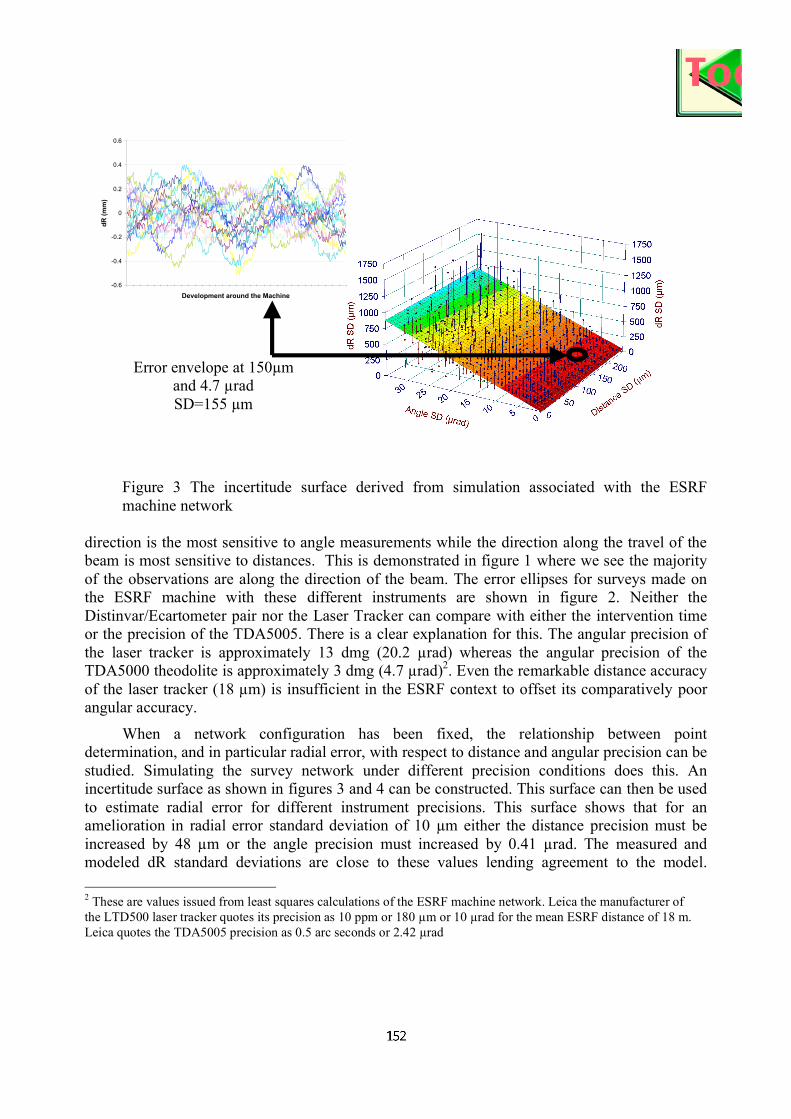
Figure 3 The incertitude surface derived from simulation associated with the ESRFmachine network
direction is the most sensitive to angle measurements while the direction along the travel of thebeam is most sensitive to distances. This is demonstrated in figure 1 where we see the majorityof the observations are along the direction of the beam. The error ellipses for surveys made onthe ESRF machine with these different instruments are shown in figure 2. Neither theDistinvar/Ecartometer pair nor the Laser Tracker can compare with either the intervention timeor the precision of the TDA5005. There is a clear explanation for this. The angular precision ofthe laser tracker is approximately 13 dmg (20.2 µrad) whereas the angular precision of theTDA5000 theodolite is approximately 3 dmg (4.7 µrad)2. Even the remarkable distance accuracyof the laser tracker (18 µm) is insufficient in the ESRF context to offset its comparatively poorangular accuracy.
When a network configuration has been fixed, the relationship between pointdetermination, and in particular radial error, with respect to distance and angular precision can bestudied. Simulating the survey network under different precision conditions does this. Anincertitude surface as shown in figures 3 and 4 can be constructed. This surface can then be usedto estimate radial error for different instrument precisions. This surface shows that for anamelioration in radial error standard deviation of 10 µm either the distance precision must beincreased by 48 µm or the angle precision must increased by 0.41 µrad. The measured andmodeled dR standard deviations are close to these values lending agreement to the model.
2 These are values issued from least squares calculations of the ESRF machine network. Leica the manufacturer ofthe LTD500 laser tracker quotes its precision as 10 ppm or 180 µm or 10 µrad for the mean ESRF distance of 18 m.Leica quotes the TDA5005 precision as 0.5 arc seconds or 2.42 µrad
-0.6
-0.4
-0.2
0
0.2
0.4
0.6
Development around the Machine
dR
(m
m)
Error envelope at 150µmand 4.7 µradSD=155 µm

Because the network is fixed, to improve radial precision, one must improve instrumentaccuracy. The only way to do this is by instrument calibration.
Figure 4 ESRF machine network radial error incertitude surface with different instrumentconfigurations. For comparison, the laser tracker measured standard deviation in dR is 461µm while the TDA5005 is 105 µm.
3. INSTRUMENT CALIBRATION
3.1 Distance Calibration
The ESRF calibration bench is used to determine the zero and cyclic errors of EDMinstrument/reflector pairs. The zero error, or the offset between the distance measured by theinstrument and the true distance, is first determined. Then the instrument prism is moved alongthe bench and distances are measured by the EDM. A photograph of the ESRF calibration benchsetup is shown in figure 5. These distances are compared to simultaneously measuredinterferometer distances. The results are a calibration curve as shown in figure 7 below. AFourier series can model this calibration curve. Residuals with respect to a modeled curve aregenerally less than 0.1 mm. This curve can then be used to correct measured distances. Whenthese corrected distances are used in the least squares adjustment of the machine network there isa net amelioration in the distance standard deviation from 0.18 mm to 0.12 mm and consequent

Interferometer
EDM
EDM Prism
Interferometer Prism
Figure 5 Photograph of the ESRF calibration bench
improvement in the radial error incertitude. Furthermore, the distance residuals become morenormal when the distance calibration is used (refer to figure 8).
It is the intention of the ALGE group to extend the present accreditation for EDMinstruments for distances up to 100 m. At present, tests are being conducted with the mirrors in afixed position at one end of the bench. The theodolite is placed at the other end of the benchlaterally offset by 30 cm from the laser interferometer. The EDM reflector is positioned on thecarriage as usual. The carriage is moved along the bench at 10 cm intervals and simultaneousinterferometer and EDM distances are taken. This method requires that three instrument setupsbe used to ensure overlap in the measurements. Although much work remains, results arepromising with a difference standard deviation between the established calibration and the new100 m calibration in the overlap zones of better that 0.1 mm (see figure 9). This is very close tothe residuals associated with the model shown in figure 6.

Figure 6 Typical calibration curve for an EDM. Deviations from the smooth modeled curveare 0.06 mm.
Figure 7 Distance standard deviations issued from the least squares calculation are morenormal after the calibration model is employed

.
Figure 8 Results for the 100 m calibration. Standard deviations between values in the‘overlapped’ regions are 0.08 mm.
3.2 Angle Calibration
As has been shown, considerable improvement has been made in the distance standarddeviation at the ESRF by employing rigorous calibration techniques. Being at the limit of theTDA5000/5 distance measuring capacity, one can only expect improvement by increasing theaccuracy of the angle measurements. From the discussion on potential achievable precision, onecan expect a dramatic improvement in the radial error incertitude for a comparatively smallimprovement in angle measurement accuracy. Clearly, in the case of the ESRF at least, there is avery strong incentive to improve the angle measuring accuracy. One method of improving angleprecision is to calibrate the angle encoders as is done at Leica.
At the ESRF an angle dependence on distance has been observed3. A second method ofimproving angle accuracy is to model this dependence. One ESRF TDA5005 instrument behavesdifferently from the two others when angles taken at short distances are compared. We havedeveloped an empirical angle correction as a function of distance for this instrument. Whenuncorrected this error has important consequences on the results of the machine radial error. This
3 The manufacturer of this instrument recommends it be used in ATR mode at distances greater that 6 m.This errorconcerns principally distances inferior to this limit.
-0.0351
-0.0350
-0.0349
-0.0348
-0.0347
-0.0346
-0.0345
-0.0344
-0.0343
-0.0342
0 20 40 60 80 100
EDM Distance (m)
Err
or (
m)

angular dependence is shown in figure 9. Moreover, even when corrected, the angle residualsissued from the least squares adjustment are not normally well distributed. For these reasons,recently a method using the ESRF calibration bench has been developed to determine the angularerror of a theodolite as a function of distance. This method appears to work well and will be fullyexploited in the next year in an effort to improve the angle measurements precision. Reults of acalibration are shown in figure 10.
Figure 9 Radial error as a function of instrument used. When uncorrected this error hasimportant consequences on the results of the machine radial error.
Difference in dR between Corrected and Non-corrected Angle Observations for TDA5005-3
-0.25
-0.15
-0.05
0.05
0.15
0.25
0.35
0.45
0.55
SR/A-G
QD8/C1E
SR/A-G
QD1/C2E
SR/A-G
QD8/C3E
SR/A-G
QD1/C4E
SR/A-G
QD8/C5E
SR/A-G
QD1/C6E
SR/A-G
QD8/C7E
SR/A-G
QD1/C8E
SR/A-G
QD8/C9E
SR/A-G
QD1/C10
E
SR/A-G
QD8/C11
E
SR/A-G
QD1/C12
E
SR/A-G
QD8/C13
E
SR/A-G
QD1/C14
E
SR/A-G
QD8/C15
E
SR/A-G
QD1/C16
E
SR/A-G
QD8/C17
E
SR/A-G
QD1/C18
E
SR/A-G
QD8/C19
E
SR/A-G
QD1/C20
E
SR/A-G
QD8/C21
E
SR/A-G
QD1/C22
E
SR/A-G
QD8/C23
E
SR/A-G
QD1/C24
E
SR/A-G
QD8/C25
E
SR/A-G
QD1/C26
E
SR/A-G
QD8/C27
E
SR/A-G
QD1/C28
E
SR/A-G
QD8/C29
E
SR/A-G
QD1/C30
E
SR/A-G
QD8/C31
E
SR/A-G
QD1/C32
E
ddR
(m
m)
Angle Correction TDA5005-3
0
20
40
60
3 7 11Distance (m)
Cor
rect
ion
(dm
g)
The correction applies in the same direction regardless of the orientation of the observation, however, its magnitude varies as a function of distance.
TDA5005-3 observations TDA5005-3 observationsTDA5005-3 observations

Figure 10 Results of a calibration of angles and residuals with respect to a modeled curveas a function of distance for one ESRF TDA5005 total station.
-10
-5
0
5
10
2 7 12 17 22 27
Distance (m)
Dif
fere
nce
wrt
Mo
del
ed C
urv
e (µ
rad
)
-15
-10
-5
0
5
10
15
20
25
30
35
40
2 7 12 17 22 27
Distance (m)
An
gle
Err
or
(µra
d)

4. CONCLUSIONS
The degree of precision to which we can hope to measure a survey network is dependentupon its configuration and the instrumentation used to measure it. At the ESRF considerableefforts have been made to improve instrument precision and in particular distance measurementsby means of calibration. COFRAC accreditation under the ISO/CEI 17025 Norm has ensuredthat the greatest rigor be applied in the calibration techniques used at the ESRF. Measurementshave shown that in order to improve upon alignment accuracy, we must now make an effort toimprove angle measurement precision. We are presently developing an angle calibration methodthat will reduce those errors associated with an observed distance dependence.
5. REFERENCES
[1] Gatta G., Levet N., Martin D., Alignment at the ESRF, Proceedings of the Sixth International Workshop onAccelerator Alignment 1999, Grenoble France.[2] Claret E., Etude de la Base d’Etalonage de l’ESRF, ESGT Le Mans France, July 1999.[3] Zeiske K, Current Status of the ISO Standardization of Accuracy Determination Procedures for SurveyingInstruments, FIG Working Week 2001, Seoul Korea 6-11 May 2001, FIG[4] Maillefaud J.D., Etude De l’etalonnage des Systems de Mesure d’Angle Pour les Theodolites au Sein deL’European Synchrotron Radiation Facility, ENSAIS, Strasbourg France, July 2002