instruction sheet 752-500 - sandc.com · pdf filestructures which must meet specific static...
TRANSCRIPT

S&C Line-Rupters" Outdoor Transmission (115 kv through 230 kv) I For Line and Cable Switching
INSTRUCTIONS For Field Assembly and Installation
ITABLE OF CONTENTS I Section Page Number Section Page Number INTRODUCTION ........................................ 1 INSTALLING THE INTERPHASE SHAFT .................. .13 BEFORE STARTING INSTALLATION ...................... . 3 INSTALLING THE OPERATOR. .......................... ,15 ASSEMBLY OF INDIVIDUAL POLE-UNITS. ................. . 4 FINAL CHECKS AND ADJUSTMENTS .................... .16
I INTRODUCTION 1
The equipment covered by this publication must be selected for a specific application and it must be installed, operated, and maintained by qualified persons who are thoroughly trained and who understand any hazards that may be involved. This publication is written only for such qualified persons and is not intended to be a substitute for adequate training and experience in safety procedures for this type of equipment.
General The following instructions are for field assembly (erec- tion) and installation of S&C Line-Rupters. See Figure 1.
The S&C Line-Rupter employs an in-series circuit- breaking interrupter and a circuit-making and isolating disconnect, making it especiallysuited for line and cable switching; specifically, load splitting (parallel or loop switching), load dropping, and line and cable dropping. Line-Rupter is capable of closing, carrying, and interrupting load currents and parallel or loop currents, as well as line- and cable-charging current.
Line-Rupters utilize the time-proven reliability of the S&C Circuit-Switcher's brain and in-series interrupter, combined in a compact, economical, minimum- maintenance switching package. Line-Rupter interrupt- ers are economically tailored for specific applications by employing the precise number of interrupting gaps required.
Each pole-unit of the S&C Line-Rupter includes a brain which provides built-in positive sequence control . . . and a fully enclosed stored-energy source dedicated solely to operation of the interrupter which
is in the circuit at all times. Close-and-trip mechanisms are fully enclosed and protected, too. There are no external linkages, lever arms, cams, shunts, etc. that must be coordinated with a disconnect blade to accom- plish circuit interruption. Positively sequenced oper- ation is assured regardless of severe weather conditions such as high winds, rain, sleet, or snow.
Line-Rupters can be manually operated by means of an S&C Manual Geared Operating Handle. Alternately, for remote supervisory control, power operation can be provided with an S&C Switch Operator-Type LS-2. For manually operated Line-Rupters, the degree of simultaneity of opening and closing of the three pole- units depends on the proper installation and adjust- ment of the operating mechanism-as well as on the speed of cranking at the operating handle-and must be considered in establishing ground-relay settings.
Mounting of Line-Rupters S&C Line-Rupters are intended for upright mounting on S&C Mounting Pedestals or, alternately, for upright mounting on the user's steel pedestals or supporting structures which must meet specific static deflection limits shown in an S&C data sheet.
The weight of the bus plus any associated ice load exerts a vertical force on upright-mounted Line-Rupter terminal pads. This vertical force must not exceed 400 pounds on either terminal pad.
Seismic Withstand Capability S&C Line-Rupters, when installed with the recom- mended S&C Mounting Pedestals and anchor bolts, are capable of withstanding seismic loading of 0.2 ground
Supersedes lnstructlon Sheet 752-500 dated 4-21-86 '1991
INSTRUCTION SHEET 7521500 S&C ELECTRIC COMPANY 4 Chicago Page 1 of 17 S&C ELECTRIC CANADA LTD. Toronto December 16,1991

S&C Line-Rupters’”I
For Line and Cable SwitchingOutdoor Transmission (115 kv through 230 kv)
INTRODUCTION - Continued
acceleration in any direction, as well as performing asintended during such loading and afterward. Higherseismic withstand capabilities can be furnished onspecial application.
Inspection Schedule and ProceduresTo assure Line-Rupter’s continued proper performance,it should be inspected in accordance with S&C’s
I
recommended schedule and procedures contained inS&C Instruction Sheet 752-590.
Since the Type LS-2 Switch Operator is provided witha convenient means for decoupling it from the Line-Rupter, elective exercising of the operator may beperformed at any time without requiring an outage orswitching to an alternate source.
3 4-r I.__ ---I--I d-n* ------- ---~:-III~IIS: mnnuallv aaerated. and mounted on S&CFigure 1. S&C Line-Rupter ratea I 13 KV nommal, IL”” alllperv:rr GVIIIIIIL---, . ..-..--... -r -.--- -, -..- ..- -
Mounting Pedestals.
752400 1~s~~ucm0N SHEETPage 2 of 17December 16,199l
S&C ELECTRIC COMPANY l ChicagoS&C ELECTRIC CANADA LTD. l Toronto

IBEFORE STARTING INSTALLATION 1 Checking the Shipment An S&C erection drawing will be found in a water- resistant envelope attached to the interrupter con- tainer on one of the three Line-Rupter pole-units. Study the erection drawing carefully and check the bill of material to be sure all parts are at hand.
The Line-Rupter shipment should include the following items, as shown in Figure 2: 1.
2. 3.
4. 5.
6.
Three pole-units, each mounted on a skid, with the live parts attached directly to the insulator- mounting flanges; Insulators, shipped in separate crates; Miscellaneous operating-mechanism components including a temporary adapter for hand operation of the individual pole-units; Interphase and vertical operating pipe; An S&C Manual Geared Operating Handle (if specified) or an S&C Switch 0perator"Type LS-2 (if specified, in place of a manual geared operating handle); S&C Mounting Pedestals (if specified).
@ Interrupter Target Line-Rupters are usually shipped with the interrupters in the open position. Therefore, the interrupter target, located on the side of each brain housing (see Figure S), will appear yellow. During the step-by-step instructions which follow, the disconnect blades will be moved to the fully open position. This will close the interrupter and charge and latch the stored-energy source within the brain, and the target will appear gray (normal).
When in service, Line-Rupter interrupters should never be open when the blades are in the closed position. To close the interrupters, Line-Rupter must be completely opened and then reclosed.
Gas-Pressure Indicator Line-Rupters have sealed interrupters containing gas under pressure. Loss of gas pressure may result in improper interrupting action. Low gas pressure is signaled by a red target in the gas-pressurc indicator at the terminal end of each interrupter. See Figure 2. A gray target indicates normal pressure.
DO NOT INTERMIX COMPONENTS FROM DIFFERENT INSTALLATIONS
S&C maintains an historical record-by serial number-of every Line-Rupter produced. This record lists information pertinent to each instal- lation, such as application, date of shipment, and any service performed by S&C factory service specialists. This record is invaluable when questions arise relative to modifkations or replacements. I t is important, therefore, that the various compo- nents belonging to a specific Line-Rupter installa- tion not be intermixed with components belonging to a different installation.
For this reason, each Line-Rupter is serially numbered. This serial number is stamped on the nameplate affixed to each individual pole-unit base and also on the nameplate affixed to the manual geared operating handle (or to the switch operator if the Line-Rupter is power operated).
To facilitate identification during erection, the serial number, the sales-order number, and the erection-drawing (ED) number are marked on the top face of each Line-Rupter pole-unit base; on each pole-unit shipping crate or skid; and on all crates, boxes, and bundles for the other components associated with the installation.
Please complete and mail the Line-Rupter registration card (enclosed in the water-resistant envelope) after the Line-Rupter has been installed. The information requested on this card is vital to ensure prompt notification in the event field modifications are needed.
INSTRUCTION SHEET 752m500 S&C ELECTRIC COMPANY Chicago Page 3 of 17 S&C ELECTRIC CANADA LTD. Toronto December 16,1991

Do not remove the interrupter containers until theinstallation has been completed.
PIERCING SET SCREWSTo assure the integrity of the operating mechanism,it is imperative that careful attention be given tothe correct installation of the piercing set screwsprovided on operating-pipe couplings and pipeclamps. Before installing operating pipe in anycoupling or clamp, make certain that the cuttingtip of the piercing set screw does not protrudethrough the body of the coupling or clamp. Tighteneach piercing set screw as directed in the step-by-step instructions that follow, but in each case, onlyafter the associated clamp bolts have been torquedto final tightness.
S&C Line-Rupters’”Outdoor Transmission (115 kv through 230 kv) I
For Line and Cable Switching
ASSEMBLY OF INDIVIDUAL POLE-UNITS
step 1
I
Make sure that each shipping skid rests firmly and isreasonably level. If the ground is uneven, shoring underthe skids is necessary.
Carefully remove the outer crates (if provided), butleave the skids attached to the pole-unit bases. SeeFigure 2. Remove any live-part blocking members andstraps.
Inspect for any obvious shipping damage beforecontinuing installation.
Repeat the folkming Steps 2 through 20 for each ofthe Line-Rupter pole-units.
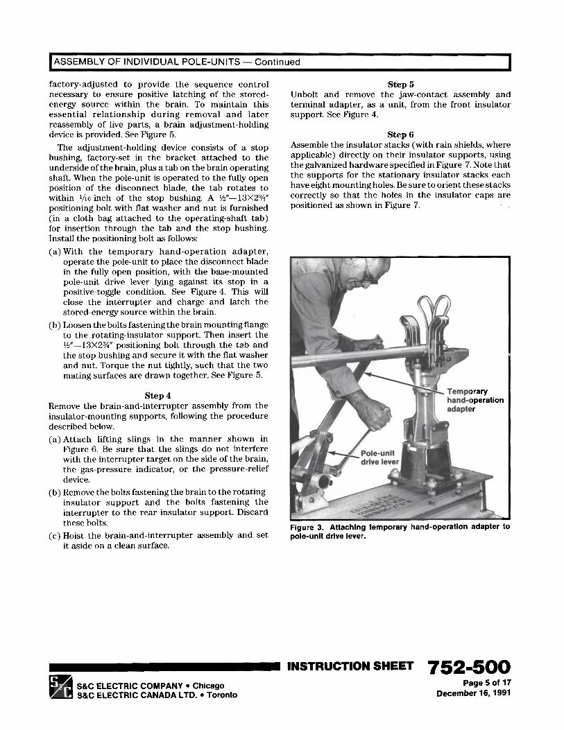
Step 2Attach the temporary hand-operation adapter, whichis provided, to the pole-unit drive lever, as shown inFigure 3.
step 3Each Line-Rupter pole-unit brain, conjointly with itsassociated base-mounted operating mechanism, is
4
Instructions and regfrtration card inwater-reslstdnt envelope /--
Disconnect
Pressure-relief deviceInterrupter
/
h-tsulator hardware
L Interrupter target
Figure 2. Pole-unit on skid.
752400 INSTRUCTION SHEETPage 4 of 17December 16,199l
S&C ELECTRIC COMPANY l ChicagoS&C ELECTRIC CANADA LTD. l Toronto
[ASSEMBLY OF INDIVIDUAL POLE-UNITS - Continued I
factory-adjusted to provide the sequence controlnecessary to ensure positive latching of the stored-energy source within the brain. To maintain thisessential relationship during removal and laterreassembly of live parts, a brain adjustment-holdingdevice is provided. See Figure 5.
The adjustment-holding device consists of a stopbushing, factory-set in the bracket attached to theunderside of the brain, plus a tab on the brain operatingshaft. When the pole-unit is operated to the fully openposition of the disconnect blade, the tab rotates towithin r/16 inch of the stop bushing. A %“-13X23/4”positioning bolt with flat washer and nut is furnished(in a cloth bag attached to the operating-shaft tab)for insertion through the tab and the stop bushing.Install the positioning bolt as follows:(a) With the temporary hand-operation adapter,
operate the pole-unit to place the disconnect bladein the fully open position, with the base-mountedpole-unit drive lever lying against its stop in apositive-toggle condition. See Figure 4. This willclose the interrupter and charge and latch thestored-energy source within the brain.
(b) Loosen the bolts fastening the brain mounting flangeto the rotating-insulator support. Then insert the%“-13X2%” positioning bolt through the ta”b andthe stop bushing and secure it with the flat washerand nut. Torque the nut tightly, such that the twomating surfaces are drawn together. See Figure 5.
Step 4Remove the brain-and-interrupter assembly from theinsulator-mounting supports, following the proceduredescribed below.
(a
@
Attach lifting slings in the manner shown inFigure 6. Be sure that the slings do not interferewith the interrupter target on the side of the brain,the gas-pressure indicator, or the pressure-reliefdevice.Remove the bolts fastening the brain to the rotating-insulator support and the bolts fastening theinterrupter to the rear insulator support. Discardthese bolts.
(c) Hoist the brain-and-interrupter assembly and setit aside on a clean surface.
Step 5Unbolt and remove the jaw-contact assembly andterminal adapter, as a unit, from the front insulatorsupport. See Figure 4.
Step 6Assemble the insulator stacks (with rain shields, whereapplicable) directly on their insulator supports, usingthe galvanized hardware specified in Figure 7. Note thatthe supports for the stationary insulator stacks eachhave eight mounting holes. Be sure to orient these stackscorrectly so that the holes in the insulator caps arepositioned as shown in Figure 7.
w Temporaryhand-operation
Figure 3. Attaching temporary hand-operation adapter topole-unit drive lever.
INSTRUCTION SHEET 752-500q S&C ELECTRIC COMPANY l ChicagoS&C ELECTRIC CANADA LTD. l Toronto
Page5of 17December 16,199l

S&C Line-Rupters’”I
For Line and Cable SwitchingOutdoor Transmission (115 kv through 230 kv)
ASSEMBLY OF INDIVIDUAL POLE-UNITS - Continued I
Step 7 (d) Operate the temporary hand-operation adapterCheck the rotating insulator stack for eccentricity as and check to see that the mark on the cord remainsfollows: within $6 inch of the centerpoint of the rotating
(a) Locate the centerpoint of each insulator stack by insulator cap as the insulator stack turns. Any
accurately drawing, on the top of the insulator cap, eccentricity in excess of this value must be corrected
temporary lines which bisect and connect opposite by placing shims between the insulator stack and
bolt holes. See Figure 7. its support. See Figure 7. Shimming material is
(b) Stretch a cord taut across the top of the insulatorinejuded with the insulator hardware in a cloth sack
caps so that it crosses the centerpoint on theattached to the pole-unit base.
rotating insulator stack. (At this tune the cord need Torque to final tightness all insulator-stack capnot cross the centerpoint of the front and rear scrms, including those fastening the insulator stacksinsulator caps.) to the insulator supports.
(c) Make a mark on the cord at the point where it When adjustments have been made to eliminate
crosses the centerpoint of the rotating insulator eccentricity, the perpendicularity of the rotating
stack.
. Jaw-contactassembly
Terminal adapter
Front insulator
Figure 4. Using the temporary hand-operation aaapter to operate ,,,r p”l~:-“lw, I” ll,C ups,, pvrmllvll.
752-500 INSTRUCTION SHEETPage 6 of 17 S&C ELECTRIC COMPANY. Chlcago -
December 16,199l S&C ELECTRIC CANADA LTD. l Toronto q

ASSEMBLY OF INDIVIDUAL POLE-UNITS - ContinuedI
‘h” -13X2%”positioning bolt 1
Factory-set stop bushing
J
Wonbrainshaft ’ Loose”t~o,‘~L~z~~~,
IL5 ue,o,t!r tightening positicming bolt
Brain mountingflange
Figure 5. Installing the positioning bolt in the brain adjustment-holding device.
Pressure-relief device
Gas-pressure indicator
Rotating insulator support
Rear insulator support
Figure 6. Removing brain-and-interrupter assembly from insulator-mounting suppons.
m S&C ELECTRtC COMPANY l ChicagoS&C ELECTRIC CANADA LTD. l Toronto
INSTRUCTION SHEET ‘752m5mPage 7 of 17
December 16,199l

S&C Line-Rupters’”I
For Line and Cable SwitchingOutdoor Transmission (115 kv through 230 kv)
ASSEMBLY OF INDIVIDUAL POLE-UNITS - Continued
insulator stack with respect to the base will be withinacceptable limits.
Step 8The rear insulator stack should be checked foralignment with the rotating insulator stack as follows:(a) Stand behind the rear insulator stack and sight
down the length of the pole-unit base. The rearinsulator stack should not be canted. It should beperpendicular to the base and in alignment withthe rotating insulator stack.
(b) Measure the centerline distance across the top fromthe centerpoint of the rotating insulator stack tothe centerpoint of the rear insulator stack. Thismeasurement must be within l/s inch of the dimen-sion shown on the erection drawing. See Figure 7.
Step 9
(a) Loosen the four locking nuts and adjust the levelingscrews located under the stationary insulatorsupport. See Figure 7. (The leveling screws arethreaded into the insulator-support flange.) Toavoid changing the effective height of the insulatorstack, do not use more than three of thefour levelingscrews fin- this adjustment.
(b) Retighten the four locking nuts.
Step 10Check the alignment of the front insulator stack bymeans of a cord stretched taut across the top of theinsulator stacks. The cord should cross the centerpointsof all three insulator stacks, and the front insulatorstack should not be canted. If adjustment of the frontinsulator stack is necessary, follow the proceduredescribed in Step 9.
Adjust for the necessary centerline distance and thestack alignment, as described in Step 8, as follows:
Within % inchof dimensionshown on erec-
Insulator stacks
- - - - -- - Rear insulator cap- -e >c‘&=
Rotating insulatorstack must beperpendicular tobase. Use shimshere if required.See Step 7
*insulator cap
lockwashersLocking nuts
Figure 7. Critical dimension and alignment to be attained using snlms ana leveung screws.
752400 INSTRUCTION SHEETPage 8 of 17December 18,199l
S&C ELECTRIC COMPANY l ChicagoS&C ELECTRIC CANADA LTD. l Toronto

ASSEMBLY OF INDIVIDUAL POLE-UNITS - Continued
step11 See Figure 8. Be sure to place the brain-and-Mount the brain-and-interrupter assembly as follows: interrupter assembly on the same pole-unit from(a) So that the brain may be attached in its proper which it was removed.
relationship to the rotating insulator stack, place (c) Install the cap screws (with lo&washers) fingerthe base-mounted operating mechanism in the tight at both ends of the brain-and-interrupter“disconnect-blade-opened” position with the pole- assembly. See Figure 8. Make sure that alignmentunit drive lever against its stop bolt (rotating is such that the cap screws enter freely. If necessary,insulator rotated counterclockwise as viewed from reposition the rear stationary insulator stack usingthe top). Make sure that the drive lever is held in the leveling screws. Also, if necessary, loosen thethis position during the remainder of this step. cap screws at the rotating-insulator support. Then,
(b) Lift the brain-and-interrupter assembly into with the pole-unit drive lever against its stop boltposition on its respective insulator stacks (brain as described in (a) above, torque to final tightness,attaches to rotating insulator), using the same in order, the interrupter cap screws at the terminalhandling care that was cautioned for its removal. end, the cap screws at the top of the rotating
5/a”-11X1%"hex-head galvanized Asteel cap screwsand lockwashers C
\ \
. .Figure 8. Lifting brain-and-interrupter assembly into place. Inset shows jaw-contact assembly and terminal adapter beingplaced.
INSTRUCTION SHEET 7521500S&C ELECTRIC COMPANY l ChicagoS&C ELECTRIC CANADA LTD. l Toronto
Page 9 of 17December 16,1991

S&C Line-Rupters’”I
For Line and Cable SwitchingOutdoor Transmission (115 kv through 230 kv)
ASSEMBLY OF INDIVIDUAL POLE-UNITS - Continued 1
insulator stack, and, finally, any rotating-insulator cap screws previously loosened.
step 12Remove, from the adjustment-holding device under thebrain, the Yz”-13x2s” positioning bolt installed inStep 3. (A visible gap between mating parts is normalwhen the bolt is removed.)
Do not attempt to operate the Line-Rupter pole-unitbefore removing the positioning bolt.
Step 13Mount the jaw-contact assembly and terminal adapteras a unit on the front insulator stack using thegalvanized hardware specified in Figure 8. Align thejaw-contact assembly with the blade by shifting theterminal adapter as required. See Figure 8. (Optimumalignment of the jaw-contact assembly with the blademay require adjustment of the front-insulator-supportleveling screws. This final adjustment should be madeonly after the pole-unit has been mounted in place andbolted to the pedestals or structure.)
Step 14With the temporary hand-operation adapter, operatethe pole-unit to the closed position. Attach lifting slings
to the pole-unit base and unbolt the base from the skid.Raise the pole-unit to its mounting position as shownon the erection drawing. Make sure that the riggingdoes not stress the interrupter or the brain. Further-more, extreme care should be exercised to prevent thelifting slings or fall lines from interfering with theinterrupter target, the gas-pressure indicator, or thepressure-relief device during erection, and to preventcontact with other objects during lifting.
Do not lift a complete Line-Rupter pole-unit by thedisconnect blade and/or the interrupter.
step 15Bolt the Line-Rupter pole-unit in place using %-inchgalvanized bolts, flat washers, lo&washers, and nuts(furnished only if so specified on order). See Figure 9.The pole-unit base should be shimmed as required ifthe mounting surface is sufficiently irregular to distortthe base.
Step 16Make a final check of the Line-Rupter pole-unit foradjustment and alignment of the blade with the jaw-
Figure 9. Complete pole-unit, after mounting on structure.
752-500 INSTRUCTION SHEETPage 10 of 17December 16,lQQl
S&C ELECTRIC COMPANY l ChicagoS&C ELECTRIC CANADA LTD. l Toronto
ASSEMBLY OF INDIVIDUAL POLE-UNITS - Continued
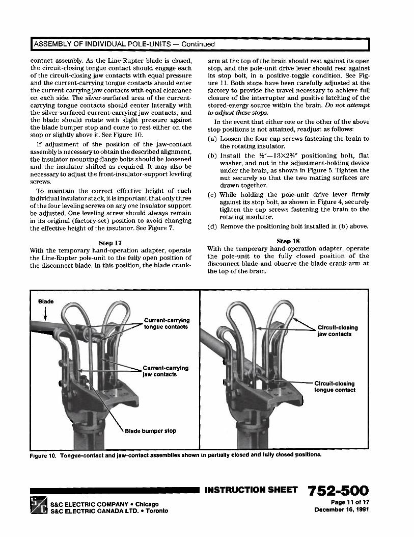
contact assembly. As the Line-Rupter blade is closed,the circuit-closing tongue contact should engage eachof the circuit-closing jaw contacts with equal pressureand the current-carrying tongue contacts should enterthe current-carrying jaw contacts with equal clearanceon each side. The silver-surfaced area of the current-carrying tongue contacts should center laterally withthe silver-surfaced current-carrying jaw contacts, andthe blade should rotate with slight pressure againstthe blade bumper stop and come to rest either on thestop or slightly above it. See Figure 10.
If adjustment of the position of the jaw-contactassembly is necessary to obtain the described alignment,the insulator mounting-flange bolts should be loosenedand the insulator shifted as required. It may also benecessary to adjust the front-insulator-support levelingscrews.
To maintain the correct effective height of eachindividual insulator stack, it is important that only threeof the four leveling screws on any one insulator supportbe adjusted. One leveling screw should always remainin its original (factory-set) position to avoid changingthe effective height of the insulator. See Figure 7.
arm at the top of the brain should rest against its openstop, and the pole-unit drive lever should rest againstits stop bolt, in a positive-toggle condition. See Fig-ure 11. Both stops have been carefully adjusted at thefactory to provide the travel necessary to achieve fullclosure of the interrupter and positive latching of thestored-energy source within the brain. Do not attemptto adjust these stops.
In the event that either one or the other of the abovestop positions is not attained, readjust as follows:(a) Loosen the four cap screws fastening the brain to
the rotating insulator.(b) Install the %“-13X2%” positioning bolt, flat
washer, and nut in the adjustment-holding deviceunder the brain, as shown in Figure 5. Tighten thenut securely so that the two mating surfaces aredrawn together.
(c) While holding the pole-unit drive lever firmlyagainst its stop bolt, as shown in Figure 4, securelytighten the cap screws fastening the brain to therotating insulator.
(d) Remove the positioning bolt installed in (b) above.
step 17With the temporary hand-operation adapter, operatethe Line-Rupter pole-unit to the fully open position ofthe disconnect blade. In this position, the blade crank-
Step 18With the temporary hand-operation adapter, operatethe pole-unit to the fully closed position of thedisconnect blade and observe the blade crank-arm atthe top of the brain.
Current-carryingtongue contacts
Current-carrying
Blade bumper stop
\r/+Circuit-closing
jaw contacts
7 Circuit-closingtongue contact
Figure 10. Tongue-contact and jaw-contact assemblies shown In partially closed and tully closea positions.
INSTRUCTION SHEET 752m5()0pd S&C ELECTRIC COMPANY l Chicago
S&C ELECTRIC CANADA LTD. l TorontoPage 11 of 17
December 16,199l
S&C Line-Rupters’”I
For Line and Cable SwitchingOutdoor Transmission (115 kv through 230 kv)
ASSEMBLY OF INDIVIDUAL POLE-UNiTS - Continued 1
Although it is desirable that the blade crank-arm restagainst its closed stop when the disconnect blade isin the fully closed position, a gap not greater thanl/32 inch can be tolerated in the closed position only.
step 19Check the Line-Rupter pole-unit for adequate penetra-tion of the blade into the jaw contact during completionof the closing stroke. See Figure 10. The blade shouldexert a slight pressure against the blade bumper stopbefore the start of the “wiping in” rotation. After thecurrent-carrying tongue contacts are completelyrotated into the jaw contacts, the blade pressure againstthe bumper stop will tend to be relaxed, and a %-inchmaximum gap is permissible between the blade andthe blade bumper stop.
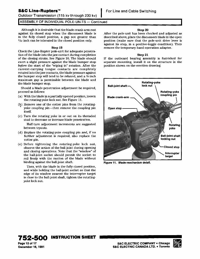
Should a blade-penetration adjustment be required,proceed as follows:(a) With the blade in a partially opened position, loosen
the rotating-yoke lock nut. See Figure 11.@) Remove one of the cotter pins from the rotating-
yoke coupling pin-then remove the coupling pinitself.
(c) Turn the rotating yoke in or out on its threadedstud to decrease or increase blade penetration.
Half-turn adjustment increments are suggestedbetween tryouts.
(d) Replace the rotating-yoke coupling pin and, if nofurther adjustment is required, also replace thecotter pin.
(e) Before tightening the rotating-yoke lock nut,observe the action of the ball joint during openingand closing operations. Note that the “window” ofthe ball-joint socket should permit the socket toroll freely with the motion of the blade withoutbinding against the ball-joint shaft.
Then, with the blade in the fully closed position,and while holding the ball-joint socket so that theedge of its window nearest the interrupter targetis close to the ball-joint shaft, tighten the rotating-yoke lock nut.
Step 20After the pole-unit has been checked and adjusted asdescribed above, place the disconnect blade in the openposition (make sure that the pole-unit drive lever isagainst its stop, in a positive-toggle condition). Thenremove the temporary hand-operation adapter.
step 21If the outboard bearing assembly is furnished forseparate mounting, install it on the structure in theposition shown on the erection drawing.
Ball-joint shaftRotating-yokelock nut
\ Rotating-yoke
Blade crank-arm
Open stop -
\ coupling pin
Ball-joint-shaft
Figure 11. Blade-mechanism detail.
7521500 INSTRUCTION SHEETPage 12 of 17December 16,199l
S&C ELECTRIC COMPANY l ChicagoS&C ELECTRIC CANADA LTD. l Toronto

I INSTALLING THE INTERPHASE SHAFT
step 22 Note: The base-mounted open stop bolt for each pole- unit drive lever is factory-adjusted to achieve the travel (and positive-toggle condition) necessary to ensure positive latching of the stored-energy source within the brain. Do not change this stop adjustment.
Install the interphase shaft as follows: (a) Remove the clamps from the interphase-shaft drive
lever and from the three pole-unit drive levers. See Figure 12 for identification.
(b) Place the interphase shaft in the saddles of the three pole-unit drive levers (positioned as shown on the erection drawing), but do not attach the clamps at this time.
(c) Place the interphase-shaft drive lever against the interphase shaft. Mark the lever position on the shaft. See Figure 12 (top). Rotate the outboard bearing to swing the interphase-shaft drive lever into a position in which the clamp can be easily reattached. Lift the interphase shaft out of the pole- unit saddles and place it in the saddle of the interphase-shaft drive lever-at the previously marked position. See Figure 12 (center). Attach the
interphase-shaft drive lever clamp and securely tighten the clamp bolts equally so that the clamp pulls down evenly. Then tighten the clamp’s piercing set screw, piercing the pipe, and continue turning until a firm resistance is felt. Again rotate the outboard bearing and, at the same time, lift the interphase shaft back into the saddles of the three pole-unit drive levers. In that position, tighten- in the manner described above-the now accessible piercing set screw in the intephase-shaft drive lever.
(d) Make sure that all three pole-unit drive levers are against their base-mounted stops (each pole-unit drive linkage is then in a positive-toggle condition). Also make sure that the outboard bearing lever is in the switch-open position, with the stop bolt set for approximately 3 degrees of over-center travel-to provide positive toggle at this point as well. Then reinstall the clamps on the three pole- unit drive levers. Tighten the clamp bolts equally so that the clamps pull down evenly. See Figure 12 (bottom). Do not, hmuever , tighten the piercing set screws for the pole-unit drive levers until so directed i n Step 27.
INSTRUCTION SHEET 752-500 S&C ELECTRIC COMPANY Chicago Page 13 of 17 S&C ELECTRIC CANADA LTD. Toronto December 16,1991

S&C Line-Rupters”I
For Line and Cable SwitchingOutdoor Transmission (115 kv through 230 kv)
INSTALLING THE INTERPHASE SHAFT - Continued
Pole-unit drive leverclamp (removed)
Pole-unit drlve lever
Interphase-shaft
Marking of lever positionon interphase shaft
Interphase shaftlifted into saddledrive lever
has been! of
Pole-unlt drtve lever ctampis replaced and clamp boltsanrl nipTr:-- --, ----...
Outboard bearing leveragainst (loosened)open stop
Interphase-shaft drivelever clamp (removed)
___-_-._ J.s~~lll~ 1S.FI
against its closed stop
Pole-unit drive lever ctampIS replaced and clamp boltsare tiqhtenetj. Piercinn set V!WWS
are not to be tight+%: ;%~&&-27
All three pole-unit drive levers to beaaains+ ripen stop bolts (stops are
?t-do not adjust)
Figulre 12. Installing the interphase shaft.
) Outboard bearing leveragainst its open stop
djust stop bolt to allow,Gproximately 3-degrees over-onntor travel in ----:I-
7521500 INSTRUCTION SHEETPage 14 of 17December 16,199l S&C ELECTRIC COMPANY l Chicago .S&C ELECTRIC CANADA LTD. l Toronto q

INSTALLING THE OPERATOR I
Step 23 Step 24Attach a universal coupling to the hex shaft extendingbelow the outboard bearing assembly.
Note: If more than one section of vertical pipe isrequired, the upper section(s) with associated cou-pling(s), guide bearing(s), and thrust bearing(s) shouldbe installed first, in accordance with the directionsshown on the erection drawing.
Make certain that all coupling clamp bolts for thevertical operating pipe are securely tightened. Thentighten the piercing set screws for the verticaloperating-pipe couplings and for the manual gearedoperating handle, piercing the pipe, and continueturning until a firm resistance is felt.
Step 26
If an S&C Switch Operator-Type LS-2 is to be used,install it as directed in S&C InstructionSheet 753-500, furnished with the switch operator.If an S&C Manual Geared Operating Handle is tobe used, install it as directed in S&C InstructionSheet 719530, furnished with the operating handle.
Attach one end of the grounding strap to the lowestvertical operating-pipe section with the U-bolt connec-tor furnished. Then connect the other end of thegrounding strap to a suitable earth ground. (S&CMounting Pedestals include, for this purpose, a tabwelded to the pedestal adjacent to the handle location,and a separate grounding connection near the baseof the pedestal for the user’s earth ground.)
Auxiliary switchI-.. m* .- “lx “-Q”)(r;atalog Numoer bun
Key interlock(Catalog Number Suffix ‘I-L”) Output shaft and
flexible coupling
“OPEN” positionIndicator
“CLOSED” position indlcato
Padlocking ’provision
Terminal block (included’with optional auxiliary switch)
Conduit-entrance plate
Figure 13. S&C Manual Geared Operating Handle.
INSTRUCTION SHEET 752-500S&C ELECTRIC COMPANY l ChicagoS&C ELECTRIC CANADA LTD. l Toronto
Page 15 of 17December 16,199l

S&C Line-Rupters’”I
For Line and Cable SwitchingOutdoor Transmission (115 kv through 230 kv)
FINAL CHECKS AND ADJUSTMENTS I
Step 26Using the manual geared operating handle (or themanual operating handle on the switch operator, asappropriate), open and close the Line-Rupter to checkthe manual three-pole group operation. Make sure thatthe following conditions exist:l During the opening sequence, the interrupter target
on the side of each brain vhanges from gray to yellowwhen the interrupter opens, then back to gray,indicating the normally closed position of theinterrupter. In addition, the interrupter targetsremain gray when the Line-Rupter is closed,indicating that the interrupters are closed.
l With Line-Rupter’s disconnect blades in the fullyclosed position, verify that the outboard-bearing leveris against its corresponding stop. Reset the stop ifnecessary.
l While it is not critical, the normal blade opening is90 degrees. It may be desirable from an appearancestandpoint, however, for all three pole-unit blades
to achieve an equal stance when fully open. If, forthis reason, adjustment is required, loosen the ball-joint-shaft locking nut. Turn the shaft (which is aneccentric) to achieve a satisfactory blade position.See Figure 11. Retighten the locking nut. Note thatit is not necessary to loosen the socket-head screw(in the blade crank-arm) to make the aboveadjustment. It is not a lock screw.
Repositioning the ball-joint shaft will affect thedepth of blade penetration into the jaw contactduring completion of the closing stroke. Thedifference in penetration will range from very slight(at lower voltage ratings) to significant (at the highervoltage ratings).
If the adjustment described above is performed,recheck for proper blade penetration and readjustif necessary (as in Step 19).
0 With the disconnect blades in the fully open position,the pole-unit drive lever on each Line-Rupter base
Contact (closed)
Roller
Inner gear
Cam (lowered towardadjacent spring)
Adjacent spring
Figure 14. Adjustment of cams on auxiliary switch.
752-500 INSTRUCTION SHEETPage 16 of 17 S&C ELECTRIC COMPANY l ChicagoDecember 16,199l S&C ELECTRIC CANADA LTD. l Toronto

I FINAL CHECKS AND ADJUSTMENTS - Continued I lies against its stop bolt in a positive-toggle condition, and the blade crank-arm at the top of each brain makes contact with its stop. See Step 11. If this is not the case, it will be necessary to isolate the pole- unit(s) affected by loosening the clamp which fastens the pole-unit drive lever to the interphase shaft. Then, for each affected pole-unit, proceed as follows: (a) Loosen the four bolts fastening the brain to the
rotating insulator stack. (b) Insert the %"-13X2%" positioning bolt through
the tab and the stop bushing at the brain mounting flange and fasten securely, as described in Step 3.
(c) Place the pole-unit drive lever against its stop bolt and tighten the clamp at the interphase shaft. Then tighten the four bolts which fasten the brain to the rotating insulator stack.
(d) Remove the positioning bolt installed in (b) above. If the above conditions are not met, contact the
nearest S&C Sales Office for corrective instructions.
Step 27 When operatiov is satisfactory, tighten the piercing set screws at all three pole-unit drive levers, piercing the pipe, and continue turning until a firm resistance is felt.
Then verify that the clamp bolts and piercing set screws at all locations are fully tightened.
Step 28 Crank the Line-Rupter to its fully open position and then to its fully closed position. In each position, set the corresponding "OPEN" and "CLOSED" position indicators at the output shaft of the manual geared operating handle (or at the output shaft of the switch operator).
Step 29 If the S&C Manual Geared Operating Handle is furnished with an auxiliary switch, catalog number suffix "-Q" or "-W," it will be mounted inside the operating-handle enclosure, alongwith a terminal block for user's connections. See Figure 13. Each auxiliary- switch contact is operated by a cam-actuated roller. A contact is closed if its roller is disengaged from a cam and, conversely, a contact is open if its roller is engaged by a cam. The cams are individually adjustable in 4.5-degree increments. Adjustment of the cams is accomplished as follows: (a) Raise (or lower) the cam toward its adjacent spring
until the cam is separated from the teeth of the inner gear. See Figure 14.
(b) Rotate the cam to advance or retard engagement
(c) Lower (or raise) the cam making sure that the teeth with its roller.
are in mesh with the inner gear.
Step 30 Connect high-voltage conductors to their respective Line-Rupter terminal pads.
Conductors must be de-energized and grounded in accordance with standard system operating practice.
~~~~ ~ ~~ ~
Step 31 Remove the container from each interrupter as follows:
Remove and discard the Yi""16 zinc-plated serrated hex nuts which run the length of the container. Remove and discard the YLif-l6X7/S" and two %"-16X1" zinc-plated hex-head cap screws and flat washers which attach the upper container-half to the coupling end casting of the interrupter. Also remove and discard the three 3/S"-l6X%" and two %"-16X1" zinc-plated hex-head cap crews and flat washers which attach the upper container-half to the indicator end casting of the interrupter. Pry the cor.tainer-halves apart with a screwdriver. The upper container-half can now be removed and discarded-slotted holes are provided so that a rope or lifting sling can be attached and the container-half more conveniently lowered to the ground. Now remove and discard the 3/8"-16X7/g" hex-head cap screw and flat washer which attach the lower container-half to the coupling end casting of the interrupter, and the 3/""16X?/" hex-head cap screw and flat washer which attach the lower container-half to the indicator end casting of the interrupter. Then discard this container-half. Finally, remove and discard the foam-core inner liner wrapped around the iuterrupter.
Now remove the shield for the pressure-relief device.
step 32 Please complete and mail the Line-Rupter registration card! The information requested on this card is vital to ensure prompt notification in the event field modifications are needed.
INSTRUCTION SHEET 752-500 S&C ELECTRIC COMPANY Chicago Page 17 of 17 S&C ELECTRIC CANADA LTD. Toronto December 16,1991
*