instruction manual - hobbicomanuals.hobbico.com/flz/flza4320-4322-manual.pdf · turn the fl ap...
TRANSCRIPT
FLZA4320 / FLZA4322
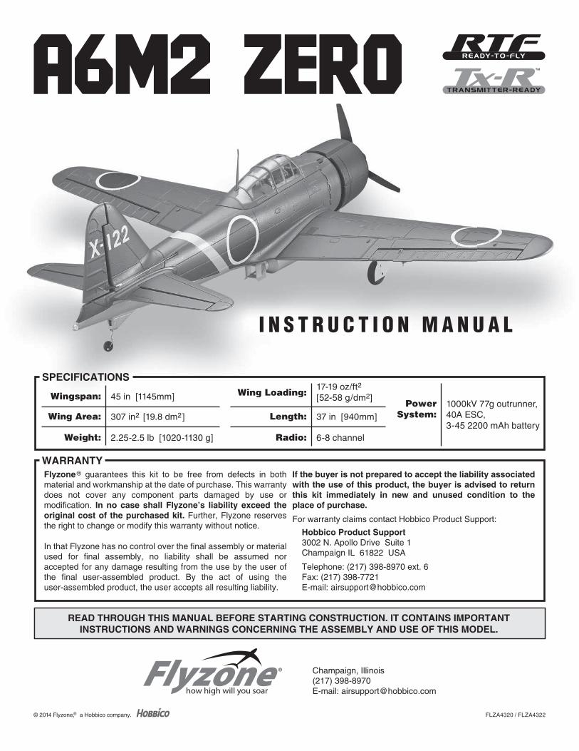
SPECIFICATIONS
PowerSystem:
1000kV 77g outrunner,40A ESC,3-45 2200 mAh battery
Wing Loading:17-19 oz/ft2
[52-58 g/dm2]
Length: 37 in [940mm]
Radio: 6-8 channel
Wingspan: 45 in [1145mm]
Wing Area: 307 in2 [19.8 dm2]
Weight: 2.25-2.5 lb [1020-1130 g]
READ THROUGH THIS MANUAL BEFORE STARTING CONSTRUCTION. IT CONTAINS IMPORTANTINSTRUCTIONS AND WARNINGS CONCERNING THE ASSEMBLY AND USE OF THIS MODEL.
READ THROUGH THIS MANUAL BEFORE STARTING CONSTRUCTION. IT CONTAINS IMPORTANTINSTRUCTIONS AND WARNINGS CONCERNING THE ASSEMBLY AND USE OF THIS MODEL.
Flyzone ® guarantees this kit to be free from defects in both material and workmanship at the date of purchase. This warranty does not cover any component parts damaged by use or modification. In no case shall Flyzone’s liability exceed the original cost of the purchased kit. Further, Flyzone reserves the right to change or modify this warranty without notice.
In that Flyzone has no control over the final assembly or material used for final assembly, no liability shall be assumed nor accepted for any damage resulting from the use by the user of the final user-assembled product. By the act of using the user-assembled product, the user accepts all resulting liability.
If the buyer is not prepared to accept the liability associated with the use of this product, the buyer is advised to return this kit immediately in new and unused condition to the place of purchase.
For warranty claims contact Hobbico Product Support:
Hobbico Product Support3002 N. Apollo Drive Suite 1Champaign IL 61822 USA
Telephone: (217) 398-8970 ext. 6Fax: (217) 398-7721E-mail: [email protected]
WARRANTY
I N S T R U C T I O N M A N U A L
© 2014 Flyzone,® a Hobbico company.
™
® Champaign, Illinois(217) 398-8970E-mail: [email protected]
2
INTRODUCTIONThank you for purchasing the Flyzone Zero. Not only is the Zero popular because of its history and attractive outlines, the Zero also happens to be one of those ideal scale subjects. Its large wing and tail area, long tail moment and landing gear placement make it a great fl yer. And even though this Zero is relatively small at about 15% scale, all the good fl ying attributes still translate down to this Flyzone model, making it an easy, enjoyable fl yer!
For the latest technical updates or manual corrections scan the QR code, or visit the Flyzone web site at www.flyzoneplanes.com. Click the airplane icon at the top of the page, then select the Zero when the airplane page opens. A “Tech Notice” box indicates corrected or updated technical information.
ADDITIONAL ITEMS REQUIRED
RTF EditionOther than ordinary hobby tools, nothing else is required to complete the RTF edition of the Zero, but some pilots may choose to upgrade the included Smart charger to a more advanced charger for reduced charge times, and switch from the included 3S battery to a 4S battery for increased fl ight performance. Refer to the charger recommendation and list of batteries under the list of items required for the Rx-R edition.
Rx-R Edition
Radio System
To operate all eight functions of the Flyzone Zero (ailerons, elevator, throttle, rudder, retracts, fl aps, releasable bomb, lights) a minimum 7 channels is required. The lighting
harness may be connected to an additional, 8th channel, or connected in-line to any other channel with a Y-harness (FUTM4130). The Futaba 7C 7-channel 2.4 GHz FASST airplane radio (FUTK7004) is suitable and capable of operating all the functions.
LiPo Battery
The Flyzone Zero may be fl own with either a 3S or 4S 2200mAh 30C battery. On 3S the Zero fl ies enjoyably and scale-like, but a 4S battery will increase speed and vertical performance. Following are the batteries recommended:
❍ 3S 11.1V 2200 mAh 30C LiPo (GPMP0861)
❍ 4S 14.8V 2200 mAh 30C LiPo (GPMP0862)
For additional batteries more adhesive-back hook-&-loop Velcro is also required:
❍ Great Planes Velcro Hook & Loop 1x6" (GPMQ4480)
LiPo Charger
The Smart Charger included with the RTF is a safe way to charge your LiPo battery, but it’s very basic and will take about two hours to charge a normally depleted 2200mAh battery. A suitable upgrade over the Smart Charger (or a recommended charger for the Rx-R version) is the DuraTrax Onyx 235 AC/DC Advance Peak Charger (DTXP4235). The 235 features 110V AC or 12V DC input power, adjustable charge rate (to charge the recommended 2200 mAh batteries in as little as 30 minutes) and an LCD digital display screen (so you can see how much capacity it took to charge the battery – handy for calculating optimum fl ight time).
Y-Harness
A minimum 7-channel transmitter is required to independently operate all the functions of the Flyzone Zero. To operate both the fl aps and the releasable bomb with the included TTX-600 6-channel transmitter, the fl ap and bomb release servo must be connected with a Y-harness (FUTM4130 - not included). To release the bomb, the fl aps will have to be partially extended with the fl ap dial. Another option would be to disconnect either of the two servos from the receiver making that function inoperable.
INTRODUCTION . . . . . . . . . . . . . . . . . . . . . . . . . . . . . . . .2ADDITIONAL ITEMS REQUIRED . . . . . . . . . . . . . . . . . . .2
RTF Edition . . . . . . . . . . . . . . . . . . . . . . . . . . . . . . . . . . .2Rx-R Edition . . . . . . . . . . . . . . . . . . . . . . . . . . . . . . . . . .2
ASSEMBLY . . . . . . . . . . . . . . . . . . . . . . . . . . . . . . . . . . . .3Install the Tail Assembly . . . . . . . . . . . . . . . . . . . . . . . . .3Set Up the Radio. . . . . . . . . . . . . . . . . . . . . . . . . . . . . . .4Set Up the Flaps and Aileron . . . . . . . . . . . . . . . . . . . . .5Mount the Releasable Bomb. . . . . . . . . . . . . . . . . . . . . .6Final Assembly . . . . . . . . . . . . . . . . . . . . . . . . . . . . . . . .7
Check/Set the Control Throws . . . . . . . . . . . . . . . . . . . .7Mount the Propeller . . . . . . . . . . . . . . . . . . . . . . . . . . . . .8Install the Antenna. . . . . . . . . . . . . . . . . . . . . . . . . . . . . .8Check the C.G. (Center of Gravity) . . . . . . . . . . . . . . . . .8Set a Flight Timer . . . . . . . . . . . . . . . . . . . . . . . . . . . . . .9
FLYING . . . . . . . . . . . . . . . . . . . . . . . . . . . . . . . . . . . . . .10SAFETY PRECAUTIONS . . . . . . . . . . . . . . . . . . . . . . . .10
Motor Safety Precautions . . . . . . . . . . . . . . . . . . . . . . .11Academy of Model Aeronautics. . . . . . . . . . . . . . . . . . .11
REPLACEMENT PARTS . . . . . . . . . . . . . . . . . . . . . . . . .11
TABLE OF CONTENTS

3
ASSEMBLY
Install the Tail Assembly
Halfway
JoinerCollar
Torque rod
❏ 1. Install the horizontal stabilizer followed by the torque rod and tail gear assembly– be certain the torque rod and the tail gear wire meet in the middle of the joiner collar, then
use a 1.5mm hex driver with a drop of threadlocker on the set screws to lock the assembly into position. If necessary, adjust the tail gear wire in the joiner collar so the tail wheel will be centered with the torque rod.
❏ 2. Install the vertical stabilizer while keying the torque rod into the channel in the bottom of the rudder.
❏ 3. Fasten the horizontal and vertical stabilizer to the fuselage with the M3 x 60 mm screw – a No. 1 Phillips screwdriver fi ts best and will properly key into the head of the screw, making it easier to detect when the screw is getting tight. Use care not to overtighten the screw – turn until you feel resistance, then go one additional turn. Tug on the vertical stabilizer to make certain it is secure.

4
❏ 4. Fit the pushrods into the middle holes of the elevator and rudder control horns, then install a 90 degree pushrod keeper over the end of each pushrod. (Later, the pushrods may require adjustment in the screw-lock connectors on the servos.)
❏ 5. Before moving onto the wing, it would be a good idea to remove the cowl and make a quick inspection of the motor mount area. Make certain the ESC and motor are securely fastened. Reinstall the cowl.
Set Up the Radio
CAUTION: Do not install the propeller until instructed to do so.
Perform steps 1– 4 if assembling the RTF edition with the included Tactic TTX600 transmitter. If assembling the Rx-R with a different radio, connect the servos to the receiver and a battery so you can power up the system and set the servo reversing switches so the controls respond correctly.
❏ 1. Confi rm that all four servo reversing switches in the front of the transmitter are set to reverse. Install batteries in the transmitter. Turn on the power and make certain the electronic trims for the surfaces (aileron, elevator, rudder) are centered.
❏ 2. Connect a battery to the ESC so you can operate the throttle. With the system on, advance the throttle just enough to make the motor turn, then turn OFF the transmitter and make sure the motor stops turning to confi rm that the fail-safe system is operating properly in the event of signal loss (or if you ever accidentally turn off the transmitter before disconnecting the battery).
Note: To start the motor, advance the throttle stick all the way forward, listen to the beeps (counting the number of LiPo cells – four beeps = 4S, three beeps = 3S), and then lower the throttle stick. The motor will now turn.
❏ 3. If the motor doesn’t stop when you turn off the transmitter, the receiver may need to be relinked to the transmitter to reset the failsafe. Unhook the receiver from the hook & loop patch in the fuselage. Turn on the transmitter and move the throttle stick and throttle trim all the way down. Relink the receiver and transmitter by using a small screw driver to push and hold the “Link” button in the receiver until the LED in the receiver blinks twice. Release the button and the LED should remain illuminated indicating that the Tx and Rx are once again linked.
❏ 4. Repeat step 2 to confi rm that the failsafe is now working properly.

5
Set Up the Flaps and AileronsPlease disregard the missing bomb release servo in the upcoming images. The decision to include the servo was a last minute decision.
The ailerons and fl aps are factory connected, but may require a little fi ne tuning:
❏ 1. Place the wing and fuselage close together so you can connect the wing servos to the receiver while it’s connected to the ESC in the fuselage.
❏ 2. Connect the aileron servo wire to channel 1 in the receiver, the retract servo wire to channel 5 and the fl ap servo to channel 6. (If assembling the RTF edition that comes with the receiver installed, it may be easier to unhook the receiver from the hook & loop and take it out of the fuselage.)
❏ 3. Turn the fl ap dial on the transmitter to retract the fl aps. If necessary, adjust the fl ap pushrods in the screw-lock connectors on the fl ap servo so both fl aps are fully retracted, but the servo is not over-driving the fl aps trying to pull them up any farther than they can mechanically travel. Shorten or lengthen the fl ap pushrods in the connectors as necessary and retighten the screws.
❏ 4. Use the fl ap dial to extend the fl aps to make sure they extend evenly. If necessary, adjust the pushrods again to make sure the fl aps extend together. Note that the servo may be able to push the fl aps farther down than they can mechanically travel, so be certain not to turn the dial too far.
❏ 5. While working on the fl aps, turn the wing over and make certain the screws in the screw-lock connectors on the fl ap horns are tight and secure.
❏ 6. Still with the system powered up, also make sure the ailerons are centered and if necessary, adjust the pushrods in the screw-locks on the aileron horns to center the ailerons.
❏ 7. With the wing servos still connected to the receiver and the system powered up, extend and retract the landing gear to make sure everything aligns and is operating correctly. Make any adjustments necessary.
6
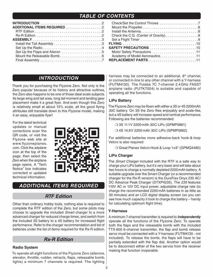
❏ 8. If you haven’t yet done so, replace the receiver back into the fuselage. (If assembling the Rx-R edition, mount the receiver in the fuselage with the included double-sided hook & loop material.)
Mount the Releasable Bomb
❏ 1. Mount the bomb mount with two M3 x 20 screws and the wire hook facing aft, while simultaneously inserting the top of the wire release hook into the outer hole of the bomb release servo arm (as shown in the image to the right).
Note: To release the bomb remotely, a 7-channel transmitter and receiver will be required. Or, the fl ap servo may be disconnected from the receiver, making a vacant channel available for the bomb release – of course, then the fl aps will be disabled. Or, the fl ap and bomb servos may be connected with a Y-harness (not included).
❏ 2. Connect the servo to an available channel in your receiver and use this channel to release the bomb.
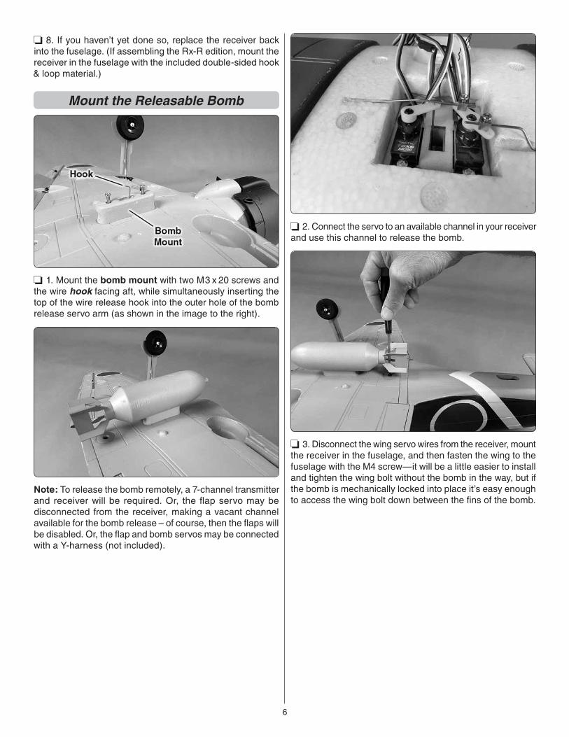
❏ 3. Disconnect the wing servo wires from the receiver, mount the receiver in the fuselage, and then fasten the wing to the fuselage with the M4 screw—it will be a little easier to install and tighten the wing bolt without the bomb in the way, but if the bomb is mechanically locked into place it’s easy enough to access the wing bolt down between the fi ns of the bomb.
7
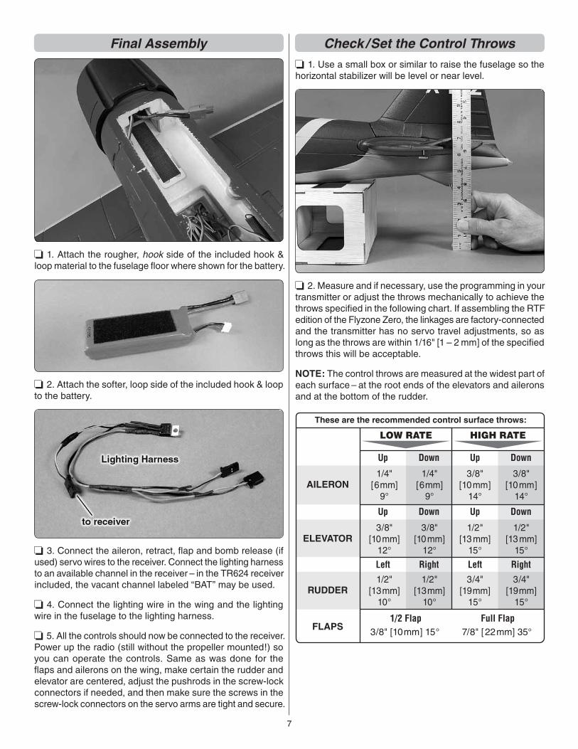
Final Assembly
❏ 1. Attach the rougher, hook side of the included hook & loop material to the fuselage fl oor where shown for the battery.
❏ 2. Attach the softer, loop side of the included hook & loop to the battery.
❏ 3. Connect the aileron, retract, fl ap and bomb release (if used) servo wires to the receiver. Connect the lighting harness to an available channel in the receiver – in the TR624 receiver included, the vacant channel labeled “BAT” may be used.
❏ 4. Connect the lighting wire in the wing and the lighting wire in the fuselage to the lighting harness.
❏ 5. All the controls should now be connected to the receiver. Power up the radio (still without the propeller mounted!) so you can operate the controls. Same as was done for the fl aps and ailerons on the wing, make certain the rudder and elevator are centered, adjust the pushrods in the screw-lock connectors if needed, and then make sure the screws in the screw-lock connectors on the servo arms are tight and secure.
Check /Set the Control Throws
❏ 1. Use a small box or similar to raise the fuselage so the horizontal stabilizer will be level or near level.
❏ 2. Measure and if necessary, use the programming in your transmitter or adjust the throws mechanically to achieve the throws specifi ed in the following chart. If assembling the RTF edition of the Flyzone Zero, the linkages are factory-connected and the transmitter has no servo travel adjustments, so as long as the throws are within 1/16" [1 – 2 mm] of the specifi ed throws this will be acceptable.
NOTE: The control throws are measured at the widest part of each surface – at the root ends of the elevators and ailerons and at the bottom of the rudder.
DownUp Up Down
3/8" [10mm] 15° FLAPS1/2 Flap
7/8" [22mm] 35° Full Flap
These are the recommended control surface throws:
1/4"[6mm]
9°
1/2"[13mm]
10°
3/8"[10mm]
12°
3/8"[10mm]
14°
3/4"[19mm]
15°
1/2"[13 mm]
15°
1/4"[6mm]
9°
1/2"[13mm]
10°
3/8"[10mm]
12°
3/8"[10mm]
14°
3/4"[19mm]
15°
1/2"[13 mm]
15°
AILERON
ELEVATOR
LOW RATE HIGH RATE
RUDDER
DownUp Up Down
RightLeft RightLeft
8
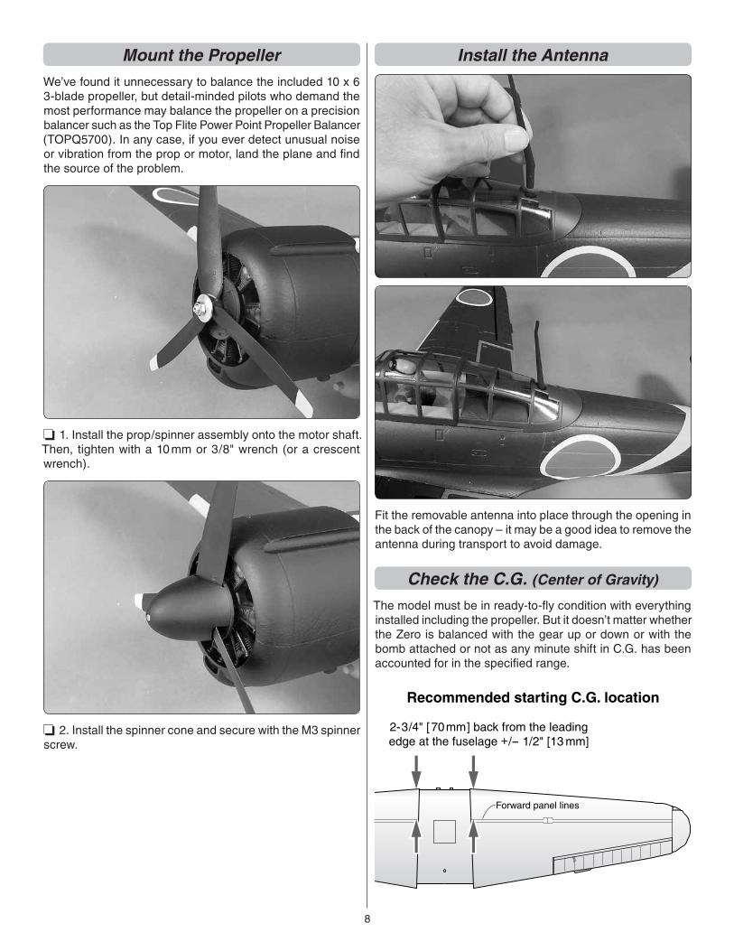
Mount the PropellerWe’ve found it unnecessary to balance the included 10 x 6 3-blade propeller, but detail-minded pilots who demand the most performance may balance the propeller on a precision balancer such as the Top Flite Power Point Propeller Balancer (TOPQ5700). In any case, if you ever detect unusual noise or vibration from the prop or motor, land the plane and fi nd the source of the problem.
❏ 1. Install the prop/spinner assembly onto the motor shaft. Then, tighten with a 10 mm or 3/8" wrench (or a crescent wrench).
❏ 2. Install the spinner cone and secure with the M3 spinner screw.
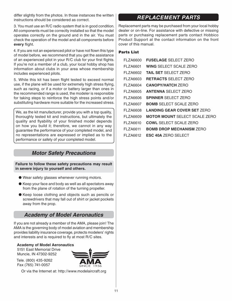
Install the Antenna
Fit the removable antenna into place through the opening in the back of the canopy – it may be a good idea to remove the antenna during transport to avoid damage.
Check the C.G. (Center of Gravity)
The model must be in ready-to-fl y condition with everything installed including the propeller. But it doesn’t matter whether the Zero is balanced with the gear up or down or with the bomb attached or not as any minute shift in C.G. has been accounted for in the specifi ed range.
Forward panel lines
2-3/4" [70mm] back from the leadingedge at the fuselage +/- 1/2" [13 mm]
Recommended starting C.G. location

9
❏ 1. Install the battery and canopy. Balance the model upside-down and support the wing on both sides of the fuselage at the starting, recommended C.G. location which is 2-3/4" [70mm] back from the leading edge of the wing – conveniently, this location is also at the forward panel line which you can feel with your fi ngertips when supporting the model.
❏ 2. If necessary, reposition the battery to get the model to balance. Once the correct battery location has been determined you could mark the location on the inside of the fuselage so you will know where to install it every time.
The full C.G. range is 2-1/4 in [57mm] – 3-1/4 in [83mm] back from the leading edge of the wing at the fuselage. You may shift the C.G. within the specifi ed range to change the fl ying characteristics to suit your taste – balanced farther back the Zero will become more maneuverable and less stable, but also fl oat longer on landing. Balanced nearer the front of the C.G. range the Zero will be more stable (less aerobatic), but also better suited to fl ying at higher speeds or windier conditions. Balancing the model outside the range could make the Zero diffi cult to fl y, possibly causing a crash. So always fl y your Zero within the specifi ed range.
Set a Flight TimerIt’s better to limit your fl ying time with a timer set to a pre- calculated time instead of waiting for the LVC (low voltage cutoff) in your ESC to kick in or until you notice a decrease in fl ight performance. By then, it may be too late to make more than one landing attempt.
Typical, average battery consumption with the Flyzone Zero is approximately 220 mAh/minute on 3S and approximately 320 mAh/minute on 4S. But your fl ying style, battery condition and weather conditions may cause these fi gures to vary, so until you know for sure, start by setting your timer conservatively to 6 or 4 minutes respectively. If your transmitter has a timer built in, link the timer to your throttle stick so only motor run time is counted. Fly until the timer sounds and land. Note the time on your transmitter and charge the battery. If your charger has a digital readout (indicating how much capacity it took to recharge which indicates how much capacity was used during the fl ight), divide the capacity that went back into your battery by the fl ight time to calculate your average battery consumption for that fl ight. Divide 80% of your battery capacity by that consumption rate to determine your new, target fl ight time.
Example:
Suppose you are using a 2200 mAh battery and after you landed, the motor run time on the timer was four minutes, fi fteen seconds (that’s 4.25 minutes in tenths). And say it took 1290 mAh to recharge your battery.
Divide 1290 mAh by 4.25 minutes to calculate an average battery consumption rate of about 300 mAh per minute.
Your limit capacity to use from a 2200 mAh battery is 1760 mAh (2200 mAh x 0.8), so 1760 mAh divided by 300 mAh/minute = 5.8 minutes (approximately 5 minutes, 45 seconds).
Maybe on your second fl ight set your timer to 5 minutes and repeat the procedure to continue to log data for calculating average target fl ight times.
The more data you log and the more calculations you do, the more accurate your calculated fl ight times will be – so you never have an unplanned dead-stick landing or over discharge your batteries.

10
Here’s a worksheet you can use for recording fl ight times and recharge capacity to calculate target fl ight times (as well as average, in-fl ight current which is also useful data). The second row contains formulas for the calculations for that row. Row #1 is already fi lled out with fi gures from the example:
FORMULASA
123456789
10
B C D E F GB / A D x .8 E / C B/1000 / (A/60)
Flight Time(.10 ths )
RechargeCapacity mAh/minute
BatteryCapacity
Target Capacityto Use in Flight
RecommendedFlight Time
Avg. In-FlightCurrent
start working. Otherwise, the Zero occasionally exhibits the tendency to nose down slightly during initial rollout. But once up to speed you can keep in the main wheels on the ground for a beautiful, scale-like rollout as long as you please!
There’s nothing particular to note about the Zero once airborne – on 3S it fl ies quite “scale-like,” and on 4S the Zero is signifi cantly faster with increased vertical performance.
Again alluding to the Zero’s scale-like fl ight tendencies, it does land a little better if you fl y it in with a little throttle–especially if landing with fl aps. Same as most warbirds, the Zero is somewhat of a draggy airframe and bleeds off speed a little faster than your typical sport plane. Just leave a few clicks of throttle in, wait for it to slow and you’ll see it fl airs or two-points beautifully.
You’ll fi nd that fl aps aren’t necessary if landing in breezy conditions. But if the weather is calm the fl aps will slow the Zero even more!
SAFETY PRECAUTIONS
Protect Your Model, Yourself & Others…Follow These Important Safety Precautions
1. Your Zero should not be considered a toy, but rather a sophisticated, working model that functions very much like a full-size airplane. Because of its performance capabilities, the Zero, if not assembled and operated correctly, could possibly cause injury to yourself or spectators and damage to property.
2. You must assemble the Zero according to the instructions. Do not alter or modify the model, as doing so may result in an unsafe or unfl yable model. In a few cases the instructions may
Additionally, or if you don’t have a charger with a digital readout to fi nd out how much capacity you used during a fl ight, use a LiPo cell checker to check individual cell voltage after each fl ight. The resting, non-loaded, individual cell voltage after a fl ight should be no less than 3.7 V/cell.
FLYINGThe Zero doesn’t exhibit any negative fl ight tendencies, but here are a couple of tips that will help you present your Zero better out at the fl ying fi eld.
Choose a suitable takeoff and landing surface of short grass or a smooth surface.
On the 4S battery the Zero is aerobatic and speedy, but it still likes to be treated like a scale model. During the initial few feet of the takeoff roll use up elevator to hold the tail on the ground until it gains a little speed and the surfaces
11
differ slightly from the photos. In those instances the written instructions should be considered as correct.
3. You must use an R/C radio system that is in good condition. All components must be correctly installed so that the model operates correctly on the ground and in the air. You must check the operation of the model and all components before every fl ight.
4. If you are not an experienced pilot or have not fl own this type of model before, we recommend that you get the assistance of an experienced pilot in your R/C club for your fi rst fl ights. If you’re not a member of a club, your local hobby shop has information about clubs in your area whose membership includes experienced pilots.
5. While this kit has been fl ight tested to exceed normal use, if the plane will be used for extremely high stress fl ying, such as racing, or if a motor or battery larger than ones in the recommended range is used, the modeler is responsible for taking steps to reinforce the high stress points and/or substituting hardware more suitable for the increased stress.
We, as the kit manufacturer, provide you with a top quality, thoroughly tested kit and instructions, but ultimately the quality and fl yability of your fi nished model depends on how you build it; therefore, we cannot in any way guarantee the performance of your completed model, and no representations are expressed or implied as to the performance or safety of your completed model.
Motor Safety Precautions
Failure to follow these safety precautions may result in severe injury to yourself and others.
● Wear safety glasses whenever running motors.
● Keep your face and body as well as all spectators away from the plane of rotation of the turning propeller.
● Keep loose clothing and objects such as pencils or screwdrivers that may fall out of shirt or jacket pockets away from the prop.
Academy of Model AeronauticsIf you are not already a member of the AMA, please join! The AMA is the governing body of model aviation and membership provides liability insurance coverage, protects modelers’ rights and interests and is required to fl y at most R/C sites.
Academy of Model Aeronautics5151 East Memorial DriveMuncie, IN 47302-9252
Tele. (800) 435-9262Fax (765) 741-0057
Or via the Internet at: http://www.modelaircraft.org
REPLACEMENT PARTSReplacement parts may be purchased from your local hobby dealer or on-line. For assistance with defective or missing parts or purchasing replacement parts contact Hobbico Product Support at the contact information on the front cover of this manual.
Parts List
FLZA6600 FUSELAGE SELECT ZERO
FLZA6601 WING SELECT SCALE ZERO
FLZA6602 TAIL SET SELECT ZERO
FLZA6603 RETRACTS SELECT ZERO
FLZA6604 CANOPY/HATCH ZERO
FLZA6605 ANTENNA SELECT ZERO
FLZA6606 SPINNER SELECT ZERO
FLZA6607 BOMB SELECT SCALE ZERO
FLZA6608 LANDING GEAR COVER SET ZERO
FLZA6609 MOTOR MOUNT SELECT SCALE ZERO
FLZA6610 COWL SELECT SCALE ZERO
FLZA6611 BOMB DROP MECHANISM ZERO
FLZA6612 ESC 40A ZERO SELECT

1212
®