instruction manual - the home depot · pdf fileinstruction manual v1.0 ... this user...
TRANSCRIPT

SN503-8CH 1
INSTRUCTION MANUAL V1.0SN503-8CHwww.defender-usa.com
8 Channel H.264 Smart LCD-DVR Security Camera
w/ Coaching iMenu and Night Vision Surveillance Cameras

SN503-8CHSN503-8CH
NEEDHELP?
DO NOT RETURN THIS PRODUCT TO THE STORE
Please contact a DEFENDER customer support representative first regarding any additional information on product features, specifications or assistance with setup.
Please contact us via one of the methods below:
Toll free telephone: 1.866.946.7828
For more product information visit www.defender-usa.com
Email: [email protected]
Online live web chat: Visit www.defender-usa.com
Toll free fax:1.888.771.1701
Note: This is manual version 1.0 for this product, you may find updated versions by visiting our website.
IMPORTANT! PLEASE READ!

TO REDUCE THE RISK OF ELECTRIC SHOCK, DO NOT REMOVE THE COVER (BACK).NO USER SERVICEABLE PARTS INSIDE. REFER SERVICING TO QUALIFIED SERVICE PERSONNEL.
CAUTIONRISK OF ELECTRIC SHOCK, DO NOT OPEN MONITOR
PRODUCT WARRANTY INFORMATION
Please visit our website at www.defender-usa.com for information about your product’s warranty.
We take quality very seriously. That is why all of our products come with a one year warranty from the original purchase date against defects in workmanship and materials. If you have warranty or support issues please contact us using any of the following methods: Phone: 1.866.946.7828 DEFENDER USA DEFENDER CANADAFax: 1.888.771.1701 60 Industrial Parkway #Z64 4080 Montrose Road Email: [email protected] Cheektowaga, NY Niagara Falls, ON Website: www.defender-usa.com USA 14227 Canada L2H 1J9
Warranty Terms
1. Defender products are guaranteed for a period of one year from the date of purchase against defects in workmanship and materials. This warranty is limited to the repair, replacement or refund of the purchase price at Defender’s option.2. This warranty becomes void if the product shows evidence of having been misused, mishandled or tampered with contrary to the applicable instruction manual. 3. Routine cleaning, normal cosmetic and mechanical wear and tear are not covered under the terms of this warranty. 4. The warranty expressly provided for herein is the sole warranty provided in connection with the product itself and no other warranty, expressed or implied is provided. Defender assumes no responsibilities for any other claims not specifically mentioned in this warranty. 5. This warranty does not cover shipping costs, insurance, or any other incidental charges. 6. You MUST call Defender before sending any product back for repair. You will be sent a Return Authorization number with return instructions. When returning the product for warranty service, please pack it carefully in the original box with all supplied accessories, and enclose your original receipt or copy, and a brief explanation of the problem (include RA #). 7. This warranty is valid only in Canada and the continental U.S.8. This warranty cannot be re-issued.
SN503-8CH
IMPORTANT! PLEASE READ!
SN503-8CH 1
TABLE OF CONTENTS .............................................................................................. 1
INTRODUCTION .................................................................................................... 3
WHAT IS INCLUDED ............................................................................................... 3
FEATURES ............................................................................................................ 4
OPTIONAL ACCESSORIES ........................................................................................ 5
BUTTONS AND CONNECTIONS ................................................................................. 6
BASIC SETUP ........................................................................................................ 8 Things to Consider Before Installation ........................................................................ 8 Mounting the Cameras ............................................................................................... 8 Connecting Peripheral Cable ....................................................................................... 9 Wiring Diagram for Cameras ....................................................................................... 9
CONNECTING ADDITIONAL DEVICES ....................................................................... 10 Connecting a USB Mouse .......................................................................................... 10 Connecting a Monitor ............................................................................................... 10 Connecting a PTZ Camera ......................................................................................... 10
POWERING ON DVR ............................................................................................. 11
GETTING STARTED ............................................................................................... 11 Using the Mouse ....................................................................................................... 11 Viewing Your Cameras .............................................................................................. 11
FUNCTION MENU ................................................................................................ 12 Function Menu Options ............................................................................................ 12
MAIN MENU ....................................................................................................... 15 Using the Keyboard .................................................................................................. 16 Camera Setup ........................................................................................................... 16 Privacy Zone ............................................................................................................. 18 Record Setup ............................................................................................................ 20 Network Setup Menu ................................................................................................ 22 Video Search ............................................................................................................. 25 Devices ..................................................................................................................... 27 HDD .......................................................................................................... 28 Alarm Setup.............................................................................................. 30 PTZ Setup ................................................................................................. 31 Mobile Setup ............................................................................................ 31 Motion Detection ...................................................................................... 32 System Setup ............................................................................................................ 34 Date and Time ........................................................................................... 34 Password Setup ........................................................................................ 37 Video Setup .............................................................................................. 38 Language ................................................................................................. 39 System Information .................................................................................. 39 Maintenance............................................................................................. 40
TABLE OF CONTENTS
SN503-8CH 2
TABLE OF CONTENTS
PLAYBACK .......................................................................................................... 41 Playback through DVR .............................................................................................. 41 Computer Playback ................................................................................................... 42 File Viewing.............................................................................................. 43 Software Functions .................................................................................. 44 Bottom Playback Functions ...................................................................... 45
NETWORK GUIDE ................................................................................................ 48 Requirements ........................................................................................................... 48 Connecting DVR to a Router ...................................................................................... 48 Finding your DVR’s IP Address ................................................................................... 49 Preparing your Computer for Viewing the DVR ......................................................... 49 Log in to the DVR ...................................................................................................... 52 Installing ActiveX Controls ........................................................................................ 52 Viewing DVR Outside Of your Network ..................................................................... 53 Option 1 ................................................................................................... 54 Option 2 .................................................................................................... 55 Testing Port Forwarding ........................................................................... 56 If You Cannot Connect ............................................................................... 57 DDNS Setup .............................................................................................................. 58 Logging into Software .............................................................................................. 61
ONLINE SOFTWARE ............................................................................................. 62 Live Mode ................................................................................................................. 63 PTZ Options .............................................................................................................. 64
PLAYBACK ......................................................................................................... 65
PLAYING BACK FOOTAGE ...................................................................................... 66
SETUP ............................................................................................................... 67
NETWORK SETUP MENU ....................................................................................... 70
MOBILE VIEWING ................................................................................................ 74
DVR TROUBLESHOOTING...................................................................................... 79
DVR SPECIFICATIONS ........................................................................................... 81
CAMERA MANUAL ............................................................................................... 83 What’s Included ........................................................................................................ 83 Features .................................................................................................................... 83 Wiring Diagram for Cameras ..................................................................................... 84 Drilling Template ...................................................................................................... 84 Camera Specifications ............................................................................................... 85 Camera Troubleshooting ........................................................................................... 86REPLACEMENT PARTS .......................................................................................... 87ADDITIONAL ACCESSORIES ................................................................................... 87
SN503-8CH 3
INTRODUCTION
WHAT IS INCLUDED
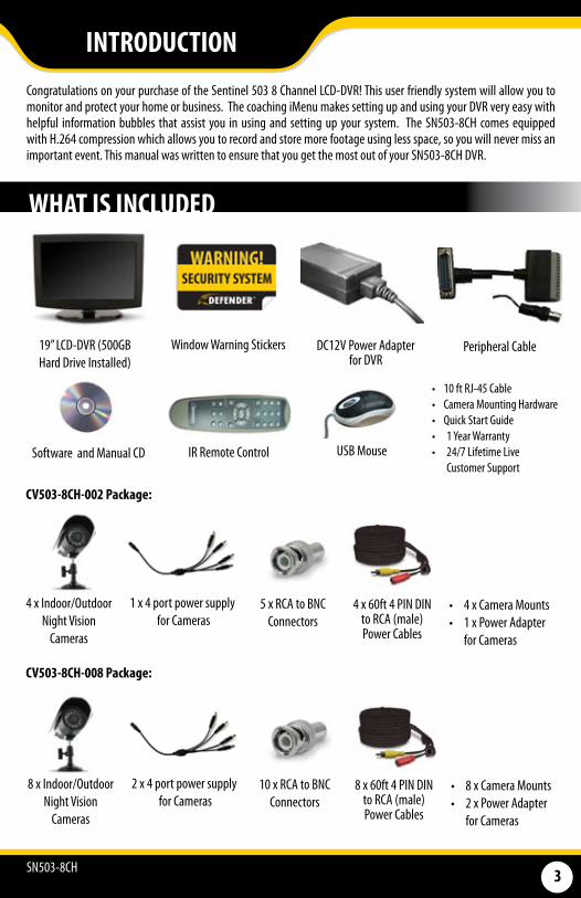
Congratulations on your purchase of the Sentinel 503 8 Channel LCD-DVR! This user friendly system will allow you to monitor and protect your home or business. The coaching iMenu makes setting up and using your DVR very easy with helpful information bubbles that assist you in using and setting up your system. The SN503-8CH comes equipped with H.264 compression which allows you to record and store more footage using less space, so you will never miss an important event. This manual was written to ensure that you get the most out of your SN503-8CH DVR.
• 10 ft RJ-45 Cable• Camera Mounting Hardware • Quick Start Guide • 1 Year Warranty • 24/7 Lifetime Live
Customer Support
19” LCD-DVR (500GB Hard Drive Installed)
DC12V Power Adapter for DVR
Peripheral Cable
4 x Indoor/Outdoor Night Vision
Cameras
Window Warning Stickers
4 x 60ft 4 PIN DIN to RCA (male)Power Cables
Software and Manual CD
1 x 4 port power supply for Cameras
5 x RCA to BNC Connectors
USB MouseIR Remote Control
• 4 x Camera Mounts• 1 x Power Adapter
for Cameras
CV503-8CH-002 Package:
CV503-8CH-008 Package:
8 x Indoor/Outdoor Night Vision
Cameras
8 x 60ft 4 PIN DIN to RCA (male)Power Cables
2 x 4 port power supply for Cameras
10 x RCA to BNC Connectors
• 8 x Camera Mounts• 2 x Power Adapter
for Cameras
SN503-8CH 4
FEATURES
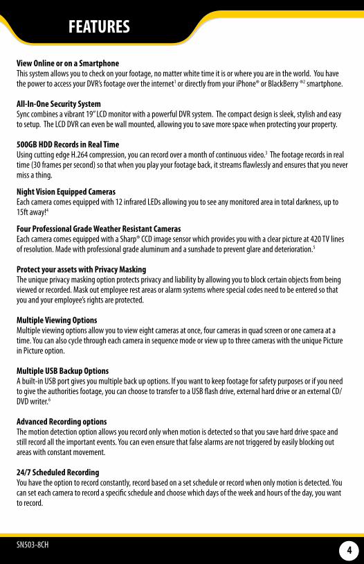
View Online or on a Smartphone This system allows you to check on your footage, no matter white time it is or where you are in the world. You have the power to access your DVR’s footage over the internet1 or directly from your iPhone® or BlackBerry ®2 smartphone.
All-In-One Security SystemSync combines a vibrant 19” LCD monitor with a powerful DVR system. The compact design is sleek, stylish and easy to setup. The LCD DVR can even be wall mounted, allowing you to save more space when protecting your property.
500GB HDD Records in Real Time Using cutting edge H.264 compression, you can record over a month of continuous video.3 The footage records in real time (30 frames per second) so that when you play your footage back, it streams flawlessly and ensures that you never miss a thing.
Night Vision Equipped Cameras Each camera comes equipped with 12 infrared LEDs allowing you to see any monitored area in total darkness, up to 15ft away!4
Four Professional Grade Weather Resistant Cameras Each camera comes equipped with a Sharp® CCD image sensor which provides you with a clear picture at 420 TV lines of resolution. Made with professional grade aluminum and a sunshade to prevent glare and deterioration.5
Protect your assets with Privacy MaskingThe unique privacy masking option protects privacy and liability by allowing you to block certain objects from being viewed or recorded. Mask out employee rest areas or alarm systems where special codes need to be entered so that you and your employee’s rights are protected.
Multiple Viewing OptionsMultiple viewing options allow you to view eight cameras at once, four cameras in quad screen or one camera at a time. You can also cycle through each camera in sequence mode or view up to three cameras with the unique Picture in Picture option.
Multiple USB Backup OptionsA built-in USB port gives you multiple back up options. If you want to keep footage for safety purposes or if you need to give the authorities footage, you can choose to transfer to a USB flash drive, external hard drive or an external CD/DVD writer.6
Advanced Recording optionsThe motion detection option allows you record only when motion is detected so that you save hard drive space and still record all the important events. You can even ensure that false alarms are not triggered by easily blocking out areas with constant movement.
24/7 Scheduled RecordingYou have the option to record constantly, record based on a set schedule or record when only motion is detected. You can set each camera to record a specific schedule and choose which days of the week and hours of the day, you want to record.
SN503-8CH 5
FEATURES
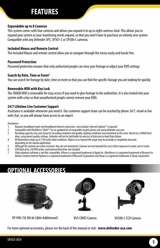
OPTIONAL ACCESSORIES
For more optional accessories, please see the back of the manual or visit: www.defender-usa.com
Expandable up to 8 CamerasThis system comes with four cameras and allows you expand it to up to eight cameras total. This allows you to expand your system as your monitoring needs expand, so that you won’t have to purchase an entirely new system. Compatible with any Defender SP5, SP301-C or SP500-C cameras.
Included Mouse and Remote ControlThe Included Mouse and remote control allow you to navigate through the menu easily and hassle free.
Password ProtectionPassword protection ensures that only authorized people can view your footage or adjust your DVR settings.
Search by Date, Time or Event7 You can search for footage by date, time or event so that you can find the specific footage you are looking for quickly.
Removable HDD with Key LockThe 500GB HDD is removable for easy access if you need to give footage to the authorities. It is also locked into your system with a key so that unauthorized people cannot remove your HDD.
24/7 Lifetime Live Customer SupportAssistance is available whenever you need it. Our customer support team can be reached by phone 24/7, email or live web chat, so you will always have access to an expert.
Disclaimers1. RequiresbroadbandrouterandbroadbandInternetconnection–notincluded.InternetExplorer®isrequired.2. CompatiblewithBlackBerry®Bold™.Foranupdatedlistofcompatiblemodelspleasevisitwww.defender-usa.com3. Recordingcapacitymayvarybasedonrecordingresolutionandquality,lightingconditionsandmovementinthescene.Basedona500GBhard
drive,usinglowestqualitysettings.DefenderwillnotbeheldliableforanylossofdataduetoHardDrivefailure.4. IRilluminationrangeupto15ftunderidealconditions.Objectsatorbeyondthisrangemaybepartiallyorcompletelyobscured,
dependingonthecameraapplication.5. Althoughthecamerasarewaterresistant,theyarenotwaterproof.Camerasarenotintendedforuseindirectexposuretowater,rainorsnow.6. USBflashdrive,CD/DVDwriter,andexternalharddrivenotincluded.7. VideoplaybacksoftwareisnotMaccompatible.iPhoneisaregisteredtrademarkofAppleInc.BlackBerryisaregisteredtrademarkofResearchin
MotionLimited,InternetExplorerisaregisteredtrademarkofMicrosoftCorporationandSharpisaregisteredtrademarkofSharpCorporation
DF10W (18.3M de Câble Additionnel) VU5 CMOS Camera VU500-C CCD Camera
SN503-8CH 6
BUTTON AND CONNECTIONS
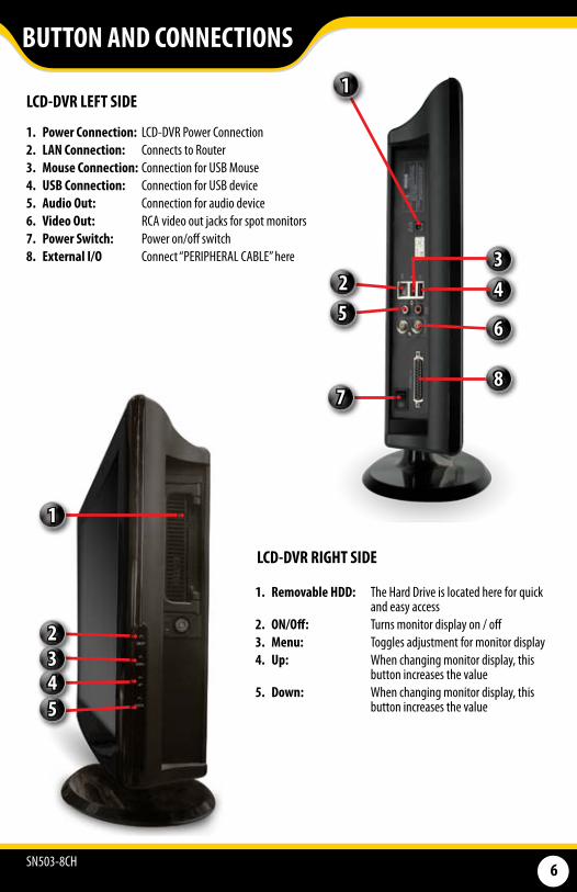
1. Power Connection: LCD-DVR Power Connection2. LAN Connection: Connects to Router3. Mouse Connection: Connection for USB Mouse 4. USB Connection: Connection for USB device5. Audio Out: Connection for audio device6. Video Out: RCA video out jacks for spot monitors7. Power Switch: Power on/off switch8. External I/O Connect “PERIPHERAL CABLE” here
LCD-DVR LEFT SIDE
1. Removable HDD: The Hard Drive is located here for quick and easy access
2. ON/Off: Turns monitor display on / off3. Menu: Toggles adjustment for monitor display4. Up: When changing monitor display, this
button increases the value5. Down: When changing monitor display, this
button increases the value
LCD-DVR RIGHT SIDE
1
2345
1
543
6
87
2
SN503-8CH 7
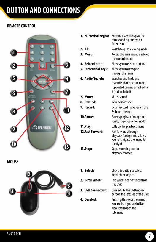
REMOTE CONTROL
MOUSE
BUTTON AND CONNECTIONS
1
3
4
7
11
12
13
2
5
6
8
9
10
1
2
34
1. Numerical Keypad: Buttons 1-8 will display the corresponding camera on full screen
2. All: Switch to quad viewing mode3. Menu: Access the main menu and exit
the current menu4. Select/Enter: Allows you to select options5. Directional Keys: Allows you to navigate
through the menu 6. Audio/Search: Searches and finds any
channels that have an audio supported camera attached to it (not included)
7. Mute: Mutes sound8. Rewind: Rewinds footage9. Record: Begins recording based on the
24 hour schedule10. Pause: Pauses playback footage and
starts/stops sequence mode11. Play: Calls up the playback menu12. Fast Forward: Fast forwards through
playback footage and allows you to navigate the menu to the right
13. Stop: Stops recording and/or playback footage
1. Select: Click this button to select highlighted object
2. Scroll Wheel: This wheel has no function on this DVR
3. USB Connection: Connects to the USB mouse port on the left side of the DVR
4. Deselect: Pressing this exits the menu you are in. If you are in live view it will open the sub menu
SN503-8CH 8
BASIC SETUP
THINGS TO CONSIDER BEFORE INSTALLATION• The camera should be installed between 8 to 13ft above the area to be monitored • Decide whether the camera will be wall mounted, ceiling mounted or sitting on a desk/table top. Before
mounting the camera, ensure there is nothing obstructing the camera’s view• Placing the camera in an open, visible area can help deter criminals • To cover large, dark areas such as backyards, garages and driveways, place cameras in locations such as the
roof or deck• Ensure that your camera is positioned away from light sources and that the sunshade is properly adjusted to
avoid glare • For best viewing results, the lighting in front of the camera should be about the same brightness as the
lighting around the area being monitored • Each camera comes with 60ft of video/power wire. If longer wiring distance is required, 60ft extensions can
be purchased (DF10W) from your local re-seller or at www.defender-usa.com • We recommend using a surge protected power bar to protect the camera’s internal circuitry
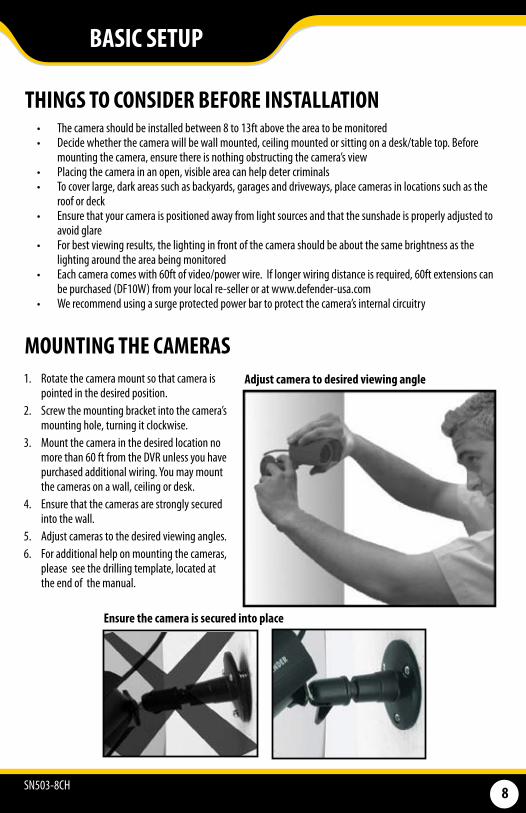
MOUNTING THE CAMERAS1. Rotate the camera mount so that camera is
pointed in the desired position. 2. Screw the mounting bracket into the camera’s
mounting hole, turning it clockwise. 3. Mount the camera in the desired location no
more than 60 ft from the DVR unless you have purchased additional wiring. You may mount the cameras on a wall, ceiling or desk.
4. Ensure that the cameras are strongly secured into the wall.
5. Adjust cameras to the desired viewing angles. 6. For additional help on mounting the cameras,
please see the drilling template, located at the end of the manual.
Adjust camera to desired viewing angle
Ensure the camera is secured into place
SN503-8CH 9
BASIC SETUP
AB C
D
HF
G
E
L J
K
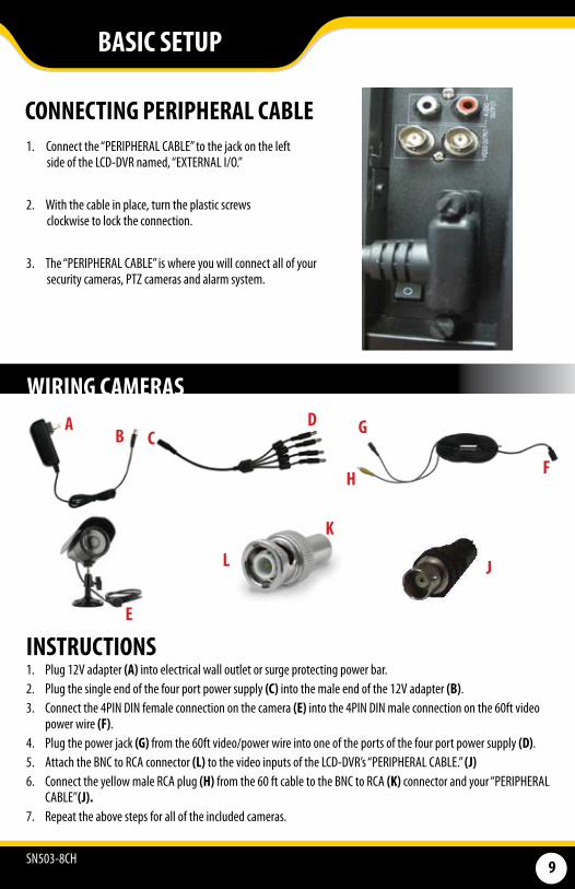
WIRING CAMERAS
CONNECTING PERIPHERAL CABLE1. Connect the “PERIPHERAL CABLE” to the jack on the left side of the LCD-DVR named, “EXTERNAL I/O.”
2. With the cable in place, turn the plastic screws clockwise to lock the connection.
3. The “PERIPHERAL CABLE” is where you will connect all of your security cameras, PTZ cameras and alarm system.
INSTRUCTIONS1. Plug 12V adapter (A) into electrical wall outlet or surge protecting power bar. 2. Plug the single end of the four port power supply (C) into the male end of the 12V adapter (B). 3. Connect the 4PIN DIN female connection on the camera (E) into the 4PIN DIN male connection on the 60ft video
power wire (F). 4. Plug the power jack (G) from the 60ft video/power wire into one of the ports of the four port power supply (D). 5. Attach the BNC to RCA connector (L) to the video inputs of the LCD-DVR’s “PERIPHERAL CABLE.” (J)6. Connect the yellow male RCA plug (H) from the 60 ft cable to the BNC to RCA (K) connector and your “PERIPHERAL
CABLE”(J).7. Repeat the above steps for all of the included cameras.
SN503-8CH 10
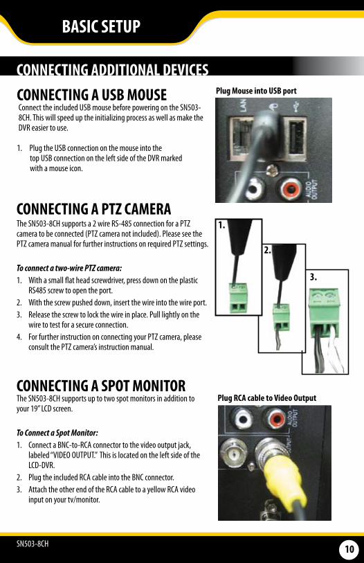
CONNECTING A USB MOUSE Connect the included USB mouse before powering on the SN503-8CH. This will speed up the initializing process as well as make the DVR easier to use.
1. Plug the USB connection on the mouse into the top USB connection on the left side of the DVR marked with a mouse icon.
CONNECTING ADDITIONAL DEVICESPlug Mouse into USB port
CONNECTING A PTZ CAMERAThe SN503-8CH supports a 2 wire RS-485 connection for a PTZ camera to be connected (PTZ camera not included). Please see the PTZ camera manual for further instructions on required PTZ settings.
To connect a two-wire PTZ camera: 1. With a small flat head screwdriver, press down on the plastic
RS485 screw to open the port.2. With the screw pushed down, insert the wire into the wire port. 3. Release the screw to lock the wire in place. Pull lightly on the
wire to test for a secure connection. 4. For further instruction on connecting your PTZ camera, please
consult the PTZ camera’s instruction manual.
1.
2.
3.
CONNECTING A SPOT MONITORThe SN503-8CH supports up to two spot monitors in addition to your 19” LCD screen.
To Connect a Spot Monitor:1. Connect a BNC-to-RCA connector to the video output jack,
labeled “VIDEO OUTPUT.” This is located on the left side of the LCD-DVR.
2. Plug the included RCA cable into the BNC connector.3. Attach the other end of the RCA cable to a yellow RCA video
input on your tv/monitor.
Plug RCA cable to Video Output
BASIC SETUP

SN503-8CH 11
USING THE MOUSEThe included USB mouse makes using the SN503-8CH quick and easy. The mouse functions just like a mouse for a computer - it allows you to click on items to select and change them. To get the most out of your SN503-8CH, we recommend using the mouse.
BASIC SETUP
GETTING STARTEDThe SN503-8CH is designed to be user friendly - you will notice the iMenu bubbles located toward the bottom of your screen which will describe your menu options.
SCREEN VIEWING By double clicking one of the eight camera screens, the viewing mode will switch to full screen mode. Double clicking again will bring you back to quad or eight screen mode (pending on what was set before).
Full Screen Quad Screen Eight Camera Screen
1. Insert the power cord into the power supply.2. Plug the power cord into a power outlet (surge
protected power outlet recommended).3. Insert the power supply wire into the DC 12V port on
the left side of the LCD-DVR.4. There is a power on/off switch located on the left side
of the SN503-8CH, press this down to turn on your security system. After a few moments, your DVR system will immediately begin recording!
Connect to a power source to turn on DVR
POWERING ON YOUR LCD-DVR
Note: Ensure that the mouse is connected to the designated USB port before powering on
SN503-8CH 12
FUNCTION MENU
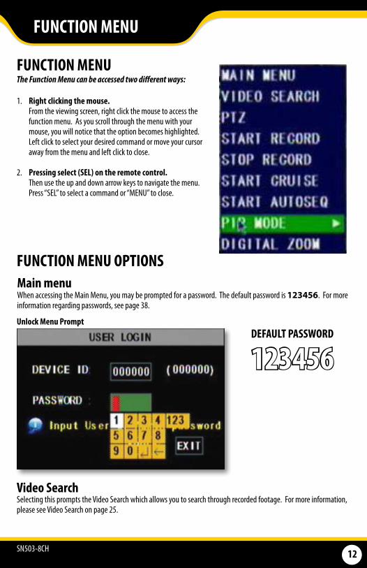
FUNCTION MENU The Function Menu can be accessed two different ways:
1. Right clicking the mouse. From the viewing screen, right click the mouse to access the
function menu. As you scroll through the menu with your mouse, you will notice that the option becomes highlighted. Left click to select your desired command or move your cursor away from the menu and left click to close.
2. Pressing select (SEL) on the remote control. Then use the up and down arrow keys to navigate the menu.
Press “SEL” to select a command or “MENU” to close.
FUNCTION MENU OPTIONSMain menu
DEFAULT PASSWORD
123456Unlock Menu Prompt
Video Search Selecting this prompts the Video Search which allows you to search through recorded footage. For more information, please see Video Search on page 25.
When accessing the Main Menu, you may be prompted for a password. The default password is 123456. For more information regarding passwords, see page 38.
SN503-8CH 13
SHORTCUT MENU
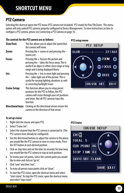
PTZ Camera
The controls for the PTZ camera are as follows: Slow/Fast: This bar allows you to adjust the speed that
the camera will move Zoom: Pressing the + zooms in and pressing the –
zooms out Focus: Pressing the + focuses the picture and
pressing the – takes the focus away. This is useful if an object is either close range or long range and is being displayed blurry
Iris: Pressing the + lets in more light and pressing the – takes light out of the picture. This is useful for varying lighting situations as well as correcting backlight issues
Cruise Setup: This function allows you to setup preset positions for the PTZ to follow, the PTZ camera will cruise through your set positions and times. Not all PTZ cameras have this function
Directional keys: Clicking on the directional arrows moves the camera in the direction of that arrow
To set up cruise: 1. Right click the mouse and open PTZ. 2. Select “Cruise Set”. 3. Select the channel that the PTZ camera is connected to. (The
PTZ camera must already be configured).4. Use the directional buttons to adjust the camera to the places
you would like the PTZ camera to view in cruise mode. Press the SET button at each desired position.
5. Click on stop time and set the time (in seconds) for how long you would like the PTZ camera to stay at each position.
6. To review your set points, select the current point you would like to view and click on “go to”.
7. Click “save” and then “exit”. 8. To erase all preset cruise points click on “clean.”9. To start the PTZ cruise, open the shortcut menu and select
“start cruise”. To stop the PTZ cruise, open the shortcut menu and select “stop cruise”.
Selecting this shortcut opens the PTZ menu (PTZ camera not included). PTZ stands for Pan/Tilt/Zoom. This menu option will only control PTZ cameras properly configured in Device Management. To view instructions on how to configure a PTZ camera, please see Connecting a PTZ Camera on page 10.
PTZ setup menu
PTZ Cruise
SN503-8CH 14
SHORTCUT MENU
Start Record • Selecting this prompts the LCD-DVR to begin manual recording (if it is not already recording). Selecting this
will override any set recording schedule
Stop Record • Selecting this prompts the LCD-DVR to stop manual recording
Start Cruise • Selecting this option prompts the PTZ cruise to start (if you have configured a compatible PTZ camera).
Selecting the cruise option again will stop the PTZ cruise
Start Auto Sequencing • Selecting this option prompts the cameras to sequence through each camera displayed on full screen. This
function will only work if you have more than one camera connected. Double click the screen to stop the automatic sequencing. For more information, please see Camera Sequence on page 19
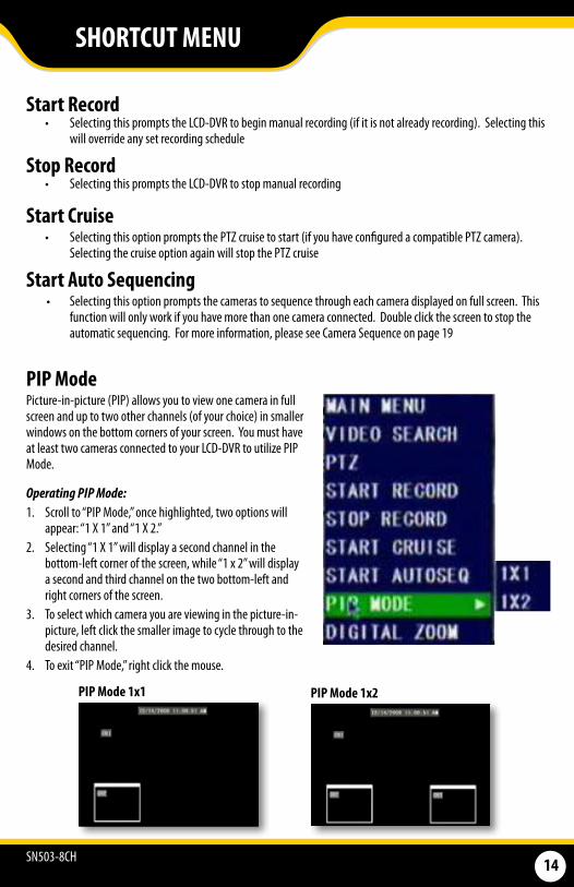
PIP ModePicture-in-picture (PIP) allows you to view one camera in full screen and up to two other channels (of your choice) in smaller windows on the bottom corners of your screen. You must have at least two cameras connected to your LCD-DVR to utilize PIP Mode.
Operating PIP Mode:1. Scroll to “PIP Mode,” once highlighted, two options will
appear: “1 X 1” and “1 X 2.”2. Selecting “1 X 1” will display a second channel in the
bottom-left corner of the screen, while “1 x 2” will display a second and third channel on the two bottom-left and right corners of the screen.
3. To select which camera you are viewing in the picture-in-picture, left click the smaller image to cycle through to the desired channel.
4. To exit “PIP Mode,” right click the mouse.
PIP Mode 1x1 PIP Mode 1x2
SN503-8CH 15
The main menu can be accessed by selecting it from the function menu or by pressing the “MENU” button on the remote control. While navigating the main menu, left click to select and right click to exit. The iMenu will inform you of the details for each option.
Many of the Submenus will Feature the Following Common Options:
1. DEFAULT: This option will restore all settings, on the current screen, to the default settings
2. APPLY: This option will confirm and save all of the adjustments made from this screen
3. EXIT: This button will exit the current screen without saving the adjustments
Note: All sub menus have some or all of the above options.
Main Menu
MAIN MENU
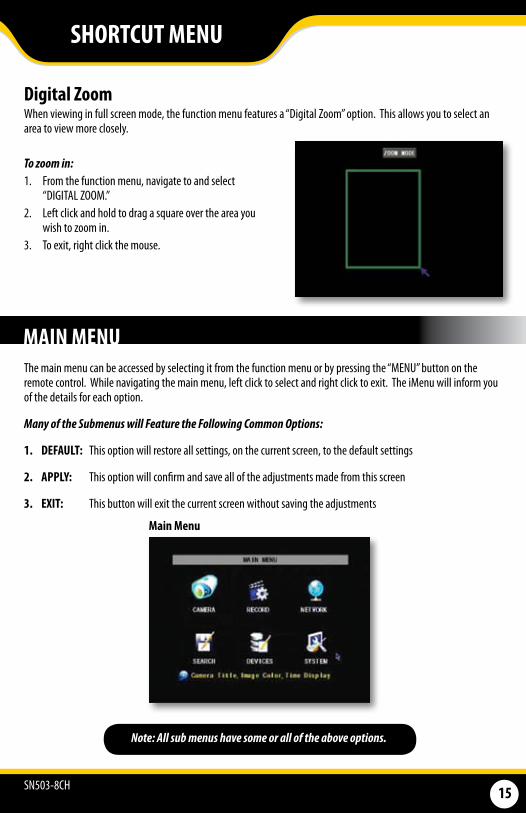
Digital Zoom When viewing in full screen mode, the function menu features a “Digital Zoom” option. This allows you to select an area to view more closely.
To zoom in: 1. From the function menu, navigate to and select
“DIGITAL ZOOM.”2. Left click and hold to drag a square over the area you
wish to zoom in.3. To exit, right click the mouse.
SHORTCUT MENU
SN503-8CH 16
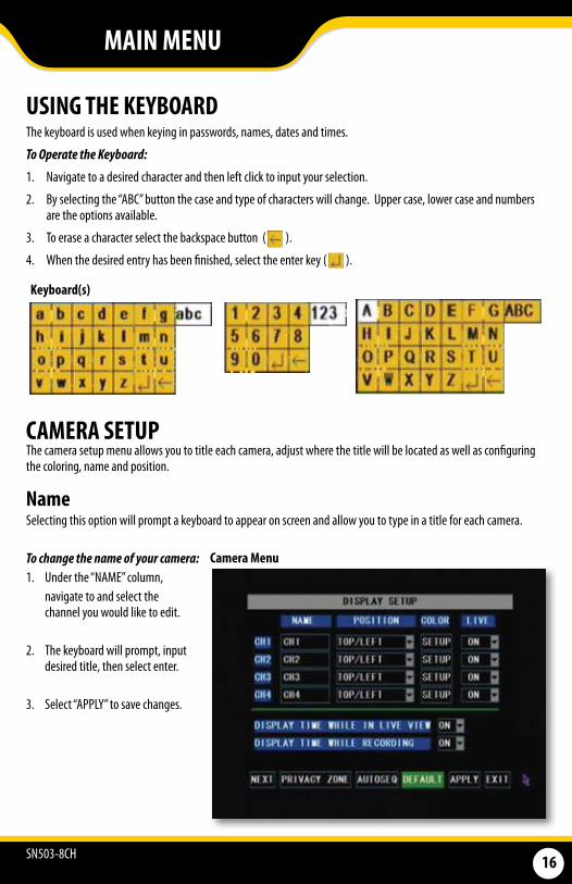
USING THE KEYBOARDThe keyboard is used when keying in passwords, names, dates and times.
To Operate the Keyboard:
1. Navigate to a desired character and then left click to input your selection.
2. By selecting the “ABC” button the case and type of characters will change. Upper case, lower case and numbers are the options available.
3. To erase a character select the backspace button ( ).
4. When the desired entry has been finished, select the enter key ( ).
Keyboard(s)
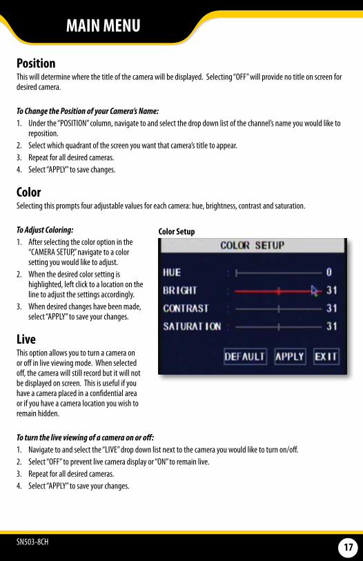
CAMERA SETUP The camera setup menu allows you to title each camera, adjust where the title will be located as well as configuring the coloring, name and position.
NameSelecting this option will prompt a keyboard to appear on screen and allow you to type in a title for each camera.
To change the name of your camera: 1. Under the “NAME” column, navigate to and select the
channel you would like to edit.
2. The keyboard will prompt, input desired title, then select enter.
3. Select “APPLY” to save changes.
Camera Menu
MAIN MENU
SN503-8CH 17
PositionThis will determine where the title of the camera will be displayed. Selecting “OFF” will provide no title on screen for desired camera.
To Change the Position of your Camera’s Name:1. Under the “POSITION” column, navigate to and select the drop down list of the channel’s name you would like to
reposition.2. Select which quadrant of the screen you want that camera’s title to appear.3. Repeat for all desired cameras. 4. Select “APPLY” to save changes.
ColorSelecting this prompts four adjustable values for each camera: hue, brightness, contrast and saturation.
To Adjust Coloring:1. After selecting the color option in the
“CAMERA SETUP,” navigate to a color setting you would like to adjust.
2. When the desired color setting is highlighted, left click to a location on the line to adjust the settings accordingly.
3. When desired changes have been made, select “APPLY” to save your changes.
LiveThis option allows you to turn a camera on or off in live viewing mode. When selected off, the camera will still record but it will not be displayed on screen. This is useful if you have a camera placed in a confidential area or if you have a camera location you wish to remain hidden.
To turn the live viewing of a camera on or off: 1. Navigate to and select the “LIVE” drop down list next to the camera you would like to turn on/off.2. Select “OFF” to prevent live camera display or “ON” to remain live.3. Repeat for all desired cameras.4. Select “APPLY” to save your changes.
Color Setup
MAIN MENU

SN503-8CH 18
Time DisplayThe SN503-8CH allows you to select if you would like the time and date displayed while in live view or while recording.
To Enable/Disable the Time Display:1. Select the drop down list next to the time display mode you would like to change. 2. Select “OFF” or “ON.”3. Select “APPLY” to save your settings.
Time Display Options
Privacy Zone“PRIVACY ZONE” allows you to set up to four adjustable areas per camera that you wish to mask or remain private. When enabled, the desired private location(s) will appear black on the viewing screen.
To Setup Privacy Zone:1. Select “PRIVACY ZONE” from the Camera Setup menu.2. Navigate to the desired channel, then, from the “PRIVACY
ZONE” drop down list, select the option from “OFF” to “ON.”3. There will be four check boxes titled “AREA” 1 through 4.
Choose how many individual privacy zones you would like to have by selecting the corresponding check box.
4. When the desired amount of privacy zones have been chosen, select “SETUP” to configure the location and size of each zone.
5. Left click, hold and drag the green privacy zone box over the desired area you would like to be made private.
6. To adjust the size of the privacy zone, navigate to the green border of the privacy zone, then left click, hold and drag the box to desired size.
7. When the privacy zones have been set, right click to exit.8. Select “APPLY” to save settings, then “EXIT” to close
Privacy Zone Setup
Screenshot
MAIN MENU
SN503-8CH 19
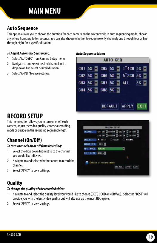
Auto SequenceThis option allows you to choose the duration for each camera on the screen while in auto sequencing mode; choose anywhere from zero to ten seconds. You can also choose whether to sequence only channels one through four or five through eight for a specific duration.
To Adjust Automatic Sequencing:1. Select “AUTOSEQ” from Camera Setup menu.2. Navigate to and select desired channel and a
drop down list, select desired duration.3. Select “APPLY” to save settings.
Auto Sequence Menu
RECORD SETUP This menu option allows you to turn on or off each camera, adjust the video quality, choose a recording mode or decide on the recording segment length.
Channel (On/Off)To turn channels on or off from recording: 1. Select the drop down list next to to the channel
you would like adjusted. 2. Navigate to and select whether or not to record the
channel. 3. Select “APPLY” to save settings.
QualityTo change the quality of the recorded video: 1. Navigate to and select the quality level you would like to choose (BEST, GOOD or NORMAL). Selecting “BEST” will
provide you with the best video quality but will also use up the most HDD space. 2. Select “APPLY” to save settings.
MAIN MENU
SN503-8CH 20
Note: Higher quality and resolution settings use up more space on your hard drive.
Audio Rec. To turn audio recording On or Off: 1. Navigate to and select the drop down menu beside “Audio Rec”. 2. Select which camera you would like the audio to record from and press select. 3. Select “APPLY” to save settings.
Rec. ModeThe SN503-8CH allows you to select if you want continuous recording or to record on a set schedule.
To program your LCD-DVR to always record: 1. Select the drop down list next to “REC. MODE.” 2. Navigate to and select “ALWAYS.” 3. Select “APPLY” to save settings.
To set your LCD-DVR for schedule record: 1. Select the drop down list next to “REC. MODE.”2. Navigate to and select “TIME SCHEDULE RECORD.” 3. Select “APPLY” to save settings.
Note: The default schedule is set to record on a 24/7 schedule
Note: Only audio enabled cameras (sold seperately) are able to record audio.
File SizeThe DVR allows you choose the maximum length that each recorded video clip will be. This is for backup purposes.
To adjust and/or set a file size: 1. Select the drop down menu beside “File size”. 2. Highlight the time you would like each recorded video clip to be (15, 30, 45 or 60 min) and press select. 3. Select “APPLY” to save settings.
MAIN MENU
SN503-8CH 21
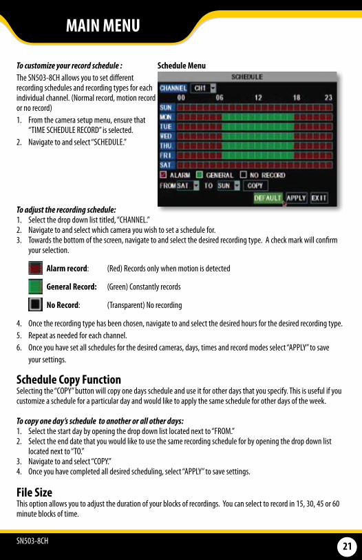
To customize your record schedule :The SN503-8CH allows you to set different recording schedules and recording types for each individual channel. (Normal record, motion record or no record) 1. From the camera setup menu, ensure that
“TIME SCHEDULE RECORD” is selected. 2. Navigate to and select “SCHEDULE.”
To adjust the recording schedule:1. Select the drop down list titled, “CHANNEL.” 2. Navigate to and select which camera you wish to set a schedule for. 3. Towards the bottom of the screen, navigate to and select the desired recording type. A check mark will confirm
your selection.
Alarm record: (Red) Records only when motion is detected
General Record: (Green) Constantly records
No Record: (Transparent) No recording
4. Once the recording type has been chosen, navigate to and select the desired hours for the desired recording type.5. Repeat as needed for each channel. 6. Once you have set all schedules for the desired cameras, days, times and record modes select “APPLY” to save your settings.
Schedule Menu
Schedule Copy FunctionSelecting the “COPY” button will copy one days schedule and use it for other days that you specify. This is useful if you customize a schedule for a particular day and would like to apply the same schedule for other days of the week.
To copy one day’s schedule to another or all other days: 1. Select the start day by opening the drop down list located next to “FROM.” 2. Select the end date that you would like to use the same recording schedule for by opening the drop down list
located next to “TO.”3. Navigate to and select “COPY.” 4. Once you have completed all desired scheduling, select “APPLY” to save settings.
File Size This option allows you to adjust the duration of your blocks of recordings. You can select to record in 15, 30, 45 or 60 minute blocks of time.
MAIN MENU
SN503-8CH 22
MAIN MENU
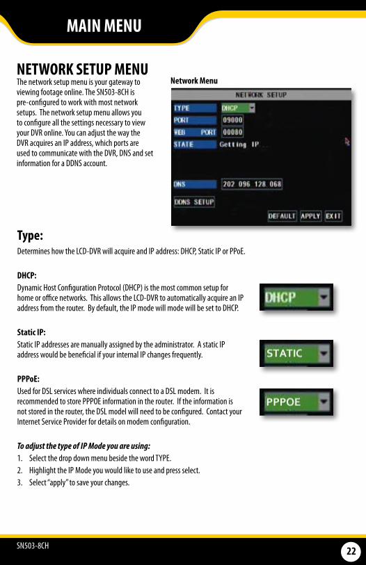
NETWORK SETUP MENUThe network setup menu is your gateway to viewing footage online. The SN503-8CH is pre-configured to work with most network setups. The network setup menu allows you to configure all the settings necessary to view your DVR online. You can adjust the way the DVR acquires an IP address, which ports are used to communicate with the DVR, DNS and set information for a DDNS account.
Network Menu
Type:Determines how the LCD-DVR will acquire and IP address: DHCP, Static IP or PPoE.
DHCP: Dynamic Host Configuration Protocol (DHCP) is the most common setup for home or office networks. This allows the LCD-DVR to automatically acquire an IP address from the router. By default, the IP mode will mode will be set to DHCP.
Static IP: Static IP addresses are manually assigned by the administrator. A static IP address would be beneficial if your internal IP changes frequently.
PPPoE: Used for DSL services where individuals connect to a DSL modem. It is recommended to store PPPOE information in the router. If the information is not stored in the router, the DSL model will need to be configured. Contact your Internet Service Provider for details on modem configuration.
To adjust the type of IP Mode you are using: 1. Select the drop down menu beside the word TYPE. 2. Highlight the IP Mode you would like to use and press select. 3. Select “apply” to save your changes.
SN503-8CH 23
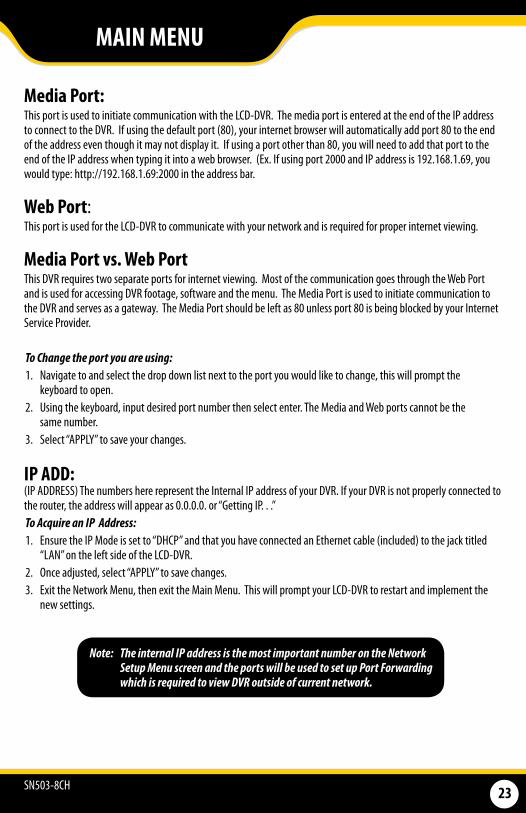
Media Port:This port is used to initiate communication with the LCD-DVR. The media port is entered at the end of the IP address to connect to the DVR. If using the default port (80), your internet browser will automatically add port 80 to the end of the address even though it may not display it. If using a port other than 80, you will need to add that port to the end of the IP address when typing it into a web browser. (Ex. If using port 2000 and IP address is 192.168.1.69, you would type: http://192.168.1.69:2000 in the address bar.
Web Port: This port is used for the LCD-DVR to communicate with your network and is required for proper internet viewing.
Media Port vs. Web PortThis DVR requires two separate ports for internet viewing. Most of the communication goes through the Web Port and is used for accessing DVR footage, software and the menu. The Media Port is used to initiate communication to the DVR and serves as a gateway. The Media Port should be left as 80 unless port 80 is being blocked by your Internet Service Provider.
To Change the port you are using:1. Navigate to and select the drop down list next to the port you would like to change, this will prompt the
keyboard to open.2. Using the keyboard, input desired port number then select enter. The Media and Web ports cannot be the
same number.3. Select “APPLY” to save your changes.
IP ADD: (IP ADDRESS) The numbers here represent the Internal IP address of your DVR. If your DVR is not properly connected to the router, the address will appear as 0.0.0.0. or “Getting IP. . .” To Acquire an IP Address:1. Ensure the IP Mode is set to “DHCP” and that you have connected an Ethernet cable (included) to the jack titled
“LAN” on the left side of the LCD-DVR.2. Once adjusted, select “APPLY” to save changes.3. Exit the Network Menu, then exit the Main Menu. This will prompt your LCD-DVR to restart and implement the
new settings.
Note: The internal IP address is the most important number on the Network Setup Menu screen and the ports will be used to set up Port Forwarding which is required to view DVR outside of current network.
MAIN MENU
SN503-8CH 24
DNS: Domain Name System (DNS) is for advanced network setup. DNS is used to convert names into IP addresses. It is recommended to leave these settings as they will be automatically configured by the router.
To adjust the DNS address:1. Navigate to the DNS address bar, select it to adjust the value.2. The keyboard will prompt, input the desired address then select the enter key.
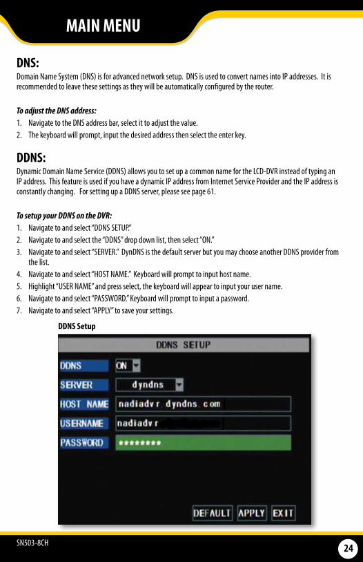
DDNS: Dynamic Domain Name Service (DDNS) allows you to set up a common name for the LCD-DVR instead of typing an IP address. This feature is used if you have a dynamic IP address from Internet Service Provider and the IP address is constantly changing. For setting up a DDNS server, please see page 61.
To setup your DDNS on the DVR:1. Navigate to and select “DDNS SETUP.” 2. Navigate to and select the “DDNS” drop down list, then select “ON.” 3. Navigate to and select “SERVER.” DynDNS is the default server but you may choose another DDNS provider from
the list. 4. Navigate to and select “HOST NAME.” Keyboard will prompt to input host name. 5. Highlight “USER NAME” and press select, the keyboard will appear to input your user name.6. Navigate to and select “PASSWORD.” Keyboard will prompt to input a password. 7. Navigate to and select “APPLY” to save your settings.
DDNS Setup
MAIN MENU
SN503-8CH 25
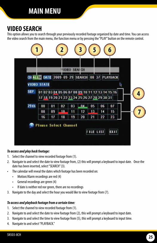
VIDEO SEARCH This option allows you to search through your previously recorded footage organized by date and time. You can access the video search from the main menu, the function menu or by pressing the “PLAY” button on the remote control.
To access and play back footage: 1. Select the channel to view recorded footage from (1). 2. Navigate to and select the date to view footage from, (2) this will prompt a keyboard to input date. Once the
date has been inserted, select “SEARCH” (3).• The calendar will reveal the dates which footage has been recorded on:
• Motion/Alarm recordings are red (4)• General recordings are green (4)• If date is neither red nor green, there are no recordings
3. Navigate to the day and select the hour you would like to view footage from (7).
To access and playback footage from a certain time:1. Select the channel to view recorded footage from (1). 2. Navigate to and select the date to view footage from (2), this will prompt a keyboard to input date.3. Navigate to and select the time to view footage from (5), this will prompt a keyboard to input time.4. Navigate to and select “PLAYBACK.”
MAIN MENU
SN503-8CH 26
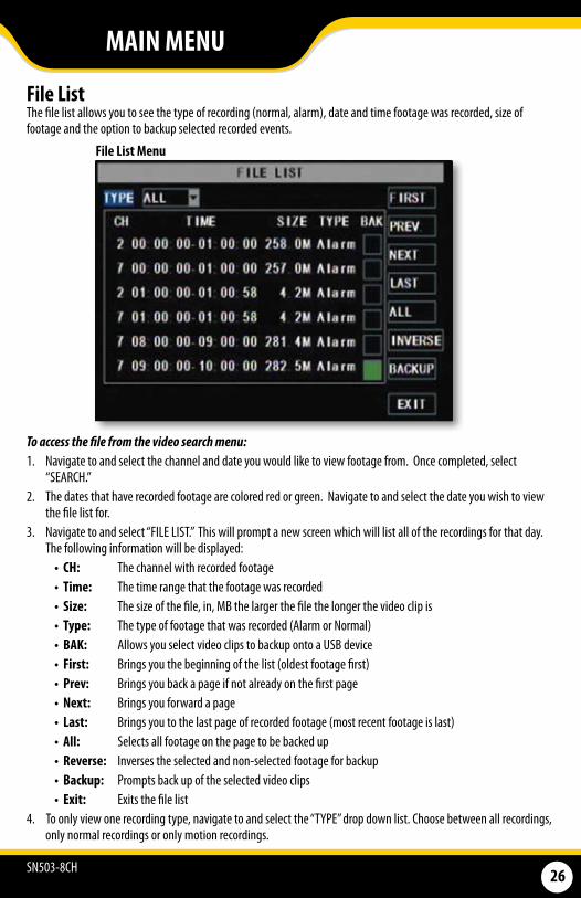
File List The file list allows you to see the type of recording (normal, alarm), date and time footage was recorded, size of footage and the option to backup selected recorded events.
To access the file from the video search menu:1. Navigate to and select the channel and date you would like to view footage from. Once completed, select
“SEARCH.” 2. The dates that have recorded footage are colored red or green. Navigate to and select the date you wish to view
the file list for. 3. Navigate to and select “FILE LIST.” This will prompt a new screen which will list all of the recordings for that day.
The following information will be displayed:• CH: The channel with recorded footage• Time: The time range that the footage was recorded • Size: The size of the file, in, MB the larger the file the longer the video clip is• Type: The type of footage that was recorded (Alarm or Normal) • BAK: Allows you select video clips to backup onto a USB device • First: Brings you the beginning of the list (oldest footage first)• Prev: Brings you back a page if not already on the first page • Next: Brings you forward a page • Last: Brings you to the last page of recorded footage (most recent footage is last)• All: Selects all footage on the page to be backed up • Reverse: Inverses the selected and non-selected footage for backup• Backup: Prompts back up of the selected video clips• Exit: Exits the file list
4. To only view one recording type, navigate to and select the “TYPE” drop down list. Choose between all recordings, only normal recordings or only motion recordings.
File List Menu
MAIN MENU
SN503-8CH 27
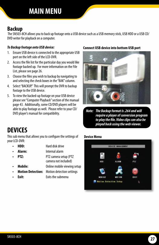
To Backup footage onto USB device: 1. Ensure USB device is connected to the appropriate USB
port on the left side of the LCD-DVR.2. Access the file list for the particular day you would like
footage backed up. For more information on the File List, please see page 26.
3. Choose the files you wish to backup by navigating to and selecting the check boxes in the “BAK” column.
4. Select “BACKUP.” This will prompt the DVR to backup footage to the USB device.
5. To view the backed-up footage on your USB device please see “Computer Playback” section of the manual page 43. Additionally, some CD/DVD players will be able to play footage as well. Please refer to your CD/DVD player’s manual for compatibility.
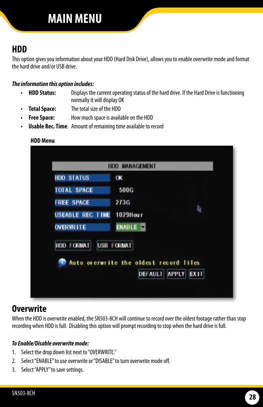
DEVICESThis sub menu that allows you to configure the settings of your LCD-DVR:
• HDD: Hard disk drive • Alarm: Internal alarm • PTZ: PTZ camera setup (PTZ
camera not included)• Mobile: Online mobile viewing setup• Motion Detection: Motion detection settings• Exit: Exits the submenu
Device Menu
BackupThe SN503-8CH allows you to back up footage onto a USB device such as a USB memory stick, USB HDD or a USB CD/DVD writer for playback on a computer.
Connect USB device into bottom USB port
Note: The Backup format is .264 and will require a player of conversion program to play the file. Video clips can also be played back using the web viewer.
MAIN MENU
SN503-8CH 28
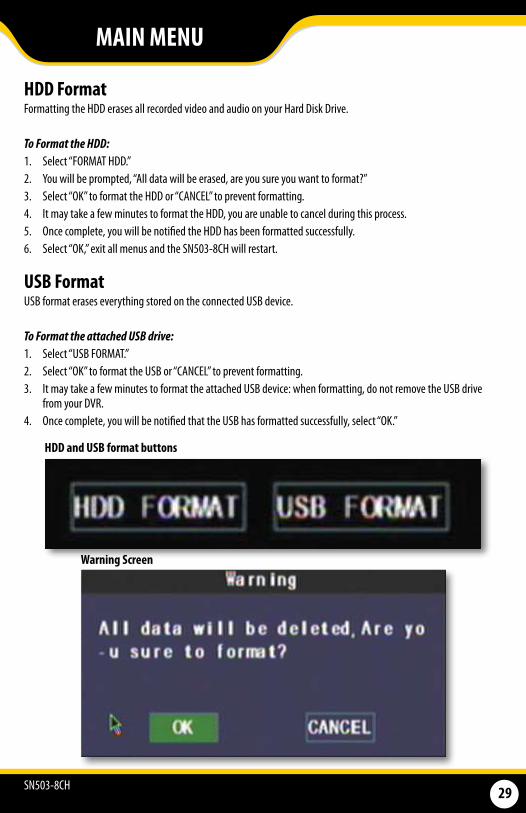
HDD This option gives you information about your HDD (Hard Disk Drive), allows you to enable overwrite mode and format the hard drive and/or USB drive.
The information this option includes:• HDD Status: Displays the current operating status of the hard drive. If the Hard Drive is functioning
normally it will display OK • Total Space: The total size of the HDD• Free Space: How much space is available on the HDD • Usable Rec. Time: Amount of remaining time available to record
HDD Menu
OverwriteWhen the HDD is overwrite enabled, the SN503-8CH will continue to record over the oldest footage rather than stop recording when HDD is full. Disabling this option will prompt recording to stop when the hard drive is full.
To Enable/Disable overwrite mode: 1. Select the drop down list next to “OVERWRITE.”2. Select “ENABLE” to use overwrite or “DISABLE” to turn overwrite mode off.3. Select “APPLY” to save settings.
MAIN MENU
SN503-8CH 29
HDD Format Formatting the HDD erases all recorded video and audio on your Hard Disk Drive.
To Format the HDD: 1. Select “FORMAT HDD.” 2. You will be prompted, “All data will be erased, are you sure you want to format?”3. Select “OK” to format the HDD or “CANCEL” to prevent formatting. 4. It may take a few minutes to format the HDD, you are unable to cancel during this process. 5. Once complete, you will be notified the HDD has been formatted successfully. 6. Select “OK,” exit all menus and the SN503-8CH will restart.
USB Format USB format erases everything stored on the connected USB device.
To Format the attached USB drive:1. Select “USB FORMAT.” 2. Select “OK” to format the USB or “CANCEL” to prevent formatting. 3. It may take a few minutes to format the attached USB device: when formatting, do not remove the USB drive
from your DVR. 4. Once complete, you will be notified that the USB has formatted successfully, select “OK.”
HDD and USB format buttons
Warning Screen
MAIN MENU
SN503-8CH 30
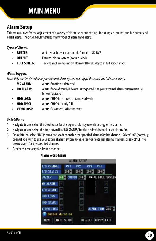
Alarm Setup This menu allows for the adjustment of a variety of alarm types and settings including an internal audible buzzer and email alerts. The SN503-8CH features many types of alarms and alerts.
Types of Alarms:• BUZZER: An internal buzzer that sounds from the LCD-DVR• OUTPUT: External alarm system (not included)• FULL SCREEN: The channel prompting an alarm will be displayed in full screen mode
Alarm Triggers:Note:Onlymotiondetectionoryourexternalalarmsystemcantriggertheemailandfullscreenalerts.
• MD ALARM: Alerts if motion is detected• I/O ALARM: Alerts if one of your I/O devices is triggered (see your external alarm system manual
for configuration)• HDD LOSS: Alerts if HDD is removed or tampered with • HDD SPACE: Alerts if HDD is nearly full• VIDEO LOSS: Alerts if a camera is disconnected
To Set Alarms:1. Navigate to and select the checkboxes for the types of alerts you wish to trigger the alarms.2. Navigate to and select the drop down list, “I/O STATUS,” for the desired channel to set alarms for.3. From this list, select “NC” (normally closed) to enable the specified alarms for that channel. Select “NO” (normally
open) if you wish to use your external alarm system (please see your external alarm’s manual) or select “OFF” to use no alarm for the specified channel.
4. Repeat as necessary for desired channels.
Alarm Setup Menu
MAIN MENU
SN503-8CH 31
PTZ SetupPTZ setup allows you to input information for a PTZ camera (PTZ camera not included).
To input the PTZ information:NOTE:RefertoyourPTZcamera’smanualfordetailedinstructionsoninstallationandconfigurationsettings.1. Input designated information of your PTZ cameras for the appropriate channels. 2. From this menu you can also choose to enable/disable cruise mode for the PTZ camera. 3. When all PTZ related information is entered, select “APPLY” to save changes.
MAIN MENU
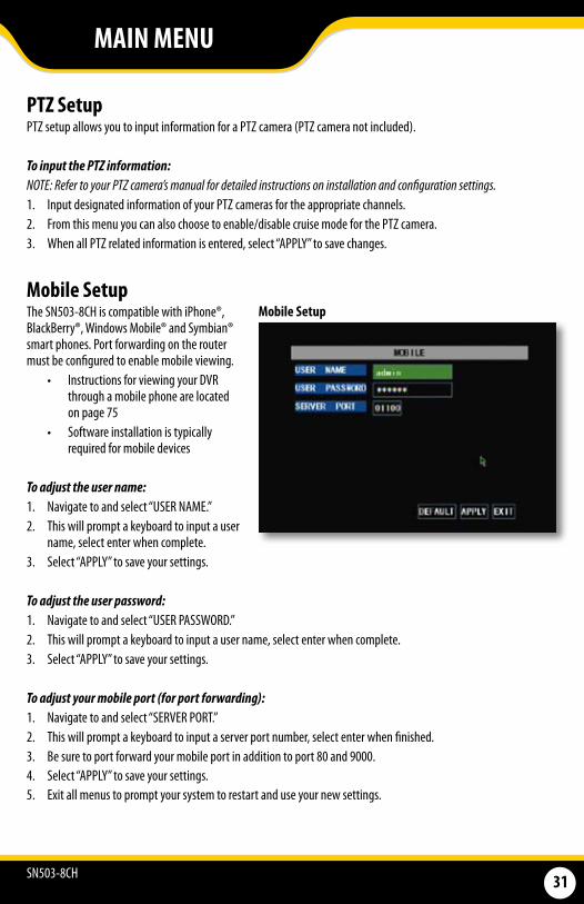
Mobile SetupThe SN503-8CH is compatible with iPhone®, BlackBerry®, Windows Mobile® and Symbian® smart phones. Port forwarding on the router must be configured to enable mobile viewing.
• Instructions for viewing your DVR through a mobile phone are located on page 75
• Software installation is typically required for mobile devices
To adjust the user name:1. Navigate to and select “USER NAME.”2. This will prompt a keyboard to input a user
name, select enter when complete.3. Select “APPLY” to save your settings.
To adjust the user password:1. Navigate to and select “USER PASSWORD.”2. This will prompt a keyboard to input a user name, select enter when complete.3. Select “APPLY” to save your settings.
To adjust your mobile port (for port forwarding):1. Navigate to and select “SERVER PORT.”2. This will prompt a keyboard to input a server port number, select enter when finished.3. Be sure to port forward your mobile port in addition to port 80 and 9000.4. Select “APPLY” to save your settings.5. Exit all menus to prompt your system to restart and use your new settings.
Mobile Setup
SN503-8CH 32
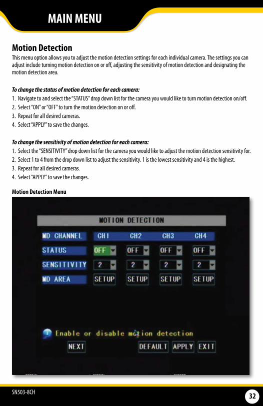
Motion Detection This menu option allows you to adjust the motion detection settings for each individual camera. The settings you can adjust include turning motion detection on or off, adjusting the sensitivity of motion detection and designating the motion detection area.
To change the status of motion detection for each camera: 1. Navigate to and select the “STATUS” drop down list for the camera you would like to turn motion detection on/off. 2. Select “ON” or “OFF” to turn the motion detection on or off. 3. Repeat for all desired cameras.4. Select “APPLY” to save the changes.
To change the sensitivity of motion detection for each camera: 1. Select the “SENSITIVITY” drop down list for the camera you would like to adjust the motion detection sensitivity for. 2. Select 1 to 4 from the drop down list to adjust the sensitivity. 1 is the lowest sensitivity and 4 is the highest. 3. Repeat for all desired cameras. 4. Select “APPLY” to save the changes.
Motion Detection Menu
MAIN MENU

SN503-8CH 33
MD AreaMotion Detection Area allows you to adjust particular areas of each camera where motion will or will not be detected. This is ideal if a camera is pointed in the direction of something that constantly has motion, such as a road, then, only the desired sections will trigger recording saving valuable space on your HDD.
To adjust the MD area: 1. Navigate to and select “SETUP” for the channel you would like to adjust the motion detection area. This will
prompt the MD Area grid.
2. Navigate to and select the squares where you do NOT want motion detected. A transparent square indicates that motion detection has been disabled.
3. Once motion detection areas have been determined, exit by right clicking or pressing “ESC,” then select “APPLY” to save settings.
Motion Area Mask
Note: It is easiest to set this up using the mouse!
NOTE: By default, the grid is entirely red: the SN503-8CH is automatically designated to detect motion throughout the whole screen.
MAIN MENU
SN503-8CH 34
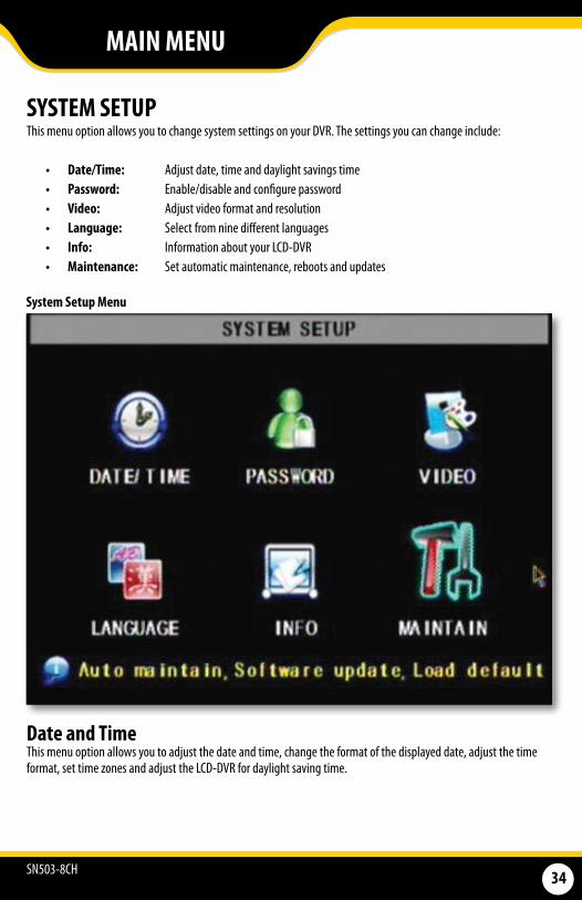
SYSTEM SETUP This menu option allows you to change system settings on your DVR. The settings you can change include:
• Date/Time: Adjust date, time and daylight savings time• Password: Enable/disable and configure password• Video: Adjust video format and resolution• Language: Select from nine different languages• Info: Information about your LCD-DVR• Maintenance: Set automatic maintenance, reboots and updates
System Setup Menu
Date and Time This menu option allows you to adjust the date and time, change the format of the displayed date, adjust the time format, set time zones and adjust the LCD-DVR for daylight saving time.
MAIN MENU
SN503-8CH 35
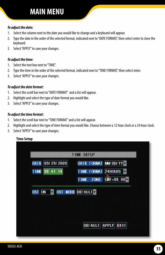
To adjust the date:1. Select the column next to the date you would like to change and a keyboard will appear.2. Type the date in the order of the selected format, indicated next to “DATE FORMAT,” then select enter to close the
keyboard. 3. Select “APPLY” to save your changes.
To adjust the time: 1. Select the text box next to “TIME”.2. Type the time in the order of the selected format, indicated next to “TIME FORMAT,” then select enter.3. Select “APPLY” to save your changes.
To adjust the date format:1. Select the scroll bar next to “DATE FORMAT” and a list will appear.2. Highlight and select the type of date format you would like. 3. Select “APPLY” to save your changes.
To adjust the time format:1. Select the scroll bar next to “TIME FORMAT” and a list will appear.2. Highlight and select the type of time format you would like. Choose between a 12 hour clock or a 24 hour clock. 3. Select “APPLY” to save your changes.
Time Setup
MAIN MENU
SN503-8CH 36
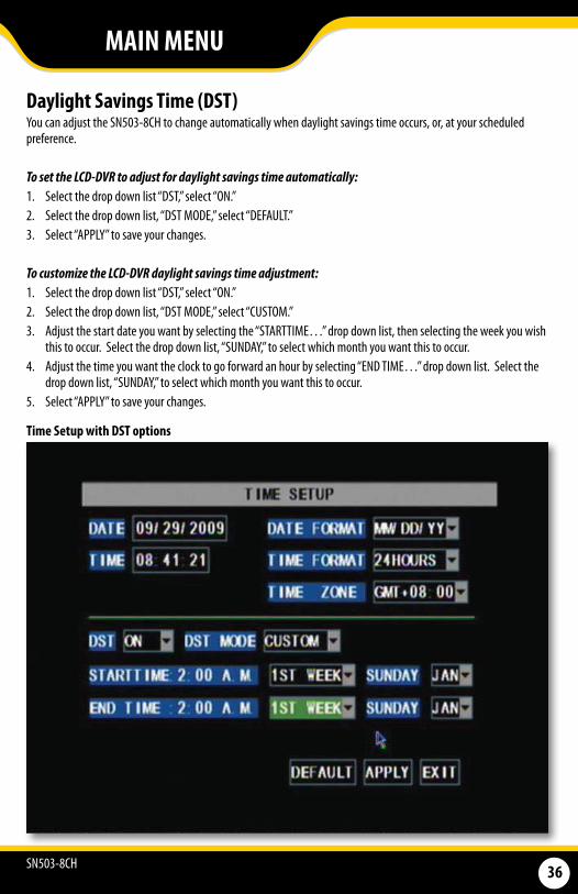
Daylight Savings Time (DST)You can adjust the SN503-8CH to change automatically when daylight savings time occurs, or, at your scheduled preference.
To set the LCD-DVR to adjust for daylight savings time automatically: 1. Select the drop down list “DST,” select “ON.” 2. Select the drop down list, “DST MODE,” select “DEFAULT.” 3. Select “APPLY” to save your changes.
To customize the LCD-DVR daylight savings time adjustment: 1. Select the drop down list “DST,” select “ON.” 2. Select the drop down list, “DST MODE,” select “CUSTOM.”3. Adjust the start date you want by selecting the “STARTTIME…” drop down list, then selecting the week you wish
this to occur. Select the drop down list, “SUNDAY,” to select which month you want this to occur.4. Adjust the time you want the clock to go forward an hour by selecting “END TIME…” drop down list. Select the
drop down list, “SUNDAY,” to select which month you want this to occur. 5. Select “APPLY” to save your changes.
Time Setup with DST options
MAIN MENU
SN503-8CH 37
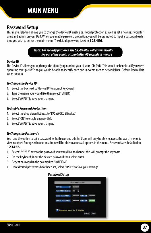
Password Setup This menu selection allows you to change the device ID, enable password protection as well as set a new password for users and admin on your DVR. When you enable password protection, you will be prompted to input a password each time you wish to access the main menu. The default password is set to 123456.
Device IDThe Device ID allows you to change the identifying number your of your LCD-DVR. This would be beneficial if you were operating multiple DVRs so you would be able to identify each one in events such as network lists. Default Device ID is set to 000000.
To Change the Device ID: 1. Select the box next to “device ID” to prompt keyboard. 2. Type the name you would like then select “ENTER.” 3. Select “APPLY” to save your changes. To Enable Password Protection: 1. Select the drop down list next to “PASSWORD ENABLE.” 2. Select “ON” to enable password(s). 3. Select “APPLY” to save your changes.
To Change the Password :You have the option to set a password for both user and admin. Users will only be able to access the search menu, to view recorded footage, whereas an admin will be able to access all options in the menu. Passwords are defaulted to 123456. 1. Select “******” next to the password you would like to change, this will prompt the keyboard.2. On the keyboard, input the desired password then select enter.3. Repeat password in the box marked “CONFIRM.” 4. Once desired passwords have been set, select “APPLY” to save your settings.
Password Setup
Note: For security purposes, the SN503-8CH will automatically log out of the admin account after 60 seconds of nonuse
MAIN MENU
SN503-8CH 38
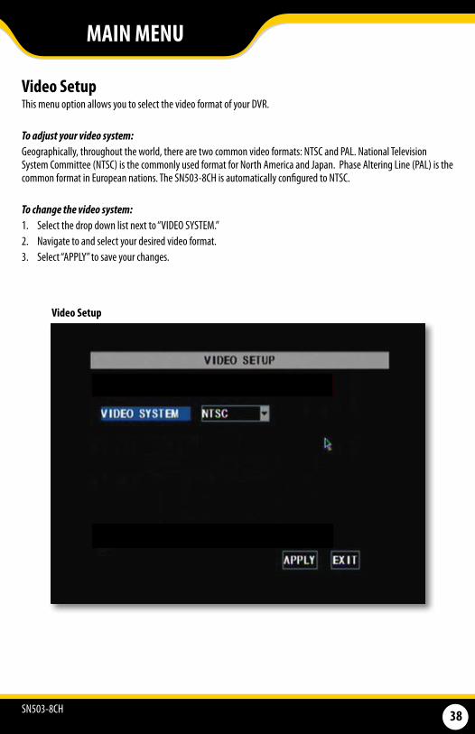
Video Setup This menu option allows you to select the video format of your DVR.
To adjust your video system: Geographically, throughout the world, there are two common video formats: NTSC and PAL. National Television System Committee (NTSC) is the commonly used format for North America and Japan. Phase Altering Line (PAL) is the common format in European nations. The SN503-8CH is automatically configured to NTSC.
To change the video system: 1. Select the drop down list next to “VIDEO SYSTEM.” 2. Navigate to and select your desired video format. 3. Select “APPLY” to save your changes.
Video Setup
MAIN MENU
SN503-8CH 39
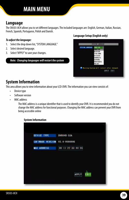
Language The SN503-8CH allows you to set different languages. The included languages are: English, German, Italian, Russian, French, Spanish, Portuguese, Polish and Danish.
To adjust the language: 1. Select the drop down list, “SYSTEM LANGUAGE.” 2. Select desired language. 3. Select “APPLY” to save your changes.
System InformationThis area allows you to view information about your LCD-DVR. The information you can view consists of:
• Device type • Software version • MAC address
The MAC address is a unique identifier that is used to identify your DVR. It is recommended you do not change the MAC address for functional purposes. Changing the MAC address can prevent your DVR from being accessible online
Language Setup (English only)
System Information
Note: Changing languages will restart the system
MAIN MENU
SN503-8CH 40
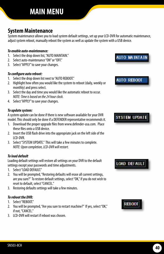
System Maintenance System maintenance allows you to load system default settings, set up your LCD-DVR for automatic maintenance, adjust system reboot, manually reboot the system as well as update the system with a USB device.
To enable auto-maintenance:1. Select the drop down list, “AUTO MAINTAIN.” 2. Select auto-maintenance “ON” or “OFF.” 3. Select “APPLY” to save your changes.
To configure auto reboot: 1. Select the drop down list next to “AUTO REBOOT.” 2. Highlight how often you would like the system to reboot (daily, weekly or
monthly) and press select. 3. Select the day and time you would like the automatic reboot to occur.
NOTE:Timeisbasedonthe24hourclock.4. Select “APPLY” to save your changes.
To update system: A system update can be done if there is new software available for your DVR model. This should only be done if a DEFENDER representative recommends it. 1. Download the proper upgrade files from www.defender-usa.com. Place
these files onto a USB device.2. Insert the USB flash drive into the appropriate jack on the left side of the
LCD-DVR. 3. Select “SYSTEM UPDATE.” This will take a few minutes to complete. NOTE:Uponcompletion,LCD-DVRwillrestart.
To load default Loading default settings will restore all settings on your DVR to the default settings except your passwords and time adjustments. 1. Select “LOAD DEFAULT.” 2. You will be prompted, “Restoring defaults will erase all current settings,
are you sure?” To restore default settings, select “OK,” if you do not wish to reset to default, select “CANCEL.”
3. Restoring defaults settings will take a few minutes.
To reboot the DVR: 1. Select “REBOOT.” 2. You will be prompted, “Are you sure to restart machine?” If yes, select “OK,”
if not, “CANCEL.” 3. LCD-DVR will restart if reboot was chosen.
MAIN MENU
SN503-8CH 41
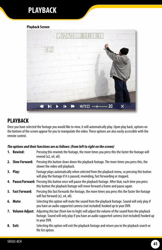
PLAYBACKOnce you have selected the footage you would like to view, it will automatically play. Upon play back, options on the bottom of the screen appear for you to manipulate the video. These options are also easily accessible with the remote control.
The options and their functions are as follows: (from left to right on the screen) 1. Rewind: Pressing this rewinds the footage, the more times you press this the faster the footage will
rewind (x2, x4, x8).2. Slow Forward: Pressing this button slows down the playback footage. The more times you press this, the
slower the video will playback. 3. Play: Footage plays automatically when selected from the playback menu, so pressing this button
will play the footage if it is paused, rewinding, fast forwarding or stopped. 4. Pause/Forward: Pressing this button once will pause the playback footage. After that, each time you press
this button the playback footage will move forward a frame and pause again. 5. Fast Forward: Pressing this fast forwards the footage, the more times you press this the faster the footage
will fast forward (x2, x4, x8).6. Mute: Selecting this option will mute the sound from the playback footage. Sound will only play if
you have an audio supported camera (not included) hooked up to your DVR. 7. Volume Adjust: Adjusting this bar (from low to high) will adjust the volume of the sound from the playback
footage. Sound will only play if you have an audio supported camera (not included) hooked up to your DVR.
8. Exit: Selecting this option will exit the playback footage and return you to the playback search or file list option.
PLAYBACK
Playback Screen
SN503-8CH 42
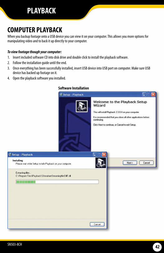
COMPUTER PLAYBACK When you backup footage onto a USB device you can view it on your computer. This allows you more options for manipulating video and to back it up directly to your computer.
To view footage though your computer: 1. Insert included software CD into disk drive and double click to install the playback software.2. Follow the installation guide until the end. 3. Once everything has been successfully installed, insert USB device into USB port on computer. Make sure USB
device has backed up footage on it. 4. Open the playback software you installed.
Software Installation
PLAYBACK
SN503-8CH 43
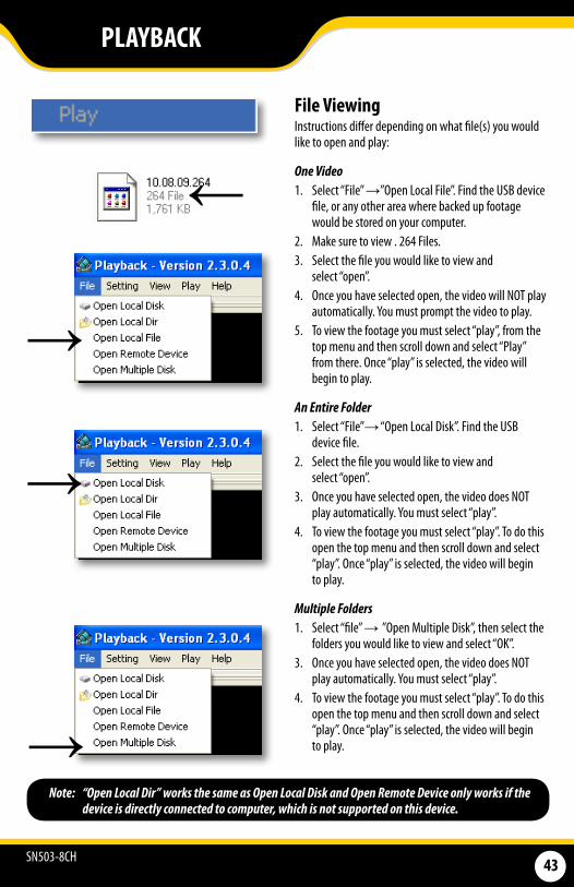
Note: “Open Local Dir” works the same as Open Local Disk and Open Remote Device only works if the device is directly connected to computer, which is not supported on this device.
PLAYBACK
→
→
→
File ViewingInstructions differ depending on what file(s) you would like to open and play:
One Video 1. Select “File” →”Open Local File”. Find the USB device
file, or any other area where backed up footage would be stored on your computer.
2. Make sure to view . 264 Files. 3. Select the file you would like to view and
select “open”. 4. Once you have selected open, the video will NOT play
automatically. You must prompt the video to play.5. To view the footage you must select “play”, from the
top menu and then scroll down and select “Play” from there. Once “play” is selected, the video will begin to play.
An Entire Folder1. Select “File”→ “Open Local Disk”. Find the USB
device file.2. Select the file you would like to view and
select “open”. 3. Once you have selected open, the video does NOT
play automatically. You must select “play”.4. To view the footage you must select “play”. To do this
open the top menu and then scroll down and select “play”. Once “play” is selected, the video will begin to play.
Multiple Folders 1. Select “file” → ”Open Multiple Disk”, then select the
folders you would like to view and select “OK”. 3. Once you have selected open, the video does NOT
play automatically. You must select “play”.4. To view the footage you must select “play”. To do this
open the top menu and then scroll down and select “play”. Once “play” is selected, the video will begin to play.
→
SN503-8CH 44
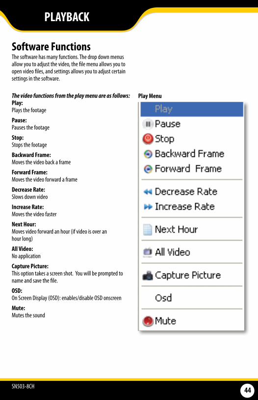
Software FunctionsThe software has many functions. The drop down menus allow you to adjust the video, the file menu allows you to open video files, and settings allows you to adjust certain settings in the software.
The video functions from the play menu are as follows: Play: Plays the footage
Pause: Pauses the footage
Stop: Stops the footage
Backward Frame: Moves the video back a frame
Forward Frame: Moves the video forward a frame
Decrease Rate: Slows down video
Increase Rate: Moves the video faster
Next Hour: Moves video forward an hour (if video is over an hour long)
All Video: No application
Capture Picture:This option takes a screen shot. You will be prompted to name and save the file.
OSD: On Screen Display (OSD): enables/disable OSD onscreen
Mute:Mutes the sound
Play Menu
PLAYBACK
SN503-8CH 45
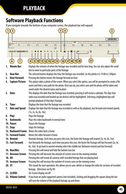
1. Minute Bar: Displays the minutes of when the footage was recorded and for how long. You can also adjust the small box to move to particular parts of the footage
2. Hour Bar: The selected button displays the hour the footage was recorded. (in this photo it is 14:00 or 2:00pm) 3. Hour Forward: Pressing this button moves the footage forward an hour4. Capture Picture: This option takes a photo of the screen. When you select this option, you will be prompted to create a file
name and find a save path for the photo. Once you do, you select save and the photo will be taken and saved under the desired name and location
5. Date: This displays the date that the footage was recorded; pressing it will reveal a calendar. The days that video was recorded and backed up (on device) will be highlighted. Selecting a highlighted day will prompt playback of that day’s footage
6. Time: Displays the time that the footage was recorded7. Date and Speed: Displays the date that the footage was recorded as well as the playback, fast forward and rewind speeds.
(1x, 2x, 4x, 8x, 16x) 8. Play: Plays the footage9. Backwards: Plays the video backwards in normal time10. Pause: Pauses the footage11. Stop: Stops the footage12. Backward Frame: Moves the video back a frame 13. Forward Frame: Moves the video forward a frame14. Rewind: Rewinds footage. Each time you press this icon, the faster the footage will rewind (2x, 4x, 8x, 16x) 15. Fast Forward: Fast forwards the footage, each time you press this icon, the faster the footage will fast forward (2x, 4x,
8x, 16x). To go back to normal viewing select the middle bar (between rewind and fast forward) 16. Max/Min: Pressing this will reveal and hide the bottom icon bar17. Decrease Screen: Pressing this will decrease the amount of screens seen on the viewing window 18. All: Pressing this will reveal all cameras with recorded footage that are playing back19. Increase Screen: Pressing this will increase the number of screens seen on the viewing screen20. ST: This stands for start operation; this allows you to save, delete or change the video for sections of recorded
footage. (Directions on Pg 49) 21. (i)/OSD: On-Screen Display on/off22. Volume Control: If you have an audio supported camera (not included), clicking and dragging the square along the bar
will turn the volume of the playback footage up and down.
Software Playback Functions If you navigate towards the bottom of you computer screen, the playback bar will expand:
PLAYBACK
SN503-8CH 46
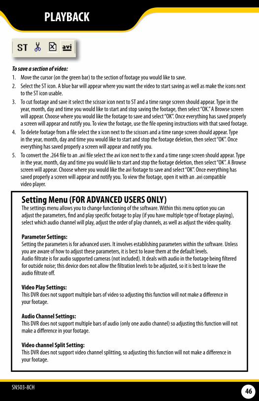
To save a section of video: 1. Move the cursor (on the green bar) to the section of footage you would like to save. 2. Select the ST icon. A blue bar will appear where you want the video to start saving as well as make the icons next
to the ST icon usable. 3. To cut footage and save it select the scissor icon next to ST and a time range screen should appear. Type in the
year, month, day and time you would like to start and stop saving the footage, then select “OK.” A Browse screen will appear. Choose where you would like the footage to save and select “OK”. Once everything has saved properly a screen will appear and notify you. To view the footage, use the file opening instructions with that saved footage.
4. To delete footage from a file select the x icon next to the scissors and a time range screen should appear. Type in the year, month, day and time you would like to start and stop the footage deletion, then select “OK”. Once everything has saved properly a screen will appear and notify you.
5. To convert the .264 file to an .avi file select the avi icon next to the x and a time range screen should appear. Type in the year, month, day and time you would like to start and stop the footage deletion, then select “OK”. A Browse screen will appear. Choose where you would like the avi footage to save and select “OK”. Once everything has saved properly a screen will appear and notify you. To view the footage, open it with an .avi compatible video player.
PLAYBACK
Setting Menu (FOR ADVANCED USERS ONLY)The settings menu allows you to change functioning of the software. Within this menu option you can adjust the parameters, find and play specific footage to play (if you have multiple type of footage playing), select which audio channel will play, adjust the order of play channels, as well as adjust the video quality.
Parameter Settings: Setting the parameters is for advanced users. It involves establishing parameters within the software. Unless you are aware of how to adjust these parameters, it is best to leave them at the default levels. Audio filtrate is for audio supported cameras (not included). It deals with audio in the footage being filtered for outside noise; this device does not allow the filtration levels to be adjusted, so it is best to leave the audio filtrate off.
Video Play Settings: This DVR does not support multiple bars of video so adjusting this function will not make a difference in your footage.
Audio Channel Settings: This DVR does not support multiple bars of audio (only one audio channel) so adjusting this function will not make a difference in your footage.
Video channel Split Setting: This DVR does not support video channel splitting, so adjusting this function will not make a difference in your footage.
SN503-8CH 47
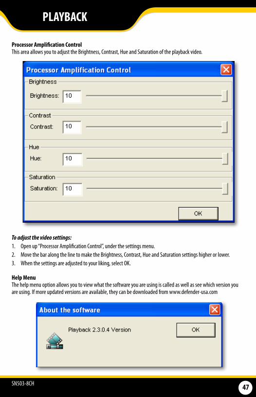
Processor Amplification ControlThis area allows you to adjust the Brightness, Contrast, Hue and Saturation of the playback video.
To adjust the video settings: 1. Open up “Processor Amplification Control”, under the settings menu. 2. Move the bar along the line to make the Brightness, Contrast, Hue and Saturation settings higher or lower. 3. When the settings are adjusted to your liking, select OK.
Help Menu The help menu option allows you to view what the software you are using is called as well as see which version you are using. If more updated versions are available, they can be downloaded from www.defender-usa.com
PLAYBACK

SN503-8CH 48
NETWORK GUIDE
REQUIREMENTSYou will need to have: The DVR connected to a router
The router connected to the Internet
A PC or laptop that is connected to the same router as the DVR. The PC can be connected by a wired or wireless connection
Internet Explorer 6.0 or higher (to check your version of Internet Explorer open I.E. In the top Menu bar select “Help” and then select “About Internet Explorer”. The version of I.E. will be displayed.)
A genuine and fully updated version of Windows XP, Vista or newer
Note: The computer and DVR need to be connected to the same router for initial setup. A computer will not always be necessary at the location to view the DVR.
1. Power off the DVR by removing the power cable from the left side of the LCD-DVR or flip the power switch.
2. Connect the included network cable to the left of the DVR in the Ethernet port (LAN).
3. Connect the other end of the network cable to an available port on the router.
4. Power on the DVR by reconnecting the power cable to the back of the DVR or by switching the power on.
CONNECTING LCD-DVR TO A ROUTER

SN503-8CH 49
1. Access the main menu then navigate to and select “NETWORK SETUP.” 2. Make sure the “IP Mode” is set to DHCP. This setting is acceptable for most users. • If the IP mode is not set to DHCP, use the drop down list next to “TYPE” and select “DHCP.” You must select
“APPLY” and exit all menus for the DVR to restart and retrieve an IP address.3. Write down your IP address, port and web port. This information will be used in the next few steps to view the
DVR on your computer as well viewing the DVR over the Internet.
→ONCE ACQUIRED,
YOUR IP ADDRESS WILL APPEAR HERE
NETWORK GUIDE
Finding your DVR’s IP AddressBy default, the DVR IP mode is set to DHCP. This means the SN503-8CH will automatically retrieve an IP address from the router that it is connected to. Unless your network requires a static IP address, leave the IP mode set to DHCP.
Note: If your router does not support DHCP, contact your network administrator to supply you with the proper IP information. If the DVR needs to store PPPoE (DSL/ADSL) settings contact your ISP (Internet Service Provider) for the proper IP address settings.
Every computer that is accessing the DVR will need to be configured to download and run ActiveX controls. This change only needs to be made one time on the computer that is accessing the DVR. This can be done by either of the two methods below:
Preparing Your Computer for Viewing the LCD-DVR:
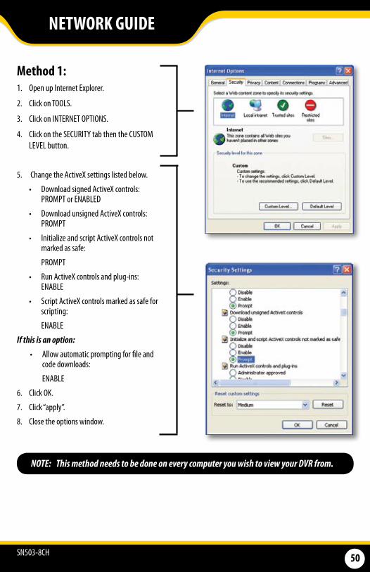
SN503-8CH 50
Method 1: 1. Open up Internet Explorer.
2. Click on TOOLS.
3. Click on INTERNET OPTIONS.
4. Click on the SECURITY tab then the CUSTOM LEVEL button.
5. Change the ActiveX settings listed below.
• Download signed ActiveX controls: PROMPT or ENABLED
• Download unsigned ActiveX controls: PROMPT
• Initialize and script ActiveX controls not marked as safe:
PROMPT
• Run ActiveX controls and plug-ins: ENABLE
• Script ActiveX controls marked as safe for scripting:
ENABLE
If this is an option:
• Allow automatic prompting for file and code downloads:
ENABLE
6. Click OK.
7. Click “apply”.
8. Close the options window.
NETWORK GUIDE
NOTE: This method needs to be done on every computer you wish to view your DVR from.
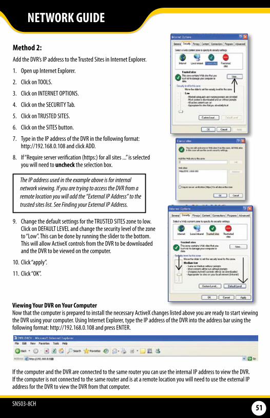
SN503-8CH 51
NETWORK GUIDE
Method 2:Add the DVR’s IP address to the Trusted Sites in Internet Explorer.
1. Open up Internet Explorer.
2. Click on TOOLS.
3. Click on INTERNET OPTIONS.
4. Click on the SECURITY Tab.
5. Click on TRUSTED SITES.
6. Click on the SITES button.
7. Type in the IP address of the DVR in the following format: http://192.168.0.108 and click ADD.
8. If “Require server verification (https:) for all sites ...” is selected you will need to uncheck the selection box.
9. Change the default settings for the TRUSTED SITES zone to low. Click on DEFAULT LEVEL and change the security level of the zone to “Low”. This can be done by running the slider to the bottom. This will allow ActiveX controls from the DVR to be downloaded and the DVR to be viewed on the computer.
10. Click “apply”.
11. Click “OK”.
TheIPaddressusedintheexampleaboveisforinternalnetworkviewing.IfyouaretryingtoaccesstheDVRfromaremotelocationyouwilladdthe“ExternalIPAddress”tothetrustedsiteslist.SeeFindingyourExternalIPAddress.
Viewing Your DVR on Your ComputerNow that the computer is prepared to install the necessary ActiveX changes listed above you are ready to start viewing the DVR using your computer. Using Internet Explorer, type the IP address of the DVR into the address bar using the following format: http://192.168.0.108 and press ENTER.
If the computer and the DVR are connected to the same router you can use the internal IP address to view the DVR. If the computer is not connected to the same router and is at a remote location you will need to use the external IP address for the DVR to view the DVR from that computer.
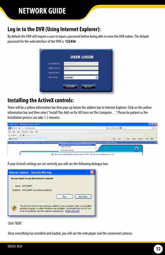
SN503-8CH 52
Log in to the DVR (Using Internet Explorer):By default the DVR will require a user to input a password before being able to view the DVR online. The default password for the web interface of the DVR is: 123456
Installing the ActiveX controls:There will be a yellow information bar that pops up below the address bar in Internet Explorer. Click on the yellow information bar and then select “Install This Add-on for All Users on This Computer…”. Please be patient as the installation process can take 1-2 minutes.
If your ActiveX settings are set correctly you will see the following dialogue box.
Click “RUN”.
Once everything has installed and loaded, you will see the web player and the connected cameras.
NETWORK GUIDE
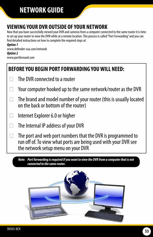
SN503-8CH 53
VIEWING YOUR DVR OUTSIDE OF YOUR NETWORKNow that you have successfully viewed your DVR and cameras from a computer connected to the same router it is time to set up your router to view the DVR while at a remote location. This process is called “Port Forwarding” and you can find detailed instructions on how to complete the required steps at: Option 1www.defender-usa.com/network Option 2www.portforward.com
BEFORE YOU BEGIN PORT FORWARDING YOU WILL NEED:
The DVR connected to a router
Your computer hooked up to the same network/router as the DVR
The brand and model number of your router (this is usually located on the back or bottom of the router)
Internet Explorer 6.0 or higher
The Internal IP address of your DVR
The port and web port numbers that the DVR is programmed to run off of. To view what ports are being used with your DVR see the network setup menu on your DVR
Note: Port forwarding is required if you want to view the DVR from a computer that is not connected to the same router.
NETWORK GUIDE
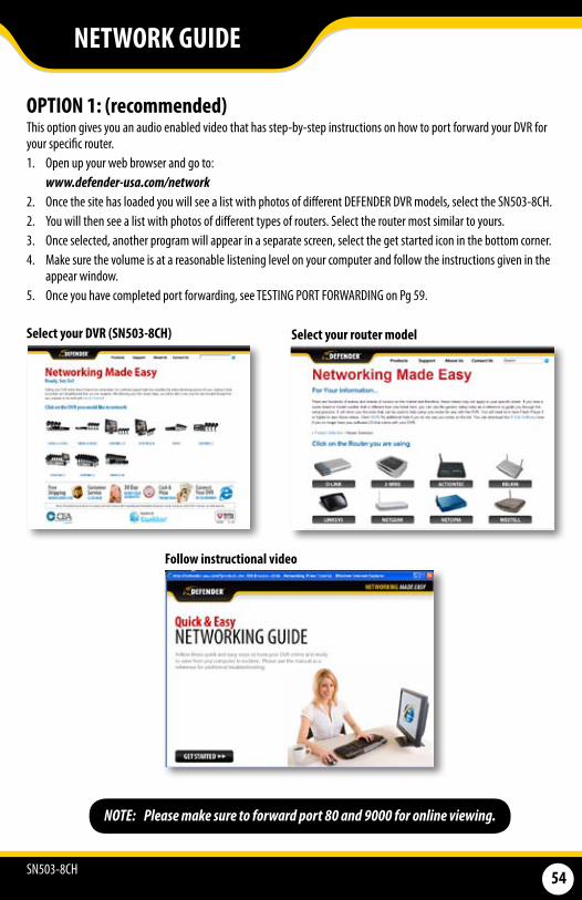
SN503-8CH 54
Select your DVR (SN503-8CH) Select your router model
Follow instructional video
NETWORK GUIDE
NOTE: Please make sure to forward port 80 and 9000 for online viewing.
OPTION 1: (recommended)This option gives you an audio enabled video that has step-by-step instructions on how to port forward your DVR for your specific router. 1. Open up your web browser and go to: www.defender-usa.com/network2. Once the site has loaded you will see a list with photos of different DEFENDER DVR models, select the SN503-8CH. 2. You will then see a list with photos of different types of routers. Select the router most similar to yours. 3. Once selected, another program will appear in a separate screen, select the get started icon in the bottom corner. 4. Make sure the volume is at a reasonable listening level on your computer and follow the instructions given in the
appear window.5. Once you have completed port forwarding, see TESTING PORT FORWARDING on Pg 59.
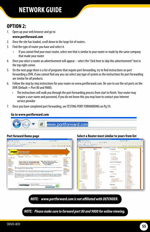
SN503-8CH 55
OPTION 2: 1. Open up your web browser and go to:
www.portforward.com 2. Once the site has loaded, scroll down to the large list of routers. 3. Find the type of router you have and select it.
• If you cannot find your exact router, select one that is similar to your router or made by the same company that made your router
4. Once you select a router an advertisement will appear – select the “click here to skip this advertisement” text in the top right corner.
5. On the next page there is a list of programs that require port forwarding, try to find instructions on port forwarding a DVR, if you cannot find any you can select any type of system as the instructions for port forwarding are similar for all products.
6. Follow the step by step instructions for your router on www.portforward.com. Be sure to use the set ports on the DVR (Default = Port 80 and 9000). • The instructions will walk you through the port forwarding process from start to finish. Your router may
require a user name and password, if you do not know this you may have to contact your Internet service provider
7. Once you have completed port forwarding, see TESTING PORT FORWARDING on Pg 59.
Port forward Home page Select a Router most similar to yours from list
NOTE: www.portforward.com is not affiliated with DEFENDER.
Go to www.portforward.com
NETWORK GUIDE
NOTE: Please make sure to forward port 80 and 9000 for online viewing.

SN503-8CH 56
TESTING PORT FORWARDING
If you would like to see if your port forwarding worked, follow these steps : 1. Open a web browser and type in www.whatsmyip.org. 2. Your External IP address will be listed on the top center of the screen, make sure to write it down. This is the
address that you can use when not at home to connect onto your DVR.3. Open another web browser.4. Type in www.canyouseeme.org. This site also allows you to see your external IP address. 5. You will see your external IP address and underneath it you will see a box saying “what port?” 6. In the box, put the port numbers you set the DVR to. The default ports are 80 and 9000 (you have to forward both,
please make sure you check both ports.) 7. Click the check button and scroll down. 8. You will see a message that tells you that it can successfully see your port. This means you have successfully port
forwarded. 9. If you receive an error message please view “IF YOU CANNOT CONNECT” on Pg. 60. If you’re still having trouble you
can always contact DEFENDER’s 24/7 support team.
NOTE: www.whatsmyip.org and www.canyouseeme.org are not affiliated with DEFENDER in any way.
Write down your external IP address
Type in your the port you forwarded (Default port is 80)
NETWORK GUIDE
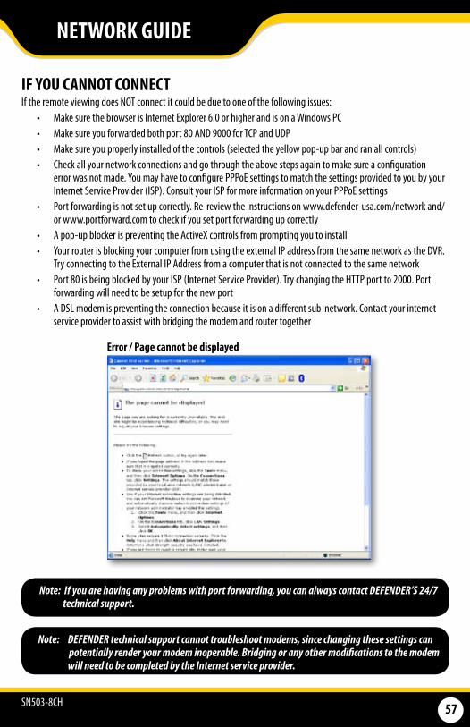
SN503-8CH 57
IF YOU CANNOT CONNECTIf the remote viewing does NOT connect it could be due to one of the following issues:
• Make sure the browser is Internet Explorer 6.0 or higher and is on a Windows PC• Make sure you forwarded both port 80 AND 9000 for TCP and UDP • Make sure you properly installed of the controls (selected the yellow pop-up bar and ran all controls) • Check all your network connections and go through the above steps again to make sure a configuration
error was not made. You may have to configure PPPoE settings to match the settings provided to you by your Internet Service Provider (ISP). Consult your ISP for more information on your PPPoE settings
• Port forwarding is not set up correctly. Re-review the instructions on www.defender-usa.com/network and/or www.portforward.com to check if you set port forwarding up correctly
• A pop-up blocker is preventing the ActiveX controls from prompting you to install• Your router is blocking your computer from using the external IP address from the same network as the DVR.
Try connecting to the External IP Address from a computer that is not connected to the same network• Port 80 is being blocked by your ISP (Internet Service Provider). Try changing the HTTP port to 2000. Port
forwarding will need to be setup for the new port• A DSL modem is preventing the connection because it is on a different sub-network. Contact your internet
service provider to assist with bridging the modem and router together
Note: DEFENDER technical support cannot troubleshoot modems, since changing these settings can potentially render your modem inoperable. Bridging or any other modifications to the modem
will need to be completed by the Internet service provider.
NETWORK GUIDE
Error / Page cannot be displayed
Note: If you are having any problems with port forwarding, you can always contact DEFENDER’S 24/7 technical support.
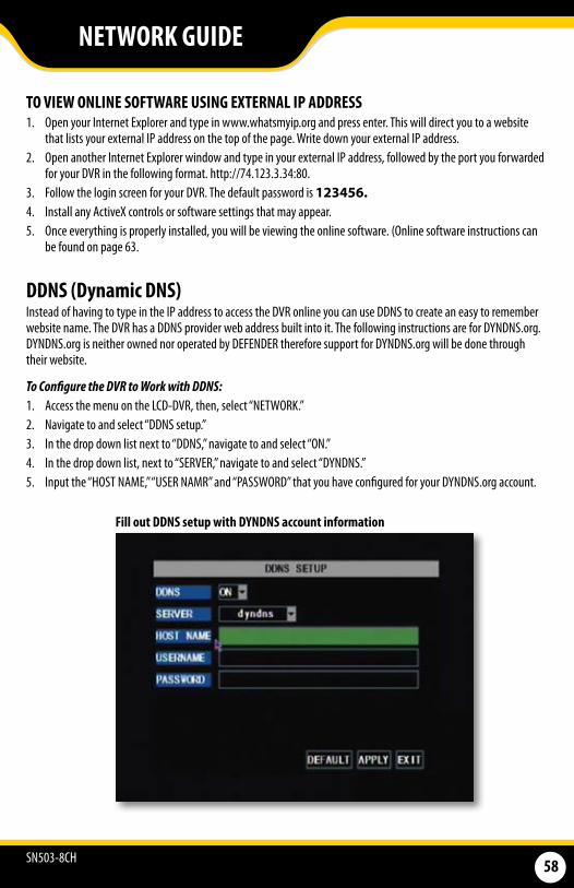
SN503-8CH 58
DDNS (Dynamic DNS)Instead of having to type in the IP address to access the DVR online you can use DDNS to create an easy to remember website name. The DVR has a DDNS provider web address built into it. The following instructions are for DYNDNS.org. DYNDNS.org is neither owned nor operated by DEFENDER therefore support for DYNDNS.org will be done through their website.
To Configure the DVR to Work with DDNS:1. Access the menu on the LCD-DVR, then, select “NETWORK.” 2. Navigate to and select “DDNS setup.” 3. In the drop down list next to “DDNS,” navigate to and select “ON.” 4. In the drop down list, next to “SERVER,” navigate to and select “DYNDNS.” 5. Input the “HOST NAME,” “USER NAMR” and “PASSWORD” that you have configured for your DYNDNS.org account.
Fill out DDNS setup with DYNDNS account information
TO VIEW ONLINE SOFTWARE USING EXTERNAL IP ADDRESS 1. Open your Internet Explorer and type in www.whatsmyip.org and press enter. This will direct you to a website
that lists your external IP address on the top of the page. Write down your external IP address. 2. Open another Internet Explorer window and type in your external IP address, followed by the port you forwarded
for your DVR in the following format. http://74.123.3.34:80.3. Follow the login screen for your DVR. The default password is 123456.4. Install any ActiveX controls or software settings that may appear. 5. Once everything is properly installed, you will be viewing the online software. (Online software instructions can
be found on page 63.
NETWORK GUIDE
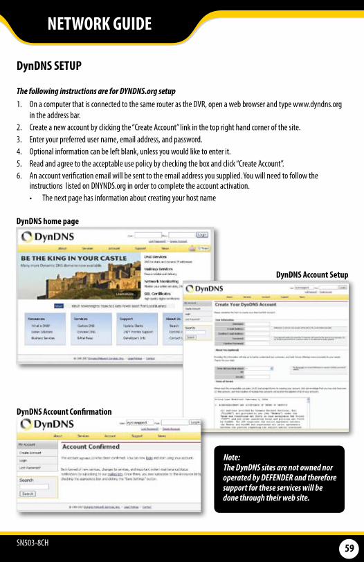
SN503-8CH 59
DynDNS SETUP
The following instructions are for DYNDNS.org setup 1. On a computer that is connected to the same router as the DVR, open a web browser and type www.dyndns.org
in the address bar.2. Create a new account by clicking the “Create Account” link in the top right hand corner of the site.3. Enter your preferred user name, email address, and password.4. Optional information can be left blank, unless you would like to enter it. 5. Read and agree to the acceptable use policy by checking the box and click “Create Account”.6. An account verification email will be sent to the email address you supplied. You will need to follow the
instructions listed on DNYNDS.org in order to complete the account activation.• The next page has information about creating your host name
DynDNS home page
DynDNS Account Setup
DynDNS Account Confirmation
Note: The DynDNS sites are not owned nor operated by DEFENDER and therefore support for these services will be done through their web site.
NETWORK GUIDE

SN503-8CH 60
LOG INTO THE ACCOUNT AND SETUP A DDNS HOST
To set up a DynDNS name for your DVR:1. Enter the DYNDNS.org user name and password you created and click login.2. Click on the “Services” button located on the menu bar.3. Click on the “Dynamic DNS” link.4. Click on the “Get Started” link located on right side of the screen.5. Type in a desired host name. We recommend you use your name, family name or your business’ name, as long as
it is easy to remember.6. Choose a domain name from the drop down menu. We recommend using dyndns.org. 7. In the IP address field, type in the external IP address that your DVR is connected to. 8. Leave all of the other options as they are, and click “Create New Host”.9. Follow on screen instructions to activate and view your free DDNS host name. 10. Be sure to input the proper account information on your DVR’s DDNS setup menu before viewing.
Select the Services Button Select Dynamic DNS
↑ ↑
Insert account info
NETWORK GUIDE
Select “Get Started” ↑
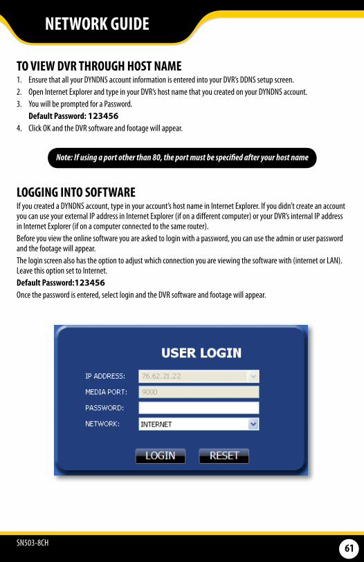
SN503-8CH 61
TO VIEW DVR THROUGH HOST NAME1. Ensure that all your DYNDNS account information is entered into your DVR’s DDNS setup screen. 2. Open Internet Explorer and type in your DVR’s host name that you created on your DYNDNS account. 3. You will be prompted for a Password. Default Password: 1234564. Click OK and the DVR software and footage will appear.
Note: If using a port other than 80, the port must be specified after your host name
LOGGING INTO SOFTWARE If you created a DYNDNS account, type in your account’s host name in Internet Explorer. If you didn’t create an account you can use your external IP address in Internet Explorer (if on a different computer) or your DVR’s internal IP address in Internet Explorer (if on a computer connected to the same router).Before you view the online software you are asked to login with a password, you can use the admin or user password and the footage will appear. The login screen also has the option to adjust which connection you are viewing the software with (internet or LAN). Leave this option set to Internet.Default Password:123456Once the password is entered, select login and the DVR software and footage will appear.
NETWORK GUIDE
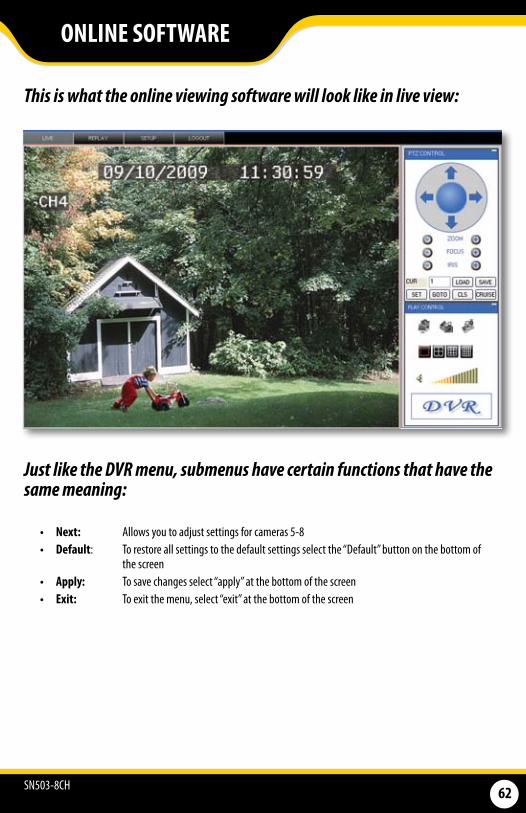
SN503-8CH 62
Just like the DVR menu, submenus have certain functions that have the same meaning:
• Next: Allows you to adjust settings for cameras 5-8• Default: To restore all settings to the default settings select the “Default” button on the bottom of
the screen• Apply: To save changes select “apply” at the bottom of the screen • Exit: To exit the menu, select “exit” at the bottom of the screen
ONLINE SOFTWARE
This is what the online viewing software will look like in live view:
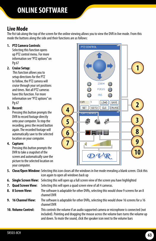
SN503-8CH 63
ONLINE SOFTWARE
Live Mode The fist tab along the top of the screen for the online viewing allows you to view the DVR in live mode. From this mode the buttons along the side and their functions are as follows:
5. Close/Open Window: Selecting this icon closes all the windows in live mode revealing a blank screen. Click this icon again to open all windows back up
6. Single Screen View: Selecting this will open up a full screen view of the screen you have highlighted7. Quad Screen View: Selecting this will open a quad screen view of all 4 cameras. 8. 8 Screen View: The software is adaptable for other DVRs, selecting this would show 9 screens for an 8
channel DVR 9. 16 Channel View: The software is adaptable for other DVRs, selecting this would show 16 screens for a 16
channel DVR 10. Volume Control: This controls the volume if an audio supported camera or microphone is connected (not
included). Pointing and dragging the mouse across the volume bars turns the volume up and down. To mute the sound, click the speaker icon next to the volume bars
1. PTZ Camera Controls: Selecting this function opens
up PTZ control menu. For more information see “PTZ options” on Pg 67
2. Cruise Setup: This function allows you to
setup directions for the PTZ to follow, the PTZ camera will cruise through your set positions and times. Not all PTZ cameras have this function. For more information see “PTZ options” on Pg 67
3. Record: Pressing this button prompts the
DVR to record footage directly onto your computer. To stop the recording, press the record button again. The recorded footage will automatically save to the selected location on your computer.
4. Capture: Pressing this button prompts the
DVR to take a snapshot of the screen and automatically save the picture to the selected location on your computer.
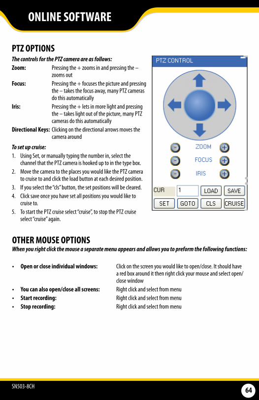
SN503-8CH 64
ONLINE SOFTWARE
The controls for the PTZ camera are as follows: Zoom: Pressing the + zooms in and pressing the –
zooms out Focus: Pressing the + focuses the picture and pressing
the – takes the focus away, many PTZ cameras do this automatically
Iris: Pressing the + lets in more light and pressing the – takes light out of the picture, many PTZ cameras do this automatically
Directional Keys: Clicking on the directional arrows moves the camera around
To set up cruise: 1. Using Set, or manually typing the number in, select the
channel that the PTZ camera is hooked up to in the type box. 2. Move the camera to the places you would like the PTZ camera
to cruise to and click the load button at each desired position. 3. If you select the “cls” button, the set positions will be cleared. 4. Click save once you have set all positions you would like to
cruise to. 5. To start the PTZ cruise select “cruise”, to stop the PTZ cruise
select “cruise” again.
When you right click the mouse a separate menu appears and allows you to preform the following functions:
• Open or close individual windows: Click on the screen you would like to open/close. It should have a red box around it then right click your mouse and select open/close window
• You can also open/close all screens: Right click and select from menu• Start recording: Right click and select from menu• Stop recording: Right click and select from menu
PTZ OPTIONS
OTHER MOUSE OPTIONS

SN503-8CH 65
ONLINE SOFTWARE
To search through footage: 1. Select the date you would like to view the footage from on the calendar by double clicking on the particular date.
If the date has available footage, it will be in bold. 2. Make sure the menu is not being accessed, if the DVR’s menu is being accessed by another user, you will be unable
to retrieve or view footage.3. It should take a few moments to load the available footage. The footage will appear in the space below
the calendar. 4. The list will display the footage in the following format:
• The time the footage was recorded; the channel the footage was recorded on, the size of the footage5. Select the footage you would like to view from this list and double click it to play it. 6. If you would like to refresh to the newest footage being recorded, select refresh. The most recently recorded
footage will appear at the bottom of the list.
Search for Selected Footage:1. Using the scroll lists located under the calendar, select the camera and type of footage you would like to view. 2. Select “search” and only the type of footage from the camera selected will be displayed in the list below.
PLAYBACKThis tab allows you to search, view and backup previously recorded footage that is stored on your LCD-DVR’s HDD. You can also narrow down your search by type of footage and what camera it was recorded from.
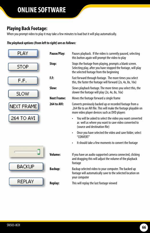
SN503-8CH 66
Playing Back Footage: When you prompt video to play it may take a few minutes to load but it will play automatically.
ONLINE SOFTWARE
The playback options (from left to right) are as follows:
Pause/Play: Pauses playback. If the video is currently paused, selecting this button again will prompt the video to play
Stop: Stops the footage from playing, prompts a blank screen. Selecting play, after you have stopped the footage, will play the selected footage from the beginning
F.F: Fast forward through footage. The more times you select this, the faster the footage will forward (2x, 4x, 8x, 16x)
Slow: Slows playback footage. The more times you select this, the slower the footage will play (2x, 4x, 8x, 16x)
Next Frame: Moves the footage forward a single frame
264 to AVI: Converts previously backed up or recorded footage from a .264 file to an AVI file. This will make the footage playable on more video player devices such as DVD players
• You will be asked to select the video you want converted as well as where you want to save video converted to (source and destination file)
• Once you have selected the video and save folder, select “CONVERT”
• It should take a few moments to convert the footage
Volume: If you have an audio supported camera connected, clicking and dragging this will adjust the volume of the playback footage
Backup: Backup selected video to your computer. The backed up footage will automatically save to the selected location on your computer
Replay: This will replay the last footage viewed

SN503-8CH 67
Record ModeThe DVR allows you to choose whether it always records, or if it records based on a schedule that you set up yourself.
To program your DVR to always record: 1. Select the drop down menu beside
“Record Mode”. 2. Highlight the word “Power Up” and
press select. 3. Select “apply” to save settings.
To set your DVR for schedule record: 1. Select the drop down menu beside
“Record Mode”. 2. Highlight the words “TIMER” and
press select. 3. Select “apply” to save settings.
To set your record schedule: This DVR allows you to set different schedules for each channel as well as set what days the DVR will follow the set schedule. You can also select if it constantly records or if it only records when motion or the alarm is detected. 1. From the record setup menu on your DVR, make sure your DVR is set to “TIMER RECORD”. 2. Select the word “SCHEDULE” beside the record mode drop down list. 3. This will bring you to a separate menu.4. Select the drop down list beside the word “CHANNEL” and highlight the camera you would like to set a
schedule for.
SETUP This tab allows you to go through particular settings and make adjustments to the LCD-DVR. The menu options you can adjust include:
• Record • Alarm • PTZ• Network• Setting• Host Info
Each function works much like the menu option on the DVR.
Record Options
ONLINE SOFTWARE
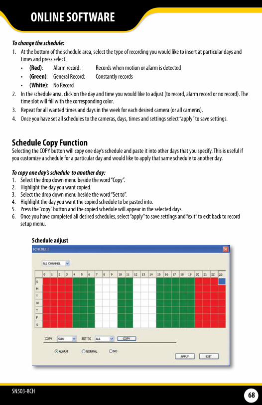
SN503-8CH 68
To change the schedule:1. At the bottom of the schedule area, select the type of recording you would like to insert at particular days and
times and press select. • (Red): Alarm record: Records when motion or alarm is detected• (Green): General Record: Constantly records • (White): No Record
2. In the schedule area, click on the day and time you would like to adjust (to record, alarm record or no record). The time slot will fill with the corresponding color.
3. Repeat for all wanted times and days in the week for each desired camera (or all cameras). 4. Once you have set all schedules to the cameras, days, times and settings select “apply” to save settings.
ONLINE SOFTWARE
Schedule Copy FunctionSelecting the COPY button will copy one day’s schedule and paste it into other days that you specify. This is useful if you customize a schedule for a particular day and would like to apply that same schedule to another day.
To copy one day’s schedule to another day: 1. Select the drop down menu beside the word “Copy”. 2. Highlight the day you want copied. 3. Select the drop down menu beside the word “Set to”. 4. Highlight the day you want the copied schedule to be pasted into. 5. Press the “copy” button and the copied schedule will appear in the selected days. 6. Once you have completed all desired schedules, select “apply” to save settings and “exit” to exit back to record
setup menu.
Schedule adjust
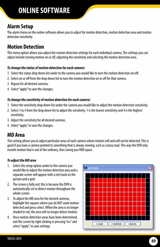
SN503-8CH 69
ONLINE SOFTWARE
MD AreaThis setting allows you to adjust particular areas of each camera where motion will and will not be detected. This is good if you have a camera pointed to something that is always moving, such as a busy road. This way the DVR only records motion that is out of the ordinary, thus saving you HDD space.
To adjust the MD area 1. Select the setup option under to the camera you
would like to adjust the motion detection area and a separate screen will appear with a red mask on the picture and a grid.
2. The screen is fully red; this is because the DVR is automatically set to detect motion throughout the whole screen.
3. To adjust the MD area for the desired cameras, highlight the squares where you do NOT want motion detected and press select. When the area is no longer shaded in red, the area will no longer detect motion.
4. Once motion detection areas have been determined, exit the screen by right clicking or pressing “esc” and select “apply”, to save settings.
Alarm Setup The alarm menu on the online software allows you to adjust for motion detection, motion detection area and motion detection sensitivity.
Motion Detection This menu option allows you adjust the motion detection settings for each individual camera. The settings you can adjust include turning motion on or off, adjusting the sensitivity and selecting the motion detection area.
To change the status of motion detection for each camera: 1. Select the status drop down list under to the camera you would like to turn the motion detection on/off.2. Select on or off from the drop down list to turn the motion detection on or off for that camera. 3. Repeat for all desired cameras.4. Select “apply” to save the changes.
To change the sensitivity of motion detection for each camera: 1. Select the sensitivity drop down list under the camera you would like to adjust the motion detection sensitivity.2. Select 1 to 4 from the drop down list to adjust the sensitivity. 1 is the lowest sensitivity and 4 is the highest
sensitivity. 3. Adjust the sensitivity for all desired cameras.4. Select “apply” to save the changes.
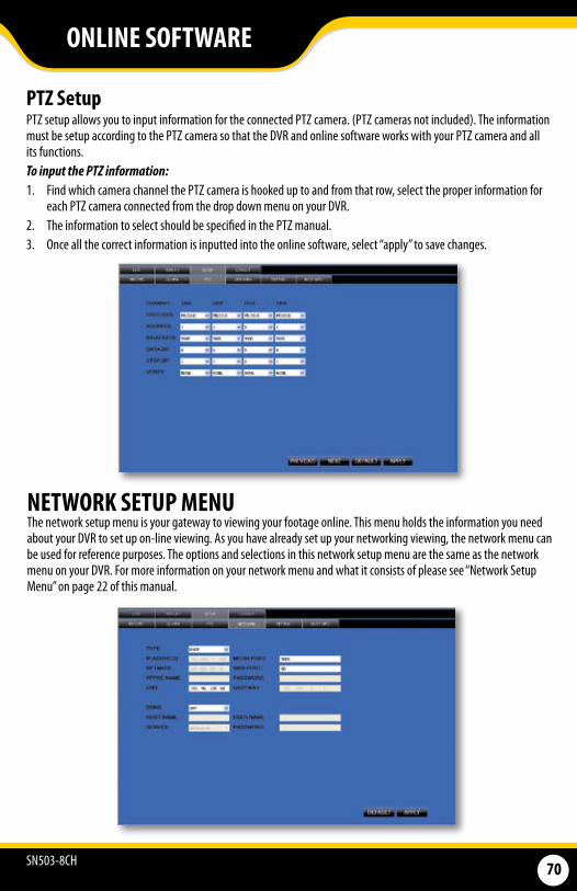
SN503-8CH 70
PTZ SetupPTZ setup allows you to input information for the connected PTZ camera. (PTZ cameras not included). The information must be setup according to the PTZ camera so that the DVR and online software works with your PTZ camera and all its functions. To input the PTZ information:1. Find which camera channel the PTZ camera is hooked up to and from that row, select the proper information for
each PTZ camera connected from the drop down menu on your DVR. 2. The information to select should be specified in the PTZ manual. 3. Once all the correct information is inputted into the online software, select “apply” to save changes.
NETWORK SETUP MENUThe network setup menu is your gateway to viewing your footage online. This menu holds the information you need about your DVR to set up on-line viewing. As you have already set up your networking viewing, the network menu can be used for reference purposes. The options and selections in this network setup menu are the same as the network menu on your DVR. For more information on your network menu and what it consists of please see “Network Setup Menu” on page 22 of this manual.
ONLINE SOFTWARE
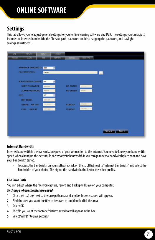
SN503-8CH 71
Settings This tab allows you to adjust general settings for your online viewing software and DVR. The settings you can adjust include the Internet bandwidth, the file save path, password enable, changing the password, and daylight savings adjustment.
Internet Bandwidth Internet bandwidth is the transmission speed of your connection to the Internet. You need to know your bandwidth speed when changing this setting. To see what your bandwidth is you can go to www.bandwidthplace.com and have your bandwidth tested.
• To adjust the bandwidth on your software, click on the scroll list next to “Internet bandwidth” and select the bandwidth of your choice. The higher the bandwidth, the better the video quality.
File Save PathYou can adjust where the files you capture, record and backup will save on your computer. To change where the files are saved: 1. Click the (…) box next to the save path area and a folder browse screen will appear. 2. Find the area you want the files to be saved to and double click the area. 3. Select OK. 4. The file you want the footage/pictures saved to will appear in the box. 5. Select “APPLY” to save settings.
ONLINE SOFTWARE

SN503-8CH 72
Password Setup This menu selection allows you to enable password protection as well as set a new password for the user and admin accounts on your DVR.
To enable password protection: 1. Select the scroll bar next to “password enable” and list will appear.2. Select to turn the password enable to “on”. 3. Select “apply”, to save your changes.
To change the password You have the option to change the password for user and admin, a user will only be able to access the search menu to view saved footage, where admin will be able to access anything in the menu. Both default passwords are 1234561. Make sure password enable is set to ON. 2. Select the • • • • • box next to the password you would like to change and a keyboard will appear. 3. Type the password you would like then select enter to close the keyboard.4. Type in the same password again next to “confirm” to confirm the password then select enter to close
the keyboard. 5. Once you have input the passwords to your liking, select “apply”, to save your changes.
DST DST stands for daylight saving time; you can adjust the DVR to change its time for you when daylight saving time approaches, so you don’t have to go back and do it yourself. You can also customize when the DVR changes for DST.
To turn the DVR daylight saving time on: 1. Select the scroll bar next to DST and list will appear.2. Select “on” to turn the DST on. 3. Select “apply”, to save your changes.
To set the DVR to adjust for daylight saving time on its own: 1. Select the scroll bar next to DST and list will appear.2. Highlight default and press select to turn the automatic DST adjustment on. 3. Select “apply”, to save your changes.
To customize the DVR’s daylight saving time adjustment:1. Select the scroll bar next to DST mode and list will appear.2. Select custom and a custom list will appear. 3. Adjust the time you want the clock to go back an hour by adjusting the week and month next to “start time”. 4. Adjust the time you want the clock to go forward an hour by adjusting the week and month next to “end time”. 5. To adjust the week and month, use the drop down list, highlight the week and/or month you want and
press select. 6. Once everything has been adjusted to your liking, select “apply” to save your settings.
ONLINE SOFTWARE
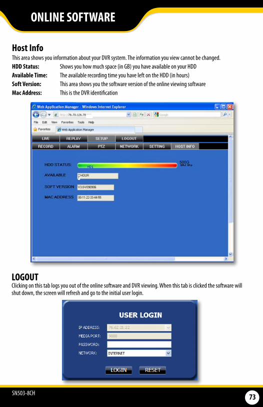
SN503-8CH 73
Host Info This area shows you information about your DVR system. The information you view cannot be changed. HDD Status: Shows you how much space (in GB) you have available on your HDD Available Time: The available recording time you have left on the HDD (in hours)Soft Version: This area shows you the software version of the online viewing softwareMac Address: This is the DVR identification
LOGOUT Clicking on this tab logs you out of the online software and DVR viewing. When this tab is clicked the software will shut down, the screen will refresh and go to the initial user login.
ONLINE SOFTWARE
500G
7
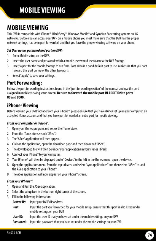
SN503-8CH 74
MOBILE VIEWING This DVR is compatible with iPhone®, BlackBerry®, Windows Mobile® and Symbian ®operating systems on 3G networks. Before you can access your DVR on a mobile phone you must make sure that the DVR has the proper network settings, has been port forwarded, and that you have the proper viewing software on your phone.
Set User name, password and port on DVR: 1. Go to Mobile setup on the DVR. 2. Insert the user name and password which a mobile user would use to access the DVR footage. 3. Insert a port for the mobile footage to run from. Port 1024 is a good default port to use. Make sure that you port
forward this port on top of the other two ports. 4. Select “apply” to save your settings.
Port Forwarding: Follow the port forwarding instructions found in the “port forwarding section” of the manual and use the port assigned in mobile viewing setup screen. Be sure to forward the mobile port IN ADDITION to ports 80 and 9000.
iPhone® Viewing Before viewing your DVR footage from your iPhone®, please ensure that you have iTunes set up on your computer, an activated iTunes account and that you have port forwarded an extra port for mobile viewing.
MOBILE VIEWING
From your iPhone®: 1. Open and Run the ASee application. 2. Select the setup icon in the bottom right corner of the screen. 3. Fill in the following information:
Server IP: Input your DVR’s IP address Port: Input the port you forwarded for your mobile setup. Ensure that this port is also listed under
mobile settings on your DVRUser ID: Input the user ID that you have set under the mobile settings on your DVRPassword: Input the password that you have set under the mobile settings on your DVR
From your computer or iPhone®:1. Open your iTunes program and access the iTunes store. 2. From the iTunes store, search “ASee”. 3. The “ASee” application will then appear. 4. Click on the application, open the download page and then download “ASee”. 5. The downloaded file will then be under your applications in your iTunes library. 6. Connect your iPhone® to your computer. 7. Your iPhone® will then be displayed under “Devices” to the left in the iTunes menu, open the device. 8. Open the applications menu from the top tab area and select “sync applications” and then select “ASee” to add
the ASee application to your iPhone®. 9. The ASee application will now appear on your iPhone® screen.
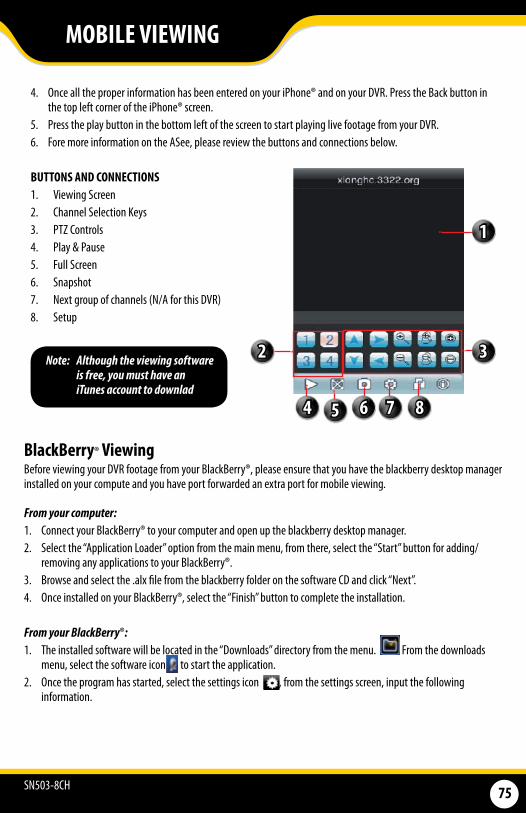
SN503-8CH 75
BUTTONS AND CONNECTIONS1. Viewing Screen2. Channel Selection Keys3. PTZ Controls4. Play & Pause5. Full Screen6. Snapshot7. Next group of channels (N/A for this DVR)8. Setup
4. Once all the proper information has been entered on your iPhone® and on your DVR. Press the Back button in the top left corner of the iPhone® screen.
5. Press the play button in the bottom left of the screen to start playing live footage from your DVR. 6. Fore more information on the ASee, please review the buttons and connections below.
BlackBerry® Viewing Before viewing your DVR footage from your BlackBerry®, please ensure that you have the blackberry desktop manager installed on your compute and you have port forwarded an extra port for mobile viewing.
From your computer:1. Connect your BlackBerry® to your computer and open up the blackberry desktop manager. 2. Select the “Application Loader” option from the main menu, from there, select the “Start” button for adding/
removing any applications to your BlackBerry®. 3. Browse and select the .alx file from the blackberry folder on the software CD and click “Next”. 4. Once installed on your BlackBerry®, select the “Finish” button to complete the installation.
From your BlackBerry®: 1. The installed software will be located in the “Downloads” directory from the menu. From the downloads
menu, select the software icon to start the application.2. Once the program has started, select the settings icon , from the settings screen, input the following
information.
MOBILE VIEWING
1
3
4 5 6 7 8
2Note: Although the viewing software is free, you must have an iTunes account to downlad
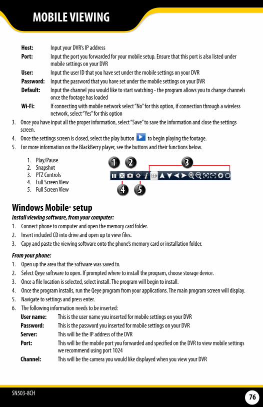
SN503-8CH 76
From your phone: 1. Open up the area that the software was saved to.2. Select Qeye software to open. If prompted where to install the program, choose storage device. 3. Once a file location is selected, select install. The program will begin to install. 4. Once the program installs, run the Qeye program from your applications. The main program screen will display. 5. Navigate to settings and press enter.6. The following information needs to be inserted:
User name: This is the user name you inserted for mobile settings on your DVRPassword: This is the password you inserted for mobile settings on your DVRServer: This will be the IP address of the DVRPort: This will be the mobile port you forwarded and specified on the DVR to view mobile settings
we recommend using port 1024Channel: This will be the camera you would like displayed when you view your DVR
Windows Mobile® setup Install viewing software, from your computer: 1. Connect phone to computer and open the memory card folder. 2. Insert included CD into drive and open up to view files. 3. Copy and paste the viewing software onto the phone’s memory card or installation folder.
Host: Input your DVR’s IP address Port: Input the port you forwarded for your mobile setup. Ensure that this port is also listed under
mobile settings on your DVRUser: Input the user ID that you have set under the mobile settings on your DVRPassword: Input the password that you have set under the mobile settings on your DVR Default: Input the channel you would like to start watching - the program allows you to change channels
once the footage has loadedWi-Fi: If connecting with mobile network select “No” for this option, if connection through a wireless
network, select “Yes” for this option 3. Once you have input all the proper information, select “Save” to save the information and close the settings
screen.4. Once the settings screen is closed, select the play button to begin playing the footage. 5. For more information on the BlackBerry player, see the buttons and their functions below.
1. Play/Pause2. Snapshot3. PTZ Controls4. Full Screen View5. Full Screen View
MOBILE VIEWING
1 2 3
54

SN503-8CH 77
Symbian Mobile® From your computer:1. Connect phone to computer and open the memory card or installation folder. 2. Insert included CD into drive and open up to view files. 3. Copy and paste the viewing software onto the phone’s memory card folder.
From your mobile phone: 1. Open the file location, and open up the QQeye.sis file. Note: Directions may vary on the type of phone that is
being used. Refer to your phone instruction manual on how to access files from your mobile device.2. The phone will begin preparation to install.3. Once preparation is complete, the phone will request permission to install. Select “YES”. 4. You will then be prompted to choose where you want the file to install (Phone memory or card memory, you
can choose either location.) 5. Once you have selected where you would like to install the program, select “continue” and the program
will install. 6. Once the program has installed, go to applications and open the program. 7. Upon opening the program, you will be prompted to insert the following information:
Default access point: Choose the access point used to access the InternetServer address: Input the DVR’s External IP address in this sectionServer Port: Insert the set port for the Mobile connectionUser name: Insert the set user name, this was specified on the DVR, under mobile setupPassword: Insert the set password, this was specified with the user name, under mobile setup
on the DVRChannel: Select the channel you would like to view from the start up
8. Once all the proper information has been inserted select “Done” to save your settings and start viewing the mobile viewing software.
9. For a full screen view, select the footage being displayed.
MOBILE VIEWING
Note: Directions may vary depending on the type of phone that is being used. Refer to your phone’s instruction manual on how to access files from your mobile device.
7. Once the correct information has been inserted, select “OK” and a separate screen viewing your selected channel will appear.
8. The mobile software allows you to change channels, control a PTZ camera as well as capture a video. 9. If you capture a picture it will be stored in the same file location the program was installed. 10. You can convert normal display to full screen display by clicking the screen from on mobile device.
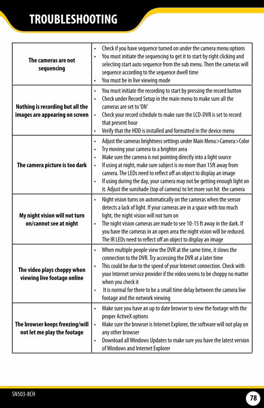
SN503-8CH 78
The cameras are not sequencing
• Check if you have sequence turned on under the camera menu options • You must initiate the sequencing to get it to start by right clicking and
selecting start auto sequence from the sub menu. Then the cameras will sequence according to the sequence dwell time
• You must be in live viewing mode
Nothing is recording but all the images are appearing on screen
• You must initiate the recording to start by pressing the record button • Check under Record Setup in the main menu to make sure all the
cameras are set to ‘ON’ • Check your record schedule to make sure the LCD-DVR is set to record
that present hour • Verify that the HDD is installed and formatted in the device menu
The camera picture is too dark
• Adjust the cameras brightness settings under Main Menu>Camera>Color• Try moving your camera to a brighter area • Make sure the camera is not pointing directly into a light source • If using at night, make sure subject is no more than 15ft away from
camera. The LEDs need to reflect off an object to display an image • If using during the day, your camera may not be getting enough light on
it. Adjust the sunshade (top of camera) to let more sun hit the camera
My night vision will not turn on/cannot see at night
• Night vision turns on automatically on the cameras when the sensor detects a lack of light. If your cameras are in a space with too much light, the night vision will not turn on
• The night vision cameras are made to see 10-15 ft away in the dark. If you have the cameras in an open area the night vision will be reduced. The IR LEDs need to reflect off an object to display an image
The video plays choppy when viewing live footage online
• When multiple people view the DVR at the same time, it slows the connection to the DVR. Try accessing the DVR at a later time
• This could be due to the speed of your Internet connection. Check with your Internet service provider if the video seems to be choppy no matter when you check it
• It is normal for there to be a small time delay between the camera live footage and the network viewing
The browser keeps freezing/will not let me play the footage
• Make sure you have an up to date browser to view the footage with the proper ActiveX options
• Make sure the browser is Internet Explorer, the software will not play on any other browser
• Download all Windows Updates to make sure you have the latest version of Windows and Internet Explorer
TROUBLESHOOTING
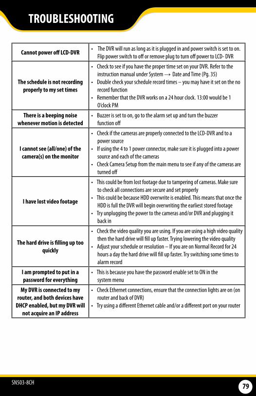
SN503-8CH 79
Cannot power off LCD-DVR • The DVR will run as long as it is plugged in and power switch is set to on. Flip power switch to off or remove plug to turn off power to LCD- DVR
The schedule is not recording properly to my set times
• Check to see if you have the proper time set on your DVR. Refer to the instruction manual under System → Date and Time (Pg. 35)
• Double check your schedule record times – you may have it set on the no record function
• Remember that the DVR works on a 24 hour clock. 13:00 would be 1 O’clock PM
There is a beeping noise whenever motion is detected
• Buzzer is set to on, go to the alarm set up and turn the buzzer function off
I cannot see (all/one) of the camera(s) on the monitor
• Check if the cameras are properly connected to the LCD-DVR and to a power source
• If using the 4 to 1 power connector, make sure it is plugged into a power source and each of the cameras
• Check Camera Setup from the main menu to see if any of the cameras are turned off
I have lost video footage
• This could be from lost footage due to tampering of cameras. Make sure to check all connections are secure and set properly
• This could be because HDD overwrite is enabled. This means that once the HDD is full the DVR will begin overwriting the earliest stored footage
• Try unplugging the power to the cameras and/or DVR and plugging it back in
The hard drive is filling up too quickly
• Check the video quality you are using. If you are using a high video quality then the hard drive will fill up faster. Trying lowering the video quality
• Adjust your schedule or resolution – If you are on Normal Record for 24 hours a day the hard drive will fill up faster. Try switching some times to alarm record
I am prompted to put in a password for everything
• This is because you have the password enable set to ON in the system menu
My DVR is connected to my router, and both devices have
DHCP enabled, but my DVR will not acquire an IP address
• Check Ethernet connections, ensure that the connection lights are on (on router and back of DVR)
• Try using a different Ethernet cable and/or a different port on your router
TROUBLESHOOTING
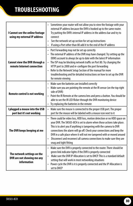
SN503-8CH 80
I Cannot see the online footage using my external IP address
• Sometimes your router will not allow you to view the footage with your external IP address because the DVR is hooked up to the same router. Try putting the DVR’s internal IP address in the address bar and try to connect
• See the network set up section for set up instructions • If using a Port other than 80 add it to the end of the IP address
Cannot view the DVR through a remote Internet connection
• Port Forwarding may not be set up correctly • The external IP address of the DVR may have changed. Try setting up the
DDNS account to always be up to date with the latest IP information • The ISP may be blocking network traffic on Port 80. Try changing the
HTTP port to 2000 and re-configure the port forwarding • Refer to the Network Setup Section of the manual for more
troubleshooting and for detailed instructions on how to set up the DVR for remote viewing
Remote control is not working
• Make sure the batteries are installed correctly • Make sure you are pointing the remote at the IR sensor (on the top right
side of DVR) • Point the IR Remote at the camera lens and press a button. You should be
able to see the IR LED flicker through the DVR monitoring device • Try replacing the batteries in the remote
I plugged a mouse into the USB port but it’s not working
• Make sure the mouse is connected to the proper USB port. The proper port for the mouse will be labeled with a mouse icon next to it
The DVR keeps beeping at me
• There could be video loss, HDD loss, motion detection or no HDD space on your DVR. The SN503-8CH is set to alarm when those actions take place. This is to alert you if anything is tampering with the camera to DVR connections the alarm will go off. Check your connections and keep the DVR in a safe place where it will not me tampered with or moved around
• Disconnect and reconnect all camera connections to make sure they are snug and tight fitting
The network settings on the DVR are not showing me any
information
• Make sure the DVR is properly connected to the router. There should be green link indicator lights if the DVR is properly connected
• Make sure the DVR IP Allocation is set to DHCP. This is a standard default setting that will work in most networking situations
• Power cycle the DVR is it is properly connected and the IP Allocation is set to DHCP
TROUBLESHOOTING
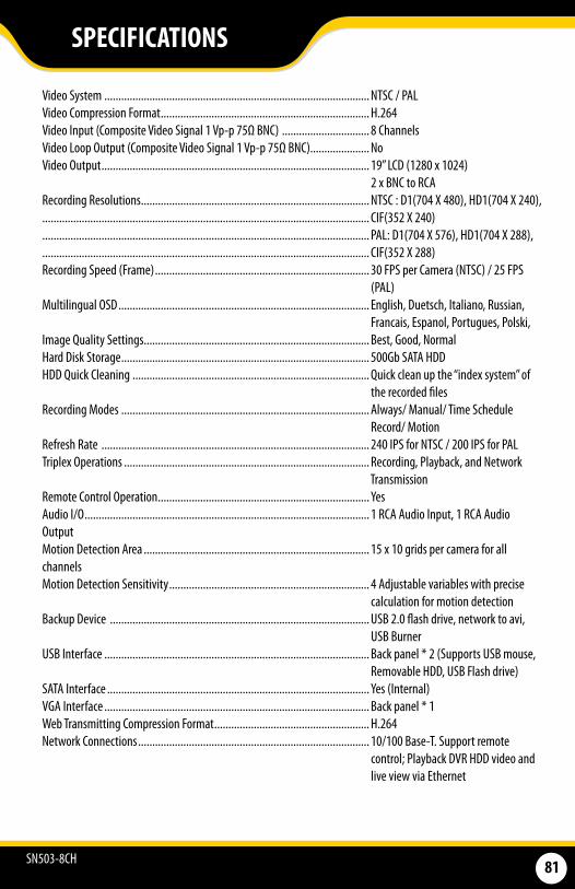
SN503-8CH 81
SPECIFICATIONS
Video System .............................................................................................. NTSC / PAL Video Compression Format .......................................................................... H.264Video Input (Composite Video Signal 1 Vp-p 75Ω BNC) ............................... 8 ChannelsVideo Loop Output (Composite Video Signal 1 Vp-p 75Ω BNC)..................... NoVideo Output ............................................................................................... 19” LCD (1280 x 1024) 2 x BNC to RCA Recording Resolutions ................................................................................. NTSC : D1(704 X 480), HD1(704 X 240),.................................................................................................................... CIF(352 X 240).................................................................................................................... PAL: D1(704 X 576), HD1(704 X 288), .................................................................................................................... CIF(352 X 288)Recording Speed (Frame) ............................................................................ 30 FPS per Camera (NTSC) / 25 FPS (PAL)Multilingual OSD ......................................................................................... English, Duetsch, Italiano, Russian, Francais, Espanol, Portugues, Polski, Image Quality Settings ................................................................................ Best, Good, NormalHard Disk Storage ........................................................................................ 500Gb SATA HDDHDD Quick Cleaning .................................................................................... Quick clean up the “index system” of the recorded filesRecording Modes ........................................................................................ Always/ Manual/ Time Schedule Record/ MotionRefresh Rate ............................................................................................... 240 IPS for NTSC / 200 IPS for PALTriplex Operations ....................................................................................... Recording, Playback, and Network TransmissionRemote Control Operation ........................................................................... YesAudio I/O ..................................................................................................... 1 RCA Audio Input, 1 RCA Audio OutputMotion Detection Area ................................................................................ 15 x 10 grids per camera for all channelsMotion Detection Sensitivity ....................................................................... 4 Adjustable variables with precise calculation for motion detectionBackup Device ............................................................................................ USB 2.0 flash drive, network to avi, USB BurnerUSB Interface .............................................................................................. Back panel * 2 (Supports USB mouse, Removable HDD, USB Flash drive)SATA Interface ............................................................................................. Yes (Internal)VGA Interface .............................................................................................. Back panel * 1Web Transmitting Compression Format ....................................................... H.264Network Connections .................................................................................. 10/100 Base-T. Support remote control; Playback DVR HDD video and live view via Ethernet
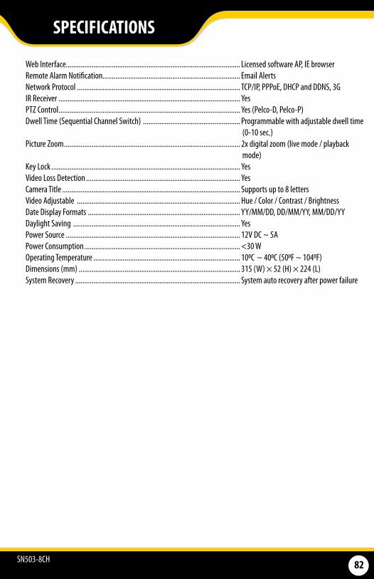
SN503-8CH 82
SPECIFICATIONS
Web Interface............................................................................................... Licensed software AP, IE browser Remote Alarm Notification ........................................................................... Email AlertsNetwork Protocol ......................................................................................... TCP/IP, PPPoE, DHCP and DDNS, 3GIR Receiver ................................................................................................... YesPTZ Control ................................................................................................... Yes (Pelco-D, Pelco-P)Dwell Time (Sequential Channel Switch) ..................................................... Programmable with adjustable dwell time (0-10 sec.)Picture Zoom ................................................................................................ 2x digital zoom (live mode / playback mode)Key Lock ....................................................................................................... YesVideo Loss Detection .................................................................................... YesCamera Title ................................................................................................. Supports up to 8 lettersVideo Adjustable ......................................................................................... Hue / Color / Contrast / BrightnessDate Display Formats ................................................................................... YY/MM/DD, DD/MM/YY, MM/DD/YYDaylight Saving ........................................................................................... YesPower Source ............................................................................................... 12V DC ~ 5APower Consumption ..................................................................................... <30 WOperating Temperature ................................................................................ 100C ~ 400C (500F ~ 1040F)Dimensions (mm) ........................................................................................ 315 (W) × 52 (H) × 224 (L)System Recovery .......................................................................................... System auto recovery after power failure
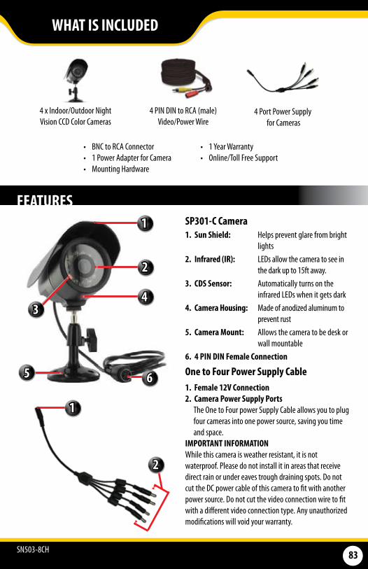
SN503-8CH 83
WHAT IS INCLUDED
FEATURES
4 x Indoor/Outdoor Night Vision CCD Color Cameras
4 PIN DIN to RCA (male) Video/Power Wire
• BNC to RCA Connector• 1 Power Adapter for Camera• Mounting Hardware
• 1 Year Warranty• Online/Toll Free Support
SP301-C Camera1. Sun Shield: Helps prevent glare from bright
lights2. Infrared (IR): LEDs allow the camera to see in
the dark up to 15ft away.3. CDS Sensor: Automatically turns on the
infrared LEDs when it gets dark4. Camera Housing: Made of anodized aluminum to
prevent rust5. Camera Mount: Allows the camera to be desk or
wall mountable6. 4 PIN DIN Female Connection
One to Four Power Supply Cable 1. Female 12V Connection 2. Camera Power Supply Ports The One to Four power Supply Cable allows you to plug four cameras into one power source, saving you time and space. IMPORTANT INFORMATIONWhile this camera is weather resistant, it is not waterproof. Please do not install it in areas that receive direct rain or under eaves trough draining spots. Do not cut the DC power cable of this camera to fit with another power source. Do not cut the video connection wire to fit with a different video connection type. Any unauthorized modifications will void your warranty.
4 Port Power Supply for Cameras
1
2
4
6
2
1
3
5
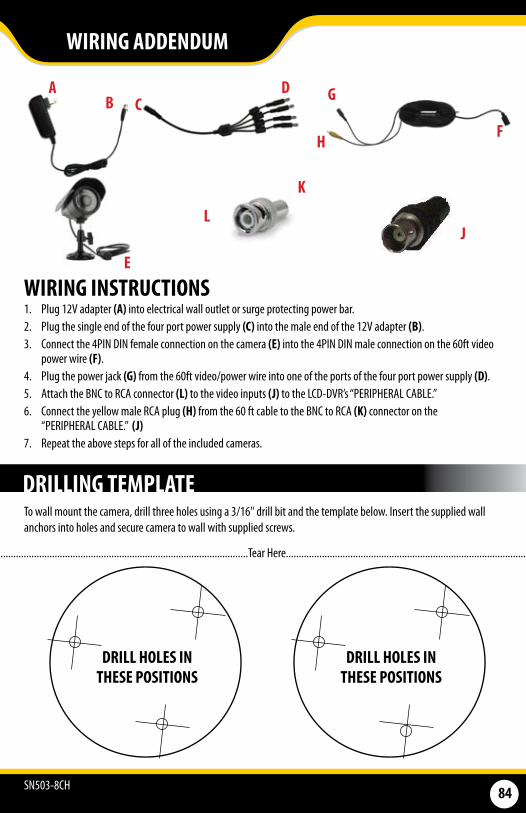
SN503-8CH 84
WIRING INSTRUCTIONS1. Plug 12V adapter (A) into electrical wall outlet or surge protecting power bar.2. Plug the single end of the four port power supply (C) into the male end of the 12V adapter (B).3. Connect the 4PIN DIN female connection on the camera (E) into the 4PIN DIN male connection on the 60ft video
power wire (F).4. Plug the power jack (G) from the 60ft video/power wire into one of the ports of the four port power supply (D).5. Attach the BNC to RCA connector (L) to the video inputs (J) to the LCD-DVR’s “PERIPHERAL CABLE.”6. Connect the yellow male RCA plug (H) from the 60 ft cable to the BNC to RCA (K) connector on the
“PERIPHERAL CABLE.” (J)7. Repeat the above steps for all of the included cameras.
AB C
D
HF
G
E
LJ
K
WIRING ADDENDUM
To wall mount the camera, drill three holes using a 3/16" drill bit and the template below. Insert the supplied wall anchors into holes and secure camera to wall with supplied screws.
DRILL HOLES IN THESE POSITIONS
DRILL HOLES IN THESE POSITIONS
DRILLING TEMPLATE
.......................................................................................................Tear Here.....................................................................................................
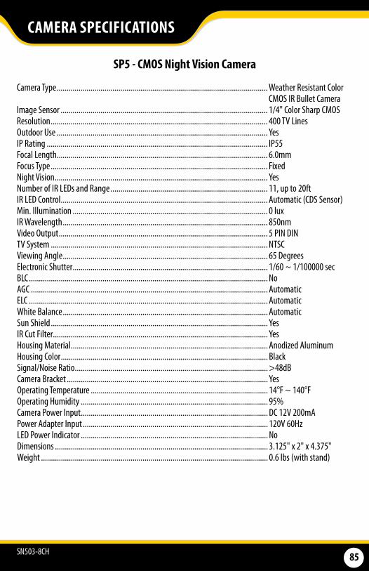
SN503-8CH 85
CAMERA SPECIFICATIONS
SP5 - CMOS Night Vision Camera
Camera Type .......................................................................................................... Weather Resistant Color CMOS IR Bullet Camera
Image Sensor ........................................................................................................ 1/4" Color Sharp CMOSResolution ............................................................................................................. 400 TV LinesOutdoor Use .......................................................................................................... YesIP Rating ............................................................................................................... IP55Focal Length.......................................................................................................... 6.0mmFocus Type ............................................................................................................. FixedNight Vision ........................................................................................................... YesNumber of IR LEDs and Range ............................................................................... 11, up to 20ftIR LED Control ........................................................................................................ Automatic (CDS Sensor)Min. Illumination .................................................................................................. 0 luxIR Wavelength ....................................................................................................... 850nmVideo Output ......................................................................................................... 5 PIN DIN TV System ............................................................................................................. NTSCViewing Angle ....................................................................................................... 65 DegreesElectronic Shutter .................................................................................................. 1/60 ~ 1/100000 secBLC ........................................................................................................................ No AGC ....................................................................................................................... AutomaticELC ........................................................................................................................ AutomaticWhite Balance ....................................................................................................... AutomaticSun Shield ............................................................................................................. YesIR Cut Filter............................................................................................................ YesHousing Material ................................................................................................... Anodized AluminumHousing Color ........................................................................................................ BlackSignal/Noise Ratio ................................................................................................. >48dBCamera Bracket ..................................................................................................... YesOperating Temperature ......................................................................................... 14°F ~ 140°FOperating Humidity .............................................................................................. 95%Camera Power Input .............................................................................................. DC 12V 200mAPower Adapter Input ............................................................................................. 120V 60HzLED Power Indicator .............................................................................................. NoDimensions ........................................................................................................... 3.125" x 2" x 4.375" Weight .................................................................................................................. 0.6 lbs (with stand)
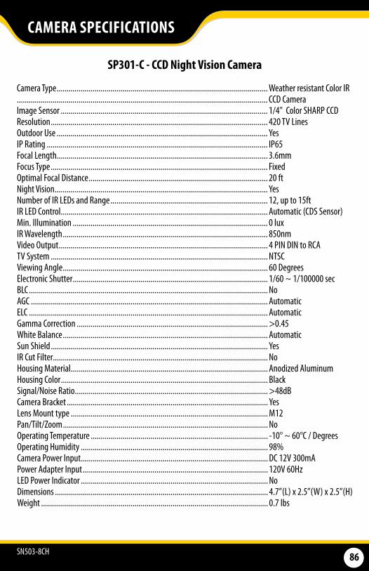
SN503-8CH 86
CAMERA SPECIFICATIONS
SP301-C - CCD Night Vision Camera
Camera Type .......................................................................................................... Weather resistant Color IR .............................................................................................................................. CCD CameraImage Sensor ........................................................................................................ 1/4" Color SHARP CCDResolution ............................................................................................................. 420 TV LinesOutdoor Use .......................................................................................................... YesIP Rating ............................................................................................................... IP65Focal Length.......................................................................................................... 3.6mmFocus Type ............................................................................................................. FixedOptimal Focal Distance .......................................................................................... 20 ftNight Vision ........................................................................................................... YesNumber of IR LEDs and Range ............................................................................... 12, up to 15ftIR LED Control ........................................................................................................ Automatic (CDS Sensor)Min. Illumination .................................................................................................. 0 luxIR Wavelength ....................................................................................................... 850nmVideo Output ......................................................................................................... 4 PIN DIN to RCATV System ............................................................................................................. NTSCViewing Angle ....................................................................................................... 60 DegreesElectronic Shutter .................................................................................................. 1/60 ~ 1/100000 secBLC ........................................................................................................................ NoAGC ....................................................................................................................... AutomaticELC ........................................................................................................................ AutomaticGamma Correction ................................................................................................ >0.45White Balance ....................................................................................................... AutomaticSun Shield ............................................................................................................. YesIR Cut Filter............................................................................................................ NoHousing Material ................................................................................................... Anodized AluminumHousing Color ........................................................................................................ Black Signal/Noise Ratio ................................................................................................. >48dBCamera Bracket ..................................................................................................... YesLens Mount type ................................................................................................... M12Pan/Tilt/Zoom ....................................................................................................... NoOperating Temperature ......................................................................................... -10° ~ 60°C / DegreesOperating Humidity .............................................................................................. 98%Camera Power Input .............................................................................................. DC 12V 300mAPower Adapter Input ............................................................................................. 120V 60HzLED Power Indicator .............................................................................................. NoDimensions ........................................................................................................... 4.7”(L) x 2.5”(W) x 2.5”(H)Weight .................................................................................................................. 0.7 lbs
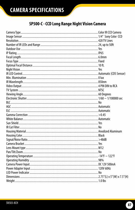
SN503-8CH 87
SP500-C - CCD Long Range Night Vision Camera
Camera Type .......................................................................................................... Color IR CCD CameraImage Sensor ........................................................................................................ 1/4" Sony Color CCDResolution ............................................................................................................. 420 TV LinesNumber of IR LEDs and Range ............................................................................... 24, up to 50ftOutdoor Use .......................................................................................................... YesIP Rating ............................................................................................................... IP65Focal Length.......................................................................................................... 6.0mmFocus Type ............................................................................................................. FixedOptimal Focal Distance .......................................................................................... 10 ft.Night Vision ........................................................................................................... YesIR LED Control ........................................................................................................ Automatic (CDS Sensor)Min. Illumination .................................................................................................. 0 luxIR Wavelength ....................................................................................................... 850nmVideo Output ......................................................................................................... 4 PIN DIN to RCA TV System ............................................................................................................. NTSCViewing Angle ....................................................................................................... 60 DegreesElectronic Shutter .................................................................................................. 1/60 ~ 1/100000 secBLC ........................................................................................................................ NoAGC ....................................................................................................................... AutomaticELC ........................................................................................................................ AutomaticGamma Correction ................................................................................................ >0.45White Balance ....................................................................................................... AutomaticSun Shield ............................................................................................................. YesIR Cut Filter............................................................................................................ NoHousing Material ................................................................................................... Anodized AluminumHousing Color ........................................................................................................ BlackSignal/Noise Ratio ................................................................................................. >48dBCamera Bracket ..................................................................................................... YesLens Mount type ................................................................................................... M12Pan/Tilt/Zoom ....................................................................................................... NoOperating Temperature ......................................................................................... -14°F ~ 122°FOperating Humidity .............................................................................................. 98%Camera Power Input .............................................................................................. DC 12V 500mAPower Adapter Input ............................................................................................. 120V 60HzLED Power Indicator .............................................................................................. NoDimensions ........................................................................................................... 2.75"(L) x 5"(W) x 7.5"(H)Weight .................................................................................................................. 1.0 lbs
CAMERA SPECIFICATIONS

SN503-8CH 88
Beforecontactingtechnicalsupport,pleasefollowthetroubleshootingtipsbelowforsolutionsto commonproblems.
No picture/signal
• Make sure your TV/monitor is on the correct video input channel. This is NOT channel 3. Common terms for this channel is INPUT, AV CHANNEL, LINE 1, LINE 2 and AUX. Please use your TV or VCR manual to correctly identify this channel
• If your camera is connected to a VCR/DVR, make sure that it is properly connected to your TV/monitor
• Check all connections to make sure they are secure and properly connected• Check your power supply to ensure that the camera is powered up• Cup your hands around the front of the camera and look at the LEDs. They
should be glowing red. If they are not, check the power supply
Picture is too bright
• Make sure your camera is not aimed at direct sunlight• Adjust the sunshade by sliding it forwards to block out excess light• Make sure nothing is obstructing the CDS sensor on the camera. If the CDS
sensor is blocked, night vision mode will be active and may produce extra light in your camera’s picture
• Move your camera to another location
Picture is too dark
• If using at night, make sure your camera’s subject is no more than 15ft away (may vary based on amount of ambient light available)
• If using during the day, your camera may not be getting enough light. Adjust the sunshade by sliding it backwards to let in more light
• Check the brightness and contrast settings on your TV/monitor• If your camera is connected to a VCR/DVR, check the brightness and contrast
settings on the VCR/DVR• Move your camera to another location
Night Vision is not working
• The night vision turns on automatically when light levels drop. Try the camera in a pitch black setting. The area that it is in may have too much light and may not activate the sensor
• Cup your hands around the front of the camera and look at the LEDs. They should be glowing red. If they are not, check the power supply
CAMERA TROUBLESHOOTING
Toll free telephone: 1.866.946.7828
Email: [email protected]
Online live web chat: Visit www.defender-usa.com
Toll free fax:1.888.771.1701

SN503-8CH 89
For more information on additional accessories, parts and much more, please visit:
www.defender-usa.com
If you accidentally damage or lose any parts they can be replaced with ease. The following are parts that came with your system and their reference model numbers so you can continue to effectively monitor your premises.
REPLACEMENT PARTS
ADDITIONAL ACCESSORIES
PRODUCT MODEL# DESCRIPTION
DF10WExtendtherangeofyourcameraswitha60ftextension.
SP301-CUpgradeyourcameratoahigherresolutionandadvancedUVfiltersforaccurateandvibrantcolours.
SP100-STAlertallpotentialcriminalsofyoursecurityandhelpdetercrimewithawindowsticker.
SGN100Alertallpotentialcriminalsofyoursecurityandhelpdetercrimewiththisdurablealuminumsign.
You may wish to add to your system and upgrade some components of it. Here are some items that can boost the effectiveness of your video security system.
PRODUCT MODEL# DESCRIPTION
DFW614PINDINCable
ACC-BNCBNCtoRCAConnector
ACC-SQUID-4TO1Four-to-OnePowerSupply
SOFTWARE/MANUALS
Yourproductsoftwareandmanualareavailablefordownloadat: http://www.defender-usa.com/downloads.php

DisclaimerDefender does not endorse the use of any Defender products for illegal activities. Defender is not responsible or liable in any way shape or form for any damage, vandalism, theft or any other action that may occur while a Defender product is in use by the consumer.
VISIT US ON THE WEB!► Product Information
►User Manuals
► Quick Start Guides
► Specification Sheets
► Software Updates
► Firmware Upgrades
www.defender-usa.com
SN503-8CHwww.defender-usa.com