instruction manual - abb group · pdf fileinstruction manual magnetic flowmeters 50cd9001...
TRANSCRIPT

INSTRUCTION MANUALMAGNETIC FLOWMETERS50CD9001
COMPACT DESIGN (CD1) ANALOG SIGNAL CONVERTER
PN24399A
ABB Instrumentation

The following are registered trademarks of ABB Automation Inc.:MAG-X®
MINI-MAG®
The following is a trademark of ABB Automation Inc.:COPA-X
The following is a trademark of E. I. DuPont de Nemours & Company:TEFLON
WARNING notices as used in this manual apply to hazards or unsafe practices which could resultin personal injury or death.
CAUTION notices apply to hazards or unsafe practices which could result in property damage.
NOTES highlight procedures and contain information which assist the operator in understandingthe information contained in this manual.
All software, including design, appearance, algorithms and sourcecodes, is copyrighted and owned by ABB Automation Inc. or its
suppliers.
WARNINGPOSSIBLE PROCESS UPSETS
Maintenance must be performed only by qualified personnel and onlyafter securing equipment controlled by this product. Adjusting or
removing this product while it is in the system may upset the processbeing controlled. Some process upsets may cause injury or damage.
NOTICEThe information contained in this document is subject to change without
notice.
ABB Automation Inc., its affiliates, employees, and agents, and theauthors of and contributors to this publication specifically disclaim allliabilities and warranties, express and implied (including warranties ofmerchantability and fitness for a particular purpose), for the accuracy,currency, completeness, and/or reliability of the information contained
herein and/or for the fitness for any particular use and/or for theperformance of any material and/or equipment selected in whole or part
with the user of/or in reliance upon information contained herein.Selection of materials and/or equipment is at the sole risk of the user of
this publication.
This document contains proprietary information of ABB Automation Inc.,and is issued in strict confidence. Its use, or reproduction for use, forthe reverse engineering, development or manufacture of hardware or
software described herein is prohibited. No part of this document maybe photocopied or reproduced without the prior written consent of ABB
Automation Inc.
Copyright 1999 ABB Automation Inc. [December 1999]

TABLE OF CONTENTS
SAFETY SUMMARY . . . . . . . . . . . . . . . . . . . . . . . . . . . . . . . . . . . . . . . . . . . . . . . . . . . . . I
READ FIRST . . . . . . . . . . . . . . . . . . . . . . . . . . . . . . . . . . . . . . . . . . . . . . . . . . . . . . . . . . III
1.0 INTRODUCTION . . . . . . . . . . . . . . . . . . . . . . . . . . . . . . . . . . . . . . . . . . . . . . . . . . 1-1
1.1 General Description . . . . . . . . . . . . . . . . . . . . . . . . . . . . . . . . . . . . . . . . . . . . . . . . . . . . . . . . . . . . . . 1-11.2 Specifications . . . . . . . . . . . . . . . . . . . . . . . . . . . . . . . . . . . . . . . . . . . . . . . . . . . . . . . . . . . . . . . . . . . 1-4
2.0 INSTALLATION . . . . . . . . . . . . . . . . . . . . . . . . . . . . . . . . . . . . . . . . . . . . . . . . . . . 2-1
2.1 Inspection . . . . . . . . . . . . . . . . . . . . . . . . . . . . . . . . . . . . . . . . . . . . . . . . . . . . . . . . . . . . . . . . . . . . . . 2-12.2 Location and Mounting . . . . . . . . . . . . . . . . . . . . . . . . . . . . . . . . . . . . . . . . . . . . . . . . . . . . . . . . . . . . 2-22.3 Electrical Interconnections . . . . . . . . . . . . . . . . . . . . . . . . . . . . . . . . . . . . . . . . . . . . . . . . . . . . . . . . . 2-4
2.3.1 General . . . . . . . . . . . . . . . . . . . . . . . . . . . . . . . . . . . . . . . . . . . . . . . . . . . . . . . . . . . . . . . . . . 2-42.3.2 Integrally Mounted Signal Converter . . . . . . . . . . . . . . . . . . . . . . . . . . . . . . . . . . . . . . . . . . . 2-42.3.3 System With Remote Mounted Signal Converter . . . . . . . . . . . . . . . . . . . . . . . . . . . . . . . . . . 2-7
3.0 START-UP AND OPERATION . . . . . . . . . . . . . . . . . . . . . . . . . . . . . . . . . . . . . . . 3-1
3.1 General . . . . . . . . . . . . . . . . . . . . . . . . . . . . . . . . . . . . . . . . . . . . . . . . . . . . . . . . . . . . . . . . . . . . . . . . 3-13.1.1 Introduction. . . . . . . . . . . . . . . . . . . . . . . . . . . . . . . . . . . . . . . . . . . . . . . . . . . . . . . . . . . . . . . 3-13.1.2 Placing System On Line . . . . . . . . . . . . . . . . . . . . . . . . . . . . . . . . . . . . . . . . . . . . . . . . . . . . . 3-1
3.2 Changing Flow Range . . . . . . . . . . . . . . . . . . . . . . . . . . . . . . . . . . . . . . . . . . . . . . . . . . . . . . . . . . . . 3-33.3 Changing Signal Converter Output. . . . . . . . . . . . . . . . . . . . . . . . . . . . . . . . . . . . . . . . . . . . . . . . . . . 3-53.4 Data Conversion . . . . . . . . . . . . . . . . . . . . . . . . . . . . . . . . . . . . . . . . . . . . . . . . . . . . . . . . . . . . . . . . . 3-6
3.4.1 Analog Current Output . . . . . . . . . . . . . . . . . . . . . . . . . . . . . . . . . . . . . . . . . . . . . . . . . . . . . . 3-63.4.2 Frequency Output . . . . . . . . . . . . . . . . . . . . . . . . . . . . . . . . . . . . . . . . . . . . . . . . . . . . . . . . . . 3-63.4.3 Scaler Board. . . . . . . . . . . . . . . . . . . . . . . . . . . . . . . . . . . . . . . . . . . . . . . . . . . . . . . . . . . . . . 3-8
3.4.3.1 General Discussion . . . . . . . . . . . . . . . . . . . . . . . . . . . . . . . . . . . . . . . . . . . . . . . . . . 3-83.4.3.2 Scaler Programming. . . . . . . . . . . . . . . . . . . . . . . . . . . . . . . . . . . . . . . . . . . . . . . . . . 3-8
4.0 CALIBRATION . . . . . . . . . . . . . . . . . . . . . . . . . . . . . . . . . . . . . . . . . . . . . . . . . . . 4-1
4.1 General . . . . . . . . . . . . . . . . . . . . . . . . . . . . . . . . . . . . . . . . . . . . . . . . . . . . . . . . . . . . . . . . . . . . . . . . 4-14.1.1 Use of MAG-X Flow Signal Simulator (Model 55MC1019/1020) . . . . . . . . . . . . . . . . . . . . . . 4-24.1.2 Use of the EMF Flow Signal Simulator (Model 55XC2000) . . . . . . . . . . . . . . . . . . . . . . . . . . 4-3
4.2 Verifying Range Alignment . . . . . . . . . . . . . . . . . . . . . . . . . . . . . . . . . . . . . . . . . . . . . . . . . . . . . . . . . 4-44.3 Internal Calibration Check . . . . . . . . . . . . . . . . . . . . . . . . . . . . . . . . . . . . . . . . . . . . . . . . . . . . . . . . 4-10
5.0 CIRCUIT DESCRIPTION. . . . . . . . . . . . . . . . . . . . . . . . . . . . . . . . . . . . . . . . . . . . 5-1
5.1 Primary Signals. . . . . . . . . . . . . . . . . . . . . . . . . . . . . . . . . . . . . . . . . . . . . . . . . . . . . . . . . . . . . . . . . . 5-15.2 Signal Converter Assembly. . . . . . . . . . . . . . . . . . . . . . . . . . . . . . . . . . . . . . . . . . . . . . . . . . . . . . . . . 5-4
5.2.1 General Discussion. . . . . . . . . . . . . . . . . . . . . . . . . . . . . . . . . . . . . . . . . . . . . . . . . . . . . . . . . 5-45.2.2 Converter Board . . . . . . . . . . . . . . . . . . . . . . . . . . . . . . . . . . . . . . . . . . . . . . . . . . . . . . . . . . . 5-4
5.2.2.1 Differential Input Amplifier. . . . . . . . . . . . . . . . . . . . . . . . . . . . . . . . . . . . . . . . . . . . . . 5-45.2.2.2 Reference Amplifier . . . . . . . . . . . . . . . . . . . . . . . . . . . . . . . . . . . . . . . . . . . . . . . . . . 5-55.2.2.3 Range and Summing Circuits. . . . . . . . . . . . . . . . . . . . . . . . . . . . . . . . . . . . . . . . . . . 5-55.2.2.4 Error Amplifiers . . . . . . . . . . . . . . . . . . . . . . . . . . . . . . . . . . . . . . . . . . . . . . . . . . . . . . 5-65.2.2.5 Miller Amplifier and Comparator . . . . . . . . . . . . . . . . . . . . . . . . . . . . . . . . . . . . . . . . . 5-65.2.2.6 Low Flow Cutoff and Frequency Output . . . . . . . . . . . . . . . . . . . . . . . . . . . . . . . . . . . 5-65.2.2.7 Zero Return Feature . . . . . . . . . . . . . . . . . . . . . . . . . . . . . . . . . . . . . . . . . . . . . . . . . . 5-7
INSTRUCTION BULLETIN 50CD9001
i

5.3 Output Board . . . . . . . . . . . . . . . . . . . . . . . . . . . . . . . . . . . . . . . . . . . . . . . . . . . . . . . . . . . . . . . . . . . 5-85.3.1 AC Power Supplies . . . . . . . . . . . . . . . . . . . . . . . . . . . . . . . . . . . . . . . . . . . . . . . . . . . . . . . . 5-8
5.3.1.1 Magnet Driver Supply . . . . . . . . . . . . . . . . . . . . . . . . . . . . . . . . . . . . . . . . . . . . . . . . 5-85.3.1.2 Bipolar Analog Supply . . . . . . . . . . . . . . . . . . . . . . . . . . . . . . . . . . . . . . . . . . . . . . . . 5-85.3.1.3 Floating Supply (Current Output). . . . . . . . . . . . . . . . . . . . . . . . . . . . . . . . . . . . . . . . 5-8
5.3.2 DC Power Supplies . . . . . . . . . . . . . . . . . . . . . . . . . . . . . . . . . . . . . . . . . . . . . . . . . . . . . . . . 5-85.3.3 Magnet Driver . . . . . . . . . . . . . . . . . . . . . . . . . . . . . . . . . . . . . . . . . . . . . . . . . . . . . . . . . . . . 5-95.3.4 Current (or Frequency) Output Circuits . . . . . . . . . . . . . . . . . . . . . . . . . . . . . . . . . . . . . . . . . 5-9
5.4 Scaler Board . . . . . . . . . . . . . . . . . . . . . . . . . . . . . . . . . . . . . . . . . . . . . . . . . . . . . . . . . . . . . . . . . . . 5-115.4.1 Binary Counter and Coincidence Network. . . . . . . . . . . . . . . . . . . . . . . . . . . . . . . . . . . . . . . 5-115.4.2 Coincidence Detector and Reset Amplifier . . . . . . . . . . . . . . . . . . . . . . . . . . . . . . . . . . . . . . 5-115.4.3 Output Driver and Optical Coupler. . . . . . . . . . . . . . . . . . . . . . . . . . . . . . . . . . . . . . . . . . . . 5-12
6.0 MAINTENANCE . . . . . . . . . . . . . . . . . . . . . . . . . . . . . . . . . . . . . . . . . . . . . . . . . . . 6-1
6.1 General . . . . . . . . . . . . . . . . . . . . . . . . . . . . . . . . . . . . . . . . . . . . . . . . . . . . . . . . . . . . . . . . . . . . . . . 6-16.2 System Troubleshooting . . . . . . . . . . . . . . . . . . . . . . . . . . . . . . . . . . . . . . . . . . . . . . . . . . . . . . . . . . 6-26.3 Signal Converter Voltage Check (Static Test) . . . . . . . . . . . . . . . . . . . . . . . . . . . . . . . . . . . . . . . . . . 6-46.4 Signal Converter Servicing . . . . . . . . . . . . . . . . . . . . . . . . . . . . . . . . . . . . . . . . . . . . . . . . . . . . . . . . 6-66.5 Parts List . . . . . . . . . . . . . . . . . . . . . . . . . . . . . . . . . . . . . . . . . . . . . . . . . . . . . . . . . . . . . . . . . . . . . . 6-7
FIGURE LISTFIGURE 1-1. CONVERTER MOUNTING OPTIONS. . . . . . . . . . . . . . . . . . . . . . . . . . . . . . . . . . . . . . . . 1-2FIGURE 1-2.EXPLODED VIEW OF INTEGRAL SIGNAL CONVERTER WITH FLOW RATE DISPLAY 1-3FIGURE 2-1. OUTLINE DIMENSIONS, REMOTE MOUNTED SIGNAL CONVERTER . . . . . . . . . . . . . 2-3FIGURE 2-2. ELEMENTARY INTERCONNECTION DIAGRAM. . . . . . . . . . . . . . . . . . . . . . . . . . . . . . . 2-6FIGURE 2-3. MODEL 10D1465 COPA-X, 1/2" - 12" WITH REMOTE CONVERTER . . . . . . . . . . . . . . . 2-9FIGURE 2-4. MODEL 10D1465 COPA-X, 1/2" - 12" WITH INTEGRAL CONVERTER. . . . . . . . . . . . . 2-10FIGURE 2-5. MODEL 10D1465 COPA-X, 14" - 24" WITH REMOTE CONVERTER . . . . . . . . . . . . . . . 2-11FIGURE 2-6. MODEL 10D1465 COPA-X, 14" - 24" WITH INTEGRAL CONVERTER . . . . . . . . . . . . . 2-12FIGURE 2-7. MODEL 10D1475 MINI-MAG & 10D1476 K-MAG, WITH REMOTE CONVERTER . . . . 2-13FIGURE 2-8A. MODEL 10D1475 & 10D1476 WITH INTEGRAL CONVERTER (BEFORE JAN. 1999) 2-14FIGURE 2-8B. MODEL 10D1475 & 10D1476 WITH INTEGRAL CONVERTER (AFTER JAN. 1999) . 2-15FIGURE 2-9. MODEL 10D1477 CK-MAG WITH REMOTE OR INTEGRAL CONVERTER . . . . . . . . . 2-16FIGURE 2-10. INTERCONNECTION WIRING DIAGRAM; SCALER ASSEMBLY . . . . . . . . . . . . . . . . 2-18FIGURE 2-11. DETAIL: INTERCONNECTION CABLE & CONDUIT SEAL . . . . . . . . . . . . . . . . . . . . . 2-19FIGURE 2-12. OUTLINE DIMENSIONS, REMOTE MOUNTED SIGNAL CONVERTER . . . . . . . . . . . 2-20FIGURE 3-1. TYPICAL METER DATA TAG. . . . . . . . . . . . . . . . . . . . . . . . . . . . . . . . . . . . . . . . . . . . . . . 3-4FIGURE 3-2. TYPICAL SIGNAL CONVERTER NAMETAG . . . . . . . . . . . . . . . . . . . . . . . . . . . . . . . . . . 3-4FIGURE 4-1. TEST WIRING FOR MAG-X FLOW SIGNAL SIMULATOR. . . . . . . . . . . . . . . . . . . . . . . . 4-8FIGURE 4-2. TEST WIRING FOR EMF SIGNAL SIMULATOR. . . . . . . . . . . . . . . . . . . . . . . . . . . . . . . . 4-9FIGURE 5-1. FUNCTIONAL BLOCK DIAGRAM . . . . . . . . . . . . . . . . . . . . . . . . . . . . . . . . . . . . . . . . . . . 5-2FIGURE 5-2. WAVEFORM DIAGRAM . . . . . . . . . . . . . . . . . . . . . . . . . . . . . . . . . . . . . . . . . . . . . . . . . . 5-3FIGURE 5-3. DAMPING ADJUSTMENT . . . . . . . . . . . . . . . . . . . . . . . . . . . . . . . . . . . . . . . . . . . . . . . . 5-10FIGURE 6-1. LAYOUT, SIGNAL CONVERTER BOARD. . . . . . . . . . . . . . . . . . . . . . . . . . . . . . . . . . . . . 6-9FIGURE 6-2. LAYOUT, OUTPUT BOARD. . . . . . . . . . . . . . . . . . . . . . . . . . . . . . . . . . . . . . . . . . . . . . . . 6-9FIGURE 6-3. LAYOUT, SCALER ASSEMBLY (OPTION) . . . . . . . . . . . . . . . . . . . . . . . . . . . . . . . . . . . 6-10FIGURE 6-4. SCHEMATIC DIAGRAM, SCALER BOARD (OPTION). . . . . . . . . . . . . . . . . . . . . . . . . . . 6-11FIGURE 6-5. EXPLODED VIEW, REMOTE MOUNTEDSIGNAL CONVERTER . . . . . . . . . . . . . . . . . 6-12FIGURE 6-6. LAYOUT, DC/AC INVERTER (OPTIONAL) . . . . . . . . . . . . . . . . . . . . . . . . . . . . . . . . . . . 6-13FIGURE 6-7. SCHEMATIC DIAGRAM, DC/AC INVERTER . . . . . . . . . . . . . . . . . . . . . . . . . . . . . . . . . 6-13FIGURE 6-8. SCHEMATIC DIAGRAM, BASE BOARD FOR REMOTE MOUNTED CONVERTER. . . 6-14
INSTRUCTION BULLETIN 50CD9001
ii

SAFETY SUMMARY
GENERALWARNINGS
POSSIBLE PROCESS UPSETSMaintenance must be performed only by qualified personnel andonly after securing equipment controlled by this product. Adjustingor removing this product while it is in the system may upset theprocess being controlled. Some process upsets may cause injury ordamage.
RETURN OF EQUIPMENTAll Flowmeters and/or Signal Converters being returned to ABBInstrumentation for repair must be free of any hazardous materials(acids, alkalis, solvents, etc.). A Material Safety Data Sheet (MSDS)for all process liquids must accompany returned equipment. Con-tact ABB Instrumentation for authorization prior to returning equip-ment.
INSTRUCTION MANUALSDo not install, maintain or operate this equipment without reading,understanding and following the proper ABB Instrumentation in-structions and manuals, otherwise injury or damage may result.
ELECTRICAL SHOCK HAZARDEquipment powered by AC line voltage presents a potential electricshock hazard to the user. Make certain that the system power isdisconnected from the operating branch circuit before attemptingelectrical interconnections or service.
SPECIFICWARNINGS
All flowmeters and/or signal converters being returned to ABB In-strumentation for repair must be free of any hazardous materials(acids, alkalis, solvents, etc). A Material Safety Data Sheet (MSDS)for all process liquids must accompany returned equipment. Con-tact ABB Instrumentation for authorization prior to returning equip-ment. (pg. V, 6-1)
Equipment powered by ac line voltage constitutes a potential elec-tric shock hazard. Servicing of the Signal Converter should only beattempted by a qualified electronics technician. Make certain thatthe power input leads are disconnected from the operating branchcircuit before attempting electrical connections. (pg. 2-2, 2-7, 4-2,4-4, 6-2)
50CD9001 INSTRUCTION MANUAL
I

GÉNÉRAUXAVERTISSEMENTS
PROBLÈMES POTENTIELS. La maintenance doit être réaliséepar du personnel qualifié et seulement après avoir sécuriséles équipements contrôlés par ce produit. L’ajustement ou ledémontage de ce produit lorsqu’il est lié au système peutentraîner des dysfonctionnements dans le procédé qu’il con-trôle. Ces dysfonctionnements peuvent entraîner des bles-sures ou des dommages.
RETOUR D’ÉQUIPEMENT. Tout débitmètre et(ou) convert-isseur retourné à ABB Instrumentation pour réparation doitêtre exempt de toute trace de produit dangereux (acide, base,solvant, … ). Un certificat de sécurité matériel doit être jointpour tous les liquides utilisés dans le procédé. ContacterABB Instrumentation pour autorisation avant renvoi dumatériel.
MANUEL DE MISE EN ROUTE. Ne pas installer, maintenir ouutiliser cet équipement sans avoir lu, compris et suivi lesinstructions et manuels de ABB Instrumentation, dans le cascontraire il y a risque d’entraîner blessures ou dommages.
RISQUE DE CHOC ÉLECTRIQUELes équipements alimentés en courant alternatif constituentun risque de choc électrique potentiel pour l’utilisateur. As-surez-vous que les câbles d’alimentation amont sont décon-nectés avant de procéder à des branchements, des essais outests.
SPÉCIFIQUESAVERTISSEMENTS
Tout débitmètre et(ou) convertisseur retourné à ABB Instru-mentation pour réparation doit être exempt de toute trace deproduit dangereux (acide, base, solvant, … ). Un certificat desécurité matériel doit être joint pour tous les liquides utilisésdans le procédé. Contacter ABB Instrumentation pour autori-sation avant renvoi du matériel. (pg. V)
Les équipements alimentés en courant alternatif constituentun risque de choc électrique potentiel. La maintenance surdes équipements électromagnétiques ou des convertisseursdoit être effectuée par des techniciens qualifiés. Assurez-vous que les câbles d’alimentation amont sont déconnectésavant de procéder à des branchements, des essais ou tests.(pg. 2-2, 2-7, 4-2, 4-4, 6-2)
50CD9001 INSTRUCTION MANUAL
II

READ FIRST
WARNING
INSTRUCTION MANUALSDo not install, maintain, or operate this equipment without reading,
understanding and following the proper ABB Instrumentationinstructions and manuals, otherwise injury or damage may result.
RETURN OF EQUIPMENTAll Flowmeters and/or Signal Converters being returned to ABB
Instrumentation for repair must be free of any hazardous materials(acids, alkalis, solvents, etc). A Material Safety Data Sheet (MSDS) for all
process liquids must accompany returned equipment. Contact ABBInstrumentation for authorization prior to returning equipment.
NEMA 4X, Corrosion Resistant FinishThis product is painted with a high performance epoxy paint. The
corrosion protection provided by this finish is only effective if the finishis unbroken. It is the users’ responsibility to "touch-up" any damagethat has occurred to the finish during shipping or installation of the
product. Special attention must be given to: meter flange bolting, pipemounting of electronics, conduit entries and covers that are removed to
facilitate installation or repair. For continued corrosion protectionthroughout the product life, it is the users’ responsibility to maintain the
product finish. Incidental scratches and other finish damage must berepaired and promptly re-painted with approved touch-up paint. Provide
the model number and size of your product to the nearest ABBInstrumentation representative to obtain the correct touch-up paint.
Read these instructions before starting installation; save these instructions for future reference.
50CD9001 INSTRUCTION MANUAL
III

1.0 INTRODUCTION
1.1 General Description
The ABB Instrumentation Compact Design (CD1) Analog Signal Converter is designed for use withMAG-X® type Magnetic Flowmeters. The Signal Converter can be either integrally mounted as partof the Magnetic Flowmeter or mounted in a separate remote enclosure. Typical Signal Convertermounting arrangements are illustrated in Figure 1-1. Information regarding installation, operationand maintenance of the associated primary meter is provided in the Instruction Bulletin suppliedwith the particular Magnetic Flowmeter.
Remote mounting of the Signal Converter is recommended for one or all of the following conditions:
• process liquid temperature exceeds 175oF (80oC),
• ambient temperature is above 150oF (65oC),
• the specified vibration limit is exceeded (see Specifications 1.2).
The Analog Signal Converter includes the magnet driver unit that is used to power the meter’s mag-net coils. The process signal is developed by a sampling technique that utilizes the steady statemagnetic field principle (referred to as the MAG-X design concept). This provides optimum zeropoint stability with a magnet coil drive frequency of 3.75 Hz when 60 Hz line power is used.
The Converter can be supplied with either an analog current output signal (4-20 mA or 0-20 mA) ora 0-1 kHz pulse output signal, as specified at time-of-purchase. In addition, models supplied withthe integral Scaler option can provide either a 0-10 Hz or 0-10 kHz scaled output in the form of asolid state contact closure. Use of the Scaler permits conversion of the flow information to a directreading output signal in the measurement unit desired.
Flow rate indication can also be provided by inclusion of a 3-1/2 digit LCD readout device. Thisflow rate indicator derives its power from the 4-20 mA analog output signal. The analog current isconverted to a proportional voltage that is applied to a dual slope integrator. The full scale indica-tion is adjustable to make the resultant displayed data direct reading in either the desired engineer-ing unit or in percent. When this option is selected, a window is provided in the electronic housingcover to enable local data display as shown in Figure 1-2.
50CD9001 INSTRUCTION MANUAL
1-1

TYPICAL METER HOUSING WITHPRIMARY CMF BOARD
INTEGRALLY MOUNTED CONVERTER
REMOTE HOUSING WITH BASEBOARD
REMOTE MOUNTED CD1 CONVERTER
FIGURE 1-1. CONVERTER MOUNTING OPTIONS
50CD9001 INSTRUCTION MANUAL
1-2

FIGURE 1-2. EXPLODED VIEW OF INTEGRAL SIGNAL CONVERTERWITH FLOW RATE DISPLAY
50CD9001 INSTRUCTION MANUAL
1-3

1.2 Specifications
Power Requirements
Voltage (as specified) 110 V ac ± 10%120 V ac ± 10%220 V ac ±10% (not FM approved)240 V ac ±10% (not FM approved)
ac Line Frequency 50/60 Hz ±5%
Power Consumption 15 watts max
Electrical Characteristics
Process Signal ±130 to ±525 µV per m/s±40 to ± 160 µV per ft/s
Excitation Frequency 3-1/8 Hz at 50 Hz line3-3/4 Hz at 60 Hz line
Dynamic Input Imped-ance
greater than 1012 ohms
Common Mode Rejec-tion
ac > 70 dbdc ±10 V
Reference Voltage ±50 to ±200 mV peak, typical
Response & TimeRecovery
0-100% slew time less than 4 s;0-100% power off, empty pipe, or over range less than 20 s
Damping(nominal time con-stant)
Adjustable via jumper on Converter BoardPosition F = 4 sPosition M = 25 sPosition S = 95 sAdditional smoothing possible by changing capacitor C205on Output Board. See Circuit Description Section 5.0.
Full Scale Span Adjustable via Range Potentiometer, R16; Digital Resis-tance Meter required to change span (not direct reading)
Current Output Sig-nal (as specified)
Analog Current 4-20 mA or 0-20 mA into a 0-900 Ω load
Frequency 0-1000 Hz square wave into 150 Ω min to 700 Ω max load
50CD9001 INSTRUCTION MANUAL
1-4

Current Output plusScaled Frequency
Scaled FrequencyOutput
provided only when integral Scaler option specified
0-10 Hz max solid state dry contact, opto coupled, 50 ms pulse width, ex-ternally powered
0-10 kHz max solid state switch, opto coupled, 50 µs pulse width, exter-nally powered
Scaling Factor preset as required, any number between 1 and 65,535 via bi-nary weighted switches
Isolation input and output are fully isolated
Zero Flow Cutoff output signal drops to 0% when input goes below nominally1% fsc
RFI ProtectionIntegrally MountedConverter
equivalent to SAMA Class 2, a, b, c, 0.1% (10 V/m, 20 -1000 MHz)
Temperature Limits -40 to 150oF (-40 to 65oC) without display
Relative Humidity 10% to 90% non-condensing
Electrical Connection
Integrally MountedConverter
See Flowmeter specifications
Remote MountedConverter
(5) 1/2" NPT internally threaded conduit connections (2 sup-plied with 1/2" NPT pipe plugs); 30 ft (9 m) interconnectioncable with conduit seal provided with meter
Rate Indicator (Optional)
Digital Panel Meter 3-1/2-digit Liquid Crystal Display with process signal inter-face board
Decimal Point hardware programmable, 3 positions
Readout 0.5" (12.7 mm) high digits
Input Signal 4 to 20 mA dc, linear (driven by Signal Converter analog out-put)
Power Requirement voltage derived from 4 to 20 mA dc process signal (2.75 Vmax drop)
50CD9001 INSTRUCTION MANUAL
1-5

Input Span adjustable span, enables direct reading display in units de-sired
Operating Tempera-ture Limits
32 to 120oF (0oC to +50oC); display will not be damaged bytemperatures of -13 to +149oF (-25oC to +65oC), howeverreadability will be affected if operating temperature limits areexceeded
Physical Characteristics
Outline Dimensions
Integral Converter(mounted with pri-mary)
refer to applicable primary meter Instruction Bulletin
Remotely MountedConverter
refer to Figure 2-1
Enclosure Classifica-tion
Integral Converter(mounted with pri-mary)
refer to applicable primary meter Instruction Bulletin
Remotely MountedConverter
NEMA 4 (IEC 529 IP 56), weather-tight and dust-tight
FM Approvals
Integral Converter(mounted with pri-mary)
refer to applicable primary meter Instruction Bulletin
Remotely MountedConverter
Non-incendive for Class I, Div 2, Gp A, B, C & D Dust-Igni-tion Proof for Class II, Div 1, Gp E, F & G Suitable for ClassIII, Div 1 outdoor hazardous locations
Vibration Limit
Primary w/integralConverter
5 to 14 Hz, 0.10"; 14 to 200 Hz, 1 g
Remotely mountedConverter
<0.75g continuous (10 to 150 Hz)
Electronics Housing die cast aluminum, epoxy finish, 316 sst attachment screws,gasketed covers
50CD9001 INSTRUCTION MANUAL
1-6

2.0 INSTALLATION
2.1 Inspection
The Compact Design (CD1) Analog Signal Converter may be supplied as an integrally mountedpart of the Magnetic Flowmeter, or in a separate remote mounted enclosure such as that shown inthe outline dimension diagram of Figure 2-1. In either case, the Signal Converter is protected bythe rugged enclosure and is unlikely to suffer damage during transit. When the Signal Converter issupplied as an integrally mounted part of the primary meter, refer to the Installation Section of theMagnetic Flowmeter Instruction Bulletin to supplement this discussion.
The Magnetic Flowmeter and Analog Signal Converter are shipped in a heavy-duty container de-signed to provide adequate protection of the equipment during transit. The packaging is certifiedfor air shipment by the Container Testing Laboratory. An itemized list of the items included in theshipment is attached to the shipping container.
The equipment should be inspected immediately upon arrival for indications of damage that mayhave occurred during shipment. In most cases, a careful visual inspection is all that is required toestablish apparent damage. All claims of damage should be reported to the shipping agent in-volved for equipment shipped F.O.B. Warminster, PA, or to ABB Instrumentation Company forequipment shipped F.O.B. job site before installation is attempted. In the event damage is suchthat faulty operation is likely to result, this damage should be brought to the attention of ABB Instru-mentation Service Department before installation is attempted. Always refer to the complete instru-ment serial number and model number in all correspondence concerning the equipment supplied.
Following inspection of the shipment contents, it is suggested that all items be carefully replaced inthe shipping container for storage and/or transit to the installation site. The use of normal care inthe handling and installation of this equipment will contribute substantially to satisfactory systemperformance. Careful preplanning of piping and cable runs, placement of equipment, etc., will addsignificantly to system appearance as well as overall safety.
50CD9001 INSTRUCTION MANUAL
2-1

2.2 Location and Mounting
When the Signal Converter is supplied as an integral part of the primary, refer to the InstallationSection of the Instruction Bulletin supplied with the Magnetic Flowmeter for location and mountingrequirements.
The installation site for the remote mounted Signal Converter should be clean, well lighted and ade-quately ventilated. Also, consideration should be given to access requirements for repair and main-tenance of the equipment. The remote mounted enclosure is designed to meet NEMA 4 standardsand is suitable for indoor and outdoor installation in an environment that is within the temperature,humidity and vibration limits as given in Section 1.2 .
Mounting dimensions for the wall (flat vertical surface) mounted enclosure are provided in Figure2-1. The remote housing should be mounted in a vertical position with the 1/2" NPT conduit connec-tions on the bottom. All conduit entrances must be equipped with seals and unused entrances musthave pipe plugs installed. This is required to maintain the NEMA 4 rating. Mounting hardware forwall mounting is to be supplied by the user, as applicable.
An alternative mounting option permits the remote Converter housing to be mounted to a 2-inchhorizontal or vertical pipe. The pipe clamping brackets and mounting hardware are supplied byF&P. Insert the two 5/16-18 x 3-3/4" long bolts into the holes provided in the pipe mountingbracket. Orient the bracket as required for vertical or horizontal pipe. As shown in Figure 2-1, thispipe mounting bracket must be attached to the rear of the Converter enclosure. Four 1/4-20 x 1/2"long self- tapping screws are supplied with the pipe mounting kit for attaching the bracket. Tomount the Converter, place the housing with the attached bracket against the mounting pipe withthe pipe between the two 3-3/4" long bolts. While supporting the housing, install the pipe clamp-ing bracket, flat washers and hex nuts. Tighten the nuts alternately to maintain even pressure distri-bution across the clamping bracket. Check that the Converter housing is plumb before securing.
NOTEThe remote enclosure to be used with Model 10D1477 is shown
in Figure 2-12.
The installation site must be provided with a convenient source of instrument power, as designatedon the instrument data tag. Either 110,120, 220 or 240 V, 50/60 Hz power may be specified.
The housing covers are removable to facilitate access for installation and maintenance. For installa-tion it will be necessary to remove the cover from the customer junction box (see Figure 1-1) byloosening the two captive screws on the front of the cover. Replace cover when installation hasbeen completed.
WARNINGEquipment powered by ac line voltage constitutes a potential electric
shock hazard. Servicing of the Signal Converter should only beattempted by a qualified electronics technician. Make certain that thepower input leads are disconnected from the operating branch circuit
before attempting electrical connections.
50CD9001 INSTRUCTION MANUAL
2-2
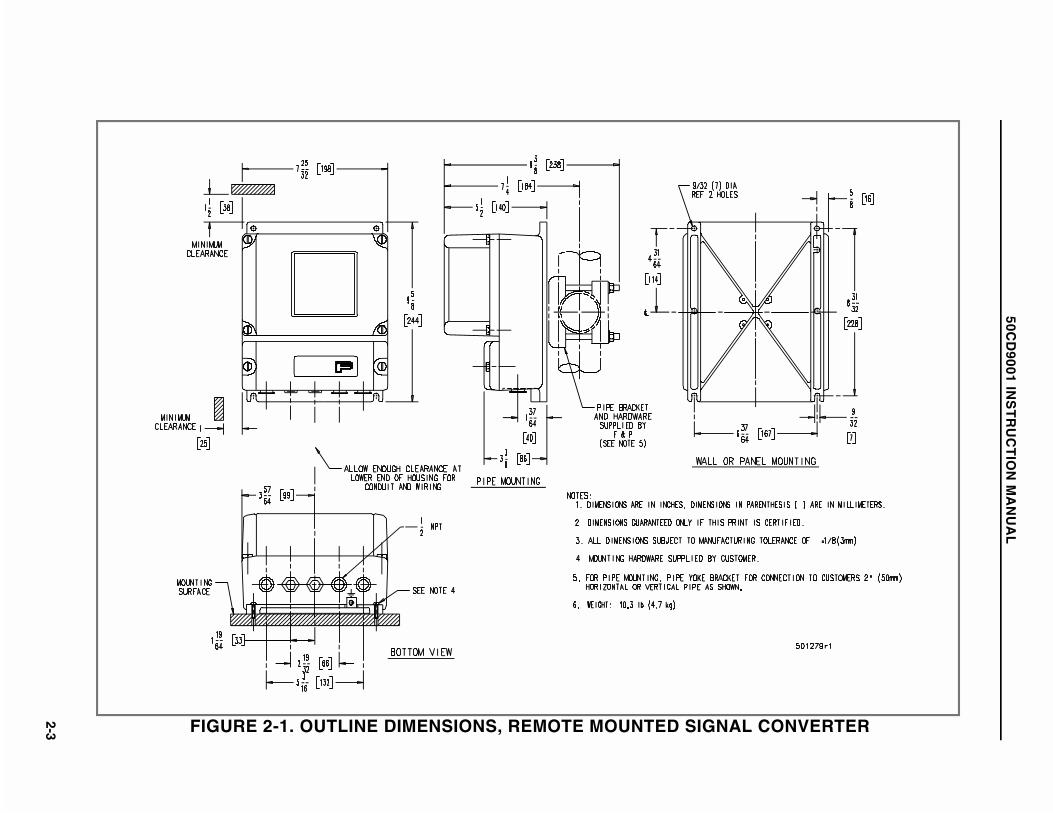
FIGURE 2-1. OUTLINE DIMENSIONS, REMOTE MOUNTED SIGNAL CONVERTER
50CD
9001 INS
TR
UC
TIO
N M
AN
UA
L
2-3

2.3 Electrical Interconnections
2.3.1 General
The elementary interconnection diagram for the Magnetic Flowmetering System is shown in Figure2-2 and will aid in supplementing the following discussion.
Refer to the applicable system electrical interconnection diagram for the particular Magnetic Flow-meter model and the associated integral or remote mounted CD1 Signal Converter for relevant sys-tem wiring. The diagrams are identified by meter model number and/or size and Converter option,as follows:
Figure 2-3 Model 10D1465 COPA-X, 1/2" - 12" W/Remote ConverterFigure 2-4 Model 10D1465 COPA-X, 1/2" - 12" W/Integral ConverterFigure 2-5 Model 10D1465 COPA-X, 14" - 24" W/Remote ConverterFigure 2-6 Model 10D1465 COPA-X, 14" - 24" W/Integral ConverterFigure 2-7 Model 10D1475 MINI-MAG & 10D1476 K-MAG, W/Remote ConverterFigure 2-8 Model 10D1475 MINI-MAG & 10D1476 K-MAG, W/Integral ConverterFigure 2-9 Model 10D1477 CK-MAG W/Remote or Integral Converter
For optimum performance of the Magnetic Flowmetering System it is important that the Flowmeterbe properly grounded. The appropriate grounding procedure is dependent upon the particular appli-cation as discussed in the Instruction Bulletin provided for the specific Magnetic Flowmeter.
The use of metal conduit provides physical protection and aids significantly in the reduction of in-duced RFI signals. For FM approved instruments used in nonhazardous locations, all wiring shallcomply with the national electrical code and local electrical code requirements. For FM approved in-struments used in hazardous locations, wiring must be in metal conduit. All boxes, fittings andseals are to comply with Articles 501, 502 or 503, as applicable, of ANSI/NFPA 70 and local electri-cal code requirements. FM requires that equipment not furnished by F&P be located in a nonhaz-ardous area unless it is approved for service in Division 1 or 2 locations.
2.3.1.1 Ultrasonic Cleaning (Option . . . not FM Approved)Ultrasonic transducers can be supplied for electrode cleaning with certain COPA-X Magnetic Flow-meters (2" and larger sizes). When this option is specified, a special junction box is mounted onthe side of the meter housing for ultrasonic interconnections. Applicable interconnection wiring forthe Ultrasonic Generator is discussed in Instruction Bulletin 55UC2000.
2.3.2 Integrally Mounted Signal Converter
I/O signals, ground and power interconnection wiring enters the junction box on the Magnetic Flow-meter housing via two 1/2" NPT conduit fittings. All external interconnection wiring is to be en-closed within metal conduit (supplied by the user). The signal and power wiring is terminated atterminal blocks located within the meter junction box. Generally, the right side of the meter junctionbox is used for power input and the left side for output signals and/or the zero return feature (seewiring diagram for remote Converter). Recommended procedure follows.
50CD9001 INSTRUCTION MANUAL
2-4
WARNINGEquipment powered by ac line voltage constitutes a potential electricshock hazard to the user. Make certain that the system power input
leads are disconnected from the operating branch circuit beforeattempting electrical interconnections.
1) Loosen the two captive screws and remove the instrument’s junction box cover. The TBterminals accept a bared wire which enters the hole below the clamp screws; solid copperwire is recommended .When stranded wire is used, the wire end should be tinned with sol-der.
2) Connect the power supply (voltage specified on the meter data tag) to terminals L/L1and N/L2. For the ac power supply, the black wire should be the phase side of the line andconnected to terminal (L/L1); the neutral or white wire to terminal (N/L2). Equipment ground-ing is affected by connecting a green colored wire to the terminal cast into the junction box;the other end of this wire is returned to the protective ground at the source of supply.
For servicing and protection of the power line, the customer should install a disconnectswitch and suitably sized fuse or circuit breaker; maximum power consumption is 15 watts.
3) The analog current or frequency (pulse) output signal lines (depending upon the optionspecified) are the plus (+) and minus (-) terminals. Connect these terminals to like termi-nals on the receiving equipment; i.e., plus to plus and minus to minus. Only one signalground should be used. The output load must be within the range of values given on the In-terconnection Diagram.
4) If the zero return feature is to be used, connect terminals Z1 and Z2 to a pair of non-pow-ered field contacts. This contact pair shall close to indicate a no flow condition; e.g., theauxiliary contacts in the process supply pump motor starter close when the pump is shutoff, or the limit switch contacts close when the supply valve is closed.
5) When the optional Scaler Assembly is supplied, refer to Figure 2-10 for wiring options.
6) Replace all electrical box covers to complete the installation.
50CD9001 INSTRUCTION MANUAL
2-5

FIGURE 2-2. ELEMENTARY INTERCONNECTION DIAGRAM
50CD9001 INSTRUCTION MANUAL
2-6

2.3.3 System With Remote Mounted Signal Converter
Illustration B of Figure 2-2 shows the elementary interconnection diagram. Wiring between the Mag-netic Flowmeter and the Remote Mounted Signal Converter is by way of an interconnection cablefurnished by ABB Instrumentation Co.; a 30 foot cable is furnished. This wiring must be installed ina metal conduit. For distances less than this, the cable can be shortened. Do not cut the cable tooshort; allow at least 6-8" of wire in the meter’s junction box and the remote box.
WARNINGEquipment powered by ac line voltage constitutes a potential electric
shock hazard. Servicing of the Signal Converter should only beattempted by a qualified electronics technician. Make certain that thepower input leads are disconnected from the operating branch circuit
before attempting electrical connections.
1) At the flowmeter location, loosen the two corner captive screws and remove the junctionbox cover. Observe the terminal barrier strips and markers. These terminals will accept thebared conductor wire and shield of the interconnection cables. The wire enters the hole be-low the clamp screw on the terminal strip. Attach the interconnection cable to the junctionbox using the conduit seal as indicated in Figure 2-11.
2) The interconnection cable consists of four coaxial cables and a ground wire. Note thatthe (M1 & M2/M3) wires use the larger cable designated ’A’ (in the illustration) and is atype RG-58A/U coaxial cable; no cable substitution is allowable. The other three wires des-ignated B, C, & D are type RG 174/U coaxial cable. Cable D attaches to terminal 16 and itsshield to 3. Cables B & C attach to terminals 1 and 2 respectively; the shields terminateand are not attached at the flowmeter end of the cable. (Except Model 10D1477; see Notein step 5) and Figure 2-9, Remote Mounted Converter).
3) Replace the junction box cover to complete the wiring at the flowmeter location.
4) At the remote mounted Signal Converter location, remove the junction box cover of theConverter by loosening the two captive screws. Two 1/2" NPT pipe plugs are supplied inthe base of the enclosure. Unused holes must be plugged to maintain the NEMA 4 rating.
5) Feed the end of the interconnection cable through the conduit opening and attach theends to the appropriate terminals. Cables designated ’B & C’ connect to terminals 1 & 2.
NOTE, MODEL 10D1477 ONLY:The signal cable leads (1 and 2) have shields supplying power for primary
electronics which must be connected as follows: line 1 shield ---- to *V+ line 2 shield ---- to *V-
*These voltages originate in the internal power supply. The supply terminals are located on left side of Output Board (see Figure 6-2)
6) Connect the power supply (voltage specified on the meter data tag) to terminals L/L1and N/L2. For the ac power supply, the black wire should be the phase side of the lineand be connected to terminal (L/L1); the neutral or white wire to terminal (N/L2). Equipmentground is affected by connecting a protective ground wire to the terminal cast into the enclo-sure; the other end of this wire is returned to the protective ground at the source of supply.
50CD9001 INSTRUCTION MANUAL
2-7

For servicing and protection of the power line, the customer should install a SPST discon-nect switch and suitably sized fuse or circuit breaker; max power consumption for the Flow-meter & Signal Converter is 15 watts.
7) The analog, or frequency (pulse) output signal lines (depending upon the option speci-fied) are the plus (+) and minus (-) terminals. Connect these terminals to like terminals onthe receiving equipment; i.e., plus to plus and minus to minus. Only one signal groundshould be used. The output load should be within the value given under Specifications andon the Interconnection Diagram.
8) If the zero return feature is to be used, connect terminals G3/Z1 and 22/Z1 to a pair ofnon-powered field contacts. This contact pair shall close to indicate a no flow condition;e.g., the auxiliary contacts in the process supply pump motor starter close when the pumpis shut off or the limit switch contacts close when the supply valve is closed.
9) When the Scaler Assembly is supplied refer to Figure 2-10 for wiring options.
10) Replace the cover of the remote enclosure to complete the electrical interconnectionphase.
50CD9001 INSTRUCTION MANUAL
2-8

FIGURE 2-3. MODEL 10D1465 COPA-X, 1/2" - 12" SIZE, WITH REMOTE CONVERTER
50CD
9001 INS
TR
UC
TIO
N M
AN
UA
L
2-9

FIGURE 2-4. MODEL 10D1465 COPA-X, 1/2" - 12" WITH INTEGRAL CONVERTER
50CD
9001 INS
TR
UC
TIO
N M
AN
UA
L
2-10

FIGURE 2-5. MODEL 10D1465 COPA-X, 14" - 24" WITH REMOTE CONVERTER
50CD
9001 INS
TR
UC
TIO
N M
AN
UA
L
2-11

FIGURE 2-6. MODEL 10D1465 COPA-X, 14"- 24" WITH INTEGRAL CONVERTER
50CD
9001 INS
TR
UC
TIO
N M
AN
UA
L
2-12

FIGURE 2-7. MODEL 10D1475 MINI-MAG & 10D1476 K-MAG, WITH REMOTE CONVERTER
50CD
9001 INS
TR
UC
TIO
N M
AN
UA
L
2-13

FIGURE 2-8A. MODEL 10D1475 MINI-MAG AND 10D1476 K-MAG, WITH INTEGRAL CONVERTERPRIOR TO JANUARY, 1999 (Refer to Table 2-1 for additional wiring information)
50CD
9001 INS
TR
UC
TIO
N M
AN
UA
L
2-14

FIGURE 2-8B. MODEL 10D1475 MINI-MAG AND 10D1476 K-MAG, WITH INTEGRAL CONVERTERAFTER JANUARY, 1999 (Refer to Table 2-1 for additional wiring information)
50CD
9001 INS
TR
UC
TIO
N M
AN
UA
L
2-15

FIGURE 2-9. MODEL 10D1477 CK-MAG WITH REMOTEOR INTEGRAL CONVERTER
50CD9001 INSTRUCTION MANUAL
2-16

THE FOLLOWING INFORMATION SUPPLEMENTS OR SUPERSEDES INFORMATION CONTAINED IN THEFOLLOWING FIGURES SHOWN IN THIS INSTRUCTION BULLETIN:
FIGURE 2-8AFIGURE 2-8B
TABLE 2-1 below summarizes the terminal designations and function vs. model numbers.
TABLE 2-1. TERMINAL MARKINGS vs. MODEL NUMBER
MODEL
TERMINAL BLOCKS
TERMINALSTERMINALFUNCTION
10D1475E10D1476C
[with 50CD9001 Integral Analog
Converters] 22 G3 + - 11 9 L N
22/G3
+/-
11/9 (optional)
L/N
Zero return
a) 4-20 mA current outputb) 0 - 1 kHz square-wave output
Active or passive scaled pulse output (9 = signal common)
Signal Converter power input; either 110/120 VAC or220/240 VAC.
2-17
50CD
9001 INS
TR
UC
TIO
N M
AN
UA
L

FIGURE 2-10. INTERCONNECTION WIRING DIAGRAM;SCALER ASSEMBLY
50CD9001 INSTRUCTION MANUAL
2-18

FIGURE 2-11. DETAIL: INTERCONNECTION CABLEAND CONDUIT SEAL
50CD9001 INSTRUCTION MANUAL
2-19

FIGURE 2-12. OUTLINE DIMENSIONS, REMOTE MOUNTED SIGNALCONVERTER (Use Only With Model 10D1477, CK-MAG)
50CD9001 INSTRUCTION MANUAL
2-20

3.0 START-UP AND OPERATION
3.1 General
3.1.1 Introduction
The ABB Instrumentation Magnetic Flowmetering System (which includes the integral or remoteSignal Converter) is precision calibrated at the factory for the values stated on the instrument tag.If specific values were not specified, the meter is calibrated at some nominal maximum flow rateand for a 4-20 mA current output span. In either case, the calibration data is noted on the instru-ment data tag as shown in Figure 3-1.
There are no operating controls that require field adjustment unless the full scale range setting wasnot specified. If a change in the full scale range setting is required, refer to paragraph 3.2, Chang-ing Flow Range, that follows. If no change is required, the equipment is ready for operation as re-ceived.
Prior to initial system start up, verify that the meter is properly installed; check flow direction, wiringinterconnection and grounding as discussed in the Section 2.0. Particular attention should be paidto the meter grounding procedures; improper grounding will result in unsatisfactory performance.Refer to the Instruction Bulletin supplied with the Magnetic Flowmeter to supplement this discus-sion.
Start flow through the process piping system that includes the meter. Allow a nominal flow throughthe pipeline for several minutes to purge entrapped air. The pipe line must be full for accurate flowmeasurement..
3.1.2 Placing System On Line
1) Apply the ac power to the Magnetic Flowmeter or remote mounted Converter by closingthe external switch or circuit breaker; there are no switches inside of the equipment. Alsoenergize any auxiliary equipment associated with the flow metering system such as remoteanalog recorders, controllers or rate indicators.
2) Initiate process flow through the pipeline. Flow measurement and concurrent output sig-nal transmission will commence with flow through the meter.
3) The signal damping is factory set for 4 seconds, which is satisfactory for most opera-tions. Additional damping is available via jumper J4 on the Converter Board (top circuitboard) of the Signal Converter. If J4 is moved from the F position to the M position or S po-sition, the response time is changed to 25 s or 96 s respectively. It is possible to trim any ofthe referenced times by replacing the smoothing capacitor, C205, located on the OutputBoard (bottom circuit board) of the Signal Converter. This capacitor is soldered in place.The use and adjustment of damping and smoothing is discussed in Section 5.3.
50CD9001 INSTRUCTION MANUAL
3-1

4) The zero return feature is automatically operative if terminals Z1/22 and Z2/G3 are con-nected to a customer furnished field contact; if unconnected the feature is disabled. Thezero return feature provides a positive zero output signal immediately following the shut-down of a pipeline due to stopping a pump or closing a valve. Note that forward and re-verse surges may exist in a pipeline, causing a pulsing output signal that is undesirablesince there is no actual flow. If the pipeline empties, because of stopping a pump or closinga valve, the flowmeter electrodes lose contact with the fluid and the output signal may driveupscale because of residual noise. Although such random output signals may be toleratedin many applications, it would be unacceptable for billing or other processes dependentupon true total registry.
50CD9001 INSTRUCTION MANUAL
3-2

3.2 Changing Flow Range
The meter and Converter data tags (see Figures 3-1 and 3-2) show the full scale span setting forwhich the Range Adjustment potentiometer was factory set. The procedure to change the range ad-justment is given below. Prior to making any adjustments, the terms used and limitations should beunderstood.
The range adjustment is located on the Signal Converter. This adjustment may be set for eitheranalog current output or frequency output at a given full scale (100%) flow rate value. The settingis in the specified engineering unit, such as gpm, m3/h, etc.
Example:
1. A 150 mm (6") size meter with a 4-20 mA current output, calibrated for a 0-1800 gpmflow span -
100% fsc = 20 mA = 1800 gpm
2. The same meter with a 0-1 kHz output -
100% fsc = 1 kHz = 1800 gpm
Any 10:1 operating range can be selected for a given meter size within the stated minimum to maxi-mum capacity limits given in Table A under Specifications of the Magnetic Flowmeter instructionbulletin. To change the ’as supplied’ full scale setting to some other flow rate, obtain the CAL FAC-TOR from the factor tag attached to the electronic base of the magnetic flowmeter. The typical fac-tor tag (for a 6" size meter) would have a CAL FACTOR of 2684 gpm. Using this information andthe desired 100% fsc flow rate value, the new ’ohms’ setting for the "range adjustment" potentiome-ter may be calculated. Figure 1-1 shows the location of the range adjustment potentiometer, on theSignal Converter printed circuit board. A digital multimeter with +0.05% accuracy is required forthis adjustment.
Using the example below as a guide, proceed as follows to obtain a new setting:
Example: It is desired to change the full scale span from 0-1800 gpm to 0-2000 gpm.
1) With the metering system de-energized, remove the Signal Converter accesscover.
2) Calculate the required ’ohms’ setting for the range adjustment potentiometer(R16) as follows:
NOTEThe desired flow rate and the meter CAL FACTOR must be in the same
flow measurement units.
50CD9001 INSTRUCTION MANUAL
3-3

Ohms = 40,000 x flow at 100% CAL FACTOR
= 40,000 x 2000 gpm 2684 gpm
= 29,806
3) On the Signal Converter pc board, disconnect the J3 jumper (adjacent to R16)from test point TP4 which is identified.
4) With the power turned off (or common connected to TP3), connect the DigitalMultimeter between test points TP3 and TP4. With the Multimeter set for resis-tance, energize the Multimeter. Turn the range adjustment potentiometer (R16) to29,806 +15 ohms (use the actual value calculated in step 2). This value must bewithin +0.05%or± 3 ohms.
5) Disconnect the Digital Multimeter. Connect jumper J3 to test point TP4 and re-place the instrument access cover.
The flow metering system is now preset for the new full scale flow rate value. No recalibration ofthe analog current or frequency output signal is required. However, the new full scale flow ratevalue and the ohms value to which R16 potentiometer is now set should be recorded for future ref-erence.
NOTESignal Converter assemblies are directly interchangeable between meters.However, it will be necessary to preset the "range adjustment" potentiome-
ter for the full scale span setting.
FIGURE 3-1. TYPICAL METER DATA TAG
FIGURE 3-2. TYPICAL SIGNAL CONVERTER NAMETAG
50CD9001 INSTRUCTION MANUAL
3-4

3.3 Changing Signal Converter Output
As previously discussed the output signal of the Signal Converter may be either a current (4-20 mAor 0-20 mA) or a frequency (0-1 kHz). Changing the output from a current to a frequency, or viceversa, is possible by relocating jumpers on the Signal Converter assembly.
Certain output signal ranges can be changed without recalibrating the Signal Converter; i.e., thosewhere the span is not changed. The following can be changed without calibration:
4-20 mA to 0-1 kHz
0-1 kHz to 4-20 mA
The following output signal range changes require recalibration since the span is changed. Refer toSection 4.0 Calibration to supplement this discussion.
4-20 mA to 0-20 mA
0-20 mA to 4-20 mA
0-1 kHz to 0-20 mA
The jumper requirements for the particular output options available are listed in Table 3-1. The lo-cation of the jumpers are shown in the circuit board layout drawing in Section 6.0; see ConverterBoard, Output Board and Schematic (Figures 6-1, 6-2 and 6-9).
NOTEWhen interchanging Signal Converters for servicing, verify that jumper se-
lection is compatible with the desired output signal option.
50CD9001 INSTRUCTION MANUAL
3-5
3.4 Data Conversion
3.4.1 Analog Current Output
The analog current output signal (4-20 mA or 0-20 mA) is a linear function that varies in direct pro-portion to the volumetric flow rate through the meter. The maximum output current of 20 mA corre-sponds to the 100% full scale span setting and the minimum output (typically 4 mA) corresponds to0% scale value. However, the current output signal will be cut-off at 4 mA (0.004 A)whenever proc-ess flow drops to less than 1% of full scale.
The output signal at any metered output can be calculated as follows:
Iout = [ (Imax - Ibias) x % scale ]+ Ibias
Example: Assume a metered flow of 80% scale - calculate the output signal for a 4-20 mArange output.
Iout = [ (20 mA - 4 mA) x 0.80 ]+ 4 mA
Iout = (16 mA x 0.80 )+ 4 mA = 16.8 mA
The analog output signal can be converted to a voltage signal by selection of the appropri-ate range resistor by use of Ohm’s law
E = I x R
Example: A recorder requires a 1-5 V input signal that is being received from the flowmeteras a 4-20 mA signal. Calculate the resistor value required for this conversion.
R = Instrument Voltage Span (1-5 V dc) Signal Current Range (0.004 - 0.020 A)
R = 4 V dc = 250 Ω 0.016 A
A precision resistor, ±0.1%, 0.5 W may be used.
Using the previous examples, the voltage output for a 1-5 V signal range at 80% scale would be:
E = 0.0168 A x 250 Ω = 4.2 V dc
3.4.2 Frequency Output
The 0 to 1 kHz square wave output can be introduced to electronic digital receivers. As the outputfrequency is directly proportional to flow rate, the signal can be integrated for indication of totalflow or scaled for display of cumulative volume, etc. Typically, when the output frequency and100% full scale (fsc) flow rate are known, an effective meter calibration factor can be computed forconversion of the total count to total flow in engineering units such as cubic meters, gallons, etc.In the pulse mode, the current generator puts out approximately 35 mA. A load resistor placed
50CD9001 INSTRUCTION MANUAL
3-6
across the (+) and (-) terminals will produce a pulse voltage equal to ≈ 35 mA x RL. If load resis-tor RL = 300Ω , pulse voltage ≈ 0.035 A x 300Ω = 10.5 V.
For example, assuming the 100% full scale flow is 400 gal/min, then the effective pulse factor (K inpulses/gal) can be computed as shown below:
100% fsc = 1000 Hz = 400 gal/min
then,
K = f max x s/min fsc flow rate
= 1000 x 60 400
= 150 pulses/gal
NOTEThe time constant for unit conversion must be in the appropriate time unit;
e.g., gal/s use 1, gal/min use 60, gal/hr use 3600.
To convert this frequency signal for display of the cumulative volume processed:
Total Flow (in gal) = Total Count K
When applicable, refer to the technical literature provided for the auxiliary digital receiver for spe-cific scaling procedures pertaining to that equipment.
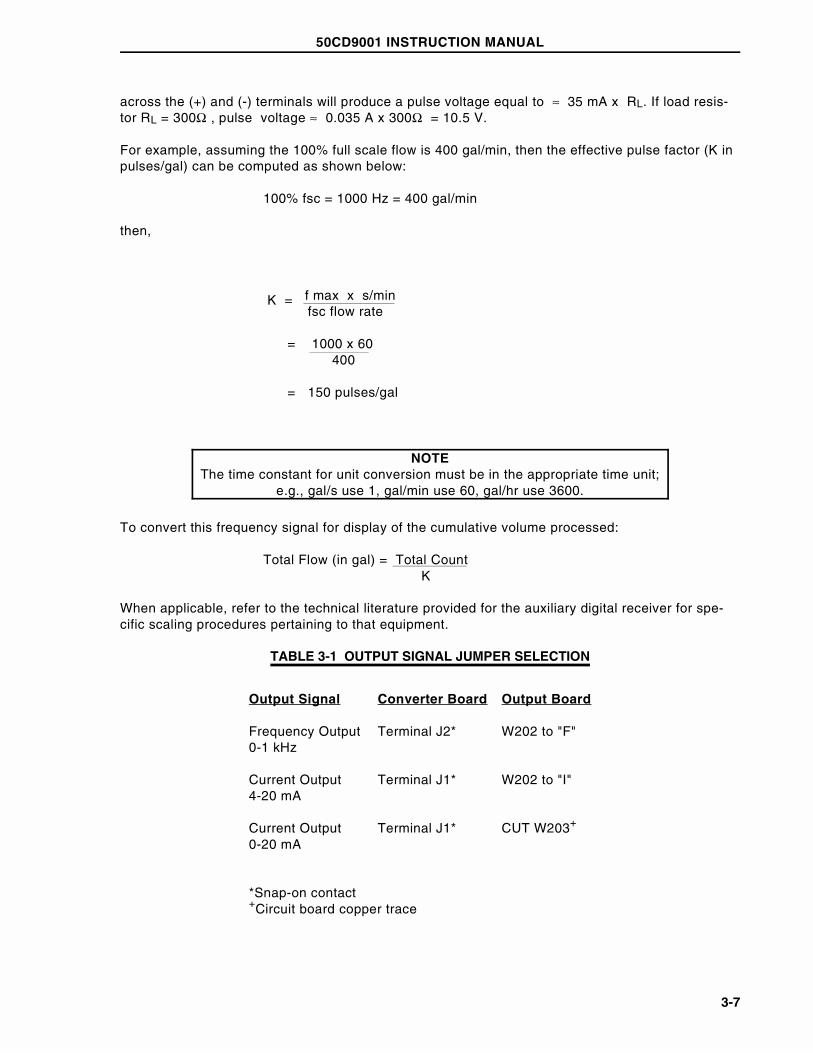
TABLE 3-1 OUTPUT SIGNAL JUMPER SELECTION
Output Signal Converter Board Output Board
Frequency Output0-1 kHz
Terminal J2* W202 to "F"
Current Output4-20 mA
Terminal J1* W202 to "I"
Current Output0-20 mA
Terminal J1* CUT W203+
*Snap-on contact+Circuit board copper trace
50CD9001 INSTRUCTION MANUAL
3-7

3.4.3 Scaler Board (Option)
3.4.3.1 General DiscussionAs discussed in paragraphs 3.4.1 and 3.4.2, above, either the analog current output signal or the 0-1 kHz pulse output signal can be selected for transmission to a remote receiver. Models suppliedwith the integral Scaler can provide either a 0-10 Hz or 0-10 kHz scaled output in the form of a con-tact closure. The optional Scaler assembly is driven by the 0-10 kHz signal applied to the Opto cou-pler, U202, on the Output Board (see Figure 6-2) when the Converter Board is set for analog signaloutput. Therefore the analog signal output can be used in conjunction with the scaled frequencyoutput, but the 0-1 kHz unscaled output signal is not available with the Scaler option. Use of theScaler permits conversion of the flow information to a direct reading signal in the measurement unitdesired.
0-10 Hz, 50 ms con-tact closure duration
Generally used to drive remote electromechanicalregisters, predetermining counters, etc.
0-10 kHz, 50 µs con-tact closure duration
The high frequency scaled output can be used toobtain a frequency ratio (fmax vs. fout) for use as aset point signal, or a direct reading signal for trans-mission to an electronic integrator or similar typedigital receiver.
3.4.3.2 Scaler Programming
3.4.3.2.1 Scaling FactorThe following procedure is applicable only for Signal Converters supplied with the optional Scalerassembly (see Model Numbering in meter Instruction Bulletin ). When the actual flow rate rangeand the desired measurement unit desired for the scaled output are supplied to ABB Instrumenta-tion, the Scaler can be factory programmed. In this case, the Scaler will not require programmingin the field unless one of the following conditions occurs:
• When it is desired to change the engineering measurement unit previously specifiedto some other volumetric or gravimetric unit; e.g., U.S. Gallons to Imperial Gallons,etc.
• When the specified maximum flow rate is to be changed, thereby changing therelationship between maximum flow rate and frequency at 100% span.
To establish the Scaling Factor (SF) proceed as follows:
SF = fmax x Ct x M Qmax
where:
fmax = 10,000 Hz (regardless of full scale range setting)
Qmax = full scale flow rate in engineering units per unit of time
Ct = time constant for unit time specified; e.g., 60 seconds per minute, 3600 secondsper hour, etc.
M = multiplier; e.g., gallons/pulse (X1,X10,X1000)
50CD9001 INSTRUCTION MANUAL
3-8

Typically, assuming maximum flow rate is 400 gpm and the scaled frequency is to represent 1 gal-lon flow increments, then -
10,000 x 60 x 1
When using the 0-10 Hz output verify that the output frequency will not exceed the maximum count-ing rate of the electromechanical counter (10 Hz typical). The maximum scaled output frequencycan be computed as follows:
fout =
fmax unscaled SF
=
10,000 1500
= 6.6 Hz
The multiplier selected must be compatible with both the scaled output frequency and the requiredreadout resolution. For example, with smaller size meters and 0-10 Hz output it is possible to dis-play in gallon or 0.1 gallon flow increments, whereas larger size meters may require readout in10’s or 100’s of gallons. When the 0-10 kHz scaled output is used, flow increments of 0.1, 0.01 and0.001 are then possible. However, note that only whole numbers (integers) can be preset in the bi-nary "weighted" scaling switches and the practice of rounding off numbers will result in a propor-tional cumulative error.
For example: SF = 15.189
The recommended Scaler preset value for 0.1% accuracy would be 1519 (15.189 with decimalpoint shifted two places to the right and with an appropriate multiplier [ X 100 ] ).
3.4.3.2.2 Scaler Preset ProcedureObtain the scaling factor preset value for the particular application as discussed above. As shownin Figure 6-3 Layout Diagram of Scaler (see Switch Detail), the Scaler uses 16 individual switchesthat are assigned "weighted" values in accordance with powers of the "base 2". These are SPSTslide type switches that can be preset (ON or OFF) by use of a test probe. Only those switches re-quired for the particular scaling factor should be in the ON position (all others OFF). The binary-decimal weighted values vs. switch position are given in the following example of Scaler presetprocedure. Assuming a SF of "1519" is desired, the applicable switch program would be as shownin Table 3-2.
SF = = 1500400
50CD9001 INSTRUCTION MANUAL
3-9

TABLE 3-2. SCALER SWITCH SETTING
50CD9001 INSTRUCTION MANUAL
3-10

4.0 CALIBRATION
4.1 General
All ABB Instrumentation type CD1 Analog Signal Converters have been performance tested andcalibrated in accordance with the customer’s flow range parameters specified at time-of-purchase.This actual flow data is then noted on the instrument tag as shown on the sample tags in Figure3-1 and 3-2.
Because the Signal Converter is factory calibrated before shipment it does not normally require re-alignment when received. The following procedure is provided to facilitate verification of Converteraccuracy on a periodic basis as required by the particular application. On occasion the need mayarise in the field for a change in system operating parameters and therefore confirmation of Con-verter accuracy at the new span setting, or for verification of range alignment following repair or re-placement of the Signal Converter assembly.
NOTEThe following procedure is not equivalent to the dynamic calibration
of the flow metering system performed at the factory. Use of theSignal Simulator permits verifying proper calibration of the Signal
Converter only.
The following precision test equipment is required for verification of alignment or for recalibration.The simulated flow signal used for Signal Converter calibration can be supplied from either aModel 55MC1019/55MC1020 MAG-X Flow Signal Simulator (see Figure 4-1) or the Model55XC2000 EMF Flow Signal Simulator (see Figure 4-2).
1) F&P MAG-X Flow Signal Simulator and the following load resistors:
15Ω ±10%, 10 W250Ω ± 0.1%, 3 W750Ω ± 1%, 1/4 W
-or-
EMF Flow Signal Simulator and a 250Ω, ±0.05%, 1/2 W load resistor.
2) Digital Multimeter with ±0.05% accuracy and a minimum of 10 megohms input imped-ance on a 10 V dc range.
3) Electronic Frequency Counter with 10 second sample period.
4) Oscilloscope (optional).
As the test equipment requirements are rather extensive, it is recommended that Signal Convertercalibration and/or alignment procedures be performed in service area. Also, standard electronictest equipment is not suitable for use in a potentially hazardous environment.
50CD9001 INSTRUCTION MANUAL
4-1
4.1.1 Use of MAG-X Flow Signal Simulator (Model 55MC1019/1020)
WARNINGEquipment powered by ac line voltage constitutes a potential electric
shock hazard. Servicing of the Signal Converter should only beattempted by a qualified electronics technician. Make certain that thepower input leads are disconnected from the operating branch circuit
before attempting electrical connections.
Always disconnect the ac power for the flow metering system before removing the instrument ac-cess covers. When the MAG-X Flow Signal Simulator is used, interconnection wiring to the termi-nal block on the Signal Converter board must be disconnected and test cables connected asshown in Figure 4-1. All wiring should be identified (by terminal number) to assure proper reconnec-tion.
The following alignment controls on the Signal Converter assembly may require readjustment dur-ing the alignment verification procedures. Location of these controls (screwdriver adjustments) isshown on the pc board layout diagrams (Figures 6-1 and 6-2) of the Signal Converter circuit boardand Output circuit board, as indicated below:
Frequency Output Controls (Converter Board)
RANGE ADJUST, R16 (See Figure 1-1)SPAN ADJUST, R23ZERO ADJUST, R42OFFSET ADJUST, R41‡
Current Output Controls (Output Board)
SPAN ADJUST, R209ZERO ADJUST, R210
‡Readjustment of the "offset potentiometer, R41, should only be required when the 100% full scale setting (for
the "range" adjustment control) is less than a flow velocity setting of 3 feet per second (3600 ohms).
The F&P MAG-X Flow Signal Simulator is a precision compact portable test instrument designedspecifically to produce a simulated process signal like that received from an operating MagneticFlowmeter at specific flow velocities. Either of two basic F&P MAG-X Flow Signal Simulator modelsmay be used for calibration. The Model 55MC1019B permits selection of flow velocity settings in12 steps from 0 to 30 feet per second, while Model 55MC1019C permits settings from 0 to 10 me-ters per second. The Model 55MC1020 has four digital (0-9) thumbwheel switches that permit con-tinuous direct reading settings of either 0.01 to 99.99 feet per second or 0.001 to 9.999 meters persecond, as selected. Accuracy of the MAG-X Flow Signal Simulator is ±0.15% of setting at refer-ence conditions. Operating power is derived from the Signal Converter, as shown in Figure 4-1.
50CD9001 INSTRUCTION MANUAL
4-2
4.1.2 Use of the EMF Flow Signal Simulator (Model 55XC2000)
The Series D55XC2000 EMF Flow Signal Simulator provides an adjustable process variable flowsignal suitable for on-site performance and accuracy tests of the Signal Converter.
The D55XC2000 EMF Flow Signal Simulator is supplied with an interface adaptor which includes a20-pin receptacle and a power cable with plug. The power plug mates with a power connector(J203) on the Output Board. In addition, the Signal Converter interface cable with plug P1 mateswith the 20-pin receptacle (J1) on the Simulator adaptor assembly. Interface wiring is connected byplugs. When these cables are connected, power for operation of the Signal Converter is suppliedby the EMF Signal Simulator. Refer to Figure 4-2 to supplement this discussion.
Attachment of the test cables from the Signal Simulator to the Signal Converter and associatedtest instruments is illustrated in Figure 4-2. Actual connection of the external test equipment to theFlow Signal Simulator is effected by use of bannana plugs located in the side of Simulator. For theSeries CD1 Signal Converter the following connections are available:
Terminals "+" and "-" ............analog current/frequency outputTerminals 9 and 11...............scaled pulse output (if option is present)Terminals 22 and G3............zero return input
The Flow Signal Simulator signal range can be preset via 3 decade type (0-9) digital switches.These preset switches permit precise setting of the simulated flow signal over a range of 0.00 to9.99 m/s in 0.01 m/s increments. The Simulator produces simulated process signals of between0 and 98.3% of the meter calibration factor in continuous steps from 000 to 999. The procedure fordetermining the applicable Flow Simulator range setting for a given flow rate, based on the metercalibration factor, is shown in the following example.
Assuming that the Converter is to be checked at the top of the range at which it is to operate, thethree decade switches on the Simulator should be set as follows:
"Flow" = (1.016 x range) / meter calibration factor
This will produce a Converter output of 100% of range. To verify linearity, set the decade switchesto correspondingly lower values within the range. For example, if one has an 8" primary whose "calfactor" is 4,831 gpm and wishes to operate at a range of 1600 gpm, the full scale "Flow" setting is:
Flow = (1.016 x 1600)/4831 = .336
Set the Simulator switches to 336.
To verify linearity at 25% of that range, or 400 gpm, the setting would be:
Flow = (1.016 x 400)/4831 = .084
Set the Simulator switches to 84.
Rounding errors must be considered in the accuracy obtained with low settings of the Simulator.The alignment verification procedure is described in Section 4.2.
50CD9001 INSTRUCTION MANUAL
4-3

4.2 Verifying Range Alignment
The test wiring arrangement for calibration of the Signal Converter is shown in Figure 4-1 or 4-2,as applicable. As the Signal Converter can be supplied for either analog current output (4-20 mA or0-20 mA) or frequency output (0-1 kHz), the following procedure may have to be adapted for themodel specified. For example, if the specified analog current output is zero based, then the "Ibias"in the following equation(s) can be ignored. For discussion purposes, the data given on the tag il-lustrated in Figure 3-1 is used as typical. Actual values should be used for alignment verification.
WARNINGEquipment powered by ac line voltage constitutes a potential electric
shock hazard. Servicing of the Signal Converter should only beattempted by a qualified electronics technician. Make certain that thepower input leads are disconnected from the operating branch circuit
before attempting electrical connections.
1) Make connections per the appropriate Figure, 4-1 or 4-2, and energize the power source for theFlow Signal Simulator. (When using the 55XC2000, place the driver switch in position "2"; placethe two adjacent switches to "0peration" and "Direct" respectively. The green LED‘s will pulse alter-nately, indicating proper magnet driver operation.)
2) The following data must be obtained to calculate the range setting (in Ohms) for a given fullscale flow rate.
• OUTPUT (from meter tag or spec sheet) 4 to 20 mA for 0 to 1800 gpm
• CAL FACTOR (from meter tag) 4831 gpm
3) To permit setting the MAG-X Flow Signal Simulator to a flow velocity setting closest to, but notexceeding, the desired 100% full scale flow rate (1800 gpm) this value must be converted to theequivalent flow velocity in ft/s (refer to paragraph 7b to convert settings in ft/s to m/s).
To determine the Flow Simulator setting equivalent to 2000 gpm,
V = 33.33 ft/s x 1800 gpm 4831gpm
= 12.41 ft/s
The setting of the RANGE ADJUST control, R16, for 100% full scale flow of 1800 gpm would be cal-culated as follows:
Range Setting = 40,000 ohms x 1800 gpm 4831 gpm
= 14,903 ohms
50CD9001 INSTRUCTION MANUAL
4-4

4) To verify the setting of the "Range Adjust" potentiometer, R16, disconnect jumper J3 from TP4on the Converter Board. With the jumper off, connect the Multimeter leads to TP3 and TP4 andread the resistance of potentiometer R16. This value should be 14,903 ohms ± 0.05%; if not cor-rectly preset, adjust the potentiometer to obtain the correct reading. Disconnect Multimeter and re-connect J3 to TP4.
5) Energize the Signal Converter. (Allow a minimum warm-up period of 10 minutes.) Verify that theunit is functional by observing the output of the magnet driver and reference signal, terminals M1 &M2 (com) and 16 & 3 (com), with an Oscilloscope (see Figure 5-2). If these output signals are notpresent, replace the Signal Converter assembly. Verify that a 3.75 (or 3.125) Hz square wave ispresent at terminal 17 of the Converter Board.
Table 4-1 shows data that was calculated for a typical flowmeter for verification of calibration (useapplicable data to calculate values for meter under test).
TABLE 4-1. TYPICAL CALIBRATION DATA
(for 4-20 mA current span or 0-1000 Hz)Based on Range setting of 14,903 ohms
CALIBRATOR ft/s
10 5 2.5 1.0 0.5
CURRENTmA dc
16.8710.43 7.22 5.28 4.64
OUTPUTV dc ‡
4.2172.6071.8051.3201.160
FREQ OUTPUT Hz
805402201 80.5 40.2
‡ with 250 ohm load resistance (RL) used across current output terminals (+/-).
6) If test data agrees within +0.25% of the values calculated (for a table similar to Table 4-1), nofurther adjustment is required. The Signal Converter may be returned to service. However, if thevalues are not within the specified tolerance, or the Converter has been repaired, proceed to Step 7) for alignment of frequency output, then Step 8) for alignment of the current output. (It is im-portant that the frequency output be calibrated first, even if this option is not used with the particu-lar system.)
7) For frequency output models:
a) Verify that jumper J2 is in place on the Converter Board and jumper W202 is in place inposition "F" on the Output Board.
b) Set the MAG-X Flow Signal Simulator to a ft/s setting equal to 10% of the highest fullscale setting given on Table 4-1; e.g., 1.0 ft/s. Adjust the "Zero" potentiometer, R42, onConverter Board, until the Frequency Counter reads the value listed in the Table for thatflow setting; e.g., 80.5 +1 Hz.
50CD9001 INSTRUCTION MANUAL
4-5
NOTEWhen using any Flow Signal Simulator with a meters/secondoutput,the range settings in feet/second can be converted to
meters/second as follows:
m/s = ft/s 3.2808
typically,
m/s = 30.0 = 9.14 3.2808
c) Set the Flow Signal Simulator to the highest ft/s value given on Table 4-1; e.g., 10 ft/s.Adjust the "Span" potentiometer, R23, to obtain the frequency corresponding to this flow ve-locity; e.g., 805 +3 Hz. Verify linear tracking at the other ft/s settings in Table 4-1.
d) For those flow measurement applications where the "range" adjustment control, R16,has been set for full scale output at 3 ft/s, or less, it may be necessary to verify the zerotransfer setting by adjustment of the "offset" adjustment potentiometer, R41. Further, if thesetting of R41 is changed then steps (b) and (c) above should be repeated, until all outputsare within tolerance.
(1) First, set the "range" adjustment potentiometer, R16, for a flow velocity equiva-lent to 30 ft/s full scale (36,000 ohms). Set MAG-X Flow Signal Simulator to 3 ft/s.
While observing the output frequency being displayed, adjust the "zero" adjustmentpotentiometer, R42, to obtain a 100 Hz +0.5 Hz output at the simulated flow velocity.
(2) Set the Flow Simulator for 30 ft/s. Adjust the SPAN potentiometer, R23, until afrequency output of 1000 Hz+/-0.5 Hz is displayed on the Frequency Counter.
(3) Change the setting of the "range" adjustment potentiometer to 1200 ohms ±2ohms (1 ft/s). Set the MAG-X Flow Signal Simulator to simulate a flow velocity of0.1 ft/s. Adjust the "offset" potentiometer, R41, until a frequency output reading of100 Hz +0.5 Hz is displayed on the Frequency Counter.
(4) Reset the "range" adjustment potentiometer for the actual full scale output givenin Table 4-1. Repeat steps b) and c) above to verify proper signal tracking.
8) Calibrating the frequency output of the Signal Converter when using the 55XC2000 Simulator
a) With the Converter ranged for 10 m/s (R16 = 39.37 Kohms), set the converter span(R23) to 9.99 m/s (32.78 ft/s) and zero (R42) to 1.00 m/s (3.28 ft/s). When these steps arecomplete place Converter in "Self test mode", elevate the zero point by connecting "16"and "TP-2" with a jumper and record the Converter output frequency.
b) Set the Simulator switches to "0.00" and change the Converter range to 1 ft/s (R16 =1200 ohms). Elevate the zero point as in step a). Note the output with the Simulator in boththe "forward" and "reverse" modes and calculate 1/2 the difference of these readings. Withthe Simulator in the "forward" mode, add this difference to the value recorded in step a).Set the Converter offset (R41) to obtain this reading.
50CD9001 INSTRUCTION MANUAL
4-6

Example:Elevate Converter zero point at 10m/s span = 743 HzElevate at 1 ft/s span with input of "0.00" FWD = 755 HzElevate at 1 ft/s span with input of "0.00" REV = 749 HzCalculation: 755 - 749 = 6 6 ÷ 2 = 3Set offset to read 743 + 3 Hz = 746Hz
c) Verify steps a) and b) and repeat if necessary.
9) For analog current output models:
Realignment of the analog current can be effected by selecting the applicable procedure for the cur-rent output span specified.
a) Jumper Selection
(1) For 16 mA current span (4 to 20 mA); verify that jumper W202 is in position "I"on the Output Board, and that jumper J1 is connected on the Converter Board.
(2) For 20 mA current span (0-20 mA); verify that jumper W203 has been cut on theOutput Board, and that jumper J1 is connected on the Converter Board.
b) Zero Adjustment
(1) For 4 to 20 mA range; set Simulator ft/s switch to 0, adjust the "Zero" potenti-ometer, R210, to set the output voltage to 1.000 ±0.002 volts.
(2) For the 0 to 20 mA range; set Simulator range (ft/s) switch to 0, adjust the"Zero" potentiometer, R210, so as to approach zero from a "positive" direction.Set output voltage to read between 0.002 and 0.004 volts.
c) Span Adjustment
For either the 4-20 or 0-20 mA current span, set MAG-X Flow Signal Simulator to the high-est ft/s setting given in Table 4-1; e.g., 10 ft/s (3.05 m/s). Adjust the "span" potentiometer,R209, to obtain the exact voltage given in the table for this setting; e.g., 4.217 ± 0.004volts. Verify linear tracking by comparing other points and values given in the Table. Re-peat steps b) and c) as required to meet tolerance.
10) When alignment procedure has been completed, all potentiometer adjustment screws shouldbe sealed by applying a dab of nail polish to each adjusting screw.
11) Replace the Signal Converter in the applicable instrument housing and restore interconnectionwiring. Place the system on-stream as discussed in Section 3.
NOTEWhen reconnecting the Signal Converter interface cable, use care
to ensure that plug P1 is properly aligned with the pins ofreceptacle J1. (J1 is located on the base board in either the primaryor the remote Converter housing.) If these connectors do not matecorrectly, the Signal Converter will be inoperable and may also be
damaged.
50CD9001 INSTRUCTION MANUAL
4-7

FIGURE 4-1. TEST WIRING USING THE 55MC1019/1020 SIMULATORS
50CD9001 INSTRUCTION MANUAL
4-8

FIGURE 4-2. TEST WIRING USING THE 55XC2000 SIMULATOR
50CD9001 INSTRUCTION MANUAL
4-9

4.3 Internal Calibration Check
A quick check method is built into the Signal Converter to facilitate a dynamic performance test.This test can be performed in the field without disrupting interconnection wiring, except for the cur-rent or frequency output signal wiring, i.e., the output signal must be monitored by a digital multime-ter, or frequency counter, as applicable. Refer to Figure 4-1 for appropriate signal connections forthe test instrument employed.
1. To ensure a zero flow signal in the Signal Converter, temporarily disconnect jumper J3(on Converter Board) from TP4. In effect, this will "open" the range circuit.
2. Place a short clip lead from test point TP2 to terminal board pin 16 (Eref) on the Con-verter Board. Applying the reference signal to the Summing Amplifier will result in an out-put signal of exactly 74.3% of the specified full scale output.
Typically:
Frequency Output = 743 ±1.5 Hz
Current Output = 15.88 ±0.03 mA (4-20 mA) = 14.86 ±0.03 mA (0-20 mA)
3. If the correct output is obtained, remove the clip lead and reconnect jumper J3 to TP4. Ifthe output signal is not within the tolerance limits, the Signal Converter should either be re-placed or recalibrated.
50CD9001 INSTRUCTION MANUAL
4-10

5.0 CIRCUIT DESCRIPTION
5.1 Primary Signals
The Magnetic Flowmeter body houses two signal electrodes and the flux producing magnet coils.All primary intraconnection wiring is terminated to solder lugs provided on the Constant Meter Fac-tor (CMF) board located in the base of the meter housing as shown in Figure 1-1. Refer to the In-struction Bulletin provided with the associated Magnetic Flowmeter to supplement the followingdiscussion.
The primary provides two output signals to the associated Signal Converter; the first an electrodesignal that contains the flow rate information, and the second the reference signal which is propor-tional to the magnet excitation current. Theoretically, this reference signal is proportional to the fluxdensity in the metering section. The reference voltage is derived across a precision "constant me-ter factor" resistance network that is connected in series with the magnet coils. Changes in magnetdrive voltage, which cause a variation of flow signal, will simultaneously cause a proportional vari-ation of the reference voltage. The Converter circuitry will provide an exact ratio and thereby pro-vide immunity to power supply variation. The magnet coil drive circuitry is contained in the SignalConverter as shown in Figure 5-1.
Functionally, the magnet driver provides a low frequency, bipolar drive signal to the magnet coils.The low frequency excitation rate is controlled by a gate signal that originates in the Converter.This gate signal is a symmetrical square wave of 3.75 or 3.125 Hz; depending on whether the linefrequency clock is 60 or 50 Hz. The magnet coil drive signal can be observed by connecting an Os-cilloscope between terminals M1 and 18 (common) of the Converter Assembly. Typical waveformsare illustrated in Figure 5-2.
The (gated) magnet driver operates at a frequency that permits magnetic flux in the primary toreach a steady state level during the last 50% of each half period of magnet excitation. By usingsampling techniques, the flow (differential mode) signal is measured only during the intervals thatmagnetic flux is constant (dø/dt = 0), while blank-out signals inhibit measurement during transienton-off times (dø/dt ≠ 0).
Therefore, zero instability due to changing flux is eliminated by use of the MAG-X design concept(sampling technique), providing a meter totally free of zero drift.
50CD9001 INSTRUCTION MANUAL
5-1

FIGURE 5-1. FUNCTIONAL BLOCK DIAGRAM
50CD9001 INSTRUCTION MANUAL
5-2

FIGURE 5-2. WAVEFORM DIAGRAM
50CD9001 INSTRUCTION MANUAL
5-3

5.2 Signal Converter Assembly
5.2.1 General Discussion
The Converter Assembly consists of the Converter and Output printed circuit boards, which are as-sembled and interconnected to provide a compact modular electronics package. The Signal Con-verter Assembly may be either an integral part of the primary or supplied in a separate housing forremote mounting.
Reference to Figures 5-2 Waveform Diagram and 6-9 Schematic Diagram will aid in following thedescription of circuit operation. A component layout for the Converter Board and Output Board isshown in Figures 6-1 and 6-2 respectively.
The Converter Board includes an LSI custom logic chip A7. This device uses binary division andgating logic to control many of the circuit functions (time sequences) for the Signal Converter. Asshown in Figure 5-1, this logic chip also includes a solid state synchronous demodulator, dc to fre-quency converter, line frequency trigger, feedback multiplier and gain switch.
NOTELogic circuitry contained in A7 is of a proprietary design and is not fully
documented for that reason. A7 is a custom IC device available only fromABB Instrumentation Company
When power is applied to the Converter Assembly, the line frequency trigger (60 Hz) drives a bi-nary divider that supplies a 3.75 Hz (1/16 of line frequency) square wave output used to controlthe magnet driver stage. Concurrent with excitation of the magnet coils, the electrode signal devel-oped will be differentially amplified and summed with a portion of the reference signal. Any error be-tween the flow signal and the amount of reference voltage applied is amplified, demodulated to dc,and then converted to a constant pulse width frequency. This frequency determines the amount ofreference feedback allowed to pass through the multiplier switch.
The constant pulse width frequency is routed also through an optical coupler, to a pulse width to dcconverter stage on the Output Board. Depending upon jumper selection, the signal can be con-verted to a proportional analog current or 0 to 1 kHz pulse train for retransmission. (When the cur-rent output option is selected, either a 4-20 mA, or 0-20 mA current span can be provided.)
5.2.2 Converter Board
5.2.2.1 Differential Input AmplifierThe differential flow signal is introduced via terminals 1 and 2 of the 8-point terminal blockmounted on the Converter Board. The differential mode input is then ac coupled (through C1 andC3) to the non-inverting inputs of two symmetrical operational amplifiers, A1 and A2. The couplingcapacitors effectively block any dc component present at the inputs. Positive feedback, via capaci-tors C2 and C4, is used to raise the input impedance (each side) toward 1012 ohms at 3.75 Hz.
50CD9001 INSTRUCTION MANUAL
5-4

The amplified differential flow signal present at the output of A1 and A2 is dc de-coupled via preci-sion resistors and applied to the inputs (-/+) of a differential amplifier stage, A3. This stage is usedto convert the differential signal to a single ended output (TP3) as shown on Figure 5-2, WaveformDiagram. Overall, the differential input amplifier has an approximate gain of x 10, and providescommon mode signal rejection in excess of 70 dB. The output signal from A3 is directly coupled tothe range circuit.
5.2.2.2 Reference AmplifierThe current-derived reference voltage (across the primary reference resistor) provides tracking ofmagnetic flux as it varies with line voltage and magnet coil impedance parameters. The signal de-veloped is introduced via terminals 16 (signal) and 3 (signal common) of the 8-point terminal blockon the Converter Board. A typical wave form is shown in Figure 5-2. The signal is then coupled viaR11 to the inverting input of operational amplifier A4a. This Op Amp is a low noise, low power,wide bandwidth amplifier with a JFET input circuit and has an approximate gain of x 8. The ampli-fied reference voltage is coupled through R17 to the feedback multiplier (part of A7). In addition,both phases of the reference signal are used for Converter zero adjustment. The multiplier andzero signals are applied to the Summing Junction.
5.2.2.3 Range and Summing CircuitsThe desired full scale flow rate for the particular Signal Converter is established by precise settingof the "range" potentiometer, R16, as discussed in the CALIBRATION section. The resistance set-ting of R16 can be measured by use of a Digital Multimeter. To facilitate accurate measurement,provision is made to open one end of the range circuit by disconnecting jumper J3 from TP4.Proper setting of the "range" potentiometer can be verified by measuring the resistance betweentest points TP3 and TP4. J3 must be reconnected to TP4 after measuring R16.
Basically, the Converter is calibrated at two fixed ohmic extremes of R16 by appropriately settingthe "span" (R23), "offset" (R41) and "zero" (R42) potentiometers. Any intermediate ranges maythen be derived by multiplying the resistive span factor for R16, 1200 ohms per foot per second,times the desired 100% full scale flow velocity in feet per second. The flow signal developedacross R16 is applied to the Summing Junction. Referring to Figure 5-1, Block Diagram, it may beseen that the Converter measures the ratio of input signal to a reference voltage (which is propor-tional to magnetic flux). Therefore, any factors changing flux (drive level, temperatures, etc.) are ac-counted for in the velocity measurement.
This ratio measurement is achieved by use of a feedback loop which modulates reference voltagewith a fixed pulse width variable frequency whose duty cycle is sufficient to cancel the input signalat the Summing Amplifier input. Therefore, in actual operation, when the correct flow velocity is in-dicated, then the modulated reference will be equal in magnitude and opposite in phase to the in-put signal.
The duty cycle signal controls the variable feedback voltage and is a function of T, or up to1/10,000 second. Since the pulse has a stabilized (constant) pulse width(t), the period T becomesdirectly proportional to frequency (and flow velocity). Therefore, the pulse modulated reference volt-age will be mathematically equal to:
Eref x t/T
where,
t = pulse widthT = time period between adjacent pulsest/T= duty cycle
50CD9001 INSTRUCTION MANUAL
5-5
The function of the Summing Amplifier, A4b, is to measure and amplify the difference between cur-rent passed through the range circuit and that from the reference and feedback multiplier circuits.The output signal from A4b is ac coupled to the non-inverting input of the 0o Error Amplifier.
5.2.2.4 Error AmplifiersAny difference resulting from a change in flow input is amplified by the 0o Error Amplifier, A5a.However, this high gain Op Amp (x 2000) is controlled by the gain switch (part of logic chip A7)such that only the last 50% of each half cycle of the signal can be passed by A5a; i.e., the signalcan pass only during the time interval when flux has reached a steady state condition (eliminatingany undesired transient components).
The output of the 0o Error Amplifier is applied to the inverting input of the 180o Error Amplifier,A5b. The output signals from both stages (0o and 180o phases) are then introduced to a full wavesynchronous demodulator (in A7). The function of the demodulator is to generate a dc result (volt-age proportional to error). The output signal from A5b can be observed at TP5.
5.2.2.5 Miller Amplifier and ComparatorThe output signal from the synchronous demodulator (see Figure 5-1) is applied to the inverting in-put of the Miller (dc) Amplifier, A6b. The Miller Amplifier is an integrating dc amplifier that removesthe time varying component and provides 80 dB dc amplification to any error voltage. Thus, anysignal from the demodulator that is introduced to the input of A6b causes an output change to bepassed to the noninverting input of the associated voltage comparator, A6a. The output signal ofA6b is simultaneously applied as negative feedback via capacitors C13 or C15 or C16 as selectedby jumper J4. This feedback circuit introduces one of three output slew rate settings and effectivelydamps the output signal. If the jumper connects to the ’F’ connector, the C13 capacitor provides atime constant of approximately 4 s; M connects the C15 for 25 s and S connects to C16 for 95 s. Iftrimming of any time constant is desired, capacitor C109 on the Output Board can be modified.
The output of A6a controls the logic level (high or low) of the signal being applied to the pulse feed-back circuit. Functionally, the logic circuit signal from the comparator will result in the dc to fre-quency converter producing a frequency signal output at the rate required to restore a zerosumming condition at the input of the summing amplifier by causing proper modulation of the refer-ence. This loop will drive so as to produce a frequency output whose duty cycle is directly propor-tional to the input signal and whose pulse width is a multiple of the Y1 crystal oscillator period.
5.2.2.6 Low Flow Cutoff and Frequency OutputThe feedback frequency (TP6) is also applied to a low flow cutoff circuit designed to inhibit pulsetransmission when the metered flow rate is less than 1% of the full scale range setting. As shownin the Block Diagram, Figure 5-1, an output of the dc to frequency converter is routed through agated inverter stage (in A7) to the input of an optical coupler on the Output Board. When the flowrate is greater than 1% of the full scale range setting, the feedback pulses applied to the integrat-ing capacitor, C11, through CR1 and R36, will maintain a positive bias on the gate control line (pin22 of A7), thereby enabling frequency transmission by the inverter. Conversely, when flow ratefalls to 1% or less of the full scale range setting, the gate control line will be pulled negative by the-6 V dc supply. This "low" logic level will result in interrupting the frequency output at pin 1 of A7.
Note that provision is made to change the pulse output frequency (from A7) by jumper placement.Jumper selection is dependent on whether an analog current output or frequency output is desiredfor retransmission. This jumper (J1/J2) is located on the Converter Board as shown on the Sche-matic Diagram, Figure 6-9. When this jumper is connected to terminal J1 (placing positive bias onpin 23 of A7) the output frequency at pin 1 will be 0 to 10,000 Hz. This frequency is used for con-version to an analog current output, as discussed later. Alternatively, when a 0 to 1000 Hz fre-
50CD9001 INSTRUCTION MANUAL
5-6

quency output signal is required for retransmission, the jumper must be connected to terminal J2(placing negative bias on pin 23 of A7). This will result in the clock signal being internally dividedby a factor of 10 before it is presented at pin 1. (Also, when J2 is selected, jumper W202 must beplaced in position "F" on the Output Board.)
5.2.2.7 Zero Return FeatureUpon closure of the customer’s contact the optocoupler, A8, LED energizes which turns the transis-tor on. The transistor shorts capacitor C11, which is the low flow cut-off integrating capacitor, to alow voltage that disables gate G3 inside of CMOS A7. Hence, no frequency is passed to remainingcircuitry and the frequency or current output will go to zero.
50CD9001 INSTRUCTION MANUAL
5-7

5.3 Output Board
The circuitry on the Output Board consists of the system power supplies, the magnet driver, and adual function output circuit. The Output Board layout is illustrated in Figure 6-2.
5.3.1 AC Power Supplies
The power transformer, T201, has a dual primary winding that permits it to be adapted for opera-tion with 120 V ac or 220/240 V ac (50 or 60 Hz) line power by selection of the appropriate connec-tions to the primary (W201 and copper cuts). Selection is made at time-of-purchase (see Note 2,Figure 6-9), as required for the particular power input source specified. Power input line "L" isfused by a slow blow type fuse, F201, in all models. The three isolated secondary windings of T201are used as described in 5.3.1.1, 5.3.1.2, and 5.3.1.3.
5.3.1.1 Magnet Driver SupplyA center tapped secondary winding (pins 7, 8, 9), in conjunction with bridge rectifier CR221, pro-vides bipolar (full wave rectified) dc for operation of the magnet driver circuit. The primary mountedmagnet coils, which serve as an inductance type filter for the rectified dc, are connected via termi-nals M1 and M2 of the four-point terminal block mounted on the Output Board. A typical magnetdrive signal, as switched by the 3.75 Hz gate signal, is shown in Figure 5-2. The Zener diodes,VR221 and VR222, connected in shunt with the MOSFET magnet driver stages, provide over volt-age protection for the back emf voltage surge which occurs when the bipolar drive is switched.
5.3.1.2 Bipolar Analog SupplyThe ac voltage derived across a center tapped secondary winding (pins 10, 11, 12) of T201 is recti-fied by bridge rectifier CR211. The rectified dc is filtered and then applied to separate plus and mi-nus voltage regulator stages, U211 (+) and U212 (-). The voltage regulator design providesinternal short circuit current limiting and thermal overload protection. The bipolar operation pro-vides regulated +6 and -6 V dc power for the analog circuits on the Converter Board. The centertap of the secondary winding is connected to circuit common.
5.3.1.3 Floating Supply (Current Output)The ac voltage developed across the secondary winding (pins 5 to 6) of T201 is fed to bridge recti-fier CR201. The rectified dc is filtered and regulated by a 10 V reference voltage source, U201.The voltage across filter capacitor C201 (current output "+" terminal) will be approximately +30 Vdc with respect to the supply common (ungrounded). The filtered dc derived across capacitor C202supplies regulated dc power (approximately 10 V) for operation of the current (or frequency) outputcircuits. This floating supply is used as a reference voltage for the current output circuits.
5.3.2 DC Power Supplies
An optional dc/ac Inverter is available, as shown in Figure 6-7. The components at the left end ofthe schematic form a crystal oscillator, consisting of: a crystal Y1, an inverter U1, and associatedresistors & capacitors. The crystal oscillator output is 32.76 kHz and is applied to an integrated cir-cuit U2, which divides it into a 16 kHz signal for transformer modulation and a 64 Hz clock signal.
The 16 kHz provides push-pull modulation for the transformer T1 via transistors Q1 and Q2. The64 Hz modulation is via transistor Q3 and optical coupler U3 that provides input/output isolation forthe 64 Hz clock signal.
50CD9001 INSTRUCTION MANUAL
5-8

The schematic shows the jumpering of the dual primary of transformer, T1, to achieve 12 V or 24 Vdc operation. Over-voltage protection is effected by the 30 V Zener diode CR6 which acts in a crow-bar fashion. Accidental connection to a 120 V ac line will short the Zener diode, blowing the fuse toprevent component destruction. The three isolated secondary windings of T1 are used as dis-cussed in 5.3.1.1 through 5.3.1.3.
5.3.3 Magnet Driver
The gate signal applied to the magnet driver circuit is a sub multiple (typically 60 Hz/16) of the linefrequency. This signal is essentially a low frequency square wave (see Figure 5-1, ref: terminal 17of A7) that is used to operate alternately one of two power MOSFETs, Q221 and Q222, of the mag-net driver. When gated on, the selected driver stage will switch the full wave rectified dc to the pri-mary mounted magnet coils. Drive switching will occur concurrent with logic level changes of thegate signal, providing bipolar operation. The magnet drive signal can be observed at terminal M1(to common) as shown in Figure 5-2.
5.3.4 Current (or Frequency) Output Circuits
The dual function output circuit consists of the pulse width to dc converter (U202, U204), and thevoltage to current converter (U203, Q201). This circuit may be configured with jumpers to provideeither an analog current output (4-20 or 0-20 mA dc) or 0 to 1 kHz frequency output in a linear pro-portion to the flow velocity. Jumper placement required for the respective output option is identi-fied in Note 3 on Figure 6-9.
As previously discussed, the feedback loop produces a frequency output with a constant pulsewidth. Further, because the pulses are directly related to the frequency of crystal oscillator Y1, thisdesign concept provides excellent time and temperature stability.
To produce a current output, the 0-10 kHz pulses are optically coupled via U202 and thenreshaped to the U201 reference voltage level by U204. (The optical coupler provides isolation ofthe analog circuit.) A proportional dc voltage is established by the smoothing effect of capacitorC205 and this voltage is passed to the output transistor, Q201 (N-channel FET), via dc Amp U203.A feedback signal is taken from the source of Q201 to linearize the loop. A current bias may beadded through W203 to provide the 4 mA base line.
Use of the high speed optical coupler U202, also provides electrical isolation to the pulse shaperstage U204. This permits the paralleled outputs of U204 to rise to the reference voltage (+10 V dc).The output of U204 will therefore be a pulse modulated reference voltage that is mathematicallyequal to:
Eref x t/T
where:
T = time period between adjacent pulsest = pulse widtht/T = duty cycle
The value of capacitor C205 selects the rate at which the input signal is applied to amplifier U203in the E/I converter. By increasing the value of this capacitor, the response of the E/I converter isdelayed thereby smoothing the output signal. Capacitor C205 may be used in conjunction with the"coarse" damping adjustment on the Converter board. Typical nominal values of C205 are shownin Figure 5-3.
50CD9001 INSTRUCTION MANUAL
5-9

Capacitor2.2 µF10 µF 22 µF39 µF
Smoothing Time 4 seconds11 seconds18 seconds32 seconds
DAMPING ADJUSTMENT COARSE SETTING Change damping value bymoving Jumper J4 on Con-verter Board.
SMOOTHING ADJUSTMENT FINE ADJUSTMENT Change smoothing value byreplacing Capacitor C205 on Out-put Board.
FIGURE 5-3. DAMPING ADJUSTMENT
The output circuit is capable of driving a constant current into any load between the limits of 0 to900 ohms, maximum. The output signal is presented at the "+" and "-" terminals for use with a re-mote analog instrument.
To provide a frequency output, the required jumper arrangement is:
Converter Board - J2Output Board - W202 to F position
As previously discussed, when frequency output is selected, the feedback loop frequency is first di-vided by a factor of 10 (in A7) and then optically coupled to the output circuit. After reshaping inU204, the 0 to 1 kHz signal is passed directly to the output stage Q201 via jumper W202. Q201now operates as a switch. For frequency measurement, an external load resistance (150 ohmsmin, 750 ohms max) must be connected between the output terminals (+ to -). A typical waveform(frequency output) is shown in Figure 5-2.
50CD9001 INSTRUCTION MANUAL
5-10

5.4 Scaler Board
The Scaler assembly consists of a 16-bit binary counter, a binary weighted switch and diode arraynetwork, a coincidence detector, reset amplifier, and output driver with a selected opto-couplerstage. The opto-coupler is socket mounted and permits IC device selection for either 10 Hz max (V-MOS) or 10 kHz max (Bi-Polar) output frequency. To supplement this discussion refer to the ScalerLayout Diagram, Figure 6-3, and Schematic Diagram, Figure 6-4.
When specified, the Scaler is mounted as an integral part of the Signal Converter assembly.Mounting clips (3) affixed to the Scaler board permit easy attachment to post type standoffs on theSignal Converter assembly as shown in Figure 6-5. Wiring intraconnections are made to the OutputBoard for signal, power, and common via hard wire jumpers terminated via snap-on lugs. TheScaler (isolated) output leads are terminated at the customer TB. The intraconnection wiring iscolor coded to facilitate identification as shown in Figure 6-3.
5.4.1 Binary Counter and Coincidence Network
The 0 to 10 kHz signal from the Output Board, Terminal A1, is coupled to the clock input of BinaryCounter U1 through a 10 kilohm resistor R1 and inverter stage U3-A. The output of Q8 in U1 is di-rect coupled to the input of Binary Counter U2. This cascade connection provides a 16-bit binarydivider. Count progression within the binary divider is in accordance with ascending powers of thebase 2. Thus, the individual binary stages can be assigned "weighted" positions corresponding tothe mode of count progression; e.g., 20, 21, 22 ...... 215.
The scaling factor is adjustable by even integers of 1, from 1 to 65,535. The desired scaling factoris preset by selecting a discrete combination of weighted switches, which are accessible on thecomponent side of the Scaler board. Each switch required to effect a particular scaling factor mustbe placed in the "ON" position (all others OFF). Placing the switch in the ON position couples a dis-crete series connected diode (Ref: CR4-6) to the output of the associated binary bit in the counter.The anode end of all diodes in arrays CR4-6 are terminated to the coincidence bus, which receives+10 V dc bias through pull-up resistor R6. However, when any of the diodes are conducting the co-incidence bus will be held near ground potential.
Functionally, as pulses are introduced to the binary counter the counter advances (counts up) untilthe cumulative count agrees exactly with the number preset in the scaling switches. All selectedbits must be in the same conduction state (logic level "1") to be coincident. Therefore coincidencewill occur only at the instant that the count progression in the binary counter equals the sum of theselected scaling switches; i.e., the sum of the selected bit weights.
5.4.2 Coincidence Detector and Reset Amplifier
When coincidence occurs all diodes will be reverse biased, causing the coincidence bus to rise to+10 V dc. The coincidence detector, U3-B and C, will couple this positive going signal through di-ode CR1 to inverter stage U3-D. When the output of U3-D swings negative, capacitor C1 will begincharging and the Reset Amplifier U3-E and F will be momentarily cutoff. As a result a positive go-ing pulse will be presented at the output of U3-E and F.
Note that capacitor C1 is charged through a resistor that is selected by switch SW3. This switchpermits altering the time constant of the charging network to effect either a 50 ms or 50 µs pulse
50CD9001 INSTRUCTION MANUAL
5-11

width (for either 10 Hz or 10 kHz maximum output frequency). When C1 becomes charged to thetrigger level of U3-E and F, these stages will revert to their normally conducting state.
Each time coincidence is detected:
1) a positive pulse (either 50 ms or 50 µs duration) is coupled to the base of the OutputDriver stage Q1 and
2) the binary counter will be cleared (reset to its initial condition), ready to commence anew counting cycle.
5.4.3 Output Driver and Optical Coupler
The positive pulses applied to the base of the Output Driver Q1 will cause this transistor to con-duct. As the Opto Coupler’s LED element is connected in series with the collector of Q1, the LEDwill also conduct and cause the contact output to close.
As previously discussed, the duration of the coincidence pulse is selected via switch S3, i.e., either50 ms or 50 µs. Similarly, the Opto Coupler must be selected for the desired output frequency;i.e., either 10 Hz or 10 kHz. For 10 Hz max, a V-MOS type IC must be inserted in socket U4 andjumper JB must be installed on the pc board to complete the output circuit (to terminal A5). For 10kHz max, BI-POLAR IC must be inserted in socket U4 and jumper JA must be installed to completethe output circuit.
The scaled contact output is presented at terminals 9 (load) and 11 of the customer TerminalBoard as shown in Figure 2-10.
50CD9001 INSTRUCTION MANUAL
5-12

6.0 MAINTENANCE
6.1 General
Except for an occasional performance verification check, there is no required routine maintenancefor the CD1 Signal Converter. When the Signal Converter is included as an integrally mounted partof the Magnetic Flowmeter, refer to the Maintenance Section of the Instruction Bulletin providedwith the particular Magnetic Flowmeter to supplement this discussion.
ABB Instrumentation offers a Repair/Exchange Program to facilitate replacement of a defective me-ter or Converter. If the equipment is beyond the warranty period, under this program a fixed pricewill be charged for replacement of defective equipment, with appropriate credit issued when the re-pairable unit is received by ABB Instrumentation (charges prepaid). The equipment available underthis program is as follows:
• the complete meter with integrally mounted Signal Converter
• the meter and associated primary board; that is, the hydraulic portion without theSignal Converter
• the Signal Converter
WARNINGAll Flowmeters and/or Signal Converters being returned to ABB
Instrumentation for repair must be free of any hazardous materials(acids, alkalis, solvents, etc.). MSDS (Material Safety Data Sheet) for all
process liquids must accompany returned equipment. Contact ABBInstrumentation for authorization prior to returning equipment.
The Signal Converter uses both IC and LSI components. Generally, due to the complexity of trou-bleshooting integrated circuit devices, maintenance beyond the assembly level is not recom-mended. Also, caution must be used when connecting test probes, as even a momentaryaccidental short circuit may damage or destroy an integrated circuit device. Therefore, only trainedelectronic technicians who are familiar with COS/MOS technology and have a background in logicand gating circuitry should be permitted to service this equipment.
In the event of a malfunction in the Signal Converter assembly, a replacement pcb assembly canbe quickly substituted for the defective assembly, thereby minimizing system down time. Servicingby substitution of spare assemblies is generally more economical than stocking a large variety ofIC chips, transistors, diodes, etc. Also, test equipment requirements and the level of technical ex-pertise necessary are minimized. Should any doubt arise regarding the proper procedure for solv-ing an existing problem, contact the local ABB Instrumentation service facility for technicalassistance.
When communicating with ABB Instrumentation in regard to replacement of a complete meter (withintegrally mounted Converter), the meter body, or the Signal Converter, it is important to refer tothe complete instrument model number and serial number to assure that the correct replacementwill be supplied. The model number and serial number are provided on the manufacturing specifica-tion sheet supplied with the Magnetic Flowmeter, and on the instrument data tag.
50CD9001 INSTRUCTION MANUAL
6-1

6.2 System Troubleshooting
If faulty operation of the Magnetic Flowmeter System is evident, the following procedure can beused as a guide to isolate the malfunctioning device to either the primary meter or the Signal Con-verter. A standard multimeter is suitable for making most of the test measurements. These meas-urements can be made at the terminal block of the Signal Converter Output Board. To supplementthe following discussion refer to:
Figure 5-1 Functional Block DiagramFigure 5-2 Waveform Diagram
NOTE: Refer to the Magnetic Flowmeter Instruction Bulletin for primary interconnection wiring.
WARNINGEquipment powered by ac line voltage constitutes a potential electric
shock hazard. Servicing of the Signal Converter should only beattempted by a qualified electronics technician. Make certain that thepower input leads are disconnected from the operating branch circuit
before attempting electrical connections.
If meter operation is suspect, proceed as outlined below.
1. Remove access covers from customer junction box and electronics compartment. In-spect for evidence of condensate in junction box. If condensate is present, de-energize sys-tem power source. Conduit seals must be used at cable entrances to prevent entry ofcondensate. Allow interior of junction box to dry completely before restoring system power.
2. Connect a jumper wire between input terminals 1 and 2 (signal) and 3 (common). Thiswill simulate a zero flow condition.
The output of the Converter must now represent the base line (zero flow) condition. For ex-ample, if 4-20 mA output specified, the current output must be 4 mA. If optional Scaler sup-plied, its output must be cut off (no pulse output).
3. If the Converter output is other than given in step 2, check the reference signal (see Fig-ure 5-2). If there is no reference signal, check to verify that the magnet drive signal is pre-sent (see Figure 5-2).
When the drive signal is present at terminal M1 but there is no reference signal, check foropen magnet coil, loose or defective coil wiring, etc. Refer to Magnetic Flowmeter Instruc-tion Bulletin.
If the drive signal is not present at terminal M1, check Fuse on Converter Assembly. If fuseis OK, the Signal Converter is probably defective. Refer to Section 6.3 for the recom-mended test procedure.
50CD9001 INSTRUCTION MANUAL
6-2

If reference and drive signals appear normal, proceed to step 4.
4. On the Converter Board, disconnect jumper J3 from TP4, and connect a jumper from ter-minal 16 to TP2. This will provide a test signal simulating a flow rate of 74.3% of full scale.(This is applicable for Scaler output also, if supplied).
If the correct output is obtained, reconnect J3 and remove the jumper between terminal 16and TP2. Proceed to step 5.
If the appropriate output signal is not obtained, replace Converter or recalibrate, as applica-ble.
5. Remove the shorting jumpers between input terminals 1, 2 and 3. If the Converter outputnow appears normal, the initial erroneous output may have been caused by coating or ox-ide plating of the electrodes. If this is the case, the meter may fail again shortly. The elec-trodes should be cleaned.
6. Other possible causes of erroneous flow rate indication are:
• incorrect grounding
• excessive noise due to a slurry or non-homogeneous process fluid
• loose or intermittent wiring
• non-full or empty meter pipe
• excess air entrained in process fluid
50CD9001 INSTRUCTION MANUAL
6-3

6.3 Signal Converter Voltage Check (Static Test)
The following voltage measurement can be made without removing the Signal Converter from thehousing and with the proper source of ac line power applied to the flow metering system. A stand-ard Multimeter can be used to confirm normal power supply operation.
1. Set multimeter for ac voltage measurement (250 V range, typical).
NOTERefer to the power requirements noted on the instrument data tag. The linevoltage must be as specified on the instrument tag and within the tolerance
given below.
2. With line power applied, place Voltmeter test leads across the power input lines by con-necting the respective test probes to terminals L/L1 and N/L2 on the Output Board. De-pending on the Model supplied, the Voltmeter reading should be:
120 V ac +10%220 V ac +10%240 V ac +10%
If the input voltage measurement is correct, proceed to step 3.
If no voltage can be measured, check system interconnection wiring, remote circuit breaker(or fuse), and check for defective or open power switch, etc. Restore system power as re-quired.
3. Set multimeter for dc voltage measurement (10 V range, typical). To verify proper opera-tion of the +6 and -6 V dc power supplies, locate filter capacitors C213 (+6 V supply) andC214 (-6 V supply) on Figure 6-2 Layout Diagram, Output Board.
a) +6 V dc Check: Connect the Voltmeter across C213 (observe polarity, + and -,as indicated on pc board). This reading should be 6.0 V dc +5%.
b) -6 V dc Check: Connect the Voltmeter across C214 (observe polarity, + and -, asindicated on pc board). This voltage reading should be -6.0 V dc +5%. If properreading is obtained, proceed to step 4. If not, check fuse F201. Replace fuse if de-fective. If proper voltage reading cannot be obtained, replace Signal Converter.
4. To verify proper operation of the +10 V dc floating reference supply, first set multimeterto 50 V dc range (typical). Connect the Voltmeter test probes across capacitor C201; ob-serve proper polarity as indicated on the pc board (and Figure 6-2). This voltage readingshould be +30 V dc +10%. If proper voltage is indicated proceed to step 5 below. If not cor-rect, replace Signal Converter assembly.
5. Set multimeter to 10 V dc range. Place the test probes on terminal junctions A3 (+) and A2 (-) on the Output Board, observe polarity as indicated on the pc board. This voltagereading should be +10.00 V dc ±1%. If proper voltage is indicated proceed to step 6 . If volt-age is not correct, replace Signal Converter assembly.
50CD9001 INSTRUCTION MANUAL
6-4

6. An Oscilloscope is needed to verify proper operation of the Magnet Driver supply. A typi-cal test waveform and appropriate test connections (M1 & M2) are provided in Figure 5-2. Ifthe waveform obtained is of the proper frequency and amplitude, the Signal Converterpower supplies are operating normally. If no magnet coil drive signal is present across ter-minals M1 and M2, perform the Static Test as outlined in the Maintenance Section of theMagnetic Flowmeter Instruction Bulletin. If the magnet coil resistance test appears normal,the malfunction is probably in the Signal Converter. Replace the Signal Converter assem-bly and repeat the procedure given above.
7. When all voltage measurements are as given above, a simulated dynamic performancetest can be made as outlined in Section 4.3, Internal Calibration Check of the CalibrationSection.
50CD9001 INSTRUCTION MANUAL
6-5

6.4 Signal Converter Servicing
It is suggested that the service technician isolate the cause of the malfunction to either the Mag-netic Flowmeter or the Signal Converter, as discussed in Section 6.3.
The recommended method of servicing a Signal Converter assembly is by substitution of a replace-ment assembly for the defective unit. Servicing at the component level is not recommended. Theoperations and functions performed by each pc board is discussed in Section 5.0, Circuit Descrip-tion. In most cases only a brief functional discussion is provided for the integrated circuit devices.
The IC’s used in the Signal Converter assembly are static sensitive devices. Protection is providedagainst electrostatic effects by built-in circuitry. However, the following precautions should betaken if it is necessary to handle these chips:
1. All CMOS devices should be placed on a grounded bench surface and techniciansshould ground themselves (wrist straps) prior to handling the device.
2. Soldering-iron tips and test equipment must be grounded.
3. IC’s should NEVER be inserted in non-conductive containers such as plastic snow. Aconductive (anti-static) material such as carbon-loaded plastic should be used.
NOTEIf the Signal Converter has been removed from the housing, use care whenreconnecting the interface cable to ensure that plug P1 is in proper align-ment with the pins of receptacle J1. (J1 is located on the base board in
either the primary or the remote Converter housing,as the case may be.) Ifthese connectors do not mate correctly, the Signal Converter will be
inoperable and may also be damaged.
50CD9001 INSTRUCTION MANUAL
6-6
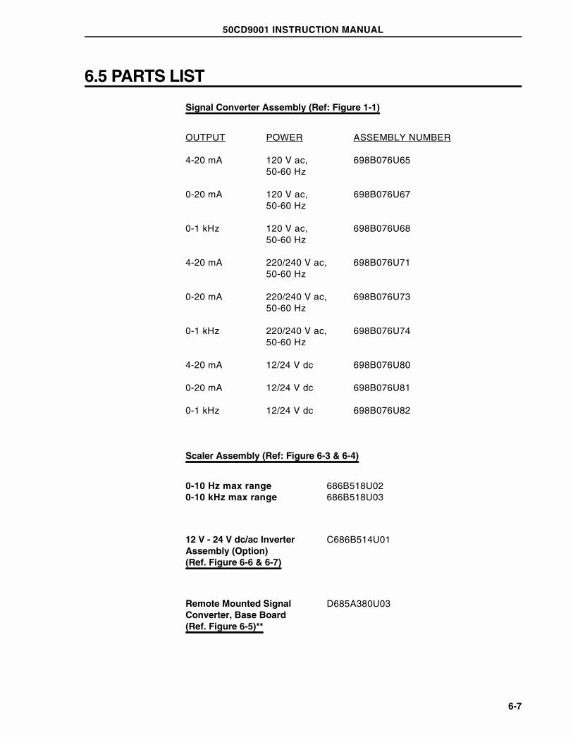
6.5 PARTS LIST
Signal Converter Assembly (Ref: Figure 1-1)
OUTPUT POWER ASSEMBLY NUMBER
4-20 mA 120 V ac, 50-60 Hz
698B076U65
0-20 mA 120 V ac,50-60 Hz
698B076U67
0-1 kHz 120 V ac, 50-60 Hz
698B076U68
4-20 mA 220/240 V ac,50-60 Hz
698B076U71
0-20 mA 220/240 V ac,50-60 Hz
698B076U73
0-1 kHz 220/240 V ac,50-60 Hz
698B076U74
4-20 mA 12/24 V dc 698B076U80
0-20 mA 12/24 V dc 698B076U81
0-1 kHz 12/24 V dc 698B076U82
Scaler Assembly (Ref: Figure 6-3 & 6-4)
0-10 Hz max range 686B518U020-10 kHz max range 686B518U03
12 V - 24 V dc/ac InverterAssembly (Option)(Ref. Figure 6-6 & 6-7)
C686B514U01
Remote Mounted SignalConverter, Base Board (Ref. Figure 6-5)**
D685A380U03
50CD9001 INSTRUCTION MANUAL
6-7

Adaptor Board (w/P1 & P2)**(Ref. Figure 1-1)
686B630U01
Rate Indicator Assembly,Integral Mounted Option(Ref. Figure 1-2)
614B876U01
Fuse, 1/4A for ConverterAssembly
151B014U01
Cable Assembly‡, Converterto base or primary board(Ref. Figure 6-5)
686B631U01
**Used only when remote mounted Signal Converter specified.
‡Supplied as part of Signal Converter Assembly
50CD9001 INSTRUCTION MANUAL
6-8

FIGURE 6-1. LAYOUT, SIGNAL CONVERTER BOARD
FIGURE 6-2. LAYOUT, OUTPUT BOARD
50CD9001 INSTRUCTION MANUAL
6-9

FIGURE 6-3. LAYOUT, SCALER ASSEMBLY (OPTION)
50CD9001 INSTRUCTION MANUAL
6-10

FIGURE 6-4. SCHEMATIC DIAGRAM, SCALER BOARD (OPTION)
50CD9001 INSTRUCTION MANUAL
6-11

FIGURE 6-5. EXPLODED VIEW, REMOTE MOUNTED SIGNAL CONVERTER
50CD9001 INSTRUCTION MANUAL
6-12

FIGURE 6-6. LAYOUT, DC/AC INVERTER (OPTIONAL)
FIGURE 6-7. SCHEMATIC DIAGRAM, DC/AC INVERTER
50CD9001 INSTRUCTION MANUAL
6-13

FIGURE 6-8. SCHEMATIC DIAGRAM, BASE BOARD FOR REMOTEMOUNTED SIGNAL CONVERTER
50CD9001 INSTRUCTION MANUAL
6-14

DOCUMENTATION QUESTIONNAIRE
Your answers to the questions below and other comments assist us in publishing better documentation. If an answer requires explanation please use the space provided. All commentsand suggestions become the property of ABB Automation Inc.
1. Title of Document? _________________________________________________________
2. Does this document meet your needs?__________________________________________
3. Is the information:
Easily understandable?______________________________________________________
_________________________________________________________________________
_________________________________________________________________________
Properly organized? ________________________________________________________
_________________________________________________________________________
Complete? ________________________________________________________________
_________________________________________________________________________
_________________________________________________________________________
Sufficiently illustrated? ______________________________________________________
_________________________________________________________________________
_________________________________________________________________________
OTHER COMMENTS
(Please include page and/or figure number.)
_________________________________________________________________________
_________________________________________________________________________
_________________________________________________________________________
_________________________________________________________________________
_________________________________________________________________________
Name _____________________________
Address _____________________________
_____________________________
_____________________________
If ABB employee, please includedepartment number.
No postage necessaryif mailed in the U.S.A.
FORM NO. 265-304
CU
T A
LO
NG
LIN
E,
FO
LD
, S
TA
PL
E
IB 50CD9001 ANALOG CONVERTER PN 24399A

_ _ _ _ _ _ _ _ _ _ _ _ _ _ _ _ _ _ _ _ _ _ _ _ _ _ _ _ _ _ _ _ FOLD 1 _ _ _ _ _ _ _ _ _ _ _ _ _ _ _ _ _ _ _ _ _ _ _ _ _ _ _ _ _ _ _ _ _ _
POSTAGE WILL BE PAID BY ADDRESSEE:
_ _ _ _ _ _ _ _ _ _ _ _ _ _ _ _ _ _ _ _ _ _ _ _ _ _ _ _ _ _ _ _ _ _ _ FOLD 2 _ _ _ _ _ _ _ _ _ _ _ _ _ _ _ _ _ _ _ _ _ _ _ _ _ _ _ _ _ _NO POSTAGE
NECESSARY
IF MAILED
IN THE
UNITED STATES
BUSINESS REPLY MAILFIRST CLASS PERMIT NO. 86 WARMINSTER, PA
ABB INSTRUMENTATIONFISCHER & PORTERDEPARTMENT 261 / A2125 EAST COUNTY LINE ROADWARMINSTER, PA 18974
Attention: Technical Publications
STAPLEHERE

Copyright 1999 by ABB Automation Inc., as an Unpublished Work Registered Trademark of ABB Automation Inc.
Trademark of ABB Automation Inc.
ABB Automation Inc.Instrumentation Division125 East County Line RoadWarminster, PA 18974 USATel. 215-674-6000FAX: 215-674-7183
ABB Instrumentation LtdHoward Road, St. NeotsCambs. England, PE19 3EUTel. 44 (0) 1480-475321FAX: 44 (0) 1480-217948
ABB Kent-Taylor spaVia Statale 11322016 Lenno (Como) ItaliaTel. 39 (0) 344 58111FAX: 39 (0) 344 56278