instruction manual - clearcom.com · rcs-2000 source assignment panel 1-1 operation description...
TRANSCRIPT

SOURCE ASSIGNMENT PANEL
I N S T R U C T I O N M A N U A L
RCS-2000

RCS-2000 Source Assignment Panel Instruction Manual 2001 Clear-Com Intercom SystemsAll Rights Reserved
Part Number 810272 Rev. A
Clear-Com Intercom Systems4065 Hollis StreetEmeryville, CA 94608-3505U.S.A
Clear-Com is a registered trademark of Clear-Com Intercom Systems.The Clear-Com Logo is a registered trademark of Clear-Com Intercom Systems.Matrix Plus is a registered trademark of Clear-Com Intercom Systems. Windows and Windows NT are registered trademarks of Microsoft Corp.

R C S - 2 0 0 0 S O U R C E A S S I G N M E N T P A N E L i
CONTENTSOPERATION 1-1Description . . . . . . . . . . . . . . . . . . . . . . . . . . . . . . . . . . . . . . . . . . . . . . . . . . 1-1
Overview . . . . . . . . . . . . . . . . . . . . . . . . . . . . . . . . . . . . . . . . . . . . . . . . 1-1Remote-Controlled Operation. . . . . . . . . . . . . . . . . . . . . . . . . . . . . . . . 1-1Typical Applications . . . . . . . . . . . . . . . . . . . . . . . . . . . . . . . . . . . . . . . 1-2
Connecting Multiple RCS-2000 Units . . . . . . . . . . . . . . . . . . . . . . . . . . . . . 1-2
ISO Channels and Groups. . . . . . . . . . . . . . . . . . . . . . . . . . . . . . . . . . . . . . . 1-3
Powering the System . . . . . . . . . . . . . . . . . . . . . . . . . . . . . . . . . . . . . . . . . . . 1-5Powering a Single RCS-2000 Unit . . . . . . . . . . . . . . . . . . . . . . . . . . . . . 1-5Powering Multiple RCS-2000 Units . . . . . . . . . . . . . . . . . . . . . . . . . . . 1-5
Front Panel . . . . . . . . . . . . . . . . . . . . . . . . . . . . . . . . . . . . . . . . . . . . . . . . . . 1-6Lights . . . . . . . . . . . . . . . . . . . . . . . . . . . . . . . . . . . . . . . . . . . . . . . . . . 1-6Preset Button . . . . . . . . . . . . . . . . . . . . . . . . . . . . . . . . . . . . . . . . . . . . . 1-7Code and Lock/Unlock Buttons . . . . . . . . . . . . . . . . . . . . . . . . . . . . . . 1-8Remote RCU-60 Front-Panel Jack . . . . . . . . . . . . . . . . . . . . . . . . . . . 1-10
Rear Panel . . . . . . . . . . . . . . . . . . . . . . . . . . . . . . . . . . . . . . . . . . . . . . . . . . 1-10Address Switch. . . . . . . . . . . . . . . . . . . . . . . . . . . . . . . . . . . . . . . . . . . 1-10Code-Reset Button . . . . . . . . . . . . . . . . . . . . . . . . . . . . . . . . . . . . . . . 1-11Remote RCU-60 Rear-Panel Jack . . . . . . . . . . . . . . . . . . . . . . . . . . . . 1-11PC Serial Port . . . . . . . . . . . . . . . . . . . . . . . . . . . . . . . . . . . . . . . . . . . 1-11Preset-Select Contact Closure . . . . . . . . . . . . . . . . . . . . . . . . . . . . . . . 1-12Termination Switches . . . . . . . . . . . . . . . . . . . . . . . . . . . . . . . . . . . . . 1-12
INSTALLATION 2-1Unpacking the RCS-2000 . . . . . . . . . . . . . . . . . . . . . . . . . . . . . . . . . . . . . . . 2-1
Wiring Overview. . . . . . . . . . . . . . . . . . . . . . . . . . . . . . . . . . . . . . . . . . . . . . 2-1Source Connections . . . . . . . . . . . . . . . . . . . . . . . . . . . . . . . . . . . . . . . . 2-2Power Patch Panel Connections . . . . . . . . . . . . . . . . . . . . . . . . . . . . . . 2-2Destination Connections . . . . . . . . . . . . . . . . . . . . . . . . . . . . . . . . . . . 2-2Source Expansion Connections . . . . . . . . . . . . . . . . . . . . . . . . . . . . . . . 2-2
Powering the RCS-2000 and Destinations . . . . . . . . . . . . . . . . . . . . . . . . . . . 2-2Powering from Party-Line Sources . . . . . . . . . . . . . . . . . . . . . . . . . . . . . 2-2Powering from TW Party-Line Sources . . . . . . . . . . . . . . . . . . . . . . . . . 2-5Powering the RCS-2000 from a Separate Power Supply . . . . . . . . . . . . . 2-6
Connecting and Setting Rear Panel Controls . . . . . . . . . . . . . . . . . . . . . . . . . 2-7Setting the Address Switch. . . . . . . . . . . . . . . . . . . . . . . . . . . . . . . . . . . 2-7Using the Code-Reset Button . . . . . . . . . . . . . . . . . . . . . . . . . . . . . . . . 2-8Connecting a Remote RCU-60 . . . . . . . . . . . . . . . . . . . . . . . . . . . . . . . 2-9Connecting a PC . . . . . . . . . . . . . . . . . . . . . . . . . . . . . . . . . . . . . . . . . . 2-9Wiring the Data-Links Connectors to Expansion Units . . . . . . . . . . . . 2-10Wiring the Preset-Select Contact Closure . . . . . . . . . . . . . . . . . . . . . . 2-11Setting Termination Switches. . . . . . . . . . . . . . . . . . . . . . . . . . . . . . . . 2-12

R C S - 2 0 0 0 S O U R C E A S S I G N M E N T P A N E Li i
Wiring Source Channels . . . . . . . . . . . . . . . . . . . . . . . . . . . . . . . . . . . . . . . 2-13Basic Switching Theory . . . . . . . . . . . . . . . . . . . . . . . . . . . . . . . . . . . . 2-13Wiring Source Channels in an 8-Source System. . . . . . . . . . . . . . . . . . 2-14Wiring Source Channels in a 15-Source System. . . . . . . . . . . . . . . . . . 2-15Wiring Source Channels in a 48- or 72-Destination System . . . . . . . . 2-15
Wiring Destinations . . . . . . . . . . . . . . . . . . . . . . . . . . . . . . . . . . . . . . . . . . 2-18
Wiring Summary for 8-Source Systems . . . . . . . . . . . . . . . . . . . . . . . . . . . . 2-19
Wiring Summary for 15-Source Systems . . . . . . . . . . . . . . . . . . . . . . . . . . . 2-20
MAINTENANCE 3-1Troubleshooting Tips. . . . . . . . . . . . . . . . . . . . . . . . . . . . . . . . . . . . . . . . . . . 3-1
Block Diagram . . . . . . . . . . . . . . . . . . . . . . . . . . . . . . . . . . . . . . . . . . . . . . . 3-2
Front Panel PCAComponent Layout Drawing. . . . . . . . . . . . . . . . . . . . . . . . . . . . . . . . . 3-3Bill of Materials . . . . . . . . . . . . . . . . . . . . . . . . . . . . . . . . . . . . . . . . . . . 3-4Schematic . . . . . . . . . . . . . . . . . . . . . . . . . . . . . . . . . . . . . . . . . . . . . . . 3-5
Main PCA . . . . . . . . . . . . . . . . . . . . . . . . . . . . . . . . . . . . . . . . . . . . . . . . . . . 3-7Component Layout Drawing. . . . . . . . . . . . . . . . . . . . . . . . . . . . . . . . . 3-7Bill of Materials . . . . . . . . . . . . . . . . . . . . . . . . . . . . . . . . . . . . . . . . . . . 3-8Schematic (1). . . . . . . . . . . . . . . . . . . . . . . . . . . . . . . . . . . . . . . . . . . . 3-10Schematic (2). . . . . . . . . . . . . . . . . . . . . . . . . . . . . . . . . . . . . . . . . . . . 3-11Schematic (3). . . . . . . . . . . . . . . . . . . . . . . . . . . . . . . . . . . . . . . . . . . . 3-12
Rear Panel PCA . . . . . . . . . . . . . . . . . . . . . . . . . . . . . . . . . . . . . . . . . . . . . . 3-13Component Layout Drawing. . . . . . . . . . . . . . . . . . . . . . . . . . . . . . . . 3-13Bill of Materials . . . . . . . . . . . . . . . . . . . . . . . . . . . . . . . . . . . . . . . . . . 3-14Schematic . . . . . . . . . . . . . . . . . . . . . . . . . . . . . . . . . . . . . . . . . . . . . . 3-15
GLOSSARY 4-1
SPECIFICATIONS 5-1RCS-2000 Unit . . . . . . . . . . . . . . . . . . . . . . . . . . . . . . . . . . . . . . . . . . . . . . . 5-1
RCS-2000 System . . . . . . . . . . . . . . . . . . . . . . . . . . . . . . . . . . . . . . . . . . . . . 5-2
CLEAR-COM LIMITED WARRANTY 6-1Factory Service. . . . . . . . . . . . . . . . . . . . . . . . . . . . . . . . . . . . . . . . . . . . . . . . 6-1
Warranty Repair . . . . . . . . . . . . . . . . . . . . . . . . . . . . . . . . . . . . . . . . . . . . . . 6-2
Non-Warranty Repair . . . . . . . . . . . . . . . . . . . . . . . . . . . . . . . . . . . . . . . . . . 6-2

R C S - 2 0 0 0 S O U R C E A S S I G N M E N T P A N E L 1 - 1
OPERATION
DESCRIPTION
OVERVIEWYou can quickly and easily assign remote stations or beltpacks to the channels of a main intercom station with an RCS-2000 Source Assignment Panel. One RCS-2000 unit can program up to 24 “destinations” to 8 “source” channels. Using a Windows-based PC, or the optional RCU-60 Remote Control Unit, you can program source/destination assignments from a distance of up to 300 feet (91 meters) from the RCS-2000 unit.
• “Sources” are typically the channels from a 4-, 8-, or 12-channel main or master station.
• “Destinations” are typically remote intercom stations, beltpacks, or other interfaces, but can also be groups of such devices connected together.
The RCS-2000 unit can store up to 14 “presets”—sets of pre-programmed source/destination assignments—which can be selected to go into operation within seconds as needed, using either the handheld RCU-60 Remote Control Unit, a PC, a contact closure, or directly from the front panel of the RCS-2000. The front panel can be “locked” to prevent unauthorized tampering.
With a Windows-based PC (95/98/ME/2000) and its companion software program, RCS-WIN, you can create presets and store them in your computer for current or future use. The RCS-WIN software offers a user-friendly onscreen image of an assignment panel with slider buttons that you move up or down to change assignments.
With the optional compact RCU-60 Remote Control Unit, you can select, create, and edit presets through its numerical LED readouts. The remote unit is compact, easy to store, and offers an alternative to using a PC.
The RCS-2000 requires very little electrical current to operate. Because of this, it operates from 30 VDC power, and no internal power supply is required. The unit can be powered by one of the channels of the main station or power supply that powers the system. In the event of a power loss, the latching relays in its switching matrix remain in position, maintaining the channel assignments.
REMOTE-CONTROLLED OPERATION The RCU-60 and the PC can be located up to 300 feet (91 meters) away from the RCS-2000 main unit, connected with Category-5 cable. This provides not only convenience and flexibility in system control, but can also save money during installation: the assignment panel no longer needs to be located in the control room area. This shortens cable runs (often improving intercom system performance) and allows more flexibility in location of the RCS-2000 main unit—both potential money savers.
• “Sources” are typically
the channels from a main
or master station.
• “Destinations” are
remote stations,
beltpacks, or other
devices that are assigned
to channels of the source
station.
• You can program
source/destination
assignments with the
RCU-60 Remote Control
Unit or with a
Windows-based PC.
1

R C S - 2 0 0 0 S O U R C E A S S I G N M E N T P A N E L1 - 2
If desired, the PC or wired remote can remain connected during system operation to offer real-time remote control of the system, although it is not necessary that they remain connected for the RCS-2000 to continue to function as programmed. If a PC is always connected to the system, an operator can access the system from anywhere in the world through the Internet and the use of special remote program software.
TYPICAL APPLICATIONSApplications will typically include any facility with at least four channels of party line and twelve or more “drops” where the assignment setups change on a regular basis: performing arts facilities, broadcast studios and remote trucks, convention centers, and houses of worship. Additional applications include simultaneous language translation and virtual-reality gaming and teaching/training facilities that use groups in simulators.
The RCS-2000 unit is compatible with Clear-Com and other popular party-line intercom systems.
CONNECTING MULTIPLE RCS-2000 UNITS Up to six RCS-2000 units can be wired together in various combinations for up to a 15-source by 72-destination system. There are six possible combinations of units.
A single RCS-2000 unit has 8 sources of audio and 24 remote destinations, as shown in Figure 1.
Figure 1: Sources and Destinations in a One-Unit Setup
Two RCS-2000 units can be connected together to provide either 15 sources of audio and 24 destinations or 8 sources of audio and 48 destinations as shown in Figure 2. The address switch on the rear panel of each unit must be set with the correct unit number to determine which configuration is chosen. Instructions for setting and changing unit numbers are provided in the Installation Chapter.
SOURCES 1-8
DESTINATIONS 1-24
• “Presets” are sets of
pre-programmed
source-to-destination
assignments that are
stored in the RCS-2000’s
memory. They can be
changed instantaneously
by a single mouse click or
push of a button.

R C S - 2 0 0 0 S O U R C E A S S I G N M E N T P A N E L 1 - 3
Figure 2: Possible Configurations with Two RCS-2000 Units
Other possible configurations include: 15 sources and 48 destinations (4 units), 8 sources and 72 destinations (3 units), and 15 sources and 72 destinations (6 units). Figure 3 illustrates all of the possible combinations of RCS-2000 units with the correct unit numbers for each configuration.
For information on installing and wiring expansion units, and for setting unit number addresses for each configuration, consult the Installation Chapter of this manual.
ISO CHANNELS AND GROUPS A single RCS-2000 unit has eight source channels available for use. If the main source intercom station uses less than the eight available channels, the remaining channels can still be used. For example, if a 4-channel MS-440 intercom station provides the first four source channels, there will be four additional lines available as source channels on the 8-channel RCS-2000.
These “virtual source channels” are called “ISO(lated)” channels, and the destinations assigned to them are called “ISO” groups because they are not connected to the main source intercom station. This in effect gives you four extra channels to use, in addition to the four channels on the MS-440 source station, offering a cost effective way to expand the functionality of your intercom system.
A typical application of an ISO channel is to allow two or three destinations to talk to each other independently of the other destinations on a source channel. To accomplish this, you assign the chosen destinations to an ISO channel as a separate preset, or as a source/destination edit within the current preset.
A system can also be set up to work without a main station if all eight channels are ISO channels. Destinations would be connected in the usual way and assignments would be made between the eight ISO channels. System power is still required.
SOURCES 1-8
DESTINATIONS 1-24 DESTINATIONS 25- 48
SOURCES 1-7
DESTINATIONS 1-24
SOURCES 8-15
MAIN UNIT
UNIT 1
MAIN UNIT UNIT 2

R C S - 2 0 0 0 S O U R C E A S S I G N M E N T P A N E L1 - 4
Figure 3: All Possible Configurations of RCS-2000 Units, with Unit Numbers for Each Configuration
DESTINATIONS 1-24DESTINATIONS 1-24
SOURCES 1-8SOURCES 1-7
SOURCES 8-15
MAIN UNIT
8 SOURCES X 24 DESTINATIONS
15 SOURCES X 24 DESTINATIONS
DESTINATIONS 25-48DESTINATIONS 1-24
SOURCES 1-8 MAIN UNIT
8 SOURCES X 48 DESTINATIONS
DESTINATIONS 1-24 DESTINATIONS 25-48
SOURCES 1-7
SOURCES 8-15
MAIN UNIT
15 SOURCES X 48 DESTINATIONS
DESTINATIONS 1-24 DESTINATIONS 25-48 DESTINATIONS 49-72
SOURCES 1-8 MAIN UNIT
8 SOURCES X 72 DESTINATIONS
DESTINATIONS 1-24 DESTINATIONS 25-48 DESTINATIONS 49-72
SOURCES 1-7
SOURCES 8-15
MAIN UNIT
15 SOURCES X 72 DESTINATIONS
UNIT 1
UNIT 2
UNIT 1
UNIT 2
UNIT 3
UNIT 2 UNIT 4
UNIT 1
UNIT 2
UNIT 3
UNIT 4
UNIT 5
�MAIN UNIT UNIT M
UNIT M
UNIT M
UNIT M
UNIT M
UNIT M

R C S - 2 0 0 0 S O U R C E A S S I G N M E N T P A N E L 1 - 5
POWERING THE SYSTEM
POWERING A SINGLE RCS-2000 UNITWhen a single RCS-2000 unit is powered, it goes through a start-up sequence that takes five seconds to complete. During this time the green Power light and red Fault light will be on. When the unit is ready for use, the green Power and Data lights will be on and the red Fault light will be off. The current preset number will appear on the front-panel display.
Figure 4: RCS-2000 Front Panel
POWERING MULTIPLE RCS-2000 UNITSIn a multi-unit configuration, the RCS-2000 main unit and all RCS-2000 expansion units must operate as one system, and therefore must all be powered from the same power supply.
When the RCS-2000 units are powered, each unit will go through a start-up sequence in which the system configuration is detected and validated. During this time, each unit’s green Power light and red Fault light will be on. For the main unit this sequence takes about five seconds, and for each expansion unit it takes about two seconds.
At the conclusion of the start-up sequence, each expansion unit will display its unit number as set by the address switch on the rear panel. Each expansion unit’s Fault light will be off and the green Power, Data, and System Expansion lights will be on.
When the main unit completes its start-up sequence successfully, it will display the current preset number. The main unit’s Fault light will be off and its green Send and Data lights will be on. If there are expansion units connected to the main unit, the main unit’s green System Expansion light will be on.
If the main unit detects an invalid system configuration during the start-up sequence, it will not complete the sequence. The main unit’s green Fault light will be on and its green System Expansion light will flash. Expansion units will display their addresses. To correct this condition, turn power to the system off, adjust the address switches on the back of the expansion units according to the numbers shown in Figure 3, and turn the power back on.
RCS-2000
PowerPreset/Code
RemoteRCU-60
PresetSelect
Code
Lock/Unlock
DataSys ExpFault Locked

R C S - 2 0 0 0 S O U R C E A S S I G N M E N T P A N E L1 - 6
FRONT PANEL
Figure 5: RCS-2000 Front Panel
LIGHTS
Power Light (1)When the green Power light is on, the unit is receiving DC power from the intercom line or lines of a “source” intercom station or from an external power supply.
Data Light (2)When the green Data light is slowly blinking, the unit is transmitting or receiving data from an attached RCU-60 Remote Control Unit or PC. When the unit is ready to transmit or receive data, the green Data light will be on solidly.
System Expansion (“Sys Exp”) Light (3)When the green System Expansion (“Sys Exp”) light is on solidly, the RCS-2000 main unit and all expansion units are properly connected in a multi-unit setup and are communicating data. A blinking light, or no light, indicates a problem such as an incorrect unit number in the multi-unit setup.
Fault Light (4)When the red Fault light remains on after the start-up sequence, there is a problem in a multi-unit setup such as a wiring problem or incorrect unit number.
Locked Light (5)When the Locked light is on, the Preset button on the front panel of the RCS-2000 is locked, and presets cannot be changed from the front panel. Presets can be changed using an RCU-60 Remote Control Unit or a PC, however, even if the Preset button is locked.
RCS-2000
PowerPreset/Code
RemoteRCU-60
PresetSelect
Code
Lock/Unlock
DataSys ExpFault
Locked
Power Light
Data Light
System-Expansion Light
Fault Light
Locked Light
Preset Button
Code Button
Lock/Unlock Button Remote RCU-60 Jack
1
2
3
4
5
6
7
8
9
• You can change the
current preset in one of
four ways: from the front
panel of the RCS-2000,
with an RCU-60 Remote
Control Unit, with a
Windows-based PC, or
with a contact closure.

R C S - 2 0 0 0 S O U R C E A S S I G N M E N T P A N E L 1 - 7
PRESET BUTTON (6)
Preset Configurations (“Presets”)
A “preset” is a group of source/destination assignments that you store for current or future use. The RCS-2000 unit’s memory can store 14 groups of source/destination assignments. Each group is called a “preset.” Source/destination assignments are always made within one of the 14 presets. The desired preset must be specified before making a source/destination assignment.
The number of source/destination assignments within a preset can be as few as one destination assigned to one source or as many as 72 destinations assigned to 15 sources (in a multi-unit system).
When you receive your system, all 14 available presets are set to a default configuration in which each destination is assigned to a source in numerical order, as shown in Figure 6. You can then change the source/destination assignments within each preset to suit your needs.
If at some point you want to set the system back to the default presets, you can do so by using the Code-Reset button on the rear panel of the RCS-2000. See “Using the Code-Reset Button” in the Installation Chapter for further instructions.
Figure 6: Default Source/Destination Assignments
You initially program presets using a handheld RCU-60 Remote Control Unit or a PC with RCS-WIN software. When you have programmed more than one preset, you can select between presets in one of four ways: with the preset button on the front panel of the RCS-2000; with a handheld RCU-60 Remote Control Unit; with a contact closure; or with a PC that has the RCS-WIN software installed.
1 2 3 4 5 6 7 8 9 10 11 12 13 14 15 16 17 18 19 20 21 22 23 24
1 x x x
2 x x x
3 x x x
4 x x x
5 x x x
6 x x x
7 x x x
8 x x x
SOURCES
DESTINATIONS

R C S - 2 0 0 0 S O U R C E A S S I G N M E N T P A N E L1 - 8
This chapter gives instructions for selecting a preset from the front panel of the RCS-2000. For instructions on selecting or editing a preset with the RCS-60 Remote Control Unit, see the RCU-60 Remote Control Unit Instruction Manual. For instructions on selecting, editing, or creating a preset with a Windows-based PC, see the RCS-WIN Software Instruction Manual. For instructions on selecting a preset with a contact closure, see “Wiring the Preset-Select Contact Closure” in the Installation Chapter of this manual.
Selecting Presets from the Front Panel of the RCS-2000
You can select which of the 14 presets will go into operation at any given time with the Preset button on the front panel of the RCS-2000.
To select a preset from the front panel of the RCS-2000 unit:
1. Repeatedly press the Preset button to progress through the available preset numbers until you reach the desired preset number. The display will progress from one preset to the next, starting at 1 and ending at 14. When it reaches preset 14, it will start again at preset 1.
2. When the desired preset number appears on the display, hold the Preset button down until the display goes blank, then release the button. Releasing the Preset button before the display goes blank will cancel the change. This feature prevents accidental changes.
The RCS-2000 main and expansion units will then change to the newly selected preset. When this change is complete, the main unit will display the new preset number in the “Preset/Code” window.
The change to the preset will take about two seconds for each main or expansion unit in the system. For example, changing a preset in a system with a main unit and two expansion units will take about six seconds.
Note: When you change a preset, the RCS-2000 will switch destination and source assignments within the unit, causing a clicking sound. This is normal.
CODE AND LOCK/UNLOCK BUTTONS (7 & 8) You can lock the Preset button on the RCS-2000’s front panel to prevent accidental or unauthorized changes to the selected preset from the front panel.
When you first receive your RCS-2000 unit, it is set to the factory default code of “0.” When the code is set to “0” the RCS-2000’s Preset button cannot be locked. If you do not want to use the lock feature, you can leave the RCS-2000 set to the factory default code of “0.”
If you want to lock the RCS-2000’s Preset button, you must first change the code from the “no-lock” code of “0” to another single-digit code called an “unlock” code, and then lock the unit. See the following section “Changing the Unlock Code” for instructions.
Changing the Unlock Code
The process of changing the unlock code is the same whether you are changing from the factory default code of “0” to an unlock code, or changing from one unlock code to another.
• The RCU-60 Remote
Control Unit connects to
the RCS-2000 main unit
through up to 300 feet
(91 meters) of cable.
Category-5 cable is
recommended.

R C S - 2 0 0 0 S O U R C E A S S I G N M E N T P A N E L 1 - 9
Note: If the RCS-2000 unit’s Preset button is locked, you must unlock it first before changing the unlock code. See the following section entitled “Unlocking the RCS-2000” for instructions on unlocking the preset button. If the lock code is set to the factory default “no-lock” code of “0” you do not need to unlock it.
To change the unlock code:
1. Press and simultaneously hold the Lock and Code buttons on the main unit for three seconds until “L_” appears in the display. When “L_” appears in the display, release the buttons.
2. Repeatedly press the Code button until the desired new code appears in the display. • The unlock code is a single-digit character. Note that, in addition to the
numbers 1-9, there are some alphabetic and special characters available when choosing a code.
• If you release the Code button for three seconds before going on to the next step, the unlock-code change is cancelled.
3. When the desired new code appears in the display, press and release the Lock button. Within a few seconds, the current preset number will reappear in the display.
The unlock code is now changed. Write down the unlock code and keep it in a safe place for future reference. If you forget or misplace the code, there are only a limited number of ways to unlock the Preset button. For more information, see the section entitled “Code-Reset Button” later in this chapter
Locking the RCS-2000To lock the Preset button on the front panel of the RCS-2000:
• Press and hold the Lock button on the main unit for at least three seconds until the Locked light comes on.
• If the code is set to the factory default “no-lock” code of “0” you will not be able to lock the Preset button. When you press the Lock button, the Locked light will not turn on. You must first change the code from “0” to a single-digit unlock code, and then lock the unit. See the previous section entitled “Changing the Unlock Code” for instructions and more information.
The Preset button on the RCS-2000 is now locked. Note that the Lock button only locks the Preset button on the RCS-2000 unit. Presets can still be changed using the handheld RCU-60 Remote Control Unit or a PC even though the RCS-2000 Preset button is locked.
Unlocking the RCS-2000To unlock the Preset button, you must use the Code and Lock/Unlock buttons on RCS-2000 unit’s front panel to enter an unlock code.
To unlock the Preset button on the front panel of the RCS-2000:
1. Press and hold the Code button on the main unit for three seconds until “C_” appears on the display.
2. Repeatedly press the Code button until the correct unlock code appears.
• The preset button on the
RCS-2000 can be locked
to prevent unauthorized
or accidental changes.
• When an RCS-2000 is
purchased from
Clear-Com, it is set to the
“no-lock” code of 0 which
disables the preset-button
locking feature.

R C S - 2 0 0 0 S O U R C E A S S I G N M E N T P A N E L1 - 1 0
If the Code button is released for three seconds before going to the next step, the unlocking procedure is cancelled and the RCS-2000 remains locked.
3. When the correct code appears, press and release the Lock button. Within a second or two, the Locked light will turn off and the current preset number will appear on the display.
The Preset button on the RCS-2000 is now unlocked and you can select a new preset. To lock the Preset button again, and keep the same unlock code, simply press and hold the Lock button for three seconds.
REMOTE RCU-60 FRONT-PANEL JACK (9)An RCU-60 Remote Control Unit can be plugged into the front-panel jack to provide additional programming capability. The RCU-60 connects to the RCS-2000 unit through Category-5 cable with RJ-45 connectors. The RCS-2000 unit will recognize the presence of the RCU-60 and will begin communicating with it after it has been plugged in for a few seconds.
While an RCU-60 is plugged into the front-panel jack, communication with a PC or with a rear-panel connected RCU-60 will be suspended.
REAR PANEL
Figure 7: RCS-2000 Rear Panel
ADDRESS SWITCH (1)An RCS-2000 unit’s address switch is set when it is installed and should not be changed unless the system is being reinstalled or reconfigured.
The position of this switch can be determined from the RCS-2000 unit’s front-panel display. If the address switch is set to “M,” then the unit functions as a main unit and displays the preset number. If the address switch is set to 1, 2, and so forth, then the unit functions as an expansion unit and displays the expansion unit numbers “U1,” “U2,” and so forth on its front-panel display.
13
1 2 3 4 5 6 7 8 9 10 11 12 13 14 15 16 17 18 19 20 21 22 23 24DESTINATION POWER
1 2 3 4 5 6 7 8SOURCE POWER SCE RCS PWR
13DESTINATIONS
14 15 16 17 18 19 20 21 22 23 24
1DESTINATIONS
2 3 4 5 6 7 8 9 10 11 12
1SOURCES
2 3 4 5 6 7 8
SOURCE EXPANSIONS14 15 16 17 18 19 20 21 22 23 24
1SOURCE EXPANSIONS
2 3 4 5 6 7 8 9 10 11 12
MTXCONT
DATALINKS
PC SERIALPORT
RCU-60
M
42A1
35
BADDRESS
1 2 3 84 5 6 7
TERMINATIONSWITCHES
ON
OFF
CODE RESET
Address Switch Remote RCU-60 Jack
PC Serial Port
Data Links
Preset-Select Contact
Code-Reset Button
Termination Switches
1
2
3
4
5
6
7
• If the lock light is on, you
cannot change the preset
from the front panel. For
security reasons you
cannot change the unlock
code either. You must
unlock the unit first.

R C S - 2 0 0 0 S O U R C E A S S I G N M E N T P A N E L 1 - 1 1
In a multi-unit setup, the main unit is the only unit that will display the currently selected preset. All of the expansion units will display only their unit number in the multi-unit setup.
For more information on selecting or changing an address with the address switch, see the section entitled “Setting the Address Switch” in the Installation Chapter.
CODE-RESET BUTTON (2)If you forget or misplace your unlock code, there are only three ways to unlock the RCS-2000 unit’s Preset button without it:
• Try all 32 unlock codes.
• Use the Code-Reset button to restore all source/destination assignments to their factory default positions. This will also reset the unlock code back to the “unlock” code of 0. For instructions, see the section entitled “Using the Code-Reset Button” in the Installation Chapter.
• Use the Code-Reset button in conjunction with a PC and RCS-WIN software to set the unlock code back to the “unlock” code of 0 without changing the source/destination assignments back to their factory default settings. For instructions see the RCS-WIN Instruction Manual.
REMOTE RCU-60 REAR-PANEL JACK (3) An additional RCU-60 Remote Control Unit can be connected to the rear panel of the RCS-2000 unit. It connects to the RCS-2000 with Category-5 cable terminated with RJ-45 connectors.
Only one RCU-60 Remote Control Unit can operate at any one time. Communication with an RCU-60 connected to the rear-panel will be suspended if an RCU-60 is plugged into the front-panel jack. The front-panel RCU-60 always takes precedence over the rear-panel RCU-60.
Warning: Do not connect a PC to the PC serial port while an RCU-60 is plugged into the rear-panel RCU-60 jack. Doing this will connect multiple serial ports on the rear panel which are not designed to be connected. Either one or both of the ports will not work.
PC SERIAL PORT (4)For ultimate programming capability, you can connect a PC (Windows 95/98/ME/2000) to the PC serial port on the back of the RCS-2000 main unit. You can then program the RCS-2000 directly from the PC. The PC must have the RCS-WIN program installed.
Do not connect an RCU-60 Remote Control Unit while the PC is in use. If you connect a front-panel RCU-60, communication to the PC will be suspended. If you connect a rear-panel RCU-60, you will have connected multiple serial ports on the rear panel and either one or both of the ports will not work.
• With the Code-Reset
button you can set the
RCS-2000 preset button
back to a “no-lock”
status.
Warning: Do not connect a
PC to the PC serial port
while an RCU-60 is
plugged into the jack on
the rear panel.
• The “preset-select”
contact closure allows you
to use an external device
such as a wall- or
panel-mounted button to
change presets.

R C S - 2 0 0 0 S O U R C E A S S I G N M E N T P A N E L1 - 1 2
Refer to the Installation Chapter of this manual for further information regarding the PC serial port.
PRESET-SELECT CONTACT CLOSURE (5) You can wire the contact closure on the rear panel of the RCS-2000 so that you can select presets by pressing external buttons or other devices.
Refer to the Installation Chapter for more detailed information on the wiring and operation of this feature.
TERMINATION SWITCHES (6)The termination switches are set by a technician when the RCS-2000 is installed and should not be changed unless a specific need arises. If these switches are not set correctly, very poor intercom operation can result. Refer to the section entitled “Setting Termination Switches” in the Installation Chapter for guidelines on setting these switches.

R C S - 2 0 0 0 S O U R C E A S S I G N M E N T P A N E L 2 - 1
INSTALLATION
UNPACKING THE RCS-2000 When you unpack the RCS-2000 Source Assignment Panel, you will find the following items:
• RCS-2000 unit
• RCS-2000 manual
• 31 6-terminal Euro-block connectors
The Euro-block connectors press on to the rear-panel pins of the RCS-2000 unit. They are used to wire the unit to destinations and sources. You can install the connectors with the visible screws facing either upward or downward. However, facing the screws upward, so that they are visible from above, allows more flexibility in tightening the connections.
WIRING OVERVIEW Four sets of pins on the rear panel of the RCS-2000 connect the unit to source channels, destinations, expansion RCS-2000 units, and power.
An overview of the wiring is given below, with more detailed explanations and diagrams following later in the chapter.
Figure 8: Four Sets of Connection Pins on the Rear Panel of an RCS-2000 Unit
13
1 2 3 4 5 6 7 8 9 10 11 12 13 14 15 16 17 18 19 20 21 22 23 24DESTINATION POWER
1 2 3 4 5 6 7 8SOURCE POWER SCE RCS PWR
13DESTINATIONS
14 15 16 17 18 19 20 21 22 23 24
1DESTINATIONS
2 3 4 5 6 7 8 9 10 11 12
1SOURCES
2 3 4 5 6 7 8
SOURCE EXPANSIONS14 15 16 17 18 19 20 21 22 23 24
1SOURCE EXPANSIONS
2 3 4 5 6 7 8 9 10 11 12
MTXCONT
DATALINKS
PC SERIALPORT
RCU-60
M
42A1
35
BADDRESS
1 2 3 84 5 6 7
TERMINATIONSWITCHES
ON
OFF
CODE RESET
12
3
4
Power Patch Panel Source Connections (Power and Audio)
Destination Connections (Power and Audio) Source-8 Connection Points Tie Together or Connect to Expansion Units
• You connect the
RCS-2000 unit to source
channels, destinations,
expansion RCS-2000
units, and power.
2

R C S - 2 0 0 0 S O U R C E A S S I G N M E N T P A N E L2 - 2
SOURCE CONNECTIONS (1)You wire power and audio connections from the channels of a source intercom station to the row of pins labeled “Sources” (1–8) on the rightmost upper corner of the rear panel of the RCS-2000.
POWER PATCH PANEL CONNECTIONS (2)The power patch panel links power from sources to destinations. The leftmost upper two rows of pins on the rear panel of the RCS-2000 is the power patch panel. The pins are labeled “Destination Power” and “Source Power.”
DESTINATION CONNECTIONS (3)You wire power and audio to remote stations and beltpacks on the two rows of pins labeled “Destinations” (1–24) in the rightmost lower corner of the rear panel of the RCS-2000.
SOURCE EXPANSION CONNECTIONS (4) You wire source-8 connection points to each other or to expansion RCS-2000 units on the two rows of pins labeled “Source Expansions” in the rightmost lower corner of the rear panel of the RCS-2000.
You can wire these four sets of pins in any order. In multi-unit setups, however, layering the wiring by beginning with the lower-level pins and moving upward is more efficient.
POWERING THE RCS-2000 AND DESTINATIONS
POWERING FROM PARTY-LINE SOURCES The first step in an installation is to determine how you are going to supply power to the RCS-2000 unit and its connected remote stations and beltpacks. The RCS-2000 unit and its connected remote devices are typically powered by one or more channels of a main station or power supply. The RCS-2000 unit itself uses very little power.
Although the system can be powered by one channel of a source station, this is usually not recommended, especially for complex systems. Using multiple channels to power the system provides for power redundancy in the case of outages.
The source intercom station is typically a 2-, 4-, 8-, or 12-channel main or master station. To power the entire system from a source station, the source station must have an internal power supply.
Examples of stations that can power an entire system are Clear-Com’s MS-232 2-channel main station or its MS-440 4-channel main station. Two or more stations can be used as source stations for one system if additional channels are desired. For example, two MS-440 4-channel stations can be used to provide 8 source channels.
• In a multi-unit setup, the
RCS-2000 main unit and
all RCS-2000 expansion
units must be powered by
the same channel on the
same power supply.

R C S - 2 0 0 0 S O U R C E A S S I G N M E N T P A N E L 2 - 3
A station without an internal power supply can still serve as a source station if an external power supply is added. For example, Clear-Com’s MS-812A 12-channel master station can serve as a source station if you add PS-232 (2-channel) or PS-464 (4-channel) power supplies.
If expansion RCS-2000 units are added, the main unit and all expansion units must be powered by the same channel on the same power supply so that the main unit can correctly determine the size and configuration of the entire system.
Destinations can be powered from the power patch panel on the RCS-2000 or from external power supplies. Power from pin 2 of each source channel is connected internally to the respective “Source Power” connection in the power power patch area. Destination power connections for each destination are connected internally to pin 2 of the respective destination connections.
The connection scheme is very flexible, so there are a number of ways that power can be patched. Strategies for providing power to the RCS-2000 main unit, expansion units, and destinations are discussed in the following sections.
Powering from Multiple Party-Line Source Channels
Figure 9 shows how multiple source channels can power the RCS-2000 unit and all connected remote destinations.
Each source channel powers three destinations. Power from the first source channel powers the RCS-2000 unit and destinations 1, 2, and 3; power from the second source channel powers destinations 4, 5, and 6; and so on through the eighth source channel which powers destinations 22, 23 and 24.
The advantage of this connection strategy is that if the power for one destination is shorted, it will only affect two others, assuming that the eight source power channels are individually short protected.
When power is monitored with the RCU-60 Remote Control Unit or with the PC, it will be possible to more closely detect which destination's power is shorted because the short can be isolated to one of eight groups of destinations.
Figure 9: Powering the RCS-2000 from Multiple Source Channels
Powering from One Party-Line Source Channel
Figure 10 shows how power from one channel of the source intercom station can power the RCS-2000 unit and all connected remote destinations.
• The data cables between
expansion units should
not exceed 6 feet (2
meters) each.

R C S - 2 0 0 0 S O U R C E A S S I G N M E N T P A N E L2 - 4
Power from the source intercom station’s one channel is patched to the power connection for the RCS-2000 and to the power connections for all remote destination stations.
The main advantage of this wiring is its simplicity. The disadvantage is that a short on one destination’s cable can bring the whole system down. When power monitoring is done with the RCU-60 or the RCS-WIN PC program, it will not be possible to detect which destination's power is shorted.
Figure 10: Powering the RCS-2000 from a Single Source Channel
Powering from a Separate Power Supply
The third way of connecting power involves the use of a separate high-current 30 VDC power supply. The power supply is connected directly to the RCS-2000’s power input connector, and fuses or circuit breakers are wired as shown in Figure 11 to protect each destination’s power circuit individually.
In this configuration, either an RCU-60 Remote Control Unit or a PC with the RCS-WIN program installed will be able to detect precisely which destination’s power circuit is shorted.
Figure 11: Powering the RCS-2000 from an Individual Destination
+30 VDC�
Power Supply�Ground�
24�23�22�21�20�19�18�17�16�15�14�13�12�11�10�9�8�7�6�5�4�3�2�1�Destination Power Channel Fuses or Circuit Breakers�

R C S - 2 0 0 0 S O U R C E A S S I G N M E N T P A N E L 2 - 5
POWERING FROM TW PARTY-LINE SOURCES You can operate the RCS-2000 using TW party-line sources provided that each source channel is powered. If power does not exist on every intercom channel, you can add it using TWC-10A or TWC-104 TW Adapters. The wiring is as shown in Figure 12. Because 2-amp relays are used, they can easily handle the DC current on the line as they switch.
Figure 12: TW Source Wiring for a 4-Source System
When powering the stations this way, you should not connect the destination power block to the source power block. Instead, connect a jumper wire on each destination output using the connection options shown in Figure 12.
You can take RCS-2000 power from one of the source channels using the power patch panel. The current drain of the RCS-2000 is designed not to interfere with the audio on the powered source. You connect a jumper from the desired source in the source power block to the RCS power connection. You must also add a jumper between the pin-2 and pin-3 (or the pin-5 and pin-6) connections for the selected source in the sources block. In Figure 13, power from Source 8 is being used to power the RCS-2000.
Source 4�Source 3�
Source 2�Source 1�
Main Unit�
MS-440�4-Channel�
Main Station�
TWC-10A� TWC-10A� TWC-10A� TWC-10A� D C B A�
A� A� A� A�TW� TW� TW� TW�
1 2�
Shield�
3 (NC)�
Turn MS-440�Channel�
Terminations ON�
Turn RCS-2000�Channel Terminations�
1-4 OFF�
1 2 3�
Shield�TW Destination�
Channels�1 & 2� 3 & 4� 5 & 6� 7 & 8� 9 & 10� 11 & 12�

R C S - 2 0 0 0 S O U R C E A S S I G N M E N T P A N E L2 - 6
Figure 13: Powering the RCS-2000 from Source 8
Table 1 gives the pin assignments for wiring RTS source channels.
Table 1: Pinouts for Wiring RTS Source Channels
POWERING THE RCS-2000 FROM A SEPARATE POWER SUPPLYIt is not essential that you power the RCS-2000 unit from the same supply as the rest of the intercom system. Similarly, if you use the RCS-2000 to switch signals in a non-intercom application, there may be no intercom power supply and the destinations will not need +30 VDC power. The following figure shows the connections needed to power the RCS-2000 from a separate 30 VDC supply.
Figure 14: Powering the RCS-2000 from a Separate Power Supply
PIN# FUNCTION
Pin#1 Ground
Pin#2 No connection
Pin#3 Channel B
Pin#4 No connection
Pin#5 No connection
Pin#5 Channel A
+30 VDC�
Power Supply Ground�

R C S - 2 0 0 0 S O U R C E A S S I G N M E N T P A N E L 2 - 7
CONNECTING AND SETTING REAR PANEL CONTROLS
Figure 15: RCS-2000 Rear Panel
SETTING THE ADDRESS SWITCH (1)
Setting the Address Switch for a Single-Unit System
If you are using one RCS-2000 unit, the address switch should be set to “M” for main unit. This is the factory default setting that the unit is shipped with, so no changes are necessary to the address switch if you are using one RCS-2000 unit.
Setting Address Switches in a Multi-Unit System
In a multi-unit system, each RCS-2000 unit must be defined as a main unit or an expansion unit in the switching array. Since all RCS-2000 units are identical electronically, setting their address switches is the only way to define their unique functions in a multi-unit setup.
When the system is installed, you turn the address switch to the unit numbers shown in Figure 16.
Figure 16: Unit Numbers
13
1 2 3 4 5 6 7 8 9 10 11 12 13 14 15 16 17 18 19 20 21 22 23 24DESTINATION POWER
1 2 3 4 5 6 7 8SOURCE POWER SCE RCS PWR
13DESTINATIONS
14 15 16 17 18 19 20 21 22 23 24
1DESTINATIONS
2 3 4 5 6 7 8 9 10 11 12
1SOURCES
2 3 4 5 6 7 8
SOURCE EXPANSIONS14 15 16 17 18 19 20 21 22 23 24
1SOURCE EXPANSIONS
2 3 4 5 6 7 8 9 10 11 12
MTXCONT
DATALINKS
PC SERIALPORT
RCU-60
M
42A1
35
BADDRESS
1 2 3 84 5 6 7
TERMINATIONSWITCHES
ON
OFF
CODE RESET
Address Switch Remote RCU-60 Jack
PC Serial Port
Data Links
Preset-Select Contact
Code-Reset Button
Termination Switches
1
23
4
5
6 7
Main Unit Sources 1–8 (1–7*)Destinations 1–24
Unit 2 Sources 1–8 (1–7*)Destinations 25–48
Unit 4 Sources 1–8 (1–7*)Destinations 49–72
Unit 1Sources 8–15
Destinations 1–24
Unit 3Sources 8–15
Destinations 25–48
Unit 5Sources 8–15
Destinations 49–72
* If Unit 1 exists, then the Main Unit and Units 2 and 4 connect to Sources 1–7 instead of 1–8.

R C S - 2 0 0 0 S O U R C E A S S I G N M E N T P A N E L2 - 8
Note: Before setting an address switch to the desired unit number, you must turn the power to the system off. When the system is powered back up, the changes to unit numbers take effect.
To set the address switch to the desired unit number:
1. Turn the power to the RCS-2000 unit off. 2. Use a small flat-bladed screwdriver to turn the rotary address switch to the
correct unit number. 3. Set the switch to “M” for the main unit, “1” for expansion unit 1, “2” for
expansion unit 2, and so on. • The “A” and “B” positions should not be used. They are reserved for factory
testing.
• Note that the small arrow on the shaft of the switch indicates the selected position. For example, in the figure shown below, the switch is set to “M.” It is not set to “2” or “A.”
Figure 17: Address Switch
4. Turn the power to the unit back on. The front-panel “Preset/Code” window will indicate whether the unit is a main or expansion unit. A main unit will show the current preset number in the display. An expansion unit, however, will always show only its unit number on the front-panel display.
USING THE CODE-RESET BUTTON (2)The Code-Reset button has two functions. You can use it to set the RCS-2000 back to a “no-lock” status if you have forgotten your unlock code. To do this you need a PC with the RCS-WIN program installed. For detailed instructions, see the RCS-WIN Instruction Manual.
The second function of the Code-Reset button is to return a main or expansion unit to its factory default settings. If there are presets defined and set, or source and destination names entered, they will all be erased when this function is used. This function must therefore only be performed with careful consideration. This function only affects the main or expansion unit it is performed upon; it does not affect an entire system. Setting a unit back to its factory default settings will also set the unlock code for that unit back to the “no-lock” code of 0.
WARNING: The following steps will completely erase all programmed settings and return the main or expansion unit to the factory default settings.
M
4
2A
1
35
B

R C S - 2 0 0 0 S O U R C E A S S I G N M E N T P A N E L 2 - 9
To return an RCS-2000 unit to the factory default settings:
1. Turn power to the unit off.2. Press and hold the Code-Reset button.3. Turn power to the unit on while continuing to hold the Code-Reset button.4. Release the Code-Reset button when the front-panel display reads “CC.”5. If the Locked light remains on, turn power to the unit off and then on again.
After a few seconds, the start-up sequence will begin and the factory default settings will be restored.
CONNECTING A REMOTE RCU-60 (3)For additional programming capability, you can connect an RCU-60 Remote Control Unit to the rear-panel jack provided for it. The RCS-2000 will recognize the RCU-60 and begin communicating with it a few seconds after it is connected.
Only one RCU-60 Remote Control Unit can operate at any one time. If at any one time two RCU-60s are connected, only the front-panel RCU-60 will operate. The RCU-60 connected to the front-panel jack always takes precedence over the RCU-60 connected to the rear-panel jack.
WARNING: Do not connect a PC to the PC serial port while an RCU-60 Remote Control Unit is plugged into the jack on the rear panel. Doing this will connect multiple serial ports which are not designed to be connected. Either one or both of the ports will not work.
CONNECTING A PC (4)For ultimate programming capability, you can connect a PC to the PC serial port on the back of the main RCS-2000 unit. You can then program the RCS-2000 directly from the PC. The PC must have the RCS-WIN program installed.
Communication with the PC will be suspended if an RCU-60 Remote Control Unit is plugged into the front-panel jack.
WARNING: Do not connect an RCU-60 Remote Control Unit to the rear-panel jack while a PC is connected to the serial port. Doing this will connect multiple serial ports which are not designed to be connected. Either one or both of the ports will not work.
The communication interface is RS-232D and the settings are:
• 19200 baud
• 1 start bit
• 8 data bits
• 2 stop bits
• no parity
The RS-232D interface has a distance limitation of 300 feet of cable (91 meters), but this is subject to the quality of the wiring used and the presence of electrical
Warning: Do not connect a
PC and an RCU-60
Remote Control Unit to
the RCS-2000 unit at the
same time.

R C S - 2 0 0 0 S O U R C E A S S I G N M E N T P A N E L2 - 1 0
noise and interference along the cable run. The pinout of the DB-9F serial port connector on the rear panel is shown in the Table 2 below:
Table 2: Pinout of DB-9F Serial Port Connector
WIRING THE DATA-LINKS CONNECTORS TO EXPANSION UNITS (5)Two data-link pairs are provided on the rear panel of each RCS-2000 for connecting expansion units to the main unit. A single-pair connection between the main unit and each expansion unit is required so that the main unit can direct the operation of the system as a whole. This is a bi-directional, parallel connection, and the two data-link pairs are connected together internally, so there is no “in” or “out” connection per se. Note the location of the ground and data connection pins in the following diagram.
Figure 18: Ground and Data Connections for Linking RCS-2000 Units
You can “daisy-chain” the connections from unit to unit to connect all of the units together. Use wires of two different colors to connect the ground and data pins from unit to unit. You can use twisted pair or shielded wire. If you use shielded wire, connect the shield to the ground pin.
The length of each section of wire between units should be less than 6 feet (2 meters), although typically less than a foot of wire (30 centimeters) should be all that is necessary. The units should be linked as shown in the Figure 19. It does not matter in what order the main and numbered expansion units are connected, although connecting the units in numbered order should result in an installation that is more organized.
PIN SIGNAL FUNCTION
1 CF Received Line Signal Detector (not used)
2 RXD Serial data from the RCS-2000 to the PC
3 TXD Serial data from the PC to the RCS-2000
4 DTR Data Terminal Ready (connected to DSR)
5 GND Signal ground
6 DSR Data Set Ready (connected to DTR)
7 RTS Request to Send (connected to CTS)
8 CTS Clear to Send (connected to RTS)
9 RI Ring Indicator (not used)
DATALINKS
PRESETSELECT
CONTACT
Ground
Data
• The data links pairs
connect the main unit to
expansion units.

R C S - 2 0 0 0 S O U R C E A S S I G N M E N T P A N E L 2 - 1 1
Figure 19: RCS-2000 Units are “Daisy-Chained” Together
WIRING THE PRESET-SELECT CONTACT CLOSURE (6)The contact closure on the rear panel labeled “Preset-Select Contact” allows you to wire button or relay contacts to select presets. To use this feature, connect normally open button or relay contacts, or a +5 VDC (active low) logic output, to these contacts. For logic connections, note the ground and signal connections shown in Figure 20.
Figure 20: Ground and Signal Connections for a Logic-Output Device
To select a preset with a contact closure:
1. Close the contact the number of times that equals the desired preset number. Close the contact once for preset 1, twice for preset 2, and so on.
M
U1
U2
U3
U4
U5
Shield
Shield
DATALINKS
PRESETSELECT
CONTACT
Ground
Signal
• You can use button or
relay contacts to select
presets.

R C S - 2 0 0 0 S O U R C E A S S I G N M E N T P A N E L2 - 1 2
2. Hold each connection for at least three seconds. 3. Release the contacts.
The RCS-2000 will change to the selected preset.
If the sequence of contact closures stops with an open condition for two seconds, the change is cancelled. Each time a new sequence of contact closures is initiated, the counting begins from “1.” Selecting a preset with a contact closure in this way allows you to know which preset you have selected without visual indicators.
The timing of the contact closure is as follows:
• Counting contact closure: .25 to 1 second
• Release time between counting contact closures: .25 to 1 second
• Contact closure time required to enable preset change: 3 seconds or more
Note that all Clear-Com PL main stations and some remote stations have a contact closure triggered by the stage announce button. If the stage announce button is not being used for other purposes, it can serve as a preset-select connection for the RCS-2000.
You can select a preset with a preset-select contact even when a PC or RCU-60 is connected to the RCS-2000 unit at the same time. You can also select a preset when the RCS-2000 unit’s front-panel preset button is locked.
SETTING TERMINATION SWITCHES (7)Each Clear-Com party-line channel requires one and only one termination. The RCS-2000 provides switchable terminations at the source connections. Therefore, terminations for party-line channels coming from main stations or power supplies should be turned off at those sources to allow the RCS-2000 to provide the terminations. There will be less crosstalk and noise on the intercom lines if the terminations are located at the RCS-2000 rather than at the main stations or power supplies.
Terminations for each source channel should be switched on only at the RCS-2000 main unit and expansion unit 1. Termination switches on all other RCS-2000 expansion units should be switched off.
If there are unused source channels on any unit, the terminations to those source channels should be turned on.
When the RCS-2000 is used for general switching of devices other than Clear-Com party lines, the termination switches on all of the units should be turned off.
Table 3: Termination Switch Settings
DEVICE TERMINATION SWITCH
Main source station off
Power supply off
RCS-2000 main unit on
RCS-2000 expansion unit 1 on
All other RCS-2000 expansion units off
Any unused source channel on any unit on

R C S - 2 0 0 0 S O U R C E A S S I G N M E N T P A N E L 2 - 1 3
WIRING SOURCE CHANNELS
BASIC SWITCHING THEORY Figure 21 is a schematic diagram of an RCS-2000 switching block. Under microprocessor control, the switching block can move a destination between sources 1 through 8.
Figure 21: Basic RCS-2000 Switching Block
Connection points for sources 1 through 7 are internally wired together. Connection points for source 8 are not internally wired together, but are wired outward instead, to pins on the rear panel of the RCS-2000 unit. This is done so that source 8 can serve as a bridge to an expansion RCS-2000 unit, if necessary.
Figure 22: Multiple Switching Blocks in One RCS-2000 Unit
In a single-unit system, the source-8 pins on the rear panel of the RCS-2000 must be manually wired together in order for source 8 to work properly. In a multi-unit system, the source-8 pins on the first, or main, unit must be wired to source-connection pins on the next RCS-2000 unit in the system, and so on, to allow for expansion of the number of sources.
When an RCS-2000 main unit is connected to one expansion RCS-2000 unit, the resulting system will be able to switch 24 destinations to 15 sources. The switching blocks in the two units combine as shown in Figure 23. Note that the source-8 connection points on the main unit (the upper unit in the diagram) are not connected together, but are connected instead to the source connection points on the expansion unit (the lower unit in the diagram). Note also that the source-15 connection points on the expansion unit are not connected in the
Source 8
�
Source 1
Source 2Source 3
Source 4
Source 5
Source 6Source 7
To Destination 1
Source 8
�
Source 1
Source 2
Source 3Source 4
Source 5
Source 6Source 7
To Destination 1
Source 8
�
Source 1
Source 2
Source 3
Source 4
Source 5
Source 6Source 7
To Destination 2
Source 8
�
Source 1
Source 2Source 3
Source 4
Source 5
Source 6
Source 7
To Destination 3
Source 8
�
Source 1
Source 2Source 3
Source 4
Source 5
Source 6Source 7
To Destination 24
In a single-unit system, source 8 �connection points must be manually�connected on the rear panel of the �RCS-2000 unit
• Source-8 pins must be
wired together in a
single-unit system, or
wired to another
RCS-2000 unit in a
mulit-unit system.

R C S - 2 0 0 0 S O U R C E A S S I G N M E N T P A N E L2 - 1 4
diagram, to indicate that they must be manually wired together on the rear panel of the expansion unit. (See Figures 24 and 25 for examples of rear-panel wiring.)
Figure 23: Switching Block Configuration in a Two-Unit System
All source/destination connections are maintained even when the RCS-2000 is not powered. The switched connections are isolated from any other internal wiring and are rated at two amperes. Consequently, the RCS-2000 can be used for switching applications not limited to intercom. In addition to party-line intercom, other applications include 70-volt speaker switching and industrial applications limited only by the designer’s imagination.
WIRING SOURCE CHANNELS IN AN 8-SOURCE SYSTEM
Wiring Source Channels
In 8-source systems, the source channels are wired as shown in Figure 24. The pinout to the XLR cables connecting to main stations or power supply channels is simply 1-2-3 from left to right. Pin 3 is the switched connection.
Wiring Source-8 Connection Points
The source-8 connection points, which have been wired out to pins on the rear panel labeled “source expansions” (as explained in the previous section, “Basic Switching Theory”) must now be wired together as shown in Figure 24. The leftmost wire coming from the source expansion connector in the diagram connects the joined sources to source 8 and its termination. The same source wiring applies to expansion units 2 and 4, if they are used.
�
Source 1
Source 2
Source 3Source 4
Source 5
Source 6Source 7
To Destination 1 �
Source 1
Source 2
Source 3
Source 4
Source 5
Source 6Source 7
To Destination 2 �
Source 1
Source 2Source 3
Source 4
Source 5
Source 6
Source 7
To Destination 3 �
Source 1
Source 2Source 3
Source 4
Source 5
Source 6
Source 7
To Destination 24
Source 15
�
Source 8
Source 9
Source 10Source 11
Source 12
Source 13Source 14
Source 15
�
Source 8
Source 9
Source 10
Source 11
Source 12
Source 13Source 14
Source 15
�
Source 8
Source 9Source 10
Source 11
Source 12
Source 13
Source 14
Source 15
�
Source 8
Source 9Source 10
Source 11
Source 12
Source 13
Source 14
Source-15 connection points must be�manually wired together on the rear panel �of the expansion unit
Source-8 connection points �have moved from main unit to �expansion unit
�
• The RCS-2000 can be
used for switching
applications not limited to
intercom.

R C S - 2 0 0 0 S O U R C E A S S I G N M E N T P A N E L 2 - 1 5
Figure 24: Source Wiring for an 8-Source System
WIRING SOURCE CHANNELS IN A 15-SOURCE SYSTEM
Wiring Source-8 Connection Points to Expansion Unit 1
Figure 25 shows how 15-source systems must be wired. The source-expansion pins of the main unit must be wired to expansion unit 1. Source 8 connects to unit 1 and the source-8 connections on the main unit are left disconnected. This wiring also applies to expansion units 2 and 3, as well as expansion units 4 and 5, if used. Also shown in Figure 25 is the data-link connection between the main unit and unit 1.
WIRING SOURCE CHANNELS IN A 48- OR 72-DESTINATION SYSTEM
Wiring Source-8 Connection Points to Expansion Units
In 48- or 72-destination systems, the wiring shown in the Figure 26 must be added to join the sources of the main unit to the sources of unit 2. In 72-destination systems, this wiring must also be added between unit 2 and unit 4. Also shown in the diagram is the data-link connection between the units. Note that the termination switches should be turned on in the main unit only, not in unit 2 or unit 4.
In 15-source systems with 48 or 72 destinations, this wiring should also be added between units 1, 3, and 5. Similarly, the termination switches in unit 1 should be turned on, while the termination switches in units 3 and 5 should be turned off.
1 2 3�
Shield�
Source 7�Source 6�Source 5�Source 4�Source 3�Source 2�Source 1�
Source 8�
Main Unit�

R C S - 2 0 0 0 S O U R C E A S S I G N M E N T P A N E L2 - 1 6
Figure 25: Source Wiring for a 15-Source System
1 2 3
Shield
Source 15Source 14Source 13Source 12Source 11Source 10
Source 9Source 8
Source 7Source 6Source 5Source 4Source 3Source 2Source 1
24 ShieldedSource
Expansion Wires
Shield
Main Unit
Expansion Unit 1
Shield
Termination�Switches ON
Termination�Switches ON

R C S - 2 0 0 0 S O U R C E A S S I G N M E N T P A N E L 2 - 1 7
Figure 26: Source Wiring for a 48- or 72-Destination System
1 2 3
Shield
Source 7Source 6Source 5Source 4Source 3Source 2Source 1
Shield
Main Unit
Expansion Unit 2
Source 8
TerminationSwitches ON
TerminationSwitches OFF
1 2 3Shield
Shield
1 2 3

R C S - 2 0 0 0 S O U R C E A S S I G N M E N T P A N E L2 - 1 8
WIRING DESTINATIONSYou wire destinations to the main unit and to expansion units 2 and 4, if they exist. The pinout to the XLR cables connecting to beltpacks and other stations is simply 1-2-3 from left to right. Pin 3 is the switched connection.
You use the 3-pin XLR connector in 2-wire intercom systems for cabling stations and beltpacks together. Pin 1 is ground, pin 2 carries power (and sometimes audio), and pin 3 carries audio (and sometimes power). When a destination is connected to the RCS-2000, the RCS-2000 is actually switching the destination’s pin-3 audio connection to one of the sources. The pin-2 connections (which carry power) and the pin-1 connections do not switch.
Figure 27: Connection Wiring to Destinations
You can wire the destination connections for conventional single-channel Clear-Com party lines or for two-channel TW party lines. The wiring difference is as follows:
Figure 28: Connection Wiring for 1-Channel and 2-Channel Destinations
Note that if you want to monitor power with RCS-WIN or with an RCU-60, you must jumper pin 3 to pin 2, and jumper pin 6 to pin 5.
1 2 3�
Shield�
Main Unit�
Destinations�
12� 13� 14� 15� 16� 17� 18� 19� 21� 22� 23� 24�
1� 2� 3� 4� 5� 6� 7� 8� 9� 10� 11� 12�
Destinations�
1 2 3 4 5 6
12
3
2-ChannelTW Wiring
1 2 3 4 5 6
12 3
Single-ChannelWiring
12 3

R C S - 2 0 0 0 S O U R C E A S S I G N M E N T P A N E L 2 - 1 9
WIRING SUMMARY FOR 8-SOURCE SYSTEMSThe following table shows the basic groups of connections that form various sized 8-source systems. Check that the wiring indicated for each topic has been performed. Refer to wiring diagrams elsewhere in this chapter for the detailed connections.
Table 4: Wiring Configurations for an 8-Source System
*Exceptions are unconnected source channels, which should be set to on.
**If you want to monitor power with RCS-WIN or with an RCU-60 Remote Control Unit, you must jumper pin 3 to pin 2, and jumper pin 6 to pin 5.
BASIC WIRING FOR 24-DESTINATION,
8-SOURCE SYSTEM
ADDITIONAL WIRING
FOR 48 DESTINATIONS
ADDITIONAL WIRING FOR
72 DESTINATIONS
MAIN UNIT UNIT 2 UNIT 4
ADDRESS M 2 4
SOURCES 1–8 1–8 1–8
DESTINATIONS 1–24 25–48 49–72
TERMINATION
SWITCHES
On Off* Off*
SOURCE EXPANSIONS Tied together Tied together Tied together
DESTINATION POWER
(SINGLE CHANNEL)
+30 VDC +30 VDC +30 VDC
DESTINATION POWER
(2-CHANNEL TW)
No connection** No connection** No connection**
RCS POWER +30 VDC +30 VDC +30 VDC
DATA LINK To Unit 2 To Unit 4 Last connection

R C S - 2 0 0 0 S O U R C E A S S I G N M E N T P A N E L2 - 2 0
WIRING SUMMARY FOR 15-SOURCE SYSTEMSThe following table shows the basic groups of connections that form various sized 15-source systems. Check that the wiring indicated for each topic has been performed. Refer to wiring diagrams elsewhere in this chapter for the detailed connections.
Table 5: Wiring Configurations for a 15-Source System
* Exceptions are unconnected source channels, which should be set to “on.”
* *If you want to monitor power with RCS-WIN or with an RCU-60 Remote Control Unit, you must jumper pin 3 to pin 2, and jumper pin 6 to pin 5.
BASIC WIRING FOR 24-DESTINATION, 15-SOURCE
SYSTEM
ADDITIONAL WIRING FOR 48
DESTINATIONS
ADDITIONAL WIRING FOR 72
DESTINATIONS
MAIN UNIT UNIT 1 UNIT 2 UNIT 3 UNIT 4 UNIT 5
ADDRESS M 1 2 3 4 5
SOURCES 1–7 8–15 1–7 8–15 1–7 8–15
DESTINATIONS 1–24 Source expansions from main unit
25–48 Source expansions from unit 2
49–72 Source expansions from unit 4
TERMINATION
SWITCHES
On On Off* Off* Off* Off*
SOURCE
EXPANSIONS
To unit 1 destinations
Tied together To unit 3 destinations
Tied together To unit 5 destinations
Tied together
DESTINATION
POWER (SINGLE
CHANNEL)
+30 VDC No connection
+30 VDC No connection
+30 VDC No connection
DESTINATION
POWER
(2-CHANNEL TW)
No connection**
No connection**
No connection**
No connection**
No connection**
No connection**
RCS POWER +30 VDC +30 VDC +30 VDC +30 VDC +30 VDC +30 VDC
DATA LINK To unit 1 To unit 2 To unit 3 To unit 4 To unit 5 Last connection

R C S - 2 0 0 0 S O U R C E A S S I G N M E N T P A N E L 3 - 1
MAINTENANCE
TROUBLESHOOTING TIPSListed below are some of the more common problems the RCS-2000 may experience, their possible causes, and suggested solutions.
SYMPTOM CAUSE SOLUTION
RCS-2000 fault light remains on after start-up sequence and system expansion light is blinking.
System configuration is set up incorrectly.
1. First, turn power to the system off.
2. Check that address switches are set to correct unit numbers. See Figure 3 in the Operations Chapter for correct unit numbers.
If destination does not change to source that you intended.
Incorrect power input. Make sure power input is 30 V ± 10% (27–33 V) at all times. You can power the unit from a separate 30 VDC power supply.
3

R C S - 2 0 0 0 S O U R C E A S S I G N M E N T P A N E L 3 - 2
BLOCK DIAGRAM
Figure 29: RCS-2000 Block Diagram
SWITCHING MATRIX
COMMUNICATIONS /USERINTERFACE
MICROPROCESSOR
MEMORY / INPUT /OUTPUTMICROPROCESSOR
POWERMONITORINGCIRCUITS
FRONT PANELDISPLAYS AND
BUTTONS
BACK PANELSWITCHES
AND INPUTS
TESTINTERFACE
24 DESTINATIONS
24 MONITORED POWER INPUTS
TESTINTERFACE
PC / RCU-60INTERFACE
EXPANSIONINTERFACE
8 SOURCES
TW POWERADAPTOR
INTERCOM POWER PATCH PANEL
VOLTAGEREGULATOR

R C S - 2 0 0 0 S O U R C E A S S I G N M E N T P A N E L 3 - 3
FRONT PANEL PCA
Figure 30: Front Panel PCA Component Layout Drawing

R C S - 2 0 0 0 S O U R C E A S S I G N M E N T P A N E L 3 - 4
BILL OF MATERIALS
Front Panel PCA
CAPACITORSValue Type Volts Tol. Part# Designator220 uF Aluminum 50V 150037 C50220 pF Ceramic Disc SMD 50V 5% 151128 C48 C49.01 uF Ceramic Disc SMD 50V 10% 151160 C45 C46 C47 C54.1 uF Ceramic Disc SMD 50V 10% 151172 C42 C43 C44 C51
RESISTORSValue Power Type Tol. Part# Designator4.7K OHM 1/4 Carbon Film 5% 410013 R90 R91 R92 R93 R95 R96 R97
R98 R99 R100 R101 R102 R103 R104 R105 R106 R107 R108
22 OHM 1/2 Carbon Film 5% 410065 R109
DIODES AND TRANSISTORSDevice Description Part# DesignatorIC LM340-15 POS 15V REGULATOR 480024 C18IC 5821 OCTAL SINK DRIVER SMD 481072 IC15 IC16LED RED, ROUND, FLAT TOP LED 390044 LED1LED GREEN, ROUND, FLAT TOP LED 390045 LED2 LED3 LED5LED YELLOW, ROUND, FLAT TOP LED 390053 LED4LED DUAL .56"GREEN 7-SEG LED 390064 D90
MISCELLANEOUSDevice Description Part# DesignatorSwitch RECT. MIN. BUTTON BLACK 240082 S4 S5 S6Switch DPDT P.B. MINIATURE 510107 S4 S5 S6

R C S - 2 0 0 0 S O U R C E A S S I G N M E N T P A N E L 3 - 5
Figure 31: Front Panel PCA Schematic
SY
S
EX
P
(GR
N)
CO
DE
HA
ND
HE
LD
PR
OG
RA
MM
ER
JA
CK
LO
CK
DA
TA
(GR
N)
LO
CK
ED
(YE
L)
PO
WE
R
(GR
N)
PR
ES
ET
1. A
LL R
ES
IST
OR
S A
RE
1/1
0W
1%
LIS
TE
D IN
OH
MS
2. R
ES
IST
OR
S 1
/4W
AN
D G
RE
AT
ER
AR
E 5
% T
OLE
RA
NC
E
3. A
LL C
AP
AC
ITO
RS
AR
E L
IST
ED
IN
MIC
RO
FA
RA
DS
NO
TE
S:
(U
NL
ES
S O
TH
ER
WIS
E S
PE
CIF
IED
)
FA
ULT
(RE
D)
CO
NN
EC
TO
R
TO
MA
IN P
CA
VD
D1
VS
S1
VS
S1
VD
D1
VS
S1
VD
D1
VS
S1
VD
D1
VS
S1
VS
S1
VS
S1
VS
S1
VS
S1
+2
8V
1
+2
8V
1+
28
V1
+2
8V
1+
28
V1
+2
8V
1
VS
S1
+1
5V
1
VS
S1
VS
S1
+2
8V
1
+1
5V
1
+1
5V
1
VS
S1
VS
S1
VS
S1
R1
08
4.7
K
LE
D3
IC1
5U
CN
58
21
LW
4238
161514131211109
7
6
1
5
VD
DD
INV
SS
GN
D
12345678
OE
ST
CL
DO
C4
2.1
uF
LE
D4
R9
24
.7K
C4
7.0
1u
F
LE
D2
R1
03
4.7
K
R9
14
.7K
R1
02
4.7
K
R9
44
75
R9
54
.7K
C5
4.0
1u
F
C4
4.1
uF
R1
09
22
1/2
W
C5
1
.1u
F
J4 1 2 3 4 5 6 7 8 9
10
11
12
13
14
15
16
17
18
R9
34
.7K
+C
50
22
0u
F 5
0V
J5
RJ-4
5-1
ST
1 2 3 4 5 6 7 8
S5
21 3
54 6
C4
92
20
pF
LE
D5
LE
D1
A
FB
EC
D
A
BF
CE
GG D
D9
0
17
18 1 2 3
15
16 4
7 12
5 6 8 10
11
9
14
13
CG
1C
F1
CE
1C
D1
CC
1C
B1
CA
1C
DP
1
CG
2C
F2
CE
2C
D2
CC
2C
B2
CA
2C
DP
2
A1
A2
S4
21 3
54 6
S6
21 3
54 6
IC1
8
LM
34
0-1
5
13
2
INO
UT
COM
C4
5.0
1u
F
R9
04
.7K
C4
6.0
1u
F
R9
94
.7K
R9
74
.7K
IC1
6U
CN
58
21
LW
4238
161514131211109
7
6
1
5
VD
DD
INV
SS
GN
D
12345678
OE
ST
CL
DO
R9
64
.7K
R9
84
.7K
R1
01
4.7
K
C4
3.1
uF
R1
00
4.7
K
R1
05
4.7
KR
10
74
.7K
R1
06
4.7
K
C4
82
20
pF
R1
04
4.7
K


R C S - 2 0 0 0 S O U R C E A S S I G N M E N T P A N E L 3 - 8
BILL OF MATERIALS
Main PCA
CAPACITORSValue Type Volts Tol. Part# Designator.01 uF Ceramic Disc 1.4KV 20% 150029 C11220 uF Aluminum 50V 150037 C121000 uF Aluminum 35V 150092 C1515 pF Ceramic Disc SMD 50V 5% 151011 C53 C52.0047 uF Ceramic Disc SMD 50V 10% 151156 C14.1 uF Ceramic Disc SMD 50V 10% 151172 C6 C7 C8 C9 C10 C16 C17 C19
C20 C21C22 C23 C24 C25 C26 C271 uF Tantalum SMD 16V 10% 151185 C1 C2 C3 C4 C510 uF Tantalum SMD 25V 10% 151192 C18 C13
RESISTORSValue Power Type Tol. Part# Designator10 OHM 1/4 Carbon Film 5% 410002 R2710 OHM 1/2 Carbon Film 5% 410066 R36 R3068 OHM 1/2 Carbon Film 5% 410195 R3256.2 OHM 1/10 SMD 1% 411269 R39100 OHM 1/10 SMD 1% 411293 R37 R24475 OHM 1/10 SMD 1% 411358 R941.00K OHM 1/10 SMD 1% 411389 R23 R31 R443.92K OHM 1/10 SMD 1% 411446 R4 R5 R6 R7R8 R9 R11R12 R33 R34
R40 R41 R42R43 R46 R47 R52 R53 R55 R56 R63 R64 R66 R67
4.75K OHM 1/10 SMD 1% 411454 R19 R110 R11110.0K OHM 1/10 SMD 1% 411485 R20 R21 R22 R25 R57 R58 R59 R60 R61
R62 R68 R69 R70 R71 R72 R73 R113 R114R116 R118 R119
47.5K OHM 1/10 SMD 1% 411550 R13 R16 R17 R48 R4 R115100K OHM 1/10 SMD 1% 411581 R117475K OHM 1/10 SMD 1% 411646 R35 R1810M OHM 1/10 SMD 5% 411773 R11210K OHM Carbon Comp 416016 R15 R14
DIODES AND TRANSISTORS Device Description Part# DesignatorTransistor TIP30B PNP 80V 1A 480051 Q11Diode 1N4003 RECT 1A 200PIV 480058 D31IC 7805L POS 5V REGULATOR 480088 IC12Diode BAV70 DUAL DIODE COM CATH SMD 481019 D91 D92 D93 D94 D95 D96 D97 D98
D99 D100 D101 D102D103 D104 D105 D106
Diode BAV70 DUAL DIODE COM CATH SMD 481019 D107 D108 D109 D110 D111 D112 D113 D114 D115 D116 D117 D118 D119 D120 D121 D122 D123 D124 D125 D126 D127 D128 D129 D130

R C S - 2 0 0 0 S O U R C E A S S I G N M E N T P A N E L3 - 9
DIODES AND TRANSISTORS (CONTINUED) Device Description Part# Designator
D131 D132 D133 D134 D135 D136 D137 D138 D139 D140 D141 D142 D143 D144 D145 D146 D147 D148 D149 D150 D151 D152 D153 D154 D155 D156 D157 D158 D159 D160 D161 D162 D163 D164 D165 D166 D167 D168 D169 D170 D171 D172 D173 D174 D175 D176 D177 D178 D179 D180 D181 D182 D183 D184 D185 D186 D187 D188 D189 D190 D191 D192 D193 D194 D195 D196 D197 D198 D199 D200 D201 D202 D203 D204 D205 D206 D207 D208 D209 D210 D211 D212 D213 D214 D215 D216 D217 D218 D219 D220 D221 D222 D223 D224 D225 D226 D227 D228 D229 D230 D231 D232 D233 D234 D235
Diode BAW56 DUAL DIODE COM AN SMD 481020 D1 D2 D3 D4 D32 D33 D34 D35 D36 D37 D62 D63 D64 D65
Transistor 2222A NPN 40V 600MA... SMD 481026 Q1 Q2 Q3 Q4 Q5 Q6 Q7 Q8 Q9 Q10 Q12 Q13 Q15 Q16 Q17 Q18 Q19 Q20 Q21Q22 Q23 Q24 Q25 Q26 Q27 Q34 Q35
Transistor 2907A PNP 60V 600MA... SMD 481027 Q14IC DS232A DUAL RS-232 TX/RX... SMD 481031 IC17Diode BAV99 DUAL DIODE... SMD 481033 D5 D6 D236 D237IC 74HC165 CMOS 8-BIT PAR S/R... SMD 481037 IC6 IC7 C8 IC9IC 74HC14 HEX SCHMITT TRIGGER SMD481052 IC5IC 5821 OCTAL SINK DRIVER SMD 481072 IC10 IC11 C13 IC14Transistor MPSA64 DPNP 30V 500MA SMD 481075 Q28 Q29 Q30 Q31 Q32 Q33IC 24LC16B 16K SERIAL EPROM SMD 481085 IC3 IC4IC 74HC74A DUAL D FLIP-FLOP SMD 481100 IC19IC RCS-2000 FIRM 1-ASSEMBLY 710555IC RCS-2000 FIRM 2-ASSEMBLY 710556
MISCELLANEOUSDevice Description Part# DesignatorCrystal 4.00 MHZ CRYSTAL PAR SMD 231010 Y1Relay RELAY, LATCHING DPDT 24VDC 450009 K1 K2 K3 K4 K5 K6 K7 K8 K9 K10 K11 K12 K13
K14 K15 K16 K17 K18 K19 K20 K21 K22 K23K24 K25 K26 K27 K28 K29 K30 K31 K32 K33 K34 K35 K36 K37 K38 K39 K40 K41K42 K43 K44 K45 K46 K47 K48 K49 K50 K51 K52 K53 K54 K55 K56 K57 K58 K59K60 K61 K62 K63 K64 K65 K66 K67 K68 K69 K70 K71 K72 K73 K74 K75 K76 K77 K78 K79 K80 K81 K82 K83 K84 K85 K86 K87 K88 K89K90 K91 K92 K93 K94 K95 K96

5
5
4
4
3
3
2
2
1
1
D D
C C
B B
A A
PROGRAMMING / TEST INTERFACE1 - Gnd / Gnd2 - Data / Strobe3 - n/a / Data Out4 - Clock / Clock5 - MCLR (not) / Data In6 - +5V / n/a
BACK PANELPCACONNECTOR
BACK PANELPCACONNECTOR
BACK PANELPCACONNECTOR
1. ALL RESISTORS ARE 1/10W 1% LISTED IN OHMS2. RESISTORS 1/4W AND GREATER ARE 5% TOLERANCE3. ALL CAPACITORS ARE LISTED IN MICROFARADS
NOTES: (UNLESS OTHERWISE SPECIFIED) SchematicRCS-2000 Assignment Panel
710554-SCH-D- AD
1 4
710554SA.DSN
J. GIORDANO
8-28-00
-----------------------
CHK
DWN
APP
DATE
DATE
DATE
ORCAD P/N
SHEET: OF:
SCALE SIZE DWG No. REV
TITLE:
CLEAR-COMINTERCOM SYSTEMS
R
A
2784
Release to Manufacturing
6-5-01
REV ECO# DESCRIPTION DATE BY CHK
SOURCE1SOURCE2
SOURCE4SOURCE5SOURCE6
SOURCE3
SOURCE7
DEST13DEST14
DEST16DEST15
DEST18DEST17
DEST20DEST19
DEST22DEST23
DEST21
DEST24
PWR13PWR14
PWR16PWR15
PWR18PWR17
PWR21PWR22
PWR20
PWR24PWR23
PWR19
EXP22
EXP17
EXP15
EXP13
EXP16
EXP14
EXP23
EXP20
EXP24
EXP21
EXP18EXP19
LOCKCODE
PRESET
PWRCK14PWRCK13
PWRCK16PWRCK15
PWRCK20
PWRCK22
PWRCK24
PWRCK18
PWRCK21
PWRCK19
PWRCK17
PWRCK23
DEST10DEST11
DEST9
DEST12
EXP9EXP10
EXP12EXP11
SD2
PWRCK12PWRCK11
PWRCK9PWRCK10
PWR11PWR10
PWR12
PWR9
SET4
SET2CLR2
CLR4
CL
OE
ST
CLR1SET1
SENSE
SDI
SDO
VDD
VSS
VSS
VSS
VSS
VSS
VSS
VSS
VSS
VSS
VSS
VSS
VSS
VSS
VSS
VSS
VSS
VDD
VSS
VSSVSS
SYSPWR
VSS
VSS
VDD
VDD
VSS
VSSVSS VSS
VDD
VDD
VSS
VSS
VSS
VSS
VDD
VDD
VSS
VDD
VSS
VSS
VSS
VSS
VSS VDD
VDD
VSS VSS
VDD VDDVSS
+15V
VDD VDD
VSS VSS
VSS
VSS VSS
VSS
VDD
VDD
VDD
D103BAV70
12
3
+ +--S R
K7
468
13
11
9
215
116
+ +--S R
K20
468
13
11
9
215
116
D119BAV70
12
3
+ +--S R
K27
468
13
11
9
215
116
R15D10K*
45
+ +--S R
K31
468
13
11
9
215
116
D125BAV70
1 2
3
IC5F
74HC14
13 12
R11410K
D113BAV70
12
3
R113.92K
IC19A74HC74
2
3
5
6
41
D
CLK
Q
Q
PR
CL
D114BAV70
12
3
+ +--S R
K11
468
13
11
9
215
116
IC324LC16B
1
2
3
4
5
6
7
8
A0
A1
A2
VS
S
SDA
SCL
WP
VD
D
D102BAV70
12
3
IC5D
74HC14
98
C11.01uF 1.4KV
D5BAV99
12
3
D98BAV70
12
3+ +--
S R
K14
468
13
11
9
215
116
+ +--S R
K22
468
13
11
9
215
116
R1647.5K
+ +--S R
K1
468
13
11
9
215
116
IC5B
74HC14
3 4
C8.1uF
R2210K
IC5E
74HC14
1110
IC2PIC16C505P
131211432
1098765
114
RB0RB1RB2RB3RB4RB5
RC0RC1RC2RC3RC4RC5
VD
DV
SS
R2710
IC17DS232A
16
15
1345
26
138
1110
129
147
VC
CG
ND
C1+C1-C2+C2-
V+V-
R1INR2IN
T1INT2IN
R1OUTR2OUT
T1OUTT2OUT
R1347.5K
R3D 100K*4 5
R1747.5K
R2110K
D124BAV70
1 2
3
+ +--S R
K18
468
13
11
9
215
116
R2510K
D112BAV70
12
3
R2C100K*
36
D130BAV70
1 2
3
R10D 100K*4 5
R1114.75K
R1104.75K
IC974HC165
10111213143456
2151
9
7
SERABCDEFGH
CLKINHSH/LD
QH
QH
R2B100K*
27
R83.92K
D93BAV70
12
3
Q5MMBT2222A
3
1
2
+ +--S R
K19
468
13
11
9
215
116
C7.1uF
J1B
3334353637383940414243444546474849505152535455565758596061626364
123456789
1011121314151617181920212223242526272829303132
R3A 100K*1 8
+ +--S R
K25
468
13
11
9
215
116
Y14.00MHz
J1A
1234567891011121314151617181920212223242526272829303132
123456789
1011121314151617181920212223242526272829303132
+ +--S R
K28
468
13
11
9
215
116
D6BAV99
12
3
D104BAV70
12
3
D105BAV70
12
3
R2D100K*
45
R18475K
Q4MMBT2222A
3
1
2
C9.1uF
C5315pF
+ +--S R
K5
468
13
11
9
215
116
+C21uF A
D129BAV70
1 2
3
R24100
D109BAV70
12
3
R1C100K*
36
R194.75K
C5215pF
D134BAV70
12
3
Q8MMBT2222A
3
1
2
D110BAV70
12
3
R1B100K*
27
Q9MMBT2222A
31
2
R112 10M
D126BAV70
1 2
3
D3BAW56
12
3
R63.92K
R2A100K*
18
C10
.1uF
D128BAV70
1 2
3
R14A10K*
18
+ +--S R
K10
468
13
11
9
215
116
IC674HC165
10111213143456
2151
9
7
SERABCDEFGH
CLKINHSH/LD
QH
QH
D101BAV70
12
3
D99BAV70
12
3
R1D100K*
45
Q10MMBT2222A3
1
2
R10A 100K*1 8
R123.92K
+ +--S R
K23
468
13
11
9
215
116
D136BAV70
12
3
D97BAV70
12
3
+ +--S R
K30
468
13
11
9
215
116
IC1PIC16C505P
131211432
1098765
114
RB0RB1RB2RB3RB4RB5
RC0RC1RC2RC3RC4RC5
VD
DV
SS
D137BAV70
12
3
R1A100K*
18
D107BAV70
12
3
D91BAV70
12
3
R231K
R43.92K
+ +--S R
K12
468
13
11
9
215
116
D106BAV70
12
3
D94BAV70
12
3
R2010K
D132BAV70
12
3
R93.92K
Q1MMBT2222A
3
1
2
+ +--S R
K32
468
13
11
9
215
116
D123BAV70
1 2
3
IC874HC165
10111213143456
2151
9
7
SERABCDEFGH
CLKINHSH/LD
QH
QH
+ +--S R
K8
468
13
11
9
215
116
R10B 100K*2 7
D96BAV70
12
3
D1BAW56
12
3
D121BAV70
12
3
+ +--S R
K3
468
13
11
9
215
116
Q3MMBT2222A
3
1
2
+ +--S R
K13
468
13
11
9
215
116
D235BAV70
12
3
D131BAV70
12
3
D95BAV70
12
3
+ +--S R
K24
468
13
11
9
215
116
D122BAV70
12
3
D236BAV99
1 2
3
C6.1uF
Q7MMBT2222A
3
1
2
+ +--S R
K4
468
13
11
9
215
116
+ +--S R
K17
468
13
11
9
215
116
D237BAV991 2
3
D135BAV70
12
3
Q2MMBT2222A
3
1
2
+C31uF A
IC424LC16B
1
2
3
4
5
6
7
8
A0
A1
A2
VS
S
SDA
SCL
WP
VD
D
R11610K
IC19B74HC74
12
11
9
8
10
13
D
CLK
Q
Q
PR
CL
J1C
6566676869707172737475767778798081828384858687888990919293949596
123456789
1011121314151617181920212223242526272829303132
R14B10K*
27
R117100K
D127BAV70
1 2
3
R73.92K
+
C11uF A
D92BAV70
12
3
Q6MMBT2222A
3
1
2
R14C10K*
36
R11310K
IC774HC165
10111213143456
2151
9
7
SERABCDEFGH
CLKINHSH/LD
QH
QH
R3B 100K*2 7
IC10UCN5821LW
4238
16
15
14
13
12
11
10
97 6 1
5
VDDDINVSSGND 1 2 3 4 5 6 7 8
OE
ST
CL
DO
+ +--S R
K16
468
13
11
9
215
116
+C41uF A
P2
123456
D2BAW56
12
3
R14D10K*
45
+
C51uF A
R11547.5K
D111BAV70
12
3
P1
123456
D116BAV70
12
3
IC5C
74HC14
5 6
R15A10K*
18
D4BAW56
12
3
+ +--S R
K29
468
13
11
9
215
116
R11810K
D115BAV70
12
3
R3C 100K*3 6
+ +--S R
K15
468
13
11
9
215
116
+ +--S R
K26
468
13
11
9
215
116
D117BAV70
12
3
R15B10K*
27
+ +--S R
K2
468
13
11
9
215
116
R11910K
R53.92K
+ +--S R
K21
468
13
11
9
215
116
D120BAV70
12
3
D108BAV70
12
3
+ +--S R
K6
468
13
11
9
215
116
D138BAV70
12
3
D118BAV70
12
3
R15C10K*
36
R10C 100K*3 6
+ +--S R
K9
468
13
11
9
215
116
D133BAV70
12
3
D100BAV70
12
3

5
5
4
4
3
3
2
2
1
1
D D
C C
B B
A A
NOTES: (UNLESS OTHERWISE SPECIFIED)1. ALL RESISTORS ARE 1/10W 1% LISTED IN OHMS2. RESISTORS 1/4W AND GREATER ARE 5% TOLERANCE3. ALL CAPACITORS ARE LISTED IN MICROFARADS
SchematicRCS-2000 Assignment Panel
710554-SCH-D- AD
2 4
710554SA.DSN
J. GIORDANO
8-28-00
-----------------------
CHK
DWN
APP
DATE
DATE
DATE
ORCAD P/N
SHEET: OF:
SCALE SIZE DWG No. REV
TITLE:
CLEAR-COMINTERCOM SYSTEMS
R
A
2784
Release to Manufacturing
6-5-01
REV ECO# DESCRIPTION DATE BY CHK
STOE
CL
SD2
SOURCE1SOURCE2
SOURCE5
SOURCE7SOURCE6
SD3
DEST14DEST15
DEST13
DEST16
DEST10DEST9
DEST12DEST11
EXP16EXP15
PWR12
PWR11
PWR9
PWR10
PWR15
PWR16
PWR14
PWR13
PWRCK13
PWRCK11
PWRCK9
PWRCK16
PWRCK10
PWRCK12
PWRCK14PWRCK15
SOURCE4SOURCE3
EXP10EXP11
EXP13
EXP9
EXP12
EXP14
CLR1
SET2
SET1
SET4
CLR2
CLR4
VSS
VSS VSS
VSS
VSS
VSS
VSS
VSS
VSS
VSS VSS
VSS
VSS
VSS
VSS
VSS
VSSVSS
VDD
VSS
VDD
VDD
VDD
+28V
+28V
VSS
+24V
VSS
VCC
VSS
SYSPWR
VDD
R45A 100K*1 8
+ +--S R
K54
468
13
11
9
215
116
+ +--S R
K38
468
13
11
9
215
116
+ +--S R
K45
468
13
11
9
215
116
+ +--S R
K40
468
13
11
9
215
116
D175BAV70
1 2
3
D186BAV70
12
3
D36BAW56
12
3
R3956.2
+ +--S R
K60
468
13
11
9
215
116
R311K
R3610 1/2W
+ +--S R
K59
468
13
11
9
215
116
+ +--S R
K34
468
13
11
9
215
116
D169BAV70
12
3
D165BAV70
12
3
R38B 100K*2 7
R29B100K*
27
R413.92K
+ +--S R
K48
468
13
11
9
215
116
D154BAV70
12
3
R38A 100K*1 8
R29D100K*
45
D139BAV70
12
3
R38D 100K*4 5
D178BAV70
1 2
3
D176BAV70
1 2
3
D158BAV70
12
3
+ +--S R
K55
468
13
11
9
215
116
R29A100K*
18
+ +--S R
K47
468
13
11
9
215
116
R38C 100K*3 6
D168BAV70
12
3
+ +--S R
K37
468
13
11
9
215
116
Q16MMBT2222A
3
1
2
IC5A
74HC14
1 2
Q14MMBT2907A
2
1
3
R3010 1/2W
R29C100K*
36
D179BAV70
12
3
D183BAV70
12
3
D150BAV70
12
3
R28B100K*
27
D152BAV70
12
3
+ +--S R
K63
468
13
11
9
215
116
C19
.1uF
R45D 100K*4 5
+ +--S R
K52
468
13
11
9
215
116
Q21MMBT2222A
3
1
2
D143BAV70
12
3
D157BAV70
12
3
R28D100K*
45
R403.92K
D140BAV70
12
3
D151BAV70
12
3
IC11UCN5821LW
4238
16
15
14
13
12
11
10
97 6 1
5
VDDDINVSSGND 1 2 3 4 5 6 7 8
OE
ST
CL
DO
D181BAV70
12
3
R45B 100K*2 7
C16
.1uF
+ +--S R
K35
468
13
11
9
215
116
D159BAV70
12
3
R28A100K*
18
D180BAV70
12
3
+ +--S R
K58
468
13
11
9
215
116
D166BAV70
12
3
R473.92K
R45C 100K*3 6
D156BAV70
12
3
R28C100K*
36
+C15
1000uF
D141BAV70
12
3
D164BAV70
12
3
D146BAV70
12
3
+ +--S R
K564
68
13
11
9
215
116
+ +--S R
K42
468
13
11
9
215
116
D161BAV70
12
3
+ +--S R
K57
468
13
11
9
215
116
R37100
+ +--S R
K33
468
13
11
9
215
116
D182BAV70
12
3
+ +--S R
K41
468
13
11
9
215
116
Q11TIP30B
D155BAV70
12
3
+ +--S R
K62
468
13
11
9
215
116
+C12220uF 50V
R343.92K
+ +--S R
K36
468
13
11
9
215
116
C17
.1uF
R441K
R463.92K
+ +--S R
K44
468
13
11
9
215
116
+ +--S R
K46
468
13
11
9
215
116
D147BAV70
12
3
D160BAV70
12
3
R35475K
+ +--S R
K64
468
13
11
9
215
116
D153BAV70
12
3
D173BAV70
1 2
3
+ C1810uF
+ +--S R
K53
468
13
11
9
215
116
D184BAV70
12
3
D32BAW56
12
3
D311N4003
D145BAV70
12
3
+ +--S R
K49
468
13
11
9
215
116
R333.92K
D37BAW56
12
3
Q19MMBT2222A
3
1
2
Q12MMBT2222A
3
1
2
+ +--S R
K43
468
13
11
9
215
116
R4947.5K
D172BAV70
1 2
3
D167BAV70
12
3
Q13MMBT2222A
3
1
2
D142BAV70
12
3
R433.92K
D148BAV70
12
3
IC12
7805L
3 1
2
VIn VOut
GN
D
D162BAV70
12
3
Q17MMBT2222A
3
1
2
+ +--S R
K51
468
13
11
9
215
116
Q18MMBT2222A
3
1
2
Q15MMBT2222A
3
1
2
+ +--S R
K50
468
13
11
9
215
116
D171BAV70
1 2
3
+ C1310uF
D144BAV70
12
3
D174BAV70
1 2
3
D33BAW56
12
3
JPG1GNDJMP100
D149BAV70
12
3
R3268 1/2W
D185BAV70
12
3
D163BAV70
12
3
R4847.5K
D170BAV70
12
3
Q20MMBT2222A
3
1
2
+ +--S R
K61
468
13
11
9
215
116
D177BAV70
1 2
3
C14.0047uF
R423.92K
D35BAW56
12
3
D34BAW56
12
3
+ +--S R
K39
468
13
11
9
215
116

5
5
4
4
3
3
2
2
1
1
D D
C C
B B
A A
NOTES: (UNLESS OTHERWISE SPECIFIED)1. ALL RESISTORS ARE 1/10W 1% LISTED IN OHMS2. RESISTORS 1/4W AND GREATER ARE 5% TOLERANCE3. ALL CAPACITORS ARE LISTED IN MICROFARADS
FRONT PANELPCACONNECTOR
SchematicRCS-2000 Assignment Panel
710554-SCH-D- AD
3 4
710554SA.DSN
J. GIORDANO
8-28-00
-----------------------
CHK
DWN
APP
DATE
DATE
DATE
ORCAD P/N
SHEET: OF:
SCALE SIZE DWG No. REV
TITLE:
CLEAR-COMINTERCOM SYSTEMS
R
A
2784
Release to Manufacturing
6-5-01
REV ECO# DESCRIPTION DATE BY CHK
EXP19
EXP24
PWR21
CL
DEST24
PWRCK21
DEST22
PWRCK24
PWRCK18
PWR17
ST
EXP17
PWR22
PWR23
PWRCK19
SOURCE2
SOURCE6
OE
DEST17
SOURCE7
EXP22
DEST19
EXP23
PWRCK22
PWR20
SOURCE3
DEST20
PWRCK23
PWRCK20
EXP21
PWR24
DEST18
PWR18
EXP20
PWRCK17
DEST21
SOURCE1
DEST23
PWR19
SOURCE5
EXP18
SD3
SOURCE4
CLR4SET4CLR2
STCL
OE
CLR1SET2
SET1
PRESET
LOCK
SDO
CODE
SDI
SENSE
VSS
VSS
VSS
VSS
VDD
VSS
VSS
VSS
VSS
VSS
VSS
VSS
VSS
VSSVSS
VDD
VSS
VSS
VSS
VSS
+24V
VDD
+24V+24V +24V +24V
+24V
+24V
VSS
+24V+24V+24V +24V+24V
VSS
VSS
+28V
VDD
+15V
D218BAV70
12
3
D65BAW56
12
3
D203BAV70
12
3
+ +--S R
K87
468
13
11
9
215
116
+ +--S R
K84
468
13
11
9
215
116
R65A 100K*1 8
P3
123456789101112131415161718
D228BAV70
12
3
+ +--S R
K77
468
13
11
9
215
116
R7110K
R54A 100K*1 8
D226BAV70
1 2
3
D209BAV70
12
3
R5810K
R65C 100K*3 6
D190BAV70
12
3
+ +--S R
K89
468
13
11
9
215
116
Q34MMBT2222A
3
1
2
R523.92K
+ +--S R
K96
468
13
11
9
215
116
+ +--S R
K92
468
13
11
9
215
116
R7210K
D207BAV70
12
3
Q23MMBT2222A
3
1
2
R51C100K*
36
D191BAV70
12
3
+ +--S R
K78
468
13
11
9
215
116
Q29MMBTA64
+ +--S R
K68
468
13
11
9
215
116
D188BAV70
12
3
D187BAV70
12
3
+ +--S R
K72
468
13
11
9
215
116
R54B 100K*2 7
C21.1uF
D194BAV70
12
3
R6110K
R6810K
D197BAV70
12
3
R663.92K
D196BAV70
12
3
D215BAV70
12
3
Q26MMBT2222A
3
1
2
R50B100K*
27
+ +--S R
K85
468
13
11
9
215
116
+ +--S R
K70
468
13
11
9
215
116
+ +--S R
K67
468
13
11
9
215
116
+ +--S R
K75
468
13
11
9
215
116
R553.92K
C24.1uF
+ +--S R
K93
468
13
11
9
215
116
D219BAV70
1 2
3
D64BAW56
12
3
Q25MMBT2222A
3
1
2
R51B100K*
27
D229BAV70
12
3
IC13UCN5821LW
4238
16
15
14
13
12
11
10
97 6 1
5
VDDDINVSSGND 1 2 3 4 5 6 7 8
OE
ST
CL
DO
D205BAV70
12
3
R6910K
C22.1uF
D199BAV70
12
3
R50A100K*
18
Q32MMBTA64
D210BAV70
12
3
R54D 100K*4 5
Q28MMBTA64
D223BAV70
1 2
3
R673.92K
R563.92K
R50C100K*
36
D63BAW56
12
3
R6210K
D233BAV70
12
3
Q24MMBT2222A
3
1
2
R5910K
D200BAV70
12
3
R643.92K
+ +--S R
K79
468
13
11
9
215
116
D221BAV70
1 2
3
R50D100K*
45
C23.1uF
D216BAV70
12
3
R51A100K*
18
D195BAV70
12
3
+ +--S R
K764
68
13
11
9
215
116
Q22MMBT2222A
3
1
2
D189BAV70
12
3
C20.1uF
D220BAV70
1 2
3
D202BAV70
12
3
C27
.1uF
C25.1uF
R54C 100K*3 6
D225BAV70
1 2
3
Q27MMBT2222A
3
1
2
+ +--S R
K65
468
13
11
9
215
116
+ +--S R
K66
468
13
11
9
215
116
+ +--S R
K86
468
13
11
9
215
116
D230BAV70
12
3
R65B 100K*2 7
D231BAV70
12
3
+ +--S R
K91
468
13
11
9
215
116
D217BAV70
12
3
IC14UCN5821LW
4238
16
15
14
13
12
11
10
9761
5
VDDDIN
VSSGND12345678
OE
ST
CL
DO
R7310K
R7010K
+ +--S R
K88
468
13
11
9
215
116
+ +--S R
K71
468
13
11
9
215
116
D193BAV70
12
3
D62BAW56
12
3
+ +--S R
K83
468
13
11
9
215
116
+ +--S R
K82
468
13
11
9
215
116
D234BAV70
12
3
D204BAV70
12
3
+ +--S R
K90
468
13
11
9
215
116
+ +--S R
K74
468
13
11
9
215
116
+ +--S R
K94
468
13
11
9
215
116
Q35MMBT2222A
3
1
2
Q31MMBTA64
D214BAV70
12
3
D213BAV70
12
3
C26.1uF
R51D100K*
45
D198BAV70
12
3
D212BAV70
12
3
R6010K
R533.92K
D224BAV70
1 2
3
Q33MMBTA64
Q30MMBTA64
+ +--S R
K69
468
13
11
9
215
116
D208BAV70
12
3
R5710K
D227BAV70
12
3
R633.92K
D206BAV70
12
3
+ +--S R
K81
468
13
11
9
215
116
D232BAV70
12
3
R65D 100K*4 5
+ +--S R
K73
468
13
11
9
215
116
D192BAV70
12
3
D211BAV70
12
3
+ +--S R
K80
468
13
11
9
215
116
D201BAV70
12
3
D222BAV70
1 2
3
+ +--S R
K95
468
13
11
9
215
116

R C S - 2 0 0 0 S O U R C E A S S I G N M E N T P A N E L 3 - 1 3
REAR PANEL PCA
Figure 32: Rear Panel PCA Component Layout Drawing

R C S - 2 0 0 0 S O U R C E A S S I G N M E N T P A N E L3 - 1 4
BILL OF MATERIALS
Rear-Panel PCA
CAPACITORSValue Type Volts Tol. Part# Designator10 uF Aluminum 50V 150064 C28 C29 C30 C31 C32 C33 C34 C35220 pF Ceramic Disc SMD 50V 5% 151128 C40 C39.01 uF Ceramic Disc SMD 50V 10% 151160 C36 C37 C38 C41
RESISTORSValue Power Type Tol. Part# Designator4.7K OHM 1/4 Carbon Film 5% 410013 R82 R83 R84 R85 R86 R87 R88 R89221 OHM 1/10 SMD 1% 411326 R74 R75 R76 R77 R78 R79 R80 R81
MISCELLANEOUSDevice Description Part# DesignatorSwitch POS DIP SWITCH #76SB08 510078 S1Switch DPDT MOMENTARY SWITCH 510102 S3Switch SWITCH, DIP, 8 POS, ROTARY 510132 S2

5
5
4
4
3
3
2
2
1
1
D D
C C
B B
A A
DATALINK
RS-232 PCINTERFACE
CODERESET
DATALINK
CONNECTORTO MAIN PCA
SOURCEEXPANSIONOUTPUT13-24
CONNECTORTO MAIN PCA
SOURCEEXPANSIONOUTPUT1-12
PROGRAMINPUTTERMINATIONS
DESTINATIONS 1 - 12
NOTES: (UNLESS OTHERWISE SPECIFIED)
MATRIXCONTACTS
ADDRESS
POWERPATCH PANEL/ OVERLOADCONTROLLER
DESTINATIONS 13 - 24
8 INTERCOMLINESOURCES
1. ALL RESISTORS ARE 1/10W 1% LISTED IN OHMS2. RESISTORS 1/4W AND GREATER ARE 5% TOLERANCE3. ALL CAPACITORS ARE LISTED IN MICROFARADS
CONNECTORTO MAIN PCA
HANDHELDPROGRAMMERJACK
0 = Main Unit1 = Expansion 12 = Expansion 23 = Expansion 34 = Expansion 45 = Expansion 56 = (Spare)7 = Factory Test
SchematicRCS-2000 Assignment Panel
710566-SCH-D- AD
1 1
710566SA.DSN
J. GIORDANO
8-28-00
-----------------------
CHK
DWN
APP
DATE
DATE
DATE
ORCAD P/N
SHEET: OF:
SCALE SIZE DWG No. REV
TITLE:
CLEAR-COMINTERCOM SYSTEMS
R
A
2784
Release to Manufacturing
6-5-01
REV ECO# DESCRIPTION DATE BY CHK
R874.7K 1/4W
R74221
C41.01uF
R854.7K 1/4W
P8B
3334353637383940414243444546474849505152535455565758596061626364
123456789
1011121314151617181920212223242526272829303132
P8A
1234567891011121314151617181920212223242526272829303132
123456789
1011121314151617181920212223242526272829303132
P8C
6566676869707172737475767778798081828384858687888990919293949596
123456789
1011121314151617181920212223242526272829303132
+ C3410uF
P5
1 2 3 4 5 6 7 8 9 10
11
12
13
14
15
16
17
18
19
20
21
22
23
24
25
26
27
28
29
30
31
32
33
34
35
36
R76221
+ C3110uF
S2
6 3 4 1
5 2
8 4 2 1
C C
P6
1 2 3 4 5 6 7 8 9 10
11
12
13
14
15
16
17
18
19
20
21
22
23
24
25
26
27
28
29
30
31
32
33
34
35
36
R844.7K 1/4W
S3
R894.7K 1/4W
J3DB-9F ST
123456789
P4
1 2 3 4 5 6 7 8 9 10
11
12
13
14
15
16
17
18
19
20
21
22
23
24
25
26
27
28
29
30
31
32
33
34
35
36
+ C2810uF
R81221
+ C3510uF
C40220pF
+ C3210uF
+ C3010uF
+ C2910uF
R884.7K 1/4W
J2RJ-45-1 ST
12345678
C39220pF
+ C3310uF
R77221
P10
123456789101112131415161718192021222324
P9
123456789101112131415161718192021222324
R80221
P11123456
C36.01uF
R78221
R75221
C37.01uF
R824.7K 1/4W
S112345678
161514131211109
C38.01uF
R864.7K 1/4W
R79221
R834.7K1/4W
P7
1 2 3 4 5 6 7 8 9 10
11
12
13
14
15
16
17
18
19
20
21
22
23
24

R C S - W I N S O F T W A R E I N S T R U C T I O N M A N U A L 4 - 1
GLOSSARY
Channel: A two-way talk path.
Destination: An intercom station, beltpack, or interface (or group of such devices connected together) which is assigned to a source channel of a central intercom station. Destination stations do not have their own power supply, and are typically powered by the central intercom station.
Download: In traditional computer terminology, to download data means to transfer data from a large computer’s memory to the memory of another device, usually a smaller computer. In this manual, to download data specifically means to transfer data from the RCS-2000 unit’s memory to RCS-WIN where it will display on the computer screen.
ISO: The ISO function allows a member on a party line to speak privately to another member on the party line.
Main Station: A multi-channel intercom station with an internal power supply which can provide power both to itself and to all of the remote stations connected to it.
Master Station: A multi-channel intercom station with an internal power supply which can provide power to itself but not to any of the remote stations connected to it.
Null: (noun) 1. Adjustment that controls the amount of sidetone heard by the user. 2. The degree of sidetone adjustment. (verb) To adjust the amount of sidetone heard by the user.
Online: In general computer terminology online means connected to a computer or telecommunications system. Specifically in this manual it means that RCS-WIN is connected to the RCS-2000 unit so that data can be transferred between them.
Offline: In general computer terminology offline means not connected to a computer or telecommunications system or operating independently of such a system. Specifically in this manual, offline means that RCS-WIN is not actively connected to the RCS-2000 and therefore cannot send data to and from the RCS-2000 unit. Even though RCS-WIN is offline to the RCS-2000 unit, it can still be programmed with source/destination assignments that can be applied when it goes online to the RCS-2000 unit.
Party Line: Intercom channel on which each member can both listen and speak to every other member on the channel. Analogous to a telephone conference call with its two-way, full duplex communication.
Preset: A preset is a group of source/destination assignments that you create for current or future use. The RCS-2000 Source Assignment Panel can store up to 14 presets. All source/destination assignments are made within a preset.
4

R C S - W I N S O F T W A R E I N S T R U C T I O N M A N U A L4 - 2
Preset Button: A button on the Source Assignment Screen that you click to select a particular preset.
Remote Station: See Destination.
Sidetone: The sound of your own voice transmitted through an earphone as you speak.
Source: One of the channels of a main or master station to which remote stations or beltpacks (generally one or two-channel devices) are assigned. Once a remote station is assigned to a source channel, that station’s operator can both talk and listen to all other stations on the channel.
Source/Destination Assignment: The assignment of a destination to a particular source channel.
Upload: In traditional computer terminology, to upload data means to transfer data from a microcomputer to a remote computer, usually through a modem. In this manual, to upload data specifically means to transfer data from RCS-WIN to the RCS-2000 unit’s memory.
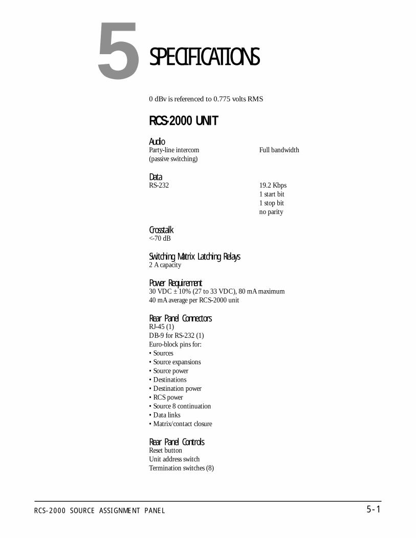
R C S - 2 0 0 0 S O U R C E A S S I G N M E N T P A N E L 5 - 1
SPECIFICATIONS
0 dBv is referenced to 0.775 volts RMS
RCS-2000 UNITAudioParty-line intercom Full bandwidth (passive switching)
DataRS-232 19.2 Kbps
1 start bit 1 stop bit no parity
Crosstalk<-70 dB
Switching Matrix Latching Relays2 A capacity
Power Requirement 30 VDC ± 10% (27 to 33 VDC), 80 mA maximum40 mA average per RCS-2000 unit
Rear Panel Connectors RJ-45 (1) DB-9 for RS-232 (1) Euro-block pins for: • Sources • Source expansions • Source power • Destinations• Destination power • RCS power • Source 8 continuation • Data links • Matrix/contact closure
Rear Panel ControlsReset button Unit address switch Termination switches (8)
5

R C S - 2 0 0 0 S O U R C E A S S I G N M E N T P A N E L5 - 2
Front Panel ConnectorRJ-45
Front Panel Controls Preset CodeLock/Unlock
Front Panel Indicators Double-digit, 8-segment LED readout LEDs for Power, Data, System Expansion, Fault, Lock
Dimensions 19 in. x 3.5 in. x 10.75 in. (48.3 cm x 8.9 cm x 27.31 cm)
Weight 5.5 lb. (2.5 kg)
RCS-2000 SYSTEM SizesSingle frame, 1x2, 2x1, 2x2, 1x3, 2x3
Maximum RCS-2000 Units 6 RCS-2000 units for a 15-source by 72-destination system
Storage 14 presets with labels (maximum size systems)Non-volatile memory System maintains all settings and switching matrix connections when powered off
Notice About SpecificationsWhile Clear-Com makes every attempt to maintain the accuracy of the information contained in its product manuals, that information is subject to change without notice. Performance specifications included in this manual are design-center specifications and are included for customer guidance and to facilitate system installation. Actual operating performance may vary.

R C S - 2 0 0 0 S O U R C E A S S I G N M E N T P A N E L 6 - 1
CLEAR-COM LIMITED WARRANTYThis product is guaranteed by Clear-Com Intercom Systems to be free of manufacturing defects in material and workmanship under normal use for two years from the date of purchase.
The Clear-Com Intercom Systems warranty does not cover any defect, malfunction, or failure caused beyond the control of Clear-Com, including unreasonable or negligent operation, abuse, accident, failure to follow instructions in the manual, defective or improperly associated equipment, attempts at modification and repair not authorized by Clear-Com, and shipping damage. Products with their serial numbers removed or defaced are not covered by this warranty.
This warranty is the sole and exclusive express warranty given with respect to Clear-Com products. It is the responsibility of the user to determine before purchase that this product is suitable for the user's intended purpose.
Any and all implied warranties, including the implied warranty of merchantability, are limited to the duration of this express limited warranty. Neither Clear-Com nor the dealer who sells Clear-Com products is liable for incidental or consequential damages of any kind.
For your own records fill in the information below:
Model No._____________________________Serial No.________________Date Purchased_________________________________________________Purchased from (dealer)___________________________________________Address_______________________________________________________City______________________________________State____ ZIP_________
FACTORY SERVICEAll equipment returned for repair must be accompanied by documentation stating the return address, telephone number, date of purchase, and a description of the problem.
Before returning equipment for repair, you must obtain a return authorization number. To obtain a return authorization number, call our customer service department at the number listed below. By talking with our representatives, many problems can often be resolved over the phone. You can also fax our customer service department or send an email to [email protected].
After obtaining a return authorization number, send equipment to be repaired to:
Customer Service DepartmentClear-Com Intercom Systems4065 Hollis Street Emeryville, CA 94608-3505Telephone: (510) 496-6666Fax: (510)496-6610Web site: www.clearcom.com
• Return authorization
numbers are required for
all returns.
• Both warranty and
non-warranty repairs are
available.
6

R C S - 2 0 0 0 S O U R C E A S S I G N M E N T P A N E L6 - 2
WARRANTY REPAIRIf in warranty, no charge will be made for the repairs. Equipment being returned for warranty repair must be sent prepaid and will be returned prepaid.
NON-WARRANTY REPAIREquipment that is not under warranty must be sent prepaid to Clear-Com. If requested, an estimate of repair costs will be issued prior to service. Once repair is approved and repair of equipment is completed, the equipment will be shipped freight collect from the factory.