instruction manual pyranometer ms-80 iso9060: 2018 class …
TRANSCRIPT

INSTRUCTION MANUAL
MS-80 MS-80S MS-80U
Pyranometer ISO9060: 2018 Class A Sub-category “Fast response” and ”Spectrally flat”

EKO INSTRUMENTS CO., LTD. - Pyranometer MS-80/80S/80U - Instruction Manual Ver. 1 Pg. 1
1. Index
1. Index 1
2. Important User Information 2
2-1. Contact Informat ion 2
2-2. Warranty and L iabi l i ty 2
2-3. About Ins truct ion Manual 3
2-4. Environment 3
2-5. ISO/IEC 17025 4
2-6. CE Declarat ion 5
3. Safety Information 7
3-1. General Warnings 7
4. Introduction 9
4-1. About the Pyranometer Ser ies 10
4-2. Field appl icat ions 12
4-3. Appl icat ion to the standards 12
4-3. Package Contents 13
5. Getting Started 14
5-1. Parts Name and Descr ipt ions 14
5-2. Setup 16
5-3. Wir ing 18
5-4. Connect ions 19
5-5. Measurements 27
6. Maintenance & Troubleshooting 31
6-1. Maintenance 31
6-2. Cal ibrat ion and Measurement Uncerta inty 33
6-3. Troubleshoot ing 34
7. Specifications 36
7-1. Speci f icat ions 36
7-2. Dimensions 38
7-3. Output Cables 40
7-4. Accessor ies L ist 41
APPENDIX 42
A-1. Radiometr ic Terms 42
A-2. Pyranometer Character ist ics 43
A-3. Software (Hib i) 44
A-4. Communicat ion Spec i f icat ions (Modbus RTU) 56
A-5. Communicat ion Spec i f icat ions (SDI -12) 68
A-6. About recal ibrat ion 70
A-7. Temperature sensor(10k ΩNTC, S/N: S19046150 or ear l ier) 71
A-8. MS-80 RTD Temperature Convers ion Table (Pt100 Class A) 72
A-9. MS-80S Set t ing report 73

EKO INSTRUMENTS CO., LTD. - Pyranometer MS-80/80S/80U - Instruction Manual Ver. 1 Pg. 2
2. Important User Information
Thank you for using EKO Products
Reading this manual is recommended prior to installation and operation of the product. Keep this manual in
a safe and handy place for whenever it is needed. For any questions, please contact us at below:
2-1. Contact Information
EKO INSTRUMENTS CO., LTD.
Asia, Oceania Region
https://eko-asia.com
EKO INSTRUMENTS Co., Ltd.
1-21-8, Hatagaya, Shibuya-ku
Tokyo, 151-0072 Japan
Tel: +81 [3] 3469-6713
Fax: +81 [3] 3469-6719
Europe, Middle East, Africa, South America Region
https://eko-eu.com
EKO INSTRUMENTS Europe B.V.
Lulofsstraat 55, Unit 28,
2521 AL, Den Haag, The Netherlands
Tel: +31 [0]70 3050117
Fax: +31 [0]70 3840607
North America Region
https://eko-usa.com
EKO INSTRUMENTS USA Inc.
111 North Market Street, Suite 300
San Jose, CA 95113 USA
Tel: +1 408-977-7751
Fax: +1 408-977-7741
2-2. Warranty and Liabi l i ty
For warranty terms and conditions, please contact EKO Instruments or your distributer for further details.
EKO guarantees that the product delivered to customer has been tested to ensure the instrument meets its
published specifications. The warranty included in the conditions of delivery is valid only if the product has been
installed and used according to the instructions provided in this operating manual.
In case any manufacturing defect[s] occurs, the defected part[s] will be repaired or replaced under warranty;
however, the warranty will not be applicable if:
Any modification or repair has been done by other than EKO service personnel.
The damage or defect is caused by disrespecting the specifications mentioned on the product brochure or
instruction manual.

EKO INSTRUMENTS CO., LTD. - Pyranometer MS-80/80S/80U - Instruction Manual Ver. 1 Pg. 3
2-3. About Instruct ion Manual
Copy Rights Reserved by EKO INSTRUMENTS CO., LTD. Making copies of whole or parts of this document
without permission from EKO is prohibited.
This manual was issued: Nov. 12, 2020
Version Number: 1
2-4. Environment
1. WEEE Directive 2002/96/EC [Waste Electrical and Electronic Equipment]
In August of 2005, the European Union [EU] implemented the EU WEEE Directive 2002/96/EC and later the
WEEE Recast Directive 2012/19/EU requiring Producers of electronic and electrical equipment [EEE] to
manage and finance the collection, reuse, recycling and to appropriately treat WEEE that the Producer places
on the EU market after August 13, 2005. The goal of this directive is to minimize the volume of electrical and
electronic waste disposal and to encourage re-use and recycling at the end of life.
EKO products are subject to the WEEE Directive 2002/96/EC. EKO Instruments has labeled its branded electronic
products with the WEEE Symbol [figure Trash bin] to alert our customers that products bearing this label should not
be disposed of in a landfill or with municipal or household waste in the EU.
If you have purchased EKO Instruments branded electrical or electronic products in the EU and are intending to
discard these products at the end of their useful life, please do not dispose of them with your other household or
municipal waste. Disposing of this product correctly will help save valuable resources and prevent any potential
negative effects on human health and the environment, which could otherwise arise from inappropriate waste
handling.
2. RoHS Directive 2002/95/EC
EKO Instruments has completed a comprehensive evaluation of its product range to ensure compliance with RoHS
Directive 2002/95/EC regarding maximum concentration values for substances. As a result all products are
manufactured using raw materials that do not contain any of the restricted substances referred to in the RoHS
Directive 2002/95/EC at concentration levels in excess of those permitted under the RoHS Directive 2002/95/EC,
or up to levels allowed in excess of these concentrations by the Annex to the RoHS Directive 2002/95/EC.

EKO INSTRUMENTS CO., LTD. - Pyranometer MS-80/80S/80U - Instruction Manual Ver. 1 Pg. 4
2-5. ISO/IEC 17025
EKO Instruments Co. Ltd. calibration laboratory is accredited by Perry Johnson Laboratory Accreditation, Inc. [PJLA]
to perform pyranometer and pyrheliometer calibrations in accordance with the requirements of ISO/IEC17025,
which are relevant to calibration and testing.
EKO is a manufacturer who can offer calibration service for pyranometers and pyrheliometers in-house. Based on
the applied calibration methods EKO provides the best quality solar sensor calibrations compliant to the international
standards defined by ISO/IEC17025 / 9847 [Indoor method] and ISO9059 [Outdoor method] [Certification: L13-94-
R2 / www.pjlabs.com]
ISO/IEC17025 provides a globally accepted basis for laboratory accreditation that specifies the management and
technical requirements. With calibrations performed at the EKO Instruments laboratory we enable our customers
to:
・ Clearly identify the applied calibration methods and precision
・ Be traceable to the World Radiation Reference [WRR] through defined industrial standards:
ISO9846 Calibration of a pyranometer using a pyrheliometer
ISO9847 Calibration of field pyranometer by comparison to a reference pyranometer
ISO9059 Calibration of field pyrheliometers by comparison to a reference pyrheliometer
・ Obtain repeatable and reliable calibration test results through consistent operations
Our clients will obtain highly reliable data by using an ISO/IEC17025 calibrated sensor. Our Accredited lab is
regularly re-examined to ensure that they maintain their standards of technical expertise.

EKO INSTRUMENTS CO., LTD. - Pyranometer MS-80/80S/80U - Instruction Manual Ver. 1 Pg. 5
2-6. CE Declarat ion
DECLARATION OF CONFORMITY
We: EKO INSTRUMENTS CO., LTD 1-
21-8 Hatagaya Shibuya-ku, Tokyo
151-0072 JAPAN
Declare under our sole responsibility that the product:
Product Name : Pyranometer
Model No. : MS-80, MS-80U
To which this declaration relates is in conformity with the following
harmonized standards of other normative documents:
Harmonized standards:
EN 61326-1:2006 Class A [Emission]
EN 61326-1:2006 [Immunity]
Following the provisions of the directive:
EMC-directive: 89/336/EEC
Amendment to the above directive: 93/68/EEC
Date: April 4, 2019
Position of Authorized Signatory: General Manager of R & D Department
Name of Authorized Signatory: Shuji Yoshida
Signature of Authorized Signatory:

EKO INSTRUMENTS CO., LTD. - Pyranometer MS-80/80S/80U - Instruction Manual Ver. 1 Pg. 6

EKO INSTRUMENTS CO., LTD. - Pyranometer MS-80/80S/80U - Instruction Manual Ver. 1 Pg. 7
3. Safety Information
EKO Products are designed and manufactured with consideration for safety; however, please make sure
to read and understand this instruction manual thoroughly to be able to operate the instrument safely in
the correct manner.
WARNING CAUTION
Attention to user; pay attention to the instructions given on the
instruction manual with this sign.
HIGH VOLTAGE WARNING
High voltage is used; pay special attention to instructions given on
this instruction manual with this sign to prevent electric leakage
and/or electric shocks.
3-1. General Warnings
1. Setup The installation base or mast should have enough load capacity for the instrument to be mounted. Fix
the pyranometer securely to the base or mast with bolts and nuts; otherwise, the instrument may drop
due to a gale or an earthquake, which may lead to unexpected accidents.
Make sure to install the instrument and cables in a suitable location, and avoid submersion in water.
When using this instrument by connecting to a measuring instrument, make sure to connect the shield
cable to either the signal ground terminal on the measuring instrument side or GND [the reference
potential on the single end input side]. Noises may be included in the measurement data.
Although this product is tested to meet EMC Directive compliance requirements, it may not fully satisfy
its primary specification/performance when using this product near following locations where strong
electromagnetic wave is generated. Please pay attention to the installation environment.
Outdoor: High voltage power line, power receiver/distribution facility, etc.
Indoor: Large-size chiller, large rotation device, microwave, etc.
Do not use this product in the environment where corrosive gas, such as ammonia and sulfurous acid
gas, are generated. It may cause malfunction.
Do not install in the area that cause salt damages. It may cause malfunction by paint peeling off or
corrosion. When installing in the area with risk of salt damages, make sure to take following measures:
1. Wrap the connector with self-fusing tape
2. Change the fixing screw to bolt screw made of aluminum
3. Run the cables in a plastic or metal pipe treated with salt-resistant paint such as molten zinc plating
4. Periodically clean.
Do not use this instrument in the vacuum environment.
For proper grounding use the original cable provided.

EKO INSTRUMENTS CO., LTD. - Pyranometer MS-80/80S/80U - Instruction Manual Ver. 1 Pg. 8
If the cable and main unit are in risk for getting damaged by birds and small animals, protect the cable
and the main unit by using:
1. Reflective tape
2. Repellent
3. Cable duct
4. Installing bird-spike
When using the configurable 0 to 1V output from MS-80S, please use a precision resistor 100Ω. The
settings can be changed with the 485 / USB conversion cable and dedicated software.
2. Handling
Be careful when handling instruments with glass domes. Strong impact to this part may damage the
glass and may cause injuries by broken glass parts.
When carrying any MS-80 model with the sunscreen attached, always hold the instrument from the
bottom. Holding only the sunscreen part may lead to dropping the sensor as it comes off from the
sunscreen.
For voltmeters, data loggers, etc. to be measured by connecting to MS-80, MS-80U, use a product with
an input resistance of 100MΩ or more.
3. Signal Cable [MS-80S] Make sure to ground the signal cable. When grounding is insufficient, it may cause not only
measurement error due to noise, but also cause electric shock and leakage accidents.
Check the voltage and types of specified power supply before connecting this instrument. When
improper power supply is connected, it may cause malfunction and/or accident.
Use this instrument with 0.5A fuse connected to the power supply line in series. Without connecting the
fuse, it has risks of generating heat and fire due to large-current flowing by the power supply when
internal damage of the electronics occurs.
4. About RS-485 Modbus connection [MS-80S] This product supports communication through the RS-485 Modbus RTU.
It is recommended to use the optional EKO converter cable when connecting MS-80S to a PC..
Depending on the USB-RS485 converter type, an additional termination resistor (120Ω) and/or pull-
up/pull-down resistor (680Ω) is required for proper communication.
When connecting to a RS-485 (Modbus) master peripheral device, an additional termination resistor
(120Ω) and/or pull-up/pull-down resistor (680Ω) is required for proper communication.

EKO INSTRUMENTS CO., LTD. - Pyranometer MS-80/80S/80U - Instruction Manual Ver. 1 Pg. 9
4. Introduction
EKO’s new generation sensor, the MS-80 broke with the rules of traditional pyranometer architecture. The innovative
design was inspired by the combination of latest technologies and state-of-the-art thermopile sensor, enabling a
breakthrough in unprecedented low zero-offset behaviour, fast sensor response, high accuracy and over time
measurement stability. MS-80 remains a class-leader for ISO 9060:2018 Class A solar sensors today. It offers several
advantages over the competition to perform the most accurate irradiance measurements against low cost of ownership.
The compact sensor with single dome is immune to thermal offsets and integrates all value-added functions to reduce
maintenance. MS-80 pyranometer no longer have a drying cartridge, silica gel inside will keep the sensor dry.
The MS-80S has integrated Smart electronics providing advanced measurement functions. With 4 different industrial
signal outputs (Modbus 485 RTU, configurable SDI-12, 4-20mA, configurable 0-10mA and 0-1V with external precision
shunt resistor 100Ω). Combined with on-board sensors for remote diagnostics of the sensor temperature, relative
humidity and tilt position.
For the MS-80 series a range of accessories is available (MV-01 ventilator and heater, cable extensions and albedo
mounting plates).
MS-80 unique properties:
Long term stability Compared to our conventional pyranometer, the long-term stability is further enhanced with improved
airtightness and the sensor architecture with low sensitivity degradation properties.
Fast detector response The MS-80 series is based on the latest thermopile technology, with a response time of <0.5sec
@95% or <1sec @99% for all models (ISO 9060:2018 Class A, Sub-category “Fast response” and “Spectrally flat”). Such
response time is suitable for measuring solar irradiance, which changes momentarily.
Excellent temperature coefficient MS-80 has a extremely low temperature error in wide temperature range compared
to most conventional pyranometers, and it provides linear output against solar irradiance.
Lowest zero off-set Compared to any conventional pyranometers with double-domes, additional ventilation and heating
system. MS-80 has the lowest off-set error designed intrinsically to the concept. The combination of the isolated
thermopile detector architecture and optics keep the sensor in thermal balance within variable atmospheric conditions.
Warranty and re-calibration Unique in the market the MS-80 has 5 years warranty and 5 years recommended re-
calibration period due to the great long term stability of the detector.
ISO 9060:2018 The international industry standard for pyranometer classification, was revised to the 2nd edition in 2018.
Along with this revision, pyranometers are classified in order of the highest grade "Class A", "Class B", "Class C" and for
Pyranometers that meet the response time and spectral selectivity criteria, "fast response" and "spectrally flat" are
classified as a sub-category. MS-80, MS-80S and MS-80U are class A pyranometer that meets the subcategory of "fast
response and spectrally flat".

EKO INSTRUMENTS CO., LTD. - Pyranometer MS-80/80S/80U - Instruction Manual Ver. 1 Pg. 10
4-1. About the Pyranometer Series
EKO offers three different MS-80 pyranometer models each with different features. With this wide range of sensors,
EKO pyranometers can meet all possible application requirements, ranging from PV module efficiency
measurements to climatology research and material durability testing.
All MS-80 sensors give excellent durability. The sensor is airtight and can be deployed with little maintenance
since the desiccant is incorporated inside. Solar sensors are applied outdoors, hence the detector black surface,
optical components and sensor mechanics are constantly exposed to solar radiation, temperature and pressure
differences. UV radiation known as harmful radiation to materials can change the chemical properties of
substances irreversibly. In the case of the MS-80, the detector is totally isolated below the sensor optics surface,
which is sealed, and can’t be affected by a high dose of UV, moisture or pressure differences.
During production and inspection, the directional response and temperature dependency are measured and
validated through a measurement report that comes with each sensor. Besides, EKO provides a unique
calibration service for pyranometers compliant to the international standards defined by ISO/IEC17025 / 9847
[indoor method]. When an ISO/ IEC17025 calibrated sensor is purchased, EKO provides a calibrated sensor with
a consitently low calibration uncertainty. The Accredited lab is regularly re-examined to ensure that they maintain
their standards of technical expertise.
A setting report is provided with all parameters which were set and tested during manufacturing (current range
settings, digital output communication settings, tilt position calibration, relative humidity and sensor temperature).
In case of MS-80, MS-80S, with combination of optional MV-01 [ventilator + heater unit], reduces the dew
condensation and accumulation of dusts and snow on glass dome by continuously blowing heated air. The
ventilation unit with heater is recommended when the sensor is deployed with a chance of occurance of
condensation, snow and ice. IEC 61724-1 Class A monitoring systems should use the MS-80 series pyranometer
with the MV-01 which has a minimum <2W power consumption.
In the following paragraphs, the three instrument types are described individually.
1. MS-80 The analog MS-80 pyranometer can be used as a reference sensor to measure the global broad-band solar
radiation with a high accuracy thermopile sensor. With excellent temperature response and non-linearity
characteristics, it provides optimal performance throughout the day.
Category of ISO9060: 2018
“Fast response and spectrally flat pyranometer of class A”
Key features:
• Response time [<0.5s@95%, <1s@99%]
• Excellent temperature response over a wide temperature range [-20 to +50]
• Low offset characteristics
• 5 Year warranty and recalibration period

EKO INSTRUMENTS CO., LTD. - Pyranometer MS-80/80S/80U - Instruction Manual Ver. 1 Pg. 11
2. MS-80S The MS-80S with smart sensor technology and onboard diagnostic functions. 4 different output types can be
selected, which is a great benefit for system integrators who work with various industrial standards. This new
Smart transducer will also have additional features such as internal temperature and humidity sensors and a tilt
sensor for remote sensor diagnostics. These additional internal sensors will help the user to monitor the stability
of the irradiance sensors as well as to ensure its proper installation and maintenance practices.
Up to 31 smart sensors per one Master can be connected in one network. The signal converter settings can be
changed using the optional RS485 / USB converter cable and the configurator software.
Category of ISO9060: 2018
“Fast response and spectrally flat pyranometer of class A”
Key features:
• Response time [<0.5s@95%, <1s@99%]
• Excellent temperature response over a wide temperature range [-20 to +50]
• Low offset characteristics
• 5 Year warranty and recalibration period
• Outputs (Modbus 485 RTU, configurable SDI-12, 4-20mA, configurable 0-10mA / 0-1V with external 100Ω
precision shunt resistor)
• Low power consumption
• Wide voltage-supply input range [5 to 30 VDC]
• With built-in tilt / roll sensor to check the sensor position over time.
• Humidity and ttemperature sensor to monitor the sensor temperature and condition of the drying agent (silica
gel) inside the sensor body.
3. MS-80U MS-80U is the most compact and light-weight ISO 9060:2018 Class A pyranometer on the market. With a total
weight of only 200 grams and low body height the sensor can be easily used for drone and UAV applications. The
body is hermetically sealed and can be used in environments up to 15 km above sea level. The sensor temperature
characteristics are optimized for the lower part of the temperature range.
Category of ISO9060:2018
“Fast response and spectrally flat pyranometer of class A”
Key features:
• Compact and light weight
• Response time [<0.5s@95%, <1s@99%]
• Excellent temperature response over a wide temperature range [-20 to +50]
• Low offset characteristics
• 5 Year warranty and recalibration period

EKO INSTRUMENTS CO., LTD. - Pyranometer MS-80/80S/80U - Instruction Manual Ver. 1 Pg. 12
4-2. Field appl icat ions
MS-80 is made for accurate irradiance measurements in the field of solar energy and meteorological research. The
MS-80 analog sensor is well suited to be used in traditional meteorological networks where analog sensors are still
common. MS-80S with the Smart interface with multiple outputs is made for the solar energy industry to be used in
different applications. For PV research, plant monitoring and SCADA (Supervisory Control and Data Acquisition)
controlled systems. The MS-80S with digital (Modbus 485 RTU / SDI-12) can be used in a multi sensor network for
onsite monitoring of large PV plants. Digital sensor can be easily configured, With the MS-80S, users can connect
using a standard laptop and ‘Hibi’; a new, custom built programme developed by EKO to give users real-time access
to the internal diagnostics, custom settings, and data on irradiance, humidity, internal temperature and tilt angle
from the sensor. This data can also be acquired when the pyranometer is connected through the data logger digital
serial communication port. Each pyranometer has it own unique communication address. This way multiple
pyranometers can be connected in a network.
The MS-80S builds on the revolutionary qualities of the original MS-80 by adding a new internal diagnostics system,
giving users remote visibility over body temperature, internal humidity, tilt and roll angle; helping them to ensure
optimum performance without the need for regular physical checks. Coupled with the 5-year recalibration interval,
the internal diagnostic capabilities of the MS-80S makes it an ideal solution for complex networks, hard to reach
locations, and monitoring stations with restricted access.
4-3. Appl icat ion to the standards
MS-80 models are qualified to be used within any application which refers to an international standard according
to:
• ISO9060: 2018 Fast response and spectrally flat pyranometer class A (Pyranometer classification)
• EC 61724-1:2017 Class A (PV monitoring system requirement)
• ASTM 2848-11 (Test Method for Reporting Photovoltaic Non-Concentrator System Performance)
• WMO-No. 8, seventh edition 2008 High quality pyranometer (Meteorological system requirement)
• ISO/TR 9901:1990 (Solar energy field pyranometers recommended practice for use)
• ASTM G183 - 05 (Standard Practice for Field Use of Pyranometers)
MS-80 models comply to the international standards for calibration and traceable to the WRR:
• ISO 9847 Calibration of field pyranometers by comparison to a reference pyranometer
• ISO 9846 Calibration of a pyranometer using a pyrheliometer
• ISO 17025 scope of accreditation [Certification: L13-94-R2 / www.pjlabs.com]

EKO INSTRUMENTS CO., LTD. - Pyranometer MS-80/80S/80U - Instruction Manual Ver. 1 Pg. 13
4-3. Package Contents
Check the package contents first; if any missing parts or any damage is noticed, please contact EKO immediately.
Table 4-1. Package Contents
Contents MS-80 MS-80S MS-80U
Pyranometer
Output Cable (1) (1) (2)
Sunscreen x
Calibration Certificate
Instruction Manual Not included in the package
[Please download from EKO Website]
Setting Report x (3) x
Calibration certificate
Cosine response report
Temperature dependency
report
Quick Start Guide x
Hibi software Windows PC Software to change settings, sensor diagnostics, data
collection
Fixing Bolts [ M5 ] x2
[Bolt Length: 75mm ]
Washers [ M5 ] x4
Nuts [ M5 ] x2
(1) In case of MS-80/80S, standard length is 10m for both signal/power cable. For different length of cables [e.g. to
meet your application needs] please contact EKO or your local distributor.
(2) MS-80U cable length is 3m, no other optional lengths are available. The cable is not detachable from the body.
(3) Details about the setting report, see appendix A-9.

EKO INSTRUMENTS CO., LTD. - Pyranometer MS-80/80S/80U - Instruction Manual Ver. 1 Pg. 14
5. Getting Started
5-1. Parts Name and Descript ions
Each part name and its main function is described below.
Parts Name
A. Diffuser
B. Glass Dome
C. Detector
D. Body
E. Sun screen
F. Levelling Screw
G. Cable, Connector
H. Spirit Level
I. Knurling Screw
J. Detector temperature
sensor
K. Internal temperature
sensor
Parts Name
A. Diffuser
B. Glass Dome
C. Detector
D. Body
E. Levelling Screw
F. Cable
G. Spirit Level
MS-80 / MS-80S
MS-80U
*The cable can’t be removed from the pyranometer
Figure 5-2. Pyranometer Parts Name [MS-80U]
Table 5-1. Parts Name
[MS-80 / MS-80S]
Table 5-2. Parts Name
[MS-80U]
*Signal converter is built-in for MS-80S.
Figure 5-1. Pyranometer Parts Name [MS-80 / 80S]
J
K

EKO INSTRUMENTS CO., LTD. - Pyranometer MS-80/80S/80U - Instruction Manual Ver. 1 Pg. 15
1. Glass Dome, Quartz Diffuser A glass dome creates a sealed environment for the detector and protects it against dirt and rain. The dome of the
EKO pyranometers is only transparent for radiation emitted by the sun. The combination of the glass dome and
the Quartz diffuser give a 180 degrees field of view and cosine response.
2. Detector The thermopile detector, which is the heart of the pyranometer generates a voltage signal that is proportional to the
solar irradiance. The fast response detector has a low temperature dependency and excellent long term stability.
3. Sunscreen, Body and Spirit level MS-80 and MS-80S have a sunscreen to prevent any excessive body temperature increase generated by direct
sun light.Weather resistant metals are used to reduce the effects and degradation caused by heat radiation, rain,
and windblown dusts. The integrated spirit level is used for setup and maintaining the sensor in a horizontally
levelled position.
4. Drying agent Enclosed drying agents inside the sensor body keep the sensor inside dry, prevents condensation of humidity inside
of the glass dome.
5. Cable and Cable Connector MS-80/ 80S are shipped with a 10 meter long output cable as standard length*.
Durable materials are used for the cable and connector, and pin terminals are attached at the end of the cable for
easy connection with a data logger terminal block.
* If longer cables, round terminals or fork terminals are required, please contact EKO Instruments or your
distributor. [Also see [7. Specification, 7-4. Accessories List] for optional items.]
The connector should be protected by the self-fusing tape when the pyranometers are used in the areas with
the risk of the salt damage.
MS-80U has a 3 meter long output cable already attached, and the leads of the cable are soldered.

EKO INSTRUMENTS CO., LTD. - Pyranometer MS-80/80S/80U - Instruction Manual Ver. 1 Pg. 16
5-2. Setup
In order to obtain high quality measurements from pyranometers, several criteria with respect to setup and mounting
of the instruments have to be considered. Also see the Quick Start Guide for comprehensive setup instruction details
[included in the package of MS-80, MS-80S].
The ideal mounting position for a pyranometer is a location which has a full hemispheric field-of-view without any
obstructions [such as buildings, trees, and mountains]; however, it might be difficult to find such locations. Therefore
in practice, it is ideal to install in a position which is free from obstructions at 5° above horizon.
The setup location should be easily accessible for periodic maintenance [glass dome cleaning], and avoid
surrounding towers, poles, walls or billboards with bright colors that can reflect solar radiation onto the pyranometer.
A strong physical impact to the pyranometer can lead to product damage and/or may cause changes to the
sensitivity.
1. Installing at Horizontal or Tilted Position
1) Check the installation base where the pyranometer has to be mounted and make sure it has two fixing holes
with the appropriate pitch. The pitch sizes of the fixing holes are as follows [in mm]:
Table 5-3. Fixing Hole Pitch and Bolt Size for Pyranometers
MS-80 / MS-80S / MS-80U
Fixing Hole Pitch 65 mm
Fixing Bolt Size M5 x 75 mm
2) Remove a sunscreen [except for MS-80U]
The sunscreen can be removed by loosening the knurling screw and sliding it towards the spirit level direction.
*When carrying MS-80 or MS-80S with a sunscreen attached, always hold the instrument from the bottom.
Holding only the sunscreen may lead to dropping the sensor as it comes off from the sunscreen.
3) There are two ways to setup the pyranometer (Horizontal or inclined).
Installing at horizontal Position
Setup the pyranometer with the signal cable connector facing the nearest Earth’s pole. In the Northern
hemisphere, the connector should be orientated North, in the Southern hemisphere, the connector should be
orientated South. Adjust the pyranometer in a horizontal position by using the 2 levelling screws observing the
air bubble in the spirit level while manipulating the levelling screws. The instrument is levelled horizontally if
the air bubble is in the centre ring. The sensitivity of the bubble vial is (0.1º / mm). If the pyranometer is not
levelled properly, the pyranometer readings are affected by cosine and azimuth errors. Periodically check the
spirit level and adjust the pyranometer’s position if necessary.

EKO INSTRUMENTS CO., LTD. - Pyranometer MS-80/80S/80U - Instruction Manual Ver. 1 Pg. 17
Installing at an inclined angle
After the MS-80, MS-80S or MS-80U is adjusted to horizontal position in levelled surface, install it on tilted a
tilted mount.
When installing the pyranometer, do not remove the levelling feet or fixed feet. If the levelling
feet are removed, it may induce offsets to output values due to the thermal effects from the
mounting plate.
In the case of MS-80S, it is possible to acquire tilt
information obtained from the built-in tilt position
sensor through Modbus RTU. The sensor position
can be measured in two different planes (X,Y).
<Tilt (X axis)> (90º to 0) and (0 to -90º)
<Roll (Y axis)> (90º to 0) and (0 to -90º)
The tilt and roll angles are relative to the calibrated X and Y axis of the sensor and surface mounting plane X’
and Y’. When the sensor is positioned in the same plane X = X’ and Y = Y’, the measured tilt and roll angles
(X and Y) correspond to plane of installation X’ and Y’.
The pyranometer connector is an important reference for setup and corresponds to the X-
axis reference plane.
For setup at horizontal plane: Setup the pyranometer with the signal cable connector facing
the nearest Earth’s pole. In the Northern hemisphere, the connector should be orientated
North, in the Southern hemisphere, the connector should be orientated South. If the cable is
not oriented to the nearest pole, it does not affect the angle measurement. The angle
measurement reflects the tilt and roll of the corresponding sensor position.
For setup at inclined plane: Setup the pyranometer with signal cable aligned with the
installation platform (X’, Y’), see figure 5-3B. When the sensor is not aligned, the tilt (X) and
roll (Y) measurement does not reflect the angle X’ and Y’, see figure 5-3C.
4) Fasten the pyranometer to the base with the 2 bolts [included] and put the sunscreen back on the pyranometer.
+Y
-X
X’
Y’
-Y
+X
X’
Y’
Figure 5-3B Tilt and roll angle
corresponding to reference plane
Figure 5-3C Tilt and roll angle not
corresponding to reference plane
Figure 5.3A Tilt angle (-90 to 0º) and (0 to 90º)
Roll angle (-90 to 0º) and (0 to 90º)
-X X
Y -Y
EKO INSTRUMENTS CO., LTD. - Pyranometer MS-80/80S/80U - Instruction Manual Ver. 1 Pg. 18
5-3. Wiring
To extend the cable lifetime, make sure that the cables are not exposed to direct sun light or rain/wind by lining the
cable through a cable conduit. Cable vibrations will potentially cause noise in the output signal. Fasten the cable so
that the cable does not swing or move by wind blowing. Exposure of the signal cable to excessive electromagnetic
emissions can cause noise in the output signal as well. Therefore, the cable should be lined at a safe distance from
a potential source generating EMC noise, such as an AC power supply, high voltage lines or telecom antenna.
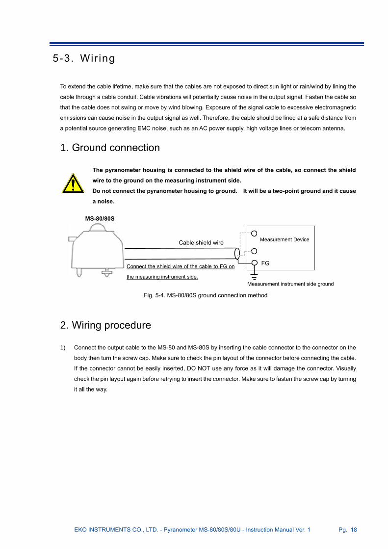
1. Ground connection
The pyranometer housing is connected to the shield wire of the cable, so connect the shield
wire to the ground on the measuring instrument side.
Do not connect the pyranometer housing to ground. It will be a two-point ground and it cause
a noise.
2. Wiring procedure
1) Connect the output cable to the MS-80 and MS-80S by inserting the cable connector to the connector on the
body then turn the screw cap. Make sure to check the pin layout of the connector before connecting the cable.
If the connector cannot be easily inserted, DO NOT use any force as it will damage the connector. Visually
check the pin layout again before retrying to insert the connector. Make sure to fasten the screw cap by turning
it all the way.
Cable shield wire
FG
Measurement Device
Measurement instrument side ground
Connect the shield wire of the cable to FG on
the measuring instrument side.
MS-80/80S
Fig. 5-4. MS-80/80S ground connection method

EKO INSTRUMENTS CO., LTD. - Pyranometer MS-80/80S/80U - Instruction Manual Ver. 1 Pg. 19
5-4. Connect ions
The MS-80 and MS-80U have an analog output for irradiance and detector temperature measurements. The MS-
80S is based on a digital Smart processing interface providing advanced measurement functions with 4 different
industrial signal outputs (Modbus 485 RTU, configurable SDI-12, 4-20mA, configurable 0-10mA and 0-1V with
external precision shunt resistor 100Ω).
Table 5-5. Pyranometer outputs
Output MS-80 MS-80S MS-80U
Analog (mV) x
Modbus 485 RTU (Default) x x
SDI-12 x x
4 - 20 mA (Default) x x
0 - 10 mA x x
0 - 1V x (*) x
(*) MS-80S 0-10mA output with external precision shunt resistor 100Ω
Table 5-6. Pyranometer output parameters
Output parameters MS-80 MS-80S MS-80U
Irradiance
Temperature (*)
Tilt position x (*) x
Relative humidity x (*) x
Sensor information x (*) x
(*) MS-80S digital output (Modbus 485 RTU / SDI-12)

EKO INSTRUMENTS CO., LTD. - Pyranometer MS-80/80S/80U - Instruction Manual Ver. 1 Pg. 20
1. Analog output
The MS-80 and MS-80U have an analog output for irradiance and detector temperature.
• Use a measuring device with an input impedance of 100MΩ or more. Low input
impedance may cause underestimation of the output voltage measured.
• Be sure to connect the cable shield to the frame ground of the measurement device,
otherwise noises may occur.
A. MS-80 (from S/N: S19046151, temperature sensor 3W Pt100 class A). Connect the 5 wires with corresponding
color to the input terminals of the voltmeter or data logger (figure 5-5).
[*] Always connect the shield cable to prevent signal noise. [**] See the Appendix A-8 resistance to temperature conversion table [PT-100].
B. MS-80 (Till S/N: S19046150, temperature sensor type NTC 10kΩ). Connect the 4 wires with corresponding
color to the input terminal sof the voltmeter or data logger (figure 5-6).
[*] Always connect the shield cable to prevent signal noise.
[**] See the Appendix A-7 resistor to temperature conversion table. [NTC 10k Ω].
Brown
White
Blue
Black
Gray
Shield
+ Measurement
Device -
Pt100 [B]
Pt100 [B] Ω[**]
Pt100 [A]
FG [*]
Fig. 5-5. How to connect MS-80 (from S/N: S1904615)
Fig. 5-6. How to connect MS-80 (Till S/N: S19046150)
+ Measurement
Device -
FG [*]
NTC
NTC Ω[**]
Brown
White
Blue
Shield

EKO INSTRUMENTS CO., LTD. - Pyranometer MS-80/80S/80U - Instruction Manual Ver. 1 Pg. 21
C. MS-80U (Temperature sensor type NTC 10kΩ). Connect the 4 wires with corresponding color to the input
terminals of the voltmeter or data logger (figure 5-7).
[*] Always connect the shield cable to prevent signal noise.
[**] See the Appendix A-7 resistor to temperature conversion table. [NTC 10k Ω].
2. Current output (4-20mA / 0-10mA)
MS-80S has two current outputs (4-20mA and 0-10mA). The 4-20mA output is default, the 0-10mA output can be
enabled through the “Hibi” software which can be downloaded from the EKO website (MS-80S product page). See
appendix 3 to change the current output settings. The current output can be converted into a voltage output when
a shunt resistor is used in series. In combination with an external 100Ω precision resistor (0.1%, 15 ppm) a 0-1V
output can be made.
Current output (4-20mA / 0-10mA)
Connect the 3 wires with corresponding color to the input terminals of the current meter or data logger (figure 5-8).
Connect the power terminals to a DC power supply [8 to 30 V]. We recommend to use a fuse [0.5A] to the DC power
supply line [+] for over current protection.
Interconnect the power supply (-) and 4-20mA / 0-10mA (-) line. The MS-80S current output
requires a 3 wire connection, contrary to the 2 wire configuration of MS-80A which is
current loop.
Fig. 5-7. How to connect MS-80U
Red
White
Green
Black
Shield
[Ω] [***]
+ Measurement
Device
-
FG [*]
NTC
NTC
Fig. 5-8. How to connect MS-80S (4-20mA / 0-10mA output)
Brown
Power supply
DC8V to 30V
-
+
4-20mA input
Measurement Device
+
-
Fuse [0.5A]
White
Gray
Shield

EKO INSTRUMENTS CO., LTD. - Pyranometer MS-80/80S/80U - Instruction Manual Ver. 1 Pg. 22
Voltage output (0-1V)
The current output can be converted into a voltage output when a shunt resistor is used in parallel. The default
output is 4-20mA. The 0-10mA (0-1V) output is disabled. The settings can be changed when the MS-80S is
connected to a PC through the Hibi software, see appendix 3 for instruction.
Connect the 3 wires with corresponding color to the input terminals of the Voltmeter or data logger (figure 5-9).
Connect the power terminals to a DC power supply [8 to 30 V]. We recommend to use a fuse [0.5A] to the DC power
supply line [+] for over current protection. The precision shunt resistor (0.1%, 15 ppm) need to be placed across the
voltage input terminals of the measurement device.
Interconnect the power supply (-) and 4-20mA / 0-10mA (-) line. The MS-80S current output
requires a 3 wire connection, contrary to the 2 wire configuration of MS-80A which is
current loop.
When a precision shunt resistor (0.1%, 15ppm) is used in combination with the 4-20mA output it is
required to match the precision shunt resistor value with supply Voltage to compensate for the
voltage drop across the shunt resistor. (See the Table 5-7. )
Table 5-7. Shunt resistor value at supply voltage
Supply voltage Shunt resistor value
8VDC to 15VDC 100Ω to 250Ω
15VDC to 24VDC 250Ω to 500Ω
24VDC to 30VDC 500Ω
Power supply
DC 8V to 30V
-
+
0 to 1V input
Voltmeter
+
- Fuse [0.5A]
R
Brown
White
Gray
Shield
Fig. 5-9. How to connect MS-80S (0-1V output)

EKO INSTRUMENTS CO., LTD. - Pyranometer MS-80/80S/80U - Instruction Manual Ver. 1 Pg. 23
3. Digital output (Modbus / SDI-12)
The MS-80S can work in two digital output modes, respectively Modbus 485 RTU and SDI-12. Modbus 485 output
is set to default, the SDI-12 output can be selected through the Hibi software.
PC connection (Modbus)
For any converter with screw terminals or open wires, connect the 4 wires of the sensor cable with the corresponding
wire color to the RS-485 to USB converter (figure 5-10). Some converter cables provide a 5V supply voltage from
the USB port, in such case no additional power supply is required. In any other case use an additional power supply.
Connect the power terminals to a DC power supply [8 to 30 V]. We recommend to use a fuse [0.5A] to the DC power
supply line [+] for over current protection.
* For stable communication, please connect the minus of
the power supply and the GND of RS485/USB converter.
Depending on the converter type and design properties, some commercial RS-485 to USB
converters may not work properly. A termination resistor is required to prevent reflections from
the end of the transmission line. Pull-up and pull-down resistors are necessary to keep the voltage
level constant when the transmission line is in a high impedance state.
EKO can provide an optional and approved USB converter for connection with a PC. The converter
cable is needed for setup , sensor diagnostics and data logging through the Hibi software.
Depending on your region, the optional converter can be different.
Fig. 5-10. How to connect MS-80S (Modbus RS485)
Brown
White *
Blue
Black
Shield
Power supply
DC5V, or 8 to 30V
TR+ / A
TR- / B
RS485/USB
Converter
+
-
Fuse [0.5A]
PC
GND

EKO INSTRUMENTS CO., LTD. - Pyranometer MS-80/80S/80U - Instruction Manual Ver. 1 Pg. 24
Data logger connection (Modbus)
Connect the 4 wires of the sensor cable with the corresponding wire color to the RS-485 communication port of the
data logger master and power supply unit (figure 5-11). Connect the power terminals to a DC power supply [8 to 30
V]. We recommend to use a fuse [0.5A] to the DC power supply line [+] for over current protection.
MS-80S can be configured within a multi sensor RS-485 Modbus communication network. Up to 31 sensors per
one Master can be connected and be assigned with a unique address. For a multiple sensor network the sensors
need to be configured according to the recommended RS-485 configuration standards as shown in figure 5-12.
The master represents the data-logging device and slaves represent devices such as MS-80S or other serial
devices in the same network. Connect the communication wires of the slave to the modbus communication input of
the master. Connect a 120Ω termination resistor at the end of the communication line. The master device may have
an integrated termination resistor and pull-up and pull-down resistors. If any communication issues occur, apply
those separately.
Figure 5-12. Communication Connection with Modbus RTU
Apply a Termination resistor (typically 120 to 150Ω) : Typically reflections occur on long lines, resulting
in a receiver misreading logic levels. Proper termination prevents reflections, improving data integrity.
Apply Pull-up and pull-down resistors (typically 680 to 850Ω): Necessary to keep the voltage level
constant when the transmission line is in a high impedance state.
Communication errors may occur depending on the connection distance and the number of
connections. In that case, please prepare and apply a RS485 booster or a repeater.
Communication problems may occur if Modbus and SDI-12 are used at the same time.
Fig. 5-11. How to connect MS-80S (Modbus RS-485)
Brown
White
Blue
Black
Shield
Power supply
DC8 to 30V
+
-
Data logger
RS-485 Modbus
-
Fuse [0.5A]
+
EKO INSTRUMENTS CO., LTD. - Pyranometer MS-80/80S/80U - Instruction Manual Ver. 1 Pg. 25
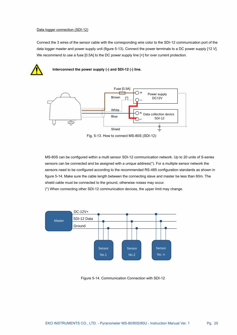
Data logger connection (SDI-12)
Connect the 3 wires of the sensor cable with the corresponding wire color to the SDI-12 communication port of the
data logger master and power supply unit (figure 5-13). Connect the power terminals to a DC power supply [12 V].
We recommend to use a fuse [0.5A] to the DC power supply line [+] for over current protection.
MS-80S can be configured within a multi sensor SDI-12 communication network. Up to 20 units of S-series
sensors can be connected and be assigned with a unique address(*). For a multiple sensor network the
sensors need to be configured according to the recommended RS-485 configuration standards as shown in
figure 5-14. Make sure the cable length between the connecting slave and master be less than 60m. The
shield cable must be connected to the ground, otherwise noises may occur.
(*) When connecting other SDI-12 communication devices, the upper limit may change.
Figure 5-14. Communication Connection with SDI-12
SDI-12 Data
DC-12V+
Ground
Sensor
No.1
Sensor
No.2
Sensor
No. n
Master
Interconnect the power supply (-) and SDI-12 (-) line.
Fig. 5-13. How to connect MS-80S (SDI-12)
Brown
White
Blue
Shield
Power supply
DC12V
+
- Data collection device
SDI-12
+
-
Fuse [0.5A]
[*]

EKO INSTRUMENTS CO., LTD. - Pyranometer MS-80/80S/80U - Instruction Manual Ver. 1 Pg. 26
4. Overview wire assignments
Table 5-7. Wire Color Codes of MS-80 and MS-80U (Also see [7-3. Output Cables])
Table 5-8. Color Codes of cable of MS-80S
[*] When selecting 0-1V output, a precision resistor is required separately.
No. Cable Color
MS-80 MS-80U MS-80 MS-80U
1. Brown Red mV [+] mV [+]
2. White White mV [-] mV [-]
3. Blue Green Pt100 [B] NTC
4. Black Black Pt100 [B] NTC
5. Gray - Pt100 [A] ---
Shield Shield Shield FG FG
No. Wire Color 4-20mA Modbus SDI-12 0-1V [*]
1. Brown (+) 8 to 30VDC (+) 5 to 30VDC (+) 12VDC (+) 8 to 30VDC (+)
2. White (-) 4~20mA (-)
/ GND
Vcc GND
/ RS485 GND Vcc GND
0~10mA (-)
/ 0-1V (-) / GND
3. Blue (+) --- RS485 (+) SDI-12 Data (+) ---
4. Black (+) --- RS485 (-) --- ---
5. Gray (+) 4~20mA (+) --- --- 0~10mA (+)
/ 0-1V (+)
Shield Shield FG FG FG FG
Figure 5-15. Connector pin number of MS-80 and MS-80S
Each number corresponds to the number in Table 5-7 and Table 5-8. There is no corresponding figure for MS-80U because the cable can’t be removed from MS-80U body.

EKO INSTRUMENTS CO., LTD. - Pyranometer MS-80/80S/80U - Instruction Manual Ver. 1 Pg. 27
5-5. Measurements
1. Data logger settings
The output voltage is measured by a measuring device such as a voltmeter or a data logger. If solar irradiance
is measured continuously, it is recommended to use a data logger, which has sufficient memory to record data
over a longer period and functions to process the measurement parameters of the pyranometer. Depending
on the sensor output which will be used, the data logger should be capable to measure the assigned output
type.
For MS-80 with analog output, the data logger should have a voltage input range (0-20mV), resolution (~1µV )
and impedance (> 100MΩ). For the MS-80S with current output, Modbus 485 RTU and SDI-12, the data logger
should have one of those inputs. For MS-80S the input range, resolution and impedance are not critical, and
considered as standard for any meteorological or industrial type data logger. For current measurement the
measurement range should be selected according to the range settings of the MS-80S.
When configuring the data logger parameters, the sampling rate and data reduction methods can be defined
right at the beginning of the data acquisition process. The response time that is given in the specifications of
the EKO pyranometers states the amount of time, which is necessary to reach 95% of the final measurement
value. It is also possible to define a 63.2% response [which is equal to 1-1/e]. This time constant, represented
by the symbol τ, is 3 times smaller than the values specified by EKO. The recommended[1] sampling rate for
pyranometers is smaller than τ. So, for EKO pyranometers, the sampling rates that have to be programmed in
the data logger systems should not exceed the values as given in Table 7-1.
Performing averaging and/or integration of measurement data can be meaningful to, e.g., reduce the data
volume or to meet application-specific requirement. Note that shorter sampling rates allow to use shorter
averaging/integration times [example for MS-80: 10 Hz sampling rate, 1 minute averaging period]. It could also
be meaningful to store not only average values, but to keep track of all statistical values during the averaging
period, namely: average, integral, minimum and maximum values, and standard deviation. As a general
recommendation, the averaging/integration period should be as short as possible, but long enough to reduce
the data volume to store the processed data safely.
Recommendations for irradiance measurements are explained in [1]“Guide to Meteorological Instruments and
Methods of Observation”, WMO reference document No. 8.
EKO INSTRUMENTS CO., LTD. - Pyranometer MS-80/80S/80U - Instruction Manual Ver. 1 Pg. 28
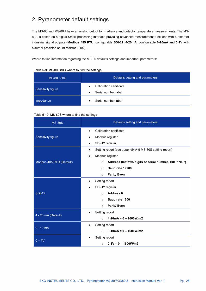
2. Pyranometer default settings
The MS-80 and MS-80U have an analog output for irradiance and detector temperature measurements. The MS-
80S is based on a digital Smart processing interface providing advanced measurement functions with 4 different
industrial signal outputs (Modbus 485 RTU, configurable SDI-12, 4-20mA, configurable 0-10mA and 0-1V with
external precision shunt resistor 100Ω).
Where to find information regarding the MS-80 defaults settings and important parameters:
Table 5-9. MS-80 / 80U where to find the settings
MS-80 / 80U Defaults setting and parameters
Sensitivity figure • Calibration certificate
• Serial number label
Impedance • Serial number label
Table 5-10. MS-80S where to find the settings
MS-80S Defaults setting and parameters
Sensitivity figure
• Calibration certificate
• Modbus register
• SDI-12 register
Modbus 485 RTU (Default)
• Setting report (see appendix A-9 MS-80S setting report)
• Modbus register
o Address (last two digits of serial number, 100 if “00”)
o Baud rate 19200
o Parity Even
SDI-12
• Setting report
• SDI-12 register
o Address 0
o Baud rate 1200
o Parity Even
4 - 20 mA (Default) • Setting report
o 4-20mA = 0 – 1600W/m2
0 - 10 mA • Setting report
o 0-10mA = 0 – 1600W/m2
0 – 1V • Setting report
o 0-1V = 0 – 1600W/m2

EKO INSTRUMENTS CO., LTD. - Pyranometer MS-80/80S/80U - Instruction Manual Ver. 1 Pg. 29
3. Irradiance conversion
For MS-80, MS-80U with analog mV output the global solar Irradiance [W/m2] can be determined by
measuring the output voltage [mV] divided by the individual sensor sensitivity [μV/W・m-2]. The maximum
output voltage can be calculated by multiplying the maximum solar irradiance with the calibration factor [e.g.
when the sensitivity of the MS-80 pyranometer is about 10μV/W・m-2 or 0.010mV/W・m-2, the maximum
output voltage is about 1,400W/m2 times 0.010mV/W・m-2 = 14mV].
Analog output
The solar irradiance in Watts per meter squared [W/m2] is obtained when the output voltage E [μV] is divided
by the sensitivity of the pyranometer S [μV/W・m-2]. This calculation is expressed by the following formula:
I [W/m2] =
*The sensitivity S for the pyranometer is stated on the calibration certificate and the product label.
4-20mA output
If the measurement range can be selected on the data logger, select the measurement range, which can
accurately measure the signal within a range of 4 to 20mA. The output for the MS-80S is set to be 1,600W/m2
at 20mA.
When the solar irradiance current value is A [mA], the solar irradiance I [W/m2] can be determined by the
following formula:
I [W/m2] = (A [mA] - 4) x (1600 / 16)
Note: When the range setting is changed for example 4-20 mA = 0-2000 [W/m2]
I [W/m2] = (A [mA] - 4) x (2000 /16)
0-1V output
If the measurement range can be selected on the data logger, select the measurement range, which can
accurately measure the signal within a range of 0 to 1V. The output for the MS-80S is set to be 1,600W/ m2 at
1V.
When the solar irradiance voltage value is V [V], the solar irradiance I [W/m2] can be determined by the
following formula:
I [W/m2] = V [V] x 1600
MS-80S [Modbus RTU Output, SDI-12 Output]
When using the digital output (Modbus or SDI-12) by default the irradiance conversion is performed on-board
and is one of the measurement parameters within the data string.
E [μV]
S [μV/W・m-2]

EKO INSTRUMENTS CO., LTD. - Pyranometer MS-80/80S/80U - Instruction Manual Ver. 1 Pg. 30
4. Daily radiant energy
The total daily radiant energy in Joule per meter squared [J/m2] is obtained by integrating the solar irradiance over
time. To calculate the total daily radiant energy in Joule per meter square [J/m2], multiply the averaged solar
irradiance I [W/m2] by the averaging interval period [s]. Then sum-up the total data number [n] of averaged data
points in one day.
Its physical unit is expressed with [J/m2] and can be calculated with J = W・S

EKO INSTRUMENTS CO., LTD. - Pyranometer MS-80/80S/80U - Instruction Manual Ver. 1 Pg. 31
6. Maintenance & Troubleshooting
6-1. Maintenance
By using the MS-80 pyranometers accurate results can be obtained if the glass dome and the condition of the
instrument are maintained properly. Furthermore, regular maintenance and scheduled re-calibrations can extend
the lifetime of the pyranometers. However, environmental conditions, such as for instruments mounted near highly
frequented traffic lanes or airports, may have a deteriorating effect on the materials. Therefore, proper maintenance
is needed and has to be adapted to the local environmental conditions.
The following table describes the common maintenance tasks that should be performed on a regular basis:
Table 6-1. Maintenance Items1
※except for MS-80U
Maintenance
Item Frequency How To Effect
Clean Glass
Dome
Several
times per
week
Keep the glass dome clean by using
demineralized water and wiping with a
soft cloth dry and clean.
The irradiance measurement will be
affected due to a change in
transmittance.
Check
Appearance
Condition
Weekly Check for cracks and scratches on the
glass dome and body.
May lead to shade on the detector and
enhanced soiling.
Check
Spirit level Weekly
Verify if the pyranometer is levelled by
checking the bubble is in the center ring
of spirit level. [When the pyranometer is
setup in horizontal position].
An additional cosine/azimuth error will
be introduced.
Check
Cable
Condition
Weekly
Verify if the cable connector is properly
connected, tightened to the instrument,
and how cable is lined; make sure the
cable is not shaking from the wind.
A disconnected cable will cause
sporadic reading errors or failure of
operation. If the cable is damaged, it
may lead to noise or electric shock.
Check
Setup Base
Condition
Weekly
Check if the instrument is tightened
properly to the mounting base plate and
the base plate and/or table is securely
fastened in a proper condition.
Loose instruments and/or mounting
plates can lead to damages of the
instruments and/or injury.
Check the
Sunscreen[*]
Weekly,
Before/Aft
er Bad
Weather
Verify if the sunscreen is securely fixed
on the body, and knurling screw is
securely tightened.
May lead to damaging the instrument
and/or lead to increasing
measurement error due to
temperature increase by sunscreen
coming off.
Recalibration Every 5
Years
To maintain the best possible
measurement accuracy, recalibration of
the pyranometer is recommended.
Contact EKO for more details and
requests for a recalibration and
maintenance service.
Due to natural aging of materials the
detector sensitivity of the pyranometer
can gradually change over time.

EKO INSTRUMENTS CO., LTD. - Pyranometer MS-80/80S/80U - Instruction Manual Ver. 1 Pg. 32
Table 6-2. Maintenance Items2 (Advanced remote check can be done on MS-80S)
Maintenance
Item Frequency How To Effect
Data validity Weekly
Check the daytime irradiance data and
compare to previous days or adjacent
pyranometers.
When large difference occurs
operating problems or installation
issues can be detected.
Presence of
noise Weekly Check night-time irradiance values
Night-time offsets and sensor stability
issues can be revealed.
Abnormal
temperature
detection
Weekly
[MS-80S]
Check the body temperature via
Modbus or SDI-12 output.
If the inside temperature becomes
abnormally high, the life of the product
will be shortened.
Confirm the
effect of
desiccant
Weekly
[MS-80S]
Check the relative humidity via
Modbus or SDI-12 output.
The condition of the drying agent can
slightly change over time. The value
should be below 30%.
Checking the
tilt angle Weekly
[MS-80S]
Check the tilt angle and roll angle via
Modbus or SDI-12 output.
Any change in tilt position after the
installation can affect the
measurements due to the cosine
response of the sensor.

EKO INSTRUMENTS CO., LTD. - Pyranometer MS-80/80S/80U - Instruction Manual Ver. 1 Pg. 33
6-2. Cal ibrat ion and Measurement Uncertainty
It is recommended to recalibrate MS-80/MS-80S/MS-80U once every 5 years in order to verify the good quality of
the solar radiation measurements. In the following paragraph the calibration method of EKO pyranometers and their
calibration uncertainty is explained. For further information about recalibration and maintenance procedures, please
contact EKO or find on the EKO website [http://eko-eu.com].
EKO can offer calibration service for pyranometers and pyrheliometers in-house. Based on the applied calibration
methods EKO provides the best quality solar sensor calibrations compliant to the international standards defined
by ISO/IEC17025 / 9847 [Indoor method] and ISO9059 [Outdoor method] [Certification: L13-94-R2 /
www.pjlabs.com]
1. Calibration Method MS-80 is calibrated indoors according to the ISO 17025 / 9847 international standard against a 1000W/m2 AAA
class solar simulator radiation source and designated calibration facility.
Indoor Calibration Procedure
Both reference and field pyranometers are placed in horizontal position in the center of the light beam at equal
distance to the solar simulator light source. The pyranometers are alternatively exposed to the solar simulator beam
hence the output is measured from each pyranometer for a specified time. From the reference pyranometer output
[mV] and known sensitivity [μV//W/m2] the sensitivity figure [μV/W/m2] of the field pyranometer based on 10 data
samples can be calculated.
Measurement Uncertainty of Indoor Calibration
The calibration uncertainty of MS-80 can be kept below (0.7%) as stated in the scope of accreditation and stated
on each calibration certificate. Calibration in the lab is performed at a constant ambient temperature and ultra stable
light conditions. Hence the repeatability of the method and pyranometers under test can be well maintained. The
pyranometer calibration uncertainty is determined with consideration of uncertainty of the reference pyranometer
and maximum variation of incident light during the measurement of field pyranometer and reference pyranometer.
The expanded calibration uncertainty of each calibrated MS-80 model, and its results are stated on the calibration
certificate.
2. Calibration Traceability The MS-80 reference pyranometer is traceable to the absolute cavity pyrheliometer maintained at EKO. The
absolute cavity pyrheliometer is directly traceable to the WRR [World Radiometric Reference] which is the Primary
Standard Group of Absolute Cavities maintained at PMOD (Davos, Switzerland). The logger system used for the
calibration measurement is traceable to JEMIC [Japan Electric Meters Inspection Cooperation].
Every year the MS-80 reference pyranometer is calibrated against the absolute cavity pyrheliometer, together with
5 other units part of the internal reference group of MS-80 pyranometers according the Shade / unshade Method
[Method for Calibrating Reference and Field Pyranometers (1995)] Bruce W Forgan]. During the IPC the EKO
absolute cavity is calibrated against the WRR every 5 years. Every year the EKO absolute cavity scale is examined
during the NPC at NREL (Boulder, USA).

EKO INSTRUMENTS CO., LTD. - Pyranometer MS-80/80S/80U - Instruction Manual Ver. 1 Pg. 34
6-3. Troubleshoot ing
Read the following in case of any sensor trouble. If any questions should remain, please contact EKO for further
technical support.
Table 6-3. Troubleshooting in field
Failure Action
There is
no output.
MS-80
MS-80U
Make sure that the sensor cable is connected properly to the instrument. To verify the
connection, measure the impedance of output cable [between the “+” and the “-” wires] and
check if the measured impedance is within the proper range as shown in the specification
table.
MS-80S
Make sure that the sensor is properly connected, and type of power supply and voltage values
are appropriate. Also check the communication settings [i.e. port, baudrate, converter ID] are
appropriate.
Output value is too
low
The glass dome maybe soiled with rain or dust. Clean the glass dome with demineralized
water and soft cloth.
The output may decrease over time. Recalibrate periodically.
Negative output
signal
during night-time.
Pyranometers generate an output signal, which is proportional to the temperature differences
between the sensor’s so-called hot and cold junctions. Night-time offset can occur when the
dome temperature will cool down below the temperature of the detector. A slight negative
offset within the specification can be expected.
Unusual noise
Check the shield connection and make sure it is connected securely.
Make sure if the output cable is not shaking from the wind; take necessary measure by fixing
or lining the cables through metal pipe.
Check for any objects, which emit electromagnetic wave around the instrument and or cable.
When using a data logger or a measuring device with <100MΩ input impedance for MS-80
and MS-80U, a data logger potentially does not measure the sensor output correctly; thus
take following measures in composition:
1. Use a measuring device with input impedance more than 100MΩ
2. Set up the integration time and stability time as long as possible.
3. Use moving average processing on the data
4. Attach 2 or more ferrite cores at the end of the cable.
5. Avoid ground loops. Electrically isolate the pyranometer from the mounting platform.
6. Connect the shield of the cable to the data logger analog ground.
7. Use a data logger with differential voltage input.
4-20mA and 0-1V
output outside range
Example) 2mA output
when using 4-20mA.
The fluctuation of
measured current is
large.
If it is confirmed that the wiring is correct, connect the ground wire of this product to the
negative side of the data logger voltage (current) measurement terminal.
Note that the appropriate ground wire connection method for this product may differ
depending on the type of data logger and measurement environment. Select an appropriate
ground wire connection method for this product according to the type of data logger and
measurement environment.
EKO INSTRUMENTS CO., LTD. - Pyranometer MS-80/80S/80U - Instruction Manual Ver. 1 Pg. 35
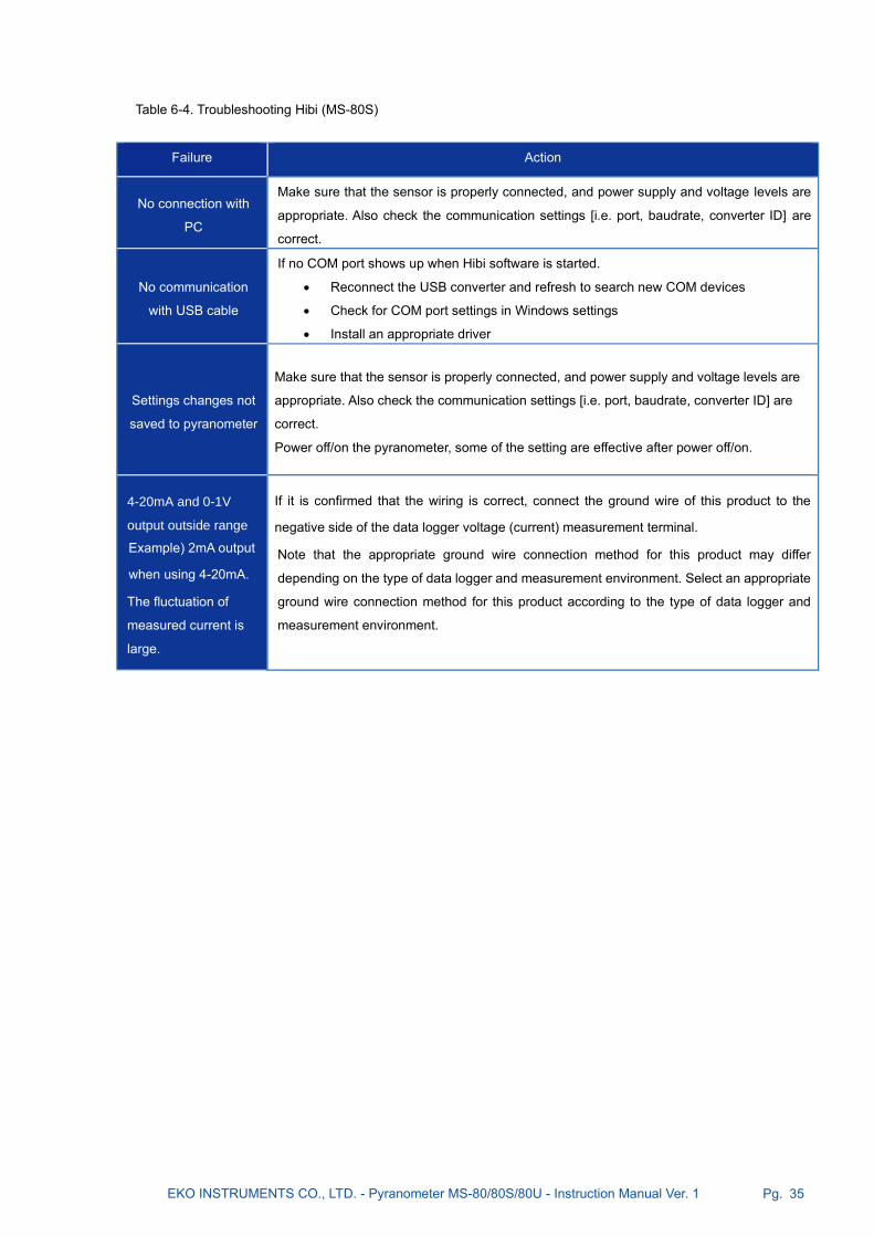
Table 6-4. Troubleshooting Hibi (MS-80S)
Failure Action
No connection with
PC
Make sure that the sensor is properly connected, and power supply and voltage levels are
appropriate. Also check the communication settings [i.e. port, baudrate, converter ID] are
correct.
No communication
with USB cable
If no COM port shows up when Hibi software is started.
• Reconnect the USB converter and refresh to search new COM devices
• Check for COM port settings in Windows settings
• Install an appropriate driver
Settings changes not
saved to pyranometer
Make sure that the sensor is properly connected, and power supply and voltage levels are
appropriate. Also check the communication settings [i.e. port, baudrate, converter ID] are
correct.
Power off/on the pyranometer, some of the setting are effective after power off/on.
4-20mA and 0-1V
output outside range
Example) 2mA output
when using 4-20mA.
The fluctuation of
measured current is
large.
If it is confirmed that the wiring is correct, connect the ground wire of this product to the
negative side of the data logger voltage (current) measurement terminal.
Note that the appropriate ground wire connection method for this product may differ
depending on the type of data logger and measurement environment. Select an appropriate
ground wire connection method for this product according to the type of data logger and
measurement environment.

EKO INSTRUMENTS CO., LTD. - Pyranometer MS-80/80S/80U - Instruction Manual Ver. 1 Pg. 36
7. Specifications
7-1. Speci f icat ions
1. Pyranometer Specifications The comparison table below, Table 7-1, shows typical values for the characteristic parameters of the EKO
Pyranometers and the corresponding values of the ISO 9060: 2018 standard. The content of the characteristic item
is partly changed from ISO 9060: 1990. Please also refer to "A-2. Pyranometer Characteristics List".
Table 7-1. Pyranometer specifications
Characteristics
MS-80 / MS-80U MS-80S
ISO9060: 2018 Class A
[ISO9060: 1990] [Secondary Standard]
Spectrally flat Compliant Compliant
Fast response Compliant Compliant
Response time
95% output <10 Sec <0.5 Sec <0.5 Sec
Response time
99% output --- <1 Sec <1 Sec
Zero off-set (a)
-200W/m2 ±7 W/m2 ±1 W/m2 ±1 W/m2
Zero off-set (b)
5K/hr ±2 W/m2 ±1 W/m2 ±1 W/m2
Total zero off-set (c) ±10 W/m2 ±2 W/m2 ±2 W/m2
Non-stability ±0.8 %/1yr ±0.5 %/5yrs ±0.5%/5yrs
Nonlinearity ±0.5 % ±0.2 % ±0.2 %
Directional response ±10 W/m2 ±10 W/m2 ±10 W/m2
Spectral error ±0.5% ±0.2% ±0.2%
Spectral selectivity ±3 % ±3 % ±3 %
Temperature response
-10 to +40 ±1 % ±1 % ±0.5 %
Temperature response
-20 to +50 --- ±1 % ±0.5 %
Tilt response ±0.5 % ±0.2 % ±0.2 %
Additional signal
processing error ±2 W/m2 --- ±1 W/m2

EKO INSTRUMENTS CO., LTD. - Pyranometer MS-80/80S/80U - Instruction Manual Ver. 1 Pg. 37
Table 7-2. Other Specification
Characteristics MS-80 MS-80S MS-80U
Field of View 2π [sr]
Wavelength range 285 to 3,000nm
[1] Operating temperature -40 to +80
[2] Maximuml Irradiance 4,000W/m2
Spirit level accuracy 0.1 °
Tilt sensor accuracy --- ±1° ---
Humidity sensor accuracy --- Nominal: ±2%RH ---
Temperature sensor of PCB
(tolerance) --- ±0.5 ---
Detector temperature sensor
Till S/N S19046150
NTC10kΩ
From S19046151
Pt100 Class A [3]
±0.5%
Pt100 Class A [4]
±0.1% 10kΩ NTC
Internal temperature sensor --- ±0.5 ---
Environmental Protection [IP
Code] IP67 Equivalent [IEC60529]
Weight 0.35kg 0.41kg 0.21 kg
Body Anodized
Sensitivity Approx.10μV/W・m-2
Approx.10μV/W・m-2
[4-20mA : 0-1600W・m-2] [5]
[0-1V : 0-1600W・m-2] [5]
Approx.10μV/W・m-2
Impedance Approx. 45kΩ --- Approx. 45kΩ
Output Cable
[Outer diameter]
AWG22
0.3mm2 x 5 pins [φ5.9mm]
AWG28
0.1mm2 x 4 pins [φ3.3mm]
Output Cable Terminal Pin-Terminal [0.3-9.5] Solder
Output [or Signal] Voltage [mV]
Modbus 485 RTU (default),
configurable SDI-12,
4-20mA(default) [5] [6],
configurable 0-10mA / 0-1V
[5] [6] with external 100Ω
precision shunt resistor
Voltage [mV]
Resolution --- < 0.01W・m-2 [4] ---
Input Power Supply ---
Modbus: DC5V±5%
or DC8V to DC30V±10%
0-1V/4-20mA: DC8V to
30V±10%
SDI-12: DC9.6V to 16V
---
EKO INSTRUMENTS CO., LTD. - Pyranometer MS-80/80S/80U - Instruction Manual Ver. 1 Pg. 38
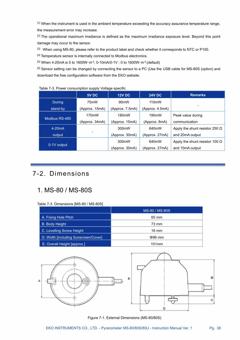
[1] When the instrument is used in the ambient temperature exceeding the accuracy assurance temperature range,
the measurement error may increase.
[2] The operational maximum irradiance is defined as the maximum irradiance exposure level. Beyond this point
damage may occur to the sensor.
[3] When using MS-80, please refer to the product label and check whether it corresponds to NTC or P100.
[4] Temperature sensor is internally connected to Modbus electronics.
[5] When 4-20mA is 0 to 1600W・m-2, 0-10mA/0-1V : 0 to 1600W・m-2.(default)
[6] Sensor setting can be changed by connecting the sensor to a PC (Use the USB cable for MS-80S (option) and
download the free configuration software from the EKO website.
Table 7-3. Power consumption supply Voltage specific
5V DC 12V DC 24V DC Remarks
During
stand-by
75mW
(Approx. 15mA)
90mW
(Approx. 7.5mA)
110mW
(Approx. 4.5mA) -
Modbus RS-485 170mW
(Approx. 34mA)
180mW
(Approx. 15mA)
190mW
(Approx. 8mA)
Peak value during
communication
4-20mA
output -
300mW
(Approx. 30mA)
640mW
(Approx. 27mA)
Apply the shunt resistor 250 Ω
and 20mA output
0-1V output 300mW
(Approx. 30mA)
640mW
(Approx. 27mA)
Apply the shunt resistor 100 Ω
and 10mA output
7-2. Dimensions
1. MS-80 / MS-80S
Table 7-3. Dimensions [MS-80 / MS-80S]
MS-80 / MS-80S
A. Fixing Hole Pitch 65 mm
B. Body Height 73 mm
C. Levelling Screw Height 16 mm
D. Width [including Sunscreen/Cover] Φ96 mm
E. Overall Height [approx.] 101mm
Figure 7-1. External Dimensions (MS-80/80S)

EKO INSTRUMENTS CO., LTD. - Pyranometer MS-80/80S/80U - Instruction Manual Ver. 1 Pg. 39
2. MS-80U
Table 7-4. Dimensions [MS-80U]
MS-80U
A. Fixing Hole Pitch 65 mm
B. Body Height 50 mm
C. Levelling Screw Height 16 mm
D. Width Φ78 mm
Figure 7-2. Outer Dimensions [MS-80U]

EKO INSTRUMENTS CO., LTD. - Pyranometer MS-80/80S/80U - Instruction Manual Ver. 1 Pg. 40
7-3. Output Cables
See [5-2. Setup, 2. Wiring] for instruction
1. MS-80 / MS-80S
Different lengtsh (10m standard, 20m / 30m / 40m / 50m optional).
2. EKO Converter Cable (Option)
3. MS-80U
No. Line color
1. Brown
2. White
3. Blue
4. Black
5. Gray
Shield
Figure 7-3. Output Cables [MS-80 / MS-80S]
No. Line color
1. Red
2. White
3. Green
4. Black
Shield
Figure 7-5. Output Cables [MS-80U]
Figure 7-4. EKO Converter cable [MS-80S]
USB Type-A

EKO INSTRUMENTS CO., LTD. - Pyranometer MS-80/80S/80U - Instruction Manual Ver. 1 Pg. 41
7-4. Accessories L ist
Table 7-5. Accessories List
Option Items Description Pyranometers
Output cable Cable Length: 10m, 20m, 30m, 50m
Terminals: Fork Terminals, Round Terminals, Pin Terminals
MS-80 / 80S
Ventilation Unit with
Heater MV-01 ventilator and heater
MS-80 / 80S
EKO Converter Cable
Converts from RS485 → USB for the communication with
MS-80S and allows to connect to PC via USB terminal.
Cable Length:1.8m
MS-80S

EKO INSTRUMENTS CO., LTD. - Pyranometer MS-80/80S/80U - Instruction Manual Ver. 1 Pg. 42
APPENDIX
A-1. Radiometr ic Terms
Table A-1. Definitions of Terms
Hemispheric Solar Irradiance Cosine-weighted solar irradiance received over a solid angle of 2πsr on a
plane surface, expressed in units of W/m2 or kW/m2.
Global Solar Irradiance, Global
Horizontal Irradiance [GHI]
Hemispherical solar irradiance received on a horizontal plane surface,
expressed in units of W/m2 or kW/m2.
Direct Solar Irradiance, Direct Normal
Irradiance [DNI]
Normal-incidence solar irradiance received over a small solid angle which
includes the circumsolar irradiance, expressed in units of W/m2 or kW/m2.
Diffuse Solar Irradiance, Diffuse
Horizontal Irradiance [DHI]
Hemispherical solar irradiance without the direct solar irradiance, i.e.
indirect irradiance of the scattered solar radiation [by air molecules, aerosol
particles, clouds, etc.], expressed in units of W/m2 or kW/m2.
Pyranometer A radiometer designed to measure the hemispheric solar irradiance over
the wavelength range of about 300 to 3,000nm.
Pyrheliometer A radiometer designed to measure the direct solar irradiance over a certain
solid angle including the circumsolar irradiance.
World Meteorological Organization
(WMO)
It is a specialized organization of the International Union that carries out
international standardization and coordination of meteorological work.
WMO: Abbreviation for World Meteorological Organization
World Radiation Reference
[WRR]
Radiometric reference instrument system which has an uncertainty of less
than +/-0.3%, expressed in SI units.
This reference is maintained by the World Meteorological Organization
[WMO], and it has been issued since January 1, 1980
ISO9060
An ISO norm [International Standard]. The first edition was published in
1990, then the second edition was revised in 2018.
Based on the performance of each characteristic, Pyranometer is classified
into three classes A, B, and C, and specifications of "Spectrally flat
radiometer" and "Fast response radiometer" are set as sub-categories.
Pyrheliometer is classified into 4 classes of AA, A, B and C based on the
performance of each characteristic, and specifications of "spectrally flat
radiometer" and "Fast response radiometer" are set as sub-categories.

EKO INSTRUMENTS CO., LTD. - Pyranometer MS-80/80S/80U - Instruction Manual Ver. 1 Pg. 43
A-2. Pyranometer Character is t ics
Table A-2. Pyranometer Characteristics [see also ISO-9060:2018, CIMO Guide, WMO No. 8, 2008]
Response Time
The time [seconds] of a pyranometer sensor to reach 95% of its final output signal.
[ISO 9060: 2018 added] If the response time reach to 95% is less than 0.5 seconds, "fast
response" is attached to the applicable class as a subcategory.
Zero Off-Set a Response [dark-signal] to 200W/m2 net thermal radiation [ventilated]
Zero Off-Set b Response [dark-signal] to 5K per hour change in ambient temperature
Total Off-set c [ISO 9060: 2018 added] Total zero off-set including the effects a], b] and other sources
Non-Stability Rate of change [%] of the pyranometer sensitivity per year.
Nonlinearity Percentage deviation from the responsivity at 500W/m2 due to any change of irradiance
within the range 100W/m2 to 1000W/m2.
Directional Response
Also referred to as cosine error [W/m2]; the range of errors caused by assuming that the
normal incidence responsivity is valid for all directions when measuring, from any direction,
a beam radiation whose normal incidence irradiance is 1000W/m2
[ISO 9060: 2018 modified] Include the zenith angle of zenith angle 90 ° or more.
Spectral error
[ISO 9060: 2018 added] Maximum spectral mismatch error of Pyranometer [%] with respect
to spectral irradiance at AM 1.5 and AM 5 under multiple atmospheric conditions on fine
weather against the reference standard spectral irradiance defined by IEC60904-3: 2016
Photovoltaic devices - ”Measurement principles for terrestrial photovoltaic [PV] solar devices
with reference spectral irradiance data.”
Spectral selectivity Percentage deviation of the product of spectral absorptance and spectral transmittance from
the corresponding mean within the range 0.35μm to1.5μm.
Spectrally flat
Pyranometer
[ISO 9060: 2018 added] If the spectral selectivity is less than 3 %, "spectrally flat" is attached
to the applicable class as a subcategory.
Temperature Response [ISO 9060: 2018 modified] Percentage maximum output error due to any change of ambient
temperature between -10 to 40 against the output at 20.
Tilt Response [ISO 9060: 2018 modified] Percentage deviation from the responsivity at 0 tilt [horizontal]
due to change in tilt from 0 to 180 at 1000W/m2.
Additional processing
errors
[ISO 9060: 2018 added] Error generated when converting the analog output of Pyranometer
or Pyrheliometer into a digital signal with a signal converter etc.

EKO INSTRUMENTS CO., LTD. - Pyranometer MS-80/80S/80U - Instruction Manual Ver. 1 Pg. 44
A-3. Software (Hibi )
‘Hibi’ means ‘day by day’ in Japanese, and with this program, users will be able to visualise detection signals, set
communication parameters, and rapidly troubleshoot any issues from day one. You can change the settings of the
MS-80S using the Windows software downloadable from the EKO website (MS-80S product page) and the optional
USB cable.
1. Software Installation Follow the steps below to install “Hibi” configurator software.
1) Download the latest version of the "hibi.zip" file [Compressed file: Zip format] from MS-80S product page
on the EKO website.
2) Unzip “hibi.zip” file and check that the “setup.exe” file exists.
3) Run the “setup.exe” file to install “Hibi” configurator software.
2. Hardware Preparation After the software is installed, connect the MS-80S with a PC to change the setting..
1) After installing the software, connect the USB connector of "RS485/USB Converter cable" to the PC.
2) Connect the ends of the signal cable of MS-80S to the communication terminal of "RS485/USB converter".
3) Connect the power lines of the signal cable to the power supply (DC5V or 8 to 30V), and turn on the power
supply. (Refer to Figure A3-1.)
If you use the optional “EKO Converter cable”, you can install it simply by inserting the cable connector
into the main unit. Power for the MS-80S can be supplied via USB. (See Figure A3-2).
* This conversion cable is for installation, so please avoid using it outdoors for a long time. Because the
ground wire is not connected, surges can damage your PC during a lightning strike.
RS485/USB converter
Power Supply
DC5V, or 8~30V
+
-
+ -
(Terminal block)
MS-80S cable: Blue (+ / A) RS485/USB Converter terminal: (+)
MS-80S cable: black (- / B) RS485/USB Converter terminal: (-)
* Connect the power supply GND and RS485GND
PC
Figure A3-1. Hardware preparation
Connect the cable to MS-80S
PC
Figure A3-2. Using “EKO Converter cable”

EKO INSTRUMENTS CO., LTD. - Pyranometer MS-80/80S/80U - Instruction Manual Ver. 1 Pg. 45
3. Software Start the “Hibi” software and make the required settings.
1) Start “Hibi” software. (Launch the software from “EKOApp1.exe” located in the shortcuts or installation
folder.
2) After the software starts, the "Welcome" window appears.
3) Automatic connection
When using the “Auto-connect” function to connect MS-80S with the “Hibi” software, select the COM port
that the RS485/USB converter cable is connected to.
Click “Select” of “COM port:” on the startup screen, and select the COM port number assigned
to the RS485 / USB conversion cable from the displayed COM port numbers.
If you can't find a selectable COM port, click the Refresh button and click Select again to try again.
Figure A3-3. Welcome window
Figure A3-4. Com port select

EKO INSTRUMENTS CO., LTD. - Pyranometer MS-80/80S/80U - Instruction Manual Ver. 1 Pg. 46
Check that the power supply of the main unit is “OFF”. Then, click "CONNECT" button.
Power on the MS-80S within 10 seconds once the "Connecting your sensor" message appears.
When the connection is completed, the window automatically switches to the "Dashboard" window. In the
upper-right corner of the display changes to "Pyranometer Connected".
Figure A3-5. Com port select
Refresh
button
Figure A3-6. Connecting screen
Figure A3-7. Dashboard

EKO INSTRUMENTS CO., LTD. - Pyranometer MS-80/80S/80U - Instruction Manual Ver. 1 Pg. 47
If the connection fails, the screen returns to the "Welcome" screen and "CONNECTION FAILED" is
displayed.
Make sure the connection settings are correct. To perform the ”Auto-connection” again, turn off the power of
the MS-80S, select "COM port", and then click "CONNECT".
For manual connections, click “View settings” at the bottom of “CONNECTION FAILED” to go to “Settings
screen”. (As for how to set and connect by “Manual connection”, refer to the procedures (4) Manual
connection) from the next section.
4) Manual connection
After turning on the power of the MS-80S, click "CONNECT" without selecting "COM port".
Clicking "view settings" at the bottom of the "CONNECTION FAILED" screen moves to the "Settings" screen.
(The same screen appears even when the “ Auto-connection” fails. To perform manual connection, set and
connect using this procedure.)
After that, click the “CONNECT” button in Connection status.
When the connection is completed, "Connected" is displayed.
"Sensor Pyranometer Connected" is also shown in the upper-right corner of the display.
Figure A3-8. CONNECTION FAILED
Figure A3-9. Manual connection

EKO INSTRUMENTS CO., LTD. - Pyranometer MS-80/80S/80U - Instruction Manual Ver. 1 Pg. 48
When the connection fails, the "Oops..." screen is displayed with the cause of the connection failure.
When connection fail appears
Check that the cable connection, COM port and the
communication requirements are correct.
When changing the connection condition after
successful connection, set "COM port", "Baud rate"
and "Parity" in the "Serial communication" setting of
the "COMMUNICATION" items and set "Modbus
address [1-247]" and "Register Type" in the
"Addresses" setting.
After entering the settings, click “APPLY CHANGES”
A confirmation window will be displayed.
Click “YES, SAVE” to make the settings for the MS-
80S.
The settings in "Settings" can be saved / read /
exported to CSV files.
Click the button with icons in the upper-right corner of
“Settings” window.
・ "Save" button: Save the settings.
・ “Read” button: Read out the settings.
・ “Output” button: Output the settings to CSV file
Figure A3-12. Apply changes screen
Figure A3-11. Oops screen
Figure A3-10. Disconnect appear

EKO INSTRUMENTS CO., LTD. - Pyranometer MS-80/80S/80U - Instruction Manual Ver. 1 Pg. 49
5) Setting items
1. COMMUNICATION setting items
Item Name Setting contents Setting range
Mode Modbus Switch to Modbus 485 RTU interface (Default)
SDI-12 Switch to SDI-12 interface.
Serial
communication
Auto search OFF/ON: Manual/Auto-connect
COM Port COM1 to COM256
Baud rate 2400 / 4800 / 9600 /19200 / 38400 / 115200bps
Parity Even / Odd / None
Addresses
Modbus address [1-
247]
1 to 247 (last 2 digits of serial number is default
address, 100 when “00”)
Register Type S-series/ M-series/ SMP-series/ SRD-series
SDI-12 address 0 to 9 / A to Z / a to z
Connection status --- Connected / Disconnect
Figure A3-13. Settings screen
“Output” button
“Read” button
"Save" button
Figure A3-14. Communication setting screen

EKO INSTRUMENTS CO., LTD. - Pyranometer MS-80/80S/80U - Instruction Manual Ver. 1 Pg. 50
2. "SENSOR INFORMATION" setting items
Item Name Setting contents Setting range
Model
information
Model Model name registered in the MS-80S (cannot be
changed)
Serial number Serial number registered to the MS-80S (cannot be
changed)
MFG. date Date of manufacturing (cannot be changed )
Firmware version Firmware version of MS-80S (cannot be changed)
Hardware version Hardware version of MS-80S (cannot be changed)
Calibration
Calibration date Calibration date and time: Registered at the time of
calibration by the manufacturer, but can also be
registered by the user.
Sensitivity
[µV/W/m2]
Sensitivity constant: Registered at the time of
manufacturer calibration, but can also be registered at
the user side.
3. "OUTPUT" setting items
Item Name Setting contents Setting range
Analog
output
Enable analog
output
Analog output OFF/ON (selected with the radio
button)
Either 4-20mA or 0-1V power can be selected.
* Default is 4-20mA.
4-20mA Current(mA)/Irradiance(W/m2): Setting of minimum
and maximum irradiance (W/m2) corresponding to the
output.
0-1V Voltage(V)/Irradiance(W/m2): Setting of minimum and
maximum irradiance (W/m2) corresponding to the
output.
Resistance (ohm) Load resistor value for calculating output current at 0-
1V output
Figure A3-15. Sensor information settings

EKO INSTRUMENTS CO., LTD. - Pyranometer MS-80/80S/80U - Instruction Manual Ver. 1 Pg. 51
4. "TEMPERATURE" setting items
Item Name Setting contents Setting range
UNIT Preferred unit
(temperature unit setting)
-Celsius / -Fahrenheit / K-Kelvin
Figure A3-16. Analog settings screen
Figure A3-17. Sensor settings screen

EKO INSTRUMENTS CO., LTD. - Pyranometer MS-80/80S/80U - Instruction Manual Ver. 1 Pg. 52
5. "SENSOR POSITION" setting items
The sensor position can be measured in two different planes (X, Y).
<Tilt (X axis)> (90º to 0) and (0 to -90º)
<Roll (Y axis)> (90º to 0) and (0 to -90º)
The tilt and roll angles are relative to the calibrated X and Y axis of the sensor and surface mounting
plane X’ and Y’. When the sensor is positioned in the same plane X = X’ and Y = Y’, the measured
angles X and Y represent the corresponding plane of installation X’ and Y’.
Clicking "ZERO ADJUSTMENT" allows you to adjust Tilt (X axis) and Roll (Y axis) of Tilting
items using the present tilt angle as 0°. The spirit vial can be used as a reference to readjust
the tilt and roll position. The MS-80S X and Y position is factory calibrated.
Figure A3-18. Sensor Position setting
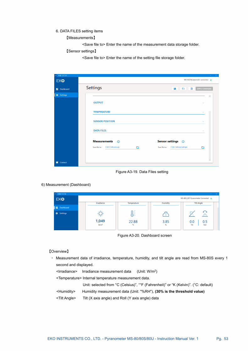
EKO INSTRUMENTS CO., LTD. - Pyranometer MS-80/80S/80U - Instruction Manual Ver. 1 Pg. 53
6. DATA FILES setting items
【Measurements】
<Save file to> Enter the name of the measurement data storage folder.
【Sensor settings】
<Save file to> Enter the name of the setting file storage folder.
6) Measurement (Dashboard)
【Overview】
・ Measurement data of irradiance, temperature, humidity, and tilt angle are read from MS-80S every 1
second and displayed.
<Irradiance> Irradiance measurement data (Unit: W/m2)
<Temperature> Internal temperature measurement data.
Unit: selected from °C (Celsius)”, “°F (Fahrenheit)” or “K (Kelvin)”. (°C: default)
<Humidity> Humidity measurement data (Unit: "%RH"), (30% is the threshold value)
<Tilt Angle> Tilt (X axis angle) and Roll (Y axis angle) data
Figure A3-19. Data Files setting
Figure A3-20. Dashboard screen

EKO INSTRUMENTS CO., LTD. - Pyranometer MS-80/80S/80U - Instruction Manual Ver. 1 Pg. 54
【Real-time measurement view】
<Real time measurement-Irradiance>
- Display measured irradiance data in a graph (1-second update).
- Drag the graph to change the horizontal axis position and use the mouse wheel to zoom in
or out on the desired area.
- The time range of the graph is 00:00:00 to 23:59:59.
- Clicking “Back to default” resets the change of the setting of the graph.
<Data Logging>
Logging function of measurement data
“Sample time:” Set the logging interval for measurement data.
Setting range: 00:01~01:00 (1 sec to 1 min)
“Average interval:” Set the logging interval for averaged measurement data.
Setting range: 00:01~01:00 (1 sec to 1 min)
“Measure intervals:” Set the time interval for data logging.
By checking "Continue next days", it is also possible to keep setting
after the next consecutive days.
“Start at:” Set the start time for data logging.
“Ends at:” Set the end time for data logging.
※ Setting across the day is not possible. The start time must be
earlier than the end time. (Start time < End time)
“LOG DATA buttons:” Click to start logging measurement data.
When "STOP" is clicked while measurement data is being logged,
logging stops.
Figure A3-21. Real-time measurement view
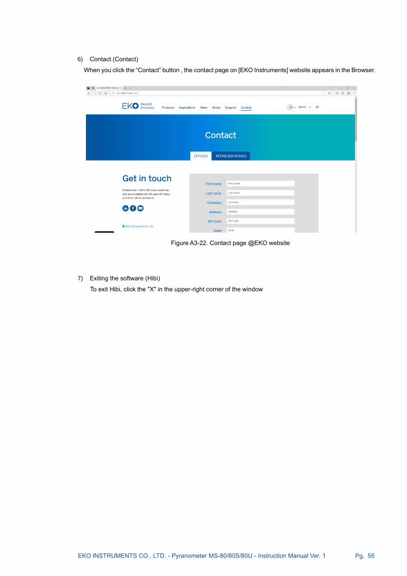
EKO INSTRUMENTS CO., LTD. - Pyranometer MS-80/80S/80U - Instruction Manual Ver. 1 Pg. 55
6) Contact (Contact)
When you click the “Contact” button , the contact page on [EKO Instruments] website appears in the Browser.
7) Exiting the software (Hibi)
To exit Hibi, click the "X" in the upper-right corner of the window
Figure A3-22. Contact page @EKO website

EKO INSTRUMENTS CO., LTD. - Pyranometer MS-80/80S/80U - Instruction Manual Ver. 1 Pg. 56
A-4. Communicat ion Speci f icat ions (Modbus RTU)
A4-1. Outlines
・ This device is compatible with Modbus RTU*. ASCII modes are not supported.
(* This is an open protocol for serial communication developed by Modicon.)
・ The initial setting of the communication interface is Modbus mode. To use the SDI-12 mode, change the
settings from “Hibi” software. After changing the setting, turn the power off and then on again to operate
with SDI-12. To return to Modbus mode again, change the setting from “Hibi” software.
・ It corresponds to RS485, half-duplex and double-wire multi-drop networks.
The communication specifications are as follows.
Table A4-1. Modbus communication protocol
Optional item Remarks
Electrical specifications EIA-485
Connection form Multi-drop method (1 for Master, 31 for Slave, 32 for total)
Communications protocols Modbus RTU ※1 (Slave)
Communication speed baudrate 2400、4800、9600、19200、38400、115200 bps
Data length 8 Bit
Stop bit 1 bit/2 bit ※2
Parity bit None/Odd/Even
Communication distance Max.1000m (ideal value)
Error detecting system CRC-16
※1: An open protocol developed by Modicon for serial communication.
※2: The value of the stop bit is determined automatically by the parity bit setting.
A4-2. Function code
・ There is no distinction between Coil and Discrete Input addresses.
・ There is no distinction between Holding Register and Input Register addresses.
・ Coil, Discrete Input, Holding Register, Input Register addresses start from “0”.
Table A4-2. Supported Function Codes
Function code (hexadecimal) Function
0x01 Read Coils
0x02 Read Discrete Inputs
0x03 Read Holding Registers
0x04 Read Input Register
0x05 Write Single Coil
0x06 Write Single Register
0x10 Write Multiple Registers

EKO INSTRUMENTS CO., LTD. - Pyranometer MS-80/80S/80U - Instruction Manual Ver. 1 Pg. 57
A4-3. Communication specification
・ The address range can be used from 1 to 247.
・ The maximum frame size that can be communicated at a time is 256 bytes (maximum read registers: 125,
maximum write registers: 123).
・ The baud rate (bit/sec) can be selected from 2400, 4800, 9600, 19200, 38400 and 115200.
・ Parity can be selected from “Even”, “Odd” or “None”.
・ The bit width is 8 bits, the stop bit is 1 bit when parity is present, and 2 bits when parity is absent.
・ If the address and communication settings are changed, the equipment must be restarted.
Table A4-3. Communication setting
Setting No. Bit rate Parity
0 2400 None
1 2400 Even
2 2400 Odd
3 4800 None
4 4800 Even
5 4800 Odd
6 9600 None
7 9600 Even
8 9600 Odd
9 19200 None
10 (default) 19200 Even
11 19200 Odd
12 38400 None
13 38400 Even
14 38400 Odd
15 115200 None
16 115200 Even
17 115200 Odd
A4-4. Cable connection
・ RS485 communication ground and the power ground are the same.
Be sure to connect the ground of RS485 communication interface to the power ground.
A4-5. Data format
Table A4-4. Data format to use
Format Abstract
U16 Unsigned 16bit Integer
S16 Signed 16bit Integer
U32 Unsigned 32bit Integer
S32 Signed 32bit Integer
F32 IEEE754 32bit floating point format
Str ASCII characters string

EKO INSTRUMENTS CO., LTD. - Pyranometer MS-80/80S/80U - Instruction Manual Ver. 1 Pg. 58
・ The byte order for communication is big endian.
2byte values are sent in the order of H byte → L byte
4byte values are sent in the order of H word → L word
Character strings are sent in the order of 1 byte from the beginning.
Allocation of each format is shown in the table below.
Table A4-5. Assignment of 8/16/32 bit value
8bit 0x12 0x34 0x56 0x78
16bit 0x1234(MSW) 0x5678(LSW)
32bit 0x12345678
Table A4-6. Assignment of 8/16 bits and F32
8bit 0x41 0x45 0x85 0x1E
16bit 0x4145(MSW) 0x851E(LSW)
F32 12.345
Table A4-7. Assignment of 8/16bit and Str
8bit 0x41 0x42 0x43 0x44
16bit 0x4142(MSW) 0x4344(LSW)
Str 'ABCD'
・ The 32-bit register is in the order of high word (MSW) followed by low word (LSW).
The following table shows the cases where 0x12345678 is assigned to address n of Modbus register.
Table A4-8. Relationship between 32-bit values and Modbus registers
32-bit value 0x12345678
Modbus register (address n) 0x1234(MSW)
Modbus register (n+1) 0x5678(LSW)
A4-6. Outline of 1 Holding/Input register map
・ The register map of the Switch starts from address 0.
・ The contents of registers No. 0 to 49 are switched according to the register type setting (No.103).
・ Registers No. 0 to 99 are read-only.
・ Registers after No.100 can be read and written.

EKO INSTRUMENTS CO., LTD. - Pyranometer MS-80/80S/80U - Instruction Manual Ver. 1 Pg. 59
A4-7. No. 0-49 Register details
・ The register map changes depending on the register type setting. The following table shows 4 register
maps.
・ See in parentheses for the unit.
・ Fixed value if the content is numeric.
・ The blank space is not used. It is filled with zero in U16 format.
・ The abbreviations are as follows.
Addr: Modbus slave address (1-247)
Comp Irr: Irradiance value after compensation of temperature and linearity.
Raw.Irr: Irradiance before correction
Temp: Sensor temperature
AD: Input voltage
Sensitivity: Calibration factor
Cal. Date: Calibration date
Supply: Supply Voltage
Sensor Name: Sensor name (MS-80S)
Firm Ver: Firmware version number
Hard Ver: Hardware version number
T. Coeff: Temperature compensation factor, set by No.174-181
L. Coeff: Linearity compensation factor, set by No.182-189

EKO INSTRUMENTS CO., LTD. - Pyranometer MS-80/80S/80U - Instruction Manual Ver. 1 Pg. 60
Table A4-9. No. 0-49 Register S-series type (default)
0 Model U16 Model number of the transmitter. (0x0110)
1 0 U16 Fixed value
2 Comp.Irr F32
Adjusted solar radiation intensity
Unit: W/m2 3
4 to 7 are Reserve
8 Pt100 F32
Sensor temperature
Unit: ( °C / / K) 9
10 to 13 are Reserve
14 X-axis tilt angle
(degree) F32
X-axis component of the tilt angle
Unit: ° 15
16 Y-axis tilt angle
(degree) F32
Y-axis component of the tilt angle
Unit: ° 17
18 Raw.Irr F32
Intensity of solar radiation before correction
Unit: W/m2 19
20 ADmV F32
Sensor output voltage
Unit: mV 21
22 Internal temperature F32
Temperature measured by the internal temperature sensor
Unit: ( °C / / K) 23
24 Internal humidity F32
Relative humidity measured by the internal humidity sensor
Unit: RH % 25
26 to 49 are Reserve
Table A4-10. No.0-49 register M-series type
0
Serial number U16
Serial No. 1st /2nd ASCII
1 Serial No. 3rd/4th ASCII
2 Serial No. 5th/6th ASCII
3 Serial No. 7th/8th ASCII
4 Serial No. 9th/10th ASCII
5 Serial No. 11st/12nd ASCII
6 Serial No. 13rd/14th ASCII
7 Serial No. 15th/16th ASCII
8
"0000000000" U16
"00" (fixed)
9 "00" (fixed)
10 "00" (fixed)
11 "00" (fixed)
12 "00" (fixed)
13 0 U16 Minimum solar radiation intensity 0 (fixed)
14 1600 U16 Maximum solar radiation intensity 1600 (default)
15 2 U16 Measurement Mode (default)
16 Sensitivity
(µV/W/m2) F32
Sensitivity (LSW)
17 Sensitivity (MSW)
18 1 U16 Temperature unit, unit: °C (default)

EKO INSTRUMENTS CO., LTD. - Pyranometer MS-80/80S/80U - Instruction Manual Ver. 1 Pg. 61
19 AD(mV) F32
Input Voltage (LSW)
20 Input voltage (MSW)
21 Comp.Irr(W/m2)
F32
Corrected insolation intensity (LSW)
22 Corrected insolation intensity (MSW)
23 Temp.() F32
Temperature (LSW)
24 Temperature (MSW)
25 8355 U16 Password (fixed)
26 T.Coeff. a F32
Temperature compensation factor 1-a (LSW)
27 Temperature compensation coefficient 1-a (MSW)
28 T.Coeff. b F32
Temperature compensation coefficient 2-b (LSW)
29 Temperature compensation factor 2-b (MSW)
30 T.Coeff. c F32
Temperature compensation factor 3-c (LSW)
31 Temperature compensation factor 3-c (MSW)
32 T.Coeff. d F32
Temperature compensation factor 4-d (LSW)
33 Temperature compensation coefficient 4-d (MSW)
34 L.Coeff. k1 F32
Linearity correction factor 1-k1 (LSW)
35 Linearity correction factor 1-k1 (MSW)
36 L.Coeff. k2 F32
Linearity correction factor 2-k2 (LSW)
37 Linearity correction factor 2-k2 (MSW)
38 L.Coeff. k3 F32
Linearity correction factor 3-k3 (LSW)
39 Linearity correction factor 3-k3 (MSW)
40 L.Coeff. k4 F32
Linearity correction factor 4-k4 (LSW)
41 Linearity correction factor 4-k4 (MSW)
42 Addr U16 Node number
43 BPS U32
Communication speed (LSW)
44 Communication speed (MSW)
45 Parity U16 Parity bit
46 to 49 are Reserve

EKO INSTRUMENTS CO., LTD. - Pyranometer MS-80/80S/80U - Instruction Manual Ver. 1 Pg. 62
Table A4-11. No. 0-49 register SMP-series type
0 65535 U16 Fixed value
1 100 U16 Fixed value
2 1 U16 Fixed value
3 0 U16 Fixed value
4 1 S16 Fixed value
5 Comp.Irr (W/m2) S16
6 Raw.Irr (W/m2) S16
7 0 S16 Fixed value
8 Temp. (0.1) S16
9 Supply (0.1V) S16
10 0 S16 Fixed value
11 0 S16 Fixed value
12 0 S16 Fixed value
13 0 S16 Fixed value
14 0 S16 Fixed value
15 0 S16 Fixed value
16 0 U16 Fixed value
17 0 U16 Fixed value
18 AD(0.01uV) S32
19
20 0 S32 Fixed value
21 Fixed value
22 0 S32 Fixed value
23 Fixed value
24 0 S32 Fixed value
25 Fixed value
26 0 U16 Fixed value
27 0 U16 Fixed value
28 0 U16 Fixed value
29 0 U16 Fixed value
30 0 U16 Fixed value
31 0 U16 Fixed value
32 0 U16 Fixed value
33 0 U16 Fixed value
34 0 S16 Fixed value
35 to 40 are Reserve
41 2020 U16 Fixed value
42 0 U16 Fixed value
43 Firm Ver U16
44 Hard ver. U16
45 Address U16
46 to 49 are Reserve

EKO INSTRUMENTS CO., LTD. - Pyranometer MS-80/80S/80U - Instruction Manual Ver. 1 Pg. 63
Table A4-12. No. 0-49 Registers SRD-series type
0 Address U16
1 Com.Set U16
2 Comp.Irr(0.01W/m2)
S32
3
4 Raw.Irr(0.01W/m2)
S32
5
6 Temp.(0.01) S16
7 0 U16 Fixed value
8 100 U16 Fixed value
9 100 U16 Fixed value
10 AD(nV) S32
11
12 to 31 are Reserve
32
Sensor Name Str
33
34
35
36
37
38
39
40 0 U16 Fixed value
41 Sensitivity(µV/W/m2)
F32
42
43 0 U16 Fixed value
44 0 U16 Fixed value
45 0 U16 Fixed value
46 Cal.date
(YYYYMMDD) U32
47
48 o 49 are Reserve
A4-8. Measurement value register update cycle
・ The sensor output and the tilt angle measurement value in the register are automatically updated.
The update cycle is about 110 msec. If the data read cycle is less than 110msec, the same data will be
read multiple times. The data read cycle should be 110msec or more.
A4-9. Register details from No.50 to 99
・ A fixed value of zero (U16) has been written to an address that is not used.
・ When No.80 (tilt angle, F32 MSW) is loaded, only the tilt angle measurement is performed.
・ Modbus communication status of register No.90-92 is updated for each communication.
・ The "EKO" character is written as the company name registration in register No. 96 and 97.
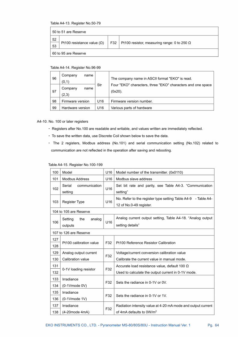
EKO INSTRUMENTS CO., LTD. - Pyranometer MS-80/80S/80U - Instruction Manual Ver. 1 Pg. 64
Table A4-13. Register No.50-79
50 to 51 are Reserve
52 Pt100 resistance value (Ω) F32 Pt100 resistor, measuring range: 0 to 250 Ω
53
60 to 95 are Reserve
Table A4-14. Register No.96-99
96 Company name
(0,1) Str
The company name in ASCII format "EKO" is read.
Four "EKO" characters, three "EKO" characters and one space
(0x20). 97 Company name
(2,3)
98 Firmware version U16 Firmware version number.
99 Hardware version U16 Various parts of hardware
A4-10. No. 100 or later registers
・ Registers after No.100 are readable and writable, and values written are immediately reflected.
・ To save the written data, use Discrete Coil shown below to save the data.
・ The 2 registers, Modbus address (No.101) and serial communication setting (No.102) related to
communication are not reflected in the operation after saving and rebooting.
Table A4-15. Register No.100-199
100 Model U16 Model number of the transmitter. (0x0110)
101 Modbus Address U16 Modbus slave address
102 Serial communication
setting U16
Set bit rate and parity, see Table A4-3. “Communication
setting”
103 Register Type U16 No. Refer to the register type setting Table A4-9 - Table A4-
12 of No.0-49 register.
104 to 105 are Reserve
106 Setting the analog
outputs U16
Analog current output setting, Table A4-18. “Analog output
setting details”
107 to 126 are Reserve
127 Pt100 calibration value F32 Pt100 Reference Resistor Calibration
128
129 Analog output current
Calibration value F32
Voltage/current conversion calibration value
Calibrate the current value in manual mode. 130
131 0-1V loading resistor F32
Accurate load resistance value, default 100 Ω
Used to calculate the output current in 0-1V mode. 132
133 Irradiance
(0-1Vmode 0V) F32 Sets the radiance in 0-1V or 0V.
134
135 Irradiance
(0-1Vmode 1V) F32 Sets the radiance in 0-1V or 1V.
136
137 Irradiance
(4-20mode 4mA) F32
Radiation intensity value at 4-20 mA mode and output current
of 4mA defaults to 0W/m2 138

EKO INSTRUMENTS CO., LTD. - Pyranometer MS-80/80S/80U - Instruction Manual Ver. 1 Pg. 65
139 Irradiance
(4-20mode 20mA) F32
Radiation intensity value at 4-20mA mode and an output
current of 20mA defaults use 1600W/m2 140
141 Manual Mode
Output current value F32 Used to calibrate the output current value
142
143 to 161 are Reserve
162 Date of manufacture U32 Date of manufacture in YYYYMMDD format
163
164
Serial number U32
Serial number with 32-bit integer value (maximum value
4294967295)
Enter the number part excluding the alphabet S. 165
166 Sensor name (0,1)
Str Sensor name according to ASCII format, up to 16 characters
Null-terminated unless all 16 characters are used
167 Sensor name (2,3)
168 Sensor name (4,5)
169 Sensor name (6,7)
170 Sensor name (8,9)
171 Sensor name (10,11)
172 Sensor name (12,13)
173 Sensor name (14,15)
174 T.Coeff.a F32 Cell temperature factor a
175
176 T.Coeff.b F32 Cell temperature factor b
177
178 T.Coeff.c F32 Cell temperature factor c
179
180 T.Coeff.d F32 Cell temperature factor d
181
182 L.Coeff.k1 F32 Linear correction factor k1
183
184 L.Coeff.k2 F32 Linear correction factor k2
185
186 L.Coeff.k3 F32 Linear correction factor k3
187
188 L.Coeff.k4 F32 Linear correction factor k4
189
190 Cal.Date U32 Calibration date in YYYYMMDD format
191
192 Cal.Value F32 Calibration value, uV/W/m2
193
194 to 199 are Reserve

EKO INSTRUMENTS CO., LTD. - Pyranometer MS-80/80S/80U - Instruction Manual Ver. 1 Pg. 66
Table A4-16. Register No.200-219
200 Cal.Date history0 U32 Calibration History, Date 0
201
202 Cal.Value history0 F32 Calibration history, sensitivity constant 0
203
204 Cal.Date history1 U32 Calibration History, Date 1
205
206 Cal.Value history1 F32 Calibration History, Sensitivity Constant 1
207
208 Cal.Date history2 U32 Calibration History, Date 2
209
210 Cal.Value history2 F32 Calibration History, Sensitivity Constant 2
211
212 Cal.Date history3 U32 Calibration History, Date 3
213
214 Cal.Value history3 F32 Calibration History, Sensitivity Constant 3
215
216 Cal.Date history4 U32 Calibration History, Date 4
217
218 Cal.Value history4 F32 Calibration History, Sensitivity Constant 4
219
Table A4-17. Analog output setting details
Analog output setting
value Operation modes
0 Output OFF
1 0-1V Mode
2 4-20 mA Mode
3 Manual Mode
A4-11. Cell temperature factor
・ When Pt100 temperature is in Celsius T (°C), use the correction factor a/b/c/d to obtain the temperature
correction value using the following equation.
・ Compensation value TC = a + b(T) + c(T2) + d(T3)
・ Calculate the solar radiation meter output after temperature correction using the following equation for the
solar radiation meter output V (raw) before temperature correction.
・ Output after temperature compensation V(T) = V(raw)/TC
・ Since the default value is a=1, b=C=d=0, the correction value TC=1 is used, and the raw value is used.
A4-12. Linear correction factor
・ Calculate the solar radiation meter output after linear correction using the following equation using the
coefficient k1/k2/k3/k4 for the solar radiation meter output V(T) after temperature correction.

EKO INSTRUMENTS CO., LTD. - Pyranometer MS-80/80S/80U - Instruction Manual Ver. 1 Pg. 67
・ Linear post-correction sun photometer output V(LT) = k1 + (k2•V(T)) + (k3•V(T) 2) + (k4•V(T) 3)
・ The default value is k2=1, k1=k3=k4=0, so V(LT)=V(T), and the raw value is used for the corrected
insolation meter output.
A4-13. Solar irradiance after correction
・ After the linear correction and temperature correction written above, using the sensitivity value S(µV/W/m2)
for the output voltage, according to the following equation, calculate the irradiance value.
Corrected solar irradiance: I(C) = V(LT) x 1000/S
*Since the unit of V(LT) is millivolts, multiply it by 1000 to obtain the irradiance value.
A4-14. Outline of Coil / Discrete Input Registers
・ Reboot the device and save the settings by writing a specified bit.
・ Do not write to any Coil other than Reboot/Save.
・ The readout is always zero.
A4-15. Register details
Table A4-18. Coil register
Addr Parameter R/W Type
0 - - -
1 Reboot W Bit
2 - - -
3 Save W Bit
4 - - -
5 - - -
6 - - -
7 - - -

EKO INSTRUMENTS CO., LTD. - Pyranometer MS-80/80S/80U - Instruction Manual Ver. 1 Pg. 68
A-5. Communicat ion Speci f icat ions (SDI -12)
A5-1. Abstract
・SDI-12 (Version:1.4) is supported.
・The initial setting of the communication interface is Modbus. To use the SDI-12 interface, change the settings
from “Hibi” software. After changing the setting, turn the power off and then on again to operate with SDI-
12 mode. To return to Modbus mode again, change the setting from “Hibi” software.
・When SDI-12 is enabled, the unit operates in "low power standby mode" with power dissipation of approx.
2.5mA (at 12V) during non-communication.
A5-2. Communication specification
・ The communication specifications of SDI-12 are as follows.
Table A5-1. SDI-12 Communication Specifications
Item Description
Communications protocols SDI-12 Version 1.4
Baud rate 1,200 bps
Data length 7bit
Stop bit 1
Parity bit Even
Communication distance Within 60 m
A5-3. Command list
・ SDI-12 commands are listed below.
・ The lowercase letter 'a' in the command list indicates SDI-12 address number.
・ SDI-12 address number that can be set is 0-9, A-Z, a-z.
Table A5-2. SDI12 Commands
Command Response Description
?! a<CR><LF> Check the address number of the connected device.
NOTE: If more than one device is connected, it will not function properly.
Be sure to use the device alone.
a! a<CR><LF> Verify that the device with address number "a" is active.
aAb! b<CR><LF> Change the address number of the device with address number "a" to "b".
aI! Refer to the
right section
Returns information.
<Response example>
"a14EKOINST_MS-80SV3220000001<CR><LF>"
a: SDI-12 address
14: SDI-12 version (represents version 1.4)
EKOInst: Company name (8 characters)
MS-80S: Sensor model name (6 characters)
V32: Sensor version (3 characters)
20000001: Serial number (8 characters)

EKO INSTRUMENTS CO., LTD. - Pyranometer MS-80/80S/80U - Instruction Manual Ver. 1 Pg. 69
aM! a0001<CR><
LF>
Request the device with address number "a" to execute measurement.
0001: indicates the 3-digit measurement execution time (000 indicates
instantaneous), and the 4th digit indicates the number of data to be
returned (1 piece).
aD0!
aD1!
aD2!
aD3!
a+1000.0<CR
><LF>
Request to send data to the device with address number "a".
The output value is always appended with a sign (+ or -).
If there is more than one output, the sign is also the delimiter.
D0: Irradiance (W/m2) 1 digit after decimal point
D1: Sensor output voltage (mV) 4 digits after decimal point and Sensor
temperature (Celsius) 2 digits after decimal point
D2: X-axis tilt angle (degree) 1 digit after decimal point, forward/backward
with connector facing back, positive value when back is up, Y-axis tilt
angle (degree) 1 digit after decimal point, left/right with connector
facing back, negative value when left is down
D3: Temperature inside enclosure (°C) 1 digit after the decimal point,
Humidity inside the enclosure (RH %) 1 digit after the decimal point.
If the pre-measurement command is “MC”, then three CRC characters are
followed, please refer to SDI-12 standard for the content of CRC
characters.
aMC! a0011<CR><
LF>
Request the device with address number "a" to start measurement and
request the CRC to confirm that the command is correctly accepted. The
response format is the same as “aM!”
aC! a00101<CR>
<LF>
This device is the same as the “aM!” command except for the difference in
the number of response characters.
The character following a indicates the number of seconds (3 digits) and
the number of data (2 digits).
aCC! a00101<CR>
<LF>
This transmitter is the same as the “aMC!” command except for the
difference in the number of response characters.
aR0! a+0.0<CR><L
F>
Request a measurement from the device with address number "a".
Measurement is executed and a response is returned immediately. The
answer is similar to “aD0!” to” aD2!” command.
aRC0! a+0.0EmT<C
R><LF>
Request measurement from the device with address number "a" and
request error detection to verify that the command was accepted correctly.
Measurement is executed and the measured value with three CRC
characters added at the end is returned instantly.
aXSE! a+XX.XX<CR
><LF>
Read the sensitivity constant of this device. Two digits after the decimal
point.
aXCD! aYYYYMMDD
<CR><LF>
Read the calibration date of this device. YYYY: AD, MM: month, DD: day.
METADATA Variable
depending on
request data
Identify Measurement Commands and Identify Measurement Parameter
Commands are supported.

EKO INSTRUMENTS CO., LTD. - Pyranometer MS-80/80S/80U - Instruction Manual Ver. 1 Pg. 70
A-6. About recal ibrat ion
When recalibrating at a recalibration center other than EKO, the calibration scale of the other center may differ
slightly from the pyranometer calibration scale and sensitivity constants (μV/Wm-2) obtained by EKO. The
differences may be caused by differences in the calibration method, differences in the reference standard,
measurement uncertainty, and measurement conditions.
If a new sensitivity constant was found and needs to be applied to the pyranometer, it can be applied in two ways:
1) (Post data correction) Multiply the relative difference of the irradiance value measured with the pyranometer.
In this case, the original factory sensitivity value given by EKO remains unchanged. When the new sensitivity
figure was found apply the ratio of the new and original calibration figure according to the formula below:
I new [W/m2] =
Example:
It was proven that there was a relative difference in irradiance measured by MS-80S and the reference
pyranometer. In this example the irradiance measured by MS-80S was lower than the irradiance measured by
the reference pyranometer, a new sensitivity value can be calculated and applied by the following equation.
Snew = IMS80S / Iref x Soriginal
S new New MS-80S Sensitivity (μV/W/m2)
Sorigin MS-80S Original Sensitivity (μV/W/m2)
I MS80S Irradiance measured by MS-80S (W/m2)
I ref Irradiance measured by reference pyranometer (W/m2)
Note: We recommend to change the sensitivity figure only when the new sensitivity figure exceeds a certain
number based on the uncertainty bands (U) of the original and new calibration according to the formula.
[Snew-Soriginal] / √[(Unew^2+Uoriginal^2 )] <1
2) (Change the sensitivity figure of the MS-80S) Set a new sensitivity figure to the MS-80S.
This can be done by done through the Hibi software. Connect the MS-80S to a PC with a RS485/USB converter
cable. In settings, the new sensitivity figure can be applied. The original sensitivity figure remains, but wil be
replaced by the “last" sensitivity figure (μV/W/m2). Multiple calibration figures can be stored inside the
pyranometer, the “last” sensitivity figure is the actual one to calculate the irradiance.
Snew [μV/W・m-2]
E [μV] Soriginal [μV/W・m-2]
Soriginal [μV/W・m-2]
X

EKO INSTRUMENTS CO., LTD. - Pyranometer MS-80/80S/80U - Instruction Manual Ver. 1 Pg. 71
A-7. Temperature sensor ( 1 0 k Ω N T C , S / N : S 1 9 0 4 6 1 5 0 o r e a r l i e r )
When determining the sensor temperature T (°C), convert the output R (resistance value, Ω) of the thermistor
(44031 10kΩ NTC) using the following equation.
T = (α + β (LN(R)) + γ (LN(R))3)-1 -273.15
T: Sensor Temperature (°C), R: Resistance Value (ohm), α: 1.0295•10 -3, α: 2.3910•10 -4, α: 1.5680•10 -7
Table A7-1. Thermistor Temperature Conversion Table (44031, 10kΩ@25°C)
T (°C) R (Ω) T (°C) R (Ω) T (°C) R (Ω)
-30
-29
-28
-27
-26
-25
-24
-23
-22
-21
-20
-19
-18
-17
-16
-15
-14
-13
-12
-11
-10
-9
-8
-7
-6
-5
-4
-3
-2
-1
135200
127900
121100
114600
108600
102900
97490
92430
87660
83160
78910
74910
71130
67570
64200
61020
58010
55170
52480
49940
47540
45270
43110
41070
39140
37310
35570
33930
32370
30890
0
1
2
3
4
5
6
7
8
9
10
11
12
13
14
15
16
17
18
19
20
21
22
23
24
25
26
27
28
29
29490
28150
26890
25690
24550
23460
22430
21450
20520
19630
18790
17980
17220
16490
15790
15130
14500
13900
13330
12790
12260
11770
11290
10840
10410
10000
9605
9227
8867
8523
30
31
32
33
34
35
36
37
38
39
40
41
42
43
44
45
46
47
48
49
50
51
52
53
54
55
56
57
58
59
8194
7880
7579
7291
7016
6752
6500
6258
6026
5805
5592
5389
5193
5006
4827
4655
4489
4331
4179
4033
3893
3758
3629
3504
3385
3270
3160
3054
2952
2854

EKO INSTRUMENTS CO., LTD. - Pyranometer MS-80/80S/80U - Instruction Manual Ver. 1 Pg. 72
A-8. MS-80 RTD Temperature Conversion Table
(Pt100 Class A)
Table A8-1. Temperature conversion table [JIS C1604-2013 conformity] of Pt100(Class A)
T [°C] R [Ω] T [°C] R [Ω] T [°C] R [Ω]
-30
-29
-28
-27
-26
-25
-24
-23
-22
-21
-20
-19
-18
-17
-16
-15
-14
-13
-12
-11
-10
-9
-8
-7
-6
-5
-4
-3
-2
-1
88.2
88.6
89.0
89.4
89.8
90.2
90.6
91.0
91.4
91.8
92.2
92.6
92.9
93.3
93.7
94.1
94.5
94.9
95.3
95.7
96.1
96.5
96.9
97.3
97.7
98.0
98.4
98.8
99.2
99.6
0
1
2
3
4
5
6
7
8
9
10
11
12
13
14
15
16
17
18
19
20
21
22
23
24
25
26
27
28
29
100.0
100.4
100.8
101.2
101.6
102.0
102.3
102.7
103.1
103.5
103.9
104.3
104.7
105.1
105.5
105.8
106.2
106.6
107.0
107.4
107.8
108.2
108.6
109.0
109.3
109.7
110.1
110.5
110.9
111.3
30
31
32
33
34
35
36
37
38
39
40
41
42
43
44
45
46
47
48
49
50
51
52
53
54
55
56
57
58
59
111.7
112.1
112.4
112.8
113.2
113.6
114.0
114.4
114.8
115.2
115.5
115.9
116.3
116.7
117.1
117.5
117.9
118.2
118.6
119.0
119.4
119.8
120.2
120.6
120.9
121.3
121.7
122.1
122.5
122.9

EKO INSTRUMENTS CO., LTD. - Pyranometer MS-80/80S/80U - Instruction Manual Ver. 1 Pg. 73
A-9. MS-80S Sett ing Report
Issue Date: 15-Aug-20
Measurement Date: 12-Jun-20
Sensor type
Model name
Serial number (S********)
Manufacuring date
Calibration date
Analog sensitivity 11.17 [µV/W/m2]
Hardware version
Firmware version (*.***)
0 - 1600 [W/m2] 4 - 20 [mA]
0 - 1600 [W/m2] 0 - 10 [mA]
Current output range Current output
Factory setting data
Pyranometer
MS-80S
19047551
June 8, 2020
June 4, 2020
11.17
7
3300
Current output range Current output
Modbus RTU Setting
Enable/Disable Enable (Default)
Address 51
Baudrate 19200
Parity EVEN
Reg. type EKO-S
Baudrate 1200
SDI-12 Setting
Enable/Disable Disenable (Default)
Address 0
S-series Setting Report

EKO Asia, Oceania
1-21-8 Hatagaya,
Shibuya-ku, Tokyo
151-0072 Japan
P. +81.3.3469.6711
F. +81.3.3469.6719
https://eko-asia.com
EKO North America
111 North Market Street,
Suite 300, San Jose,
CA 95113, USA
P. +1-408-977-7751
F. +1-408-977-7741
https://eko-usa.com
EKO Europe,
Middle East, Africa,
South America
Lulofsstraat 55, Unit 28,
2521 AL, Den Haag,
The Netherlands
P. +31 [0]70 3050117
F. +31 [0]70 3840607
https://eko-eu.com