instruction manual of operating standard lampsmetrology.hut.fi/quality/imlamp.pdf · instruction...
TRANSCRIPT
Aalto University
School of Electrical Engineering
Metrology Research Institute
Version 2.1
13/01/2017
Petri Kärhä
Jari Hovila
Pasi Manninen
Tuomas Poikonen
Tomi Pulli
Instruction Manual of Operating Standard Lamps

Instruction Manual of Operating StandardLamps
Page 2 (21)
Version: 2.1 Date: January 13, 2017 Last edited by: PK
1. Table of contents
Instruction Manual of Operating Standard Lamps .................................................. 11. Table of contents ............................................................................................. 22. Definition ........................................................................................................ 3
2.1. Scope .......................................................................................................... 32.2. Object and field of application .................................................................... 3
3. Equipment ....................................................................................................... 43.1. Photometric standard lamps ....................................................................... 4
3.1.1. Luminous intensity lamps for low illuminance level (0.1 – 500 lx) ........... 43.1.2. Luminous intensity lamps for high illuminance level (100 – 4000 lx) ....... 53.1.3. Luminous flux standard lamps ................................................................ 6
3.2. Radiometric standard lamps........................................................................ 63.2.1. FEL.......................................................................................................... 63.2.2. DXW ....................................................................................................... 7
3.3. Power supplies ............................................................................................ 84. Methods and procedures ................................................................................ 9
4.1. Assembling lamps to optical rail .................................................................. 94.2. Alignment procedures ................................................................................. 10
4.2.1. Photometric standard lamps .................................................................. 104.2.2. Radiometric standard lamps ................................................................... 12
4.3. Distance measurements .............................................................................. 154.4. Connection of the power supply ................................................................. 164.5. Soft start and soft shut down ...................................................................... 174.6. Log books .................................................................................................... 17
5. Safety and handling precautions ...................................................................... 196. Field calibrations ............................................................................................. 207. Laboratory accommodation and environment ................................................. 21

Instruction Manual of Operating StandardLamps
Page 3 (21)
Version: 2.1 Date: January 13, 2017 Last edited by: PK
2. Definition
2.1. Scope
This instruction manual describes the operation and alignment procedures for thestandard lamps used for spectral irradiance, luminous intensity and illuminance meas-urements.
2.2. Object and field of application
OSRAM Wi41/G: Standard lamp used for low-level luminous intensity and illuminancemeasurements.
OSRAM Sylvania: 1 kW standard lamp used for high-level luminous intensity and illumi-nance measurements. The lamp is operated in horizontal beam direction.
OSRAM Wi40/G Globe: Standard lamp used for luminous flux measurements.
FEL lamp: 1 kW standard lamp used for spectral irradiance measurements. The lamp isoperated in horizontal beam direction.
DXW-lamp: 1 kW standard lamp used for spectral irradiance measurements. The lampis operated in vertical beam direction.

Instruction Manual of Operating StandardLamps
Page 4 (21)
Version: 2.1 Date: January 13, 2017 Last edited by: PK
3. Equipment
3.1. Photometric standard lamps
3.1.1. Luminous intensity lamps for low illuminance level (0.1 – 500 lx)
The photometric standard lamps of Aalto used for illuminance calibrations in the rangeof 0.1 – 500 lx are of type Osram Wi41/G. The bulbs are mounted on a special lamp baseand sold by PRC Krochmann GmbH [1].
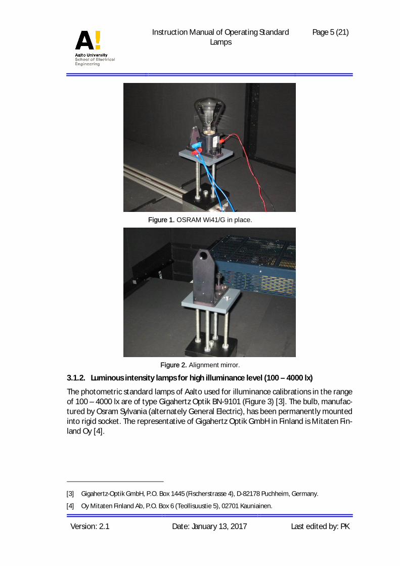
The rest of the lamp mount consists of mounting plate with adjustable mechanics on topof a rail carrier. The lamp is attached to the mounting plate by two screws. Standardlamp in place is presented in Figure 1. One side of the envelope of the lamp is coatedgrey, with only a square-shaped opening is left un-coated. The filament of the bulb canbe seen through this opening, and the lamp must be mounted in such a way that theopening faces the detector(s).
Each lamp is operated with an individual current around 5.85 A to achieve a colour tem-perature of 2856 K (CIE standard illuminant A). Precise currents and corresponding col-our temperatures for each lamp can be found in [2]. The voltage across lamp terminalsis approximately 30 V.
Two of the lamps (cds9501 and cds9905) are used as working standards, and their col-our temperatures should be checked once a year, unless the lamp has been operatedless than 15 hours since the previous check. If the nominal value of the colour tempera-ture exceeds 2856 ± 5 K, the operating current should be adjusted. This possible ± 5 Kvariation is covered by the ± 15 K expanded uncertainty of the colour temperature. Theother three lamps are for maintenance purposes and their operating currents must notbe changed.
Each lamp uses the same alignment (diffraction) mirror (Figure 2). The mirror is attachedto the mounting plate with a magnet. Alignment is performed after the lamp is put inplace.
Distances are measured using the front surface of the alignment mirror as a distancereference plane.
[1] PRC Krochmann GmbH, Wilmersdorfer Str. 39, D-10627 Berlin, Germany.
[2] Quality manual of luminous intensity laboratory.
Instruction Manual of Operating StandardLamps
Page 5 (21)
Version: 2.1 Date: January 13, 2017 Last edited by: PK
Figure 1. OSRAM Wi41/G in place.
Figure 2. Alignment mirror.
3.1.2. Luminous intensity lamps for high illuminance level (100 – 4000 lx)
The photometric standard lamps of Aalto used for illuminance calibrations in the rangeof 100 – 4000 lx are of type Gigahertz Optik BN-9101 (Figure 3) [3]. The bulb, manufac-tured by Osram Sylvania (alternately General Electric), has been permanently mountedinto rigid socket. The representative of Gigahertz Optik GmbH in Finland is Mitaten Fin-land Oy [4].
[3] Gigahertz-Optik GmbH, P.O. Box 1445 (Fischerstrasse 4), D-82178 Puchheim, Germany.
[4] Oy Mitaten Finland Ab, P.O. Box 6 (Teollisuustie 5), 02701 Kauniainen.

Instruction Manual of Operating StandardLamps
Page 6 (21)
Version: 2.1 Date: January 13, 2017 Last edited by: PK
Figure 3. BN-9101 standard lamp of Gigahertz Optik with its alignment jig.
The lamps are operated with a specified current around 7.2 A to achieve a colour tem-perature of 2856 K. The colour temperature should be checked once a year, unless thelamp has been operated less than 15 hours since the previous check. If the colour tem-perature exceeds 2856 ± 5 K, the operating current should be adjusted. A valid currentcan be found in [2]. The voltage across the lamp terminals is approximately 83 V.
3.1.3. Luminous flux standard lamps
The photometric standard lamps of Aalto used for luminous flux calibrations are of typeOsram Wi40/G Globe lamp numbered as lms9901, lms9902, lms0003, lms0004, andlms0005. The lamps have an E27 type of screw base. The lamps are operated with spec-ified currents around 5.5 – 5.8 A. The colour temperatures of the lamps are between2700 – 2750 K. The voltages across the lamp terminals are around 29 – 30 V.
3.2. Radiometric standard lamps
3.2.1. FEL
The spectral irradiance standard lamps of Aalto are all of FEL type. The lamps are oper-ated with constant current of 8.0000 A or 8.1000 A, depending on the type. The voltageacross lamp terminals is approximately 105 V. The preferred current value must beasked from the customer before operating the lamps.
Each lamp has its own alignment jig (Figure 3). The alignment jig is assembled in front ofthe lamp so that the grooved surface is pointing towards the detector(s). Distances aremeasured with respect to the reference plane that has been defined to be the frontsurface of the lamp socket (Figure 4). Other reference planes (e.g. centre of filament, orthe surface of the alignment jig) are not to be used unless specifically specified by thecustomer.

Instruction Manual of Operating StandardLamps
Page 7 (21)
Version: 2.1 Date: January 13, 2017 Last edited by: PK
Figure 4. Distance reference planes with Aalto FEL lamps.
The code of the Gigahertz Optik FEL lamps is BN-9101 Spectral Irradiance Standard Lamp(1000 W Tungsten Halogen Lamp). There are two sub-types: BN-9101-1, FEL Type(8.0000 A current); and BN-9101-2, Sylvania FEL-S.T6 Type (8.1000 A current).
The code for the alignment jig is BN-9101BA-01: Calibration Position Alignment Tar-get.
FEL lamps are operated and calibrated in horizontal orientation.
3.2.2. DXW
FMI and STUK have DXW type lamps (Figure 5).
DXW lamps are mainly operated with vertical optical axis.
The operating current is typically 8.000 A. The preferred current value must be askedfrom the customer before operating the lamps.
DXW lamps have similar alignment jigs as FEL lamps. Preferred alignment proceduresand reference planes must be asked from customers before starting calibrations.
In the optical power laboratory there is a 1-m optical stand with baffles that can be usedfor operating DXW lamps in vertical orientation.
Figure 5. DXW type lamp.
Lamp
PrecisionAperture
d=500 mm
FilterRadiometer
Instruction Manual of Operating StandardLamps
Page 8 (21)
Version: 2.1 Date: January 13, 2017 Last edited by: PK
3.3. Power supplies
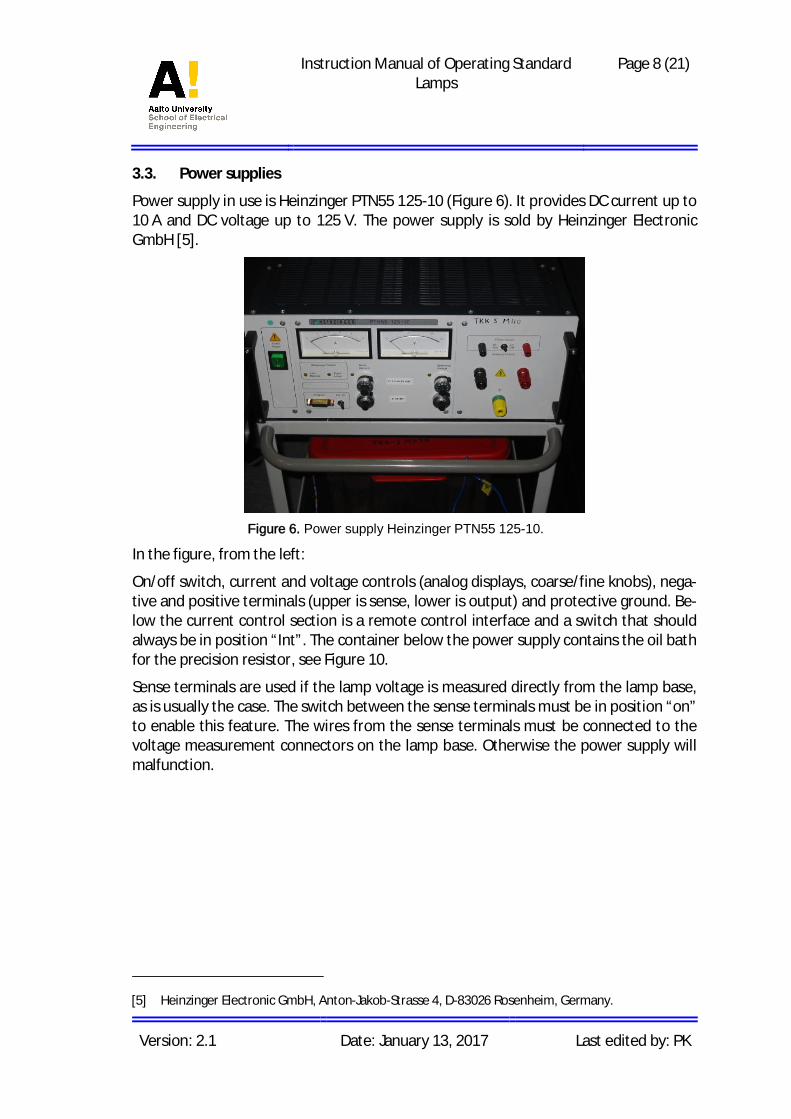
Power supply in use is Heinzinger PTN55 125-10 (Figure 6). It provides DC current up to10 A and DC voltage up to 125 V. The power supply is sold by Heinzinger ElectronicGmbH [5].
Figure 6. Power supply Heinzinger PTN55 125-10.
In the figure, from the left:
On/off switch, current and voltage controls (analog displays, coarse/fine knobs), nega-tive and positive terminals (upper is sense, lower is output) and protective ground. Be-low the current control section is a remote control interface and a switch that shouldalways be in position “Int”. The container below the power supply contains the oil bathfor the precision resistor, see Figure 10.
Sense terminals are used if the lamp voltage is measured directly from the lamp base,as is usually the case. The switch between the sense terminals must be in position “on”to enable this feature. The wires from the sense terminals must be connected to thevoltage measurement connectors on the lamp base. Otherwise the power supply willmalfunction.
[5] Heinzinger Electronic GmbH, Anton-Jakob-Strasse 4, D-83026 Rosenheim, Germany.
Instruction Manual of Operating StandardLamps
Page 9 (21)
Version: 2.1 Date: January 13, 2017 Last edited by: PK
4. Methods and procedures
4.1. Assembling lamps to optical rail
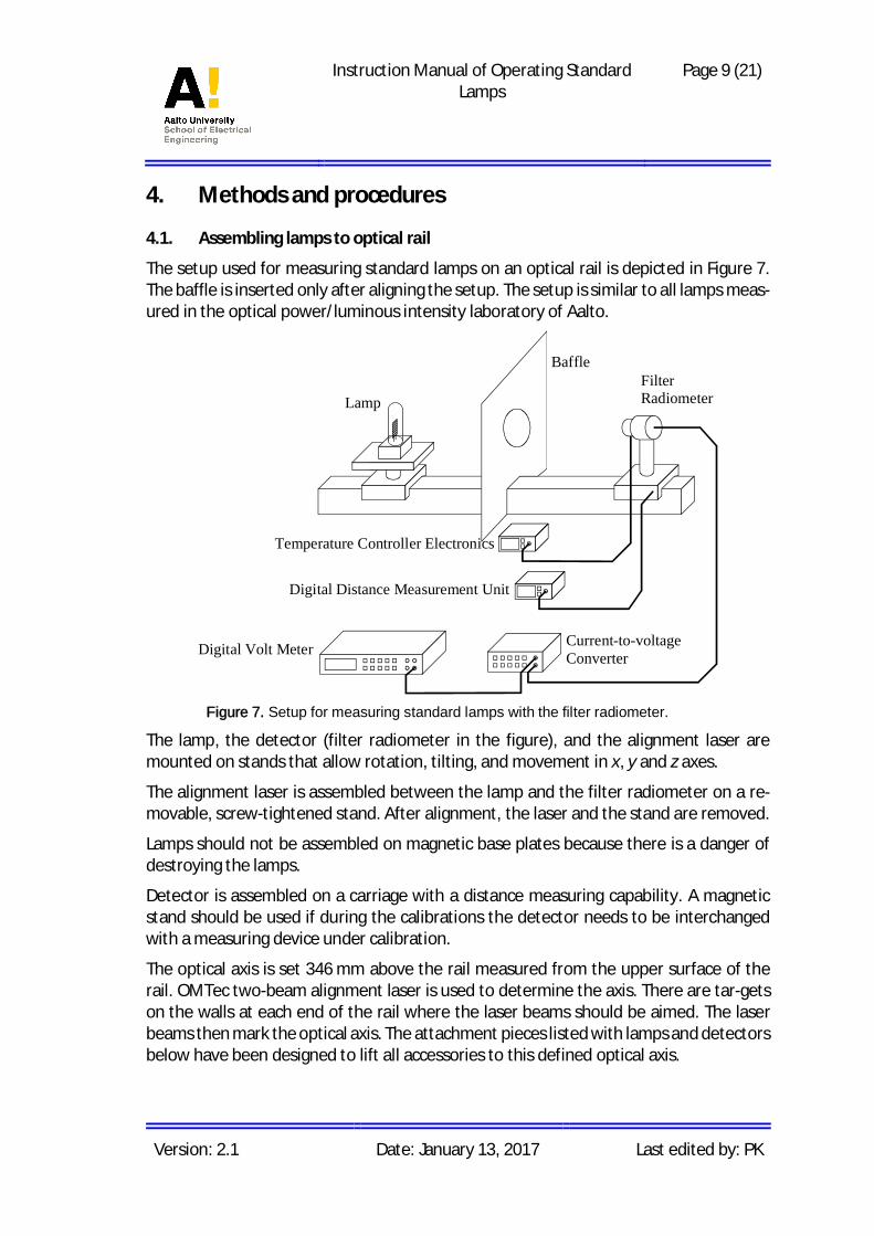
The setup used for measuring standard lamps on an optical rail is depicted in Figure 7.The baffle is inserted only after aligning the setup. The setup is similar to all lamps meas-ured in the optical power/luminous intensity laboratory of Aalto.
Figure 7. Setup for measuring standard lamps with the filter radiometer.
The lamp, the detector (filter radiometer in the figure), and the alignment laser aremounted on stands that allow rotation, tilting, and movement in x, y and z axes.
The alignment laser is assembled between the lamp and the filter radiometer on a re-movable, screw-tightened stand. After alignment, the laser and the stand are removed.
Lamps should not be assembled on magnetic base plates because there is a danger ofdestroying the lamps.
Detector is assembled on a carriage with a distance measuring capability. A magneticstand should be used if during the calibrations the detector needs to be interchangedwith a measuring device under calibration.
The optical axis is set 346 mm above the rail measured from the upper surface of therail. OMTec two-beam alignment laser is used to determine the axis. There are tar-getson the walls at each end of the rail where the laser beams should be aimed. The laserbeams then mark the optical axis. The attachment pieces listed with lamps and detectorsbelow have been designed to lift all accessories to this defined optical axis.
Lamp
BaffleFilterRadiometer
Current-to-voltageConverterDigital Volt Meter
Temperature Controller Electronics
Digital Distance Measurement Unit

Instruction Manual of Operating StandardLamps
Page 10 (21)
Version: 2.1 Date: January 13, 2017 Last edited by: PK
Prior to measurements, the alignment of the laser beam on the targets on the walls ischecked. A photometer or a filter radiometer is aligned with the laser. The carriage car-rying the meter is then moved along the rail, at least in the distance range that is to beused. If properly aligned, the laser hits the centre of the meter at any position. If align-ment can’t be achieved, the targets on the walls may have moved and need realignment.
The positions of the targets are aligned with the two-beam alignment laser, attached ona moving roller carriage, and two iris diaphragms. The irises are mounted at both endsof the rail, directly on top and in the centre of it at the height of 346 mm. The two laserbeams are aligned to the centres of the irises. The carriage supporting the laser is thenmoved along the rail (z-direction). With proper alignment, the laser beams should hitthe irises at any position of the laser. If not, the x- and y-positions of the irises are fine-tuned. After receiving satisfactory alignment, the targets are attached on the walls tonote the laser positions.
The purpose of the baffle(s) is to avoid light from the lamp reaching the detector indi-rectly through reflections from the rail, the walls, or other surfaces. Generally, the open-ing of the baffle should be as small as possible to give best protection. However, theopening should be large enough so as not to cause vignetting. This can be verified bylooking at the lamp filament from the direction of the detector. The filament has to befully visible to the detector input at all measurement distances.
4.2. Alignment procedures
4.2.1. Photometric standard lamps
4.2.1.1. OSRAM Wi41/G
These lamps are aligned perpendicular to the rail using a diffraction mirror. A magnetkeeps the mirror in place and improves repeatability of the alignment. All devices canbe aligned to the optical axis using the following optical mounts (from bottom upwards):
Lamp: Rail carrier (no distance measurement sensor), adapter plate, lineartranslator, rotation platform, dual axis goniometer, 75 mm post holder,50 mm post + collar (M6 thread upwards), mounting plate. No magneticbase plate!
Laser: Screw-tightened stand, 150 mm post holder, 200 mm post + collar, smalltilt stage.
Detectors: Reference photometer: rail carrier with distance measurement sensor,adapter plate, magnetic base plate (optional), 150 mm post holder, 150mm post + collar, large tilt stage, 50 mm post (M4 thread upwards).
PRC photometer: rail carrier with distance measurement sensor, adapterplate, magnetic base plate (optional), 75 mm post holder, 75 mm post +collar, large tilt stage, 75 mm post (M6 thread upwards).
Alignment procedure:

Instruction Manual of Operating StandardLamps
Page 11 (21)
Version: 2.1 Date: January 13, 2017 Last edited by: PK
· Set suitable distance between the lamp mount and the photometer* carrier (about1.5 m). Insert the OMTec alignment laser and its stand in halfway between the lampand the photometer.
· Before assembling the lamp and the photometer, align the OMTec alignment laserin such a way that the two laser beams hit the targets on the walls at the both endsof the optical bench. The laser beam now marks the optical axis, which is parallel tothe optical rail and 35 cm above it.
· Put the photometer and the lamp in place and attach the diffraction mirror to thelamp mount.
· Guide the laser beam to the centre of the photometer (into the centre of the aper-ture and filter) by adjusting the position of the photometer. Align the photometerso that the reflected beam is returned back to the centre of the alignment laser.
· Guide the opposite laser beam to the centre of the diffraction mirror by adjustingthe position of the lamp mount. Align the lamp mount so that the centre of the re-flected diffraction pattern hits the centre of the alignment laser output.
· Loosen the screws of the laser stand and remove the alignment assembly.
· Move the photometer towards the lamp so that the reference planes (front surfacesof the diffraction mirror and the photometer) slightly contact.
· Zero the length measurement unit. Move the photometer farther from the lamp andrepeat the previous step a couple of times to make sure that the distance is resetproperly. Remove the diffraction mirror.
· Move the photometer to its correct measurement distance. Take into account the3.0 mm distance between the front surface of the photometer and the apertureplane and the distance offset of the particular lamp. These values and measurementprocedures for HUT/MRI photometric calibrations are found in [2].
· Place one baffle between the lamp and the photometer close to the lamp (about25 – 30 cm). The diameter of the baffle should be 40 – 50 mm.
The lamp and the photometer are now aligned and ready for measurements.
Note: The alignment of the lamp mount needs to be checked each time a lamp is re-placed, since removing and attaching the lamp may affect the alignment.
* In photometry, filter radiometer is called reference photometer. For simplicity, both reference pho-tometer and PRC-photometer (secondary standard) are referred as “photometer”.
4.2.1.2. Osram Sylvania
Osram Sylvania lamp is aligned perpendicular to the rail using the alignment jig. Thegrooved surface of the alignment jig must be pointed away from the lamp (towards thephotometer). All devices can be aligned to the optical axis using the following opticalmounts (from bottom upwards):

Instruction Manual of Operating StandardLamps
Page 12 (21)
Version: 2.1 Date: January 13, 2017 Last edited by: PK
Lamp: Rail carrier (no distance measurement sensor), adapter plate, lineartranslator, rotation platform, dual axis goniometer, 75 mm post holder,75 mm post + collar (M6 thread upwards), mounting plate. No magneticbase plate!
Laser: As with Wi41/G.
Detectors: As with Wi41/G.
Alignment procedure:
· Insert and align the OMTec alignment laser as described above.
· Insert the photometer and the lamp into their places and attach the alignment jig tothe lamp.
· Use the back-reflection from the centre of the alignment jig to align the lamp. Therest of the alignment process is described above.
4.2.2. Radiometric standard lamps
4.2.2.1. FEL
Figure 8. Alignment of FEL lamps using the alignment jig and the OMTec dual-beam align-ment laser.
FEL lamps are aligned perpendicular to the rail using the alignment jig (Figure 8). Thegrooved surface of the alignment jig must be pointed away from the lamp (towards thefilter radiometer). The optical axis is marked with white targets on both ends of the rail.All devices can be aligned to the optical axis using the following optical mounts (frombottom upwards):

Instruction Manual of Operating StandardLamps
Page 13 (21)
Version: 2.1 Date: January 13, 2017 Last edited by: PK
Lamp: Rail carrier (no distance measurement sensor), adapter plate, lineartranslator, rotation platform, dual axis goniometer, 75 mm post holder,75 mm post + collar (M6 thread upwards), mounting plate. No magneticbase plate!
Laser: Screw-tightened stand, 150 mm post holder, 200 mm post + collar, smalltilt stage.
Detectors: Filter radiometer: rail carrier with distance measurement sensor, adapterplate, 150 mm post holder, 150 mm post + collar, large tilt stage, 50 mmpost (M4 thread upwards).
Alignment procedure:
· Insert the OMTec alignment laser halfway between the lamp and the filter radiome-ter.
· Before assembling the lamp and the filter radiometer, align the Omtec alignmentlaser in such a way that the two laser beams hit the targets glued in the walls at theboth ends of the optical bench. The laser beam is now in the optical axis.
· Insert the filter radiometer and the lamp into their places. Insert the alignment jig tothe lamp.
· Insert the 900 nm filter (900c) into the filter radiometer.
· Guide the laser to the centre of the filter radiometer (into the centre of the apertureand filter) by adjusting the position of the filter radiometer. Align the filter radiome-ter so, that the reflected beam is returned back to the centre of the alignment laser.
· Guide the other laser to the centre of the alignment jig of the lamp by adjusting theposition of the lamp. Align the lamp so, that the reflected beam is returned back tothe centre of the alignment laser.
· Remove the alignment laser. Remove the alignment jig.
· Place the filter radiometer as close as possible to the lamp and measure the distancebetween the reference plane and the filter radiometer with a calibrated length rod.A suitable length for the rod is 150 mm. The rod should be placed between the frontsurface of the filter radiometer and the front surface of the lamp socket (referenceplane, see Figure 4).
· Zero the length measurement unit.
· Move the filter radiometer to its correct measurement distance. Take into accountthe length of the rod used, and the distance between the front surface of the filterradiometer and the aperture plane (3.0 mm for FR1997 and FR2001).
· The measurement distance for Aalto FEL lamps is 500 mm. Measurement distancewith customer lamps has to be asked.

Instruction Manual of Operating StandardLamps
Page 14 (21)
Version: 2.1 Date: January 13, 2017 Last edited by: PK
· Place one baffle between the lamp and the filter radiometer approximately halfwaybetween the lamp and the detector. Suitable size for the opening of the baffle isapproximately 50 mm.
The lamp and the filter radiometer are now aligned and ready for measurements.
4.2.2.2. DXW
DXW lamps are calibrated with a 1-m vertical rail (Figure 9). Please note that the opticalbreadboard has to be earthed to the protective earth of the power line to reduce elec-trical disturbances at low signal levels! This can be accomplished with a short wire con-necting the breadboard to the protective earth pins of a nearby Schuko socket using analligator clip.
Figure 9. Components assembled on the 1-m vertical optical rail for calibration of a DXWlamp.
All devices can be aligned to the optical axis (273 mm from the rail surface) using thefollowing optical mounts (from bottom upwards):
1. Filter radiometer: 75 mm holder, 75 mm post + collar, tilt stage, 100 mm post (M4thread upwards).
2. Baffle: 75 mm holder, 75 mm post (+ collar).

Instruction Manual of Operating StandardLamps
Page 15 (21)
Version: 2.1 Date: January 13, 2017 Last edited by: PK
3. Laser: 75 mm post holder, 200 mm post + collar, tilt stage.
4. Lamp: 50 mm post holder, 75 mm post + collar, tilt stage, 50 mm post (M6 threadupwards).
5. Stray light shield above lamp: 75 mm holder, 75 mm post (+ collar).
Alignment procedure:
· Place the rail in the optical table. Ensure straightness of the rail with a spirit level(vatupassi).
· Attach lamp to the top of the rail.
· Insert filter radiometer to the bottom of the rail.
· Align as with FEL lamps using the alignment jig and the OMTec laser.
· Lock the tilt stages of the lamp and the filter radiometer e.g. with clamps. Otherwisethe stages may tilt due to the load of the devices.
· Distance is measured with a ruler. Check the scale by drawing two lines to the opticalbench and measuring their distance with both the ruler, and the magnetic lengthscale. The latter is traceable to the length scale of MIKES.
· Place one baffle between the lamp and the filter radiometer.
· Place the black sheet (looks like a baffle but with no opening) behind the lamp at 45degree angle (see Figure 9). This reduces back-reflections from the ceiling. Pleasenote that the anodised aluminium reflects IR radiation from approximately 700 nmupwards. This has no effect on the UV calibrations, but needs to be taken into ac-count if near-IR region is to be measured.
DXW lamps are customer lamps. Before starting calibrations, ask the customer to specifythe required measurement distance, the reference plane, and the operating current. Askalso the last measured voltage for the lamp. Fill in customer log books and apply theirquality assurance procedures if necessary.
4.3. Distance measurements
In most of the calibrations on the 4.5-m optical bench, distances are measured with theelectro-magnetic distance measurement system. There is a magnetic ruler in the rail.Rail carriers are equipped with sensors, and a display shows location with 0.1-mm reso-lution.
Distances are often defined with respect to a reference plane, which is typically the frontsurface of the lamp housing. In such case, the filter radiometer on a rail carrier is placedin contact with the reference plane, and the display is zeroed. A calibrated length rodmay be used in between. The length of the rod, and the 3-mm recess of the apertureare accounted for.

Instruction Manual of Operating StandardLamps
Page 16 (21)
Version: 2.1 Date: January 13, 2017 Last edited by: PK
If the reference plane of the lamp has been defined to be the centre of the filament, a1-m auxiliary optical rail and a telescope attached on a rail carrier is used to transfer thereference plane out of the lamp. The auxiliary rail is assembled parallel to the main rail.The telescope on a rail carrier on the auxiliary rail is set so that the center of the filamentis seen through the telescope, and the distance display is zeroed. The rail carrier is thenmoved so that a suitable reference plane, e.g. the front surface of the lamp, is seenthrough the telescope, and the distance offset is noted. After that, distances can bemeasured with respect to the new reference surface. If the lamp has no suitable externalreference plane, the distance between the lamp filament and the filter radiometer mayalso be directly measured and set with the telescope.
4.4. Connection of the power supply
Connection of the power supply is depicted in Figure 10. The connection is the same forall lamps measured in the optical power/luminous intensity laboratory. Extreme careshould be taken to use correct polarity of the current!
The power supply is operated in current controlled mode. The operating current is meas-ured by using a precision resistor. The voltage drop across the single value precisionresistor is used to determine the current with an accuracy of 0.001 %.
Figure 10. Connection of the lamp, power supply and the associated electronics. If only oneDVM is available, lamp voltage and currents are coupled to the front and rear terminals.
+
-
0.5901 V
30.5 V
Power supply
DVM
DVM100 mWresistor
+
- -
Oil bath
Lamp
+-
Sense

Instruction Manual of Operating StandardLamps
Page 17 (21)
Version: 2.1 Date: January 13, 2017 Last edited by: PK
4.5. Soft start and soft shut down
The lamps should not be turned on or off instantly. Current needs to be ramped up anddown slowly. Soft start and soft shut down are accomplished using the current limit ofthe power supply.
· Before switching the power supply on, check that both the coarse and fine-tuning(current) knobs of the power supply are in zero-position. Check also the polarity ofthe lamp terminals (red cables should go to the terminals marked with “+”) and thatthe alignment target has been removed from the lamp base.
· Raise the fine-tuning knob gradually to position 5.0.
· Raise the current with the coarse-tuning knob gradually so that the current reachesits nominal value (e.g. 8.1 A) in approximately 2 minutes.
· Allow lamps output stabilise for minimum 20 minutes, or as the customer has spec-ified. During this period, light must be blocked so that it does not irradiate the filters,if filter radiometer is used.
· Monitor the lamp current and lamp voltage during the warm-up. The lamp voltagemust not deviate from its earlier value by more than about 0.1 V.
· After the lamp has stabilised, use the fine-tuning to set the current to its exact value.It is possible to obtain accuracy of 10-5 in the current setting (e.g. 8.1000 A).
Switching off takes place according to the same scheme, but in reverse order.
4.6. Log books
Log books are kept for all lamps. The log books are stored with the lamps. FEL lamps arestored with their alignment targets and log books in grey flight cases in the opticalpower/luminous intensity laboratory. Photometric lamps with their log books are storedin the closet in the corner of the laboratory.
The log books contain the operating currents for the lamps. The following data are filledin each time when burning the lamps:
· Date
· Time for switching the lamp on and off
· Burn hours during the measurement session
· Total (cumulative) burn hours for the lamp
· Voltage in the beginning and at the end of the session (the begin voltage is the firstvoltage measurement after the stabilising period)
· Operator initials

Instruction Manual of Operating StandardLamps
Page 18 (21)
Version: 2.1 Date: January 13, 2017 Last edited by: PK
· All unexpected events and observations on the lamps are written to the log books.These may include sudden appearance of dirt in the lamp envelope, change of thelamp voltage, sudden power break down, accidental wrong polarity.

Instruction Manual of Operating StandardLamps
Page 19 (21)
Version: 2.1 Date: January 13, 2017 Last edited by: PK
5. Safety and handling precautions
· 1 kW lamps operated at 8.1 A produce lots of UV radiation. Avoid staring to thelamps. Use protective clothing and limit staying in the vicinity of the lamp to min-imum.
· Never move hot lamps. They may explode or the filaments may damage! Allowlamp to cool down for a minimum of 2 hours before disassembling the setup.
· Do not touch the envelopes of the lamps. If you notice finger prints in the glass,it is important to know, whether they are fresh or older stains. Check the lamplog and the latest calibration certificate to see whether they mention the stain.If it is an old stain, do not attempt to clean it. If it is fresh, clean it with ethanolor isopropanol as well as you can. Write down the operation and describe thefinal condition of the lamp to the log book and to the next calibration certificate.
· Before operating, the dust should be removed with soft brush or by blowingclean air.
· Do not touch the surfaces of the filters or the edges of the apertures.
· If, by accident, any optical component gets dirty or damaged, notify all colleagueswho might be using the equipment. In case of damage to the lamps, record theincidence to the log book.
· If transported abroad (intercomparisons) the lamps are to be hand-carried intheir cases. Avoid any kind of shocks to the cases.
· Before flying, write a certificate on the contents of the case (emphasize that thelamps are completely harmless) have it signed by the head of the national stand-ards laboratory or the head of department, and get university stamp for the cer-tificate (from kanslia). This is to ensure that the security officers at the airport donot open the lamps.
· The standard lamps should not be operated if there is a possibility of losing theelectricity during the measurement, e.g., during a thunderstorm or servicebreakdown. If the electricity is lost during a measurement, the lamp power sup-ply and other critical devices must be turned off immediately to prevent dam-ages when the electricity is restored.
Instruction Manual of Operating StandardLamps
Page 20 (21)
Version: 2.1 Date: January 13, 2017 Last edited by: PK
6. Field calibrations
Field calibrations may be done for certain customers, e.g. STUK and FMI. Quality assur-ance routines and operating instructions of the customers are to be followed. This con-cerns e.g.
· Operation of the customer lamps, including current and voltage monitoring.
· Control and monitoring of environmental conditions.
· Alignment and distance measuring.
The procedures used should be recorded to the calibration certificates with care, andthe effect of deviations should be estimated and added to the uncertainty budgets.

Instruction Manual of Operating StandardLamps
Page 21 (21)
Version: 2.1 Date: January 13, 2017 Last edited by: PK
7. Laboratory accommodation and environment
The spectral irradiance and luminous intensity measurements are done mainly in theOptical Power Laboratory, which is located in room I136 in the basement of the Depart-ment of Signal Processing and Acoustics. This laboratory is a clean room. Instructions forusing the clean rooms have been given in [6].
During calibrations:
· The Clean Zone aggregate should be on to prevent dust.
· Temperature should be monitored.
· Humidity should be monitored.
Humidity and temperature values during the calibrations are written to calibration cer-tificates.
Optical components such as interference filters, V(λ) filters and photodiodes may sufferfrom high humidity. If humidity exceeds 70 % R.H. these components are not to be takenout from the dry cabinet in the corridor of the laboratory. Frictional electricity may dam-age electronics with very dry conditions, so humidity during measurements should be15 – 70 %. Temperature should be within 18 – 27 °C. These limits are applied to all pho-tometric and radiometric calibrations unless otherwise stated in the correspondingQuality or Instruction Manuals. Measurements are either postponed, or the conditionsmay be improved with heating, cooling, humidifiers, or dryers.
Measurements with the filter radiometer may also be done outside the university. Thesefield measurements should be done in corresponding laboratory conditions.
[6] Clean room instructions / Puhdastilaohjeet.