operating instruction grte18
TRANSCRIPT

O P E R A T I N G I N S T R U C T I O N
GRTE18
Round photoelectric sensors

B E T R I E B S A N L E I T U N G
GRTE18
Rund-Lichtschranken
de
en
es
fr
it
ja
pt
ru
zh

Described product
GR18
GRTE18
Manufacturer
SICK AGErwin-Sick-Str. 179183 WaldkirchGermany
Production location
Legal information
This work is protected by copyright. Any rights derived from the copyright shall bereserved for SICK AG. Reproduction of this document or parts of this document isonly permissible within the limits of the legal determination of Copyright Law. Any modi‐fication, abridgment or translation of this document is prohibited without the expresswritten permission of SICK AG.
The trademarks stated in this document are the property of their respective owner.
© SICK AG. All rights reserved.
Original document
This document is an original document of SICK AG.
2006/42/EC
NO
SAFETY
8016953.1ABM / 2020-12-21 | SICKSubject to change without notice 3

Contents
1 General safety notes......................................................................... 5
2 Notes on UL approval........................................................................ 5
3 Correct use......................................................................................... 5
4 Commissioning.................................................................................. 54.1 Check the application conditions............................................................ 54.2 Mounting................................................................................................... 74.3 Electronics................................................................................................. 84.4 Alignment.................................................................................................. 84.5 Adjustment................................................................................................ 9
5 Troubleshooting................................................................................. 10
6 Disassembly and disposal............................................................... 11
7 Maintenance...................................................................................... 11
8 Technical specifications................................................................... 118.1 Dimensional drawings.............................................................................. 12
CONTENTS
4 8016953.1ABM / 2020-12-21 | SICKSubject to change without notice
1 General safety notes
■ Read the operating instructions before commissioning.■
Connection, mounting, and configuration may only be performed by trainedspecialists.
■2006/42/EC
NO
SAFETY Not a safety component in accordance with the EU Machinery Directive.■
Do not install the sensor at locations that are exposed to direct sunlightor other weather influences, unless this is expressly permitted in the operatinginstructions.
■ These operating instructions contain information required during the life cycle ofthe sensor.
2 Notes on UL approval
UL: Only for use in applications in accordance with NFPA 79. These devices shall beprotected by a 1 A fuse suitable for 30 V DC.
Adapters listed by UL with connection cables are available.
Enclosure type 1.
3 Correct use
The GRTE18 is an opto-electronic photoelectric proximity sensor (referred to as "sensor"in the following) for the optical, non-contact detection of objects, animals, and persons.If the product is used for any other purpose or modified in any way, any warranty claimagainst SICK AG shall become void.
Energetic photoelectric proximity sensor
4 Commissioning
4.1 Check the application conditions
Check the application conditions: Adjust the sensing range and the remission capabilityof the object according to the corresponding diagram [H] (x = sensing range, y =operating reserve).During this process, an object can only be detected in front of a background if theremission capability of the object is significantly higher than that of the background or ifthe distance between the object and the background is sufficiently long.
GENERAL SAFETY NOTES 1
8016953.1ABM / 2020-12-21 | SICKSubject to change without notice 5

1
mm(inch)
20(0.79)
40(1.57)
60(2.36)
80(3.15)
100(3.94)
120(4.72)
140(5.51)
100
10
Operating reserve
Distance in mm (inch)
1 2 3
Figure 1: H: Sensing range 115 mm
1mm
(inch)100
(3.94)200
(7.87)300
(11.81)400
(15.75)500
(19.69)600
(23.62)
100
10
Operating reserve
Distance in mm (inch)
1 2 3
Figure 2: H: Sensing range 550 mm
4 COMMISSIONING
6 8016953.1ABM / 2020-12-21 | SICKSubject to change without notice

0 200(7.87)
400(15.75)
600(23.62)
800(31.5)
1,000(39.37)
100
10
1
Operating reserve
Distance in mm (inch)
2
1
3
Figure 3: H: Sensing range 800 mm
4.2 Mounting
Mount the sensor using a suitable mounting bracket (see the SICK range of acces‐sories).
Observe the maximum permissible tightening torque of the sensor of 2.0 Nm formetal/0.9 Nm for plastic [K].
Figure: K: GRTE18-x24x7
Figure: K: GRTE18-x24x2
COMMISSIONING 4
8016953.1ABM / 2020-12-21 | SICKSubject to change without notice 7

4.3 Electronics
The sensors must be connected in a voltage-free state (VS = 0 V). The information in thegraphics [B] must be observed, depending on the type of connection:
– Male connector connection: pin assignment– Cable: core color
+ (L+)
Q
- (M)
brn
wht
blu
blk
1
2
3
Q4
Figure: B: GRTE18-x24xx
+ (L+)
Q
- (M)
brn
wht
blu
Qblk
Figure: B: GRTE18-x11xx, -x12xx
Only apply voltage/switch on the power supply (VS > 0 V) once all electrical connectionshave been completed. The green LED indicator lights up on the sensor.
Explanations of the connection diagram (Graphic B):
Switching outputs Q and /Q (according to Graphic B):
GRTE18-P (PNP: load -> M)
GRTE18-N (NPN: load -> L+)
4.4 Alignment
Align the sensor with the object. Select the position so that the red emitted light beamhits the center of the object. You must ensure that the optical opening (front screen) ofthe sensor is completely clear [see figure 4].
Figure 4: Alignment
4 COMMISSIONING
8 8016953.1ABM / 2020-12-21 | SICKSubject to change without notice

4.5 Adjustment
y x
Figure: F
Sensor with potentiometer:
The sensitivity (sensing range) is adjusted with the potentiometer (type: 270°). Clock‐wise rotation: sensitivity (sensing range) increased; counterclockwise rotation: sensitiv‐ity (sensing range) reduced. We recommend placing the switching state in the object, e.g., see graphic F. Once the sensitivity has been adjusted, the object is removed from thepath of the beam. The switching output changes (see graphic C).
The sensor is adjusted and ready for operation. Refer to graphics C and G to check thefunction. If the switching output fails to behave in accordance with graphic C, checkapplication conditions. See section Fault diagnosis.
Q
(PNP)
(NPN)
Q
q 10
q
10
10
10
Figure: C
COMMISSIONING 4
8016953.1ABM / 2020-12-21 | SICKSubject to change without notice 9
Figure: G
5 Troubleshooting
The Troubleshooting table indicates measures to be taken if the sensor stops working.
Table Fault diagnosis
LED indicator/fault pattern Cause Measures
Green LED does not light up No voltage or voltage belowthe limit values
Check the power supply,check all electrical connec‐tions (cables and plug connec‐tions)
Green LED does not light up Voltage interruptions Ensure there is a stable powersupply without interruptions
Green LED does not light up Sensor is faulty If the power supply is OK,replace the sensor
Yellow LED flashes Sensor is still ready for oper‐ation, but the operating condi‐tions are not ideal
Check the operating condi‐tions: Fully align the beamof light (light spot) with theobject. / Clean the optical sur‐faces . / Readjust the sensi‐tivity (potentiometer) / Checksensing range and adjustif necessary, see „Checkthe application conditions“,page 5.
Yellow LED lights up, no objectin the path of the beam
Excessive background remis‐sion
Check changes to the back‐ground. Reduce the sensitivityof the sensor or use sensorswith background suppression
Object is in the path of thebeam, yellow LED does notlight up
Sensitivity is set too low or dis‐tance between the sensor andthe object is too long
Increase the sensing range,take note of the distancebetween the sensor and thebackground
Object is in the path of thebeam, yellow LED does notlight up
Remission capability of theobject is insufficient
Increase the sensing range,take note of the distancebetween the sensor and thebackground
4 COMMISSIONING
10 8016953.1ABM / 2020-12-21 | SICKSubject to change without notice

6 Disassembly and disposal
The sensor must be disposed of according to the applicable country-specific regula‐tions. Efforts should be made during the disposal process to recycle the constituentmaterials (particularly precious metals).
NOTEDisposal of batteries, electric and electronic devices• According to international directives, batteries, accumulators and electrical or
electronic devices must not be disposed of in general waste.• The owner is obliged by law to return this devices at the end of their life to the
respective public collection points.•
WEEE: This symbol on the product, its package or in this document,indicates that a product is subject to these regulations.
7 Maintenance
SICK sensors are maintenance-free.
We recommend doing the following regularly:
• Clean the external lens surfaces• Check the screw connections and plug-in connections
No modifications may be made to devices.
Subject to change without notice. Specified product properties and technical data arenot written guarantees.
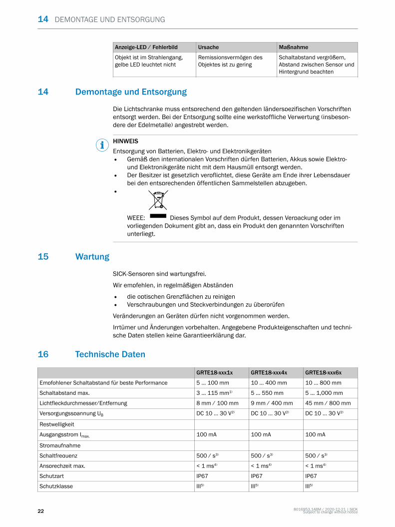
8 Technical specifications
GRTE18-xxx1x GRTE18-xxx4x GRTE18-xxx6x
Recommended sensing range for the best performance 5 ... 100 mm 10 ... 400 mm 10 ... 800 mm
Sensing range max. 3 ... 115 mm1) 5 ... 550 mm 5 ... 1,000 mm
Light spot diameter/distance 8 mm / 100 mm 9 mm / 400 mm 45 mm / 800 mm
Supply voltage UB DC 10 ... 30 V2) DC 10 ... 30 V2) DC 10 ... 30 V2)
Ripple
Output current Imax. 100 mA 100 mA 100 mA
Current consumption
Switching frequency 500 / s3) 500 / s3) 500 / s3)
Max. response time < 1 ms4) < 1 ms4) < 1 ms4)
Enclosure rating IP67 IP67 IP67
Protection class III5) III5) III5)
Circuit protection A, B, D6) A, B, D6) A, B, D6)
DISASSEMBLY AND DISPOSAL 6
8016953.1ABM / 2020-12-21 | SICKSubject to change without notice 11

GRTE18-xxx1x GRTE18-xxx4x GRTE18-xxx6x
Ambient operating temperature -25 °C ... +55 °C -25 °C ... +55 °C -25 °C ... +55 °C
1) Object with 90 % remission (based on standard white DIN 5033)2) Limit values. UB connections reverse-polarity protected. Residual ripple max 5 VPP3) With light / dark ratio 1:14) Signal transit time with resistive load5) Reference voltage DC 50 V6) A = UB-connections reverse polarity protected
B = inputs and output reverse-polarity protectedD = outputs overcurrent and short-circuit protected
8.1 Dimensional drawings
Figure 5: GRTE18-xxxx2
Figure 6: GRTE18-xxxx7
8 TECHNICAL SPECIFICATIONS
12 8016953.1ABM / 2020-12-21 | SICKSubject to change without notice

B E T R I E B S A N L E I T U N G
GRTE18
Rund-Lichtschranken
de
en
es
fr
it
ja
pt
ru
zh

Beschriebenes Produkt
GR18
GRTE18
Hersteller
SICK AGErwin-Sick-Str. 179183 WaldkirchDeutschland
Fertigungsstandort
Rechtliche Hinweise
Dieses Werk ist urheberrechtlich geschützt. Die dadurch begründeten Rechte bleibenbei der Firma SICK AG. Die Vervielfältigung des Werks oder von Teilen dieses Werksist nur in den Grenzen der gesetzlichen Bestimmungen des Urheberrechtsgesetzeszulässig. Jede Änderung, Kürzung oder Übersetzung des Werks ohne ausdrücklicheschriftliche Zustimmung der Firma SICK AG ist untersagt.
Die in diesem Dokument genannten Marken sind Eigentum ihrer jeweiligen Inhaber.
© SICK AG. Alle Rechte vorbehalten.
Originaldokument
Dieses Dokument ist ein Originaldokument der SICK AG.
2006/42/EC
NO
SAFETY
14 8016953.1ABM / 2020-12-21 | SICKSubject to change without notice

Inhalt
9 Allgemeine Sicherheitshinweise..................................................... 16
10 Hinweise zur UL Zulassung.............................................................. 16
11 Bestimmungsgemäße Verwendung............................................... 16
12 Inbetriebnahme................................................................................. 1612.1 Einsatzbedingungen prüfen..................................................................... 1612.2 Montage.................................................................................................... 1812.3 Elektronik.................................................................................................. 1912.4 Ausrichtung............................................................................................... 1912.5 Einstellung................................................................................................. 20
13 Störungsbehebung............................................................................ 21
14 Demontage und Entsorgung............................................................ 22
15 Wartung.............................................................................................. 22
16 Technische Daten.............................................................................. 2216.1 Maßzeichnungen...................................................................................... 23
INHALT
8016953.1ABM / 2020-12-21 | SICKSubject to change without notice 15

9 Allgemeine Sicherheitshinweise
■ Lesen Sie vor der Inbetriebnahme des Geräts die Betriebsanleitung.■
Der Anschluss, die Montage und die Konfiguration des Geräts dürfen nurvon geschultem Fachpersonal vorgenommen werden.
■2006/42/EC
NO
SAFETY Bei diesem Gerät handelt es sich um kein sicherheitsgerichtetes Bauteil imSinne der EU-Maschinenrichtlinie.
■
Installieren Sie den Sensor nicht an Orten, die direkter Sonneneinstrahlungoder sonstigen Wettereinflüssen ausgesetzt sind, ausser dies ist in der Betriebs‐anleitung ausdrücklich erlaubt.
■ Die vorliegende Betriebsanleitung enthält Informationen, die während des Lebens‐zyklus der Lichtschranke benötigt werden.
10 Hinweise zur UL Zulassung
UL: Nur zur Verwendung in Anwendungen gemäß NFPA 79. Diese Geräte müssen miteiner für 30V DC geeigneten 1A-Sicherung abgesichert werden.
Von UL gelistete Adapter mit Anschlusskabeln sind verfügbar.
Enclosure type 1.
11 Bestimmungsgemäße Verwendung
Die GRTE18 ist ein optoelektronischer Reflexions-Lichttaster (im Folgenden Sensorgenannt) und wird zum optischen, berührungslosen Erfassen von Sachen, Tieren undPersonen eingesetzt. Bei jeder anderen Verwendung und bei Veränderungen am Pro‐dukt verfällt jeglicher Gewährleistungsanspruch gegenüber der SICK AG.
Energetischer Reflexionslichttaster
12 Inbetriebnahme
12.1 Einsatzbedingungen prüfen
Einsatzbedingungen prüfen: Schaltabstand und Remissionsvermögen des Objektes mitdem zugehörigen Diagramm [vgl. H] abgleichen. (x = Schaltabstand, y = Funktionsre‐serve).Dabei kann ein Objekt vor einem Hintergrund nur detektiert werden, wenn das Remissi‐onsvermögen des Objektes deutlich größer ist als das Remissionsvermögen des Hinter‐grundes oder der Abstand zwischen Objekt und Hintergrund ausreichend groß ist.
9 ALLGEMEINE SICHERHEITSHINWEISE
16 8016953.1ABM / 2020-12-21 | SICKSubject to change without notice

1
mm(inch)
20(0.79)
40(1.57)
60(2.36)
80(3.15)
100(3.94)
120(4.72)
140(5.51)
100
10
Operating reserve
Distance in mm (inch)
1 2 3
Abbildung 7: H: Sensing range 115 mm
1mm
(inch)100
(3.94)200
(7.87)300
(11.81)400
(15.75)500
(19.69)600
(23.62)
100
10
Operating reserve
Distance in mm (inch)
1 2 3
Abbildung 8: H: Sensing range 550 mm
INBETRIEBNAHME 12
8016953.1ABM / 2020-12-21 | SICKSubject to change without notice 17

0 200(7.87)
400(15.75)
600(23.62)
800(31.5)
1,000(39.37)
100
10
1
Operating reserve
Distance in mm (inch)
2
1
3
Abbildung 9: H: Sensing range 800 mm
12.2 Montage
Den Sensor an einen geeigneten Befestigungswinkel montieren (siehe SICK-Zube‐hör-Programm).
Maximal zulässiges Anzugsdrehmoment des Sensors von 2,0 Nm für Metall / 0,9 Nmfür Kunststoff beachten [vgl. K].
Abbildung: K: GRTE18-x24x7
Abbildung: K: GRTE18-x24x2
12 INBETRIEBNAHME
18 8016953.1ABM / 2020-12-21 | SICKSubject to change without notice
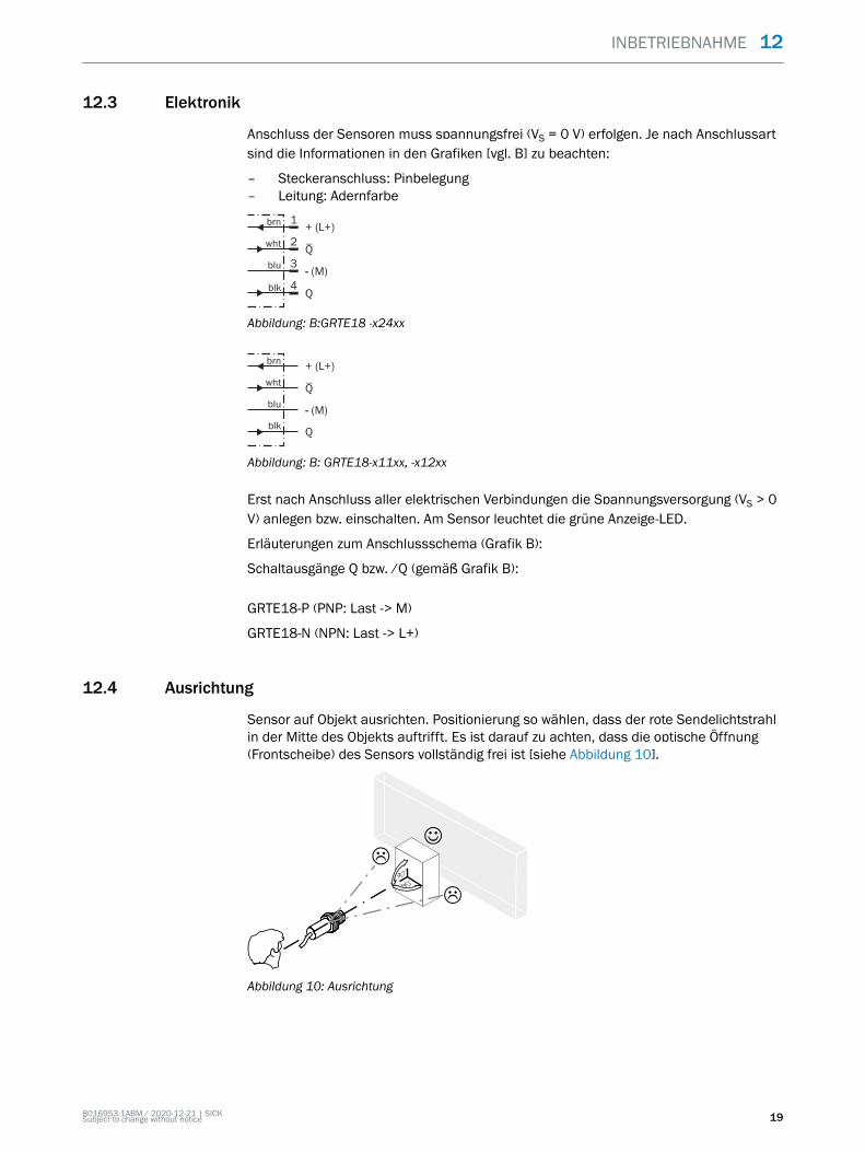
12.3 Elektronik
Anschluss der Sensoren muss spannungsfrei (VS = 0 V) erfolgen. Je nach Anschlussartsind die Informationen in den Grafiken [vgl. B] zu beachten:
– Steckeranschluss: Pinbelegung– Leitung: Adernfarbe
+ (L+)
Q
- (M)
brn
wht
blu
blk
1
2
3
Q4
Abbildung: B:GRTE18 -x24xx
+ (L+)
Q
- (M)
brn
wht
blu
Qblk
Abbildung: B: GRTE18-x11xx, -x12xx
Erst nach Anschluss aller elektrischen Verbindungen die Spannungsversorgung (VS > 0V) anlegen bzw. einschalten. Am Sensor leuchtet die grüne Anzeige-LED.
Erläuterungen zum Anschlussschema (Grafik B):
Schaltausgänge Q bzw. /Q (gemäß Grafik B):
GRTE18-P (PNP: Last -> M)
GRTE18-N (NPN: Last -> L+)
12.4 Ausrichtung
Sensor auf Objekt ausrichten. Positionierung so wählen, dass der rote Sendelichtstrahlin der Mitte des Objekts auftrifft. Es ist darauf zu achten, dass die optische Öffnung(Frontscheibe) des Sensors vollständig frei ist [siehe Abbildung 10].
Abbildung 10: Ausrichtung
INBETRIEBNAHME 12
8016953.1ABM / 2020-12-21 | SICKSubject to change without notice 19

12.5 Einstellung
y x
Abbildung: F
Sensor mit Potentiometer:
Mit dem Potentiometer (Art: 270°) wird die Empfindlichkeit (Schaltabstand) eingestellt.Drehung nach rechts: Erhöhung der Empfindlichkeit (Schaltabstand), Drehung nachlinks: Verringerung der Empfindlichkeit (Schaltabstand). Wir empfehlen, den Schaltab‐stand in das Objekt zu legen, z. B. siehe Grafik F. Nachdem die Empfindlichkeit ein‐gestellt worden ist, das Objekt aus dem Strahlengang entfernen. Der Schaltausgangändert sich (siehe Grafik C).
Sensor ist eingestellt und betriebsbereit. Zur Überprüfung der Funktion Grafik C und Gheranziehen. Verhält sich der Schaltausgang nicht gemäß Grafik C, Einsatzbedingungenprüfen. Siehe Abschnitt Fehlerdiagnose.
Q
(PNP)
(NPN)
Q
q 10
q
10
10
10
Abbildung: C
12 INBETRIEBNAHME
20 8016953.1ABM / 2020-12-21 | SICKSubject to change without notice

Abbildung: G
13 Störungsbehebung
Tabelle Störungsbehebung zeigt, welche Maßnahmen durchzuführen sind, wenn dieFunktion des Sensors nicht mehr gegeben ist.
Tabelle Fehlerdiagnose
Anzeige-LED / Fehlerbild Ursache Maßnahme
grüne LED leuchtet nicht keine Spannung oder Span‐nung unterhalb der Grenz‐werte
Spannungsversorgung prüfen,den gesamten elektrischenAnschluss prüfen (Leitungenund Steckerverbindungen)
grüne LED leuchtet nicht Spannungsunterbrechungen Sicherstellen einer stabilenSpannungsversorgung ohneUnterbrechungen
grüne LED leuchtet nicht Sensor ist defekt Wenn Spannungsversorgungin Ordnung ist, dann Sensoraustauschen
gelbe LED blinkt Sensor ist noch betriebsbe‐reit, aber die Betriebsbedin‐gungen sind nicht optimal
Betriebsbedingungen prüfen:Lichtstrahl (Lichtfleck) voll‐ständig auf das Objekt aus‐richten / Reinigung der opti‐schen Flächen / Empfindlich‐keit (Potentiometer) neu ein‐stellen / Schaltabstand über‐prüfen und ggf. anpassen,siehe „Einsatzbedingungenprüfen“, Seite 16.
gelbe LED leuchtet, kein Objektim Strahlengang
Remissionsvermögen des Hin‐tergrundes zu hoch
Veränderungen des Hinter‐grundes prüfen. Empfindlich‐keit des Sensors reduzierenoder Taster mit Hintergrund‐ausblendung verwenden
Objekt ist im Strahlengang,gelbe LED leuchtet nicht
Empfindlichkeit ist zu geringeingestellt oder Abstand zwi‐schen Sensor und Objekt istzu groß
Schaltabstand vergrößern,Abstand zwischen Sensor undHintergrund beachten
INBETRIEBNAHME 12
8016953.1ABM / 2020-12-21 | SICKSubject to change without notice 21
Anzeige-LED / Fehlerbild Ursache Maßnahme
Objekt ist im Strahlengang,gelbe LED leuchtet nicht
Remissionsvermögen desObjektes ist zu gering
Schaltabstand vergrößern,Abstand zwischen Sensor undHintergrund beachten
14 Demontage und Entsorgung
Die Lichtschranke muss entsprechend den geltenden länderspezifischen Vorschriftenentsorgt werden. Bei der Entsorgung sollte eine werkstoffliche Verwertung (insbeson‐dere der Edelmetalle) angestrebt werden.
HINWEISEntsorgung von Batterien, Elektro- und Elektronikgeräten• Gemäß den internationalen Vorschriften dürfen Batterien, Akkus sowie Elektro-
und Elektronikgeräte nicht mit dem Hausmüll entsorgt werden.• Der Besitzer ist gesetzlich verpflichtet, diese Geräte am Ende ihrer Lebensdauer
bei den entsprechenden öffentlichen Sammelstellen abzugeben.•
WEEE: Dieses Symbol auf dem Produkt, dessen Verpackung oder imvorliegenden Dokument gibt an, dass ein Produkt den genannten Vorschriftenunterliegt.
15 Wartung
SICK-Sensoren sind wartungsfrei.
Wir empfehlen, in regelmäßigen Abständen
• die optischen Grenzflächen zu reinigen• Verschraubungen und Steckverbindungen zu überprüfen
Veränderungen an Geräten dürfen nicht vorgenommen werden.
Irrtümer und Änderungen vorbehalten. Angegebene Produkteigenschaften und techni‐sche Daten stellen keine Garantieerklärung dar.
16 Technische Daten
GRTE18-xxx1x GRTE18-xxx4x GRTE18-xxx6x
Empfohlener Schaltabstand für beste Performance 5 ... 100 mm 10 ... 400 mm 10 ... 800 mm
Schaltabstand max. 3 ... 115 mm1) 5 ... 550 mm 5 ... 1,000 mm
Lichtfleckdurchmesser/Entfernung 8 mm / 100 mm 9 mm / 400 mm 45 mm / 800 mm
Versorgungsspannung UB DC 10 ... 30 V2) DC 10 ... 30 V2) DC 10 ... 30 V2)
Restwelligkeit
Ausgangsstrom Imax. 100 mA 100 mA 100 mA
Stromaufnahme
Schaltfrequenz 500 / s3) 500 / s3) 500 / s3)
Ansprechzeit max. < 1 ms4) < 1 ms4) < 1 ms4)
Schutzart IP67 IP67 IP67
Schutzklasse III5) III5) III5)
14 DEMONTAGE UND ENTSORGUNG
22 8016953.1ABM / 2020-12-21 | SICKSubject to change without notice
GRTE18-xxx1x GRTE18-xxx4x GRTE18-xxx6x
Schutzschaltungen A, B, D6) A, B, D6) A, B, D6)
Betriebsumgebungstemperatur -25 °C ... +55 °C -25 °C ... +55 °C -25 °C ... +55 °C
1) Tastgut mit 90 % Remission (bezogen auf Standard-Weiß DIN 5033)2) Grenzwerte. UB-Anschlüsse verpolsicher. Restwelligkeit max. 5 Vss3) Mit Hell- / Dunkelverhältnis 1:14) Signallaufzeit bei ohmscher Last5) Bemessungsspannung DC 50 V6) A = UB-Anschlüsse verpolsicher
B = Ein- und Ausgänge verpolsicherD = Ausgänge überstrom- und kurzschlussfest
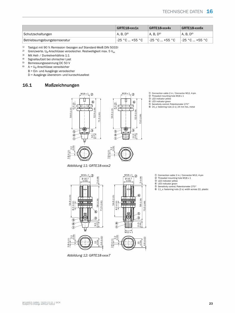
16.1 Maßzeichnungen
Abbildung 11: GRTE18-xxxx2
Abbildung 12: GRTE18-xxxx7
TECHNISCHE DATEN 16
8016953.1ABM / 2020-12-21 | SICKSubject to change without notice 23

N O T I C E D ’ I N S T R U C T I O N
GRTE18
Capteurs photoélectriques cylindriques
de
en
es
fr
it
ja
pt
ru
zh

Produit décrit
GR18
GRTE18
Fabricant
SICK AGErwin-Sick-Straße 179183 WaldkirchAllemagne
Site de fabrication
Remarques juridiques
Cet ouvrage est protégé par les droits d'auteur. Les droits établis restent dévolus àla société SICK AG. La reproduction de l'ouvrage, même partielle, n'est autorisée quedans le cadre légal prévu par la loi sur les droits d'auteur. Toute modification, toutabrègement ou toute traduction de l'ouvrage est interdit sans l'accord écrit exprès de lasociété SICK AG.
Les marques citées dans ce document sont la propriété de leurs détenteurs respectifs.
© SICK AG. Tous droits réservés.
Document original
Ce document est un document original de SICK AG.
2006/42/EC
NO
SAFETY
8016953.1ABM / 2020-12-21 | SICKSubject to change without notice 25

Contenu
17 Consignes générales de sécurité.................................................... 27
18 Remarques sur l’homologation UL................................................. 27
19 Utilisation conforme.......................................................................... 27
20 Mise en service.................................................................................. 2720.1 Vérification des conditions d'utilisation.................................................. 2720.2 Montage.................................................................................................... 2920.3 Électronique.............................................................................................. 3020.4 Alignement................................................................................................ 3020.5 Réglage...................................................................................................... 31
21 Élimination des défauts................................................................... 32
22 Démontage et mise au rebut.......................................................... 33
23 Maintenance...................................................................................... 33
24 Caractéristiques techniques............................................................ 3324.1 Plans cotés................................................................................................ 34
CONTENU
26 8016953.1ABM / 2020-12-21 | SICKSubject to change without notice

17 Consignes générales de sécurité
■ Lire la notice d’instruction avant la mise en service.■
Le raccordement, le montage et la configuration ne doivent être réalisésque par un personnel qualifié.
■2006/42/EC
NO
SAFETY N’est pas un composant de sécurité selon la Directive machines de l’UE.■
N’installez pas le capteur à des endroits directement exposées aux rayonsdu soleil ou à d’autres conditions météorologiques, sauf si cela est explicitementautorisé dans la notice d'instruction.
■ Cette notice d’instruction contient des informations nécessaires durant le cycle devie du capteur.
18 Remarques sur l’homologation UL
UL : utilisation uniquement dans des applications selon la NFPA 79. Ces appareilsdoivent être protégés par un fusible de 1 A adapté à du 30 V C.C.
Des adaptateurs listés UL avec câbles de connexion sont disponibles.
Enclosure type 1.
19 Utilisation conforme
GRTE18 est un détecteur à réflexion directe optoélectronique (appelé capteur dansce document) qui permet la détection optique sans contact d'objets, d'animaux et depersonnes. Toute autre utilisation ou modification du produit annule la garantie deSICK AG.
Détecteur énergétique à réflexion directe
20 Mise en service
20.1 Vérification des conditions d'utilisation
Vérifier les conditions d'utilisation : comparer la portée et les caractéristiques de réflec‐tivité de l'objet à l'aide du diagramme [E] correspondant. (x = portée, y = réserve defonctionnement).Ce faisant, il n'est possible de détecter un objet devant un arrière-plan que si lescaractéristiques de réflectivité de l'objet sont largement supérieures à celles del'arrière-plan en question ou si la distance entre l'objet et l'arrière-plan est suffisante.
CONSIGNES GÉNÉRALES DE SÉCURITÉ 17
8016953.1ABM / 2020-12-21 | SICKSubject to change without notice 27

1
mm(inch)
20(0.79)
40(1.57)
60(2.36)
80(3.15)
100(3.94)
120(4.72)
140(5.51)
100
10
Operating reserve
Distance in mm (inch)
1 2 3
Illustration 13: H: Sensing range 115 mm
1mm
(inch)100
(3.94)200
(7.87)300
(11.81)400
(15.75)500
(19.69)600
(23.62)
100
10
Operating reserve
Distance in mm (inch)
1 2 3
Illustration 14: H: Sensing range 550 mm
20 MISE EN SERVICE
28 8016953.1ABM / 2020-12-21 | SICKSubject to change without notice

0 200(7.87)
400(15.75)
600(23.62)
800(31.5)
1,000(39.37)
100
10
1
Operating reserve
Distance in mm (inch)
2
1
3
Illustration 15: H: Sensing range 800 mm
20.2 Montage
Monter le capteur sur une équerre de fixation adaptée (voir la gamme d'accessoiresSICK).
Respecter le couple de serrage maximal admissible du capteur de 2,0 Nm pour métal /0,9 Nm pour plastique [voir K].
Illustration: K: GRTE18-x24x7
Illustration: K: GRTE18-x24x2
MISE EN SERVICE 20
8016953.1ABM / 2020-12-21 | SICKSubject to change without notice 29

20.3 Électronique
Le raccordement des capteurs doit s'effectuer hors tension (VS = 0 V). Selon le modede raccordement, respecter les informations contenues dans les schémas [B] :
– Raccordement du connecteur : affectation des broches– Câble : couleur des fils
+ (L+)
Q
- (M)
brn
wht
blu
blk
1
2
3
Q4
Illustration: B: GRTE18-x24xx
+ (L+)
Q
- (M)
brn
wht
blu
Qblk
Illustration: B: GRTE18-x11xx, -x12xx
Après avoir terminé tous les raccordements électriques, enclencher l'alimentation élec‐trique (VS > 0 V). La DEL verte s'allume sur le capteur.
Explications relatives au schéma de raccordement (schéma B) :
Sorties de commutation Q ou /Q (selon le schéma B) :
GRTE18-P (PNP : charge -> M)
GRTE18-N (NPN : charge -> L+)
20.4 Alignement
Aligner le capteur sur l’objet. Choisir la position de sorte que le faisceau lumineux émisrouge touche l’objet en plein centre. S’assurer que l’ouverture optique (vitre frontale) ducapteur est parfaitement dégagée [voir illustration 16].
Illustration 16: Alignement
20 MISE EN SERVICE
30 8016953.1ABM / 2020-12-21 | SICKSubject to change without notice

20.5 Réglage
y x
Illustration: F
Capteur avec potentiomètre :
La sensibilité (portée) se règle avec le potentiomètre (réf. : 270°). Rotation vers ladroite : augmentation de la sensibilité (portée), rotation vers la gauche : réduction dela sensibilité (portée). Nous recommandons de régler la portée sur l'objet, par ex. voirschéma F. Après le réglage de la sensibilité, retirer l'objet de la trajectoire du faisceau.La sortie de commutation bascule (voir schéma C).
Le capteur est réglé et prêt à être utilisé. Pour contrôler le fonctionnement, utiliser lesschémas C et G. Si la sortie de commutation ne se comporte pas comme indiqué sur leschéma C, vérifier les conditions d'utilisation. Voir la section consacrée au diagnostic.
Q
(PNP)
(NPN)
Q
q 10
q
10
10
10
Illustration: C
MISE EN SERVICE 20
8016953.1ABM / 2020-12-21 | SICKSubject to change without notice 31

Illustration: G
21 Élimination des défauts
Le tableau Élimination des défauts présente les mesures à appliquer si le capteur nefonctionne plus.
Tableau Diagnostic
LED d'état / image du défaut Cause Mesure
La LED verte ne s'allume pas Pas de tension ou tensioninférieure aux valeurs limites
Contrôler l'alimentation élec‐trique, contrôler tous les bran‐chements électriques (câbleset connexions)
La LED verte ne s'allume pas Coupures d'alimentation élec‐trique
S'assurer que l'alimentationélectrique est stable et ininter‐rompue
La LED verte ne s'allume pas Le capteur est défectueux Si l'alimentation électrique esten bon état, remplacer le cap‐teur
La LED jaune clignote Le capteur est encoreopérationnel, mais les condi‐tions d'utilisation ne sont pasidéales
Vérifier les conditions d'utili‐sation : Diriger le faisceaulumineux (spot lumineux)entièrement sur l'objet /Nettoyage des surfacesoptiques / Régler à nouveaula sensibilité (potentiomètre) /contrôler la distance de com‐mutation et éventuellementl’adapter, voir „Vérificationdes conditions d'utilisation“,page 27.
La LED jaune s'allume, pasd'objet dans la trajectoire dufaisceau
Rémission d’arrière-planexcessive
Contrôler les variations del'arrière-plan Diminuer la sen‐sibilité du capteur ou utili‐ser un capteur à éliminationd'arrière-plan
L'objet est dans la trajectoiredu faisceau, la LED jaune nes'allume pas
La sensibilité est trop faibleou la distance entre le capteuret l'objet est trop grande
Augmenter la portée, tenircompte de la distance entre lecapteur et l'arrière-plan
20 MISE EN SERVICE
32 8016953.1ABM / 2020-12-21 | SICKSubject to change without notice
LED d'état / image du défaut Cause Mesure
L'objet est dans la trajectoiredu faisceau, la LED jaune nes'allume pas
Le pouvoir réfléchissant del'arrière-plan est trop faible
Augmenter la portée, tenircompte de la distance entre lecapteur et l'arrière-plan
22 Démontage et mise au rebut
Le capteur doit être mis au rebut selon les régulations spécifiques au pays respectif.Dans la limite du possible, les matériaux du capteur doivent être recyclés (notammentles métaux précieux).
REMARQUEMise au rebut des batteries, des appareils électriques et électroniques• Selon les directives internationales, les batteries, accumulateurs et appareils
électriques et électroniques ne doivent pas être mis au rebut avec les orduresménagères.
• Le propriétaire est obligé par la loi de retourner ces appareils à la fin de leur cyclede vie au point de collecte respectif.
•
WEEE: Ce symbole sur le produit, son emballage ou dans ce documentindique qu’un produit est soumis à ces régulations.
23 Maintenance
Les capteurs SICK ne nécessitent aucune maintenance.
Nous vous recommandons de procéder régulièrement
• au nettoyage des surfaces optiques• au contrôle des vissages et des connexions enfichables
Ne procéder à aucune modification sur les appareils.
Sujet à modification sans préavis. Les caractéristiques du produit et techniques four‐nies ne sont pas une déclaration de garantie.
24 Caractéristiques techniques
GRTE18-xxx1x GRTE18-xxx4x GRTE18-xxx6x
Distance de commutation conseillée pour la meilleure per‐formance
5 ... 100 mm 10 ... 400 mm 10 ... 800 mm
Portée max. 3 ... 115 mm1) 5 ... 550 mm 5 ... 1,000 mm
Diamètre spot / distance 8 mm / 100 mm 9 mm / 400 mm 45 mm / 800 mm
Tension d'alimentation UB DC 10 ... 30 V2) DC 10 ... 30 V2) DC 10 ... 30 V2)
Ondulation résiduelle
Courant de sortie Imax. 100 mA 100 mA 100 mA
Consommation électrique
Fréquence de commutation 500 / s3) 500 / s3) 500 / s3)
Temps de réponse max. < 1 ms4) < 1 ms4) < 1 ms4)
Indice de protection IP67 IP67 IP67
DÉMONTAGE ET MISE AU REBUT 22
8016953.1ABM / 2020-12-21 | SICKSubject to change without notice 33

GRTE18-xxx1x GRTE18-xxx4x GRTE18-xxx6x
Classe de protection III5) III5) III5)
Protections électriques A, B, D6) A, B, D6) A, B, D6)
Température de service -25 °C ... +55 °C -25 °C ... +55 °C -25 °C ... +55 °C
1) Objet avec 90 % de réémission (par rapport au blanc standard selon DIN 5033)2) Valeurs limites. Connexions UB protégées contre l’inversion de polarité Ondulation résiduelle max. 5 Vss3) Pour un rapport clair/sombre de 1:14) Temps de propagation du signal sur charge ohmique5) Tension de mesure 50 V CC6) A = raccordements UB protégés contre les inversions de polarité
B = entrées et sorties protégées contre les inversions de polaritéD = sorties protégées contre les courts-circuits et les surcharges
24.1 Plans cotés
Illustration 17: GRTE18-xxxx2
Illustration 18: GRTE18-xxxx7
24 CARACTÉRISTIQUES TECHNIQUES
34 8016953.1ABM / 2020-12-21 | SICKSubject to change without notice

M A N U A L D E I N S T R U Ç Õ E S
GRTE18
Barreira de luz cilíndrica
de
en
es
fr
it
ja
pt
ru
zh

Produto descrito
GR18
GRTE18
Fabricante
SICK AGErwin-Sick-Str. 179183 WaldkirchAlemanha
Local de fabricação
Notas legais
Reservados os direitos autorais do presente documento. Todos os direitos permane‐cem em propriedade da empresa SICK AG. A reprodução total ou parcial desta obra sóé permitida dentro dos limites regulamentados pela Lei de Direitos Autorais. É proibidoalterar, resumir ou traduzir esta obra sem a autorização expressa e por escrito da SICKAG.
As marcas citadas neste documento são de propriedade de seus respectivos pro‐prietários.
© SICK AG. Todos os direitos reservados
Documento original
Este é um documento original da SICK AG.
2006/42/EC
NO
SAFETY
36 8016953.1ABM / 2020-12-21 | SICKSubject to change without notice

Índice
25 Instruções gerais de segurança...................................................... 38
26 Indicações sobre a homologação UL............................................. 38
27 Especificações de uso...................................................................... 38
28 Colocação em operação.................................................................. 3828.1 Verificar as condições de uso.................................................................. 3828.2 Montagem................................................................................................. 4028.3 Sistema eletrônico.................................................................................... 4128.4 Alinhamento.............................................................................................. 4128.5 Ajuste......................................................................................................... 42
29 Eliminação de falhas........................................................................ 43
30 Desmontagem e descarte............................................................... 44
31 Manutenção....................................................................................... 44
32 Dados técnicos.................................................................................. 4432.1 Desenhos dimensionais........................................................................... 45
ÍNDICE
8016953.1ABM / 2020-12-21 | SICKSubject to change without notice 37

25 Instruções gerais de segurança
■ Leia o manual de instruções antes de colocar em operação.■
Conexão, montagem e configuração só podem ser realizadas por especia‐listas treinados.
■2006/42/EC
NO
SAFETY Não é um componente de segurança em conformidade com a Diretriz deMáquinas da UE.
■
Não instalar o sensor em locais expostos à luz solar direta ou outrasinfluências atmosféricas, a menos que isto seja expressamente permitido nomanual de operação.
■ Esse manual de instruções contém informações necessárias durante o ciclo devida do sensor.
26 Indicações sobre a homologação UL
UL: Somente na utilização em aplicações de acordo com NFPA 79. Estes dispositivosdevem ser protegidos por um fusível de 1 A adequado para 30 VCC.
Estão disponíveis adaptadores listados pela UL com cabos de conexão.
Enclosure type 1.
27 Especificações de uso
O GRTE18 é um sensor fotoelétrico de proximidade utilizado para a detecçãoóptica, sem contato, de objetos, animais e pessoas. Qualquer utilização diferente oualterações do produto provocam a perda da garantia da SICK AG.
Interruptor fotoelétrico de reflexão energético
28 Colocação em operação
28.1 Verificar as condições de uso
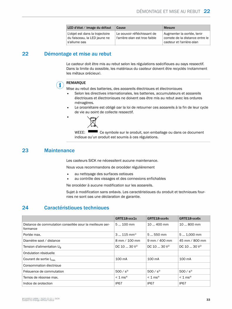
Verificar as condições de uso: equiparar a distância de comutação e a refletividade doobjeto com o respectivo diagrama [cp. H]. (x = distância de comutação, y = reserva defunção).Um objeto só pode ser detectado à frente de um fundo, se a refletividade do objetofor significativamente maior do que a refletividade do fundo ou se a distância entre oobjeto e o fundo for suficientemente grande.
25 INSTRUÇÕES GERAIS DE SEGURANÇA
38 8016953.1ABM / 2020-12-21 | SICKSubject to change without notice
1
mm(inch)
20(0.79)
40(1.57)
60(2.36)
80(3.15)
100(3.94)
120(4.72)
140(5.51)
100
10
Operating reserve
Distance in mm (inch)
1 2 3
Figura 19: H: Sensing range 115 mm
1mm
(inch)100
(3.94)200
(7.87)300
(11.81)400
(15.75)500
(19.69)600
(23.62)
100
10
Operating reserve
Distance in mm (inch)
1 2 3
Figura 20: H: Sensing range 550 mm
COLOCAÇÃO EM OPERAÇÃO 28
8016953.1ABM / 2020-12-21 | SICKSubject to change without notice 39

0 200(7.87)
400(15.75)
600(23.62)
800(31.5)
1,000(39.37)
100
10
1
Operating reserve
Distance in mm (inch)
2
1
3
Figura 21: H: Sensing range 800 mm
28.2 Montagem
Montar o sensor numa cantoneira de fixação adequada (ver linha de acessórios daSICK).
Observar o torque de aperto máximo permitido do sensor de 2,0 Nm para metal / 0,9Nm para plástico [cp. K].
Figura: K: GRTE18-x24x7
Figura: K: GRTE18-x24x2
28 COLOCAÇÃO EM OPERAÇÃO
40 8016953.1ABM / 2020-12-21 | SICKSubject to change without notice

28.3 Sistema eletrônico
A conexão dos sensores deve ser realizada em estado desenergizado (VS = 0 V). Con‐forme o tipo de conexão, devem ser observadas as informações contidas nos gráficos[cp. B]:
– Conector: Pin-out– Cabo: Cor dos fios
+ (L+)
Q
- (M)
brn
wht
blu
blk
1
2
3
Q4
Figura: B: GRTE18-x24xx
+ (L+)
Q
- (M)
brn
wht
blu
Qblk
Figura: B: GRTE18-x11xx, -x12xx
Instalar ou ligar a alimentação de tensão (VS > 0 V) somente após a conclusão detodas as conexões elétricas. O indicador LED verde está aceso no sensor.
Explicações relativas ao esquema de conexões (Gráfico B):
Saídas de comutação Q ou /Q (conforme o gráfico B):
GRTE18-P (PNP: carga -> M)
GRTE18-N (NPN: carga -> L+)
28.4 Alinhamento
Alinhar o sensor ao objeto. Selecionar o posicionamento de forma que o feixe da luz deemissão vermelha incida sobre o centro do objeto. Certificar-se de que a abertura ótica(vidro frontal) do sensor esteja completamente livre [ver figura 22].
Figura 22: Alinhamento
COLOCAÇÃO EM OPERAÇÃO 28
8016953.1ABM / 2020-12-21 | SICKSubject to change without notice 41
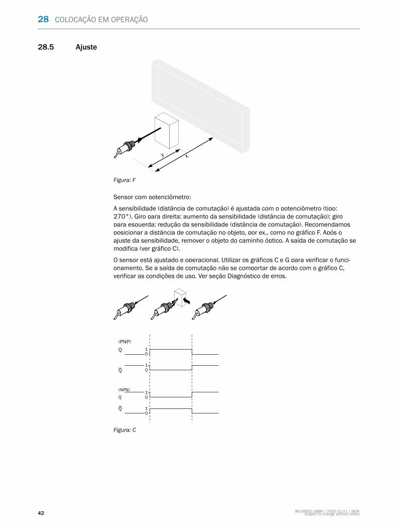
28.5 Ajuste
y x
Figura: F
Sensor com potenciômetro:
A sensibilidade (distância de comutação) é ajustada com o potenciômetro (tipo:270°). Giro para direita: aumento da sensibilidade (distância de comutação); giropara esquerda: redução da sensibilidade (distância de comutação). Recomendamosposicionar a distância de comutação no objeto, por ex., como no gráfico F. Após oajuste da sensibilidade, remover o objeto do caminho óptico. A saída de comutação semodifica (ver gráfico C).
O sensor está ajustado e operacional. Utilizar os gráficos C e G para verificar o funci‐onamento. Se a saída de comutação não se comportar de acordo com o gráfico C,verificar as condições de uso. Ver seção Diagnóstico de erros.
Q
(PNP)
(NPN)
Q
q 10
q
10
10
10
Figura: C
28 COLOCAÇÃO EM OPERAÇÃO
42 8016953.1ABM / 2020-12-21 | SICKSubject to change without notice

Figura: G
29 Eliminação de falhas
A tabela Eliminação de falhas mostra as medidas a serem executadas, quando osensor não estiver funcionando.
Tabela Diagnóstico de erros
Indicador LED / padrão de erro Causa Medida
LED verde apagado Sem tensão ou tensão abaixodos valores-limite
Verificar a alimentação detensão, verificar toda aconexão elétrica (cabos econectores)
LED verde apagado Interrupções de tensão Assegurar uma alimentaçãode tensão estável sem inter‐rupções
LED verde apagado Sensor está com defeito Se a alimentação de tensãoestiver em ordem, substituir osensor
LED amarelo intermitente Sensor ainda está operacio‐nal, mas as condições deoperação não são ideais
Verificar as condições deoperação: Alinhar o feixede luz (ponto de luz) com‐pletamente ao objeto / Lim‐peza das superfícies ópti‐cas / reajustar a sensibilidade(potenciômetro) / Verificare, se necessário, adaptar adistância de comutação, ver„Verificar as condições deuso“, página 38.
LED amarelo aceso, nenhumobjeto no caminho óptico
Remissão do fundo excessiva Verificar as modificações dofundo. Reduzir a sensibilidadedo sensor ou usar o botãocom a supressão de fundo
Objeto está no caminho óptico,LED amarelo apagado
Sensibilidade foi ajustadapara um valor baixo demaisou a distância entre sensor eobjeto é grande demais
Aumentar a distância decomutação, observar adistância entre sensor e fundo
COLOCAÇÃO EM OPERAÇÃO 28
8016953.1ABM / 2020-12-21 | SICKSubject to change without notice 43

Indicador LED / padrão de erro Causa Medida
Objeto está no caminho óptico,LED amarelo apagado
Refletividade do fundo baixademais
Aumentar a distância decomutação, observar adistância entre sensor e fundo
30 Desmontagem e descarte
O sensor deve ser descartado de acordo com os regulamentos específicos por paísaplicáveis. Deve-se realizar um esforço durante o processo de descarte para reciclar osmateriais constituintes (particularmente metais preciosos).
NOTADescarte de pilhas e dispositivos elétricos e eletrônicos• De acordo com diretrizes internacionais, pilhas, acumuladores e dispositivos
elétricos ou eletrônicos não devem ser descartados junto do lixo comum.• O proprietário é obrigado por lei a retornar esses dispositivos ao fim de sua vida
útil para os pontos de coleta públicos respectivos.•
WEEE: Este símbolo sobre o produto, seu pacote o neste documento,indica que um produto está sujeito a esses regulamentos.
31 Manutenção
Os sensores SICK não requerem manutenção.
Recomendamos que se efetue em intervalos regulares
• uma limpeza das superfícies ópticas• uma verificação das conexões roscadas e dos conectores
Não são permitidas modificações no aparelho.
Sujeito a alterações sem aviso prévio. As propriedades do produto e os dados técnicosespecificados não constituem nenhum certificado de garantia.
32 Dados técnicos
GRTE18-xxx1x GRTE18-xxx4x GRTE18-xxx6x
Distância de comutação recomendada para atingir o melhordesempenho
5 ... 100 mm 10 ... 400 mm 10 ... 800 mm
Distância de comutação máx. 3 ... 115 mm1) 5 ... 550 mm 5 ... 1,000 mm
Diâmetro do ponto de luz/distância 8 mm / 100 mm 9 mm / 400 mm 45 mm / 800 mm
Tensão de alimentação UB DC 10 ... 30 V2) DC 10 ... 30 V2) DC 10 ... 30 V2)
Ondulação residual
Corrente de saída Imax. 100 mA 100 mA 100 mA
Consumo de corrente
Frequência de comutação 500 / s3) 500 / s3) 500 / s3)
Tempo máx. de resposta < 1 ms4) < 1 ms4) < 1 ms4)
Tipo de proteção IP67 IP67 IP67
Classe de proteção III5) III5) III5)
30 DESMONTAGEM E DESCARTE
44 8016953.1ABM / 2020-12-21 | SICKSubject to change without notice

GRTE18-xxx1x GRTE18-xxx4x GRTE18-xxx6x
Circuitos de proteção A, B, D6) A, B, D6) A, B, D6)
Temperatura ambiente de funcionamento -25 °C ... +55 °C -25 °C ... +55 °C -25 °C ... +55 °C
1) Objeto a ser detectado com 90% de luminância (com base no padrão branco DIN 5033)2) Valores-limite. Conexões UB protegidas contra inversão de polaridade. Ondulação residual máx. 5 Vss3) Com proporção sombra/luz 1:14) Tempo de funcionamento do sinal com carga ôhmica5) Tensão de dimensionamento CC 50 V6) A = conexões protegidas contra inversão de pólos UB
B = Entradas e saídas protegidas contra polaridade inversaD = Saídas protegidas contra sobrecorrente e curto-circuito
32.1 Desenhos dimensionais
Figura 23: GRTE18-xxxx2
Figura 24: GRTE18-xxxx7
DADOS TÉCNICOS 32
8016953.1ABM / 2020-12-21 | SICKSubject to change without notice 45

I S T R U Z I O N I P E R L ’ U S O
GRTE18
Sensore fotoelettrico cilindrico
de
en
es
fr
it
ja
pt
ru
zh

Descrizione prodotto
GR18
GRTE18
Produttore
SICK AGErwin-Sick-Str. 179183 WaldkirchGermania
Luogo di produzione
Note legali
Questo manuale è protetto dai diritti d'autore. I diritti che ne conseguono rimangonoalla ditta SICK. Il manuale o parti di esso possono essere fotocopiati esclusivamenteentro i limiti previsti dalle disposizioni di legge in materia di diritti d’autore. Non èconsentito modificare, abbreviare o tradurre il presente manuale senza previa autoriz‐zazione scritta della ditta SICK AG.
I marchi riportati nel presente manuale sono di proprietà del rispettivo proprietario.
© SICK AG. Tutti i diritti riservati.
Documento originale
Questo documento è un originale della ditta SICK AG.
2006/42/EC
NO
SAFETY
8016953.1ABM / 2020-12-21 | SICKSubject to change without notice 47

Indice
33 Avvertenze di sicurezza generali..................................................... 49
34 Indicazioni sull’omologazione UL.................................................... 49
35 Uso conforme alle prescrizioni........................................................ 49
36 Messa in funzione............................................................................. 4936.1 Controllare le condizioni d'impiego.......................................................... 4936.2 Montaggio................................................................................................. 5136.3 Elettronica................................................................................................. 5236.4 Orientamento............................................................................................ 5236.5 Regolazione............................................................................................... 53
37 Eliminazione difetti........................................................................... 54
38 Smontaggio e smaltimento............................................................. 55
39 Manutenzione.................................................................................... 55
40 Dati tecnici.......................................................................................... 5540.1 Disegni quotati.......................................................................................... 56
INDICE
48 8016953.1ABM / 2020-12-21 | SICKSubject to change without notice

33 Avvertenze di sicurezza generali
■ Prima di eseguire la messa in servizio, leggere le istruzioni per l’uso.■
Il collegamento, il montaggio e la configurazione devono essere eseguitiesclusivamente da personale tecnico qualificato.
■2006/42/EC
NO
SAFETY Non è un componente di sicurezza ai sensi della Direttiva Macchine UE.■
Non installare il sensore in luoghi esposti all'irraggiamento solare direttoo ad altri influssi meteorologici, se non espressamente consentito nelle istruzioniper l'uso.
■ Le presenti Istruzioni per l’uso contengono informazioni necessarie durante il ciclodi vita del sensore.
34 Indicazioni sull’omologazione UL
UL: Solo per l'utilizzo in applicazioni ai sensi di NFPA 79. Questi dispositivi devonoessere protetti con fusibile 1 A idoneo per 30 V dc.
Sono disponibili adattatori elencati da UL con cavi di collegamento.
Enclosure type 1.
35 Uso conforme alle prescrizioni
La GRTE18 è una fotocellula a riflessione optoelettronica (di seguito nominato sensore)utilizzata per il rilevamento ottico senza contatto di oggetti, animali e persone. Se vieneutilizzata diversamente e in caso di modifiche sul prodotto, decade qualsiasi diritto allagaranzia nei confronti di SICK.
Relè fotoelettrico a riflessione a energia
36 Messa in funzione
36.1 Controllare le condizioni d'impiego
Verificare le condizioni d'impiego: predisporre la distanza di commutazione e il fattore diriflessione dell'oggetto in base al relativo diagramma [cfr. H] . (x = distanza di commuta‐zione, y = riserva di funzionamento).Inoltre la rilevazione di un oggetto da uno sfondo è possibile soltanto qualora il fat‐tore di riflessione dell'oggetto superi nettamente quello dello sfondo o la distanza traoggetto e sfondo sia sufficientemente grande.
AVVERTENZE DI SICUREZZA GENERALI 33
8016953.1ABM / 2020-12-21 | SICKSubject to change without notice 49

1
mm(inch)
20(0.79)
40(1.57)
60(2.36)
80(3.15)
100(3.94)
120(4.72)
140(5.51)
100
10
Operating reserve
Distance in mm (inch)
1 2 3
Figura 25: H: Sensing range 115 mm
1mm
(inch)100
(3.94)200
(7.87)300
(11.81)400
(15.75)500
(19.69)600
(23.62)
100
10
Operating reserve
Distance in mm (inch)
1 2 3
Figura 26: H: Sensing range 550 mm
36 MESSA IN FUNZIONE
50 8016953.1ABM / 2020-12-21 | SICKSubject to change without notice

0 200(7.87)
400(15.75)
600(23.62)
800(31.5)
1,000(39.37)
100
10
1
Operating reserve
Distance in mm (inch)
2
1
3
Figura 27: H: Sensing range 800 mm
36.2 Montaggio
Montare il sensore su un punto di fissaggio adatto (vedi il programma per accessoriSICK).
Rispettare il momento torcente massimo consentito del sensore di 2,0 Nm per ilmetallo / 0,9 Nm per la plastica [cfr. K].
Figura: K: GRTE18-x24x7
Figura: K: GRTE18-x24x2
MESSA IN FUNZIONE 36
8016953.1ABM / 2020-12-21 | SICKSubject to change without notice 51

36.3 Elettronica
Il collegamento dei sensori deve avvenire in assenza di tensione (VS = 0 V). In base altipo di collegamento si devono rispettare le informazioni nei grafici [cfr. B]:
– Collegamento a spina: assegnazione pin– Conduttore: colore filo
+ (L+)
Q
- (M)
brn
wht
blu
blk
1
2
3
Q4
Figura: B: GRTE18-x24xx
+ (L+)
Q
- (M)
brn
wht
blu
Qblk
Figura: B: GRTE18-x11xx, -x12xx
Solamente in seguito alla conclusione di tutti i collegamenti elettrici, ripristinare oaccendere l'alimentazione di tensione (VS > 0 V). Sul sensore si accende l'indicatoreLED verde.
Spiegazioni dello schema di collegamento (grafico B):
Uscite di commutazione Q ovvero /Q (conformemente al grafico B):
GRTE18-P (PNP: carico -> M)
GRTE18-N (NPN: carico -> L+)
36.4 Orientamento
Orientare il sensore sull’oggetto. Scegliere la posizione in modo tale che il raggio di lucerosso emesso colpisca il centro dell’oggetto. Fare attenzione che l’apertura ottica delsensore (frontalino) sia completamente libera [vedi figura 28].
Figura 28: Orientamento
36 MESSA IN FUNZIONE
52 8016953.1ABM / 2020-12-21 | SICKSubject to change without notice

36.5 Regolazione
y x
Figura: F
Sensore con potenziometro:
Con il potenziometro (tipo: 270°) viene regolata la sensibilità (distanza di commuta‐zione). Rotazione verso destra: innalzamento della sensibilità (distanza di commuta‐zione), rotazione verso sinistra: riduzione della sensibilità (distanza di commutazione).Si consiglia di fissare la distanza di commutazione nell'oggetto, ad es. vedi grafico F.Dopo l'impostazione della sensibilità, allontanare l'oggetto dalla traiettoria del raggio.L'uscita di commutazione cambia (vedi grafico C).
Il sensore è impostato e pronto per il funzionamento. Per verificare il funzionamento,osservare i grafici C e G. Se l'uscita di commutazione non si comporta conformementeal grafico C, verificare le condizioni d'impiego. Vedi paragrafo diagnostica delle anoma‐lie.
Q
(PNP)
(NPN)
Q
q 10
q
10
10
10
Figura: C
MESSA IN FUNZIONE 36
8016953.1ABM / 2020-12-21 | SICKSubject to change without notice 53

Figura: G
37 Eliminazione difetti
La tabella di rimozione dei disturbi mostra quali provvedimenti si devono adottarequando il sensore non funziona più.
Tabella diagnostica delle anomalie
Indicatore LED / figura dierrore
Causa Provvedimento
Il LED verde non si accende nessuna tensione o tensioneal di sotto del valore soglia
Verificare la tensione di ali‐mentazione e/o il collega‐mento elettrico
Il LED verde non si accende Interruzioni di tensione Assicurarsi che ci sia un'ali‐mentazione di tensione sta‐bile
Il LED verde non si accende Il sensore è guasto Se l'alimentazione di tensioneè regolare, allora chiedere unasostituzione del sensore
Il LED giallo lampeggia Il sensore è ancora pronto peril funzionamento, ma le con‐dizioni di esercizio non sonoottimali
Controllare le condizioni diesercizio: Dirigere il raggio diluce (il punto luminoso) com‐pletamente sull'oggetto / Puli‐zia delle superfici ottiche /Sensibilità (potenziometro) /Controllare la distanza dilavoro e, se necessario, adat‐tarla, v. „Controllare le condi‐zioni d'impiego“, pagina 49.
il LED giallo si accende, nessunoggetto nella traiettoria del rag‐gio
Remissione dello sfondoeccessiva
Controllare le variazioni dellosfondo. Ridurre la sensibilitàdel sensore oppure utilizzare iltasto con soppressione dellosfondo
L'oggetto è nella traiettoria delraggio, il LED giallo non siaccende
La sensibilità ha un'imposta‐zione troppo bassa o ladistanza tra sensore e oggettoè troppo grande
Aumentare la distanza dicommutazione, rispettare ladistanza tra sensore e sfondo
36 MESSA IN FUNZIONE
54 8016953.1ABM / 2020-12-21 | SICKSubject to change without notice

Indicatore LED / figura dierrore
Causa Provvedimento
L'oggetto è nella traiettoria delraggio, il LED giallo non siaccende
Il fattore di riflessionedell'oggetto è troppo basso
Aumentare la distanza dicommutazione, rispettare ladistanza tra sensore e sfondo
38 Smontaggio e smaltimento
Il sensore deve essere smaltito in conformità con le leggi nazionali vigenti in materia.Durante il processo di smaltimento, riciclare se possibile i materiali che compongono ilsensore (in particolare i metalli nobili).
INDICAZIONESmaltimento di batterie, dispositivi elettrici ed elettronici• In base a direttive internazionali, le batterie, gli accumulatori e i dispositivi elettrici
ed elettronici non devono essere smaltiti tra i rifiuti generici.• Il titolare è tenuto per legge a riconsegnare questi dispositivi alla fine del loro ciclo
di vita presso i rispettivi punti di raccolta pubblici.•
WEEE: Questo simbolo presente sul prodotto, nella sua confezione o nelpresente documento, indica che un prodotto è soggetto a tali regolamentazioni.
39 Manutenzione
I sensori SICK sono esenti da manutenzione.
A intervalli regolari si consiglia di
• pulire le superfici limite ottiche• Verificare i collegamenti a vite e gli innesti a spina
Non è consentito effettuare modifiche agli apparecchi.
Contenuti soggetti a modifiche senza preavviso. Le proprietà del prodotto e le schedetecniche indicate non costituiscono una dichiarazione di garanzia.
40 Dati tecnici
GRTE18-xxx1x GRTE18-xxx4x GRTE18-xxx6x
Distanza di lavoro raccomandata per prestazioni ottimali 5 ... 100 mm 10 ... 400 mm 10 ... 800 mm
Distanza max. di commutazione 3 ... 115 mm1) 5 ... 550 mm 5 ... 1,000 mm
Diametro punto luminoso/distanza 8 mm / 100 mm 9 mm / 400 mm 45 mm / 800 mm
Tensione di alimentazione UB DC 10 ... 30 V2) DC 10 ... 30 V2) DC 10 ... 30 V2)
Ripple residuo
Corrente di uscita Imax. 100 mA 100 mA 100 mA
Consumo di corrente
Frequenza di commutazione 500 / s3) 500 / s3) 500 / s3)
Tempo di reazione max. < 1 ms4) < 1 ms4) < 1 ms4)
Tipo di protezione IP67 IP67 IP67
Classe di protezione III5) III5) III5)
SMONTAGGIO E SMALTIMENTO 38
8016953.1ABM / 2020-12-21 | SICKSubject to change without notice 55

GRTE18-xxx1x GRTE18-xxx4x GRTE18-xxx6x
Commutazioni di protezione A, B, D6) A, B, D6) A, B, D6)
Temperatura ambientale di funzionamento -25 °C ... +55 °C -25 °C ... +55 °C -25 °C ... +55 °C
1) Oggetto con il 90% di remissione (riferito al bianco standard DIN 5033)2) valori limite. Allacciamenti UB protetti dall'inversione di polarità. Valori ripple residuo max. 5 Vss3) Con rapporto chiaro / scuro 1:14) Durata segnale con carico ohmico5) Tensione di misurazione CC 50 V6) A = UV-Allacciamenti protetti dall'inversione di polarità
B = entrate e uscite protette da polarità inversaD = uscite protette da sovracorrente e da cortocircuito.
40.1 Disegni quotati
Figura 29: GRTE18-xxxx2
Figura 30: GRTE18-xxxx7
40 DATI TECNICI
56 8016953.1ABM / 2020-12-21 | SICKSubject to change without notice

I N S T R U C C I O N E S D E U S O
GRTE18
Sensores fotoeléctricos cilíndricos
de
en
es
fr
it
ja
pt
ru
zh

Producto descrito
GR18
GRTE18
Fabricante
SICK AGErwin-Sick-Str. 179183 WaldkirchAlemania
Centro de producción
Información legal
Este documento está protegido por la legislación sobre la propiedad intelectual. Losderechos derivados de ello son propiedad de SICK AG. Únicamente se permite lareproducción total o parcial de este documento dentro de los límites establecidos porlas disposiciones legales sobre propiedad intelectual. Está prohibida la modificación,abreviación o traducción del documento sin la autorización expresa y por escrito deSICK AG.
Las marcas mencionadas en este documento pertenecen a sus respectivos propieta‐rios.
© SICK AG. Reservados todos los derechos.
Documento original
Este es un documento original de SICK AG.
2006/42/EC
NO
SAFETY
58 8016953.1ABM / 2020-12-21 | SICKSubject to change without notice

Índice
41 Indicaciones generales de seguridad............................................. 60
42 Indicaciones sobre la homologación UL........................................ 60
43 Uso conforme a lo previsto.............................................................. 60
44 Puesta en marcha............................................................................. 6044.1 Comprobar las condiciones de aplicación.............................................. 6044.2 Montaje..................................................................................................... 6244.3 Electrónica................................................................................................ 6344.4 Alineación.................................................................................................. 6344.5 Ajuste......................................................................................................... 64
45 Resolución de problemas................................................................ 65
46 Desmontaje y eliminación............................................................... 66
47 Mantenimiento.................................................................................. 66
48 Datos técnicos................................................................................... 6648.1 Dibujos acotados...................................................................................... 67
ÍNDICE
8016953.1ABM / 2020-12-21 | SICKSubject to change without notice 59

41 Indicaciones generales de seguridad
■ Lea las instrucciones de uso antes de realizar la puesta en servicio.■
Únicamente personal especializado y debidamente cualificado debe llevara cabo las tareas de conexión, montaje y configuración.
■2006/42/EC
NO
SAFETY No se trata de un componente de seguridad según las definiciones de ladirectiva de máquinas de la UE.
■
No instale el sensor en lugares directamente expuestos a la radiación solaro a otras influencias climatológicas, salvo si las instrucciones de uso lo permitenexpresamente.
■ Las presentes instrucciones de uso contienen la información necesaria para todala vida útil del sensor.
42 Indicaciones sobre la homologación UL
UL: solo para utilizar en aplicaciones según NFPA 79. Estos dispositivos estarán prote‐gidos por un fusible de 1 A adecuado para 30 VCC.
Se encuentran disponibles adaptadores listados por UL con cable de conexión.
Enclosure type 1.
43 Uso conforme a lo previsto
El GRTE18 es un sensor optoelectrónico de reflexión (en lo sucesivo llamado sensor)empleado para la detección óptica y sin contacto de objetos, animales y personas.Cualquier uso diferente al previsto o modificación en el producto invalidará la garantíapor parte de SICK AG.
Sensor fotoeléctrico de reflexión energético
44 Puesta en marcha
44.1 Comprobar las condiciones de aplicación
Comprobar las condiciones de aplicación: comparar la distancia de conmutación y lacapacidad de remisión del objeto con el diagrama correspondiente [véase fig. H]. (x =distancia de conmutación, y = reserva de funcionamiento.)En este caso, los objetos situados delante de un fondo solo se podrán detectar si lacapacidad de remisión del objeto es considerablemente superior a la del fondo o ladistancia entre el objeto y el fondo es suficientemente grande.
41 INDICACIONES GENERALES DE SEGURIDAD
60 8016953.1ABM / 2020-12-21 | SICKSubject to change without notice

1
mm(inch)
20(0.79)
40(1.57)
60(2.36)
80(3.15)
100(3.94)
120(4.72)
140(5.51)
100
10
Operating reserve
Distance in mm (inch)
1 2 3
Figura 31: H: Sensing range 115 mm
1mm
(inch)100
(3.94)200
(7.87)300
(11.81)400
(15.75)500
(19.69)600
(23.62)
100
10
Operating reserve
Distance in mm (inch)
1 2 3
Figura 32: H: Sensing range 550 mm
PUESTA EN MARCHA 44
8016953.1ABM / 2020-12-21 | SICKSubject to change without notice 61

0 200(7.87)
400(15.75)
600(23.62)
800(31.5)
1,000(39.37)
100
10
1
Operating reserve
Distance in mm (inch)
2
1
3
Figura 33: H: Sensing range 800 mm
44.2 Montaje
Montar el sensor en una escuadra de fijación adecuada (véase el programa de acceso‐rios SICK).
Respetar el par de apriete máximo admisible del sensor de 2,0 Nm para metal y 0,9Nm para plástico [véase K].
Figura: K: GRTE18-x24x7
Figura: K: GRTE18-x24x2
44 PUESTA EN MARCHA
62 8016953.1ABM / 2020-12-21 | SICKSubject to change without notice

44.3 Electrónica
Los sensores deben conectarse sin tensión (VS = 0 V). Debe tenerse en cuenta lainformación de las figuras [B] en función de cada tipo de conexión:
– Conexión de enchufes: asignación de pines– Cable: color del hilo
+ (L+)
Q
- (M)
brn
wht
blu
blk
1
2
3
Q4
Figura: B: GRTE18-x24xx
+ (L+)
Q
- (M)
brn
wht
blu
Qblk
Figura: B: GRTE18-x11xx, -x12xx
No conectar o aplicar la fuente de alimentación (VS > 0 V) hasta que no se hayanrealizado todas las conexiones eléctricas. En el sensor se ilumina el LED indicadorverde.
Explicaciones relativas al esquema de conexión (figura B)
Salidas conmutadas Q o /Q (según figura B):
GRTE18-P (PNP: carga -> M)
GRTE18-N (NPN: carga -> L+)
44.4 Alineación
Alinear el sensor hacia el objeto. Debe seleccionarse una posición que permita que elhaz de luz emitida roja incida en el centro del objeto. Hay que procurar que la aperturaóptica (pantalla frontal) del sensor esté completamente libre [véase figura 34].
Figura 34: Alineación
PUESTA EN MARCHA 44
8016953.1ABM / 2020-12-21 | SICKSubject to change without notice 63

44.5 Ajuste
y x
Figura: F
Sensor con potenciómetro:
Con el potenciómetro (tipo: 270°) se ajusta la sensibilidad (distancia de conmutación).Giro hacia la derecha: aumenta la sensibilidad (distancia de conmutación); giro haciala izquierda: se reduce la sensibilidad (distancia de conmutación). Recomendamosponer la distancia de conmutación en el objeto, p. ej., véase figura F. Una vez ajustadala sensibilidad, retirar el objeto de la trayectoria del haz. La salida conmutada cambia(véase Figura C).
El sensor está ajustado y listo para su uso. Para verificar el funcionamiento, véanse lasfiguras C y G. Si la salida conmutada no se comporta según la figura C, comprobar lascondiciones de aplicación. Véase la sección "Diagnóstico de fallos".
Q
(PNP)
(NPN)
Q
q 10
q
10
10
10
Figura: C
44 PUESTA EN MARCHA
64 8016953.1ABM / 2020-12-21 | SICKSubject to change without notice

Figura: G
45 Resolución de problemas
La tabla “Resolución de problemas” muestra las medidas que hay que tomar cuandoya no está indicado el funcionamiento del sensor.
Tabla Diagnóstico de fallos
LED indicador / imagen deerror
Causa Acción
El LED verde no se ilumina Sin tensión o tensión pordebajo de los valores límite
Comprobar la fuente de ali‐mentación, comprobar toda laconexión eléctrica (cables yconectores)
El LED verde no se ilumina Interrupciones de tensión Asegurar una fuente de ali‐mentación estable sin inte‐rrupciones de tensión
El LED verde no se ilumina El sensor está defectuoso Si la fuente de alimentaciónno tiene problemas, cambiarel sensor
El LED amarillo parpadea El sensor aún está operativo,pero las condiciones de servi‐cio no son óptimas
Comprobar las condicionesde servicio: Alinear el hazde luz (punto de luz) com‐pletamente con el objeto /Limpieza de las superficiesópticas / Reajustar la sensibi‐lidad (potenciómetro) / Com‐probar la distancia de conmu‐tación y corregirla si es nece‐sario, véase „Comprobar lascondiciones de aplicación“,página 60.
El LED amarillo se ilumina, nohay ningún objeto en la trayec‐toria del haz
Reflectancia de fondo exce‐siva
Verificar los cambios delfondo. Reducir la sensibilidaddel sensor o utilizar sensorcon supresión de fondo
El objeto se encuentra en latrayectoria del haz, el LED ama‐rillo no se ilumina
La sensibilidad ajustada esinsuficiente o la distanciaentre el sensor y el objeto esexcesiva
Aumentar la distancia de con‐mutación teniendo en cuentala distancia entre el sensor yel fondo
PUESTA EN MARCHA 44
8016953.1ABM / 2020-12-21 | SICKSubject to change without notice 65

LED indicador / imagen deerror
Causa Acción
El objeto se encuentra en latrayectoria del haz, el LED ama‐rillo no se ilumina
La capacidad de remisión delobjeto es insuficiente
Aumentar la distancia de con‐mutación teniendo en cuentala distancia entre el sensor yel fondo
46 Desmontaje y eliminación
El sensor debe eliminarse de conformidad con las reglamentaciones nacionales aplica‐bles. Como parte del proceso de eliminación, se debe intentar reciclar los materiales almáximo posible (especialmente los metales preciosos).
INDICACIÓNEliminación de las baterías y los dispositivos eléctricos y electrónicos• De acuerdo con las directivas internacionales, las pilas, las baterías y los dispositi‐
vos eléctricos y electrónicos no se deben eliminar junto con la basura doméstica.• La legislación obliga a que estos dispositivos se entreguen en los puntos de
recogida públicos al final de su vida útil.•
WEEE: La presencia de este símbolo en el producto, el material de emba‐laje o este documento indica que el producto está sujeto a esta reglamentación.
47 Mantenimiento
Los sensores SICK no precisan mantenimiento.
A intervalos regulares, recomendamos:
• Limpiar las superficies ópticas externas• Comprobar las uniones roscadas y las conexiones.
No se permite realizar modificaciones en los aparatos.
Sujeto a cambio sin previo aviso. Las propiedades y los datos técnicos del producto nosuponen ninguna declaración de garantía.
48 Datos técnicos
GRTE18-xxx1x GRTE18-xxx4x GRTE18-xxx6x
Distancia de conmutación recomendada para el mejor rendi‐miento
5 ... 100 mm 10 ... 400 mm 10 ... 800 mm
Distancia de conmutación máx. 3 ... 115 mm1) 5 ... 550 mm 5 ... 1,000 mm
Diámetro del punto luminoso/distancia 8 mm / 100 mm 9 mm / 400 mm 45 mm / 800 mm
Tensión de alimentación UB DC 10 ... 30 V2) DC 10 ... 30 V2) DC 10 ... 30 V2)
Ondulación residual
Intensidad de salida Imax. 100 mA 100 mA 100 mA
Consumo de corriente
Frecuencia de conmutación 500 / s3) 500 / s3) 500 / s3)
Tiempo de respuesta máx. < 1 ms4) < 1 ms4) < 1 ms4)
Tipo de protección IP67 IP67 IP67
46 DESMONTAJE Y ELIMINACIÓN
66 8016953.1ABM / 2020-12-21 | SICKSubject to change without notice

GRTE18-xxx1x GRTE18-xxx4x GRTE18-xxx6x
Clase de protección III5) III5) III5)
Circuitos de protección A, B, D6) A, B, D6) A, B, D6)
Temperatura ambiente de servicio -25 °C ... +55 °C -25 °C ... +55 °C -25 °C ... +55 °C
1) Material con un 90% de reflexión (sobre el blanco estándar según DIN 5033)2) Valores límite. Conexiones UB protegidas contra polarización inversa. Ondulación residual máx. 5 Vss3) Con una relación claro/oscuro de 1:14) Duración de la señal con carga óhmica5) Tensión asignada CC 50 V6) A = UB protegidas contra polarización inversa
B = Entradas y salidas protegidas contra polarización incorrectaD=Salidas a prueba de sobrecorriente y cortocircuitos.
48.1 Dibujos acotados
Figura 35: GRTE18-xxxx2
Figura 36: GRTE18-xxxx7
DATOS TÉCNICOS 48
8016953.1ABM / 2020-12-21 | SICKSubject to change without notice 67

操 作 指 南
GRTE18
圆柱形光电传感器
de
en
es
fr
it
ja
pt
ru
zh

所说明的产品
GR18
GRTE18
制造商
SICK AGErwin-Sick-Str.179183 Waldkirch, Germany德国
生产基地
法律信息
本文档受版权保护。其中涉及到的一切权利归西克公司所有。只允许在版权法的范围内复制本文档的全部或部分内容。未经西克公司的明确书面许可,不允许对文档进行修改、删减或翻译。
本文档所提及的商标为其各自所有者的资产。
© 西克公司版权所有。
原始文档
本文档为西克股份公司的原始文档。
2006/42/EC
NO
SAFETY
8016953.1ABM / 2020-12-21 | SICKSubject to change without notice 69

内容
49 一般安全提示......................................................................... 71
50 关于 UL 认证的提示............................................................... 71
51 拟定用途................................................................................ 71
52 调试........................................................................................ 7152.1 检查使用条件.......................................................................................... 7152.2 安装.......................................................................................................... 7352.3 电子元件.................................................................................................. 7452.4 方位.......................................................................................................... 7452.5 设置.......................................................................................................... 75
53 故障排除................................................................................ 76
54 拆卸和废弃处置...................................................................... 76
55 保养........................................................................................ 77
56 技术参数................................................................................ 7756.1 尺寸图...................................................................................................... 78
内容
70 8016953.1ABM / 2020-12-21 | SICKSubject to change without notice

49 一般安全提示
■ 调试之前阅读本操作指南。■
只有经过培训的专业人员才能执行连接、安装和配置工作。■
2006/42/EC
NO
SAFETY 非符合欧盟机械指令的安全组件。■
请勿将传感器安装在阳光直射或受其它气候影响的位置,除非操作指南中明确允许这一行为。
■ 这些操作指南包含传感器寿命周期内所必需的信息。
50 关于 UL 认证的提示
UL:仅限用于符合 NFPA 79 的应用。该设备类型应由一个适用于 30 V 直流电的1 A 保险丝进行保护。
可用 UL 所列出的含连接线缆的连接器。
Enclosure type 1。
51 拟定用途
GRTE18 是一种漫反射式光电传感器(下文简称为传感器”),用于物体、动物和人体的非接触式光学检测如果滥用本产品或擅自更改产品,则 SICK AG 公司所作之质保承诺均将失效。
能量型光电传感器
52 调试
52.1 检查使用条件
检查使用条件:使用随附的图表 [参照 H] 调整开关距离和物体的反射能力。(x =开关距离,y = 信号冗余)。仅当物体的反射能力明显大于背景的反射能力或物体和背景之间的间距足够大时,才能检测到位于背景前的物体。
一般安全提示 49
8016953.1ABM / 2020-12-21 | SICKSubject to change without notice 71

1
mm(inch)
20(0.79)
40(1.57)
60(2.36)
80(3.15)
100(3.94)
120(4.72)
140(5.51)
100
10
Operating reserve
Distance in mm (inch)
1 2 3
插图 37: H: Sensing range 115 mm
1mm
(inch)100
(3.94)200
(7.87)300
(11.81)400
(15.75)500
(19.69)600
(23.62)
100
10
Operating reserve
Distance in mm (inch)
1 2 3
插图 38: H: Sensing range 550 mm
52 调试
72 8016953.1ABM / 2020-12-21 | SICKSubject to change without notice

0 200(7.87)
400(15.75)
600(23.62)
800(31.5)
1,000(39.37)
100
10
1
Operating reserve
Distance in mm (inch)
2
1
3
插图 39: H: Sensing range 800 mm
52.2 安装
将传感器安装在合适的安装托架上(参见 SICK 附件说明书)。
传感器金属部件的拧紧扭矩为 2.0 NM,塑料部件的拧紧扭矩为 0.9 NM [根据 K]。
插图: K: GRTE18-x24x7
插图: K: GRTE18-x24x2
调试 52
8016953.1ABM / 2020-12-21 | SICKSubject to change without notice 73

52.3 电子元件
必须在无电压状态 (VS = 0 V) 连接传感器。依据不同连接类型,注意图 [参照 B] 中的信息:
– 插头连接:引线分配– 导线:芯线颜色
+ (L+)
Q
- (M)
brn
wht
blu
blk
1
2
3
Q4
插图: B: GRTE18-x24xx
+ (L+)
Q
- (M)
brn
wht
blu
Qblk
插图: B: GRTE18-x11xx, -x12xx
完成所有电子连接后,才敷设或接通电源 (VS > 0 V)。传感器上的绿色 LED 指示灯亮起。
接线图(图 B)说明:
开关输出端 Q 或 /Q(根据图 B):
GRTE18-P(PNP:负载 -> M)
GRTE18-N(NPN:负载 -> L+)
52.4 方位
将传感器对准物体。选择定位,确保红色发射光束射中物体的中间。此时,应注意传感器的光学开口(透明保护盖)处应无任何遮挡 [参见 插图 40]。
插图 40: 方位
52 调试
74 8016953.1ABM / 2020-12-21 | SICKSubject to change without notice

52.5 设置
y x
插图: F
配电位计的传感器:
使用电位计(型号:270°) 设置灵敏度(开关距离)。向右旋转:提高灵敏度(开关距离),向左旋转:降低灵敏度(开关距离)。我们建议开关距离应涵盖物体;例如,参见图 F。灵敏度设置完成后,将物体从光路中移出。改变输出信号开关装置(参见图 C)。
传感器已设置并准备就绪。参照图 C 和 G 检查功能。如果输出信号开关装置的动作不符合图 C,则须检查使用条件。参见故障诊断章节。
Q
(PNP)
(NPN)
Q
q 10
q
10
10
10
插图: C
调试 52
8016953.1ABM / 2020-12-21 | SICKSubject to change without notice 75

插图: G
53 故障排除
故障排除表格中罗列了传感器无法执行某项功能时应采取的各项措施。
表故障诊断
LED 指示灯 / 故障界面 原因 措施
绿色 LED 未亮起 无电压或电压低于极限值 检查电源,检查整体电气连接(导线和插头连接)
绿色 LED 未亮起 电压中断 确保电源稳定无中断
绿色 LED 未亮起 传感器损坏 如果电源正常,则更换传感器
,黄色 LED 闪烁 尽管传感器准备就绪,但运行条件不佳
检查运行条件: 光束(光斑)完全对准物体 / 清洁光学表面 / 重新设置灵敏度(电位计) / 检查触发感应距离,必要时调整,参见 „检查使用条件“, 第 71 页 。
黄色 LED 亮起,光路中无物体
过度的背景反射 检查背景的变化。降低传感器灵敏度或使用带背景抑制功能的探测器
光路中有物体,黄色 LED 未亮起
灵敏度的设置过低或传感器和物体之间的间距过大
增大开关距离,注意传感器和背景之间的间距
光路中有物体,黄色 LED 未亮起
物体的反射能力过低 增大开关距离,注意传感器和背景之间的间距
54 拆卸和废弃处置
必须根据适用的国家/地区特定法规处理传感器。在废弃处置过程中应努力回收构成材料(特别是贵金属)。
52 调试
76 8016953.1ABM / 2020-12-21 | SICKSubject to change without notice

提示电池、电气和电子设备的废弃处置• 根据国际指令,电池、蓄电池和电气或电子设备不得作为一般废物处理。• 根据法律,所有者有义务在使用寿命结束时将这些设备返还给相应的公共收集
点。•
WEEE: 产品、其包装或本文档中的此符号表示产品受这些法规约束。
55 保养
SICK 传感器无需保养。
我们建议,定期:
• 清洁镜头检测面• 检查螺栓连接和插头连接
不得对设备进行任何改装。
如有更改,不另行通知。所给出的产品特性和技术参数并非质保声明。
56 技术参数
GRTE18-xxx1x GRTE18-xxx4x GRTE18-xxx6x
建议的触发感应距离,以获得最佳性能 5 ... 100 mm 10 ... 400 mm 10 ... 800 mm
最大开关距离 3 ... 115 mm1) 5 ... 550 mm 5 ... 1,000 mm
光斑直径/距离 8 mm / 100 mm 9 mm / 400 mm 45 mm / 800 mm
供电电压 UB DC 10 ... 30 V2) DC 10 ... 30 V2) DC 10 ... 30 V2)
残余纹波
输出电流 Imax. 100 mA 100 mA 100 mA
消耗电流
开关频率 500 / s3) 500 / s3) 500 / s3)
最长响应时间 < 1 ms4) < 1 ms4) < 1 ms4)
防护类型 IP67 IP67 IP67
防护等级 III5) III5) III5)
保护电路 A, B, D6) A, B, D6) A, B, D6)
工作环境温度 -25 °C ... +55 °C -25 °C ... +55 °C -25 °C ... +55 °C
1) 具有 90 % 反射比的扫描对象(指 DIN 5033 规定的标准白)2) 极限值。UB 接口,带反极性保护。残余纹波,最大 5 VSS3) 明暗比为 1:14) 信号传输时间(电阻负载时)5) 测量电压 DC 50 V6) A = UB 接口(已采取反极性保护措施)
B = 具有反极性保护的输入端和输出端D = 抗过载电流和抗短路输出端
保养 55
8016953.1ABM / 2020-12-21 | SICKSubject to change without notice 77

56.1 尺寸图
插图 41: GRTE18-xxxx2
插图 42: GRTE18-xxxx7
56 技术参数
78 8016953.1ABM / 2020-12-21 | SICKSubject to change without notice

取 扱 説 明 書
GRTE18
シリンダ型光電センサ
de
en
es
fr
it
ja
pt
ru
zh

説明されている製品GR18GRTE18
メーカーSICK AGErwin-Sick-Str.179183 WaldkirchGermany
生産拠点
法律情報本書は著作権によって保護されています。著作権に由来するいかなる権利も SICKAG が保有しています。本書および本書の一部の複製は、著作権法の法的規定の範囲内でのみ許可されます。本書の内容を変更、削除または翻訳することは、SICKAG の書面による明確な同意がない限り禁じられています。本書に記載されている商標は、それぞれの所有者の所有です。© SICK AG. 無断複写・複製・転載を禁ず。
オリジナルドキュメントこのドキュメントは SICK AG のオリジナルドキュメントです。
2006/42/EC
NO
SAFETY
80 8016953.1ABM / 2020-12-21 | SICKSubject to change without notice

目次57 一般的な安全上の注意事項.................................................... 82
58 UL 認証に関する注意事項..................................................... 82
59 正しいご使用方法.................................................................. 82
60 コミッショニング.................................................................. 8260.1 使用条件を確認してください.............................................................. 8260.2 取付け...................................................................................................... 8460.3 エレクトロニクス.................................................................................. 8560.4 方向調整.................................................................................................. 8560.5 設定.......................................................................................................... 86
61 トラブルシューティング....................................................... 87
62 分解および廃棄...................................................................... 88
63 メンテナンス......................................................................... 88
64 技術仕様................................................................................ 8864.1 寸法図...................................................................................................... 89
目次
8016953.1ABM / 2020-12-21 | SICKSubject to change without notice 81

57 一般的な安全上の注意事項■ コミッショニング前に取扱説明書をよくお読みください。■
本製品の接続・取付・コンフィグレーションは、訓練を受けた技術者が行ってください。
■2006/42/EC
NO
SAFETY 本製品は、EU の機械指令を満たす人体保護用の安全コンポーネントではありません。
■
取扱説明書で明示的に許可されている場合を除き、直射日光やその他の天候の影響を受ける場所には設置しないでください。
■ 本取扱説明書には、センサのライフサイクル中に必要となる情報が記載されています。
58 UL 認証に関する注意事項UL:NFPA79 に準拠した用途においてのみご使用ください。この装置は 30V DC用の 1 A ヒューズによって保護されるものとします。UL 規格によってリストアップされた接続ケーブル付きのアダプターを使用できます。Enclosure type 1.
59 正しいご使用方法GRTE18 は反射形光電センサ(以下「センサ」)で、物体、動物または人などを光学的技術により非接触で検知するための装置です。本製品が本来の使用用途以外の目的に使用されたり、何らかの方法で改造された場合、SICK AG に対するいかなる保証要求も無効になります。エネルギー性光電近接センサ
60 コミッショニング60.1 使用条件を確認してください
使用条件に従ってください:対応する図 [H] に従って、検出範囲および対象物の反射率を設定します(x = 検出範囲、y = 動作余裕度)。この際、対象物を背景前で検出することができるのは、対象物の反射率が背景のそれよりも高い場合、または対象物と背景との距離が十分に確保出来ている場合のみです。
57 一般的な安全上の注意事項
82 8016953.1ABM / 2020-12-21 | SICKSubject to change without notice

1
mm(inch)
20(0.79)
40(1.57)
60(2.36)
80(3.15)
100(3.94)
120(4.72)
140(5.51)
100
10
Operating reserve
Distance in mm (inch)
1 2 3
図 43: H: Sensing range 115 mm
1mm
(inch)100
(3.94)200
(7.87)300
(11.81)400
(15.75)500
(19.69)600
(23.62)
100
10
Operating reserve
Distance in mm (inch)
1 2 3
図 44: H: Sensing range 550 mm
コミッショニング 60
8016953.1ABM / 2020-12-21 | SICKSubject to change without notice 83

0 200(7.87)
400(15.75)
600(23.62)
800(31.5)
1,000(39.37)
100
10
1
Operating reserve
Distance in mm (inch)
2
1
3
図 45: H: Sensing range 800 mm
60.2 取付け適切なブラケットを使用してセンサを取り付けます(SICK 付属品カタログを参照)。センサの最大許容締付トルク 2.0 Nm(金属)/0.9 Nm(プラスチック)に注意してください [K]。
図: K: GRTE18-x24x7
図: K: GRTE18-x24x2
60 コミッショニング
84 8016953.1ABM / 2020-12-21 | SICKSubject to change without notice

60.3 エレクトロニクスセンサの接続は必ず無電圧状態(VS = 0 V)で行ってください。接続タイプに応じて、図 [B] の情報に注意する必要があります:– オスコネクタ接続:ピン割り当て– ケーブル:芯の色
+ (L+)
Q
- (M)
brn
wht
blu
blk
1
2
3
Q4
図: B: GRTE18-x24xx
+ (L+)
Q
- (M)
brn
wht
blu
Qblk
図: B: GRTE18-x11xx, -x12xx
まずすべての電気接続を確立してから、電源(VS > 0 V)をオンにしてください。緑色の LED 表示灯がセンサ上で点灯します。接続図の説明(図 B)。スイッチング出力 Q および /Q(図 B に準拠):
GRTE18-P(PNP:負荷 -> M)GRTE18-N(NPN:負荷 -> L+)
60.4 方向調整センサを対象物に合わせて光軸調整します。赤色の投光軸が対象物の中央に照射されるように位置決めします。センサの光開口 (フロントカバー) が全く遮らぎられることがないよう注意してください [図 46 を参照]。
図 46: 方向調整
コミッショニング 60
8016953.1ABM / 2020-12-21 | SICKSubject to change without notice 85

60.5 設定
y x
図: F
ポテンショメータ付きセンサ:ポテンショメータ (タイプ: 270°) で感度 (検出距離) を設定します。右へ回すと感度(検出距離)が増大し、左へ回すと感度(検出距離)が減少します。検出距離を対象物内に入れることをお勧めします。例えばグラフ F を参照してください。感度が設定された後、対象物を光軸から取り除くことができます。スイッチング出力が変化します(グラフ C を参照)。これでセンサは設定され動作準備が整いました。機能を点検するために、グラフ Cおよび G を使用します。スイッチング出力がグラフ C に従った動作を示さない場合は、使用条件を点検してください。故障診断の章を参照。
Q
(PNP)
(NPN)
Q
q 10
q
10
10
10
図: C
60 コミッショニング
86 8016953.1ABM / 2020-12-21 | SICKSubject to change without notice

図: G
61 トラブルシューティングトラブルシューティングの表は、センサが機能しなくなった場合に、どのような対策を講じるべきかを示しています。
表エラー診断LED 表示灯/故障パターン 原因 対策緑色の LED が点灯しない 無電圧、または電圧が限界値
以下電源を確認し、すべての電気接続(ケーブルおよびプラグ接続)を確認します
緑色の LED が点灯しない 電圧がきていない又は不安定
安定した電源電圧が供給されていることを確認します
緑色の LED が点灯しない センサの異常 電源に問題がなければ、センサを交換します
黄色い LED が点滅 センサの動作準備はまだ整っているが、動作条件が最適ではない
動作条件を確認します: 投光光軸(投光スポット)を対象物に完全に合わせます / 光学面の洗浄 / 感度を再調整する(感度調整ボリューム) / 検出距離を点検し、必要に応じて調整する、参照„使用条件を確認してください“, ページ 82。
黄色い LED が点灯、光軸に対象物がない
背景からの過剰な反射 背景の変更を確認してください。センサの感度を下げるか、または BGS 機能付きのセンサを使用してください
対象物は光軸にある、黄色いLED は点灯しない
センサの設定感度が低すぎるか、またはセンサと対象物との距離が長すぎる
センサと背景間の距離に注意して検出距離を拡大します。
対象物は光軸にある、黄色いLED は点灯しない
検出対象物の反射率が不十分
センサと背景間の距離に注意して検出距離を拡大します。
コミッショニング 60
8016953.1ABM / 2020-12-21 | SICKSubject to change without notice 87

62 分解および廃棄センサは必ず該当国の規制にしたがって処分してください。廃棄処理の際には、できるだけ構成材料をリサイクルするよう努めてください(特に貴金属類)。
メモバッテリー、電気および電子デバイスの廃棄• 国際的指令に従い、バッテリー、アキュムレータ、および電気または電子デバ
イスは、一般廃棄物として廃棄することはできません。• 法律により、所有者は、本デバイスの耐用年数の終了時に本デバイスをそれぞ
れの公的な回収場所まで返却することが義務付けられています。•
WEEE: 製品、梱包または本文書に記載されているこの記号は、製品がこれらの規制の対象であることを示します。
63 メンテナンスSICK センサはメンテナンスフリーです。定期的に以下を行うことをお勧めしています:• レンズ境界面の清掃• ネジ締結と差込み締結の点検機器を改造することは禁止されています。記載内容につきましては予告なしに変更する場合がございますのであらかじめご了承ください。指定された製品特性および技術データは保証書ではありません。
64 技術仕様GRTE18-xxx1x GRTE18-xxx4x GRTE18-xxx6x
最高性能を発揮できる推奨検出距離 5 ... 100 mm 10 ... 400 mm 10 ... 800 mm最大検出範囲 3 ... 115 mm1) 5 ... 550 mm 5 ... 1,000 mm光点のスポット径/距離 8 mm / 100 mm 9 mm / 400 mm 45 mm / 800 mm供給電圧 UB DC 10 ... 30 V2) DC 10 ... 30 V2) DC 10 ... 30 V2)
残留リップル出力電流 Imax. 100 mA 100 mA 100 mA消費電流スイッチング周波数 500 / s3) 500 / s3) 500 / s3)
最大応答時間 < 1 ms4) < 1 ms4) < 1 ms4)
保護等級 IP67 IP67 IP67保護クラス III5) III5) III5)
回路保護 A, B, D6) A, B, D6) A, B, D6)
62 分解および廃棄
88 8016953.1ABM / 2020-12-21 | SICKSubject to change without notice

GRTE18-xxx1x GRTE18-xxx4x GRTE18-xxx6x周辺温度 (作動中) -25 °C ... +55 °C -25 °C ... +55 °C -25 °C ... +55 °C
1) 反射率 90 % の対象物(DIN 5033 に準拠した白色)2) 限界値。UB 接続 逆極性保護。残留リップル 最大 5 VSS3) ライト/ダークの比率 1:14) 負荷のある信号経過時間5) 定格電圧 DC 50 V6) A = UB 電源電圧逆接保護
B = 出入力 逆接保護D = 出力の過電流保護および短絡保護
64.1 寸法図
図 47: GRTE18-xxxx2
図 48: GRTE18-xxxx7
技術仕様 64
8016953.1ABM / 2020-12-21 | SICKSubject to change without notice 89

Р У К О В О Д С Т В О П О Э К С П Л У А Т А Ц И И
GRTE18
Цилиндрические фотоэлектрические датчики
de
en
es
fr
it
ja
pt
ru
zh

Описание продукта
GR18
GRTE18
Изготовитель
SICK AGErwin-Sick-Str. 179183 WaldkirchDeutschland (Германия)
Место изготовления
Правовые примечания
Данная документация защищена авторским правом. Обоснованные таким образомправа сохраняются за фирмой SICK AG. Тиражирование документации или еечасти допускается только в рамках положений закона об авторских правах.Внесение в документацию изменений, сокращение или перевод ее содержимогобез однозначного письменного согласия фирмы SICK AG запрещено.
Товарные знаки, упомянутые в данном документе, являются собственностьюсоответствующего владельца.
© SICK AG Все права защищены.
Оригинальный документ
Настоящий документ является оригинальным документом SICK AG.
2006/42/EC
NO
SAFETY
8016953.1ABM / 2020-12-21 | SICKSubject to change without notice 91

Содержание
65 Общие указания по технике безопасности................................ 93
66 Указания по допуску к эксплуатации UL..................................... 93
67 Использование по назначению.................................................... 93
68 Ввод в эксплуатацию....................................................................... 9368.1 Проверка условий применения............................................................. 9368.2 Монтаж...................................................................................................... 9568.3 Электроника............................................................................................. 9668.4 Выравнивание......................................................................................... 9668.5 Настройка................................................................................................. 97
69 Устранение неисправностей......................................................... 98
70 Демонтаж и утилизация.................................................................. 99
71 Техобслуживание............................................................................. 99
72 Технические характеристики........................................................ 9972.1 Размерные чертежи................................................................................ 100
СОДЕРЖАНИЕ
92 8016953.1ABM / 2020-12-21 | SICKSubject to change without notice

65 Общие указания по технике безопасности
■ Перед вводом в эксплуатацию прочитайте инструкции по эксплуатации.■
Подключение, монтаж и настройку могут выполнять толькоквалифицированные специалисты.
■2006/42/EC
NO
SAFETY Не является компонентом безопасности в соответствии с Директивой ЕСпо работе с машинным оборудованием.
■
Не устанавливайте датчик в местах, подверженных воздействию прямыхсолнечных лучей или других атмосферных воздействий, за исключениемслучаев, когда это явным образом разрешено в руководстве по эксплуатации.
■ Настоящие инструкции по эксплуатации содержат информацию, необходимую втечение срока эксплуатации датчика.
66 Указания по допуску к эксплуатации UL
UL: Только для использования в областях применения согласно NFPA 79. Этиустройства должны быть защищены предохранителем 1 A, подходящим для 30 Впостоянного тока.
Доступны адаптеры с соединительными кабелями, перечисленные UL.
Enclosure type 1.
67 Использование по назначению
GRTE18 является оптоэлектронным отражательным световым датчиком (вдальнейшем называемым "сенсор") и используется для оптической бесконтактнойрегистрации вещей, животных и людей. При ином использовании и при внесенииизменений в изделие подача любых гарантийных претензий к SICK AG исключена.
Энергетический отражательный световой датчик
68 Ввод в эксплуатацию
68.1 Проверка условий применения
Проверить условия применения: скорректировать дистанцию переключения ияркость объекта с помощью соответствующей диаграммы [см. H]. (x = дистанцияпереключения, y = функциональный резерв).При этом можно детектировать объект на фоне лишь в том случае, если яркостьобъекта существенно выше, чем яркость фона или расстояние между объектом ифоном достаточно велико.
ОБЩИЕ УКАЗАНИЯ ПО ТЕХНИКЕ БЕЗОПАСНОСТИ 65
8016953.1ABM / 2020-12-21 | SICKSubject to change without notice 93

1
mm(inch)
20(0.79)
40(1.57)
60(2.36)
80(3.15)
100(3.94)
120(4.72)
140(5.51)
100
10
Operating reserve
Distance in mm (inch)
1 2 3
Рисунок 49: H: Sensing range 115 mm
1mm
(inch)100
(3.94)200
(7.87)300
(11.81)400
(15.75)500
(19.69)600
(23.62)
100
10
Operating reserve
Distance in mm (inch)
1 2 3
Рисунок 50: H: Sensing range 550 mm
68 ВВОД В ЭКСПЛУАТАЦИЮ
94 8016953.1ABM / 2020-12-21 | SICKSubject to change without notice

0 200(7.87)
400(15.75)
600(23.62)
800(31.5)
1,000(39.37)
100
10
1
Operating reserve
Distance in mm (inch)
2
1
3
Рисунок 51: H: Sensing range 800 mm
68.2 Монтаж
Установите сенсор на подходящем крепежном уголке (см. программупринадлежностей от SICK).
Выдерживайте максимально допустимый момент затяжки сенсора в 2,0 Нм дляметалла / 0,9 Нм для пластмассы [см. K].
Рисунок: K: GRTE18-x24x7
Рисунок: K: GRTE18-x24x2
ВВОД В ЭКСПЛУАТАЦИЮ 68
8016953.1ABM / 2020-12-21 | SICKSubject to change without notice 95

68.3 Электроника
Подключайте сенсоры при отключенном напряжении питания (VS = 0 В). Взависимости от типа подключения следует принять во внимание информацию сграфиков [см. B]:
– Штекерный разъем: назначение контактов– Проводник: цвет жилы
+ (L+)
Q
- (M)
brn
wht
blu
blk
1
2
3
Q4
Рисунок: B: GRTE18-x24xx
+ (L+)
Q
- (M)
brn
wht
blu
Qblk
Рисунок: B: GRTE18-x11xx, -x12xx
Подавайте и включайте напряжение питания только после завершения подключениявсех электрических соединений (VS > 0 В). На сенсоре включается зеленыйсветодиодный индикатор.
Пояснения к схеме электрических соединений (график B):
Коммутирующие выходы Q или /Q (согласно графику B):
GRTE18-P (PNP: нагрузка -> M)
GRTE18-N (NPN: нагрузка -> L+)
68.4 Выравнивание
Направьте датчик на объект. Выберите такую позицию, чтобы красный лучизлучателя попадал в центр объекта. Оптическое отверстие (лицевая панель) надатчике должно быть полностью свободным [см. рисунок 52].
Рисунок 52: Выравнивание
68 ВВОД В ЭКСПЛУАТАЦИЮ
96 8016953.1ABM / 2020-12-21 | SICKSubject to change without notice

68.5 Настройка
y x
Рисунок: F
Сенсор с потенциометром:
С помощью потенциометра (тип: 270°) регулируется чувствительность (расстояниесрабатывания). Вращение вправо: увеличение чувствительности (дистанциипереключения), вращение влево: уменьшение чувствительности (дистанциипереключения). Рекомендуется установить дистанцию срабатывания в объекте,например, см. график F. После регулировки чувствительности удалить объект с путилуча. Состояние коммутирующего выхода изменяется (см. график С).
Сенсор настроен и готов к эксплуатации. Для проверки функционированиявоспользуйтесь графиками C и G. Если характер поведения коммутирующеговыхода не соответствует графику С, проверить условия применения. См. раздел"Диагностика неисправностей".
Q
(PNP)
(NPN)
Q
q 10
q
10
10
10
Рисунок: C
ВВОД В ЭКСПЛУАТАЦИЮ 68
8016953.1ABM / 2020-12-21 | SICKSubject to change without notice 97

Рисунок: G
69 Устранение неисправностей
В таблице Устранение неисправностей показано, какие меры необходимопредпринять, если датчики не работают.
таблице диагностики неисправностей
Cветодиодный индикатор /картина неисправности
Причина Меры по устранению
зеленый светодиод не горит нет напряжения питанияили оно ниже нижнегопредельного значения
Проверить напряженияпитания, всюсхему электроподключения(проводку и разъемныесоединения)
зеленый светодиод не горит Пропадание напряженияпитания
Обеспечить надежную подачунапряжения питания без егопропадания
зеленый светодиод не горит Сенсор неисправен Если напряжение питания впорядке, то заменить сенсор
желтый светодиод мигает Сенсор пока еще готов кработе, но эксплуатационныеусловия не оптимальны
Проверка эксплуатационныхусловий: Полностьюсориентировать световойлуч (световое пятно) наобъект / чистка оптическихповерхностей /зановонастроить чувствительность(потенциометром) /проверить ипри необходимостискорректировать расстояниесрабатывания, см.„Проверка условийприменения“, страница 93.
желтый светодиод горит,объект на пути лучаотсутствует
Очень сильноеослаблениефона
Проверить изменения фона.Уменьшить чувствительностьсенсора или использоватьдатчик с подавлениемзаднего фона.
68 ВВОД В ЭКСПЛУАТАЦИЮ
98 8016953.1ABM / 2020-12-21 | SICKSubject to change without notice

Cветодиодный индикатор /картина неисправности
Причина Меры по устранению
Объект на пути луча, желтыйсветодиод не горит
Установлена слишкоммалая чувствительность илирасстояние между сенсороми объектом слишком велико
Увеличить расстояниесрабатывания, соблюдатьрасстояние между сенсороми фоном
Объект на пути луча, желтыйсветодиод не горит
Характеристика яркостиобъекта слишком мала
Увеличить расстояниесрабатывания, соблюдатьрасстояние между сенсороми фоном
70 Демонтаж и утилизация
Датчик должен быть утилизирован в соответствии с действующим законодательствомконкретной страны. В процессе утилизации следует прилагать усилия дляпереработки составляющих материалов (особенно драгоценных металлов).
УКАЗАНИЕУтилизация батарей, электрических и электронных устройств• В соответствии с международными директивами батареи, аккумуляторы и
электрические или электронные устройства не должны выбрасываться в общиймусор.
• По закону владелец обязан вернуть эти устройства в конце срока их службы всоответствующие пункты общественного сбора.
•
WEEE: Этот символ на изделии, его упаковке или в данном документеуказывает на то, что изделие подпадает под действие настоящих правил.
71 Техобслуживание
Датчики SICK не нуждаются в техобслуживании.
Рекомендуется регулярно
• очищать оптические ограничивающие поверхности• проверять прочность резьбовых и штекерных соединений
Запрещается вносить изменения в устройства.
Право на ошибки и внесение изменений сохранено. Указанные свойства изделия итехнические характеристики не являются гарантией.
72 Технические характеристики
GRTE18-xxx1x GRTE18-xxx4x GRTE18-xxx6x
Рекомендуемое расстояние срабатывания для наилучшейпроизводительности
5 ... 100 mm 10 ... 400 mm 10 ... 800 mm
Расстояние срабатывания, макс. 3 ... 115 mm1) 5 ... 550 mm 5 ... 1,000 mm
Диаметр светового пятна/расстояние 8 mm / 100 mm 9 mm / 400 mm 45 mm / 800 mm
Напряжение питания UB DC 10 ... 30 V2) DC 10 ... 30 V2) DC 10 ... 30 V2)
Остаточная пульсация
Выходной ток Iмакс. 100 mA 100 mA 100 mA
ДЕМОНТАЖ И УТИЛИЗАЦИЯ 70
8016953.1ABM / 2020-12-21 | SICKSubject to change without notice 99

GRTE18-xxx1x GRTE18-xxx4x GRTE18-xxx6x
Потребляемый ток
Частота переключения 500 / s3) 500 / s3) 500 / s3)
Время отклика макс. < 1 ms4) < 1 ms4) < 1 ms4)
Класс защиты IP67 IP67 IP67
Класс защиты III5) III5) III5)
Схемы защиты A, B, D6) A, B, D6) A, B, D6)
Диапазон рабочих температур -25 °C ... +55 °C -25 °C ... +55 °C -25 °C ... +55 °C
1) Сканируемый объект – ремиссия 90 % (относительно стандартного белого по DIN 5033)2) Предельные значения. Соединения UB с защитой от перемены полярности. Остаточная пульсация макс. 5 Вss3) Соотношение светлых и темных участков изображения 1:14) Продолжительность сигнала при омической нагрузке5) Расчетное напряжение DC 50 V6) A = UB-подключения с защитой от перепутывания полюсов
B = входы и выходы с защитой от перепутывания полюсовD = выходы защищены от перенапряжения и короткого замыкания
72.1 Размерные чертежи
Рисунок 53: GRTE18-xxxx2
Рисунок 54: GRTE18-xxxx7
72 ТЕХНИЧЕСКИЕ ХАРАКТЕРИСТИКИ
100 8016953.1ABM / 2020-12-21 | SICKSubject to change without notice