instruction manual - kaper · pdf filebefore attempting to operate this equipment, read this...
TRANSCRIPT

JFE-680 Echo Sounder
INSTRUCTION MANUAL

4th edition

General Information Thank you for purchasing the Japan Radio Co., Ltd. JFE-680 Echo-Sounder. The JFE-680 conforms to the IMO (International Maritime Organization) performance standards, enabling seabed displays and digital depth displays.
Before attempting to operate this equipment, read this instruction manual thoroughly to ensure correct and safe operation in accordance with the warning instructions and operation procedures. You are strongly recommended to store this instruction manual carefully for future reference. In the event that you have an operational problem or malfunction, this manual will provide useful instructions
General Information i

General Information ii
4th edition

Before You Begin
Symbols Used In This Manual To ensure that the equipment is used safely and correctly, and that the operator and third parties are not exposed to danger or damage, pictograms are used in this manual and on the equipment itself. These pictograms are described below. Please familiarize yourself with these pictograms and the meanings they convey before reading the rest of the manual. Failure to observe a warning indication, leading to incorrect handling, may result in death or serious injury to the operator. Failure to observe a caution indication, leading to incorrect handling, may result in injury to the operator, or physical damage to the equipment.
Example Pictograms
This mark is intended to alert the user to the presence of precautions including danger and warning items. The picture in each mark alerts you to operations that should be carefully performed. This mark is intended to alert the user to the presence of prohibited activity. The picture/word in/beside each mark alerts you to operations that are prohibited. This mark is intended to alert the user to the presence of necessary instructions. The picture in each mark alerts you to operations that must be performed.
Warning Labels Warning labels are affixed to the cover of this equipment. Do not attempt to remove, damage, or modify, the warning labels.
Before You Begin iii
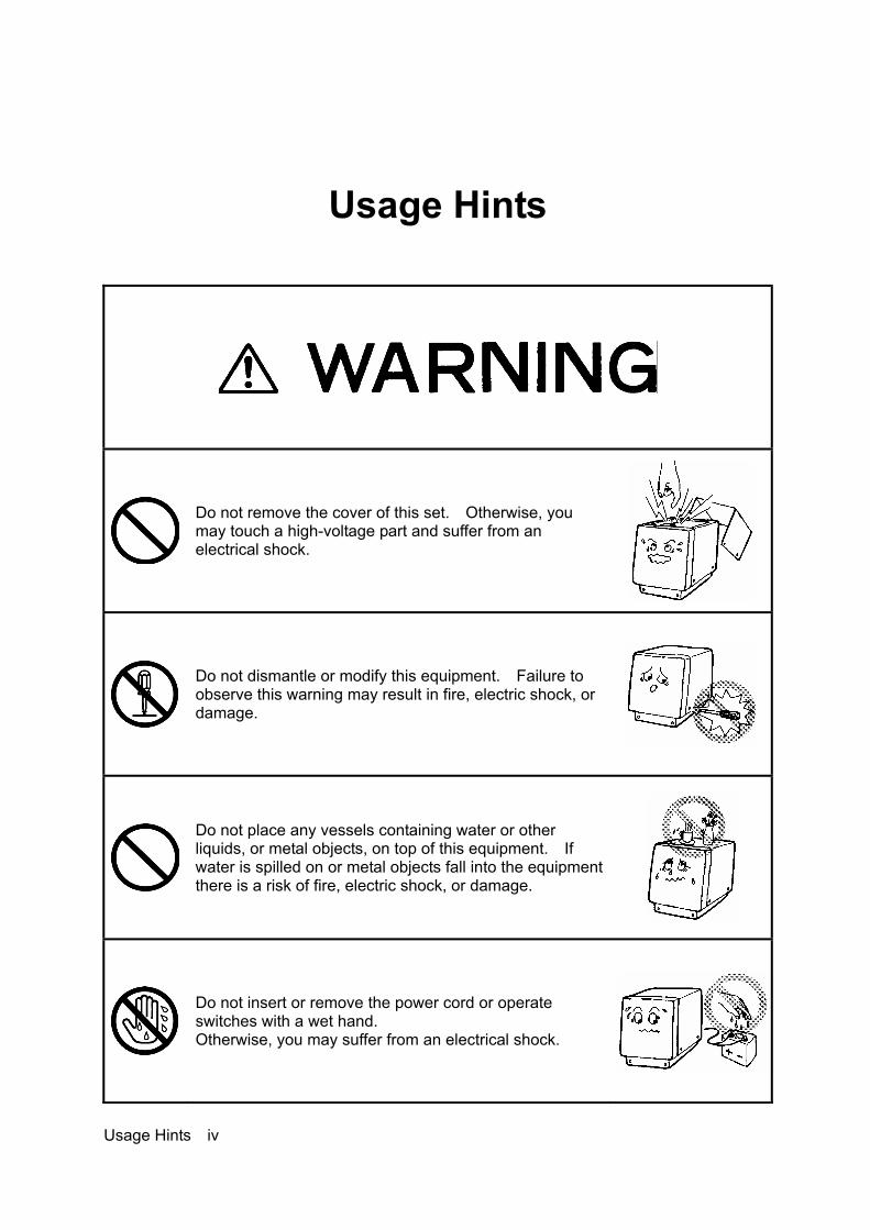
Usage Hints
Do not remove the cover of this set. Otherwise, you may touch a high-voltage part and suffer from an electrical shock.
Do not dismantle or modify this equipment. Failure to observe this warning may result in fire, electric shock, or damage.
Do not place any vessels containing water or other liquids, or metal objects, on top of this equipment. If water is spilled on or metal objects fall into the equipment there is a risk of fire, electric shock, or damage.
Do not insert or remove the power cord or operate switches with a wet hand. Otherwise, you may suffer from an electrical shock.
Usage Hints iv

Do not damage, break or modify the power cord. When a heavy object is placed on the cord or the cord is heated, pulled, or forcibly bent, the cord will be broken resulting in a fire or an electrical shock.
Do not use this set at a voltage other than the supply voltage stated on the set. Otherwise, a fire, an electrical shock, or a failure may occur.
In the event of water of metal objects falling inside the equipment, immediately turn off the power switch, then contact JRC or its agent. There is a risk of file or electric shock if you continue to use the equipment.
If you notice smoke, unusual smells, or abnormal heat coming from the equipment, immediately turn off the power switch, then contact JRC or its agent. There is a risk of fire, electric shock, or damage if you continue to use the equipment.
There are no customer-serviceable parts inside. Unauthorized inspections and repairs could cause fires and electrical shock hazards. Please call our field representative or your nearest JRC office for inspection and repair services.
Usage Hints v

Please contact JRC or its agent for the electrical installation of this equipment. Electrical installations carried out by other than the qualified staff may result in faulty operation.
Do not store or operate the equipment where subject to temperatures in excess of 55℃. High temperature may cause failures.
Do not install the equipment on unstable or unleveled surfaces. Failure to observe this condition may result in the equipment falling or toppling over, resulting in injury.
If it is cold, do not move the equipment suddenly into a warm environment and switch it on. High-voltage leaks due to condensation may result in damage to the equipment. In such situations, leave the equipment in the warm environment for about 30 minutes before switching it on.
When installing the equipment, securely connect the earth lead to the earth terminal. Failure to connect the earth may result in electric shock in the event of a fault or power leak developing.
GND
Usage Hints vi
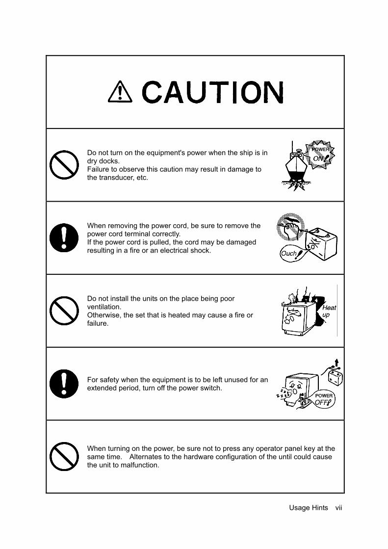
Do not turn on the equipment's power when the ship is in dry docks. Failure to observe this caution may result in damage to the transducer, etc.
When removing the power cord, be sure to remove the power cord terminal correctly. If the power cord is pulled, the cord may be damaged resulting in a fire or an electrical shock.
Do not install the units on the place being poor ventilation. Otherwise, the set that is heated may cause a fire or failure.
For safety when the equipment is to be left unused for an extended period, turn off the power switch.
When turning on the power, be sure not to press any operator panel key at the same time. Alternates to the hardware configuration of the until could cause the unit to malfunction.
Usage Hints vii
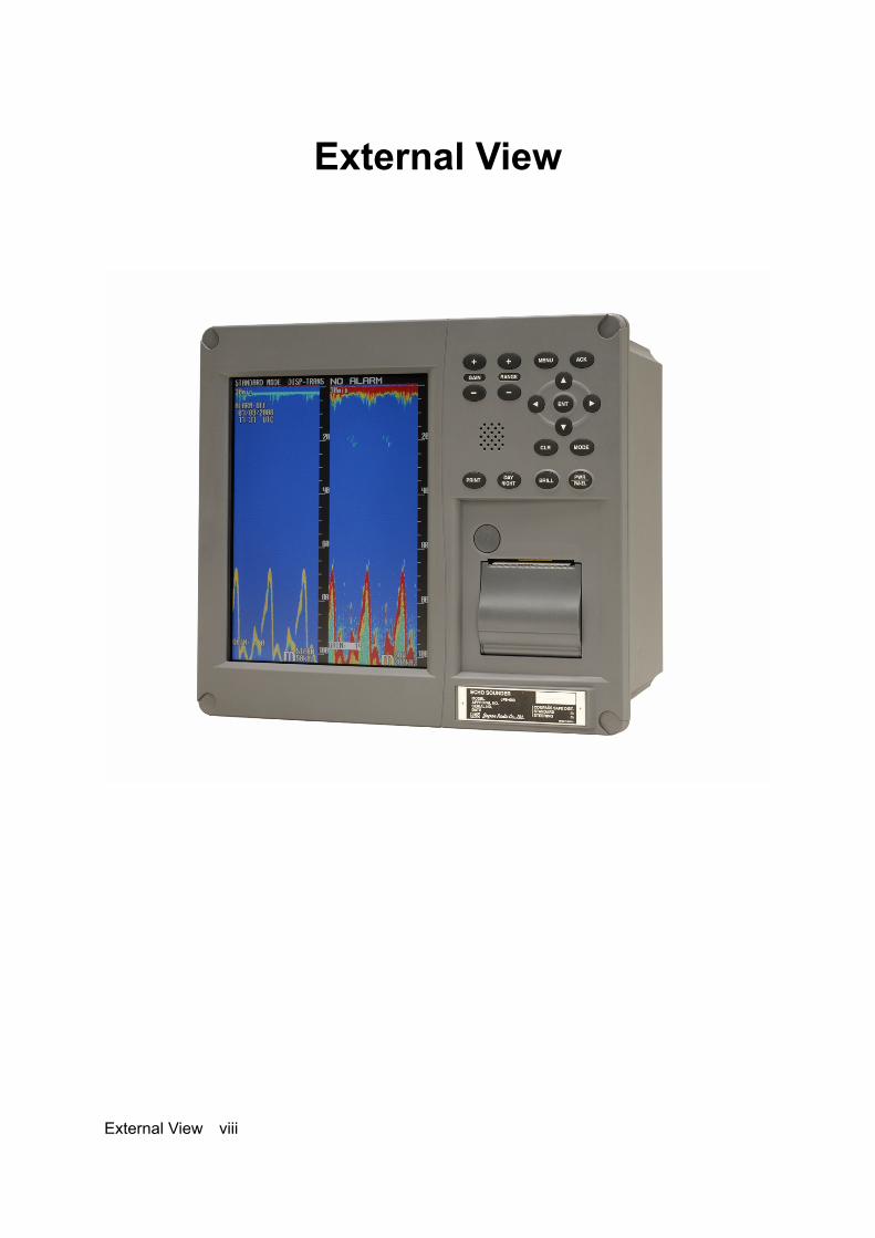
External View
External View viii

Contents General Information .................................................................................................... Before You Begin ......................................................................................................... Usage Hints .................................................................................................................. External View ............................................................................................................... Explanation of Terms .................................................................................................. 1. Introduction .............................................................................................................
1.1 Function ...........................................................................................................… 1.2 Feature ............................................................................................................…. 1.3 Components ........................................................................................................ 1.4 Construction ......................................................................................................... 1.5 System Configuration ..........................................................................................
2. Names and Functions of the Unit .......................................................................... 3. Display ................................................................................................................…..
4.1 Standard mode .................................................................................................... 4.2 History mode ..................................................................................................….. 4.3 Docking mode ..................................................................................................…
4. Operation ................................................................................................................. 4.1 Basic Operations ................................................................................................. 4.2 Menu Operations ................................................................................................. 4.3 Master Reset .......................................................................................................
5. Replacing Consumables ......................................................................................... 5.1 Replacing Recording Paper.................................................................................. 5.2 Replacing the Fuses ............................................................................................
6. Consider Installation ............................................................................................... 7. Installation ...............................................................................................................
7.1 Installing the Recorder Unit ...........................................................................… 7.2 Installing the Transducer ...................................................................................... 7.3 Connecting Components .....................................................................................
8. Troubleshooting ...................................................................................................... 9. After-sales Service ..................................................................................................
9.1 When Requesting Servicing ................................................................................ 9.2 Recommendations for Inspection and Maintenance.............................................
10. Disposal ..............................................................................................................… 10.1 Disposal of this equipment .............................................................................…
11. Specifications ....................................................................................................…. Appendix ....................................................................................................……………
i iii iv viiix 1 1 1 2 3 5 6 7 7 8 9 10 10 16 27 28 28 30 32 33 34 36 39 40 41 41 41 42 42 43 44
Information ...................................... Please refer to ‘Place of Contact’ on back cover.
Contents ix

Explanation of Terms Beam angle: The angle that sound waves spread out from the transducer. Sound waves spread out in a conical manner taking the center of the bottom surface of the transducer at the apex of the cone. Bubbling: The phenomenon where the image of the seabed is interrupted due to air bubbles caused by the ship's hull or the propeller during a voyage. IMO: stands for International Maritime Organization. MED: stands for Marine Equipment Directive. This is the directive for marine equipment in Europe. This directive unifies format approval standards implemented separately by each European. NMEA0183: NMEA stands for the National Marine Electronics Association. NMEA0183 is the format used when sending or receiving depth, position, water temperature, ship speed and other information between marine equipment. STC: Sensitivity Time Control is used for reduce shallow water clutter. Shallow seabed echo is strong and deep seabed echo is weak. So, the STC controls the sensitivity to normalize seabed echo for precision seabed tracking. Transducer: Device that emits ultrasonic waves in water and receives the signals reflected off the seabed. This is equivalent to an antenna on a radio. UTC: stands for Universal Time Coordinated. Explanation of Terms x

1. Introduction
1.1 Function The JFE-680 Echo-Sounder consists of a transducer mounted on the bottom of the ship's hull and a main unit that displays information on the depth and formation of the seabed. This information is gained by using ultrasonic waves sent from the transducer that are then reflected off the sea bottom and picked up again by the transducer. The JFE-680 also has the following functions: (1) depth alarm, (2) power fail alarm, (3) output of depth data, (4) output of depth and power fail alarms.
1.2 Feature
The JFE-680 features the following: • Tree display modes; standard, history, and docking. • Depth data for last 24 hours in memory to play back the past sounding information. • Dual frequency mode and two transducers are available in option. (*requires an optional equipment)
Conforms to the IMO Standard • When the depth becomes shallower than a previously set value, a depth alarm is issued by buzzer and LCD display. • When power is cut to the main unit, a power fail alarm is issued by buzzer and LCD display. • Contact signals can be output for both depth and power fail alarms. • Data on depths can be output.
Digital Depth Display • No need for time-consuming reading of depths using a scale against the profile of the seabed on the paper! The current depth can be seen at a glance.
Self-Diagnostic Functions • Self-diagnostic functions can be selected from a menu, improving ease of maintenance.
1. Introduction 1

1.3 Components
This section lists the components.
Standard Equipment
Name Type No. Qty. Remarks Display unit JFE-680 1 Matching box (primary) AW-154F 1 200kHz transducer mounting (primary) NKF-341 1 200kHz (with cable 20,30,40m)
AW-154F 1 200kHz Matching box (secondary) AW-154F-50 1 50kHz
NKF-341 1 200kHz (with cable 20,30,40m) Transducer mounting (secondary) NKF-345 1 50kHz (with cable 20,30,40m) Printer H-7ZPJD0384 1
BRBX05351 1 Color : MUNSELL N4 BRBX05355 1 Color : MUNSELL 7.5BG7/2
Flush mounting kit
BRBX05354 1 Color : MUNSELL 2.5G7/2
Option
Table mounting kit BRBX05340 1 1. Introduction 2

1.4 Construction
Equipment Outline The following shows the external dimensions of the JFE-680. 1. External Dimension of JFE-680
2. Dimensions of AW-154F-50/AW-154F-50 Matching box
1. Introduction 3
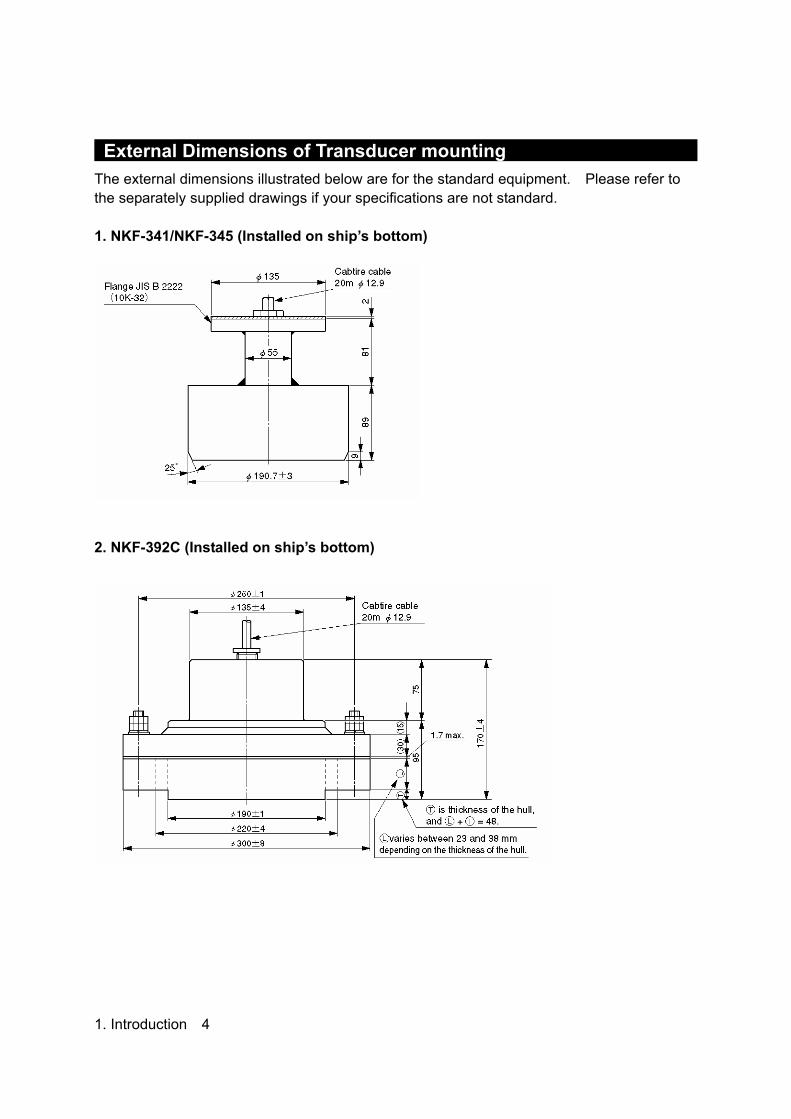
External Dimensions of Transducer mounting The external dimensions illustrated below are for the standard equipment. Please refer to the separately supplied drawings if your specifications are not standard. 1. NKF-341/NKF-345 (Installed on ship’s bottom)
2. NKF-392C (Installed on ship’s bottom)
1. Introduction 4

1.5 System Configuration
1. Introduction 5

2. Names and Function of the Unit This section describes the names and functions of the control panel and its controls.
Figure 2-1 Control Panel
No. Name Function 1 ACK Cancels the buzzer. 2 MENU Displays the menu. 3 Arrows Move a cursor. 4 ENT Selects an item. 5 MODE Switches the display modes. 6 CLR Clears an item.
7 PWR/PANEL Switches the equipment power on and off, adjusts the
brightness of the panel. Press and hold both the PWR/PANEL and the BRILL keys to turn off the power.
8 BRILL Adjusts the screen brilliance. 9 DAY NIGHT Enhances the visibility of the screen.
10 PRINT Starts printing. 11 (RANGE) +/– Switches the depth range to shallow or deep. 12 (GAIN) +/– Adjusts the sensitivity high or low.
2. Names and Functions of the Unit 6
12 11 2 1 3 4
6 5 10 9 8 7

3. Display
3.1 Standard mode (dual frequency)
3. Display 7

3.2 History mode
3. Display 8
Keel height value

3.3 Docking mode
3. Display 9

4. Operation
4.1 Basic Operations
Turning Power ON/OFF Turning Power On Press and hold the PWR/PANEL key for three seconds. Turning power OFF Press and hold both the PWR/PANEL and the BRILL keys for three seconds.
Adjusting Control Panel Illumination PANEL
Press the PWR/PANEL key, and use the arrow keys to adjust the control panel brightness. The control panel illumination can not be turned fully off, it can only be dimmed.
Adjusting Screen Brilliance BRILL
The screen brilliance is adjusted by pressing the BRILL key. Set the brilliance to optimum visibility by using the arrow keys. Note: Use the Day/Night Vision also to enhance the visibility of the screen depending in the surrounding light condition. 4. Operation 10

Setting Depth Range Each time you press the (RANGE) + key, the measuring range increases in the sequence 10, 20, 50, 100, 200, 500, 800 meters. Each time you press the (RANGE) – key, the measuring range decreases in the sequence 800, 500, 200, 100, 50, 20, 10 meters. Note: 1. As per the draft setting, the seabed image may shift outside the depth measuring range. 2. You must display the seabed, otherwise you don’t see the depth value.
Automatic Range In the Automatic range mode, the range scale is automatically adjusted. Turn on the power or press and hold both the (RANGE) + and – keys for three seconds. Once Automatic range mode is selected, the text “AUTO” will appear on the screen. The Automatic range mode is cancelled by pressing the (RANGE) + or – key. Note: 1. The Automatic range mode can be set by a dedicated menu function. 2. Default setting of the automatic range is 10m.
4. Operation 11

Adjusting Receiver Sensitivity Select the step from 0 to 30. Pressing the (GAIN) + key increases sensitivity. Pressing the (GAIN) – key decreases sensitivity. If the receiver sensitivity is set too high, noise will also be displayed on the screen, making it difficult to distinguish the seabed. The seabed color should be orange, red or color between orange and red. Adjust the sensitivity to an appropriate value by monitoring the image being plotted on the screen. (See figure below)
Increase sensitivity
Good Decrease sensitivity
Automatic Gain In the Automatic gain mode, the sensitivity is automatically adjusted. Press and hold both the (GAIN) + and – keys for three seconds. Once Automatic gain mode is selected, the text “GAIN:AUTO” will appear on the screen and LONG will be selected at STC function. The Automatic range mode is cancelled by pressing the (GAIN) + or – key. Note: 1. The Automatic gain mode can be set by a dedicated menu function. 2. Default setting of the automatic gain is 10 in the steps 0 to 20. 4. Operation 12

Selecting Display Mode Pressing the MODE key choose the display mode among STANDARD, HISTORY, and DOCKING. [Single frequency] Each press of the MODE key brings up the display mode as follows, “Standard mode, History mode, Docking mode.” [Dual frequency] Each press of the MODE key brings up the display mode as follows, “Single frequency standard mode (primary), Single frequency standard mode (secondary), Dual frequency standard mode, Single frequency history mode (primary), Single frequency history mode (secondary), Docking mode.”
Adjusting Screen Visibility Use the Day/Night Vision to enhance the visibility of the screen depending in the surrounding light condition. Select day1, day2, night1, or night2. Note: The color be set by a dedicated menu function.
Canceling the Buzzer Press the ACK key to cancel the depth alarm buzzer.
4. Operation 13
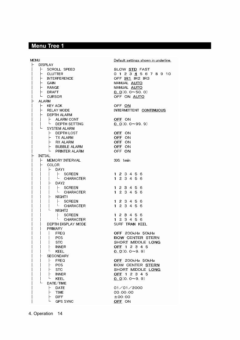
Menu Tree 1
4. Operation 14

Menu Tree 2
4. Operation 15
4.2 Menu Operations
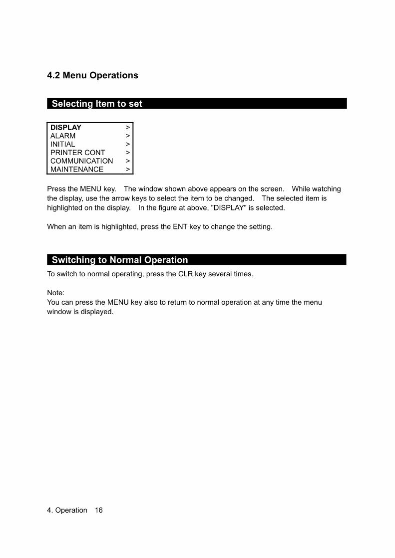
Selecting Item to set DISPLAY ALARM INITIAL PRINTER CONT COMMUNICATION MAINTENANCE
> > > > > >
Press the MENU key. The window shown above appears on the screen. While watching the display, use the arrow keys to select the item to be changed. The selected item is highlighted on the display. In the figure at above, "DISPLAY" is selected. When an item is highlighted, press the ENT key to change the setting.
Switching to Normal Operation To switch to normal operating, press the CLR key several times. Note: You can press the MENU key also to return to normal operation at any time the menu window is displayed. 4. Operation 16

Display Settings DISPLAY
SCROLL SPEED CLUTTER INTERFERENCE GAIN RANGE DRAFT CURSOR
FAST 4 OFF AUTO MANUAL 6.1 ON
Scroll speed: Choose one among slow, standard, and fast. Clutter: Suppresses small noise. Choose one among 11 levels. “0” is the weakest. Interference: Eliminates noise from other boats. “OFF” does not eliminate the noise. “IR1” compares it with the last data. “IR2” compares it with the last two data. “IR3” compares it with the last three data. Gain: Choose manual or automatic. Range: Choose manual or automatic. Draft: Enter the desired value. The draft can be set between 0.0 and 50.0 m in steps of 0.1 m. Cursor: “OFF” does not display the cursor. “ON” displays the cursor. “AUTO” displays the cursor for 30 seconds after the cursor movement is stopped.
Alarm Settings ALARM
KEY ACK RELAY MODE DEPTH ALARM SYSTEM ALARM
ON CONTINUOUS> >
Key acknowledgement: Enables / disables the keypads beep. Relay mode: Choose intermittent or continuous.
4. Operation 17

Setting Depth Alarm DEPTH SETTING
20.0 Display the window shown above. Pressing and holding the upward-arrow key increases the depth setting of the depth alarm. Pressing and holding the downward-arrow key decreases the depth setting of the depth alarm. Press the ENT key to finish setting. If the measured depth is less than the set depth alarm value, a warning character blinks and the buzzer sounds. Notes: 1. The buzzer sounds for depth, power fail, and system alarms. You can check which alarm
is being issued from the blinking characters. 2. If, due to bubbling, etc., it is not possible to discriminate the sea bottom, it is also not
possible to trigger the depth alarm. When sailing in shallow waters, please check the sea bottom reflected on the screen.
3. The alarm tone sounds from the hole at the front panel. Do not block this hole. The currently set depth alarm is displayed on the screen. Note: The depth can be set between 0.0 and 99.9 meters.
Activating/deactivating the alarm Highlight the alarm item you wish to activate or deactivate. Select OFF to deactivate the alarm. Select ON to activate the alarm. Press the ENT key to finish setting. 4. Operation 18

Initial Settings INITIAL
MEMORY INTERVAL COLOR DEPTH DISPLAY MODE PRIMARY SECONDARY DATE/TIME
30S > TRAN> > >
Memory interval: “30S” saves the sounding data every 24 hours. “1min” saves the sounding data every 12 hours. Color: Adjust color of the screen and character for the DAY NIGHT key. Depth display mode: “SURF” displays the depth below water surface. “TRAN” displays the depth below the transducer. “KEEL” displays the depth below the keel. (see figure A) Primary: Enter the data of the primary transducer; frequency, position, STC, inner, and keel. Secondary: Enter the data of the secondary transducer; frequency, position, STC, inner, and keel. Date/time: Set the time, the date, and a time difference. GPS synchronization “OFF” uses the inner clock. GPS synchronization “ON” uses the ZDA data to synchronize the inner clock. 4. Operation 19

Printer Control Settings PRINTER CONT
PRINTER PRINT MODE LOG LENGTH SPEED
ON COPY 10min 4800bps
Printer: Enables / disables to print. Print mode: “COPY” prints the data displayed on the present screen. “HISTORY” prints all the saved data graphically. “LOG” prints a specific period of the saved data. (see figure C for example) Log length: Choose a log length for “LOG” which explained just above. Speed: Choose a baud rate of the printer port.
Figure C
4. Operation 20

Setting Format for Depth Data Output DEPTH
Ver1.5 Ver2.3 ALL
Display the window shown above. The format changes each time you press the up or downward-arrow key. Notes: 1. There are three output formats: NMEA0183V2.3, NMEA0183V1.5, or ALL. 2. In the case of NMEA0183V2.3, only "SDDPT" sentences are output.
$SDDPT, xxx.x, x.x, x.x *hh (CR)(LF) (1) (2) (3) (4)
(1) Depth measured from the transducer regardless of the depth display mode setting (in
meters only.) (2) According to the depth display mode:
DISP-SURF: Draft value (no + or – sign preceding values) DISP-TRANS: 0.0 DISP-KEEL: Keel height compensation (– sign preceding values)
(3) Measuring range: RANGE (in meters only) (4) Checksum (result after each ASCII code of every character between "S" just after "$" and
"X" just before " * " is EXORed.) 3. In the case of NMEA0183V1.5, the output sentence varies according to the depth display
mode setting. • When DISP-SURF is set, only the "SDDBS" sentence is output.
$SDDBS, xxx.x, f, xxx.x, M, xxx.x, F(CR)(LF) (1) (2) (3)
• When DISP-TRANS is set, only the "SDDBT" sentence is output. $SDDBT, xxx.x, f, xxx.x, M, xxx.x, F(CR)(LF)
(1) (2) (3) • When DISP-KEEL is set, only the "SDDBK" sentence is output.
$SDDBK, xxx.x, f, xxx.x, M, xxx.x, F(CR)(LF) (1) (2) (3)
The field values are the same in each of the three sentence types: (1) Depth value after compensation (in feet) (2) Depth value after compensation (in meters) (3) Depth value after compensation (in fathoms) (4) No check sum
4. Operation 21
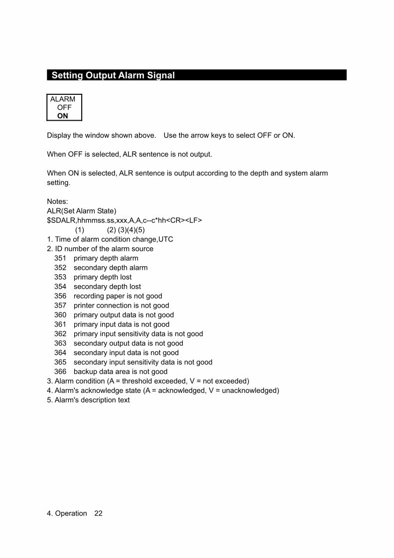
Setting Output Alarm Signal ALARM
OFF ON
Display the window shown above. Use the arrow keys to select OFF or ON. When OFF is selected, ALR sentence is not output. When ON is selected, ALR sentence is output according to the depth and system alarm setting. Notes: ALR(Set Alarm State) $SDALR,hhmmss.ss,xxx,A,A,c--c*hh<CR><LF> (1) (2) (3)(4)(5) 1. Time of alarm condition change,UTC 2. ID number of the alarm source
351 primary depth alarm 352 secondary depth alarm 353 primary depth lost 354 secondary depth lost 356 recording paper is not good 357 printer connection is not good 360 primary output data is not good 361 primary input data is not good 362 primary input sensitivity data is not good 363 secondary output data is not good 364 secondary input data is not good 365 secondary input sensitivity data is not good 366 backup data area is not good
3. Alarm condition (A = threshold exceeded, V = not exceeded) 4. Alarm's acknowledge state (A = acknowledged, V = unacknowledged) 5. Alarm's description text 4. Operation 22
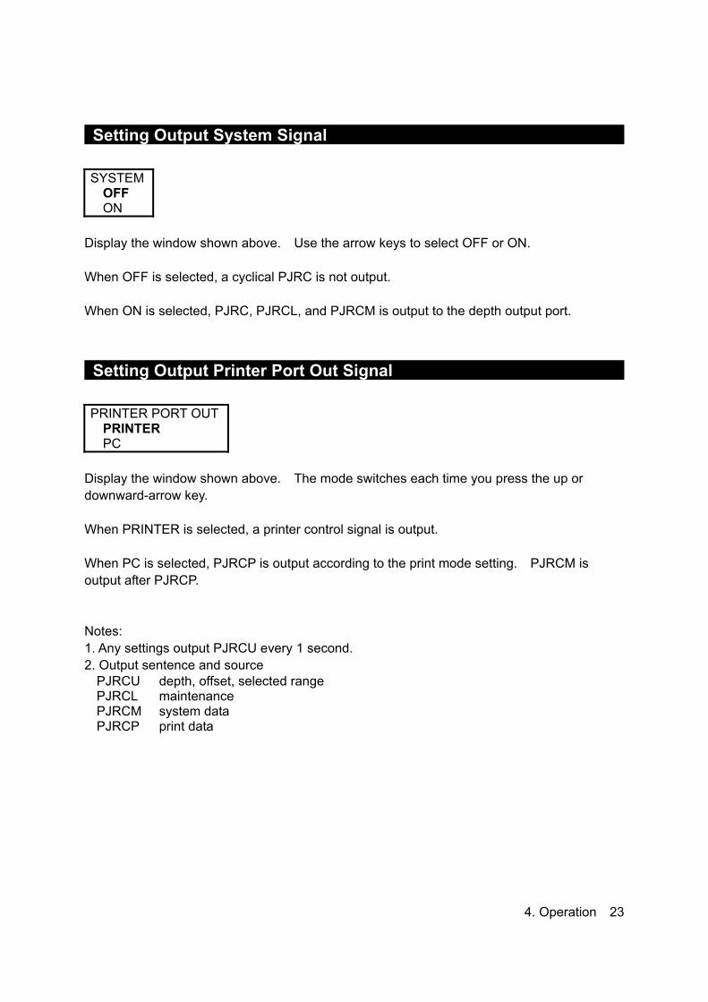
Setting Output System Signal SYSTEM
OFF ON
Display the window shown above. Use the arrow keys to select OFF or ON. When OFF is selected, a cyclical PJRC is not output. When ON is selected, PJRC, PJRCL, and PJRCM is output to the depth output port.
Setting Output Printer Port Out Signal PRINTER PORT OUT
PRINTER PC
Display the window shown above. The mode switches each time you press the up or downward-arrow key. When PRINTER is selected, a printer control signal is output. When PC is selected, PJRCP is output according to the print mode setting. PJRCM is output after PJRCP. Notes: 1. Any settings output PJRCU every 1 second. 2. Output sentence and source
PJRCU depth, offset, selected range PJRCL maintenance PJRCM system data PJRCP print data
4. Operation 23

Memory Test SELF TEST
CONTROL UNIT LCD UNIT KEY UNIT PRINTER TEST ALARM TEST
> > > > > >
Display the window shown above. Use the up or downward-arrow key to select CONTROL UNIT. Press the ENT key to start the memory test. The results of the memory test are shown on the screen. • During testing, nothing is shown on the screen. • The results are shown for each PROM, SRAM, and VRAM. If OK : OK If no good : NG If NG is displayed, the Transducer Controller is faulty and requires servicing. (See the list of offices at the end of this manual.)
LCD Check SELF TEST
CONTROL UNIT LCD UNIT KEY UNIT PRINTER TEST ALARM TEST
> > > > > >
Display the window shown above. Use the up or downward-arrow key to select color. Press the CLR key to exit. This test fills the whole screen with colors, which are black, red, green, blue, and white. The color changes each time you press the up or downward-arrow key. If there is any dropout, the Panel or Transducer Controller may be faulty. Please contact JRC or its agent. (See the list of offices at the end of this manual.) 4. Operation 24

Panel Circuit Operation Check KEY UNIT BRILL
Display the window shown above. Press each location on the panel. • If operation is OK, a key name is displayed in the key unit window. In the figure at above, the result of that the BRILL key is pressed. • If operation is NG, nothing remains. If faulty, the Panel or Transducer Controller may be faulty and may require servicing. (See the list of offices at the end of this manual.)
Printer Test SELF TEST
CONTROL UNIT LCD UNIT KEY UNIT PRINTER TEST ALARM TEST
> > > > > >
Display the window shown above. Use the up or downward-arrow key to select PRINTER TEST. Press the ENT key to start the recording paper surface check. This check prints a test pattern on the recording paper. (See figure B for example) If the printing is blurred, it may be faulty and may require servicing. Please contact JRC or its agent. (See the list of offices at the end of this manual.)
Figure B
4. Operation 25

Alarm Test “OFF” disables the alarm test. “DEPTH ALARM” displays the center of the depth scale. “SYSTEM ALARM” enables the preset depth lost alarm.
Maintenance Functions MAINTENANCE
SELF TEST ALARM LOG ALARM LOG OUT ALARM LOG DELLINE MONITOR RX MONITOR SYSTEM No.
> > > > > > >
Alarm log: Displays the alarm log by pressing the ENT key. Pressing the CLR key brings up the Maintenance Menu window. Alarm log out: Outputs the alarm log to the normal port, the printer, or the printer port by pressing the ENT key. Alarm log deletion: Deletes all the alarm log by pressing the ENT key. Line monitor: “NAV/DEPTH” displays the Input/output data of navigation and depth by pressing the ENT key. “ALR” displays the Input/output data of ALR by pressing the ENT key. “PRINTER” displays the Input/output data of the printer port by pressing the ENT key. Pressing the CLR key brings up the Maintenance Menu window. RX monitor: Displays the present status of the receiver by pressing the ENT key.
Program Version No. SYSTEM No.
07/09/2006 Ver 00.03
The program version No. is displayed on the system number window. 4. Operation 26

5.3 Master Reset
Executing Standard Default Settings Turn OFF the power, then turn ON the power while simultaneously pressing and holding both the MENU and CLR keys. After resetting the equipment to the standard defaults, the frequency setting menu window, which said please do connection setting of transducers, appears on the screen. You cannot abort this operation after the frequency setting menu window appeared on the screen. You have to select the frequency to switch to normal operation. Note: See Menu tree for the standard defaults.
4. Operation 27

5. Replacing Consumables
5.1 Replacing Recording Paper Be sure to replace with the recording paper specified by JRC.
Name Remarks Recording paper The red line will appear when there is only about one meter of
recording paper left on the roll.
Handle the paper cutter carefully not to cut your hand.
(1) Press the paper cover open button, and open the paper cover. (2) Set a paper roll as shown in the figure. 5. Replacing Consumables 28

(3) Close the paper cover by pressing the both ends of the cover, with the tip end of the
paper emerging from the printer. Note: Turn off the power before you open the paper cover, otherwise warring alarm goes off.
5. Replacing Consumables 29

5.2 Replacing the Fuses Use only the specified fuses, and check the cause of the fuses blowing before replacing them. Be sure to turn OFF the main power switch (to the side marked O) on the power supply (CQD-2083) before replacing the fuses.
No. Type No. Spec. Part Code Remarks F1 250V 1A TLC 5A 250V 1A 5ZFCA00147 F2 MF51NR 250V 0.5 250V 0.5A 5ZFGD00019 F3 MF51NR 250V 2 250V 2A 5ZFGD00022
Fuse Positions
5. Replacing Consumables 30

(1) Replacing Main Power Supply Fuse F1 One reason for this fuse blowing is a faulty cable attached to the power supply. Check the cables before replacing the fuse, then turn the power on. If the fuse blows again, the Power Supply (CBD-1811) may be faulty. Contact JRC or its agent.
(2) Replacing 24VDC Input Power Fail Alarm Fuse F2 One reason for this fuse blowing is the input of an abnormal voltage. Check the input voltage at J11 pins (3) and (4) of the Interface Block. Check that the voltage is as rated (24VDC) (operating voltage: 21.5 to 31.5VDC) before replacing the fuse. If the fuse blows again, the Interface Block (CGD-2083), the Power Supply (CBD-1811), the Control Block (OCK-963), or the Cables (CFQ-9139, CFQ-9140, CFQ-9148) may be faulty. Contact JRC or its agent. (See the list of offices at the end of this manual.)
(3) Replacing Built-in Printer Fuse F3 One reason for this fuse blowing is an overcurrent in a built-in printer or an external device connected to J13 pins (1) and (2) of the interface block. Temporarily remove the cable to the external device. If the fuse blows again, the Interface Block (CQD-2083), the built-in printer (DPU30-OBJ-E), or the cable (CFQ-9142) may be faulty. Contact JRC or its agent. (See the list of offices at the end of this manual.)
5. Replacing Consumables 31

6. Consider Installation • Do not install the JFE-680 where subject to the following conditions as such conditions may cause failures and reduce the life of the equipment. 1. Where liable to be splashed with water. 2. Where ventilation is poor. • Do not coat the part of the transducer that outputs the ultrasonic waves (the rubber part of the tank on the ship's bottom) with the hull coating as this will deteriorate performance. 6. Consider Installation 32

7. Installation
When installing the equipment, securely connect the earth lead to the earth terminal. Failure to connect the earth may result in electric shock in the event of a fault or power leak developing.
Do not install or operate the equipment where subject to temperatures 55°C or higher or –15°C or lower. Failure to observe this caution may result in fire or damage.
Do not install the equipment on unstable or unlevel surfaces. Failure to observe this condition may result in the equipment falling or toppling over, resulting in injury.
Take care when laying the transducer cable, power cable, and earth lead as positioning has an affect on electromagnetic interference. There is a risk of interfering with other equipment or the echo-sounder being interfered with by the other equipment.
After installing the echo-sounder, turn on the power to all other equipment to check for interference with or from all the equipment. Interference may cause malfunctions.
7. Installation 33

7.1 Installing the Recorder Unit
Flush-Mounted Equipment
Figure 3-1 7. Installation 34

Wall-Mounted Equipment
Figure 3-2
7. Installation 35

7.2 Installing the Transducer
The external dimensions illustrated below are for the standard equipment. Please refer to the separately supplied drawings if your specifications are not standard.
NKF-341
7. Installation 36

NKF-345
7. Installation 37

NKF-392C
7. Installation 38

7.3 Connecting Components
Notes: 1. The shield of each cable must be securely attached to the connectors and must not
contact any other connectors, etc. 2. Casings must be grounded securely to the ship’s hull using copper plates. 3. The exterior is to be grounded to the ship’s hull cable bands. 4. Select NC/NO for Depth Alarm and Power Fail Alarm.
7. Installation 39

8. Troubleshooting
The table below provides simple troubleshooting procedures which you may follow to restore normal operation. If you cannot restore normal operation, contact your dealer. SYMPTOM PROBABLE CAUSES REMEDY
The power cord is not plugged Plug the power cord The power cord is damaged Repair the cord The breaker of your ship is off Turn on the breaker High or low power supply Check the supply voltage
No picture
Fuse blown Replace the fuse Transducer cable is not connected
Connect the cable
Transducer cable damaged Repair the cable Transducer is not connected Connect the transducer Wrong installation of the transducer
Check the transducer
No echo sounding picture
Frequency setting is wrong Check the frequency settingLow sensitivity Increase the gain Muddy seabed Increase the gain Marine life on the transducer Remove marine life from the
transducer. The transducer is damaged Replace the transducer Draft value is not collect Adjust draft value
Irregular display
Suspect dirty water Decrease the gain Noise from generator Check the generator Wrong installation of the ground wire
Relocate the ground wire
The transducer cable is damaged
Repair the transducer cable
Heavy noise
The transducer cable and the power code are placed too close.
Relocate the transducer cable and the power code not too close.
The printer won’t start Fuse blown Replace the fuse 8. Troubleshooting 40

9. After-sales Service
9.1 When Requesting Servicing If you suspect a fault, stop using the equipment and contact JRC or its agent. Servicing Under Warranty When the fault develops while the equipment is being used as indicated in the Instruction Manual, the equipment will be repaired free of charge. However, if the fault occurs as the result of misuse, negligence, natural disaster, fire, or other acts of God, a charge will be made for its repair. Servicing Out of Warranty If the fault can be rectified by servicing the equipment, the repair will be made at your expense. Details to be Submitted - Name, type No., month and year of manufacture, and serial number; - Nature of fault (in as much detail as possible); - Contact details (your name, address and phone number, etc.)
9.2 Recommendations for Inspection and Maintenance Depending on the conditions of usage, the performance may deteriorate due to the aging of components. In such conditions, please consult JRC or its agent for inspection and maintenance, as distinct from the daily care you normally give your equipment. Note that such inspection and maintenance is subject to charge. Please consult JRC or its agent for further details of any part of the afterservice conditions. Contact: See list at end of manual.
9. After-sales Service 41

10. Disposal
10.1 Disposal of this equipment Please dispose of this equipment following the guidelines of the local body governing the location at which the equipment is disposed of. 10. Disposal 42

11. Specifications Display 10.4 inch TFT LCD (640 x 480 pixels) Frequency 200kHz / 50kHz Echo color 8 colors or 8 level monochrome Digital depth 4 digit (0.1m) Range 10, 20, 50, 100, 200, 500, 800m Depth accuracy ±2.5% Minimum sounding depth 200kHz : 1.0m, 50kHz : 2m
Draft adjust 50m in 0.1m steps 171PRR (10, 20, 50m) 86PRR (100, 200m) TX pulse
repetition rate 43PRR (500, 800m) Presentation mode Standard, History, Docking
Time range of echo display 5, 10, 20, 30min
Auto function Gain, Range Alarm function Depth, Power fail, System error Preview function 24hour
200kHz : UT-200ND Transducer 50kHz : UT-50MD 100-115/200-230VAC±15%, 50Hz/60Hz±5% Power supply 24VDC (only use for power fail monitoring)
Power consumption Less than 50W
Water proofing IPX2 drip proof Input nav. data IEC61162-1NMEA0183 RMA, RMC, GGA, GLL, VTG, ZDA Input ACK signal IEC61162-1NMEA0183 ALR Input signals Power fail alarm ACK:
(Contact input: 12VDC 2.4mA, current control: 12VDC 1.2mA) Depth alarm ACK, System alarm ACK: (Contact input: 5VDC 5mA, current control: 12VDC 1.2mA)
Output depth value data
IEC61162-1 (NMEA0183 V1.5)IEC61162-1 (NMEA0183 V2.3)
DBS, DBT, DBKDPT
every 1 second every 1 second
Output alarm data IEC61162-1 (NMEA0183) ALR every 1 second Output system data (IEC61162-1)
PJRCL PJRCM (90) PJRCM (88, 89)
UTC UTC
every 10 seconds every 0 to 4 hours every 0 to 4 hours
Output PC data PJRCP Output signals Power fail alarm, Depth alarm, System alarm:
(Relay contact output: rated load 120VAC 10A, 30VDC 8A, NO/NC) Ambient temperature
–15°C to 55°C / operating –25°C to 70°C / storage
Relative humidity less than 93%RH under 40°C condition (non-condensing) / operating less than 93%RH under 40°C condition (non-condensing) / storage
11. Specification 43

Appendix Noise
Bubble Noise Bubble Interruption
Interference Noise from other ship
Plankton layer Appendix 44

Actual Pictures
Zero line Seabed
DISP TRANS DISP SURF
DISP KEEL
figure A
Seabed
Zero line Third reflection of bottom
Second reflection of bottom Seabed In case of a shallow seabed or when increasing the amplifier sensitivity, two seabed lines may be recorded. This results from a multi-reflection of ultra-sonic wave between the seabed and hull bottom or surface of sea, in such manner: An emitted ultrasonic wave once reflected at the seabed returns toward the transducer or surface or sea but reflected at the hull bottom or surface of sea and again reflected at the seabed toward the transducer. Such multiple recording of the seabed may appear due to change of bottom quality. A double or triple reflection may be sometimes recorded. In any case, a first reflection recording from the zero line represents a real seabed return. A first, second and third reflection lines of seabed arrange with approximately equal spacing on the recording. In addition, the shade of the reflection lines fades little by little away from the fast line on the recording. From these conditions, they can be easily identified as a multireflection.
Appendix 45

Seabed Quality Change
Mud Rock
In case of a hard seabed composed of rocks etc., its return trails long, as shown in right chart. In case of a soft seabed made of mud, seaweed, etc., they poorly reflect an ultrasonic wave to result in thin recording of the seabed with short trail. The seabed quality can be more sufficiently identified with use of wider beam angle and longer pulsewidth. Usually lower frequency is used. Appendix 46
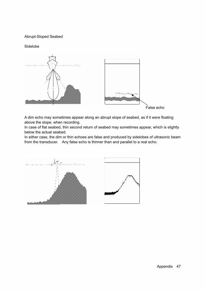
Abrupt-Sloped Seabed Sidelobe
False echo A dim echo may sometimes appear along an abrupt slope of seabed, as if it were floating above the slope, when recording. In case of flat seabed, thin second return of seabed may sometimes appear, which is slightly below the actual seabed. In either case, the dim or thin echoes are false and produced by sidelobes of ultrasonic beam from the transducer. Any false echo is thinner than and parallel to a real echo.
Appendix 47

The echo of a seabed with abrupt slope is recorded as a lone difficult to see and less discriminative, since it tends to accompany with a false echo due to the sidelobe and the inherent property of directivity. In particular, a seabed with abrupt slope and heavily rugged surface provided an echo very difficult to display on the recording. Appendix 48

7ZPNB0043
形式名(Type): JFE-680 名称(Name): Echo Sounder
铅 汞 镉 六价铬 多溴联苯 多溴二苯醚(Pb) (Hg) (Cd) (Cr6+) (PBB) (PBDE)
记录装置(Recorder Unit) × × × × × ×
船底装置(Hull-Bottom Unit) × × × × × ×
外部设备(Peripherals) ・选择(Options) ・打印机(Printer) ・电线类(Cables) ・手册(Documennts)
× ○ × × × ×
JRC Code No. : 7ZPNA2012
RE: 中华人民共和国电子信息产品污染控制管理办法 Management Methods on Control of Pollution from Electronics Information Products of the People's Republic of China
○:表示该有毒有害物质在该部件所有均质材料中的含量均在SJ/T11306-2006 标准规定的限量要求以下。 (Indicates that this toxic, or hazardous substance contained in all of the homogeneous materials for this part is below the requirement in SJ/T11363-2006.)×:表示该有毒有害物质至少在该部件的某一均质材料中的含量超出SJ/T11363-2006 标准规定的限量要求。
(Indicates that this toxic or hazardous substance contained in at least one of the homogeneous materials used for this part is above the limit requirement in SJ/T 11363-2006.)
电子信息产品有害物资申明
部件名称(Part name)
有毒有害物质或元素
(Toxic and Hazardous Substances and Elements)
日本无线株式会社
Declaration on toxic & hazardous substances or elementsof Electronic Information Products
(Names & Content of toxic and hazardous substances or elements)
Japan Radio Company Limited
有毒有害物质或元素的名称及含量
- 1 / 1 -

01ETM ISO 9001, ISO 14001 Certified
Printed in Japan
Marine Service [email protected]
Telephone :Facsimile :e-mail :
AMSTERDAM BranchTelephone :Facsimile :e-mail :
SEATTLE BranchTelephone :Facsimile :e-mail :
CODE No.7ZPNA2012
APR. 2007 Edition 1 JRC
Not use the asbestos
For further information,contact:
URL http://www.jrc.co.jp
INMARSAT-C INMARSAT-CMOBILE EARTH STATIONMOBILE EARTH STATION
SHIP SECURITY ALERT SYSTEM OPTIONSHIP SECURITY ALERT SYSTEM OPTION
JUE-85JUE-85
OPERATIONOPERATIONMANUALMANUAL