instruction manual - ieb.de classic... · 2 safety 7 2 safety 2.1 general information the...
TRANSCRIPT

Instruction Manual Revision no.: DE-0008

Preamble
Information regarding this instruction manual
This ORIGINAL INSTRUCTION MANUAL provides the knowledge required for the safe operation of the battery charger. All information is described in a short and clear manner. Chapters and pages are numbered continuously. This instruction manual documents the Filon CLASSIC battery charger types. The corresponding data is listed in the appendix “Technical data“. Ensure that the appropriate description of the available battery charger is used during operation and performance of maintenance work. Our battery chargers are subject to continuous further development. Please understand that we have to reserve the right to make changes in form, features and technology. Thus, no claims can be derived from the information contained in this instruction manual regarding specific characteristics of the battery charger.
Copyright
The copyright remains with the company Industrie Elektronik Brilon GmbH.
Industrie Elektronik Brilon GmbH
Almerfeldweg 40 59929 Brilon, Germany Ph.: +49 2961/9607-0 Fax: +49 2961/9607-77
www.ieb.de – [email protected]

Contents
1 General information............................................................................................................................... 6
1.1 Purpose of the instruction manual ...................................................................................................... 6
2 Safety ............................................................................................................................................... 7
2.1 General information ............................................................................................................................ 7
2.2 Information regarding signs and symbols ........................................................................................... 8
2.3 Personnel qualification ....................................................................................................................... 9
2.3.1 Commercial use .............................................................................................................................. 9
2.4 Intended use .................................................................................................................................... 10
2.5 Safety instructions regarding troubleshooting, maintenance and repair ........................................... 12
3 Product information ............................................................................................................................. 13
3.1 Description of the product and its function ....................................................................................... 13
3.2 Type designation .............................................................................................................................. 13
3.3 Description of the accessories and their function ............................................................................. 13
3.3.1 Charging plug ................................................................................................................................ 13
3.4 Residual risk .................................................................................................................................... 14
3.5 Description of the safety devices...................................................................................................... 16
3.6 Markings and signs on the charger .................................................................................................. 17
3.6.1 Type plate (example) .................................................................................................................... 17
3.6.2 QR code (example) ....................................................................................................................... 17
4 Assembly and commissioning ............................................................................................................. 18
4.1 Safety instructions regarding assembly and installation ................................................................... 18
4.2 Scope of delivery.............................................................................................................................. 19
4.3 Requirements regarding the place of use ........................................................................................ 19
4.4 Assembly / Installation of the charger and placing the battery ......................................................... 20
4.5 Mains connection and fuses ............................................................................................................. 22
4.6 Connecting the charger to the supply network ................................................................................. 23
4.7 Transformer tapping ......................................................................................................................... 24
4.7.1 Wa single-phase ........................................................................................................................... 24
4.7.2 Wa three-phase current ................................................................................................................ 26
4.7.3 Wa-Pulse single-phase ................................................................................................................. 27
4.7.4 Wa-Pulse three-phase current ...................................................................................................... 29
4.7.5 WoWa single-phase ...................................................................................................................... 30
4.7.6 WoWa three-phase current ........................................................................................................... 32
4.8 Initial commissioning and functional test .......................................................................................... 33
5 Operation ............................................................................................................................................ 34
5.1 Operating instructions for the IUIa battery charger ........................................................................... 34
5.1.1 Functional description and charge monitoring ............................................................................... 34
5.1.2 Signalling and operating state ....................................................................................................... 34

Contents 5
5.1.3 Operating errors (error 2-23) ......................................................................................................... 34
5.1.4 System errors (errors 24-99) ......................................................................................................... 35
5.1.5 Safety function of the electronic charging switch ........................................................................... 35
5.2 Operating instructions for the Wa / WoWa / EC / Pulse / Aquamatik battery chargers ..................... 35
5.2.1 Functional description and charge monitoring ............................................................................... 35
5.2.2 Signalling and operating state ....................................................................................................... 35
5.2.3 Safety function of the electronic charging switch ........................................................................... 36
5.3 Visual inspection prior to commissioning ......................................................................................... 36
5.4 Activities prior to charging ................................................................................................................ 37
5.5 Device options (o) ............................................................................................................................ 38
5.5.1 Charging process with electrolyte circulation (o) ........................................................................... 38
5.5.2 Start-up block (o) ........................................................................................................................... 38
5.5.3 Charging process with temperature compensation (o) .................................................................. 38
5.5.4 External charging indicator (traffic light display) (o) ....................................................................... 38
5.5.5 Aquamatik (o) ................................................................................................................................ 39
6 Maintenance and repair ...................................................................................................................... 41
6.1 Cleaning, inspection and maintenance ............................................................................................ 41
6.2 Spare parts ...................................................................................................................................... 42
7 Disposal 43
8 Appendix 44
8.1 Charging plug ................................................................................................................................... 44
8.1.1 MICOMP Light IEB 601 charging plug for Wa / W0Wa chargers .................................................. 44
8.1.2 MICOMP Light IEB 602 charging plug for Wa / W0Wa chargers with options (EC, Aquamatik,
Pulse, etc.) 45
8.1.3 MICOMP Light IEB 601_1-3 charging plug for Wa / W0Wa chargers ........................................... 46
8.1.4 MICOMP Light IEB 602_1-2 charging plug for Wa / W0Wa chargers with options (EC, Aquamatik,
Pulse, etc.) 47
8.2 Circuit diagram Wa / WoWa single-phase ........................................................................................ 48
8.3 Circuit diagram Wa / WoWa single-phase with Pulse ...................................................................... 49
8.4 Circuit diagram Wa / WoWa single-phase with EC .......................................................................... 50
8.5 Circuit diagram Wa / WoWa single-phase with Aquamatik .............................................................. 51
8.6 Circuit diagram Wa / WoWa three-phase ......................................................................................... 52
9 Technical data - Standards ................................................................................................................. 53

6 1 General information
1 General information
1.1 Purpose of the instruction manual
Purpose of this instruction manual is to enable the intended use and safe operation of the FILON CLASSIC battery chargers (hereinafter referred to as “charger”). The instruction manual must always be available and kept in an easily accessible location near the charger. Any person assigned with the operation of the charger (which involves transport, assembly and installation, operation, maintenance and disassembly) must read and apply the instruction manual. In addition to the instruction manual, all mandatory directives, standards and laws for safe and proper working in the country and place of use must be observed, when the charger is used for commercial purposes. Further information in addition to this manual can be provided by the experts of the manufacturer and/or supplier. All documents are protected by copyright laws. The documents and their contents shall not be reproduced or transferred in any form without express permission.

2 Safety 7
2 Safety
2.1 General information
The instruction manual is an integral part of the charger.
The operator has to ensure that the instruction manual is available near the charger at any time and that the operating personnel are made aware of the directives mentioned in this manual. The instruction manual is to be supplemented by the operator regarding the instructions due to national regulations for accident prevention and environmental protection, including the information on the responsibilities of supervision and obligations to report for the observance of operational specifics, e.g. concerning labour organisations, operational sequences and appointed personnel. In addition to the instruction manual and to the mandatory regulations for accident prevention in the country and place of use, the generally recognised technical rules for safe and proper working must also be observed.
8 2 Safety
2.2 Information regarding signs and symbols
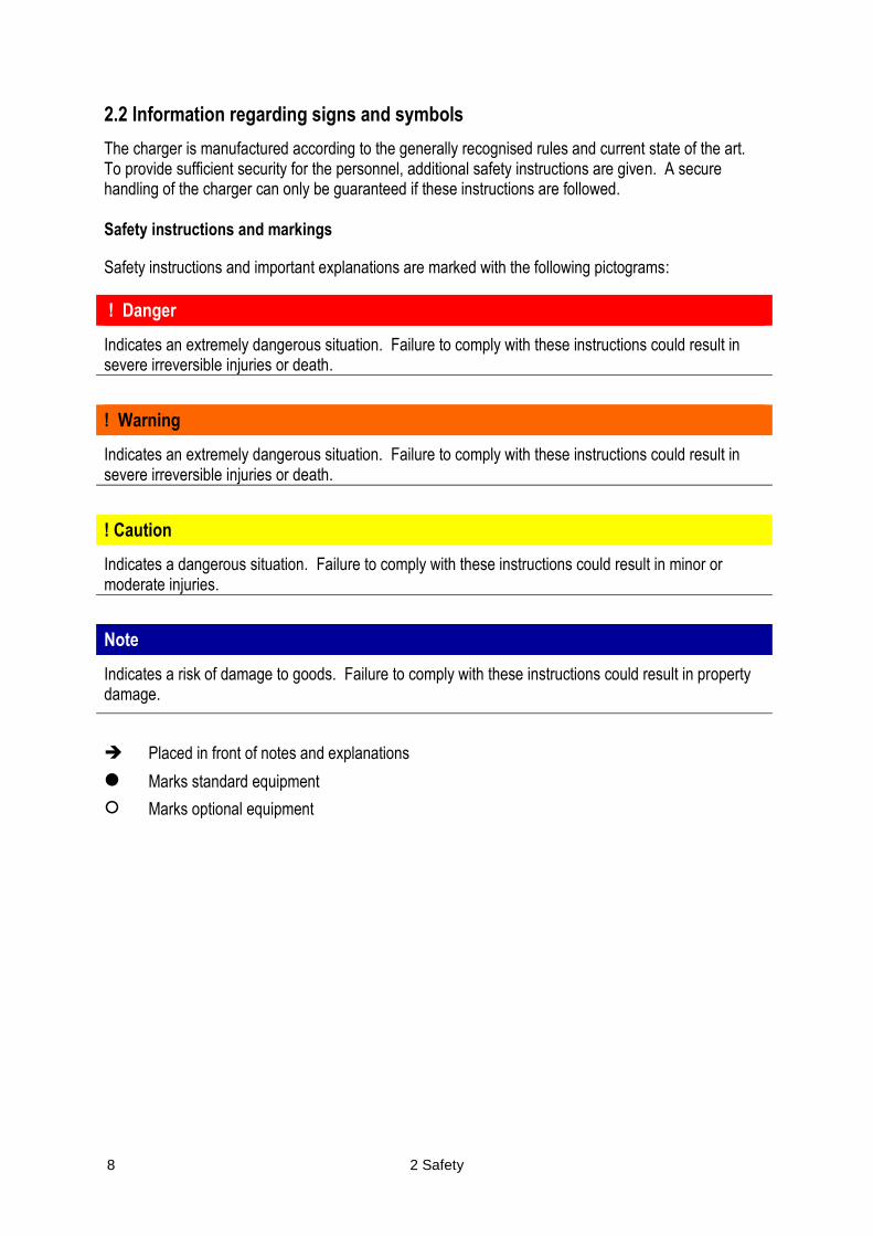
The charger is manufactured according to the generally recognised rules and current state of the art. To provide sufficient security for the personnel, additional safety instructions are given. A secure handling of the charger can only be guaranteed if these instructions are followed. Safety instructions and markings
Safety instructions and important explanations are marked with the following pictograms:
! Danger
Indicates an extremely dangerous situation. Failure to comply with these instructions could result in severe irreversible injuries or death.
! Warning
Indicates an extremely dangerous situation. Failure to comply with these instructions could result in severe irreversible injuries or death.
! Caution
Indicates a dangerous situation. Failure to comply with these instructions could result in minor or moderate injuries.
Note
Indicates a risk of damage to goods. Failure to comply with these instructions could result in property damage.
Placed in front of notes and explanations
Marks standard equipment
Marks optional equipment
2 Safety 9
2.3 Personnel qualification
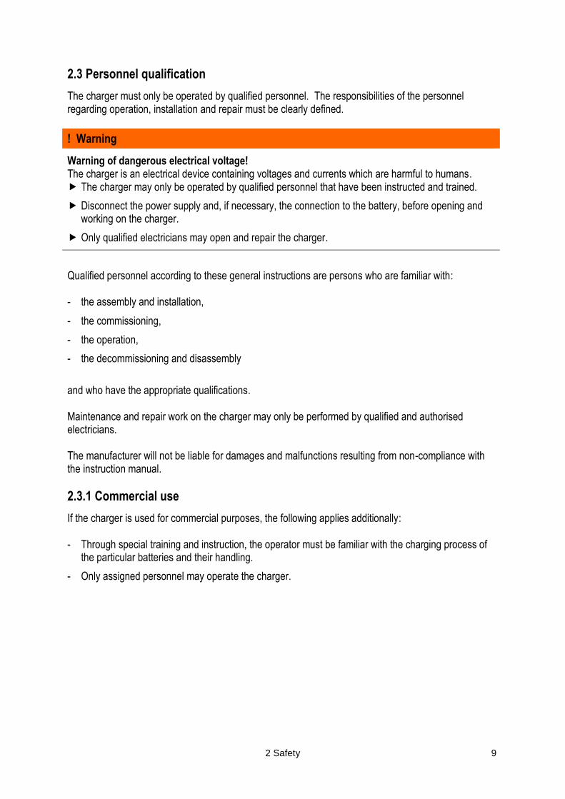
The charger must only be operated by qualified personnel. The responsibilities of the personnel regarding operation, installation and repair must be clearly defined.
! Warning
Warning of dangerous electrical voltage! The charger is an electrical device containing voltages and currents which are harmful to humans. The charger may only be operated by qualified personnel that have been instructed and trained.
Disconnect the power supply and, if necessary, the connection to the battery, before opening and working on the charger.
Only qualified electricians may open and repair the charger.
Qualified personnel according to these general instructions are persons who are familiar with: - the assembly and installation,
- the commissioning,
- the operation,
- the decommissioning and disassembly
and who have the appropriate qualifications. Maintenance and repair work on the charger may only be performed by qualified and authorised electricians. The manufacturer will not be liable for damages and malfunctions resulting from non-compliance with the instruction manual.
2.3.1 Commercial use
If the charger is used for commercial purposes, the following applies additionally: - Through special training and instruction, the operator must be familiar with the charging process of
the particular batteries and their handling.
- Only assigned personnel may operate the charger.
10 2 Safety
2.4 Intended use
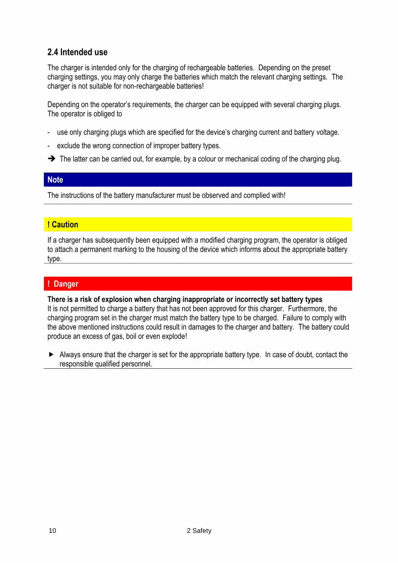
The charger is intended only for the charging of rechargeable batteries. Depending on the preset charging settings, you may only charge the batteries which match the relevant charging settings. The charger is not suitable for non-rechargeable batteries! Depending on the operator’s requirements, the charger can be equipped with several charging plugs. The operator is obliged to - use only charging plugs which are specified for the device’s charging current and battery voltage.
- exclude the wrong connection of improper battery types.
The latter can be carried out, for example, by a colour or mechanical coding of the charging plug.
Note
The instructions of the battery manufacturer must be observed and complied with!
! Caution
If a charger has subsequently been equipped with a modified charging program, the operator is obliged to attach a permanent marking to the housing of the device which informs about the appropriate battery type.
! Danger
There is a risk of explosion when charging inappropriate or incorrectly set battery types It is not permitted to charge a battery that has not been approved for this charger. Furthermore, the charging program set in the charger must match the battery type to be charged. Failure to comply with the above mentioned instructions could result in damages to the charger and battery. The battery could produce an excess of gas, boil or even explode! Always ensure that the charger is set for the appropriate battery type. In case of doubt, contact the
responsible qualified personnel.

2 Safety 11
With regard to the intended use, the data - concerning the place of use (refer to sections “Safety instructions regarding assembly and
installation” and “Requirements regarding the place of use”),
- concerning the type plate (refer to section “Markings and signs on the charger”)
- contained in the technical data (refer to appendix “Technical data”)
must be observed and complied with.
! Danger
There is a risk of severe personal injuries and property damage resulting from:
improper use or incorrect operation,
unauthorised opening of the charger,
wrong installation or improper maintenance and repair.
! Danger
Any information contained in this instruction manual regarding the intended use, residual risk (refer to section “Residual risk”), installation, operation as well as maintenance and repair must be observed and complied with.
The charger may only be used according to the applications specified in the instruction manual and technical description. It may only be operated with accessories and/or components which have been approved or recommended by the manufacturer. Any other use is considered to be improper. The operator and/or user of the charger shall be solely liable for any damages resulting from non-compliance. Commissioning of the charger is only permitted, if the guideline on electromagnetic compatibility (2004/108/CE) is complied with.

12 2 Safety
2.5 Safety instructions regarding troubleshooting, maintenance and repair
Before carrying out maintenance or repair work, the charger must be disconnected from the supply voltage and battery. No alterations, additions and modifications which could affect safety may be made to the charger without permission of the manufacturer! This also applies to the installation and adjustment of safety devices. Particular care must be taken to ensure that distances and clearances are not reduced. Used spare parts have to comply with the technical requirements determined by the manufacturer. This is always guaranteed with original spare parts.
3 Product information 13
3 Product information
3.1 Description of the product and its function
The charger is exclusively intended for charging batteries. Depending on the preset charging program, only the respective batteries may be charged. The customer-specific charging program for the respective battery type is preset at the factory. The individual components of the charger are installed in a stable steel sheet housing. The charger is connected to the mains via a power cable and plug. An integral plug for non-heating devices can be installed optionally. Charging cables can be equipped with a battery-specific charging plug for the battery connection.
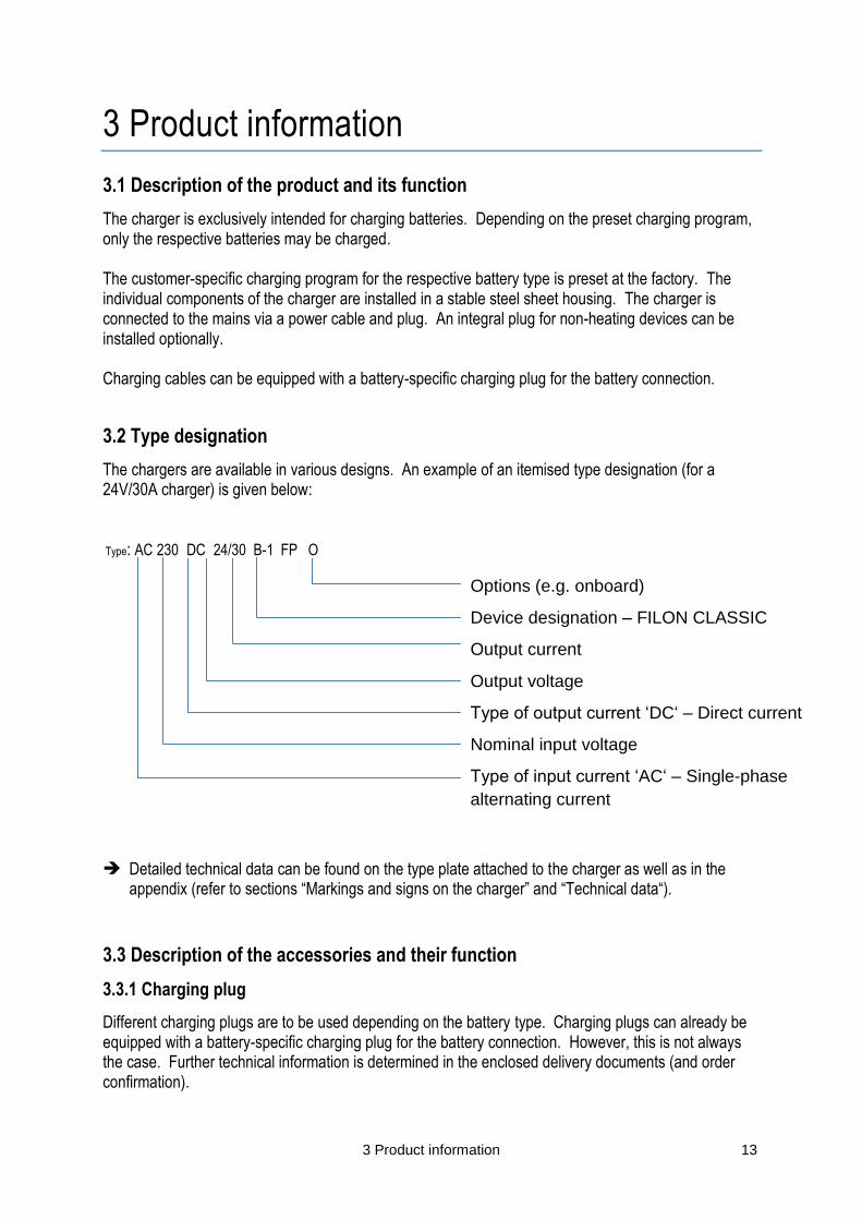
3.2 Type designation
The chargers are available in various designs. An example of an itemised type designation (for a 24V/30A charger) is given below: Type: AC 230 DC 24/30 B-1 FP O Detailed technical data can be found on the type plate attached to the charger as well as in the
appendix (refer to sections “Markings and signs on the charger” and “Technical data“).
3.3 Description of the accessories and their function
3.3.1 Charging plug
Different charging plugs are to be used depending on the battery type. Charging plugs can already be equipped with a battery-specific charging plug for the battery connection. However, this is not always the case. Further technical information is determined in the enclosed delivery documents (and order confirmation).
Options (e.g. onboard)
Device designation – FILON CLASSIC
Output current
Output voltage
Type of output current ‘DC‘ – Direct current
Nominal input voltage
Type of input current ‘AC‘ – Single-phase
alternating current
14 3 Product information
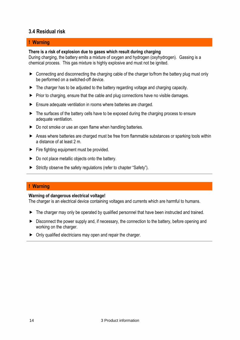
3.4 Residual risk
! Warning
There is a risk of explosion due to gases which result during charging During charging, the battery emits a mixture of oxygen and hydrogen (oxyhydrogen). Gassing is a chemical process. This gas mixture is highly explosive and must not be ignited. Connecting and disconnecting the charging cable of the charger to/from the battery plug must only
be performed on a switched-off device.
The charger has to be adjusted to the battery regarding voltage and charging capacity.
Prior to charging, ensure that the cable and plug connections have no visible damages.
Ensure adequate ventilation in rooms where batteries are charged.
The surfaces of the battery cells have to be exposed during the charging process to ensure adequate ventilation.
Do not smoke or use an open flame when handling batteries.
Areas where batteries are charged must be free from flammable substances or sparking tools within a distance of at least 2 m.
Fire fighting equipment must be provided.
Do not place metallic objects onto the battery.
Strictly observe the safety regulations (refer to chapter “Safety”).
! Warning
Warning of dangerous electrical voltage! The charger is an electrical device containing voltages and currents which are harmful to humans. The charger may only be operated by qualified personnel that have been instructed and trained.
Disconnect the power supply and, if necessary, the connection to the battery, before opening and working on the charger.
Only qualified electricians may open and repair the charger.
3 Product information 15
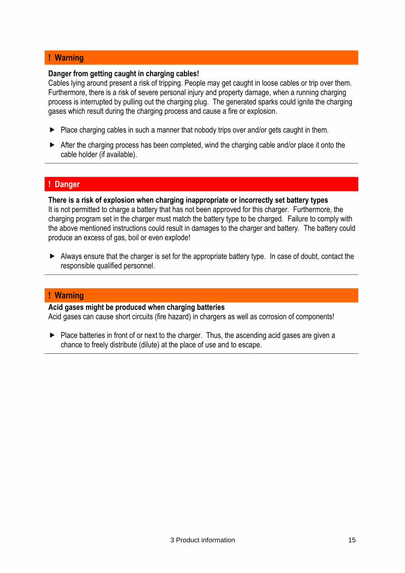
! Warning
Danger from getting caught in charging cables! Cables lying around present a risk of tripping. People may get caught in loose cables or trip over them. Furthermore, there is a risk of severe personal injury and property damage, when a running charging process is interrupted by pulling out the charging plug. The generated sparks could ignite the charging gases which result during the charging process and cause a fire or explosion. Place charging cables in such a manner that nobody trips over and/or gets caught in them.
After the charging process has been completed, wind the charging cable and/or place it onto the cable holder (if available).
! Danger
There is a risk of explosion when charging inappropriate or incorrectly set battery types It is not permitted to charge a battery that has not been approved for this charger. Furthermore, the charging program set in the charger must match the battery type to be charged. Failure to comply with the above mentioned instructions could result in damages to the charger and battery. The battery could produce an excess of gas, boil or even explode! Always ensure that the charger is set for the appropriate battery type. In case of doubt, contact the
responsible qualified personnel.
! Warning
Acid gases might be produced when charging batteries Acid gases can cause short circuits (fire hazard) in chargers as well as corrosion of components! Place batteries in front of or next to the charger. Thus, the ascending acid gases are given a
chance to freely distribute (dilute) at the place of use and to escape.

16 3 Product information
3.5 Description of the safety devices
The charger has been designed and constructed according to the recognised rules of engineering. When operated according to the intended use, there is no risk to the safety and health of the operating personnel or third parties. All electrically live components are equipped with housings or coverings which can only be removed with tools. All cables and plugs are properly shielded and/or grounded. The charger is designed according to protection class IP 21 (standard). All electric and/or electronic components bear the CE marking. The necessary insulation distances are kept. All circuits are secured with primary and secondary fuses with defined current rating and triggering characteristics. All metallic components are grounded through a protective conductor system. The charger is equipped with an automatic switch-off which is activated as soon as the preset maximum charge of the battery has been reached. This prevents overcharging as well as an excessive outgassing of explosive vapours.
3 Product information 17
3.6 Markings and signs on the charger
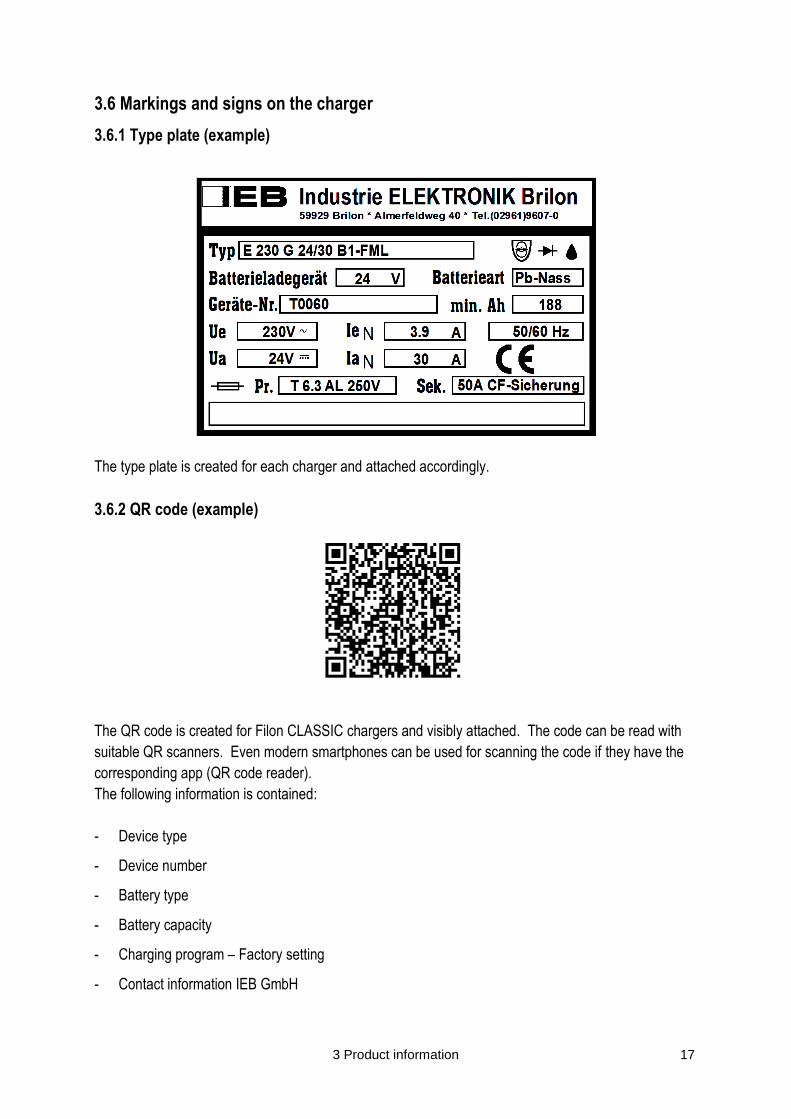
3.6.1 Type plate (example)
The type plate is created for each charger and attached accordingly.
3.6.2 QR code (example)
The QR code is created for Filon CLASSIC chargers and visibly attached. The code can be read with
suitable QR scanners. Even modern smartphones can be used for scanning the code if they have the
corresponding app (QR code reader).
The following information is contained:
- Device type
- Device number
- Battery type
- Battery capacity
- Charging program – Factory setting
- Contact information IEB GmbH

18 4 Assembly and commissioning
4 Assembly and commissioning
4.1 Safety instructions regarding assembly and installation
Make sure that no liquids enter the inside of the charger. The horizontal distance between the charger and flammable materials must be at least 2.5 m. It is not permitted to store flammable materials, e. g. on shelves, or use flammable building materials above the charger. The distance to areas exposed to fire and explosion risks as well as to potentially explosive materials must be at least 5.0 m. Protect the charger from inadmissible load. Ensure that no components get damaged, particularly during transport and handling. Avoid touching electronic components. The charger contains electrostatically sensitive components which can easily be damaged due to improper handling. Ensure that electric components are not mechanically damaged or destroyed. The electrical installation (cable cross-sections, fuse protections, protective conductor connection) must be carried out in accordance with the relevant regulations. Prior to the electrical installation, compare the performance data mentioned on the type plate with the performance data of the supply connections. Observe the power supply data stated on the type plate (voltage and frequency). Refer to section “Connecting the charger to the power supply“.

4 Assembly and commissioning 19
4.2 Scope of delivery
Note
Before commencing installation, compare the scope of delivery with the delivery documents to verify completeness. In case of any defects, contact the manufacturer immediately.
Delivery comprises at least the following parts: - charger with preset charging program,
- connected power and battery cables,
- instruction manual
- and delivery note.
The scope of delivery as well as the charger model may vary depending on the customer requirements. Further technical data can be found in the enclosed delivery documents (as well as in the order confirmation). Proceeding • Immediately after delivery, check whether the product has been delivered completely and
undamaged.
• Ensure that the data stated on the delivery note matches the data on the type plate.
• In case of defects, immediately contact the manufacturer and, if necessary, the transport company.
• Check, if the charger has unfastened screw connections etc. If necessary, fasten those connections again.
4.3 Requirements regarding the place of use
The charger may only be operated in closed, frost-free and dry rooms. The ambient temperatures at the place of installation may not fall below 0°C and not exceed 40°C. The place of use may not be subject to excessive dust exposure. Ensure that there are no conductive dusts (soot, metals). The place of use requires sufficient ventilation so that resulting charging gases (e.g. acid vapours, oxyhydrogen) are given a chance to distribute (dilute) and explosive gas mixtures are securely prevented. The place of installation has to be selected in such a manner that ventilation openings are not covered and the cooling air is not hindered. Do not place the charger next to radiators or other heat sources. Heat accumulation, caused e. g. through blocked ventilation slots, must be excluded.

20 4 Assembly and commissioning
4.4 Assembly / Installation of the charger and placing the battery
! Warning
There is a risk of explosion due to gases which result during charging During charging, the battery emits a mixture of oxygen and hydrogen (oxyhydrogen). Gassing is a chemical process. This gas mixture is highly explosive and must not be ignited.
Connecting and disconnecting the charging cable of the charger to/from the battery plug must only be performed on a switched-off device.
The charger has to be adjusted to the battery regarding voltage and charging capacity.
Prior to charging, ensure that the cable and plug connections have no visible damages.
Ensure adequate ventilation in rooms where batteries are charged.
The surfaces of the battery cells have to be exposed during the charging process to ensure adequate ventilation.
Do not smoke or use an open flame when handling batteries.
Areas where batteries are charged must be free from flammable substances or sparking tools within a distance of at least 2.5 m.
Fire fighting equipment must be provided.
Do not place metallic objects onto the battery.
Strictly observe the safety regulations (refer to chapter “Safety”).
During the assembly/installation of the charger, the following points are to be observed: Proceeding • Use the provided wall fixing material (if included in the scope of delivery) for fixing the charger to the
wall. The drilling pattern is enclosed in the appendix (see dimension and section drawing).
• Ensure optimal ventilation of the charger.
• The lateral distance to the next charger must be at least the double width of the charger.
A staggered arrangement of the chargers is necessary, if this distance cannot be kept.
• Keep a distance of at least 0.5 m to adjoining walls.

4 Assembly and commissioning 21
! Warning
Acid gases might be produced when charging batteries.
Acid gases can cause short circuits (fire hazard) in chargers as well as corrosion of components! Always place batteries next to the charger. Thus, the ascending acid gases are given a chance to
freely distribute (dilute) at the place of use and to escape.
During the assembly/installation of the charger, ensure that: • no aggressive gases, e. g. acid gases, are produced,
• there are no conductive dusts, e. g. soot or metal dusts,
• there is no excessively high exposure of non-conductive dusts,
• no liquids enter the inside of the charger.
• Assemble/install the charger in such a manner that the connection to the supply network is within reach of the charger cable (at least 2m).
! Caution
The power cable of the charger must not be extended.
Placing the battery to be charged Proceeding • Place the battery in front of or next to the charger, so that the plug of the battery is within reach of
the charger’s charging cable (standard 2 m).
! Caution
The charging cable of the charger must not be extended.

22 4 Assembly and commissioning
4.5 Mains connection and fuses
! Warning
Warning of dangerous electrical voltage!
The charger may only be operated by qualified personnel that have been instructed and trained.
Disconnect the power supply and, if necessary, the connection to the battery, before opening and working on the charger.
Only qualified electricians may open and repair the charger.
A mains connection is required at the intended place of use for operating the charger. Mains voltage and frequency need to match the data stated on the type plate (refer to section “Markings and signs on the charger”). The mains connection must be properly grounded.
4 Assembly and commissioning 23
4.6 Connecting the charger to the supply network
Note
Before connecting the charger to the supply network, observe the following sections of chapter “4 Installation and commissioning”:
„Safety information regarding assembly and installation“
„Assembly / Installation of the charger and placing the battery“
„Requirements regarding the place of use“
„Mains connection and fuses“
! Caution
The power cable of the charger must not be extended.
- Place the battery in front of or next to the charger, so that the plug of the battery is within reach of the charger’s charging cable (standard 2.5 m).
Note
All chargers are supplied with transformer connection mains voltage 230V/400V and have a +6% / -6%; -10% connectivity. During commissioning is essential to ensure that the transformer connection matches the mains voltage. Does the supply voltage not match with the settings, the charger may be damaged See 4.7 Transformer tapping
24 4 Assembly and commissioning
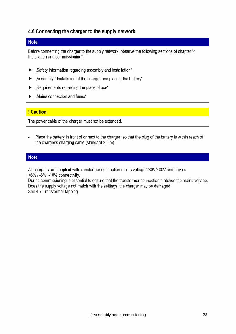
4.7 Transformer tapping
The charger must be adjusted to the supply network available at the place of use. The following images illustrate tapping.
4.7.1 Wa single-phase
+- 0% 230V
+6% 244V
4 Assembly and commissioning 25
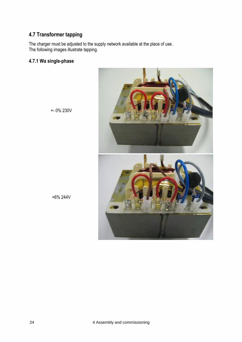
+10% 253V
-6% 216V
-10% 207V

26 4 Assembly and commissioning
4.7.2 Wa three-phase current
+- 0% 400V
+6% 424V
-6% 376V

4 Assembly and commissioning 27
-10% 360V
4.7.3 Wa-Pulse single-phase
+-0% 230V
Low capacity
+-0% 230V
High capacity
28 4 Assembly and commissioning
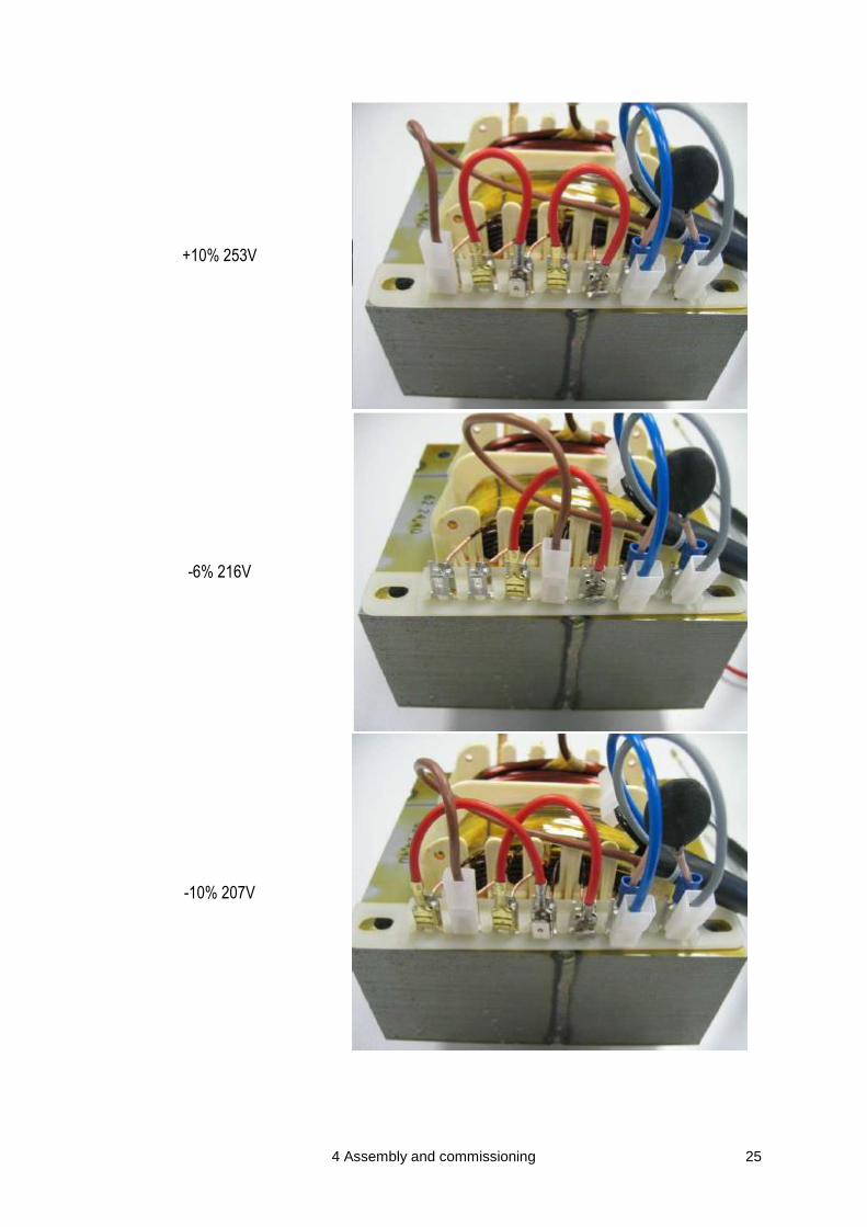
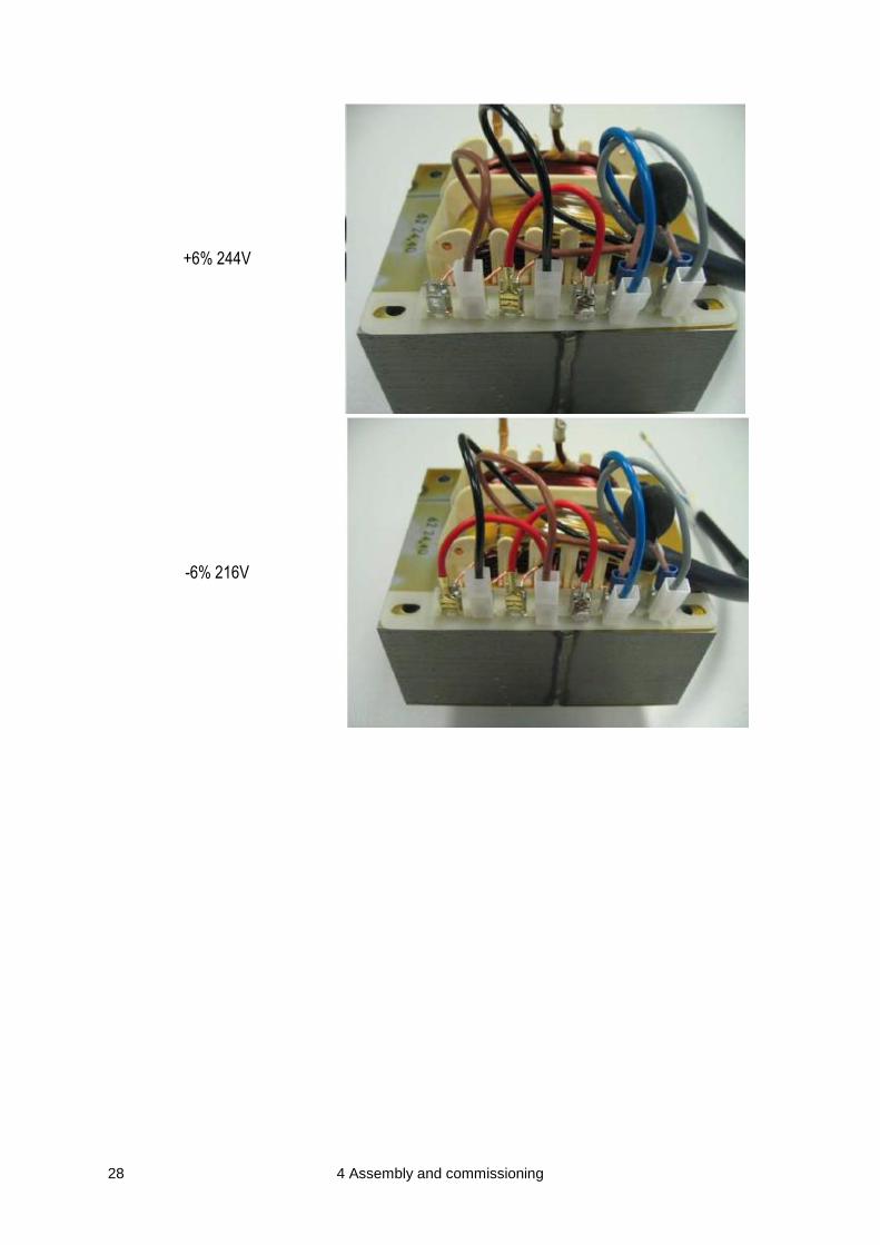
+6% 244V
-6% 216V
4 Assembly and commissioning 29
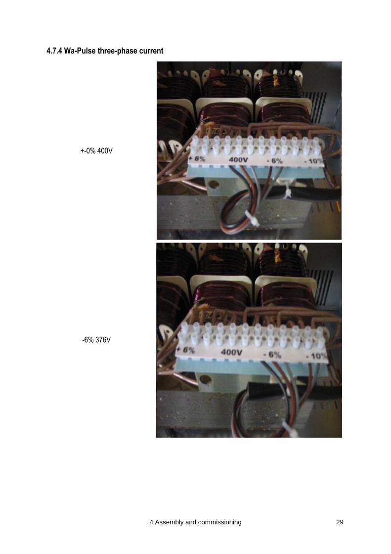
4.7.4 Wa-Pulse three-phase current
+-0% 400V
-6% 376V
30 4 Assembly and commissioning
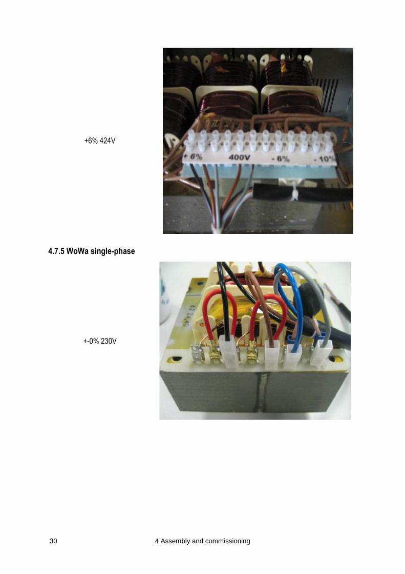
+6% 424V
4.7.5 WoWa single-phase
+-0% 230V
4 Assembly and commissioning 31
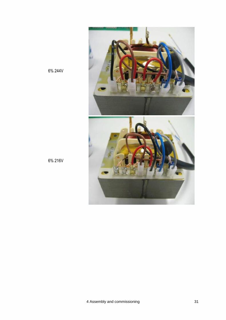
6% 244V
6% 216V
32 4 Assembly and commissioning
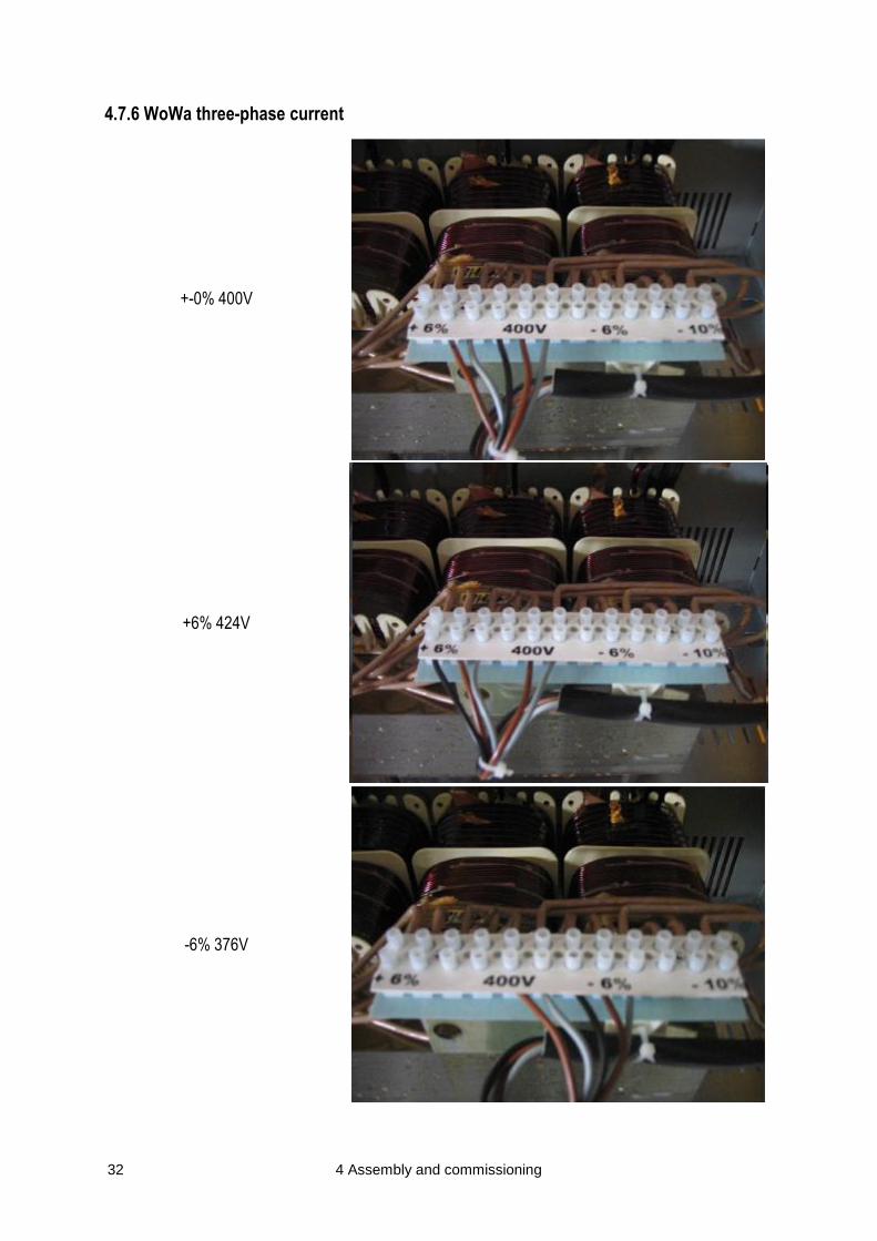
4.7.6 WoWa three-phase current
+-0% 400V
+6% 424V
-6% 376V

4 Assembly and commissioning 33
-10% 360V
4.8 Initial commissioning and functional test
After the charger has been properly assembled and installed, it needs to be put into operation for the first time in order to perform a functional test (see chapter “Operation“).

34 5 Operation
5 Operation
5.1 Operating instructions for the IUIa battery charger
5.1.1 Functional description and charge monitoring
After the charger has been switched on, a functional test of the charging electronics and the battery and mains connection is carried out for 5 seconds. If the charger has been properly connected, the main charge switches on (l-constant). The LED “HL” is lit. Once the set gassing voltage has been achieved (e. g. 2.4 V/cell in case of lead-acid batteries which require low maintenance), it is kept constantly and the current slowly drops (U-constant). As soon as the current has reached the size of the gassing current, the electronics switch to recharge. The LED “HL” switches off and the LED “NL” lights up. During recharge, the battery is fully charged to 100%. After the recharge has been completed, the charging electronics switch to charge stop. The LED “NL” switches off and the LED “LE” is lit. After the tLEP pause time and depending on its specifications, the device will perform either a one-time compensation charging or charge retention. The LED “LE” is constantly lit. For customer-specific charge retention, please refer to the characteristic table.
5.1.2 Signalling and operating state
The present operating state is indicated by 4 LEDs.
LED Colour Continuous light Flashing Quick flashing Alternate flashing
1
Main charge Yellow Main charge
Main charge U<1.75V/cell Pb
Functional testing LED1 and LED4
Error: main charging time
2
Recharge Yellow Recharge
Compensation
charging
LED2 and LED4
Error: recharging time
3
Charge stop Green Charge stop Charge retention
LED3 and LED4
Error: charging time
4
Failure Red
No battery or wrong
battery
U < 1.75V/cell
L-> operating error
S-> system error ---
LED1,2 and 3 alternating
with LED4
L = slow, approx. 1 time per second; S = fast, approx. 3 times per second
5.1.3 Operating errors (error 2-23)
Errors which are caused by the user and connected battery! - Battery connection with switched poles / interrupted
- Overcharge The capacity charged during the main charge is greater than 110% of the rated capacity. The overall capacity charged during main charge and recharge is greater than 135% of the rated capacity.
- U-phase too long
- I-phase too long (approx. 110% of rated capacity)
- Maximum main charging time exceeded
5 Operation 35
5.1.4 System errors (errors 24-99)
Errors which are caused by defects within the charging system! After troubleshooting, all occurring errors can be deleted by disconnecting battery and mains. (RESET) If the LED “Failure” flashes, wait for 10 minutes before switching on the device.
5.1.5 Safety function of the electronic charging switch
1. If the battery voltage is lower than 1.75 V/cell, the LED „HL“ flashes. It is necessary to check if a deeply discharged or wrong battery has been connected. Rated current flows.
2. If recharge is not reached during the main charging time, the charging switch stops the charge. A defective or deeply discharged battery may have been connected. The LED “Failure” flashes.
3. If the battery connection is interrupted or carried out with switched poles, the charging switch turns off. The LED “Failure” is lit.
5.2 Operating instructions for the Wa / WoWa / EC / Pulse / Aquamatik battery
chargers
5.2.1 Functional description and charge monitoring
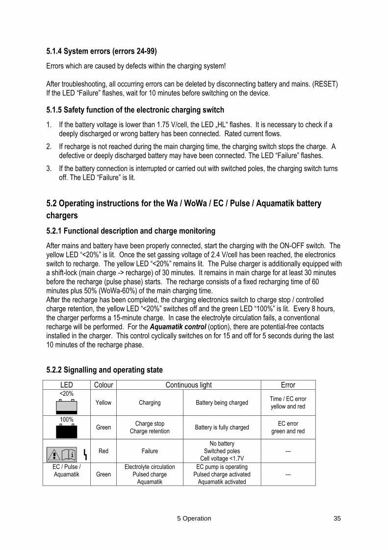
After mains and battery have been properly connected, start the charging with the ON-OFF switch. The yellow LED “<20%” is lit. Once the set gassing voltage of 2.4 V/cell has been reached, the electronics switch to recharge. The yellow LED “<20%” remains lit. The Pulse charger is additionally equipped with a shift-lock (main charge -> recharge) of 30 minutes. It remains in main charge for at least 30 minutes before the recharge (pulse phase) starts. The recharge consists of a fixed recharging time of 60 minutes plus 50% (WoWa-60%) of the main charging time. After the recharge has been completed, the charging electronics switch to charge stop / controlled charge retention, the yellow LED “<20%” switches off and the green LED “100%” is lit. Every 8 hours, the charger performs a 15-minute charge. In case the electrolyte circulation fails, a conventional recharge will be performed. For the Aquamatik control (option), there are potential-free contacts installed in the charger. This control cyclically switches on for 15 and off for 5 seconds during the last 10 minutes of the recharge phase.
5.2.2 Signalling and operating state
LED Colour Continuous light Error <20%
Yellow Charging Battery being charged Time / EC error yellow and red
100%
Green Charge stop
Charge retention Battery is fully charged
EC error green and red
Red Failure No battery
Switched poles Cell voltage <1.7V
---
EC / Pulse / Aquamatik Green
Electrolyte circulation Pulsed charge
Aquamatik
EC pump is operating Pulsed charge activated
Aquamatik activated ---

36 5 Operation
5.2.3 Safety function of the electronic charging switch
- Charging process does not exceed 16h (12h main charge + 4h recharge)
- Safety shutdown after 12h of main charge (HL) – the red and yellow LEDs are lit
- Switching to charge stop not later than after 4h of recharge (NL)
- Standard cyclical charge retention – pause after 8 hours – switched on for 15 minutes
- Power consumption of charger in charge stop and standby 1.5V
- Restart charge without power switch or any other power interruption solely by connecting the battery.
- Without battery, the charger output is immediately free of voltage.
- Switching from HL (main charge) to NL (recharge) with 2.42 V/cell
- Protection against reversed polarity by fuse. Change fuse after polarity error.
5.3 Visual inspection prior to commissioning
Prior to each charging, ensure that - the mains connection is undamaged,
- the housing does not show any damages,
- the insulation of the charging and power cables is undamaged,
- the charging plug is undamaged,
- all exterior screw connections are fastened.
5 Operation 37
5.4 Activities prior to charging
! Warning
Warning of dangerous electrical voltage! The charger is an electrical device containing voltages and currents which are harmful to humans. The charger may only be operated by qualified personnel that have been instructed and trained.
Disconnect the power supply and, if necessary, the connection to the battery, before opening and working on the charger.
Only qualified electricians may open and repair the charger.
The charging process of a battery normally involves the following steps for the instructed operator:
Proceeding
• Ensure that charger and battery type match,
• Check the charger for damages (refer to section “Visual inspection prior to commissioning”).
• Connect the battery to the charger.
• Connect the charger to the mains.
• Charging process starts automatically.
• Charging process ends automatically.
• Disconnect the charger from the mains.
• Disconnect the battery from the charger.
The following sections provide more detailed information regarding the individual operating steps.
These sections must be read carefully prior to the first operation of the charger.
38 5 Operation
5.5 Device options (o)
5.5.1 Charging process with electrolyte circulation (o)
Note
If the EC pump is switched on, the blue LED „AIR“ on the operating and display unit is lit. The proper operation of the electrolyte circulation (EC) is monitored with a potential-free pressure switch in the pump housing. If the charger detects a pressure drop during charging, the charging process will be continued with the charge factor 1.20. The blue LED “AIR” on the operating and display unit flashes. The respective operating state remains lit. The battery will be charged with the original charge factor, if the pressure drop has been rectified within the first hour. The EC pump must not be operated without counter-pressure.
Install the charger in such a manner that the built-in EC pump is placed at a distance of at least
0.5 m over the battery to be charged.
If an error message occurs (blue LED „AIR“ flashes), fully charge the battery without electrolyte circulation. Early interrupting may lead to an insufficient charge state. The available battery capacity is thereby reduced.
A restart is only performed after the battery has been disconnected.
5.5.2 Start-up block (o)
Onboard devices are equipped with a start-up lock. Here, the charger is connected to the automotive
electronics. The electric vehicle is disabled as long as the charger is connected to the supply voltage.
The start-up block is a potential-free alternating contact (max. 42V 5A), which is conducted on a three-
pole terminal strip.
! Warning
Warning of dangerous electrical voltage! There is a risk of serious damage or injury, if thestart-up block is wired improper.
5.5.3 Charging process with temperature compensation (o)
If a charging process is performed with temperature compensation, the battery temperature is measured
by means of an external temperature sensor. The charger adjusts the charging voltage (U1) to the
measured temperature.
5.5.4 External charging indicator (traffic light display) (o)
For a better and quicker visibility of the charging state from a larger distance, an external traffic light display with 360° allround signalling can be connected to the charger. The display is identical with the LED charger display.

5 Operation 39
5.5.5 Aquamatik (o)
The „Aquamatik“ option of the FILON CLASSIC charger is used to trigger an automatic water refilling system. The water refilling system is used for the automatic adjusting of the nominal electrolyte level. The charging gases escape through the degassing opening of the plugs. The valve inside the plug in connection with a floater and float linkage triggers the refill process with regard to the required water amount. The water pressure on the valve shuts the water supply off and ensures safe closing of the valve.
The automatic water refilling system can be triggered in several ways. Triggering via:
- a potential-free contact
- a 230V AC voltage
- a 12V AC voltage
Note
Connection pressure / falling water The water refilling system must be operated in such a manner that the water pressure inside the water pipe is between 0.3 to 1.8 bar. The installation height of the storage tank depends on the used water refilling system.
Triggering via:
Immersion pump:
The immersion pump generates the required filling pressure. The storage tank and battery must be placed without difference in height.
Valves without immersion pump:
In order to achieve the necessary filling pressure, the lower edge of the storage tank must be at least 3 cm above the upper edge of the battery.

40 6 Maintenance and repair
Operation of the automatic water refilling system
Conditions
- The battery is connected to the automatic “Aquamatik“ water refilling system
- The charger is equipped with the “Aquamatik” option
- The charger is connected to the battery
- The charging process has been started
Proceeding
• 10 minutes before the recharge stops, a relay contact for triggering the automatic water refilling system is cyclically triggered in the following interval:
• switched on for 15 seconds -> water supply to the battery opened
• switched off for 5 seconds -> water supply to the battery closed

6 Maintenance and repair 41
6 Maintenance and repair
6.1 Cleaning, inspection and maintenance
! Warning
Warning of dangerous electrical voltage! The charger is an electrical device containing voltages and currents which are harmful to humans.
The charger may only be operated by qualified personnel that have been instructed and trained.
Disconnect the power supply and, if necessary, the connection to the battery, before opening and working on the charger.
Only qualified electricians may open and repair the charger.
! Warning
The general operating conditions of a charger considerably affect the wear and tear of the maintenance components. The stated maintenance intervals apply to normal working conditions.
In case of increased requirements (e. g. high dust incidence or strongly fluctuating temperatures), the intervals have to be shortened suitably. In case of doubt, contact the responsible qualified personnel.
Note
Some chargers are forced-air cooled by means of a fan. As a result, dust can enter the inside of the chargers. The stated maintenance intervals apply to normal working conditions.
The installation room of the charger must be ventilated.
The installation room of the charger must be kept clean.
Check the charger for inner contamination and clean it at least every six months. Only qualified electricians must carry out works inside the charger.
In case of increased requirements (e. g. high dust incidence or strongly fluctuating temperatures), the intervals have to be shortened suitably. In case of doubt, contact the responsible qualified personnel.

42 7 Disposal
Prior to each charging, ensure that: - the mains connection is undamaged,
- the housing does not show any damages,
- the insulation of the charging and power cables is undamaged,
- the charging plug is undamaged,
- all screw connections are fastened.
! Warning
A damaged or otherwise defective charger may cause accidents If the charger and/or its performance show safety-relevant modifications, damages or other defects, do not use the charger until it has been properly repaired.
Detected defects must be reported to the superior immediately.
The defective charger must be marked and decommissioned.
Do not use the charger until the defect has been localised and rectified.
6.2 Spare parts
If you require spare parts, contact the manufacturer or supplier and provide the charger data stated on the type plate.
8 Appendix 43
7 Disposal
If the charger is definitively decommissioned, the applicable laws and regulations regarding disposal are to be observed. Detailed information can be provided by the specialised waste management companies or competent authorities. HI
Note
Electronic waste represents a high hazard potential for the environment due to its plastic, metal and heavy metal components.
Electronic waste must be disposed of and collected separately from household or commercial waste
Supply electronic waste to the internal waste management (if any), which assumes the forwarding to specialised companies (specialised waste management companies).
The packaging of the charger must be disposed of separately. Paper, cardboard and plastics must be recycled.

44 8 Appendix
8 Appendix
8.1 Charging plug
8.1.1 MICOMP Light IEB 601 charging plug for Wa / W0Wa chargers
Voltage settings
SJ „12“ 12 volt
SJ2 „24“ 24 volt
SJ3 „36“ 36 volt
SJ4 „48“ 48 volt
SJ5 „80“ 80 volt
The corresponding jumper must be set. SJ6 MODE 0
Closed: Wa
Open: WoWa
JP1 Test (Only to be used by the manufacturer) Open: Normal operation Closed: Adjust voltage

8 Appendix 45
8.1.2 MICOMP Light IEB 602 charging plug for Wa / W0Wa chargers with options (EC,
Aquamatik, Pulse, etc.)
Voltage settings
SJ „12“ 12 volt
SJ2 „24“ 24 volt
SJ3 „36“ 36 volt
SJ4 „48“ 48 volt
SJ5 „80“ 80 volt
The corresponding jumper must be set.
SJ6 MODE 0
Closed: Wa
Open: WoWa
JP2 MODE 1 (Only to be used by the manufacturer)
A B
Open Open Normal operation
Open Closed Speeded up expiration of time
Closed Open Adjust current
Closed Closed Adjust voltage
JP2 MODE 1 (Only to be used by the manufacturer)
A B
Open Open Normal operation / Aquamatik
Open Closed EC Hoppecke
Closed Open EC Deta
Closed Closed Pulse characteristic

46 8 Appendix
8.1.3 MICOMP Light IEB 601_1-3 charging plug for Wa / W0Wa chargers
Voltage settings
SJ „12“ 12 volt
SJ2 „24“ 24 volt
SJ3 „36“ 36 volt
SJ4 „48“ 48 volt
SJ5 „80“ 80 volt
The corresponding jumper must be set.
SJ6 MODE 0
Closed: Wa
Open: WoWa
JP1 Test (Only to be used by the manufacturer) Open: Normal operation Closed: Adjust voltage

8 Appendix 47
8.1.4 MICOMP Light IEB 602_1-2 charging plug for Wa / W0Wa chargers with options (EC,
Aquamatik, Pulse, etc.)
Voltage settings
SJ „12“ 12 volt
SJ2 „24“ 24 volt
SJ3 „36“ 36 volt
SJ4 „48“ 48 volt
SJ5 „80“ 80 volt
The corresponding jumper must be set.
SJ6 MODE 0
Closed: Wa
Open: WoWa
JP2 MODE 1 (Only to be used by the manufacturer)
A B
Open Open Normal operation
Open Closed Speeded up expiration of time
Closed Open Adjust current
Closed Closed Adjust voltage
MODE 2
A (SJ10) B (SJ9)
Open Open Normal operation / Aquamatik
Open Closed EC Hoppecke
Closed Open EC Deta
Closed Closed Pulse characteristic
48 8 Appendix
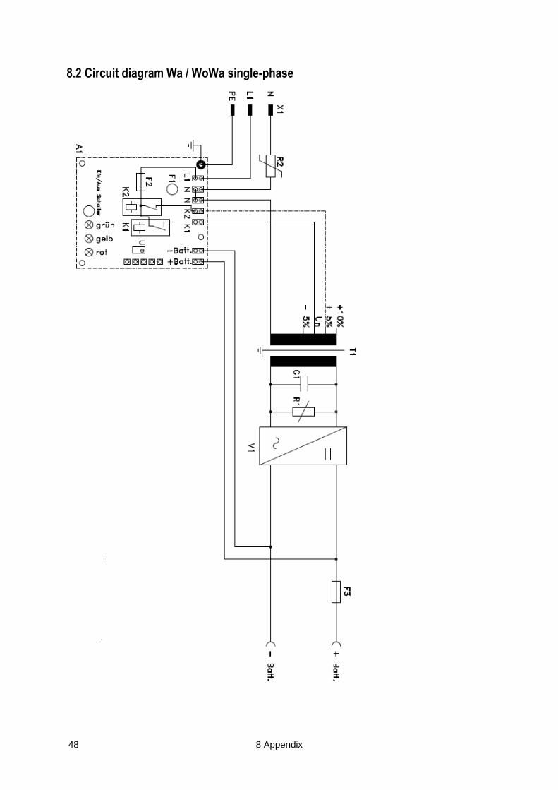
8.2 Circuit diagram Wa / WoWa single-phase
8 Appendix 49
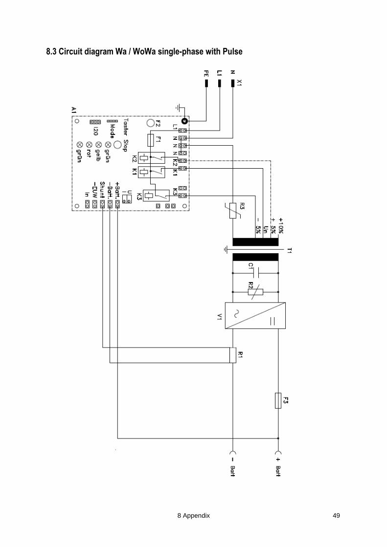
8.3 Circuit diagram Wa / WoWa single-phase with Pulse

50 8 Appendix
8.4 Circuit diagram Wa / WoWa single-phase with EC
8 Appendix 51
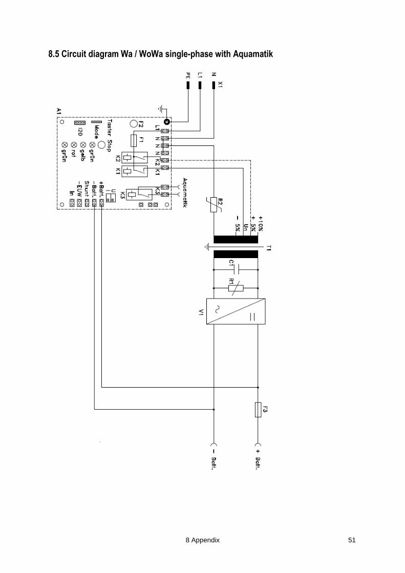
8.5 Circuit diagram Wa / WoWa single-phase with Aquamatik
52 8 Appendix
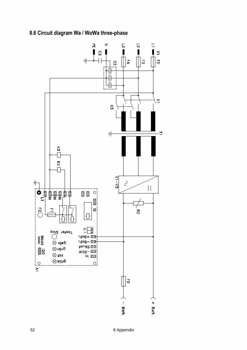
8.6 Circuit diagram Wa / WoWa three-phase

9 Technical data - Standards 53
9 Technical data - Standards
Device series FILON CLASSIC
Device no. see type plate
Charging characteristic see technical data
Temperature range 0 - 40°C
Rated input frequency 47 – 63Hz
Protection class see technical data
Housing see dimension and section drawing
Standards 2006/95/EC – Low Voltage Directive
2004/108/EEC – EMC directive
EN 60335-1 – Safety of household and similar electrical appliances
EN 60335-2-29 – Safety of household and similar electrical appliances - Particular requirements for battery chargers
EN 61558 – Transformers
EN 60146 – Semiconductor converters
EN 61000-6-2 and EN 61000-6-3 – EMC
EN 61000-3-2 – Circuit feedback
EN 61000-3-3 – Voltage fluctuations and flicker
EN 61000-4-2 – ESD
EN 61000-4-3 – Influence of electromagnetic fields
EN 61000-4-4 – Burst
EN 61000-4-5 – Surge
EN 61000-4-6 – Conducted interferences induced by HF fields EN 61000-4-11 – Voltage dips, short interruptions and voltage variations immunity
EN 60068-2-6 – Vibration sinusoidal
EN 60068-2-27 – Semi-sinusoidal shock
DIN VDE 0701/0702 – Inspection of electrical appliances
EN50178 – Equipment of power installations with electrical components

54 9 Technical data - Standards

9 Technical data - Standards 55
Industrie
Elektronik
Brilon GmbH
Almerfeldweg 40 59929 Brilon, Germany
Ph.: +49 2961/9607-0
Fax: +49 2961/9607-77
www.ieb.de – [email protected]