instruction manual: fieldvue dvc2000 digital valve controller · fisher™ fieldvue™ dvc2000...
TRANSCRIPT
www.Fisher.com
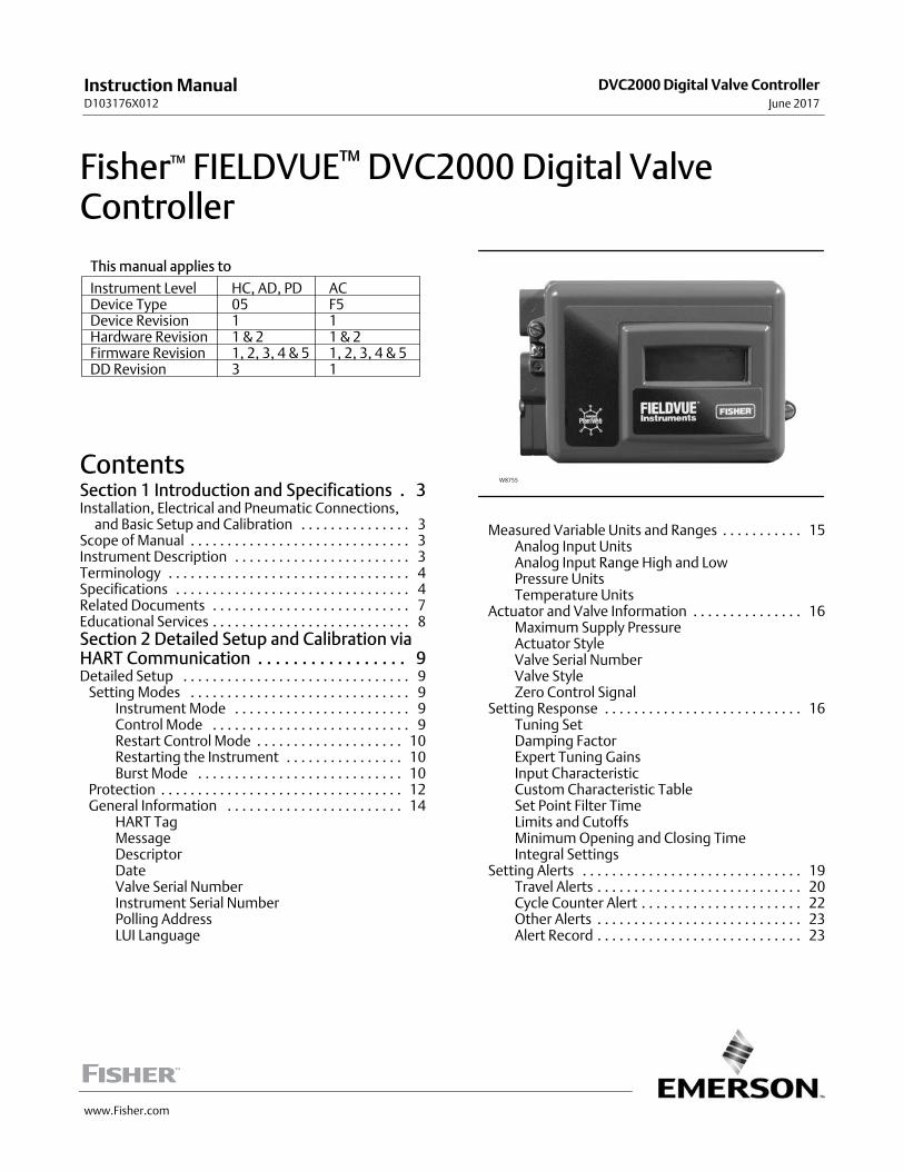
Fisher™ FIELDVUE™ DVC2000 Digital ValveController
This manual applies to
Instrument Level HC, AD, PD ACDevice Type 05 F5Device Revision 1 1Hardware Revision 1 & 2 1 & 2Firmware Revision 1, 2, 3, 4 & 5 1, 2, 3, 4 & 5DD Revision 3 1
ContentsSection 1 Introduction and Specifications 3.Installation, Electrical and Pneumatic Connections,�and Basic Setup and Calibration 3. . . . . . . . . . . . . . .Scope of Manual 3. . . . . . . . . . . . . . . . . . . . . . . . . . . . . .Instrument Description 3. . . . . . . . . . . . . . . . . . . . . . . .Terminology 4. . . . . . . . . . . . . . . . . . . . . . . . . . . . . . . . .Specifications 4. . . . . . . . . . . . . . . . . . . . . . . . . . . . . . . .Related Documents 7. . . . . . . . . . . . . . . . . . . . . . . . . . .Educational Services 8. . . . . . . . . . . . . . . . . . . . . . . . . . .Section 2 Detailed Setup and Calibration viaHART Communication 9. . . . . . . . . . . . . . . . .Detailed Setup 9. . . . . . . . . . . . . . . . . . . . . . . . . . . . . . .
Setting Modes 9. . . . . . . . . . . . . . . . . . . . . . . . . . . . . .Instrument Mode 9. . . . . . . . . . . . . . . . . . . . . . . .Control Mode 9. . . . . . . . . . . . . . . . . . . . . . . . . . .Restart Control Mode 10. . . . . . . . . . . . . . . . . . . .Restarting the Instrument 10. . . . . . . . . . . . . . . .Burst Mode 10. . . . . . . . . . . . . . . . . . . . . . . . . . . .
Protection 12. . . . . . . . . . . . . . . . . . . . . . . . . . . . . . . . .General Information 14. . . . . . . . . . . . . . . . . . . . . . . .
HART TagMessageDescriptorDateValve Serial NumberInstrument Serial NumberPolling AddressLUI Language
W8755
Measured Variable Units and Ranges 15. . . . . . . . . . .Analog Input UnitsAnalog Input Range High and LowPressure UnitsTemperature Units
Actuator and Valve Information 16. . . . . . . . . . . . . . .Maximum Supply PressureActuator StyleValve Serial NumberValve StyleZero Control Signal
Setting Response 16. . . . . . . . . . . . . . . . . . . . . . . . . . .Tuning SetDamping FactorExpert Tuning GainsInput CharacteristicCustom Characteristic TableSet Point Filter TimeLimits and CutoffsMinimum Opening and Closing TimeIntegral Settings
Setting Alerts 19. . . . . . . . . . . . . . . . . . . . . . . . . . . . . .Travel Alerts 20. . . . . . . . . . . . . . . . . . . . . . . . . . . .Cycle Counter Alert 22. . . . . . . . . . . . . . . . . . . . . .Other Alerts 23. . . . . . . . . . . . . . . . . . . . . . . . . . . .Alert Record 23. . . . . . . . . . . . . . . . . . . . . . . . . . . .
Instruction ManualD103176X012
DVC2000 Digital Valve ControllerJune 2017
Instruction ManualD103176X012
DVC2000 Digital Valve ControllerJune 2017
2
Self-Test Failure for Instrument Shutdown 24. . . . . .Transmitter/Switches 25. . . . . . . . . . . . . . . . . . . . . . .
Tuning 26. . . . . . . . . . . . . . . . . . . . . . . . . . . . . . . . . . . . .Automatic 26. . . . . . . . . . . . . . . . . . . . . . . . . . . . . . . . .Manual 26. . . . . . . . . . . . . . . . . . . . . . . . . . . . . . . . . . .
Calibration 27. . . . . . . . . . . . . . . . . . . . . . . . . . . . . . . . . .Analog Input Calibration 27. . . . . . . . . . . . . . . . . . . . .
Using the Field Communicator 27. . . . . . . . . . . .Using Local Operator Interface 28. . . . . . . . . . . .
Auto Calibrate Travel 28. . . . . . . . . . . . . . . . . . . . . . . .Manual Calibrate Travel 29. . . . . . . . . . . . . . . . . . . . . .
Analog Calibration Adjust 29. . . . . . . . . . . . . . . .Digital Calibration Adjust 29. . . . . . . . . . . . . . . . .
Pressure Sensor Calibration 30. . . . . . . . . . . . . . . . . .Output Pressure Sensor 30. . . . . . . . . . . . . . . . . .
Position Transmitter 31. . . . . . . . . . . . . . . . . . . . . . . .
Section 3 Viewing Device Variables andDiagnostics 33. . . . . . . . . . . . . . . . . . . . . . . . .Viewing Variables 33. . . . . . . . . . . . . . . . . . . . . . . . . . . .
Analog Input, Travel, Valve Set Point, Drive Signaland Output Pressure 33. . . . . . . . . . . . . . . . . . . . . .
Additional Instrument Variables 33. . . . . . . . . . . . . . .Viewing Device Information 34. . . . . . . . . . . . . . . . . . .Viewing Instrument Status 35. . . . . . . . . . . . . . . . . . . .
Section 4 Maintenance and Troubleshooting 39. . . . . . . . . . . . . . . . . . . . .Stroking the Digital Valve Controller Output 39. . . . . .Replacing the Instrument 40. . . . . . . . . . . . . . . . . . . . .Replacing the Magnetic Feedback Assembly 41. . . . . .Component Replacement 41. . . . . . . . . . . . . . . . . . . . .
Replacing the I/P Converter 41. . . . . . . . . . . . . . . . . .Replacing the Pneumatic Relay 43. . . . . . . . . . . . . . .
Troubleshooting 44. . . . . . . . . . . . . . . . . . . . . . . . . . . . .Checking Available Voltage 46. . . . . . . . . . . . . . . . . . . .Technical Support Checklist 47. . . . . . . . . . . . . . . . . . .
Section 5 Parts 49. . . . . . . . . . . . . . . . . . . . . .Parts Ordering 49. . . . . . . . . . . . . . . . . . . . . . . . . . . . . . .Parts Kits 49. . . . . . . . . . . . . . . . . . . . . . . . . . . . . . . . . . .Parts List 50. . . . . . . . . . . . . . . . . . . . . . . . . . . . . . . . . . .
Appendix A Principle of Operation 55. . . . . .DVC2000 Operation 55. . . . . . . . . . . . . . . . . . . . . . . . . .
Appendix B Local Interface Flow Chart andField Communicator Menu Trees 57. . . . . . .Glossary 65. . . . . . . . . . . . . . . . . . . . . . . . . . . .Index 73. . . . . . . . . . . . . . . . . . . . . . . . . . . . . .
Instruction ManualD103176X012
Introduction and SpecificationsJune 2017
3
Section 1 Introduction and Specifications1‐1‐
Installation, Electrical and Pneumatic Connections, and BasicSetup and Calibration using the Local Operator Interface
Refer to the DVC2000 Quick Start Guide (D103203X012) for DVC2000 installation,connection, and basic setup and calibration using the local operator interface. If a copyof this quick start guide is needed scan or click the QR code at the right, contact yourEmerson sales office, Local Business Partner, or visit our website at Fisher.com.
Scope of ManualThis instruction manual is a supplement to the quick start guide that ships with every instrument. This instructionmanual includes specifications, detailed configuration and calibration using a Field Communicator, maintenance andtroubleshooting information and replacement part details.
Note
ValveLink software can also be used for detailed configuration and calibration, as well as performing diagnostic and performancetests. For information on using ValveLink software with the instrument, refer to the appropriate user guide or help.
Do not install, operate, or maintain a DVC2000 digital valve controller without being fully trained and qualified invalve, actuator, and accessory installation, operation, and maintenance. To avoid personal injury or property damage,it is important to carefully read, understand, and follow all of the contents of this manual, including all safety cautionsand warnings. If you have any questions regarding these instructions, contact your Emerson sales office or LocalBusiness Partner before proceeding.
Instrument DescriptionThe DVC2000 digital valve controller is a communicating, microprocessor-based current-to-pneumatic valvepositioner. It is designed to replace standard pneumatic and electro-pneumatic valve positioners.
In addition to the traditional function of converting an input current signal (4-20 mA) to a pneumatic output pressure,the DVC2000 digital valve controller communicates via a local display panel and/or via the HART® protocol. An optionis available which provides isolated circuitry for two (2) integrated limit switches (for open/close valve indication) and avalve position transmitter (for separate valve position feedback).
Scan or click to access field support
Instruction ManualD103176X012
Introduction and SpecificationsJune 2017
4
TerminologyInstrument Level— There are four (4) levels of functionality available: AC, HC, AD and PD.
AC—This level provides the capability to setup and calibrate the positioner through the LCD or the FieldCommunicator.
HC—This level provides additional capability for advanced configuration of the positioner (such as travel limits/cutoffs,custom characterization, and minimum open/closing time). Also, information is available through the HART protocolfor diagnostic alerts such as travel deviation, cycle count, and travel accumulation.
AD—This level provides advanced diagnostic capabilities for performance testing. When used with ValveLink software,instrument health can be evaluated with tests such as Valve Signature, step response and dynamic error band. Thesoftware program provides detailed analysis with graphics.
PD—This level provides automated, non-intrusive testing of the operating performance of the control valve assembly.When used with ValveLink software, tests to isolate component degradation can be run on the valve assembly withoutaffecting the process.
Local Interface— The DVC2000 comes standard with a Liquid Crystal Display (LCD) and four (4) pushbuttons. The localinterface provides the capability to setup and calibrate the positioner and view basic diagnostic messages.
Magnet Assembly—This is the feedback component that is mounted directly to the valve stem. It supplies a magneticfield that is sensed by the digital valve controller.
Options Board—The DVC2000 digital valve controller is available with two (2) limit switches and a valve positiontransmitter. The options board includes the additional circuitry and terminations that are required to support theseoutput signals.
Pole Piece—Inserted into the DVC2000 housing and protruding through the back of the instrument is a two-prongedfork that houses the magnetic sensor for position feedback.
SpecificationsSpecifications for the DVC2000 digital valve controller are shown in table 1‐1. Specifications for the FieldCommunicator can be found in the User's Manual.
WARNING
This product is intended for a specific range of application specifications. Incorrect configuration of a positioninginstrument could result in the malfunction of the product, property damage, or personal injury.
Instruction ManualD103176X012
Introduction and SpecificationsJune 2017
5
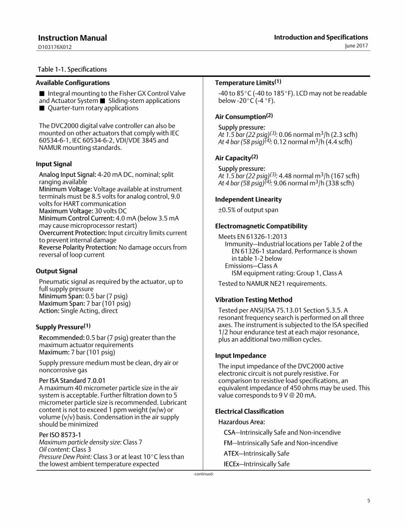
Table 1‐1. Specifications
Available Configurations
� Integral mounting to the Fisher GX Control Valveand Actuator System � Sliding-stem applications� Quarter-turn rotary applications
The DVC2000 digital valve controller can also bemounted on other actuators that comply with IEC60534-6-1, IEC 60534-6-2, VDI/VDE 3845 andNAMUR mounting standards.
Input Signal
Analog Input Signal: 4-20 mA DC, nominal; splitranging availableMinimum Voltage: Voltage available at instrumentterminals must be 8.5 volts for analog control, 9.0volts for HART communicationMaximum Voltage: 30 volts DCMinimum Control Current: 4.0 mA (below 3.5 mAmay cause microprocessor restart)Overcurrent Protection: Input circuitry limits currentto prevent internal damageReverse Polarity Protection: No damage occurs fromreversal of loop current
Output Signal
Pneumatic signal as required by the actuator, up tofull supply pressureMinimum Span: 0.5 bar (7 psig)Maximum Span: 7 bar (101 psig)Action: Single Acting, direct
Supply Pressure(1)
Recommended: 0.5 bar (7 psig) greater than themaximum actuator requirementsMaximum: 7 bar (101 psig)
Supply pressure medium must be clean, dry air ornoncorrosive gas
Per ISA Standard 7.0.01A maximum 40 micrometer particle size in the airsystem is acceptable. Further filtration down to 5micrometer particle size is recommended. Lubricantcontent is not to exceed 1 ppm weight (w/w) orvolume (v/v) basis. Condensation in the air supplyshould be minimized
Per ISO 8573-1Maximum particle density size: Class 7Oil content: Class 3Pressure Dew Point: Class 3 or at least 10�C less thanthe lowest ambient temperature expected
Temperature Limits(1)
-40 to 85�C (-40 to 185�F). LCD may not be readablebelow -20�C (-4 �F).
Air Consumption(2)
Supply pressure:At 1.5 bar (22 psig)(3): 0.06 normal m3/h (2.3 scfh)At 4 bar (58 psig)(4): 0.12 normal m3/h (4.4 scfh)
Air Capacity(2)
Supply pressure:At 1.5 bar (22 psig)(3): 4.48 normal m3/h (167 scfh)At 4 bar (58 psig)(4): 9.06 normal m3/h (338 scfh)
Independent Linearity
±0.5% of output span
Electromagnetic Compatibility
Meets EN 61326-1:2013�Immunity—Industrial locations per Table 2 of the��EN 61326-1 standard. Performance is shown��in table 1‐2 below�Emissions—Class A��ISM equipment rating: Group 1, Class A
Tested to NAMUR NE21 requirements.
Vibration Testing Method
Tested per ANSI/ISA 75.13.01 Section 5.3.5. Aresonant frequency search is performed on all threeaxes. The instrument is subjected to the ISA specified1/2 hour endurance test at each major resonance,plus an additional two million cycles.
Input Impedance
The input impedance of the DVC2000 activeelectronic circuit is not purely resistive. Forcomparison to resistive load specifications, anequivalent impedance of 450 ohms may be used. Thisvalue corresponds to 9 V @ 20 mA.
Electrical Classification
Hazardous Area:
CSA—Intrinsically Safe and Non-incendive
FM—Intrinsically Safe and Non-incendive
ATEX—Intrinsically Safe
IECEx—Intrinsically Safe
-continued-
Instruction ManualD103176X012
Introduction and SpecificationsJune 2017
6
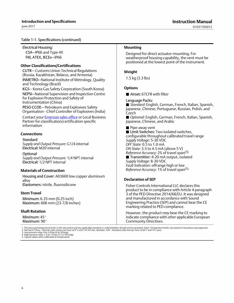
Table 1‐1. Specifications (continued)
Electrical Housing:
CSA—IP66 and Type 4X
FM, ATEX, IECEx—IP66
Other Classifications/Certifications
CUTR— Customs Union Technical Regulations(Russia, Kazakhstan, Belarus, and Armenia)
INMETRO—National Institute of Metrology, Qualityand Technology (Brazil)
KGS— Korea Gas Safety Corporation (South Korea)
NEPSI—National Supervision and Inspection Centrefor Explosion Protection and Safety ofInstrumentation (China)
PESO CCOE— Petroleum and Explosives SafetyOrganisation - Chief Controller of Explosives (India)
Contact your Emerson sales office or Local BusinessPartner for classification/certification specificinformation
Connections
StandardSupply and Output Pressure: G1/4 internalElectrical: M20 internal
OptionalSupply and Output Pressure: 1/4 NPT internalElectrical: 1/2 NPT internal
Materials of Construction
Housing and Cover: A03600 low copper aluminumalloyElastomers: nitrile, fluorosilicone
Stem Travel
Minimum: 6.35 mm (0.25 inch)Maximum: 606 mm (23-7/8 inches)
Shaft Rotation
Minimum: 45�Maximum: 90�
Mounting
Designed for direct actuator mounting. Forweatherproof housing capability, the vent must bepositioned at the lowest point of the instrument.
Weight
1.5 kg (3.3 lbs)
Options
� Airset: 67CFR with filter
Language Packs:� Standard: English, German, French, Italian, Spanish,Japanese, Chinese, Portuguese, Russian, Polish, andCzech� Optional: English, German, French, Italian, Spanish,Japanese, Chinese, and Arabic
� Pipe-away vent� Limit Switches: Two isolated switches,configurable throughout calibrated travel rangeSupply Voltage: 5-30 VDCOFF State: 0.5 to 1.0 mAON State: 3.5 to 4.5 mA (above 5 V)Reference Accuracy: 2% of travel span(5)
� Transmitter: 4-20 mA output, isolated Supply Voltage: 8-30 VDCFault Indication: offrange high or lowReference Accuracy: 1% of travel span(5)
Declaration of SEP
Fisher Controls International LLC declares thisproduct to be in compliance with Article 4 paragraph3 of the PED Directive 2014/68/EU. It was designedand manufactured in accordance with SoundEngineering Practice (SEP) and cannot bear the CEmarking related to PED compliance.
However, the product may bear the CE marking toindicate compliance with other applicable EuropeanCommunity Directives.
1. The pressure/temperature limits in this document and any applicable standard or code limitation should not be exceeded. Note: Temperature limits vary based on hazardous area approval.2. Normal m3/hour - Normal cubic meters per hour at 0�C and 1.01325 bar, absolute. Scfh - Standard cubic feet per hour at 60�F and 14.7 psia.3. Low pressure relay: 0 to 3.4 bar (0 to 50 psig).4. High pressure relay: 3.5 to 7.0 bar (51 to 102 psig).5. Typical values when calibrated at temperature.
Instruction ManualD103176X012
Introduction and SpecificationsJune 2017
7
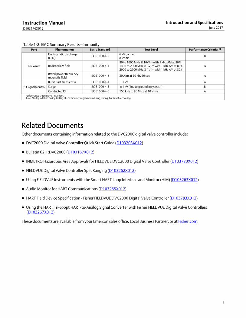
Table 1‐2. EMC Summary Results—ImmunityPort Phenomenon Basic Standard Test Level Performance Criteria(1)
Enclosure
Electrostatic discharge(ESD)
IEC 61000-4-26 kV contact8 kV air
B
Radiated EM field IEC 61000-4-380 to 1000 MHz @ 10V/m with 1 kHz AM at 80%1400 to 2000 MHz @ 3V/m with 1 kHz AM at 80%2000 to 2700 MHz @ 1V/m with 1 kHz AM at 80%
A
Rated power frequencymagnetic field
IEC 61000-4-8 30 A/m at 50 Hz, 60 sec A
I/O signal/control
Burst (fast transients) IEC 61000-4-4 �1 kV A
Surge IEC 61000-4-5 �1 kV (line to ground only, each) B
Conducted RF IEC 61000-4-6 150 kHz to 80 MHz at 10 Vrms A
Performance criteria is + / - 1% effect.1. A = No degradation during testing. B = Temporary degradation during testing, but is self-recovering.
Related DocumentsOther documents containing information related to the DVC2000 digital valve controller include:
� DVC2000 Digital Valve Controller Quick Start Guide (D103203X012)
� Bulletin 62.1:DVC2000 (D103167X012)
� INMETRO Hazardous Area Approvals for FIELDVUE DVC2000 Digital Valve Controller (D103780X012)
� FIELDVUE Digital Valve Controller Split Ranging (D103262X012)
� Using FIELDVUE Instruments with the Smart HART Loop Interface and Monitor (HIM) (D103263X012)
� Audio Monitor for HART Communications (D103265X012)
� HART Field Device Specification - Fisher FIELDVUE DVC2000 Digital Valve Controller (D103783X012)
� Using the HART Tri-Loopt HART-to-Analog Signal Converter with Fisher FIELDVUE Digital Valve Controllers(D103267X012)
These documents are available from your Emerson sales office, Local Business Partner, or at Fisher.com.
Instruction ManualD103176X012
Introduction and SpecificationsJune 2017
8
Educational ServicesFor information on available courses for the DVC2000 digital valve controller, as well as a variety of other products,contact:
Emerson Automation SolutionsEducational Services - RegistrationPhone: 1-641-754-3771 or 1-800-338-8158E-mail: [email protected]/fishervalvetraining
Instruction ManualD103176X012
Detailed Setup and CalibrationJune 2017
9
Section 2 Detailed Configuration and Calibration via HARTCommunication2‐2‐
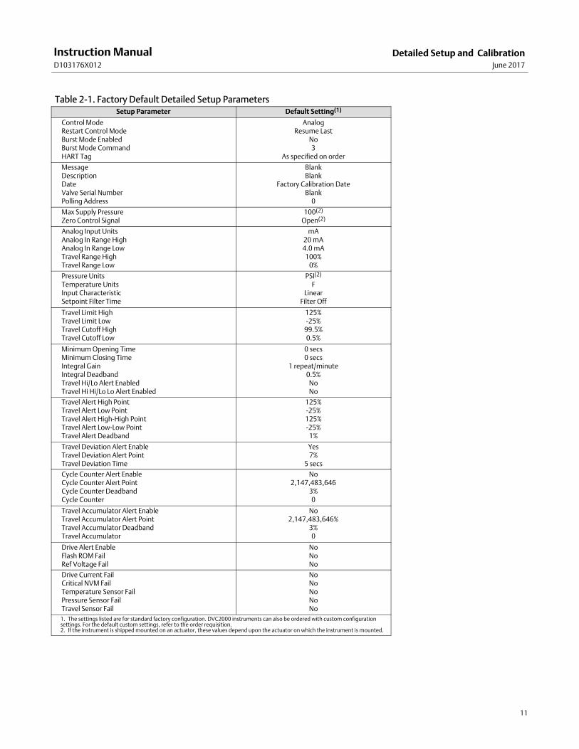
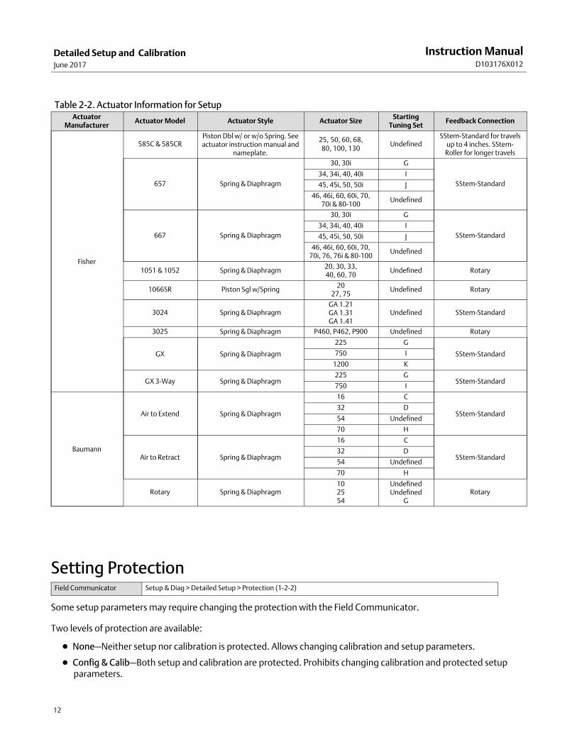
Detailed SetupThe DVC2000 digital valve controller has the capability to communicate via the HART protocol. This section describesthe advanced features that can be accessed with the Field Communicator. Table 2‐1 lists the default settings for astandard factory configuration. Table 2‐2 provides the actuator information required to setup and calibrate theinstrument.
Setting ModesField Communicator Setup & Diag > Detailed Setup > Mode (1-2-1)
Instrument Mode
You can change the instrument mode by selecting Instrument Mode from the Mode menu, or press the Hot Key andselect Instrument Mode.
Instrument Mode allows you to either take the instrument Out Of Service or place it In Service. Taking the instrumentOut Of Service allows you to perform instrument calibration and also allows you to change setup variables that affectcontrol, provided the calibration/configuration protection is properly set. See Setting Protection.
Note
Some changes that require the instrument to be taken Out Of Service will not take effect until the instrument is placed back InService or the instrument is restarted.
Control Mode
You can change the control mode by selecting Control Mode from the Mode menu, or press the Hot Key and selectControl Mode.
Control Mode lets you define where the instrument receives its set point. Follow the prompts on the FieldCommunicator display to choose one of the following control modes: Analog or Digital.
Choose Analog if the instrument is to receive its set point over the 4-20 mA loop. Normally the instrument controlmode is Analog.
Choose Digital if the instrument is to receive its set point digitally, via the HART communications link.
A third mode, Test, is also displayed. Normally the instrument should not be in the Test mode. The FieldCommunicator automatically switches to this mode whenever it needs to stroke the valve, for example during
Instruction ManualD103176X012
Detailed Setup and CalibrationJune 2017
10
calibration or stroke valve. However, if you abort from a procedure where the instrument is in the Test mode, it mayremain in this mode. To take the instrument out of the Test mode, select Control Mode then select either Analog orDigital.
Restart Control Mode
Restart Control Mode (Restart Cont Mode) lets you choose which operating mode you want the instrument to be inafter a restart. Follow the prompts on the Field Communicator display to define the restart control mode as ResumeLast, Analog, or Digital.
Restarting the Instrument
Restart resets the instrument in the same manner as when power to the instrument is interrupted. When Restart isissued, all of the newly entered configuration variables become active. Otherwise, they may not take effect until theinstrument is placed In Service.
Burst Mode
Enabling burst mode provides continuous communication from the digital valve controller. Burst mode applies only tothe transmission of burst mode data (analog input, travel target, pressure, and travel) and does not affect the wayother data is accessed.
Access to information in the instrument is normally obtained through the poll/response of HART communication. TheField Communicator or the control system may request any of the information that is normally available, even whilethe instrument is in burst mode. Between each burst mode transmission sent by the instrument, a short pause allowsthe Field Communicator or control system to initiate a request. The instrument receives the request, processes theresponse message, and then continues “bursting” the burst mode data.
There are four burst mode commands. Command 3 is recommended for use with the Rosemount� 333 HARTTri-Loop� HART-to-analog signal converter. The other three are not used at this time.
Command 3 provides the following variables:
� Primary variable—analog input in % or mA,
� Secondary variable—travel target (valve set point) in % of ranged travel,
� Tertiary variable—output pressure in psig, bar, or kPa,
� Quaternary variable—travel in % of ranged travel.
To enable burst mode select Mode > Burst > Burst Enable. To send a burst mode command, select Burst Command. Burst mode must be enabled before you can change the burst mode command.
Instruction ManualD103176X012
Detailed Setup and CalibrationJune 2017
11
Table 2‐1. Factory Default Detailed Setup ParametersSetup Parameter Default Setting(1)
Control ModeRestart Control ModeBurst Mode EnabledBurst Mode CommandHART Tag
AnalogResume Last
No3
As specified on order
MessageDescriptionDateValve Serial NumberPolling Address
BlankBlank
Factory Calibration DateBlank
0
Max Supply PressureZero Control Signal
100(2)
Open(2)
Analog Input UnitsAnalog In Range HighAnalog In Range LowTravel Range HighTravel Range Low
mA20 mA4.0 mA100%
0%
Pressure UnitsTemperature UnitsInput CharacteristicSetpoint Filter Time
PSI(2)
FLinear
Filter Off
Travel Limit HighTravel Limit LowTravel Cutoff HighTravel Cutoff Low
125%-25%
99.5%0.5%
Minimum Opening TimeMinimum Closing TimeIntegral GainIntegral DeadbandTravel Hi/Lo Alert EnabledTravel Hi Hi/Lo Lo Alert Enabled
0 secs0 secs
1 repeat/minute0.5%
NoNo
Travel Alert High PointTravel Alert Low PointTravel Alert High-High PointTravel Alert Low-Low PointTravel Alert Deadband
125%-25%125%-25%
1%
Travel Deviation Alert EnableTravel Deviation Alert PointTravel Deviation Time
Yes7%
5 secs
Cycle Counter Alert EnableCycle Counter Alert PointCycle Counter DeadbandCycle Counter
No2,147,483,646
3%0
Travel Accumulator Alert EnableTravel Accumulator Alert PointTravel Accumulator DeadbandTravel Accumulator
No2,147,483,646%
3%0
Drive Alert EnableFlash ROM FailRef Voltage Fail
NoNoNo
Drive Current FailCritical NVM FailTemperature Sensor FailPressure Sensor FailTravel Sensor Fail
NoNoNoNoNo
1. The settings listed are for standard factory configuration. DVC2000 instruments can also be ordered with custom configurationsettings. For the default custom settings, refer to the order requisition.2. If the instrument is shipped mounted on an actuator, these values depend upon the actuator on which the instrument is mounted.
Instruction ManualD103176X012
Detailed Setup and CalibrationJune 2017
12
Table 2‐2. Actuator Information for SetupActuator
ManufacturerActuator Model Actuator Style Actuator Size
StartingTuning Set
Feedback Connection
Fisher
585C & 585CRPiston Dbl w/ or w/o Spring. Seeactuator instruction manual and
nameplate.
25, 50, 60, 68,80, 100, 130
UndefinedSStem-Standard for travels
up to 4 inches. SStem-Roller for longer travels
657 Spring & Diaphragm
30, 30i G
SStem-Standard
34, 34i, 40, 40i I
45, 45i, 50, 50i J
46, 46i, 60, 60i, 70,70i & 80-100
Undefined
667 Spring & Diaphragm
30, 30i G
SStem-Standard
34, 34i, 40, 40i I
45, 45i, 50, 50i J
46, 46i, 60, 60i, 70,70i, 76, 76i & 80-100
Undefined
1051 & 1052 Spring & Diaphragm20, 30, 33,40, 60, 70
Undefined Rotary
1066SR Piston Sgl w/Spring20
27, 75Undefined Rotary
3024 Spring & DiaphragmGA 1.21GA 1.31GA 1.41
Undefined SStem-Standard
3025 Spring & Diaphragm P460, P462, P900 Undefined Rotary
GX Spring & Diaphragm
225 G
SStem-Standard750 I
1200 K
GX 3-Way Spring & Diaphragm225 G
SStem-Standard750 I
Baumann
Air to Extend Spring & Diaphragm
16 C
SStem-Standard32 D
54 Undefined
70 H
Air to Retract Spring & Diaphragm
16 C
SStem-Standard32 D
54 Undefined
70 H
Rotary Spring & Diaphragm102554
UndefinedUndefined
GRotary
Setting Protection Field Communicator Setup & Diag > Detailed Setup > Protection (1-2-2)
Some setup parameters may require changing the protection with the Field Communicator.
Two levels of protection are available:
� None—Neither setup nor calibration is protected. Allows changing calibration and setup parameters.
� Config & Calib—Both setup and calibration are protected. Prohibits changing calibration and protected setupparameters.
Instruction ManualD103176X012
Detailed Setup and CalibrationJune 2017
13
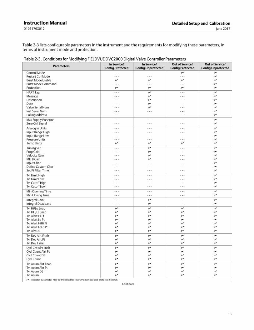
Table 2‐3 lists configurable parameters in the instrument and the requirements for modifying these parameters, interms of instrument mode and protection.
Table 2‐3. Conditions for Modifying FIELDVUE DVC2000 Digital Valve Controller Parameters
ParametersIn Service/
Config ProtectedIn Service/
Config UnprotectedOut of Service/
Config ProtectedOut of Service/
Config Unprotected
Control ModeRestart Ctrl ModeBurst Mode EnableBurst Mode CommandProtection
- - -- - -�- - -�
- - -- - -�- - -�
�- - -�- - -�
�����
HART TagMessageDescriptionDateValve Serial NumInst Serial NumPolling Address
- - -- - -- - -- - -- - -- - -- - -
�����- - -- - -
- - -- - -- - -- - -- - -- - -- - -
�������
Max Supply PressureZero Ctrl Signal
- - -- - -
- - -- - -
- - -- - -
��
Analog In UnitsInput Range HighInput Range LowPressure UnitsTemp Units
- - -- - -- - -- - -�
- - -- - -- - -- - -�
- - -- - -- - -- - -�
�����
Tuning SetProp GainVelocity GainMLFB GainInput CharDefine Custom CharSet Pt Filter Time
- - -- - -- - -- - -- - -- - -- - -
����- - -- - -- - -
- - -- - -- - -- - -- - -- - -- - -
�������
Tvl Limit HighTvl Limit LowTvl Cutoff HighTvl Cutoff Low
- - -- - -- - -- - -
- - -- - -- - -- - -
- - -- - -- - -- - -
����
Min Opening TimeMin Closing Time
- - -- - -
- - -- - -
- - -- - -
��
Integral GainIntegral Deadband
- - -- - -
��
- - -- - -
��
Tvl Hi/Lo EnabTvl HH/LL EnabTvl Alert Hi PtTvl Alert Lo PtTvl Alert HiHi PtTvl Alert LoLo PtTvl Alrt DB
�������
�������
�������
�������
Tvl Dev Alrt EnabTvl Dev Alrt PtTvl Dev Time
���
���
���
���
Cycl Cnt Alrt EnabCycl Count Alrt PtCycl Count DBCycl Count
����
����
����
����
Tvl Acum Alrt EnabTvl Acum Alrt PtTvl Acum DBTvl Acum
����
����
����
����
�—indicates parameter may be modified for instrument mode and protection shown.
-Continued-
Instruction ManualD103176X012
Detailed Setup and CalibrationJune 2017
14
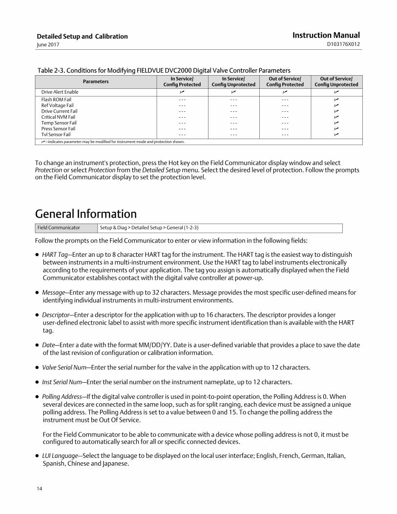
Table 2‐3. Conditions for Modifying FIELDVUE DVC2000 Digital Valve Controller Parameters
ParametersIn Service/
Config ProtectedIn Service/
Config UnprotectedOut of Service/
Config ProtectedOut of Service/
Config Unprotected
Drive Alert Enable � � � �
Flash ROM FailRef Voltage FailDrive Current FailCritical NVM FailTemp Sensor FailPress Sensor FailTvl Sensor Fail
- - -- - -- - -- - -- - -- - -- - -
- - -- - -- - -- - -- - -- - -- - -
- - -- - -- - -- - -- - -- - -- - -
�������
�—indicates parameter may be modified for instrument mode and protection shown.
To change an instrument's protection, press the Hot key on the Field Communicator display window and selectProtection or select Protection from the Detailed Setup menu. Select the desired level of protection. Follow the promptson the Field Communicator display to set the protection level.
General InformationField Communicator Setup & Diag > Detailed Setup > General (1-2-3)
Follow the prompts on the Field Communicator to enter or view information in the following fields:
� HART Tag—Enter an up to 8 character HART tag for the instrument. The HART tag is the easiest way to distinguishbetween instruments in a multi-instrument environment. Use the HART tag to label instruments electronicallyaccording to the requirements of your application. The tag you assign is automatically displayed when the FieldCommunicator establishes contact with the digital valve controller at power-up.
� Message—Enter any message with up to 32 characters. Message provides the most specific user-defined means foridentifying individual instruments in multi-instrument environments.
� Descriptor—Enter a descriptor for the application with up to 16 characters. The descriptor provides a longeruser-defined electronic label to assist with more specific instrument identification than is available with the HARTtag.
� Date—Enter a date with the format MM/DD/YY. Date is a user-defined variable that provides a place to save the dateof the last revision of configuration or calibration information.
� Valve Serial Num—Enter the serial number for the valve in the application with up to 12 characters.
� Inst Serial Num—Enter the serial number on the instrument nameplate, up to 12 characters.
� Polling Address—If the digital valve controller is used in point-to-point operation, the Polling Address is 0. Whenseveral devices are connected in the same loop, such as for split ranging, each device must be assigned a uniquepolling address. The Polling Address is set to a value between 0 and 15. To change the polling address theinstrument must be Out Of Service.
For the Field Communicator to be able to communicate with a device whose polling address is not 0, it must beconfigured to automatically search for all or specific connected devices.
� LUI Language—Select the language to be displayed on the local user interface; English, French, German, Italian,Spanish, Chinese and Japanese.
Instruction ManualD103176X012
Detailed Setup and CalibrationJune 2017
15
Measured Variable Units and RangesField Communicator Setup & Diag > Detailed Setup > Measured Var (1-2-4)
Follow the prompts on the Field Communicator to define the following measured variables units and ranges:
� Analog In Units—Permits defining the Analog Input Units in mA or percent of 4-20 mA range.
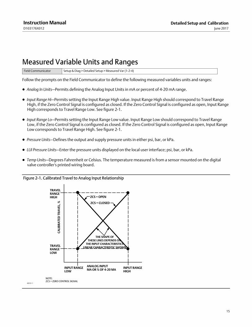
� Input Range Hi—Permits setting the Input Range High value. Input Range High should correspond to Travel RangeHigh, if the Zero Control Signal is configured as closed. If the Zero Control Signal is configured as open, Input RangeHigh corresponds to Travel Range Low. See figure 2‐1.
� Input Range Lo—Permits setting the Input Range Low value. Input Range Low should correspond to Travel RangeLow, if the Zero Control Signal is configured as closed. If the Zero Control Signal is configured as open, Input RangeLow corresponds to Travel Range High. See figure 2‐1.
� Pressure Units—Defines the output and supply pressure units in either psi, bar, or kPa.
� LUI Pressure Units—Enter the pressure units displayed on the local user interface; psi, bar, or kPa.
� Temp Units—Degrees Fahrenheit or Celsius. The temperature measured is from a sensor mounted on the digitalvalve controller's printed wiring board.
Figure 2‐1. Calibrated Travel to Analog Input Relationship
TRAVELRANGEHIGH
TRAVELRANGELOW
THE SHAPE OFTHESE LINES DEPENDS ON
THE INPUT CHARACTERISTICSLINEAR CHARACTERISTIC SHOWN
INPUT RANGELOW
INPUT RANGEHIGH
ANALOG INPUTMA OR % OF 4-20 MA
CA
LIB
RA
TE
D T
RA
VE
L, %
A6531-1
ZCS = CLOSED
ZCS = OPEN
NOTE:ZCS = ZERO CONTROL SIGNAL
Instruction ManualD103176X012
Detailed Setup and CalibrationJune 2017
16
Actuator and Valve InformationField Communicator Setup & Diag > Detailed Setup > Actuator & Valve (1-2-5)
Follow the prompts on the Field Communicator to edit or view information in the following fields:
� Max Supply Press—Enter the maximum supply pressure in psi, bar, or kPa, depending on what was selected forpressure units.
Note
If the actual measured pressure exceeds this setting by 25%, the pressure measurement will not be displayed.
� Actuator Style—Enter the actuator style, spring and diaphragm, piston double-acting without spring, pistonsingle-acting with spring, or piston double-acting with spring.
� Valve Style—Enter the valve style, rotary or sliding-stem
� Zero Control Signal—Identifies whether the valve is fully open or fully closed when the input is 0%. If you are unsurehow to set this parameter, disconnect the current source to the instrument. The resulting valve travel is the ZeroControl Signal. (With direct acting digital valve controllers, disconnecting the current source is the same as settingthe output pressure to zero.)
Setting ResponseField Communicator Setup & Diag > Detailed Setup > Response Control (1-2-6)
Follow the prompts on the Field Communicator to configure the following response control parameters:
WARNING
Changes to the tuning set may cause the valve/actuator assembly to stroke. To avoid personal injury and property damagecaused by moving parts, keep hands, tools, and other objects away from the valve/actuator assembly.
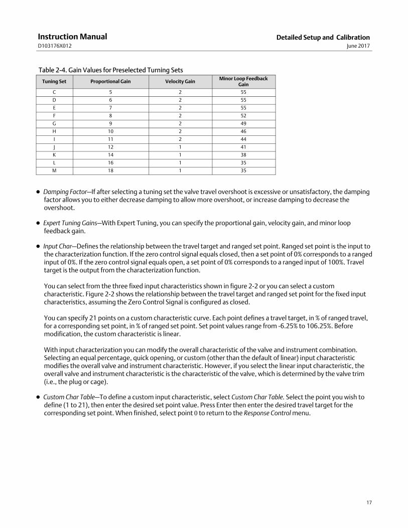
� Tuning Set—There are eleven tuning sets to choose from. Each tuning set provides a preselected value for the digitalvalve controller gain settings. Tuning set C provides the slowest response and M provides the fastest response.Table 2‐4 lists the proportional gain, velocity gain, and minor loop feedback gain values for preselected tuning sets.
Instruction ManualD103176X012
Detailed Setup and CalibrationJune 2017
17
Table 2‐4. Gain Values for Preselected Turning Sets
Tuning Set Proportional Gain Velocity GainMinor Loop Feedback
Gain
C 5 2 55
D 6 2 55
E 7 2 55
F 8 2 52
G 9 2 49
H 10 2 46
I 11 2 44
J 12 1 41
K 14 1 38
L 16 1 35
M 18 1 35
� Damping Factor—If after selecting a tuning set the valve travel overshoot is excessive or unsatisfactory, the dampingfactor allows you to either decrease damping to allow more overshoot, or increase damping to decrease theovershoot.
� Expert Tuning Gains—With Expert Tuning, you can specify the proportional gain, velocity gain, and minor loopfeedback gain.
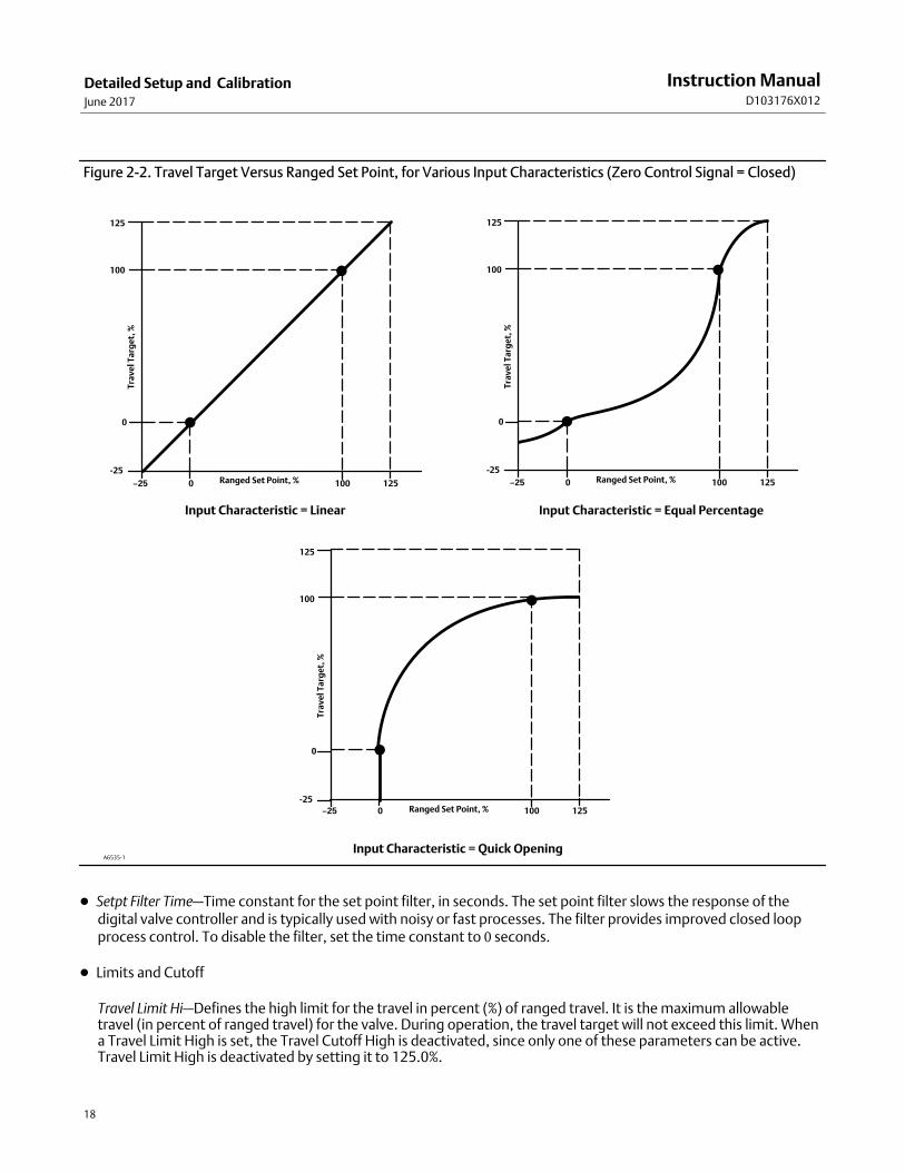
� Input Char—Defines the relationship between the travel target and ranged set point. Ranged set point is the input tothe characterization function. If the zero control signal equals closed, then a set point of 0% corresponds to a rangedinput of 0%. If the zero control signal equals open, a set point of 0% corresponds to a ranged input of 100%. Traveltarget is the output from the characterization function.
You can select from the three fixed input characteristics shown in figure 2‐2 or you can select a customcharacteristic. Figure 2‐2 shows the relationship between the travel target and ranged set point for the fixed inputcharacteristics, assuming the Zero Control Signal is configured as closed.
You can specify 21 points on a custom characteristic curve. Each point defines a travel target, in % of ranged travel,for a corresponding set point, in % of ranged set point. Set point values range from -6.25% to 106.25%. Beforemodification, the custom characteristic is linear.
With input characterization you can modify the overall characteristic of the valve and instrument combination.Selecting an equal percentage, quick opening, or custom (other than the default of linear) input characteristicmodifies the overall valve and instrument characteristic. However, if you select the linear input characteristic, theoverall valve and instrument characteristic is the characteristic of the valve, which is determined by the valve trim(i.e., the plug or cage).
� Custom Char Table—To define a custom input characteristic, select Custom Char Table. Select the point you wish todefine (1 to 21), then enter the desired set point value. Press Enter then enter the desired travel target for thecorresponding set point. When finished, select point 0 to return to the Response Control menu.
Instruction ManualD103176X012
Detailed Setup and CalibrationJune 2017
18
Figure 2‐2. Travel Target Versus Ranged Set Point, for Various Input Characteristics (Zero Control Signal = Closed)
Tra
ve
l Ta
rge
t, %
Ranged Set Point, %−25 0 125100 −25 0 125100
−25 0 125100
Input Characteristic = Linear Input Characteristic = Equal Percentage
Input Characteristic = Quick Opening
100
0
-25
125
Tra
ve
l Ta
rge
t, %
100
0
-25
125
Ranged Set Point, %
Tra
ve
l Ta
rge
t, %
100
0
-25
125
Ranged Set Point, %
A6535-1
� Setpt Filter Time—Time constant for the set point filter, in seconds. The set point filter slows the response of thedigital valve controller and is typically used with noisy or fast processes. The filter provides improved closed loopprocess control. To disable the filter, set the time constant to 0 seconds.
� Limits and Cutoff
Travel Limit Hi—Defines the high limit for the travel in percent (%) of ranged travel. It is the maximum allowabletravel (in percent of ranged travel) for the valve. During operation, the travel target will not exceed this limit. Whena Travel Limit High is set, the Travel Cutoff High is deactivated, since only one of these parameters can be active.Travel Limit High is deactivated by setting it to 125.0%.

Instruction ManualD103176X012
Detailed Setup and CalibrationJune 2017
19
Travel Limit Lo—Defines the low limit for the travel in percent (%) of ranged travel. It is the minimum allowable travel(in percent of ranged travel) for the valve. During operation, the travel target will not exceed this limit. When aTravel Limit Low is set, the Travel Cutoff Low is deactivated, since only one of these parameters can be active. TravelLimit Low is deactivated by setting it to -25.0%.
Travel Cutoff Hi—Defines the high cutoff point for the travel in percent (%) of ranged travel. Above this cutoff, thetravel target is set to 123.0% of the ranged travel. When a Travel Cutoff High is set, the Travel Limit High isdeactivated, since only one of these parameters can be active. Travel Cutoff High is deactivated by setting it to125.0%.
Travel Cutoff Lo—Defines the low cutoff point for the travel. Travel Cutoff Low can be used to ensure proper seat loadis applied to the valve. When below the travel cutoff low, the output is set to zero or to full supply pressure,depending upon the zero control signal. A Travel Cutoff Low of 0.5% is recommended to help ensure maximumshutoff seat loading.
When a Travel Cutoff Low is set, the Travel Limit Low is deactivated, since only one of these parameters can beactive. Travel Cutoff Low is deactivated by setting it to -25.0%.
� Min Open/Close
Min Opening Time—Minimum Opening Time is configured in seconds and defines the minimum time for the travel toincrease the entire ranged travel. This rate is applied to any travel increases. A value of 0.0 seconds deactivates thisfeature and allows the valve to stroke open as fast as possible. This parameter should be set to 0 in firmware 1, 2, 3,and 4.
Min Closing Time—Minimum Closing Time is configured in seconds and defines the minimum time for the travel todecrease the entire ranged travel. This rate is applied to any travel decreases. A value of 0.0 seconds deactivates thisfeature and allows the valve to stroke closed as fast as possible. This parameter should be set to 0 in firmware 1, 2,3, and 4.
� Integral Settings
Enab Int Control—Select Yes or No
Integral Gain—By setting this value to 0.0 the positioner integrator is disabled. Any other value will provide resetaction to improve static performance.
Integral Dead Zone—When the travel target and actual target deviate by less than this amount, the integrator isautomatically disabled. This prevents the positioner integrator from fighting with the process controller integratorwhich may result in valve oscillation.
Setting AlertsField Communicator Setup & Diag > Detailed Setup > Alerts (1-2-7)
The following menus are available for configuring Alerts. Items on the menus may be changed with the instrument InService. Protection does not need to be removed (no need to set to None). Alerts are not processed when a Diagnosticis in progress. Follow the prompts on the Field Communicator display to configure alerts.
Note
Alerts are not available with instrument level AC.
Instruction ManualD103176X012
Detailed Setup and CalibrationJune 2017
20
Setting Travel Alerts
Setting High, High-High, Low and Low-Low Alerts
Follow the prompts on the Field Communicator to set the following travel alerts:
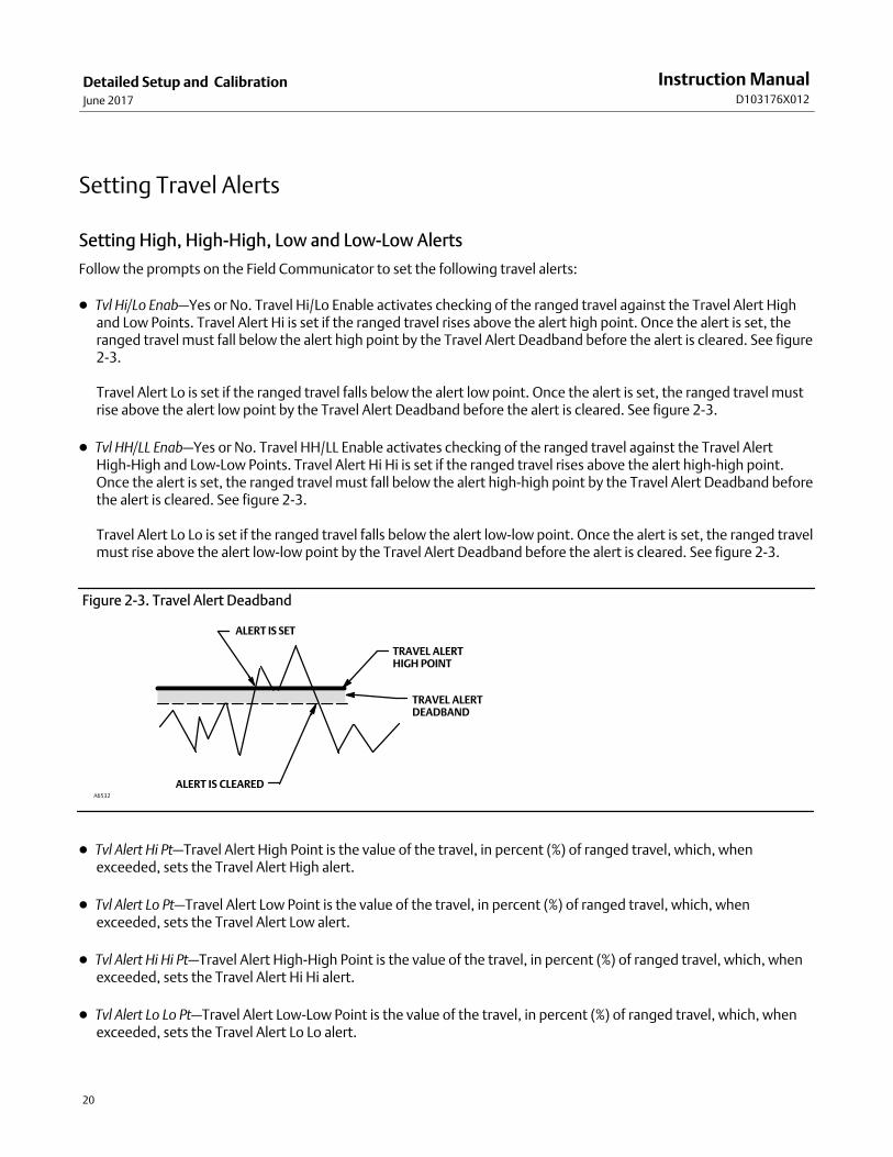
� Tvl Hi/Lo Enab—Yes or No. Travel Hi/Lo Enable activates checking of the ranged travel against the Travel Alert Highand Low Points. Travel Alert Hi is set if the ranged travel rises above the alert high point. Once the alert is set, theranged travel must fall below the alert high point by the Travel Alert Deadband before the alert is cleared. See figure2‐3.
Travel Alert Lo is set if the ranged travel falls below the alert low point. Once the alert is set, the ranged travel mustrise above the alert low point by the Travel Alert Deadband before the alert is cleared. See figure 2‐3.
� Tvl HH/LL Enab—Yes or No. Travel HH/LL Enable activates checking of the ranged travel against the Travel AlertHigh-High and Low-Low Points. Travel Alert Hi Hi is set if the ranged travel rises above the alert high-high point.Once the alert is set, the ranged travel must fall below the alert high-high point by the Travel Alert Deadband beforethe alert is cleared. See figure 2‐3.
Travel Alert Lo Lo is set if the ranged travel falls below the alert low-low point. Once the alert is set, the ranged travelmust rise above the alert low-low point by the Travel Alert Deadband before the alert is cleared. See figure 2‐3.
Figure 2‐3. Travel Alert Deadband
ALERT IS CLEARED
ALERT IS SET
TRAVEL ALERTHIGH POINT
TRAVEL ALERTDEADBAND
A6532
� Tvl Alert Hi Pt—Travel Alert High Point is the value of the travel, in percent (%) of ranged travel, which, whenexceeded, sets the Travel Alert High alert.
� Tvl Alert Lo Pt—Travel Alert Low Point is the value of the travel, in percent (%) of ranged travel, which, whenexceeded, sets the Travel Alert Low alert.
� Tvl Alert Hi Hi Pt—Travel Alert High-High Point is the value of the travel, in percent (%) of ranged travel, which, whenexceeded, sets the Travel Alert Hi Hi alert.
� Tvl Alert Lo Lo Pt—Travel Alert Low-Low Point is the value of the travel, in percent (%) of ranged travel, which, whenexceeded, sets the Travel Alert Lo Lo alert.
Instruction ManualD103176X012
Detailed Setup and CalibrationJune 2017
21
� Tvl Alrt DB—Travel Alert Deadband is the travel, in percent (%) of ranged travel, required to clear a travel alert, once ithas been set. The deadband applies to both Travel Alert Hi/Lo and Travel Alert Hi Hi/Lo Lo. See figure 2‐3.
Note
The Travel Alert Deadband applies to the Travel Deviation as well as Travel Alert Hi/Lo and Travel Alert Hi Hi/Lo Lo.
Setting Travel Deviation Alert
Follow the prompts on the Field Communicator to set the following travel deviation alerts:
� Tvl Dev Alrt Enab—Yes or No. When enabled, checks the difference between the travel target and the actual travel. Ifthe difference exceeds the Travel Deviation Alert Point for more than the Travel Deviation Time, the TravelDeviation Alert is set. It remains set until the difference between the travel target and the actual travel is less thanthe Travel Deviation Alert Point minus the Travel Alert Deadband.
� Tvl Dev Alrt Pt—Travel Deviation Alert Point is the alert point for the difference, expressed in percent (%), betweenthe travel target and the actual travel. When the difference exceeds the alert point for more than the TravelDeviation Time, the Travel Deviation Alert is set.
� Tvl Dev Time—Travel Deviation Time is the time, in seconds, that the travel deviation must exceed the TravelDeviation Alert Point before the alert is set.
Setting Travel Accumulation Alert
Follow the prompts on the Field Communicator to set the following travel accumulation alerts:
� Tvl Acum Alrt Enab—Yes or No. Travel Accumulator Alert Enable activates checking of the difference between theTravel Accumulator value and the Travel Accumulator Alert Point. The Travel Accumulator Alert is set when theTravel Accumulator value exceeds the Travel Accumulator Alert Point. It is cleared after you reset the TravelAccumulator to a value less than the alert point.
� Tvl Accum Alrt Pt—Travel Accumulator Alert Point is the value of the Travel Accumulator, in percent (%) of rangedtravel, which, when exceeded, sets the Travel Accumulator Alert.
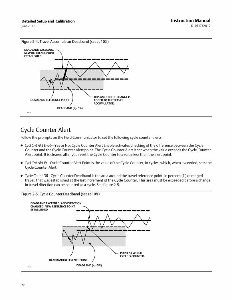
� Tvl Accum DB—Travel Accumulator Deadband is the area around the travel reference point, in percent (%) of rangedtravel, that was established at the last increment of the accumulator. This area must be exceeded before a changein travel can be accumulated. See figure 2‐4.
� Tvl Accum—Travel Accumulator records the total change in travel, in percent (%) of ranged travel, since theaccumulator was last cleared. The value of the Travel Accumulator increments when the magnitude of the changeexceeds the Travel Accumulator Dead- band. See figure 2‐4. You can reset the Travel Accumulator by configuring itto zero.
Instruction ManualD103176X012
Detailed Setup and CalibrationJune 2017
22
A6534
Figure 2‐4. Travel Accumulator Deadband (set at 10%)
DEADBAND (+/- 5%)
DEADBAND EXCEEDED,NEW REFERENCE POINTESTABLISHED
THIS AMOUNT OF CHANGE ISADDED TO THE TRAVELACCUMULATOR.
DEADBAND REFERENCE POINT
Cycle Counter AlertFollow the prompts on the Field Communicator to set the following cycle counter alerts:
� Cycl Cnt Alrt Enab—Yes or No. Cycle Counter Alert Enable activates checking of the difference between the CycleCounter and the Cycle Counter Alert point. The Cycle Counter Alert is set when the value exceeds the Cycle CounterAlert point. It is cleared after you reset the Cycle Counter to a value less than the alert point.
� Cycl Cnt Alrt Pt—Cycle Counter Alert Point is the value of the Cycle Counter, in cycles, which, when exceeded, sets theCycle Counter Alert.
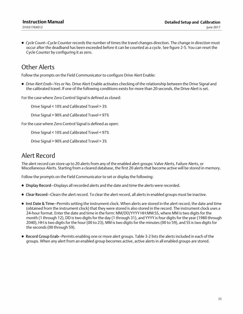
� Cycle Count DB—Cycle Counter Deadband is the area around the travel reference point, in percent (%) of rangedtravel, that was established at the last increment of the Cycle Counter. This area must be exceeded before a changein travel direction can be counted as a cycle. See figure 2‐5.
A6533-1
Figure 2‐5. Cycle Counter Deadband (set at 10%)
DEADBAND (+/- 5%)
DEADBAND EXCEEDED, AND DIRECTIONCHANGED, NEW REFERENCE POINTESTABLISHED
POINT AT WHICHCYCLE IS COUNTED.
DEADBAND REFERENCE POINT
Instruction ManualD103176X012
Detailed Setup and CalibrationJune 2017
23
� Cycle Count—Cycle Counter records the number of times the travel changes direction. The change in direction mustoccur after the deadband has been exceeded before it can be counted as a cycle. See figure 2‐5. You can reset theCycle Counter by configuring it as zero.
Other AlertsFollow the prompts on the Field Communicator to configure Drive Alert Enable:
� Drive Alert Enab—Yes or No. Drive Alert Enable activates checking of the relationship between the Drive Signal andthe calibrated travel. If one of the following conditions exists for more than 20 seconds, the Drive Alert is set.
For the case where Zero Control Signal is defined as closed:
Drive Signal < 10% and Calibrated Travel > 3%
Drive Signal > 90% and Calibrated Travel < 97%
For the case where Zero Control Signal is defined as open:
Drive Signal < 10% and Calibrated Travel < 97%
Drive Signal > 90% and Calibrated Travel > 3%
Alert RecordThe alert record can store up to 20 alerts from any of the enabled alert groups: Valve Alerts, Failure Alerts, orMiscellaneous Alerts. Starting from a cleared database, the first 20 alerts that become active will be stored in memory.
Follow the prompts on the Field Communicator to set or display the following:
� Display Record—Displays all recorded alerts and the date and time the alerts were recorded.
� Clear Record—Clears the alert record. To clear the alert record, all alerts in enabled groups must be inactive.
� Inst Date & Time—Permits setting the instrument clock. When alerts are stored in the alert record, the date and time(obtained from the instrument clock) that they were stored is also stored in the record. The instrument clock uses a24-hour format. Enter the date and time in the form: MM/DD/YYYY HH:MM:SS, where MM is two digits for themonth (1 through 12), DD is two digits for the day (1 through 31), and YYYY is four digits for the year (1980 through2040), HH is two digits for the hour (00 to 23), MM is two digits for the minutes (00 to 59), and SS is two digits forthe seconds (00 through 59).
� Record Group Enab—Permits enabling one or more alert groups. Table 3‐2 lists the alerts included in each of thegroups. When any alert from an enabled group becomes active, active alerts in all enabled groups are stored.
Instruction ManualD103176X012
Detailed Setup and CalibrationJune 2017
24
Self Test Failures for Instrument ShutdownField Communicator Setup & Diag > Detailed Setup > Self Test Shutdown (1-2-8)
Upon shutdown, the instrument attempts to drive its output pressure to the zero current condition and no longerexecutes its control function. In addition, the appropriate failure statuses are set. Once the problem that caused theshutdown has been fixed, the instrument can be restarted by cycling the power or selecting Restart from the Modemenu of the Field Communicator. Also see the Viewing Instrument Status section on page 35 for further details aboutfailures.
Follow the prompts on the Field Communicator display to determine the self test shutdown criteria from thefollowing:
� Done—Select this if you are done modifying the self test shutdown criteria.
� Flash ROM Fail—When enabled, the instrument shuts down whenever there is a failure associated with flash ROM(read only memory).
� Temp Comp Fail—When enabled, the instrument shuts down whenever this is a failure associated with TemperatureCompensation.
� Ref Voltage Fail—When enabled, the instrument shuts down whenever there is a failure associated with the internalvoltage reference.
� Drive Current Fail—When enabled, the instrument shuts down whenever the drive current does not read as expected.
� NVM Fail—When enabled, the instrument shuts down whenever there is a failure associated with NVM (non-volatilememory).
� Temp Sensor Fail—When enabled, the instrument shuts down whenever there is a failure associated with the internaltemperature sensor.
� Press Sensor Fail—When enabled, the instrument shuts down whenever there is a failure associated with the pressuresensor.
� Travel Sensor Fail—When enabled, the instrument shuts down whenever there is a failure associated with the travelsensor.
Instruction ManualD103176X012
Detailed Setup and CalibrationJune 2017
25
Transmitter/SwitchesField Communicator Setup & Diag > Detailed Setup > Transmitter/Switches (1-2-9)
Note
These menu items are only available on units that have the optional position transmitter / limit switch hardware installed.
If optional limit switches are being used, power must be applied to the switch circuits throughout the calibration routine. Failure topower the switches may result in incorrect switch orientation.
Follow the prompts on the Field Communicator display to configure the following:
� Switch 1 Trip Point—Defines the threshold for the limit switch wired to terminals +41 and -42 in percent of calibratedtravel.
� Switch 1 Closed—Configures the action of the limit switch wired to terminals +41 and -42. Selecting ABOVEconfigures the switch to be closed when the travel is above the trip point. Selecting BELOW configures the switch tobe closed when the travel is below the trip point. Selecting DISABLED removes the icons and status from the display.
� Switch 2 Trip Point—Defines the threshold for the limit switch wired to terminals +51 and -52 in percent of calibratedtravel.
� Switch 2 Closed—Configures the action of the limit switch wired to terminals +51 and -52. Selecting ABOVE travel isabove the trip point. Selecting BELOW configures the switch to be closed when the travel is below the trip point.Selecting DISABLED removes the icons and status from the display.
Note
Switch #2 is only operational if power is applied to switch #1 also. Switch #2 cannot be used alone.
� Transmitter Action—This configures the relationship between the valve travel and the position transmitter outputsignal. If you select CLOSED, the transmitter will send 4 mA when the valve is closed. If you select OPEN, thetransmitter will send 4 mA when the valve is open.
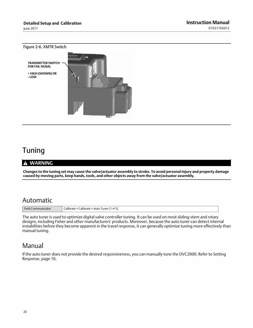
A switch is located on the options board to select the transmitter fail signal (high+ or low-). High+ will result in acurrent output of > 22.5 mA upon transmitter failure. Low- will result in a current output of < 3.6 mA. Refer tofigure 2‐6 for location and switch selection.
Instruction ManualD103176X012
Detailed Setup and CalibrationJune 2017
26
Figure 2‐6. XMTR Switch
TRANSMITTER SWITCHFOR FAIL SIGNAL
+ HIGH (SHOWN) OR- LOW
Tuning
WARNING
Changes to the tuning set may cause the valve/actuator assembly to stroke. To avoid personal injury and property damagecaused by moving parts, keep hands, tools, and other objects away from the valve/actuator assembly.
AutomaticField Communicator Calibrate > Calibrate > Auto Tuner (1-4-5)
The auto tuner is used to optimize digital valve controller tuning. It can be used on most sliding-stem and rotarydesigns, including Fisher and other manufacturers' products. Moreover, because the auto tuner can detect internalinstabilities before they become apparent in the travel response, it can generally optimize tuning more effectively thanmanual tuning.
ManualIf the auto tuner does not provide the desired responsiveness, you can manually tune the DVC2000. Refer to SettingResponse, page 16.
Instruction ManualD103176X012
Detailed Setup and CalibrationJune 2017
27
CalibrationField Communicator Calibrate > Calibrate (1-4)
WARNING
During calibration the valve will move full stroke. To avoid personal injury and property damage caused by the release ofpressure or process fluid, isolate the valve from the process and equalize pressure on both sides of the valve or bleed off theprocess fluid.
Note
If optional limit switches are being used, power must be applied to the switch circuits throughout the calibration routine. Failure topower the switches may result in incorrect switch orientation.
Analog Input Calibration The DVC2000 digital valve controller is shipped from the factory with the analog input already calibrated. You do notnormally need to perform this procedure. However, if you suspect that this needs adjustment, follow one of theprocedures below.
Using the Field Communicator to perform Analog Input Calibration
To calibrate the analog input sensor, connect a variable current source to the instrument LOOP+ and LOOP- terminals.The current source should be capable of generating an output of 4 to 20 mA. Select Analog In Calib from the Calibratemenu, then follow the prompts on the Field Communicator display to calibrate the analog input sensor.
1. Set the current source to the target value shown on the display. The target value is the Input Range Low value. PressOK.
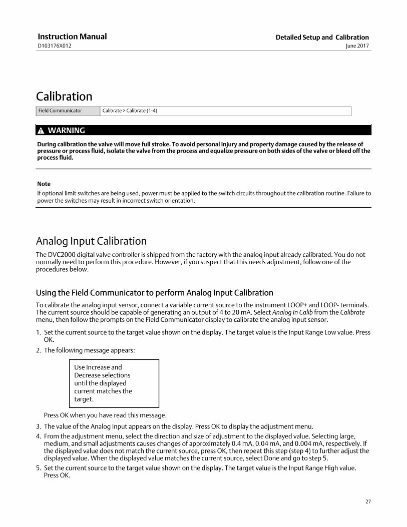
2. The following message appears:
Use Increase andDecrease selectionsuntil the displayedcurrent matches thetarget.
Press OK when you have read this message.
3. The value of the Analog Input appears on the display. Press OK to display the adjustment menu.
4. From the adjustment menu, select the direction and size of adjustment to the displayed value. Selecting large,medium, and small adjustments causes changes of approximately 0.4 mA, 0.04 mA, and 0.004 mA, respectively. Ifthe displayed value does not match the current source, press OK, then repeat this step (step 4) to further adjust thedisplayed value. When the displayed value matches the current source, select Done and go to step 5.
5. Set the current source to the target value shown on the display. The target value is the Input Range High value.Press OK.
Instruction ManualD103176X012
Detailed Setup and CalibrationJune 2017
28
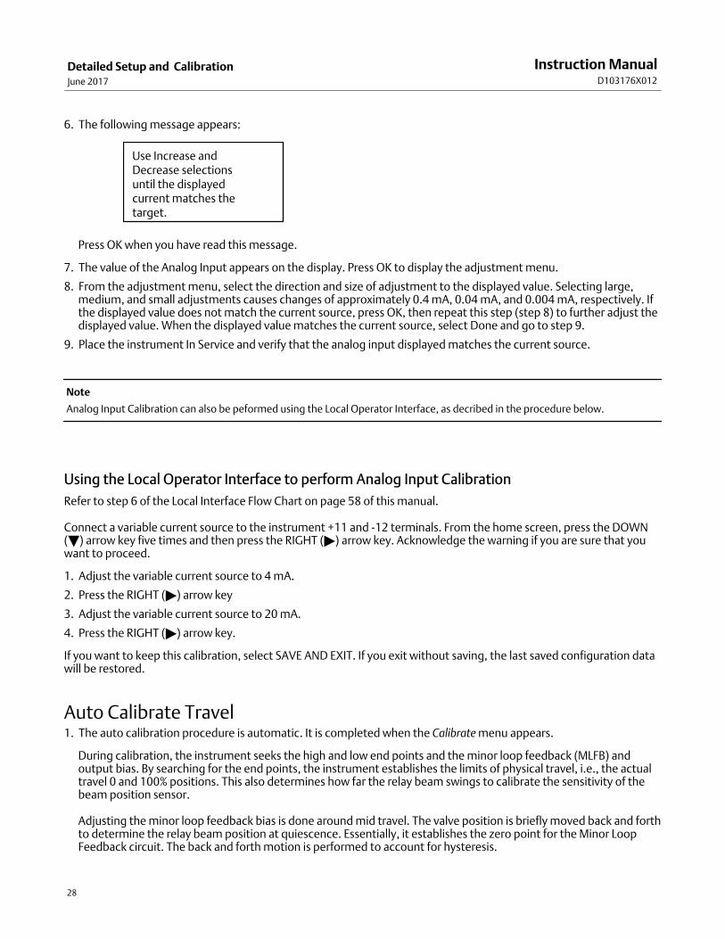
6. The following message appears:
Use Increase and Decrease selectionsuntil the displayed current matches the target.
Press OK when you have read this message.
7. The value of the Analog Input appears on the display. Press OK to display the adjustment menu.
8. From the adjustment menu, select the direction and size of adjustment to the displayed value. Selecting large,medium, and small adjustments causes changes of approximately 0.4 mA, 0.04 mA, and 0.004 mA, respectively. Ifthe displayed value does not match the current source, press OK, then repeat this step (step 8) to further adjust thedisplayed value. When the displayed value matches the current source, select Done and go to step 9.
9. Place the instrument In Service and verify that the analog input displayed matches the current source.
Note
Analog Input Calibration can also be peformed using the Local Operator Interface, as decribed in the procedure below.
Using the Local Operator Interface to perform Analog Input Calibration
Refer to step 6 of the Local Interface Flow Chart on page 58 of this manual.
Connect a variable current source to the instrument +11 and -12 terminals. From the home screen, press the DOWN(�) arrow key five times and then press the RIGHT () arrow key. Acknowledge the warning if you are sure that youwant to proceed.
1. Adjust the variable current source to 4 mA.
2. Press the RIGHT () arrow key
3. Adjust the variable current source to 20 mA.
4. Press the RIGHT () arrow key.
If you want to keep this calibration, select SAVE AND EXIT. If you exit without saving, the last saved configuration datawill be restored.
Auto Calibrate Travel 1. The auto calibration procedure is automatic. It is completed when the Calibrate menu appears.
During calibration, the instrument seeks the high and low end points and the minor loop feedback (MLFB) andoutput bias. By searching for the end points, the instrument establishes the limits of physical travel, i.e., the actualtravel 0 and 100% positions. This also determines how far the relay beam swings to calibrate the sensitivity of thebeam position sensor.
Adjusting the minor loop feedback bias is done around mid travel. The valve position is briefly moved back and forthto determine the relay beam position at quiescence. Essentially, it establishes the zero point for the Minor LoopFeedback circuit. The back and forth motion is performed to account for hysteresis.
Instruction ManualD103176X012
Detailed Setup and CalibrationJune 2017
29
Adjusting the output bias aligns the travel set point with the actual travel by computing the drive signal required toproduce 0% error. This is done while the valve is at 50% travel, making very small adjustments.
2. Place the instrument In Service and verify that the travel properly tracks the current source.
Manual Calibrate Travel Two procedures are available to manually calibrate travel:
� Analog Adjust
� Digital Adjust
Analog Calibration Adjust
Connect a variable current source to the instrument LOOP + and LOOP - terminals. The current source should becapable of generating 4 to 20 mA. Follow the prompts on the Field Communicator display to calibrate the instrument'stravel in percent.
Note
0% Travel = Valve Closed100% Travel = Valve Open
1. Adjust the input current until the valve is near mid-travel. Press OK.
Note
In steps 2 through 4, the accuracy of the current source adjustment affects the position accuracy.
2. Adjust the current source until the valve is at 0% travel, then press OK.
3. Adjust the current source until the valve is at 100% travel, then press OK.
4. Adjust the current source until the valve is at 50% travel, then press OK.
5. Place the instrument In Service and verify that the travel properly tracks the current source.
Digital Calibration Adjust
Connect a variable current source to the instrument LOOP + and LOOP - terminals. The current source should be setbetween 4 and 20 mA. Follow the prompts on the Field Communicator display to calibrate the instrument's travel inpercent.
Note
0% Travel = Valve Closed100% Travel = Valve Open
Instruction ManualD103176X012
Detailed Setup and CalibrationJune 2017
30
1. From the adjustment menu, select the direction and size of change required to set the travel at 0%.
If another adjustment is required, repeat step 1. Otherwise, select Done and go to step 2.
2. From the adjustment menu, select the direction and size of change required to set the travel to 100%.
If another adjustment is required, repeat step 2. Otherwise, select Done and go to step 3.
3. From the adjustment menu, select the direction and size of change required to set the travel to 50%.
If another adjustment is required, repeat step 3. Otherwise, select Done and go to step 4.
4. Place the instrument In Service and verify that the travel properly tracks the current source.
Pressure Sensor Calibration
Note
The pressure sensor is calibrated at the factory and should not require calibration.
Output Pressure Sensor Calibration
To calibrate the output pressure sensor, connect an external reference gauge to the output being calibrated. Thegauge should be capable of measuring maximum instrument supply pressure. From the Calibrate menu, select PressureCalib. Follow the prompts on the Field Communicator display to calibrate the instrument's output pressure sensor.
1. Adjust the supply pressure regulator to the maximum instrument supply pressure. Press OK.
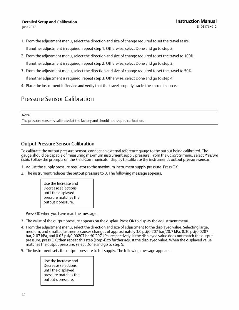
2. The instrument reduces the output pressure to 0. The following message appears.
Use the Increase andDecrease selectionsuntil the displayedpressure matches theoutput x pressure.
Press OK when you have read the message.
3. The value of the output pressure appears on the display. Press OK to display the adjustment menu.
4. From the adjustment menu, select the direction and size of adjustment to the displayed value. Selecting large,medium, and small adjustments causes changes of approximately 3.0 psi/0.207 bar/20.7 kPa, 0.30 psi/0.0207bar/2.07 kPa, and 0.03 psi/0.00207 bar/0.207 kPa, respectively. If the displayed value does not match the outputpressure, press OK, then repeat this step (step 4) to further adjust the displayed value. When the displayed valuematches the output pressure, select Done and go to step 5.
5. The instrument sets the output pressure to full supply. The following message appears.
Use the Increase andDecrease selectionsuntil the displayedpressure matches theoutput x pressure.

Instruction ManualD103176X012
Detailed Setup and CalibrationJune 2017
31
Press OK when you have read the message.
6. The value of the output pressure appears on the display. Press OK to display the adjustment menu.
7. From the adjustment menu, select the direction and size of adjustment to the displayed value. Selecting large,medium, and small adjustments causes changes of approximately 3.0 psi/0.207 bar/20.7 kPa, 0.30 psi/0.0207bar/2.07 kPa, and 0.03 psi/0.00207 bar/0.207 kPa, respectively. If the displayed value does not match the outputpressure, press OK, then repeat this step (step 7) to further adjust the displayed value. When the displayed valuematches the output pressure, select Done and go to step 8.
8. Place the instrument In Service and verify that the displayed pressure matches the measured output pressure.
Position Transmitter Calibration
Note
The position transmitter is calibrated at the factory and should not require calibration.
Note
This procedure will not move the control valve. The instrument will simulate an output for calibration purposes only.
This procedure is only available on units that have the optional position transmitter / limit switch hardware installed.The DVC2000 digital valve controller is shipped from the factory with the position transmitter already calibrated.
To calibrate the position transmitter, select Transmitter Calibration from the Calibrate menu. Connect a current meterin series with the +31 and -32 terminals, and a voltage source (such as the DCS analog input channel). Follow theprompts on the Field Communicator display to manipulate the output current read by the current meter to 4 mA, andthen to 20 mA.
Instruction ManualD103176X012
Detailed Setup and CalibrationJune 2017
32
Instruction ManualD103176X012
Viewing Device Variables and DiagnosticsJune 2017
33
Section 3 Viewing Device Variables and Diagnostics3‐3‐
Viewing Variables
Note
These variables are not available for instrument level AC.
Analog Input, Travel, Valve Set Point, Drive Signal and Output PressureThe following variables are displayed on the Online menu:
Analog In shows the value of the instrument analog input in mA (milliamperes) or % (percent) of ranged input.
Travel shows the value of the DVC2000 digital valve controller travel in % (percent) of ranged travel. Travel alwaysrepresents how far the valve is open.
Valve SP shows the requested valve position in % of ranged travel.
Drive Sgl shows the value of the instrument drive signal in % (percent) of maximum drive.
Pressure shows the value of the instrument output pressure in psi, bar, or kPa.
Additional Instrument VariablesField Communicator Setup & Diag > Display > Variables (1-3-1)
Note
These variables are not available for instrument level AC.
The Variables menu is available to view additional variables, such as the status of the auxiliary input, the instrumentinternal temperature, cycle count, travel accumulation and device free time. If a value for a variable does not appearon the display, select the variable and a detailed display of that variable with its value will appear. A variable's valuedoes not appear on the menu if the value becomes too large to fit in the allocated space on the display, or if thevariable requires special processing.
� Temp—The internal temperature of the instrument is displayed in either degrees Fahrenheit or Celsius.
� Cycl Count—Cycle Counter displays the number of times the valve travel has cycled. Only changes in direction of thetravel after the travel has exceeded the deadband are counted as a cycle. Once a new cycle has occurred, a newdeadband around the last travel is set. The value of the Cycle Counter can be reset from the Cycle Count Alert menu.
Instruction ManualD103176X012
Viewing Device Variables and DiagnosticsJune 2017
34
� Tvl Accum—Travel Accumulator contains the total change in travel, in percent of ranged travel. The accumulatoronly increments when travel exceeds the deadband. Then the greatest amount of change in one direction from theoriginal reference point (after the deadband has been exceeded) will be added to the Travel Accumulator. The valueof the Travel Accumulator can be reset from the Travel Accum Alert menu.
Viewing Device InformationField Communicator Setup & Diag > Display > Device Information (1-3-2)
The Device Information menu is available to view information about the instrument.
Follow the prompts on the Field Communicator display to view information in the following fields:
� HART Univ Rev—HART Universal Revision is the revision number of the HART Universal Commands which are used asthe communications protocol for the instrument.
� Device Rev—Device Revision is the revision number of the software for communication between the FieldCommunicator and the instrument.
� Firmware Rev—Firmware Revision is the revision number of the Fisher firmware in the instrument.
� Firmware Date—Firmware Date is the revision date of the firmware being used.
� Main Elec Rev—Main Electronics Revision is the revision number of the main electronics component.
� Sec Elec Rev—Secondary Electronics Revision is the revision number of the secondary electronics component.
� Sensor Serial Num—Sensor Serial Number is the serial number of the sensor
� Inst Level—Indicates the instrument level AC—Auto CalibrateHC—HART CommunicatingAD—Advanced DiagnosticsPD—Performance Diagnostic
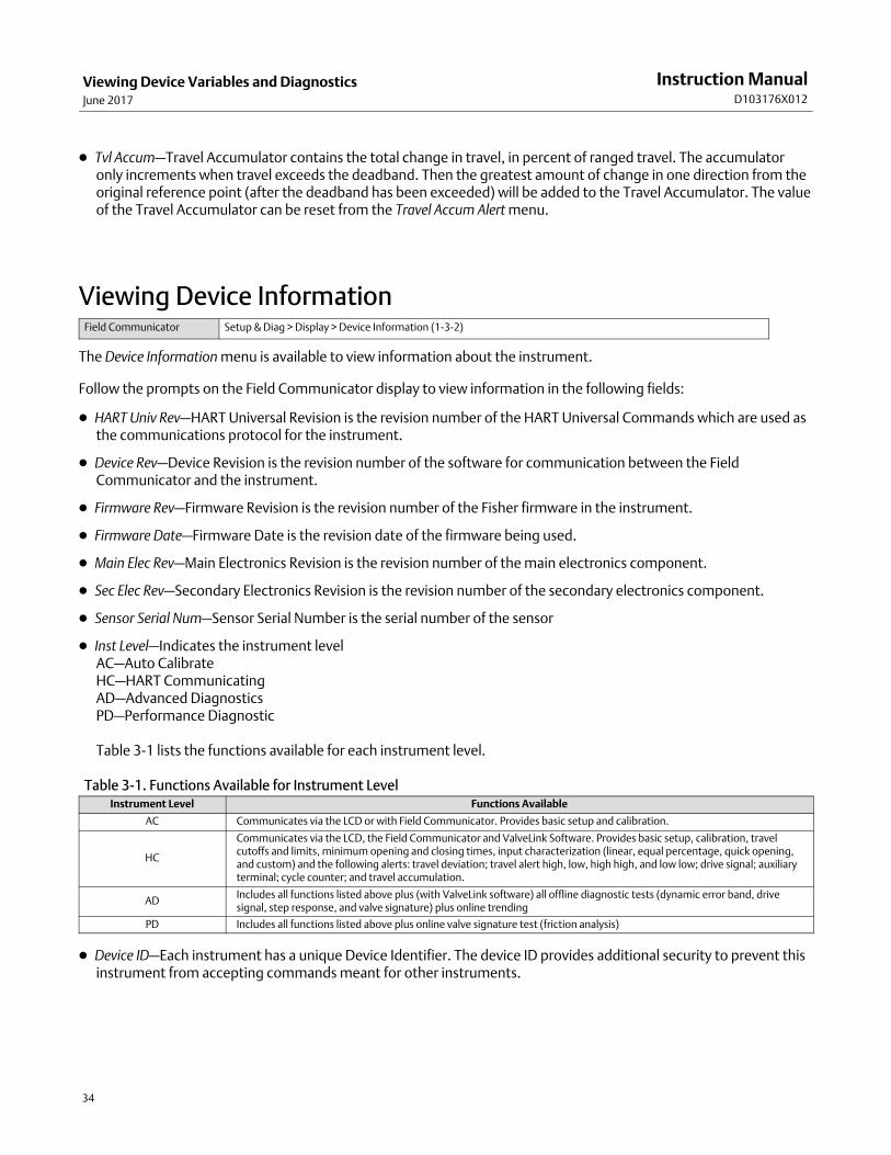
Table 3‐1 lists the functions available for each instrument level.
Table 3‐1. Functions Available for Instrument LevelInstrument Level Functions Available
AC Communicates via the LCD or with Field Communicator. Provides basic setup and calibration.
HC
Communicates via the LCD, the Field Communicator and ValveLink Software. Provides basic setup, calibration, travelcutoffs and limits, minimum opening and closing times, input characterization (linear, equal percentage, quick opening,and custom) and the following alerts: travel deviation; travel alert high, low, high high, and low low; drive signal; auxiliaryterminal; cycle counter; and travel accumulation.
ADIncludes all functions listed above plus (with ValveLink software) all offline diagnostic tests (dynamic error band, drivesignal, step response, and valve signature) plus online trending
PD Includes all functions listed above plus online valve signature test (friction analysis)
� Device ID—Each instrument has a unique Device Identifier. The device ID provides additional security to prevent thisinstrument from accepting commands meant for other instruments.
Instruction ManualD103176X012
Viewing Device Variables and DiagnosticsJune 2017
35
Viewing Instrument StatusField Communicator Instrument Status (7)
Note
Instrument Status is not available for instrument level AC.
The following describes the various displays for the Instrument Status menu.
� Done—Select this when you are done viewing the instrument status.
Note
Alerts are not available with instrument level AC.
� Valve Alerts—If a valve alert is active, it will appear when the Valve Alerts menu item is selected. If more than onealert is active, they will appear on the display one at a time in the order listed below.
1. Alert Record has Entries
2. Alert Record is full
3. Instrument Time is Invalid
4. Tvl Accumulation Alert
5. Cycle Counter Alert
6. Non-critical NVM Alert
7. Power Starvation Alert
8. Drive Signal Alert
9. Tvl Lim/Cutoff Low
10. Tvl Lim/Cutoff High
11. Tvl Deviation Alrt
12. Tvl Alert Hi Hi
13. Tvl Alert Hi
14. Tvl Alert Lo Lo
15. Tvl Alert Lo
Instruction ManualD103176X012
Viewing Device Variables and DiagnosticsJune 2017
36
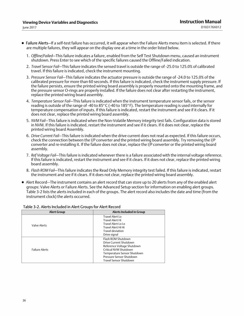
� Failure Alerts—If a self-test failure has occurred, it will appear when the Failure Alerts menu item is selected. If thereare multiple failures, they will appear on the display one at a time in the order listed below.
1. Offline/Failed—This failure indicates a failure, enabled from the Self Test Shutdown menu, caused an instrumentshutdown. Press Enter to see which of the specific failures caused the Offline/Failed indication.
2. Travel Sensor Fail—This failure indicates the sensed travel is outside the range of -25.0 to 125.0% of calibratedtravel. If this failure is indicated, check the instrument mounting.
3. Pressure Sensor Fail—This failure indicates the actuator pressure is outside the range of -24.0 to 125.0% of thecalibrated pressure for more than 60 seconds. If this failure is indicated, check the instrument supply pressure. Ifthe failure persists, ensure the printed wiring board assembly is properly mounted onto the mounting frame, andthe pressure sensor O-rings are properly installed. If the failure does not clear after restarting the instrument,replace the printed wiring board assembly.
4. Temperature Sensor Fail—This failure is indicated when the instrument temperature sensor fails, or the sensorreading is outside of the range of -40 to 85°C (-40 to 185°F). The temperature reading is used internally fortemperature compensation of inputs. If this failure is indicated, restart the instrument and see if it clears. If itdoes not clear, replace the printed wiring board assembly.
5. NVM Fail—This failure is indicated when the Non-Volatile Memory integrity test fails. Configuration data is storedin NVM. If this failure is indicated, restart the instrument and see if it clears. If it does not clear, replace theprinted wiring board Assembly.
6. Drive Current Fail—This failure is indicated when the drive current does not read as expected. If this failure occurs,check the connection between the I/P converter and the printed wiring board assembly. Try removing the I/Pconverter and re-installing it. If the failure does not clear, replace the I/P converter or the printed wiring boardassembly.
7. Ref Voltage Fail—This failure is indicated whenever there is a failure associated with the internal voltage reference.If this failure is indicated, restart the instrument and see if it clears. If it does not clear, replace the printed wiringboard assembly.
8. Flash ROM Fail—This failure indicates the Read Only Memory integrity test failed. If this failure is indicated, restartthe instrument and see if it clears. If it does not clear, replace the printed wiring board assembly.
� Alert Record—The instrument contains an alert record that can store up to 20 alerts from any of the enabled alertgroups: Valve Alerts or Failure Alerts. See the Advanced Setup section for information on enabling alert groups.Table 3‐2 lists the alerts included in each of the groups. The alert record also includes the date and time (from theinstrument clock) the alerts occurred.
Table 3‐2. Alerts Included in Alert Groups for Alert RecordAlert Group Alerts Included in Group
Valve Alerts
Travel Alert LoTravel Alert HiTravel Alert Lo LoTravel Alert Hi HiTravel deviationDrive signal
Failure Alerts
Flash ROM ShutdownDrive Current ShutdownReference Voltage ShutdownCritical NVM ShutdownTemperature Sensor ShutdownPressure Sensor ShutdownTravel Sensor Shutdown
Instruction ManualD103176X012
Viewing Device Variables and DiagnosticsJune 2017
37
� Operational Status—This menu item indicates the status of the Operational items listed below. The status of morethan one operational may be indicated. If more than one Operational status is set, they will appear on the displayone at a time in the order listed below.
1. Out of Service
2. Auto Calibration in Progress
3. Input Char Selected
4. Custom Char Selected
5. Diagnostic in Progress
6. Calibration in Progress
7. Set Point Filter Active

Instruction ManualD103176X012
Viewing Device Variables and DiagnosticsJune 2017
38
Maintenance and TroubleshootingJune 2017
Instruction ManualD103176X012
39
Section 4 Maintenance and Troubleshooting4‐4‐
The DVC2000 digital valve controller has the capability to provide predictive maintenance information through theuse of ValveLink software. This software allows you to pinpoint instrument and valve problems without disrupting theprocess. For information on using ValveLink software, see the ValveLink software quick start guide (D102813X012).
WARNING
Avoid personal injury or property damage from sudden release of process pressure or bursting of parts. Before performingany maintenance procedures on the the DVC2000 digital valve controller:
� Always wear protective clothing, gloves, and eyewear when performing any maintenance procedures to avoid personalinjury or property damage.
� Do not remove the actuator from the valve while the valve is still pressurized.
� Disconnect any operating lines providing air pressure, electric power, or a control signal to the actuator. Be sure theactuator cannot suddenly open or close the control valve.
� Use bypass valves or completely shut off the process to isolate the control valve from process pressure. Relieve processpressure from both sides of the control valve.
� Use lock-out procedures to be sure that the above measures stay in effect while you work on the equipment.
� Check with your process or safety engineer for any additional measures that must be taken to protect against processmedia.
� Vent the pneumatic actuator loading pressure and relieve any actuator spring precompression so the actuator is notapplying force to the valve stem; this will allow for the safe removal of the stem connector.
CAUTION
When replacing components, use only components specified by the factory. Always use proper component replacementtechniques, as presented in this manual. Improper techniques or component selection may invalidate the approvals andthe product specifications, as indicated in table 1‐1 and may also impair operations and the intended function of the device.
Stroking the Digital Valve Controller OutputField Communicator Setup & Diag > Stroke Valve (1-5)
Note
Stroke Valve is not available with instrument level AC.
Follow the prompts on the Field Communicator display to select from the following: Done, Ramp Open, Ramp Closed,Ramp to Target, and Step to Target, and Stop.
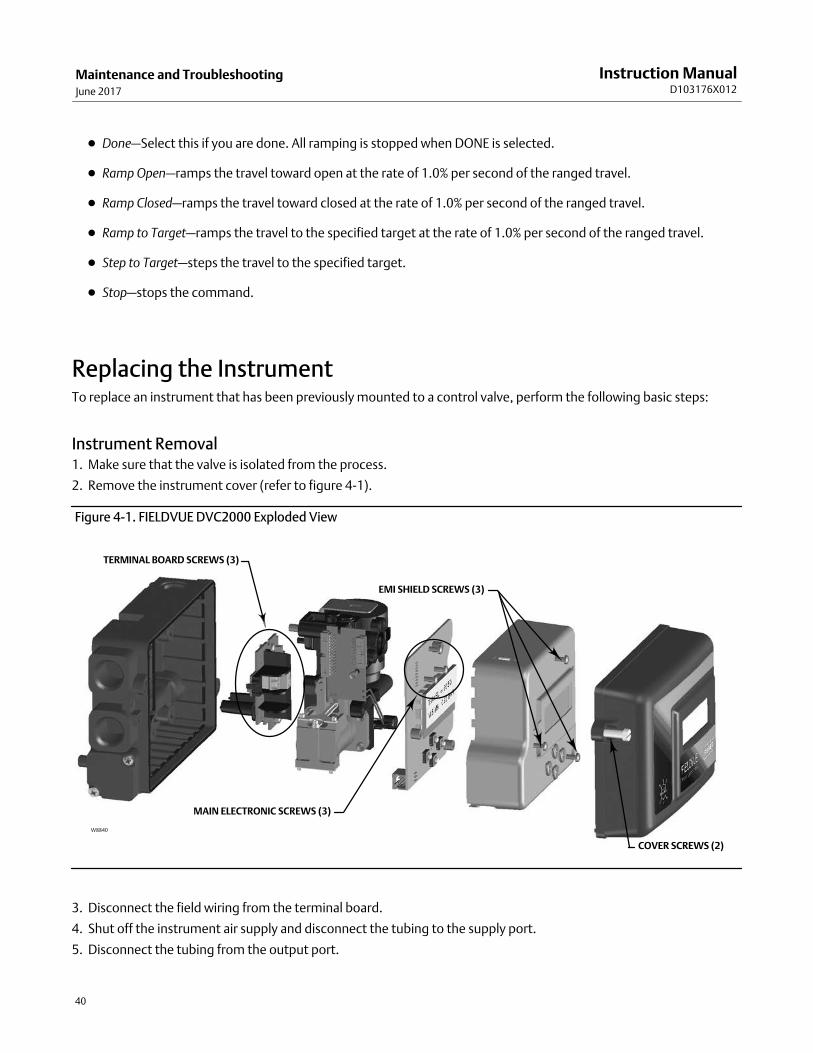
Maintenance and TroubleshootingJune 2017
Instruction ManualD103176X012
40
� Done—Select this if you are done. All ramping is stopped when DONE is selected.
� Ramp Open—ramps the travel toward open at the rate of 1.0% per second of the ranged travel.
� Ramp Closed—ramps the travel toward closed at the rate of 1.0% per second of the ranged travel.
� Ramp to Target—ramps the travel to the specified target at the rate of 1.0% per second of the ranged travel.
� Step to Target—steps the travel to the specified target.
� Stop—stops the command.
Replacing the Instrument To replace an instrument that has been previously mounted to a control valve, perform the following basic steps:
Instrument Removal 1. Make sure that the valve is isolated from the process.
2. Remove the instrument cover (refer to figure 4‐1).
Figure 4‐1. FIELDVUE DVC2000 Exploded View
TERMINAL BOARD SCREWS (3)
EMI SHIELD SCREWS (3)
COVER SCREWS (2)
MAIN ELECTRONIC SCREWS (3)
W8840
3. Disconnect the field wiring from the terminal board.
4. Shut off the instrument air supply and disconnect the tubing to the supply port.
5. Disconnect the tubing from the output port.
Maintenance and TroubleshootingJune 2017
Instruction ManualD103176X012
41
6. Remove the bolts connecting the DVC2000 housing to the mounting bracket.
Note
The magnet assembly may remain on the valve stem (or shaft).
When replacing the instrument, be sure to follow the mounting procedure outlined in the quick start guide(D103203X012) that shipped with the digital valve controller. Once the instrument is mounted, perform the QuickSetup routine outlined in the quick start guide. If changes need to be made to the default settings, use Detailed Setupto make the appropriate modifications.
Replacing the Magnetic Feedback Assembly To remove the magnet assembly from the actuator stem, perform the following basic steps.
1. Make sure that the valve is isolated from the process.
2. Remove the instrument cover.
3. Disconnect the field wiring from the terminal board.
4. Shut off the instrument air supply.
5. Remove the DVC2000 from the actuator.
6. Remove the screws holding the magnet assembly to the connector arm.
When replacing the instrument, be sure to follow the mounting procedure outlined in the quick start guide thatshipped with the digital valve controller. Once the instrument is mounted, perform the Quick Setup routine outlined inthe quick start guide. If changes need to be made to the default settings, use Detailed Setup to make the appropriatemodifications.
Component Replacement When replacing any of the components of the DVC2000, the maintenance should be performed in an instrument shopwhenever possible. Make sure that the electrical wiring and pneumatic tubing is disconnected prior to disassemblingthe instrument.
CAUTION
When replacing components, proper means of electrostatic discharge protection is required. Failure to use a groundingstrap, or other means of electrostatic discharge protection can result in damage to the electronics.
Replacing the I/P Converter The I/P converter is fastened to the mounting frame. On the I/P mounting surface is a replaceable screen with O-ringseal.
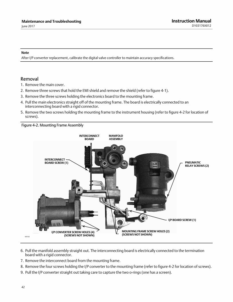
Maintenance and TroubleshootingJune 2017
Instruction ManualD103176X012
42
Note
After I/P converter replacement, calibrate the digital valve controller to maintain accuracy specifications.
Removal 1. Remove the main cover.
2. Remove three screws that hold the EMI shield and remove the shield (refer to figure 4‐1).
3. Remove the three screws holding the electronics board to the mounting frame.
4. Pull the main electronics straight off of the mounting frame. The board is electrically connected to aninterconnecting board with a rigid connector.
5. Remove the two screws holding the mounting frame to the instrument housing (refer to figure 4‐2 for location ofscrews).
Figure 4‐2. Mounting Frame Assembly
INTERCONNECTBOARD SCREW (1)
I/P CONVERTER SCREW HOLES (4)(SCREWS NOT SHOWN)
MOUNTING FRAME SCREW HOLES (2)(SCREWS NOT SHOWN)
I/P BOARD SCREW (1)
PNEUMATICRELAY SCREWS (2)
MANIFOLDASSEMBLY
INTERCONNECTBOARD
W9103
6. Pull the manifold assembly straight out. The interconnecting board is electrically connected to the terminationboard with a rigid connector.
7. Remove the interconnect board from the mounting frame.
8. Remove the four screws holding the I/P converter to the mounting frame (refer to figure 4‐2 for location of screws).
9. Pull the I/P converter straight out taking care to capture the two o-rings (one has a screen).
Maintenance and TroubleshootingJune 2017
Instruction ManualD103176X012
43
Assembly
When installing a new I/P converter, follow the reverse procedure as outlined above and recalibrate the instrument.
1. Install the I/P converter, making sure the screen O-ring is installed on the I/P supply port (the circular port on themounting frame), and that the two manifold O-rings are in place.
2. Install the interconnect board on the mounting frame. Do not tighten the self-tapping screw on on the interconnectboard at this time (see figure 4‐2).
3. Replace the manifold assembly.
4. Install the mounting frame to the housing, making sure that the O-rings (keys 45 and 51) are in place.
5. Install the main electronics to the mounting frame, making sure that the pressure sensor seal (key 16) is in place.
6. Tighten the self-tapping screw on the Interconnect Board.
7. Install the primary shield (key 37) with three screws.
8. Recalibrate the instrument and install the cover.
Replacing the Pneumatic Relay The pneumatic relay is fastened to the mounting frame. There are two versions, 0 to 3.4 bar (0 to 49 psig), indicated bya white label, and 3.5 to 7 bar (50 to 100 psig), indicated by a green label.
Note
After pneumatic relay replacement, calibrate the digital valve controller to maintain accuracy specifications.
Removal 1. Remove the main cover.
2. Remove three screws that hold the EMI shield and remove the shield (refer to figure 4‐1).
3. Remove the three screws holding the electronics board to the mounting frame.
4. Pull the main electronics straight off of the mounting frame. The board is electrically connected to aninterconnecting board with a rigid connector.
5. Remove the two screws holding the mounting frame to the instrument housing (refer to figure 4‐2).
6. Pull the mounting frame straight out. The interconnecting board is electrically connected to the termination boardwith a rigid connector.
7. Remove the two screws holding the pneumatic relay to the mounting frame.
8. Pull the pneumatic relay straight out.
Assembly
When installing a new pneumatic relay, follow the reverse procedure as outlined above and recalibrate the instrument.
Maintenance and TroubleshootingJune 2017
Instruction ManualD103176X012
44
Troubleshooting
What is a healthy unit?
In order to troubleshoot the DVC2000 digital valve controller, it is critical to understand how a healthy unit is supposedto behave. Below is a list of behaviors you should see if the instrument is performing well.
� LCD correctly displaying characters
� Pushbuttons allow navigation
� Valve travels full stroke
� No diagnostics messages
� No alerts or alarms
� Hall sensor within the valid range of travel on the magnet array
� Slight audible air venting
� Minimal overshoot
� Quick response
� Functionality matches the tier level
What are the observable symptoms?
The next thing to do is to identify the symptoms of the unhealthy unit. Are there any obvious discrepancies that can beidentified? Work through the following items to help gather information about the faulty behavior and identify thecore problem(s). Also see the DVC2000 Troubleshooting Checklist on page 47.
1. Check the relay pressure range.
There are two available relays for the DVC2000:
� Low pressure: 0-3.4 bar (0-49 psi) — white label
� High pressure: 3.5-7 bar (50-100 psi) — green label
The supply pressure feeding the instrument must fall within the rated pressure range of the installed relay for properoperation.
2. Check the instrument protection (LCD via pushbuttons and Configure/Calibrate via HART)
3. Check for local device diagnostic messages
Maintenance and TroubleshootingJune 2017
Instruction ManualD103176X012
45
4. Check the alerts via HART
5. Check the feedback setup
Is the pole piece on the DVC2000 housing within the valid travel range of the feedback array?
6. Observe the stem movement and pressure delivery
Determine the logical causes.
With the discrepancies identified, logic can now be applied to isolate the component that is in need of repair orreplacement. There are seven main categories of problems:
1. Wiring and Terminations
2. Air Supply
3. Electronics
4. Firmware
5. Pneumatics
6. Travel feedback
7. Mounting
Repair or replace the faulty components.
By isolating the problem to one of these categories, component replacement or repair becomes simple andstraightforward. Refer to component replacement instructions earlier in this section.
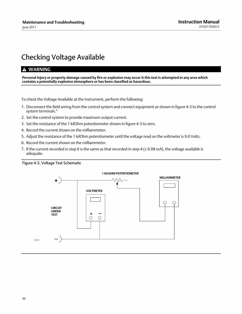
Maintenance and TroubleshootingJune 2017
Instruction ManualD103176X012
46
Checking Voltage Available
WARNING
Personal injury or property damage caused by fire or explosion may occur it this test is attempted in any area whichcontains a potentially explosive atmosphere or has been classified as hazardous.
To check the Voltage Available at the instrument, perform the following:
1. Disconnect the field wiring from the control system and connect equipment as shown in figure 4‐3 to the controlsystem terminals.”
2. Set the control system to provide maximum output current.
3. Set the resistance of the 1 kilOhm potentiometer shown in figure 4‐3 to zero.
4. Record the current shown on the milliammeter.
5. Adjust the resistance of the 1 kilOhm potentiometer until the voltage read on the voltmeter is 9.0 Volts.
6. Record the current shown on the milliammeter.
7. If the current recorded in step 6 is the same as that recorded in step 4 (± 0.08 mA), the voltage available isadequate.
Figure 4‐3. Voltage Test Schematic
CIRCUITUNDERTEST
VOLTMETER
MILLIAMMETER
1 KILOHM POTENTIOMETER
A6192-1
Maintenance and TroubleshootingJune 2017
Instruction ManualD103176X012
47
Technical Support ChecklistHave the following information available prior to contacting your Emerson sales office or Local Business Partner forsupport.
1. Instrument serial number as read from nameplate ________________________________________________
2. Is the digital valve controller responding to the control signal? Yes _________ No _________
If not, describe:
3. Measure the voltage across the “+11” and “-12” terminal box screws when the commanded current is 4.0 mA and20.0 mA: V @ 4.0 mA V @ 20.0 mA.(These values should be around 8.0 V @ 4.0 mA and 8.25 V @ 20 mA.)
4. Is the front panel LCD functional? Yes _________ No _________
5. Is it possible to communicate with the DVC2000 via the LUI pushbuttons? Yes _________ No _________
6. Are Travel, Input Signal, and Output Pressure in the LCD shown correctly? Yes _________ No _________
7. Is it possible to communicate via HART to the DVC2000? Yes _________ No _________
8. What is the Diagnostic Tier of the digital valve controller? AC ____ HC____ AD____ PD____
9. What is the firmware version of the DVC2000? _________________
10. What is the hardware version of the DVC2000? _________________
11. Is the digital valve controller's Instrument Mode “In Service”? Yes _________ No _________
12. Is the digital valve controller's Control Mode set to “Analog”? Yes _________ No _________
13. What are the following parameter readings?
Input Signal _________ Drive Signal _________% Pressure _________
Travel Target ________ Travel _________%
14. What are the following alert readings?
Fail alerts _______________________________________________________________________________
Valve alerts _____________________________________________________________________________
Operational status ________________________________________________________________________
Alert event record entries __________________________________________________________________
15. Export ValveLink data (if available) for the device (Status Monitor, Detailed Setup, etc.).
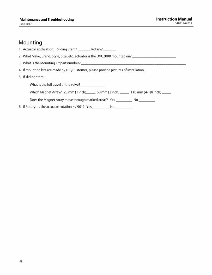
Maintenance and TroubleshootingJune 2017
Instruction ManualD103176X012
48
Mounting1. Actuator application: Sliding Stem? _______ Rotary? _______
2. What Make, Brand, Style, Size, etc. actuator is the DVC2000 mounted on? ________________________
3. What is the Mounting Kit part number? _________________________________________________________
4. If mounting kits are made by LBP/Customer, please provide pictures of installation.
5. If sliding stem:
What is the full travel of the valve? _____________
Which Magnet Array? 25 mm (1 inch)_____ 50 mm (2 inch) _____ 110 mm (4-1/8 inch) _____
Does the Magnet Array move through marked areas? Yes _________ No _________
6. If Rotary: Is the actuator rotation � 90�? Yes _________ No _________
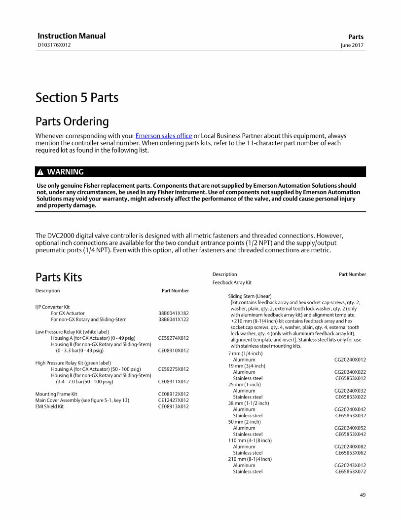
PartsJune 2017
Instruction ManualD103176X012
49
Section 5 Parts5‐5‐
Parts Ordering Whenever corresponding with your Emerson sales office or Local Business Partner about this equipment, alwaysmention the controller serial number. When ordering parts kits, refer to the 11-character part number of eachrequired kit as found in the following list.
WARNING
Use only genuine Fisher replacement parts. Components that are not supplied by Emerson Automation Solutions shouldnot, under any circumstances, be used in any Fisher instrument. Use of components not supplied by Emerson AutomationSolutions may void your warranty, might adversely affect the performance of the valve, and could cause personal injuryand property damage.
The DVC2000 digital valve controller is designed with all metric fasteners and threaded connections. However,optional inch connections are available for the two conduit entrance points (1/2 NPT) and the supply/outputpneumatic ports (1/4 NPT). Even with this option, all other fasteners and threaded connections are metric.
Parts Kits Description Part Number
I/P Converter Kit
For GX Actuator 38B6041X182
For non-GX Rotary and Sliding-Stem 38B6041X122
Low Pressure Relay Kit (white label)
Housing A (for GX Actuator) (0 - 49 psig) GE59274X012
Housing B (for nonGX Rotary and Sliding-Stem)
�(0 - 3.3 bar/0 - 49 psig) GE08910X012
High Pressure Relay Kit (green label)
Housing A (for GX Actuator) (50 - 100 psig) GE59275X012
Housing B (for nonGX Rotary and Sliding-Stem)
�(3.4 - 7.0 bar/50 - 100 psig) GE08911X012
Mounting Frame Kit GE08912X012
Main Cover Assembly (see figure 5‐1, key 13) GE12427X012
EMI Shield Kit GE08913X012
Description Part Number
Feedback Array Kit
Sliding Stem (Linear)
[kit contains feedback array and hex socket cap screws, qty. 2,
washer, plain, qty. 2, external tooth lock washer, qty. 2 (only
with aluminum feedback array kit) and alignment template.
•210 mm (8-1/4 inch) kit contains feedback array and hex
socket cap screws, qty. 4, washer, plain, qty. 4, external tooth
lock washer, qty. 4 (only with aluminum feedback array kit),
alignment template and insert]. Stainless steel kits only for use
with stainless steel mounting kits.
7 mm (1/4-inch)
Aluminum GG20240X012
19 mm (3/4-inch)
Aluminum GG20240X022
Stainless steel GE65853X012
25 mm (1-inch)
Aluminum GG20240X032
Stainless steel GE65853X022
38 mm (1-1/2 inch)
Aluminum GG20240X042
Stainless steel GE65853X032
50 mm (2-inch)
Aluminum GG20240X052
Stainless steel GE65853X042
110 mm (4-1/8 inch)
Aluminum GG20240X082
Stainless steel GE65853X062
210 mm (8-1/4 inch)
Aluminum GG20243X012
Stainless steel GE65853X072
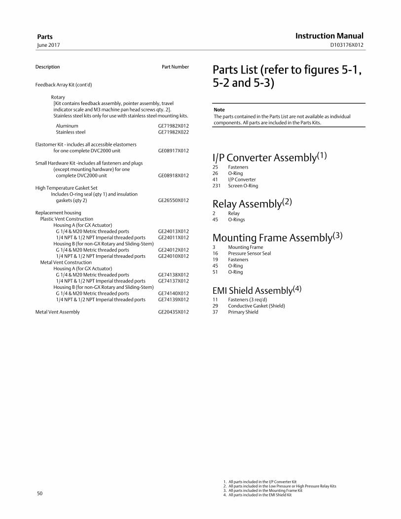
PartsJune 2017
Instruction ManualD103176X012
50
Description Part Number
Feedback Array Kit (cont'd)
Rotary
[Kit contains feedback assembly, pointer assembly, travel
indicator scale and M3 machine pan head screws qty. 2].
Stainless steel kits only for use with stainless steel mounting kits.
Aluminum GE71982X012
Stainless steel GE71982X022
Elastomer Kit - includes all accessible elastomers
for one complete DVC2000 unit GE08917X012
Small Hardware Kit -includes all fasteners and plugs
(except mounting hardware) for one
complete DVC2000 unit GE08918X012
High Temperature Gasket Set
Includes O-ring seal (qty 1) and insulation
gaskets (qty 2) GE26550X012
Replacement housing
Plastic Vent Construction
Housing A (for GX Actuator)
G 1/4 & M20 Metric threaded ports GE24013X012
1/4 NPT & 1/2 NPT Imperial threaded ports GE24011X012
Housing B (for nonGX Rotary and Sliding-Stem)
G 1/4 & M20 Metric threaded ports GE24012X012
1/4 NPT & 1/2 NPT Imperial threaded ports GE24010X012
Metal Vent Construction
Housing A (for GX Actuator)
G 1/4 & M20 Metric threaded ports GE74138X012
1/4 NPT & 1/2 NPT Imperial threaded ports GE74137X012
Housing B (for nonGX Rotary and Sliding-Stem)
G 1/4 & M20 Metric threaded ports GE74140X012
1/4 NPT & 1/2 NPT Imperial threaded ports GE74139X012
Metal Vent Assembly GE20435X012
Parts List (refer to figures 5‐1,5‐2 and 5‐3)
Note
The parts contained in the Parts List are not available as individual
components. All parts are included in the Parts Kits.
I/P Converter Assembly(1)
25 Fasteners
26 O-Ring
41 I/P Converter
231 Screen O-Ring
Relay Assembly(2)
2 Relay
45 O-Rings
Mounting Frame Assembly(3)
3 Mounting Frame
16 Pressure Sensor Seal
19 Fasteners
45 O-Ring
51 O-Ring
EMI Shield Assembly(4)
11 Fasteners (3 req'd)
29 Conductive Gasket (Shield)
37 Primary Shield
1. All parts included in the I/P Converter Kit2. All parts included in the Low Pressure or High Pressure Relay Kits3. All parts included in the Mounting Frame Kit4. All parts included in the EMI Shield Kit
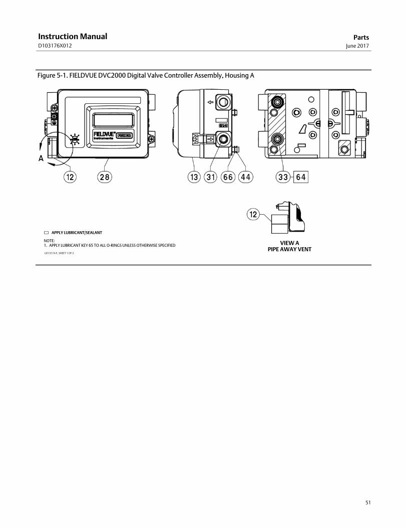
PartsJune 2017
Instruction ManualD103176X012
51
Figure 5‐1. FIELDVUE DVC2000 Digital Valve Controller Assembly, Housing A
APPLY LUBRICANT/SEALANT
NOTE:1. APPLY LUBRICANT KEY 65 TO ALL O-RINGS UNLESS OTHERWISE SPECIFIED VIEW A
PIPE AWAY VENTGE13174-F, SHEET 1 OF 3
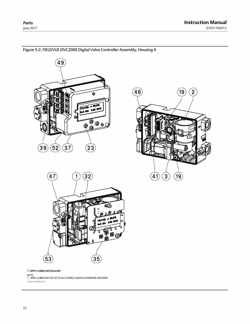
PartsJune 2017
Instruction ManualD103176X012
52
Figure 5‐2. FIELDVUE DVC2000 Digital Valve Controller Assembly, Housing A
GE13174-F, SHEET 2 OF 3
APPLY LUBRICANT/SEALANT
NOTE:1. APPLY LUBRICANT KEY 65 TO ALL O-RINGS UNLESS OTHERWISE SPECIFIED
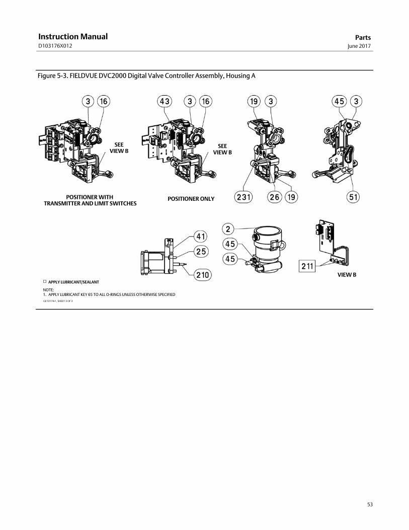
PartsJune 2017
Instruction ManualD103176X012
53
Figure 5‐3. FIELDVUE DVC2000 Digital Valve Controller Assembly, Housing A
POSITIONER ONLY
VIEW B
SEEVIEW B
SEEVIEW B
GE13174-F, SHEET 3 OF 3
APPLY LUBRICANT/SEALANT
NOTE:1. APPLY LUBRICANT KEY 65 TO ALL O-RINGS UNLESS OTHERWISE SPECIFIED
POSITIONER WITH TRANSMITTER AND LIMIT SWITCHES

PartsJune 2017
Instruction ManualD103176X012
54
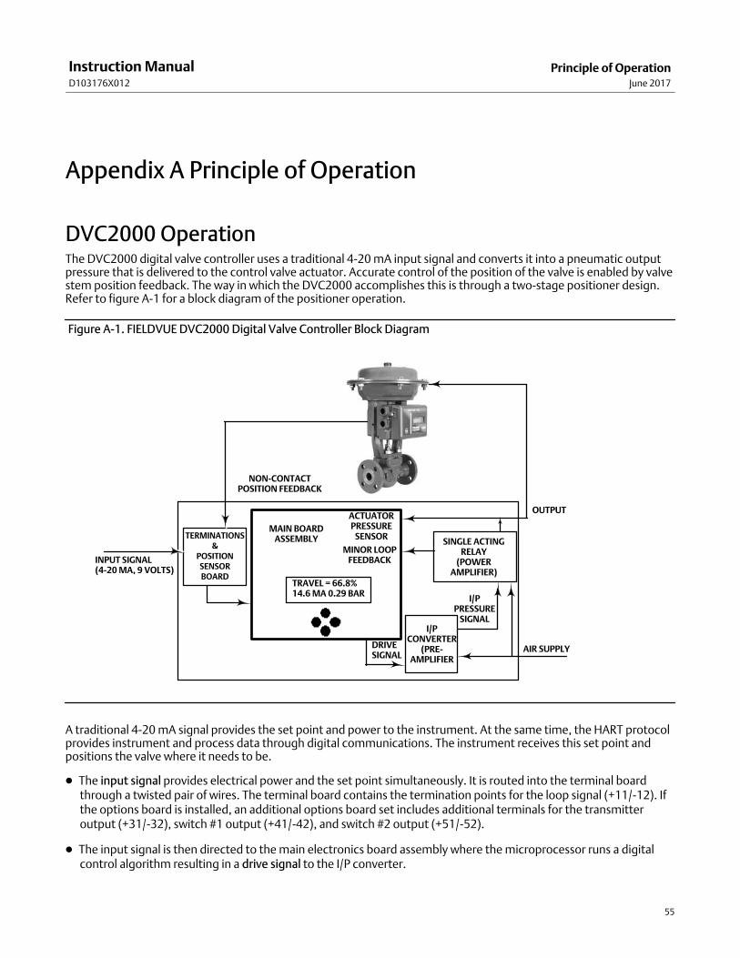
Principle of OperationJune 2017
Instruction ManualD103176X012
55
Appendix A Principle of OperationA‐1‐
DVC2000 Operation The DVC2000 digital valve controller uses a traditional 4-20 mA input signal and converts it into a pneumatic outputpressure that is delivered to the control valve actuator. Accurate control of the position of the valve is enabled by valvestem position feedback. The way in which the DVC2000 accomplishes this is through a two-stage positioner design.Refer to figure A‐1 for a block diagram of the positioner operation.
Figure A‐1. FIELDVUE DVC2000 Digital Valve Controller Block Diagram
INPUT SIGNAL(4-20 MA, 9 VOLTS)
TERMINATIONS&
POSITIONSENSORBOARD
MAIN BOARDASSEMBLY
ACTUATORPRESSURE
SENSOR
TRAVEL = 66.8%14.6 MA 0.29 BAR
MINOR LOOPFEEDBACK
DRIVESIGNAL
I/PCONVERTER
(PRE-AMPLIFIER
AIR SUPPLY
OUTPUT
SINGLE ACTINGRELAY
(POWERAMPLIFIER)
I/PPRESSURE
SIGNAL
NON-CONTACTPOSITION FEEDBACK
A traditional 4-20 mA signal provides the set point and power to the instrument. At the same time, the HART protocolprovides instrument and process data through digital communications. The instrument receives this set point andpositions the valve where it needs to be.
� The input signal provides electrical power and the set point simultaneously. It is routed into the terminal boardthrough a twisted pair of wires. The terminal board contains the termination points for the loop signal (+11/-12). Ifthe options board is installed, an additional options board set includes additional terminals for the transmitteroutput (+31/-32), switch #1 output (+41/-42), and switch #2 output (+51/-52).
� The input signal is then directed to the main electronics board assembly where the microprocessor runs a digitalcontrol algorithm resulting in a drive signal to the I/P converter.
Principle of OperationJune 2017
Instruction ManualD103176X012
56
� The I/P converter assembly is connected to supply pressure and converts the drive signal into a pressure signal. TheI/P converter is the pre-amplifier stage in the two-stage positioner design. This component enables high static gainfor responsiveness to small changes in the input signal.
� The I/P output is sent to the pneumatic relay assembly. The relay is also connected to supply pressure and amplifiesthe small pressure signal from the I/P converter into a larger pneumatic output signal used by the actuator. Thepneumatic relay is the power amplifier stage in the two-stage positioner design. This component enables superiordynamic performance with minimal steady-state air consumption.
� A sensor on the printed wiring board measures the motion of the small valve inside the pneumatic relay. Thismeasurement is used for minor loop feedback to the control algorithm resulting in stable, robust tuning.
� The change in relay output pressure to the actuator causes the valve to move.
� Valve position is sensed through the non-contact, linkage-less feedback sensor. There are no moving linkages andthe DVC2000 is physically separated from the valve stem through the use of a magnetic Hall effect sensor. Amagnetic array is mounted to the valve stem and the sensor is embedded in the DVC2000 housing. The sensor iselectrically connected to the printed wiring board to provide a travel feedback signal used in the control algorithm.
The valve continues to move until the correct position is attained.
Local Interface Flow Chart/Menu TreesJune 2017
Instruction ManualD103176X012
57
Appendix B Local Interface Flow Chart and Field CommunicatorMenu TreesB‐B‐
This section contains the Local Interface Flow Chart and the Field Communicator menu trees for instrument level HC,AD, and PD and instrument level AC. It also contains Fast Key Sequence tables with coordinates to help locate thefunction/variable on the appropriate menu tree.
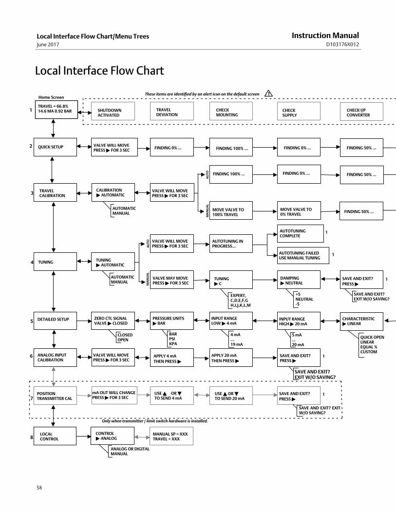
Local Interface Flow Chart/Menu TreesJune 2017
Instruction ManualD103176X012
58
Local Interface Flow Chart
TRAVEL = 66.8%14.6 MA 0.92 BAR
QUICK SETUP
�
�
�
�
�
�
�
TRAVELDEVIATION
CHECKMOUNTING
CHECKSUPPLY
CHECK I/PCONVERTER
VALVE WILL MOVEPRESS � FOR 3 SEC
FINDING 0% ... FINDING 100% ... FINDING 50% ...FINDING 0% ...
VALVE WILL MOVEPRESS � FOR 3 SEC
FINDING 100% ... FINDING 0% ... FINDING 50% ...
FINDING 50% ...
TRAVELCALIBRATION
TUNING
DETAILED SETUP
ANALOG INPUTCALIBRATION
POSITIONTRANSMITTER CAL
LOCALCONTROL
VALVE WILL MOVEPRESS � FOR 3 SEC
VALVE WILL MOVEPRESS � FOR 3 SEC
ZERO CTL SIGNALVALVE � CLOSED
PRESSURE UNITS� BAR
INPUT RANGELOW � 4 mA
INPUT RANGEHIGH � 20 mA
CHARACTERISTIC� LINEAR
SAVE AND EXIT?PRESS �
SAVE AND EXIT?
PRESS �
SAVE AND EXIT?
PRESS �
MOVE VALVE TO0% TRAVEL
MOVE VALVE TO100% TRAVEL
CALIBRATION � AUTOMATIC
TUNING� AUTOMATIC
AUTOTUNING INPROGRESS...
TUNING� C
APPLY 4 mA
THEN PRESS �
APPLY 20 mA
THEN PRESS �
VALVE MAY MOVEPRESS � FOR 3 SEC
SHUTDOWNACTIVATED
AUTOTUNINGCOMPLETE
AUTOTUNING FAILEDUSE MANUAL TUNING
DAMPING� NEUTRAL
mA OUT WILL CHANGEPRESS � FOR 3 SEC
USE � OR � TO SEND 4 mA
USE � OR �TO SEND 20 mA
CONTROL � ANALOG
MANUAL SP = XXXTRAVEL = XXX
ANALOG OR DIGITALMANUAL
SAVE AND EXIT? EXITW/O SAVING?
SAVE AND EXIT?EXIT W/O SAVING?
SAVE AND EXIT? EXIT W/O SAVING?
+5 NEUTRAL-5
EXPERT,C,D,E,F,GH,I,J,K,L,M
AUTOMATICMANUAL
BARPSIKPA
CLOSEDOPEN
4 mA...19 mA
5 mA...20 mA
QUICK OPENLINEAREQUAL %CUSTOM
AUTOMATICMANUAL
1
2
3
4
5
6
7
8
1
1
1
1
1
These items are identified by an alert icon on the default screen !
Only when transmitter / limit switch hardware is installed.
Home Screen
MA
NU
AL
AU
TO
MA
NU
AL
AU
TO
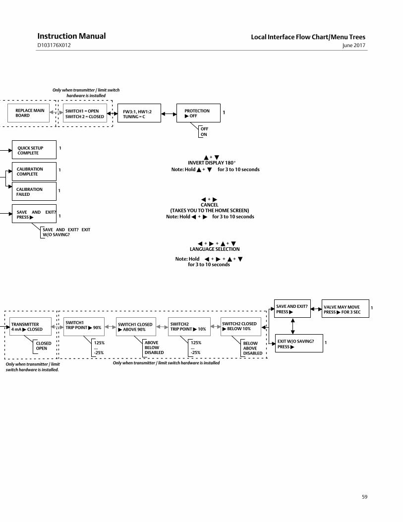
Local Interface Flow Chart/Menu TreesJune 2017
Instruction ManualD103176X012
59
VALVE MAY MOVE
PRESS � FOR 3 SEC
SAVE AND EXIT?
PRESS �
EXIT W/O SAVING?
PRESS �
SWITCH2 CLOSED� BELOW 10%
SWITCH1 CLOSED� ABOVE 90%
SWITCH2 TRIP POINT � 10%
SWITCH1 TRIP POINT � 90%
125%...-25%
125%...-25%
ABOVEBELOWDISABLED
BELOWABOVEDISABLED
TRANSMITTER4 mA � CLOSED
CLOSEDOPEN
Only when transmitter / limit switch hardware is installedOnly when transmitter / limit
switch hardware is installed.
1
1
1
1
1
1
1
QUICK SETUPCOMPLETE
SAVE AND EXIT?PRESS �
SAVE AND EXIT? EXITW/O SAVING?
CALIBRATIONCOMPLETE
CALIBRATIONFAILED
PROTECTION� OFF
OFF
ON
FW3:1, HW1:2TUNING = C
Only when transmitter / limit switch
hardware is installed
SWITCH1 = OPEN
SWITCH 2 = CLOSED
REPLACE MAINBOARD
� + � + � + �LANGUAGE SELECTION
� + � CANCEL
(TAKES YOU TO THE HOME SCREEN)
Note: Hold � + � + � + �for 3 to 10 seconds
Note: Hold � + � for 3 to 10 seconds
� + � INVERT DISPLAY 180�
Note: Hold � + � for 3 to 10 seconds
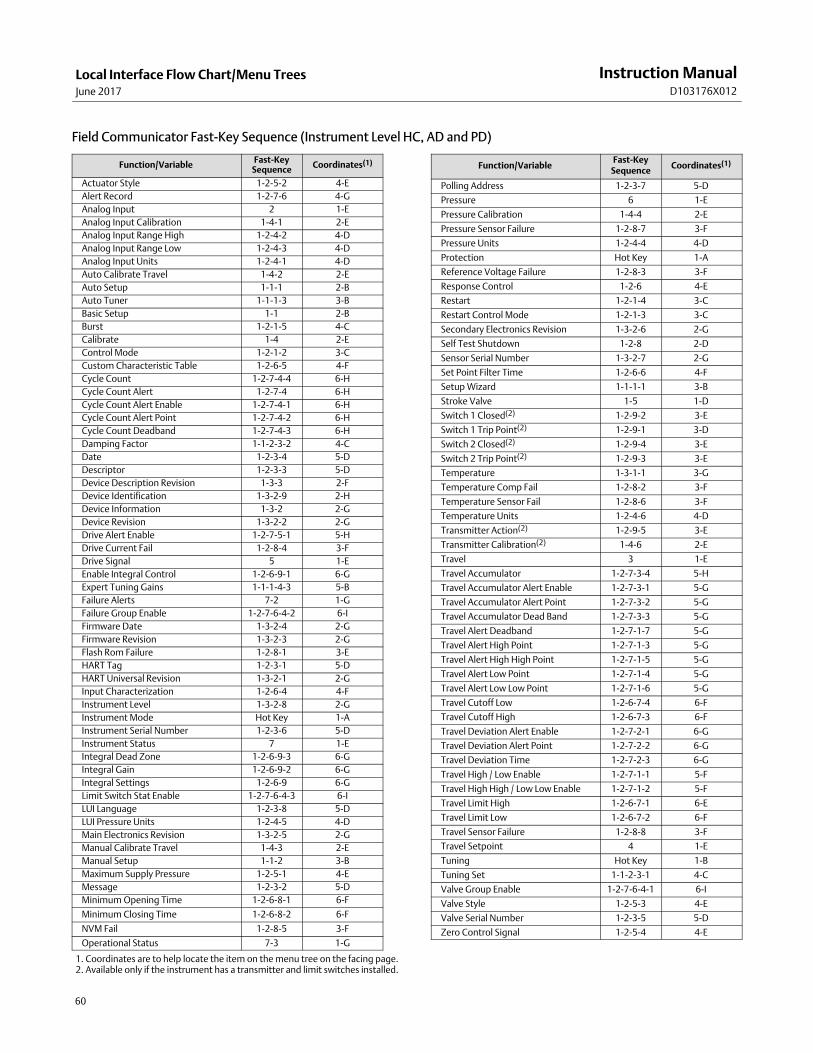
Local Interface Flow Chart/Menu TreesJune 2017
Instruction ManualD103176X012
60
Field Communicator Fast‐Key Sequence (Instrument Level HC, AD and PD)
Function/VariableFast-Key
SequenceCoordinates(1)
Actuator Style 1-2-5-2 4-E
Alert Record 1-2-7-6 4-G
Analog Input 2 1-E
Analog Input Calibration 1-4-1 2-E
Analog Input Range High 1-2-4-2 4-D
Analog Input Range Low 1-2-4-3 4-D
Analog Input Units 1-2-4-1 4-D
Auto Calibrate Travel 1-4-2 2-E
Auto Setup 1-1-1 2-B
Auto Tuner 1-1-1-3 3-B
Basic Setup 1-1 2-B
Burst 1-2-1-5 4-C
Calibrate 1-4 2-E
Control Mode 1-2-1-2 3-C
Custom Characteristic Table 1-2-6-5 4-F
Cycle Count 1-2-7-4-4 6-H
Cycle Count Alert 1-2-7-4 6-H
Cycle Count Alert Enable 1-2-7-4-1 6-H
Cycle Count Alert Point 1-2-7-4-2 6-H
Cycle Count Deadband 1-2-7-4-3 6-H
Damping Factor 1-1-2-3-2 4-C
Date 1-2-3-4 5-D
Descriptor 1-2-3-3 5-D
Device Description Revision 1-3-3 2-F
Device Identification 1-3-2-9 2-H
Device Information 1-3-2 2-G
Device Revision 1-3-2-2 2-G
Drive Alert Enable 1-2-7-5-1 5-H
Drive Current Fail 1-2-8-4 3-F
Drive Signal 5 1-E
Enable Integral Control 1-2-6-9-1 6-G
Expert Tuning Gains 1-1-1-4-3 5-B
Failure Alerts 7-2 1-G
Failure Group Enable 1-2-7-6-4-2 6-I
Firmware Date 1-3-2-4 2-G
Firmware Revision 1-3-2-3 2-G
Flash Rom Failure 1-2-8-1 3-E
HART Tag 1-2-3-1 5-D
HART Universal Revision 1-3-2-1 2-G
Input Characterization 1-2-6-4 4-F
Instrument Level 1-3-2-8 2-G
Instrument Mode Hot Key 1-A
Instrument Serial Number 1-2-3-6 5-D
Instrument Status 7 1-E
Integral Dead Zone 1-2-6-9-3 6-G
Integral Gain 1-2-6-9-2 6-G
Integral Settings 1-2-6-9 6-G
Limit Switch Stat Enable 1-2-7-6-4-3 6-I
LUI Language 1-2-3-8 5-D
LUI Pressure Units 1-2-4-5 4-D
Main Electronics Revision 1-3-2-5 2-G
Manual Calibrate Travel 1-4-3 2-E
Manual Setup 1-1-2 3-B
Maximum Supply Pressure 1-2-5-1 4-E
Message 1-2-3-2 5-D
Minimum Opening Time 1-2-6-8-1 6-F
Minimum Closing Time 1-2-6-8-2 6-F
NVM Fail 1-2-8-5 3-F
Operational Status 7-3 1-G
Function/VariableFast‐Key
SequenceCoordinates(1)
Polling Address 1-2-3-7 5-D
Pressure 6 1-E
Pressure Calibration 1-4-4 2-E
Pressure Sensor Failure 1-2-8-7 3-F
Pressure Units 1-2-4-4 4-D
Protection Hot Key 1-A
Reference Voltage Failure 1-2-8-3 3-F
Response Control 1-2-6 4-E
Restart 1-2-1-4 3-C
Restart Control Mode 1-2-1-3 3-C
Secondary Electronics Revision 1-3-2-6 2-G
Self Test Shutdown 1-2-8 2-D
Sensor Serial Number 1-3-2-7 2-G
Set Point Filter Time 1-2-6-6 4-F
Setup Wizard 1-1-1-1 3-B
Stroke Valve 1-5 1-D
Switch 1 Closed(2) 1-2-9-2 3-E
Switch 1 Trip Point(2) 1-2-9-1 3-D
Switch 2 Closed(2) 1-2-9-4 3-E
Switch 2 Trip Point(2) 1-2-9-3 3-E
Temperature 1-3-1-1 3-G
Temperature Comp Fail 1-2-8-2 3-F
Temperature Sensor Fail 1-2-8-6 3-F
Temperature Units 1-2-4-6 4-D
Transmitter Action(2) 1-2-9-5 3-E
Transmitter Calibration(2) 1-4-6 2-E
Travel 3 1-E
Travel Accumulator 1-2-7-3-4 5-H
Travel Accumulator Alert Enable 1-2-7-3-1 5-G
Travel Accumulator Alert Point 1-2-7-3-2 5-G
Travel Accumulator Dead Band 1-2-7-3-3 5-G
Travel Alert Deadband 1-2-7-1-7 5-G
Travel Alert High Point 1-2-7-1-3 5-G
Travel Alert High High Point 1-2-7-1-5 5-G
Travel Alert Low Point 1-2-7-1-4 5-G
Travel Alert Low Low Point 1-2-7-1-6 5-G
Travel Cutoff Low 1-2-6-7-4 6-F
Travel Cutoff High 1-2-6-7-3 6-F
Travel Deviation Alert Enable 1-2-7-2-1 6-G
Travel Deviation Alert Point 1-2-7-2-2 6-G
Travel Deviation Time 1-2-7-2-3 6-G
Travel High / Low Enable 1-2-7-1-1 5-F
Travel High High / Low Low Enable 1-2-7-1-2 5-F
Travel Limit High 1-2-6-7-1 6-E
Travel Limit Low 1-2-6-7-2 6-F
Travel Sensor Failure 1-2-8-8 3-F
Travel Setpoint 4 1-E
Tuning Hot Key 1-B
Tuning Set 1-1-2-3-1 4-C
Valve Group Enable 1-2-7-6-4-1 6-I
Valve Style 1-2-5-3 4-E
Valve Serial Number 1-2-3-5 5-D
Zero Control Signal 1-2-5-4 4-E
1. Coordinates are to help locate the item on the menu tree on the facing page.2. Available only if the instrument has a transmitter and limit switches installed.
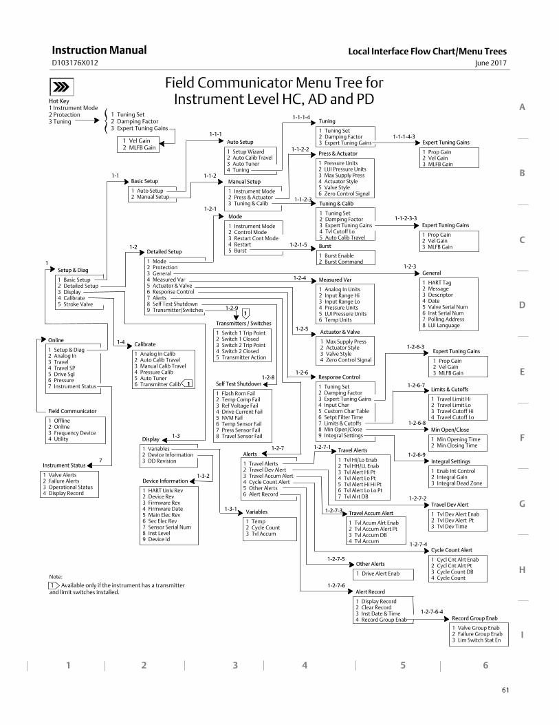
Local Interface Flow Chart/Menu TreesJune 2017
Instruction ManualD103176X012
61
Note:
1 Available only if the instrument has a transmitterand limit switches installed.
1 2 3 4 5 6
Online
1 Setup & Diag2 Analog In3 Travel4 Travel SP5 Drive Sgl6 Pressure7 Instrument Status
General
1 HART Tag2 Message3 Descriptor4 Date5 Valve Serial Num6 Inst Serial Num7 Polling Address8 LUI LanguageTransmitters / Switches
1 Switch 1 Trip Point2 Switch 1 Closed3 Switch 2 Trip Point4 Switch 2 Closed5 Transmitter Action
Auto Setup
1 Setup Wizard2 Auto Calib Travel3 Auto Tuner4 Tuning
Setup & Diag
1 Basic Setup2 Detailed Setup3 Display4 Calibrate5 Stroke Valve
Display
1 Variables2 Device Information3 DD Revision
Basic Setup
1 Auto Setup2 Manual Setup
Detailed Setup
1 Mode2 Protection3 General4 Measured Var5 Actuator & Valve6 Response Control7 Alerts8 Self Test Shutdown9 Transmitter/Switches
Field Communicator
1 Offline2 Online3 Frequency Device4 Utility
Manual Setup
1 Instrument Mode2 Press & Actuator3 Tuning & Calib
1‐1
1‐1‐1
1‐1‐2
Variables
1 Temp2 Cycle Count3 Tvl Accum
A
B
C
D
E
F
G
H
I
Press & Actuator
1 Pressure Units2 LUI Pressure Units3 Max Supply Press4 Actuator Style5 Valve Style6 Zero Control Signal
Tuning & Calib
1 Tuning Set2 Damping Factor3 Expert Tuning Gains4 Tvl Cutoff Lo5 Auto Calib Travel
1‐3
Device Information
1 HART Univ Rev2 Device Rev3 Firmware Rev4 Firmware Date5 Main Elec Rev6 Sec Elec Rev7 Sensor Serial Num8 Inst Level9 Device Id
Measured Var
1 Analog In Units2 Input Range Hi3 Input Range Lo4 Pressure Units5 LUI Pressure Units6 Temp Units
Field Communicator Menu Tree forInstrument Level HC, AD and PD
Tuning
1 Tuning Set2 Damping Factor3 Expert Tuning Gains Expert Tuning Gains
1 Prop Gain2 Vel Gain3 MLFB Gain
Expert Tuning Gains
1 Prop Gain2 Vel Gain3 MLFB Gain
Response Control
1 Tuning Set2 Damping Factor3 Expert Tuning Gains4 Input Char5 Custom Char Table6 Setpt Filter Time7 Limits & Cutoffs8 Min Open/Close9 Integral Settings
Integral Settings
1 Enab Int Control2 Integral Gain3 Integral Dead Zone
Calibrate
1 Analog In Calib2 Auto Calib Travel3 Manual Calib Travel4 Pressure Calib5 Auto Tuner6 Transmitter Calib
1
1
1‐1‐1‐4
1‐1‐1‐4‐3
1‐1‐2‐2
1‐1‐2‐3‐3
1
Mode
1 Instrument Mode2 Control Mode3 Restart Cont Mode4 Restart5 Burst
Burst
1 Burst Enable2 Burst Command
Actuator & Valve
1 Max Supply Press2 Actuator Style3 Valve Style4 Zero Control Signal
Expert Tuning Gains
1 Prop Gain2 Vel Gain3 MLFB Gain
Travel Accum Alert
1 Tvl Acum Alrt Enab2 Tvl Accum Alert Pt3 Tvl Accum DB4 Tvl Accum
Min Open/Close
1 Min Opening Time2 Min Closing Time
Alerts
1 Travel Alerts2 Travel Dev Alert3 Travel Accum Alert4 Cycle Count Alert5 Other Alerts6 Alert Record
Travel Alerts
1 Tvl Hi/Lo Enab2 Tvl HH/LL Enab3 Tvl Alert Hi Pt4 Tvl Alert Lo Pt5 Tvl Alert Hi Hi Pt6 Tvl Alert Lo Lo Pt7 Tvl Alrt DB
Travel Dev Alert
1 Tvl Dev Alert Enab2 Tvl Dev Alert Pt3 Tvl Dev Time
Cycle Count Alert
1 Cycl Cnt Alrt Enab2 Cycl Cnt Alrt Pt3 Cycle Count DB4 Cycle Count
Other Alerts
1 Drive Alert Enab
Alert Record
1 Display Record2 Clear Record3 Inst Date & Time4 Record Group Enab Record Group Enab
1 Valve Group Enab2 Failure Group Enab3 Lim Switch Stat En
Instrument Status
1 Valve Alerts2 Failure Alerts3 Operational Status4 Display Record
Self Test Shutdown
1 Flash Rom Fail2 Temp Comp Fail3 Ref Voltage Fail4 Drive Current Fail5 NVM Fail6 Temp Sensor Fail7 Press Sensor Fail8 Travel Sensor Fail
Limits & Cutoffs
1 Travel Limit Hi2 Travel Limit Lo3 Travel Cutoff Hi4 Travel Cutoff Lo
1‐1‐2‐3
1‐2‐1‐5
1‐2‐3
1‐2‐4
1‐2‐5
1‐2‐6
1‐2‐7
1‐2‐8
1‐2‐9
1‐2‐7‐1
1‐2‐7‐2
1‐2‐7‐3
1‐2‐7‐4
1‐2‐7‐5
1‐2‐7‐6
1‐2‐7‐6‐4
1‐2‐6‐3
1‐2‐6‐7
1‐2‐6‐8
1‐2‐6‐9
1‐2
1‐4
1‐3‐1
1‐3‐2
7
1‐2‐1
Hot Key1 Instrument Mode2 Protection3 Tuning
1 Vel Gain2 MLFB Gain
1 Tuning Set2 Damping Factor3 Expert Tuning Gains
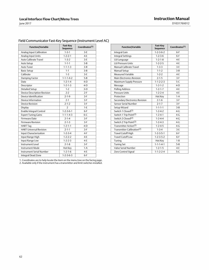
Local Interface Flow Chart/Menu TreesJune 2017
Instruction ManualD103176X012
62
Field Communicator Fast‐Key Sequence (Instrument Level AC)
Function/VariableFast‐Key
SequenceCoordinates(1)
Analog Input Calibration 1‐3‐1 3-E
Analog Input Units 1‐2‐2‐1 4-E
Auto Calibrate Travel 1‐3‐2 3-E
Auto Setup 1‐1‐1 3-B
Auto Tuner 1‐1‐1‐3 3-B
Basic Setup 1‐1 3-B
Calibrate 1‐3 3-E
Damping Factor 1‐1‐1‐4‐2 5-B
Date 1‐2‐1‐4 4-D
Descriptor 1‐2‐1‐3 4-D
Detailed Setup 1‐2 3-D
Device Description Revision 2‐2 2-F
Device Identification 2‐1‐9 3-F
Device Information 2‐1 3-F
Device Revision 2‐1‐2 3-F
Display 2 1-E
Enable Integral Control 1‐2‐3‐6‐1 6-F
Expert Tuning Gains 1‐1‐1‐4‐3 6-C
Firmware Date 2‐1‐4 3-F
Firmware Revision 2‐1‐3 3-F
HART Tag 1‐2‐1‐1 4-D
HART Universal Revision 2‐1‐1 3-F
Input Characterization 1‐2‐3‐4 4-F
Input Range High 1‐2‐2‐2 4-E
Input Range Low 1‐2‐2‐3 4-E
Instrument Level 2‐1‐8 3-F
Instrument Mode Hot Key 1-A
Instrument Serial Number 1‐2‐1‐6 4-E
Integral Dead Zone 1‐2‐3‐6‐3 6-F
Function/VariableFast‐Key
SequenceCoordinates(1)
Integral Gain 1‐2‐3‐6‐2 6-F
Integral Settings 1‐2‐3‐6 6-F
LUI Language 1‐2‐1‐8 4-E
LUI Pressure Units 1‐2‐2‐5 4-E
Manual Calibrate Travel 1‐3‐3 3-E
Manual Setup 1‐1‐2 3-B
Measured Variable 1‐2‐2 4-E
Main Electronics Revision 2‐1‐5 3-F
Maximum Supply Pressure 1‐1‐2‐2‐3 5-C
Message 1‐2‐1‐2 4-D
Polling Address 1‐2‐1‐7 4-E
Pressure Units 1‐2‐2‐4 4-E
Protection Hot Key 1-A
Secondary Electronics Revision 2‐1‐6 3-F
Sensor Serial Number 2‐1‐7 3-F
Setup Wizard 1‐1‐1‐1 3-B
Switch 1 Closed(2) 1‐2‐4‐2 4-G
Switch 1 Trip Point(2) 1‐2‐4‐1 4-G
Switch 2 Closed(2) 1‐2‐4‐4 4-G
Switch 2 Trip Point(2) 1‐2‐4‐3 4-G
Transmitter Action(2) 1‐2‐4‐5 4-G
Transmitter Calibration(2) 1‐3‐4 3-E
Travel Cutoff High 1‐2‐3‐5‐1 6-F
Travel Cutoff Low 1‐2‐3‐5‐2 6-F
Tuning Hot Key 1-B
Tuning Set 1‐1‐1‐4‐1 5-B
Valve Serial Number 1‐2‐1‐5 4-E
Zero Control Signal 1‐1‐2‐2‐4 5-C
1. Coordinates are to help locate the item on the menu tree on the facing page.2. Available only if the instrument has a transmitter and limit switches installed.
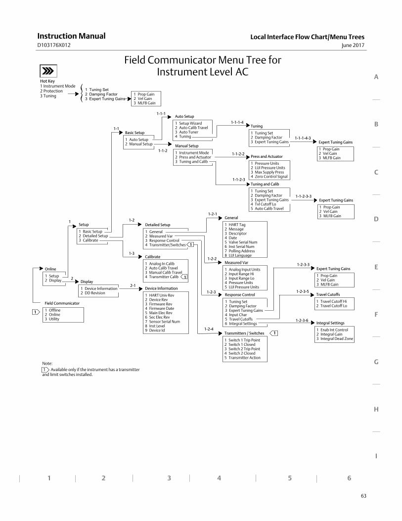
Local Interface Flow Chart/Menu TreesJune 2017
Instruction ManualD103176X012
63
Note:
1 Available only if the instrument has a transmitterand limit switches installed.
1 2 3 4 5
A
B
C
D
E
F
G
H
I
6
Online
1 Setup2 Display
General
1 HART Tag2 Message3 Descriptor4 Date5 Valve Serial Num6 Inst Serial Num7 Polling Address8 LUI Language
Transmitters / Switches
1 Switch 1 Trip Point2 Switch 1 Closed3 Switch 2 Trip Point4 Switch 2 Closed5 Transmitter Action
Auto Setup
1 Setup Wizard2 Auto Calib Travel3 Auto Tuner4 Tuning
Setup
1 Basic Setup2 Detailed Setup3 Calibrate
Display
1 Device Information2 DD Revision
Basic Setup
1 Auto Setup2 Manual Setup
Detailed Setup
1 General2 Measured Var3 Response Control4 Transmitter/Switches
Field Communicator
1 Offline2 Online3 Utility
Manual Setup
1 Instrument Mode2 Press and Actuator3 Tuning and Calib
1‐1
1‐1‐1
1‐1‐2
1
Travel Cutoffs
1 Travel Cutoff Hi2 Travel Cutoff Lo
Press and Actuator
1 Pressure Units2 LUI Pressure Units3 Max Supply Press4 Zero Control Signal
Tuning and Calib
1 Tuning Set2 Damping Factor3 Expert Tuning Gains4 Tvl Cutoff Lo5 Auto Calib Travel
1‐1‐2‐3
Device Information
1 HART Univ Rev2 Device Rev3 Firmware Rev4 Firmware Date5 Main Elec Rev6 Sec Elec Rev7 Sensor Serial Num8 Inst Level9 Device Id
2
1
Measured Var
1 Analog Input Units2 Input Range Hi3 Input Range Lo4 Pressure Units5 LUI Pressure Units
Field Communicator Menu Tree forInstrument Level AC
Tuning
1 Tuning Set2 Damping Factor3 Expert Tuning Gains Expert Tuning Gains
1 Prop Gain2 Vel Gain3 MLFB Gain
Expert Tuning Gains
1 Prop Gain2 Vel Gain3 MLFB Gain
Response Control
1 Tuning Set2 Damping Factor3 Expert Tuning Gains4 Input Char5 Travel Cutoffs6 Integral Settings Integral Settings
1 Enab Int Control2 Integral Gain3 Integral Dead Zone
Calibrate
1 Analog In Calib2 Auto Calib Travel3 Manual Calib Travel4 Transmitter Calib
1
1‐1‐1‐4
1‐1‐1‐4‐3
1‐1‐2‐2
1‐1‐2‐3‐3
1‐2
1‐2‐1
1‐2‐2
1‐2‐3‐5
1‐2‐4
1‐3
2‐1
1‐2‐3
1
Hot Key1 Instrument Mode2 Protection3 Tuning 1 Prop Gain
2 Vel Gain3 MLFB Gain
Expert Tuning Gains
1 Prop Gain2 Vel Gain3 MLFB Gain
1‐2‐3‐3
1‐2‐3‐6
1
1 Tuning Set2 Damping Factor3 Expert Tuning Gains

Local Interface Flow Chart/Menu TreesJune 2017
Instruction ManualD103176X012
64
GlossaryJune 2017
Instruction ManualD103176X012
65
Glossary
Alert PointAn adjustable value that, when exceeded,activates an alert.
AlgorithmA set of logical steps to solve a problem oraccomplish a task. A computer program containsone or more algorithms.
AlphanumericConsisting of letters and numbers.
Analog Input UnitsUnits in which the analog input is displayed andmaintained in the instrument.
ANSI (acronym)The acronym ANSI stands for the AmericanNational Standards Institute
ANSI ClassValve pressure/temperature rating.
Bench SetPressure, supplied to an actuator, required todrive the actuator through rated valve travel.Expressed in pounds per square inch.
ByteA unit of binary digits (bits). A byte consists ofeight bits.
Calibration LocationWhere the instrument was last calibrated; eitherin the factory or in the field.
ConfigurationStored instructions and operating parameters fora FIELDVUE Instrument.
Control LoopAn arrangement of physical and electroniccomponents for process control. The electroniccomponents of the loop continuously measureone or more aspects of the process, then alterthose aspects as necessary to achieve a desiredprocess condition. A simple control loopmeasures only one variable. More sophisticatedcontrol loops measure many variables andmaintain specified relationships among thosevariables.
Control ModeDefines where the instrument reads its set point.The following control modes are available for aFIELDVUE instrument:Analog The instrument receives its travel setpoint over the 4-20 mA loop. Digital The instrument receives its set pointdigitally, via the HART communications link.Test This is not a user‐selectable mode. The FieldCommunicator or ValveLink Software places theinstrument in this mode whenever it needs tomove the valve, such as for calibration ordiagnostic tests.
Control Mode, RestartDetermines the instrument control mode after arestart. See Control Mode for the available restartcontrol modes.
GlossaryJune 2017
Instruction ManualD103176X012
66
ControllerA device that operates automatically to regulate acontrolled variable.
Current‐to‐Pressure (I/P) ConverterAn electronic component or device that convertsa milliamp signal to a proportional pneumaticpressure output signal.
Cycle CounterThe capability of a FIELDVUE instrument to recordthe number of times the travel changes direction.The change in direction must occur after thedeadband has been exceeded before it can becounted as a cycle.
Cycle Counter AlertChecks the difference between the Cycle Counterand the Cycle Counter Alert Point. Cycle CounterAlert is active when the cycle counter valueexceeds the Cycle Counter Alert Point. It clearsafter you reset the Cycle Counter to a value lessthan the alert point.
Cycle Counter Alert PointAn adjustable value which, when exceeded,activates the Cycle Counter Alert. Valid entriesare 0 to 4 billion cycles.
Cycle Counter DeadbandRegion around the travel reference point, inpercent of ranged travel, established at the lastincrement of the Cycle Counter. The deadbandmust be exceeded before a change in travel canbe counted as a cycle. Valid entries are 0% to100%. Typical value is between 2% and 5%.
DeviationUsually, the difference between set point andprocess variable. More generally, any departurefrom a desired or expected value or pattern.
Device IDUnique identifier embedded in the instrument atthe factory.
Device RevisionRevision number of the interface software thatpermits communication between the FieldCommunicator and the instrument.
Drive SignalThe signal to the I/P converter from the printedwiring board. It is the percentage of the totalmicroprocessor effort needed to drive the valvefully open.
Drive Signal AlertChecks the drive signal and calibrated travel. Ifone of the following conditions exists for morethan 20 seconds, the Drive Signal Alert is active. Ifnone of the conditions exist, the alert is cleared.If Zero Control Signal = Closed
The alert is active when:
drive signal <10% and calibrated travel >3%
drive signal >90% and calibrated travel <97%
If Zero Control Signal = Open
The alert is active when:
drive signal <10% and calibrated travel <97%
drive signal >90% and calibrated travel >3%
GlossaryJune 2017
Instruction ManualD103176X012
67
Equal PercentageA valve flow characteristic where equalincrements of valve stem travel produce equalpercentage changes in existing flow. One of theinput characteristics available for a FIELDVUEInstrument. See also, Linear and Quick Opening.
Feedback SignalIndicates to the instrument the actual position ofthe valve. The travel sensor provides the feedbacksignal to the instrument printed wiring boardassembly.
Firmware RevisionThe revision number of the instrument firmware.Firmware is a program that is entered into theinstrument at time of manufacture and cannot bechanged by the user.
Free TimePercent of time that the microprocessor is idle. Atypical value is 25%. The actual value depends onthe number of functions in the instrument thatare enabled and on the amount ofcommunication currently in progress.
Full Ranged TravelCurrent, in mA, that corresponds with the pointwhere ranged travel is maximum, i.e., limited bythe mechanical travel stops.
GainThe ratio of output change to input change.
Hardware RevisionRevision number of the Fisher instrumenthardware. The physical components of theinstrument are defined as the hardware.
HART (acronym)The acronym HART stands for HighwayAddressable Remote Transducer.
HART TagAn eight‐character name that identifies thephysical instrument.
HART Universal RevisionRevision number of the HART UniversalCommands which are the communicationsprotocol for the instrument.
Input CharacteristicThe relationship between the ranged travel andranged input. Possible values include: linear,equal percentage, and quick opening.
Input CurrentThe current signal from the control system thatserves as the analog input to the instrument. Seealso Input Signal.
Input RangeThe analog input signal range that corresponds tothe travel range.
Input SignalThe current signal from the control system. Theinput signal can be displayed in milliamperes or inpercent of ranged input.
Instrument LevelDetermines the functions available for theinstrument. See table 3‐1.
Instrument ModeDetermines if the instrument responds to itsanalog input signal. There are two instrumentmodes:In Service: For a fully functioning instrument, theinstrument output changes in response to analoginput changes. Typically changes to setup orcalibration cannot be made when the instrumentmode is In Service.Out of Service: The instrument output does notchange in response to analog input changeswhen the instrument mode is Out of Service.Some setup parameters can be changed onlywhen the instrument mode is Out of Service.
GlossaryJune 2017
Instruction ManualD103176X012
68
Instrument ProtectionDetermines if commands from a HART device cancalibrate and/or configure certain parameters inthe instrument. There are two types ofinstrument protection:Configuration and Calibration: Prohibits changingprotected setup parameters; prohibitscalibration.None: Permits both configuration and calibration.The instrument is ”unprotected.”
Instrument Serial NumberThe serial number assigned to the printed wiringboard by the factory but can be changed duringsetup. The instrument serial number shouldmatch the serial number on the instrumentnameplate.
Leak ClassDefines the allowable leakage by a valve when it isclosed. Leak class numbers are listed in twostandards: ANSI/FCI 70‐2‐1991 and IEC 534‐4.
LinearA valve flow characteristic where changes in flowrate are directly proportional to changes in valvestem travel. One of the input characteristicsavailable for a FIELDVUE Instrument. See also,Equal Percentage and Quick Opening.
Linearity, dynamicLinearity (independent) is the maximumdeviation from a straight line best fit to theopening and closing curves and a linerepresenting the average value of those curves.
MemoryA type of semiconductor used for storingprograms or data. FIELDVUE instruments usethree types of memory: Random Access Memory(RAM), Read Only Memory (ROM), andNon‐Volatile Memory (NVM). See also theselistings in this glossary.
MenuA list of programs, commands, or other activitiesthat you select by using the arrow keys tohighlight the item then pressing ENTER, or byentering the numeric value of the menu item.
Minimum Closing TimeMinimum time, in seconds, for the travel todecrease through the entire ranged travel. Thisrate is applied to any travel decrease. Valid entriesare 0 to 400 seconds. Deactivate by entering avalue of 0 seconds.
Minimum Opening TimeMinimum time, in seconds, for the travel toincrease through the entire ranged travel. Thisrate is applied to any travel increase. Because offriction, actual valve travel may not respond inexactly the same time frame. Valid entries are 0to 400 seconds. Deactivate by entering a value of0 seconds.
Non‐Volatile Memory (NVM)A type of semiconductor memory that retains itscontents even though power is disconnected.NVM contents can be changed duringconfiguration unlike ROM which can be changedonly at time of instrument manufacture. NVMstores configuration restart data.
ParallelSimultaneous: said of data transmission on two ormore channels at the same time.
Polling AddressAddress of the instrument. If the digital valvecontroller is used in a point‐to‐pointconfiguration, set the polling address to 0. If it isused in a multidrop configuration, or split rangeapplication, set the polling address to a valuefrom 0 to 15.
GlossaryJune 2017
Instruction ManualD103176X012
69
Pressure SensorA FIELDVUE instrument internal device thatsenses pneumatic pressure. DVC2000 digitalvalve controllers have one actuator pressuresensor.
Primary MasterMasters are communicating devices. A primarymaster is a communicating device permanentlywired to a field instrument. Typically, aHART‐compatible control system or a computerrunning ValveLink Software is the primary master.
In contrast, a secondary master is not oftenpermanently wired to a field instrument. The 375Field Communicator or a computer runningValveLink Software communicating through aHART modem could be considered a secondarymaster.
Note: If one type of master takes an instrumentOut Of Service, the same type must put it InService. For example, if a device set up as aprimary master takes an instrument Out OfService, a device set up as a primary master mustbe used to place the instrument In Service.
Quick OpeningA valve flow characteristic where most of thechange in flow rate takes place for small amountsof stem travel from the closed position. The flowcharacteristic curve is basically linear through thefirst 40 percent of stem travel. One of the inputcharacteristics available for a FIELDVUEInstrument. See also, Equal Percentage andLinear.
Random Access Memory (RAM)A type of semiconductor memory that is normallyused by the microprocessor during normaloperation that permits rapid retrieval and storageof programs and data. See also Read OnlyMemory (ROM) and Non‐Volatile Memory (NVM).
RateAmount of change in output proportional to therate of change in input.
Read‐Only Memory (ROM)A memory in which information is stored at thetime of instrument manufacture. You canexamine but not change ROM contents.
Seat LoadForce exerted on the valve seat, typicallyexpressed in pounds force per lineal inch of portcircumference. Seat load is determined by shutoffrequirements.
Set Point Filter TimeThe time constant, in seconds, for the first‐orderinput filter.
SoftwareMicroprocessor or computer programs androutines that reside in alterable memory (usuallyRAM), as opposed to firmware, which consists ofprograms and routines that are programmed intomemory (usually ROM) when the instrument ismanufactured. Software can be manipulatedduring normal operation, firmware cannot.
Stroking TimeThe time, in seconds, required to move the valvefrom its fully open position to fully closed, or viceversa.
Temperature SensorA device within the FIELDVUE instrument thatmeasures the instrument's internal temperature.
TravelMovement of the valve stem or shaft whichchanges the amount the valve is open or closed.
Travel AccumulatorThe capability of a FIELDVUE instrument to recordtotal change in travel. The value of the TravelAccumulator increments when the magnitude ofthe change exceeds the Travel AccumulatorDeadband. To reset the Travel Accumulator, set itto zero.
GlossaryJune 2017
Instruction ManualD103176X012
70
Travel Accumulator AlertChecks the difference between the TravelAccumulator value and the Travel AccumulatorAlert Point. The Travel Accumulator Alert is activewhen the Travel Accumulator value exceeds theTravel Accumulator Alert Point. It clears after youreset the Travel Accumulator to a value less thanthe alert point.
Travel Accumulator Alert PointAn adjustable value which, when exceeded,activates the Travel Accumulator Alert. Validentries are 0% to 4 billion %.
Travel Accumulator DeadbandRegion around the travel reference pointestablished at the last increment of theaccumulator. This region must be exceededbefore a change in travel can be accumulated.Valid entries are 0% to 100%.
Travel AlertChecks the ranged travel against the travel highand low alert points. The travel alert is active ifeither the high or low point is exceeded. Once ahigh or low point is exceeded, the ranged travelmust clear that point by the Travel AlertDeadband before the alert clears. Four travelalerts are available: Travel Alert Hi, Travel Alert Lo,Travel Alert Hi Hi, and Travel Alert Lo Lo.
Travel Alert DeadbandTravel, in percent of ranged travel, required toclear a travel alert, once it is active. Valid entriesare -25% to 125%.
Travel Alert High PointValue of the travel, in percent of ranged travel,which, when exceeded, sets the Travel Alert Hialert. Valid entries are -25% to 125%.
Travel Alert High High PointValue of the travel, in percent of ranged travel,which, when exceeded, sets the Travel Alert Hi Hialert. Valid entries are -25% to 125%.
Travel Alert Low PointValue of the travel, in percent of ranged travel,which, when exceeded, sets the Travel Alert Loalert. Valid entries are -25% to 125%.
Travel Alert Low Low PointValue of the travel, in percent of ranged travel,which, when exceeded, sets the Travel Alert Lo Loalert. Valid entries are -25% to 125%.
Travel CutoffDefines the cutoff point for the travel, in percentof ranged travel. There are two travel cutoffs:high and low. Once travel exceeds the cutoff, thedrive signal is set to either maximum orminimum, depending on the Zero Control Signaland if the cutoff is high or low. Minimum openingtime or minimum closing time are not in effectwhile the travel is beyond the cutoff. Use thetravel cutoff to obtain the desired seat load or tobe sure the valve is fully open.
Travel DeviationThe difference between the analog input signal(in percent of ranged input), the “target” travel,and the actual “ranged” travel.
Travel Deviation AlertChecks the difference between the target and theranged travel. If the difference exceeds the TravelDeviation Alert Point for more than the TravelDeviation Time, the Travel Deviation Alert isactive. It remains active until the difference is lessthan the Travel Deviation Alert Point.
Travel Deviation Alert PointAn adjustable value for the target travel and theranged travel difference, expressed in percent,When this value is exceeded by the traveldeviation for more than the Travel DeviationTime, the Travel Deviation Alert is active. Validentries are 0% to 100%. Typically this is set to 5%.
Travel Deviation TimeThe time, in seconds. that the travel deviationmust exceed the Travel Deviation Alert Pointbefore the alert is active. Valid entries are 1 to 60seconds.
GlossaryJune 2017
Instruction ManualD103176X012
71
Travel LimitA setup parameter that defines the maximumallowable travel (in percent of ranged travel) forthe valve. During operation, the travel target willnot exceed this limit. There are two travel limits:high and low. Typically the travel limit low will beused to keep the valve from going completelyclosed.
Travel RangeTravel, in percent of calibrated travel, thatcorresponds to the input range.
Travel SensorA device within the FIELDVUE instrument thatsenses valve stem or shaft movement.
TuningThe adjustment of control terms or parametervalues to produce a desired control effect.
Tuning SetPreset values that identify gain settings for aFIELDVUE instrument. The tuning set and supplypressure together determine an instrument'sresponse to input signal changes.
Watch Dog TimerA timer that the microprocessor must rearmperiodically. If the microprocessor is unable torearm the timer, the instrument goes throughreset.
Zero Control SignalA setup parameter that determines whether thevalve is fully open or fully closed when the inputsignal is 0%.

GlossaryJune 2017
Instruction ManualD103176X012
72
IndexJune 2017
Instruction ManualD103176X012
73
Index
AAC (Auto Calibrate), 4, 34
Actuator and Valve Information, 16
Actuator Information, for Setup, 12
AD (Advanced Diagnostics), 4, 34
Advanced Diagnostics (AD), 4, 34
Air Capacity, 5
Air Consumption, 5
Airset option, 6
Alert Record, 23, 36Clearing, 23Displaying, 23Enabling Alert Groups, 23Inst Date & Time, 23
Alert Record has Entries, 35
Alert Record is full, 35
Alerts, 19Alert Record, 36Enabling
Cycle Counter, 22Drive Signal, 23Travel Accumulator, 21Travel Alerts
High and Low, 20High High and Low Low, 20
Travel Deviation, 21Setting, 19
Cycle Counter, 22Other Alerts, 23Travel Alerts, 20
High, High-High, Low and Low-Low, 20Travel Accumulation, 21Travel Deviation, 21
Valve Alerts, 35
Analog Calibration Adjust, 29
Analog InputCalibration, 27Display Value, 33Range Hi, 15Range Lo, 15
Analog Input , Calibrationusing the Field Communicator, 27via Local Interface, 28
Analog Input Signal, 5
Analog Input Units, 15
ATEX, Hazardous Area Classification, 5
Auto Calibrate (AC), 4, 34
Auto Calibrate Travel, 28
auto tuner, 26
BBasic Setup and Calibration, using the Local Operator
Interface, 3
Burst Mode, 10Commands, 10Enabling, 10
CCalibration
Analog Input, 27using the Field Communicator, 27via Local Interface, 28
Auto Calibrate Travel, 28Manual Calibrate Travel, 29Output Pressure Sensor, 30Position Transmitter, 31Pressure Sensor, 30
CertificationsCUTR, Russia, Kazakhstan, Belarus, and Armenia, 6INMETRO, Brazil, 6KGS, South Korea, 6NEPSI, China, 6PESO CCOE, India, 6
Clear Record, 23
Command 3, 10
Component Replacement, 41
Config & Calib, 12
ConnectionsElectrical, 3Pneumatic, 3specifications, 6
Control Mode, 9
CSA, Hazardous Area Classification, 5
Customs Union Technical Regulations (CUTR), Russia,Kazakhstan, Belarus, and Armenia, Certification, 6
IndexJune 2017
Instruction ManualD103176X012
74
Cycle CounterDisplaying Value, 33Enabling Alert, 22Resetting, 23
Cycle Counter Alert, 22, 35
Cycle Counter Alert Enable, 22
Cycle Counter Alert Point, 22
Cycle Counter Deadband, 22
DDamping Factor, Tuning, 17
Date, 14
Declaration of SEP, 6
Descriptor, 14
Detailed Setup, 9
Detailed Setup Parameters, Factory Default, 11
Device ID, 34
Device Information, 34
Device Revision, 34
Digital Calibration Adjust, 29
Display Record, 23
Drive Alert Enable, 23
Drive Current Failure, 24, 36
Drive Signal, 23, 55Displaying Value, 33Enabling Alert, 23
Drive Signal Alert, 35
EEducational Services, 8
Electrical Classification, 5Electrical Housing, 6Hazardous Area, 5
Electrical Connections, 3
Electrical Housing Classification, 6
Electromagnetic Compatibility, 5
EMC Summary Results, Immunity, 7
Expert Tuning, Gains, 17
FFactory Default Settings, Detailed Setup Parameters,
11
Failure Alerts, 36Drive Current Fail, 36Flash ROM Fail, 36NVM Fail, 36Offline/Failed, 36Pressure Sensor Fail, 36Ref Voltage Fail, 36Temperature Sensor Fail, 36Travel Sensor Fail, 36
Fast Key Sequences, Field Communicator, 57
Firmware Date, 34
Firmware Revision, 34
Flash ROM Failure, 24, 36
FM, Hazardous Area Classification, 5
GGeneral Information, 14
HHART Communicating (HC), 4, 34
HART Tag, 14
HART Universal Revision, 34
Hazardous Area ClassificationsATEX, 5CSA, 5FM, 5IECEx, 5
HC (HART Communicating), 4, 34
II/P Converter
Assembly, 43Removal, 42Replacing, 41
IEC 60534-6-1 mounting standards, 5
IEC 60534-6-2 mounting standards, 5
IEC 61326-1 (First Edition), 5
IECEx, Hazardous Area Classification, 5
Independent Linearity, 5
IndexJune 2017
Instruction ManualD103176X012
75
INMETRO, Brazil, Certification, 6
Input Characteristic, 17
Input Impedance, 5
Input Range High, 15
Input Range Low, 15
Input Signal, 5, 55Analog Input Signal, 5Maximum Voltage, 5Minimum Control Current, 5Minimum Voltage, 5Overcurrent Protection, 5Reverse Polarity Protection, 5
Inst Date & Time, Alert Record, 23
Installation, 3
Instrument Clock, Setting, 23
Instrument Level, 4, 34
Instrument Mode, 9
Instrument Removal, 40
Instrument Replacement, 40
Instrument Serial Number, 14
Instrument Status, 35
Instrument Time is Invalid, 35
Integral Dead Zone, 19
Integral Enable, 19
Integral Gain, 19
Internal Temperature Sensor, Self Test Failure, 24
ISA Standard 7.0.01, 5
ISO 8573-1, 5
KKGS, South Korea, Certification, 6
LLimit Switches, 6
OFF State, 6ON State, 6Supply Voltage, 6
Local Interface, 4
Local Interface Flow Chart, 58
LUI Language, 14
LUI Pressure Units, 15
MMagnet Assembly, 4
Magnetic Feedback Assembly, Replacing, 41
Main Electronics Revision, 34
Manual Calibrate Travel, 29
Materials of Construction, DVC2000, 6
Maximum Supply Pressure, 16
Maximum Voltage, 5
Message, 14
Minimum Closing Time, 19
Minimum Control Current, 5
Minimum Opening Time, 19
Minimum Voltage, 5
ModeBurst, 10Control, 9Instrument, 9
Mounting, Specifications, 6
NNAMUR mounting standards, 5
NEPSI, China, Certification, 6
Non-critical NVM Alert, 35
NVM Failure, 24, 36
OOffline/Failed, 36
Operational Status, 37
Options, 6
Options Board, 4
Output Pressure Sensor, Calibration, 30
Output Signal, 5Action, 5Maximum Span, 5Minimum Span, 5
Overcurrent Protection, 5
IndexJune 2017
Instruction ManualD103176X012
76
PParameters
conditions for modifying, 13Factory Default, 11
PartsKits, 49Ordering, 49
PD (Performance Diagnostics), 4, 34
PED Directive 2014/38/EU, 6
Performance Diagnostics (PD), 4, 34
PESO CCOE, India, Certification, 6
Pipe-away vent option, 6
Pneumatic Connections, 3
pneumatic output signal, 56
Pneumatic Relay, 43Assembly, 43Removal, 43Replacing, 43
Pole Piece, 4
Polling Address, 14
Position Transmitter Calibration, 31
Power Starvation Alert, 35
Pressure, Instrument Output, Value, 33
Pressure Sensor Calibration, 30
Pressure Sensor Failure, 24, 36
pressure signal, 56
Pressure Units, 15
Principle of Operation, 55drive signal, 55input signal, 55pneumatic output signal, 56pressure signal, 56
Protection, 12
RRecord Group Enab, 23
Ref Voltage Failure, 36
Limit, Reference Accuracy, 6
Reference Voltage Failure, 24
Related Documents, 7
relay pressure range, 44
Restart Control Mode, 10
Restarting the Instrument, 10
Reverse Polarity Protection, 5
Revision InformationDevice, 34Firmware, 34HART Universal, 34Main Electronics, 34Secondary Electronics, 34
SSecondary Electronics Revision, 34
Self Test Failures for Instrument Shutdown, 24
Sensor Serial Number, 34
Serial NumberInstrument, 14Sensor, 34Valve, 14
Setpoint Filter Time, 18
Setting Response, 16
Shaft Rotation, 6
Specifications, 5
Stem Travel, 6
Stroke Valve, 39
Supply Pressure, 5Maximum, 16
Switch #1Closed, 25Trip Point, 25
Switch #2Closed, 25Trip Point, 25
Switches, 25
TTemperature, Internal, Displaying Value, 33
Temperature Compensation Failure, 24
Temperature Limits, 5
Temperature Sensor Failure, 24, 36
Temperature Units, 15
IndexJune 2017
Instruction ManualD103176X012
77
Transmitter, 6, 25Fault Indication, 6Reference Accuracy, 6Supply Voltage, 6
Transmitter Action, 25
Transmitter/Switches, 25
Travel, 33Displaying Value, 33
Travel AccumulatorDisplaying Value, 34Enabling Alert, 21Resetting, 21
Travel Accumulator Alert Point, 21
Travel Accumulator Deadband, 21
Travel Alert Deadband, 21
Travel Alert High Point, 20
Travel Alert Low Point, 20
Travel Alerts, 20High and Low, 20High High and Low Low, 20
Travel CutoffsHigh, 19Low, 19
Travel Deviation Alert, 21
Travel LimitsHigh, 18Low, 19
Travel Sensor Failure, 24, 36
Troubleshooting, 44What are the observable symptoms?, 44What is a healthy unit, 44
TuningAutomatic, 26Damping Factor, 17Integral Enable, 19Manual, 26Tuning Set, 16
Tuning Set, 16
Tvl Accumulation Alert, 35
Tvl Alert Hi, 35
Tvl Alert Hi Hi, 35
Tvl Alert Lo, 35
Tvl Alert Lo Lo, 35
Tvl Deviation Alrt, 35
Tvl Lim/Cutoff High, 35
Tvl Lim/Cutoff Low, 35
V
Valve Alerts, 35Alert Record has Entries, 35Alert Record is Full, 35Cycle Counter Alert, 35Drive Signal Alert, 35Instrument Time is Invalid, 35Non-critical NVM Alert, 35Power Starvation Alert, 35Tvl Accumulation Alert, 35Tvl Alert Hi, 35Tvl Alert Hi Hi, 35Tvl Alert Lo, 35Tvl Alert Lo Lo, 35Tvl Deviation Alrt, 35Tvl Lim/Cutoff High, 35Tvl Lim/Cutoff Low, 35
Valve Serial Number, 14
Valve Setpoint, Displaying Value, 33
VDI/VDE 3845 mounting standards, 5
Vibration Testing Method, 5
Viewing Variables, 33Analog Input, Travel, Valve Set Point, Drive Signal
and Output Pressure, 33
Voltage Available, Checking, 46
W
Weight, DVC2000, 6
Z
Zero Control Signal, 15, 16, 23, 71

IndexJune 2017
Instruction ManualD103176X012
78

Digital Valve ControllerJune 2017
Instruction ManualD103176X012
79
DVC2000 Digital Valve ControllerJune 2017
Instruction ManualD103176X012
80
Emerson Automation SolutionsMarshalltown, Iowa 50158 USASorocaba, 18087 BrazilCernay, 68700 FranceDubai, United Arab EmiratesSingapore 128461 Singapore
www.Fisher.com
The contents of this publication are presented for informational purposes only, and while every effort has been made to ensure their accuracy, they are notto be construed as warranties or guarantees, express or implied, regarding the products or services described herein or their use or applicability. All sales aregoverned by our terms and conditions, which are available upon request. We reserve the right to modify or improve the designs or specifications of suchproducts at any time without notice.
� 2004, 2017 Fisher Controls International LLC. All rights reserved.
Fisher, FIELDVUE, ValveLink, Tri-Loop, Rosemount are marks owned by one of the companies in the Emerson Automation Solutions business unit of EmersonElectric Co. Emerson Automation Solutions, Emerson, and the Emerson logo are trademarks and service marks of Emerson Electric Co. HART is a registeredtrademark of FieldComm Group. All other marks are the property of their respective owners.
Neither Emerson, Emerson Automation Solutions, nor any of their affiliated entities assumes responsibility for the selection, use or maintenanceof any product. Responsibility for proper selection, use, and maintenance of any product remains solely with the purchaser and end user.