fisher fieldvue™ dvc6000 sis digital valve controllers … … · fisher fieldvue™ dvc6000 sis...
TRANSCRIPT
Fisher� FIELDVUE™ DVC6000 SIS Digital ValveControllers for Safety Instrumented System (SIS)Solutions Instruction Manual(Supported)
Supported products may not be manufactured again in any Emerson Process Management location under anyconditions. Spare parts availability is 7 years of best effort. Technical support is available.
Post‐sale documents (such as instruction manuals and quick start guides) are available on the CD and FishWeb. Manyare also available at www.fisher.com.
Instruction manuals for supported products may be updated, if required, to support products in the field.
Pre‐sale documents (such as bulletins) for supported products are included on FishWeb for internal use. They are notincluded on the CD.
Supported ProductD103230X012
DVC6000 SIS Digital Valve ControllersOctober 2013
Emerson Process Management Marshalltown, Iowa 50158 USASorocaba, 18087 BrazilChatham, Kent ME4 4QZ UKDubai, United Arab EmiratesSingapore 128461 Singapore
www.Fisher.com
The contents of this publication are presented for informational purposes only, and while every effort has been made to ensure their accuracy, they are notto be construed as warranties or guarantees, express or implied, regarding the products or services described herein or their use or applicability. All sales aregoverned by our terms and conditions, which are available upon request. We reserve the right to modify or improve the designs or specifications of suchproducts at any time without notice.
� 2013 Fisher Controls International LLC. All rights reserved.
Fisher and FIELDVUE are marks owned by one of the companies in the Emerson Process Management business unit of Emerson Electric Co. Emerson ProcessManagement, Emerson, and the Emerson logo are trademarks and service marks of Emerson Electric Co. All other marks are the property of their respectiveowners.
Neither Emerson, Emerson Process Management, nor any of their affiliated entities assumes responsibility for the selection, use or maintenanceof any product. Responsibility for proper selection, use, and maintenance of any product remains solely with the purchaser and end user.

Introduction and Specifications
Installation
Basic Setup
Detailed Setup
Calibration
Viewing Device Variables and Diagnostics
Maintenance and Troubleshooting
Parts
Appendices
Principle of Operation
Loop Schematics/Nameplates
Glossary
Index
DVC6000 SISInstruction Manual
D103230X012September 2013
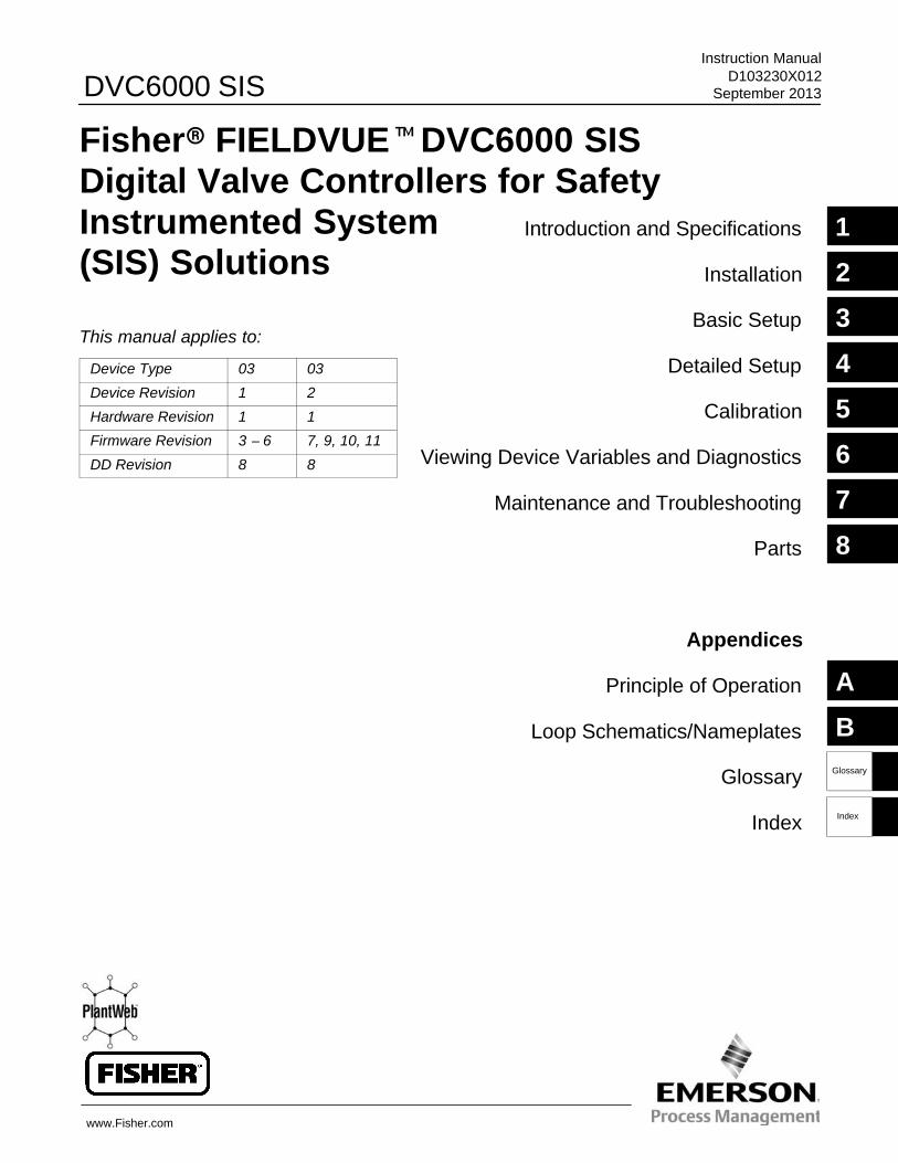
Fisher� FIELDVUE�DVC6000 SISDigital Valve Controllers for SafetyInstrumented System(SIS) Solutions
This manual applies to:
Device Type 03 03
Device Revision 1 2
Hardware Revision 1 1
Firmware Revision 3 − 6 7, 9, 10, 11
DD Revision 8 8
www.Fisher.com
1
2
3
4
5
6
7
8
A
BGlossary
14Index
DVC6000 SIS
ii
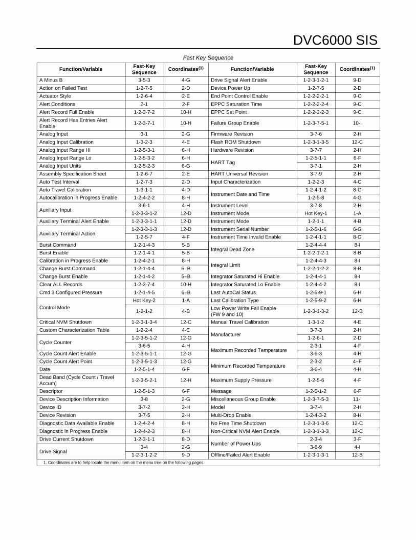
Fast Key Sequence
Function/Variable Fast-KeySequence
Coordinates(1) Function/Variable Fast-KeySequence
Coordinates(1)
A Minus B 3-5-3 4-G Drive Signal Alert Enable 1-2-3-1-2-1 9-D
Action on Failed Test 1-2-7-5 2-D Device Power Up 1-2-7-5 2-D
Actuator Style 1-2-6-4 2-E End Point Control Enable 1-2-2-2-2-1 9-C
Alert Conditions 2-1 2-F EPPC Saturation Time 1-2-2-2-2-4 9-C
Alert Record Full Enable 1-2-3-7-2 10-H EPPC Set Point 1-2-2-2-2-3 9-C
Alert Record Has Entries AlertEnable
1-2-3-7-1 10-H Failure Group Enable 1-2-3-7-5-1 10-I
Analog Input 3-1 2-G Firmware Revision 3-7-6 2-H
Analog Input Calibration 1-3-2-3 4-E Flash ROM Shutdown 1-2-3-1-3-5 12-C
Analog Input Range Hi 1-2-5-3-1 6-H Hardware Revision 3-7-7 2-H
Analog Input Range Lo 1-2-5-3-2 6-HHART Tag
1-2-5-1-1 6-F
Analog Input Units 1-2-5-2-3 6-G 3-7-1 2-H
Assembly Specification Sheet 1-2-6-7 2-E HART Universal Revision 3-7-9 2-H
Auto Test Interval 1-2-7-3 2-D Input Characterization 1-2-2-3 4-C
Auto Travel Calibration 1-3-1-1 4-DInstrument Date and Time
1-2-4-1-2 8-G
Autocalibration in Progress Enable 1-2-4-2-2 8-H 1-2-5-8 4-G
Auxiliary Input3-6-1 4-H Instrument Level 3-7-8 2-H
1-2-3-3-1-2 12-D Instrument Mode Hot Key-1 1-A
Auxiliary Terminal Alert Enable 1-2-3-3-1-1 12-D Instrument Mode 1-2-1-1 4-B
Auxiliary Terminal Action1-2-3-3-1-3 12-D Instrument Serial Number 1-2-5-1-6 6-G
1-2-5-7 4-F Instrument Time Invalid Enable 1-2-4-1-1 8-G
Burst Command 1-2-1-4-3 5-BIntegral Dead Zone
1-2-4-4-4 8-I
Burst Enable 1-2-1-4-1 5-B 1-2-2-1-2-1 8-B
Calibration in Progress Enable 1-2-4-2-1 8-HIntegral Limit
1-2-4-4-3 8-I
Change Burst Command 1-2-1-4-4 5−B 1-2-2-1-2-2 8-B
Change Burst Enable 1-2-1-4-2 5−B Integrator Saturated Hi Enable 1-2-4-4-1 8-I
Clear ALL Records 1-2-3-7-4 10-H Integrator Saturated Lo Enable 1-2-4-4-2 8-I
Cmd 3 Configured Pressure 1-2-1-4-5 6−B Last AutoCal Status 1-2-5-9-1 6-H
Control ModeHot Key-2 1-A Last Calibration Type 1-2-5-9-2 6-H
1-2-1-2 4-B Low Power Write Fail Enable(FW 9 and 10)
1-2-3-1-3-2 12-B
Critical NVM Shutdown 1-2-3-1-3-4 12-C Manual Travel Calibration 1-3-1-2 4-E
Custom Characterization Table 1-2-2-4 4-CManufacturer
3-7-3 2-H
Cycle Counter1-2-3-5-1-2 12-G 1-2-6-1 2-D
3-6-5 4-HMaximum Recorded Temperature
2-3-1 4-F
Cycle Count Alert Enable 1-2-3-5-1-1 12-G 3-6-3 4-H
Cycle Count Alert Point 1-2-3-5-1-3 12-GMinimum Recorded Temperature
2-3-2 4−F
Date 1-2-5-1-4 6-F 3-6-4 4-H
Dead Band (Cycle Count / TravelAccum)
1-2-3-5-2-1 12-H Maximum Supply Pressure 1-2-5-6 4-F
Descriptor 1-2-5-1-3 6-F Message 1-2-5-1-2 6-F
Device Description Information 3-8 2-G Miscellaneous Group Enable 1-2-3-7-5-3 11-I
Device ID 3-7-2 2-H Model 3-7-4 2-H
Device Revision 3-7-5 2-H Multi-Drop Enable 1-2-4-3-2 8-H
Diagnostic Data Available Enable 1-2-4-2-4 8-H No Free Time Shutdown 1-2-3-1-3-6 12-C
Diagnostic in Progress Enable 1-2-4-2-3 8-H Non-Critical NVM Alert Enable 1-2-3-1-3-3 12-C
Drive Current Shutdown 1-2-3-1-1 8-DNumber of Power Ups
2-3-4 3-F
Drive Signal3-4 2-G 3-6-9 4-I
1-2-3-1-2-2 9-D Offline/Failed Alert Enable 1-2-3-1-3-1 12-B1. Coordinates are to help locate the menu item on the menu tree on the following pages.
DVC6000 SIS
ii ii
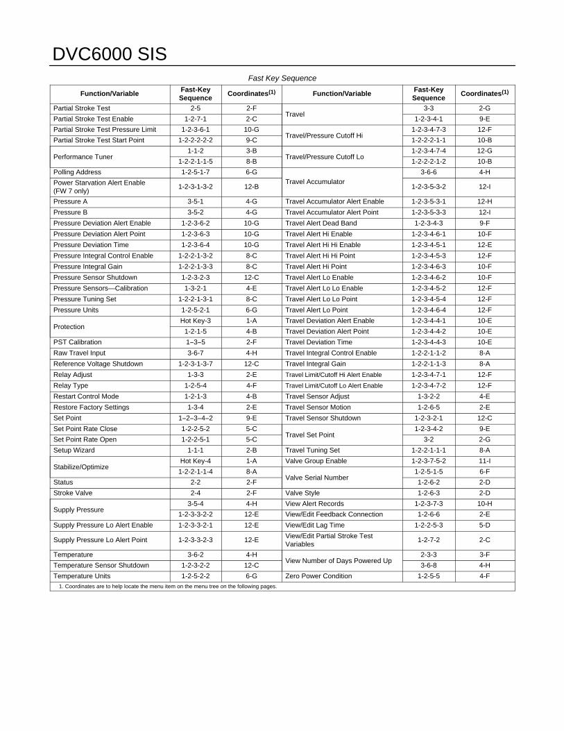
Fast Key Sequence
Function/Variable Fast-KeySequence
Coordinates(1) Function/Variable Fast-KeySequence
Coordinates(1)
Partial Stroke Test 2-5 2-FTravel
3-3 2-G
Partial Stroke Test Enable 1-2-7-1 2-C 1-2-3-4-1 9-E
Partial Stroke Test Pressure Limit 1-2-3-6-1 10-GTravel/Pressure Cutoff Hi
1-2-3-4-7-3 12-F
Partial Stroke Test Start Point 1-2-2-2-2-2 9-C 1-2-2-2-1-1 10-B
Performance Tuner1-1-2 3-B
Travel/Pressure Cutoff Lo1-2-3-4-7-4 12-G
1-2-2-1-1-5 8-B 1-2-2-2-1-2 10-B
Polling Address 1-2-5-1-7 6-GTravel Accumulator
3-6-6 4-H
Power Starvation Alert Enable(FW 7 only)
1-2-3-1-3-2 12-B 1-2-3-5-3-2 12-I
Pressure A 3-5-1 4-G Travel Accumulator Alert Enable 1-2-3-5-3-1 12-H
Pressure B 3-5-2 4-G Travel Accumulator Alert Point 1-2-3-5-3-3 12-I
Pressure Deviation Alert Enable 1-2-3-6-2 10-G Travel Alert Dead Band 1-2-3-4-3 9-F
Pressure Deviation Alert Point 1-2-3-6-3 10-G Travel Alert Hi Enable 1-2-3-4-6-1 10-F
Pressure Deviation Time 1-2-3-6-4 10-G Travel Alert Hi Hi Enable 1-2-3-4-5-1 12-E
Pressure Integral Control Enable 1-2-2-1-3-2 8-C Travel Alert Hi Hi Point 1-2-3-4-5-3 12-F
Pressure Integral Gain 1-2-2-1-3-3 8-C Travel Alert Hi Point 1-2-3-4-6-3 10-F
Pressure Sensor Shutdown 1-2-3-2-3 12-C Travel Alert Lo Enable 1-2-3-4-6-2 10-F
Pressure Sensors—Calibration 1-3-2-1 4-E Travel Alert Lo Lo Enable 1-2-3-4-5-2 12-F
Pressure Tuning Set 1-2-2-1-3-1 8-C Travel Alert Lo Lo Point 1-2-3-4-5-4 12-F
Pressure Units 1-2-5-2-1 6-G Travel Alert Lo Point 1-2-3-4-6-4 12-F
ProtectionHot Key-3 1-A Travel Deviation Alert Enable 1-2-3-4-4-1 10-E
1-2-1-5 4-B Travel Deviation Alert Point 1-2-3-4-4-2 10-E
PST Calibration 1−3−5 2-F Travel Deviation Time 1-2-3-4-4-3 10-E
Raw Travel Input 3-6-7 4-H Travel Integral Control Enable 1-2-2-1-1-2 8-A
Reference Voltage Shutdown 1-2-3-1-3-7 12-C Travel Integral Gain 1-2-2-1-1-3 8-A
Relay Adjust 1-3-3 2-E Travel Limit/Cutoff Hi Alert Enable 1-2-3-4-7-1 12-F
Relay Type 1-2-5-4 4-F Travel Limit/Cutoff Lo Alert Enable 1-2-3-4-7-2 12-F
Restart Control Mode 1-2-1-3 4-B Travel Sensor Adjust 1-3-2-2 4-E
Restore Factory Settings 1-3-4 2-E Travel Sensor Motion 1-2-6-5 2-E
Set Point 1−2−3−4−2 9-E Travel Sensor Shutdown 1-2-3-2-1 12-C
Set Point Rate Close 1-2-2-5-2 5-CTravel Set Point
1-2-3-4-2 9-E
Set Point Rate Open 1-2-2-5-1 5-C 3-2 2-G
Setup Wizard 1-1-1 2-B Travel Tuning Set 1-2-2-1-1-1 8-A
Stabilize/OptimizeHot Key-4 1-A Valve Group Enable 1-2-3-7-5-2 11-I
1-2-2-1-1-4 8-AValve Serial Number
1-2-5-1-5 6-F
Status 2-2 2-F 1-2-6-2 2-D
Stroke Valve 2-4 2-F Valve Style 1-2-6-3 2-D
Supply Pressure3-5-4 4-H View Alert Records 1-2-3-7-3 10-H
1-2-3-3-2-2 12-E View/Edit Feedback Connection 1-2-6-6 2-E
Supply Pressure Lo Alert Enable 1-2-3-3-2-1 12-E View/Edit Lag Time 1-2-2-5-3 5-D
Supply Pressure Lo Alert Point 1-2-3-3-2-3 12-E View/Edit Partial Stroke TestVariables
1-2-7-2 2-C
Temperature 3-6-2 4-HView Number of Days Powered Up
2-3-3 3-F
Temperature Sensor Shutdown 1-2-3-2-2 12-C 3-6-8 4-H
Temperature Units 1-2-5-2-2 6-G Zero Power Condition 1-2-5-5 4-F1. Coordinates are to help locate the menu item on the menu tree on the following pages.
DVC6000 SIS
iiiiii
Response Control
1 Tuning2 Travel/Pressure Control3 Input Characterization4 Custom Characterization Table5 Dynamic Response
Hot Key
1 Instrument Mode2 Control Mode3 Protection4 Stabilize/Optimize 1-1
1
1
1
1-2-1
1-2
1-2-4
1-2-1-4
1-2-5
1-2-6
1-3
1-3-1
1-3-2
2
3-5
3-6
1 2 3 4 5 6
2
2-3
1-2-7
1-2-3
3-7
3
1-2-2
1-2-5-2
1-2-5-3
1-2-2-1
1-2-2-2
1-2-2-5
1-2-5-9
1-2-5-1
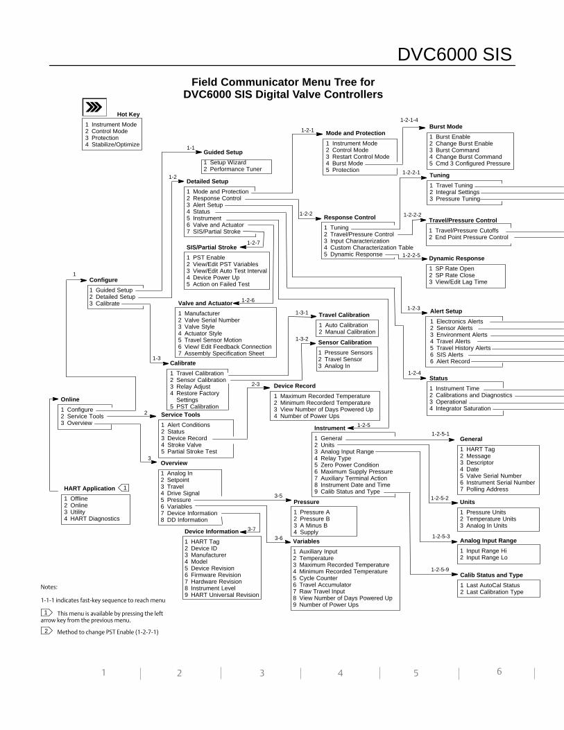
Guided Setup
1 Setup Wizard2 Performance Tuner
Detailed Setup
1 Mode and Protection2 Response Control3 Alert Setup4 Status5 Instrument6 Valve and Actuator7 SIS/Partial Stroke
Online
1 Configure2 Service Tools3 Overview
Configure
1 Guided Setup2 Detailed Setup3 Calibrate
HART Application
1 Offline2 Online3 Utility4 HART Diagnostics
Calibrate
1 Travel Calibration2 Sensor Calibration3 Relay Adjust4 Restore Factory 4 Settings5 PST Calibration
SIS/Partial Stroke
1 PST Enable2 View/Edit PST Variables3 View/Edit Auto Test Interval4 Device Power Up5 Action on Failed Test
Burst Mode
1 Burst Enable2 Change Burst Enable3 Burst Command4 Change Burst Command5 Cmd 3 Configured Pressure
Mode and Protection
1 Instrument Mode2 Control Mode3 Restart Control Mode4 Burst Mode5 Protection
Device Information
1 HART Tag2 Device ID3 Manufacturer4 Model5 Device Revision6 Firmware Revision7 Hardware Revision8 Instrument Level9 HART Universal Revision
Variables
1 Auxiliary Input2 Temperature3 Maximum Recorded Temperature4 Minimum Recorded Temperature5 Cycle Counter6 Travel Accumulator7 Raw Travel Input8 View Number of Days Powered Up9 Number of Power Ups
Pressure
1 Pressure A2 Pressure B3 A Minus B4 Supply
Service Tools
1 Alert Conditions2 Status3 Device Record4 Stroke Valve5 Partial Stroke Test
Overview
1 Analog In2 Setpoint3 Travel4 Drive Signal5 Pressure6 Variables7 Device Information8 DD Information
Device Record
1 Maximum Recorded Temperature2 Minimum Recorderd Temperature3 View Number of Days Powered Up4 Number of Power Ups
Travel Calibration
1 Auto Calibration2 Manual Calibration
Sensor Calibration
1 Pressure Sensors2 Travel Sensor3 Analog In
Alert Setup
1 Electronics Alerts2 Sensor Alerts3 Environment Alerts4 Travel Alerts5 Travel History Alerts6 SIS Alerts 6 Alert Record
Valve and Actuator
1 Manufacturer2 Valve Serial Number3 Valve Style4 Actuator Style5 Travel Sensor Motion6 View/ Edit Feedback Connection7 Assembly Specification Sheet
Tuning
1 Travel Tuning2 Integral Settings3 Pressure Tuning
Travel/Pressure Control
1 Travel/Pressure Cutoffs2 End Point Pressure Control
Dynamic Response
1 SP Rate Open2 SP Rate Close3 View/Edit Lag Time
Instrument
1 General2 Units3 Analog Input Range4 Relay Type5 Zero Power Condition6 Maximum Supply Pressure7 Auxiliary Terminal Action8 Instrument Date and Time9 Calib Status and Type
Status
1 Instrument Time2 Calibrations and Diagnostics3 Operational4 Integrator Saturation
Units
1 Pressure Units2 Temperature Units3 Analog In Units
Analog Input Range
1 Input Range Hi2 Input Range Lo
Calib Status and Type
1 Last AutoCal Status2 Last Calibration Type
General
1 HART Tag2 Message3 Descriptor4 Date5 Valve Serial Number6 Instrument Serial Number7 Polling Address
Notes:
1‐1‐1 indicates fast‐key sequence to reach menu
This menu is available by pressing the leftarrow key from the previous menu.
Method to change PST Enable (1‐2‐7‐1)
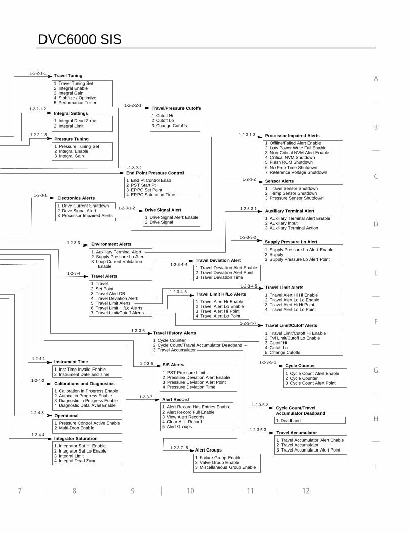
Field Communicator Menu Tree forDVC6000 SIS Digital Valve Controllers
DVC6000 SIS
iv iv
7 8 9 10 11
A
B
C
D
E
F
G
H
I
12
Electronics Alerts
1 Drive Current Shutdown2 Drive Signal Alert3 Processor Impaired Alerts
Travel Tuning
1 Travel Tuning Set2 Integral Enable3 Integral Gain4 Stabilize / Optimize5 Performance Tuner
Integral Settings
1 Integral Dead Zone2 Integral Limit
Pressure Tuning
1 Pressure Tuning Set2 Integral Enable3 Integral Gain
Travel/Pressure Cutoffs
1 Cutoff Hi2 Cutoff Lo3 Change Cutoffs
Drive Signal Alert
1 Drive Signal Alert Enable2 Drive Signal
Processor Impaired Alerts
1 Offline/Failed Alert Enable2 Low Power Write Fail Enable3 Non-Critical NVM Alert Enable4 Critical NVM Shutdown5 Flash ROM Shutdown6 No Free Time Shutdown7 Reference Voltage Shutdown
Sensor Alerts
1 Travel Sensor Shutdown2 Temp Sensor Shutdown3 Pressure Sensor Shutdown
Environment Alerts
1 Auxiliary Terminal Alert2 Supply Pressure Lo Alert3 Loop Current Validation
Enable
Travel Limit Alerts
1 Travel Alert Hi Hi Enable2 Travel Alert Lo Lo Enable3 Travel Alert Hi Hi Point4 Travel Alert Lo Lo Point
Travel Alerts
1 Travel2 Set Point3 Travel Alert DB4 Travel Deviation Alert5 Travel Limit Alerts6 Travel Limit Hi/Lo Alerts7 Travel Limit/Cutoff Alerts
Travel History Alerts
1 Cycle Counter2 Cycle Count/Travel Accumulator Deadband3 Travel Accumulator
Travel Limit Hi/Lo Alerts
1 Travel Alert Hi Enable2 Travel Alert Lo Enable3 Travel Alert Hi Point4 Travel Alert Lo Point
Travel Limit/Cutoff Alerts
1 Travel Limit/Cutoff Hi Enable2 Tvl Limit/Cutoff Lo Enable3 Cutoff Hi4 Cutoff Lo5 Change Cutoffs
Integrator Saturation
1 Integrator Sat Hi Enable2 Integrator Sat Lo Enable3 Integral Limit4 Integral Dead Zone
Travel Deviation Alert
1 Travel Deviation Alert Enable2 Travel Deviation Alert Point3 Travel Deviation Time
Travel Accumulator
1 Travel Accumulator Alert Enable2 Travel Accumulator3 Travel Accumulator Alert Point
Cycle Counter
1 Cycle Count Alert Enable2 Cycle Counter3 Cycle Count Alert Point
Instrument Time
1 Inst Time Invalid Enable2 Instrument Date and Time
Calibrations and Diagnostics
1 Calibration in Progress Enable2 Autocal in Progress Enable3 Diagnostic in Progress Enable4 Diagnostic Data Avail Enable
Operational
1 Pressure Control Active Enable2 Multi-Drop Enable
1-2-2-1-1
1-2-2-2-1
1-2-3-1
1-2-3-1-2
End Point Pressure Control
1 End Pt Control Enab2 PST Start Pt3 EPPC Set Point4 EPPC Saturation Time
1-2-2-2-2
SIS Alerts
1 PST Pressure Limit2 Pressure Deviation Alert Enable3 Pressure Deviation Alert Point4 Pressure Deviation Time
Supply Pressure Lo Alert
1 Supply Pressure Lo Alert Enable2 Supply3 Supply Pressure Lo Alert Point
Auxiliary Terminal Alert
1 Auxiliary Terminal Alert Enable2 Auxiliary Input3 Auxiliary Terminal Action
Alert Record
1 Alert Record Has Entries Enable2 Alert Record Full Enable3 View Alert Records4 Clear ALL Record5 Alert Groups
Alert Groups
1 Failure Group Enable2 Valve Group Enable3 Miscellaneous Group Enable
Cycle Count/TravelAccumulator Deadband
1 Deadband
1-2-3-6
1-2-3-2
1-2-3-3
1-2-3-5
1-2-3-7
1-2-2-1-2
1-2-2-1-3
1-2-3-5-1
1-2-3-7−5
1-2-4-2
1-2-4-3
1-2-4-4
1-2-4-1
1-2-3-5-3
1-2-3-5-2
1-2-3-1-3
1-2-3-4
1-2-3-3-1
1-2-3-3-2
1-2-3-4-4
1-2-3-4-51-2-3-4-6
1-2-3-4-7
DVC6000 SIS
vv
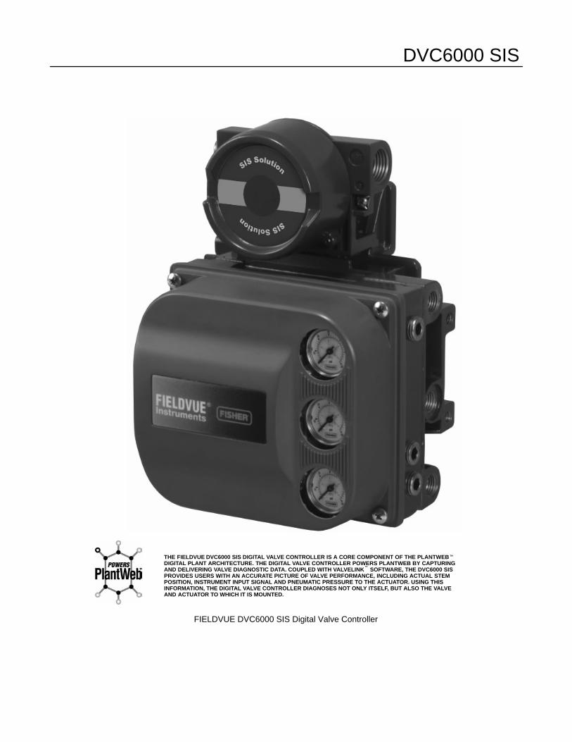
FIELDVUE DVC6000 SIS Digital Valve Controller
THE FIELDVUE DVC6000 SIS DIGITAL VALVE CONTROLLER IS A CORE COMPONENT OF THE PLANTWEB�DIGITAL PLANT ARCHITECTURE. THE DIGITAL VALVE CONTROLLER POWERS PLANTWEB BY CAPTURINGAND DELIVERING VALVE DIAGNOSTIC DATA. COUPLED WITH VALVELINK� SOFTWARE, THE DVC6000 SISPROVIDES USERS WITH AN ACCURATE PICTURE OF VALVE PERFORMANCE, INCLUDING ACTUAL STEMPOSITION, INSTRUMENT INPUT SIGNAL AND PNEUMATIC PRESSURE TO THE ACTUATOR. USING THISINFORMATION, THE DIGITAL VALVE CONTROLLER DIAGNOSES NOT ONLY ITSELF, BUT ALSO THE VALVEAND ACTUATOR TO WHICH IT IS MOUNTED.
Introduction and Specifications
September 2013 1-1
1-1
Section 1 Introduction and Specifications
Scope of Manual 1-2. . . . . . . . . . . . . . . . . . . . . . . . . . . . . . . . . . . . . . . . . . . . . . . . . . . . . . . .
Conventions Used in this Manual 1-2. . . . . . . . . . . . . . . . . . . . . . . . . . . . . . . . . . . . .
Description 1-2. . . . . . . . . . . . . . . . . . . . . . . . . . . . . . . . . . . . . . . . . . . . . . . . . . . . . . . . . . . . . .
Specifications 1-3. . . . . . . . . . . . . . . . . . . . . . . . . . . . . . . . . . . . . . . . . . . . . . . . . . . . . . . . . . .
Related Documents 1-7. . . . . . . . . . . . . . . . . . . . . . . . . . . . . . . . . . . . . . . . . . . . . . . . . . . . .
Educational Services 1-7. . . . . . . . . . . . . . . . . . . . . . . . . . . . . . . . . . . . . . . . . . . . . . . . . . .
1
DVC6000 SIS
September 20131-2
Table 1-1. FIELDVUE DVC6000 SIS CapabilitiesAuto Calibration
Custom Characterization
Alerts
Step Response, Drive Signal Test & Dynamic Error Band
Advanced Diagnostics (Valve Signature)
Performance Tuner
Performance Diagnostics(1)
Solenoid Valve Health Monitoring(1)
Partial Stroke Testing1. Available in Firmware Revision 7 and higher.
Scope of ManualThis instruction manual includes specifications andinstallation, operation, and maintenance informationfor FIELDVUE DVC6000 SIS digital valve controllersfor Safety Instrumented System (SIS) Solutions,device revision 1, firmware revision 3−6 or devicerevision 2, firmware 7, 9, 10, and 11.
This instruction manual describes using the 475 FieldCommunicator with device description revision 8, usedwith DVC6000 SIS device revision 2, firmware revision7, 9, 10, or 11 to setup and calibrate the instrument.You can also use Fisher ValveLink� software version7.3 or higher to setup, calibrate, and diagnose thevalve and instrument. For information on usingValveLink software with the instrument, refer to theValveLink software help or documentation.
Do not install, operate, or maintain a DVC6000 SISdigital valve controller without being fully trained andqualified in valve, actuator, and accessory installation,operation, and maintenance. To avoid personalinjury or property damage, it is important tocarefully read, understand, and follow all of thecontents of this manual, including all safetycautions and warnings. If you have any questionsabout these instructions, contact your EmersonProcess Management sales office before proceeding
Conventions Used in this Manual
Procedures that require the use of a FieldCommunicator have the Field Communicator symbolin the heading.
Procedures that are accessible with the Hot Keyon the Field Communicator will also have the Hot Keysymbol in the heading.
Some of the procedures also contain the sequence ofnumeric keys required to display the desired FieldCommunicator menu. For example, to access DeviceSetup, from the Online menu, press 2 (selects
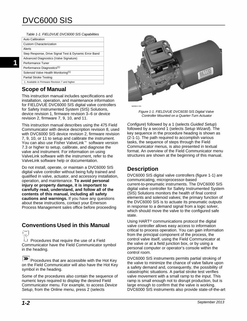
Figure 1-1. FIELDVUE DVC6030 SIS Digital Valve Controller Mounted on a Quarter-Turn Actuator
W8308-3 SIS
Configure) followed by a 1 (selects Guided Setup)followed by a second 1 (selects Setup Wizard). Thekey sequence in the procedure heading is shown as(2-1-1). The path required to accomplish varioustasks, the sequence of steps through the FieldCommunicator menus, is also presented in textualformat. An overview of the Field Communicator menustructures are shown at the beginning of this manual.
Description DVC6000 SIS digital valve controllers (figure 1-1) arecommunicating, microprocessor-basedcurrent-to-pneumatic instruments. The DVC6000 SISdigital valve controller for Safety Instrumented System(SIS) Solutions monitors the health of final controlelements and solenoid valves; the primary function ofthe DVC6000 SIS is to actuate its pneumatic outputsin response to a demand signal from a logic solver,which should move the valve to the configured safestate.
Using HART� communications protocol the digitalvalve controller allows easy access to informationcritical to process operation. You can gain informationfrom the principal component of the process, thecontrol valve itself, using the Field Communicator atthe valve or at a field junction box, or by using apersonal computer or operator’s console within thecontrol room.
DVC6000 SIS instruments permits partial stroking ofthe valve to minimize the chance of valve failure upona safety demand and, consequently, the possibility ofcatastrophic situations. A partial stroke test verifiesvalve movement with a small ramp to the input. Thisramp is small enough not to disrupt production, but islarge enough to confirm that the valve is working.DVC6000 SIS instruments also provide state-of-the-art
1
Introduction and Specifications
September 2013 1-3
testing methods, which reduce testing andmaintenance time, improve system performance, andprovide diagnostic capabilities.
Using a personal computer and ValveLink software,AMS Suite: Intelligent Device Manager, or a FieldCommunicator, you can perform several operationswith the DVC6000 SIS digital valve controller. You canobtain general information concerning softwarerevision level, messages, tag, descriptor, and date.Diagnostic information is available to aid you whentroubleshooting. Input and output configurationparameters can be set, and the digital valve controllercan be calibrated. Refer to table 1-1 for details on thecapabilities of the DVC6000 SIS.
Using the HART protocol, information from the fieldcan be integrated into control systems or be receivedon a single loop basis.
Specifications
WARNING
Refer to table 1-2 for applicationspecifications. Incorrect configurationof a positioning instrument couldresult in the malfunction of theproduct, property damage or personalinjury.
Specifications for DVC6000 SIS digital valvecontrollers are shown in table 1-2. Specifications forthe Field Communicator can be found in the productmanual for the Field Communicator.
1
DVC6000 SIS
September 20131-4
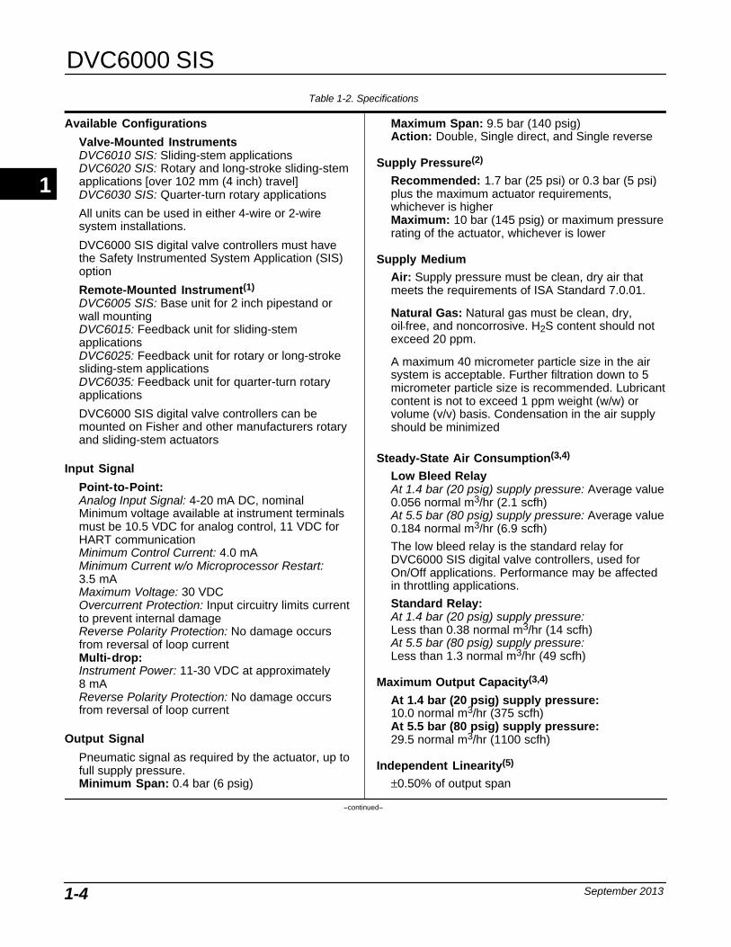
Table 1-2. Specifications
Available Configurations
Valve-Mounted InstrumentsDVC6010 SIS: Sliding-stem applicationsDVC6020 SIS: Rotary and long-stroke sliding-stemapplications [over 102 mm (4 inch) travel]DVC6030 SIS: Quarter-turn rotary applications
All units can be used in either 4-wire or 2-wiresystem installations.
DVC6000 SIS digital valve controllers must havethe Safety Instrumented System Application (SIS)option
Remote-Mounted Instrument(1)
DVC6005 SIS: Base unit for 2 inch pipestand orwall mountingDVC6015: Feedback unit for sliding-stemapplicationsDVC6025: Feedback unit for rotary or long-strokesliding-stem applicationsDVC6035: Feedback unit for quarter-turn rotaryapplications
DVC6000 SIS digital valve controllers can bemounted on Fisher and other manufacturers rotaryand sliding-stem actuators
Input Signal
Point-to-Point:Analog Input Signal: 4-20 mA DC, nominalMinimum voltage available at instrument terminalsmust be 10.5 VDC for analog control, 11 VDC forHART communicationMinimum Control Current: 4.0 mAMinimum Current w/o Microprocessor Restart:3.5 mAMaximum Voltage: 30 VDCOvercurrent Protection: Input circuitry limits currentto prevent internal damageReverse Polarity Protection: No damage occursfrom reversal of loop currentMulti-drop:Instrument Power: 11-30 VDC at approximately8 mAReverse Polarity Protection: No damage occursfrom reversal of loop current
Output Signal
Pneumatic signal as required by the actuator, up tofull supply pressure.Minimum Span: 0.4 bar (6 psig)
Maximum Span: 9.5 bar (140 psig)Action: Double, Single direct, and Single reverse
Supply Pressure(2)
Recommended: 1.7 bar (25 psi) or 0.3 bar (5 psi)plus the maximum actuator requirements,whichever is higherMaximum: 10 bar (145 psig) or maximum pressurerating of the actuator, whichever is lower
Supply Medium
Air: Supply pressure must be clean, dry air thatmeets the requirements of ISA Standard 7.0.01.
Natural Gas: Natural gas must be clean, dry,oil-free, and noncorrosive. H2S content should notexceed 20 ppm.
A maximum 40 micrometer particle size in the airsystem is acceptable. Further filtration down to 5micrometer particle size is recommended. Lubricantcontent is not to exceed 1 ppm weight (w/w) orvolume (v/v) basis. Condensation in the air supplyshould be minimized
Steady-State Air Consumption(3,4)
Low Bleed RelayAt 1.4 bar (20 psig) supply pressure: Average value0.056 normal m3/hr (2.1 scfh)At 5.5 bar (80 psig) supply pressure: Average value0.184 normal m3/hr (6.9 scfh)
The low bleed relay is the standard relay forDVC6000 SIS digital valve controllers, used forOn/Off applications. Performance may be affectedin throttling applications.
Standard Relay:At 1.4 bar (20 psig) supply pressure: Less than 0.38 normal m3/hr (14 scfh)At 5.5 bar (80 psig) supply pressure: Less than 1.3 normal m3/hr (49 scfh)
Maximum Output Capacity(3,4)
At 1.4 bar (20 psig) supply pressure: 10.0 normal m3/hr (375 scfh)At 5.5 bar (80 psig) supply pressure: 29.5 normal m3/hr (1100 scfh)
Independent Linearity(5)
±0.50% of output span
−continued−
1
Introduction and Specifications
September 2013 1-5
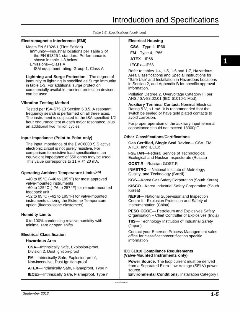
Table 1-2. Specifications (continued)
Electromagnetic Interference (EMI)
Meets EN 61326-1 (First Edition)Immunity—Industrial locations per Table 2 of
the EN 61326-1 standard. Performance isshown in table 1-3 below.
Emissions—Class AISM equipment rating: Group 1, Class A
Lightning and Surge Protection—The degree ofimmunity to lightning is specified as Surge immunityin table 1-3. For additional surge protectioncommercially available transient protection devicescan be used.
Vibration Testing Method
Tested per ISA-S75.13 Section 5.3.5. A resonantfrequency search is performed on all three axes.The instrument is subjected to the ISA specified 1/2hour endurance test at each major resonance, plusan additional two million cycles.
Input Impedance (Point-to-Point only)
The input impedance of the DVC6000 SIS activeelectronic circuit is not purely resistive. Forcomparison to resistive load specifications, anequivalent impedance of 550 ohms may be used.This value corresponds to 11 V @ 20 mA.
Operating Ambient Temperature Limits(2,6)
−40 to 85�C (−40 to 185�F) for most approvedvalve-mounted instruments−60 to 125�C (−76 to 257�F) for remote-mountedfeedback unit−52 to 85�C (−62 to 185�F) for valve-mountedinstruments utilizing the Extreme Temperatureoption (fluorosilicone elastomers)
Humidity Limits
0 to 100% condensing relative humidity withminimal zero or span shifts
Electrical Classification
Hazardous Area
CSA—Intrinsically Safe, Explosion-proof, Division 2, Dust Ignition-proof
FM—Intrinsically Safe, Explosion-proof,Non-incendive, Dust Ignition-proof
ATEX—Intrinsically Safe, Flameproof, Type n
IECEx—Intrinsically Safe, Flameproof, Type n
Electrical Housing
CSA—Type 4, IP66
FM—Type 4, IP66
ATEX—IP66
IECEx—IP66
Refer to tables 1-4, 1-5, 1-6 and 1-7, HazardousArea Classifications and Special Instructions for“Safe Use” and Installation in Hazardous Locationsin Section 2, and Appendix B for specific approvalinformation.
Pollution Degree 2, Overvoltage Category III perANSI/ISA-82.02.01 (IEC 61010-1 Mod).
Auxiliary Terminal Contact: Nominal ElectricalRating 5 V, <1 mA; It is recommended that theswitch be sealed or have gold plated contacts toavoid corrosion.
For proper operation of the auxiliary input terminalcapacitance should not exceed 18000pF.
Other Classifications/Certifications
Gas Certified, Single Seal Device— CSA, FM,ATEX, and IECEx
FSETAN—Federal Service of Technological,Ecological and Nuclear Inspectorate (Russia)
GOST-R—Russian GOST-R
INMETRO— National Institute of Metrology,Quality, and Technology (Brazil)
KGS—Korea Gas Safety Corporation (South Korea)
KISCO—Korea Industrial Safety Corporation (SouthKorea)
NEPSI— National Supervision and InspectionCentre for Explosion Protection and Safety ofInstrumentation (China)
PESO CCOE— Petroleum and Explosives SafetyOrganisation − Chief Controller of Explosives (India)
TIIS— Technology Institution of Industrial Safety(Japan)
Contact your Emerson Process Management salesoffice for classification/certification specificinformation
IEC 61010 Compliance Requirements(Valve-Mounted Instruments only)
Power Source: The loop current must be derivedfrom a Separated Extra-Low Voltage (SELV) powersource.Environmental Conditions: Installation Category I
−continued−
1
DVC6000 SIS
September 20131-6
Table 1-2. Specifications (continued)
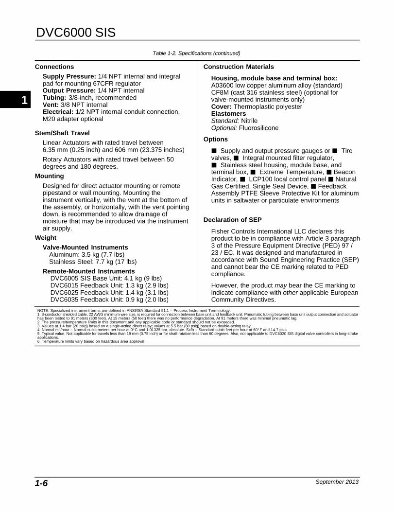
Connections
Supply Pressure: 1/4 NPT internal and integralpad for mounting 67CFR regulatorOutput Pressure: 1/4 NPT internalTubing: 3/8-inch, recommendedVent: 3/8 NPT internalElectrical: 1/2 NPT internal conduit connection,M20 adapter optional
Stem/Shaft Travel
Linear Actuators with rated travel between 6.35 mm (0.25 inch) and 606 mm (23.375 inches)
Rotary Actuators with rated travel between 50degrees and 180 degrees.
Mounting
Designed for direct actuator mounting or remotepipestand or wall mounting. Mounting theinstrument vertically, with the vent at the bottom ofthe assembly, or horizontally, with the vent pointingdown, is recommended to allow drainage ofmoisture that may be introduced via the instrumentair supply.
Weight
Valve-Mounted InstrumentsAluminum: 3.5 kg (7.7 lbs)Stainless Steel: 7.7 kg (17 lbs)
Remote-Mounted InstrumentsDVC6005 SIS Base Unit: 4.1 kg (9 lbs)DVC6015 Feedback Unit: 1.3 kg (2.9 lbs)DVC6025 Feedback Unit: 1.4 kg (3.1 lbs)DVC6035 Feedback Unit: 0.9 kg (2.0 lbs)
Construction Materials
Housing, module base and terminal box:A03600 low copper aluminum alloy (standard)CF8M (cast 316 stainless steel) (optional forvalve-mounted instruments only)Cover: Thermoplastic polyesterElastomersStandard: Nitrile Optional: Fluorosilicone
Options
� Supply and output pressure gauges or � Tirevalves, � Integral mounted filter regulator,� Stainless steel housing, module base, andterminal box, � Extreme Temperature, � BeaconIndicator, � LCP100 local control panel � NaturalGas Certified, Single Seal Device, � FeedbackAssembly PTFE Sleeve Protective Kit for aluminumunits in saltwater or particulate environments
Declaration of SEP
Fisher Controls International LLC declares thisproduct to be in compliance with Article 3 paragraph3 of the Pressure Equipment Directive (PED) 97 /23 / EC. It was designed and manufactured inaccordance with Sound Engineering Practice (SEP)and cannot bear the CE marking related to PEDcompliance.
However, the product may bear the CE marking toindicate compliance with other applicable EuropeanCommunity Directives.
NOTE: Specialized instrument terms are defined in ANSI/ISA Standard 51.1 − Process Instrument Terminology.1. 3-conductor shielded cable, 22 AWG minimum wire size, is required for connection between base unit and feedback unit. Pneumatic tubing between base unit output connection and actuatorhas been tested to 91 meters (300 feet). At 15 meters (50 feet) there was no performance degradation. At 91 meters there was minimal pneumatic lag.2. The pressure/temperature limits in this document and any applicable code or standard should not be exceeded.3. Values at 1.4 bar (20 psig) based on a single-acting direct relay; values at 5.5 bar (80 psig) based on double-acting relay.4. Normal m3/hour − Normal cubic meters per hour at 0�C and 1.01325 bar, absolute. Scfh − Standard cubic feet per hour at 60�F and 14.7 psia5. Typical value. Not applicable for travels less than 19 mm (0.75 inch) or for shaft rotation less than 60 degrees. Also, not applicable to DVC6020 SIS digital valve controllers in long-strokeapplications.6. Temperature limits vary based on hazardous area approval
1
Introduction and Specifications
September 2013 1-7
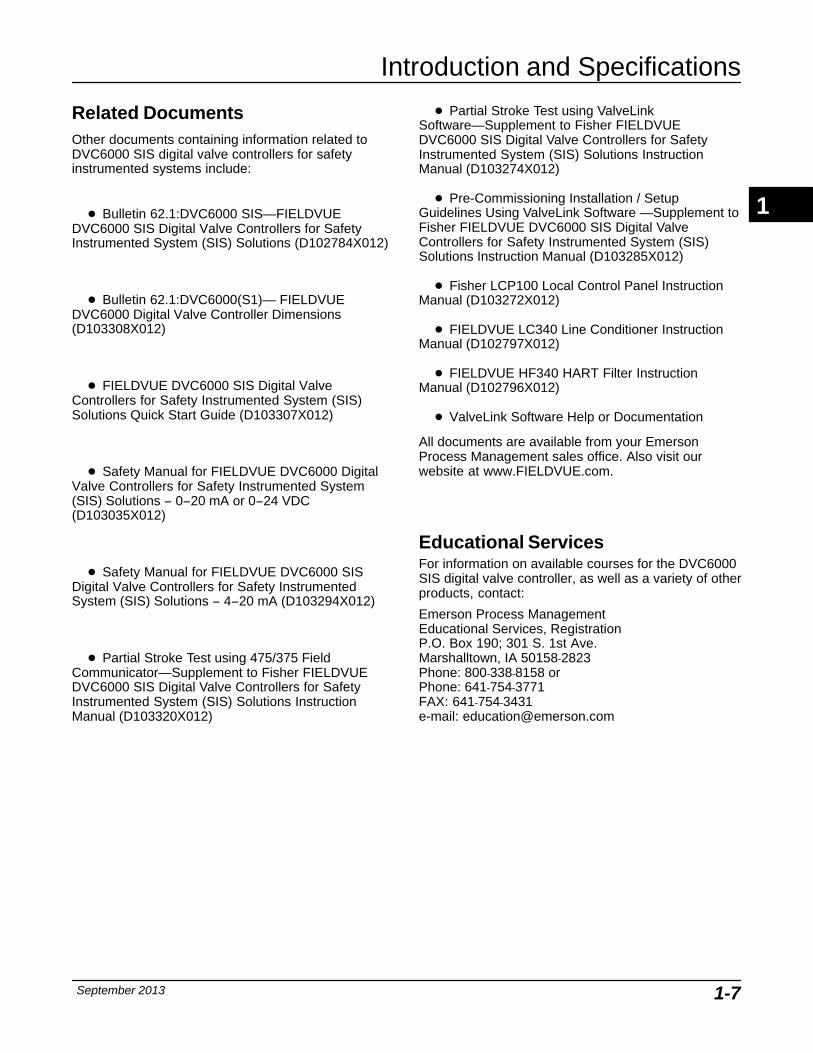
Related DocumentsOther documents containing information related toDVC6000 SIS digital valve controllers for safetyinstrumented systems include:
� Bulletin 62.1:DVC6000 SIS—FIELDVUEDVC6000 SIS Digital Valve Controllers for SafetyInstrumented System (SIS) Solutions (D102784X012)
� Bulletin 62.1:DVC6000(S1)— FIELDVUEDVC6000 Digital Valve Controller Dimensions(D103308X012)
� FIELDVUE DVC6000 SIS Digital ValveControllers for Safety Instrumented System (SIS)Solutions Quick Start Guide (D103307X012)
� Safety Manual for FIELDVUE DVC6000 DigitalValve Controllers for Safety Instrumented System(SIS) Solutions − 0−20 mA or 0−24 VDC(D103035X012)
� Safety Manual for FIELDVUE DVC6000 SISDigital Valve Controllers for Safety InstrumentedSystem (SIS) Solutions − 4−20 mA (D103294X012)
� Partial Stroke Test using 475/375 FieldCommunicator—Supplement to Fisher FIELDVUEDVC6000 SIS Digital Valve Controllers for SafetyInstrumented System (SIS) Solutions InstructionManual (D103320X012)
� Partial Stroke Test using ValveLinkSoftware—Supplement to Fisher FIELDVUEDVC6000 SIS Digital Valve Controllers for SafetyInstrumented System (SIS) Solutions InstructionManual (D103274X012)
� Pre-Commissioning Installation / SetupGuidelines Using ValveLink Software —Supplement toFisher FIELDVUE DVC6000 SIS Digital ValveControllers for Safety Instrumented System (SIS)Solutions Instruction Manual (D103285X012)
� Fisher LCP100 Local Control Panel InstructionManual (D103272X012)
� FIELDVUE LC340 Line Conditioner InstructionManual (D102797X012)
� FIELDVUE HF340 HART Filter InstructionManual (D102796X012)
� ValveLink Software Help or Documentation
All documents are available from your EmersonProcess Management sales office. Also visit ourwebsite at www.FIELDVUE.com.
Educational Services For information on available courses for the DVC6000SIS digital valve controller, as well as a variety of otherproducts, contact:
Emerson Process ManagementEducational Services, RegistrationP.O. Box 190; 301 S. 1st Ave.Marshalltown, IA 50158-2823Phone: 800-338-8158 orPhone: 641-754-3771 FAX: 641-754-3431e-mail: [email protected]
1
DVC6000 SIS
September 20131-8
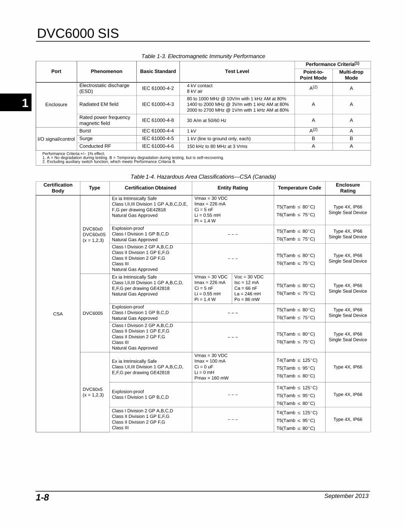
Table 1-3. Electromagnetic Immunity Performance
Port Phenomenon Basic Standard Test LevelPerformance Criteria(1)
Point-to-Point Mode
Multi-dropMode
Enclosure
Electrostatic discharge(ESD)
IEC 61000-4-2 4 kV contact8 kV air
A(2) A
Radiated EM field IEC 61000-4-380 to 1000 MHz @ 10V/m with 1 kHz AM at 80%1400 to 2000 MHz @ 3V/m with 1 kHz AM at 80%2000 to 2700 MHz @ 1V/m with 1 kHz AM at 80%
A A
Rated power frequencymagnetic field
IEC 61000-4-8 30 A/m at 50/60 Hz A A
I/O signal/control
Burst IEC 61000-4-4 1 kV A(2) A
Surge IEC 61000-4-5 1 kV (line to ground only, each) B B
Conducted RF IEC 61000-4-6 150 kHz to 80 MHz at 3 Vrms A APerformance Criteria:+/− 1% effect. 1. A = No degradation during testing. B = Temporary degradation during testing, but is self-recovering.2. Excluding auxiliary switch function, which meets Performance Criteria B.
Table 1-4. Hazardous Area Classifications—CSA (Canada)Certification
BodyType Certification Obtained Entity Rating Temperature Code Enclosure
Rating
CSA
DVC60x0DVC60x0S(x = 1,2,3)
Ex ia Intrinsically SafeClass I,II,III Division 1 GP A,B,C,D,E,F,G per drawing GE42818Natural Gas Approved
Vmax = 30 VDCImax = 226 mACi = 5 nFLi = 0.55 mHPi = 1.4 W
T5(Tamb � 80�C)
T6(Tamb � 75�C)
Type 4X, IP66Single Seal Device
Explosion-proofClass I Division 1 GP B,C,DNatural Gas Approved
− − −T5(Tamb � 80�C)
T6(Tamb � 75�C)
Type 4X, IP66Single Seal Device
Class I Division 2 GP A,B,C,DClass II Division 1 GP E,F,GClass II Division 2 GP F,GClass IIINatural Gas Approved
− − −T5(Tamb � 80�C)
T6(Tamb � 75�C)
Type 4X, IP66Single Seal Device
DVC6005
Ex ia Intrinsically SafeClass I,II,III Division 1 GP A,B,C,D,E,F,G per drawing GE42818Natural Gas Approved
Vmax = 30 VDCImax = 226 mACi = 5 nFLi = 0.55 mHPi = 1.4 W
Voc = 30 VDCIsc = 12 mACa = 66 nFLa = 246 mHPo = 86 mW
T5(Tamb � 80�C)
T6(Tamb � 75�C)
Type 4X, IP66Single Seal Device
Explosion-proofClass I Division 1 GP B,C,DNatural Gas Approved
− − −T5(Tamb � 80�C)
T6(Tamb � 75�C)
Type 4X, IP66Single Seal Device
Class I Division 2 GP A,B,C,DClass II Division 1 GP E,F,GClass II Division 2 GP F,GClass III Natural Gas Approved
− − −T5(Tamb � 80�C)
T6(Tamb � 75�C)
Type 4X, IP66Single Seal Device
DVC60x5(x = 1,2,3)
Ex ia Intrinsically SafeClass I,II,III Division 1 GP A,B,C,D,E,F,G per drawing GE42818
Vmax = 30 VDCImax = 100 mACi = 0 uFLi = 0 mHPmax = 160 mW
T4(Tamb � 125�C)
T5(Tamb � 95�C)
T6(Tamb � 80�C)
Type 4X, IP66
Explosion-proofClass I Division 1 GP B,C,D
− − −T4(Tamb � 125�C)
T5(Tamb � 95�C)
T6(Tamb � 80�C)
Type 4X, IP66
Class I Division 2 GP A,B,C,DClass II Division 1 GP E,F,GClass II Division 2 GP F,GClass III
− − −T4(Tamb � 125�C)
T5(Tamb � 95�C)
T6(Tamb � 80�C)
Type 4X, IP66
1
Introduction and Specifications
September 2013 1-9
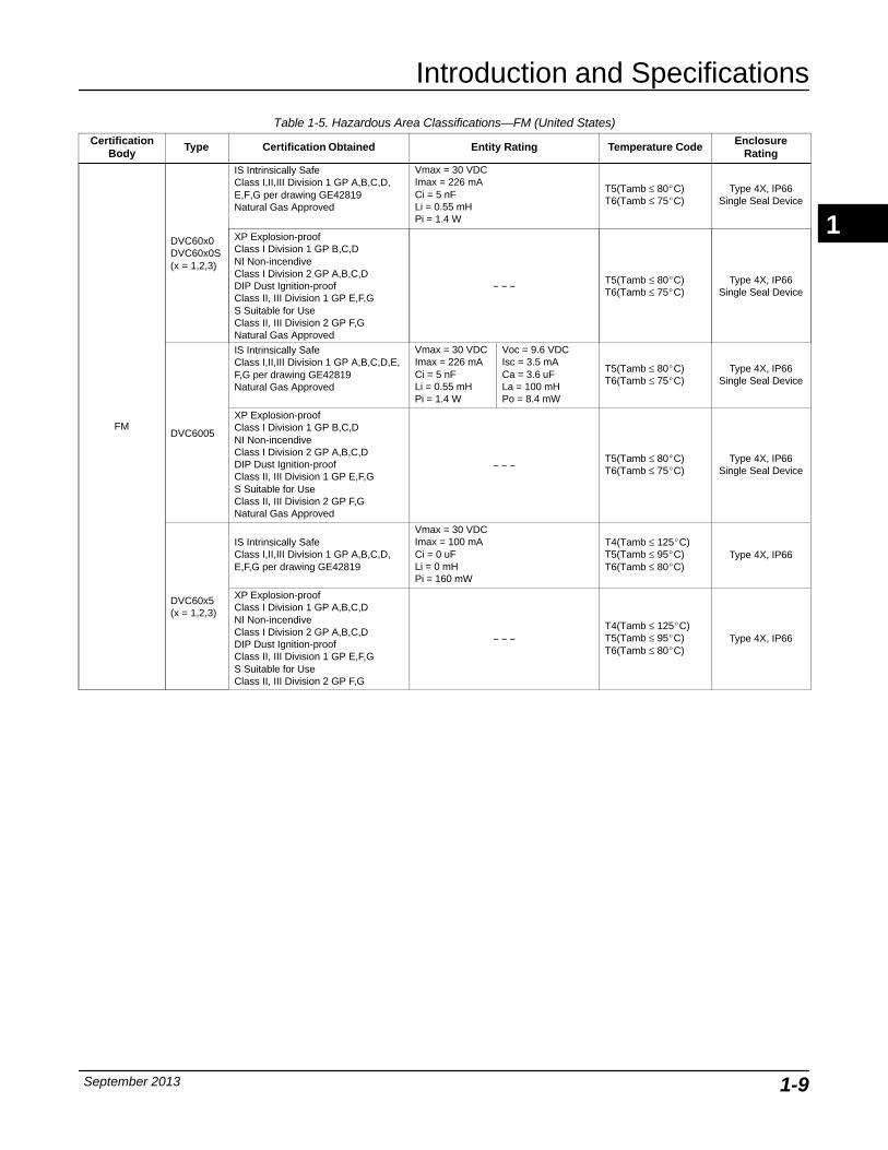
Table 1-5. Hazardous Area Classifications—FM (United States)Certification
BodyType Certification Obtained Entity Rating Temperature Code Enclosure
Rating
FM
DVC60x0DVC60x0S(x = 1,2,3)
IS Intrinsically SafeClass I,II,III Division 1 GP A,B,C,D,E,F,G per drawing GE42819Natural Gas Approved
Vmax = 30 VDCImax = 226 mACi = 5 nFLi = 0.55 mHPi = 1.4 W
T5(Tamb ≤ 80�C)T6(Tamb ≤ 75�C)
Type 4X, IP66Single Seal Device
XP Explosion-proofClass I Division 1 GP B,C,DNI Non-incendiveClass I Division 2 GP A,B,C,DDIP Dust Ignition-proofClass II, III Division 1 GP E,F,GS Suitable for UseClass II, III Division 2 GP F,G Natural Gas Approved
− − − T5(Tamb ≤ 80�C)T6(Tamb ≤ 75�C)
Type 4X, IP66Single Seal Device
DVC6005
IS Intrinsically SafeClass I,II,III Division 1 GP A,B,C,D,E,F,G per drawing GE42819Natural Gas Approved
Vmax = 30 VDCImax = 226 mACi = 5 nFLi = 0.55 mHPi = 1.4 W
Voc = 9.6 VDCIsc = 3.5 mACa = 3.6 uFLa = 100 mHPo = 8.4 mW
T5(Tamb ≤ 80�C)T6(Tamb ≤ 75�C)
Type 4X, IP66Single Seal Device
XP Explosion-proofClass I Division 1 GP B,C,DNI Non-incendiveClass I Division 2 GP A,B,C,DDIP Dust Ignition-proofClass II, III Division 1 GP E,F,GS Suitable for UseClass II, III Division 2 GP F,GNatural Gas Approved
− − −T5(Tamb ≤ 80�C)T6(Tamb ≤ 75�C)
Type 4X, IP66Single Seal Device
DVC60x5(x = 1,2,3)
IS Intrinsically SafeClass I,II,III Division 1 GP A,B,C,D,E,F,G per drawing GE42819
Vmax = 30 VDCImax = 100 mACi = 0 uFLi = 0 mHPi = 160 mW
T4(Tamb ≤ 125�C)T5(Tamb ≤ 95�C)T6(Tamb ≤ 80�C)
Type 4X, IP66
XP Explosion-proofClass I Division 1 GP A,B,C,DNI Non-incendiveClass I Division 2 GP A,B,C,DDIP Dust Ignition-proofClass II, III Division 1 GP E,F,GS Suitable for UseClass II, III Division 2 GP F,G
− − −T4(Tamb ≤ 125�C)T5(Tamb ≤ 95�C)T6(Tamb ≤ 80�C)
Type 4X, IP66
1
DVC6000 SIS
September 20131-10
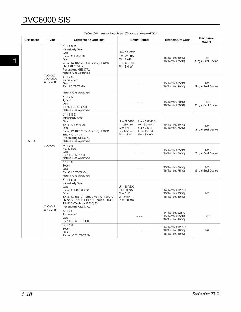
Table 1-6. Hazardous Area Classifications—ATEX
Certificate Type Certification Obtained Entity Rating Temperature Code EnclosureRating
ATEX
DVC60x0DVC60x0S(x = 1,2,3)
II 1 G DIntrinsically SafeGasEx ia IIC T5/T6 GaDustEx ia IIIC T85�C (Ta ≤ +73�C), T92�C (Ta ≤ +80�C) DaPer drawing GE60771Natural Gas Approved
Ui = 30 VDCIi = 226 mACi = 5 nFLi = 0.55 mHPi = 1.4 W
T5(Tamb ≤ 80�C)T6(Tamb ≤ 75�C)
IP66Single Seal Device
II 2 GFlameproofGasEx d IIC T5/T6 Gb
Natural Gas Approved
− − −T5(Tamb ≤ 85�C)T6(Tamb ≤ 80�C)
IP66Single Seal Device
II 3 GType nGasEx nC IIC T5/T6 GcNatural Gas Approved
− − −T5(Tamb ≤ 80�C)T6(Tamb ≤ 75�C)
IP66Single Seal Device
DVC6005
II 1 G DIntrinsically SafeGasEx ia IIC T5/T6 GaDustEx ia IIIC T85�C (Ta ≤ +76�C), T89�C Ta ≤ +80�C) DaPer drawing GE60771Natural Gas Approved
Ui = 30 VDCIi = 226 mACi = 5 nFLi = 0.55 mHPi = 1.4 W
Uo = 9.6 VDCIo = 3.5 mACo = 3.6 uFLo = 100 mHPo = 8.4 mW
T5(Tamb ≤ 80�C)T6(Tamb ≤ 75�C)
IP66Single Seal Device
II 2 GFlameproofGasEx d IIC T5/T6 GbNatural Gas Approved
− − −T5(Tamb ≤ 85�C)T6(Tamb ≤ 80�C)
IP66Single Seal Device
II 3 GType nGasEx nC IIC T5/T6 GcNatural Gas Approved
− − −T5(Tamb ≤ 80�C)T6(Tamb ≤ 75�C)
IP66Single Seal Device
DVC60x5(x = 1,2,3)
II 1 G DIntrinsically SafeGasEx ia IIC T4/T5/T6 GaDustEx ia IIIC T85�C (Tamb ≤ +64�C) T100�C(Tamb ≤ +79�C), T135�C (Tamb ≤ +114�C)T146�C (Tamb ≤ +125�C) DaPer drawing GE60771
Ui = 30 VDCIi = 100 mACi = 0 uFLi = 0 mHPi = 160 mW
T4(Tamb ≤ 125�C)T5(Tamb ≤ 95�C)T6(Tamb ≤ 80�C)
IP66
II 2 GFlameproofGasEx d IIC T4/T5/T6 Gb
− − −T4(Tamb ≤ 125�C)T5(Tamb ≤ 95�C)T6(Tamb ≤ 80�C)
IP66
II 3 GType nGasEx nA IIC T4/T5/T6 Gc
− − −T4(Tamb ≤ 125�C)T5(Tamb ≤ 95�C)T6(Tamb ≤ 80�C)
IP66
1
Introduction and Specifications
September 2013 1-11
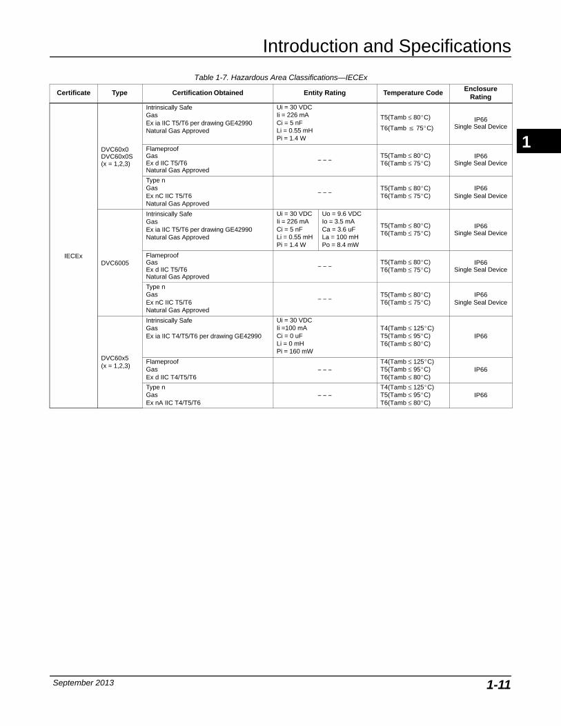
Table 1-7. Hazardous Area Classifications—IECEx
Certificate Type Certification Obtained Entity Rating Temperature Code EnclosureRating
IECEx
DVC60x0DVC60x0S(x = 1,2,3)
Intrinsically SafeGasEx ia IIC T5/T6 per drawing GE42990Natural Gas Approved
Ui = 30 VDCIi = 226 mACi = 5 nFLi = 0.55 mHPi = 1.4 W
T5(Tamb ≤ 80�C)
T6(Tamb � 75�C)IP66
Single Seal Device
FlameproofGasEx d IIC T5/T6Natural Gas Approved
− − −T5(Tamb ≤ 80�C)T6(Tamb ≤ 75�C)
IP66Single Seal Device
Type nGasEx nC IIC T5/T6Natural Gas Approved
− − −T5(Tamb ≤ 80�C)T6(Tamb ≤ 75�C)
IP66Single Seal Device
DVC6005
Intrinsically SafeGasEx ia IIC T5/T6 per drawing GE42990Natural Gas Approved
Ui = 30 VDCIi = 226 mACi = 5 nFLi = 0.55 mHPi = 1.4 W
Uo = 9.6 VDCIo = 3.5 mACa = 3.6 uFLa = 100 mHPo = 8.4 mW
T5(Tamb ≤ 80�C)T6(Tamb ≤ 75�C)
IP66Single Seal Device
FlameproofGasEx d IIC T5/T6Natural Gas Approved
− − −T5(Tamb ≤ 80�C)T6(Tamb ≤ 75�C)
IP66Single Seal Device
Type nGasEx nC IIC T5/T6Natural Gas Approved
− − −T5(Tamb ≤ 80�C)T6(Tamb ≤ 75�C)
IP66Single Seal Device
DVC60x5(x = 1,2,3)
Intrinsically SafeGasEx ia IIC T4/T5/T6 per drawing GE42990
Ui = 30 VDCIi =100 mACi = 0 uFLi = 0 mHPi = 160 mW
T4(Tamb ≤ 125�C)T5(Tamb ≤ 95�C)T6(Tamb ≤ 80�C)
IP66
FlameproofGasEx d IIC T4/T5/T6
− − −T4(Tamb ≤ 125�C)T5(Tamb ≤ 95�C)T6(Tamb ≤ 80�C)
IP66
Type nGasEx nA IIC T4/T5/T6
− − −T4(Tamb ≤ 125�C)T5(Tamb ≤ 95�C)T6(Tamb ≤ 80�C)
IP66
1

DVC6000 SIS
September 20131-12
1

Installation
September 2013 2-1
2-2
Section 2 Installation
Hazardous Area Classifications and Special Instructions for “Safe Use” and Installations in Hazardous Areas
CSA 2-4. . . . . . . . . . . . . . . . . . . . . . . . . . . . . . . . . . . . . . . . . . . . . . . . . . . . . . . . . . . . . . . . . . . . .
FM 2-4. . . . . . . . . . . . . . . . . . . . . . . . . . . . . . . . . . . . . . . . . . . . . . . . . . . . . . . . . . . . . . . . . . . . . .
ATEX 2-4. . . . . . . . . . . . . . . . . . . . . . . . . . . . . . . . . . . . . . . . . . . . . . . . . . . . . . . . . . . . . . . . . . . .
IECEx 2-5. . . . . . . . . . . . . . . . . . . . . . . . . . . . . . . . . . . . . . . . . . . . . . . . . . . . . . . . . . . . . . . . . . .
Mounting Guidelines
DVC6010 SIS on Sliding-Stem Actuators (up to 4 inches travel) 2-6. . . . . . . . . . .
DVC6020 SIS on Long-Stroke Sliding-Stem Actuators(4 to 24 inches travel) and Rotary Actuators 2-8. . . . . . . . . . . . . . . . . . . . . . . . . . . . . .
DVC6030 SIS on Quarter-Turn Actuators 2-10. . . . . . . . . . . . . . . . . . . . . . . . . . . . . . . . .
DVC6005 SIS Base Unit 2-13. . . . . . . . . . . . . . . . . . . . . . . . . . . . . . . . . . . . . . . . . . . . . . . . .Wall Mounting 2-13. . . . . . . . . . . . . . . . . . . . . . . . . . . . . . . . . . . . . . . . . . . . . . . . . . . . . . . . . . .Pipestand Mounting 2-13. . . . . . . . . . . . . . . . . . . . . . . . . . . . . . . . . . . . . . . . . . . . . . . . . . . . . .
DVC6015 on Sliding-Stem Actuators (up to 4 inches travel) 2-13. . . . . . . . . . . . . . . .
DVC6025 on Long-Stroke Sliding-Stem Actuators(4 to 24 inches travel) and Rotary Actuators 2-15. . . . . . . . . . . . . . . . . . . . . . . . . . . . . .
DVC6035 on Quarter-Turn Actuators 2-16. . . . . . . . . . . . . . . . . . . . . . . . . . . . . . . . . . . . .
67CFR Filter RegulatorIntegral-Mounted Regulator 2-17. . . . . . . . . . . . . . . . . . . . . . . . . . . . . . . . . . . . . . . . . . . . . . . .Yoke-Mounted Regulator 2-17. . . . . . . . . . . . . . . . . . . . . . . . . . . . . . . . . . . . . . . . . . . . . . . . . .Casing-Mounted Regulator 2-17. . . . . . . . . . . . . . . . . . . . . . . . . . . . . . . . . . . . . . . . . . . . . . . .
Pneumatic ConnectionsSupply Connections 2-18. . . . . . . . . . . . . . . . . . . . . . . . . . . . . . . . . . . . . . . . . . . . . . . . . . . . .
Output Connections 2-20. . . . . . . . . . . . . . . . . . . . . . . . . . . . . . . . . . . . . . . . . . . . . . . . . . . . . .Single-Acting Actuators 2-20. . . . . . . . . . . . . . . . . . . . . . . . . . . . . . . . . . . . . . . . . . . . . . . . . . .Double-Acting Actuators 2-20. . . . . . . . . . . . . . . . . . . . . . . . . . . . . . . . . . . . . . . . . . . . . . . . . .
Vent 2-22. . . . . . . . . . . . . . . . . . . . . . . . . . . . . . . . . . . . . . . . . . . . . . . . . . . . . . . . . . . . . . . . . . . . .
Electrical Connections
4-20 mA Loop Connections 2-23. . . . . . . . . . . . . . . . . . . . . . . . . . . . . . . . . . . . . . . . . . . . . .
Remote Travel Sensor Connections 2-24. . . . . . . . . . . . . . . . . . . . . . . . . . . . . . . . . . . . . .
Test Connections 2-28. . . . . . . . . . . . . . . . . . . . . . . . . . . . . . . . . . . . . . . . . . . . . . . . . . . . . . . .
Communication Connections 2-28. . . . . . . . . . . . . . . . . . . . . . . . . . . . . . . . . . . . . . . . . . . . .
2
DVC6000 SIS
September 20132-2
Wiring Practices
Logic Solver or Control System Requirements 2-28. . . . . . . . . . . . . . . . . . . . . . . . . . . .Voltage Available 2-28. . . . . . . . . . . . . . . . . . . . . . . . . . . . . . . . . . . . . . . . . . . . . . . . . . . . . . . .Compliance Voltage 2-29. . . . . . . . . . . . . . . . . . . . . . . . . . . . . . . . . . . . . . . . . . . . . . . . . . . . . .
Maximum Cable Capacitance 2-29. . . . . . . . . . . . . . . . . . . . . . . . . . . . . . . . . . . . . . . . . . . .
Installation in a Safety Instrumented System 2-31. . . . . . . . . . . . . . . . . . . . . . . . .
Installation in a 4-Wire System 2-31. . . . . . . . . . . . . . . . . . . . . . . . . . . . . . . . . . . . . . . . . . .
Installation in a 2-Wire System 2-32. . . . . . . . . . . . . . . . . . . . . . . . . . . . . . . . . . . . . . . . . . .
LCP100 (Local Control Panel) 2-35. . . . . . . . . . . . . . . . . . . . . . . . . . . . . . . . . . . . . . . . . . .Installation 2-35. . . . . . . . . . . . . . . . . . . . . . . . . . . . . . . . . . . . . . . . . . . . . . . . . . . . . . . . . . . . .Electrical Connections 2-35. . . . . . . . . . . . . . . . . . . . . . . . . . . . . . . . . . . . . . . . . . . . . . . . . . . .
2

Installation
September 2013 2-3
InstallationThe DVC6000 SIS can be used with either air ornatural gas as the supply medium. If using natural gasas the pneumatic supply medium, natural gas will beused in the pneumatic output connections of theDVC6000 SIS to any connected equipment. In normaloperation the unit will vent the supply medium into thesurrounding atmosphere unless it is remotely vented.
When using natural gas as the supply medium, in anon-hazardous location in a confined area, remoteventing of the unit is required. Failure to do so couldresult in personal injury, property damage, and areare-classification. For hazardous locations remoteventing of the unit may be required, depending uponthe area classification, and as specified by therequirements of local, regional, and national codes,rules and regulations. Failure to do so when necessarycould result in personal injury, property damage, andarea re-classification.
WARNING
Avoid personal injury or propertydamage from sudden release ofprocess pressure or bursting of parts.Before proceeding with anyInstallation procedures:
� Always wear protective clothing,gloves, and eyewear.
� Personal injury or propertydamage may result from fire orexplosion if natural gas is used as thesupply medium and appropriatepreventive measures are not taken.Preventive measures may include, butare not limited to, one or more of thefollowing: Remote venting of the unit,re-evaluating the hazardous areaclassification, ensuring adequateventilation, and the removal of anyignition sources. For information onremote venting of this controller, referto page 2-22.
� If installing this into an existingapplication, also refer to theWARNING at the beginning of theMaintenance section of thisinstruction manual.
� Check with your process orsafety engineer for any additionalmeasures that must be taken toprotect against process media.
WARNING
To avoid static discharge from thecover when flammable gases or dustare present, do not rub or clean thecover with solvents. To do so couldresult in a spark that may cause theflammable gases or dust to explode,resulting in personal injury orproperty damage. Clean with a milddetergent and water only.
WARNING
This unit vents the supply mediuminto the surrounding atmosphere.When installing this unit in anon-hazardous (non-classified)location in a confined area, withnatural gas as the supply medium,you must remotely vent this unit to asafe location. Failure to do so couldresult in personal injury or propertydamage from fire or explosion, andarea re-classification.
When installing this unit in ahazardous (classified) location remoteventing of the unit may be required,depending upon the areaclassification, and as specified by therequirements of local, regional, andnational codes, rules and regulations.Failure to do so when necessarycould result in personal injury orproperty damage from fire orexplosion, and area re-classification.
Vent line piping should comply withlocal and regional codes and shouldbe as short as possible with adequateinside diameter and few bends toreduce case pressure buildup.
2
DVC6000 SIS
September 20132-4
In addition to remote venting of theunit, ensure that all caps and coversare correctly installed. Failure to doso could result in personal injury orproperty damage from fire orexplosion, and area re-classification.
Hazardous Area Classifications andSpecial Instructions for “Safe Use” andInstallations in Hazardous LocationsCertain nameplates may carry more than oneapproval, and each approval may have uniqueinstallation/wiring requirements and/or conditions of“safe use”. These special instructions for “safe use”are in addition to, and may override, the standardinstallation procedures. Special instructions are listedby approval.
NoteThis information supplements thenameplate markings affixed to theproduct.
Always refer to the nameplate itself toidentify the appropriate certification.Contact your Emerson ProcessManagement sales office forapproval/certification information notlisted here.
Approval information is for bothaluminum and stainless steelconstructions.
WARNING
Failure to follow these conditions ofsafe use could result in personalinjury or property damage from fire orexplosion, or area re-classification.
CSAIntrinsic Safety, Explosion proof, Division 2,Dust-Ignition proof
No special conditions for safe use.
Refer to table 1-4 for approval information, figure B-1,B-3 and B-4 for CSA loop schematics, and figure B-2and B-5 for typical CSA nameplates.
FMSpecial Conditions of Safe Use
Intrinsic Safety, Explosion proof, Non-incendive,Dust-Ignition proof
1. When product is used with natural gas as thepneumatic medium, the maximum working pressure ofthe natural gas supply shall be limited to 145 psi.
2. When product is used with natural gas as thepneumatic medium the product shall not be permittedin a Class I, Division 2, Group A, B, C, D locationwithout the proper venting installation as per themanufacturer’s instruction manual.
3. The apparatus enclosure contains aluminum and isconsidered to constitute a potential risk of ignition byimpact or friction. Care must be taken into accountduring installation and use to prevent impact or friction.
4. Parts of the enclosure are constructed from plastic.To prevent risk of electrostatic sparking, the plasticsurface should only be cleaned with a damp cloth.
Refer to table 1-5 for approval information, figure B-6,B-7 and B-8 for FM loop schematics, and figure B-2and B-9 for typical FM nameplates.
ATEXSpecial Conditions for Safe Use
Intrinsically Safe
1. This apparatus can only be connected to anintrinsically safe certified equipment and thiscombination must be compatible as regards theintrinsically safe rules.
2. The electrical parameters of this equipment mustnot exceed any following values:Uo ≤ 30 V; Io ≤ 226 mA; Po ≤ 1.4 W
3. Operating ambient temperature: −52�C or −40�Cto + 80�C
4. For the model with aluminum body: the apparatusmust not be submitted to frictions or mechanicalimpacts.
5. Covered by standards EN 60079-0 (2009), EN 60079-11 (2012), EN 60079-26 (2007).
6. Install per drawing GE60771.
Refer to table 1-6 for additional approval information,figures B-10, B-12, andB-13 for ATEX loop schematicsand figure B-11 for typical ATEX Intrinsic Safetynameplates.
2
Installation
September 2013 2-5
Flameproof
Operating ambient temperature: −52�C or −40�C to + 85�C
Refer to table 1-6 for additional approval information,and figure B-14 for typical ATEX Flameproofnameplates.
Type n
Operating ambient temperature: −52�C or −40�C to + 80�C
Refer to table 1-6 for additional approval information,and figure B-15 for typical ATEX Type n nameplates.
IECExConditions of Certification
Intrinsically Safe, Type n, Flameproof
Ex ia / Ex nC / Ex d
1. Warning: Electrostatic charge hazard. Do not rubor clean with solvents. To do so could result in anexplosion.
Ex nC / Ex nA / Ex d
2. Do not open while energized.
Refer to table 1-7 for additional approval information,and figures B-16, B-17, and B-18 for IECEx loopschematics, and figures B-19 and B-20 for typicalIECEx nameplates.
2
DVC6000 SIS
September 20132-6
/ OC
CAP SCREW, FLANGED
MACHINE SCREW
SHIELD
ADJUSTMENT ARM
CONNECTOR ARMCAP SCREW
PLAIN WASHER
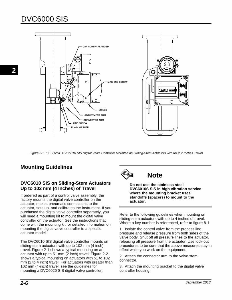
Figure 2-1. FIELDVUE DVC6010 SIS Digital Valve Controller Mounted on Sliding-Stem Actuators with up to 2 Inches Travel
Mounting Guidelines
DVC6010 SIS on Sliding-Stem ActuatorsUp to 102 mm (4 Inches) of Travel If ordered as part of a control valve assembly, thefactory mounts the digital valve controller on theactuator, makes pneumatic connections to theactuator, sets up, and calibrates the instrument. If youpurchased the digital valve controller separately, youwill need a mounting kit to mount the digital valvecontroller on the actuator. See the instructions thatcome with the mounting kit for detailed information onmounting the digital valve controller to a specificactuator model.
The DVC6010 SIS digital valve controller mounts onsliding-stem actuators with up to 102 mm (4 inch)travel. Figure 2-1 shows a typical mounting on anactuator with up to 51 mm (2 inch) travel. Figure 2-2shows a typical mounting on actuators with 51 to 102mm (2 to 4 inch) travel. For actuators with greater than102 mm (4-inch) travel, see the guidelines formounting a DVC6020 SIS digital valve controller.
NoteDo not use the stainless steelDVC6010S SIS in high vibration servicewhere the mounting bracket usesstandoffs (spacers) to mount to theactuator.
Refer to the following guidelines when mounting onsliding-stem actuators with up to 4 inches of travel.Where a key number is referenced, refer to figure 8-1.
1. Isolate the control valve from the process linepressure and release pressure from both sides of thevalve body. Shut off all pressure lines to the actuator,releasing all pressure from the actuator. Use lock-outprocedures to be sure that the above measures stay ineffect while you work on the equipment.
2. Attach the connector arm to the valve stemconnector.
3. Attach the mounting bracket to the digital valvecontroller housing.
2
Installation
September 2013 2-7
CAP SCREW, FLANGED
MACHINE SCREW,FLAT HEAD
SHIELD
ADJUSTMENT ARM
CONNECTOR ARM
PLAIN WASHER
MACHINE SCREW
MACHINE SCREW,LOCK WASHER,HEX NUT
LOCK WASHER
LOCK WASHER
HEX NUT
SPACER
HEX NUT, FLANGED
FEEDBACK ARM EXTENSION,BIAS SPRING
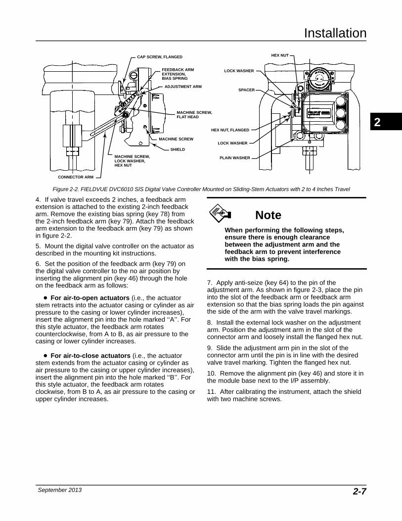
Figure 2-2. FIELDVUE DVC6010 SIS Digital Valve Controller Mounted on Sliding-Stem Actuators with 2 to 4 Inches Travel
4. If valve travel exceeds 2 inches, a feedback armextension is attached to the existing 2-inch feedbackarm. Remove the existing bias spring (key 78) fromthe 2-inch feedback arm (key 79). Attach the feedbackarm extension to the feedback arm (key 79) as shownin figure 2-2.
5. Mount the digital valve controller on the actuator asdescribed in the mounting kit instructions.
6. Set the position of the feedback arm (key 79) onthe digital valve controller to the no air position byinserting the alignment pin (key 46) through the holeon the feedback arm as follows:
� For air-to-open actuators (i.e., the actuatorstem retracts into the actuator casing or cylinder as airpressure to the casing or lower cylinder increases),insert the alignment pin into the hole marked ‘‘A’’. Forthis style actuator, the feedback arm rotatescounterclockwise, from A to B, as air pressure to thecasing or lower cylinder increases.
� For air-to-close actuators (i.e., the actuatorstem extends from the actuator casing or cylinder asair pressure to the casing or upper cylinder increases),insert the alignment pin into the hole marked ‘‘B’’. Forthis style actuator, the feedback arm rotatesclockwise, from B to A, as air pressure to the casing orupper cylinder increases.
NoteWhen performing the following steps,ensure there is enough clearancebetween the adjustment arm and thefeedback arm to prevent interferencewith the bias spring.
7. Apply anti-seize (key 64) to the pin of theadjustment arm. As shown in figure 2-3, place the pininto the slot of the feedback arm or feedback armextension so that the bias spring loads the pin againstthe side of the arm with the valve travel markings.
8. Install the external lock washer on the adjustmentarm. Position the adjustment arm in the slot of theconnector arm and loosely install the flanged hex nut.
9. Slide the adjustment arm pin in the slot of theconnector arm until the pin is in line with the desiredvalve travel marking. Tighten the flanged hex nut.
10. Remove the alignment pin (key 46) and store it inthe module base next to the I/P assembly.
11. After calibrating the instrument, attach the shieldwith two machine screws.
2
DVC6000 SIS
September 20132-8
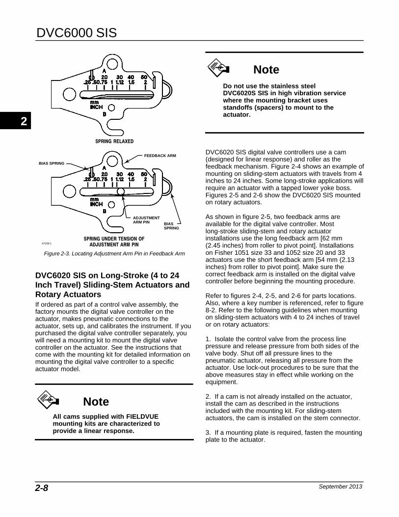
A7209-1
SPRING RELAXED
SPRING UNDER TENSION OFADJUSTMENT ARM PIN
FEEDBACK ARM
ADJUSTMENTARM PIN BIAS
SPRING
BIAS SPRING
Figure 2-3. Locating Adjustment Arm Pin in Feedback Arm
DVC6020 SIS on Long-Stroke (4 to 24Inch Travel) Sliding-Stem Actuators andRotary Actuators If ordered as part of a control valve assembly, thefactory mounts the digital valve controller on theactuator, makes pneumatic connections to theactuator, sets up, and calibrates the instrument. If youpurchased the digital valve controller separately, youwill need a mounting kit to mount the digital valvecontroller on the actuator. See the instructions thatcome with the mounting kit for detailed information onmounting the digital valve controller to a specificactuator model.
NoteAll cams supplied with FIELDVUEmounting kits are characterized toprovide a linear response.
NoteDo not use the stainless steelDVC6020S SIS in high vibration servicewhere the mounting bracket usesstandoffs (spacers) to mount to theactuator.
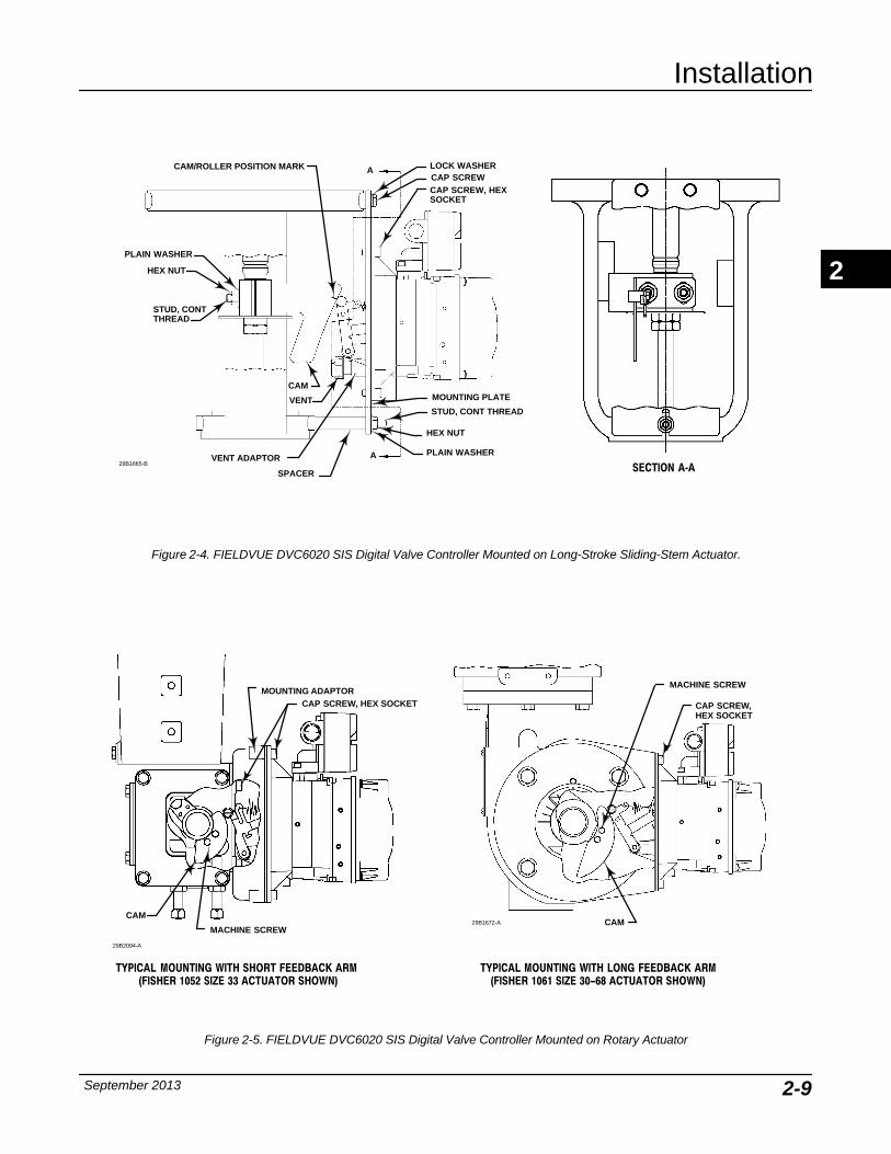
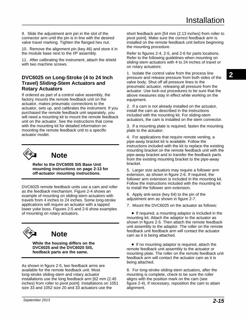
DVC6020 SIS digital valve controllers use a cam(designed for linear response) and roller as thefeedback mechanism. Figure 2-4 shows an example ofmounting on sliding-stem actuators with travels from 4inches to 24 inches. Some long-stroke applications willrequire an actuator with a tapped lower yoke boss.Figures 2-5 and 2-6 show the DVC6020 SIS mountedon rotary actuators.
As shown in figure 2-5, two feedback arms areavailable for the digital valve controller. Mostlong-stroke sliding-stem and rotary actuatorinstallations use the long feedback arm [62 mm (2.45 inches) from roller to pivot point]. Installations on Fisher 1051 size 33 and 1052 size 20 and 33actuators use the short feedback arm [54 mm (2.13inches) from roller to pivot point]. Make sure thecorrect feedback arm is installed on the digital valvecontroller before beginning the mounting procedure.
Refer to figures 2-4, 2-5, and 2-6 for parts locations.Also, where a key number is referenced, refer to figure8-2. Refer to the following guidelines when mountingon sliding-stem actuators with 4 to 24 inches of travelor on rotary actuators:
1. Isolate the control valve from the process linepressure and release pressure from both sides of thevalve body. Shut off all pressure lines to thepneumatic actuator, releasing all pressure from theactuator. Use lock-out procedures to be sure that theabove measures stay in effect while working on theequipment.
2. If a cam is not already installed on the actuator,install the cam as described in the instructionsincluded with the mounting kit. For sliding-stemactuators, the cam is installed on the stem connector.
3. If a mounting plate is required, fasten the mountingplate to the actuator.
2
Installation
September 2013 2-9
PLAIN WASHER
HEX NUT
STUD, CONT THREAD
A LOCK WASHERCAP SCREW
MOUNTING PLATE
CAP SCREW, HEXSOCKET
VENT
PLAIN WASHER
HEX NUT
STUD, CONT THREAD
A
SPACER SECTION A‐A
CAM
CAM/ROLLER POSITION MARK
29B1665-BVENT ADAPTOR
Figure 2-4. FIELDVUE DVC6020 SIS Digital Valve Controller Mounted on Long-Stroke Sliding-Stem Actuator.
TYPICAL MOUNTING WITH SHORT FEEDBACK ARM (FISHER 1052 SIZE 33 ACTUATOR SHOWN)
TYPICAL MOUNTING WITH LONG FEEDBACK ARM(FISHER 1061 SIZE 30-68 ACTUATOR SHOWN)
29B2094-A
29B1672-A
MOUNTING ADAPTORCAP SCREW, HEX SOCKET
CAM
MACHINE SCREW
MACHINE SCREW
CAP SCREW, HEX SOCKET
CAM
Figure 2-5. FIELDVUE DVC6020 SIS Digital Valve Controller Mounted on Rotary Actuator
2
DVC6000 SIS
September 20132-10
CAP SCREW, HEX SOCKET
CAM
FOLLOWER ARMEXTENSION
MACHINE SCREW,LOCK WASHER,HEX NUT
CAP SCREW
29B1673-A
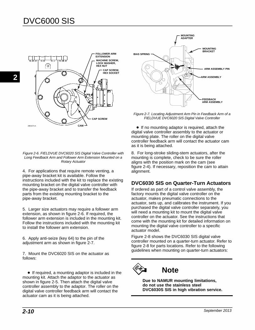
Figure 2-6. FIELDVUE DVC6020 SIS Digital Valve Controller withLong Feedback Arm and Follower Arm Extension Mounted on a
Rotary Actuator
4. For applications that require remote venting, apipe-away bracket kit is available. Follow theinstructions included with the kit to replace the existingmounting bracket on the digital valve controller withthe pipe-away bracket and to transfer the feedbackparts from the existing mounting bracket to thepipe-away bracket.
5. Larger size actuators may require a follower armextension, as shown in figure 2-6. If required, thefollower arm extension is included in the mounting kit.Follow the instructions included with the mounting kitto install the follower arm extension.
6. Apply anti-seize (key 64) to the pin of theadjustment arm as shown in figure 2-7.
7. Mount the DVC6020 SIS on the actuator asfollows:
� If required, a mounting adaptor is included in themounting kit. Attach the adaptor to the actuator asshown in figure 2-5. Then attach the digital valvecontroller assembly to the adaptor. The roller on thedigital valve controller feedback arm will contact theactuator cam as it is being attached.
MOUNTINGADAPTER
FEEDBACKARM ASSEMBLY
BIAS SPRING
ARM ASSEMBLY PIN
ARM ASSEMBLY
MOUNTING BRACKET
Figure 2-7. Locating Adjustment Arm Pin in Feedback Arm of aFIELDVUE DVC6020 SIS Digital Valve Controller
� If no mounting adaptor is required, attach thedigital valve controller assembly to the actuator ormounting plate. The roller on the digital valvecontroller feedback arm will contact the actuator camas it is being attached.
8. For long-stroke sliding-stem actuators, after themounting is complete, check to be sure the rolleraligns with the position mark on the cam (see figure 2-4). If necessary, reposition the cam to attainalignment.
DVC6030 SIS on Quarter-Turn Actuators If ordered as part of a control valve assembly, thefactory mounts the digital valve controller on theactuator, makes pneumatic connections to theactuator, sets up, and calibrates the instrument. If youpurchased the digital valve controller separately, youwill need a mounting kit to mount the digital valvecontroller on the actuator. See the instructions thatcome with the mounting kit for detailed information onmounting the digital valve controller to a specificactuator model.
Figure 2-8 shows the DVC6030 SIS digital valvecontroller mounted on a quarter-turn actuator. Refer tofigure 2-8 for parts locations. Refer to the followingguidelines when mounting on quarter-turn actuators:
NoteDue to NAMUR mounting limitations,do not use the stainless steelDVC6030S SIS in high vibration service.
2

Installation
September 2013 2-11
19B3879−A
MOUNTING BRACKET
TRAVEL INDICATOR
TRAVELINDICATOR PIN
FEEDBACK ARM
SPACER29B1703-A
Figure 2-8. Mounting a FIELDVUE DVC6030 SIS Digital Valve Controller on a Rotary Actuator (1032 Size 425A Shown)
1. Isolate the control valve from the process linepressure and release pressure from both sides of thevalve body. Shut off all pressure lines to the pneumaticactuator, releasing all pressure from the actuator. Uselock-out procedures to be sure that the abovemeasures stay in effect while working on theequipment.
2. If necessary, remove the existing hub from theactuator shaft.
3. If a positioner plate is required, attach thepositioner plate to the actuator as described in themounting kit instructions.
4. If required, attach the spacer to the actuator shaft.
Refer to figures 2-9 and 2-10. The travel indicatorassembly can have a starting position of 7:30 or10:30. Determine the desired starting position thenproceed with the next step. Considering the top of thedigital valve controller as the 12 o’clock position, in thenext step attach the travel indicator, so that the pin ispositioned as follows:
� If increasing pressure from the digital valvecontroller output A rotates the potentiometer shaftclockwise (as viewed from the back of theinstrument), mount the travel indicator assembly suchthat the arrow is in the 10:30 position, as shown infigure 2-9.
� If increasing pressure from the digital valvecontroller output A rotates the potentiometer shaft
counterclockwise (as viewed from the back of theinstrument), mount the travel indicator assembly suchthat the arrow is in the 7:30 position, as shown infigure 2-10.
Note
ValveLink software and the FieldCommunicator use the convention ofclockwise (figure 2-9) andcounterclockwise (figure 2-10) whenviewing the potentiometer shaft fromthe back of the FIELDVUE instrument.
5. Attach the travel indicator, to the shaft connector orspacer as described in the mounting kit instructions.
6. Attach the mounting bracket to the digital valvecontroller.
7. Position the digital valve controller so that the pinon the travel indicator engages the slot in the feedbackarm and the bias spring loads the pin as shown infigure 2-11. Attach the digital valve controller to theactuator or positioner plate.
8. If a travel indicator scale is included in themounting kit, attach the scale as described in themounting kit instructions.
2
DVC6000 SIS
September 20132-12
19B3879-A
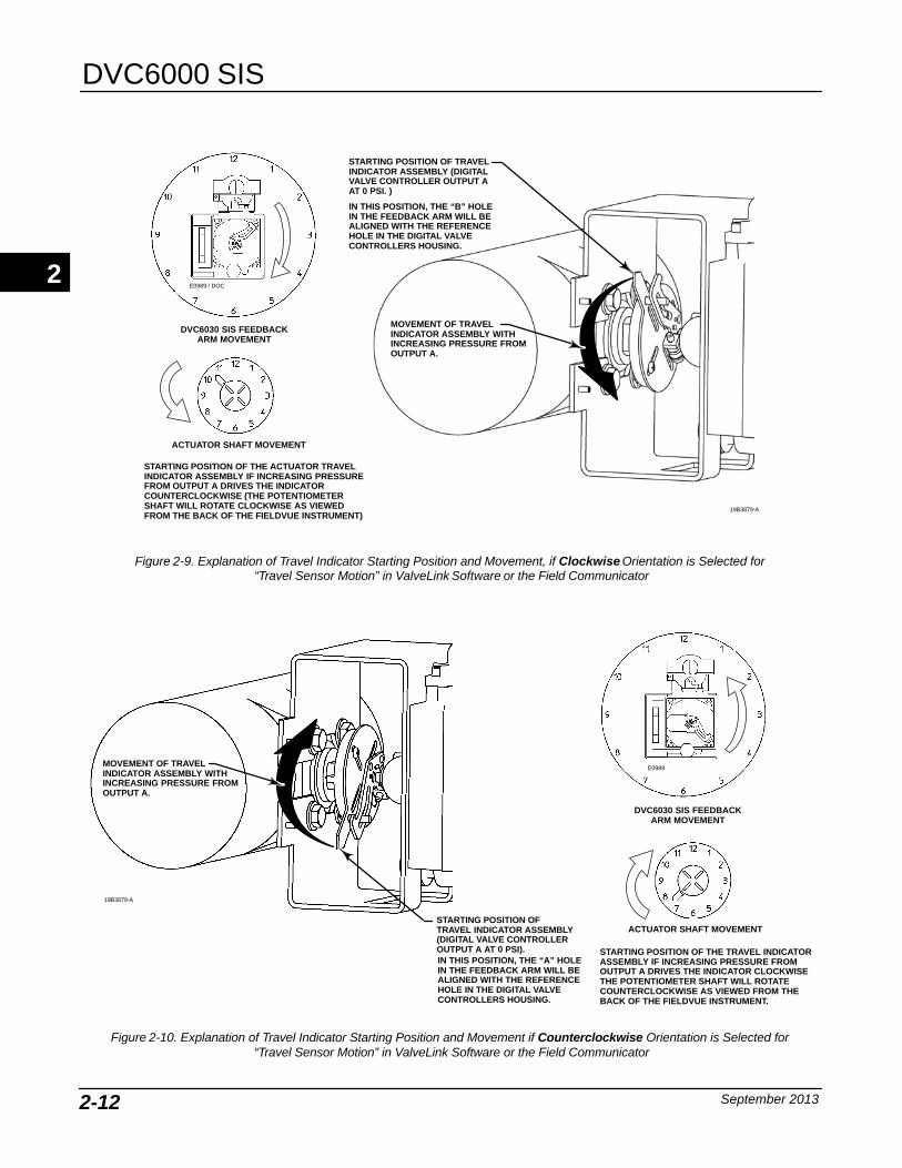
STARTING POSITION OF THE ACTUATOR TRAVELINDICATOR ASSEMBLY IF INCREASING PRESSUREFROM OUTPUT A DRIVES THE INDICATORCOUNTERCLOCKWISE (THE POTENTIOMETERSHAFT WILL ROTATE CLOCKWISE AS VIEWEDFROM THE BACK OF THE FIELDVUE INSTRUMENT)
STARTING POSITION OF TRAVELINDICATOR ASSEMBLY (DIGITALVALVE CONTROLLER OUTPUT A AT 0 PSI. )
IN THIS POSITION, THE “B” HOLEIN THE FEEDBACK ARM WILL BEALIGNED WITH THE REFERENCEHOLE IN THE DIGITAL VALVECONTROLLERS HOUSING.
MOVEMENT OF TRAVELINDICATOR ASSEMBLY WITHINCREASING PRESSURE FROMOUTPUT A.
ACTUATOR SHAFT MOVEMENT
DVC6030 SIS FEEDBACKARM MOVEMENT
E0989 / DOC
Figure 2-9. Explanation of Travel Indicator Starting Position and Movement, if Clockwise Orientation is Selected for “Travel Sensor Motion” in ValveLink Software or the Field Communicator
19B3879-A
STARTING POSITION OF THE TRAVEL INDICATORASSEMBLY IF INCREASING PRESSURE FROMOUTPUT A DRIVES THE INDICATOR CLOCKWISETHE POTENTIOMETER SHAFT WILL ROTATECOUNTERCLOCKWISE AS VIEWED FROM THEBACK OF THE FIELDVUE INSTRUMENT.
STARTING POSITION OFTRAVEL INDICATOR ASSEMBLY(DIGITAL VALVE CONTROLLEROUTPUT A AT 0 PSI).
MOVEMENT OF TRAVELINDICATOR ASSEMBLY WITHINCREASING PRESSURE FROMOUTPUT A.
IN THIS POSITION, THE “A” HOLEIN THE FEEDBACK ARM WILL BEALIGNED WITH THE REFERENCEHOLE IN THE DIGITAL VALVECONTROLLERS HOUSING.
DVC6030 SIS FEEDBACKARM MOVEMENT
ACTUATOR SHAFT MOVEMENT
E0989
Figure 2-10. Explanation of Travel Indicator Starting Position and Movement if Counterclockwise Orientation is Selected for “Travel Sensor Motion” in ValveLink Software or the Field Communicator
2
Installation
September 2013 2-13
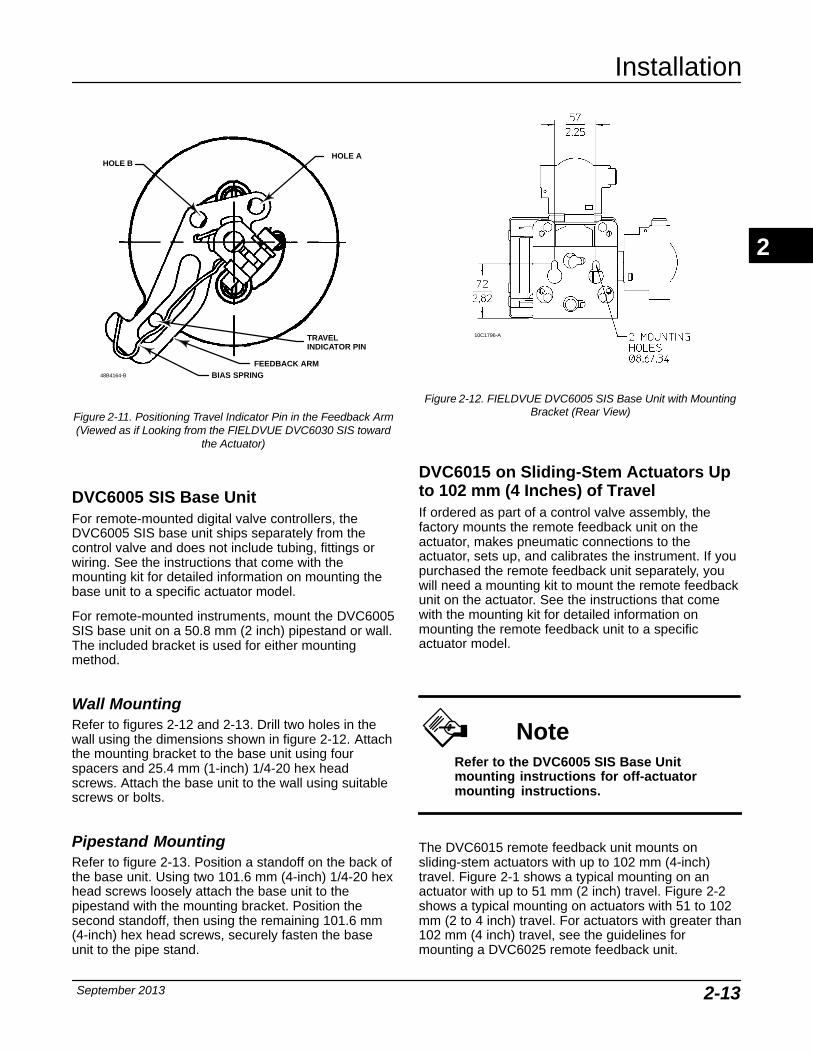
FEEDBACK ARMBIAS SPRING
TRAVEL INDICATOR PIN
48B4164-B
HOLE AHOLE B
Figure 2-11. Positioning Travel Indicator Pin in the Feedback Arm(Viewed as if Looking from the FIELDVUE DVC6030 SIS toward
the Actuator)
DVC6005 SIS Base Unit For remote-mounted digital valve controllers, theDVC6005 SIS base unit ships separately from thecontrol valve and does not include tubing, fittings orwiring. See the instructions that come with themounting kit for detailed information on mounting thebase unit to a specific actuator model.
For remote-mounted instruments, mount the DVC6005SIS base unit on a 50.8 mm (2 inch) pipestand or wall.The included bracket is used for either mountingmethod.
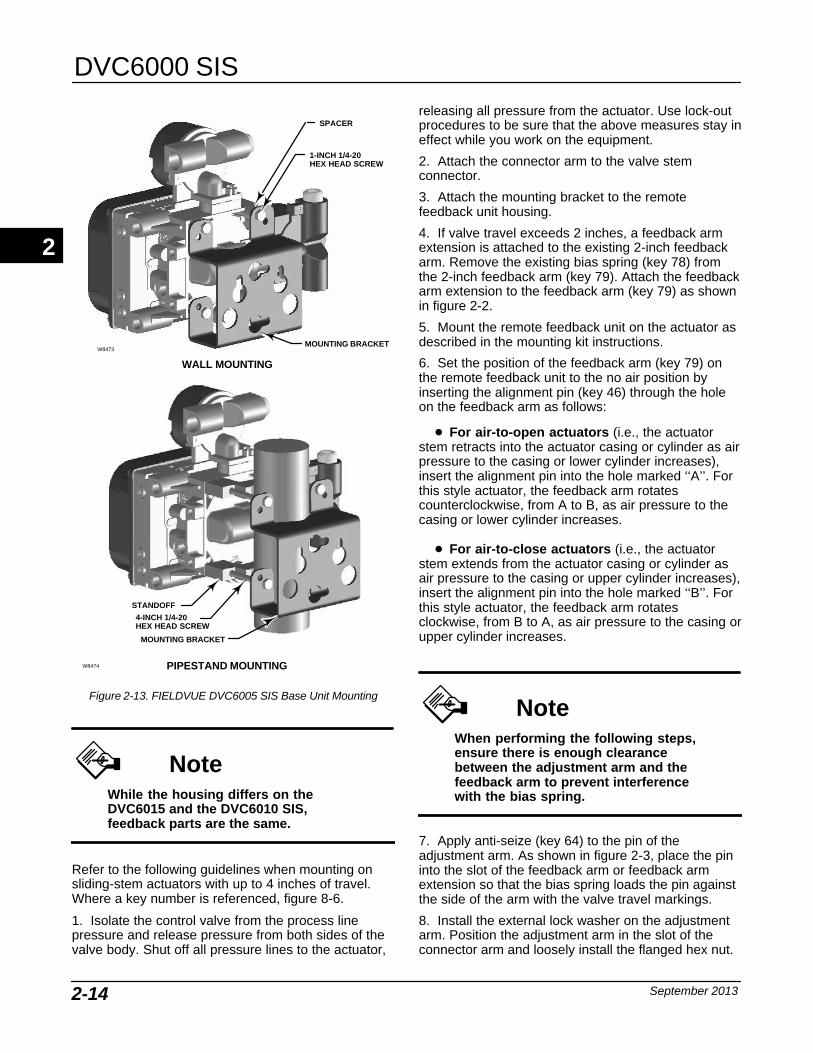
Wall Mounting Refer to figures 2-12 and 2-13. Drill two holes in thewall using the dimensions shown in figure 2-12. Attachthe mounting bracket to the base unit using fourspacers and 25.4 mm (1-inch) 1/4-20 hex headscrews. Attach the base unit to the wall using suitablescrews or bolts.
Pipestand Mounting Refer to figure 2-13. Position a standoff on the back ofthe base unit. Using two 101.6 mm (4-inch) 1/4-20 hexhead screws loosely attach the base unit to thepipestand with the mounting bracket. Position thesecond standoff, then using the remaining 101.6 mm(4-inch) hex head screws, securely fasten the baseunit to the pipe stand.
10C1796-A
Figure 2-12. FIELDVUE DVC6005 SIS Base Unit with MountingBracket (Rear View)
DVC6015 on Sliding-Stem Actuators Upto 102 mm (4 Inches) of Travel If ordered as part of a control valve assembly, thefactory mounts the remote feedback unit on theactuator, makes pneumatic connections to theactuator, sets up, and calibrates the instrument. If youpurchased the remote feedback unit separately, youwill need a mounting kit to mount the remote feedbackunit on the actuator. See the instructions that comewith the mounting kit for detailed information onmounting the remote feedback unit to a specificactuator model.
NoteRefer to the DVC6005 SIS Base Unitmounting instructions for off-actuatormounting instructions.
The DVC6015 remote feedback unit mounts onsliding-stem actuators with up to 102 mm (4-inch)travel. Figure 2-1 shows a typical mounting on anactuator with up to 51 mm (2 inch) travel. Figure 2-2shows a typical mounting on actuators with 51 to 102mm (2 to 4 inch) travel. For actuators with greater than102 mm (4 inch) travel, see the guidelines formounting a DVC6025 remote feedback unit.
2
DVC6000 SIS
September 20132-14
4-INCH 1/4-20 HEX HEAD SCREW
STANDOFF
MOUNTING BRACKET
PIPESTAND MOUNTING
WALL MOUNTING
MOUNTING BRACKET
1-INCH 1/4-20HEX HEAD SCREW
W8473
W8474
SPACER
Figure 2-13. FIELDVUE DVC6005 SIS Base Unit Mounting
NoteWhile the housing differs on theDVC6015 and the DVC6010 SIS,feedback parts are the same.
Refer to the following guidelines when mounting onsliding-stem actuators with up to 4 inches of travel.Where a key number is referenced, figure 8-6.
1. Isolate the control valve from the process linepressure and release pressure from both sides of thevalve body. Shut off all pressure lines to the actuator,
releasing all pressure from the actuator. Use lock-outprocedures to be sure that the above measures stay ineffect while you work on the equipment.
2. Attach the connector arm to the valve stemconnector.
3. Attach the mounting bracket to the remotefeedback unit housing.
4. If valve travel exceeds 2 inches, a feedback armextension is attached to the existing 2-inch feedbackarm. Remove the existing bias spring (key 78) fromthe 2-inch feedback arm (key 79). Attach the feedbackarm extension to the feedback arm (key 79) as shownin figure 2-2.
5. Mount the remote feedback unit on the actuator asdescribed in the mounting kit instructions.
6. Set the position of the feedback arm (key 79) onthe remote feedback unit to the no air position byinserting the alignment pin (key 46) through the holeon the feedback arm as follows:
� For air-to-open actuators (i.e., the actuatorstem retracts into the actuator casing or cylinder as airpressure to the casing or lower cylinder increases),insert the alignment pin into the hole marked ‘‘A’’. Forthis style actuator, the feedback arm rotatescounterclockwise, from A to B, as air pressure to thecasing or lower cylinder increases.
� For air-to-close actuators (i.e., the actuatorstem extends from the actuator casing or cylinder asair pressure to the casing or upper cylinder increases),insert the alignment pin into the hole marked ‘‘B’’. Forthis style actuator, the feedback arm rotatesclockwise, from B to A, as air pressure to the casing orupper cylinder increases.
NoteWhen performing the following steps,ensure there is enough clearancebetween the adjustment arm and thefeedback arm to prevent interferencewith the bias spring.
7. Apply anti-seize (key 64) to the pin of theadjustment arm. As shown in figure 2-3, place the pininto the slot of the feedback arm or feedback armextension so that the bias spring loads the pin againstthe side of the arm with the valve travel markings.
8. Install the external lock washer on the adjustmentarm. Position the adjustment arm in the slot of theconnector arm and loosely install the flanged hex nut.
2
Installation
September 2013 2-15
9. Slide the adjustment arm pin in the slot of theconnector arm until the pin is in line with the desiredvalve travel marking. Tighten the flanged hex nut.
10. Remove the alignment pin (key 46) and store it inthe module base next to the I/P assembly.
11. After calibrating the instrument, attach the shieldwith two machine screws.
DVC6025 on Long-Stroke (4 to 24 InchTravel) Sliding-Stem Actuators andRotary Actuators If ordered as part of a control valve assembly, thefactory mounts the remote feedback unit on theactuator, makes pneumatic connections to theactuator, sets up, and calibrates the instrument. If youpurchased the remote feedback unit separately, youwill need a mounting kit to mount the remote feedbackunit on the actuator. See the instructions that comewith the mounting kit for detailed information onmounting the remote feedback unit to a specificactuator model.
NoteRefer to the DVC6005 SIS Base Unitmounting instructions on page 2-13 foroff-actuator mounting instructions.
DVC6025 remote feedback units use a cam and rolleras the feedback mechanism. Figure 2-4 shows anexample of mounting on sliding-stem actuators withtravels from 4 inches to 24 inches. Some long-strokeapplications will require an actuator with a tappedlower yoke boss. Figures 2-5 and 2-6 show examplesof mounting on rotary actuators.
NoteWhile the housing differs on theDVC6025 and the DVC6020 SIS,feedback parts are the same.
As shown in figure 2-5, two feedback arms areavailable for the remote feedback unit. Mostlong-stroke sliding-stem and rotary actuatorinstallations use the long feedback arm [62 mm (2.45inches) from roller to pivot point]. Installations on 1051size 33 and 1052 size 20 and 33 actuators use the
short feedback arm [54 mm (2.13 inches) from roller topivot point]. Make sure the correct feedback arm isinstalled on the remote feedback unit before beginningthe mounting procedure.
Refer to figures 2-4, 2-5, and 2-6 for parts locations.Refer to the following guidelines when mounting onsliding-stem actuators with 4 to 24 inches of travel oron rotary actuators:
1. Isolate the control valve from the process linepressure and release pressure from both sides of thevalve body. Shut off all pressure lines to thepneumatic actuator, releasing all pressure from theactuator. Use lock-out procedures to be sure that theabove measures stay in effect while working on theequipment.
2. If a cam is not already installed on the actuator,install the cam as described in the instructionsincluded with the mounting kit. For sliding-stemactuators, the cam is installed on the stem connector.
3. If a mounting plate is required, fasten the mountingplate to the actuator.
4. For applications that require remote venting, apipe-away bracket kit is available. Follow theinstructions included with the kit to replace the existingmounting bracket on the remote feedback unit with thepipe-away bracket and to transfer the feedback partsfrom the existing mounting bracket to the pipe-awaybracket.
5. Larger size actuators may require a follower armextension, as shown in figure 2-6. If required, thefollower arm extension is included in the mounting kit.Follow the instructions included with the mounting kitto install the follower arm extension.
6. Apply anti-seize (key 64) to the pin of theadjustment arm as shown in figure 2-7.
7. Mount the DVC6025 on the actuator as follows:
� If required, a mounting adaptor is included in themounting kit. Attach the adaptor to the actuator asshown in figure 2-5. Then attach the remote feedbackunit assembly to the adaptor. The roller on the remotefeedback unit feedback arm will contact the actuatorcam as it is being attached.
� If no mounting adaptor is required, attach theremote feedback unit assembly to the actuator ormounting plate. The roller on the remote feedback unitfeedback arm will contact the actuator cam as it isbeing attached.
8. For long-stroke sliding-stem actuators, after themounting is complete, check to be sure the rolleraligns with the position mark on the cam (see figure 2-4). If necessary, reposition the cam to attainalignment.
2
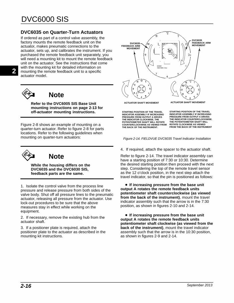
DVC6000 SIS
September 20132-16
DVC6035 on Quarter-Turn Actuators If ordered as part of a control valve assembly, thefactory mounts the remote feedback unit on theactuator, makes pneumatic connections to theactuator, sets up, and calibrates the instrument. If youpurchased the remote feedback unit separately, youwill need a mounting kit to mount the remote feedbackunit on the actuator. See the instructions that comewith the mounting kit for detailed information onmounting the remote feedback unit to a specificactuator model.
NoteRefer to the DVC6005 SIS Base Unitmounting instructions on page 2-13 foroff-actuator mounting instructions.
Figure 2-8 shows an example of mounting on aquarter-turn actuator. Refer to figure 2-8 for partslocations. Refer to the following guidelines whenmounting on quarter-turn actuators:
NoteWhile the housing differs on theDVC6035 and the DVC6030 SIS,feedback parts are the same.
1. Isolate the control valve from the process linepressure and release pressure from both sides of thevalve body. Shut off all pressure lines to the pneumaticactuator, releasing all pressure from the actuator. Uselock-out procedures to be sure that the abovemeasures stay in effect while working on theequipment.
2. If necessary, remove the existing hub from theactuator shaft.
3. If a positioner plate is required, attach thepositioner plate to the actuator as described in themounting kit instructions.
STARTING POSITION OF THE TRAVELINDICATOR ASSEMBLY IF INCREASINGPRESSURE FROM OUTPUT A DRIVES THE INDICATOR CLOCKWISE. THEPOTENTIOMETER SHAFT WILL ROTATECOUNTERCLOCKWISE AS VIEWED FROMTHE BACK OF THE INSTRUMENT.
STARTING POSITION OF THE TRAVELINDICATOR ASSEMBLY IF INCREASINGPRESSURE FROM OUTPUT A DRIVESTHE INDICATOR COUNTERCLOCKWISE.THE POTENTIOMETER SHAFT WILLROTATE CLOCKWISE AS VIEWEDFROM THE BACK OF THE INSTRUMENT
ACTUATOR SHAFT MOVEMENT ACTUATOR SHAFT MOVEMENT
DVC6035FEEDBACK ARM
MOVEMENT
DVC6035FEEDBACK ARMMOVEMENT
E098949B7988 / Doc
Figure 2-14. FIELDVUE DVC6035 Travel Indicator Installation
4. If required, attach the spacer to the actuator shaft.
Refer to figure 2-14. The travel indicator assembly canhave a starting position of 7:30 or 10:30. Determinethe desired starting position then proceed with the nextstep. Considering the top of the remote travel sensoras the 12 o’clock position, in the next step attach thetravel indicator, so that the pin is positioned as follows:
� If increasing pressure from the base unitoutput A rotates the remote feedback unitspotentiometer shaft counterclockwise (as viewedfrom the back of the instrument), mount the travelindicator assembly such that the arrow is in the 7:30position, as shown in figures 2-10 and 2-14.
� If increasing pressure from the base unitoutput A rotates the remote feedback unitspotentiometer shaft clockwise (as viewed from theback of the instrument), mount the travel indicatorassembly such that the arrow is in the 10:30 position,as shown in figures 2-9 and 2-14.
2
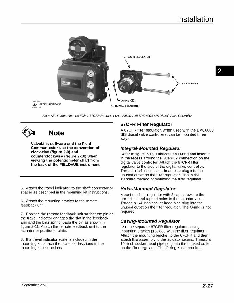
Installation
September 2013 2-17
NOTE:APPLY LUBRICANT1
1
W8077-1 SIS
67CFR REGULATOR
CAP SCREWS
O-RING
SUPPLY CONNECTION
Figure 2-15. Mounting the Fisher 67CFR Regulator on a FIELDVUE DVC6000 SIS Digital Valve Controller
NoteValveLink software and the FieldCommunicator use the convention ofclockwise (figure 2-9) andcounterclockwise (figure 2-10) whenviewing the potentiometer shaft fromthe back of the FIELDVUE instrument.
5. Attach the travel indicator, to the shaft connector orspacer as described in the mounting kit instructions.
6. Attach the mounting bracket to the remotefeedback unit.
7. Position the remote feedback unit so that the pin onthe travel indicator engages the slot in the feedbackarm and the bias spring loads the pin as shown infigure 2-11. Attach the remote feedback unit to theactuator or positioner plate.
8. If a travel indicator scale is included in themounting kit, attach the scale as described in themounting kit instructions.
67CFR Filter Regulator A 67CFR filter regulator, when used with the DVC6000SIS digital valve controllers, can be mounted threeways.
Integral-Mounted RegulatorRefer to figure 2-15. Lubricate an O-ring and insert itin the recess around the SUPPLY connection on thedigital valve controller. Attach the 67CFR filterregulator to the side of the digital valve controller.Thread a 1/4-inch socket-head pipe plug into theunused outlet on the filter regulator. This is thestandard method of mounting the filter regulator.
Yoke-Mounted RegulatorMount the filter regulator with 2 cap screws to thepre-drilled and tapped holes in the actuator yoke.Thread a 1/4-inch socket-head pipe plug into theunused outlet on the filter regulator. The O-ring is notrequired.
Casing-Mounted RegulatorUse the separate 67CFR filter regulator casingmounting bracket provided with the filter regulator.Attach the mounting bracket to the 67CFR and thenattach this assembly to the actuator casing. Thread a1/4-inch socket-head pipe plug into the unused outleton the filter regulator. The O-ring is not required.
2
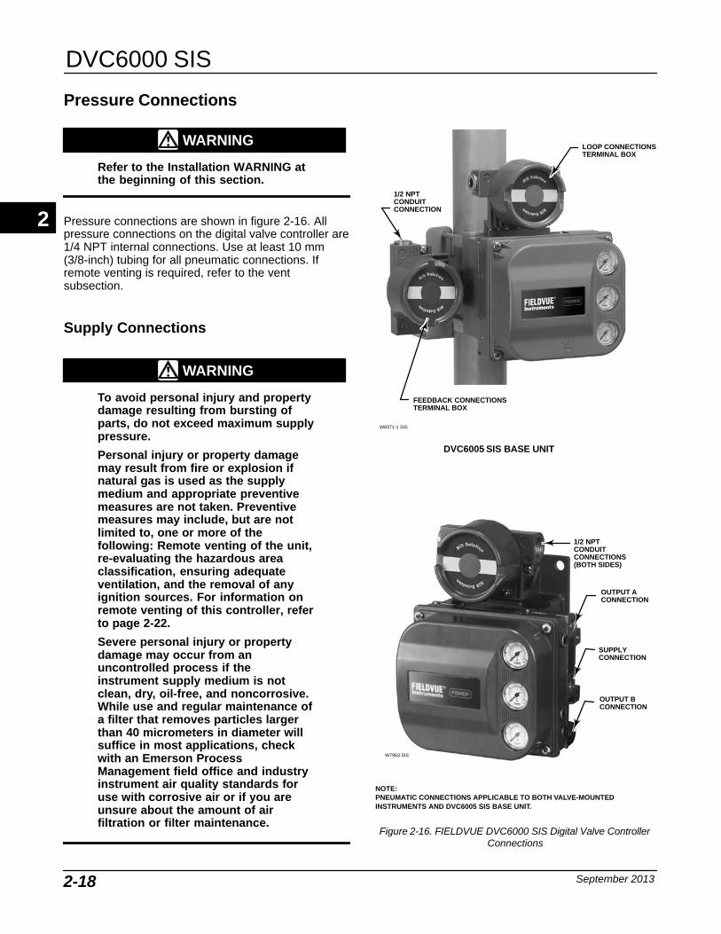
DVC6000 SIS
September 20132-18
Pressure Connections
WARNING
Refer to the Installation WARNING atthe beginning of this section.
Pressure connections are shown in figure 2-16. Allpressure connections on the digital valve controller are1/4 NPT internal connections. Use at least 10 mm(3/8-inch) tubing for all pneumatic connections. Ifremote venting is required, refer to the ventsubsection.
Supply Connections
WARNING
To avoid personal injury and propertydamage resulting from bursting ofparts, do not exceed maximum supplypressure.
Personal injury or property damagemay result from fire or explosion ifnatural gas is used as the supplymedium and appropriate preventivemeasures are not taken. Preventivemeasures may include, but are notlimited to, one or more of thefollowing: Remote venting of the unit,re-evaluating the hazardous areaclassification, ensuring adequateventilation, and the removal of anyignition sources. For information onremote venting of this controller, referto page 2-22.
Severe personal injury or propertydamage may occur from anuncontrolled process if theinstrument supply medium is notclean, dry, oil-free, and noncorrosive.While use and regular maintenance ofa filter that removes particles largerthan 40 micrometers in diameter willsuffice in most applications, checkwith an Emerson ProcessManagement field office and industryinstrument air quality standards foruse with corrosive air or if you areunsure about the amount of airfiltration or filter maintenance.
OUTPUT ACONNECTION
SUPPLYCONNECTION
OUTPUT BCONNECTION
1/2 NPTCONDUITCONNECTIONS(BOTH SIDES)
W7963 SIS
FEEDBACK CONNECTIONSTERMINAL BOX
1/2 NPTCONDUITCONNECTION
DVC6005 SIS BASE UNIT
LOOP CONNECTIONSTERMINAL BOX
W8371-1 SIS
NOTE:PNEUMATIC CONNECTIONS APPLICABLE TO BOTH VALVE-MOUNTEDINSTRUMENTS AND DVC6005 SIS BASE UNIT.
Figure 2-16. FIELDVUE DVC6000 SIS Digital Valve ControllerConnections
2
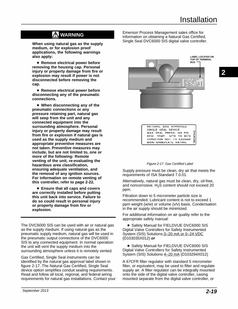
Installation
September 2013 2-19
WARNING
When using natural gas as the supplymedium, or for explosion proofapplications, the following warningsalso apply:
� Remove electrical power beforeremoving the housing cap. Personalinjury or property damage from fire orexplosion may result if power is notdisconnected before removing thecap.
� Remove electrical power beforedisconnecting any of the pneumaticconnections.
� When disconnecting any of thepneumatic connections or anypressure retaining part, natural gaswill seep from the unit and anyconnected equipment into thesurrounding atmosphere. Personalinjury or property damage may resultfrom fire or explosion if natural gas isused as the supply medium andappropriate preventive measures arenot taken. Preventive measures mayinclude, but are not limited to, one ormore of the following: Remoteventing of the unit, re-evaluating thehazardous area classification,ensuring adequate ventilation, andthe removal of any ignition sources.For information on remote venting ofthis controller, refer to page 2-22.
� Ensure that all caps and coversare correctly installed before puttingthis unit back into service. Failure todo so could result in personal injuryor property damage from fire orexplosion.
The DVC6000 SIS can be used with air or natural gasas the supply medium. If using natural gas as thepneumatic supply medium, natural gas will be used inthe pneumatic output connections of the DVC6000SIS to any connected equipment. In normal operationthe unit will vent the supply medium into thesurrounding atmosphere unless it is remotely vented.
Gas Certified, Single Seal instruments can beidentified by the natural gas approval label shown infigure 2-17. The Natural Gas Certified, Single Sealdevice option simplifies conduit sealing requirements.Read and follow all local, regional, and federal wiringrequirements for natural gas installations. Contact your
Emerson Process Management sales office forinformation on obtaining a Natural Gas Certified,Single Seal DVC6000 SIS digital valve controller.
LABEL LOCATED ONTOP OF TERMINALBOX
Figure 2-17. Gas Certified Label
Supply pressure must be clean, dry air that meets therequirements of ISA Standard 7.0.01.
Alternatively, natural gas must be clean, dry, oil-free,and noncorrosive. H2S content should not exceed 20ppm.
Filtration down to 5 micrometer particle size isrecommended. Lubricant content is not to exceed 1ppm weight (w/w) or volume (v/v) basis. Condensationin the air supply should be minimized.
For additional information on air quality refer to theappropriate safety manual:
� Safety Manual for FIELDVUE DVC6000 SISDigital Valve Controllers for Safety InstrumentedSystem (SIS) Solutions 0−20 mA or 0−24 VDC(D103035X012) or
� Safety Manual for FIELDVUE DVC6000 SISDigital Valve Controllers for Safety InstrumentedSystem (SIS) Solutions 4−20 mA (D103294X012)
A 67CFR filter regulator with standard 5 micrometerfilter, or equivalent, may be used to filter and regulatesupply air. A filter regulator can be integrally mountedonto the side of the digital valve controller, casingmounted separate from the digital valve controller, or
2
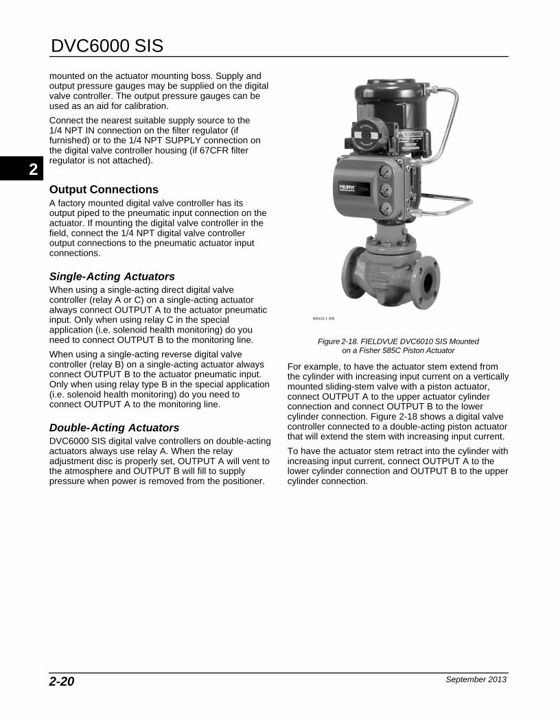
DVC6000 SIS
September 20132-20
mounted on the actuator mounting boss. Supply andoutput pressure gauges may be supplied on the digitalvalve controller. The output pressure gauges can beused as an aid for calibration.
Connect the nearest suitable supply source to the 1/4 NPT IN connection on the filter regulator (iffurnished) or to the 1/4 NPT SUPPLY connection onthe digital valve controller housing (if 67CFR filterregulator is not attached).
Output Connections A factory mounted digital valve controller has itsoutput piped to the pneumatic input connection on theactuator. If mounting the digital valve controller in thefield, connect the 1/4 NPT digital valve controlleroutput connections to the pneumatic actuator inputconnections.
Single-Acting ActuatorsWhen using a single-acting direct digital valvecontroller (relay A or C) on a single-acting actuatoralways connect OUTPUT A to the actuator pneumaticinput. Only when using relay C in the specialapplication (i.e. solenoid health monitoring) do youneed to connect OUTPUT B to the monitoring line.
When using a single-acting reverse digital valvecontroller (relay B) on a single-acting actuator alwaysconnect OUTPUT B to the actuator pneumatic input.Only when using relay type B in the special application(i.e. solenoid health monitoring) do you need toconnect OUTPUT A to the monitoring line.
Double-Acting ActuatorsDVC6000 SIS digital valve controllers on double-actingactuators always use relay A. When the relayadjustment disc is properly set, OUTPUT A will vent tothe atmosphere and OUTPUT B will fill to supplypressure when power is removed from the positioner.
W9131-1 SIS
Figure 2-18. FIELDVUE DVC6010 SIS Mountedon a Fisher 585C Piston Actuator
For example, to have the actuator stem extend fromthe cylinder with increasing input current on a verticallymounted sliding-stem valve with a piston actuator,connect OUTPUT A to the upper actuator cylinderconnection and connect OUTPUT B to the lowercylinder connection. Figure 2-18 shows a digital valvecontroller connected to a double-acting piston actuatorthat will extend the stem with increasing input current.
To have the actuator stem retract into the cylinder withincreasing input current, connect OUTPUT A to thelower cylinder connection and OUTPUT B to the uppercylinder connection.
2

Installation
September 2013 2-21
24/48 VDC 110/220 VAC, etc.
Port A
CONTROL SIGNAL(4−20 mA, 0−20 mA, 0−24 VDC)
Port B
SUPPLY PRESSURE
MONITORING LINE
CONTROL LINE
DVC6000 SIS DIGITAL VALVECONTROLLER WITH RELAY C
SPRING RETURN ACTUATORE1048
Figure 2-19. Pneumatic Hookup for Solenoid Testing
Special Construction to Support LogicSolver Initiated Solenoid Valve HealthMonitoringIn single-acting actuator applications with a solenoidvalve installed, the DVC6000 SIS can be configured tomonitor the health of the solenoid valve test, which isinitiated by the Logic Solver. This is accomplished byconnecting the unused output port B from theDVC6000 SIS to the pneumatic monitoring linebetween the solenoid valve and the actuator, asshown in figure 2-19. When single-acting, direct relayC is installed, the “unused” output port is port B. Whensingle-acting, reverse relay B is used, the unused portis port A.
NoteThis application is called “specialapplication” in the Setup Wizard relayselection.
This configuration is not possible witha double-acting actuator or whenusing relay A in single-acting mode.
2
DVC6000 SIS
September 20132-22
Vent
WARNING
Personal injury or property damagecan occur from cover failure due tooverpressure. Ensure that thehousing vent opening is open andfree of debris to prevent pressurebuildup under the cover.
WARNING
This unit vents the supply mediuminto the surrounding atmosphere.When installing this unit in anon-hazardous (non-classified)location in a confined area, withnatural gas as the supply medium,you must remotely vent this unit to asafe location. Failure to do so couldresult in personal injury or propertydamage from fire or explosion, andarea re-classification.
When installing this unit in ahazardous (classified) location remoteventing of the unit may be required,depending upon the areaclassification, and as specified by therequirements of local, regional, andnational codes, rules and regulations.Failure to do so when necessarycould result in personal injury orproperty damage from fire orexplosion, and area re-classification.
Vent line piping should comply withlocal and regional codes and shouldbe as short as possible with adequateinside diameter and few bends to re-duce case pressure buildup.
In addition to remote venting of theunit, ensure that all caps and coversare correctly installed. Failure to doso could result in personal injury orproperty damage from fire or explo-sion, and area re-classification.
The relay output constantly bleeds supply air into thearea under the cover. The vent opening at the back ofthe housing should be left open to prevent pressurebuildup under the cover. If a remote vent is required,
the vent line must be as short as possible with aminimum number of bends and elbows.
To connect a remote vent to DVC6010 SIS andDVC6030 SIS digital valve controllers andDVC6005 SIS base unit— remove the plastic vent(key 52, figure 8-1). The vent connection is 3/8 NPTinternal. At a minimum, 12.7 mm (1/2-inch) tubingshould be used when installing a remote vent toprevent excessive pressure from building up under thecover.
To connect a remote vent to DVC6020 SIS digitalvalve controllers— Replace the standard mountingbracket (key 74, figure 8-2) with the vent-away bracket(key 74). Install a pipe plug in the vent-away mountingbracket (key 74). Mount the digital valve controller onthe actuator as described in the Installation section ofthis manual. The vent connection is 3/8 NPT internal.At a minimum, 12.7 mm (1/2-inch) tubing should beused when installing a remote vent to preventexcessive pressure from building up under the cover.
Electrical Connections
WARNING
To avoid personal injury resultingfrom electrical shock, do not exceedthe maximum input voltage specifiedin table 1-2 of this instruction manual,or on the product nameplate. If theinput voltage specified differs, do notexceed the lowest specified maximuminput voltage.
Personal injury or property damagecaused by fire or explosion may occurif this connection is attempted in apotentially explosive atmosphere or inan area that has been classified ashazardous. Confirm that areaclassification and atmosphereconditions permit the safe removal ofthe terminal box cover beforeproceeding.
Select wiring and/or cable glands thatare rated for the environment of use(such as hazardous area, ingressprotection and temperature). Failureto use properly rated wiring and/orcable glands can result in personalinjury or property damage from fire orexplosion.
2
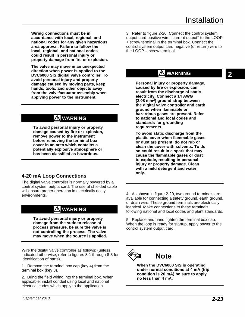
Installation
September 2013 2-23
Wiring connections must be inaccordance with local, regional, andnational codes for any given hazardousarea approval. Failure to follow thelocal, regional, and national codescould result in personal injury orproperty damage from fire or explosion.
The valve may move in an unexpecteddirection when power is applied to theDVC6000 SIS digital valve controller. Toavoid personal injury and propertydamage caused by moving parts, keephands, tools, and other objects awayfrom the valve/actuator assembly whenapplying power to the instrument.
WARNING
To avoid personal injury or propertydamage caused by fire or explosion,remove power to the instrumentbefore removing the terminal boxcover in an area which contains apotentially explosive atmosphere orhas been classified as hazardous.
4-20 mA Loop Connections The digital valve controller is normally powered by acontrol system output card. The use of shielded cablewill ensure proper operation in electrically noisyenvironments.
WARNING
To avoid personal injury or propertydamage from the sudden release ofprocess pressure, be sure the valve isnot controlling the process. The valvemay move when the source is applied.
Wire the digital valve controller as follows: (unlessindicated otherwise, refer to figures 8-1 through 8-3 foridentification of parts).
1. Remove the terminal box cap (key 4) from theterminal box (key 3).
2. Bring the field wiring into the terminal box. Whenapplicable, install conduit using local and nationalelectrical codes which apply to the application.
3. Refer to figure 2-20. Connect the control systemoutput card positive wire ‘‘current output’’ to the LOOP+ screw terminal in the terminal box. Connect thecontrol system output card negative (or return) wire tothe LOOP − screw terminal.
WARNING
Personal injury or property damage,caused by fire or explosion, canresult from the discharge of staticelectricity. Connect a 14 AWG (2.08 mm2) ground strap betweenthe digital valve controller and earthground when flammable orhazardous gases are present. Referto national and local codes andstandards for groundingrequirements.
To avoid static discharge from theplastic cover when flammable gasesor dust are present, do not rub orclean the cover with solvents. To doso could result in a spark that maycause the flammable gases or dustto explode, resulting in personalinjury or property damage. Cleanwith a mild detergent and wateronly.
4. As shown in figure 2-20, two ground terminals areavailable for connecting a safety ground, earth ground,or drain wire. These ground terminals are electricallyidentical. Make connections to these terminalsfollowing national and local codes and plant standards.
5. Replace and hand tighten the terminal box cap.When the loop is ready for startup, apply power to thecontrol system output card.
NoteWhen the DVC6000 SIS is operatingunder normal conditions at 4 mA (tripcondition is 20 mA) be sure to applyno less than 4 mA.
2
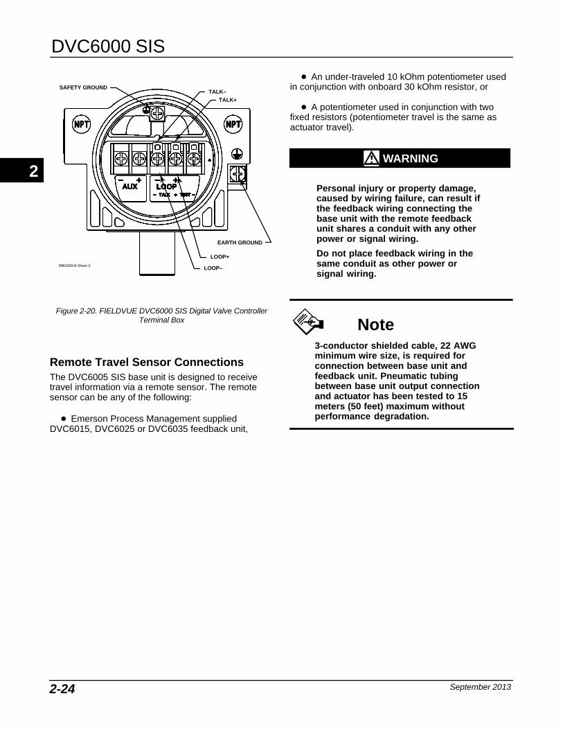
DVC6000 SIS
September 20132-24
SAFETY GROUND
LOOP−
LOOP+
EARTH GROUND
TALK+TALK−
39B3399-B Sheet 2
Figure 2-20. FIELDVUE DVC6000 SIS Digital Valve ControllerTerminal Box
Remote Travel Sensor Connections The DVC6005 SIS base unit is designed to receivetravel information via a remote sensor. The remotesensor can be any of the following:
� Emerson Process Management suppliedDVC6015, DVC6025 or DVC6035 feedback unit,
� An under-traveled 10 kOhm potentiometer usedin conjunction with onboard 30 kOhm resistor, or
� A potentiometer used in conjunction with twofixed resistors (potentiometer travel is the same asactuator travel).
WARNING
Personal injury or property damage,caused by wiring failure, can result ifthe feedback wiring connecting thebase unit with the remote feedbackunit shares a conduit with any otherpower or signal wiring.
Do not place feedback wiring in thesame conduit as other power orsignal wiring.
Note3-conductor shielded cable, 22 AWGminimum wire size, is required forconnection between base unit andfeedback unit. Pneumatic tubingbetween base unit output connectionand actuator has been tested to 15meters (50 feet) maximum withoutperformance degradation.
2
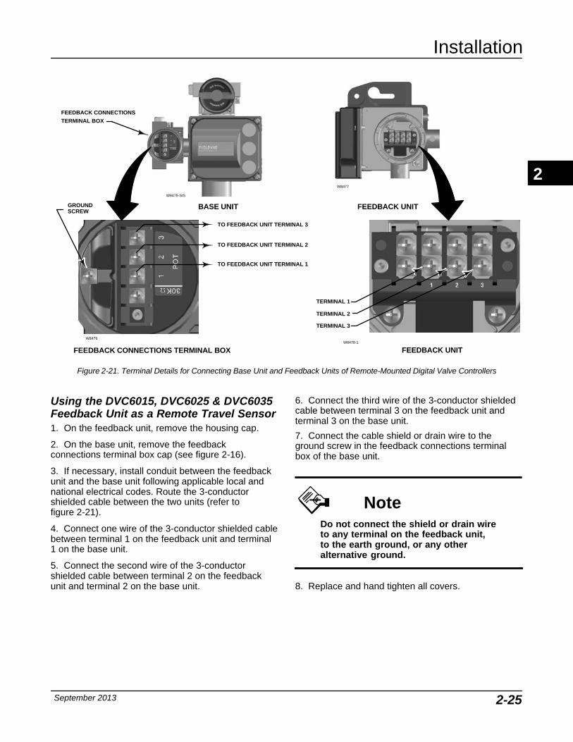
Installation
September 2013 2-25
FEEDBACK CONNECTIONS TERMINAL BOX FEEDBACK UNIT
TO FEEDBACK UNIT TERMINAL 3
TO FEEDBACK UNIT TERMINAL 2
TO FEEDBACK UNIT TERMINAL 1
GROUNDSCREW
TERMINAL 1
TERMINAL 3
TERMINAL 2
W8478-1
W8475-SIS
W8477
W8476
BASE UNIT FEEDBACK UNIT
FEEDBACK CONNECTIONSTERMINAL BOX
Figure 2-21. Terminal Details for Connecting Base Unit and Feedback Units of Remote-Mounted Digital Valve Controllers
Using the DVC6015, DVC6025 & DVC6035Feedback Unit as a Remote Travel Sensor1. On the feedback unit, remove the housing cap.
2. On the base unit, remove the feedbackconnections terminal box cap (see figure 2-16).
3. If necessary, install conduit between the feedbackunit and the base unit following applicable local andnational electrical codes. Route the 3-conductorshielded cable between the two units (refer to figure 2-21).
4. Connect one wire of the 3-conductor shielded cablebetween terminal 1 on the feedback unit and terminal1 on the base unit.
5. Connect the second wire of the 3-conductorshielded cable between terminal 2 on the feedbackunit and terminal 2 on the base unit.
6. Connect the third wire of the 3-conductor shieldedcable between terminal 3 on the feedback unit andterminal 3 on the base unit.
7. Connect the cable shield or drain wire to theground screw in the feedback connections terminalbox of the base unit.
NoteDo not connect the shield or drain wireto any terminal on the feedback unit,to the earth ground, or any otheralternative ground.
8. Replace and hand tighten all covers.
2
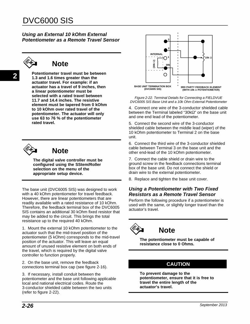
DVC6000 SIS
September 20132-26
Using an External 10 kOhm ExternalPotentiometer as a Remote Travel Sensor
NotePotentiometer travel must be between1.3 and 1.6 times greater than theactuator travel. For example: if anactuator has a travel of 9 inches, thena linear potentiometer must beselected with a rated travel between11.7 and 14.4 inches. The resistiveelement must be tapered from 0 kOhmto 10 kOhm over rated travel of thepotentiometer. The actuator will onlyuse 63 to 76 % of the potentiometerrated travel.
NoteThe digital valve controller must beconfigured using the SStem/Rollerselection on the menu of theappropriate setup device.
The base unit (DVC6005 SIS) was designed to workwith a 40 kOhm potentiometer for travel feedback.However, there are linear potentiometers that arereadily available with a rated resistance of 10 kOhm.Therefore, the feedback terminal box of the DVC6005SIS contains an additional 30 kOhm fixed resistor thatmay be added to the circuit. This brings the totalresistance up to the required 40 kOhm.
1. Mount the external 10 kOhm potentiometer to theactuator such that the mid-travel position of thepotentiometer (5 kOhm) corresponds to the mid-travelposition of the actuator. This will leave an equalamount of unused resistive element on both ends ofthe travel, which is required by the digital valvecontroller to function properly.
2. On the base unit, remove the feedbackconnections terminal box cap (see figure 2-16).
3. If necessary, install conduit between thepotentiometer and the base unit following applicablelocal and national electrical codes. Route the3-conductor shielded cable between the two units(refer to figure 2-22).
3RD PARTY FEEDBACK ELEMENT(WITH 10k � POTENTIOMETER)
(30k
�)
INTERNAL
3
1
30k
2
� 10k �
BASE UNIT TERMINATION BOX(DVC6005 SIS)
Figure 2-22. Terminal Details for Connecting a FIELDVUEDVC6005 SIS Base Unit and a 10k Ohm External Potentiometer
4. Connect one wire of the 3-conductor shielded cablebetween the Terminal labeled “30k�” on the base unitand one end lead of the potentiometer.
5. Connect the second wire of the 3-conductorshielded cable between the middle lead (wiper) of the10 kOhm potentiometer to Terminal 2 on the baseunit.
6. Connect the third wire of the 3-conductor shieldedcable between Terminal 3 on the base unit and theother end-lead of the 10 kOhm potentiometer.
7. Connect the cable shield or drain wire to theground screw in the feedback connections terminalbox of the base unit. Do not connect the shield ordrain wire to the external potentiometer.
8. Replace and tighten the base unit cover.
Using a Potentiometer with Two FixedResistors as a Remote Travel Sensor Perform the following procedure if a potentiometer isused with the same, or slightly longer travel than theactuator’s travel.
NoteThe potentiometer must be capable ofresistance close to 0 Ohms.
CAUTION
To prevent damage to thepotentiometer, ensure that it is free totravel the entire length of theactuator’s travel.
2

Installation
September 2013 2-27
NoteThe digital valve controller must beconfigured using the SStem/Rollerselection on the menu of theappropriate setup device.
This procedure uses three resistors connected inseries, two fixed resistors and one potentiometer.Three conditions must be met for the resistorcombination to correctly operate the digital valvecontroller:
� The maximum resistance of the potentiometer(Rpot(max)) must be between 3.9 kOhm and 10 kOhm.
� The resistance of R1 is 4.25 times greater thanRpot(max).
� The resistance of R2 is 4 times less thanRpot(max).
WARNING
To avoid personal injury or propertydamage from an uncontrolled processensure that the R1 resistor is properlyinsulated before installing it in theterminal box.
1. On the base unit, remove the feedbackconnections terminal box cap (see figure 2-16).
2. If necessary, install conduit between thetwo-resistor series and the base unit followingapplicable local and national electrical codes. Routethe 3-conductor shielded cable between the two units(refer to figure 2-23).
3. Install the fixed resistor (R1) across the unlabeledbottom Terminal and Terminal #1. The bottom terminaldoes not have a screw. The screw on the 30 kOhmterminal can be used. R1 must be properly insulatedwhen installed in the terminal box to prevent personalinjury or property damage.
3
1
30k�
(R2)
(R1)
2
� (Rpot)
THREE-RESISTOR SERIESBASE UNIT TERMINATION BOX(DVC6005 SIS)
Figure 2-23. Terminal Details for Connecting a FIELDVUEDVC6005 SIS Base Unit and a Three-Resistor Series
4. Connect one wire of the 3-conductor shielded cablebetween the unlabeled bottom Terminal on the baseunit and an end-lead of the external potentiometer(Rpot).
5. Connect the second wire of the 3-conductorshielded cable between the middle lead (wiper) of theexternal potentiometer (Rpot) and Terminal 2 on thebase unit.
6. Connect the third wire of the 3-conductor shieldedcable between between a lead on fixed resistor (R2)and terminal #3 of the base unit.
7. Connect the available end-lead on thepotentiometer (Rpot) with the available lead on fixedresistor (R2).
8. Connect the cable shield or drain wire to theground screw in the feedback connections terminalbox of the base unit. Do not connect the shield ordrain wire to the two-resistor series.
9. Replace and tighten the base unit cover.
Example: Using a linear potentiometer rated at 400Ohms/inch on an actuator with 16” of travel.
� Rpot(max) is 400 Ohms/in x 16” = 6.4 kOhm
� R1 = 6.4 kOhm x 4.25 = 27.2 kOhm
� R2 = 6.4 kOhm / 4 = 1.6 kOhm
2
DVC6000 SIS
September 20132-28
Test Connections
WARNING
Personal injury or property damagecaused by fire or explosion may occurif this connection is attempted in apotentially explosive atmosphere, orin an area that has been classified ashazardous. Confirm that areaclassification and atmosphereconditions permit the safe removal ofthe terminal box cap beforeproceeding.
Test connections inside the terminal box can be usedto measure loop current across a 1 ohm resistor.
1. Remove the terminal box cap.
2. Adjust the test meter to measure a range of 0.001to 0.1 volts.
3. Connect the positive lead of the test meter to theTEST + connection and the negative lead to the TEST− connection inside the terminal box.
4. Measure Loop current as:
Voltage (on test meter) � 1000 = milliamps
example:
Test meter Voltage X 1000 = Loop Milliamps
0.004 X1000 = 4.0 milliamperes
0.020 X 1000 = 20.0 milliamperes
5. Remove test leads and replace the terminal boxcover.
Communication Connections
WARNING
Personal injury or property damagecaused by fire or explosion may occurif this connection is attempted in apotentially explosive atmosphere or inan area that has been classified ashazardous. Confirm that areaclassification and atmosphereconditions permit the safe removal ofthe terminal box cap beforeproceeding.
A HART communicating device, such as a FieldCommunicator or a personal computer running
ValveLink software communicating through a HARTmodem, interfaces with the DVC6000 SIS digital valvecontroller from any wiring termination point in the 4–20mA loop. If you choose to connect the HARTcommunicating device directly to the instrument,attach the device to the LOOP + and LOOP −terminals or to the TALK + and TALK − connectionsinside the terminal box to provide localcommunications with the instrument.
Wiring Practices
Logic Solver or Control SystemRequirements There are several parameters that should be checkedto ensure the Logic Solver or control system arecompatible with the DVC6000 SIS digital valvecontroller.
Voltage Available (In a Milliamp CurrentLoop, Point-to-Point Mode Only) The voltage available at the DVC6000 SIS digital valvecontroller must be at least 11 VDC. The voltageavailable at the instrument is not the actual voltagemeasured at the instrument when the instrument isconnected. The voltage measured at the instrument islimited by the instrument and is typically less than thevoltage available.
As shown in figure 2-24, the voltage available at theinstrument depends upon:
� the control system compliance voltage
� if a filter or intrinsic safety barrier is used, and
� the wire type and length.
The control system compliance voltage is themaximum voltage at the control system outputterminals at which the control system can producemaximum loop current.
The voltage available at the instrument may becalculated from the following equation:
Voltage Available = [Control System ComplianceVoltage (at maximum current)] − [filter voltage drop (ifa HART filter is used)] − [total cable resistance �maximum current] − [barrier resistance x maximumcurrent].
The calculated voltage available should be greaterthan or equal to 11 VDC.
2
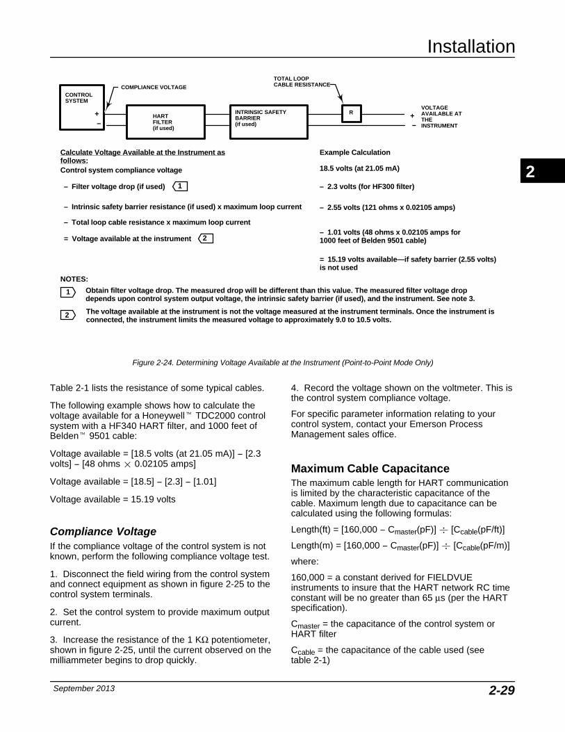
Installation
September 2013 2-29
The voltage available at the instrument is not the voltage measured at the instrument terminals. Once the instrument isconnected, the instrument limits the measured voltage to approximately 9.0 to 10.5 volts.
Obtain filter voltage drop. The measured drop will be different than this value. The measured filter voltage dropdepends upon control system output voltage, the intrinsic safety barrier (if used), and the instrument. See note 3.
HARTFILTER(if used)
CONTROLSYSTEM
+−
COMPLIANCE VOLTAGE
VOLTAGEAVAILABLE ATTHEINSTRUMENT
+−
RINTRINSIC SAFETYBARRIER(if used)
Control system compliance voltage
= Voltage available at the instrument
– Filter voltage drop (if used)
Example Calculation
18.5 volts (at 21.05 mA)
– 2.3 volts (for HF300 filter)
– Intrinsic safety barrier resistance (if used) x maximum loop current – 2.55 volts (121 ohms x 0.02105 amps)
TOTAL LOOPCABLE RESISTANCE
– Total loop cable resistance x maximum loop current– 1.01 volts (48 ohms x 0.02105 amps for1000 feet of Belden 9501 cable)
= 15.19 volts available—if safety barrier (2.55 volts)is not used
1
NOTES:
1
Calculate Voltage Available at the Instrument asfollows:
2
2
Figure 2-24. Determining Voltage Available at the Instrument (Point-to-Point Mode Only)
Table 2-1 lists the resistance of some typical cables.
The following example shows how to calculate thevoltage available for a Honeywell� TDC2000 controlsystem with a HF340 HART filter, and 1000 feet ofBelden� 9501 cable:
Voltage available = [18.5 volts (at 21.05 mA)] − [2.3volts] − [48 ohms � 0.02105 amps]
Voltage available = [18.5] − [2.3] − [1.01]
Voltage available = 15.19 volts
Compliance Voltage If the compliance voltage of the control system is notknown, perform the following compliance voltage test.
1. Disconnect the field wiring from the control systemand connect equipment as shown in figure 2-25 to thecontrol system terminals.
2. Set the control system to provide maximum outputcurrent.
3. Increase the resistance of the 1 KΩ potentiometer,shown in figure 2-25, until the current observed on themilliammeter begins to drop quickly.
4. Record the voltage shown on the voltmeter. This isthe control system compliance voltage.
For specific parameter information relating to yourcontrol system, contact your Emerson ProcessManagement sales office.
Maximum Cable Capacitance The maximum cable length for HART communicationis limited by the characteristic capacitance of thecable. Maximum length due to capacitance can becalculated using the following formulas:
Length(ft) = [160,000 − Cmaster(pF)] � [Ccable(pF/ft)]
Length(m) = [160,000 − Cmaster(pF)] � [Ccable(pF/m)]
where:
160,000 = a constant derived for FIELDVUEinstruments to insure that the HART network RC timeconstant will be no greater than 65 μs (per the HARTspecification).
Cmaster = the capacitance of the control system orHART filter
Ccable = the capacitance of the cable used (see table 2-1)
2
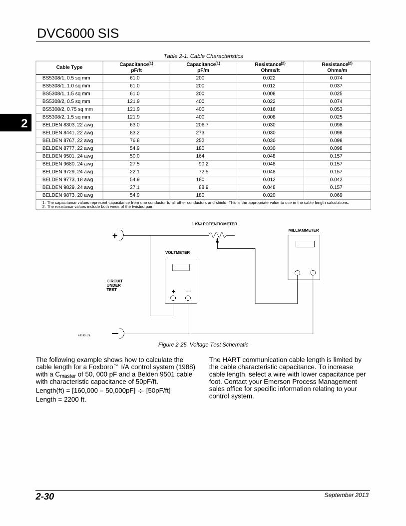
DVC6000 SIS
September 20132-30
Table 2-1. Cable Characteristics
Cable Type Capacitance(1)
pF/ftCapacitance(1)
pF/mResistance(2)
Ohms/ftResistance(2)
Ohms/m
BS5308/1, 0.5 sq mm 61.0 200 0.022 0.074
BS5308/1, 1.0 sq mm 61.0 200 0.012 0.037
BS5308/1, 1.5 sq mm 61.0 200 0.008 0.025
BS5308/2, 0.5 sq mm 121.9 400 0.022 0.074
BS5308/2, 0.75 sq mm 121.9 400 0.016 0.053
BS5308/2, 1.5 sq mm 121.9 400 0.008 0.025
BELDEN 8303, 22 awg 63.0 206.7 0.030 0.098
BELDEN 8441, 22 awg 83.2 273 0.030 0.098
BELDEN 8767, 22 awg 76.8 252 0.030 0.098
BELDEN 8777, 22 awg 54.9 180 0.030 0.098
BELDEN 9501, 24 awg 50.0 164 0.048 0.157
BELDEN 9680, 24 awg 27.5 90.2 0.048 0.157
BELDEN 9729, 24 awg 22.1 72.5 0.048 0.157
BELDEN 9773, 18 awg 54.9 180 0.012 0.042
BELDEN 9829, 24 awg 27.1 88.9 0.048 0.157
BELDEN 9873, 20 awg 54.9 180 0.020 0.0691. The capacitance values represent capacitance from one conductor to all other conductors and shield. This is the appropriate value to use in the cable length calculations.2. The resistance values include both wires of the twisted pair.
CIRCUITUNDERTEST
VOLTMETER
MILLIAMMETER
1 K� POTENTIOMETER
A6192-1/IL
Figure 2-25. Voltage Test Schematic
The following example shows how to calculate thecable length for a Foxboro� I/A control system (1988)with a Cmaster of 50, 000 pF and a Belden 9501 cablewith characteristic capacitance of 50pF/ft.Length(ft) = [160,000 − 50,000pF] � [50pF/ft]Length = 2200 ft.
The HART communication cable length is limited bythe cable characteristic capacitance. To increasecable length, select a wire with lower capacitance perfoot. Contact your Emerson Process Managementsales office for specific information relating to yourcontrol system.
2
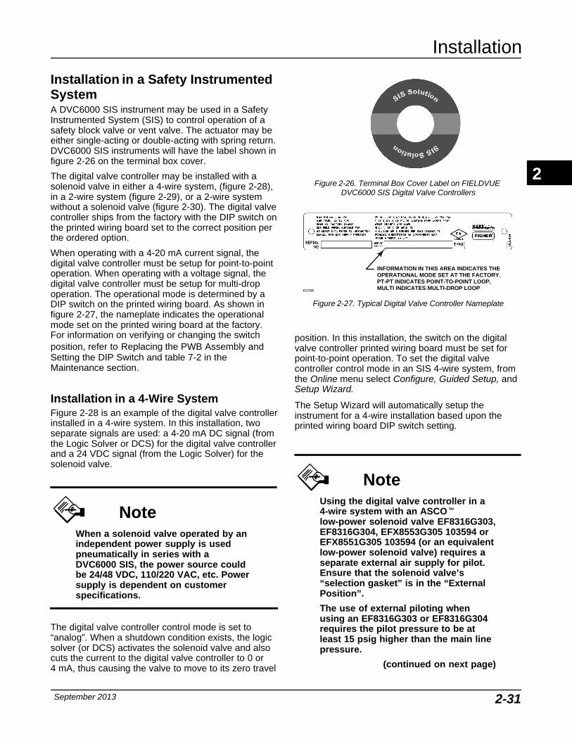
Installation
September 2013 2-31
Installation in a Safety InstrumentedSystemA DVC6000 SIS instrument may be used in a SafetyInstrumented System (SIS) to control operation of asafety block valve or vent valve. The actuator may beeither single-acting or double-acting with spring return.DVC6000 SIS instruments will have the label shown infigure 2-26 on the terminal box cover.
The digital valve controller may be installed with asolenoid valve in either a 4-wire system, (figure 2-28),in a 2-wire system (figure 2-29), or a 2-wire systemwithout a solenoid valve (figure 2-30). The digital valvecontroller ships from the factory with the DIP switch onthe printed wiring board set to the correct position perthe ordered option.
When operating with a 4-20 mA current signal, thedigital valve controller must be setup for point-to-pointoperation. When operating with a voltage signal, thedigital valve controller must be setup for multi-dropoperation. The operational mode is determined by aDIP switch on the printed wiring board. As shown infigure 2-27, the nameplate indicates the operationalmode set on the printed wiring board at the factory.For information on verifying or changing the switchposition, refer to Replacing the PWB Assembly andSetting the DIP Switch and table 7-2 in theMaintenance section.
Installation in a 4-Wire System Figure 2-28 is an example of the digital valve controllerinstalled in a 4-wire system. In this installation, twoseparate signals are used: a 4-20 mA DC signal (fromthe Logic Solver or DCS) for the digital valve controllerand a 24 VDC signal (from the Logic Solver) for thesolenoid valve.
NoteWhen a solenoid valve operated by anindependent power supply is usedpneumatically in series with aDVC6000 SIS, the power source couldbe 24/48 VDC, 110/220 VAC, etc. Powersupply is dependent on customerspecifications.
The digital valve controller control mode is set to“analog”. When a shutdown condition exists, the logicsolver (or DCS) activates the solenoid valve and alsocuts the current to the digital valve controller to 0 or 4 mA, thus causing the valve to move to its zero travel
Figure 2-26. Terminal Box Cover Label on FIELDVUE DVC6000 SIS Digital Valve Controllers
INFORMATION IN THIS AREA INDICATES THEOPERATIONAL MODE SET AT THE FACTORY.PT-PT INDICATES POINT-TO-POINT LOOP,MULTI INDICATES MULTI-DROP LOOPE0768
Figure 2-27. Typical Digital Valve Controller Nameplate
position. In this installation, the switch on the digitalvalve controller printed wiring board must be set forpoint-to-point operation. To set the digital valvecontroller control mode in an SIS 4-wire system, fromthe Online menu select Configure, Guided Setup, andSetup Wizard.
The Setup Wizard will automatically setup theinstrument for a 4-wire installation based upon theprinted wiring board DIP switch setting.
NoteUsing the digital valve controller in a4-wire system with an ASCO�low-power solenoid valve EF8316G303,EF8316G304, EFX8553G305 103594 orEFX8551G305 103594 (or an equivalentlow-power solenoid valve) requires aseparate external air supply for pilot.Ensure that the solenoid valve’s“selection gasket” is in the “ExternalPosition”.
The use of external piloting whenusing an EF8316G303 or EF8316G304requires the pilot pressure to be atleast 15 psig higher than the main linepressure.
(continued on next page)
2
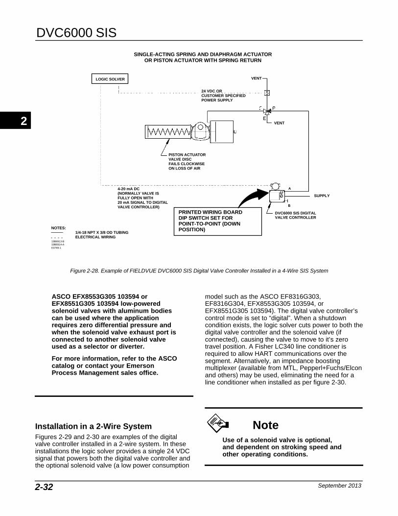
DVC6000 SIS
September 20132-32
NOTES:1/4-18 NPT X 3/8 OD TUBINGELECTRICAL WIRING
DVC6000 SIS DIGITALVALVE CONTROLLER
LOGIC SOLVER
SUPPLY
SINGLE-ACTING SPRING AND DIAPHRAGM ACTUATOROR PISTON ACTUATOR WITH SPRING RETURN
19B6913-B19B6914-AE0769-1
VENT
VENT
24 VDC OR CUSTOMER SPECIFIEDPOWER SUPPLY
4-20 mA DC(NORMALLY VALVE IS FULLY OPEN WITH20 mA SIGNAL TO DIGITALVALVE CONTROLLER)
PRINTED WIRING BOARDDIP SWITCH SET FORPOINT-TO-POINT (DOWNPOSITION)
PISTON ACTUATORVALVE DISCFAILS CLOCKWISEON LOSS OF AIR
Figure 2-28. Example of FIELDVUE DVC6000 SIS Digital Valve Controller Installed in a 4-Wire SIS System
ASCO EFX8553G305 103594 orEFX8551G305 103594 low-poweredsolenoid valves with aluminum bodiescan be used where the applicationrequires zero differential pressure andwhen the solenoid valve exhaust port isconnected to another solenoid valveused as a selector or diverter.
For more information, refer to the ASCOcatalog or contact your EmersonProcess Management sales office.
Installation in a 2-Wire System Figures 2-29 and 2-30 are examples of the digitalvalve controller installed in a 2-wire system. In theseinstallations the logic solver provides a single 24 VDCsignal that powers both the digital valve controller andthe optional solenoid valve (a low power consumption
model such as the ASCO EF8316G303,EF8316G304, EFX8553G305 103594, orEFX8551G305 103594). The digital valve controller’scontrol mode is set to “digital”. When a shutdowncondition exists, the logic solver cuts power to both thedigital valve controller and the solenoid valve (ifconnected), causing the valve to move to it’s zerotravel position. A Fisher LC340 line conditioner isrequired to allow HART communications over thesegment. Alternatively, an impedance boostingmultiplexer (available from MTL, Pepperl+Fuchs/Elconand others) may be used, eliminating the need for aline conditioner when installed as per figure 2-30.
NoteUse of a solenoid valve is optional,and dependent on stroking speed andother operating conditions.
2
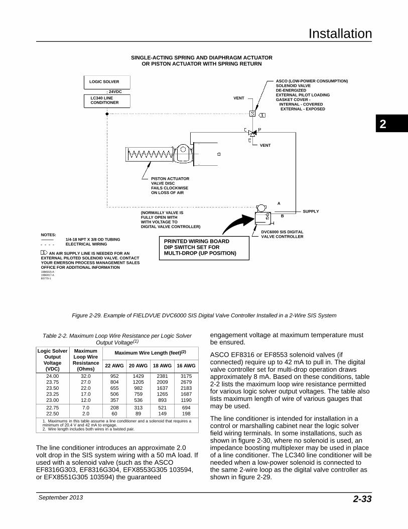
Installation
September 2013 2-33
NOTES:1/4-18 NPT X 3/8 OD TUBINGELECTRICAL WIRING
AN AIR SUPPLY LINE IS NEEDED FOR ANEXTERNAL PILOTED SOLENOID VALVE. CONTACTYOUR EMERSON PROCESS MANAGEMENT SALESOFFICE FOR ADDITIONAL INFORMATION
LOGIC SOLVER
LC340 LINE CONDITIONER
DVC6000 SIS DIGITALVALVE CONTROLLER
SINGLE-ACTING SPRING AND DIAPHRAGM ACTUATOROR PISTON ACTUATOR WITH SPRING RETURN
ASCO (LOW-POWER CONSUMPTION)SOLENOID VALVEDE-ENERGIZEDEXTERNAL PILOT LOADINGGASKET COVER - INTERNAL - COVERED EXTERNAL - EXPOSED
(NORMALLY VALVE IS FULLY OPEN WITHWITH VOLTAGE TO DIGITAL VALVE CONTROLLER)
PISTON ACTUATORVALVE DISCFAILS CLOCKWISEON LOSS OF AIR
VENT
VENT
24VDC
PRINTED WIRING BOARDDIP SWITCH SET FOR MULTI-DROP (UP POSITION)
19B6915-A19B6917-AE0770-1
1
1
A
BSUPPLY
Figure 2-29. Example of FIELDVUE DVC6000 SIS Digital Valve Controller Installed in a 2-Wire SIS System
Table 2-2. Maximum Loop Wire Resistance per Logic SolverOutput Voltage(1)
Logic SolverOutputVoltage(VDC)
MaximumLoop WireResistance
(Ohms)
Maximum Wire Length (feet)(2)
22 AWG 20 AWG 18 AWG 16 AWG
24.0023.7523.5023.2523.00
32.027.022.017.012.0
952804655506357
14291205982759536
2381200916371265893
31752679218316871190
22.7522.50
7.02.0
20860
31389
521149
694198
1. Maximums in this table assume a line conditioner and a solenoid that requires aminimum of 20.4 V and 42 mA to engage.2. Wire length includes both wires in a twisted pair.
The line conditioner introduces an approximate 2.0volt drop in the SIS system wiring with a 50 mA load. Ifused with a solenoid valve (such as the ASCOEF8316G303, EF8316G304, EFX8553G305 103594,or EFX8551G305 103594) the guaranteed
engagement voltage at maximum temperature mustbe ensured.
ASCO EF8316 or EF8553 solenoid valves (ifconnected) require up to 42 mA to pull in. The digitalvalve controller set for multi-drop operation drawsapproximately 8 mA. Based on these conditions, table2-2 lists the maximum loop wire resistance permittedfor various logic solver output voltages. The table alsolists maximum length of wire of various gauges thatmay be used.
The line conditioner is intended for installation in acontrol or marshalling cabinet near the logic solverfield wiring terminals. In some installations, such asshown in figure 2-30, where no solenoid is used, animpedance boosting multiplexer may be used in placeof a line conditioner. The LC340 line conditioner will beneeded when a low-power solenoid is connected tothe same 2-wire loop as the digital valve controller asshown in figure 2-29.
2
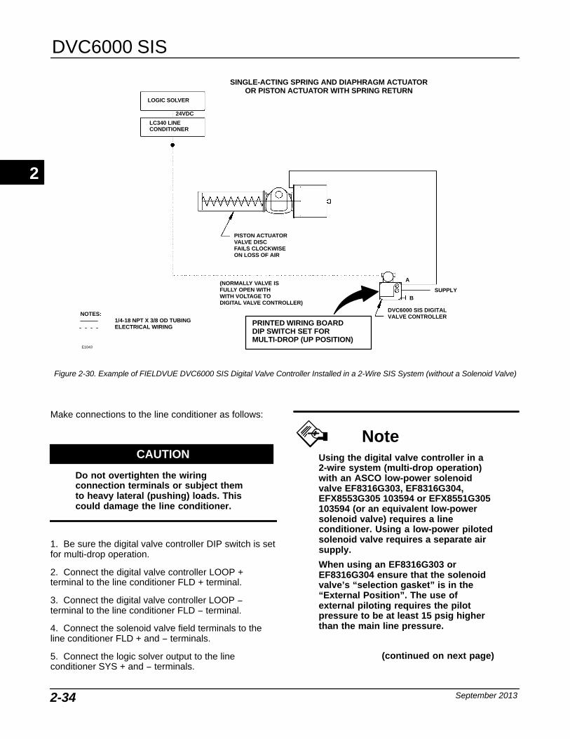
DVC6000 SIS
September 20132-34
NOTES:1/4-18 NPT X 3/8 OD TUBINGELECTRICAL WIRING
LOGIC SOLVER
LC340 LINE CONDITIONER
DVC6000 SIS DIGITALVALVE CONTROLLER
SINGLE-ACTING SPRING AND DIAPHRAGM ACTUATOROR PISTON ACTUATOR WITH SPRING RETURN
(NORMALLY VALVE IS FULLY OPEN WITHWITH VOLTAGE TO DIGITAL VALVE CONTROLLER)
PISTON ACTUATORVALVE DISCFAILS CLOCKWISEON LOSS OF AIR
24VDC
PRINTED WIRING BOARDDIP SWITCH SET FOR MULTI-DROP (UP POSITION)
E1043
A
BSUPPLY
Figure 2-30. Example of FIELDVUE DVC6000 SIS Digital Valve Controller Installed in a 2-Wire SIS System (without a Solenoid Valve)
Make connections to the line conditioner as follows:
CAUTION
Do not overtighten the wiringconnection terminals or subject themto heavy lateral (pushing) loads. Thiscould damage the line conditioner.
1. Be sure the digital valve controller DIP switch is setfor multi-drop operation.
2. Connect the digital valve controller LOOP +terminal to the line conditioner FLD + terminal.
3. Connect the digital valve controller LOOP −terminal to the line conditioner FLD − terminal.
4. Connect the solenoid valve field terminals to theline conditioner FLD + and − terminals.
5. Connect the logic solver output to the lineconditioner SYS + and − terminals.
NoteUsing the digital valve controller in a2-wire system (multi-drop operation)with an ASCO low-power solenoidvalve EF8316G303, EF8316G304,EFX8553G305 103594 or EFX8551G305103594 (or an equivalent low-powersolenoid valve) requires a lineconditioner. Using a low-power pilotedsolenoid valve requires a separate airsupply.
When using an EF8316G303 orEF8316G304 ensure that the solenoidvalve’s “selection gasket” is in the“External Position”. The use ofexternal piloting requires the pilotpressure to be at least 15 psig higherthan the main line pressure.
(continued on next page)
2
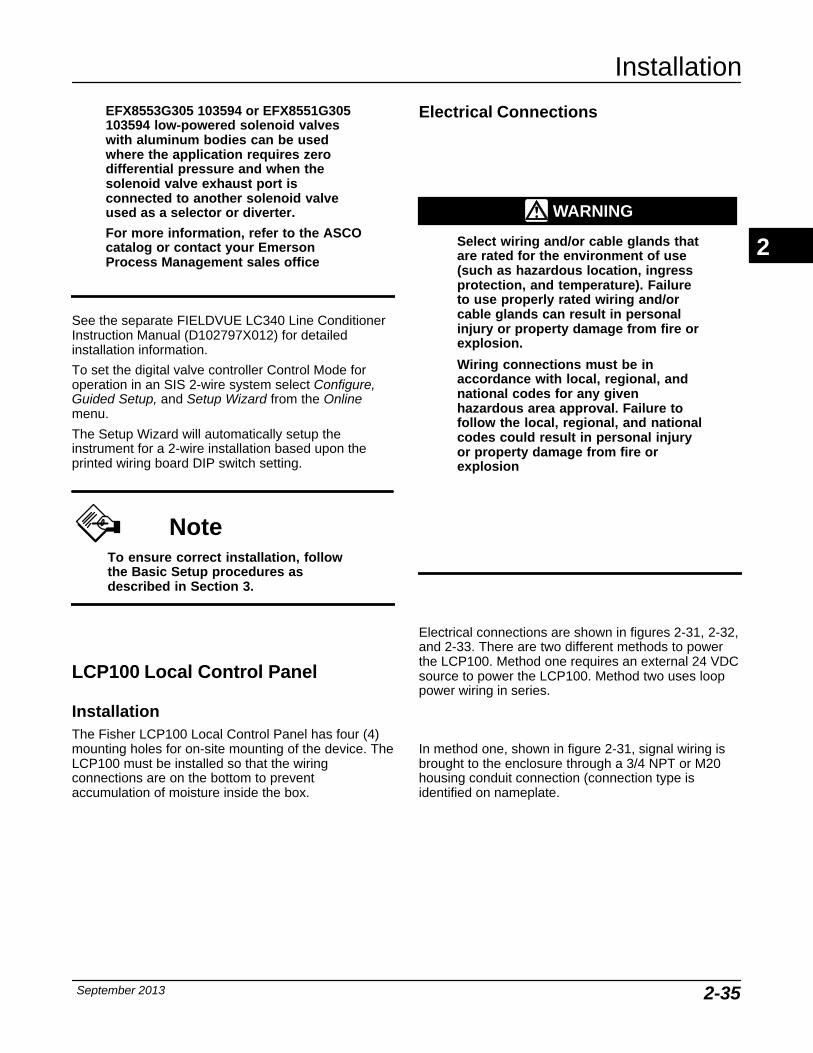
Installation
September 2013 2-35
EFX8553G305 103594 or EFX8551G305103594 low-powered solenoid valveswith aluminum bodies can be usedwhere the application requires zerodifferential pressure and when thesolenoid valve exhaust port isconnected to another solenoid valveused as a selector or diverter.
For more information, refer to the ASCOcatalog or contact your EmersonProcess Management sales office
See the separate FIELDVUE LC340 Line ConditionerInstruction Manual (D102797X012) for detailedinstallation information.
To set the digital valve controller Control Mode foroperation in an SIS 2-wire system select Configure,Guided Setup, and Setup Wizard from the Onlinemenu.
The Setup Wizard will automatically setup theinstrument for a 2-wire installation based upon theprinted wiring board DIP switch setting.
NoteTo ensure correct installation, followthe Basic Setup procedures asdescribed in Section 3.
LCP100 Local Control Panel
Installation The Fisher LCP100 Local Control Panel has four (4)mounting holes for on-site mounting of the device. TheLCP100 must be installed so that the wiringconnections are on the bottom to preventaccumulation of moisture inside the box.
Electrical Connections
WARNING
Select wiring and/or cable glands thatare rated for the environment of use(such as hazardous location, ingressprotection, and temperature). Failureto use properly rated wiring and/orcable glands can result in personalinjury or property damage from fire orexplosion.
Wiring connections must be inaccordance with local, regional, andnational codes for any givenhazardous area approval. Failure tofollow the local, regional, and nationalcodes could result in personal injuryor property damage from fire orexplosion
Electrical connections are shown in figures 2-31, 2-32,and 2-33. There are two different methods to powerthe LCP100. Method one requires an external 24 VDCsource to power the LCP100. Method two uses looppower wiring in series.
In method one, shown in figure 2-31, signal wiring isbrought to the enclosure through a 3/4 NPT or M20housing conduit connection (connection type isidentified on nameplate.
2
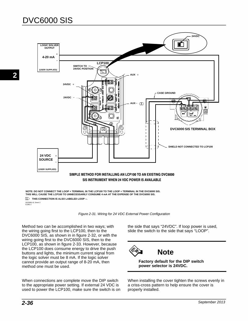
DVC6000 SIS
September 20132-36
NOTE: DO NOT CONNECT THE LOOP + TERMINAL IN THE LCP100 TO THE LOOP + TERMINAL IN THE DVC6000 SIS. THIS WILL CAUSE THE LCP100 TO UNNECESSARILY CONSUME 4 mA AT THE EXPENSE OF THE DVC6000 SIS.
SIMPLE METHOD FOR INSTALLING AN LCP100 TO AN EXISTING DVC6000SIS INSTRUMENT WHEN 24 VDC POWER IS AVAILABLE
GE26881-B, Sheet 3E1082-2
SWITCH TO24VDC POSITION
(USER SUPPLIED)
24 VDC
(USER SUPPLIED)
4-20 mA
AUX �
AUX�
CASE GROUND
SHIELD NOT CONNECTED TO LCP100
24VDC �
DVC6000 SIS TERMINAL BOX
LCP100
SOURCE
24VDC �
�
�
1
1
THIS CONNECTION IS ALSO LABELED LOOP −.
LOGIC SOLVEROUTPUT
�
�
24VDC
Figure 2-31. Wiring for 24 VDC External Power Configuration
Method two can be accomplished in two ways; withthe wiring going first to the LCP100, then to theDVC6000 SIS, as shown in in figure 2-32, or with thewiring going first to the DVC6000 SIS, then to theLCP100, as shown in figure 2-33. However, becausethe LCP100 does consume energy to drive the pushbuttons and lights, the minimum current signal fromthe logic solver must be 8 mA. If the logic solvercannot provide an output range of 8-20 mA, thenmethod one must be used.
When connections are complete move the DIP switchto the appropriate power setting. If external 24 VDC isused to power the LCP100, make sure the switch is on
the side that says “24VDC”. If loop power is used,slide the switch to the side that says “LOOP”.
NoteFactory default for the DIP switchpower selector is 24VDC.
When installing the cover tighten the screws evenly ina criss-cross pattern to help ensure the cover isproperly installed.
2
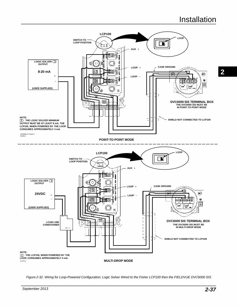
Installation
September 2013 2-37
NOTE: THE LOGIC SOLVER MINIMUM
OUTPUT MUST BE AT LEAST 8 mA. THELCP100, WHEN POWERED BY THE LOOP,CONSUMES APPROXIMATELY 4 mA.
AUX �
LOOP �
LOOP �
SWITCH TOLOOP POSITION
CASE GROUND
SHIELD NOT CONNECTED TO LCP100
DVC6000 SIS TERMINAL BOX
LCP100
�
�
LOGIC SOLVEROUTPUT
1
1
(USER SUPPLIED)
THE DVC6000 SIS MUST BEIN POINT-TO-POINT MODE
LOOP
GE26881-B, Sheet 2E1084-1
8-20 mA
NOTE: THE LCP100, WHEN POWERED BY THE
LOOP, CONSUMES APPROXIMATELY 4 mA.
AUX �
LOOP �
LOOP �
SWITCH TO LOOP POSITION
CASE GROUND
SHIELD NOT CONNECTED TO LCP100
DVC6000 SIS TERMINAL BOX
LCP100
24VDC�
�
LOGIC SOLVEROUTPUT
1
1
(USER SUPPLIED)
SYS − /�
FLD − /�
THE DVC6000 SIS MUST BEIN MULTI-DROP MODE
POINT-TO-POINT MODE
MULTI-DROP MODE
LC340 LINECONDITIONER
LOOP
E1375-1
Figure 2-32. Wiring for Loop-Powered Configuration; Logic Solver Wired to the Fisher LCP100 then the FIELDVUE DVC6000 SIS
2
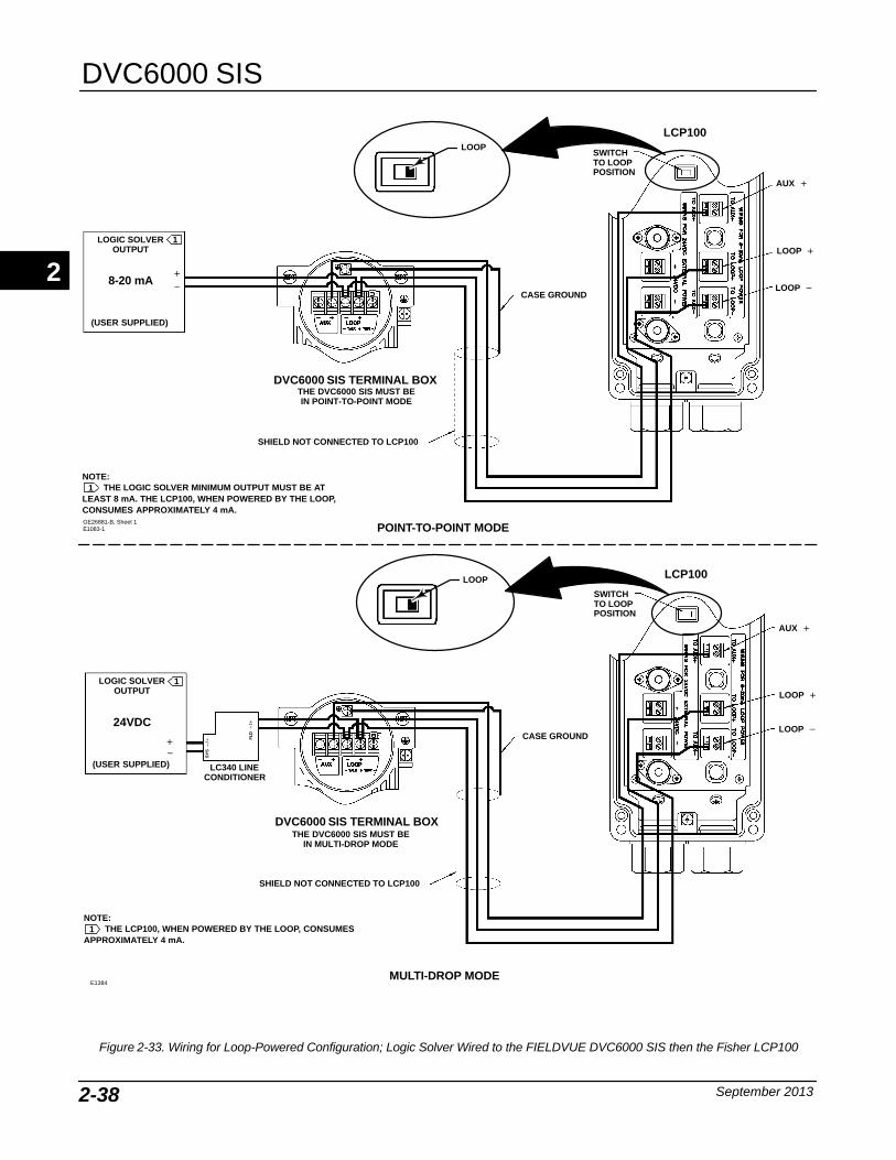
DVC6000 SIS
September 20132-38
GE26881-B, Sheet 1E1083-1
NOTE:THE LOGIC SOLVER MINIMUM OUTPUT MUST BE AT
LEAST 8 mA. THE LCP100, WHEN POWERED BY THE LOOP,CONSUMES APPROXIMATELY 4 mA.
SWITCHTO LOOPPOSITION
8-20 mA�
(USER SUPPLIED)
AUX �
LOOP �
LOOP �
CASE GROUND
DVC6000 SIS TERMINAL BOX
SHIELD NOT CONNECTED TO LCP100
LCP100
�
LOGIC SOLVEROUTPUT
1
1
POINT-TO-POINT MODE
NOTE:THE LCP100, WHEN POWERED BY THE LOOP, CONSUMES
APPROXIMATELY 4 mA.
SWITCHTO LOOPPOSITION
24VDC
�
(USER SUPPLIED)
CASE GROUND
DVC6000 SIS TERMINAL BOX
SHIELD NOT CONNECTED TO LCP100
LCP100
�
LOGIC SOLVEROUTPUT
1
1
MULTI-DROP MODE
AUX �
LOOP �
LOOP �
THE DVC6000 SIS MUST BEIN POINT-TO-POINT MODE
THE DVC6000 SIS MUST BEIN MULTI-DROP MODE
LC340 LINECONDITIONER
SY
S −
/�
FLD
−
/�
LOOP
LOOP
E1384
Figure 2-33. Wiring for Loop-Powered Configuration; Logic Solver Wired to the FIELDVUE DVC6000 SIS then the Fisher LCP100
2
Basic Setup
September 2013 3-1
3-3
Section 3 Basic Setup
Configuration Protection 3-2. . . . . . . . . . . . . . . . . . . . . . . . . . . . . . . . . . . . . . . . . . . . . . .
Instrument Mode 3-2. . . . . . . . . . . . . . . . . . . . . . . . . . . . . . . . . . . . . . . . . . . . . . . . . . . . . . . .
Guided Setup 3-2. . . . . . . . . . . . . . . . . . . . . . . . . . . . . . . . . . . . . . . . . . . . . . . . . . . . . . . . . . . .
Setup Wizard 3-3. . . . . . . . . . . . . . . . . . . . . . . . . . . . . . . . . . . . . . . . . . . . . . . . . . . . . . . . . . . . .
Performance Tuner 3-6. . . . . . . . . . . . . . . . . . . . . . . . . . . . . . . . . . . . . . . . . . . . . . . . . . . . . . . .
3
DVC6000 SIS
September 20133-2
Configuration Protection To setup and calibrate the instrument, the protectionmust be set to None with the Field Communicator. Ifthe protection is not None, changing the protectionrequires placing a jumper across the Auxiliaryterminals in the terminal box.
NoteWhen a Fisher LCP100 control panel isused, changing protection does notrequire placing the jumper across theAuxiliary terminals in the terminal box.
To remove protection:
1. Connect a 4-20 mA source to the instrument.
2. Connect the Field Communicator to the instrumentand turn it on.
3. Press the Hot key on the Field Communicator andselect Protection.
4. From the Protection menu, select None. Whenprompted by the Field Communicator, temporarilyattach the jumper to the AUX + and AUX − terminalsin the instrument terminal box.
Instrument Mode To setup and calibrate the instrument, the instrumentmode must be Out Of Service.
To view/change the instrument mode, press the HotKey and select Instrument Mode. If the mode is notOut Of Service, select Out Of Service from theInstrument Mode menu and press ENTER.
Instrument Mode allows you to either take theinstrument Out of Service or place it In Service.Taking the instrument Out of Service allows you toperform instrument calibration and also allows you tochange setup variables that affect control. See SettingProtection to ensure protection is set correctly prior tooperation.
Guided Setup
WARNING
Changes to the instrument setup maycause changes in the output pressureor valve travel. Depending on theapplication, these changes may upsetprocess control, which could result inpersonal injury or property damage.
WARNING
To avoid personal injury or equipmentdamage caused by the release ofprocess pressure, always use theSetup Wizard to perform setup andcalibration before placing theDVC6000 SIS in operation for the firsttime. The Setup Wizard sets up therequired parameters for SIS solutions.
NoteTo setup and calibrate the instrument,the protection must be None and theInstrument Mode must be Out OfService. See Configuration Protectionand Instrument Mode at the beginningof this section for information onremoving instrument protection andchanging the instrument mode.
3
Basic Setup
September 2013 3-3
NoteIn the event of a power failure theDVC6000 SIS automatically restoresthe device to In Service uponrestoration of power. This is to providegreater availability of the safetyfunction.
If power is inadvertently interruptedwhile performing set up ormaintenance, you may need to returnthe DVC6000 SIS to out of service ifthe interrupted task requires that modeof operation.
When the DVC6000 SIS digital valve controller isordered as part of a control valve assembly, thefactory mounts the digital valve controller and sets upthe instrument as specified on the order. Whenmounting to a valve in the field, the instrument needsto be set up to match the instrument to the valve andactuator.
Before beginning Guided Setup, be sure theinstrument is correctly mounted as described in theInstallation section.
Setup Wizard (1-1-1)
NoteThe Setup Wizard must be run for firsttime installations before placing theDVC6000 SIS in service.
Use the Setup Wizard to setup the digital valvecontroller for operation in an SIS solution. The SetupWizard automatically sets up the instrument usingspecified actuator information. To access the SetupWizard from the Online Menu select Configure,Guided Setup, and Setup Wizard.
1. When prompted by the Setup Wizard, enter thepressure units (psi, bar, kPa, or kg/cm2).
2. Enter the maximum instrument supply pressure.
After entering the maximum instrument supplypressure, the Setup Wizard prompts you for actuatorinformation.
3. Enter the partial stroke test start point.
4. Indicate if the DVC6000 SIS is connected to anLCP100.
5. Enter the manufacturer of the actuator on whichthe instrument is mounted. If the actuatormanufacturer is not listed, select Other.
6. Enter the actuator model or type. If the actuatormodel is not listed, select Other.
7. Enter the actuator size.
8. Enter the Relay Type.
9. Select whether the valve is open or closed underthe zero power condition, if prompted.
NoteWhen completing steps 3 through 9,refer to table 3-1 for possibleconfigurations for a digital valvecontroller operated by a 4-20 mA inputcurrent (point-to-point mode), andtable 3-2 for possible configurationsfor a digital valve controller operatedby a 0-24 VDC power supply(multi-drop mode).
WARNING
If you answer YES to the prompt forpermission to move the valve whenthe Field Communicator isdetermining the travel sensor motion,the instrument will move the valvethrough its full travel range. To avoidpersonal injury and property damagecaused by the release of pressure orprocess fluid, provide sometemporary means of control for theprocess.
10. Indicate if a volume booster or quick release ispresent.
3
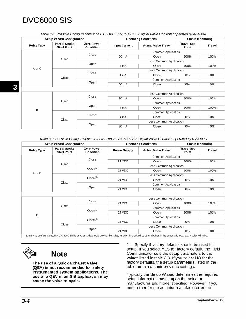
DVC6000 SIS
September 20133-4
Table 3-1. Possible Configurations for a FIELDVUE DVC6000 SIS Digital Valve Controller operated by 4-20 mASetup Wizard Configuration Operating Conditions Status Monitoring
Relay Type Partial StrokeStart Point
Zero PowerCondition
Input Current Actual Valve Travel Travel SetPoint
Travel
A or C
Open
CloseCommon Application
20 mA Open 100% 100%
OpenLess Common Application
4 mA Open 100% 100%
Close
CloseLess Common Application
4 mA Close 0% 0%
OpenCommon Application
20 mA Close 0% 0%
B
Open
CloseLess Common Application
20 mA Open 100% 100%
OpenCommon Application
4 mA Open 100% 100%
Close
CloseCommon Application
4 mA Close 0% 0%
OpenLess Common Application
20 mA Close 0% 0%
Table 3-2. Possible Configurations for a FIELDVUE DVC6000 SIS Digital Valve Controller operated by 0-24 VDCSetup Wizard Configuration Operating Conditions Status Monitoring
Relay Type Partial StrokeStart Point
Zero PowerCondition
Power Supply Actual Valve Travel Travel SetPoint
Travel
A or C
Open
CloseCommon Application
24 VDC Open 100% 100%
Open(1)Less Common Application
24 VDC Open 100% 100%
Close
Close(1)Less Common Application
24 VDC Close 0% 0%
OpenCommon Application
24 VDC Close 0% 0%
B
Open
CloseLess Common Application
24 VDC Open 100% 100%
Open(1)Common Application
24 VDC Open 100% 100%
Close
Close(1)Common Application
24 VDC Close 0% 0%
OpenLess Common Application
24 VDC Close 0% 0%1. In these configurations, the DVC6000 SIS is used as a diagnostic device, the safety function is provided by other devices in the pneumatic loop, e.g. a solenoid valve.
NoteThe use of a Quick Exhaust Valve(QEV) is not recommended for safetyinstrumented system applications. Theuse of a QEV in an SIS application maycause the valve to cycle.
11. Specify if factory defaults should be used forsetup. If you select YES for factory default, the FieldCommunicator sets the setup parameters to thevalues listed in table 3-3. If you select NO for thefactory defaults, the setup parameters listed in thetable remain at their previous settings.
Typically the Setup Wizard determines the requiredsetup information based upon the actuatormanufacturer and model specified. However, if youenter other for the actuator manufacturer or the
3
Basic Setup
September 2013 3-5
actuator model, then you will be prompted for setupparameters such as:
Actuator Style (select spring & diaphragm, pistonsingle-acting with spring, piston double-acting withspring)
Valve Style (select the valve style, rotary or slidingstem)
On Loss of Instrument Signal, (valve opens orcloses). See Zero Power Condition in the DetailedSetup section.
Feedback Connection (select Rot-All, SS-roller, orSStem-Standard). See Feedback Connection in theDetailed Setup section.
Partial Stroke Start Point (select the start point forthe Partial Stroke Test; either Valve Open or ValveClose).
LCP100 Local Control Panel (indicate if theinstrument is connected to an LCP100 local controlpanel).
Travel Sensor Motion (increasing air pressurecauses the travel sensor shaft to rotate clockwise orcounterclockwise), the Setup Wizard will ask if it canmove the valve to determine travel sensor motion.
If you answer yes, the instrument may stroke the valvethe full travel span to determine travel sensor rotation.If you answer No, then you will have to specify therotation for increasing air pressure (determine therotation by viewing the end of the travel sensor shaft).See Travel Sensor Motion in the Detailed Setupsection.
Tuning Set (see Tuning Set in the Detailed Setupsection).
After choosing the appropriate tuning set, a messageappears on the display, asking if you would like todownload factory defaults for Setup. Yes isrecommended for Initial Setup. Refer to table 3-3 forfactory download defaults.
Follow the prompts on the Field Communicatordisplay. The calibration procedure uses the valve andactuator stops as the 0% and 100% calibration points.For additional information, refer to Auto CalibrateTravel in the Calibration section.
Once Auto Calibration is complete, you will be askedto enter the desired stroke test speed (default is0.25%/sec). An additional automatic PST calibration isrun to determine the default value or the partial strokepressure limit for single acting actuators (this will bedifferential pressure for double acting) and pressureset point for End Point Pressure Control.
When calibration is complete, you are asked if youwish to adjust the relay (double-acting only). Selectyes to adjust the relay. For additional information, referto Relay Adjustment in the Calibration section.
Table 3-3. Factory Download Default SettingsSetup Parameter Default Setting
Analog Input Units(1)
Analog In Range High(1)
Analog In Range Low(1)
Control Mode
Restart Control Mode
mA20.0 mA4.0 mAAnalog(1)
Digital(2)
Analog(1)
Digital(2)
Lag TimeInput CharacteristicTravel Limit HighTravel Limit Low
0 secsLinear125%−25%
Travel Cutoff HighTravel Cutoff LowTravel Deviation Alert PointTravel Deviation TimeSet Point Rate Open(3)
Set Point Rate Close(4)
Polling Address
50%50%5.0%10.0 seconds0%/sec0%/sec0
Pressure Deviation Alert PointPressure Deviation Alert Time
5.0 psi(5)
30.0 seconds
Command #3 (Trending) PressureFor double-acting actuatorsFor single-acting actuators
differential output pressureactuator pressure
Valve Set Point(2)
Restart Travel Set Point(2)
Self-Test Shutdown(2)
100% if ZPC = Open0% if ZPC = Closed100% if ZPC = Open0% if ZPC = ClosedAll Failures Disabled
1. Analog mode only − DIP switch set to Pt-Pt.2. Digital mode only. − DIP switch set to Multi.3. In firmware 3 thru 6 this parameter is labeled Minimum Opening Time.In firmware 10 and below this parameter should be set to zero.4. In firmware 3 thru 6 this parameter is labeled Minimum Closing Time.In firmware 10 and below this parameter should be set to zero.5. Adjust to bar, kPa, or kg/cm2 if necessary.
NoteRelay Adjustment is only available forthe double-acting relay (Relay A).
After instrument setup is completed, and you haveplaced the instrument in service, if End Point PressureControl not enabled, you will be prompted to enable it.Select yes. Refer to Partial Stroke Variables in theDetailed Setup section for more information.
If after completing auto setup and auto calibration thevalve seems slightly unstable or unresponsive, youcan improve operation by selecting PerformanceTuner from the Guided Setup menu. For additionalinformation on using the Performance Tuner tooptimize digital valve controller tuning, refer to thePerformance Tuner information below.
3
DVC6000 SIS
September 20133-6
Performance Tuner (1-1-2)
WARNING
During performance tuning the valvemay move, causing process fluid orpressure to be released. To avoidpersonal injury and property damagecaused by the release of process fluidor pressure, isolate the valve from theprocess and equalize pressure onboth sides of the valve or bleed offthe process fluid.
The Performance Tuner is used to optimize digitalvalve controller tuning. It can be used with digital valvecontrollers mounted on most sliding-stem and rotaryactuators, including Fisher and other manufacturers’products. Moreover, because the Performance Tunercan detect internal instabilities before they becomeapparent in the travel response, it can generallyoptimize tuning more effectively than manual tuning.Typically, the Performance Tuner takes 3 to 5 minutesto tune an instrument, although tuning instrumentsmounted on larger actuators may take longer.
Access the Performance Tuner by selectingPerformance Tuner from the Guided Setup menu.Follow the prompts on the Field Communicator displayto optimize digital valve controller tuning.
3
Detailed Setup
September 2013 4-1
4-4
Section 4 Detailed Setup
Menu and Quick Key Sequence Tables Front Cover. . . . . . . . . . . . . . . . . . . . . . . . . . . . . . .
Detailed Setup 4-2. . . . . . . . . . . . . . . . . . . . . . . . . . . . . . . . . . . . . . . . . . . . . . . . . . . . . . . . . . .
Mode and Protection 4-2. . . . . . . . . . . . . . . . . . . . . . . . . . . . . . . . . . . . . . . . . . . . . . . . . . . . . . .Mode 4-2. . . . . . . . . . . . . . . . . . . . . . . . . . . . . . . . . . . . . . . . . . . . . . . . . . . . . . . . . . . . . . . . . . .Protection 4-4. . . . . . . . . . . . . . . . . . . . . . . . . . . . . . . . . . . . . . . . . . . . . . . . . . . . . . . . . . . . . . .
Response Control 4-4. . . . . . . . . . . . . . . . . . . . . . . . . . . . . . . . . . . . . . . . . . . . . . . . . . . . . . . . .Tuning 4-4. . . . . . . . . . . . . . . . . . . . . . . . . . . . . . . . . . . . . . . . . . . . . . . . . . . . . . . . . . . . . . . . . .
Travel Tuning 4-4. . . . . . . . . . . . . . . . . . . . . . . . . . . . . . . . . . . . . . . . . . . . . . . . . . . . . . . . . .Integral Settings 4-8. . . . . . . . . . . . . . . . . . . . . . . . . . . . . . . . . . . . . . . . . . . . . . . . . . . . . . .Pressure Tuning 4-9. . . . . . . . . . . . . . . . . . . . . . . . . . . . . . . . . . . . . . . . . . . . . . . . . . . . . . .
Travel/Pressure Control 4-10. . . . . . . . . . . . . . . . . . . . . . . . . . . . . . . . . . . . . . . . . . . . . . . . . . .Travel/Pressure Cutoffs 4-10. . . . . . . . . . . . . . . . . . . . . . . . . . . . . . . . . . . . . . . . . . . . . . . . .End Point Pressure Control 4-11. . . . . . . . . . . . . . . . . . . . . . . . . . . . . . . . . . . . . . . . . . . . . .
Input Characterization 4-11. . . . . . . . . . . . . . . . . . . . . . . . . . . . . . . . . . . . . . . . . . . . . . . . . . . .Custom Characterization Table 4-12. . . . . . . . . . . . . . . . . . . . . . . . . . . . . . . . . . . . . . . . . . . .Dynamic Response 4-12. . . . . . . . . . . . . . . . . . . . . . . . . . . . . . . . . . . . . . . . . . . . . . . . . . . . . . .
Alert Setup 4-13. . . . . . . . . . . . . . . . . . . . . . . . . . . . . . . . . . . . . . . . . . . . . . . . . . . . . . . . . . . . . . .Electronic Alerts 4-13. . . . . . . . . . . . . . . . . . . . . . . . . . . . . . . . . . . . . . . . . . . . . . . . . . . . . . . . .Sensor Alerts 4-14. . . . . . . . . . . . . . . . . . . . . . . . . . . . . . . . . . . . . . . . . . . . . . . . . . . . . . . . . . . .Environmental Alerts 4-14. . . . . . . . . . . . . . . . . . . . . . . . . . . . . . . . . . . . . . . . . . . . . . . . . . . . .Travel Alerts 4-14. . . . . . . . . . . . . . . . . . . . . . . . . . . . . . . . . . . . . . . . . . . . . . . . . . . . . . . . . . . . .Travel History Alerts 4-15. . . . . . . . . . . . . . . . . . . . . . . . . . . . . . . . . . . . . . . . . . . . . . . . . . . . . .SIS Alerts 4-16. . . . . . . . . . . . . . . . . . . . . . . . . . . . . . . . . . . . . . . . . . . . . . . . . . . . . . . . . . . . . . .Alert Record 4-17. . . . . . . . . . . . . . . . . . . . . . . . . . . . . . . . . . . . . . . . . . . . . . . . . . . . . . . . . . . . .
Status 4-17. . . . . . . . . . . . . . . . . . . . . . . . . . . . . . . . . . . . . . . . . . . . . . . . . . . . . . . . . . . . . . . . . . .
Instrument 4-18. . . . . . . . . . . . . . . . . . . . . . . . . . . . . . . . . . . . . . . . . . . . . . . . . . . . . . . . . . . . . . . .
Valve & Actuator 4-19. . . . . . . . . . . . . . . . . . . . . . . . . . . . . . . . . . . . . . . . . . . . . . . . . . . . . . . . . .
Partial Stroke 4-20. . . . . . . . . . . . . . . . . . . . . . . . . . . . . . . . . . . . . . . . . . . . . . . . . . . . . . . . . . . . .
4
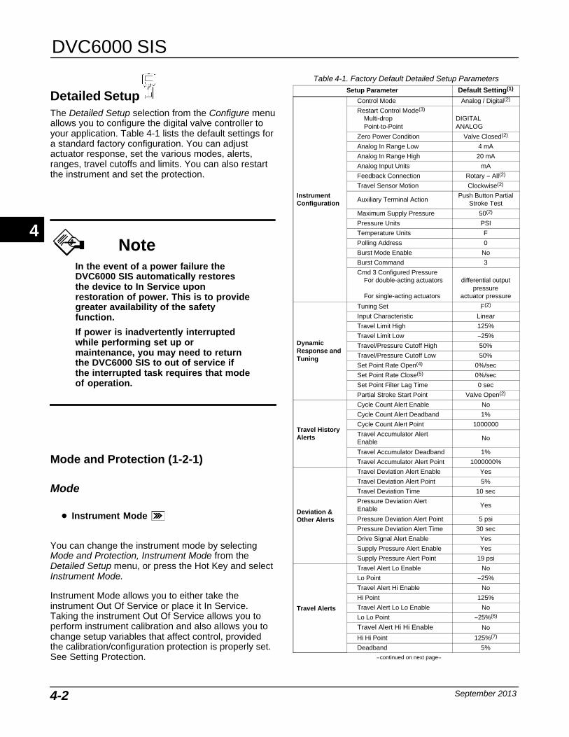
DVC6000 SIS
September 20134-2
Detailed SetupThe Detailed Setup selection from the Configure menuallows you to configure the digital valve controller toyour application. Table 4-1 lists the default settings fora standard factory configuration. You can adjustactuator response, set the various modes, alerts,ranges, travel cutoffs and limits. You can also restartthe instrument and set the protection.
NoteIn the event of a power failure theDVC6000 SIS automatically restoresthe device to In Service uponrestoration of power. This is to providegreater availability of the safetyfunction.
If power is inadvertently interruptedwhile performing set up ormaintenance, you may need to returnthe DVC6000 SIS to out of service ifthe interrupted task requires that modeof operation.
Mode and Protection (1-2-1)
Mode
� Instrument Mode
You can change the instrument mode by selectingMode and Protection, Instrument Mode from theDetailed Setup menu, or press the Hot Key and selectInstrument Mode.
Instrument Mode allows you to either take theinstrument Out Of Service or place it In Service.Taking the instrument Out Of Service allows you toperform instrument calibration and also allows you tochange setup variables that affect control, providedthe calibration/configuration protection is properly set.See Setting Protection.
Table 4-1. Factory Default Detailed Setup ParametersSetup Parameter Default Setting(1)
InstrumentConfiguration
Control Mode Analog / Digital(2)
Restart Control Mode(3)
Multi-dropPoint-to-Point
DIGITALANALOG
Zero Power Condition Valve Closed(2)
Analog In Range Low 4 mA
Analog In Range High 20 mA
Analog Input Units mA
Feedback Connection Rotary − All(2)
Travel Sensor Motion Clockwise(2)
Auxiliary Terminal ActionPush Button Partial
Stroke Test
Maximum Supply Pressure 50(2)
Pressure Units PSI
Temperature Units F
Polling Address 0
Burst Mode Enable No
Burst Command 3
Cmd 3 Configured PressureFor double-acting actuators
For single-acting actuators
differential outputpressure
actuator pressure
DynamicResponse andTuning
Tuning Set F(2)
Input Characteristic Linear
Travel Limit High 125%
Travel Limit Low −25%
Travel/Pressure Cutoff High 50%
Travel/Pressure Cutoff Low 50%
Set Point Rate Open(4) 0%/sec
Set Point Rate Close(5) 0%/sec
Set Point Filter Lag Time 0 sec
Partial Stroke Start Point Valve Open(2)
Travel HistoryAlerts
Cycle Count Alert Enable No
Cycle Count Alert Deadband 1%
Cycle Count Alert Point 1000000
Travel Accumulator AlertEnable
No
Travel Accumulator Deadband 1%
Travel Accumulator Alert Point 1000000%
Deviation &Other Alerts
Travel Deviation Alert Enable Yes
Travel Deviation Alert Point 5%
Travel Deviation Time 10 sec
Pressure Deviation AlertEnable
Yes
Pressure Deviation Alert Point 5 psi
Pressure Deviation Alert Time 30 sec
Drive Signal Alert Enable Yes
Supply Pressure Alert Enable Yes
Supply Pressure Alert Point 19 psi
Travel Alerts
Travel Alert Lo Enable No
Lo Point −25%
Travel Alert Hi Enable No
Hi Point 125%
Travel Alert Lo Lo Enable No
Lo Lo Point −25%(6)
Travel Alert Hi Hi Enable No
Hi Hi Point 125%(7)
Deadband 5%−continued on next page−
4

Detailed Setup
September 2013 4-3
Table 4-1. Factory Default Detailed Setup Parameters(continued)
Setup Parameter DefaultSetting(1)
Electronic Alerts
Shutdown Activated Yes
Low Power Write Fail Enable No
Non-Critical NVM Alert Enable No
InformationalStatus
Instrument Time Invalid Enable Yes
Calibration in Progress Enable No
Autocalibration in ProgressEnable
No
Diagnostics in Progress Enable No
Diagnostics Data AvailableEnable
Yes
Integrator Saturated Hi Enable Yes
Integrator Saturated Lo Enable Yes
Pressure Control Active Enable Yes
Multi-Drop Alert Enable No
Alert Record
Valve Alerts Enable Yes
Failure Alerts Enable Yes
Miscellaneous Alerts Enable No
Alert Record Not Empty Enable Yes
Alert Record Full Enable Yes1. The settings listed are for standard factory configuration. DVC6000 SISinstruments can also be ordered with custom configuration settings. For the defaultcustom settings, refer to the order requisition.2. If the instrument is shipped mounted on an actuator, these values depend uponthe actuator on which the instrument is mounted.3. Based on DIP switch setting.4. In firmware 3 thru 6 this parameter is labeled Minimum Opening Time.In firmware 10 and below this parameter should be set to zero.5. In firmware 3 thru 6 this parameter is labeled Minimum Closing Time.In firmware 10 and below this parameter should be set to zero.6. Lo Lo point is 1% when used with LCP100.7. Hi Hi point is 99% when used with LCP100.
NoteSome changes that require theinstrument to be taken Out Of Servicewill not take effect until the instrumentis placed back In Service or theinstrument is restarted.
� Control Mode
You can change the control mode by selecting ControlMode from the Mode and Protection menu, or pressthe Hot Key and select Control Mode.
Control Mode lets you define where the instrumentreads its set point. Follow the prompts on the FieldCommunicator display to choose one of the followingcontrol modes: Analog or Digital.
Choose Analog control mode if the instrument is toreceive its set point over the 4-20 mA loop. Normallythe instrument control mode is Analog.
Choose Digital control mode if the instrument is toreceive its set point digitally by a 0-24 VDC controlsignal, via the HART communications link.
A third mode, Test, is also displayed. Normally theinstrument should not be in the Test mode. The FieldCommunicator automatically switches to this modewhenever it needs to stroke the valve duringcalibration or stroke valve, for example. However, ifyou abort from a procedure where the instrument is inthe Test mode, it may remain in this mode. To takethe instrument out of the Test mode, select ControlMode then select either Analog or Digital.
� Restart Control Mode
Restart Control Mode lets you choose which operatingmode you want the instrument to be in after a restart.Access Restart Control mode by selecting RestartControl Mode from the Mode and Protection menu.Follow the prompts on the Field Communicator displayto define the restart control mode as Resume Last,Analog, or Digital.
� Burst Mode
Enabling burst mode provides continuouscommunication from the digital valve controller. Burstmode applies only to the transmission of burst modedata (analog input, travel target, pressure, and travel)and does not affect the way other data is accessed.
Access to information in the instrument is normallyobtained through the poll/response of HARTcommunication. The Field Communicator or thecontrol system may request any of the information thatis normally available, even while the instrument is inburst mode. Between each burst mode transmissionsent by the instrument, a short pause allows the FieldCommunicator or control system to initiate a request.The instrument receives the request, processes theresponse message, and then continues “bursting” theburst mode data.
NoteDo not use burst mode while usingthe HART Loop Interface Monitor(HIM) from Moore Industries withDVC6000 SIS digital valvecontrollers.
To enable burst mode, select Burst Mode, and BurstEnable from the Mode and Protection menu.
� Burst Enable—Yes or no. Burst mode must beenabled before you can change the burst modecommand.
4
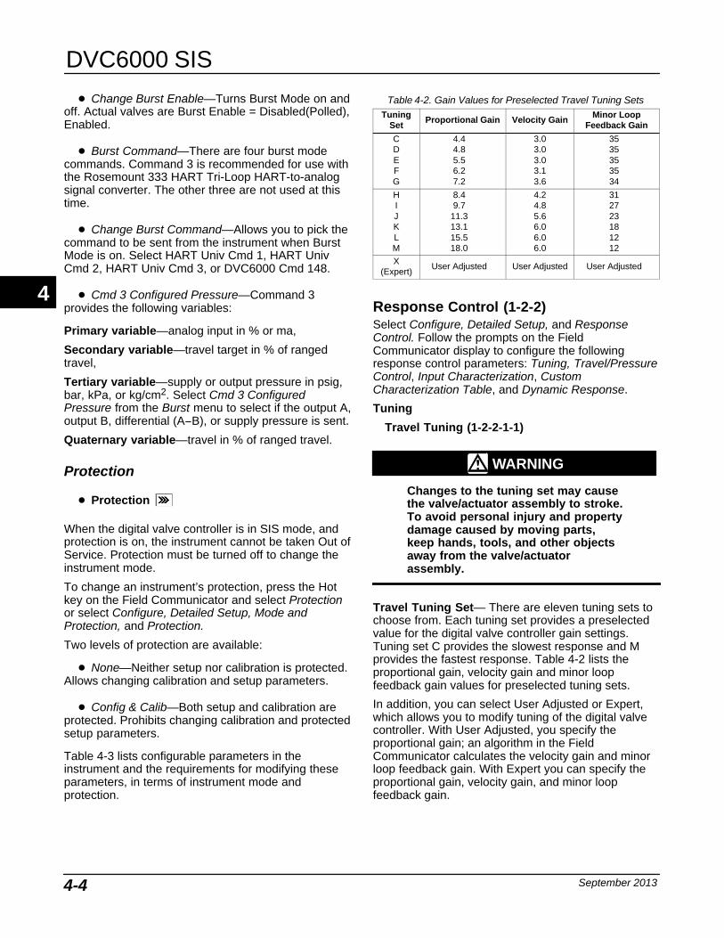
DVC6000 SIS
September 20134-4
� Change Burst Enable—Turns Burst Mode on andoff. Actual valves are Burst Enable = Disabled(Polled),Enabled.
� Burst Command—There are four burst modecommands. Command 3 is recommended for use withthe Rosemount 333 HART Tri-Loop HART-to-analogsignal converter. The other three are not used at thistime.
� Change Burst Command—Allows you to pick thecommand to be sent from the instrument when BurstMode is on. Select HART Univ Cmd 1, HART UnivCmd 2, HART Univ Cmd 3, or DVC6000 Cmd 148.
� Cmd 3 Configured Pressure—Command 3provides the following variables:
Primary variable—analog input in % or ma,
Secondary variable—travel target in % of rangedtravel,
Tertiary variable—supply or output pressure in psig,bar, kPa, or kg/cm2. Select Cmd 3 ConfiguredPressure from the Burst menu to select if the output A,output B, differential (A−B), or supply pressure is sent.
Quaternary variable—travel in % of ranged travel.
Protection
� Protection
When the digital valve controller is in SIS mode, andprotection is on, the instrument cannot be taken Out ofService. Protection must be turned off to change theinstrument mode.
To change an instrument’s protection, press the Hotkey on the Field Communicator and select Protectionor select Configure, Detailed Setup, Mode andProtection, and Protection.
Two levels of protection are available:
� None—Neither setup nor calibration is protected.Allows changing calibration and setup parameters.
� Config & Calib—Both setup and calibration areprotected. Prohibits changing calibration and protectedsetup parameters.
Table 4-3 lists configurable parameters in theinstrument and the requirements for modifying theseparameters, in terms of instrument mode andprotection.
Table 4-2. Gain Values for Preselected Travel Tuning SetsTuning
SetProportional Gain Velocity Gain Minor Loop
Feedback Gain
CDEFG
4.44.85.56.27.2
3.03.03.03.13.6
3535353534
HIJKLM
8.49.7
11.313.115.518.0
4.24.85.66.06.06.0
312723181212
X(Expert)
User Adjusted User Adjusted User Adjusted
Response Control (1-2-2)Select Configure, Detailed Setup, and ResponseControl. Follow the prompts on the FieldCommunicator display to configure the followingresponse control parameters: Tuning, Travel/PressureControl, Input Characterization, CustomCharacterization Table, and Dynamic Response.
Tuning
Travel Tuning (1-2-2-1-1)
WARNING
Changes to the tuning set may causethe valve/actuator assembly to stroke.To avoid personal injury and propertydamage caused by moving parts,keep hands, tools, and other objectsaway from the valve/actuatorassembly.
Travel Tuning Set— There are eleven tuning sets tochoose from. Each tuning set provides a preselectedvalue for the digital valve controller gain settings.Tuning set C provides the slowest response and Mprovides the fastest response. Table 4-2 lists theproportional gain, velocity gain and minor loopfeedback gain values for preselected tuning sets.
In addition, you can select User Adjusted or Expert,which allows you to modify tuning of the digital valvecontroller. With User Adjusted, you specify theproportional gain; an algorithm in the FieldCommunicator calculates the velocity gain and minorloop feedback gain. With Expert you can specify theproportional gain, velocity gain, and minor loopfeedback gain.
4
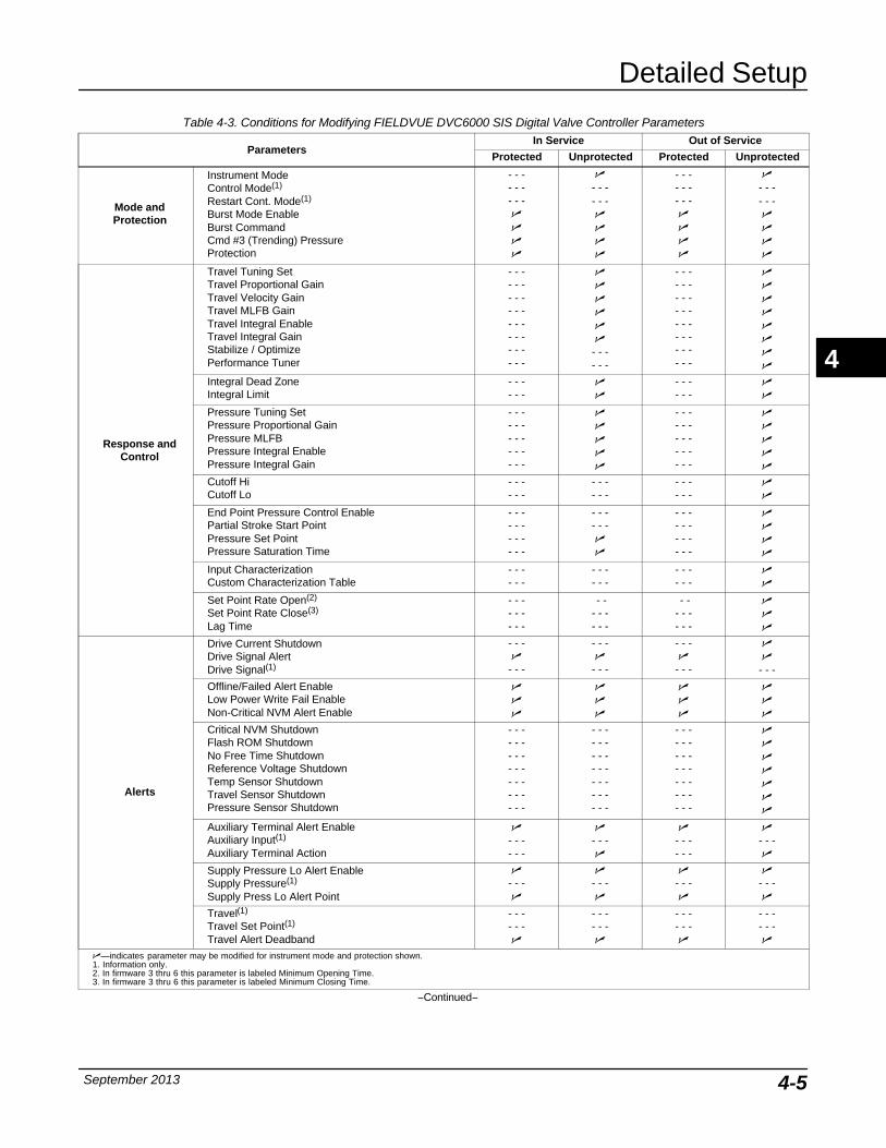
Detailed Setup
September 2013 4-5
Table 4-3. Conditions for Modifying FIELDVUE DVC6000 SIS Digital Valve Controller Parameters
ParametersIn Service Out of Service
Protected Unprotected Protected Unprotected
Mode andProtection
Instrument ModeControl Mode(1)
Restart Cont. Mode(1)
Burst Mode EnableBurst Command Cmd #3 (Trending) PressureProtection
- - -- - -- - -�
�
�
�
�
- - -- - -�
�
�
�
- - -- - -- - -�
�
�
�
�
- - -- - -�
�
�
�
Response andControl
Travel Tuning SetTravel Proportional GainTravel Velocity GainTravel MLFB GainTravel Integral EnableTravel Integral GainStabilize / OptimizePerformance Tuner
- - -- - -- - -- - -- - -- - -- - -- - -
�
�
�
�
�
�
- - -- - -
- - -- - -- - -- - -- - -- - -- - -- - -
�
�
�
�
�
�
�
�
Integral Dead ZoneIntegral Limit
- - -- - -
�
�
- - -- - -
�
�
Pressure Tuning SetPressure Proportional GainPressure MLFBPressure Integral EnablePressure Integral Gain
- - -- - -- - -- - -- - -
�
�
�
�
�
- - -- - -- - -- - -- - -
�
�
�
�
�
Cutoff HiCutoff Lo
- - -- - -
- - -- - -
- - -- - -
�
�
End Point Pressure Control EnablePartial Stroke Start PointPressure Set PointPressure Saturation Time
- - -- - -- - -- - -
- - -- - -�
�
- - -- - -- - -- - -
�
�
�
�
Input CharacterizationCustom Characterization Table
- - -- - -
- - -- - -
- - -- - -
�
�
Set Point Rate Open(2)
Set Point Rate Close(3)
Lag Time
- - -- - -- - -
- -- - -- - -
- -- - -- - -
�
�
�
Alerts
Drive Current ShutdownDrive Signal AlertDrive Signal(1)
- - -�
- - -
- - -�
- - -
- - -�
- - -
�
�
- - -
Offline/Failed Alert EnableLow Power Write Fail EnableNon-Critical NVM Alert Enable
�
�
�
�
�
�
�
�
�
�
�
�
Critical NVM Shutdown Flash ROM Shutdown No Free Time ShutdownReference Voltage ShutdownTemp Sensor ShutdownTravel Sensor ShutdownPressure Sensor Shutdown
- - -- - -- - -- - -- - -- - -- - -
- - -- - -- - -- - -- - -- - -- - -
- - -- - -- - -- - -- - -- - -- - -
�
�
�
�
�
�
�
Auxiliary Terminal Alert EnableAuxiliary Input(1)
Auxiliary Terminal Action
�
- - -- - -
�
- - -�
�
- - -- - -
�
- - -�
Supply Pressure Lo Alert EnableSupply Pressure(1)
Supply Press Lo Alert Point
�
- - -�
�
- - -�
�
- - -�
�
- - -�
Travel(1)
Travel Set Point(1)
Travel Alert Deadband
- - -- - -�
- - -- - -�
- - -- - -�
- - -- - -�
�—indicates parameter may be modified for instrument mode and protection shown.1. Information only.2. In firmware 3 thru 6 this parameter is labeled Minimum Opening Time.3. In firmware 3 thru 6 this parameter is labeled Minimum Closing Time.
−Continued−
4
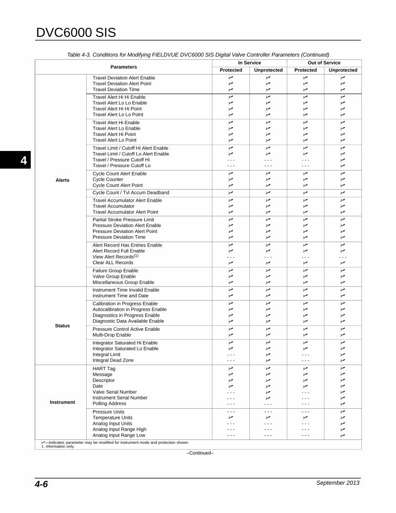
DVC6000 SIS
September 20134-6
Table 4-3. Conditions for Modifying FIELDVUE DVC6000 SIS Digital Valve Controller Parameters (Continued)
ParametersIn Service Out of Service
Protected Unprotected Protected Unprotected
Alerts
Travel Deviation Alert EnableTravel Deviation Alert PointTravel Deviation Time
�
�
�
�
�
�
�
�
�
�
�
�
Travel Alert Hi Hi EnableTravel Alert Lo Lo EnableTravel Alert Hi Hi Point Travel Alert Lo Lo Point
�
�
�
�
�
�
�
�
�
�
�
�
�
�
�
�
Travel Alert Hi EnableTravel Alert Lo EnableTravel Alert Hi Point Travel Alert Lo Point
�
�
�
�
�
�
�
�
�
�
�
�
�
�
�
�
Travel Limit / Cutoff Hi Alert EnableTravel Limit / Cutoff Lo Alert EnableTravel / Pressure Cutoff HiTravel / Pressure Cutoff Lo
�
�
- - -- - -
�
�
- - -- - -
�
�
- - -- - -
�
�
�
�
Cycle Count Alert EnableCycle CounterCycle Count Alert Point
�
�
�
�
�
�
�
�
�
�
�
�
Cycle Count / Tvl Accum Deadband � � � �
Travel Accumulator Alert EnableTravel AccumulatorTravel Accumulator Alert Point
�
�
�
�
�
�
�
�
�
�
�
�
Partial Stroke Pressure LimitPressure Deviation Alert EnablePressure Deviation Alert PointPressure Deviation Time
�
�
�
�
�
�
�
�
�
�
�
�
�
�
�
�
Alert Record Has Entries EnableAlert Record Full EnableView Alert Records(1)
Clear ALL Records
�
�
- - -�
�
�
- - -�
�
�
- - -�
�
�
- - -�
Failure Group EnableValve Group EnableMiscellaneous Group Enable
�
�
�
�
�
�
�
�
�
�
�
�
Status
Instrument Time Invalid EnableInstrument Time and Date
�
�
�
�
�
�
�
�
Calibration in Progress EnableAutocalibration in Progress EnableDiagnostics in Progress EnableDiagnostic Data Available Enable
�
�
�
�
�
�
�
�
�
�
�
�
�
�
�
�
Pressure Control Active EnableMulti-Drop Enable
�
�
�
�
�
�
�
�
Integrator Saturated Hi EnableIntegrator Saturated Lo EnableIntegral LimitIntegral Dead Zone
�
�
- - -- - -
�
�
�
�
�
�
- - -- - -
�
�
�
�
Instrument
HART TagMessageDescriptorDateValve Serial NumberInstrument Serial NumberPolling Address
�
�
�
�
- - -- - -- - -
�
�
�
�
�
�
- - -
�
�
�
�
- - -- - -- - -
�
�
�
�
�
�
�
Pressure Units Temperature UnitsAnalog Input UnitsAnalog Input Range HighAnalog Input Range Low
- - -�
- - -- - -- - -
- - -�
- - -- - -- - -
- - -�
- - -- - -- - -
�
�
�
�
�
�—indicates parameter may be modified for instrument mode and protection shown.1. Information only.
−Continued−
4
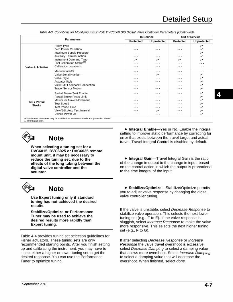
Detailed Setup
September 2013 4-7
Table 4-3. Conditions for Modifying FIELDVUE DVC6000 SIS Digital Valve Controller Parameters (Continued)
ParametersIn Service Out of Service
Protected Unprotected Protected Unprotected
Valve & Actuator
Relay TypeZero Power ConditionMaximum Supply PressureAuxiliary Terminal ActionInstrument Date and TimeLast Calibration Status(1)
Calibration Location(1)
- - -- - -- - -- - -�
- - -- - -
- - -- - -- - -- - -�
- - -- - -
- - -- - -- - -- - -�
- - -- - -
�
�
�
�
�
- - -- - -
Manufacturer(1)
Valve Serial NumberValve StyleActuator StyleView/Edit Feedback ConnectionTravel Sensor Motion
- - -- - -- - -- - -- - -- - -
- - -�
- - -- - -- - -- - -
- - -- - -- - -- - -- - -- - -
- - -�
�
�
�
�
SIS / PartialStroke
Partial Stroke Test EnablePartial Stroke Press LimitMaximum Travel MovementTest SpeedTest Pause TimeView/Edit Auto Test IntervalDevice Power Up
- - -- - -- - -- - -- - -- - -- - -
- - -- - -- - -- - -- - -�
- - -
- - -- - -- - -- - -- - -- - -- - -
�
�
�
�
�
�
�
�—indicates parameter may be modified for instrument mode and protection shown.1. Information only.
NoteWhen selecting a tuning set for aDVC6015, DVC6025 or DVC6035 remotemount unit, it may be necessary toreduce the tuning set, due to theeffects of the long tubing between thedigital valve controller and theactuator.
NoteUse Expert tuning only if standardtuning has not achieved the desiredresults.
Stabilize/Optimize or PerformanceTuner may be used to achieve thedesired results more rapidly thanExpert tuning.
Table 4-4 provides tuning set selection guidelines forFisher actuators. These tuning sets are onlyrecommended starting points. After you finish settingup and calibrating the instrument, you may have toselect either a higher or lower tuning set to get thedesired response. You can use the PerformanceTuner to optimize tuning.
� Integral Enable—Yes or No. Enable the integralsetting to improve static performance by correcting forerror that exists between the travel target and actualtravel. Travel Integral Control is disabled by default.
� Integral Gain—Travel Integral Gain is the ratioof the change in output to the change in input, basedon the control action in which the output is proportionalto the time integral of the input.
� Stabilize/Optimize—Stabilize/Optimize permitsyou to adjust valve response by changing the digitalvalve controller tuning.
If the valve is unstable, select Decrease Response tostabilize valve operation. This selects the next lowertuning set (e.g., F to E). If the valve response issluggish, select Increase Response to make the valvemore responsive. This selects the next higher tuningset (e.g., F to G).
If after selecting Decrease Response or IncreaseResponse the valve travel overshoot is excessive,select Decrease Damping to select a damping valuethat allows more overshoot. Select Increase Dampingto select a damping value that will decrease theovershoot. When finished, select done.
4
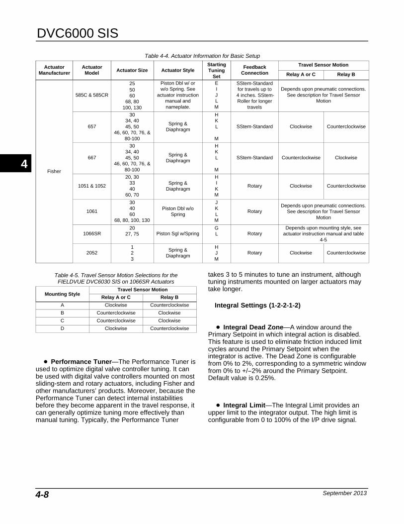
DVC6000 SIS
September 20134-8
Table 4-4. Actuator Information for Basic Setup
ActuatorManufacturer
ActuatorModel Actuator Size Actuator Style
StartingTuning
Set
FeedbackConnection
Travel Sensor Motion
Relay A or C Relay B
Fisher
585C & 585CR
255060
68, 80100, 130
Piston Dbl w/ orw/o Spring. See
actuator instructionmanual andnameplate.
EIJLM
SStem-Standardfor travels up to
4 inches. SStem-Roller for longer
travels
Depends upon pneumatic connections.See description for Travel Sensor
Motion
657
3034, 4045, 50
46, 60, 70, 76, &80-100
Spring &Diaphragm
HKL
M
SStem-Standard Clockwise Counterclockwise
667
3034, 4045, 50
46, 60, 70, 76, &80-100
Spring &Diaphragm
HKL
M
SStem-Standard Counterclockwise Clockwise
1051 & 1052
20, 303340
60, 70
Spring &Diaphragm
HIKM
Rotary Clockwise Counterclockwise
1061
304060
68, 80, 100, 130
Piston Dbl w/oSpring
JKLM
RotaryDepends upon pneumatic connections.
See description for Travel SensorMotion
1066SR20
27, 75 Piston Sgl w/SpringGL Rotary
Depends upon mounting style, seeactuator instruction manual and table
4-5
2052123
Spring &Diaphragm
HJM
Rotary Clockwise Counterclockwise
Table 4-5. Travel Sensor Motion Selections for theFIELDVUE DVC6030 SIS on 1066SR Actuators
Mounting StyleTravel Sensor Motion
Relay A or C Relay B
A Clockwise Counterclockwise
B Counterclockwise Clockwise
C Counterclockwise Clockwise
D Clockwise Counterclockwise
� Performance Tuner—The Performance Tuner isused to optimize digital valve controller tuning. It canbe used with digital valve controllers mounted on mostsliding-stem and rotary actuators, including Fisher andother manufacturers’ products. Moreover, because thePerformance Tuner can detect internal instabilitiesbefore they become apparent in the travel response, itcan generally optimize tuning more effectively thanmanual tuning. Typically, the Performance Tuner
takes 3 to 5 minutes to tune an instrument, althoughtuning instruments mounted on larger actuators maytake longer.
Integral Settings (1-2-2-1-2)
� Integral Dead Zone—A window around thePrimary Setpoint in which integral action is disabled.This feature is used to eliminate friction induced limitcycles around the Primary Setpoint when theintegrator is active. The Dead Zone is configurablefrom 0% to 2%, corresponding to a symmetric windowfrom 0% to +/−2% around the Primary Setpoint.Default value is 0.25%.
� Integral Limit—The Integral Limit provides anupper limit to the integrator output. The high limit isconfigurable from 0 to 100% of the I/P drive signal.
4
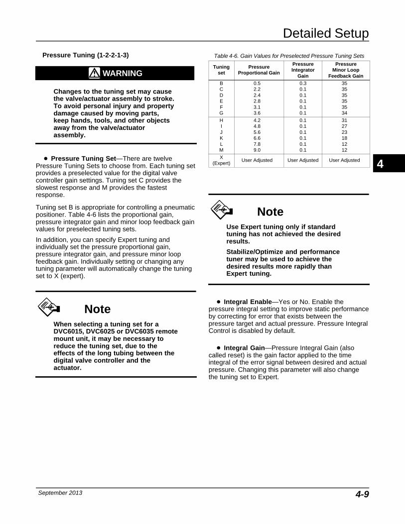
Detailed Setup
September 2013 4-9
Pressure Tuning (1-2-2-1-3)
WARNING
Changes to the tuning set may causethe valve/actuator assembly to stroke.To avoid personal injury and propertydamage caused by moving parts,keep hands, tools, and other objectsaway from the valve/actuatorassembly.
� Pressure Tuning Set—There are twelvePressure Tuning Sets to choose from. Each tuning setprovides a preselected value for the digital valvecontroller gain settings. Tuning set C provides theslowest response and M provides the fastestresponse.
Tuning set B is appropriate for controlling a pneumaticpositioner. Table 4-6 lists the proportional gain,pressure integrator gain and minor loop feedback gainvalues for preselected tuning sets.
In addition, you can specify Expert tuning andindividually set the pressure proportional gain,pressure integrator gain, and pressure minor loopfeedback gain. Individually setting or changing anytuning parameter will automatically change the tuningset to X (expert).
NoteWhen selecting a tuning set for aDVC6015, DVC6025 or DVC6035 remotemount unit, it may be necessary toreduce the tuning set, due to theeffects of the long tubing between thedigital valve controller and theactuator.
Table 4-6. Gain Values for Preselected Pressure Tuning Sets
Tuningset
PressureProportional Gain
PressureIntegrator
Gain
PressureMinor Loop
Feedback GainBCDEFG
0.52.22.42.83.13.6
0.30.10.10.10.10.1
353535353534
HIJKLM
4.24.85.66.67.89.0
0.10.10.10.10.10.1
312723181212
X(Expert)
User Adjusted User Adjusted User Adjusted
NoteUse Expert tuning only if standardtuning has not achieved the desiredresults.
Stabilize/Optimize and performancetuner may be used to achieve thedesired results more rapidly thanExpert tuning.
� Integral Enable—Yes or No. Enable thepressure integral setting to improve static performanceby correcting for error that exists between thepressure target and actual pressure. Pressure IntegralControl is disabled by default.
� Integral Gain—Pressure Integral Gain (alsocalled reset) is the gain factor applied to the timeintegral of the error signal between desired and actualpressure. Changing this parameter will also changethe tuning set to Expert.
4
DVC6000 SIS
September 20134-10
Travel/Pressure Control
Tvl/Press Cutoffs (1-2-2-2-1)
� Cutoff Hi—Defines the high cutoff point for thetravel in percent (%) of ranged input current.
� Cutoff Lo—Defines the low cutoff point for thetravel set point.
� Change Cutoffs—Allows you to set Cutoff Hi andCutoff Lo. When a cutoff is set the correspondingtravel or pressure limit is disabled.
Travel cutoffs are adjustable when the DVC6000 SISis operating with a 4-20 mA current input. The SetupWizard automatically sets travel cutoffs at 50%,making the DVC6000 SIS work like an on-off device.At current levels from 4.0 to 11.99 mA, the DVC6000SIS will provide minimum output pressure, and at 12to 20 mA, the DVC6000 SIS will provide full outputpressure.
You can customize valve response to the controlsignal by changing the travel cutoffs. For example, it ispossible to have the valve throttle between 10 and90% travel, but work as an on-off valve between 0% to10% and 90% to 100% travel. The user now has astandard throttling control valve between 10% and90% travel. Outside of this range, the valve will moveto its travel extreme (0% or 100%).
NoteIf you run the Setup Wizard afteradjusting the Travel Cutoffs, they willrevert back to the default values. Youwill need to reset the Travel Cutoffs tothe desired settings.
NoteThe partial stroke test cannot beconducted by the Field Communicatoror ValveLink software while the digitalvalve controller is in its normal travelcontrol mode (with adjustable cutoffsset to a different value than thedefault).
WARNING
Using the auxiliary terminal (pushbutton) for partial stroke testing whilethe DVC6000 SIS digital valvecontroller is in point-to-point modemay cause changes in outputpressure and travel, resulting inprocess instability. Depending on theapplication, these changes may upsetthe process, which may result inpersonal injury or property damage.
If the auxiliary terminal button ispressed for more than 3 seconds, butless than 5 seconds, the digital valvecontroller will drive the valve from itsexisting travel position to 100% travelcondition for a fail close valve (or 0%travel for a fail open valve) andperform the partial stroke test. Oncethe partial stroke test is completed,the digital valve controller will bringthe valve back to its original travel,corresponding to the control setpoint.
NoteIn a typical 0-24 VDC de-energize-to-trip operating system, a digital valvecontroller with the single-acting directrelay will provide full output pressureto port A when 24 VDC is applied, andminimum (near 0) output pressure toport A when 0 VDC is applied. With thesingle-acting direct relay, there wouldbe no output pressure from port B.
Other configurations of the relay areavailable (see table 3-2). An example ofthis flexibility is the use of asingle-acting reverse relay that willsupply full pressure output at 0 VDCinput. This configuration can be usefulto provide the benefits of Partial ValveStroke Diagnostics but minimize thespurious trip rate (the power to thedigital valve controller can be lostwithout tripping the valve), but wouldonly be recommended when asolenoid is provided to take the valveto the safe position
4
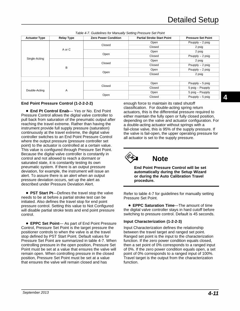
Detailed Setup
September 2013 4-11
Table 4-7. Guidelines for Manually Setting Pressure Set PointActuator Type Relay Type Zero Power Condition Partial Stroke Start Point Pressure Set Point
Single-Acting
A or C
ClosedOpen Psupply − 2 psig
Closed 2 psig
OpenOpen 2 psig
Closed Psupply − 2 psig
B
ClosedOpen 2 psig
Closed Psupply − 2 psig
OpenOpen Psupply − 2 psig
Closed 2 psig
Double-Acting A
ClosedOpen Psupply − 5 psig
Closed 5 psig − Psupply
OpenOpen 5 psig − Psupply
Closed Psupply − 5 psig
End Point Pressure Control (1-2-2-2-2)
� End Pt Control Enab— Yes or No. End PointPressure Control allows the digital valve controller topull back from saturation of the pneumatic output afterreaching the travel extreme. Rather than having theinstrument provide full supply pressure (saturation)continuously at the travel extreme, the digital valvecontroller switches to an End Point Pressure Controlwhere the output pressure (pressure controller setpoint) to the actuator is controlled at a certain value.This value is configured through Pressure Set Point.Because the digital valve controller is constantly incontrol and not allowed to reach a dormant orsaturated state, it is constantly testing its ownpneumatic system. If there is an output pressuredeviation, for example, the instrument will issue analert. To assure there is an alert when an outputpressure deviation occurs, set up the alert asdescribed under Pressure Deviation Alert.
� PST Start Pt—Defines the travel stop the valveneeds to be at before a partial stroke test can beinitiated. Also defines the travel stop for end pointpressure control. Setting this value to Not Configuredwill disable partial stroke tests and end point pressurecontrol.
� EPPC Set Point— As part of End Point PressureControl, Pressure Set Point is the target pressure thepositioner controls to when the valve is at the travelstop defined by PST Start Point. Default values forPressure Set Point are summarized in table 4-7. Whencontrolling pressure in the open position, Pressure SetPoint must be set at a value that ensures the valve willremain open. When controlling pressure in the closedposition, Pressure Set Point must be set at a valuethat ensures the valve will remain closed and has
enough force to maintain its rated shutoffclassification. For double-acting spring returnactuators, this is the differential pressure required toeither maintain the fully open or fully closed position,depending on the valve and actuator configuration. Fora double-acting actuator without springs with afail-close valve, this is 95% of the supply pressure. Ifthe valve is fail-open, the upper operating pressure forall actuator is set to the supply pressure.
NoteEnd Point Pressure Control will be setautomatically during the Setup Wizardor during the Auto Calibration Travelprocedure.
Refer to table 4-7 for guidelines for manually settingPressure Set Point.
� EPPC Saturation Time—The amount of timethe digital valve controller stays in hard cutoff beforeswitching to pressure control. Default is 45 seconds.
Input Characterization (1-2-2-3)
Input Characterization defines the relationshipbetween the travel target and ranged set point.Ranged set point is the input to the characterizationfunction. If the zero power condition equals closed,then a set point of 0% corresponds to a ranged inputof 0%. If the zero power condition equals open, a setpoint of 0% corresponds to a ranged input of 100%.Travel target is the output from the characterizationfunction.
4
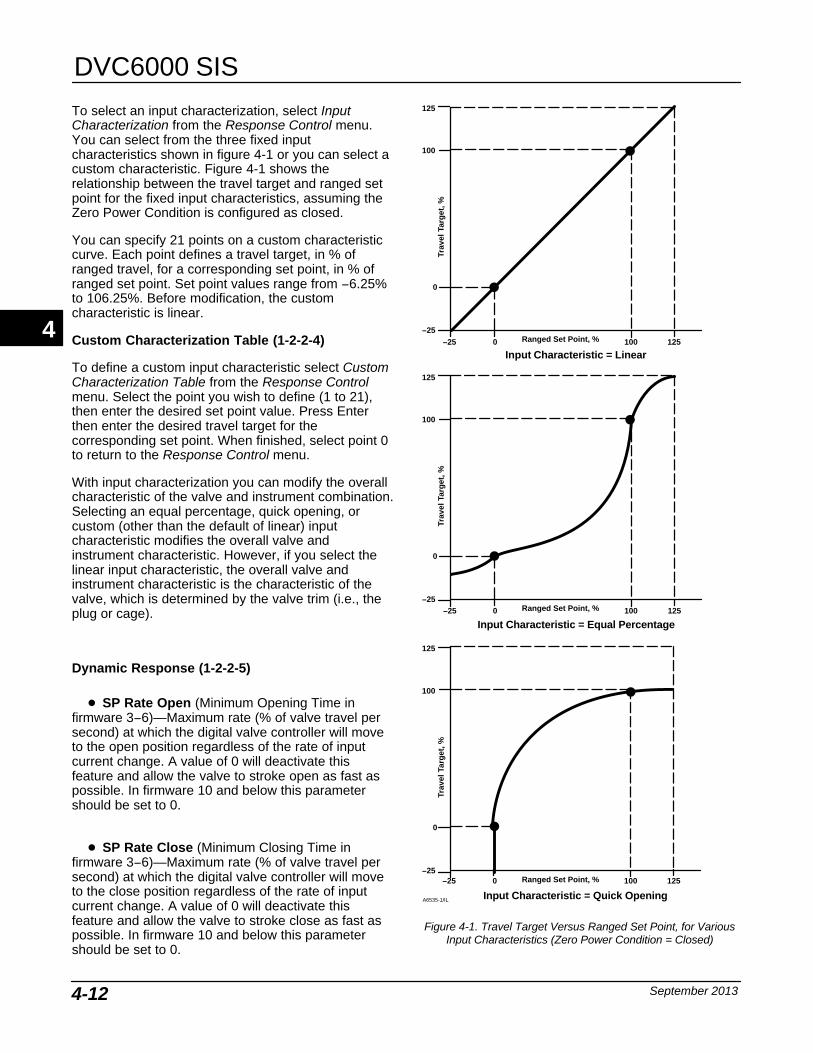
DVC6000 SIS
September 20134-12
To select an input characterization, select InputCharacterization from the Response Control menu.You can select from the three fixed inputcharacteristics shown in figure 4-1 or you can select acustom characteristic. Figure 4-1 shows therelationship between the travel target and ranged setpoint for the fixed input characteristics, assuming theZero Power Condition is configured as closed.
You can specify 21 points on a custom characteristiccurve. Each point defines a travel target, in % ofranged travel, for a corresponding set point, in % ofranged set point. Set point values range from −6.25%to 106.25%. Before modification, the customcharacteristic is linear.
Custom Characterization Table (1-2-2-4)
To define a custom input characteristic select CustomCharacterization Table from the Response Controlmenu. Select the point you wish to define (1 to 21),then enter the desired set point value. Press Enterthen enter the desired travel target for thecorresponding set point. When finished, select point 0to return to the Response Control menu.
With input characterization you can modify the overallcharacteristic of the valve and instrument combination.Selecting an equal percentage, quick opening, orcustom (other than the default of linear) inputcharacteristic modifies the overall valve andinstrument characteristic. However, if you select thelinear input characteristic, the overall valve andinstrument characteristic is the characteristic of thevalve, which is determined by the valve trim (i.e., theplug or cage).
Dynamic Response (1-2-2-5)
� SP Rate Open (Minimum Opening Time infirmware 3−6)—Maximum rate (% of valve travel persecond) at which the digital valve controller will moveto the open position regardless of the rate of inputcurrent change. A value of 0 will deactivate thisfeature and allow the valve to stroke open as fast aspossible. In firmware 10 and below this parametershould be set to 0.
� SP Rate Close (Minimum Closing Time infirmware 3−6)—Maximum rate (% of valve travel persecond) at which the digital valve controller will moveto the close position regardless of the rate of inputcurrent change. A value of 0 will deactivate thisfeature and allow the valve to stroke close as fast aspossible. In firmware 10 and below this parametershould be set to 0.
Trav
el T
arg
et, %
Ranged Set Point, %−25 0 125100
−25 0 125100
−25 0 125100
Input Characteristic = Linear
Input Characteristic = Equal Percentage
Input Characteristic = Quick Opening
100
0
−25
125
Trav
el T
arg
et, %
100
0
−25
125
Ranged Set Point, %
Trav
el T
arg
et, %
100
0
−25
125
Ranged Set Point, %
A6535-1/IL
Figure 4-1. Travel Target Versus Ranged Set Point, for VariousInput Characteristics (Zero Power Condition = Closed)
4
Detailed Setup
September 2013 4-13
NoteLag Time is available in firmware 7, 9,10, and 11.
� Lag Time—Slows the response of the digitalvalve controller. A value ranging from 0.2 to 10.0 canbe used for noisy or fast processes to improve closedloop process control. Entering a value of 0.0 willdeactivate the lag filter. In firmware 7, 9, and 10 thisparameter should be set to 0.
Alert Setup (1-2-3)The following menus are available for configuringalerts and shutdowns. Items on the menus may bechanged with the instrument In Service. Protectiondoes not need to be removed (no need to set toNone). Alerts are not processed when a diagnostic isin progress. Select Configure, Detailed Setup, andAlert Setup. Follow the prompts on the FieldCommunicator display to configure the followingAlerts: Electronic Alerts, Sensor Alerts, EnvironmentAlerts, Travel Alerts, Travel History Alerts, SIS Alerts,and Alert Record.
NoteThe Alerts section covers alerts andshutdowns. An alert, if enabled, canprovide information on operation andperformance issues. A shutdown, ifenabled, and upon the occurrence ofthe associated failure alert, will causethe instrument air output to go to theZero Power Condition as per figure4-6. It will remain latched in thatcondition until power to theinstrument is cycled and the failurealert has cleared. While in shutdowncondition the instrument will remainpowered up and able to communicatevia HART.
Electronics Alerts (1-2-3-1)
� Drive Current Shutdown— Describes thestatus of I/P current; should the current fail, the digitalvalve controller will drive the output to its safe
condition. Drive Current Shutdown is part of “Self Testshutdown”. Default is not enabled.
Drive Signal Alert (1-2-3-1-2)
Drive Signal Alert checks the drive signal andcalibrated travel. If one of the following conditionsexists for more than 20 seconds, the Drive Signal Alertis set.
For the case where Zero Power Condition is definedas closed:
Drive Signal < 10% and Calibrated Travel > 3%
Drive Signal > 90% and Calibrated Travel < 97%
For the case where Zero Power Condition is definedas open:
Drive Signal < 10% and Calibrated Travel < 97%
Drive Signal > 90% and Calibrated Travel > 3%
� Drive Signal Alert Enable—Yes or No. DriveSignal Alert Enable activates checking of therelationship between the Drive Signal and thecalibrated travel.
� Drive Signal—Shows the value of the instrumentdrive signal in % (percent) of maximum drive.
Processor Impaired Alerts (1-2-3-1-3)
� Offline/Failed Alert Enable—If enabled, set whenthe device is in a failed state and not controlling theinput.
� Low Power Write Alert Enable—When enabled,an alert is generated if a write to the instrument isattempted and fails when the loop current is less than3.5 mA.
� Non-Critical NVM Alert Enable—When enabled,an alert is generated whenever there is a failureassociated with non-critical NVM (non-volatilememory). Default is not enabled.
� Critical NVM Shutdown—When enabled, theinstrument shuts down whenever there is a failureassociated with critical NVM (non-volatile memory).Default is not enabled.
� Flash ROM Shutdown—When enabled, theinstrument shuts down whenever there is a failureassociated with flash ROM (read only memory).Default is not enabled.
� No Free Time Shutdown—When enabled, theinstrument shuts down whenever there is a failureassociated with No Free Time. Default is not enabled.
4
DVC6000 SIS
September 20134-14
� Reference Voltage Shutdown—When enabled,the instrument shuts down whenever there is a failureassociated with the internal voltage reference. Defaultis not enabled.
Sensor Alerts (1-2-3-2)
� Travel Sensor Shutdown—When enabled, theinstrument shuts down whenever there is a failureassociated with the travel sensor. Default is notenabled.
� Temp Sensor Shutdown—When enabled, theinstrument shuts down whenever there is a failureassociated with the temperature sensor. Default is notenabled.
� Pressure Sensor Shutdown—When enabled,the instrument shuts down whenever there is a failureassociated with the pressure sensor. Default is notenabled.
Environment Alerts (1-2-3-3)
Auxiliary Terminal Alert (1-2-3-3-1)
� Auxiliary Terminal Alert Enable—Yes or No.When enabled, the auxiliary terminal acts as an alertactivation.
� Auxiliary Input—The auxiliary input of the digitalvalve controller can be configured to be used indifferent ways. The default configuration allows apre-configured partial stroke test to be initiated byshorting the aux terminals together, such as with theuse of an appropriately connected local pushbuttonswitch. It can also be configured to enable an alert thatwill be generated when a switch connected to the Auxterminals is either “open” or “closed”. The thirdconfiguration option is for the Aux terminals to be usedwith the LCP100. In this configuration, the partialstroke test is initiated using the LCP100, and the AuxInput alert is not available.
� Auxiliary Terminal Action— Can be Disabled,Alert on Open or Close Contact, SIS Local ControlPanel or Push Button Partial Stroke Test. If theLCP100 is not selected, the default is Partial StrokeTest. If the LCP100 is selected during Setup Wizard orenabled in Detailed Setup as Auxiliary Terminal Action− SIS Local Control Panel, the following parameterswill be automatically set under Travel Alerts:
Hi Hi / Lo Lo Enable − YESLo Lo Point (%) − 1Hi Hi Point (%) − 99DVC Power Up − Manual Reset
Supply Pressure Lo Alert (1-2-3-3-2)
� Supply Pressure Lo Alert Enable—Whenenabled, the instrument sends an alert when thesupply pressure falls below the supply pressure alertpoint.
� Supply—Displays the instrument supply pressurein psi, bar, kPa, or kg/cm2.
� Supply Pressure Lo Alert Point— When thesupply pressure falls below the supply pressure alertpoint, the supply pressure alert is active. To disablethe supply pressure alert, set Supply Press Alert Pointto zero.
� Loop Current Validation Enable—Whenenabled, the instrument shuts down whenever there isa failure associated with the measured loop currentbeing out-of-range.
Travel Alerts (1-2-3-4)
� Travel—Travel displays the actual position of thevalve in percent (%) of calibrated travel.
� Set Point—Travel Set Point is the input to thecharacterization function.
� Travel Alert DB—Travel Alert Deadband is thetravel, in percent (%) of ranged travel, required toclear a travel alert, once it has been set. Thedeadband applies to both Travel Alert Hi/Lo and TravelAlert Hi Hi/Lo Lo. See figure 4-2.
Travel Deviation Alert (1-2-3-4-4)
If the difference between the travel target and theactual target exceeds the Travel Deviation Alert Pointfor more than the Travel Deviation Time, the TravelDeviation Alert is set. It remains set until the differencebetween the travel target and the actual travel is lessthan the Travel Deviation Alert Point minus the TravelAlert Deadband.
� Travel Deviation Alert Enable—Select Yes or No.When enabled, checks the difference between thetravel target and the actual travel.
� Travel Deviation Alert Point—The alert point forthe difference, expressed in percent (%), between thetravel target and the actual travel. When the differenceexceeds the alert point for more than the TravelDeviation Time, the Travel Deviation Alert is set.Default value is 5%.
� Travel Deviation Time—The time, in seconds,that the travel deviation must exceed the TravelDeviation Alert Point before the alert is set. Defaultvalue is 10 seconds.
4
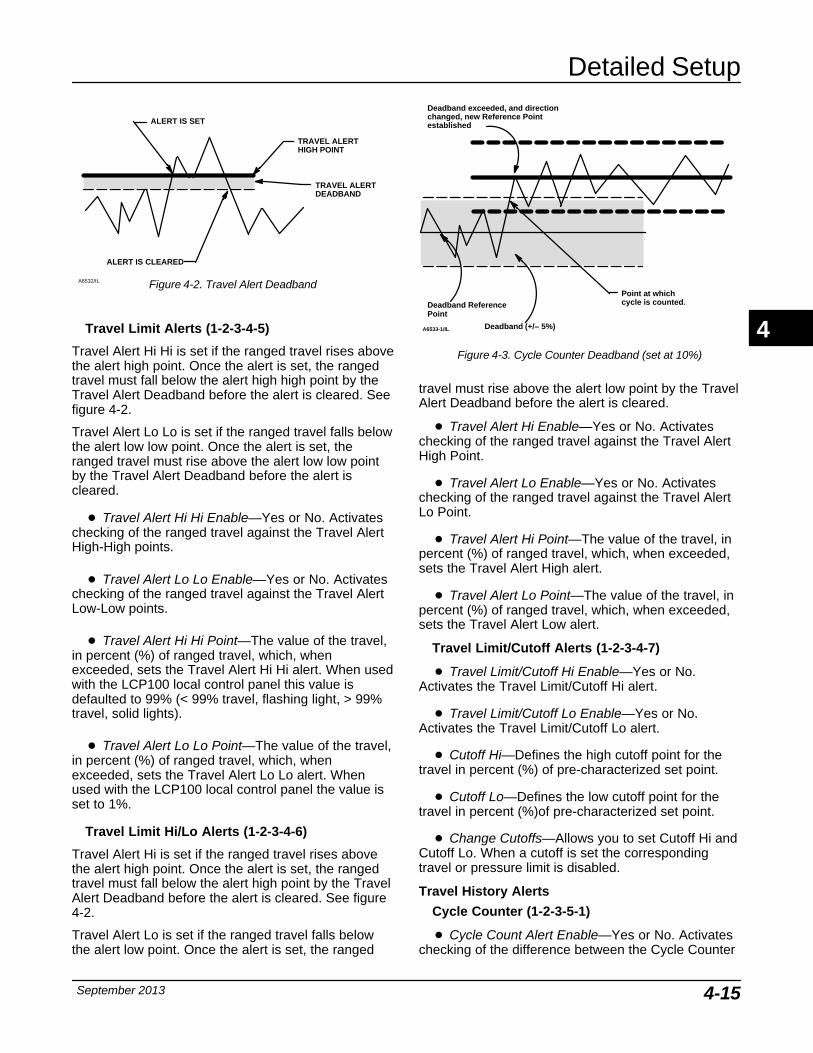
Detailed Setup
September 2013 4-15
ALERT IS CLEARED
ALERT IS SET
TRAVEL ALERTHIGH POINT
TRAVEL ALERTDEADBAND
A6532/IL Figure 4-2. Travel Alert Deadband
Travel Limit Alerts (1-2-3-4-5)
Travel Alert Hi Hi is set if the ranged travel rises abovethe alert high point. Once the alert is set, the rangedtravel must fall below the alert high high point by theTravel Alert Deadband before the alert is cleared. Seefigure 4-2.
Travel Alert Lo Lo is set if the ranged travel falls belowthe alert low low point. Once the alert is set, theranged travel must rise above the alert low low pointby the Travel Alert Deadband before the alert iscleared.
� Travel Alert Hi Hi Enable—Yes or No. Activateschecking of the ranged travel against the Travel AlertHigh-High points.
� Travel Alert Lo Lo Enable—Yes or No. Activateschecking of the ranged travel against the Travel AlertLow-Low points.
� Travel Alert Hi Hi Point—The value of the travel,in percent (%) of ranged travel, which, whenexceeded, sets the Travel Alert Hi Hi alert. When usedwith the LCP100 local control panel this value isdefaulted to 99% (< 99% travel, flashing light, > 99%travel, solid lights).
� Travel Alert Lo Lo Point—The value of the travel,in percent (%) of ranged travel, which, whenexceeded, sets the Travel Alert Lo Lo alert. Whenused with the LCP100 local control panel the value isset to 1%.
Travel Limit Hi/Lo Alerts (1-2-3-4-6)
Travel Alert Hi is set if the ranged travel rises abovethe alert high point. Once the alert is set, the rangedtravel must fall below the alert high point by the TravelAlert Deadband before the alert is cleared. See figure4-2.
Travel Alert Lo is set if the ranged travel falls belowthe alert low point. Once the alert is set, the ranged
Deadband Reference
Deadband (+/− 5%)
Deadband exceeded, and directionchanged, new Reference Pointestablished
Point
Point at whichcycle is counted.
A6533-1/IL
Figure 4-3. Cycle Counter Deadband (set at 10%)
travel must rise above the alert low point by the TravelAlert Deadband before the alert is cleared.
� Travel Alert Hi Enable—Yes or No. Activateschecking of the ranged travel against the Travel AlertHigh Point.
� Travel Alert Lo Enable—Yes or No. Activateschecking of the ranged travel against the Travel AlertLo Point.
� Travel Alert Hi Point—The value of the travel, inpercent (%) of ranged travel, which, when exceeded,sets the Travel Alert High alert.
� Travel Alert Lo Point—The value of the travel, inpercent (%) of ranged travel, which, when exceeded,sets the Travel Alert Low alert.
Travel Limit/Cutoff Alerts (1-2-3-4-7)
� Travel Limit/Cutoff Hi Enable—Yes or No.Activates the Travel Limit/Cutoff Hi alert.
� Travel Limit/Cutoff Lo Enable—Yes or No.Activates the Travel Limit/Cutoff Lo alert.
� Cutoff Hi—Defines the high cutoff point for thetravel in percent (%) of pre-characterized set point.
� Cutoff Lo—Defines the low cutoff point for thetravel in percent (%)of pre-characterized set point.
� Change Cutoffs—Allows you to set Cutoff Hi andCutoff Lo. When a cutoff is set the correspondingtravel or pressure limit is disabled.
Travel History Alerts
Cycle Counter (1-2-3-5-1)
� Cycle Count Alert Enable—Yes or No. Activateschecking of the difference between the Cycle Counter
4
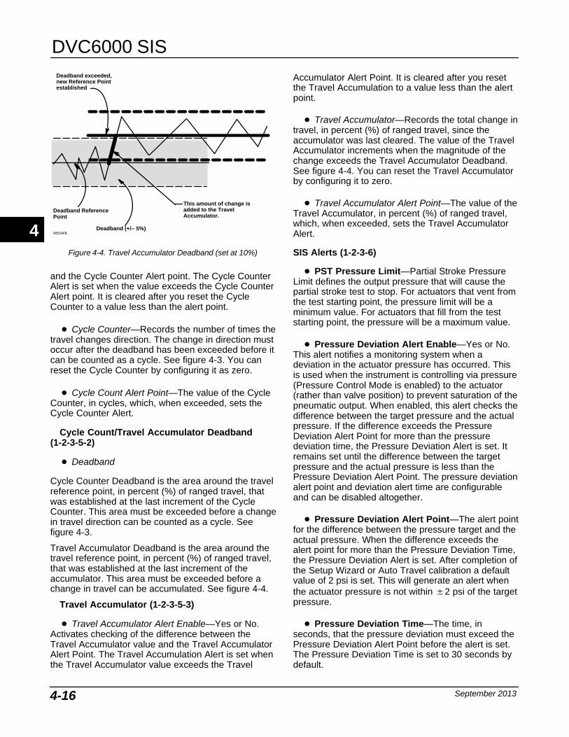
DVC6000 SIS
September 20134-16
Deadband Reference
Deadband (+/− 5%)
Deadband exceeded,new Reference Pointestablished
Point
This amount of change isadded to the TravelAccumulator.
A6534/IL
Figure 4-4. Travel Accumulator Deadband (set at 10%)
and the Cycle Counter Alert point. The Cycle CounterAlert is set when the value exceeds the Cycle CounterAlert point. It is cleared after you reset the CycleCounter to a value less than the alert point.
� Cycle Counter—Records the number of times thetravel changes direction. The change in direction mustoccur after the deadband has been exceeded before itcan be counted as a cycle. See figure 4-3. You canreset the Cycle Counter by configuring it as zero.
� Cycle Count Alert Point—The value of the CycleCounter, in cycles, which, when exceeded, sets theCycle Counter Alert.
Cycle Count/Travel Accumulator Deadband(1-2-3-5-2)
� Deadband
Cycle Counter Deadband is the area around the travelreference point, in percent (%) of ranged travel, thatwas established at the last increment of the CycleCounter. This area must be exceeded before a changein travel direction can be counted as a cycle. Seefigure 4-3.
Travel Accumulator Deadband is the area around thetravel reference point, in percent (%) of ranged travel,that was established at the last increment of theaccumulator. This area must be exceeded before achange in travel can be accumulated. See figure 4-4.
Travel Accumulator (1-2-3-5-3)
� Travel Accumulator Alert Enable—Yes or No.Activates checking of the difference between theTravel Accumulator value and the Travel AccumulatorAlert Point. The Travel Accumulation Alert is set whenthe Travel Accumulator value exceeds the Travel
Accumulator Alert Point. It is cleared after you resetthe Travel Accumulation to a value less than the alertpoint.
� Travel Accumulator—Records the total change intravel, in percent (%) of ranged travel, since theaccumulator was last cleared. The value of the TravelAccumulator increments when the magnitude of thechange exceeds the Travel Accumulator Deadband.See figure 4-4. You can reset the Travel Accumulatorby configuring it to zero.
� Travel Accumulator Alert Point—The value of theTravel Accumulator, in percent (%) of ranged travel,which, when exceeded, sets the Travel AccumulatorAlert.
SIS Alerts (1-2-3-6)
� PST Pressure Limit—Partial Stroke PressureLimit defines the output pressure that will cause thepartial stroke test to stop. For actuators that vent fromthe test starting point, the pressure limit will be aminimum value. For actuators that fill from the teststarting point, the pressure will be a maximum value.
� Pressure Deviation Alert Enable—Yes or No.This alert notifies a monitoring system when adeviation in the actuator pressure has occurred. Thisis used when the instrument is controlling via pressure(Pressure Control Mode is enabled) to the actuator(rather than valve position) to prevent saturation of thepneumatic output. When enabled, this alert checks thedifference between the target pressure and the actualpressure. If the difference exceeds the PressureDeviation Alert Point for more than the pressuredeviation time, the Pressure Deviation Alert is set. Itremains set until the difference between the targetpressure and the actual pressure is less than thePressure Deviation Alert Point. The pressure deviationalert point and deviation alert time are configurableand can be disabled altogether.
� Pressure Deviation Alert Point—The alert pointfor the difference between the pressure target and theactual pressure. When the difference exceeds thealert point for more than the Pressure Deviation Time,the Pressure Deviation Alert is set. After completion ofthe Setup Wizard or Auto Travel calibration a defaultvalue of 2 psi is set. This will generate an alert whenthe actuator pressure is not within �2 psi of the targetpressure.
� Pressure Deviation Time—The time, inseconds, that the pressure deviation must exceed thePressure Deviation Alert Point before the alert is set.The Pressure Deviation Time is set to 30 seconds bydefault.
4
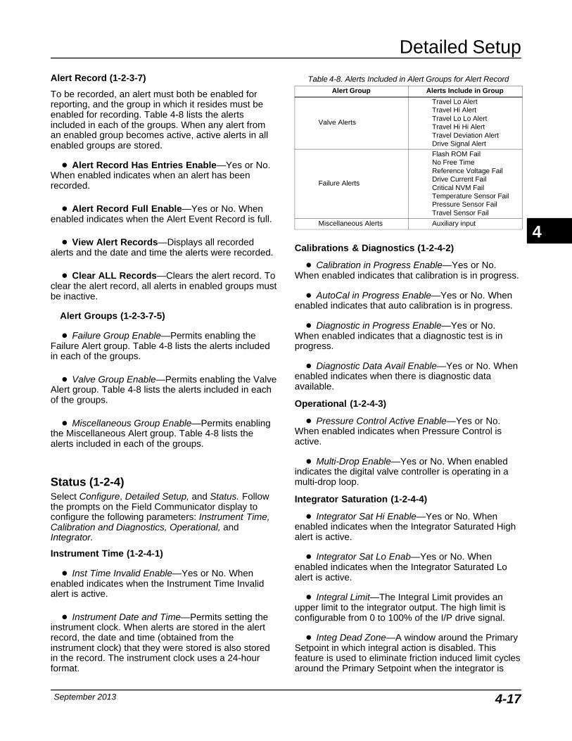
Detailed Setup
September 2013 4-17
Alert Record (1-2-3-7)
To be recorded, an alert must both be enabled forreporting, and the group in which it resides must beenabled for recording. Table 4-8 lists the alertsincluded in each of the groups. When any alert froman enabled group becomes active, active alerts in allenabled groups are stored.
� Alert Record Has Entries Enable—Yes or No.When enabled indicates when an alert has beenrecorded.
� Alert Record Full Enable—Yes or No. Whenenabled indicates when the Alert Event Record is full.
� View Alert Records—Displays all recordedalerts and the date and time the alerts were recorded.
� Clear ALL Records—Clears the alert record. Toclear the alert record, all alerts in enabled groups mustbe inactive.
Alert Groups (1-2-3-7-5)
� Failure Group Enable—Permits enabling theFailure Alert group. Table 4-8 lists the alerts includedin each of the groups.
� Valve Group Enable—Permits enabling the ValveAlert group. Table 4-8 lists the alerts included in eachof the groups.
� Miscellaneous Group Enable—Permits enablingthe Miscellaneous Alert group. Table 4-8 lists thealerts included in each of the groups.
Status (1-2-4)Select Configure, Detailed Setup, and Status. Followthe prompts on the Field Communicator display toconfigure the following parameters: Instrument Time,Calibration and Diagnostics, Operational, andIntegrator.
Instrument Time (1-2-4-1)
� Inst Time Invalid Enable—Yes or No. Whenenabled indicates when the Instrument Time Invalidalert is active.
� Instrument Date and Time—Permits setting theinstrument clock. When alerts are stored in the alertrecord, the date and time (obtained from theinstrument clock) that they were stored is also storedin the record. The instrument clock uses a 24-hourformat.
Table 4-8. Alerts Included in Alert Groups for Alert RecordAlert Group Alerts Include in Group
Valve Alerts
Travel Lo AlertTravel Hi AlertTravel Lo Lo AlertTravel Hi Hi AlertTravel Deviation AlertDrive Signal Alert
Failure Alerts
Flash ROM FailNo Free TimeReference Voltage FailDrive Current FailCritical NVM FailTemperature Sensor FailPressure Sensor FailTravel Sensor Fail
Miscellaneous Alerts Auxiliary input
Calibrations & Diagnostics (1-2-4-2)
� Calibration in Progress Enable—Yes or No.When enabled indicates that calibration is in progress.
� AutoCal in Progress Enable—Yes or No. Whenenabled indicates that auto calibration is in progress.
� Diagnostic in Progress Enable—Yes or No.When enabled indicates that a diagnostic test is inprogress.
� Diagnostic Data Avail Enable—Yes or No. Whenenabled indicates when there is diagnostic dataavailable.
Operational (1-2-4-3)
� Pressure Control Active Enable—Yes or No.When enabled indicates when Pressure Control isactive.
� Multi-Drop Enable—Yes or No. When enabledindicates the digital valve controller is operating in amulti-drop loop.
Integrator Saturation (1-2-4-4)
� Integrator Sat Hi Enable—Yes or No. Whenenabled indicates when the Integrator Saturated Highalert is active.
� Integrator Sat Lo Enab—Yes or No. Whenenabled indicates when the Integrator Saturated Loalert is active.
� Integral Limit—The Integral Limit provides anupper limit to the integrator output. The high limit isconfigurable from 0 to 100% of the I/P drive signal.
� Integ Dead Zone—A window around the PrimarySetpoint in which integral action is disabled. Thisfeature is used to eliminate friction induced limit cyclesaround the Primary Setpoint when the integrator is
4
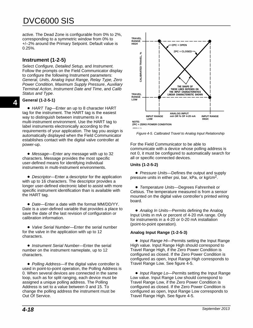
DVC6000 SIS
September 20134-18
active. The Dead Zone is configurable from 0% to 2%,corresponding to a symmetric window from 0% to+/−2% around the Primary Setpoint. Default value is0.25%.
Instrument (1-2-5)Select Configure, Detailed Setup, and Instrument.Follow the prompts on the Field Communicator displayto configure the following Instrument parameters:General, Units, Analog Input Range, Relay Type, ZeroPower Condition, Maximum Supply Pressure, AuxiliaryTerminal Action, Instrument Date and Time, and CalibStatus and Type.
General (1-2-5-1)
� HART Tag—Enter an up to 8 character HARTtag for the instrument. The HART tag is the easiestway to distinguish between instruments in amulti-instrument environment. Use the HART tag tolabel instruments electronically according to therequirements of your application. The tag you assign isautomatically displayed when the Field Communicatorestablishes contact with the digital valve controller atpower-up.
� Message—Enter any message with up to 32characters. Message provides the most specificuser-defined means for identifying individualinstruments in multi-instrument environments.
� Descriptor—Enter a descriptor for the applicationwith up to 16 characters. The descriptor provides alonger user-defined electronic label to assist with morespecific instrument identification than is available withthe HART tag.
� Date—Enter a date with the format MM/DD/YY.Date is a user-defined variable that provides a place tosave the date of the last revision of configuration orcalibration information.
� Valve Serial Number—Enter the serial numberfor the valve in the application with up to 12characters.
� Instrument Serial Number—Enter the serialnumber on the instrument nameplate, up to 12characters.
� Polling Address—If the digital valve controller isused in point-to-point operation, the Polling Address is0. When several devices are connected in the sameloop, such as for split ranging, each device must beassigned a unique polling address. The PollingAddress is set to a value between 0 and 15. Tochange the polling address the instrument must beOut Of Service.
TRAVELRANGEHIGH
TRAVELRANGELOW
THE SHAPE OFTHESE LINES DEPENDS ON
THE INPUT CHARACTERISTICSLINEAR CHARACTERISTIC SHOWN
INPUT RANGE LOW
INPUT RANGE HIGH
ANALOG INPUTmA OR % OF 4-20 mA
CA
LIB
RA
TE
D T
RA
VE
L, %
A6531-1 / IL
Figure 4-5. Calibrated Travel to Analog Input Relationship
ZPC = CLOSED
ZPC = OPEN
NOTE:ZPC = ZERO POWER CONDITION
For the Field Communicator to be able tocommunicate with a device whose polling address isnot 0, it must be configured to automatically search forall or specific connected devices.
Units (1-2-5-2)
� Pressure Units—Defines the output and supplypressure units in either psi, bar, kPa, or kg/cm2.
� Temperature Units—Degrees Fahrenheit orCelsius. The temperature measured is from a sensormounted on the digital valve controller’s printed wiringboard.
� Analog In Units—Permits defining the AnalogInput Units in mA or percent of 4-20 mA range. Onlyfor instruments in a 4-20 or 0-20 mA installation(point-to-point operation).
Analog Input Range (1-2-5-3)
� Input Range Hi—Permits setting the Input RangeHigh value. Input Range High should correspond toTravel Range High, if the Zero Power Condition isconfigured as closed. If the Zero Power Condition isconfigured as open, Input Range High corresponds toTravel Range Low. See figure 4-5.
� Input Range Lo—Permits setting the Input RangeLow value. Input Range Low should correspond toTravel Range Low, if the Zero Power Condition isconfigured as closed. If the Zero Power Condition isconfigured as open, Input Range Low corresponds toTravel Range High. See figure 4-5.
4
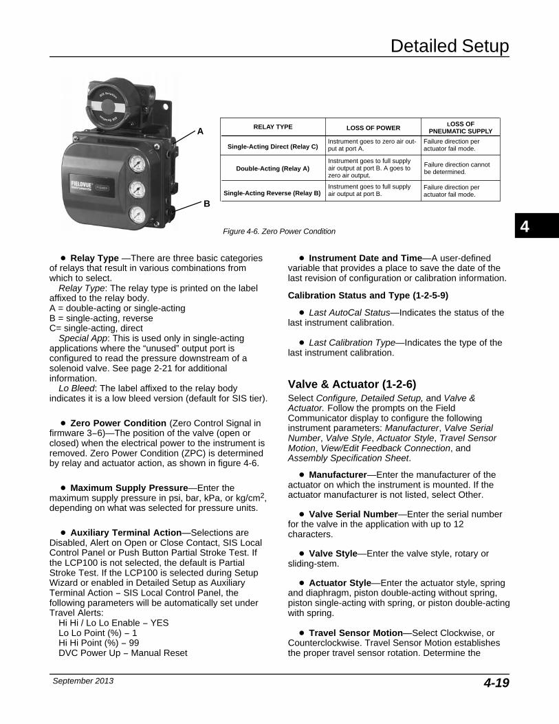
Detailed Setup
September 2013 4-19
A
B
Single-Acting Direct (Relay C)Instrument goes to zero air out-put at port A.
Failure direction per actuator fail mode.
Single-Acting Reverse (Relay B)Failure direction per actuator fail mode.
Double-Acting (Relay A)Failure direction cannotbe determined.
LOSS OF POWERLOSS OF
PNEUMATIC SUPPLY
Instrument goes to full supplyair output at port B.
Instrument goes to full supplyair output at port B. A goes tozero air output.
RELAY TYPE
Figure 4-6. Zero Power Condition
� Relay Type —There are three basic categoriesof relays that result in various combinations fromwhich to select.
Relay Type: The relay type is printed on the labelaffixed to the relay body. A = double-acting or single-actingB = single-acting, reverseC= single-acting, direct
Special App: This is used only in single-actingapplications where the “unused” output port isconfigured to read the pressure downstream of asolenoid valve. See page 2-21 for additionalinformation.
Lo Bleed: The label affixed to the relay bodyindicates it is a low bleed version (default for SIS tier).
� Zero Power Condition (Zero Control Signal infirmware 3−6)—The position of the valve (open orclosed) when the electrical power to the instrument isremoved. Zero Power Condition (ZPC) is determinedby relay and actuator action, as shown in figure 4-6.
� Maximum Supply Pressure—Enter themaximum supply pressure in psi, bar, kPa, or kg/cm2,depending on what was selected for pressure units.
� Auxiliary Terminal Action—Selections areDisabled, Alert on Open or Close Contact, SIS LocalControl Panel or Push Button Partial Stroke Test. Ifthe LCP100 is not selected, the default is PartialStroke Test. If the LCP100 is selected during SetupWizard or enabled in Detailed Setup as AuxiliaryTerminal Action − SIS Local Control Panel, thefollowing parameters will be automatically set underTravel Alerts:
Hi Hi / Lo Lo Enable − YESLo Lo Point (%) − 1Hi Hi Point (%) − 99DVC Power Up − Manual Reset
� Instrument Date and Time—A user-definedvariable that provides a place to save the date of thelast revision of configuration or calibration information.
Calibration Status and Type (1-2-5-9)
� Last AutoCal Status—Indicates the status of thelast instrument calibration.
� Last Calibration Type—Indicates the type of thelast instrument calibration.
Valve & Actuator (1-2-6)Select Configure, Detailed Setup, and Valve &Actuator. Follow the prompts on the FieldCommunicator display to configure the followinginstrument parameters: Manufacturer, Valve SerialNumber, Valve Style, Actuator Style, Travel SensorMotion, View/Edit Feedback Connection, andAssembly Specification Sheet.
� Manufacturer—Enter the manufacturer of theactuator on which the instrument is mounted. If theactuator manufacturer is not listed, select Other.
� Valve Serial Number—Enter the serial numberfor the valve in the application with up to 12characters.
� Valve Style—Enter the valve style, rotary orsliding-stem.
� Actuator Style—Enter the actuator style, springand diaphragm, piston double-acting without spring,piston single-acting with spring, or piston double-actingwith spring.
� Travel Sensor Motion—Select Clockwise, orCounterclockwise. Travel Sensor Motion establishesthe proper travel sensor rotation. Determine the
4
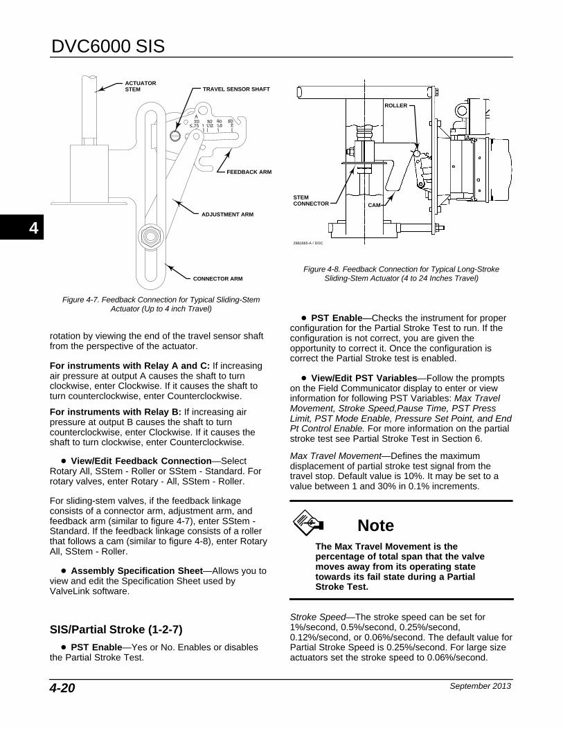
DVC6000 SIS
September 20134-20
Figure 4-7. Feedback Connection for Typical Sliding-StemActuator (Up to 4 inch Travel)
ACTUATORSTEM TRAVEL SENSOR SHAFT
FEEDBACK ARM
CONNECTOR ARM
ADJUSTMENT ARM
rotation by viewing the end of the travel sensor shaftfrom the perspective of the actuator.
For instruments with Relay A and C: If increasingair pressure at output A causes the shaft to turnclockwise, enter Clockwise. If it causes the shaft toturn counterclockwise, enter Counterclockwise.
For instruments with Relay B: If increasing airpressure at output B causes the shaft to turncounterclockwise, enter Clockwise. If it causes theshaft to turn clockwise, enter Counterclockwise.
� View/Edit Feedback Connection—SelectRotary All, SStem - Roller or SStem - Standard. Forrotary valves, enter Rotary - All, SStem - Roller.
For sliding-stem valves, if the feedback linkageconsists of a connector arm, adjustment arm, andfeedback arm (similar to figure 4-7), enter SStem -Standard. If the feedback linkage consists of a rollerthat follows a cam (similar to figure 4-8), enter RotaryAll, SStem - Roller.
� Assembly Specification Sheet—Allows you toview and edit the Specification Sheet used byValveLink software.
SIS/Partial Stroke (1-2-7)� PST Enable—Yes or No. Enables or disables
the Partial Stroke Test.
Figure 4-8. Feedback Connection for Typical Long-StrokeSliding-Stem Actuator (4 to 24 Inches Travel)
CAM
ROLLER
29B1665-A / DOC
STEM CONNECTOR
� PST Enable—Checks the instrument for properconfiguration for the Partial Stroke Test to run. If theconfiguration is not correct, you are given theopportunity to correct it. Once the configuration iscorrect the Partial Stroke test is enabled.
� View/Edit PST Variables—Follow the promptson the Field Communicator display to enter or viewinformation for following PST Variables: Max TravelMovement, Stroke Speed,Pause Time, PST PressLimit, PST Mode Enable, Pressure Set Point, and EndPt Control Enable. For more information on the partialstroke test see Partial Stroke Test in Section 6.
Max Travel Movement—Defines the maximumdisplacement of partial stroke test signal from thetravel stop. Default value is 10%. It may be set to avalue between 1 and 30% in 0.1% increments.
NoteThe Max Travel Movement is thepercentage of total span that the valvemoves away from its operating statetowards its fail state during a PartialStroke Test.
Stroke Speed—The stroke speed can be set for1%/second, 0.5%/second, 0.25%/second,0.12%/second, or 0.06%/second. The default value forPartial Stroke Speed is 0.25%/second. For large sizeactuators set the stroke speed to 0.06%/second.
4

Detailed Setup
September 2013 4-21
ACTUAL TRACE FROM TEST (TYPICAL)
ACTUAL TRACE FROM TEST (TYPICAL)
ACTUAL TRACE FROM TEST (TYPICAL)
Figure 4-9. Time Series Plots of Travel Set Point, Travel, Error, and Actuator Pressure for a Typical Emergency Shutdown Valve
Pause Time—Setup Wizard sets the Partial StrokePause Time to 5 seconds. This is the pause timebetween the up and down strokes of the test. It can beset for 5, 10, 15, 20 or 30 seconds.
PST Press Limit (single-acting actuators)—DuringSetup Wizard or Auto Travel Calibration, the PartialStroke Pressure Limit will be set to a positive value forsingle-acting actuators. For those actuators that ventfrom the test starting point, the pressure limit will be aminimum value. For those actuators that fill from thetest starting point, the pressure limit will be amaximum value. The pressure signal used for thisthreshold depends on relay type and is summarizedbelow.
Relay Type Pressure Signal
A or C Port A − Port BB Port B − Port AB Special App. Port BC Special App. Port A
PST Press Limit (double-acting actuators)— DuringSetup Wizard or Auto Travel Calibration, the PSTPress Limit will be set to a negative value for actuatorswhere the Partial Stroke Start Point is opposite of theZero Power Condition (e.g., Partial Stroke Start Point= Open and Zero Power Condition = Closed) and to apositive valve for actuators where the Partial StrokeStart Point is the same as the Zero Power Condition.
4
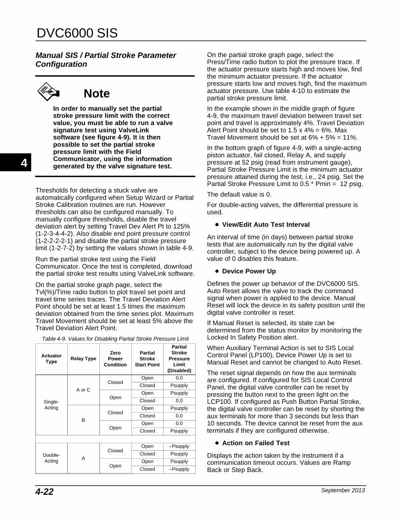
DVC6000 SIS
September 20134-22
Manual SIS / Partial Stroke ParameterConfiguration
NoteIn order to manually set the partialstroke pressure limit with the correctvalue, you must be able to run a valvesignature test using ValveLinksoftware (see figure 4-9). It is thenpossible to set the partial strokepressure limit with the FieldCommunicator, using the informationgenerated by the valve signature test.
Thresholds for detecting a stuck valve areautomatically configured when Setup Wizard or PartialStroke Calibration routines are run. Howeverthresholds can also be configured manually. Tomanually configure thresholds, disable the traveldeviation alert by setting Travel Dev Alert Pt to 125%(1-2-3-4-4-2). Also disable end point pressure control(1-2-2-2-2-1) and disable the partial stroke pressurelimit (1-2-7-2) by setting the values shown in table 4-9.
Run the partial stroke test using the FieldCommunicator. Once the test is completed, downloadthe partial stroke test results using ValveLink software.
On the partial stroke graph page, select theTvl(%)/Time radio button to plot travel set point andtravel time series traces. The Travel Deviation AlertPoint should be set at least 1.5 times the maximumdeviation obtained from the time series plot. MaximumTravel Movement should be set at least 5% above theTravel Deviation Alert Point.
Table 4-9. Values for Disabling Partial Stroke Pressure Limit
ActuatorType
Relay TypeZero
PowerCondition
PartialStroke
Start Point
PartialStroke
PressureLimit
(Disabled)
Single-Acting
A or C
ClosedOpen 0.0
Closed Psupply
OpenOpen Psupply
Closed 0.0
B
ClosedOpen Psupply
Closed 0.0
OpenOpen 0.0
Closed Psupply
Double-Acting A
ClosedOpen −Psupply
Closed Psupply
OpenOpen Psupply
Closed −Psupply
On the partial stroke graph page, select thePress/Time radio button to plot the pressure trace. Ifthe actuator pressure starts high and moves low, findthe minimum actuator pressure. If the actuatorpressure starts low and moves high, find the maximumactuator pressure. Use table 4-10 to estimate thepartial stroke pressure limit.
In the example shown in the middle graph of figure4-9, the maximum travel deviation between travel setpoint and travel is approximately 4%. Travel DeviationAlert Point should be set to 1.5 x 4% = 6%. MaxTravel Movement should be set at 6% + 5% = 11%.
In the bottom graph of figure 4-9, with a single-actingpiston actuator, fail closed, Relay A, and supplypressure at 52 psig (read from instrument gauge),Partial Stroke Pressure Limit is the minimum actuatorpressure attained during the test, i.e., 24 psig. Set thePartial Stroke Pressure Limit to 0.5 * Pmin = 12 psig.
The default value is 0.
For double-acting valves, the differential pressure isused.
� View/Edit Auto Test Interval
An interval of time (in days) between partial stroketests that are automatically run by the digital valvecontroller, subject to the device being powered up. Avalue of 0 disables this feature.
� Device Power Up
Defines the power up behavior of the DVC6000 SIS.Auto Reset allows the valve to track the commandsignal when power is applied to the device. ManualReset will lock the device in its safety position until thedigital valve controller is reset.
If Manual Reset is selected, its state can bedetermined from the status monitor by monitoring theLocked In Safety Position alert.
When Auxiliary Terminal Action is set to SIS LocalControl Panel (LP100), Device Power Up is set toManual Reset and cannot be changed to Auto Reset.
The reset signal depends on how the aux terminalsare configured. If configured for SIS Local ControlPanel, the digital valve controller can be reset bypressing the button next to the green light on theLCP100. If configured as Push Button Partial Stroke,the digital valve controller can be reset by shorting theaux terminals for more than 3 seconds but less than10 seconds. The device cannot be reset from the auxterminals if they are configured otherwise.
� Action on Failed Test
Displays the action taken by the instrument if acommunication timeout occurs. Values are RampBack or Step Back.
4
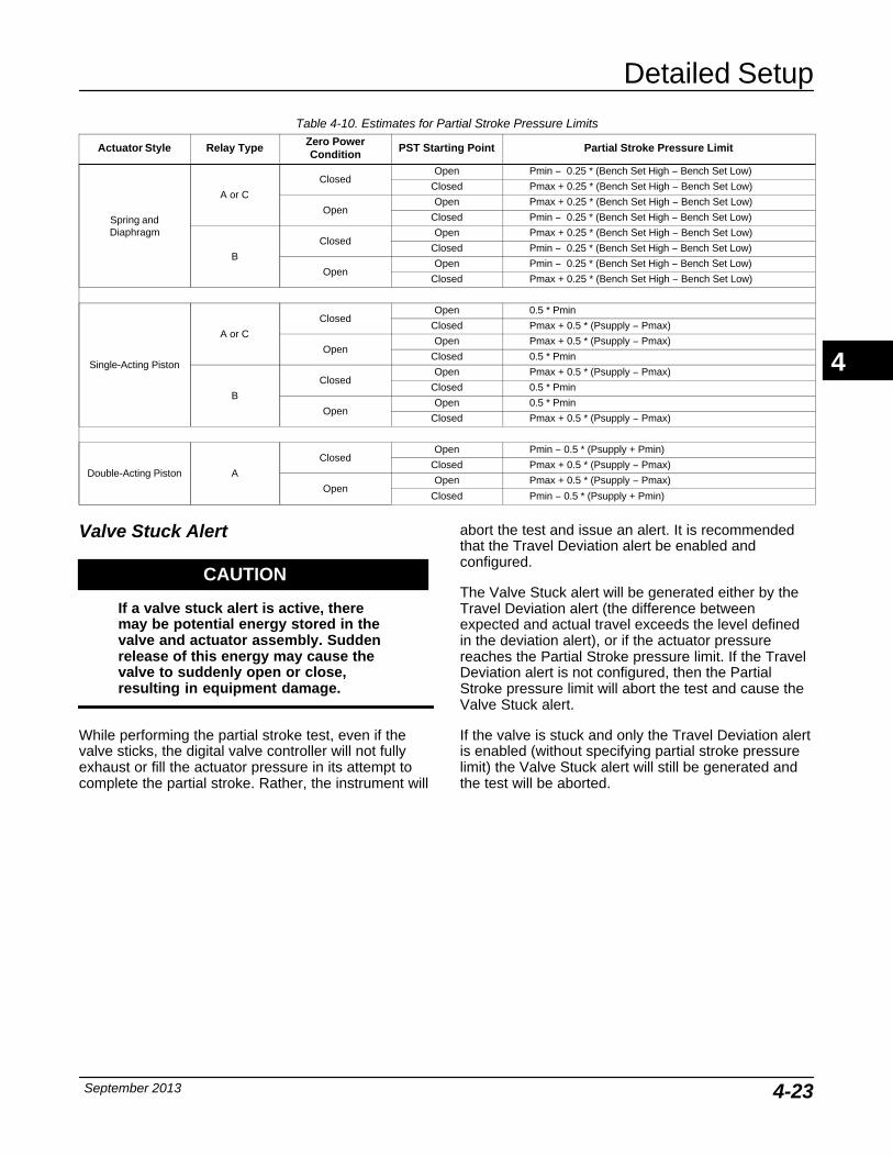
Detailed Setup
September 2013 4-23
Table 4-10. Estimates for Partial Stroke Pressure Limits
Actuator Style Relay Type Zero PowerCondition
PST Starting Point Partial Stroke Pressure Limit
Spring andDiaphragm
A or C
ClosedOpen Pmin − 0.25 * (Bench Set High − Bench Set Low)
Closed Pmax + 0.25 * (Bench Set High − Bench Set Low)
OpenOpen Pmax + 0.25 * (Bench Set High − Bench Set Low)
Closed Pmin − 0.25 * (Bench Set High − Bench Set Low)
B
ClosedOpen Pmax + 0.25 * (Bench Set High − Bench Set Low)
Closed Pmin − 0.25 * (Bench Set High − Bench Set Low)
OpenOpen Pmin − 0.25 * (Bench Set High − Bench Set Low)
Closed Pmax + 0.25 * (Bench Set High − Bench Set Low)
Single-Acting Piston
A or C
ClosedOpen 0.5 * Pmin
Closed Pmax + 0.5 * (Psupply − Pmax)
OpenOpen Pmax + 0.5 * (Psupply − Pmax)
Closed 0.5 * Pmin
B
ClosedOpen Pmax + 0.5 * (Psupply − Pmax)
Closed 0.5 * Pmin
OpenOpen 0.5 * Pmin
Closed Pmax + 0.5 * (Psupply − Pmax)
Double-Acting Piston A
ClosedOpen Pmin − 0.5 * (Psupply + Pmin)
Closed Pmax + 0.5 * (Psupply − Pmax)
OpenOpen Pmax + 0.5 * (Psupply − Pmax)
Closed Pmin − 0.5 * (Psupply + Pmin)
Valve Stuck Alert
CAUTION
If a valve stuck alert is active, theremay be potential energy stored in thevalve and actuator assembly. Suddenrelease of this energy may cause thevalve to suddenly open or close,resulting in equipment damage.
While performing the partial stroke test, even if thevalve sticks, the digital valve controller will not fullyexhaust or fill the actuator pressure in its attempt tocomplete the partial stroke. Rather, the instrument will
abort the test and issue an alert. It is recommendedthat the Travel Deviation alert be enabled andconfigured.
The Valve Stuck alert will be generated either by theTravel Deviation alert (the difference betweenexpected and actual travel exceeds the level definedin the deviation alert), or if the actuator pressurereaches the Partial Stroke pressure limit. If the TravelDeviation alert is not configured, then the PartialStroke pressure limit will abort the test and cause theValve Stuck alert.
If the valve is stuck and only the Travel Deviation alertis enabled (without specifying partial stroke pressurelimit) the Valve Stuck alert will still be generated andthe test will be aborted.
4
DVC6000 SIS
September 20134-24
4
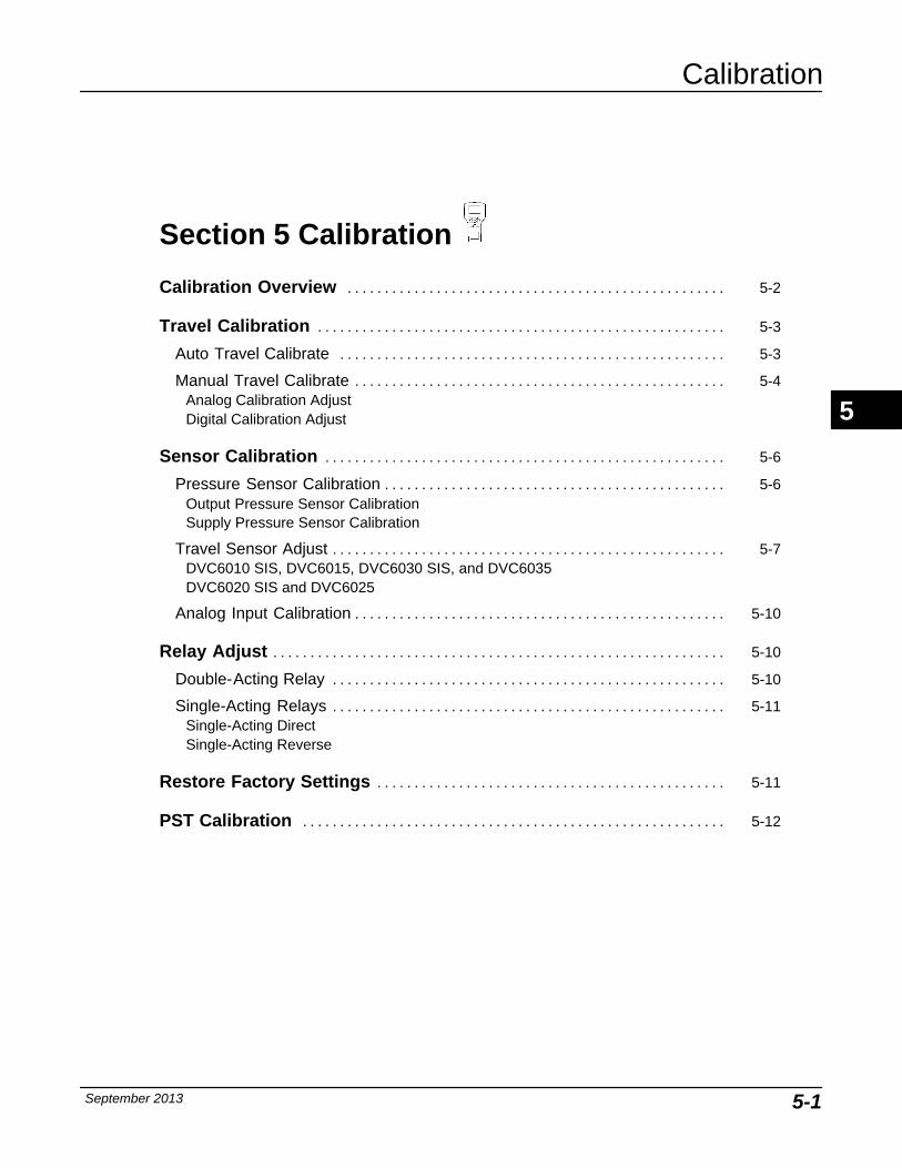
Calibration
September 2013 5-1
5-5
Section 5 Calibration
Calibration Overview 5-2. . . . . . . . . . . . . . . . . . . . . . . . . . . . . . . . . . . . . . . . . . . . . . . . . . .
Travel Calibration 5-3. . . . . . . . . . . . . . . . . . . . . . . . . . . . . . . . . . . . . . . . . . . . . . . . . . . . . . .
Auto Travel Calibrate 5-3. . . . . . . . . . . . . . . . . . . . . . . . . . . . . . . . . . . . . . . . . . . . . . . . . . . .
Manual Travel Calibrate 5-4. . . . . . . . . . . . . . . . . . . . . . . . . . . . . . . . . . . . . . . . . . . . . . . . . .Analog Calibration AdjustDigital Calibration Adjust
Sensor Calibration 5-6. . . . . . . . . . . . . . . . . . . . . . . . . . . . . . . . . . . . . . . . . . . . . . . . . . . . . .
Pressure Sensor Calibration 5-6. . . . . . . . . . . . . . . . . . . . . . . . . . . . . . . . . . . . . . . . . . . . . .Output Pressure Sensor CalibrationSupply Pressure Sensor Calibration
Travel Sensor Adjust 5-7. . . . . . . . . . . . . . . . . . . . . . . . . . . . . . . . . . . . . . . . . . . . . . . . . . . . .DVC6010 SIS, DVC6015, DVC6030 SIS, and DVC6035DVC6020 SIS and DVC6025
Analog Input Calibration 5-10. . . . . . . . . . . . . . . . . . . . . . . . . . . . . . . . . . . . . . . . . . . . . . . . . .
Relay Adjust 5-10. . . . . . . . . . . . . . . . . . . . . . . . . . . . . . . . . . . . . . . . . . . . . . . . . . . . . . . . . . . . .
Double-Acting Relay 5-10. . . . . . . . . . . . . . . . . . . . . . . . . . . . . . . . . . . . . . . . . . . . . . . . . . . . .
Single-Acting Relays 5-11. . . . . . . . . . . . . . . . . . . . . . . . . . . . . . . . . . . . . . . . . . . . . . . . . . . . .Single-Acting DirectSingle-Acting Reverse
Restore Factory Settings 5-11. . . . . . . . . . . . . . . . . . . . . . . . . . . . . . . . . . . . . . . . . . . . . . .
PST Calibration 5-12. . . . . . . . . . . . . . . . . . . . . . . . . . . . . . . . . . . . . . . . . . . . . . . . . . . . . . . . .
5
DVC6000 SIS
September 20135-2
Calibration Overview When a DVC6000 SIS digital valve controller isordered as part of a control valve assembly, thefactory mounts the digital valve controller on theactuator and connects the necessary tubing, then setsup and calibrates the controller.
For digital valve controllers that are orderedseparately, recalibration of the analog input orpressure sensors generally is unnecessary. However,after mounting on an actuator, perform the initial setup(either auto or manual), then calibrate travel byselecting Calibrate, Travel Calibration, and AutoCalibration from the Configure menu. For moredetailed calibration information, refer to the followingcalibration procedures, available from the Calibratemenu:
Travel Calibration
� Auto Calibration —This procedure automaticallycalibrates the travel. The calibration procedure usesthe valve and actuator stops as the 0% and 100%calibration points.
� Manual Calibration —This procedure permitsmanual calibration of the travel. This calibrationprocedure allows you to determine the 0% and 100%calibration points and obtain the optimum linearity on asliding-stem valve.
Sensor Calibration
� Pressure Sensors—This procedure permitscalibrating the three pressure sensors. Normally thesensors are calibrated at the factory and should notneed calibration.
� Travel Sensor—This procedure permitscalibrating the travel sensor. Normally the travelsensor is calibrated at the factory. Calibrating thetravel sensor should only be necessary if the travelsensor is replaced.
� Analog Input—This procedure permitscalibrating the analog input sensor. Normally thesensor is calibrated at the factory and should not needcalibration.
NoteAnalog Input is only available whenthe DVC6000 SIS is operating inPoint-to-Point mode with 4-20 mA or0-20 mA current.
Relay Adjust—This procedure permits adjustment ofthe pneumatic relay.
Restore Factory Settings—This procedure permitsyou to restore the calibration settings back to thefactory settings.
PST Calibration—This procedure permits you to runthe PST calibration procedure.
To display the calibrate menu, from the Online menu,select Configure and Calibrate.
NoteThe Instrument Mode must be Out OfService and the Protection set to Nonebefore the instrument can be calibrated.
If you are operating in burst mode, werecommend that you disable burst beforecontinuing calibration. Once calibration iscomplete, burst mode may then be turnedback on.
NoteIn the event of a power failure theDVC6000 SIS automatically restoresthe device to In Service uponrestoration of power. This is to providegreater availability of the safetyfunction.
If power is inadvertently interruptedwhile performing set up ormaintenance, you may need to returnthe DVC6000 SIS to out of service ifthe interrupted task requires that modeof operation.
WARNING
During calibration, the valve maymove. To avoid personal injury andproperty damage caused by therelease of process fluid or pressure,isolate the valve from the process andequalize pressure on both sides of thevalve or bleed off the process fluid.
5
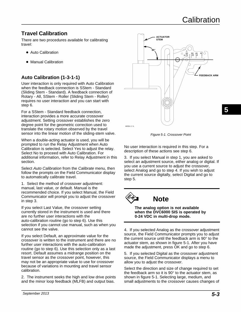
Calibration
September 2013 5-3
Travel Calibration There are two procedures available for calibratingtravel:
� Auto Calibration
� Manual Calibration
Auto Calibration (1-3-1-1) User interaction is only required with Auto Calibrationwhen the feedback connection is SStem - Standard(Sliding Stem - Standard). A feedback connection ofRotary - All, SStem - Roller (Sliding Stem - Roller)requires no user interaction and you can start withstep 6.
For a SStem - Standard feedback connection,interaction provides a more accurate crossoveradjustment. Setting crossover establishes the zerodegree point for the geometric correction used totranslate the rotary motion observed by the travelsensor into the linear motion of the sliding-stem valve.
When a double-acting actuator is used, you will beprompted to run the Relay Adjustment when AutoCalibration is selected. Select Yes to adjust the relay.Select No to proceed with Auto Calibration. Foradditional information, refer to Relay Adjustment in thissection.
Select Auto Calibration from the Calibrate menu, thenfollow the prompts on the Field Communicator displayto automatically calibrate travel.
1. Select the method of crossover adjustment:manual, last value, or default. Manual is therecommended choice. If you select Manual, the FieldCommunicator will prompt you to adjust the crossoverin step 3.
If you select Last Value, the crossover settingcurrently stored in the instrument is used and thereare no further user interactions with theauto-calibration routine (go to step 6). Use thisselection if you cannot use manual, such as when youcannot see the valve.
If you select Default, an approximate value for thecrossover is written to the instrument and there are nofurther user interactions with the auto-calibrationroutine (go to step 6). Use this selection only as a lastresort. Default assumes a midrange position on thetravel sensor as the crossover point, however, thismay not be an appropriate value to use for crossoverbecause of variations in mounting and travel sensorcalibration.
2. The instrument seeks the high and low drive pointsand the minor loop feedback (MLFB) and output bias.
Figure 5-1. Crossover Point
ACTUATORSTEM
FEEDBACK ARM
90�
A6536−3 / IL
No user interaction is required in this step. For adescription of these actions see step 6.
3. If you select Manual in step 1, you are asked toselect an adjustment source, either analog or digital. Ifyou use a current source to adjust the crossover,select Analog and go to step 4. If you wish to adjustthe current source digitally, select Digital and go tostep 5.
NoteThe analog option is not availablewhen the DVC6000 SIS is operated by0-24 VDC in multi-drop mode.
4. If you selected Analog as the crossover adjustmentsource, the Field Communicator prompts you to adjustthe current source until the feedback arm is 90° to theactuator stem, as shown in figure 5-1. After you havemade the adjustment, press OK and go to step 6.
5. If you selected Digital as the crossover adjustmentsource, the Field Communicator displays a menu toallow you to adjust the crossover.
Select the direction and size of change required to setthe feedback arm so it is 90° to the actuator stem, asshown in figure 5-1. Selecting large, medium, andsmall adjustments to the crossover causes changes of
5
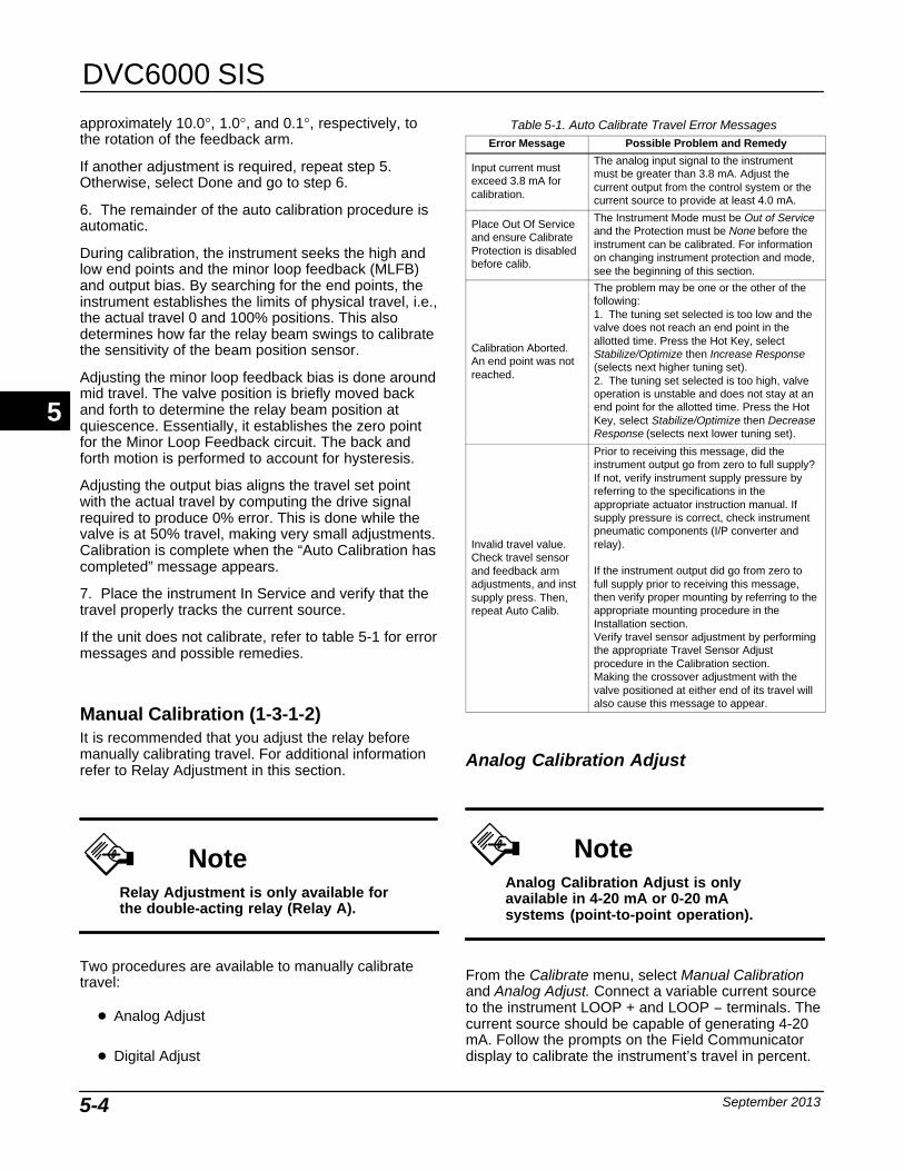
DVC6000 SIS
September 20135-4
approximately 10.0°, 1.0°, and 0.1°, respectively, tothe rotation of the feedback arm.
If another adjustment is required, repeat step 5.Otherwise, select Done and go to step 6.
6. The remainder of the auto calibration procedure isautomatic.
During calibration, the instrument seeks the high andlow end points and the minor loop feedback (MLFB)and output bias. By searching for the end points, theinstrument establishes the limits of physical travel, i.e.,the actual travel 0 and 100% positions. This alsodetermines how far the relay beam swings to calibratethe sensitivity of the beam position sensor.
Adjusting the minor loop feedback bias is done aroundmid travel. The valve position is briefly moved backand forth to determine the relay beam position atquiescence. Essentially, it establishes the zero pointfor the Minor Loop Feedback circuit. The back andforth motion is performed to account for hysteresis.
Adjusting the output bias aligns the travel set pointwith the actual travel by computing the drive signalrequired to produce 0% error. This is done while thevalve is at 50% travel, making very small adjustments.Calibration is complete when the “Auto Calibration hascompleted” message appears.
7. Place the instrument In Service and verify that thetravel properly tracks the current source.
If the unit does not calibrate, refer to table 5-1 for errormessages and possible remedies.
Manual Calibration (1-3-1-2) It is recommended that you adjust the relay beforemanually calibrating travel. For additional informationrefer to Relay Adjustment in this section.
NoteRelay Adjustment is only available forthe double-acting relay (Relay A).
Two procedures are available to manually calibratetravel:
� Analog Adjust
� Digital Adjust
Table 5-1. Auto Calibrate Travel Error Messages Error Message Possible Problem and Remedy
Input current mustexceed 3.8 mA forcalibration.
The analog input signal to the instrumentmust be greater than 3.8 mA. Adjust thecurrent output from the control system or thecurrent source to provide at least 4.0 mA.
Place Out Of Serviceand ensure CalibrateProtection is disabledbefore calib.
The Instrument Mode must be Out of Serviceand the Protection must be None before theinstrument can be calibrated. For informationon changing instrument protection and mode,see the beginning of this section.
Calibration Aborted.An end point was notreached.
The problem may be one or the other of thefollowing:1. The tuning set selected is too low and thevalve does not reach an end point in theallotted time. Press the Hot Key, selectStabilize/Optimize then Increase Response(selects next higher tuning set).2. The tuning set selected is too high, valveoperation is unstable and does not stay at anend point for the allotted time. Press the HotKey, select Stabilize/Optimize then DecreaseResponse (selects next lower tuning set).
Invalid travel value.Check travel sensorand feedback armadjustments, and instsupply press. Then,repeat Auto Calib.
Prior to receiving this message, did theinstrument output go from zero to full supply?If not, verify instrument supply pressure byreferring to the specifications in theappropriate actuator instruction manual. Ifsupply pressure is correct, check instrumentpneumatic components (I/P converter andrelay).
If the instrument output did go from zero tofull supply prior to receiving this message,then verify proper mounting by referring to theappropriate mounting procedure in theInstallation section.Verify travel sensor adjustment by performingthe appropriate Travel Sensor Adjustprocedure in the Calibration section.Making the crossover adjustment with thevalve positioned at either end of its travel willalso cause this message to appear.
Analog Calibration Adjust
NoteAnalog Calibration Adjust is onlyavailable in 4-20 mA or 0-20 mAsystems (point-to-point operation).
From the Calibrate menu, select Manual Calibrationand Analog Adjust. Connect a variable current sourceto the instrument LOOP + and LOOP − terminals. Thecurrent source should be capable of generating 4-20mA. Follow the prompts on the Field Communicatordisplay to calibrate the instrument’s travel in percent.
5
Calibration
September 2013 5-5
Note0% Travel = Valve Closed100% Travel = Valve Open
1. Adjust the input current until the valve is nearmid-travel. Press OK.
2. If the feedback connection is Rotary - All, SStem -Roller, go to step 6. If the feedback connection isSStem - Standard, you are prompted to set thecrossover point. Adjust the current source until thefeedback arm is 90° to the actuator stem, as shown infigure 5-1. Then press OK.
NoteIn steps 3 through 7, the accuracy ofthe current source adjustment affectsthe position accuracy.
3. Adjust the current source until the valve is at 0%travel, then press OK.
4. Adjust the current source until the valve is at 100%travel, then press OK.
5. Adjust the current source until the valve is at 50%travel, then press OK.
6. Adjust the current source until the valve is at 0%travel, then press OK.
7. Adjust the current source until the valve is at 100%travel, then press OK.
8. Adjust the current source until the valve is near 5%travel, then press OK.
9. Adjust the current source until the valve is near95% travel, then press OK.
10. Place the instrument In Service and verify that thetravel properly tracks the current source.
Digital Calibration AdjustFrom the Calibrate menu, select Manual Calibrationand Digital Adjust. Connect a variable current sourceto the instrument LOOP + and LOOP − terminals. Thecurrent source should be set between 4 and 20 mA.Follow the prompts on the Field Communicator displayto calibrate the instrument’s travel in percent.
Note0% Travel = Valve Closed100% Travel = Valve Open
1. Adjust the input current until the valve is nearmid-travel. Press OK.
2. From the adjustment menu, select the direction andsize of change required to adjust the output until thevalve is near mid-travel. Selecting large, medium, andsmall adjustments causes changes of approximately10.0°, 1.0°, and 0.1°, respectively, to the feedbackarm rotation.
If another adjustment is required, repeat step 2.Otherwise, select Done and go to step 3.
3. If the feedback connection is Rotary - All, SStem -Roller, go to step 8. If the feedback connection isSStem - Standard, adjust the feedback arm to thecrossover point by using the adjustment menu.
4. From the adjustment menu, select the direction andsize of change required to set the feedback arm so itis 90° to the actuator stem, as shown in figure 5-1.Selecting large, medium, and small adjustments to thecrossover causes changes of approximately 10.0°,1.0°, and 0.1°, respectively, to the feedback armrotation.
If another adjustment is required, repeat step 4.Otherwise, select Done and go to step 5.
5. From the adjustment menu, select the direction andsize of change required to set the travel at 0%.Selecting large, medium, and small adjustmentscauses changes of approximately 10.0°, 1.0°, and0.1°, respectively, to the feedback arm rotation.
If another adjustment is required, repeat step 5.Otherwise, select Done and go to step 6.
6. From the adjustment menu, select the direction andsize of change required to set the travel to 100%.Selecting large, medium, and small adjustmentscauses changes of approximately 10.0°, 1.0°, and0.1°, respectively, to the feedback arm rotation.
If another adjustment is required, repeat step 6.Otherwise, select Done and go to step 7.
7. From the adjustment menu, select the direction andsize of change required to set the travel to 50%.Selecting large, medium, and small adjustmentscauses changes of approximately 10.0°, 1.0°, and0.1°, respectively, to the feedback arm rotation.
If another adjustment is required, repeat step 7.Otherwise, select Done and go to step 8.
5
DVC6000 SIS
September 20135-6
8. From the adjustment menu, select the direction andsize of change required to set the travel to 0%.Selecting large, medium, and small adjustmentscauses changes of approximately 10.0°, 1.0°, and0.1°, respectively, to the feedback arm rotation for asliding-stem valve or to the travel for a rotary valve.
If another adjustment is required, repeat step 8.Otherwise, select Done and go to step 9.
9. From the adjustment menu, select the direction andsize of change required to set the travel to 100%.Selecting large, medium, and small adjustmentscauses changes of approximately 10.0°, 1.0°, and0.1°, respectively, to the feedback arm rotation for asliding-stem valve or to the travel for a rotary valve.
If another adjustment is required, repeat step 9.Otherwise, select Done and go to step 10.
10. From the adjustment menu, select the directionand size of change required to set the travel to near5%. Selecting large, medium, and small adjustmentscauses changes of approximately 10.0°, 1.0°, and0.1°, respectively, to the feedback arm rotation for asliding-stem valve or to the travel for a rotary valve.
If another adjustment is required, repeat step 10.Otherwise, select Done and go to step 11.
11. From the adjustment menu, select the directionand size of change required to set the travel to near95%. Selecting large, medium, and small adjustmentscauses changes of approximately 10.0°, 1.0°, and0.1°, respectively, to the feedback arm rotation for asliding-stem valve or to the travel for a rotary valve.
If another adjustment is required, repeat step 11.Otherwise, select Done and go to step 12.
12. Place the instrument In Service and verify that thetravel properly tracks the current source.
13. After manual calibration is completed manually setthe SIS parameters as described in Section 4. Seepage 4-11 for End Point Pressure Control; page 4-14Travel Deviation Alert Point and Travel DeviationTime; and page 4-21 for Partial Stroke Pressure Limit.
Sensor Calibration
Pressure Sensors (1-3-2-1) There are three pressure sensors: output A, output Band supply. Select the appropriate menu dependingupon which pressure sensor you are calibrating.
NoteThe pressure sensors are calibrated atthe factory and should not requirecalibration.
Output Pressure Sensor CalibrationTo calibrate the output pressure sensors, connect anexternal reference gauge to the output beingcalibrated. The gauge should be capable of measuringmaximum instrument supply pressure. From theCalibrate menu, select Sensor Calibration andPressure Sensors. Depending upon the sensor youwish to calibrate, select either Output A Sensor orOutput B Sensor. Follow the prompts on the FieldCommunicator display to calibrate the instrument’soutput pressure sensor.
1. Adjust the supply pressure regulator to the desiredsupply pressure. Press OK.
2. Select a) Zero only, or b) Zero and Span (gaugerequired) sensor calibration.
a. If Zero only calibration is selected, wait untiloutput x pressure has completely exhausted, thencontinue. Once calibration is completed, go to step6. The output x pressure corresponds to A or B,depending on which output you are calibrating.
b. If Zero and Span calibration is selected, waituntil output x pressure has completely exhausted,then continue. You will then be asked to wait untiloutput x pressure has reached full supply, thencontinue. The output x pressure corresponds to Aor B, depending on which output you arecalibrating. Proceed with step 3.
3. The instrument sets the output pressure to fullsupply. The following message appears:
Use the Increase andDecrease selectionsuntil the displayedpressure matches theoutput x pressure.
The output x pressure corresponds to A or B,depending on which output you are calibrating. PressOK when you have read the message.
4. The value of the output pressure appears on thedisplay.
5. From the adjustment menu, select the direction andsize of adjustment to the displayed value. Selecting
5
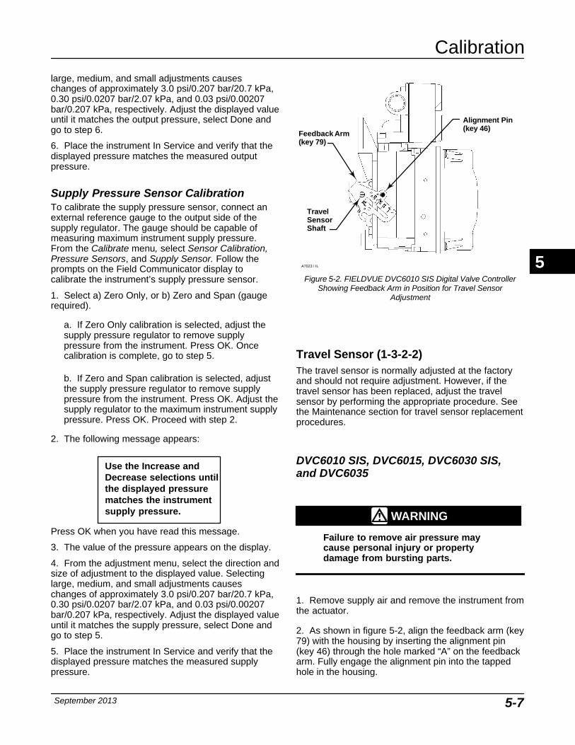
Calibration
September 2013 5-7
large, medium, and small adjustments causeschanges of approximately 3.0 psi/0.207 bar/20.7 kPa,0.30 psi/0.0207 bar/2.07 kPa, and 0.03 psi/0.00207bar/0.207 kPa, respectively. Adjust the displayed valueuntil it matches the output pressure, select Done andgo to step 6.
6. Place the instrument In Service and verify that thedisplayed pressure matches the measured outputpressure.
Supply Pressure Sensor CalibrationTo calibrate the supply pressure sensor, connect anexternal reference gauge to the output side of thesupply regulator. The gauge should be capable ofmeasuring maximum instrument supply pressure.From the Calibrate menu, select Sensor Calibration,Pressure Sensors, and Supply Sensor. Follow theprompts on the Field Communicator display tocalibrate the instrument’s supply pressure sensor.
1. Select a) Zero Only, or b) Zero and Span (gaugerequired).
a. If Zero Only calibration is selected, adjust thesupply pressure regulator to remove supplypressure from the instrument. Press OK. Oncecalibration is complete, go to step 5.
b. If Zero and Span calibration is selected, adjustthe supply pressure regulator to remove supplypressure from the instrument. Press OK. Adjust thesupply regulator to the maximum instrument supplypressure. Press OK. Proceed with step 2.
2. The following message appears:
Use the Increase andDecrease selections untilthe displayed pressurematches the instrumentsupply pressure.
Press OK when you have read this message.
3. The value of the pressure appears on the display.
4. From the adjustment menu, select the direction andsize of adjustment to the displayed value. Selectinglarge, medium, and small adjustments causeschanges of approximately 3.0 psi/0.207 bar/20.7 kPa,0.30 psi/0.0207 bar/2.07 kPa, and 0.03 psi/0.00207bar/0.207 kPa, respectively. Adjust the displayed valueuntil it matches the supply pressure, select Done andgo to step 5.
5. Place the instrument In Service and verify that thedisplayed pressure matches the measured supplypressure.
Figure 5-2. FIELDVUE DVC6010 SIS Digital Valve ControllerShowing Feedback Arm in Position for Travel Sensor
Adjustment
Feedback Arm(key 79)
A
BTravel SensorShaft
Alignment Pin(key 46)
A7023 / IL
Travel Sensor (1-3-2-2) The travel sensor is normally adjusted at the factoryand should not require adjustment. However, if thetravel sensor has been replaced, adjust the travelsensor by performing the appropriate procedure. Seethe Maintenance section for travel sensor replacementprocedures.
DVC6010 SIS, DVC6015, DVC6030 SIS,and DVC6035
WARNING
Failure to remove air pressure maycause personal injury or propertydamage from bursting parts.
1. Remove supply air and remove the instrument fromthe actuator.
2. As shown in figure 5-2, align the feedback arm (key79) with the housing by inserting the alignment pin(key 46) through the hole marked “A” on the feedbackarm. Fully engage the alignment pin into the tappedhole in the housing.
5
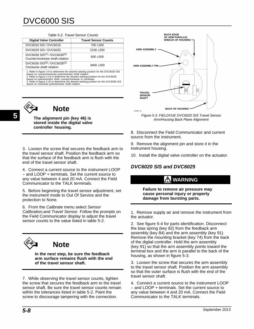
DVC6000 SIS
September 20135-8
Table 5-2. Travel Sensor CountsDigital Valve Controller Travel Sensor Counts
DVC6010 SIS / DVC6015 700 ±200
DVC6020 SIS / DVC6025 2100 ±200
DVC6030 SIS(1) / DVC6035(2)
Counterclockwise shaft rotation600 ±200
DVC6030 SIS(3) / DVC6035(2)
Clockwise shaft rotation3400 ±200
1. Refer to figure 2-9 to determine the desired starting position for the DVC6030 SISbased on counterclockwise potentiometer shaft rotation.2. Refer to figure 2-14 to determine the desired starting position for the DVC6035based on potentiometer shaft; counterclockwise or clockwise. 3. Refer to figure 2-10 to determine the desired starting position for the DVC6030 SISbased on clockwise potentiometer shaft rotation.
NoteThe alignment pin (key 46) isstored inside the digital valvecontroller housing.
3. Loosen the screw that secures the feedback arm tothe travel sensor shaft. Position the feedback arm sothat the surface of the feedback arm is flush with theend of the travel sensor shaft.
4. Connect a current source to the instrument LOOP− and LOOP + terminals. Set the current source toany value between 4 and 20 mA. Connect the FieldCommunicator to the TALK terminals.
5. Before beginning the travel sensor adjustment, setthe instrument mode to Out Of Service and theprotection to None.
6. From the Calibrate menu select SensorCalibration,and Travel Sensor. Follow the prompts onthe Field Communicator display to adjust the travelsensor counts to the value listed in table 5-2.
NoteIn the next step, be sure the feedbackarm surface remains flush with the endof the travel sensor shaft.
7. While observing the travel sensor counts, tightenthe screw that secures the feedback arm to the travelsensor shaft. Be sure the travel sensor counts remainwithin the tolerances listed in table 5-2. Paint thescrew to discourage tampering with the connection.
TRAVELSENSORSHAFT
Figure 5-3. FIELDVUE DVC6020 SIS Travel SensorArm/Housing Back Plane Alignment
ARM ASSEMBLY
BACK OF HOUSING
ARM ASSEMBLY PIN
BACK EDGEOF ARM PARALLELW/BACK OF HOUSING
A7025 / IL
8. Disconnect the Field Communicator and currentsource from the instrument.
9. Remove the alignment pin and store it in theinstrument housing.
10. Install the digital valve controller on the actuator.
DVC6020 SIS and DVC6025
WARNING
Failure to remove air pressure maycause personal injury or propertydamage from bursting parts.
1. Remove supply air and remove the instrument fromthe actuator.
2. See figure 5-4 for parts identification. Disconnectthe bias spring (key 82) from the feedback armassembly (key 84) and the arm assembly (key 91).Remove the mounting bracket (key 74) from the backof the digital controller. Hold the arm assembly (key 91) so that the arm assembly points toward theterminal box and the arm is parallel to the back of thehousing, as shown in figure 5-3.
3. Loosen the screw that secures the arm assemblyto the travel sensor shaft. Position the arm assemblyso that the outer surface is flush with the end of thetravel sensor shaft.
4. Connect a current source to the instrument LOOP− and LOOP + terminals. Set the current source toany value between 4 and 20 mA. Connect the FieldCommunicator to the TALK terminals.
5
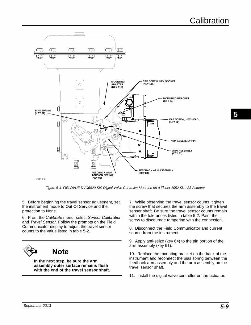
Calibration
September 2013 5-9
Figure 5-4. FIELDVUE DVC6020 SIS Digital Valve Controller Mounted on a Fisher 1052 Size 33 Actuator
MOUNTINGADAPTER(KEY 117)
FEEDBACK ARM ASSEMBLY(KEY 84)FEEDBACK ARM
TORSION SPRING(KEY 93)
BIAS SPRING(KEY 82)
ARM ASSEMBLY PIN
ARM ASSEMBLY(KEY 91)
MOUNTING BRACKET(KEY 74)
CAP SCREW, HEX SOCKET(KEY 116)
CAP SCREW, HEX HEAD(KEY 92)
A7024 -2/ IL
5. Before beginning the travel sensor adjustment, setthe instrument mode to Out Of Service and theprotection to None.
6. From the Calibrate menu, select Sensor Calibrationand Travel Sensor. Follow the prompts on the FieldCommunicator display to adjust the travel sensorcounts to the value listed in table 5-2.
NoteIn the next step, be sure the armassembly outer surface remains flushwith the end of the travel sensor shaft.
7. While observing the travel sensor counts, tightenthe screw that secures the arm assembly to the travelsensor shaft. Be sure the travel sensor counts remainwithin the tolerances listed in table 5-2. Paint thescrew to discourage tampering with the connection.
8. Disconnect the Field Communicator and currentsource from the instrument.
9. Apply anti-seize (key 64) to the pin portion of thearm assembly (key 91).
10. Replace the mounting bracket on the back of theinstrument and reconnect the bias spring between thefeedback arm assembly and the arm assembly on thetravel sensor shaft.
11. Install the digital valve controller on the actuator.
5
DVC6000 SIS
September 20135-10
Analog Input (1-3-2-3)
NoteAnalog Input Calibration is onlyavailable in 4-wire systems(point-to-point operation).
To calibrate the analog input sensor, connect avariable current source to the instrument LOOP+ andLOOP− terminals. The current source should becapable of generating an output of 4 to 20 mA. Fromthe Configure menu select Calibrate, SensorCalibration, and Analog In. Follow the prompts on theField Communicator display to calibrate the analoginput sensor.
1. Set the current source to the target value shown onthe display. The target value is the Input Range Lowvalue. Press OK.
2. The following message appears:
Use Increase andDecrease selectionsuntil the displayedcurrent matches thecurrent source.
Press OK when you have read this message.
3. The value of the Analog Input appears on thedisplay.
4. From the adjustment menu, select the direction andsize of adjustment to the displayed value. Selectinglarge, medium, and small adjustments causeschanges of approximately 0.4 mA, 0.04 mA, and 0.004mA, respectively. Adjust the displayed value until itmatches the current source, select Done and go tostep 5.
5. Set the current source to the target value shown onthe display. The target value is the Input Range Highvalue. Press OK.
6. The following message appears:
Use Increase andDecrease selectionsuntil the displayedcurrent matches thecurrent source.
Press OK when you have read this message.
7. The value of the Analog Input appears on thedisplay.
8. From the adjustment menu, select the direction andsize of adjustment to the displayed value. Selectinglarge, medium, and small adjustments causeschanges of approximately 0.4 mA, 0.04 mA, and 0.004mA, respectively. Adjust the displayed value until itmatches the current source, select Done and go tostep 9.
9. Place the instrument In Service and verify that theanalog input displayed matches the current source.
Relay Adjust (1-3-3) Before beginning travel calibration, check the relayadjustment. To check relay adjustment, select Relayfrom the Calibrate menu, then follow the prompts onthe Field Communicator display. Replace the digitalvalve controller cover when finished.
NoteRelay B and C are not user-adjustable.
Double-Acting RelayThe double-acting relay is designated by “Relay A” ona label affixed to the relay itself. For double-actingactuators, the valve must be near mid-travel toproperly adjust the relay. The Field Communicator willautomatically position the valve when Relay Adjust isselected.
Rotate the adjustment disc, shown in figure 5-5, untilthe output pressure displayed on the FieldCommunicator is between 50 and 70% of supplypressure. This adjustment is very sensitive. Be sure toallow the pressure reading to stabilize before makinganother adjustment (stabilization may take up to 30seconds or more for large actuators).
Relay A may also be adjusted for use in single-actingdirect applications. Rotate the adjustment disc asshown in figure 5-5 for single-acting direct operation.
5
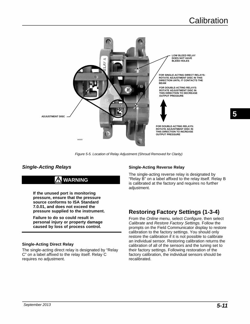
Calibration
September 2013 5-11
Figure 5-5. Location of Relay Adjustment (Shroud Removed for Clarity)
ADJUSTMENT DISC
FOR DOUBLE-ACTING RELAYS:ROTATE ADJUSTMENT DISC INTHIS DIRECTION TO INCREASEOUTPUT PRESSURE
FOR DOUBLE-ACTING RELAYS:ROTATE ADJUSTMENT DISC INTHIS DIRECTION TO DECREASEOUTPUT PRESSURE
FOR SINGLE-ACTING DIRECT RELAYS:ROTATE ADJUSTMENT DISC IN THISDIRECTION UNTIL IT CONTACTS THEBEAM
LOW BLEED RELAYDOES NOT HAVE BLEED HOLES
W9305
Single-Acting Relays
WARNING
If the unused port is monitoringpressure, ensure that the pressuresource conforms to ISA Standard7.0.01, and does not exceed thepressure supplied to the instrument.
Failure to do so could result inpersonal injury or property damagecaused by loss of process control.
Single-Acting Direct RelayThe single-acting direct relay is designated by “RelayC” on a label affixed to the relay itself. Relay Crequires no adjustment.
Single-Acting Reverse Relay
The single-acting reverse relay is designated by“Relay B” on a label affixed to the relay itself. Relay Bis calibrated at the factory and requires no furtheradjustment.
Restoring Factory Settings (1-3-4) From the Online menu, select Configure, then selectCalibrate and Restore Factory Settings. Follow theprompts on the Field Communicator display to restorecalibration to the factory settings. You should onlyrestore the calibration if it is not possible to calibratean individual sensor. Restoring calibration returns thecalibration of all of the sensors and the tuning set totheir factory settings. Following restoration of thefactory calibration, the individual sensors should berecalibrated.
5

DVC6000 SIS
September 20135-12
PST Calibration (1-3-5)Access PST Calibration by selecting PST Calibrationfrom the Calibrate menu. Follow the prompts on theField Communicator display to complete the PSTcalibration.
This procedure permits you to run the Partial StrokeCalibration, which enables the Partial Stroke Test. Itestablishes values for Partial Stroke Pressure Limit,Pressure Set Point and Pressure Saturation Time forEnd Point Pressure Control, Travel Deviation AlertPoint and Travel Deviation Time. The Partial StrokeCalibration also sets default values for max travelmovement, test speed, and test pause time.
NoteYou must take the instrument out ofservice before running Partial StrokeCalibration.
Ensure that the instrument is put backin service after the completing thecalibration procedure.
5
Viewing Device Variables and Diagnostics
September 2013 6-1
6-6
Section 6 Viewing Device Variables and Diagnostics
Service Tools 6-2. . . . . . . . . . . . . . . . . . . . . . . . . . . . . . . . . . . . . . . . . . . . . . . . . . . . . . . . . . . .
Alert Conditions 6-2. . . . . . . . . . . . . . . . . . . . . . . . . . . . . . . . . . . . . . . . . . . . . . . . . . . . . . . . . .
Status 6-3. . . . . . . . . . . . . . . . . . . . . . . . . . . . . . . . . . . . . . . . . . . . . . . . . . . . . . . . . . . . . . . . . . .
Device Record 6-4. . . . . . . . . . . . . . . . . . . . . . . . . . . . . . . . . . . . . . . . . . . . . . . . . . . . . . . . . . .
Stroke Valve 6-4. . . . . . . . . . . . . . . . . . . . . . . . . . . . . . . . . . . . . . . . . . . . . . . . . . . . . . . . . . . . .
Partial Stroke Test 6-4. . . . . . . . . . . . . . . . . . . . . . . . . . . . . . . . . . . . . . . . . . . . . . . . . . . . . . .
Additional SIS Diagnostics 6-6. . . . . . . . . . . . . . . . . . . . . . . . . . . . . . . . . . . . . . . . . . . . . . .Manual Reset 6-6. . . . . . . . . . . . . . . . . . . . . . . . . . . . . . . . . . . . . . . . . . . . . . . . . . . . . . . . . . .Demand Mode Tests 6-6. . . . . . . . . . . . . . . . . . . . . . . . . . . . . . . . . . . . . . . . . . . . . . . . . . . . .Solenoid Valve Health Monitoring 6-7. . . . . . . . . . . . . . . . . . . . . . . . . . . . . . . . . . . . . . . . . .
Overview 6-8. . . . . . . . . . . . . . . . . . . . . . . . . . . . . . . . . . . . . . . . . . . . . . . . . . . . . . . . . . . . . . . . .
Analog Input 6-8. . . . . . . . . . . . . . . . . . . . . . . . . . . . . . . . . . . . . . . . . . . . . . . . . . . . . . . . . . . . .
Travel Set Point 6-8. . . . . . . . . . . . . . . . . . . . . . . . . . . . . . . . . . . . . . . . . . . . . . . . . . . . . . . . . . .
Travel 6-8. . . . . . . . . . . . . . . . . . . . . . . . . . . . . . . . . . . . . . . . . . . . . . . . . . . . . . . . . . . . . . . . . . . .
Drive Signal 6-8. . . . . . . . . . . . . . . . . . . . . . . . . . . . . . . . . . . . . . . . . . . . . . . . . . . . . . . . . . . . .
Pressures 6-8. . . . . . . . . . . . . . . . . . . . . . . . . . . . . . . . . . . . . . . . . . . . . . . . . . . . . . . . . . . . . . .
Variables 6-8. . . . . . . . . . . . . . . . . . . . . . . . . . . . . . . . . . . . . . . . . . . . . . . . . . . . . . . . . . . . . . . .
Device Information 6-9. . . . . . . . . . . . . . . . . . . . . . . . . . . . . . . . . . . . . . . . . . . . . . . . . . . . . . .
DD Information 6-9. . . . . . . . . . . . . . . . . . . . . . . . . . . . . . . . . . . . . . . . . . . . . . . . . . . . . . . . . .
6
DVC6000 SIS
September 20136-2
Service Tools
Alert Conditions (2-1)Instrument Alert Conditions, when enabled, detectmany operational and performance issues that may beof interest. To view these alerts, from the Online menuselect Service Tools and Alert Conditions. The alertconditions for each group of alerts are listed below. Ifthere are no alerts active for a particular group thegroup will not be displayed on the FieldCommunicator.
� Electronics— If an electronics alert is active itwill appear under ELECT ALERTS.
Drive CurrentDrive Current Alert—This alert is indicated when the
drive current does not read as expected. If this alertoccurs, check the connection between the I/Pconverter and the printed wiring board assembly. Tryremoving the I/P converter and re-installing it. If thefailure does not clear, replace the I/P converter or theprinted wiring board assembly.
Drive SignalDrive Signal Alert—This alert is indicated when the
Drive Signal is greater or less than the expectedmaximum or minimum.
Processor ImpairedOffline/Failed Alert—This alert is indicated if a
failure, enabled from the Self Test Shutdown menu,caused an instrument shutdown. Press Enter to seewhich of the specific failures caused the Offline/Failedindication.
Low Power Write Fail Alert—This alert is activated ifa write to the instrument is attempted when the loopcurrent is less than approximately 3.5 mA.
Non-Critical NVM Alert—This alert is indicated if thechecksum for data, which are not critical for instrumentoperation, has failed.
Critical NVM Alert—This alert is indicated when theNon-Volatile Memory integrity test fails. Configurationdata is stored in NVM. If this failure is indicated,restart the instrument and see if it clears. If it does notclear, replace the PWB Assembly.
Flash ROM Alert—This alert indicates that the ReadOnly Memory integrity test failed. If this alert isindicated, restart the instrument and see if it clears. Ifit does not clear, replace the printed wiring boardassembly.
No Free Time Alert—This alert is indicated if theinstrument is unable to complete all of the configuredtasks. This will not occur with a properly functioninginstrument.
Reference Voltage Alert—This failure is indicatedwhenever there is a failure associated with the internalvoltage reference. If this alert is indicated, restart theinstrument and see if it clears. If it does not clear,replace the printed wiring board assembly.
Internal Sensor Out of Limits—This alert is indicatedif there is a possible problem with either the pressuresensor or the printed wiring board assemblysubmodule.
Variable Out of Range—This alert is indicated ifthere is a possible problem with one or more of thefollowing: the Analog Input Signal, the I/P convertersubmodule, the pneumatic relay submodule, or theprinted wiring board.
Field device malfunction—The alert is indicated ifthe pressure, position, or temperature sensors areproviding invalid readings.
� Sensor— If a sensor alert is active it will appearunder SENSOR ALERTS.
Travel SensorTravel Sensor Alert—This alert is indicated if the
sensed travel is outside the range of −25.0 to 125.0%of calibrated travel. If this alert is indicated, check theinstrument mounting and the travel sensor adjustment.Also, check that the electrical connection from thetravel sensor is properly plugged into the printed wiringboard assembly. After restarting the instrument, if thealert does not clear, troubleshoot the printed wiringboard assembly or travel sensor.
Pressure SensorsPressure Sensor Alert—This alert is indicated if the
actuator pressure is outside the range of −24.0 to125.0% of the calibrated pressure for more than 60seconds. If this alert is indicated, check the instrumentsupply pressure. If the failure persists, ensure theprinted wiring board assembly is properly mountedonto the Module Base Assembly, and the pressuresensor O-rings are properly installed. If the alert doesnot clear after restarting the instrument, replace theprinted wiring board assembly.
NoteThe pressure sensor alert is used foroutput A, output B, and the supplypressure sensor. Check the pressurevalues to see which sensor is causingthe alert.
Temperature Sensor Temperature Sensor Alert—This alert is indicated
when the instrument temperature sensor fails, or the
6
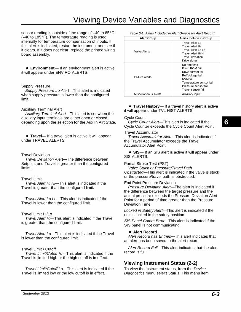
Viewing Device Variables and Diagnostics
September 2013 6-3
sensor reading is outside of the range of −40 to 85�C(−40 to 185�F). The temperature reading is usedinternally for temperature compensation of inputs. Ifthis alert is indicated, restart the instrument and see ifit clears. If it does not clear, replace the printed wiringboard assembly.
� Environment— If an environment alert is activeit will appear under ENVIRO ALERTS.
Supply PressureSupply Pressure Lo Alert—This alert is indicated
when supply pressure is lower than the configuredlimit.
Auxiliary Terminal AlertAuxiliary Terminal Alert—This alert is set when the
auxiliary input terminals are either open or closed,depending upon the selection for the Aux In Alrt State.
� Travel— If a travel alert is active it will appearunder TRAVEL ALERTS.
Travel DeviationTravel Deviation Alert—The difference between
Setpoint and Travel is greater than the configuredlimits.
Travel LimitTravel Alert Hi Hi—This alert is indicated if the
Travel is greater than the configured limit.
Travel Alert Lo Lo—This alert is indicated if theTravel is lower than the configured limit.
Travel Limit Hi/LoTravel Alert Hi—This alert is indicated if the Travel
is greater than the configured limit.
Travel Alert Lo—This alert is indicated if the Travelis lower than the configured limit.
Travel Limit / CutoffTravel Limit/Cutoff Hi—This alert is indicated if the
Travel is limited high or the high cutoff is in effect.
Travel Limit/Cutoff Lo—This alert is indicated if theTravel is limited low or the low cutoff is in effect.
Table 6-1. Alerts Included in Alert Groups for Alert RecordAlert Group Alerts Include in Group
Valve Alerts
Travel Alert LoTravel Alert HiTravel Alert Lo LoTravel Alert Hi HiTravel deviationDrive signal
Failure Alerts
No free timeFlash ROM failDrive current failRef Voltage failNVM failTemperature sensor failPressure sensor failTravel sensor fail
Miscellaneous Alerts Auxiliary input
� Travel History— If a travel history alert is activeit will appear under TVL HIST ALERTS.
Cycle CountCycle Count Alert—This alert is indicated if the
Cycle Counter exceeds the Cycle Count Alert Point.
Travel Accumulator Travel Accumulator Alert—This alert is indicated if
the Travel Accumulator exceeds the TravelAccumulator Alert Point.
� SIS— If an SIS alert is active it will appear underSIS ALERTS.
Partial Stroke Test (PST)Valve Stuck or Pressure/Travel Path
Obstructed—This alert is indicated if the valve is stuckor the pressure/travel path is obstructed.
End Point Pressure DeviationPressure Deviation Alert—The alert is indicated if
the difference between the target pressure and theactual pressure exceeds the Pressure Deviation AlertPoint for a period of time greater than the PressureDeviation Time.
Locked in Safety Alert—This alert is indicated if theunit is locked in the safety position.
SIS Panel Comm Error—This alert is indicated if theSIS panel is not communicating.
� Alert RecordAlert Record has Entries—This alert indicates that
an alert has been saved to the alert record.
Alert Record Full—This alert indicates that the alertrecord is full.
Viewing Instrument Status (2-2)To view the instrument status, from the DeviceDiagnostics menu select Status. This menu item
6
DVC6000 SIS
September 20136-4
indicates the status of the Operational items listedbelow. The status of more than one operational itemmay be indicated.
Instrument Time
Instrument Time Invalid
Calibration and Diagnostics
Calibration in Progress
Autocal in Progress
Diagnostic in Progress
Diagnostic Data Available
Operational
Pressure Control Active
Multi-Drop
Integrator
Integrator Sat Hi
Integrator Sat Lo
Device Record (2-3)From the Online menu, select Service Tools andDevice Record. Follow the prompts on the FieldCommunicator display to view the following DeviceRecord parameters:
� Maximum Recorded Temperature—Shows themaximum temperature the instrument has experiencedsince installation.
� Minimum Recorded Temperature—Shows theminimum temperature the instrument has experiencedsince installation.
� View Number of Days Powered Up—Indicatesin hours or days the total elapsed time the instrumenthas been powered up.
� Number of Power Ups—Indicates how manytimes the instrument has cycled power.
Stroking the Digital Valve ControllerOutput (2-4) From the Online menu, select Service Tools andStroke Valve. Follow the prompts on the FieldCommunicator display to select from the following:
� Done—Select this if you are done. All ramping isstopped when DONE is selected.
� Ramp Open—ramps the travel toward open atthe rate of 1.0% per second of the ranged travel.
� Ramp Closed—ramps the travel toward closed atthe rate of 1.0% per second of the ranged travel.
� Ramp to Target—ramps the travel to thespecified target at the rate of 1.0% per second of theranged travel.
� Step to Target—steps the travel to the specifiedtarget.
Partial Stroke Test (2-5)
WARNING
During the partial stroke test the valvewill move. To avoid personal injuryand property damage caused by therelease of pressure or process fluid,when used in an application wherethe valve is normally closed, providesome temporary means of control forthe process.
The Partial Stroke Test allows the DVC6000 SISdigital valve controller to perform a Valve Signaturetype of test while the instrument is in service andoperational. In SIS applications, it is important to beable to exercise and test the valve to verify that it willoperate when commanded. This feature allows theuser to partially stroke the valve while continuallymonitoring the input signal. If a demand arises, thetest is aborted and the valve moves to its commandedposition. The partial stroke valve travel is configurablebetween 1 and 30% maximum travel, in 0.1%increments. Data from the last partial stroke test isstored in the instrument memory for retrieval byValveLink software.
The Partial Stroke Test allows you to perform a partial,10%, stroke test (standard) or a custom stroke test.With the custom stroke test, the stroke may beextended up to 30%. Be sure to check plant guidelinesbefore performing a custom stroke test. The purposeof this test is to ensure that the valve assembly movesupon demand.
A partial stroke test can be initiated when the valve isoperating at either 4 mA or 20 mA (point-to-pointmode). In applications where a spurious trip is to beminimized, 4 mA is the normal operating position.
When enabled, a partial stroke test may be initiated bythe device (as a scheduled, auto partial stroke test), aremote push button located in the field or at the valve,the optional LCP100 local control panel, the FieldCommunicator, or ValveLink software.
6
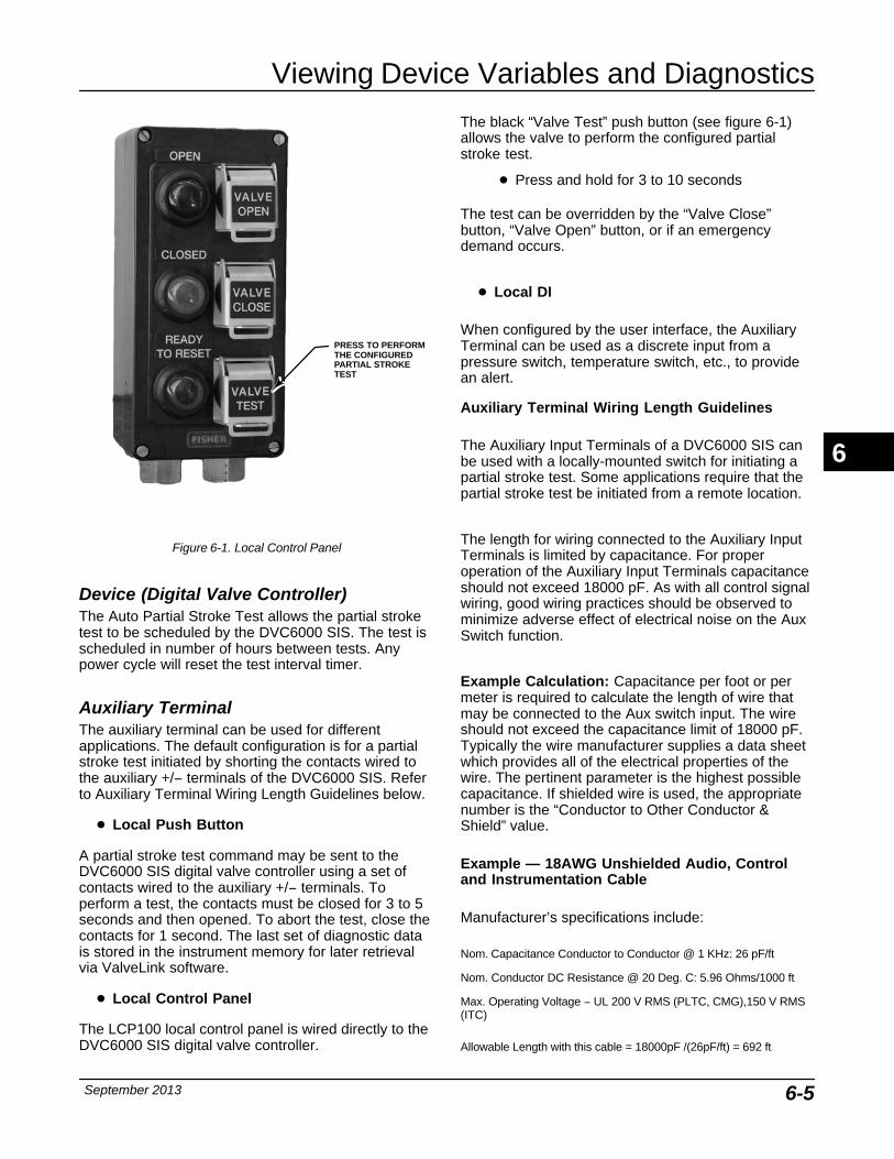
Viewing Device Variables and Diagnostics
September 2013 6-5
PRESS TO PERFORMTHE CONFIGUREDPARTIAL STROKETEST
Figure 6-1. Local Control Panel
Device (Digital Valve Controller)The Auto Partial Stroke Test allows the partial stroketest to be scheduled by the DVC6000 SIS. The test isscheduled in number of hours between tests. Anypower cycle will reset the test interval timer.
Auxiliary TerminalThe auxiliary terminal can be used for differentapplications. The default configuration is for a partialstroke test initiated by shorting the contacts wired tothe auxiliary +/− terminals of the DVC6000 SIS. Referto Auxiliary Terminal Wiring Length Guidelines below.
� Local Push Button
A partial stroke test command may be sent to theDVC6000 SIS digital valve controller using a set ofcontacts wired to the auxiliary +/− terminals. Toperform a test, the contacts must be closed for 3 to 5seconds and then opened. To abort the test, close thecontacts for 1 second. The last set of diagnostic datais stored in the instrument memory for later retrievalvia ValveLink software.
� Local Control Panel
The LCP100 local control panel is wired directly to theDVC6000 SIS digital valve controller.
The black “Valve Test” push button (see figure 6-1)allows the valve to perform the configured partialstroke test.
� Press and hold for 3 to 10 seconds
The test can be overridden by the “Valve Close”button, “Valve Open” button, or if an emergencydemand occurs.
� Local DI
When configured by the user interface, the AuxiliaryTerminal can be used as a discrete input from apressure switch, temperature switch, etc., to providean alert.
Auxiliary Terminal Wiring Length Guidelines
The Auxiliary Input Terminals of a DVC6000 SIS canbe used with a locally-mounted switch for initiating apartial stroke test. Some applications require that thepartial stroke test be initiated from a remote location.
The length for wiring connected to the Auxiliary InputTerminals is limited by capacitance. For properoperation of the Auxiliary Input Terminals capacitanceshould not exceed 18000 pF. As with all control signalwiring, good wiring practices should be observed tominimize adverse effect of electrical noise on the AuxSwitch function.
Example Calculation: Capacitance per foot or permeter is required to calculate the length of wire thatmay be connected to the Aux switch input. The wireshould not exceed the capacitance limit of 18000 pF.Typically the wire manufacturer supplies a data sheetwhich provides all of the electrical properties of thewire. The pertinent parameter is the highest possiblecapacitance. If shielded wire is used, the appropriatenumber is the “Conductor to Other Conductor &Shield” value.
Example — 18AWG Unshielded Audio, Controland Instrumentation Cable
Manufacturer’s specifications include:
Nom. Capacitance Conductor to Conductor @ 1 KHz: 26 pF/ft
Nom. Conductor DC Resistance @ 20 Deg. C: 5.96 Ohms/1000 ft
Max. Operating Voltage − UL 200 V RMS (PLTC, CMG),150 V RMS(ITC)
Allowable Length with this cable = 18000pF /(26pF/ft) = 692 ft
6
DVC6000 SIS
September 20136-6
Example — 18AWG Shielded Audio, Control andInstrumentation Cable
Manufacturer’s specifications include:
Nom. Characteristic Impedance: 29 Ohms
Nom. Inductance: .15 μH/ft
Nom. Capacitance Conductor to Conductor @ 1 KHz: 51 pF/ft
Nom. Cap. Cond. to other Cond. & Shield @ 1 KHz 97 pF/ft
Allowable Length with this cable = 18000pF /(97pF/ft) = 185 ft
The AUX switch input passes less than 1 mA throughthe switch contacts, and uses less than 5V, therefore,neither the resistance nor the voltage rating of thecable are critical. Ensure that switch contact corrosionis prevented. It is generally advisable that the switchhave gold-plated or sealed contacts.
Field Communicator1. Connect the Field Communicator to the LOOPterminals on the digital valve controller.
2. Turn on the Field Communicator.
3. From the Online menu, select Service Tools andPartial Stroke Test.
4. Select either Standard (10%) or Custom. With theCustom Stroke Test, the stroke may be entered up to30% with configurable stroking speed and pause time.
5. The currently configured Stroke, Stroking Speed,and Pause Time is displayed. Choose “Yes” to run thetest using these values. Choose “No” to modify thevalues. The default value for Stroke Speed is0.25%/second.
6. The valve begins to move and the actual travelreported by the digital valve controller is displayed onthe Field Communicator.
7. Observe the valve as it runs the Partial Stroke Testto verify that it moves to the desired setpoint and thenreturns to the original position.
For information on configuring the Partial Stroke Test,see Partial Stroke Variables in the Detailed Setupsection.
Additional SIS Diagnostics
Manual ResetThe DVC6000 SIS digital valve controller can beconfigured to hold the trip state until a local resetbutton is pressed. It is configurable by the FieldCommunicator or ValveLink software. Manual Resetcan be initiated by shorting the AUX terminals with auser-supplied push button for at least 3 seconds, butless than 5 seconds or by pressing the button next to
the green light on the optional LCP100 local controlpanel when the current is at it’s normal state. Thedigital valve controller will drive the valve to its normaloperating position.
Demand Mode TestsThe following steps assume the use of single actingspring and diaphragm actuators or double-actingspring assist piston actuators.
Perform the following steps to confirm valve operation:
a. Point-to-Point Mode (DVC6000 SIS powered with 4−20 mA current source)
If the DVC6000 SIS is in series with a solenoid valve,
1. Disconnect the power from the solenoid valve,but maintain the 20 mA current to the digital valvecontroller. The valve should move to its “fail safe”position.
2. Maintain power to the solenoid valve and adjustthe current to the digital valve controller from 20 mA to 4mA. The valve should move to its “failsafe” position.
3. Remove power from the solenoid valve andadjust the current to the digital valve controllerfrom 20mA to 4mA. The valve should go to its “failsafe” position.
If a solenoid is not used with a DVC6000 SIS,
1. Adjust the current to the digital valve controllerfrom 20 mA to 4 mA. The valve should move to its“fail safe” position.
NoteThe above tests are applicable forsingle-acting direct relay A and C. Ifsingle-acting reverse relay B is usedadjust the current from 4 mA (normalstate) to 20 mA (trip state).
b. Multi-drop Mode (DVC6000 SIS is powered by a 24 VDC power source)
If the DVC6000 SIS is pneumatically in series with asolenoid valve, and shares a single power source,
Disconnect power to both devices. The valveshould go to its “fail safe” position.
If the DVC6000 SIS is pneumatically in series with asolenoid valve, with independent power sources,
6
Viewing Device Variables and Diagnostics
September 2013 6-7
Connect a 24 VDC power supply to the solenoidvalve and a second 24 VDC power supply to theDVC6000 SIS. Disconnect the solenoid valvepower supply, but maintain the power supply tothe DVC6000 SIS. The valve should go to its “failsafe” position quickly. Then, maintain the powersupply to the solenoid valve and disconnect theDVC6000 SIS power supply. The valve should goto its “fail safe” position, although not as quickly asit does in the previous scenario.
If DVC6000 SIS is alone, without a solenoid valve,
Disconnect power to the digital valve controller.The valve should go to its “fail safe” position.
NoteThe above tests are not applicable forsingle-acting reverse relay B when nosolenoid valve is present.
If the LCP100 is used, conduct the following tests:
Successful Partial Stroke Test
1. Press the “Valve Test” (black) push button formore than 3 seconds (but less than 10 seconds).
2. Observe that the green light starts flashingwhen the valve starts moving.
3. Observe that the valve moves no more thanthe configured PST travel limit.
4. Observe that the valve returns to the normaloperating position and the green light comes onsolid.
Manually Aborted Partial Stroke Test
1. Press the “Valve Test” (black) push button formore than 3 seconds (but less than 10 seconds).
2. Observe that the green light starts flashingwhen the valve starts moving.
3. Before the valve reaches the travel limit of theconfigured partial stroke test, press the “ValveTest” push button, or the push button next to thegreen light.
4. Observe that the valve immediately returns tothe normal operating position and the green lightcomes on solid.
Emergency Demand through the Logic Solver
1. Reduce the current to the DVC6000 to 4 mAfor de-energize to trip operation.
NoteYou may remove the powercompletely; however, the lights in step 3 will be off. Without power to theDVC6000 SIS, the LCP100 cannotfunction.
2. Observe that the valve moves to its fail safestate.
3. Observe that the red light comes on solid andthe amber light stays off (valve is not ready toopen).
4. Press the push button next to the green lightand observe that the valve does not move.
5. Increase the current to the DVC6000 to 20 mAand observe that the valve remains in its fail safestate.
6. Observe that the red light stays on solid andthe amber light comes on solid (ready to reset).
7. Press the push button next to the green light.
8. Observe that the green light starts flashing,then becomes solid and the red light is off.
Emergency Demand through Local Control Panel
1. Press the push button next to the red light.
2. Observe that the valve moves to it fail safeposition.
3. Observe that the red light starts flashing, thenbecomes solid and the amber light comes on solid(ready to reset).
4. Press the push button next to the green light.
5. Observe that the red light goes off, the valvemoves to its normal operating position, and thegreen light comes on solid.
Solenoid Valve Health MonitoringThe following steps assume the use of a single-actingactuator with a solenoid valve installed. The DVC6000SIS digital valve controller, with single-acting, directrelay C, must be powered separately from thesolenoid. The unused output of the DVC6000 SISmust be connected between the solenoid and theactuator as described in the Installation section. Therelay configuration selection must be “specialapplication” and ValveLink Software must have thetriggered profile enabled.
6
DVC6000 SIS
September 20136-8
1. When allowed by the Logic Solver, momentarilyremove and then restore power to the solenoid(typically 100 to 200 milliseconds). This processshould occur quickly enough that the valve assemblydoes not move when the solenoid is de-energized.
2. With ValveLink Software, upload the diagnosticdata from the triggered profile menu.
3. Examine the graph and observe that there was achange in the pressure reading downstream of thesolenoid.
Overview The following menus are available to define and/orview information about the instrument. SelectOverview from the Online menu.
Analog In (3-1)—Analog Input shows the value of theinstrument analog input in mA (milliamperes) or %(percent) of ranged input.
Set Point (3-2)—Travel Set Point shows therequested valve position in % of ranged travel.
Travel (3-3)—Travel shows the value of the DVC6000SIS digital valve controller travel in % (percent) ofranged travel. Travel always represents how far thevalve is open.
Drive Signal (3-4)—Drive Signal shows the value ofthe instrument drive signal in % (percent) of maximumdrive.
Pressure (3-5)
Shows the value of the instrument supply and outputpressures in psi, bar, kPa, or kg/cm2. Also shows theoutput pressure differential. To display pressures mayrequire selecting the variable; a detail display of thatvariable with its values will appear.
� Pressure A—Shows the value of OutputPressure A in psi, bar, kPa, or kg/cm2.
� Pressure B—Shows the value of OutputPressure A in psi, bar, kPa, or kg/cm2.
� A Minus B—Shows the value of the outputpressure differential in psi, bar, kPa, or kg/cm2.
� Supply—Displays the instrument supplypressure in psi, bar, kPa, or kg/cm2.
Variables (3-6)
The Variables menu is available to view additionalvariables, including; Auxiliary Input, Temperature,Maximum Recorded Temperature, Minimum RecordedTemperature, Cycle Counter, Travel Accumulator,Raw Travel Input, View Number of Days Powered Up,and Number of Power Ups.
To view one of these variables, from the Online menuselect Overviews and Variables. If a value for avariable does not appear on the display, select thevariable and a detailed display of that variable with itsvalue will appear. A variable’s value does not appearon the menu if the value becomes too large to fit in theallocated space on the display, or if the variablerequires special processing, such as Aux Input.
� Auxiliary Input—A discrete input that can beused with an independent limit or pressure switch. Itsvalue is either open or closed.
� Temperature—The internal temperature of theinstrument is displayed in either degrees Fahrenheit orCelsius.
� Maximum Recorded Temperature—Shows themaximum temperature the instrument has experiencedsince installation.
� Minimum Recorded Temperature—Shows theminimum temperature the instrument has experiencedsince installation.
� Cycle Counter—Displays the number of timesthe valve travel has cycled. Only changes in directionof the travel after the travel has exceeded thedeadband are counted as a cycle. Once a new cyclehas occurred, a new deadband around the last travelis set. The value of the Cycle Counter can be resetfrom the Cycle Count Alert menu. See page 4-16 ofthe Detailed Setup section for additional information.
� Travel Accumulator—Contains the total changein travel, in percent of ranged travel. The accumulatoronly increments when travel exceeds the deadband.Then the greatest amount of change in one directionfrom the original reference point (after the deadbandhas been exceeded) will be added to the TravelAccumulator. The value of the Travel Accumulator canbe reset from the Travel Accumulator menu. See page4-16 of the Detailed Setup section for additionalinformation.
6
Viewing Device Variables and Diagnostics
September 2013 6-9
NoteDo not use the following raw travelinput indication for calibrating thetravel sensor. The following shouldonly be used for a relative indication tobe sure the travel sensor is workingand that it is moving in the correctdirection. Perform the Travel SensorAdjust procedure in the Calibrationsection to calibrate the travel sensor.
� Raw Travel Input—Raw travel input indicatesthe travel sensor position in analog-to-digital convertercounts. When the travel sensor is operating correctly,this number changes as the valve strokes.
� View Number of Days Powered Up—Indicatesin hours or days the total elapsed time the instrumenthas been powered up.
� Number of Power Ups—Indicates how manytimes the instrument has cycled power.
Device Information (3-7)
The Device Information menu is available to viewinformation about the instrument. From the Onlinemenu, select Overview and Device Information. Followthe prompts on the Field Communicator display toview information in the following fields:
� Hart Tag—A HART tag is a unique name (up toeight characters) that identifies the physicalinstrument.
� Device ID—Each instrument has a uniqueDevice Identifier. The device ID provides additionalsecurity to prevent this instrument from acceptingcommands meant for other instruments.
Table 6-2. Functions Available for Instrument LevelFunctions Available
Communicates with Field Communicator and ValveLink software.Provides: travel cutoffs and limits, minimum opening and closingtimes, input characterization (linear, equal percentage, quick opening,and custom), trending with ValveLink Solo, and the following alerts:travel deviation; travel alert high, low, high high, and low low; drivesignal; auxiliary terminal; cycle counter; and travel accumulation. WithValveLink Software, all offline diagnostic tests (dynamic error band,drive signal, step response, and valve signature) plus online trendingand partial stroke test
� Manufacturer—Identifies the manufacturer ofthe instrument.
� Model—Identifies the instrument model.
� Device Revision—The revision number of thesoftware for communication between the FieldCommunicator and the instrument.
� Firmware Revision—The revision number of thefirmware in the instrument.
� Hardware Revision—The revision number of theelectrical circuitry within the instrument printed wiringboard.
� Instrument Level—Indicates the instrumentlevel − SIS
Table 6-2 lists the functions available instrument levelSIS.
� HART Univeral Revision—The revision numberof the HART Universal Commands which are used asthe communications protocol for the instrument.
DD Information (3-8)—DD Information contains thedevice description in the Field Communicator. Toaccess DD Information from the Online menu, selectOverview and DD Information.
6
DVC6000 SIS
September 20136-10
6
Maintenance and Troubleshooting
September 2013 7-1
7-7
Section 7 Maintenance and Troubleshooting
Module Base MaintenanceRemoving the Module Base 7-4. . . . . . . . . . . . . . . . . . . . . . . . . . . . . . . . . . . . . . . . . . . . . .
Replacing the Module Base 7-4. . . . . . . . . . . . . . . . . . . . . . . . . . . . . . . . . . . . . . . . . . . . . .
Submodule MaintenanceI/P Converter
Removing the I/P Converter 7-6. . . . . . . . . . . . . . . . . . . . . . . . . . . . . . . . . . . . . . . . . . . . . . .Replacing the I/P Converter 7-6. . . . . . . . . . . . . . . . . . . . . . . . . . . . . . . . . . . . . . . . . . . . . . .
Printed Wiring Board (PWB) AssemblyRemoving the Printed Wiring Board Assembly 7-6. . . . . . . . . . . . . . . . . . . . . . . . . . . . . . .Replacing the Printed Wiring Board Assembly 7-6. . . . . . . . . . . . . . . . . . . . . . . . . . . . . . . .Setting the Printed Wiring Board Switch 7-6. . . . . . . . . . . . . . . . . . . . . . . . . . . . . . . . . . . . .
Pneumatic RelayRemoving the Pneumatic Relay 7-7. . . . . . . . . . . . . . . . . . . . . . . . . . . . . . . . . . . . . . . . . . . .Replacing the Pneumatic Relay 7-7. . . . . . . . . . . . . . . . . . . . . . . . . . . . . . . . . . . . . . . . . . . .
Gauges, Pipe Plugs or Tire Valves 7-8. . . . . . . . . . . . . . . . . . . . . . . . . . . . . . . . . . . . . . .
Terminal BoxRemoving the Terminal Box 7-8. . . . . . . . . . . . . . . . . . . . . . . . . . . . . . . . . . . . . . . . . . . . . .
Replacing the Terminal Box 7-8. . . . . . . . . . . . . . . . . . . . . . . . . . . . . . . . . . . . . . . . . . . . . .
Travel SensorDisassembly
DVC6010 SIS Digital Valve Controller and DVC6015 RemoteFeedback Unit (Sliding-Stem) 7-9. . . . . . . . . . . . . . . . . . . . . . . . . . . . . . . . . . . . . . . . . . . .
DVC6020 SIS Digital Valve Controller and DVC6025 RemoteFeedback Unit (Rotary) 7-9. . . . . . . . . . . . . . . . . . . . . . . . . . . . . . . . . . . . . . . . . . . . . . . . .
DVC6030 SIS Digital Valve Controller and DVC6035 Remote Feedback Unit (Rotary) 7-10. . . . . . . . . . . . . . . . . . . . . . . . . . . . . . . . . . . . . . . . . . . . . . . . .
AssemblyDVC6010 SIS Digital Valve Controller and DVC6015 Remote
Feedback Unit (Sliding-Stem) 7-10. . . . . . . . . . . . . . . . . . . . . . . . . . . . . . . . . . . . . . . . . . . .DVC6020 SIS Digital Valve Controller and DVC6025 Remote
Feedback Unit (Rotary) 7-12. . . . . . . . . . . . . . . . . . . . . . . . . . . . . . . . . . . . . . . . . . . . . . . . .DVC6030 SIS Digital Valve Controller and DVC6035 Remote
Feedback Unit (Rotary) 7-13. . . . . . . . . . . . . . . . . . . . . . . . . . . . . . . . . . . . . . . . . . . . . . . . .
Instrument Troubleshooting 7-14. . . . . . . . . . . . . . . . . . . . . . . . . . . . . . . . . . . . . . . . . . .
Checking Voltage Available 7-14. . . . . . . . . . . . . . . . . . . . . . . . . . . . . . . . . . . . . . . . . . . .
Checking Loop Current 7-15. . . . . . . . . . . . . . . . . . . . . . . . . . . . . . . . . . . . . . . . . . . . . . . . .
7
DVC6000 SIS
September 20137-2
The DVC6000 SIS digital valve controller enclosure israted NEMA 4X and IP66, therefore periodic cleaningof internal components is not required. If the DVC6000SIS is installed in an area where the exterior surfacestend to get heavily coated or layered with industrial oratmospheric contaminants, however, it isrecommended that the vent (key 52) be periodicallyinspected to ensure it is fully open. If the vent appearsto be clogged, the vent can be removed, cleaned andreplaced. Lightly brush the exterior of the vent toremove contaminant and run a mild water/detergentsolution through the vent to ensure it is fully open.
WARNING
Personal injury or property damagecan occur from cover failure due tooverpressure. Ensure that thehousing vent opening is open andfree of debris to prevent pressurebuildup under the cover.
WARNING
To avoid static discharge from theplastic cover when flammable gasesor dust are present, do not rub orclean the cover with solvents. To doso could result in a spark that maycause flammable gases or dust toexplode, resulting in personal injuryor property damage. Clean with a milddetergent and water only.
WARNING
Avoid personal injury or propertydamage from sudden release ofprocess pressure or bursting of parts.Before performing any maintenanceprocedures on the DVC6000 SISdigital valve controller:
� Always wear protective clothing,gloves, and eyewear to preventpersonal injury.
� Do not remove the actuator fromthe valve while the valve is stillpressurized.
� Disconnect any operating linesproviding air pressure, electric power,
or a control signal to the actuator. Besure the actuator cannot suddenly openor close the valve.
� Use bypass valves or completelyshut off the process to isolate the valvefrom process pressure. Relieve processpressure from both sides of the valve.
� Use lock-out procedures to be surethat the above measures stay in effectwhile you work on the equipment.
� Check with your process or safetyengineer for any additional measuresthat must be taken to protect againstprocess media.
� Vent the pneumatic actuatorloading pressure and relieve anyactuator spring precompression so theactuator is not applying force to thevalve stem; this will allow for the saferemoval of the stem connector.
WARNING
When using natural gas as the supplymedium, or for explosion proofapplications, the following warningsalso apply:
� Remove electrical power beforeremoving the housing cap. Personalinjury or property damage from fire orexplosion may result if power is notdisconnected before removing thecap.
� Remove electrical power beforedisconnecting any of the pneumaticconnections.
� When disconnecting any of thepneumatic connections or any pressureretaining part, natural gas will seep fromthe unit and any connected equipmentinto the surrounding atmosphere.Personal injury or property damage mayresult from fire or explosion if naturalgas is used as the supply medium andappropriate preventive measures are nottaken. Preventive measures mayinclude, but are not limited to, one ormore of the following: Remote ventingof the unit, re-evaluating the hazardousarea classification, ensuring adequateventilation, and the removal of anyignition sources. For information onremote venting of this controller, refer topage 2-22.
7
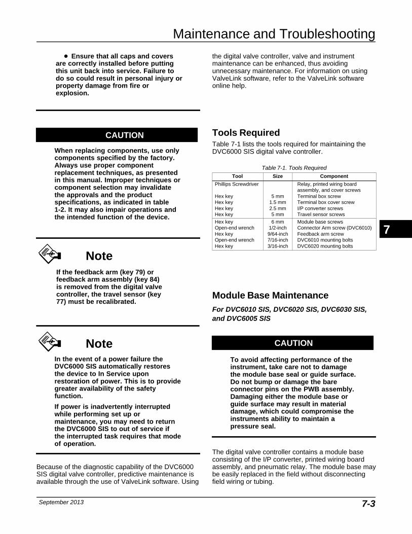
Maintenance and Troubleshooting
September 2013 7-3
� Ensure that all caps and coversare correctly installed before puttingthis unit back into service. Failure todo so could result in personal injury orproperty damage from fire orexplosion.
CAUTION
When replacing components, use onlycomponents specified by the factory.Always use proper componentreplacement techniques, as presentedin this manual. Improper techniques orcomponent selection may invalidatethe approvals and the productspecifications, as indicated in table1-2. It may also impair operations andthe intended function of the device.
NoteIf the feedback arm (key 79) orfeedback arm assembly (key 84)is removed from the digital valvecontroller, the travel sensor (key77) must be recalibrated.
NoteIn the event of a power failure theDVC6000 SIS automatically restoresthe device to In Service uponrestoration of power. This is to providegreater availability of the safetyfunction.
If power is inadvertently interruptedwhile performing set up ormaintenance, you may need to returnthe DVC6000 SIS to out of service ifthe interrupted task requires that modeof operation.
Because of the diagnostic capability of the DVC6000SIS digital valve controller, predictive maintenance isavailable through the use of ValveLink software. Using
the digital valve controller, valve and instrumentmaintenance can be enhanced, thus avoidingunnecessary maintenance. For information on usingValveLink software, refer to the ValveLink softwareonline help.
Tools RequiredTable 7-1 lists the tools required for maintaining theDVC6000 SIS digital valve controller.
Table 7-1. Tools RequiredTool Size Component
Phillips Screwdriver
Hex keyHex keyHex keyHex key
5 mm1.5 mm2.5 mm5 mm
Relay, printed wiring boardassembly, and cover screwsTerminal box screwTerminal box cover screwI/P converter screwsTravel sensor screws
Hex keyOpen-end wrenchHex keyOpen-end wrenchHex key
6 mm1/2-inch9/64-inch7/16-inch3/16-inch
Module base screwsConnector Arm screw (DVC6010)Feedback arm screwDVC6010 mounting boltsDVC6020 mounting bolts
Module Base Maintenance For DVC6010 SIS, DVC6020 SIS, DVC6030 SIS,and DVC6005 SIS
CAUTION
To avoid affecting performance of theinstrument, take care not to damagethe module base seal or guide surface.Do not bump or damage the bareconnector pins on the PWB assembly.Damaging either the module base orguide surface may result in materialdamage, which could compromise theinstruments ability to maintain apressure seal.
The digital valve controller contains a module baseconsisting of the I/P converter, printed wiring boardassembly, and pneumatic relay. The module base maybe easily replaced in the field without disconnectingfield wiring or tubing.
7
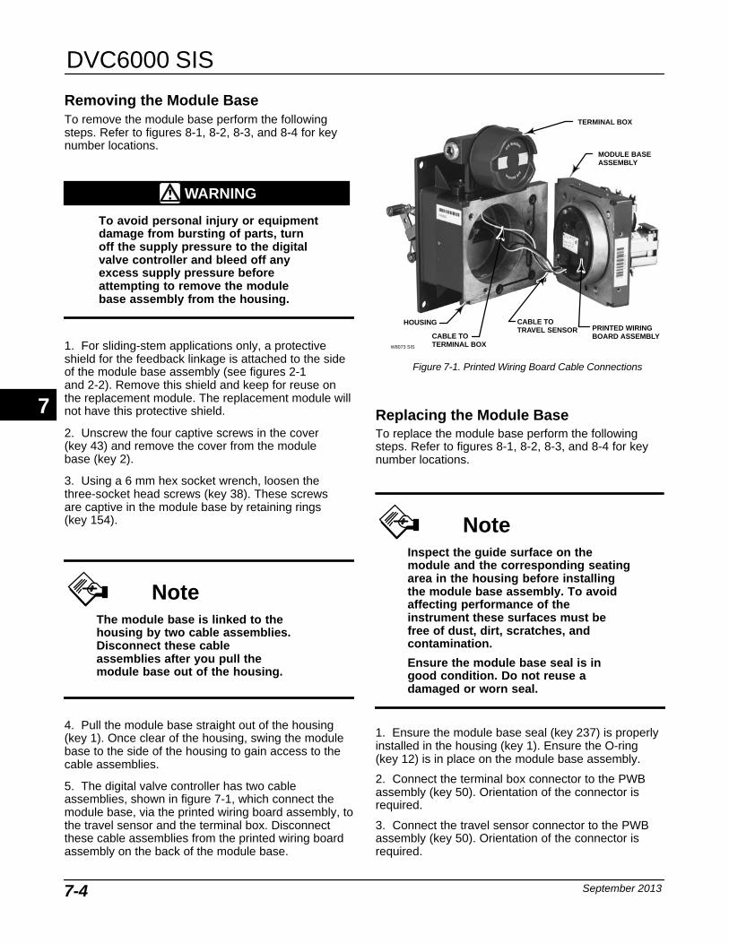
DVC6000 SIS
September 20137-4
Removing the Module Base To remove the module base perform the followingsteps. Refer to figures 8-1, 8-2, 8-3, and 8-4 for keynumber locations.
WARNING
To avoid personal injury or equipmentdamage from bursting of parts, turnoff the supply pressure to the digitalvalve controller and bleed off anyexcess supply pressure beforeattempting to remove the modulebase assembly from the housing.
1. For sliding-stem applications only, a protectiveshield for the feedback linkage is attached to the sideof the module base assembly (see figures 2-1and 2-2). Remove this shield and keep for reuse onthe replacement module. The replacement module willnot have this protective shield.
2. Unscrew the four captive screws in the cover(key 43) and remove the cover from the modulebase (key 2).
3. Using a 6 mm hex socket wrench, loosen thethree-socket head screws (key 38). These screws are captive in the module base by retaining rings (key 154).
NoteThe module base is linked to thehousing by two cable assemblies.Disconnect these cableassemblies after you pull themodule base out of the housing.
4. Pull the module base straight out of the housing(key 1). Once clear of the housing, swing the modulebase to the side of the housing to gain access to thecable assemblies.
5. The digital valve controller has two cableassemblies, shown in figure 7-1, which connect themodule base, via the printed wiring board assembly, tothe travel sensor and the terminal box. Disconnectthese cable assemblies from the printed wiring boardassembly on the back of the module base.
Figure 7-1. Printed Wiring Board Cable Connections
TERMINAL BOX
MODULE BASEASSEMBLY
PRINTED WIRINGBOARD ASSEMBLY
HOUSING
CABLE TOTERMINAL BOXW8073 SIS
CABLE TOTRAVEL SENSOR
Replacing the Module Base To replace the module base perform the followingsteps. Refer to figures 8-1, 8-2, 8-3, and 8-4 for keynumber locations.
NoteInspect the guide surface on themodule and the corresponding seatingarea in the housing before installingthe module base assembly. To avoidaffecting performance of theinstrument these surfaces must be free of dust, dirt, scratches, andcontamination.
Ensure the module base seal is ingood condition. Do not reuse adamaged or worn seal.
1. Ensure the module base seal (key 237) is properlyinstalled in the housing (key 1). Ensure the O-ring (key 12) is in place on the module base assembly.
2. Connect the terminal box connector to the PWBassembly (key 50). Orientation of the connector isrequired.
3. Connect the travel sensor connector to the PWBassembly (key 50). Orientation of the connector isrequired.
7
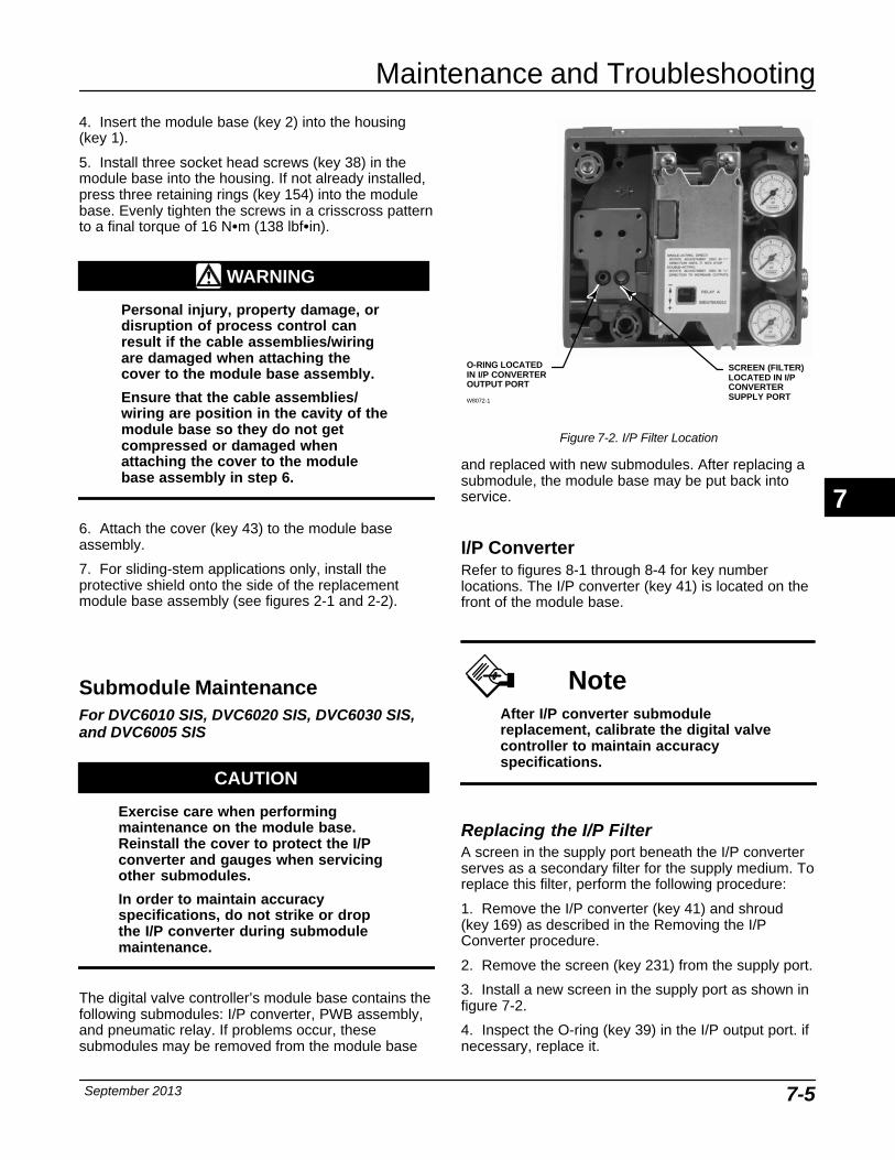
Maintenance and Troubleshooting
September 2013 7-5
4. Insert the module base (key 2) into the housing(key 1).
5. Install three socket head screws (key 38) in themodule base into the housing. If not already installed,press three retaining rings (key 154) into the modulebase. Evenly tighten the screws in a crisscross patternto a final torque of 16 N�m (138 lbf�in).
WARNING
Personal injury, property damage, ordisruption of process control canresult if the cable assemblies/wiringare damaged when attaching thecover to the module base assembly.
Ensure that the cable assemblies/wiring are position in the cavity of themodule base so they do not getcompressed or damaged whenattaching the cover to the modulebase assembly in step 6.
6. Attach the cover (key 43) to the module baseassembly.
7. For sliding-stem applications only, install theprotective shield onto the side of the replacementmodule base assembly (see figures 2-1 and 2-2).
Submodule MaintenanceFor DVC6010 SIS, DVC6020 SIS, DVC6030 SIS,and DVC6005 SIS
CAUTION
Exercise care when performingmaintenance on the module base.Reinstall the cover to protect the I/Pconverter and gauges when servicingother submodules.
In order to maintain accuracyspecifications, do not strike or dropthe I/P converter during submodulemaintenance.
The digital valve controller’s module base contains thefollowing submodules: I/P converter, PWB assembly,and pneumatic relay. If problems occur, thesesubmodules may be removed from the module base
SCREEN (FILTER)LOCATED IN I/PCONVERTERSUPPLY PORT
Figure 7-2. I/P Filter Location
O-RING LOCATEDIN I/P CONVERTEROUTPUT PORT
W8072-1
and replaced with new submodules. After replacing asubmodule, the module base may be put back intoservice.
I/P ConverterRefer to figures 8-1 through 8-4 for key numberlocations. The I/P converter (key 41) is located on thefront of the module base.
NoteAfter I/P converter submodulereplacement, calibrate the digital valvecontroller to maintain accuracyspecifications.
Replacing the I/P Filter A screen in the supply port beneath the I/P converterserves as a secondary filter for the supply medium. Toreplace this filter, perform the following procedure:
1. Remove the I/P converter (key 41) and shroud (key 169) as described in the Removing the I/PConverter procedure.
2. Remove the screen (key 231) from the supply port.
3. Install a new screen in the supply port as shown infigure 7-2.
4. Inspect the O-ring (key 39) in the I/P output port. ifnecessary, replace it.
7
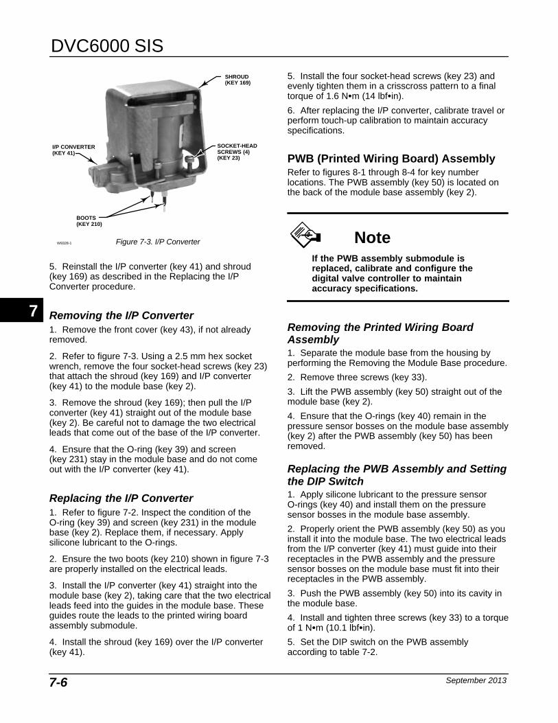
DVC6000 SIS
September 20137-6
Figure 7-3. I/P ConverterW9328-1
SOCKET-HEADSCREWS (4)(KEY 23)
SHROUD(KEY 169)
I/P CONVERTER(KEY 41)
BOOTS(KEY 210)
5. Reinstall the I/P converter (key 41) and shroud (key 169) as described in the Replacing the I/PConverter procedure.
Removing the I/P Converter 1. Remove the front cover (key 43), if not alreadyremoved.
2. Refer to figure 7-3. Using a 2.5 mm hex socketwrench, remove the four socket-head screws (key 23)that attach the shroud (key 169) and I/P converter(key 41) to the module base (key 2).
3. Remove the shroud (key 169); then pull the I/Pconverter (key 41) straight out of the module base(key 2). Be careful not to damage the two electricalleads that come out of the base of the I/P converter.
4. Ensure that the O-ring (key 39) and screen(key 231) stay in the module base and do not comeout with the I/P converter (key 41).
Replacing the I/P Converter 1. Refer to figure 7-2. Inspect the condition of theO-ring (key 39) and screen (key 231) in the modulebase (key 2). Replace them, if necessary. Applysilicone lubricant to the O-rings.
2. Ensure the two boots (key 210) shown in figure 7-3are properly installed on the electrical leads.
3. Install the I/P converter (key 41) straight into themodule base (key 2), taking care that the two electricalleads feed into the guides in the module base. Theseguides route the leads to the printed wiring boardassembly submodule.
4. Install the shroud (key 169) over the I/P converter(key 41).
5. Install the four socket-head screws (key 23) andevenly tighten them in a crisscross pattern to a finaltorque of 1.6 N�m (14 lbf�in).
6. After replacing the I/P converter, calibrate travel orperform touch-up calibration to maintain accuracyspecifications.
PWB (Printed Wiring Board) AssemblyRefer to figures 8-1 through 8-4 for key numberlocations. The PWB assembly (key 50) is located onthe back of the module base assembly (key 2).
NoteIf the PWB assembly submodule isreplaced, calibrate and configure thedigital valve controller to maintainaccuracy specifications.
Removing the Printed Wiring BoardAssembly 1. Separate the module base from the housing byperforming the Removing the Module Base procedure.
2. Remove three screws (key 33).
3. Lift the PWB assembly (key 50) straight out of themodule base (key 2).
4. Ensure that the O-rings (key 40) remain in thepressure sensor bosses on the module base assembly(key 2) after the PWB assembly (key 50) has beenremoved.
Replacing the PWB Assembly and Settingthe DIP Switch 1. Apply silicone lubricant to the pressure sensorO-rings (key 40) and install them on the pressuresensor bosses in the module base assembly.
2. Properly orient the PWB assembly (key 50) as youinstall it into the module base. The two electrical leadsfrom the I/P converter (key 41) must guide into theirreceptacles in the PWB assembly and the pressuresensor bosses on the module base must fit into theirreceptacles in the PWB assembly.
3. Push the PWB assembly (key 50) into its cavity inthe module base.
4. Install and tighten three screws (key 33) to a torqueof 1 N�m (10.1 lbf�in).
5. Set the DIP switch on the PWB assemblyaccording to table 7-2.
7

Maintenance and Troubleshooting
September 2013 7-7
Figure 7-4. DIP Switch Location
BACK OF PWB ASSEMBLYSUB-MODULE
DIP SWITCH
UP
DOWN
TRAVEL SENSORCONNECTOR
TERMINAL BOXCONNECTOR
Table 7-2. DIP Switch Configuration(1)
Operational Mode Switch Position
Multi-drop Loop UP
Point-to-Point LoopDOWN
1. Refer to figure 7-4 for switch location.
NoteFor the digital valve controller tooperate with a 4-20 mA control signal,the DIP switch must be in thepoint-to-point loop position, as shownin table 7-2.
For the digital valve controller tooperate with a 24 VDC voltage controlsignal, the DIP switch must be in themulti-drop loop position, as shown intable 7-2.
6. Reassemble the module base to the housing byperforming the Replacing the Module Base procedure.
7. Setup and calibrate the digital valve controller.
Figure 7-5. Pneumatic Relay AssemblyW8074
RELAY SEAL
Pneumatic RelayRefer to figures 8-1 through 8-4 for key numberlocations. The pneumatic relay (key 24) is located onthe front of the module base.
NoteAfter relay submodule replacement,calibrate the digital valve controller tomaintain accuracy specifications.
Removing the Pneumatic Relay 1. Loosen the four screws that attach the relay (key 24) to the module base. These screws arecaptive in the relay.
2. Remove the relay.
Replacing the Pneumatic Relay 1. Visually inspect the holes in the module base toensure they are clean and free of obstructions. Ifcleaning is necessary, do not enlarge the holes.
2. Apply silicone lubricant to the relay seal andposition it in the grooves on the bottom of the relay asshown in figure 7-5. Press small seal retaining tabsinto retaining slots to hold relay seal in place.
3. Position the relay (with shroud) on the modulebase. Tighten the four screws, in a crisscross pattern,to a final torque of 2 N�m (20.7 lbf�in).
4. Using the Field Communicator, verify that the valuefor Relay Type parameter matches the relay typeinstalled.
5. After replacing the relay and verifying the relaytype, calibrate travel to maintain accuracyspecifications.
7
DVC6000 SIS
September 20137-8
Gauges, Pipe Plugs, or Tire Valves Depending on the options ordered, the DVC6000 SISdigital valve controller will be equipped with eithergauges (key 47), pipe plugs (key 66), or tire valves(key 67). Single-acting direct instruments will alsohave a screen (key 236, figure 8-5). These are locatedon the top of the module base next to the relay.
Perform the following procedure to replace thegauges, tire valves, or pipe plugs. Refer to figures 8-1through 8-5 for key number locations.
1. Remove the front cover (key 43).
2. Remove the gauge, pipe plug, or tire valve asfollows:
For gauges (key 47), the flats are on the gauge case.Use a wrench on the flats of the gauge to remove thegauge from the module base. For double-actinginstruments, to remove the supply gauge remove oneof the output gauges.
For pipe plugs (key 66) and tire valves (key 67),use a wrench to remove these from the module base.
3. Apply anti-seize (key 64) to the threads of thereplacement gauges, pipe plugs, or tire valves.
4. Using a wrench, screw the gauges, pipe plugs, ortire valves into the module base.
Terminal BoxFor DVC6010 SIS, DVC6020 SIS, DVC6030 SIS,and DVC6005 SISRefer to figures 8-1 through 8-4 for key numberlocations.
The terminal box is located on the housing andcontains the terminal strip assembly for field wiringconnections.
NoteThis procedure also applies to theDVC6005 SIS remote terminal box.
Removing the Terminal Box
WARNING
To avoid personal injury or propertydamage caused by fire or explosion,remove power to the instrumentbefore removing the terminal boxcover in an area which contains apotentially explosive atmosphere orhas been classified as hazardous.
1. Loosen the set screw (key 58) in the cap (key 4) sothat the cap can be unscrewed from the terminal box.
2. After removing the cap (key 4), note the location offield wiring connections and disconnect the field wiringfrom the terminal box.
3. Separate the module base from the housing byperforming the Removing the Module Base procedure.
4. Remove the screw (key 72). Pull the terminal boxassembly straight out of the housing.
5. Remove two wire retainers (key 44), internal andexternal to the terminal box.
Replacing the Terminal Box
NoteInspect all O-rings for wear andreplace as necessary.
1. Install two wire retainers (key 44), internal andexternal to the terminal box.
2. Apply silicone lubricant to the O-ring (key 35) andinstall the O-ring over the stem of the terminal box.
3. Insert the terminal box assembly stem into thehousing until it bottoms out. Position the terminal boxassembly so that the hole for the screw (key 72) in theterminal box aligns with the threaded hole in thehousing. Install the screw (key 72).
4. Connect the terminal box connector to the PWBassembly (key 50). Orientation of the connector isrequired.
5. Reassemble the module base to the housing byperforming the Replacing the Module Base procedure.
6. Reconnect the field wiring as noted in step 2 in theRemoving the Terminal Box procedure.
7

Maintenance and Troubleshooting
September 2013 7-9
7. Apply silicone lubricant to the O-ring (key 36) andinstall the O-ring over the 2-5/8 inch threads of theterminal box. Use of a tool is recommended to preventcutting the O-ring while installing it over the threads.
8. Apply lubricant (key 63) to the 2-5/8 inch threadson the terminal box to prevent seizing or galling whenthe cap is installed.
9. Screw the cap (key 4) onto the terminal box.
10. Install a set screw (key 58) into the cap (key 4).Loosen the cap (not more than 1 turn) to align the setscrew over one of the recesses in the terminal box.Tighten the set screw (key 58).
11. Apply anti-seize (key 64) to the conduit entranceplug (key 62) and install it into the unused conduitentry of the terminal box.
Travel SensorFor DVC6010 SIS, DVC6015, DVC6020 SIS DVC6025, DVC6030 SIS, and DVC6035Replacing the travel sensor requires removing thedigital valve controller from the actuator.
WARNING
To avoid personal injury or propertydamage caused by fire or explosion,remove power to the instrumentbefore removing the potentiometer inan area which contains a potentiallyexplosive atmosphere or has beenclassified as hazardous.
Disassembly
NoteIf the feedback arm (key 79) orfeedback arm assembly (key 84) isremoved from the digital valvecontroller, the travel sensor (key 77)must be recalibrated.
DVC6010 SIS Digital Valve Controller andDVC6015 Remote Feedback UnitRefer to figure 8-1 for DVC6010 SIS and 8-6 forDVC6015 key number locations.
1. Remove piping and fittings from the instrument.
2. Disconnect the adjustment arm from the connectorarm and the feedback arm (see figures 2-1 and 2-2).
3. Remove the instrument from the actuator.
4. Loosen the screw (key 80) that secures thefeedback arm (key 79) to the travel sensor shaft.
5. Remove the feedback arm (key 79) from the travelsensor shaft.
If disassembling a DVC6010 SIS digital valvecontroller, use step 6a. If disassembling a DVC6015remote feedback unit, use step 6b.
6. a. Separate the module base from the housing byperforming the Removing the Module Base procedure.
b. Disconnect the three potentiometer assemblywires from the terminal.
7. Remove the screw (key 72) that fastens the travelsensor assembly to the housing.
8. Pull the travel sensor assembly (key 223) straightout of the housing.
DVC6020 SIS Digital Valve Controller andDVC6025 Remote Feedback UnitRefer to figure 8-2 for DVC6020 SIS and 8-7 forDVC6025 key number locations.
1. Remove piping and fittings from the instrument.
2. Remove the digital valve controller from theactuator.
3. Disconnect the bias spring (key 82) from thefeedback arm assembly (key 84) and the armassembly (key 91). Remove the mounting bracket (key 74) from the back of the digital controller. If thetorsion spring (key 93) needs to be replaced, ensurethat the shaft on which it is installed is smooth andfree of rough spots. Replace the entire feedback armassembly if necessary.
4. Loosen the screw (key 80) that secures the armassembly to the travel sensor shaft.
5. Remove the arm assembly (key 91) from the travelsensor assembly (key 77) shaft.
If disassembling a DVC6020 SIS digital valvecontroller, use step 6a. If disassembling a DVC6025remote feedback unit, use step 6b.
6. a. Separate the module base from the housing byperforming the Removing the Module Base procedure.
7
DVC6000 SIS
September 20137-10
b. Disconnect the three potentiometer assemblywires from the terminal.
7. Remove the screw (key 72) that fastens the travelsensor assembly to the housing.
8. Pull the travel sensor assembly (key 223) straightout of the housing.
DVC6030 SIS Digital Valve Controller andDVC6035 Remote Feedback UnitRefer to figure 8-3 for DVC6030 SIS and 8-8 forDVC6035 key number locations.
1. Remove piping and fittings from the instrument.
2. Remove the digital valve controller from theactuator.
3. Loosen the screw (key 80) that secures thefeedback arm (key 79) to the travel sensor shaft andremove the feedback arm from the travel sensor shaft.
If disassembling a DVC6030 SIS digital valvecontroller, use step 4a. If disassembling a DVC6035remote feedback unit, use step 4b.
4. a. Separate the module base from the housing byperforming the Removing the Module Base procedure.
b. Disconnect the three potentiometer assemblywires from the terminal.
5. From within the housing, unscrew the travel sensorassembly (key 223) from the housing.
Assembly
NoteIf the feedback arm (key 79) orfeedback arm assembly (key 84) isremoved from the digital valvecontroller, the travel sensor (key 77)must be recalibrated.
DVC6010 SIS Digital Valve Controller andDVC6015 Remote Feedback UnitRefer to figure 8-1 for DVC6010 SIS and 8-6 forDVC6015 key number locations.
1. Insert the travel sensor assembly (key 223) into thehousing (key 1). Secure the travel sensor assemblywith screw (key 72).
If assembling a DVC6010 digital valve controller, usestep 2a. If assembling a DVC6015 remote feedbackunit, use step 2b.
2. a. Connect the travel sensor connector to the PWBas described in the Replacing the Module Baseprocedure.
b. Connect the three travel sensor wires to theterminals.
NoteFor the DVC6015 feedback unit,connect the potentiometer assembly(key 223) wires to the terminals asfollows: red � terminal 1white � terminal 2black � terminal 3
3. Loosely assemble the bias spring (key 78), screw(key 80), plain washer (key 163), and nut (key 81) tothe feedback arm (key 79), if not already installed.
4. Attach the feedback arm (key 79) to the travelsensor shaft.
Two methods are available for adjusting the travelsensor. You can use a multimeter to measure thepotentiometer resistance, or if you have a FieldCommunicator, you can use the procedure in theCalibration section. To use the multimeter, performsteps 5 through 13. To use the Field Communicator,skip to step 14.
Travel Sensor Adjustment with a Multimeter
5. Align the feedback arm (key 79) to the housing(key 1) by inserting the alignment pin (key 46) throughthe hole marked “A” on the feedback arm. Fullyengage the alignment pin into the tapped hole in theside of the housing. Position the feedback arm so thatthe surface is flush with the end of the travel sensorshaft.
6. Connect a multimeter set to a resistance range of50,000 ohms. Measure the resistance between pins 1and 3 of the travel sensor connector. Refer to figure7-6 for pin location. The resistance should be between40,000 and 50,000 ohms.
7. Multiply the result in step 6 by 0.046 to get acalculated resistance. The calculated resistanceshould be in the range of 1840 to 2300 ohms.
8. Re-range the multimeter to a resistance of 3000ohms between pins 2 and 3 of the travel sensorconnector. Refer to figure 7-6 for pin location.
7
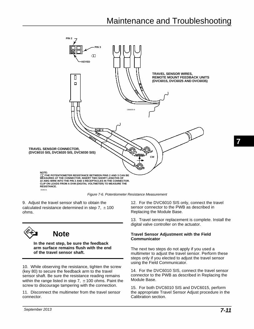
Maintenance and Troubleshooting
September 2013 7-11
NOTE: THE POTENTIOMETER RESISTANCE BETWEEN PINS 2 AND 3 CAN BEMEASURED AT THE CONNECTOR. INSERT TWO SHORT LENGTHS OF22 AWG WIRE INTO THE PIN 2 AND 3 RECEPTACLES IN THE CONNECTOR.CLIP ON LEADS FROM A DVM (DIGITAL VOLTMETER) TO MEASURE THERESISTANCE.
PIN 3
KEYED
PIN 2
CW1
3
A6481/IL
1
1
TRAVEL SENSOR WIRES,REMOTE MOUNT FEEDBACK UNITS(DVC6015, DVC6025 AND DVC6035)
19B6835-B
TRAVEL SENSOR CONNECTOR,(DVC6010 SIS, DVC6020 SIS, DVC6030 SIS)
Figure 7-6. Potentiometer Resistance Measurement
9. Adjust the travel sensor shaft to obtain thecalculated resistance determined in step 7, �100ohms.
NoteIn the next step, be sure the feedbackarm surface remains flush with the endof the travel sensor shaft.
10. While observing the resistance, tighten the screw(key 80) to secure the feedback arm to the travelsensor shaft. Be sure the resistance reading remainswithin the range listed in step 7, �100 ohms. Paint thescrew to discourage tampering with the connection.
11. Disconnect the multimeter from the travel sensorconnector.
12. For the DVC6010 SIS only, connect the travelsensor connector to the PWB as described inReplacing the Module Base.
13. Travel sensor replacement is complete. Install thedigital valve controller on the actuator.
Travel Sensor Adjustment with the FieldCommunicator
The next two steps do not apply if you used amultimeter to adjust the travel sensor. Perform thesesteps only if you elected to adjust the travel sensorusing the Field Communicator.
14. For the DVC6010 SIS, connect the travel sensorconnector to the PWB as described in Replacing theModule Base.
15. For both DVC6010 SIS and DVC6015, performthe appropriate Travel Sensor Adjust procedure in theCalibration section.
7
DVC6000 SIS
September 20137-12
DVC6020 SIS Digital Valve Controller andDVC6025 Remote Feedback UnitRefer to figure 8-2 for DVC6020 SIS and 8-7 forDVC6025 key number locations.
1. Insert the travel sensor assembly (key 223) into thehousing. Secure the travel sensor assembly withscrew (key 72).
If assembling a DVC6020 SIS digital valve controller,use step 2a. If assembling a DVC6025 remotefeedback unit, use step 2b.
2. a. Connect the travel sensor connector to the PWBas described in Replacing the Module Base.
b. Connect the three travel sensor wires to theterminals.
NoteFor the DVC6025 feedback unit,connect the potentiometer assembly(key 223) wires to the terminals asfollows:red � terminal 1white � terminal 2 black � terminal 3
3. Loosely assemble the screw (key 80), plain washer(key 163), and nut (key 81) to the arm assembly (key 91), if not already installed.
4. Attach the arm assembly (key 91) to the travelsensor assembly (key 223) shaft.
Two methods are available for adjusting the travelsensor. You can use a multimeter to measure thepotentiometer resistance, or if you have a FieldCommunicator, you can use the procedure in theCalibration section. To use the multimeter, performsteps 5 through 17. To use the Field Communicator,skip to step 18.
Travel Sensor Adjustment with a Multimeter
5. Connect a multimeter set to a resistance range of50,000 ohms. Measure the resistance between pins 1and 3 of the travel sensor connector. Refer to figure7-6 for pin location. The resistance should be between40,000 and 50,000 ohms.
6. Multiply the result in step 5 by 0.142 to get acalculated resistance. The calculated resistanceshould be in the range of 5680 to 7100 ohms.
7. Re-range the multimeter to a resistance of 7000ohms between pins 2 and 3 of the travel sensorconnector. Refer to figure 7-6 for pin location.
8. Hold the arm assembly (key 91) in a fixed positionso that the arm is parallel to the housing back planeand pointing toward the terminal box. Position the armassembly so that the outer surface is flush with theend of the travel sensor shaft.
9. Adjust the travel sensor shaft to obtain thecalculated resistance determined in step 6, �100ohms.
NoteIn the next step, be sure the armassembly outer surface remains flushwith the end of the travel sensor shaft.
10. While observing the resistance, tighten the screw(key 80) to secure the feedback arm to the travelsensor shaft. Be sure the resistance reading remainswithin the range listed in step 6, �100 ohms. Paint thescrew to discourage tampering with the connection.
11. Disconnect the multimeter from the travel sensorconnector.
12. Apply anti-seize (key 64) to the pin portion of thearm assembly (key 91).
13. Position the mounting bracket over the back of thedigital valve controller. Push the feedback armassembly (key 84) toward the housing and engage thepin of the arm assembly into the slot in the feedbackarm.
14. Install the mounting bracket (key 74).
15. Install the bias spring (key 82) as shown infigure 7-7.
16. For the DVC6020 SIS only, connect the travelsensor connector to the PWB as described inReplacing the Module Base.
17. Travel sensor replacement is complete. Install thedigital valve controller on the actuator.
Travel Sensor Adjustment with the FieldCommunicator
The next two steps do not apply if you used amultimeter to adjust the travel sensor. Perform thesesteps only if you elected to adjust the travel sensorusing the Field Communicator.
18. For the DVC6020 SIS only, connect the travelsensor connector to the PWB as described inReplacing the Module Base.
7
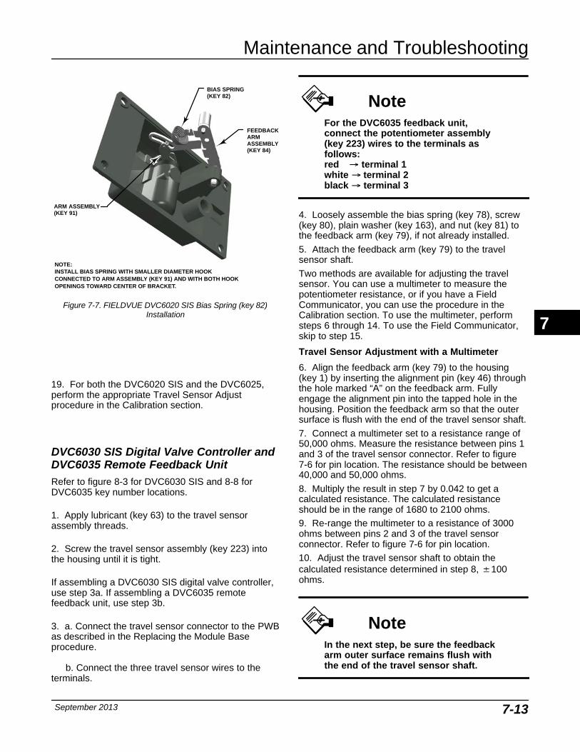
Maintenance and Troubleshooting
September 2013 7-13
Figure 7-7. FIELDVUE DVC6020 SIS Bias Spring (key 82)Installation
BIAS SPRING(KEY 82)
ARM ASSEMBLY(KEY 91)
FEEDBACKARMASSEMBLY(KEY 84)
NOTE:INSTALL BIAS SPRING WITH SMALLER DIAMETER HOOK CONNECTED TO ARM ASSEMBLY (KEY 91) AND WITH BOTH HOOKOPENINGS TOWARD CENTER OF BRACKET.
19. For both the DVC6020 SIS and the DVC6025,perform the appropriate Travel Sensor Adjustprocedure in the Calibration section.
DVC6030 SIS Digital Valve Controller andDVC6035 Remote Feedback UnitRefer to figure 8-3 for DVC6030 SIS and 8-8 forDVC6035 key number locations.
1. Apply lubricant (key 63) to the travel sensorassembly threads.
2. Screw the travel sensor assembly (key 223) intothe housing until it is tight.
If assembling a DVC6030 SIS digital valve controller,use step 3a. If assembling a DVC6035 remotefeedback unit, use step 3b.
3. a. Connect the travel sensor connector to the PWBas described in the Replacing the Module Baseprocedure.
b. Connect the three travel sensor wires to theterminals.
NoteFor the DVC6035 feedback unit,connect the potentiometer assembly(key 223) wires to the terminals asfollows:red � terminal 1white � terminal 2 black � terminal 3
4. Loosely assemble the bias spring (key 78), screw(key 80), plain washer (key 163), and nut (key 81) tothe feedback arm (key 79), if not already installed.
5. Attach the feedback arm (key 79) to the travelsensor shaft.
Two methods are available for adjusting the travelsensor. You can use a multimeter to measure thepotentiometer resistance, or if you have a FieldCommunicator, you can use the procedure in theCalibration section. To use the multimeter, performsteps 6 through 14. To use the Field Communicator,skip to step 15.
Travel Sensor Adjustment with a Multimeter
6. Align the feedback arm (key 79) to the housing(key 1) by inserting the alignment pin (key 46) throughthe hole marked “A” on the feedback arm. Fullyengage the alignment pin into the tapped hole in thehousing. Position the feedback arm so that the outersurface is flush with the end of the travel sensor shaft.
7. Connect a multimeter set to a resistance range of50,000 ohms. Measure the resistance between pins 1and 3 of the travel sensor connector. Refer to figure7-6 for pin location. The resistance should be between40,000 and 50,000 ohms.
8. Multiply the result in step 7 by 0.042 to get acalculated resistance. The calculated resistanceshould be in the range of 1680 to 2100 ohms.9. Re-range the multimeter to a resistance of 3000ohms between pins 2 and 3 of the travel sensorconnector. Refer to figure 7-6 for pin location.10. Adjust the travel sensor shaft to obtain thecalculated resistance determined in step 8, �100ohms.
NoteIn the next step, be sure the feedbackarm outer surface remains flush withthe end of the travel sensor shaft.
7
DVC6000 SIS
September 20137-14
11. While observing the resistance, tighten the screw(key 80) to secure the feedback arm to the travelsensor shaft. Be sure the resistance reading remainswithin the range listed in step 8, �100 ohms. Paint thescrew to discourage tampering with the connection.
12. Disconnect the multimeter from the travel sensorconnector.
13. For the DVC6030 SIS only, connect the travelsensor connector to the PWB as described inReplacing the Module Base.
14. Travel sensor replacement is complete. Install thedigital valve controller on the actuator as described inthe Installation section.
Travel Sensor Adjustment with the FieldCommunicator
The next two steps do not apply if you used amultimeter to adjust the travel sensor. Perform thesesteps only if you elected to adjust the travel sensorusing the Field Communicator.
15. For the DVC6030 SIS only, connect the travelsensor connector to the PWB as described inReplacing the Module Base.
16. For both the DVC6030 SIS and the DVC6035,perform the appropriate Travel Sensor Adjustprocedure in the Calibration section.
Troubleshooting If communication or output difficulties are experiencedwith the instrument, refer to the troubleshooting chartin table 7-3. Also see the DVC6000 SISTroubleshooting Checklist on page 7-18.
Checking Voltage Available
WARNING
Personal injury or property damagecaused by fire or explosion may occurif this test is attempted in an areawhich contains a potentially explosiveatmosphere or has been classified ashazardous.
To check the Voltage Available at the instrument,perform the following:
1. Connect the equipment in figure 2-25 to the fieldwiring in place of the FIELDVUE instrument.
2. Set the control system to provide maximum outputcurrent.
3. Set the resistance of the 1 kilohm potentiometershown in figure 2-25 to zero.
4. Record the current shown on the milliammeter.
5. Adjust the resistance of the 1 kilohm potentiometeruntil the voltage read on the voltmeter is 11.0 volts.
6. Record the current shown on the milliammeter.
7. If the current recorded in step 6 is the same as thatrecorded in step 4 (± 0.08 mA), the voltage available isadequate.
8. If the voltage available is inadequate, refer toWiring Practices in the Installation section.
7
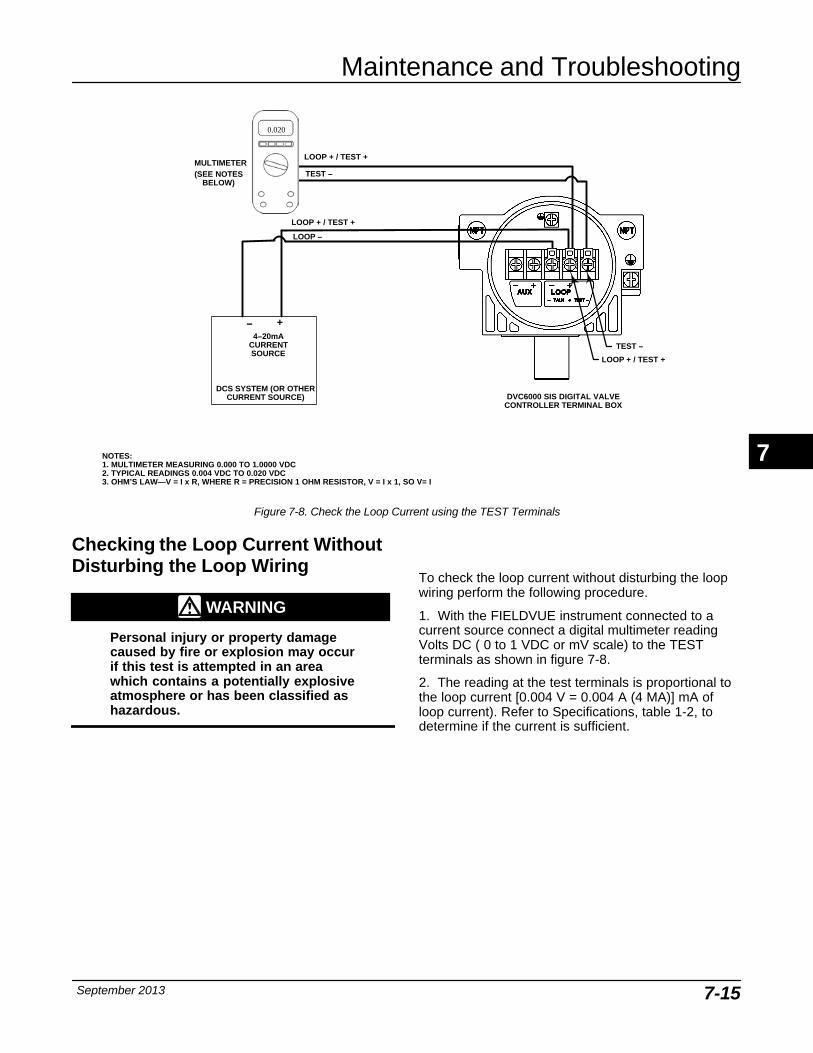
Maintenance and Troubleshooting
September 2013 7-15
LOOP + / TEST +
TEST −
DCS SYSTEM (OR OTHERCURRENT SOURCE)
4−20mACURRENTSOURCE
+−
LOOP −
LOOP + / TEST +
LOOP + / TEST +
TEST −
NOTES:1. MULTIMETER MEASURING 0.000 TO 1.0000 VDC2. TYPICAL READINGS 0.004 VDC TO 0.020 VDC3. OHM’S LAW—V = I x R, WHERE R = PRECISION 1 OHM RESISTOR, V = I x 1, SO V= I
MULTIMETER(SEE NOTES
BELOW)
0.020
DVC6000 SIS DIGITAL VALVECONTROLLER TERMINAL BOX
Figure 7-8. Check the Loop Current using the TEST Terminals
Checking the Loop Current WithoutDisturbing the Loop Wiring
WARNING
Personal injury or property damagecaused by fire or explosion may occurif this test is attempted in an areawhich contains a potentially explosiveatmosphere or has been classified ashazardous.
To check the loop current without disturbing the loopwiring perform the following procedure.
1. With the FIELDVUE instrument connected to acurrent source connect a digital multimeter readingVolts DC ( 0 to 1 VDC or mV scale) to the TESTterminals as shown in figure 7-8.
2. The reading at the test terminals is proportional tothe loop current [0.004 V = 0.004 A (4 MA)] mA ofloop current). Refer to Specifications, table 1-2, todetermine if the current is sufficient.
7
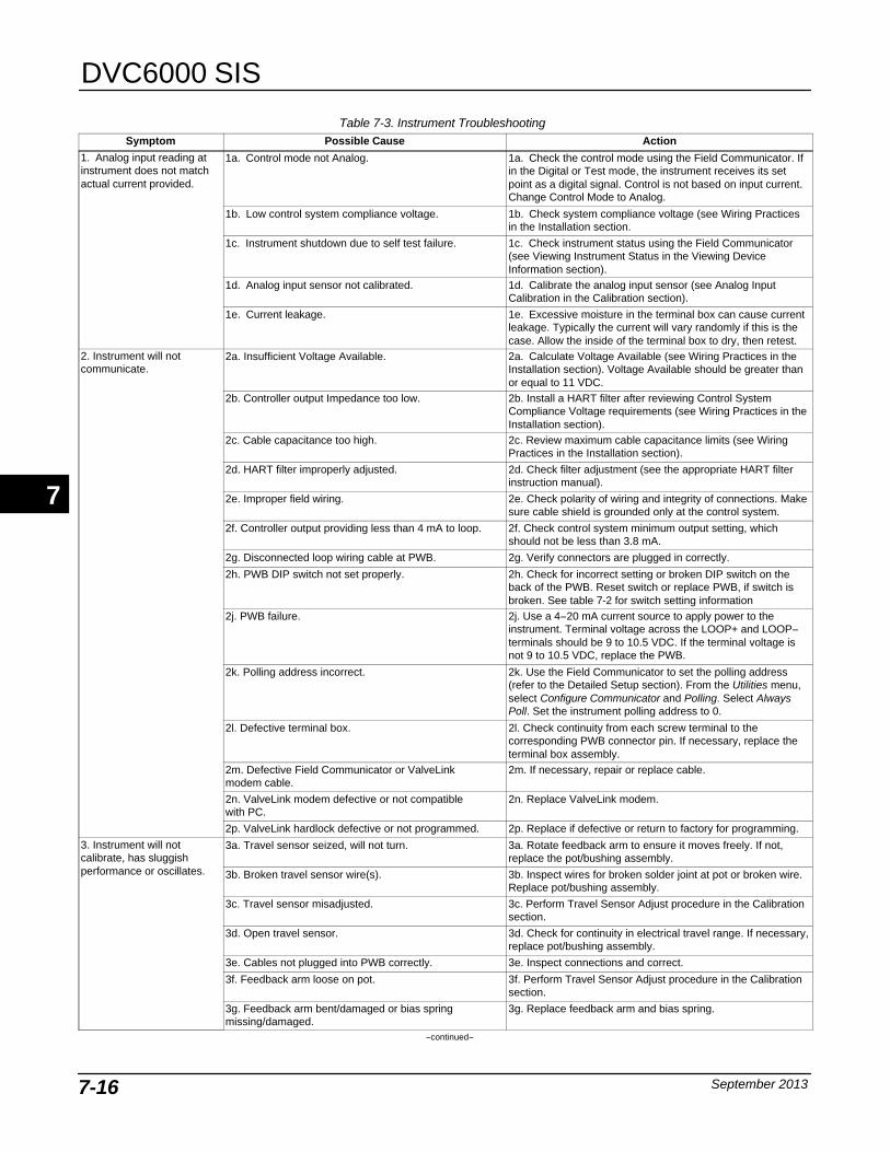
DVC6000 SIS
September 20137-16
Table 7-3. Instrument Troubleshooting Symptom Possible Cause Action
1. Analog input reading atinstrument does not matchactual current provided.
1a. Control mode not Analog. 1a. Check the control mode using the Field Communicator. Ifin the Digital or Test mode, the instrument receives its setpoint as a digital signal. Control is not based on input current.Change Control Mode to Analog.
1b. Low control system compliance voltage. 1b. Check system compliance voltage (see Wiring Practicesin the Installation section.
1c. Instrument shutdown due to self test failure. 1c. Check instrument status using the Field Communicator(see Viewing Instrument Status in the Viewing DeviceInformation section).
1d. Analog input sensor not calibrated. 1d. Calibrate the analog input sensor (see Analog InputCalibration in the Calibration section).
1e. Current leakage. 1e. Excessive moisture in the terminal box can cause currentleakage. Typically the current will vary randomly if this is thecase. Allow the inside of the terminal box to dry, then retest.
2. Instrument will notcommunicate.
2a. Insufficient Voltage Available. 2a. Calculate Voltage Available (see Wiring Practices in theInstallation section). Voltage Available should be greater thanor equal to 11 VDC.
2b. Controller output Impedance too low. 2b. Install a HART filter after reviewing Control SystemCompliance Voltage requirements (see Wiring Practices in theInstallation section).
2c. Cable capacitance too high. 2c. Review maximum cable capacitance limits (see WiringPractices in the Installation section).
2d. HART filter improperly adjusted. 2d. Check filter adjustment (see the appropriate HART filterinstruction manual).
2e. Improper field wiring. 2e. Check polarity of wiring and integrity of connections. Makesure cable shield is grounded only at the control system.
2f. Controller output providing less than 4 mA to loop. 2f. Check control system minimum output setting, whichshould not be less than 3.8 mA.
2g. Disconnected loop wiring cable at PWB. 2g. Verify connectors are plugged in correctly.
2h. PWB DIP switch not set properly. 2h. Check for incorrect setting or broken DIP switch on theback of the PWB. Reset switch or replace PWB, if switch isbroken. See table 7-2 for switch setting information
2j. PWB failure. 2j. Use a 4−20 mA current source to apply power to theinstrument. Terminal voltage across the LOOP+ and LOOP−terminals should be 9 to 10.5 VDC. If the terminal voltage isnot 9 to 10.5 VDC, replace the PWB.
2k. Polling address incorrect. 2k. Use the Field Communicator to set the polling address(refer to the Detailed Setup section). From the Utilities menu,select Configure Communicator and Polling. Select AlwaysPoll. Set the instrument polling address to 0.
2l. Defective terminal box. 2l. Check continuity from each screw terminal to thecorresponding PWB connector pin. If necessary, replace theterminal box assembly.
2m. Defective Field Communicator or ValveLinkmodem cable.
2m. If necessary, repair or replace cable.
2n. ValveLink modem defective or not compatiblewith PC.
2n. Replace ValveLink modem.
2p. ValveLink hardlock defective or not programmed. 2p. Replace if defective or return to factory for programming.
3. Instrument will notcalibrate, has sluggishperformance or oscillates.
3a. Travel sensor seized, will not turn. 3a. Rotate feedback arm to ensure it moves freely. If not,replace the pot/bushing assembly.
3b. Broken travel sensor wire(s). 3b. Inspect wires for broken solder joint at pot or broken wire.Replace pot/bushing assembly.
3c. Travel sensor misadjusted. 3c. Perform Travel Sensor Adjust procedure in the Calibrationsection.
3d. Open travel sensor. 3d. Check for continuity in electrical travel range. If necessary,replace pot/bushing assembly.
3e. Cables not plugged into PWB correctly. 3e. Inspect connections and correct.
3f. Feedback arm loose on pot. 3f. Perform Travel Sensor Adjust procedure in the Calibrationsection.
3g. Feedback arm bent/damaged or bias springmissing/damaged.
3g. Replace feedback arm and bias spring.
−continued−
7
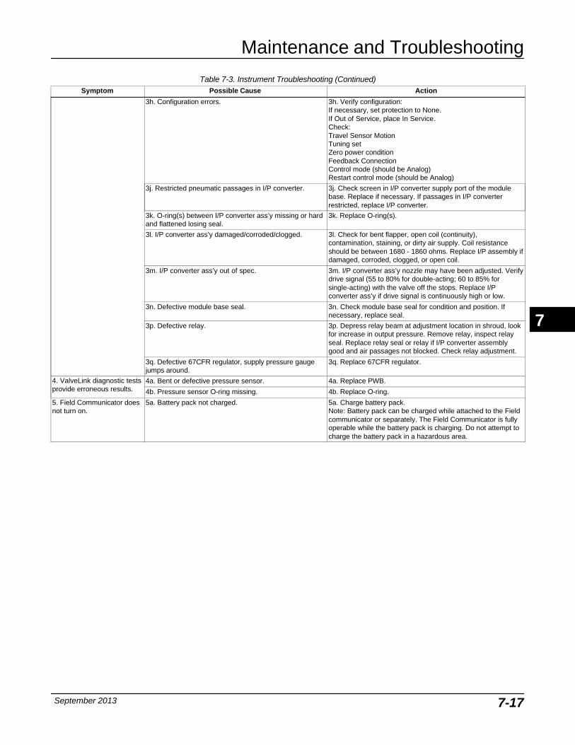
Maintenance and Troubleshooting
September 2013 7-17
Table 7-3. Instrument Troubleshooting (Continued)Symptom ActionPossible Cause
3h. Configuration errors. 3h. Verify configuration:If necessary, set protection to None.If Out of Service, place In Service.Check:Travel Sensor MotionTuning setZero power conditionFeedback ConnectionControl mode (should be Analog)Restart control mode (should be Analog)
3j. Restricted pneumatic passages in I/P converter. 3j. Check screen in I/P converter supply port of the modulebase. Replace if necessary. If passages in I/P converterrestricted, replace I/P converter.
3k. O-ring(s) between I/P converter ass’y missing or hardand flattened losing seal.
3k. Replace O-ring(s).
3l. I/P converter ass’y damaged/corroded/clogged. 3l. Check for bent flapper, open coil (continuity),contamination, staining, or dirty air supply. Coil resistanceshould be between 1680 - 1860 ohms. Replace I/P assembly ifdamaged, corroded, clogged, or open coil.
3m. I/P converter ass’y out of spec. 3m. I/P converter ass’y nozzle may have been adjusted. Verifydrive signal (55 to 80% for double-acting; 60 to 85% forsingle-acting) with the valve off the stops. Replace I/Pconverter ass’y if drive signal is continuously high or low.
3n. Defective module base seal. 3n. Check module base seal for condition and position. Ifnecessary, replace seal.
3p. Defective relay. 3p. Depress relay beam at adjustment location in shroud, lookfor increase in output pressure. Remove relay, inspect relayseal. Replace relay seal or relay if I/P converter assemblygood and air passages not blocked. Check relay adjustment.
3q. Defective 67CFR regulator, supply pressure gaugejumps around.
3q. Replace 67CFR regulator.
4. ValveLink diagnostic testsprovide erroneous results.
4a. Bent or defective pressure sensor. 4a. Replace PWB.
4b. Pressure sensor O-ring missing. 4b. Replace O-ring.
5. Field Communicator doesnot turn on.
5a. Battery pack not charged. 5a. Charge battery pack. Note: Battery pack can be charged while attached to the Fieldcommunicator or separately. The Field Communicator is fullyoperable while the battery pack is charging. Do not attempt tocharge the battery pack in a hazardous area.
7
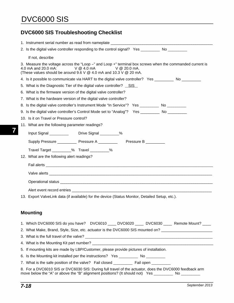
DVC6000 SIS
September 20137-18
DVC6000 SIS Troubleshooting Checklist
1. Instrument serial number as read from nameplate ________________________________________________
2. Is the digital valve controller responding to the control signal? Yes _________ No _________
If not, describe
3. Measure the voltage across the “Loop −” and Loop +” terminal box screws when the commanded current is4.0 mA and 20.0 mA: V @ 4.0 mA V @ 20.0 mA.(These values should be around 9.6 V @ 4.0 mA and 10.3 V @ 20 mA.
4. Is it possible to communicate via HART to the digital valve controller? Yes _________ No _________
5. What is the Diagnostic Tier of the digital valve controller? SIS
6. What is the firmware version of the digital valve controller?
7. What is the hardware version of the digital valve controller?
8. Is the digital valve controller’s Instrument Mode “In Service”? Yes _________ No _________
9. Is the digital valve controller’s Control Mode set to “Analog”? Yes _________ No _________
10. Is it on Travel or Pressure control?
11. What are the following parameter readings?
Input Signal _________ Drive Signal _________%
Supply Pressure _________ Pressure A _________ Pressure B _________
Travel Target _________% Travel _________%
12. What are the following alert readings?
Fail alerts _______________________________________________________________________________
Valve alerts _____________________________________________________________________________
Operational status ________________________________________________________________________
Alert event record entries __________________________________________________________________
13. Export ValveLink data (if available) for the device (Status Monitor, Detailed Setup, etc.).
Mounting
1. Which DVC6000 SIS do you have? DVC6010 ____ DVC6020 ____ DVC6030 ____ Remote Mount? ____
2. What Make, Brand, Style, Size, etc. actuator is the DVC6000 SIS mounted on? ________________________
3. What is the full travel of the valve? ____________________________________________________________
4. What is the Mounting Kit part number? _________________________________________________________
5. If mounting kits are made by LBP/Customer, please provide pictures of installation.
6. Is the Mounting kit installed per the instructions? Yes _________ No _________
7. What is the safe position of the valve? Fail closed _________ Fail open _________
8. For a DVC6010 SIS or DVC6030 SIS: During full travel of the actuator, does the DVC6000 feedback armmove below the “A” or above the “B” alignment positions? (It should not) Yes _________ No _________
7
Parts
September 2013 8-1
8-8
Section 8 Parts
Parts Ordering 8-2. . . . . . . . . . . . . . . . . . . . . . . . . . . . . . . . . . . . . . . . . . . . . . . . . . . . . . . . . . .
Parts Kits 8-2. . . . . . . . . . . . . . . . . . . . . . . . . . . . . . . . . . . . . . . . . . . . . . . . . . . . . . . . . . . . . . . .
Parts List 8-4. . . . . . . . . . . . . . . . . . . . . . . . . . . . . . . . . . . . . . . . . . . . . . . . . . . . . . . . . . . . . . . .
Housing 8-4. . . . . . . . . . . . . . . . . . . . . . . . . . . . . . . . . . . . . . . . . . . . . . . . . . . . . . . . . . . . . . . . .
Common Parts 8-4. . . . . . . . . . . . . . . . . . . . . . . . . . . . . . . . . . . . . . . . . . . . . . . . . . . . . . . . . .
Module Base 8-4. . . . . . . . . . . . . . . . . . . . . . . . . . . . . . . . . . . . . . . . . . . . . . . . . . . . . . . . . . . .
I/P Assembly 8-4. . . . . . . . . . . . . . . . . . . . . . . . . . . . . . . . . . . . . . . . . . . . . . . . . . . . . . . . . . . .
Relay 8-4. . . . . . . . . . . . . . . . . . . . . . . . . . . . . . . . . . . . . . . . . . . . . . . . . . . . . . . . . . . . . . . . . . . .
Terminal Box 8-5. . . . . . . . . . . . . . . . . . . . . . . . . . . . . . . . . . . . . . . . . . . . . . . . . . . . . . . . . . . .
PWB Assembly 8-5. . . . . . . . . . . . . . . . . . . . . . . . . . . . . . . . . . . . . . . . . . . . . . . . . . . . . . . . . .
Pressure Gauges, Pipe Plugs, or Tire Valve Assemblies 8-5. . . . . . . . . . . . . . . . . . .
Feedback / Remote Travel Parts 8-5. . . . . . . . . . . . . . . . . . . . . . . . . . . . . . . . . . . . . . . . .
LC340 Line Conditioner 8-6. . . . . . . . . . . . . . . . . . . . . . . . . . . . . . . . . . . . . . . . . . . . . . . . . .
8
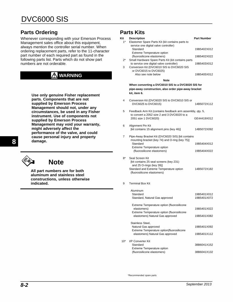
DVC6000 SIS
September 20138-2
Parts Ordering Whenever corresponding with your Emerson ProcessManagement sales office about this equipment,always mention the controller serial number. Whenordering replacement parts, refer to the 11-characterpart number of each required part as found in thefollowing parts list. Parts which do not show partnumbers are not orderable.
WARNING
Use only genuine Fisher replacementparts. Components that are notsupplied by Emerson ProcessManagement should not, under anycircumstances, be used in any Fisherinstrument. Use of components notsupplied by Emerson ProcessManagement may void your warranty,might adversely affect theperformance of the valve, and couldcause personal injury and propertydamage.
NoteAll part numbers are for bothaluminum and stainless steelconstructions, unless otherwiseindicated.
Parts Kits Kit Description Part Number
1* Elastomer Spare Parts Kit (kit contains parts toservice one digital valve controller)Standard 19B5402X012Extreme Temperature option(fluorosilicone elastomers) 19B5402X022
2* Small Hardware Spare Parts Kit (kit contains partsto service one digital valve controller) 19B5403X012
3 Conversion Kit (DVC6010 SIS to DVC6020 SISor DVC6015 to DVC6025)
Also see note below 19B5405X012
Note
When converting a DVC6010 SIS to a DVC6020 SIS forpipe-away construction, also order pipe-away bracketkit, item 6.
4 Conversion Kit (DVC6020 SIS to DVC6010 SIS or DVC6025 to DVC6015) 14B5072X112
5 Feedback Arm Kit (contains feedback arm assembly, qty. 5,to convert a 2052 size 2 and 3 DVC6020 to a 2051 size 1 DVC6020) GE44419X012
6 Alignment Pin Kit [kit contains 15 alignment pins (key 46)] 14B5072X092
7 Pipe-Away Bracket Kit (DVC6020 SIS) [kit containsmounting bracket (key 74) and O-ring (key 75)]Standard 19B5404X012Extreme Temperature option(fluorosilicone elastomers) 19B5404X022
8* Seal Screen Kit [kit contains 25 seal screens (key 231)and 25 O-rings (key 39)]
Standard and Extreme Temperature option 14B5072X182(fluorosilicone elastomers)
9 Terminal Box Kit
AluminumStandard 19B5401X012Standard, Natural Gas approved 19B5401X072
Extreme Temperature option (fluorosiliconeelastomers) 19B5401X022
Extreme Temperature option (fluorosiliconeelastomers) Natural Gas approved 19B5401X082
Stainless Steel,Natural Gas approved 19B5401X092Extreme Temperature option(fluorosiliconeelastomers) Natural Gas approved 19B5401X112
10* I/P Converter KitStandard 38B6041X152Extreme Temperature option(fluorosilicone elastomers) 38B6041X132
8
*Recommended spare parts
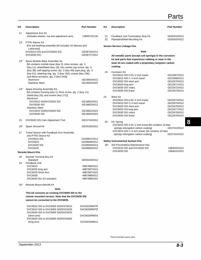
Parts
September 2013 8-3
Kit Description Part Number
11 Adjustment Arm Kit(includes washer, nut and adjustment arm) 14B5072X132
12* PTFE Sleeve Kit[For pot bushing assembly (kit includes 10 sleeves andLubricant)]
DVC6010 SIS and DVC6020 SIS GE08726X012DVC6030 SIS GE08727X012
13* Spare Module Base Assembly Kit,[kit contains module base (key 2); drive screws, qty. 2,(key 11); shield/label (key 19); hex socket cap screw, qty. 3, (key 38); self tapping screw, qty. 2 (key 49); pipe plug, qty. 3 (key 61); retaining ring, qty. 3 (key 154); screen (key 236); and flame arrestors, qty. 3 (key 243)]Aluminum GE18654X012Stainless Steel GE18654X022
14* Spare Housing Assembly Kit, [kit contains housing (key 1); drive screw, qty. 2 (key 11); shield (key 20); and screen (key 271)]Aluminum
DVC6010 SIS/DVC6020 SIS GE18652X012DVC6030 SIS GE18653X012
Stainless SteelDVC6010 SIS/DVC6020 SIS GE18652X022DVC6030 SIS GE18653X022
15 DVC6020 SIS Cam Adjustment Tool GE12742X012
16* Spare Shroud Kit GE29183X012
17 Travel Sensor with Feedback Arm Assemblyand PTFE Sleeve KitDVC6010 SIS GG09947X012DVC6015 GG09948X012DVC6020 SIS GG09949X012DVC6025 GG09950X012
Remote Mount Kits
18 Remote Terminal Box KitStandard GE00418X012
19 Feedback UnitDVC6015 49B7986X012DVC6025 long arm 49B7987X012DVC6025 Short Arm 49B7987X022DVC6035 49B7988X012DVC6035 (for GX actuator) 49B7988X022
20* Remote Mount Retrofit Kit
Note
This kit converts an existing DVC6000 SIS to theremote mounted version. Note that the DVC6030 SIScannot be converted to the DVC6035.
DVC6010 SIS to DVC6005 SIS/DVC6015 DVC6015RMTRDVC6010 SIS to DVC6005 SIS/DVC6035 DVC6035RMTRDVC6020 SIS to DVC6005 SIS/DVC6025(short arm) DVC6025RMSA
DVC6020 SIS to DVC6005 SIS/DVC6025(long arm) DVC6025RMLA
Kit Description Part Number
21 Feedback Unit Termination Strip Kit GE00419X01222 Pipestand/Wall Mounting Kit GE00420X012
Severe Service Linkage Kits
Note
All metallic parts (except coil springs) in the corrosionkit and parts that experience rubbing or wear in thewear kit are coated with a proprietary tungsten carboncoating.
23 Corrosion KitDVC6010 SIS 0.25−2 Inch travel GE22667X012DVC6010 SIS 2−4 Inch travel GE22668X012DVC6020 SIS short arm GE22670X012DVC6020 long arm GE22671X012DVC6030 SIS rotary GE22672X012DVC6030 SIS linear GE22673X012
24 Wear KitDVC6010 SIS 0.25−2 Inch travel GE22674X012DVC6010 SIS 2−4 Inch travel GE22675X012DVC6020 SIS short arm GE22676X012DVC6020 SIS long arm GE22677X012DVC6030 SIS rotary GE22678X012DVC6030 SIS linear GE22679X012
25 Kit, SpringDVC6010 SIS 0.25−2 inch travel [kit contains 10 biassprings w/tungsten carbon coating] GE37413X012
DVC6010 SIS 2−4 inch travel, [kit contains 10 biassprings w/tungsten carbon coating] GE37414X012
Safety Instrumented System Kits
26* SIS Preventative Maintenance KitsDVC6010 SIS and DVC6020 SIS 19B4032X012DVC6030 SIS 19B4031X012
8
*Recommended spare parts
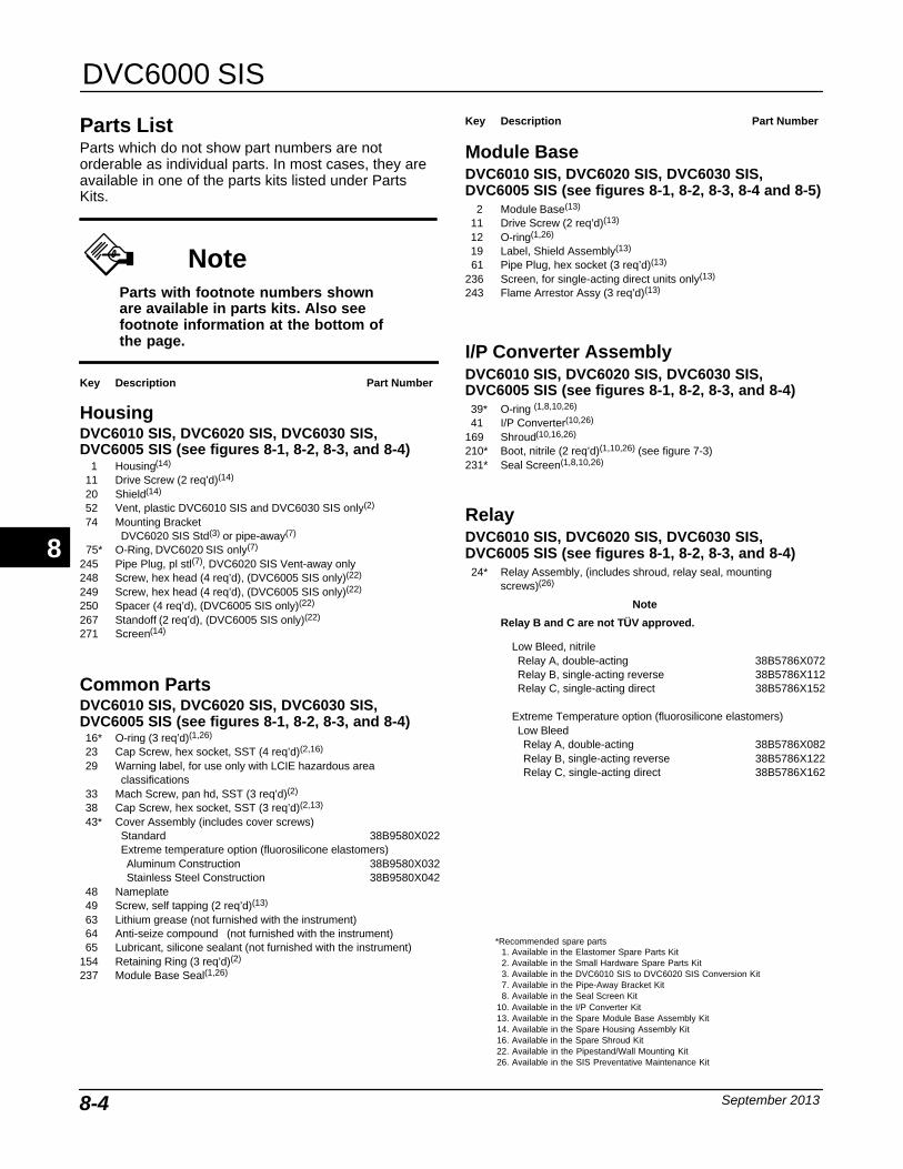
DVC6000 SIS
September 20138-4
Parts ListParts which do not show part numbers are notorderable as individual parts. In most cases, they areavailable in one of the parts kits listed under PartsKits.
NoteParts with footnote numbers shownare available in parts kits. Also seefootnote information at the bottom ofthe page.
Key Description Part Number
HousingDVC6010 SIS, DVC6020 SIS, DVC6030 SIS,DVC6005 SIS (see figures 8-1, 8-2, 8-3, and 8-4)
1 Housing(14)
11 Drive Screw (2 req’d)(14)
20 Shield(14)
52 Vent, plastic DVC6010 SIS and DVC6030 SIS only(2)
74 Mounting BracketDVC6020 SIS Std(3) or pipe-away(7)
75* O-Ring, DVC6020 SIS only(7)
245 Pipe Plug, pl stl(7), DVC6020 SIS Vent-away only248 Screw, hex head (4 req’d), (DVC6005 SIS only)(22)
249 Screw, hex head (4 req’d), (DVC6005 SIS only)(22)
250 Spacer (4 req’d), (DVC6005 SIS only)(22)
267 Standoff (2 req’d), (DVC6005 SIS only)(22)
271 Screen(14)
Common PartsDVC6010 SIS, DVC6020 SIS, DVC6030 SIS,DVC6005 SIS (see figures 8-1, 8-2, 8-3, and 8-4)16* O-ring (3 req’d)(1,26)
23 Cap Screw, hex socket, SST (4 req’d)(2,16)
29 Warning label, for use only with LCIE hazardous areaclassifications
33 Mach Screw, pan hd, SST (3 req’d)(2)
38 Cap Screw, hex socket, SST (3 req’d)(2,13)
43* Cover Assembly (includes cover screws)Standard 38B9580X022Extreme temperature option (fluorosilicone elastomers)Aluminum Construction 38B9580X032Stainless Steel Construction 38B9580X042
48 Nameplate49 Screw, self tapping (2 req’d)(13)
63 Lithium grease (not furnished with the instrument)64 Anti-seize compound (not furnished with the instrument)65 Lubricant, silicone sealant (not furnished with the instrument)
154 Retaining Ring (3 req’d)(2)
237 Module Base Seal(1,26)
Key Description Part Number
Module Base DVC6010 SIS, DVC6020 SIS, DVC6030 SIS,DVC6005 SIS (see figures 8-1, 8-2, 8-3, 8-4 and 8-5)
2 Module Base(13)
11 Drive Screw (2 req’d)(13)
12 O-ring(1,26)
19 Label, Shield Assembly(13)
61 Pipe Plug, hex socket (3 req’d)(13)
236 Screen, for single-acting direct units only(13)
243 Flame Arrestor Assy (3 req’d)(13)
I/P Converter AssemblyDVC6010 SIS, DVC6020 SIS, DVC6030 SIS,DVC6005 SIS (see figures 8-1, 8-2, 8-3, and 8-4)39* O-ring (1,8,10,26)
41 I/P Converter(10,26)
169 Shroud(10,16,26)
210* Boot, nitrile (2 req’d)(1,10,26) (see figure 7-3)231* Seal Screen(1,8,10,26)
Relay DVC6010 SIS, DVC6020 SIS, DVC6030 SIS,DVC6005 SIS (see figures 8-1, 8-2, 8-3, and 8-4)24* Relay Assembly, (includes shroud, relay seal, mounting
screws)(26)
Note
Relay B and C are not TÜV approved.
Low Bleed, nitrileRelay A, double-acting 38B5786X072Relay B, single-acting reverse 38B5786X112Relay C, single-acting direct 38B5786X152
Extreme Temperature option (fluorosilicone elastomers)Low BleedRelay A, double-acting 38B5786X082Relay B, single-acting reverse 38B5786X122Relay C, single-acting direct 38B5786X162
8
*Recommended spare parts1. Available in the Elastomer Spare Parts Kit2. Available in the Small Hardware Spare Parts Kit3. Available in the DVC6010 SIS to DVC6020 SIS Conversion Kit7. Available in the Pipe-Away Bracket Kit8. Available in the Seal Screen Kit
10. Available in the I/P Converter Kit13. Available in the Spare Module Base Assembly Kit14. Available in the Spare Housing Assembly Kit16. Available in the Spare Shroud Kit22. Available in the Pipestand/Wall Mounting Kit26. Available in the SIS Preventative Maintenance Kit
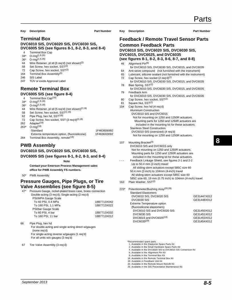
Parts
September 2013 8-5
Key Description Part Number
Terminal Box DVC6010 SIS, DVC6020 SIS, DVC6030 SIS,DVC6005 SIS (see figures 8-1, 8-2, 8-3, and 8-4)
4 Terminal Box Cap34* O-ring(1,9,26)
36* O-ring(1,9,26)
44 Wire Retainer, pl stl (6 req’d) (not shown)(2)
58 Set Screw, hex socket, SST(2)
72 Cap Screw, hex socket, SST(2)
164 Terminal Box Assembly(9)
246 SIS Label247 TÜV or exida Approval Label
Remote Terminal BoxDVC6005 SIS (see figure 8-4)
4 Terminal Box Cap(18)
34* O-ring(1,9,18)
36* O-ring(1,9,18)
44 Wire Retainer, pl stl (5 req’d) (not shown)(2,19)
58 Set Screw, hex socket, SST(2,18)
62 Pipe Plug, hex hd, SST(18)
72 Cap Screw, hex socket, SST (3 req’d)(2,18)
262 Adapter(18)
263* O-ring(18)
Standard 1F463606992Extreme temperature option, (fluorosilicone) 1F4636X0092
264 Terminal Box Assembly, remote(18)
PWB AssemblyDVC6010 SIS, DVC6020 SIS, DVC6030 SIS,DVC6005 SIS (see figures 8-1, 8-2, 8-3, and 8-4)
Note
Contact your Emerson Process Management salesoffice for PWB Assembly FS numbers.
50* PWB Assembly
Pressure Gauges, Pipe Plugs, or TireValve Assemblies (see figure 8-5)47* Pressure Gauge, nickel-plated brass case, brass connection
Double-acting (3 req’d); Single-acting (2 req’d)PSI/MPA Gauge ScaleTo 60 PSI, 0.4 MPa 18B7713X042To 160 PSI, 1.1 MPa 18B7713X022
PSI/bar Gauge ScaleTo 60 PSI, 4 bar 18B7713X032To 160 PSI, 11 bar 18B7713X012
66 Pipe Plug, hex hdFor double-acting and single acting direct w/gauges(none req’d)
For single-acting reverse w/gauges (1 req’d)For all units w/o gauges (3 req’d)
67 Tire Valve Assembly (3 req’d)
Key Description Part Number
Feedback / Remote Travel Sensor PartsCommon Feedback PartsDVC6010 SIS, DVC6020 SIS, DVC6030 SIS,DVC6015, DVC6025, and DVC6035(see figures 8-1, 8-2, 8-3, 8-6, 8-7, and 8-8)46 Alignment Pin(6)
for DVC6010 SIS, DVC6030 SIS, DVC6015, and DVC603564 Anti-seize compound (not furnished with the instrument)65 Lubricant, silicone sealant (not furnished with the instrument)72 Cap Screw, hex socket (2 req’d)(2)
for DVC6010 SIS, DVC6030 SIS, DVC6015, and DVC603578 Bias Spring, SST(2)
for DVC6010 SIS, DVC6030 SIS, DVC6015, and DVC603579 Feedback Arm
for DVC6010 SIS, DVC6030 SIS, DVC6015, and DVC603580 Cap Screw, hex socket, SST(2)
81 Square Nut, SST(2)
104 Cap Screw, hex hd (4 req’d) Aluminum ConstructionDVC6010 SIS and DVC6015Not for mounting on 1250 and 1250R actuators.Mounting parts for 1250 and 1250R actuators areincluded in the mounting kit for these actuators.
Stainless Steel ConstructionDVC6010 SIS (oversized) (4 req’d)Not for mounting on 1250 and 1250R actuators.
107 Mounting Bracket(4)
DVC6010 SIS and DVC6015 onlyNot for mounting on 1250 and 1250R actuators.Mounting parts for 1250 and 1250R actuators areincluded in the mounting kit for these actuators.
- - - Feedback Linkage Shield, see figures 2-1 and 2-2Up to 50.4 mm (2-inch) travelAll sliding-stem actuators except 585C size 60
50.4 mm (2-inch) to 104mm (4-inch) travelAll sliding-stem actuators except 585C size 60
585C size 60, 19 mm (0.75 inch) to 104mm (4-inch) travel163 Plain Washer, SST(2)
223* Potentiometer/Bushing Assy(20,26)
Standard ElastomersDVC6010 SIS, DVC6020 SIS GE31447X012DVC6030 SIS GE31448X012
Extreme Temperature option (fluorosilicone elastomers)DVC6010 SIS and DVC6020 SIS GE31450X012DVC6030 SIS GE31451X012DVC6015 and DVC6025(19) GE31453X012DVC6035(19) GE31454X012
8
*Recommended spare parts1. Available in the Elastomer Spare Parts Kit2. Available in the Small Hardware Spare Parts Kit4. Available in the DVC6020 SIS to DVC6010 SIS Conversion Kit6. Available in the Alignment Pin Kit9. Available in the Terminal Box Kit
18. Available in the Remote Terminal Box Kit19. Available in Feedback Unit Kit20. Available in the Remote Mount Retrofit Kit26. Available in the SIS Preventative Maintenance Kit

DVC6000 SIS
September 20138-6
Key Description Part Number
DVC6020 SIS and DVC6025 (see figure 8-2 and 8-7)74 Mounting Bracket82 Bias Spring, SST(3)
83 Bearing Flange, PTFE-based (2 req’d)(3)
84 Feedback Arm Assy, SST(3)
85 E-ring, pl stl (2 req’d)(3)
86 Plain Washer, pl stl (2 req’d)(3)
87 Follower Post, SST(3)
88 Roller, SST/PTFE(3)
89 Spring Lock Washer, pl stl(3)
90 Hex Nut, pl stl(3)
91 Arm Assy, SST92 Cap Screw, hex socket (4 req’d)(3)
93 Torsion Spring, Feedback Arm(3)
DVC6015, DVC6025, and DVC6035(see figures 8-6, 8-7, and 8-8)23 Cap Screw, hex socket (2 req’d)(19,21)
44 Wire Retainer, pl stl (9 req’d)(19,21)
49 Screw, self tapping (2 req’d)
Key Description Part Number
58 Set Screw, hex socket(19)
62 Pipe Plug, hex hd, SST(19)
131 Retainer Wire251 Feedback housing(19)
252 Assembly Plate Shield (DVC6015 only)(19)
253 Terminal bracket(19,21)
254 Terminal Strip(19,21)
255 Terminal Cap(19)
256 O-ring, fluorosilicone(19)
257 Machine Screw, pan head (2 req’d) (DVC6015 only)(19)
258 Label, cover(19)
260 Hex Nut, SST (2 req’d)261 Nameplate265 Plug (DVC6015 and DVC6035 only)(19)
Line ConditionerLC340 Line conditioner 39B5416X012
8
*Recommended spare parts3. Available in the DVC6010 SIS to DVC6020 SIS Conversion Kit
19. Available in Feedback Unit Kit21. Available in Feedback Unit Termination Strip Kit
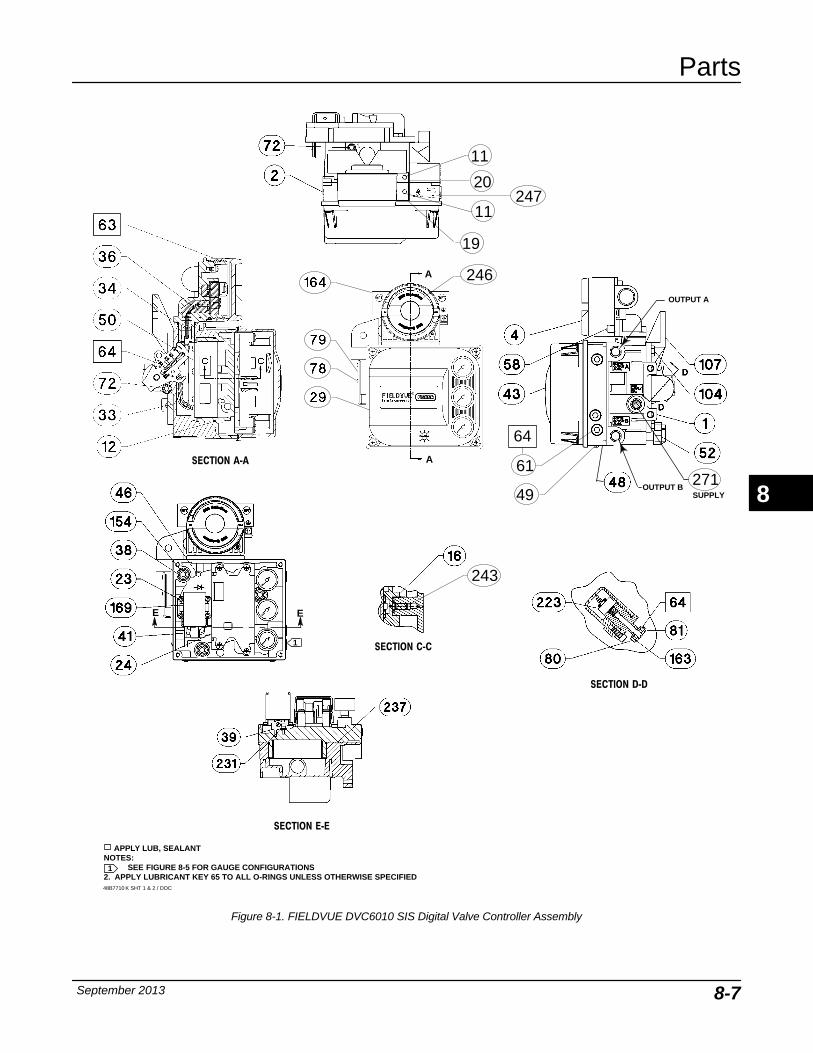
Parts
September 2013 8-7
Figure 8-1. FIELDVUE DVC6010 SIS Digital Valve Controller Assembly
APPLY LUB, SEALANT
SECTION A‐A
SECTION E‐E
E E
SECTION D‐D
1
1
NOTES:SEE FIGURE 8-5 FOR GAUGE CONFIGURATIONS
2. APPLY LUBRICANT KEY 65 TO ALL O-RINGS UNLESS OTHERWISE SPECIFIED
OUTPUT A
OUTPUT BSUPPLY
SECTION C‐C
A
A
48B7710 K SHT 1 & 2 / DOC
11
11
19
20
27161
49
64
243
246
247
8
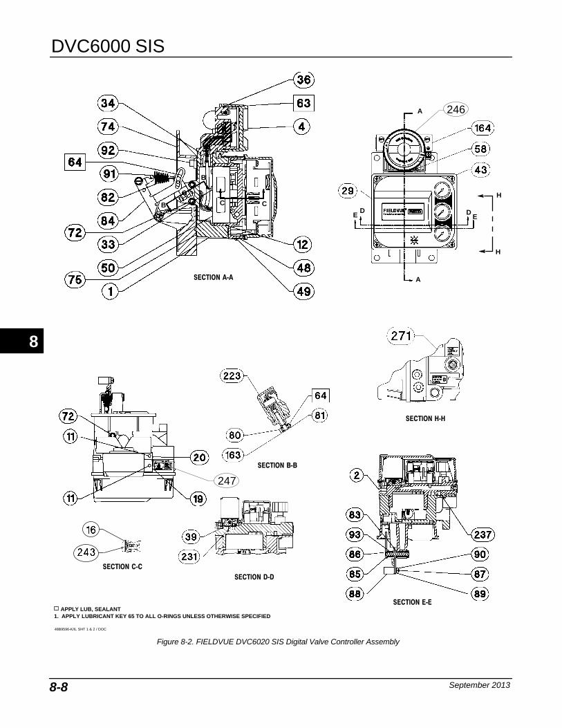
DVC6000 SIS
September 20138-8
Figure 8-2. FIELDVUE DVC6020 SIS Digital Valve Controller Assembly
APPLY LUB, SEALANT
SECTION B‐B
SECTION C‐C
SECTION A‐A
SECTION D‐D
SECTION E‐E
A
A
DDE E
C C
B
B
48B9596-K/IL SHT 1 & 2 / DOC
H
H
SECTION H‐H
1. APPLY LUBRICANT KEY 65 TO ALL O-RINGS UNLESS OTHERWISE SPECIFIED
246
247
8
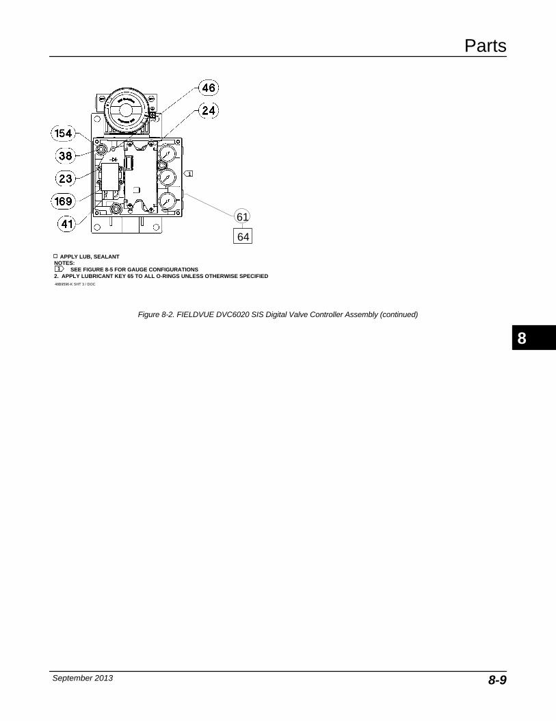
Parts
September 2013 8-9
Figure 8-2. FIELDVUE DVC6020 SIS Digital Valve Controller Assembly (continued)
APPLY LUB, SEALANTNOTES:
SEE FIGURE 8-5 FOR GAUGE CONFIGURATIONS2. APPLY LUBRICANT KEY 65 TO ALL O-RINGS UNLESS OTHERWISE SPECIFIED
1
1
48B9596-K SHT 3 / DOC
61
64
8
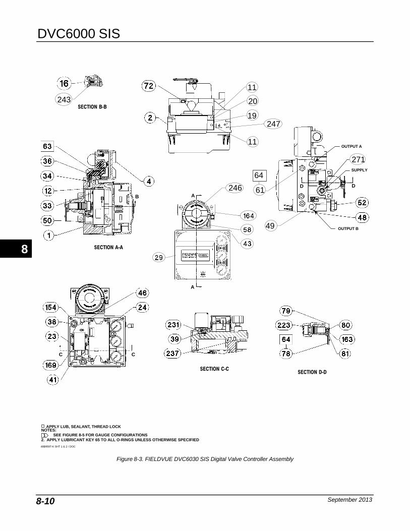
DVC6000 SIS
September 20138-10
NOTES:SEE FIGURE 8-5 FOR GAUGE CONFIGURATIONS
2. APPLY LUBRICANT KEY 65 TO ALL O-RINGS UNLESS OTHERWISE SPECIFIED
Figure 8-3. FIELDVUE DVC6030 SIS Digital Valve Controller Assembly
SECTION C‐C
APPLY LUB, SEALANT, THREAD LOCK
SECTION A‐A
SECTION D‐D
SECTION B‐B
1
1
OUTPUT A
SUPPLY
OUTPUT B
48B9597-K SHT 1 & 2 / DOC
A
A
C C
B B
D D
11
11
19
20
61
49
64
271
243
246
247
8
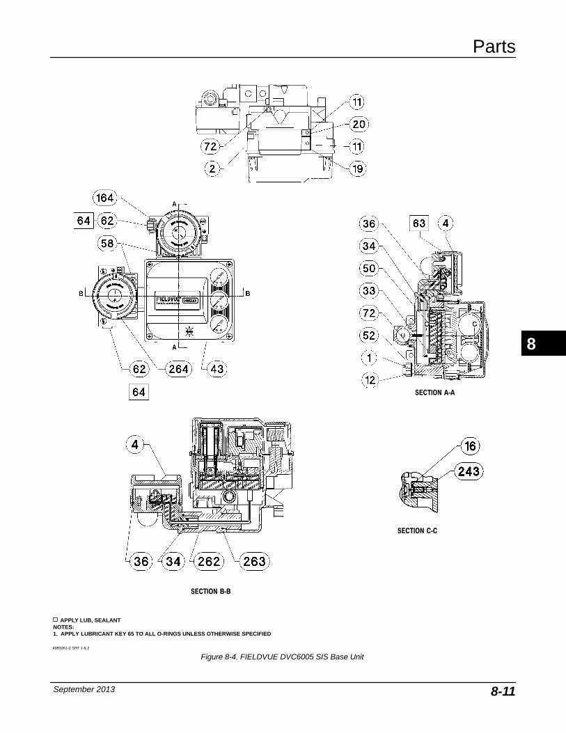
Parts
September 2013 8-11
Figure 8-4. FIELDVUE DVC6005 SIS Base Unit
APPLY LUB, SEALANT
SECTION A‐A
NOTES:1. APPLY LUBRICANT KEY 65 TO ALL O-RINGS UNLESS OTHERWISE SPECIFIED
49B3261-C SHT 1 & 2
SECTION B‐B
SECTION C‐C
8
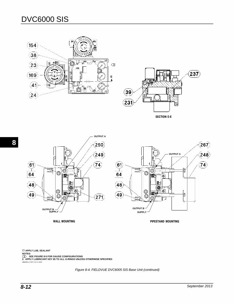
DVC6000 SIS
September 20138-12
Figure 8-4. FIELDVUE DVC6005 SIS Base Unit (continued)
APPLY LUB, SEALANTNOTES:
SEE FIGURE 8-5 FOR GAUGE CONFIGURATIONS2. APPLY LUBRICANT KEY 65 TO ALL O-RINGS UNLESS OTHERWISE SPECIFIED49B3261-C SHT 2 & 3 / DOC
SECTION E‐E
PIPESTAND MOUNTINGWALL MOUNTING
OUTPUT A
SUPPLY
OUTPUT A
SUPPLYOUTPUT B OUTPUT B
1
1
E E
8
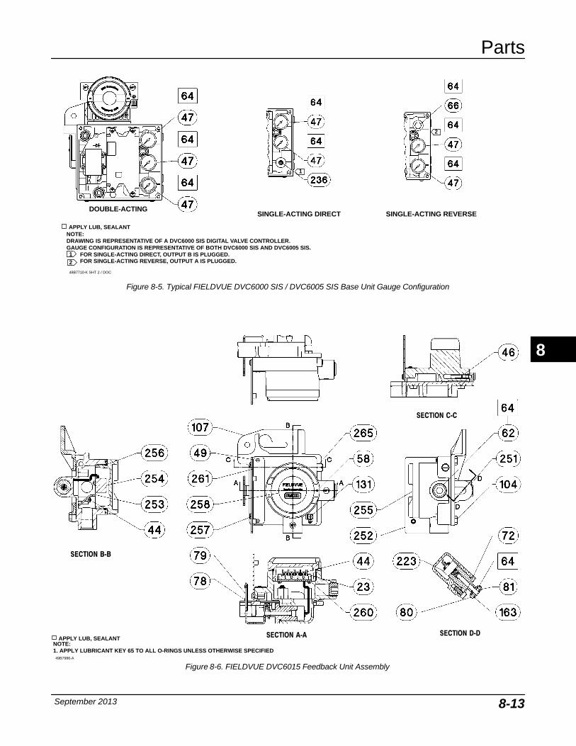
Parts
September 2013 8-13
Figure 8-5. Typical FIELDVUE DVC6000 SIS / DVC6005 SIS Base Unit Gauge Configuration
APPLY LUB, SEALANT
SINGLE-ACTING DIRECT SINGLE-ACTING REVERSEDOUBLE-ACTING
2
1
NOTE:DRAWING IS REPRESENTATIVE OF A DVC6000 SIS DIGITAL VALVE CONTROLLER.GAUGE CONFIGURATION IS REPRESENTATIVE OF BOTH DVC6000 SIS AND DVC6005 SIS.
FOR SINGLE-ACTING DIRECT, OUTPUT B IS PLUGGED.FOR SINGLE-ACTING REVERSE, OUTPUT A IS PLUGGED.
1
2
48B7710-K SHT 2 / DOC
Figure 8-6. FIELDVUE DVC6015 Feedback Unit Assembly
APPLY LUB, SEALANTNOTE: 1. APPLY LUBRICANT KEY 65 TO ALL O-RINGS UNLESS OTHERWISE SPECIFIED
49B7986-A
SECTION A‐A
SECTION B‐B
SECTION D‐D
SECTION C‐C
8
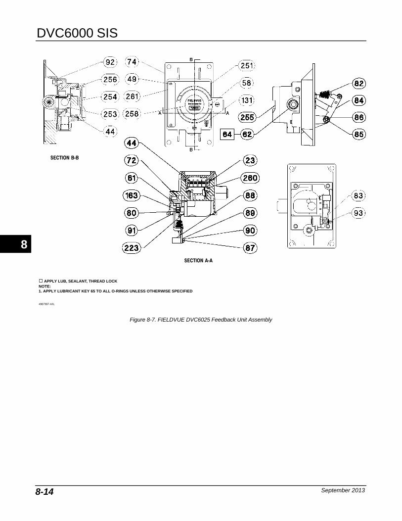
DVC6000 SIS
September 20138-14
Figure 8-7. FIELDVUE DVC6025 Feedback Unit Assembly
49B7987-A/IL
NOTE: 1. APPLY LUBRICANT KEY 65 TO ALL O-RINGS UNLESS OTHERWISE SPECIFIED
APPLY LUB, SEALANT, THREAD LOCK
SECTION A‐A
SECTION B‐B
8

Parts
September 2013 8-15
Figure 8-8. FIELDVUE DVC6035 Feedback Unit Assembly
49B7988-A
NOTE: 1. APPLY LUBRICANT KEY 65 TO ALL O-RINGS UNLESS OTHERWISE SPECIFIED
APPLY LUB, SEALANT, THREAD LOCK
SECTION B‐B
SECTION A‐A
SECTION C‐C
8

DVC6000 SIS
September 20138-16
8
Principle of Operation
September 2013 A-1
A-A-
Appendix A Principle of Operation
HART Communication A-2. . . . . . . . . . . . . . . . . . . . . . . . . . . . . . . . . . . . . . . . . . . . . . . . . .
Digital Valve Controller Operation A-2. . . . . . . . . . . . . . . . . . . . . . . . . . . . . . . . . . . . .
A

DVC6000 SIS
September 2013A-2
Figure A-1. HART Frequency Shift Keying Technique
−0.5 V
+0.5 V
1200 Hz“1”
2200 Hz“0”
AVERAGE CURRENT CHANGE DURING COMMUNICATION = 0
ANALOGSIGNAL
0
A6174
HART Communication The HART (Highway Addressable RemoteTransducer) protocol gives field devices the capabilityof communicating instrument and process datadigitally. This digital communication occurs over thesame two-wire loop that provides the 4-20 mA processcontrol signal, without disrupting the process signal. Inthis way, the analog process signal, with its fasterupdate rate, can be used for control. At the same time,the HART protocol allows access to digital diagnostic,maintenance, and additional process data. Theprotocol provides total system integration via a hostdevice.
The HART protocol uses frequency shift keying (FSK).Two individual frequencies of 1200 and 2200 Hz aresuperimposed over the 4-20 mA current signal. Thesefrequencies represent the digits 1 and 0 (see figureA-1). By superimposing a frequency signal over the4-20 mA current, digital communication is attained.The average value of the HART signal is zero,therefore no DC value is added to the 4-20 mA signal.Thus, true simultaneous communication is achievedwithout interrupting the process signal.
The HART protocol allows the capability ofmulti-dropping, i.e., networking several devices to asingle communications line. This process is well suitedfor monitoring remote applications such as pipelines,custody transfer sites, and tank farms. See table 7-2for instructions on changing the printed wiring boardDIP switch configuration to multi-drop.
Digital Valve Controller Operation The DVC6000 SIS digital valve controller housingcontains the travel sensor, terminal box, pneumaticinput and output connections and a module base thatmay be easily replaced in the field withoutdisconnecting field wiring or tubing. This mastermodule contains the following submodules: I/P
Figure A-2. Typical FIELDVUE Instrument to Personal Computer Connections for ValveLink Software
FIELDTERM.
CONTROL SYSTEM
HARTMODEM
A6761
converter, printed wiring board (pwb) assembly, andpneumatic relay. The module base can be rebuilt byreplacing the submodules. See figures A-3 and A-4.
Process ApplicationsDVC6000 SIS digital valve controllers areloop-powered instruments that provide a control valveposition proportional to an input signal from the controlroom. The following describes a double-actingDVC6010 SIS digital valve controller mounted on apiston actuator.
The input signal is routed into the terminal box througha single twisted pair of wires and then to the printedwiring board assembly submodule where it is read bythe microprocessor, processed by a digital algorithm,and converted into an analog I/P drive signal.
As the input signal increases, the drive signal to theI/P converter increases, increasing the I/P outputpressure. The I/P output pressure is routed to thepneumatic relay submodule. The relay is alsoconnected to supply pressure and amplifies the smallpneumatic signal from the I/P converter. The relayaccepts the amplified pneumatic signal and providestwo output pressures. With increasing input (4 to 20mA signal), the output A pressure always increasesand the output B pressure decreases. The output Apressure is used for double-acting and single-actingdirect applications. The output B pressure is used for
A
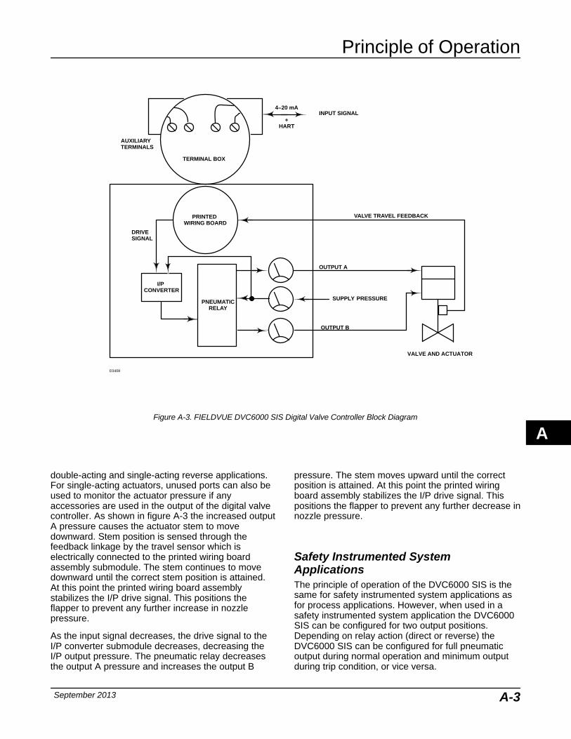
Principle of Operation
September 2013 A-3
Figure A-3. FIELDVUE DVC6000 SIS Digital Valve Controller Block Diagram
E0408
INPUT SIGNAL4−20 mA
+HART
SUPPLY PRESSURE
PRINTED WIRING BOARD
PNEUMATICRELAY
I/P CONVERTER
OUTPUT A
OUTPUT B
AUXILIARYTERMINALS
TERMINAL BOX
DRIVESIGNAL
VALVE AND ACTUATOR
VALVE TRAVEL FEEDBACK
double-acting and single-acting reverse applications.For single-acting actuators, unused ports can also beused to monitor the actuator pressure if anyaccessories are used in the output of the digital valvecontroller. As shown in figure A-3 the increased outputA pressure causes the actuator stem to movedownward. Stem position is sensed through thefeedback linkage by the travel sensor which iselectrically connected to the printed wiring boardassembly submodule. The stem continues to movedownward until the correct stem position is attained.At this point the printed wiring board assemblystabilizes the I/P drive signal. This positions theflapper to prevent any further increase in nozzlepressure.
As the input signal decreases, the drive signal to theI/P converter submodule decreases, decreasing theI/P output pressure. The pneumatic relay decreasesthe output A pressure and increases the output B
pressure. The stem moves upward until the correctposition is attained. At this point the printed wiringboard assembly stabilizes the I/P drive signal. Thispositions the flapper to prevent any further decrease innozzle pressure.
Safety Instrumented SystemApplicationsThe principle of operation of the DVC6000 SIS is thesame for safety instrumented system applications asfor process applications. However, when used in asafety instrumented system application the DVC6000SIS can be configured for two output positions.Depending on relay action (direct or reverse) theDVC6000 SIS can be configured for full pneumaticoutput during normal operation and minimum outputduring trip condition, or vice versa.
A
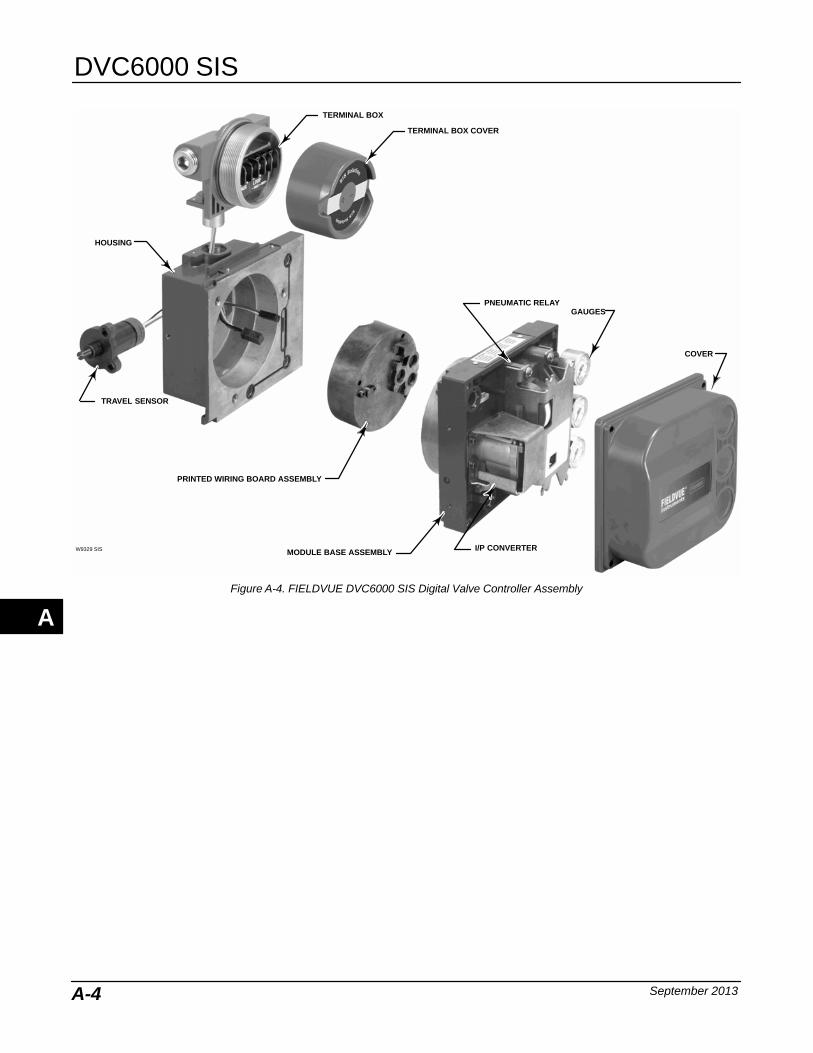
DVC6000 SIS
September 2013A-4
TRAVEL SENSOR
TERMINAL BOX
TERMINAL BOX COVER
MODULE BASE ASSEMBLY
PRINTED WIRING BOARD ASSEMBLY
I/P CONVERTER
PNEUMATIC RELAY
HOUSING
GAUGES
COVER
W9329 SIS
Figure A-4. FIELDVUE DVC6000 SIS Digital Valve Controller Assembly
A

Loop Schematics/Nameplate
September 2013 B-1
B-B-
Appendix B Loop Schematics/Nameplates
B
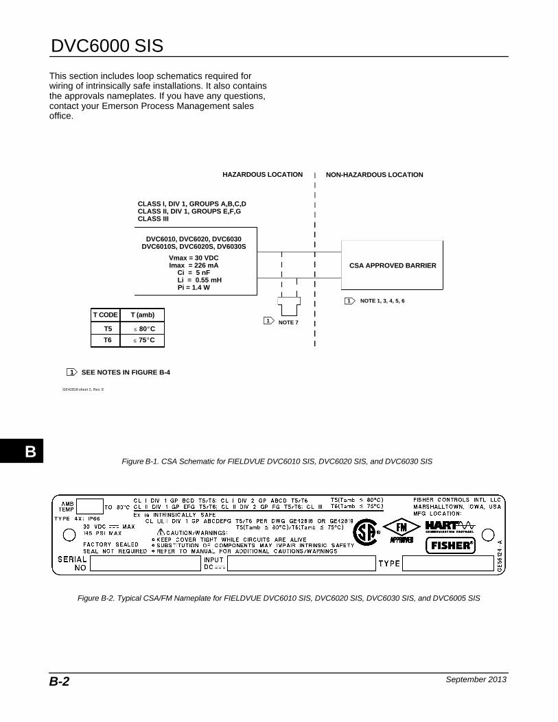
DVC6000 SIS
September 2013B-2
This section includes loop schematics required forwiring of intrinsically safe installations. It also containsthe approvals nameplates. If you have any questions,contact your Emerson Process Management salesoffice.
Figure B-1. CSA Schematic for FIELDVUE DVC6010 SIS, DVC6020 SIS, and DVC6030 SIS
GE42818 sheet 2, Rev. E
CSA APPROVED BARRIER
1 NOTE 1, 3, 4, 5, 6
1 NOTE 7
CLASS I, DIV 1, GROUPS A,B,C,DCLASS II, DIV 1, GROUPS E,F,GCLASS III
DVC6010, DVC6020, DVC6030DVC6010S, DVC6020S, DV6030S
Vmax = 30 VDCImax = 226 mA
Ci = 5 nF Li = 0.55 mH
Pi = 1.4 W
NON-HAZARDOUS LOCATIONHAZARDOUS LOCATION
T6 ≤ 75�C
T5 ≤ 80�C
T CODE T (amb)
1 SEE NOTES IN FIGURE B-4
Figure B-2. Typical CSA/FM Nameplate for FIELDVUE DVC6010 SIS, DVC6020 SIS, DVC6030 SIS, and DVC6005 SIS
B
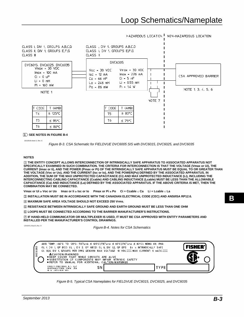
Loop Schematics/Nameplate
September 2013 B-3
Figure B-3. CSA Schematic for FIELDVUE DVC6005 SIS with DVC6015, DVC6025, and DVC6035
1 SEE NOTES IN FIGURE B-4
GE42818 sheet 5, Rev. E
NOTES
� THE ENTITY CONCEPT ALLOWS INTERCONNECTION OF INTRINSICALLY SAFE APPARATUS TO ASSOCIATED APPARATUS NOTSPECIFICALLY EXAMINED IN SUCH COMBINATION. THE CRITERIA FOR INTERCONNECTION IS THAT THE VOLTAGE (Vmax or Ui), THECURRENT (Imax or Ii), AND THE POWER (Pmax or Pi) OF THE INTRINSICALLY SAFE APPARATUS MUST BE EQUAL TO OR GREATER THANTHE VOLTAGE (Voc or Uo), AND THE CURRENT (Isc or Io), AND THE POWER(Po) DEFINED BY THE ASSOCIATED APPARATUS. INADDITION, THE SUM OF THE MAX UNPROTECTED CAPACITANCE (Ci) AND MAX UNPROTECTED INDUCTANCE (Li), INCLUDING THEINTERCONNECTING CABLING CAPACITANCE (Ccable) AND CABLING INDUCTANCE (Lcable) MUST BE LESS THAN THE ALLOWABLECAPACITANCE (Ca) AND INDUCTANCE (La) DEFINED BY THE ASSOCIATED APPARATUS. IF THE ABOVE CRITERIA IS MET, THEN THECOMBINATION MAY BE CONNECTED.
Vmax or Ui � Voc or Uo Imax or Ii � Isc or Io Pmax or Pi � Po Ci + Ccable ≤ Ca Li + Lcable ≤ La
� INSTALLATION MUST BE IN ACCORDANCE WITH THE CANADIAN ELECTRICAL CODE (CEC) AND ANSI/ISA RP12.6.
� MAXIMUM SAFE AREA VOLTAGE SHOULD NOT EXCEED 250 Vrms.
RESISTANCE BETWEEN INTRINSICALLY SAFE GROUND AND EARTH GROUND MUST BE LESS THAN ONE OHM
LOOPS MUST BE CONNECTED ACCORDING TO THE BARRIER MANUFACTURER’S INSTRUCTIONS.
� IF HAND-HELD COMMUNICATOR OR MULTIPLEXER IS USED, IT MUST BE CSA APPROVED WITH ENTITY PARAMETERS ANDINSTALLED PER THE MANUFACTURER’S CONTROL DRAWINGS.
GE42818, Sheet 8, Rev. D
Figure B-4. Notes for CSA Schematics
Figure B-5. Typical CSA Nameplates for FIELDVUE DVC6015, DVC6025, and DVC6035
B

DVC6000 SIS
September 2013B-4
Figure B-6. FM Schematic for FIELDVUE DVC6010 SIS, DVC6020 SIS, and DVC6030 SIS Digital Valve Controllers
GE42819 Sheet 2, Rev. D
FM APPROVED BARRIER
1 NOTE 1, 3, 4, 5, 6
1 NOTE 7
I.S. CLASS I,II,III, DIV 1, GROUPS A,B,C,D,E,F,GN.I. CLASS I, DIV 2, GROUPS A,B,C,D
DVC6010, DVC6020, DVC6030DVC6010S, DVC6020S,
DV6030S
Vmax = 30 VDCImax = 226 mA
Ci = 5 nF Li = 0.55 mH
Pi = 1.4 W
NON-HAZARDOUS LOCATIONHAZARDOUS LOCATION
1 SEE NOTES IN FIGURE B-8
T6 ≤ 75�C
T5 ≤ 80�C
T CODE T (amb)
GE42819 Sheet 5, Rev. D
1
11
1 SEE NOTES IN FIGURE B-8
Figure B-7. FM Schematic for FIELDVUE DVC6005 SIS with DVC6015, DVC6025, and DVC6035
B
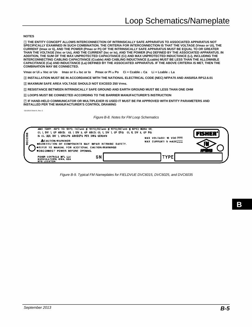
Loop Schematics/Nameplate
September 2013 B-5
NOTES
� THE ENTITY CONCEPT ALLOWS INTERCONNECTION OF INTRINSICALLY SAFE APPARATUS TO ASSOCIATED APPARATUS NOTSPECIFICALLY EXAMINED IN SUCH COMBINATION. THE CRITERIA FOR INTERCONNECTION IS THAT THE VOLTAGE (Vmax or Ui), THECURRENT (Imax or Ii), AND THE POWER (Pmax or Pi) OF THE INTRINSICALLY SAFE APPARATUS MUST BE EQUAL TO OR GREATERTHAN THE VOLTAGE (Voc or Uo), AND THE CURRENT (Isc or Io), AND THE POWER (Po) DEFINED BY THE ASSOCIATED APPARATUS. INADDITION, THE SUM OF THE MAX UNPROTECTED CAPACITANCE (Ci) AND MAX UNPROTECTED INDUCTANCE (Li), INCLUDING THEINTERCONNECTING CABLING CAPACITANCE (Ccable) AND CABLING INDUCTANCE (Lcable) MUST BE LESS THAN THE ALLOWABLECAPACITANCE (Ca) AND INDUCTANCE (La) DEFINED BY THE ASSOCIATED APPARATUS. IF THE ABOVE CRITERIA IS MET, THEN THECOMBINATION MAY BE CONNECTED.
Vmax or Ui � Voc or Uo Imax or Ii � Isc or Io Pmax or Pi � Po Ci + Ccable ≤ Ca Li + Lcable ≤ La
� INSTALLATION MUST BE IN ACCORDANCE WITH THE NATIONAL ELECTRICAL CODE (NEC) NFPA70 AND ANSI/ISA RP12.6.01
� MAXIMUM SAFE AREA VOLTAGE SHOULD NOT EXCEED 250 Vrms.
RESISTANCE BETWEEN INTRINSICALLY SAFE GROUND AND EARTH GROUND MUST BE LESS THAN ONE OHM
LOOPS MUST BE CONNECTED ACCORDING TO THE BARRIER MANUFACTURER’S INSTRUCTION
� IF HAND-HELD COMMUNICATOR OR MULTIPLEXER IS USED IT MUST BE FM APPROVED WITH ENTITY PARAMETERS ANDINSTALLED PER THE MANUFACTURER’S CONTROL DRAWING
GE42819 Sheet 8, Rev. E
Figure B-8. Notes for FM Loop Schematics
Figure B-9. Typical FM Nameplates for FIELDVUE DVC6015, DVC6025, and DVC6035
B
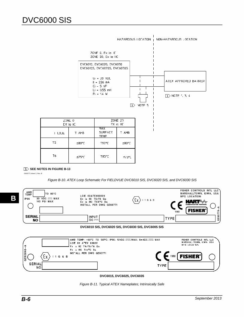
DVC6000 SIS
September 2013B-6
GE60771 sheet 3, Rev. B
1 SEE NOTES IN FIGURE B-13
1
1
Figure B-10. ATEX Loop Schematic For FIELDVUE DVC6010 SIS, DVC6020 SIS, and DVC6030 SIS
Figure B-11. Typical ATEX Nameplates; Intrinsically Safe
DVC6010 SIS, DVC6020 SIS, DVC6030 SIS, DVC6005 SIS
DVC6015, DVC6025, DVC6035
B
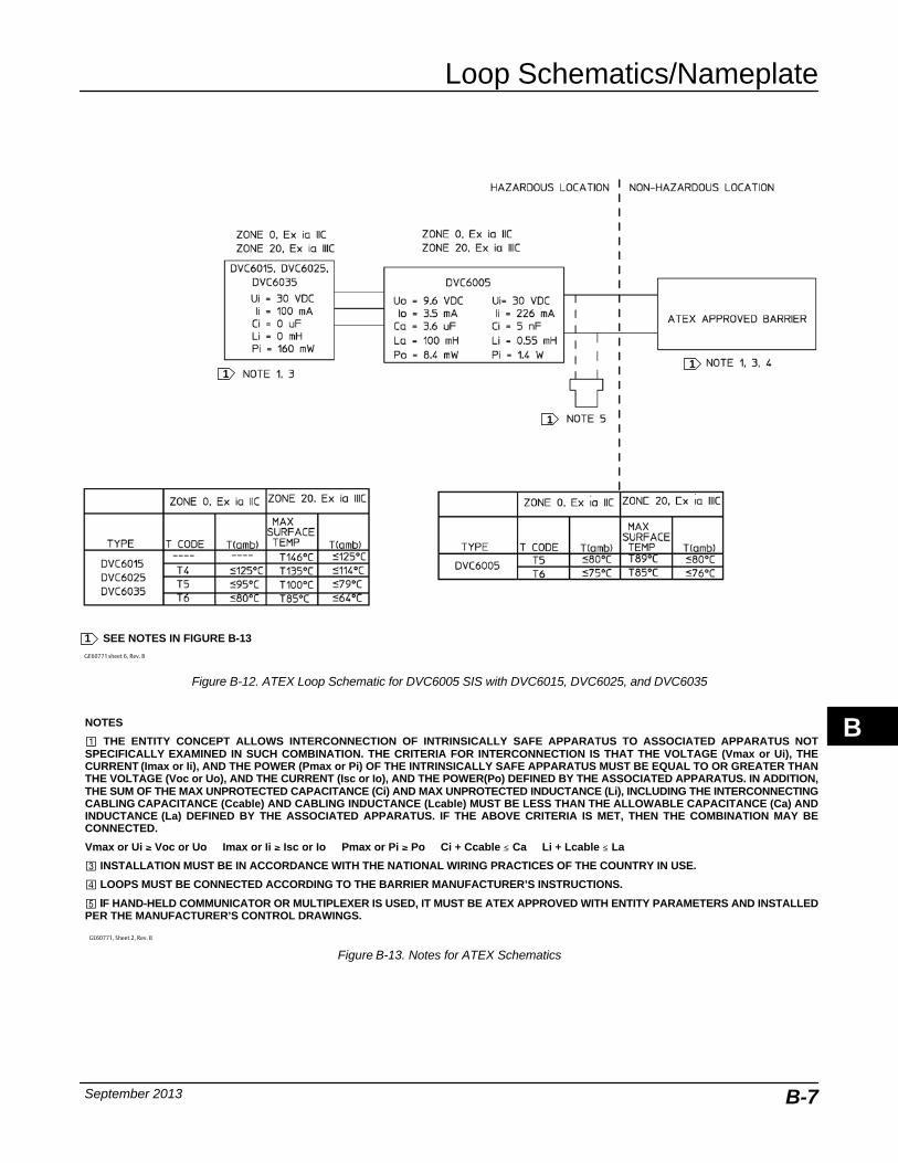
Loop Schematics/Nameplate
September 2013 B-7
GE60771 sheet 6, Rev. B
1 SEE NOTES IN FIGURE B-13
1
11
Figure B-12. ATEX Loop Schematic for DVC6005 SIS with DVC6015, DVC6025, and DVC6035
NOTES
� THE ENTITY CONCEPT ALLOWS INTERCONNECTION OF INTRINSICALLY SAFE APPARATUS TO ASSOCIATED APPARATUS NOTSPECIFICALLY EXAMINED IN SUCH COMBINATION. THE CRITERIA FOR INTERCONNECTION IS THAT THE VOLTAGE (Vmax or Ui), THECURRENT (Imax or Ii), AND THE POWER (Pmax or Pi) OF THE INTRINSICALLY SAFE APPARATUS MUST BE EQUAL TO OR GREATER THANTHE VOLTAGE (Voc or Uo), AND THE CURRENT (Isc or Io), AND THE POWER(Po) DEFINED BY THE ASSOCIATED APPARATUS. IN ADDITION,THE SUM OF THE MAX UNPROTECTED CAPACITANCE (Ci) AND MAX UNPROTECTED INDUCTANCE (Li), INCLUDING THE INTERCONNECTINGCABLING CAPACITANCE (Ccable) AND CABLING INDUCTANCE (Lcable) MUST BE LESS THAN THE ALLOWABLE CAPACITANCE (Ca) ANDINDUCTANCE (La) DEFINED BY THE ASSOCIATED APPARATUS. IF THE ABOVE CRITERIA IS MET, THEN THE COMBINATION MAY BECONNECTED.
Vmax or Ui � Voc or Uo Imax or Ii � Isc or Io Pmax or Pi � Po Ci + Ccable ≤ Ca Li + Lcable ≤ La
� INSTALLATION MUST BE IN ACCORDANCE WITH THE NATIONAL WIRING PRACTICES OF THE COUNTRY IN USE.
� LOOPS MUST BE CONNECTED ACCORDING TO THE BARRIER MANUFACTURER’S INSTRUCTIONS.
IF HAND-HELD COMMUNICATOR OR MULTIPLEXER IS USED, IT MUST BE ATEX APPROVED WITH ENTITY PARAMETERS AND INSTALLEDPER THE MANUFACTURER’S CONTROL DRAWINGS.
GE60771, Sheet 2, Rev. B
Figure B-13. Notes for ATEX Schematics
B
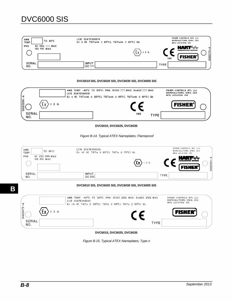
DVC6000 SIS
September 2013B-8
DVC6010 SIS, DVC6020 SIS, DVC6030 SIS, DVC6005 SIS
Figure B-14. Typical ATEX Nameplates; Flameproof
DVC6015, DVC6025, DVC6035
DVC6010 SIS, DVC6020 SIS, DVC6030 SIS, DVC6005 SIS
Figure B-15. Typical ATEX Nameplates; Type n
DVC6015, DVC6025, DVC6035
B
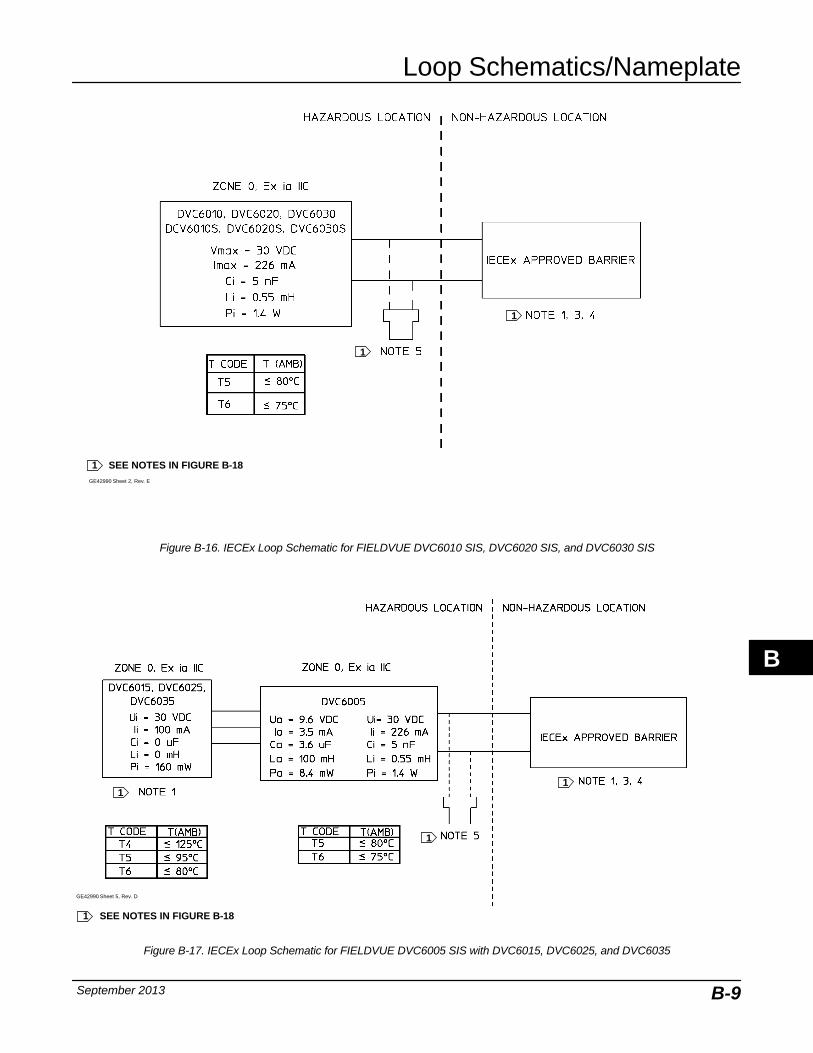
Loop Schematics/Nameplate
September 2013 B-9
GE42990 Sheet 2, Rev. E
1 SEE NOTES IN FIGURE B-18
1
1
Figure B-16. IECEx Loop Schematic for FIELDVUE DVC6010 SIS, DVC6020 SIS, and DVC6030 SIS
GE42990 Sheet 5, Rev. D
1 SEE NOTES IN FIGURE B-18
1
1
1
Figure B-17. IECEx Loop Schematic for FIELDVUE DVC6005 SIS with DVC6015, DVC6025, and DVC6035
B
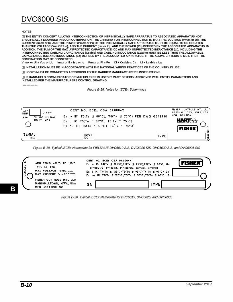
DVC6000 SIS
September 2013B-10
GE42990 Sheet 8, Rev.
NOTES
� THE ENTITY CONCEPT ALLOWS INTERCONNECTION OF INTRINSICALLY SAFE APPARATUS TO ASSOCIATED APPARATUS NOTSPECIFICALLY EXAMINED IN SUCH COMBINATION. THE CRITERIA FOR INTERCONNECTION IS THAT THE VOLTAGE (Vmax or Ui), THECURRENT (Imax or Ii), AND THE POWER (Pmax or Pi) OF THE INTRINSICALLY SAFE APPARATUS MUST BE EQUAL TO OR GREATERTHAN THE VOLTAGE (Voc OR Uo), AND THE CURRENT (Isc or Io), AND THE POWER (Po) DEFINED BY THE ASSOCIATED APPARATUS. INADDITION, THE SUM OF THE MAX UNPROTECTED CAPACITANCE (Ci) AND MAX UNPROTECTED INDUCTANCE (Li), INCLUDING THEINTERCONNECTING CABLING CAPACITANCE (Ccable) AND CABLING INDUCTANCE (Lcable) MUST BE LESS THAN THE ALLOWABLECAPACITANCE (Ca) AND INDUCTANCE (La) DEFINED BY THE ASSOCIATED APPARATUS. IF THE ABOVE CRITERIA IS MET, THEN THECOMBINATION MAY BE CONNECTED.Vmax or Ui � Voc or Uo Imax or Ii � Isc or Io Pmax or Pi � Po Ci + Ccable ≤ Ca Li + Lcable ≤ La
� INSTALLATION MUST BE IN ACCORDANCE WITH THE NATIONAL WIRING PRACTICES OF THE COUNTRY IN USE
� LOOPS MUST BE CONNECTED ACCORDING TO THE BARRIER MANUFACTURER’S INSTRUCTIONS
IF HAND-HELD COMMUNICATOR OR MULTIPLEXER IS USED IT MUST BE IECEx APPROVED WITH ENTITY PARAMETERS ANDINSTALLED PER THE MANUFACTURERS CONTROL DRAWING
Figure B-18. Notes for IECEx Schematics
Figure B-19. Typical IECEx Nameplate for FIELDVUE DVC6010 SIS, DVC6020 SIS, DVC6030 SIS, and DVC6005 SIS
Figure B-20. Typical IECEx Nameplate for DVC6015, DVC6025, and DVC6035
B
Glossary
September 2013 Glossary-1
GlossaryAlert Point
An adjustable value that, when exceeded,activates an alert.
AlgorithmA set of logical steps to solve a problem oraccomplish a task. A computer program containsone or more algorithms.
AlphanumericConsisting of letters and numbers.
Analog Input UnitsUnits in which the analog input is displayed andmaintained in the instrument.
ANSI (acronym)The acronym ANSI stands for the AmericanNational Standards Institute
ANSI ClassValve pressure/temperature rating.
Auto TestThe digital valve controller can be configured toautomatically run the partial stroke test.
Auxiliary Input AlertChecks the status of the auxiliary input; a discreteinput. When enabled, the Auxiliary Input Alert isactive when the auxiliary input terminals are openor closed (shorted), depending upon the selectionfor Auxiliary Input Alert State.
Auxiliary Terminal (Indicator)Indicates whether auxiliary wiring terminals areopen or closed (such as by an external switchcontact).
Bench SetPressure, supplied to an actuator, required todrive the actuator through rated valve travel.Expressed in pounds per square inch.
ByteA unit of binary digits (bits). A byte consists ofeight bits.
Calibration LocationWhere the instrument was last calibrated; eitherin the factory or in the field.
ConfigurationStored instructions and operating parameters fora FIELDVUE instrument.
Control LoopAn arrangement of physical and electroniccomponents for process control. The electroniccomponents of the loop continuously measureone or more aspects of the process, then alterthose aspects as necessary to achieve a desiredprocess condition. A simple control loopmeasures only one variable. More sophisticatedcontrol loops measure many variables andmaintain specified relationships among thosevariables.
Control ModeDefines where the instrument reads its set point.The following control modes are available for aFIELDVUE instrument:Analog The instrument receives its travel setpoint over the 4-20 mA loop. Digital The instrument receives its set pointdigitally, via the HART communications link.Test This is not a user-selectable mode. TheField Communicator or AMS ValveLink Softwareplaces the instrument in this mode whenever itneeds to move the valve, such as for calibrationor diagnostic tests.
Control Mode, RestartDetermines the instrument control mode after arestart. See Control Mode for the available restartcontrol modes.
Glossary
DVC6000 SIS
September 2013Glossary-2
ControllerA device that operates automatically to regulate acontrolled variable.
Crossover PointThe point at which the feedback pin is closest tothe axis of rotation of the travel sensor. A visualindication of the crossover point is found whenthe slot in the instrument feedback arm forms a90-degree angle with the valve stem.
Current-to-Pressure (I/P) ConverterAn electronic component or device that convertsa milliamp signal to a proportional pneumaticpressure output signal.
Cycle CounterThe capability of a FIELDVUE instrument torecord the number of times the travel changesdirection. The change in direction must occurafter the deadband has been exceeded before itcan be counted as a cycle.
Cycle Counter AlertChecks the difference between the Cycle Counterand the Cycle Counter Alert Point. Cycle CounterAlert is active when the cycle counter valueexceeds the Cycle Counter Alert Point. It clearsafter you reset the Cycle Counter to a value lessthan the alert point.
Cycle Counter Alert PointAn adjustable value which, when exceeded,activates the Cycle Counter Alert. Valid entriesare 0 to 4 billion cycles.
Cycle Counter DeadbandRegion around the travel reference point, inpercent of ranged travel, established at the lastincrement of the Cycle Counter. The deadbandmust be exceeded before a change in travel canbe counted as a cycle. Valid entries are 0% to100%. Typical value is between 2% and 5%.
DeviationUsually, the difference between set point andprocess variable. More generally, any departurefrom a desired or expected value or pattern.
Device IDUnique identifier embedded in the instrument atthe factory.
Device RevisionRevision number of the interface software thatpermits communication between the FieldCommunicator and the instrument.
Drive SignalThe signal to the I/P converter from the printedwiring board. It is the percentage of the totalmicroprocessor effort needed to drive the valvefully open.
Drive Signal AlertChecks the drive signal and calibrated travel. Ifone of the following conditions exists for morethan 20 seconds, the Drive Signal Alert is active.If none of the conditions exist, the alert is cleared.If Zero Power Condition = Closed
The alert is active when:
drive signal <10% and calibrated travel >3%
drive signal >90% and calibrated travel <97%
If Zero Power Condition = Open
The alert is active when:
drive signal <10% and calibrated travel <97%
drive signal >90% and calibrated travel >3%
DVC Power UpDefines the power up behavior of the DVC6000.Auto Reset allows the valve to track thecommand signal when power is applied to thedevice. Manual Reset will lock the device in itssafety position until the digital valve controller isreset.
Equal PercentageA valve flow characteristic where equalincrements of valve stem travel produce equalpercentage changes in existing flow. One of theinput characteristics available for a FIELDVUEdigital valve controller. See also, Linear andQuick Opening.
Feedback ArmThe mechanical connection between the valvestem linkage and the FIELDVUE digital valvecontroller travel sensor.
Feedback ConnectionIdentifies the type of feedback linkage: rotary,sliding-stem roller or sliding-stem standard.
Glossary
Glossary
September 2013 Glossary-3
Feedback SignalIndicates to the instrument the actual position ofthe valve. The travel sensor provides thefeedback signal to the instrument printed wiringboard assembly. A mechanical linkage connectsthe travel sensor to the valve stem or shaft.
Firmware RevisionThe revision number of the instrument firmware.Firmware is a program that is entered into theinstrument at time of manufacture and cannot bechanged by the user.
Free TimePercent of time that the microprocessor is idle. Atypical value is 25%. The actual value dependson the number of functions in the instrument thatare enabled and on the amount of communicationcurrently in progress.
Full Ranged TravelCurrent, in mA, that corresponds with the pointwhere ranged travel is maximum, i.e., limited bythe mechanical travel stops.
GainThe ratio of output change to input change.
Hardware RevisionRevision number of the instrument hardware. Thephysical components of the instrument aredefined as the hardware.
HART (acronym)The acronym HART stands for HighwayAddressable Remote Transducer.
HART TagAn eight-character name that identifies thephysical instrument.
HART Universal RevisionRevision number of the HART UniversalCommands which are the communicationsprotocol for the instrument.
Input CharacteristicThe relationship between the ranged travel andranged input. Possible values include: linear,equal percentage, and quick opening.
Input CurrentThe current signal from the control system thatserves as the analog input to the instrument. Seealso Input Signal.
Input RangeThe analog input signal range that corresponds tothe travel range.
Input SignalThe current signal from the control system. Theinput signal can be displayed in milliamperes or inpercent of ranged input.
Instrument LevelDetermines the functions available for theinstrument.
Instrument ModeDetermines if the instrument responds to itsanalog input signal. There are two instrumentmodes:In Service: For a fully functioning instrument, theinstrument output changes in response to analoginput changes. Typically changes to setup orcalibration cannot be made when the instrumentmode is In Service.Out of Service: The instrument output does notchange in response to analog input changeswhen the instrument mode is Out of Service.Some setup parameters can be changed onlywhen the instrument mode is Out of Service.
Instrument ProtectionDetermines if commands from a HART devicecan calibrate and/or configure certain parametersin the instrument. There are two types ofinstrument protection:Configuration and Calibration: Prohibitschanging protected setup parameters; prohibitscalibration.None: Permits both configuration and calibration.The instrument is “unprotected.”
Instrument Serial NumberThe serial number assigned to the printed wiringboard by the factory but can be changed duringsetup. The instrument serial number shouldmatch the serial number on the instrumentnameplate.
Glossary
DVC6000 SIS
September 2013Glossary-4
Leak ClassDefines the allowable leakage by a valve when itis closed. Leak class numbers are listed in twostandards: ANSI/FCI 70-2 and IEC 534-4.
LinearA valve flow characteristic where changes in flowrate are directly proportional to changes in valvestem travel. One of the input characteristicsavailable for a FIELDVUE digital valve controller.See also, Equal Percentage and Quick Opening.
Linearity, dynamicLinearity (independent) is the maximum deviationfrom a straight line best fit to the opening andclosing curves and a line representing theaverage value of those curves.
Local Control PanelThe LCP100 local control panel is used with theFIELDVUE DVC6000 SIS digital valve controller.This panel is used to monitor and manually openand close a safety shutdown valve. The LCP100also provides a manual reset feature and a buttonfor initiating a partial stroke test.
Manual ResetThe DVC6000 SIS digital valve controller can beconfigured to hold the trip state until a local resetbutton is pressed.
MemoryA type of semiconductor used for storingprograms or data. FIELDVUE instruments usethree types of memory: Random Access Memory(RAM), Read Only Memory (ROM), andNon-Volatile Memory (NVM). See also theselistings in this glossary.
MenuA list of programs, commands, or other activitiesthat you select by using the arrow keys tohighlight the item then pressing ENTER, or byentering the numeric value of the menu item.
Minimum Closing TimeMinimum time, in seconds, for the travel todecrease through the entire ranged travel. Thisrate is applied to any travel decrease. Validentries are 0 to 400 seconds. Deactivate byentering a value of 0 seconds.
Minimum Opening TimeMinimum time, in seconds, for the travel toincrease through the entire ranged travel. Thisrate is applied to any travel increase. Because offriction, actual valve travel may not respond inexactly the same time frame. Valid entries are 0to 400 seconds. Deactivate by entering a value of0 seconds.
Non-Volatile Memory (NVM)A type of semiconductor memory that retains itscontents even though power is disconnected.NVM contents can be changed duringconfiguration unlike ROM which can be changedonly at time of instrument manufacture. NVMstores configuration restart data.
ParallelSimultaneous: said of data transmission on two ormore channels at the same time.
Polling AddressAddress of the instrument. If the digital valvecontroller is used in a point-to-point configuration,set the polling address to 0. If it is used in amultidrop configuration, or split range application,set the polling address to a value from 0 to 15.
Pressure SensorA FIELDVUE instrument internal device thatsenses pneumatic pressure. DVC6000 SIS digitalvalve controllers have three pressure sensors:one to sense supply pressure and two to sensethe output pressures.
Primary MasterMasters are communicating devices. A primarymaster is a communicating device permanentlywired to a field instrument. Typically, aHART-compatible control system or a computerrunning AMS ValveLink Software is the primarymaster.
In contrast, a secondary master is not oftenpermanently wired to a field instrument. TheModel 375 Field Communicator or a computerrunning ValveLink software communicatingthrough a HART modem could be considered asecondary master.
Note: If one type of master takes an instrumentOut Of Service, the same type must put it InService. For example, if a device set up as aprimary master takes an instrument Out OfService, a device set up as a primary mastermust be used to place the instrument In Service.
Glossary
Glossary
September 2013 Glossary-5
Quick OpeningA valve flow characteristic where most of thechange in flow rate takes place for small amountsof stem travel from the closed position. The flowcharacteristic curve is basically linear through thefirst 40 percent of stem travel. One of the inputcharacteristics available for a FIELDVUE digitalvalve controller. See also, Equal Percentage andLinear.
Random Access Memory (RAM)A type of semiconductor memory that is normallyused by the microprocessor during normaloperation that permits rapid retrieval and storageof programs and data. See also Read OnlyMemory (ROM) and Non-Volatile Memory (NVM).
RateAmount of change in output proportional to therate of change in input.
Read-Only Memory (ROM)A memory in which information is stored at thetime of instrument manufacture. You canexamine but not change ROM contents.
Seat LoadForce exerted on the valve seat, typicallyexpressed in pounds force per lineal inch of portcircumference. Seat load is determined by shutoffrequirements.
Set Point Filter TimeThe time constant, in seconds, for the first-orderinput filter.
SoftwareMicroprocessor or computer programs androutines that reside in alterable memory (usuallyRAM), as opposed to firmware, which consists ofprograms and routines that are programmed intomemory (usually ROM) when the instrument ismanufactured. Software can be manipulatedduring normal operation, firmware cannot.
Stroking TimeThe time, in seconds, required to move the valvefrom its fully open position to fully closed, or viceversa.
Temperature SensorA device within the FIELDVUE instrument thatmeasures the instrument’s internal temperature.
TravelMovement of the valve stem or shaft whichchanges the amount the valve is open or closed.
Travel AccumulatorThe capability of a FIELDVUE instrument torecord total change in travel. The value of theTravel Accumulator increments when themagnitude of the change exceeds the TravelAccumulator Deadband. To reset the TravelAccumulator, set it to zero.
Travel Accumulator AlertChecks the difference between the TravelAccumulator value and the Travel AccumulatorAlert Point. The Travel Accumulator Alert is activewhen the Travel Accumulator value exceeds theTravel Accumulator Alert Point. It clears after youreset the Travel Accumulator to a value less thanthe alert point.
Travel Accumulator Alert PointAn adjustable value which, when exceeded,activates the Travel Accumulator Alert. Validentries are 0% to 4 billion %.
Travel Accumulator DeadbandRegion around the travel reference pointestablished at the last increment of theaccumulator. This region must be exceededbefore a change in travel can be accumulated.Valid entries are 0% to 100%.
Travel AlertChecks the ranged travel against the travel highand low alert points. The travel alert is active ifeither the high or low point is exceeded. Once ahigh or low point is exceeded, the ranged travelmust clear that point by the Travel AlertDeadband before the alert clears. Four travelalerts are available: Travel Alert Hi, Travel AlertLo, Travel Alert Hi Hi, and Travel Alert Lo Lo.
Travel Alert DeadbandTravel, in percent of ranged travel, required toclear a travel alert, once it is active. Valid entriesare −25% to 125%.
Glossary
DVC6000 SIS
September 2013Glossary-6
Travel Alert High PointValue of the travel, in percent of ranged travel,which, when exceeded, sets the Travel Alert Hialert. Valid entries are −25% to 125%.
Travel Alert High High PointValue of the travel, in percent of ranged travel,which, when exceeded, sets the Travel Alert Hi Hialert. Valid entries are −25% to 125%.
Travel Alert Low PointValue of the travel, in percent of ranged travel,which, when exceeded, sets the Travel Alert Loalert. Valid entries are −25% to 125%.
Travel Alert Low Low PointValue of the travel, in percent of ranged travel,which, when exceeded, sets the Travel Alert LoLo alert. Valid entries are −25% to 125%.
Travel CutoffDefines the cutoff point for the travel, in percentof ranged travel. There are two travel cutoffs:high and low. Once travel exceeds the cutoff, thedrive signal is set to either maximum or minimum,depending on the aero power condition and if thecutoff is high or low. Minimum opening time orminimum closing time are not in effect while thetravel is beyond the cutoff. Use the travel cutoff toobtain the desired seat load or to be sure thevalve is fully open.
Travel DeviationThe difference between the analog input signal (inpercent of ranged input), the “target” travel, andthe actual “ranged” travel.
Travel Deviation AlertChecks the difference between the target and theranged travel. If the difference exceeds the TravelDeviation Alert Point for more than the TravelDeviation Time, the Travel Deviation Alert isactive. It remains active until the difference is lessthan the Travel Deviation Alert Point.
Travel Deviation Alert PointAn adjustable value for the target travel and theranged travel difference, expressed in percent,When this value is exceeded by the traveldeviation for more than the Travel DeviationTime, the Travel Deviation Alert is active. Validentries are 0% to 100%. Typically this is set to5%.
Travel Deviation TimeThe time, in seconds. that the travel deviationmust exceed the Travel Deviation Alert Pointbefore the alert is active. Valid entries are 1 to 60seconds.
Travel LimitA setup parameter that defines the maximumallowable travel (in percent of ranged travel) forthe valve. During operation, the travel target willnot exceed this limit. There are two travel limits:high and low. Typically the travel limit low will beused to keep the valve from going completelyclosed.
Travel RangeTravel, in percent of calibrated travel, thatcorresponds to the input range.
Travel SensorA device within the FIELDVUE instrument thatsenses valve stem or shaft movement. The travelsensor is mechanically connected to the valvestem or shaft.
Travel Sensor MotionEstablishes motion of the travel sensor. Whileviewing the end of the travel sensor shaft, ifincreasing air pressure to the actuator causes theshaft to rotate clockwise, travel sensor motion isCW. If increasing air pressure causes the shaft torotate counterclockwise, travel sensor motion isCCW.
TuningThe adjustment of control terms or parametervalues to produce a desired control effect.
Tuning SetPreset values that identify gain settings for aFIELDVUE instrument. The tuning set and supplypressure together determine an instrument’sresponse to input signal changes.
Glossary
Glossary
September 2013 Glossary-7
Watch Dog TimerA timer that the microprocessor must rearmperiodically. If the microprocessor is unable torearm the timer, the instrument goes throughreset.
Zero Power ConditionThe position of the valve when the power to thepositioner is turned off. It is used to reference 0%travel. For Relay A and C, Port A will be atatmosphere pressure, and if double-acting, Port Bwill be at supply pressure. For Relay B, Port Bwill be at supply pressure.
Glossary

DVC6000 SIS
September 2013Glossary-8
Glossary
Index
September 2013 Index-1
Index
AAction on Failed Test, 4-22
Actuator Style, 4-19
adjustment arm, 2-7
Alert Conditions, 6-2Alert Record, 6-3Electronics, 6-2Environment, 6-3Sensor, 6-2SIS, 6-3Travel, 6-3Travel History, 6-3
Alert Groups, 4-17Failure Alerts, 4-17Miscellaneous, 4-17Valve Alerts, 4-17
Alert Record, 4-17
Alerts, 4-13Alert Record, 4-17
Alert Groups, 4-17Enabling Alert Groups, 4-17
Electronic, 4-13Drive Signal Alert, 4-13Processor Impaired Alerts, 4-13
Environment, 4-14Environmental
Aux Terminal Alerts, 4-14Supply Press Lo Alert, 4-14
Sensor, 4-14SIS, 4-16Travel, 4-14
Deviation Alert, 4-14Limit Alerts, 4-15Travel Limit Hi/Lo Alerts, 4-15Travel Limit/Cutoff Alerts, 4-15
Travel History, 4-15Cycle Count, 4-15Cycle Count/Tvl Accum Deadband, 4-16Tvl Accum, 4-16
Analog Calibration Adjust, 5-4
Analog InputDisplaying Value, 6-8Units, 4-18
Analog Input Calibration, 5-10
Analog Input Range, 4-18
ASCO Solenoid Valve, 2-33
ATEXHazardous Area Classifications, 1-10, 1-11Loop Schematic, B-6, B-7Nameplates, B-6, B-8Special Conditions for Safe Use, 2-5
Auto Calibrate Travel, 5-3Error Messages, 5-4
Auto Test Interval , View/Edit, 4-22
Aux Term Mode , 4-19
Auxiliary Input, Displaying Status, 6-8
Auxiliary Terminal, 6-5Local DI, 6-5Wiring Length Guidelines, 6-5
Auxiliary Terminal Alert, 4-14
auxiliary terminal button, 4-10
Bbias spring, 2-7, 2-14
Burst Mode, 4-3Commands, 4-4Enabling, 4-3
CCalibration
Analog Input, 5-10Auto Calibrate Travel, 5-3
Error Messages, 5-4Manual Calibrate Travel, 5-4Pressure Sensors, 5-6PST, 5-12Relay Adjustment, 5-10
Index

DVC6000 SIS
September 2013Index-2
Sensor Calibration, 5-6Pressure Sensors, 5-6
TravelAuto, 5-3Manual, 5-4
Analog Calibration Adjust, 5-4Digital Calibration Adjust, 5-5
Travel Sensor, 5-7Travel Sensor Adjust, 5-7
Calibration , Travel, 5-3
Calibration & Diagnostics, 4-17
Calibration Status and Location, 4-19
Classifications/Certifications, 1-5
Communication Cable Capacitance, 2-29
Communication Connections, 2-28
ConnectionsElectrical
4−20 mA Loop, 2-23Communication, 2-28Test, 2-28
PneumaticOutput, 2-20Supply, 2-18
Pressure, 2-18Vent, 2-22
Control Mode, 4-3
Control System RequirementsCompliance Voltage, 2-29Voltage Available, 2-28
Critical NVM Shutdown, 4-13
CSAHazardous Area Classifications, 1-8Loop Schematics, B-2
DVC6005 SIS, B-3Nameplates, B-2, B-3Special Conditions of Safe Use, 2-4
Custom Characterization Table, 4-12
Cycle Count, 4-15
Cycle CounterDisplaying Value, 6-8Enabling Alert, 4-16Resetting, 4-16
DDate, 4-18, 4-19
DD Information, 6-9
Declaration of SEP, 1-6
Demand Mode Tests, 6-6Point-to-Point Mode, 6-6when LCP100 is used, 6-7
Description, DVC6000 Series, 1-2
Descriptor, 4-18
Detailed Setup, 4-2
Device ID, Device Information, 6-9
Device Information, 6-9
Device Power Up, 4-22
Device Record, 6-4
Device Revision, 6-9
Device Variables, 6-8Device, 6-8
Digital Calibration Adjust, 5-5
DIP Switch, 2-31Setting, 7-6
Double-Acting Actuators, Output Connections,2-20
Drive Current Shutdown, 4-13
Drive Signal, 4-13Displaying Value, 6-8
Drive Signal Alert, 4-13
Dynamic Response, 4-12
EEducational Services, 1-7
EF8316G303, ASCO solenoid valve, 2-31,2-33, 2-34
EF8316G304, ASCO solenoid valve, 2-31,2-33, 2-34
EFX8551G305 103594, ASCO solenoid valve,2-31, 2-32, 2-33, 2-34, 2-35
EFX8553G305 103594, ASCO solenoid valve,2-31, 2-32, 2-33, 2-34, 2-35
Electrical Classification, 1-5
Electrical Connections, LCP100 local controlpanel, 2-35
Electromagnetic Immunity Performance, 1-8
Electromagnetic Interference, 1-5
Emergency Mode Tests, Multidrop Mode, 6-6
End Point Pressure Control, 4-11
Index
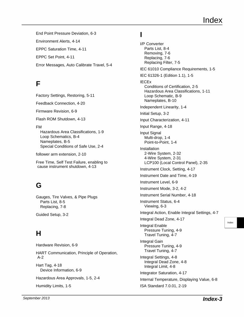
Index
September 2013 Index-3
End Point Pressure Deviation, 6-3
Environment Alerts, 4-14
EPPC Saturation Time, 4-11
EPPC Set Point, 4-11
Error Messages, Auto Calibrate Travel, 5-4
FFactory Settings, Restoring, 5-11
Feedback Connection, 4-20
Firmware Revision, 6-9
Flash ROM Shutdown, 4-13
FMHazardous Area Classifications, 1-9Loop Schematics, B-4Nameplates, B-5Special Conditions of Safe Use, 2-4
follower arm extension, 2-10
Free Time, Self Test Failure, enabling tocause instrument shutdown, 4-13
GGauges, Tire Valves, & Pipe Plugs
Parts List, 8-5Replacing, 7-8
Guided Setup, 3-2
HHardware Revision, 6-9
HART Communication, Principle of Operation,A-2
Hart Tag, 4-18Device Information, 6-9
Hazardous Area Approvals, 1-5, 2-4
Humidity Limits, 1-5
II/P Converter
Parts List, 8-4Removing, 7-6Replacing, 7-6Replacing Filter, 7-5
IEC 61010 Compliance Requirements, 1-5
IEC 61326-1 (Edition 1.1), 1-5
IECExConditions of Certification, 2-5Hazardous Area Classifications, 1-11Loop Schematic, B-9Nameplates, B-10
Independent Linearity, 1-4
Initial Setup, 3-2
Input Characterization, 4-11
Input Range, 4-18
Input SignalMulti-drop, 1-4Point-to-Point, 1-4
Installation2-Wire System, 2-324-Wire System, 2-31LCP100 (Local Control Panel), 2-35
Instrument Clock, Setting, 4-17
Instrument Date and Time, 4-19
Instrument Level, 6-9
Instrument Mode, 3-2, 4-2
Instrument Serial Number, 4-18
Instrument Status, 6-4Viewing, 6-3
Integral Action, Enable Integral Settings, 4-7
Integral Dead Zone, 4-17
Integral EnablePressure Tuning, 4-9Travel Tuning, 4-7
Integral GainPressure Tuning, 4-9Travel Tuning, 4-7
Integral Settings, 4-8Integral Dead Zone, 4-8Integral Limit, 4-8
Integrator Saturation, 4-17
Internal Temperature, Displaying Value, 6-8
ISA Standard 7.0.01, 2-19
Index
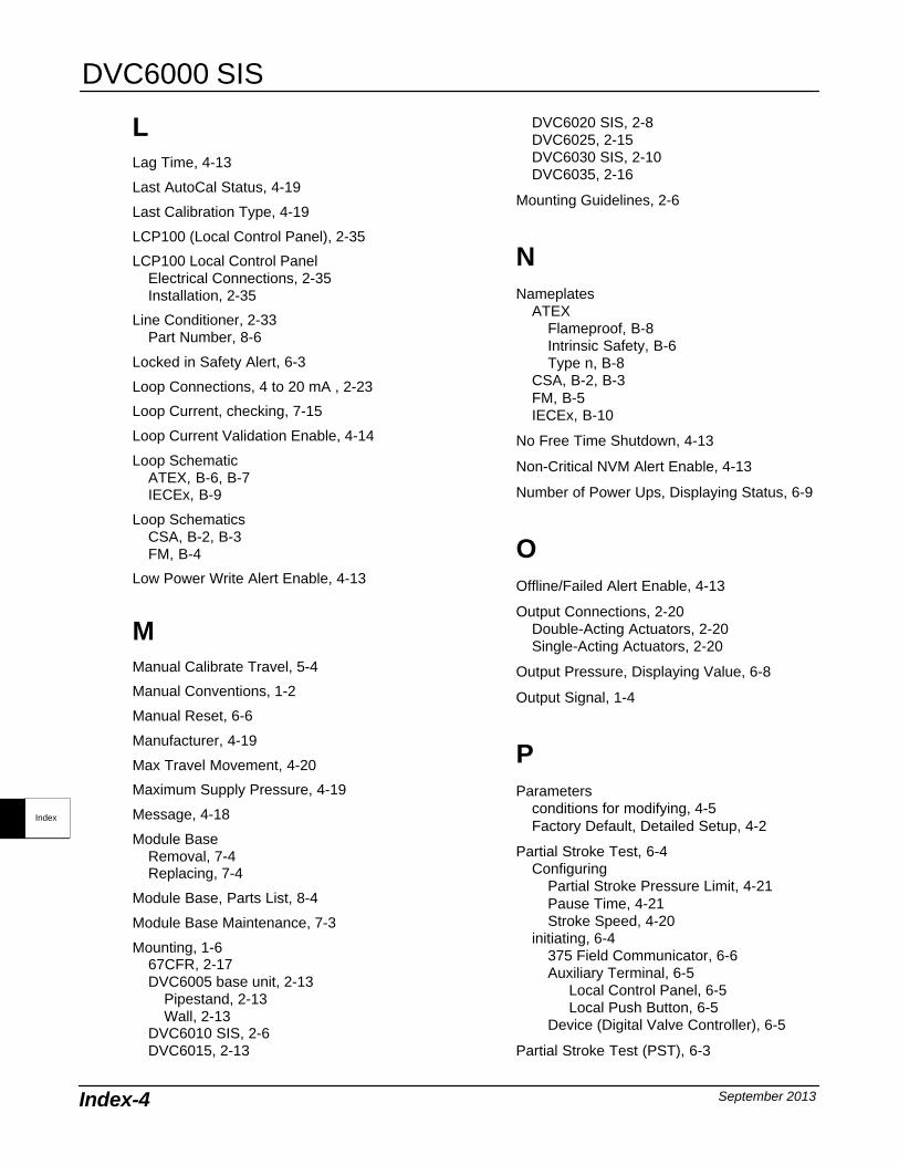
DVC6000 SIS
September 2013Index-4
LLag Time, 4-13
Last AutoCal Status, 4-19
Last Calibration Type, 4-19
LCP100 (Local Control Panel), 2-35
LCP100 Local Control PanelElectrical Connections, 2-35Installation, 2-35
Line Conditioner, 2-33Part Number, 8-6
Locked in Safety Alert, 6-3
Loop Connections, 4 to 20 mA , 2-23
Loop Current, checking, 7-15
Loop Current Validation Enable, 4-14
Loop SchematicATEX, B-6, B-7IECEx, B-9
Loop SchematicsCSA, B-2, B-3FM, B-4
Low Power Write Alert Enable, 4-13
MManual Calibrate Travel, 5-4
Manual Conventions, 1-2
Manual Reset, 6-6
Manufacturer, 4-19
Max Travel Movement, 4-20
Maximum Supply Pressure, 4-19
Message, 4-18
Module BaseRemoval, 7-4Replacing, 7-4
Module Base, Parts List, 8-4
Module Base Maintenance, 7-3
Mounting, 1-667CFR, 2-17DVC6005 base unit, 2-13
Pipestand, 2-13Wall, 2-13
DVC6010 SIS, 2-6DVC6015, 2-13
DVC6020 SIS, 2-8DVC6025, 2-15DVC6030 SIS, 2-10DVC6035, 2-16
Mounting Guidelines, 2-6
NNameplates
ATEXFlameproof, B-8Intrinsic Safety, B-6Type n, B-8
CSA, B-2, B-3FM, B-5IECEx, B-10
No Free Time Shutdown, 4-13
Non-Critical NVM Alert Enable, 4-13
Number of Power Ups, Displaying Status, 6-9
OOffline/Failed Alert Enable, 4-13
Output Connections, 2-20Double-Acting Actuators, 2-20Single-Acting Actuators, 2-20
Output Pressure, Displaying Value, 6-8
Output Signal, 1-4
PParameters
conditions for modifying, 4-5Factory Default, Detailed Setup, 4-2
Partial Stroke Test, 6-4Configuring
Partial Stroke Pressure Limit, 4-21Pause Time, 4-21Stroke Speed, 4-20
initiating, 6-4375 Field Communicator, 6-6Auxiliary Terminal, 6-5
Local Control Panel, 6-5Local Push Button, 6-5
Device (Digital Valve Controller), 6-5
Partial Stroke Test (PST), 6-3
Index
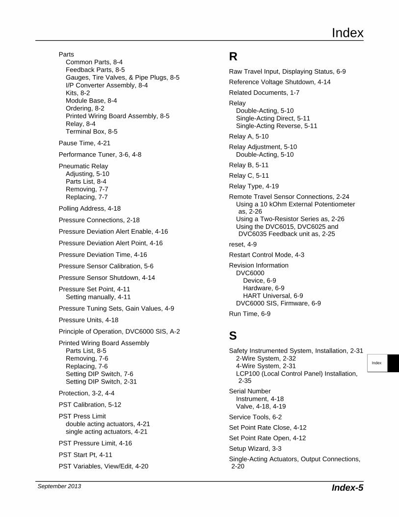
Index
September 2013 Index-5
PartsCommon Parts, 8-4Feedback Parts, 8-5Gauges, Tire Valves, & Pipe Plugs, 8-5I/P Converter Assembly, 8-4Kits, 8-2Module Base, 8-4Ordering, 8-2Printed Wiring Board Assembly, 8-5Relay, 8-4Terminal Box, 8-5
Pause Time, 4-21
Performance Tuner, 3-6, 4-8
Pneumatic RelayAdjusting, 5-10Parts List, 8-4Removing, 7-7Replacing, 7-7
Polling Address, 4-18
Pressure Connections, 2-18
Pressure Deviation Alert Enable, 4-16
Pressure Deviation Alert Point, 4-16
Pressure Deviation Time, 4-16
Pressure Sensor Calibration, 5-6
Pressure Sensor Shutdown, 4-14
Pressure Set Point, 4-11Setting manually, 4-11
Pressure Tuning Sets, Gain Values, 4-9
Pressure Units, 4-18
Principle of Operation, DVC6000 SIS, A-2
Printed Wiring Board AssemblyParts List, 8-5Removing, 7-6Replacing, 7-6Setting DIP Switch, 7-6Setting DIP Switch, 2-31
Protection, 3-2, 4-4
PST Calibration, 5-12
PST Press Limitdouble acting actuators, 4-21single acting actuators, 4-21
PST Pressure Limit, 4-16
PST Start Pt, 4-11
PST Variables, View/Edit, 4-20
RRaw Travel Input, Displaying Status, 6-9
Reference Voltage Shutdown, 4-14
Related Documents, 1-7
RelayDouble-Acting, 5-10Single-Acting Direct, 5-11Single-Acting Reverse, 5-11
Relay A, 5-10
Relay Adjustment, 5-10Double-Acting, 5-10
Relay B, 5-11
Relay C, 5-11
Relay Type, 4-19
Remote Travel Sensor Connections, 2-24Using a 10 kOhm External Potentiometeras, 2-26
Using a Two-Resistor Series as, 2-26Using the DVC6015, DVC6025 andDVC6035 Feedback unit as, 2-25
reset, 4-9
Restart Control Mode, 4-3
Revision InformationDVC6000
Device, 6-9Hardware, 6-9HART Universal, 6-9
DVC6000 SIS, Firmware, 6-9
Run Time, 6-9
SSafety Instrumented System, Installation, 2-31
2-Wire System, 2-324-Wire System, 2-31LCP100 (Local Control Panel) Installation,2-35
Serial NumberInstrument, 4-18Valve, 4-18, 4-19
Service Tools, 6-2
Set Point Rate Close, 4-12
Set Point Rate Open, 4-12
Setup Wizard, 3-3
Single-Acting Actuators, Output Connections,2-20
Index
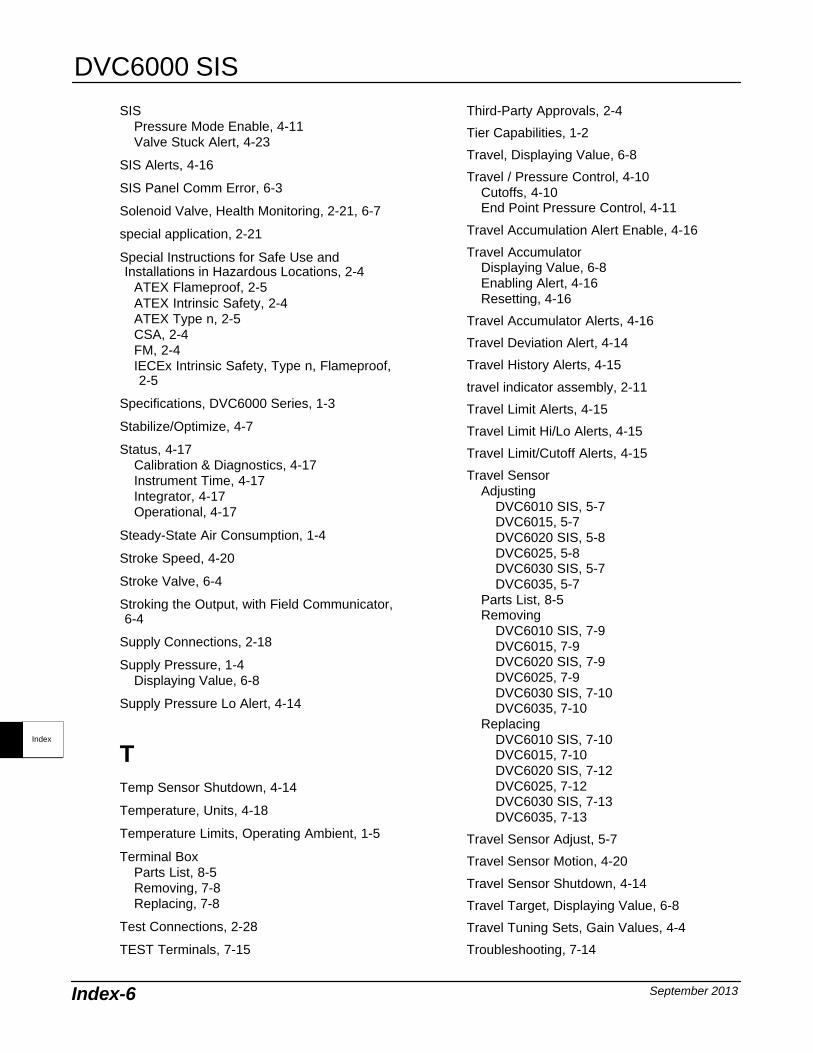
DVC6000 SIS
September 2013Index-6
SISPressure Mode Enable, 4-11Valve Stuck Alert, 4-23
SIS Alerts, 4-16
SIS Panel Comm Error, 6-3
Solenoid Valve, Health Monitoring, 2-21, 6-7
special application, 2-21
Special Instructions for Safe Use andInstallations in Hazardous Locations, 2-4
ATEX Flameproof, 2-5ATEX Intrinsic Safety, 2-4ATEX Type n, 2-5CSA, 2-4FM, 2-4IECEx Intrinsic Safety, Type n, Flameproof,2-5
Specifications, DVC6000 Series, 1-3
Stabilize/Optimize, 4-7
Status, 4-17Calibration & Diagnostics, 4-17Instrument Time, 4-17Integrator, 4-17Operational, 4-17
Steady-State Air Consumption, 1-4
Stroke Speed, 4-20
Stroke Valve, 6-4
Stroking the Output, with Field Communicator,6-4
Supply Connections, 2-18
Supply Pressure, 1-4Displaying Value, 6-8
Supply Pressure Lo Alert, 4-14
TTemp Sensor Shutdown, 4-14
Temperature, Units, 4-18
Temperature Limits, Operating Ambient, 1-5
Terminal BoxParts List, 8-5Removing, 7-8Replacing, 7-8
Test Connections, 2-28
TEST Terminals, 7-15
Third-Party Approvals, 2-4
Tier Capabilities, 1-2
Travel, Displaying Value, 6-8
Travel / Pressure Control, 4-10Cutoffs, 4-10End Point Pressure Control, 4-11
Travel Accumulation Alert Enable, 4-16
Travel AccumulatorDisplaying Value, 6-8Enabling Alert, 4-16Resetting, 4-16
Travel Accumulator Alerts, 4-16
Travel Deviation Alert, 4-14
Travel History Alerts, 4-15
travel indicator assembly, 2-11
Travel Limit Alerts, 4-15
Travel Limit Hi/Lo Alerts, 4-15
Travel Limit/Cutoff Alerts, 4-15
Travel SensorAdjusting
DVC6010 SIS, 5-7DVC6015, 5-7DVC6020 SIS, 5-8DVC6025, 5-8DVC6030 SIS, 5-7DVC6035, 5-7
Parts List, 8-5Removing
DVC6010 SIS, 7-9DVC6015, 7-9DVC6020 SIS, 7-9DVC6025, 7-9DVC6030 SIS, 7-10DVC6035, 7-10
ReplacingDVC6010 SIS, 7-10DVC6015, 7-10DVC6020 SIS, 7-12DVC6025, 7-12DVC6030 SIS, 7-13DVC6035, 7-13
Travel Sensor Adjust, 5-7
Travel Sensor Motion, 4-20
Travel Sensor Shutdown, 4-14
Travel Target, Displaying Value, 6-8
Travel Tuning Sets, Gain Values, 4-4
Troubleshooting, 7-14
Index
Index
September 2013 Index-7
Tuning, 4-4Pressure, 4-9Travel, 4-4
Tuning SetPressure, 4-9Travel, 4-4
Tuning SetsPressure, 4-9
Gain Values, 4-9Travel, 4-4
Gain Values, 4-4
Type 67CFR filter regulator, 2-19
VValve Serial Number, 4-18, 4-19
Valve Style, 4-19
Vent, 2-22
View/Edit Auto Test Interval, 4-22
View/Edit PST Variables, 4-20
Voltage AvailableCalculating, 2-28Checking, 7-14
WWeight, Valve-Mounted Instruments, 1-6
Wiring Length Guidelines, Auxiliary Terminal ,6-5
Wiring PracticesCommunication Cable Capacitance, 2-29Control System Requirements, 2-28
Compliance Voltage, 2-29Voltage Available, 2-28
ZZero Power Condition, 4-19
Index
DVC6000 SIS
September 2013Index-8
Index


Emerson Process ManagementMarshalltown, Iowa 50158 USASorocaba, 18087 BrazilChatham, Kent ME4 4QZ UKDubai, United Arab EmiratesSingapore 128461 Singapore
www.Fisher.com
The contents of this publication are presented for informational purposes only, and while every effort has been made to ensure their accuracy,they are not to be construed as warranties or guarantees, express or implied, regarding the products or services described herein or their use orapplicability. All sales are governed by our terms and conditions, which are available upon request. We reserve the right to modify or improve thedesigns or specifications of such products at any time without notice.
2007, 2013 Fisher Controls International LLC. All rights reserved.
Neither Emerson, Emerson Process Management, nor any of their affiliated entities assumes responsibility for the selection, use ormaintenance of any product. Responsibility for proper selection, use, and maintenance of any product remains solely with thepurchaser and end-user.
Fisher, FIELDVUE, PlantWeb, ValveLink, and THUM are marks owned by one of the companies in the Emerson Process Management businessunit of Emerson Electric Co. Emerson Process Management, Emerson, and the Emerson logo are trademarks and service marks of EmersonElectric Co. ASCO is a mark owned by one of the Emerson Industrial Automation group of companies. All other marks are the property of theirrespective owners.