instruction-level parallelism: tomasulo - reorder buffer
TRANSCRIPT
1
Dr. Tao Xie
These slides are adapted from notes by Dr. David Patterson (UCB)
Instruction-level parallelism: Tomasulo - Reorder Buffer

2
Why can Tomasulo overlap iterations of loops?
• Register renaming – Multiple iterations use different physical destinations for
registers
• Reservation stations – Permit instruction issue to advance past integer control flow
operations – Also buffer old values of registers - totally avoiding the
WAR stall that we saw in the scoreboard.
• Other perspective: Tomasulo building data flow dependency graph on the fly.

3
What about Precise Interrupts? • Interrupts would be imprecise in Tomasulo.
• Tomasulo had:
In-order issue, out-of-order execution, and out-of-order completion
• Need to “fix” the out-of-order completion aspect so that we can find precise breakpoint in instruction stream.

4
Speculating with Tomasulo • Modern processors such as PowerPC 603/604, MIPS
R10000, Intel Pentium II/III/4, Alpha 21264 extend Tomasulo’s approach to support speculation
• Key ideas: – separate execution from completion: allow instructions to
execute speculatively but do not let instructions update registers or memory until they are no longer speculative
– therefore, add a final step – after an instruction is no longer speculative – when it is allowed to make register and memory updates, called instruction commit
– allow instructions to execute and complete out of order but force them to commit in order
– add a hardware buffer, called the reorder buffer (ROB), with registers to hold the result of an instruction between completion and commit
5
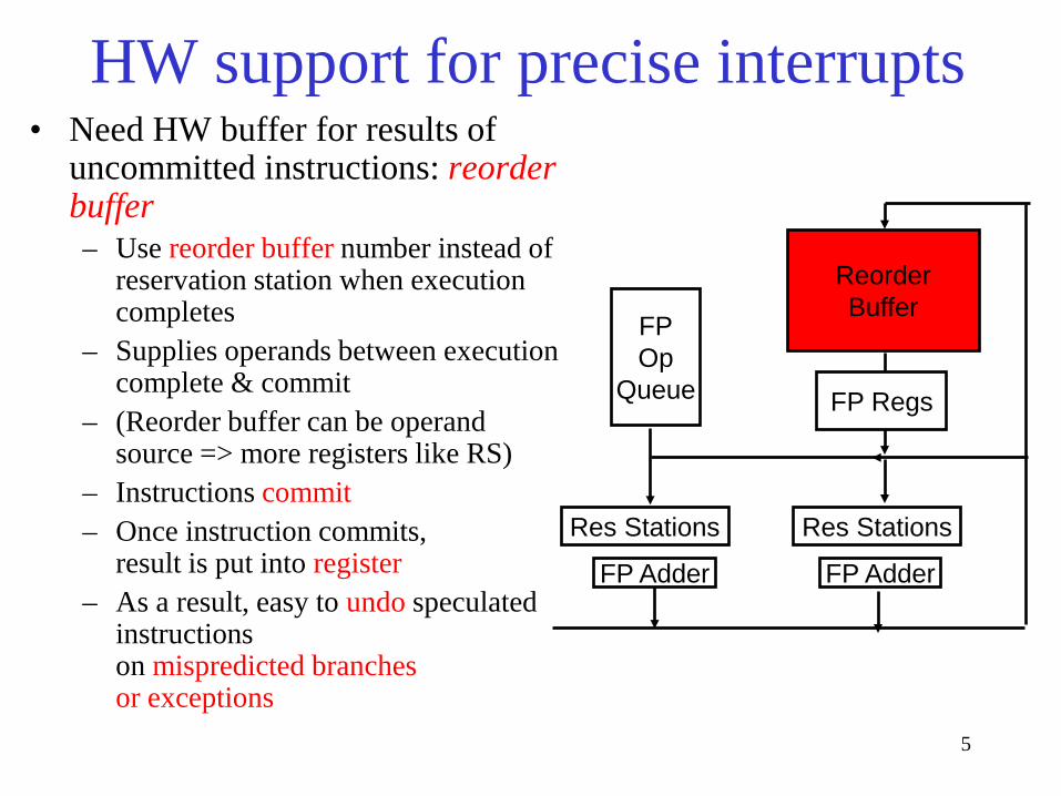
HW support for precise interrupts • Need HW buffer for results of
uncommitted instructions: reorder buffer – Use reorder buffer number instead of
reservation station when execution completes
– Supplies operands between execution complete & commit
– (Reorder buffer can be operand source => more registers like RS)
– Instructions commit – Once instruction commits,
result is put into register – As a result, easy to undo speculated
instructions on mispredicted branches or exceptions
Reorder Buffer
FP Op
Queue
FP Adder FP Adder
Res Stations Res Stations
FP Regs

6
ROB Data Structure ROB entry fields • Instruction type: branch, store, register operation (i.e.,
ALU or load) • State: indicates if instruction has completed and value is
ready • Destination: where result is to be written – register number
for register operation (i.e. ALU or load), memory address for store
– branch has no destination result
• Value: holds the value of instruction result till time to commit
Additional reservation station field • Destination: Corresponding ROB entry number
7
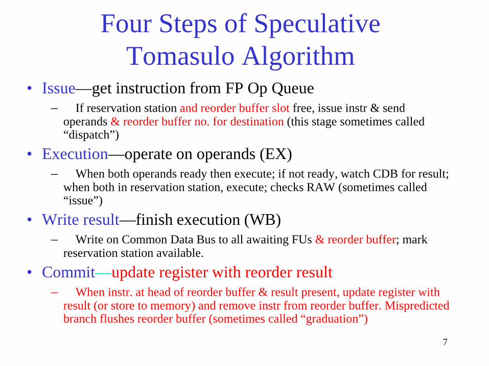
Four Steps of Speculative Tomasulo Algorithm
• Issue—get instruction from FP Op Queue – If reservation station and reorder buffer slot free, issue instr & send
operands & reorder buffer no. for destination (this stage sometimes called “dispatch”)
• Execution—operate on operands (EX) – When both operands ready then execute; if not ready, watch CDB for result;
when both in reservation station, execute; checks RAW (sometimes called “issue”)
• Write result—finish execution (WB) – Write on Common Data Bus to all awaiting FUs & reorder buffer; mark
reservation station available.
• Commit—update register with reorder result – When instr. at head of reorder buffer & result present, update register with
result (or store to memory) and remove instr from reorder buffer. Mispredicted branch flushes reorder buffer (sometimes called “graduation”)

8
Speculative Tomasulo Example
LD F0 10 R2 ADDD F10 F4 F0 DIVD F2 F10 F6 BNEZ F2 Exit
LD F4 0 R3 ADDD F0 F4 F9 SD F4 0 R3 …
Exit:
9
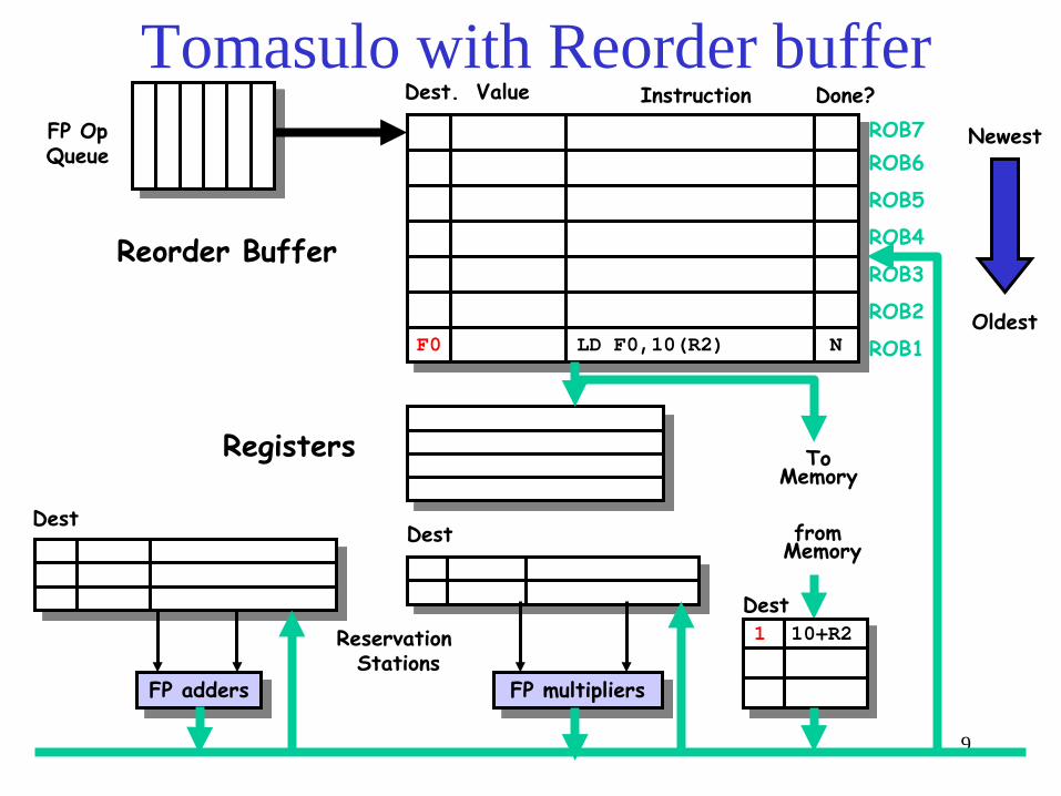
Tomasulo with Reorder buffer
To Memory
FP adders FP multipliers
Reservation Stations
FP Op Queue
ROB7 ROB6
ROB5
ROB4
ROB3
ROB2
ROB1 F0 LD F0,10(R2) N
Done?
Dest Dest
Oldest
Newest
from Memory
1 10+R2 Dest
Reorder Buffer
Registers
Instruction Dest. Value

10
2 ADDD R(F4),ROB1
Tomasulo with Reorder buffer
To Memory
FP adders FP multipliers
Reservation Stations
FP Op Queue
ROB7 ROB6
ROB5
ROB4
ROB3
ROB2
ROB1
F10
F0
ADDD F10,F4,F0
LD F0,10(R2)
N
N
Done?
Dest Dest
Oldest
Newest
from Memory
1 10+R2 Dest
Reorder Buffer
Registers
Instruction Dest. Value

11
3 DIVD ROB2,R(F6) 2 ADDD R(F4),ROB1
Tomasulo with Reorder buffer
To Memory
FP adders FP multipliers
Reservation Stations
FP Op Queue
ROB7 ROB6
ROB5
ROB4
ROB3
ROB2
ROB1
F2
F10
F0
DIVD F2,F10,F6
ADDD F10,F4,F0
LD F0,10(R2)
N
N
N
Done?
Dest Dest
Oldest
Newest
from Memory
1 10+R2 Dest
Reorder Buffer
Registers
Instruction Dest. Value

12
• Skip some cycles

13
3 DIVD ROB2,R(F6) 2 ADDD R(F4),ROB1 6 ADDD ROB5, R(F6)
Tomasulo with Reorder buffer
To Memory
FP adders FP multipliers
Reservation Stations
FP Op Queue
ROB7 ROB6
ROB5
ROB4
ROB3
ROB2
ROB1
F0 ADDD F0,F4,F6 N
F4 LD F4,0(R3) N
-- BNE F2,<…> N
F2
F10
F0
DIVD F2,F10,F6
ADDD F10,F4,F0
LD F0,10(R2)
N
N
N
Done?
Dest Dest
Oldest
Newest
from Memory
1 10+R2 Dest
Reorder Buffer
Registers
5 0+R3
Instruction Dest. Value

14
3 DIVD ROB2,R(F6) 2 ADDD R(F4),ROB1 6 ADDD ROB5, R(F6)
Tomasulo with Reorder buffer
To Memory
FP adders FP multipliers
Reservation Stations
FP Op Queue
ROB7 ROB6
ROB5
ROB4
ROB3
ROB2
ROB1
--
F0
ROB5
SD 0(R3),F4
ADDD F0,F4,F6
N
N
F4 LD F4,0(R3) N
-- BNE F2,<…> N
F2
F10
F0
DIVD F2,F10,F6
ADDD F10,F4,F0
LD F0,10(R2)
N
N
N
Done?
Dest Dest
Oldest
Newest
from Memory
Dest
Reorder Buffer
Registers
1 10+R2 5 0+R3
Instruction Dest. Value
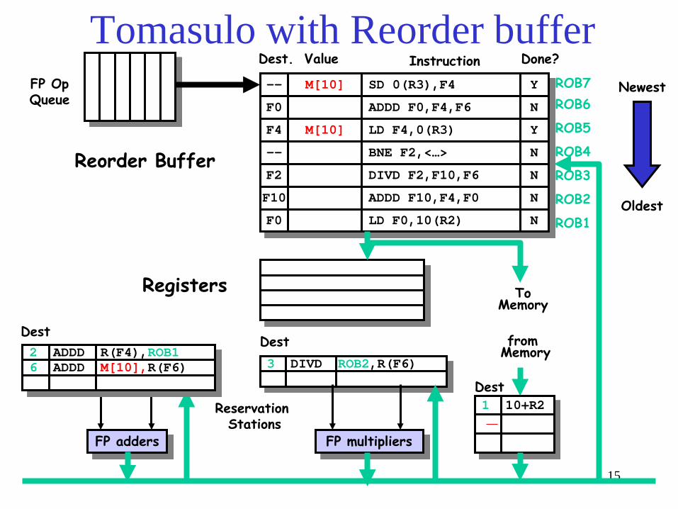
15
3 DIVD ROB2,R(F6)
Tomasulo with Reorder buffer
To Memory
FP adders FP multipliers
Reservation Stations
FP Op Queue
ROB7 ROB6
ROB5
ROB4
ROB3
ROB2
ROB1
--
F0
M[10]
SD 0(R3),F4
ADDD F0,F4,F6
Y
N
F4 M[10] LD F4,0(R3) Y
-- BNE F2,<…> N
F2
F10
F0
DIVD F2,F10,F6
ADDD F10,F4,F0
LD F0,10(R2)
N
N
N
Done?
Dest Dest
Oldest
Newest
from Memory
1 10+R2 Dest
Reorder Buffer
Registers
2 ADDD R(F4),ROB1 6 ADDD M[10],R(F6)
Instruction Dest. Value

16
3 DIVD ROB2,R(F6) 2 ADDD R(F4),ROB1
-
Tomasulo with Reorder buffer
To Memory
FP adders FP multipliers
Reservation Stations
FP Op Queue
ROB7 ROB6
ROB5
ROB4
ROB3
ROB2
ROB1
--
F0
M[10]
---
SD 0(R3),F4
ADDD F0,F4,F6
Y
Ex
F4 M[10] LD F4,0(R3) Y
-- BNE F2,<…> N
F2
F10
F0
DIVD F2,F10,F6
ADDD F10,F4,F0
LD F0,10(R2)
N
N
N
Done?
Dest Dest
Oldest
Newest
from Memory
1 10+R2 Dest
Reorder Buffer
Registers
Instruction Dest. Value

17
Notes • If a branch is mispredicted, recovery is done by
flushing the ROB of all entries that appear after the mispredicted branch – entries before the branch are allowed to continue – restart the fetch at the correct branch successor
• When an instruction commits or is flushed from the ROB then the corresponding slots become available for subsequent instructions

18
Tomasulo Algorithm vs. Scoreboard • Control & buffers distributed with Function Units (FU) vs.
centralized in scoreboard; – FU buffers called “reservation stations”; have pending
operands • Registers in instructions replaced by values or pointers to
reservation stations(RS); called register renaming ; – avoids WAR, WAW hazards – More reservation stations than registers, so can do
optimizations compilers can’t • Results to FU from RS, not through registers, over Common
Data Bus that broadcasts results to all FUs • Load and Stores treated as FUs with RSs as well • Integer instructions can go past branches, allowing
FP ops beyond basic block in FP queue

19
Summary • Reservations stations: implicit register renaming to larger set of
registers + buffering source operands – Prevents registers as bottleneck – Avoids WAR, WAW hazards of Scoreboard – Allows loop unrolling in HW
• Not limited to basic blocks (integer units gets ahead, beyond branches)
• Today, helps cache misses as well – Don’t stall for L1 Data cache miss (insufficient ILP for L2 miss?)
• Lasting Contributions – Dynamic scheduling – Register renaming – Load/store disambiguation
• 360/91 descendants are Pentium III; PowerPC 604; MIPS R10000; HP-PA 8000; Alpha 21264

20
Memory Hierarchy: Introduction

21
Memory Systems - the Big Picture • Memory provides processor with
– Instructions – Data
• Problem: memory is too slow and too small
Control
Datapath
Memory
Processor Input
Output Instructions
Data
“Five Classics Components” Picture

22
DRAM Year Size Cycle Time 1980 64 Kb 250 ns 1983 256 Kb 220 ns 1986 1 Mb 190 ns 1989 4 Mb 165 ns 1992 16 Mb 145 ns 1995 64 Mb 120 ns
Capacity Speed (latency) Logic: 2x in 3 years 2x in 3 years DRAM: 4x in 3 years 2x in 10 years Disk: 4x in 3 years 2x in 10 years
1000:1! 2:1!
Technology Trends
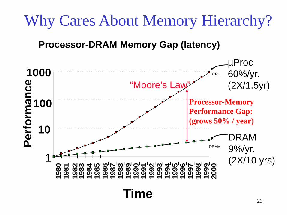
23
µProc 60%/yr. (2X/1.5yr)
DRAM 9%/yr. (2X/10 yrs) 1
10
100
1000 19
80
1981
1983
19
84
1985
19
86
1987
19
88
1989
19
90
1991
19
92
1993
19
94
1995
19
96
1997
19
98
1999
20
00
DRAM
CPU 19
82
Processor-Memory Performance Gap: (grows 50% / year)
Perf
orm
ance
Time
“Moore’s Law”
Processor-DRAM Memory Gap (latency)
Why Cares About Memory Hierarchy?

24
• Rely on caches to bridge gap • Microprocessor-DRAM performance gap
– time of a full cache miss in instructions executed
1st Alpha (7000): 340 ns/5.0 ns = 68 clks x 2 or 136 instructions 2nd Alpha (8400): 266 ns/3.3 ns = 80 clks x 4 or 320 instructions 3rd Alpha (t.b.d.): 180 ns/1.7 ns =108 clks x 6 or 648 instructions
– 1/2X latency x 3X clock rate x 3X Instr/clock ⇒ 5X
Today’s Microprocessor

25
Memory Hierarchy - the Big Picture • Problem: memory is too slow and too small • Solution: memory hierarchy
Control
Datapath
Secondary Storage (Disk)
Processor
Registers
L2 Off-Chip
Cache
Main Memory (DRAM)
L1 O
n-Chip
Cache
0.5-25 5,000,000 (5ms) Speed (ns): 80-250
<1K Size (bytes): >100G <16G <16M
0.25-0.5
26
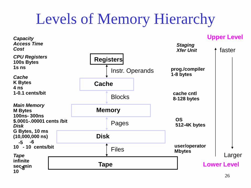
CPU Registers 100s Bytes 1s ns
Cache K Bytes 4 ns 1-0.1 cents/bit
Main Memory M Bytes 100ns- 300ns $.0001-.00001 cents /bit Disk G Bytes, 10 ms (10,000,000 ns) 10 - 10 cents/bit
-5 -6
Capacity Access Time Cost
Tape infinite sec-min 10 -8
Registers
Cache
Memory
Disk
Tape
Instr. Operands
Blocks
Pages
Files
Staging Xfer Unit
prog./compiler 1-8 bytes
cache cntl 8-128 bytes
OS 512-4K bytes
user/operator Mbytes
Upper Level
Lower Level
faster
Larger
Levels of Memory Hierarchy

27
Memory Configuration in Current PCs
Processor
System Controller
L1 Cache
Main Memory (DRAM)
L2/L3 Cache
(SRAM)
(I/O Bus)
• Static RAM (SRAM) - used for L1, L2 cache – Fast - 0.5-25ns access time (less for on-
chip) – Smaller, More Expensive – Higher power consumption
• Dynamic RAM (DRAM) - used for PC main memory – Slower - 80-250ns access time* – Larger, Cheaper – Lower power consumption

28
System Components
SDRAM PC100/PC133 100-133MHz 64-128 bits wide 2-way inteleaved ~ 900 MBYTES/SEC )64bit) Double Date Rate (DDR) SDRAM PC3200 200 MHz DDR 64-128 bits wide 4-way interleaved ~3.2 GBYTES/SEC (64bit) DDR2 SDRAM 667MHZ 8~16 bit wide
CPU
Caches System Bus
I/O Devices
Memory I/O Controllers
Bus Adapter
Disks Displays Keyboards
Networks
NICs
Main I/O Bus Memory Controller Example:
PCI, 33-66MHz 32-64 bits wide 133-528 MB/s PCI-X 133MHz 64-bits wide 1066 MB/s
CPU Core 1 GHz - 3.6 GHz 4-way Superscaler RISC or RISC-core (x86): Deep Instruction Pipelines Dynamic scheduling Multiple FP, integer FUs Dynamic branch prediction Hardware speculation
L1 L2 L3
Memory Bus
All Non-blocking caches L1 16-128K 1-2 way set associative (on chip), separate or unified L2 256K- 2M 4-32 way set associative (on chip) unified L3 2-16M 8-32 way set associative (on or off chip) unified
Examples: Alpha, AMD K7: EV6, 200-400 MHz Intel PII, PIII: GTL+ 133 MHz Intel P4 800 MHz
North Bridge
South Bridge
Chipset
I/O Subsystem
(FSB)
Important issue: Which component creates a system performance bottleneck?
(possibly on-chip)
Chipset

29
Intel Pentium 4 System Architecture (Using The Intel 925 Chipset, 2004)
Source: http://www.anandtech.com/showdoc.aspx?i=2088&p=4
CPU (Including cache) System Bus (Front Side Bus, FSB)
Bandwidth usually should match or exceed that of main memory
I/O Controller Hub (Chipset South Bridge)
System Memory Two 8-byte DDR2 Channels
Main I/O Bus (PCI)
Graphics I/O Bus (PCI Express)
Memory Controller Hub (Chipset North Bridge)
Misc. I/O Interfaces
Misc. I/O Interfaces
Storage I/O (Serial ATA)
I/O Subsystem Current System Architecture: Isolated I/O: Separate memory and I/O buses.

30
• The Principle of Locality: – Program access a relatively small portion of the address
space at any instant of time. • Two Different Types of Locality:
– Temporal Locality (Locality in Time): If an item is referenced, it will tend to be referenced again soon (e.g., loops, reuse)
– Spatial Locality (Locality in Space): If an item is referenced, items whose addresses are close by tend to be referenced soon (e.g., straightline code, array access)
• Last 15 years, HW relied on locality for speed
The Principle of Locality

31
Why Hierarchy Works • The principle of locality
– Programs access a relatively small portion of the address space at any instant of time.
– Temporal locality: recently accessed data is likely to be used again
– Spatial locality: data near recently accessed data is likely to be used soon
• Result: the illusion of large, fast memory
Address Space 0 2n - 1
Probability of reference
32
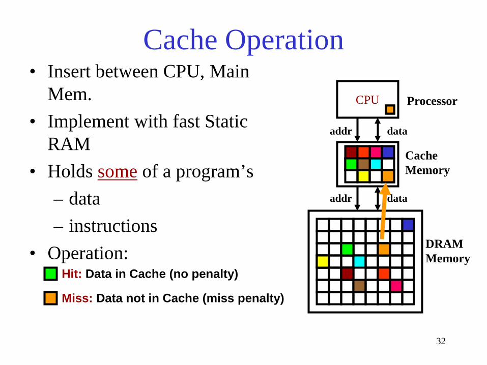
CPU
Hit: Data in Cache (no penalty)
Miss: Data not in Cache (miss penalty)
Cache Memory
DRAM Memory
Processor
addr data
addr data
Cache Operation • Insert between CPU, Main
Mem. • Implement with fast Static
RAM • Holds some of a program’s
– data – instructions
• Operation:

33
Cache Performance Measures • Hit rate: fraction found in the cache
– So high that we usually talk about Miss rate = 1 - Hit Rate • Hit time: time to access the cache • Miss penalty: time to replace a block from lower level,
including time to replace in CPU – access time: time to acccess lower level – transfer time: time to transfer block
• Average memory-access time (AMAT) = Hit time + Miss rate x Miss penalty (ns or clocks)

34
Fundamental Questions • Q1: Where can a block be placed in the upper level? (Block placement) • Q2: How is a block found if it is in the upper level? (Block identification) • Q3: Which block should be replaced on a miss? (Block replacement) • Q4: What happens on a write? (Write strategy)