instruction - campbell scis.campbellsci.com/documents/us/manuals/tdr100.pdf · to obtain a returned...
TRANSCRIPT

INST
RU
CT
ION
MA
NU
AL
TDR100 Revision: 5/15
C o p y r i g h t © 2 0 0 0 - 2 0 1 5 C a m p b e l l S c i e n t i f i c , I n c .


Limited Warranty “Products manufactured by CSI are warranted by CSI to be free from defects in materials and workmanship under normal use and service for twelve months from the date of shipment unless otherwise specified in the corresponding product manual. (Product manuals are available for review online at www.campbellsci.com.) Products not manufactured by CSI, but that are resold by CSI, are warranted only to the limits extended by the original manufacturer. Batteries, fine-wire thermocouples, desiccant, and other consumables have no warranty. CSI’s obligation under this warranty is limited to repairing or replacing (at CSI’s option) defective Products, which shall be the sole and exclusive remedy under this warranty. The Customer assumes all costs of removing, reinstalling, and shipping defective Products to CSI. CSI will return such Products by surface carrier prepaid within the continental United States of America. To all other locations, CSI will return such Products best way CIP (port of entry) per Incoterms ® 2010. This warranty shall not apply to any Products which have been subjected to modification, misuse, neglect, improper service, accidents of nature, or shipping damage. This warranty is in lieu of all other warranties, expressed or implied. The warranty for installation services performed by CSI such as programming to customer specifications, electrical connections to Products manufactured by CSI, and Product specific training, is part of CSI's product warranty. CSI EXPRESSLY DISCLAIMS AND EXCLUDES ANY IMPLIED WARRANTIES OF MERCHANTABILITY OR FITNESS FOR A PARTICULAR PURPOSE. CSI hereby disclaims, to the fullest extent allowed by applicable law, any and all warranties and conditions with respect to the Products, whether express, implied or statutory, other than those expressly provided herein.”

Assistance Products may not be returned without prior authorization. The following contact information is for US and international customers residing in countries served by Campbell Scientific, Inc. directly. Affiliate companies handle repairs for customers within their territories. Please visit www.campbellsci.com to determine which Campbell Scientific company serves your country.
To obtain a Returned Materials Authorization (RMA), contact CAMPBELL SCIENTIFIC, INC., phone (435) 227-9000. After an application engineer determines the nature of the problem, an RMA number will be issued. Please write this number clearly on the outside of the shipping container. Campbell Scientific’s shipping address is:
CAMPBELL SCIENTIFIC, INC. RMA#_____ 815 West 1800 North Logan, Utah 84321-1784
For all returns, the customer must fill out a “Statement of Product Cleanliness and Decontamination” form and comply with the requirements specified in it. The form is available from our web site at www.campbellsci.com/repair. A completed form must be either emailed to [email protected] or faxed to (435) 227-9106. Campbell Scientific is unable to process any returns until we receive this form. If the form is not received within three days of product receipt or is incomplete, the product will be returned to the customer at the customer’s expense. Campbell Scientific reserves the right to refuse service on products that were exposed to contaminants that may cause health or safety concerns for our employees.

Precautions DANGER — MANY HAZARDS ARE ASSOCIATED WITH INSTALLING, USING, MAINTAINING, AND WORKING ON OR AROUND TRIPODS, TOWERS, AND ANY ATTACHMENTS TO TRIPODS AND TOWERS SUCH AS SENSORS, CROSSARMS, ENCLOSURES, ANTENNAS, ETC. FAILURE TO PROPERLY AND COMPLETELY ASSEMBLE, INSTALL, OPERATE, USE, AND MAINTAIN TRIPODS, TOWERS, AND ATTACHMENTS, AND FAILURE TO HEED WARNINGS, INCREASES THE RISK OF DEATH, ACCIDENT, SERIOUS INJURY, PROPERTY DAMAGE, AND PRODUCT FAILURE. TAKE ALL REASONABLE PRECAUTIONS TO AVOID THESE HAZARDS. CHECK WITH YOUR ORGANIZATION'S SAFETY COORDINATOR (OR POLICY) FOR PROCEDURES AND REQUIRED PROTECTIVE EQUIPMENT PRIOR TO PERFORMING ANY WORK.
Use tripods, towers, and attachments to tripods and towers only for purposes for which they are designed. Do not exceed design limits. Be familiar and comply with all instructions provided in product manuals. Manuals are available at www.campbellsci.com or by telephoning (435) 227-9000 (USA). You are responsible for conformance with governing codes and regulations, including safety regulations, and the integrity and location of structures or land to which towers, tripods, and any attachments are attached. Installation sites should be evaluated and approved by a qualified engineer. If questions or concerns arise regarding installation, use, or maintenance of tripods, towers, attachments, or electrical connections, consult with a licensed and qualified engineer or electrician. General
• Prior to performing site or installation work, obtain required approvals and permits. Comply with all governing structure-height regulations, such as those of the FAA in the USA.
• Use only qualified personnel for installation, use, and maintenance of tripods and towers, and any attachments to tripods and towers. The use of licensed and qualified contractors is highly recommended.
• Read all applicable instructions carefully and understand procedures thoroughly before beginning work.
• Wear a hardhat and eye protection, and take other appropriate safety precautions while working on or around tripods and towers.
• Do not climb tripods or towers at any time, and prohibit climbing by other persons. Take reasonable precautions to secure tripod and tower sites from trespassers.
• Use only manufacturer recommended parts, materials, and tools.
Utility and Electrical • You can be killed or sustain serious bodily injury if the tripod, tower, or attachments you are
installing, constructing, using, or maintaining, or a tool, stake, or anchor, come in contact with overhead or underground utility lines.
• Maintain a distance of at least one-and-one-half times structure height, 20 feet, or the distance required by applicable law, whichever is greater, between overhead utility lines and the structure (tripod, tower, attachments, or tools).
• Prior to performing site or installation work, inform all utility companies and have all underground utilities marked.
• Comply with all electrical codes. Electrical equipment and related grounding devices should be installed by a licensed and qualified electrician.
Elevated Work and Weather • Exercise extreme caution when performing elevated work. • Use appropriate equipment and safety practices. • During installation and maintenance, keep tower and tripod sites clear of un-trained or non-
essential personnel. Take precautions to prevent elevated tools and objects from dropping. • Do not perform any work in inclement weather, including wind, rain, snow, lightning, etc.
Maintenance • Periodically (at least yearly) check for wear and damage, including corrosion, stress cracks,
frayed cables, loose cable clamps, cable tightness, etc. and take necessary corrective actions. • Periodically (at least yearly) check electrical ground connections.
WHILE EVERY ATTEMPT IS MADE TO EMBODY THE HIGHEST DEGREE OF SAFETY IN ALL CAMPBELL SCIENTIFIC PRODUCTS, THE CUSTOMER ASSUMES ALL RISK FROM ANY INJURY RESULTING FROM IMPROPER INSTALLATION, USE, OR MAINTENANCE OF TRIPODS, TOWERS, OR ATTACHMENTS TO TRIPODS AND TOWERS SUCH AS SENSORS, CROSSARMS, ENCLOSURES, ANTENNAS, ETC.


i
Table of Contents PDF viewers: These page numbers refer to the printed version of this document. Use the PDF reader bookmarks tab for links to specific sections.
1. Introduction ................................................................. 1
2. Cautionary Statements ............................................... 1
3. Initial Inspection ......................................................... 1
3.1 TDR100 Packing List ........................................................................... 2 3.2 SDM8X50 Packing List ....................................................................... 2 3.3 ENCTDR100 Packing List ................................................................... 2
4. Quickstart .................................................................... 2
4.1 Getting Started with TDR100 using PC-TDR ...................................... 2 4.2 Discussion of Distances and Propagation Velocity (Vp) when
using TDR100 .................................................................................. 3 4.3 More Information ................................................................................. 5
5. Overview ...................................................................... 5
6. System Specifications ................................................ 6
6.1 TDR100 Performance .......................................................................... 6 6.2 Electromagnetic Compatibility ............................................................ 7 6.3 SDM8X50 Major Specifications .......................................................... 7
6.3.1 Physical ......................................................................................... 7 6.3.2 Electrical ....................................................................................... 8
7. Installation ................................................................... 8
7.1 PC-TDR Software ................................................................................ 8 7.1.1 PC-TDR Help ............................................................................... 9 7.1.2 Menu Selections ............................................................................ 9
7.1.2.1 File Menu ........................................................................... 9 7.1.2.2 Settings Menu ..................................................................... 9 7.1.2.3 Options Menu ..................................................................... 9
7.1.3 PC-TDR Parameter Selection Boxes .......................................... 10 7.1.3.1 Cable ................................................................................ 10 7.1.3.2 Waveform ......................................................................... 10 7.1.3.3 A Discussion of Start and Length Parameters .................. 11
7.2 System Components: Datalogger Control ......................................... 12 7.2.1 General ........................................................................................ 12 7.2.2 Datalogger ................................................................................... 13 7.2.3 TDR100 ...................................................................................... 13 7.2.4 SDM8X50 ................................................................................... 13 7.2.5 Power Supply .............................................................................. 13
7.2.5.1 Grounding ........................................................................ 14 7.2.6 SDM Communication ................................................................. 14
7.2.6.1 SDM Addressing for TDR100 System ............................. 14

Table of Contents
ii
7.2.6.2 SDM Cable and Cable Length Considerations ................ 15 7.2.7 ENCTDR100 .............................................................................. 15
7.2.7.1 Mounting Equipment in ENCTDR100 ............................ 15 7.2.8 Soil Probes ................................................................................. 16
7.2.8.1 Determining Probe Constant, Kp, using PC-TDR ............ 17 7.3 Datalogger Programming .................................................................. 17
7.3.1 TDR100() CRBasic Instruction .................................................. 17
8. Operation ................................................................... 19
8.1 TDR Principles .................................................................................. 19 8.2 Cable Length and Soil Electrical Conductivity Effect on Water
Content Determination ................................................................... 21 8.2.1 Cable Length Effect on Water Content Measurement ................ 21 8.2.2 Soil Electrical Conductivity Effect on Water Content
Measurement .......................................................................... 22 8.3 Algorithm Description and Parameter Adjustment ........................... 23
8.3.1 Algorithm for Calculation of TDR Probe Rod Apparent Length ..................................................................................... 23
8.3.1.1 Waveform Evaluation ...................................................... 23 8.3.2 Algorithm Parameter Adjustment for Special Conditions .......... 24
8.3.2.1 Terminal Emulator Commands for Apparent Length Algorithm ..................................................................... 24
8.3.3 Algorithm for Calculation of Bulk Electrical Conductivity ....... 25 8.3.3.1 Algorithm Description ..................................................... 25 8.3.3.2 Algorithm Parameter Adjustment for Special
Conditions .................................................................... 26
9. References ................................................................. 27
Appendices
A. SDMX50-Series Multiplexers .................................. A-1
A.1 General ............................................................................................ A-1 A.2 Specifications .................................................................................. A-1
A.2.1 Physical .................................................................................... A-1 A.2.2 Electrical .................................................................................. A-2
A.3 Signal Attenuation ........................................................................... A-2 A.4 SDM Communication ..................................................................... A-3
A.4.1 SDM Addressing for TDR100 System ..................................... A-3
B. Example Program .................................................... B-1
B.1 CR1000 Program Example .............................................................. B-1
Figures 4-1. Waveform of a CS610 in water ........................................................... 4 4-2. Waveform of CS610 in water after changing Start and Length
parameters to display relevant portion of reflected signal ............... 5 7-1. PC-TDR waveform for CS610 in water. ........................................... 11 7-2. TDR system components ................................................................... 12 7-3. Terminal strip adapters for connections to battery ............................ 13 7-4. ENCTDR100 with SDM8X50, PS150, TDR100, and CR1000 ........ 16

Table of Contents
iii
8-1. Waveforms collected in a sandy loam using CS610 probe with RG8 connecting cable. Volumetric water content is 24% and bulk electrical conductivity is 0.3 dS m–1. ...................................... 21
8-2. Waveforms collected in a sandy loam using CS610 probe with RG8 connecting cable. Volumetric water content values are 10, 16, 18, 21 and 25%. Solution electrical conductivity is 1.0 dS m–1. ............................................................................................ 22
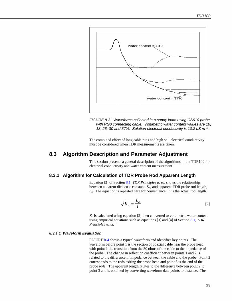
8-3. Waveforms collected in a sandy loam using CS610 probe with RG8 connecting cable. Volumetric water content values are 10, 18, 26, 30 and 37%. Solution electrical conductivity is 10.2 dS m–1. ............................................................................................ 23
8-4. Typical TDR100 waveform showing key features with numbers 1, 2 and 3. ........................................................................................... 24
8-5. PC-TDR terminal emulator screen showing TDR100 algorithm parameter variables. ........................................................................ 25
8-6. Waveform and derivative values near TDR probe and locations of index for point of maximum derivative and maximum derivative value. The green band represents the results of the search using the threshold value. ......................................................................... 27
A-1. SDMX50 signal attenuation ............................................................ A-3 A-2. Location of address jumpers on SDMX50 ...................................... A-4
Tables 7-1. Recommended Waveform Length Values for Range of TDR
Probe Rod Lengths Assuming Soil Porosity of 0.60 ...................... 12

Table of Contents
iv

1
TDR100 1. Introduction
This document presents operating instructions for the TDR100 and associated equipment and discusses time domain reflectometry (TDR) principles. Section 4.1, Getting Started with TDR100 using PC-TDR (p. 2), describes a simple start-up configuration to quickly and easily display TDR probe waveforms using PC-TDR. See the TDR Probes CS605, CS610, CS630, CS635, CS640, CS645 manual for detailed information about TDR probes available from Campbell Scientific. Manuals referenced may be downloaded from our website: www.campbellsci.com/manuals.
The TDR100 Time-Domain Reflectometer is the core of the Campbell Scientific time-domain reflectometry system. This system is used to accurately determine soil volumetric water content, soil bulk electrical conductivity, rock mass deformation, cable testing, and other user-specific time-domain measurements. The TDR100 generates a short rise time electromagnetic pulse that is applied to a coaxial system and samples and digitizes the resulting reflection waveform for analysis or storage.
This manual provides information only for CRBasic dataloggers. It is also compatible with most of our retired Edlog dataloggers. For Edlog datalogger support, see an older manual at www.campbellsci.com/old-manuals or contact a Campbell Scientific application engineer for assistance.
2. Cautionary Statements • READ AND UNDERSTAND the Precautions section at the front of this
manual.
• WARNING: Because the TDR100 is sensitive to electrostatic discharge damage, avoid touching the inner part of the panel BNC connector or the center rod of TDR probes connected to the TDR100.
• Although the TDR100 reflectometer, SMD8X50 multiplexers, and TDR probes are rugged, they should be handled as precision scientific instruments.
3. Initial Inspection • Upon receipt of the equipment, inspect the packaging and contents for
damage. File damage claims with the shipping company.
• Check the contents of the shipment (see Section 3.1, TDR100 Packing List (p. 2), Section 3.2, SDM8X50 Packing List (p. 2), and Section 3.3, ENCTDR100 Packing List (p. 2)). If there is a shortage, contact Campbell Scientific.
NOTE

TDR100
2
3.1 TDR100 Packing List The following are included with a TDR100.
1. TDR100 Time Domain Reflectometer 2. PC-TDR software and instruction manual on Resource DVD 3. A 6 foot long, 9-conductor cable for connection between the serial port of
a computer and the RS-232 port of the TDR100 4. Short 5-conductor cables for SDM connection between (a) datalogger and
TDR100 and between (b) TDR100 and an SDMX50 or SDM8X50 coaxial multiplexer
3.2 SDM8X50 Packing List The following are included with the SDM8X50.
1. SDM8X50 8 channel 50 Ohm coaxial multiplexer 2. 8 #6-32 x .375 pan Philips screws 3. 8 grommets for #6 or #8 screws 4. 20 4-inch nylon cable ties 5. A strain relief bracket with 12 cable tie mounts
When purchased with the –E option, the following items will also be included.
1. ENC10/12 enclosure with mounting hardware 2. Enclosure supply kit
3.3 ENCTDR100 Packing List The following are included with an ENCTDR100.
1. Enclosure Supply Kit; desiccant packs, humidity indicator, cable ties, putty and mounting hardware
2. ENCTDR100 Enclosure Ground Wire Kit 3. TDR100/SDM8X50 Coaxial Interconnect Cable 4. TDR100/SDM8X50 and TDR100/Datalogger SDM 5-Conductor Cable 5. Enclosure ENC16/18 with two 1.7 inch diameter cable penetration ports 6. Terminals for external deep cycle battery
4. Quickstart 4.1 Getting Started with TDR100 using PC-TDR
This section lists steps for a simple connection between a computer and the TDR100 to monitor a single TDR probe using PC-TDR software. A single probe is connected directly to the TDR100, and no multiplexers are used. TDR100 operation with SDM8X50 multiplexers is described in Section 7.2.4, SDM8X50 (p. 13).
1. Install PC-TDR The following instructions assume that drive D: is a CD-ROM drive. If the drive letter is different, substitute the appropriate drive letter.
• Put the installation disk in the CD-ROM drive. The install application should come up automatically. If the install does not start, use Start |

TDR100
3
Run of the Windows system and type D:/Disk1/Setup.exe or use the Browse button to access the CD-ROM drive and select the setup executable file in the Disk1 folder.
• The PC-TDR Installation Utility is activated. Follow the prompts to complete the installation.
• If the installation disk is not available, PC-TDR may be downloaded free of charge at www.campbellsci.com/downloads.
2. Use the supplied 9-conductor cable to connect a computer to the RS-232 connector on the TDR100 The RS-232 connector on the TDR100 is used for communication between a serial communication port of a computer and the TDR100. A 9-conductor cable is supplied with the TDR100. Serial communication port 1 is the default setting and can be changed in PC-TDR menu Settings/Communications. The baud rate is factory set to 57600.
3. Connect 12 volt power to TDR100 12 volt power to the TDR100 is connected using terminals +12V and ground on the panel 5-terminal connector. An external power supply or the 12V terminals of a datalogger can be used for power. The C1, C2 and C3 terminals are for SDM (synchronous device for measurement communication protocol) communications. The C1, C2, and C3 terminals are not used for single probe monitoring with a computer using PC-TDR.
4. Connect a TDR probe to the BNC connector of the TDR100.
5. Start PC-TDR by selecting PC-TDR under Programs of the Windows Start Menu or double-clicking the PC-TDR icon.
6. View a waveform using Get Waveform In the Waveform section of PC-TDR, set Start to 0 or 1 m and Length to the apparent length of the attached probe cable plus 5 meters. Press Get Waveform.
4.2 Discussion of Distances and Propagation Velocity (Vp) when using TDR100
A TDR system is typically comprised of components with different signal propagation properties. The Vp for a particular component depends on transmission line characteristics such as the dielectric constant of inter-conductor insulating material. Setting Vp = 1.0 and using apparent distances simplifies system setup. The displayed position of a waveform is apparent distance. The value chosen for Vp does not affect water content or electrical conductivity measurement. The selected Vp value does affect waveform display.
The relationship between real and apparent distance is given as
apparent distance = (actual distance) x (selected Vp/actual Vp).

TDR100
4
For example, if the actual length of a cable having a Vp of 0.78 is 5 m and the selected Vp is 1.0, the apparent distance to the end of the cable is 5 x (1.0/0.78) = 6.41 m. Typical cable Vp’s range from 0.67 to 0.9. Campbell Scientific TDR probes use RG-58 with a Vp of 0.80, RG-8 with a Vp of 0.84, and LMR200 with a Vp of 0.83.
An example is presented in FIGURE 4-1. Displayed is the waveform for a CS610 in water. The actual cable length is about 5 m. The apparent cable length is about 6 m.
FIGURE 4-1. Waveform of a CS610 in water
Changing the Waveform Start value to 5.7 m and the Waveform Length to 5 m gives the waveform displayed in FIGURE 4-2.

TDR100
5
FIGURE 4-2. Waveform of CS610 in water after changing Start and Length parameters to display relevant portion of reflected signal
4.3 More Information Information on PC-TDR is available from the HELP menu or by pressing F1. Using F1 gives specific help associated with the position of the cursor or active screen. See Section 7.1.1, PC-TDR Help (p. 9), for PC-TDR HELP details.
5. Overview The TDR100 has a single BNC connector for communication with an attached coaxial cable. To measure multiple sensors the TDR100 requires one or more SDM8X50 or SDMX50 multiplexers. The SDM8X50 is a 50 ohm, coaxial, 8:1 multiplexer. It consists of a surge-protected multiplexer circuit board enclosed in a metal housing and a separate strain-relief bracket for the coaxial cables. Both the multiplexer housing and strain relief bracket have holes drilled at a 1-inch spacing. This allows the SDM8X50 to be mounted to a wall or attached to the backplate of a user-supplied enclosure or Campbell Scientific enclosure. When purchased with the –E option, a 10-inch-by-12-inch-by-4.5-inch environmental enclosure and enclosure supply kit are included. Other compatible Campbell Scientific enclosures that may be purchased separately include the ENCTDR100, ENC12/14, ENC14/16, and ENC16/18.
The TDR100 is controlled by a computer using Windows software PC-TDR or by a compatible Campbell Scientific datalogger. Current compatible dataloggers include the CR6, CR800 series, CR1000, and CR3000 and use the TDR100() CRBasic instruction. PC-TDR is used to display waveform information, determine parameters to be used in the datalogger program, and perform basic troubleshooting. PC-TDR does not support automated measurements at prescribed time intervals. For automated measurements, a
TDR100
6
complete TDR system that includes a compatible datalogger, TDR100, SDMX50 series or SDM8X50 multiplexers, 12 V power supply, weatherproof enclosure, and solar panel is recommended.
A single TDR probe can be connected directly to the TDR100 or multiple probes connected via coaxial multiplexer units (SDMX50 series and SDM8X50).
For field applications, the ENCTDR100 enclosure is recommended. The ENCTDR100 is a white, fiberglass reinforced enclosure that protects the TDR100 and other system components from weather, condensing humidity, and dust.
6. System Specifications See the CR6, CR800/CR850, CR1000, or CR3000 datalogger manuals for datalogger specifications.
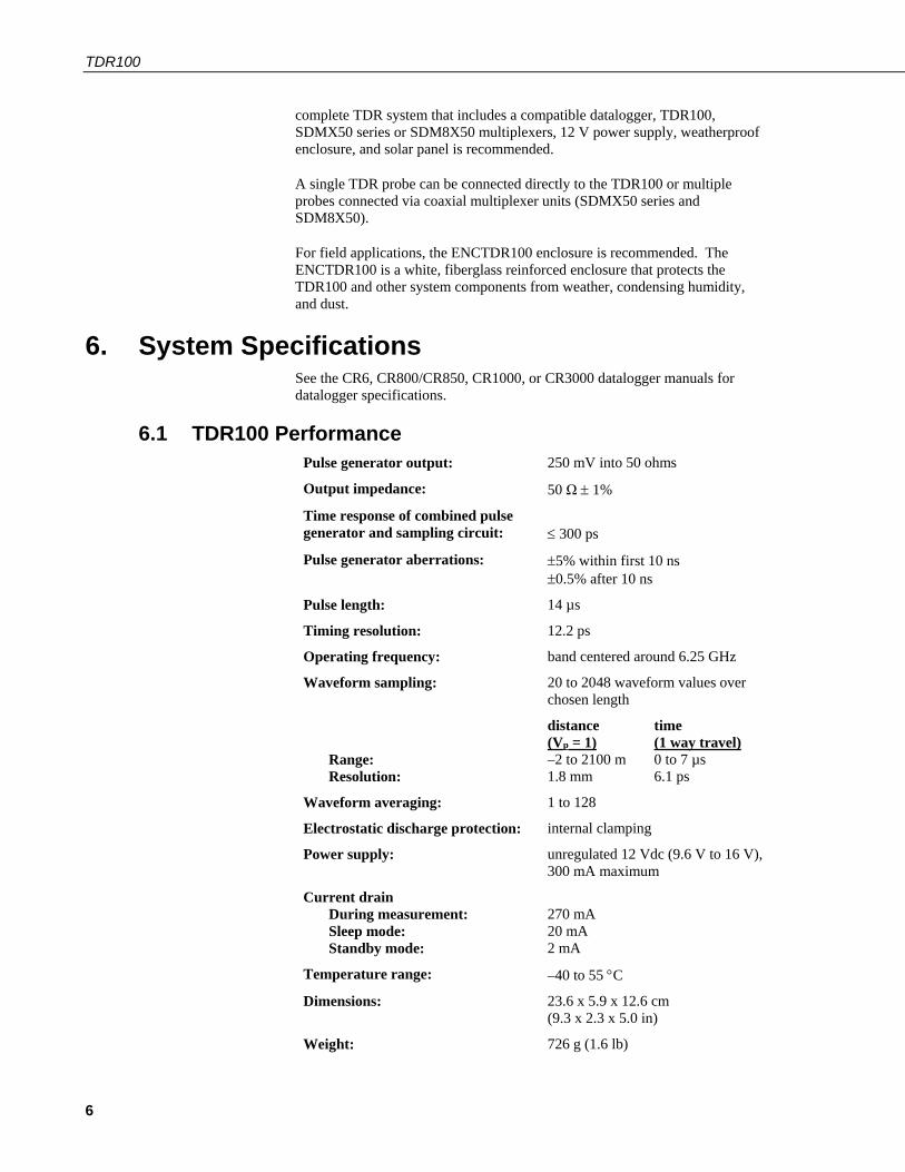
6.1 TDR100 Performance Pulse generator output: 250 mV into 50 ohms
Output impedance: 50 Ω ± 1%
Time response of combined pulse generator and sampling circuit:
≤ 300 ps
Pulse generator aberrations: ±5% within first 10 ns ±0.5% after 10 ns
Pulse length: 14 µs
Timing resolution: 12.2 ps
Operating frequency: band centered around 6.25 GHz
Waveform sampling: 20 to 2048 waveform values over chosen length
Range: Resolution:
distance time (Vp = 1) (1 way travel) –2 to 2100 m 0 to 7 µs 1.8 mm 6.1 ps
Waveform averaging: 1 to 128
Electrostatic discharge protection: internal clamping
Power supply: unregulated 12 Vdc (9.6 V to 16 V), 300 mA maximum
Current drain During measurement: Sleep mode: Standby mode:
270 mA 20 mA 2 mA
Temperature range: –40 to 55 °C
Dimensions: 23.6 x 5.9 x 12.6 cm (9.3 x 2.3 x 5.0 in)
Weight: 726 g (1.6 lb)

TDR100
7
6.2 Electromagnetic Compatibility The TDR100 is Πcompliant with performance criteria available upon request. RF emissions are below EN55022 limit. The TDR100 meets EN61326 requirements for protection against electrostatic discharge and surge except for electrostatic discharge on the center conductor of the panel BNC connector.
The TDR100 is sensitive to electrostatic discharge damage. Avoid touching the center conductor of the panel BNC connector or the center rod of TDR probes connected to the TDR100.
6.3 SDM8X50 Major Specifications 6.3.1 Physical
Consists of Size When Used
SDM8X50 50 Ohm Coaxial Multiplexer
Multiplexer circuit board encased in metal housing and a separate strain relief bracket. Both the circuit board and bracket include mounting holes and hardware for attaching them to the backplate of an enclosure (typically the ENCTDR100) or to a wall.
Weight: 590 g (1.3 lb) Multiplexer Housing Dimensions with Mounts: 24.9 x 12.2 x 4.6 cm (9.8 x 4.8 x 1.8 in) Strain Relief Bracket Dimensions: 20.3 x 4.3 x 1.3 cm (8.0 x 1.7 x 0.5 in)
When the multiplexer will be housed in the same enclosure as the datalogger and power supply or when the multiplexer will reside in a building
SDM8X50-E SDM8X50 multiplexer with an ENC10/12 environmental enclosure. Enclosure includes a bracket for mounting to a tripod, tower, or a 1.0 in. to 1.25 in. IPS Schedule 40 pipe.
Weight: 4.4 kg (9.8 lb) Enclosure Outside Dimensions with Mounts: 40.4 x 29.2 x 17.5 cm (15.9 x 11.5 x 6.9 in) Enclosure Inside Dimensions: 25.4 x 30.4 x 12.7 cm (10 x 12 x 5 in)
When the multiplexer will be housed in its own enclosure without the datalogger and power supply
Temperature range: –40 to 55 °C
Warning

TDR100
8
6.3.2 Electrical Input power: 12 Vdc
Quiescent current drain: < 1 mA
Current drain during switching: ~90 mA (all multiplexers of the same level switch simultaneously for less than 1 s. See FIGURE 7-2.)
Relay contact life expectancy: 100 x 106 operations
7. Installation 7.1 PC-TDR Software
A display for viewing waveforms is generally needed only for system setup and troubleshooting, and the TDR100 does not have a built-in display. Windows software PC-TDR is used with a personal computer to configure the TDR100 and multiplexers and display waveforms.
Conflicts between commands simultaneously issued by a datalogger and PC-TDR will cause error messages in PC-TDR. To prevent these errors, halt the datalogger program while controlling the TDR100 with PC-TDR. Halting the program can be accomplished by navigating to File Control | Stop Program for CRBasic dataloggers. Be sure to restart the datalogger program after using PC-TDR.
When the TDR100 is connected to a CR1000 datalogger using control ports 1 through 3 for SDM control and SDM8X50 or SDMX50 multiplexers are also connected, an instruction must be used in the datalogger program to properly configure the control ports. If this is not done, PC-TDR will not control the multiplexers. This is required because the CR1000 control ports present a low impedance to the SDM lines and this will load the signal issued by TDR100 when PC-TDR is used to control multiplexers.
At the end of the CR1000 datalogger program containing TDR100 instruction (TDR100), use the PortsConfig() CRBasic instruction to configure control ports 1, 2, and 3 as input.
PortsConfig (&B00000111,&B00000000)
PC-TDR requires a connection from a COM port of the computer to the RS-232 port of the TDR100. Choice of COM port and baud rate is made in PC-TDR menu Settings/Communications. The baud rate is set during TDR100 production to 57600. If the computer does not have a 9-pin serial COM port, then a USB to serial converter cable may be used.
NOTE
Note for use of PCTDR when TDR100 is
connected to CR1000 datalogger
TDR100
9
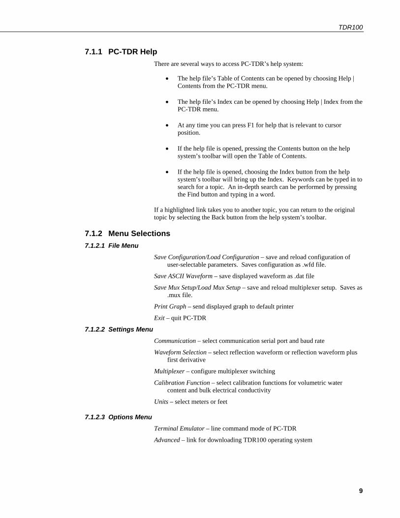
7.1.1 PC-TDR Help There are several ways to access PC-TDR’s help system:
• The help file’s Table of Contents can be opened by choosing Help | Contents from the PC-TDR menu.
• The help file’s Index can be opened by choosing Help | Index from the PC-TDR menu.
• At any time you can press F1 for help that is relevant to cursor position.
• If the help file is opened, pressing the Contents button on the help system’s toolbar will open the Table of Contents.
• If the help file is opened, choosing the Index button from the help system’s toolbar will bring up the Index. Keywords can be typed in to search for a topic. An in-depth search can be performed by pressing the Find button and typing in a word.
If a highlighted link takes you to another topic, you can return to the original topic by selecting the Back button from the help system’s toolbar.
7.1.2 Menu Selections 7.1.2.1 File Menu
Save Configuration/Load Configuration – save and reload configuration of user-selectable parameters. Saves configuration as .wfd file.
Save ASCII Waveform – save displayed waveform as .dat file
Save Mux Setup/Load Mux Setup – save and reload multiplexer setup. Saves as .mux file.
Print Graph – send displayed graph to default printer
Exit – quit PC-TDR
7.1.2.2 Settings Menu Communication – select communication serial port and baud rate
Waveform Selection – select reflection waveform or reflection waveform plus first derivative
Multiplexer – configure multiplexer switching
Calibration Function – select calibration functions for volumetric water content and bulk electrical conductivity
Units – select meters or feet
7.1.2.3 Options Menu Terminal Emulator – line command mode of PC-TDR
Advanced – link for downloading TDR100 operating system

TDR100
10
7.1.3 PC-TDR Parameter Selection Boxes 7.1.3.1 Cable
The cable propagation velocity, Vp, depends on the dielectric constant of the insulating material between the coaxial cable center conductor and outer shield. The value entered in this parameter selection box is the ratio of the actual propagation velocity for a selected medium to the propagation velocity in a vacuum (3 x 10⁸ m s–1). Specific Vp values for each coaxial cable are available from manufacturer data books. It is only necessary to know the Vp value if the TDR100 is used as a cable tester for finding cable lengths or faults.
See Section 4.2, Discussion of Distances and Propagation Velocity (Vp) when using TDR100 (p. 3), for a discussion of propagation velocity.
Calculation of water content or electrical conductivity is independent of the chosen value for Vp because Vp cancels in the calculation. However the Vp value does affect waveform display.
For water content measurements, it is recommended that propagation velocity, Vp, be set at 1.0.
7.1.3.2 Waveform Average – sets the number of measurements averaged at a given distance from the TDR100. A value of 4 is recommended. Higher values can be used when noise is present. Averaging is useful when noise from power sources or when noise of random nature is superimposed on the reflection waveform. Averaging is accomplished by collecting n values at a given distance before collecting values at the next distance increment where n is the value entered in Average.
Points – the number of points in the displayed or collected waveform (using File/Save ASCII Waveform). For water content measurements, a value of 251 is recommended and will provide 250 waveform increments. A higher value can provide better resolution when collecting waveforms.
Start – the apparent distance from the TDR100 to where the displayed waveform will begin (using File/Save ASCII Waveform). For water content measurements this value should be the apparent distance from the TDR100 to the beginning of the probe minus approximately 0.5 meter. FIGURE 4-2 is an example of the display when the correct start is chosen.
The apparent distance is the (actual distance) x (selected Vp/actual Vp). For example, if the actual length of a cable having a Vp of 0.78 is 5 meters and the selected Vp is 1.0, the apparent distance to the end of the cable is 5 x (1.0/0.78) = 6.41 meters.
Length – Beginning at distance Start, the length of the display window and apparent length depicted by the number of data Points selected. For water content measurements with the CS605 or CS610 TDR probes (30 cm rods), a length of 4 meters is recommended. See TABLE 7-1.
NOTE

TDR100
11
7.1.3.3 A Discussion of Start and Length Parameters Only the waveform reflection near the probe is used for water content determination. The reflections for most of the cable between the TDR100 and the TDR probe are not used for TDR100 measurements. The apparent probe length algorithm begins analysis of the probe waveform at the distance set by Waveform Start. The Waveform Start value must include a short section of cable near the probe head to establish reference values. Subtracting 0.5 m from the PC-TDR x-axis value for the actual probe beginning is recommended. The actual beginning of the probe displayed in FIGURE 7-1 is approximately 6.2 m. A Waveform Start value of 5.7 m will provide the complete data needed by the algorithm to determine apparent probe length.
FIGURE 7-1. PC-TDR waveform for CS610 in water.
The algorithm will use the length of the waveform set by the Waveform Length. After finding the probe beginning, the algorithm searches over the remaining waveform for the end of the probe. The length must be large enough to display a short distance past the end of the probe under the wettest expected conditions.

TDR100
12
TABLE 7-1. Recommended Waveform Length Values for Range of TDR Probe Rod Lengths Assuming Soil Porosity of 0.60
Probe Rod Length (m)
Recommended Waveform Length Value (m)
0.10 to 0.20 3
0.21 to 0.30 4
0.31 to 0.40 5
0.41 to 0.6 6
0.61 to 0.75 7
0.76 to 1.00 9 Use the recommended values listed in TABLE 7-1 or use the following equation to estimate the required window length, Lw.
( )L
Lw
v=⋅ +
+−θ max ..
01760114
2
with L the actual probe rod length, and, θv–max the maximum expected volumetric water content. Two m is added for the .5 m before the probe and some distance after the probe end. For example, using a CS610 with 0.3 m probe rod length in a soil with a porosity of 0.6 gives an estimated apparent probe length of 4.04 m. Setting the Waveform Length to 4 m is recommended.
7.2 System Components: Datalogger Control 7.2.1 General
FIGURE 7-2. TDR system components

TDR100
13
7.2.2 Datalogger Campbell Scientific CR6, CR800 series, CR1000, and CR3000 dataloggers use the TDR100() CRBasic instruction to control the TDR100 measurement sequence and store the resulting data. PC400 or LoggerNet (version 3.0 or higher) are used to create and send the CRBasic program to the datalogger.
7.2.3 TDR100 The TDR100 contains the pulse generator for the signal applied to a TDR probe. The TDR100 also digitizes the reflection and applies numerical algorithms for measuring volumetric water content or electrical conductivity. The TDR100 communicates with the datalogger using SDM protocol or with a computer using PC-TDR and serial communications.
7.2.4 SDM8X50 The SDM8X50 is a 50 ohm, eight-to-one, coaxial multiplexer. The SDM8X50 is designed to minimize signal attenuation and all channels have equal transmission line lengths. Spark gaps provide protection from voltage surge damage. Hermetically sealed, non-latching electromechanical relays are activated to connect the TDR100 to different multiplexer channels. After a 30 second timeout, the relays unlatch, which provides additional surge protection. Relays are used on the ground and signal lines to fully isolate each sensor during measurements.
Each of the eight ports can be connected to a probe or another multiplexer (see FIGURE 7-2).
7.2.5 Power Supply The system operates on 12 V power. A user-supplied deep cycle 12 V lead acid battery is commonly used in remote installations. Two terminal strip adapters for the battery posts are provided with the ENCTDR100 (see FIGURE 7-3). These terminal strips will mount to wing nut battery posts found on most deep cycle lead acid batteries. Installations with AC power available should use it to continuously charge the system battery. Remote installation without AC power should keep the battery charged with an SP10R or SP20R solar panel. See the applications note at ftp://ftp.campbellsci.com/pub/outgoing/apnotes/pow-sup.pdf for discussion of power supplies.
FIGURE 7-3. Terminal strip adapters for connections to battery

TDR100
14
Campbell Scientific recommends using datalogger switched 12 volts to power the TDR100. This will provide power savings and will automatically reset the TDR100 and provide automatic recovery from system malfunctions. This practice can reduce loss of measurement data when a problem exists. Typically the switched 12 volts is turned on at the beginning of the datalogger program table that contains the TDR measurement instructions, and it is turned off at the end of the table. The SW12() CRBasic instruction can be used to switch 12 volt power on the CR6, CR800, CR850, CR1000, or CR3000 datalogger. See CR1000 programming example in the program example section of this manual.
7.2.5.1 Grounding The TDR system should be installed with a single ground point. A good earth ground should be established close to the datalogger/TDR100.
A copper clad grounding rod comes with the model CM106B tripod. The UTGND kit provides hardware needed for grounding rod use.
The dataloggers, TDR100, SDM8X50, and SDMX50SP multiplexer have grounding lugs. These lugs should be tied together with short pieces of grounding wire no smaller than 12 AWG. The ENCTDR100 has a grounding lug in the lower left corner of the enclosure. A piece of 10 AWG is provided for connection to the components in the enclosure. A short run of heavy gage (10 AWG or heavier) wire should be connected from the enclosure lug to earth ground.
The ground lug on peripheral SDM8X50 and SDMX50 multiplexer enclosures should only be used if the multiplexer is close enough to conveniently use the same ground point as the datalogger.
7.2.6 SDM Communication 7.2.6.1 SDM Addressing for TDR100 System
SDM (Synchronous Device for Measurement) communication protocol is used with the TDR100, SDM8X50, SDMX50, and Campbell Scientific dataloggers to control measurements and transfer data. On our CR6, CR800 series, and CR1000 dataloggers, the ports labeled C1, C2, and C3 are dedicated to SDM functions DATA, CLOCK, and ENABLE, respectively. On our CR3000, the ports are labelled SDM-C1, SDM-C2, and SDM-C3. The use of synchronous communications requires adherence to an addressing scheme for all communicating devices.
SDM cables have five conductors. The red and black wires are typically used for 12 Vdc and ground. The remaining three wires connect the control lines. One is used to connect C1 or SDM-C1 of the datalogger to C1 of each of the other components of the system, e.g., TDR100 and SDM8X50 or SDMX50 multiplexer. Another wire is used to connect C2 or SDM-C2 of the datalogger to C2 of the other system components. The last wire is used to connect C3 or SDM-C3 of the datalogger to C3 of the other system components. If PC-TDR is being used to control multiplexers, the control lines connect C1, C2, and C3 of TDR100 and multiplexer(s).
The SDM address of the TDR100 is set using the thumbwheel switch on the TDR100 front panel. The address selected on the TDR100 must match the SDM Address used in the datalogger program.

TDR100
15
There are a maximum of three multiplexer levels (see FIGURE A-2). The level 1 multiplexer has an address value equal to the TDR100 address plus 1. Level 2 multiplexers have an address value equal to the TDR100 address plus 2 and the level 3 multiplexers have an address value equal to the TDR100 address plus 3.
Addressing for SDM8X50 multiplexers is set using the thumbwheel switch at the top of the panel. For addressing details for SDMX50 series multiplexers, see Appendix A, SDMX50-Series Multiplexers (p. A-1).
7.2.6.2 SDM Cable and Cable Length Considerations A 5-conductor cable with shield and drain is used for interconnection of SDM devices. The 5 conductors are used for 12 volt power, ground and the three SDM lines. A cable assembly (pn 13776) is provided with the TDR100 and the ENCTDR100. This assembly is for SDM connection between the TDR100 and a datalogger and between the TDR100 and a SDM8X50 multiplexer. If additional cable for SDM connection to other TDR system components is required, the CABLE5CBL-L or the SDMCBL-L can be used. For both of these cables, enter the cable length, in feet, after the –L. The maximum recommended total length of all SDM cables should not exceed 500 feet. Lengths greater than 500 feet can give unreliable communication between SDM devices.
SDM communications use the C1, C2, and C3 ports on a CR6, CR800 series, and CR1000. For the CR3000, use the ports labelled SDM-C1, SDM-C2, and SDM-C3. No other devices should be connected to these ports.
The insulation for the individual wires of the SDM cable affects the frequency response and reliability. PVC insulation has more attenuation than polypropylene or polyurethane and should not be used for SDM communication except when total SDM cable length is less than 250 feet.
7.2.7 ENCTDR100 Many TDR system applications require installation of equipment at field sites. The ENCTDR100 is a weatherproof enclosure with a mounting plate for a datalogger, power supply, TDR100, SDM8X50 or SDMX50SP, cable strain relief bracket, and associated cabling. The ENCTDR100 can be mounted on a CM106B tripod for free-standing installation.
7.2.7.1 Mounting Equipment in ENCTDR100 The ENCTDR100 is a 16 inch x 18 inch weathertight enclosure that is modified for use with a Campbell Scientific TDR system (FIGURE 7-4). The ENCTDR100 comes with the following parts:
1. Enclosure Supply Kit; desiccant packs, humidity indicator, cable ties, putty and mounting hardware
2. ENCTDR100 Enclosure Ground Wire Kit 3. TDR100/SDM8X50 Coaxial Interconnect Cable 4. TDR100/SDM8X50 and TDR100/Datalogger SDM 5-Conductor Cable 5. Enclosure ENC 16/18 with two 1.7 inch diameter cable penetration ports 6. Terminals for external deep cycle battery
TDR100
16
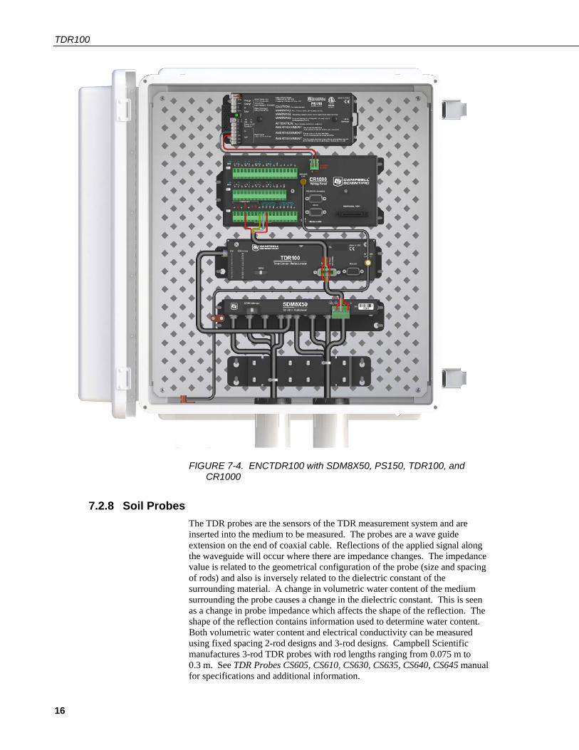
FIGURE 7-4. ENCTDR100 with SDM8X50, PS150, TDR100, and CR1000
7.2.8 Soil Probes The TDR probes are the sensors of the TDR measurement system and are inserted into the medium to be measured. The probes are a wave guide extension on the end of coaxial cable. Reflections of the applied signal along the waveguide will occur where there are impedance changes. The impedance value is related to the geometrical configuration of the probe (size and spacing of rods) and also is inversely related to the dielectric constant of the surrounding material. A change in volumetric water content of the medium surrounding the probe causes a change in the dielectric constant. This is seen as a change in probe impedance which affects the shape of the reflection. The shape of the reflection contains information used to determine water content. Both volumetric water content and electrical conductivity can be measured using fixed spacing 2-rod designs and 3-rod designs. Campbell Scientific manufactures 3-rod TDR probes with rod lengths ranging from 0.075 m to 0.3 m. See TDR Probes CS605, CS610, CS630, CS635, CS640, CS645 manual for specifications and additional information.
TDR100
17
7.2.8.1 Determining Probe Constant, Kp, using PC-TDR Section 8.1, TDR Principles (p. 19), presents the principles for TDR measurements of soil electrical conductivity. The result of the measurement must be multiplied by the probe constant (Kp) to give bulk electrical conductivity in S/m (Siemens/meter). The Kp value can be measured using PC-TDR. The method requires submersion of the TDR probe rods in de-ionized water of known temperature. See PC-TDR HELP for simple instructions.
7.3 Datalogger Programming Programming basics for CRBasic dataloggers are provided in the following sections. A complete program example for a CRBasic datalogger can be found in Appendix B, Example Program (p. B-1). Programming basics and programming examples for Edlog dataloggers are provided at www.campbellsci.com/old-manuals.
7.3.1 TDR100() CRBasic Instruction The TDR100 instruction is used to measure one or more time domain reflectivity (TDR) probes attached to a TDR100 device.
Syntax
TDR100 ( Dest, SDMAddress, Option, Mux/ProbeSelect, WaveAvg, Vp, Points, CableLength, WindowLength, ProbeLength, ProbeOffset, Mult, Offset )
Remarks
This instruction can be used to measure one TDR probe connected to the TDR100 directly or multiple TDR probes connected to one or more SDM8X50 or SDMX50 multiplexers.
Dest: The Dest parameter is a variable or variable array in which to store the results of the measurement. The variable must be dimensioned to accommodate all of the values returned by the instruction, which is determined by the Option parameter.
SDMAddress: The SDMAddress parameter defines the address of the TDR100 with which to communicate. Valid SDM addresses are 0 through 14. Address 15 is reserved for the SDMTrigger instruction. If the Reps parameter is greater than 1, the datalogger will increment the SDM address for each subsequent TDR100 that it communicates with.
CRBasic dataloggers use base 10 when addressing SDM devices. Edlog programmed dataloggers (e.g., CR10X, CR23X) used base 4 for addressing. Edlog addressing information for the SDMX50 is available in older manuals at www.campbellsci.com/old-manuals. This information is also pertinent for the SDM8X50 multiplexer.
NOTE

TDR100
18
Option: The Option parameter determines the output of the instruction.
Code Description
0 Measure La/L (ratio of apparent to physical probe rod length). Dividing La by the real rod length, L, gives the square root of dielectric constant. The La/L value is empirically related to volumetric water content using calibration functions of the form θv = f(La/L). See Section 8.1, TDR Principles (p. 19), for commonly used calibration functions.
1 Collect Waveform values – Outputs reflection waveform values as an array of floating point numbers with a range of –1 to 1. The waveform values are prefaced by a header containing values of key parameters for this instruction (averaging, propagation velocity, points, cable length, window length, probe length, probe offset, multiplier, offset)
2 Collect Waveform plus First Derivative – Returns (2*n–5)+9 values where n is the number of waveform reflection values specified by the Points parameter.
3 Measure Electrical Conductivity – Outputs a value that when multiplied by the Multiplier parameter determines soil bulk electrical conductivity in S/m.
Mux/ProbeSelect: The Mux/Probe Select parameter is used to define the setup of any multiplexers and attached probes in the system. The addressing scheme used is ABCR, where A = level 1 multiplexer channel, B = level 2 multiplexer channel, C = level 3 multiplexer channel, and R = the number of consecutive probes to be read, starting with the channel specified by the ABC value (maximum of 8). 0 is entered for any level not used.
WaveAvg: The WaveAvg parameter is used to define the number of waveform reflections averaged by the TDR100 to give a single result. A waveform averaging value of 4 provides good signal-to-noise ratio under typical applications. Under high noise conditions averaging can be increased. The maximum averaging possible is 128.
Vp: The Vp parameter allows you to enter the propagation velocity of a cable when using the instruction to test for cable lengths or faults. Vp adjustment is not necessary for soil water content or electrical conductivity measurement and should be set to 1.0 for output Option 1, 2, or 3.
Points: The Points parameter is used to define the number of values in the displayed or collected waveform (20 to 2048). An entry of 251 is recommended for soil water measurements. The waveform consists of the number of Points equally spaced over the WindowLength.
CableLength: The CableLength parameter is used to specify the cable length, in meters, of the TDR probes. If a 0 is entered for the Option parameter, cable length is used by the analysis algorithm to begin searching for the TDR probe. If a 1 or 2 is entered for the Option parameter, cable length is the distance to the start of the collected waveform.
The value used for CableLength is best determined using PC-TDR100 with the Vp = 1.0. Adjust the CableLength and WindowLength values in PC-TDR100

TDR100
19
until the probe reflection can be viewed. Subtract about 0.5 meters from the distance associated with the beginning of the probe reflection.
Note that the specified CableLength applies to all probes read by this instruction; therefore, all probes must have the same cable lengths.
WindowLength: The WindowLength parameter specifies the length, in meters, of the waveform to collect or analyze. The waveform begins at the CableLength and ends at the CableLength + WindowLength. This is an apparent length because the value set for Vp may not be the actual propagation velocity. For water content measurements, the WindowLength must be large enough to contain the entire probe reflection. For probes with 20 to 30 cm rods. A Vp = 1 and Window length = 5 is recommended. See TABLE 7-1 for recommended window lengths for other probes.
ProbeLength: The ProbeLength parameter specifies the length, in meters, of the probe rods that are exposed to the medium being measured. The value of this parameter only has an affect when Option 0, La/L, is used for the measurement.
ProbeOffset: The ProbeOffset is an apparent length value used to correct for the portion of the probe rods that may be encapsulated in epoxy and not surrounded by soil or other medium being measured. This value is supplied by Campbell Scientific for the probes we manufacture. The value of this parameter only has an affect when Option 0, La/L, is used for the measurement.
Mult, Offset: The Mult and Offset parameters are each a constant, variable, array, or expression by which to scale the results of the measurement.
8. Operation 8.1 TDR Principles
The travel time for a pulsed electromagnetic signal along a waveguide is dependent on the velocity of the signal and the length of the waveguide. The velocity is dependent on the dielectric constant of the material surrounding the waveguide. This relationship can be expressed by
∆t
L Kc
a=2
[1]
Where Ka is the apparent dielectric constant, c is the velocity of electromagnetic signals in free space, ∆t is the travel time, and L is the waveguide length. The dielectric constant of water relative to other soil constituents is high. Consequently, changes in volumetric water content can be directly related to the change in the dielectric constant of bulk soil material. Equation [1] can be simplified to express the apparent dielectric constant as the ratio of the apparent probe length (La = c ∆t/2) to the real probe length.
KLLa
a= [2]

TDR100
20
The relationship between dielectric constant and volumetric water content has been described by, among others, Topp et al. (1980) and Ledieu et al. (1986) in an empirical fashion using both polynomial and linear forms. These expressions are presented here since it has been shown in numerous research efforts that these equations are appropriate for nearly all applications. With θv the volumetric water content, the equation presented by Topp et al. (1980) is
θv a a aK K K= − ∗ + ∗ − ∗ + ∗− − − −53 10 2 92 10 55 10 4 3 102 2 4 2 6 3. . . . [3]
and that presented by Ledieu et al. (1986) is
θv aK= −01138 01758. . [4]
The TDR100 generates a very fast rise time pulse that is sent to the connecting cable and probe. Reflections over a specified length of transmission line are sampled and digitized. Discontinuities in cable impedance will cause changes in the amplitude of the reflected signal. The travel time of the reflected signal is used with a velocity value to give distance information. A probe consisting of metal rods can be used as an extension of a coaxial cable. When the probe is inserted in the soil, the travel time of the applied pulse along the probe length will depend on the soil water content. In general, as the water content increases, the travel time of the applied pulse increases. The reflected waveform of the probe can be used to identify the impedance transitions caused by the probe beginning and end. This information is then analyzed to determine soil water content.
While the velocity of the applied pulse along a waveguide is dependent on the dielectric constant of the material surrounding the waveguide, the amplitude of the reflected voltage is dependent on electrical conduction of the applied signal between probe rods. The presence of free ions in the soil solution will result in attenuation of the applied signal. Theory presented by Giese and Tiemann (1975) has been applied to the measurement of soil bulk electrical conductivity. A commonly used expression is
σ
ρρ
=−+
KZ
p
c
11 [5]
where σ is the bulk electrical conductivity, Kp is a probe constant, Zc is the cable impedance (50 ohm), and ρ is the reflection coefficient. The reflection coefficient is the ratio of the reflected voltage to the applied voltage and ranges between plus and minus one.
The components of the Campbell Scientific TDR system are designed to apply time domain reflectometry for the determination of soil volumetric water content and bulk electrical conductivity as both hardware for the collection of data and software for communications and analysis of the data.

TDR100
21
8.2 Cable Length and Soil Electrical Conductivity Effect on Water Content Determination
8.2.1 Cable Length Effect on Water Content Measurement The determination of water content using the TDR system relies on the evaluation of a pulse reflection from the TDR probe. The pulse generated by the TDR100 and its reflections are subject to distortion during travel between the TDR100 and the TDR probe. The cable connecting the probe to the reflectometer has a characteristic impedance resulting in both resistive and reactive losses. Distortion of the waveform caused by cable impedance can introduce error into the water content determination.
FIGURE 8-1 presents waveforms collected from a 3-rod probe (CS610) for various cable lengths. As cable length increases, the rise time and the amplitude of the reflection are affected. The slopes and extrema used by the datalogger algorithm to analyze the waveform are shifted by the cable losses resulting in error. For the data shown in FIGURE 8-1, the water content measurement using the 66 meter cable was in error by about 1.5% volumetric water content when electrical conductivity is low. However, in saline soils the error can be several percent. See Bilskie (1997) for complete results of the study.
FIGURE 8-1. Waveforms collected in a sandy loam using CS610 probe with RG8 connecting cable. Volumetric water content is 24% and bulk electrical conductivity is 0.3 dS m–1.
In general, water content is overestimated with increasing cable length. A calibration of volumetric water content with apparent dielectric constant for a given cable length can improve accuracy. Measurement precision at longer cable lengths will be maintained as long as soil electrical conductivity does not prevent a reflection from the end of the probe rods. This is discussed later in this section.
16 meter cable26 meter cable45 meter cable66 meter cable

TDR100
22
Minimizing cable lengths should always be considered in the design of a measurement system using TDR. If long cable lengths are necessary, the adverse effects can be minimized by using low attenuation cable such as RG8. Careful probe design ensures correct probe impedance giving robust reflections. All TDR probes offered by Campbell Scientific are designed to optimize accuracy when longer cable lengths are used.
8.2.2 Soil Electrical Conductivity Effect on Water Content Measurement The signal at the probe will be attenuated when ionic conduction occurs in the soil solution. This inherent attenuation is used in TDR measurements to determine soil electrical conductivity as described by equation [5]. The presence of ions in the soil solution provides a path for electrical conduction between TDR probe rods. The attenuation of the signal can affect the accuracy and resolution of water content measurements. FIGURE 8-2 presents a series of waveforms when a solution with an electrical conductivity of 1.0 dS m–1 is added to a soil which has essentially no salt present. FIGURE 8-3 shows data for solution with high electrical conductivity.
FIGURE 8-2. Waveforms collected in a sandy loam using CS610 probe with RG8 connecting cable. Volumetric water content values are 10, 16, 18, 21 and 25%. Solution electrical conductivity is 1.0 dS m–1.
water content = 9.5%
water content = 25%
TDR100
23
FIGURE 8-3. Waveforms collected in a sandy loam using CS610 probe with RG8 connecting cable. Volumetric water content values are 10, 18, 26, 30 and 37%. Solution electrical conductivity is 10.2 dS m–1.
The combined effect of long cable runs and high soil electrical conductivity must be considered when TDR measurements are taken.
8.3 Algorithm Description and Parameter Adjustment This section presents a general description of the algorithms in the TDR100 for electrical conductivity and water content measurement.
8.3.1 Algorithm for Calculation of TDR Probe Rod Apparent Length Equation [2] of Section 8.1, TDR Principles (p. 19), shows the relationship between apparent dielectric constant, Ka, and apparent TDR probe rod length, La. The equation is repeated here for convenience. L is the actual rod length.
[2]
Ka is calculated using equation [2] then converted to volumetric water content using empirical equations such as equations [3] and [4] of Section 8.1, TDR Principles (p. 19).
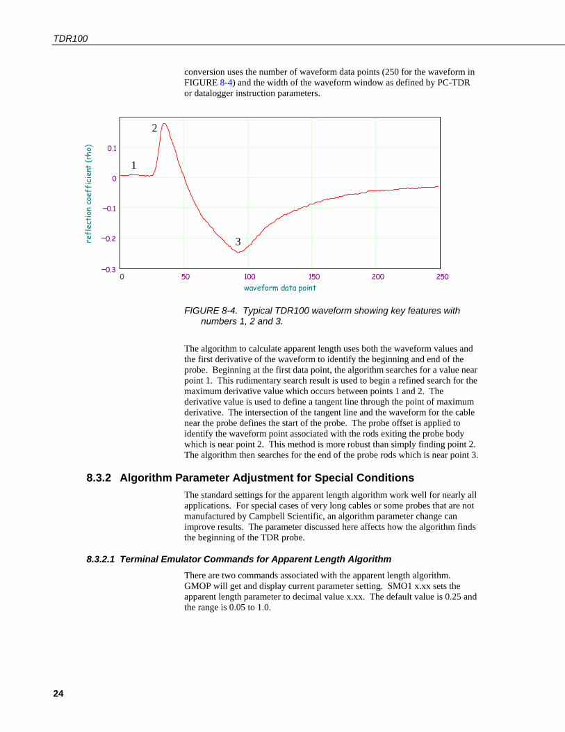
8.3.1.1 Waveform Evaluation FIGURE 8-4 shows a typical waveform and identifies key points. The waveform before point 1 is the section of coaxial cable near the probe head with point 1 the transition from the 50 ohms of the cable to the impedance of the probe. The change in reflection coefficient between points 1 and 2 is related to the difference in impedance between the cable and the probe. Point 2 corresponds to the rods exiting the probe head and point 3 is the end of the probe rods. The apparent length relates to the difference between point 2 to point 3 and is obtained by converting waveform data points to distance. The
water content = 18%
water content = 37%
KLLa
a=
TDR100
24
conversion uses the number of waveform data points (250 for the waveform in FIGURE 8-4) and the width of the waveform window as defined by PC-TDR or datalogger instruction parameters.
FIGURE 8-4. Typical TDR100 waveform showing key features with numbers 1, 2 and 3.
The algorithm to calculate apparent length uses both the waveform values and the first derivative of the waveform to identify the beginning and end of the probe. Beginning at the first data point, the algorithm searches for a value near point 1. This rudimentary search result is used to begin a refined search for the maximum derivative value which occurs between points 1 and 2. The derivative value is used to define a tangent line through the point of maximum derivative. The intersection of the tangent line and the waveform for the cable near the probe defines the start of the probe. The probe offset is applied to identify the waveform point associated with the rods exiting the probe body which is near point 2. This method is more robust than simply finding point 2. The algorithm then searches for the end of the probe rods which is near point 3.
8.3.2 Algorithm Parameter Adjustment for Special Conditions The standard settings for the apparent length algorithm work well for nearly all applications. For special cases of very long cables or some probes that are not manufactured by Campbell Scientific, an algorithm parameter change can improve results. The parameter discussed here affects how the algorithm finds the beginning of the TDR probe.
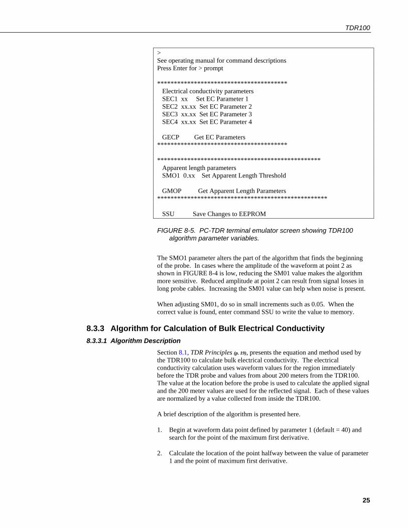
8.3.2.1 Terminal Emulator Commands for Apparent Length Algorithm There are two commands associated with the apparent length algorithm. GMOP will get and display current parameter setting. SMO1 x.xx sets the apparent length parameter to decimal value x.xx. The default value is 0.25 and the range is 0.05 to 1.0.
0 50 100 150 200 2500.3
0.2
0.1
0
0.1
waveform data point
refl
ecti
on c
oeff
icie
nt (r
ho)
1
2
3
TDR100
25
> See operating manual for command descriptions Press Enter for > prompt *************************************** Electrical conductivity parameters SEC1 xx Set EC Parameter 1 SEC2 xx.xx Set EC Parameter 2 SEC3 xx.xx Set EC Parameter 3 SEC4 xx.xx Set EC Parameter 4 GECP Get EC Parameters *************************************** ************************************************* Apparent length parameters SMO1 0.xx Set Apparent Length Threshold GMOP Get Apparent Length Parameters *************************************************** SSU Save Changes to EEPROM
FIGURE 8-5. PC-TDR terminal emulator screen showing TDR100 algorithm parameter variables.
The SMO1 parameter alters the part of the algorithm that finds the beginning of the probe. In cases where the amplitude of the waveform at point 2 as shown in FIGURE 8-4 is low, reducing the SM01 value makes the algorithm more sensitive. Reduced amplitude at point 2 can result from signal losses in long probe cables. Increasing the SM01 value can help when noise is present.
When adjusting SM01, do so in small increments such as 0.05. When the correct value is found, enter command SSU to write the value to memory.
8.3.3 Algorithm for Calculation of Bulk Electrical Conductivity 8.3.3.1 Algorithm Description
Section 8.1, TDR Principles (p. 19), presents the equation and method used by the TDR100 to calculate bulk electrical conductivity. The electrical conductivity calculation uses waveform values for the region immediately before the TDR probe and values from about 200 meters from the TDR100. The value at the location before the probe is used to calculate the applied signal and the 200 meter values are used for the reflected signal. Each of these values are normalized by a value collected from inside the TDR100.
A brief description of the algorithm is presented here.
1. Begin at waveform data point defined by parameter 1 (default = 40) and search for the point of the maximum first derivative.
2. Calculate the location of the point halfway between the value of parameter 1 and the point of maximum first derivative.

TDR100
26
3. Calculate the mean and standard deviation of waveform values between parameter 1 and the halfway point.
4. Calculate a threshold value using: threshold = a*(maximum derivative) + b*(mean from step 3) + c*(standard deviation from step 3) The default values for a, b and c are 0, 1 and 2 respectively.
5. With the point of the maximum first derivative as the right hand point, define a window of 10 waveform values. Incrementally move this window toward the TDR100 until all values are less than the threshold calculated in step 4.
6. Calculate the average of this window of values and use for the applied signal.
7. Calculate the average of the last six waveform values and use for reflected signal.
8. Apply equation [5] of Section 8.1, TDR Principles (p. 19), to calculate electrical conductivity.
8.3.3.2 Algorithm Parameter Adjustment for Special Conditions Under conditions of very long TDR probe cables, signal loss can lead to erroneous electrical conductivity measurements. Parameters can be adjusted using the terminal emulator mode of PC-TDR to optimize measurements under these conditions.
FIGURE 8-5 lists the parameter adjustment commands and the required numerical format. The commands are discussed in detail here. These commands are active only in the terminal emulator mode of PC-TDR which is reached using menu Options/Terminal Emulator.
To view the current parameter values type GECP at the > prompt. The values of the 4 parameters are returned.
The default values for the threshold equation are:
a = 0 b = 1 c = 2
Therefore the default threshold is the mean plus twice the standard deviation of the values in the 10-point window before the probe. All values in the window must be below the threshold value.
The threshold equation was chosen to provide flexibility when conditions of noise or large amount of signal attenuation are present.
threshold = a*(maximum derivative) + b*(mean from step 3) + c*(standard deviation from step 3)

TDR100
27
FIGURE 8-6. Waveform and derivative values near TDR probe and locations of index for point of maximum derivative and maximum derivative value. The green band represents the results of the search using the threshold value.
9. References Bilskie, Jim. 1997. “Reducing Measurement Errors of Selected Soil Water Sensors. Proceedings of the International Workshop on Characterization and measurement of the hydraulic properties of unsaturated porous media. 387-396.
Topp, G.C., J.L. Davis & A.P. Annan. 1980. “Electromagnetic determination of soil water content: measurements in coaxial transmission lines,” Water Resources Research, v. 16, No. 3:574-582.
Ledieu, J., P. De Ridder, P. De Clerck, and S. Dautrebande. 1986. “A method of measuring soil moisture by time-domain reflectometry,” J. Hydrol. 88:319-328.
Giese, K., and R. Tiemann. 1975. “Determination of the complex permittivity from thin-sample time domain reflectometry, Improved analysis of the step response waveform,” Adv. Molec. Relax. Processes 7:45-49
Rhoades, J.D., N.A. Manteghi, P.J. Shouse, and W.J. Alves. 1989. Soil electrical conductivity and soil salinity: New formulations and calibrations. Soil Sci Soc. Am. J. 53:433-439.
840 860 880 900 920 940 960 980 1000
0
0.1
0.2
0.3
0.4
0.5
waveformwaveform derivativevalues used for applied signal
waveform and derivative near probe
data point
refl
ecti
on c
oeff
icie
nt
max_deriv
indexmax_derivative

TDR100
28
Rhoades, J.D., P.A.C. Raats, and R.J. Prather. 1976. Effects of liquid-phase electrical conductivity, water content and surface conductivity on bulk soil electrical conductivity. Soil Sci. Soc. Am. J. 40:651-655.

A-1
Appendix A. SDMX50-Series Multiplexers A.1 General
Prior to the SDM8X50, the SDMX50 series multiplexers were used with the TDR100 to measure multiple sensors. The SDMX50SP was identical to the SDM8X50 in form, fit, and function. The SDMX50 came with the multiplexer mounted in a 10” x 12” enclosure, similar to the SDM8X50-E. The SDMX50LP included the backplate and multiplexer found in the SDMX50 but shipped without an enclosure.
SDMX50 multiplexers may be used interchangeably with SDM8X50 multiplexers. The major difference between them is that the SDM8X50 uses hermetically sealed, longer lasting electromechanical relays and provides better surge protection than the SDMX50 series.
A.2 Specifications A.2.1 Physical
Consists of Size When Used
SDMX50 50 Ohm Coaxial Multiplexer with Enclosure
Multiplexer circuit board mounted in an environmental enclosure with a strain relief backplate. Enclosure includes a bracket for mounting to a tripod, tower, or a 1.0 in. to 1.25 in. IPS Schedule 40 pipe.
Weight: 4.4 kg (9.8 lb) Enclosure Outside Dimensions with Mounts: 40.4 x 29.2 x 17.5 cm (15.9 x 11.5 x 6.9 in) Enclosure Inside Dimensions: 25.4 x 30.4 x 12.7 cm (10 x 12 x 5 in)
When the multiplexer will be housed in its own enclosure without the datalogger and power supply.
SDMX50LP 50 Ohm Multiplexer with 10 in. x 12 in. Backplate
Multiplexer circuit board attached to one end of a strain relief backplate.
Circuit Board Dimensions: 24.9 x 12.2 x 4.6 cm (9.8 x 4.8 x 1.8 in) Strain Relief Backplate Dimensions 26.7 x 27.9 x 1.3 cm (10.5 x 11 x 0.5 in)
When a user-supplied enclosure will house only the multiplexer without the datalogger and power supply.
Appendix A. SDMX50-Series Multiplexers
A-2
SDMX50SP 50 Ohm Coaxial Multiplexer with Strain Relief Bracket
Multiplexer circuit board encased in metal housing and a separate strain relief bracket. Both the circuit board and bracket include mounting holes and hardware for attaching them to the backplate of an enclosure (typically the ENCTDR100) or to a wall.
Weight: 590 g (1.3 lb) Multiplexer Housing Dimensions with Mounts: 24.9 x 12.2 x 4.6 cm (9.8 x 4.8 x 1.8 in) Strain Relief Bracket Dimensions: 20.3 x 4.3 x 1.3 cm (8.0 x 1.7 x 0.5 in)
When the multiplexer will be housed in the same enclosure as the datalogger and power supply or when the multiplexer will reside in a building.
Temperature Range: –40 to 55 °C
A.2.2 Electrical Input power: 12 Vdc
Quiescent current drain: < 1 mA
Current drain during switching: ~90 mA (all multiplexers of the same level switch simultaneously for less than 1 s. See FIGURE 7-2.)
Relay Contact Life Expectancy: 5 x 10⁶ operations
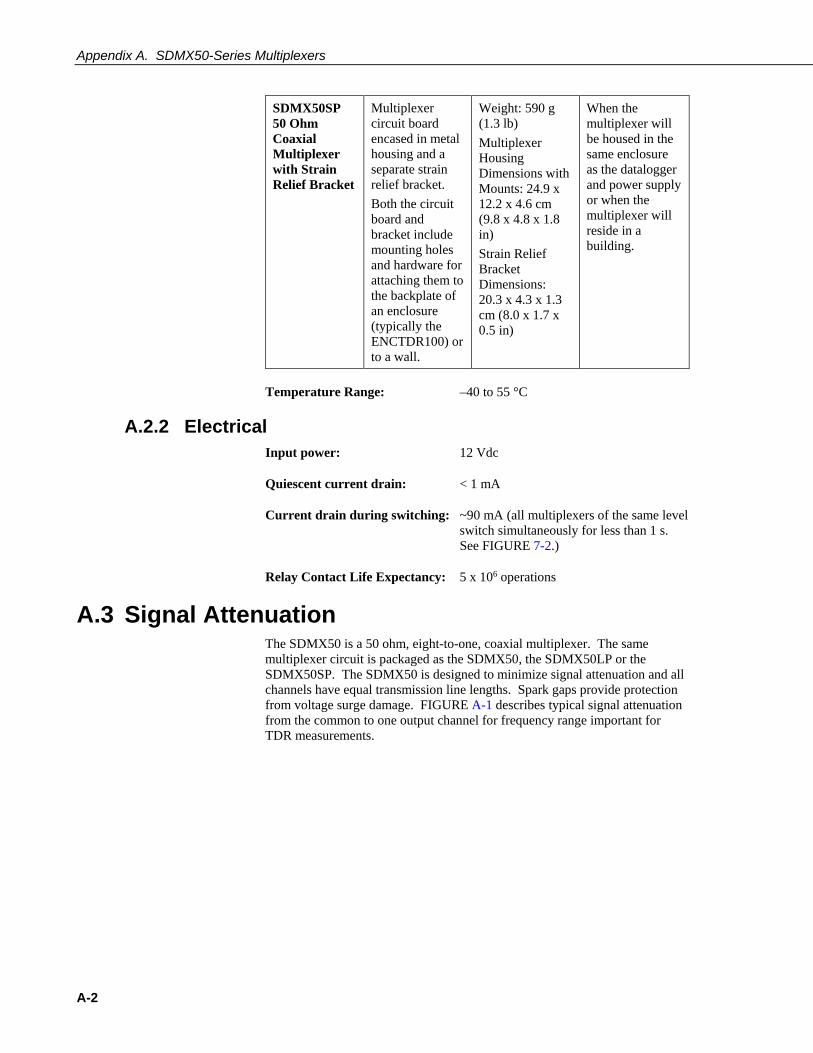
A.3 Signal Attenuation The SDMX50 is a 50 ohm, eight-to-one, coaxial multiplexer. The same multiplexer circuit is packaged as the SDMX50, the SDMX50LP or the SDMX50SP. The SDMX50 is designed to minimize signal attenuation and all channels have equal transmission line lengths. Spark gaps provide protection from voltage surge damage. FIGURE A-1 describes typical signal attenuation from the common to one output channel for frequency range important for TDR measurements.

Appendix A. SDMX50-Series Multiplexers
A-3
100 1 .1031.4
1.2
1
0.8
0.6
0.4
0.2
0
Frequency (MHz)
SD
MX
50 a
tten
uati
on (d
Bm)
FIGURE A-1. SDMX50 signal attenuation
Each of the eight ports can be connected to a probe or another multiplexer (see FIGURE 7-2).
A.4 SDM Communication A.4.1 SDM Addressing for TDR100 System
Addressing for SDMX50 multiplexers with serial number 5238 and higher is set using the thumbwheel switch at the top of the panel. Addressing for SDMX50 multiplexers with serial number 5237 and lower is set with hardware jumpers. Changing the SDMX50 jumpers requires removing the multiplexer front cover. FIGURE A-2 shows the location of jumpers used for SDMX50 addressing. Edlog dataloggers use base 4 addresses. A table that lists the Edlog addresses and jumper positions is provided in the 2/10 version of the TDR100 manual available at www.campbellsci.com/old-manuals.
It is recommended to use a TDR100 address of 0, level 1 SDMX50 address of 01, level 2 SDMX50 address of 02, and level 3 SDMX50 address of 03.

Appendix A. SDMX50-Series Multiplexers
A-4
FIGURE A-2. Location of address jumpers on SDMX50

B-1
Appendix B. Example Program B.1 CR1000 Program Example
This CR1000 program measures and records analog measurements and volumetric water content. It also captures the TDR probe waveforms.
Equipment Wiring
CR1000 TDR100 SDM8X50
SW12 +12 V 12 V
G G G
C1 C1 C1
C2 C2 C2
C3 C3 C3
Sensor Wiring
TDR100 SDM8X50 TDR Probe*
Coax Common
Channel_1 Probe 1
Channel_2 Probe 2
Channel_3 Probe 3
Channel_4 Probe 4
Channel_5 Probe 5
Channel_6 Probe 6
Channel_7 Probe 7
Channel_8 Probe 8
*Note: TDR probe cable length must be determined using PC-TDR!

Appendix B. Example Program
B-2
'CR1000 Series Datalogger 'program: c:\mydoc\cr1000\cr1000-testing\TDR&SDM&F1&Wave_CR1K.CR1 'Measure and Record Analog Measurements, Volumetric Water Content, & Store Waveforms ' 'Declare Public & Dim Variables ------------------------------------ Public batt_volt Public Panel_temp Public LaL(8) Public LaL2(8) Public LedieuVWC(8) Public ToppVWC(8) Public Flag(2) Dim WavePT(260) 'To conserve datalogger memory, use Dim instead of Public for waveform data points. public MuxChan Dim I 'Declare Constants ------------------------------------------------ 'Topp Equation Dielectric Constants const a0= -0.053 const a1= 0.0292 const a2= -0.00055 const a3= 0.0000043 I const high = true const low = false 'Define Data Tables ---------------------------------------------- DataTable (Dat15min,1,-1) '15-minute Data Table (i.e. Analog Measurements) DataInterval (0,15,Min,10) Minimum (1,batt_volt,IEEE4,0,False) Average (1,Panel_temp,IEEE4,0) EndTable DataTable (Data_TDR,1,-1) '2-Hour Data Table (i.e. TDR100 VWC Measurements) DataInterval (0,120,Min,10) Minimum (1,batt_volt,IEEE4,0,False) Average (1,Panel_temp,IEEE4,0) Sample (8,LaL(),IEEE4) sample (8,LedieuVWC(),FP2) sample (8,ToppVWC(),FP2) EndTable ' DataTable (TDR_Wave,1,240) 'Data Table (i.e. Capture TDR Probe Waveforms) sample (1,MuxChan,IEEE4) sample (260,WavePT(),FP2) EndTable 'Note: The DataTable "TDR_Wave" data storage area is NOT and should NOT be auto allocated 'in this program example!!! Therefore, "TDR_Wave" memory storage size should be allocated 'by the programmer. How to calculate memory storage size? 'Example: In this program when F2 goes high there are 8ea calls to "TDR_Wave", repeated 'let's say 30 times, will allocate memory for 240 waveforms. "DataTable (TDR_Wave,1,240)" ' 'Main Program --------------------------------------------------- BeginProg SDMSpeed (50) 'Fix TDR100 to CR1K communication timing ' Scan (5,Sec,0,0) 'scan instructions every 5 sec Battery (Batt_volt) PanelTemp (Panel_temp,250) CallTable Dat15min ' 'Set flag 1 High every 120 minutes (Note: User can manually set flag 1 high/low) If TimeIntoInterval(0,2,Hr) Then Flag(1)=High 'Set flag 2 High once per day (Note: User can manually set flag 2 high/low) If TimeIntoInterval(0,24,Hr) then flag(2)=high '

Appendix B. Example Program
B-3
If Flag(1)=High Then '************************************* SW12 (1) 'Turn on 12V Power to TDR100 & SDMX50 'Note: Wire TDR100 & SDM8X50 12V power leads to CR1000 SW12 Terminal Delay (1,2,Sec) 'pause 2 sec to allow power supply voltage to settle ' 'Measure La/L on SDMX50 channel #1 thru channel#8 & convert to VWC using Topp Eq. TDR100 (LaL(1),0,0,1001,4,1.0,251,9.5,5.0,0.3,0.085,1,0) TDR100 (LaL(2),0,0,2001,4,1.0,251,9.0,5.0,0.3,0.085,1,0) TDR100 (LaL(3),0,0,3001,4,1.0,251,8.5,5.0,0.3,0.085,1,0) TDR100 (LaL(4),0,0,4001,4,1.0,251,9.5,5.0,0.3,0.085,1,0) TDR100 (LaL(5),0,0,5001,4,1.0,251,7.0,5.0,0.3,0.085,1,0) TDR100 (LaL(6),0,0,6001,4,1.0,251,10.5,5.0,0.3,0.085,1,0) TDR100 (LaL(7),0,0,7001,4,1.0,251,11.5,5.0,0.3,0.085,1,0) TDR100 (LaL(8),0,0,8001,4,1.0,251,9.5,5.0,0.3,0.085,1,0) For I=1 to 8 LaL2(I) = LaL(I)^2 'Apparent Dielectric Constant K = (La/L)^2 Next I 'Topp Conversion from Dielectric Constant to Volumetric Water Content (VWC) For I=1 to 8 ToppVWC(I)=a0 + a1*LaL2(I) + a2*LaL2(I)^2 + a3*LaL2(I)^3 Next I ' 'Measure La/L on SDM8X50 channel #1 thru channel#8 & convert to VWC using Ledieu Eq. 'Note: Reps (i.e. "1008") assume all cables are the same length!!! TDR100 (LedieuVWC(),0,0,1008,4,1.0,251,9.5,5.0,0.3,0.085,.1138,-0.1758) ' CallTable Data_TDR Flag(1)=0 'reset state of Flag 1 SW12 (0 ) 'Switched 12V Low endif 'EndIf for Flag 1 *********************** If Flag(2)=High Then '************************************* SW12 (1) 'Turn on 12V Power to TDR100 & SDMX50 Delay (0,2,Sec) 'pause 2 sec to allow power supply voltage to settle out ' MuxChan=1001 'store the SDM8X50 channel in variable "MuxChan" TDR100 (WavePT(),0,1,1001,4,1.0,251,9.5,5.0,0.3,0.085,1,0) CallTable TDR_Wave() ' MuxChan=2001 'store the SDM8X50 channel in variable "MuxChan" TDR100 (WavePT(),0,1,2001,4,1.0,251,9.5,5.0,0.3,0.085,1,0) CallTable TDR_Wave() ' MuxChan=3001 TDR100 (WavePT(),0,1,3001,4,1.0,251,9.5,5.0,0.3,0.085,1,0) CallTable TDR_Wave() ' MuxChan=4001 TDR100 (WavePT(),0,1,4001,4,1.0,251,9.5,5.0,0.3,0.085,1,0) CallTable TDR_Wave() ' MuxChan=5001 TDR100 (WavePT(),0,1,5001,4,1.0,251,9.5,5.0,0.3,0.085,1,0) CallTable TDR_Wave() ' MuxChan=6001 TDR100 (WavePT(),0,1,6001,4,1.0,251,9.5,5.0,0.3,0.085,1,0) CallTable TDR_Wave() ' MuxChan=7001 TDR100 (WavePT(),0,1,7001,4,1.0,251,9.5,5.0,0.3,0.085,1,0) CallTable TDR_Wave() ' MuxChan=8001 TDR100 (WavePT(),0,1,8001,4,1.0,251,9.5,5.0,0.3,0.085,1,0) CallTable TDR_Wave() '

Appendix B. Example Program
B-4
Flag(2)=0 'reset state of Flag 2 SW12 (0 ) 'Switched 12V Low endif 'EndIf ******************************** ' PortsConfig (&B00000111,&B00000000) 'configure SDM ports C1,C2,C3 as inputs ' NextScan EndProg


Campbell Scientific Companies
Campbell Scientific, Inc. (CSI) 815 West 1800 North Logan, Utah 84321 UNITED STATES
www.campbellsci.com • [email protected]
Campbell Scientific Africa Pty. Ltd. (CSAf) PO Box 2450
Somerset West 7129 SOUTH AFRICA
www.csafrica.co.za • [email protected]
Campbell Scientific Australia Pty. Ltd. (CSA) PO Box 8108
Garbutt Post Shop QLD 4814 AUSTRALIA
www.campbellsci.com.au • [email protected]
Campbell Scientific (Beijing) Co., Ltd. 8B16, Floor 8 Tower B, Hanwei Plaza
7 Guanghua Road Chaoyang, Beijing 100004
P.R. CHINA www.campbellsci.com • [email protected]
Campbell Scientific do Brasil Ltda. (CSB) Rua Apinagés, nbr. 2018 ─ Perdizes CEP: 01258-00 ─ São Paulo ─ SP
BRASIL www.campbellsci.com.br • [email protected]
Campbell Scientific Canada Corp. (CSC) 14532 – 131 Avenue NW Edmonton AB T5L 4X4
CANADA www.campbellsci.ca • [email protected]
Campbell Scientific Centro Caribe S.A. (CSCC) 300 N Cementerio, Edificio Breller
Santo Domingo, Heredia 40305 COSTA RICA
www.campbellsci.cc • [email protected]
Campbell Scientific Ltd. (CSL) Campbell Park
80 Hathern Road Shepshed, Loughborough LE12 9GX
UNITED KINGDOM www.campbellsci.co.uk • [email protected]
Campbell Scientific Ltd. (CSL France) 3 Avenue de la Division Leclerc
92160 ANTONY FRANCE
www.campbellsci.fr • [email protected]
Campbell Scientific Ltd. (CSL Germany) Fahrenheitstraße 13
28359 Bremen GERMANY
www.campbellsci.de • [email protected]
Campbell Scientific Spain, S. L. (CSL Spain) Avda. Pompeu Fabra 7-9, local 1
08024 Barcelona SPAIN
www.campbellsci.es • [email protected]
Please visit www.campbellsci.com to obtain contact information for your local US or international representative.