installation & operation manual...8 | falcon global installation and operations guide (v1.1)...
TRANSCRIPT

InstallatIon & operatIon manual
GLOBAL
FSK1600022 - Falcon Global Manual Cover_v1.indd 1 2016/04/13 2:44 PM


INDEX
1. INTRODUCTION
2. FEATURES AND FUNCTIONS2.1 Reporting Options ....................................................................
2.2 Interfaces ...................................................................................... 2.3 Programming .............................................................................
2.4 Indicators and Controls ........................................................
3. INSTALLATION3.1 Falcon Global Wiring ..............................................................
3.1.1 Power Supply ................................................................... 3.1.2 Check AC ........................................................................... 3.1.3 Dry Contact Inputs ........................................................... 3.1.4 Contact ID Inputs ............................................................. 3.1.5 Serial Port ........................................................................... 3.1.6 Relay Outputs ...................................................................
3.2 Falcon Global Installation ........................................................
3.3 GSM Connection and Signal Strength ............................3.4 Selecting the Alarm Panel Serial Port Format ......................................... 3.5 Indicators and Controls .........................................................
.............................................................. 5
.............................................................. 7
............ 6
6
6
6
6
788899101010
12
13

4. PROGRAMMING4.1 On-Board Push Button ........................................................ 17
4.2 PC based Programmer ........................................................ 17
Appendix A Serial Interface
Appendix B Programming Cable and Software ................................... 19
... 27
.................................................... 17
Falcon Global Installation and Operations Guide (v1.1) | 5
1. IntroductionThe FSK Falcon Global is a highly featured GSM based unit which is used for the transmission of Security and Telemetry messages over the GSM network.
The Falcon can communicate via GPRS messages to a Control Room and includes the universal Contact ID interface to Alarm Control Panels as well as serial interfacing into some leading panels. It also has seven dry contact input triggers
In addition, the Falcon has two outputs which can be used to command Alarm Panels and other devices.
GLOBAL

6 | Falcon Global Installation and Operations Guide (v1.1)
2. Features & Functions
2.1 Reporting Options• Global SIM card operation for enhanced network reliability• GPRS reporting to a control room
2.2 Interfaces• 7 Hardwired inputs with positive trip, negative trip or both• Dedicated AC Supply monitoring input• 2 on-board relay outputs which can be controlled by GPRS• Contact ID TIP and RING telephone interface to all leading
control panels• Serial alarm interface to leading control panels• Over-the-air Panel Uploading and Downloading on the Rhino
and Texecom Premier control panels through the serial interface
2.3 Programming• Full programming and software updating via a computer serial
port• Programming over-the-air via GPRS
2.4 Indicators and Controls• Status and error indication via a seven segment display• Serial port selection via the on-board push-button
GLOBAL

Falcon Global Installation and Operations Guide (v1.1) | 7
3. Installation
3.1 Falcon Global Wiring Connections to the Falcon are shown below:
PR
OG
RA
MM
ING
/ C
OM
MU
NIC
ATION
SE
RIA
L P
OR
T
AC
MO
NITO
R
12V D
C FR
OM
B
ATTER
Y
INPUTS
RE
LAY 1
RE
LAY 2
RIN
GTIP
CO
NTA
CT ID
DTM
F TE
LEP
HO
NE
CO
NN
EC
TION
S
GLOBAL

8 | Falcon Global Installation and Operations Guide (v1.1)
3.1.1 Power SupplyThe Falcon must be connected to a stable 12V DC (nominal 13.2V) power supply. If a battery is available in the alarm panel, it must preferably be powered directly from the battery.
3.1.2 Check AC The Check AC (CAC) input detects the presence of the AC supply and is used to check for power failure. The CAC line should be connected to one of the transformer’s SECONDARY terminals. Do NOT connect this line to the mains.
The CAC line will detect AC voltages between 10 and 24V.
If the CAC line is not connected, the Falcon should not be programmed to send AC Failure or Restoral Signals.
The AC Failure and AC Restore signals have a programmable delay (default set at 10 minutes) in order to prevent false triggers.
3.1.3 Dry Contact InputsThe dry contact inputs can be used to detect alarms generated from the outputs of the Alarm Panel or from other sources.
If the external device generates the alarm by pulling the input to ground (negative trigger), the pull-up jumper should be inserted on the input of the Falcon.
GLOBAL
Falcon Global Installation and Operations Guide (v1.1) | 9
3.1.4 Contact ID InputsThe Falcon can ‘intercept’ signals sent by the alarm panel on its telephone line (Contact ID) interface.
If the Contact ID interface is to be used, the Alarm Panel’s TIP and RING lines should be connected to the TIP and RING lines on the Falcon.
The alarm panel must be programmed to use its dialer, and the option for reporting must be set to Contact ID. Refer to the programming manual of the applicable Alarm Panel.
The Falcon can be programmed to use its own account code or the account code of the alarm panel when sending alarms received via the Contact ID interface.
3.1.5 Serial PortThe Falcon can receive alarms from the following alarm panels on its serial port:• Rhino8zoneand16Zonealarmpanels• Texecompremierrange(paneluploadsanddownloadscanalso
be done)• ParadoxE65,SP6000andMG5050• Pima• IDS• DSC
GLOBAL
10 | Falcon Global Installation and Operations Guide (v1.1)
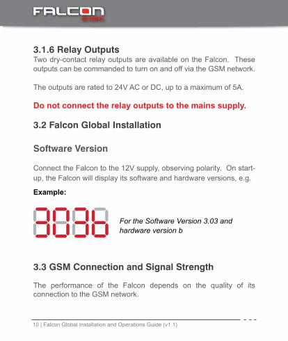
3.1.6 Relay OutputsTwo dry-contact relay outputs are available on the Falcon. These outputs can be commanded to turn on and off via the GSM network.
The outputs are rated to 24V AC or DC, up to a maximum of 5A.
Do not connect the relay outputs to the mains supply.
3.2 Falcon Global Installation
Software Version
Connect the Falcon to the 12V supply, observing polarity. On start-up, the Falcon will display its software and hardware versions, e.g.
8888 For the Software Version 3.03 and hardware version b
Example:
3.3 GSM Connection and Signal Strength
The performance of the Falcon depends on the quality of its connection to the GSM network.
GLOBAL

Falcon Global Installation and Operations Guide (v1.1) | 11
8888 Connected on Network with priority 1 – Signal Strength 6The minimum signal strength required is 5.
Example:
If an adequate signal strength is not obtained• MovetheFalcontoamoresuitablelocation• FittheFalconwithahighergainantenna(availablefromFSK)
The Falcon will send alarms quicker and more reliably if it has a strong connection to the GSM service provider.
When the Falcon has powered up, it will start connecting to the network, displaying its status as it initialises and connects (see section 3 – Indicators and Controls)
When the Falcon has connected to the GSM network, it will display the network priority of the network it is connected to and the signal strength of the connection.
GLOBAL

12 | Falcon Global Installation and Operations Guide (v1.1)
3.4 Selecting the Alarm Panel Serial Port Format
The alarm panel serial port can be selected via the on-board push button (as well as the PC based programming software).
The following serial port formats are available:
• TexecomPremier(programmingrequired)• Paradox(MG5050,SP6000,SP65)• Pima • RhinoBus(FSK)• IDS• DSC
Refer to Appendix A
To change the serial port format:
• RemovethepowerfromtheFalcon• Holddownthepush-buttonandre-applythepower• Push thebutton tocycle through thepanelserialportsettings
until the correct serial port is displayed.• Leave the button for 15 seconds. The Falcon will reset and
remember the new serial port format
GLOBAL

Falcon Global Installation and Operations Guide (v1.1) | 13
DISPLAY SERIAL FORMAT
F PimaHunterProandFSK6ZonePanel
t Texecom Premier
P Paradox
r Rhino Bus
I IDS
d DSC
888
88
3.5 Indicators and Controls
The Falcon has a seven segment display which indicates the current operating status
GLOBAL
8
14 | Falcon Global Installation and Operations Guide (v1.1)
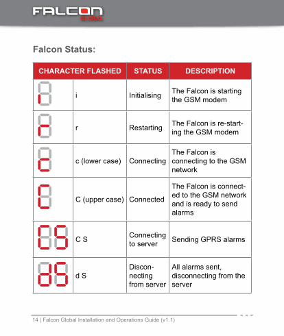
CHARACTER FLASHED STATUS DESCRIPTION
i Initialising The Falcon is starting the GSM modem
r Restarting The Falcon is re-start-ing the GSM modem
c (lower case) ConnectingThe Falcon is connecting to the GSM network
C (upper case) Connected
The Falcon is connect-ed to the GSM network and is ready to send alarms
C S Connecting to server Sending GPRS alarms
d SDiscon-necting from server
All alarms sent, disconnecting from the server
88888888
Falcon Status:
GLOBAL

Falcon Global Installation and Operations Guide (v1.1) | 15
CHARACTER FLASHED STATUS DESCRIPTION
E1 SIM card not found
The Falcon has not detected a SIM card which it has been programmed to use
E2 Reserved Reserved for future use
E4 Connection to Server has failed
The Falcon cannot connect to the server to send the alarms
888888
Falcon Errors
IftheFalcondetectsanerror,itwillflashtheerrorcodeonthesevensegment display.
GLOBAL

16 | Falcon Global Installation and Operations Guide (v1.1)
Diagnostics of Error Codes:
ERROR STATE CAUSE CORRECTIVE ACTION
No SIM cardThere is no SIM card inserted in a SIM holder and the Falcon has been programmed to use that SIM card
OrThe SIM card is damaged
Make sure that a SIM card is correctly inserted in the holderIf there is only one SIM card installed, make sure that the Falcon is not programmed to use the open SIM holder (no SMS or GPRS capabilities on the SIM card
ServerConnectionFail
The Falcon cannot connect to the FSK server to route the GPRS message to the control room
Make sure that the SIM card is capable of connecting to the GPRS networkMake sure that the programming of the Server GPRS settings are correctIf it is a pay as you go SIM card, make sure that it has available funds loaded onto the SIM cardThe GSM network may be experiencing technical problems. Contact the GSM provider
88
88
GLOBAL

Falcon Global Installation and Operations Guide (v1.1) | 17
4. Programming
4.1 On-Board Push Button
The on-board push-button can be used to:• Changetheoperationoftheserialport(selectthealarmpanel).
Refer to section 3.4• SelectProgrammingMode
4.2 PC based Programmer
TheFSKFalconconfigurationsoftwareutilityisaWindows® based programmer which is used as the primary means of programming the Falcon.
The Falcon programmer requires a PC running Windows XP or Windows 7 with an available COM Port (a USB to Serial Adapter can also be used). The FSK USB programming cable is required to program the Falcon (see Appendix B)
To program the unit:• Push and hold down the push button for more than 7 seconds.
GLOBAL
18 | Falcon Global Installation and Operations Guide (v1.1)
88
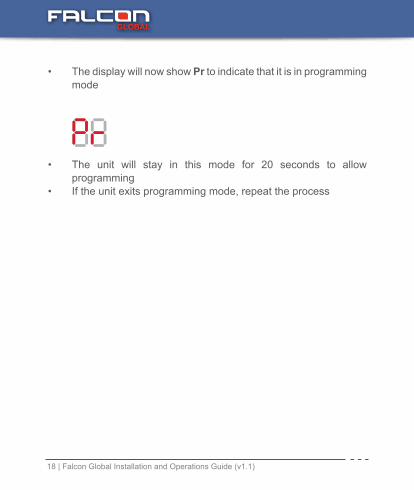
• The display will now show Pr to indicate that it is in programming mode
• The unit will stay in this mode for 20 seconds to allow programming
• If the unit exits programming mode, repeat the process
GLOBAL

Falcon Global Installation and Operations Guide (v1.1) | 19
The Falcon uses a standard interface cable along with an adapter to connect to various alarm panels.
The cable ends are interchangeable.
The following adapter boards are available:
ALARM PANEL ADAPTERRhino No adapterTexecom premier Texecom/IDS (5 pin)IDS Texecom/IDS (5 pin)Paradox Paradox (4 pin)Pima Pima (4 pin)
VERY IMPORTANT: Plug the adaptor board into the Alarm Panel and NOT the Falcon Unit
Appendix A –SERIAL INTERFACE
GLOBAL
NOTE: The DSC uses the ADP-DSC adaptor and not the standard interface cable.

20 | Falcon Global Installation and Operations Guide (v1.1)
Falcon Serial Interface Cable
MOLEX 2510 MOLEX 2510
1 1
WIRES ARE TWISTED TOGETHER
NO
T US
ED
NO
T US
ED
WIRE LENGTH = 3.0m
DATA TO PANEL (GREEN) DATA TO PANEL (BLUE)
GND (BLACK)
4
3
2
1
4
3
2
1
TEXECOM SERIAL INTERFACE
Falcon to Texecom Premier Serial Interface Cable
Use the serial interface cable along with the adapter board marked TEXECOM/IDS
GLOBAL

Falcon Global Installation and Operations Guide (v1.1) | 21
MENU 71 0 - TEL NO 22 (YES)1 - ACC CODE 3456 (YES)2 - PROTOCOL TYPE = 4 (CONTACT ID)3 - DIALER ATTEMPTS = 14 - PARTITION (SELECT PARTITIONS 1 AND 2)5 - SELECT REPORTING OPTIONS
MENU 70 1,2,5,8 ON (ENABLE COMMUNICATOR)MENU 76 OPTION 5 – COM 1 DEVICE TYPE
ENTER ‘3’ – ComIP PROTOCOLOPTION 6 – COM IP ADDRESS/PORT ENTER ‘192 168 001 254 10000’ (spaces for readability)OPTION 8 – COM IP SUBNET MASK ENTER ‘8’
Programming of the Texecom Premier two COM Port Alarm Panel
Program the Falcon to use the Texecom Serial Alarm Interface (Input / Output)
The Falcon is connected to COM1 on the Alarm Panel
The following programming is required on the Texecom panel:
GLOBAL

22 | Falcon Global Installation and Operations Guide (v1.1)
The Falcon can send alarms received from the serial port of the Paradox E65, MG5050 and SP6000 alarm panels.
Plug the adapter marked PARADOX into the serial port on the Paradox alarm panel. Plug the other end into the Falcon serial port.
Events Sent By the Paradox Alarm Panel
The table below shows the Contact ID codes which will be sent in response to the messages received from the Paradox E65/MG5050 and SP6000 alarm panel serial ports.
Uploading and Downloading the Texecom Premier Alarm Panel
The Texecom premier alarm panel can be uploaded and downloaded using the Texecom WinTex software (available at www.texe.com). Please contact the local Texecom agent for more details.
Additional Software is available from FSK Electronics which will be needed to connect to the Alarm Panel (via the Falcon). Please refer the FSK APN USER GUIDE.
PARADOX SERIAL INTERFACE
GLOBAL

Falcon Global Installation and Operations Guide (v1.1) | 23
PARADOX CONTACT IDEVENT GROUP
NOSUB-GROUP NO CON-
TACT ID CODE
EVENT (1)RESTORE (3)
ZONE/USER
06 = Non Reportable Event
00 = Telephone Line Trouble 350 1 0
29 = Arming with User
01 - 32 = User Number 400 3 USER
30 = Special Arming
03 = Partial Arming 456 3 005 = Arm Keyswitch 409 3 9906 = Arm Keyswitch 456 3 0
31 = Disarming with User
01-32 = User Number 401 1 USER
32 = Disarming after Alarm with user
01-32 = User Number 401 1 USER
34 = Special Disarming
N/A 401 1 USER05 = Disarming with Keyswitch 401 1 USER
36=ZoneInAlarm
01to32=ZoneNumber 130 1 ZONE
37 = Fire Alarm 01to32=ZoneNumber 110 1 ZONE
38=ZoneAlarmRestore
01to32=ZoneNumber 130 3 ZONE
40 = Special Alarm
00 = Panic non-medical emergency 120 0
01 = Panic medical 100 1 002 = Panic Fire 110 1 005 = Duress Alarm 120 1 0
42=ZoneTampered
01-32=ZoneNumber 380 1 ZONE
GLOBAL

24 | Falcon Global Installation and Operations Guide (v1.1)
PARADOX CONTACT IDEVENT
GROUP NOSUB-GROUP NO CONTACT
ID CODEEVENT (1)
RESTORE (3)ZONE/USER
44 = New Trouble
01 = AC Failure 301 1 0
02 = Batt Fail 302 1 004 = Bell Current Overload 320 1 0
05 = Bell disconnected 320 1 0
08 = Fail To Communicate Tel 1 350 1 1
09 = Fail to Communicate Tel 2 350 1 2
10 = fail to Communicate Pager 350 3 3
11 = fail to communicate voice 350 3 4
45= Trouble Restore
01 = AC Failure Restore 301 3 0
02 = Batt Fail restore 302 3 004 = Bell Current Overload Rest 320 3 0
46 = Bus/wireless module new trouble
01 = tamper Trouble
137 1 0
48 = Special (Partition 1 only)
01 = Reporting Test 602 1 004 = Installer Entered Prog Mode 627 3 0
05 = Installer Exited Prog Mode 628 1 0
07 = Maintenance Exited Prog Mode
Falcon Global Installation and Operations Guide (v1.1) | 25
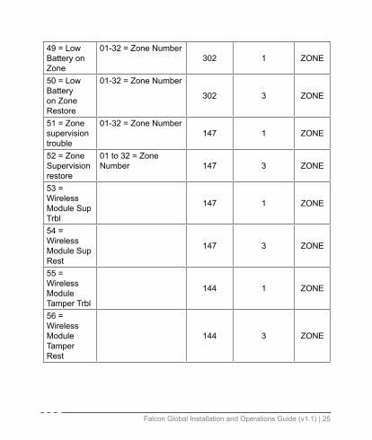
49 = Low Battery on Zone
01-32=ZoneNumber302 1 ZONE
50 = Low Battery onZoneRestore
01-32=ZoneNumber
302 3 ZONE
51=Zonesupervision trouble
01-32=ZoneNumber147 1 ZONE
52=ZoneSupervision restore
01to32=ZoneNumber 147 3 ZONE
53 = Wireless Module Sup Trbl
147 1 ZONE
54 = Wireless Module Sup Rest
147 3 ZONE
55 = Wireless Module Tamper Trbl
144 1 ZONE
56 = Wireless Module Tamper Rest
144 3 ZONE

26 | Falcon Global Installation and Operations Guide (v1.1)
PIMA SERIAL INTERFACE
Plug the adapter marked PIMA into the serial port on the Pima alarm panel. Plug the other end into the Falcon serial port.
The Pima serial interface will send the standard FSK Contact ID alarm codes.
DSC SERIAL INTERFACE
Connect the molex connector ( 4 pin connector) to the serial interface on the Falcon. Wire the other side of the adaptor to the keypad interface of the panel.
GLOBAL

Falcon Global Installation and Operations Guide (v1.1) | 27
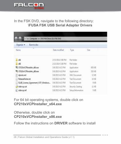
Appendix B –PROGRAMMING CABLE AND SOFTWAREThe Falcon is programmed using the FSK USB Programming Cable and FSK DVD kit which contains the programming software (FSK Item Code 40027) .
Installing the Drivers for the FSK USB to UART Programmer
Install the drivers before plugging the USB Programmer into the computer’s USB port
GLOBAL
28 | Falcon Global Installation and Operations Guide (v1.1)
For 64 bit operating systems, double click onCP210xVCPInstaller_x64.exe
Otherwise, double click onCP210xVCPInstaller_x86.exe
Follow the instructions on DRIVER software to install
In the FSK DVD, navigate to the following directory: \FUSA FSK USB Serial Adapter Drivers
GLOBAL
Falcon Global Installation and Operations Guide (v1.1) | 29
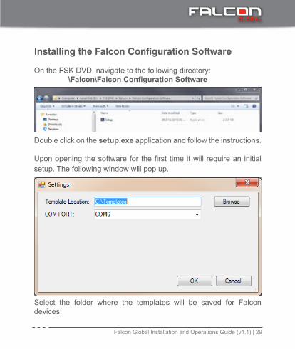
Installing the Falcon Configuration Software
On the FSK DVD, navigate to the following directory: \Falcon\Falcon Configuration Software
Double click on the setup.exe application and follow the instructions.
Uponopeningthesoftwareforthefirsttimeitwillrequireaninitialsetup. The following window will pop up.
Select the folder where the templates will be saved for Falcon devices.
GLOBAL
30 | Falcon Global Installation and Operations Guide (v1.1)
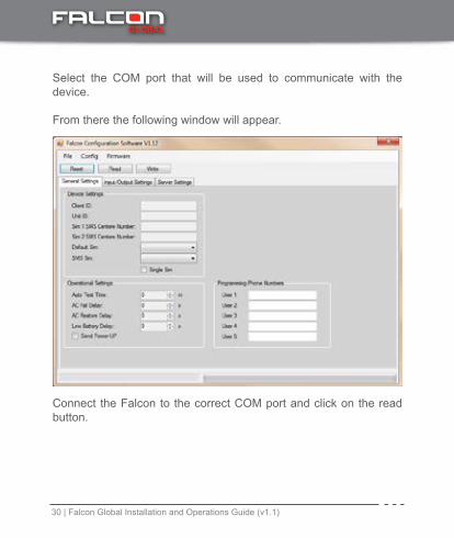
Select the COM port that will be used to communicate with the device.
From there the following window will appear.
Connect the Falcon to the correct COM port and click on the read button.
GLOBAL
Falcon Global Installation and Operations Guide (v1.1) | 31
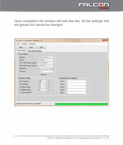
Upon completion the window will look like this. All the settings that are greyed out cannot be changed.
GLOBAL
32 | Falcon Global Installation and Operations Guide (v1.1)
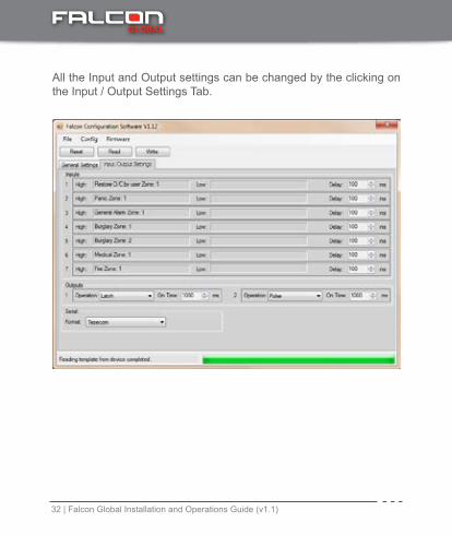
All the Input and Output settings can be changed by the clicking on the Input / Output Settings Tab.
GLOBAL

TROUBLESHOOTING
www.fsk.co.za
14 Richard Road, Industria North, Johannesburg, South Africa
T: +27 (0) 11 477 2600
CALL CENTER: 0861 105 962

NOTES

NOTES

ww
w.fs
k.co
.za14
Ric
hard
Roa
d, In
dust
ria N
orth
Joha
nnes
burg
, Sou
th A
fric
a
T: +2
7 (0
)11
477
2600
E:
sale
s@fs
k.co
.za
Inno
vativ
e te
chno
logy
by F
SK E
lect
roni
cs
CALL
CEN
TER:
086
1 10
5 96
2
FSK1600022 - Falcon Global Manual Cover_v1.indd 2 2016/04/13 2:44 PM