installation, operation, maintenance...note: use correct tools for hvac equipment installation,...
TRANSCRIPT

Modular Water-Cooled Chillers
Installation, Operation, Maintenance
MS010XC, MS015XC, MS020XC, MS030XC, MS040XC, MS050XC, MS070XC, MS085XC
Standard and Total Access™ Modules

2
Contents
Safety Information.....................................................................................................................................................................................3Nameplate and Model Number Nomenclature..............................................................................................................................4Chiller Arrangement and Components, Standard and Total Access™ Modules...............................................................5-7General Data................................................................................................................................................................................................8Shipping Information..........................................................................................................................................................................9-10Clearances and Dimensions............................................................................................................................................................11-16Piping, Flow Protection...........................................................................................................................................................................17Pressure Relief Piping, Water Treatment Specifications, Pipe Flushing.................................................................................18Module Assembly, Standard Modules........................................................................................................................................19-21Module Assembly, Total Access™ Modules......................................................................................................................................22Multiflush Assembly, Leak Testing......................................................................................................................................................23Electrical Installation, Wiring, Electrical Data............................................................................................................................24-28Frame and Enclosure Panel Installation............................................................................................................................................29Installation Checklist................................................................................................................................................................................30Start-Up Data Log...............................................................................................................................................................................31-32Operation...............................................................................................................................................................................................33-34Maintenance.........................................................................................................................................................................................34-36Troubleshooting....................................................................................................................................................................................... 37Daily Log................................................................................................................................................................................................38-39
This Multistack installation and operation manual will assist in the proper installation and operation of Multistack modular chillers. Review this manual carefully.
• The information and illustrations contained in this manual are generalized. Consult with a Multistack representative to address specific installation and operating details not covered in this manual.
• Good electrical and piping practices in accordance with all National and local codes must be followed. • This equipment must not be installed near an open flame per local codes and ASHRAE specifications.• Personnel servicing Multistack modular chillers must have, at minimum, a Class II EPA certification.• Questions regarding the content of this manual and Multistack products should be directed to an authorized Multistack representative or
to the Multistack Service Department at: (608) 366-2400 or via e-mail to [email protected]
Planning AheadTo ensure all warranties and a successful installation, a Factory Authorized Technician is required to perform start-up of the Multistack Chiller. If start-up is to be performed directly by Multistack, a minimum of two weeks notice is required. Please call the Multistack Service Department at (608) 366-2400 to schedule.
Multistack has a policy of continual improvement and reserves the right to change product design, literature and specifications without notice.
© 2016 Multistack
This manual provides information on the proper installation, operation and maintenance requirements for Multistack water-cooled modular chillers. Follow these instructions to help ensure that the chiller performs properly. Failure to follow these in-structions can significantly affect the chiller’s performance and reliability and may adversely affect the equipment warranty.

3
Safety InformationThis manual includes warnings, cautions and notes.
DANGER conveys serious hazards for injury or death.WARNING indicates risk of injury or death.CAUTION warns of possible injury or damage.NOTE calls out work practices that can result in optimal operations.
Warnings, cautions and notes include:DANGER: To avoid the risk of electrical shock, personal injury or death, disconnect all electrical power to the unit before performing any maintenance or service. The unit may have more than one electrical power supply. Assume all electrical wires are live, energized wires. Use lockout/tag outs. DANGER: Use extreme caution when working around electrical components, wiring and connections to avoid injury or death by electric shock.DANGER: Never remove a lockout from equipment unless you placed it there. Each person shall place his/her own lock/tag when required to isolate an energy source. Do not start any adjustment, service or repair without verifying that the tag/lock out switch or control cannot be by-passed or over-ridden. Verify that the locked-out switch or control cannot be overridden. Test the equipment to be certain that the locked-out switch is de-energized and not simply malfunctioning. Press all start buttons to confirm that the equipment WILL NOT start. Confirm that the system being serviced or repaired is the system that has been locked out. Before restarting equipment, verify all tools and other items have been removed, all machine guards are in place, all electric systems are reconnected, and personnel are clear of equipment.DANGER: During installation, testing, servicing and troubleshooting this product, it may be necessary to work with live electrical components. Only qualified licensed electricians or other properly trained persons may perform these tasks. Failure to follow all electrical safety precautions can result in death or serious injury. All HVAC equipment must be installed per the National Electric Code (NEC) and/or all applicable state/local codes.DANGER: Incorrect handling of HVAC equipment can result in explosions, electrical shock or fire, causing property damage, injury and/or fatality. DANGER: HVAC liquids and chemicals can be dangerous if used incorrectly or if spills or accidents occur. Handle detergents and solvents with care to avoid spills and burns. DANGER: Danger of explosion. Refrigerant cylinders can explode causing serious injury and/or death if not handled and stored properly.
WARNING: Only qualified, licensed electricians with proper personal protection equipment should wire Multistack chillers. Injury or death my result if not properly wired due to electric shock hazardWARNING: Danger of electrical shock. Many types of HVAC equipment have switches and regulators with electrical current on even when other parts of the equipment appear to be turned off. Main circuit breakers must be turned off before servicing equipment to avoid injury, fatality.WARNING: Be sure to use lifting slings with lifting capacity to safely handle unit weight. Consult the unit’s as-built submittal drawings for unit weight data. WARNING: If welding on chiller water connections, use proper electrical grounding to avoid damaging the compressors or chiller controls. Never weld directly on the heat exchanger shells. Only an authorized ASME-certified repair agency may weld directly on ASME-certified shells. After weld-ing, an “R” stamp is required.
CAUTION: Working with HVAC equipment can be hazardous due to electricity, moving parts, chemicals, combustion and other hazards. Use safe work habits including proper tools and personal protective equipment. Understand and heed all safety information, installation guidelines and operation and maintenance procedures.CAUTION: Pressurized application of cleaning substances or refrigerants must be done with the correct procedures to ensure the safety of technicians and others, and avoid property damage.
NOTE: Use correct tools for HVAC equipment installation, maintenance and adjustment. Use the correct tools to make tight connections without strip-ping threads or breaking screws and bolts. Use accurate refrigerant and electrical meters to properly maintain and diagnose HVAC equipment.

4
MS 050 X C or N 2 H 1 W 0 A A -410A
SeriesModule Nominal Capacity (10 - 160 tons)
Compressor Type1
AHRI Certified (C - certified, N - Not certified)
Configuration2
Voltage3
Module Number ( 1 - single, 2 - multiple)Application4
AHRI Version - if applicableEvaporator5
Condenser6
Refrigerant
1 B: Bristol, C: Trane Cornerstone, R: Bitzer Screw, S: Trane Scroll, T: Danfoss Turbocor, Z: Copeland scroll (old elec), X: Copeland Scroll (ZP), A: Copeland Scroll (ZR)2 1- Standard, 2- Total Access, 3 - Evap extended headers, 4 - Cond extended headers, 5 - Both extended headers, V - others3 A - 208/3/60, L - 230/3/60, H - 460/3/60, C - 575/3/60, D - 200/3/50, E - 400/3/50, F - 380/3/60, S - 220/230/1/60, V - other4 A - Air Cooled split, C - Single module temp controller, D - Cond unit, F - Fluid cooler (high temp),H - Heat recovery, R - Heat pump, W - Water cooled5 A - Brazed SS, B - Brazed SMO, C- S&T copper, D - S&T cu-Ni, V - Other6 A - Brazed SS, B - Brazed SMO, C- S&T copper, D - S&T cu-Ni, E - Double wall brazed, V - Other
Model Number Nomenclature
Unit NameplateThe chiller nameplate is located on the front of the control panel. Use the unit model number nomenclature to identify specific features and options of an Multistack chiller module.
Multistack Water-Cooled Modular Chillers Multistack invented the modular chiller. Multistack modular chillers are available in a wide range of capacities, and with two independent scroll compressors. Modules can be mix-matched and combined to create up to 15-module arrays and 1,275 tons of cooling capacity using environmentally friendly R-410A. Multistack modular chillers can help owners qualify for USGBC LEED points and significant utility rebates. Multistack’s innovative modular design makes adding more capacity as easy as purchasing and installing more modules.
Total Access™ Modular ChillersWith Total Access, heat exchangers are located on the outer edges of the chiller frame to provide easy serviceability with a small equip-ment room footprint. Total Access options include 10- through 85-ton modular chillers.

5
UnitNameplate
High Pressure Transducer
High VoltagePanel
Isolation/Disconnect Switch
Buss BarDuct
Entering Chilled Water Header
Leaving ChilledWater Header
Evaporator
Filter/Strainers
LeavingCondenser
Water Header
Entering Condenser
Water Header
Scroll Compressors
Condenser Expansion Valve
Liquid Line Sight Glass
Low Pressure Transducer
Low VoltagePanel
Standard Modular Chiller Arrangement
Total Access™ Modular Chiller ArrangementMultistack’s Total Access option makes maintenance and serviceability even easier by placing heat exchangers at the outside of the module frame. Manual isolation valves are factory-installed (Total Access units only) between the heat exchangers and water supply mains for heat exchanger isolation and removal without the need to remove a module or shut down the entire chiller while allowing access to all serviceable components.
High VoltagePanel
High Pressure Transducer
Evaporator
Expansion Valve
Low VoltagePanel Isolation/Disconnect
Switch
Buss BarDuct
CondenserFilter/Strainers
Scroll Compressors
Low Pressure Transducer
Isolation Valve
Condenser

6
Chiller Components
Master Control PanelEach chiller has a master control panel that can be mounted on top of any of the module panels using provided knockouts. Sensors, cables and wiring connect through the bottom of the master control. The master control box includes built-in terminal strip inputs for flow switches, start/stop signal, alarm output, and power phase monitor. As shipped, the Master Control also contains the pLAN communication wire to be field installed by the start-up technician. Four temperature sensors and sensor wells are supplied by Multistack: entering chilled water, leaving chilled water, entering condenser water, and leaving condenser water. The sensors are to be installed in customer’s piping system.
Module Control Boards and Low Voltage PanelThe module control boards communicate individual module temperatures and pressures to the master control. Each module has a switch labeled Auto/ Off/ Manual. Normal operation is in the Auto mode. If there is a problem with the master control, the selector switch can be changed to Manual to provide individual module leaving chilled water temperature control that was pre-set at the master control. Module High Voltage PanelThe high voltage panel contains each compressor’s contactor, circuit breaker, control relay and transformer. External to the panel is the single-module isola-tion switch to isolate the that module from high voltage supply power.
Compressors, Sensors, Switches• Standard modules use two scroll compressors with separate refrigeration
circuits. • Each refrigerant circuit has a high pressure (HP) and low pressure (LP)
transducer that sends pressure signals to the module slave controller board. Each compressor also includes an HP switch with a manual reset button.
• Transducers are a 0-5V ratiometric type. • Compressors include oil level sight glasses. Oil level should be at 1/8 - 1/4
full during operation. • Each circuit has its own leaving chilled water temperature sensor and
refrigerant suction temperature sensor. • Compressor crankcase heaters are not standard on Multistack MS chiller
modules.
Chilled and Condenser Water Connections • Water connections to the chilled and condenser side are standard 6-inch
grooved pipes on MS010X through 070X, and 8-inch on MS085X units. • The upper header on the chilled water side is entering water to the
module. • The bottom header is chilled water leaving the module. • Water entering the condenser is on the bottom. • Water leaving the condenser is on top. • The entering header on both the evaporator and condenser contains a 30-
mesh filter strainer to prevent debris from entering the brazed plate heat exchangers. This strainer should only be used as a final filter stage.
• Proper filtration before the module should be installed for easy access to cleaning, such as a ‘Y’ or a basket type of strainer.
High Voltage Panel
A CompressorIsolation Switch
ControlRelay Transformer
High VoltageCircuit Breaker Control
Relay
B CompressorIsolation Switch
A CompressorContactor
B CompressorContactor
SingleCircuit
Breaker
Master Controller
AUTO/OFF/MANUAL Switch
Module Slave Controller
Low VoltageTerminal Strips
Low VoltageCircuit Breaker
Low Voltage Panel

7
Optional Manual Isolation ValvesStandard modules are not supplied with isolation valves. Manual or electrically actuated valves may be ordered as an option from Multistack. Total Access modules are supplied with manual isolation valves from the factory and may be upgraded to electrically actuated valves as an option. Multistack recommends exercising the isolation valves as part of annual maintenance.
Optional Hot Gas BypassAs an option, hot gas bypass valves (Sporlan HGBE-8) can be provided for each circuit. The valve is adjustable from 75 to 150 psi with a standard setting of 120 psig. A screw on the pilot valve handles the adjustment. Turning clockwise increases the valve setting; counter-clockwise rotation decreases the valve setting.
Hot Gas Bypass Valve
Expansion Valves and Liquid Line Sight Glasses (Standard unit.)
Butterfly Valve Actuator for Variable Flow shown on standard module with extended headers.
Power ActuatedButterfly Valve
Expansion Valve, Subcooling, Liquid Line Sight Glass• Each circuit on a module has a thermal expansion valve located
between the water header pipes on the condenser side. During factory run testing the valves are adjusted to maintain 10-12 degrees superheat. Check the superheat periodically to maintain this range. Subcooling should normally be in a 10-15 degree range. No external subcooler is used.
• The liquid line sight glass shows green on the indicator bulb if no moisture is present in the refrigerant circuit. Yellow indicates potential moisture.
• Sight glasses should show full during normal operation. • Flashing in the sight glass indicates possible under-charge of the
circuit. • Refer to the unit nameplate for refrigerant charge information.
Variable Flow and Power Actuated Butterfly ValvesFor variable flow on the chilled or condenser water side, chiller mod-ules must be ordered with power actuated butterfly valves. Note: The footprint of an array of standard modules will increase as the valves add length. Total Access™ module footprint will not change.
1. Multistack recommends controlling the chiller pumps to maintain pressure differential across the chiller, not the system. Control based on system pressure will provide erratic results.
2. Chiller minimum flow bypass for the system can be programmed in the master controller.
Heat Exchanger Isolation Valves on Total Access™ Modular Chiller
Expansion Valves
Sight Glasses

8
General Data TableMS010X MS015X MS020X MS030X MS040X MS050X MS070X MS085X
Compressor Type Scroll
Dry Weight (lbs. each) 89 135 135 146 280 293 390 419
Normal Capacity (tons each) 5 7.5 10 15 20 25 30 40
Compressor Quantity/Module 2 2 2 2 2 2 2 2
Oil Charge (pints per compressor) 3.5 6.9 6.9 6.9 9.5 9.5 13.3 13.3
Evaporator (Brazed Plate) Brazed Plate
Weight (lbs.) 50 70 70 90 180 180 220 300
Water Storage (gal.) 1.0 1.6 1.6 2.2 5.5 5.5 7.3 10.1
Circuit Configuration Dual Dual Dual Dual Dual Dual Dual Dual
Quantity 1 1 1 1 1 1 1 1
Header System (gal.) 7 7 7 7 7 7 7 14
Condenser Brazed Plate
Weight (lbs. each) 50 80 80 100 200 200 290 340
Water Storage (gal.) 1.1 2.2 2.2 2.9 6.6 6.6 10.1 12.3
Circuit Configuration Dual Dual Dual Dual Dual Dual Dual Dual
Quantity 1 1 1 1 1 1 1 1
Header System (gal.) 7 7 7 7 7 7 7 14
Refrigerant Type R410A
Charge (lbs./circuit) 6.5 6.5 6.5 10 18 20 23 28
Number of Circuits 2 2 2 2 2 2 2 2
Total Water Volume - gal./module 16.1 17.8 17.8 19.1 26.1 26.1 31.4 50.3
Operating Weight (lbs.) 1,490 (1,620) 1,500 (1,630) 1,510 (1,640) 1,610 (1,740) 1,790 (1,920) 1,970 (2,100) 2,060 ( 2,210 ) 2,350 (2,680)
Shipping Weight (lbs.) 1,330 (1,470) 1,340 (1,480) 1,350 (1,490) 1,450 (1,590) 1,630 (1,770) 1,950 (1,990) 1,890 ( 2,060) 2,380 (2,630)
NOTES: Figures in parentheses ( ) apply to Total Access™ configuration chillers. Add 75 lbs. per module if equipped with enclosure panels.
Multistack has a policy of continual improvement and reserves the right to change product design, literature and specifica-tions without notice.

9
Module Shipment Package
Pallet #1 — Typical Cabinetry Package (Optional)1. Top Front Panel 2. Bottom Front Panel 3. Rear Panel/End Panel4. Side End Panel5. Master Controller Top Panel6. Frame Pieces 7. Frame Connectors, Fasteners, Clips & Magnetic Tape
12
3
45
6
7
Pallet #2 — Buss Connections8. Buss bar9. Buss bar insulation
10. Ground strap11. Junction Box leg
8
910
11
NOTE: Before accepting delivery of the Multistack chiller, check the overall condition of the equipment for damage such as broken copper lines, oil leaks, damaged controls and/or electrical component housing, or any major component torn loose from its mounting. If the Multistack modular chiller is damaged during shipping by the transportation company or its agent, the installing contractor MUST promptly file a claim with the transportation company and advise Multistack. Any discrepancy or damage must be noted on the bill of lading.
Multistack has a policy of continual improvement and reserves the right to change product design, literature and specifica-tions without notice.

10
Pallet #3 — Typical Piping & Electrical Package18. Master Controller*19. Junction Box20. Junction Box Cover21. Sensors / Cables22. Junction Box Connector (Throat)23. Power Phase Monitor24. Buss bar Connector
25. Power Phase Monitor Wire26. Buss bar Insulation Overlap27. Phase Monitor Wire28. Buss bar End Caps29. Drain Valves & Fittings30. Module Joining Bolts
31. End Cap for Multiflush system (upper)32. End Caps (evap)33. Couplings
34. Multiflush pipe35. Solenoid for Multiflush system 36. Pipe Stubs37. End Cap Multiflush system (lower)38. Filter Stops39. Pet Cock Valves40. Drain Valves & Fittings41. Sensor Wells42. 30 Mesh Filter Strainer
* May be shipped separately to sales office or job site. ** Shipped inside #19 - Junction Box
18
19
20
21
2223
24
25 2627
28
29
30 31
33 37
33
34
35
3637
39
39 40
41
42
Module on Fork Lift Module on Pallet Jack
Caution: Modules Are Top Heavy
Moving Chiller Modules
Multistack chiller modules MS010 through MS085 may be moved using a fork lift truck, pallet jack or similar equipment. Optional spreader bars for lifting and factory-installed wheels are available from Multistack. Contact your Multistack representative. For unit weights see the table on Page 8 and the job-specific as-built submittal drawings.
Multistack has a policy of continual improvement and reserves the right to change product design, literature and specifica-tions without notice.

11
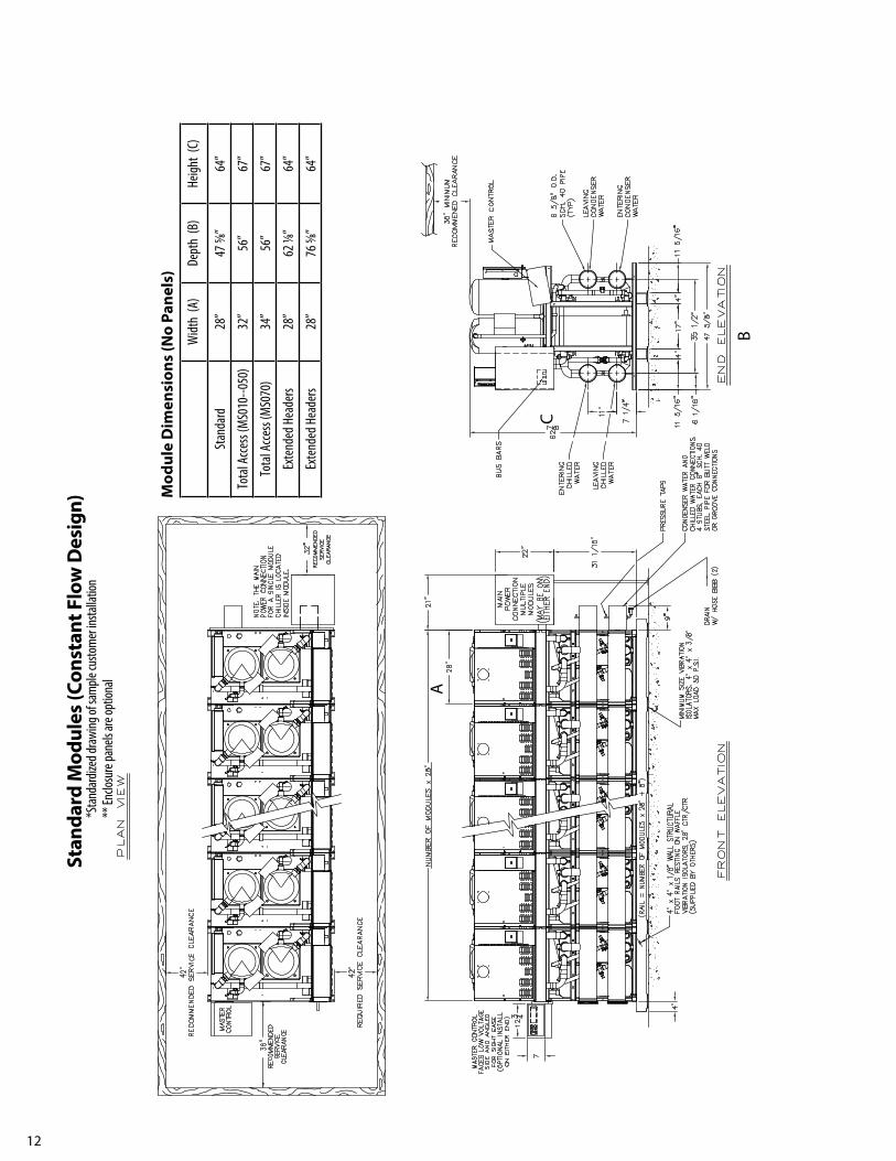
ClearancesDiagram shows typical dimensions and the recommended clearances around the modular chiller. There must be a minimum of six inches clearance over the top of the chiller, including the top of master controller if installed on top of the module.
For specific unit dimensions, refer to as-built submittal drawings.
12
Stan
dard
Mod
ules
(Con
stan
t Flo
w D
esig
n)*S
tanda
rdize
d draw
ing of
sam
ple cu
stom
er ins
tallat
ion**
Enclo
sure
pane
ls are
optio
nal
Mod
ule
Dim
ensi
ons
(No
Pane
ls)
Widt
h (A
)De
pth
(B)
Heigh
t (C
)
Stan
dard
28”
47 5/8
”64
”
Tota
l Acc
ess (
MS0
10--0
50)
32”
56”
67”
Tota
l Acc
ess (
MS0
70)
34”
56”
67”
Exte
nded
Hea
ders
28”
62 1/8
”64
”
Exte
nded
Hea
ders
28”
76 5/8
”64
”
A
B
C

13
Var
iabl
e Fl
ow D
esig
n fo
r Chi
lled
and
Hot
Wat
erSt
anda
rd M
odul
es w
ith E
xten
ded
Hea
ders
on
Evap
orat
ors
and
Cond
ense
rs
Mod
ule
Dim
ensi
ons
(No
Pane
ls)
Widt
h (A
)De
pth
(B)
Heigh
t (C
)
Stan
dard
28”
47 5/8
”64
”
Tota
l Acc
ess (
MS0
10--0
50)
32”
56”
67”
Tota
l Acc
ess (
MS0
70)
34”
56”
67”
Exte
nded
Hea
ders
28”
62 1/8
”64
”
Exte
nded
Hea
ders
28”
76 5/8
”64
”
*Stan
dard
ized d
rawing
of sa
mple
custo
mer
instal
lation
**En
closu
re pa
nels
are op
tiona
l
A
B
C

14
Var
iabl
e Fl
ow D
esig
n fo
r Hot
Wat
er, C
onst
ant F
low
for C
hille
d W
ater
Stan
dard
Mod
ules
with
Ext
ende
d H
eade
rs o
n Co
nden
sers
Mod
ule
Dim
ensi
ons
(No
Pane
ls)
Widt
h (A
)De
pth
(B)
Heigh
t (C
)
Stan
dard
28”
47 5/8
”64
”
Tota
l Acc
ess (
MS0
10--0
50)
32”
56”
67”
Tota
l Acc
ess (
MS0
70)
34”
56”
67”
Exte
nded
Hea
ders
28”
62 1/8
”64
”
Exte
nded
Hea
ders
28”
76 5/8
”64
”
*Stan
dard
ized d
rawing
of sa
mple
custo
mer
instal
lation
** En
closu
re pa
nels
are op
tiona
l
Mod
ule
Dim
ensi
ons
(No
Pane
ls)
Widt
h (A
)De
pth
(B)
Heigh
t (C
)
Stan
dard
28”
47 5/8
”64
”
Tota
l Acc
ess (
MS0
10--0
50)
32”
56”
67”
Tota
l Acc
ess (
MS0
70)
34”
56”
67”
Exte
nded
Hea
ders
28”
62 1/8
”64
”
Exte
nded
Hea
ders
28”
76 5/8
”64
”
B
B
A
C

15
Var
iabl
e Fl
ow D
esig
n fo
r Chi
lled
Wat
er, C
onst
ant F
low
for C
onde
nser
Wat
erSt
anda
rd M
odul
es w
ith E
xten
ded
Hea
ders
on
Evap
orat
ors
Mod
ule
Dim
ensi
ons
(No
Pane
ls)
Widt
h (A
)De
pth
(B)
Heigh
t (C
)
Stan
dard
28”
47 5/8
”64
”
Tota
l Acc
ess (
MS0
10--0
50)
32”
56”
67”
Tota
l Acc
ess (
MS0
70)
34”
56”
67”
Exte
nded
Hea
ders
28”
62 1/8
”64
”
Exte
nded
Hea
ders
28”
76 5/8
”64
”
B
*Stan
dard
ized d
rawing
of sa
mple
custo
mer
instal
lation
** En
closu
re pa
nels
are op
tiona
l
C
A
B

16
Tota
l Acc
ess
Mod
ules
With
or W
ithou
t Var
iabl
e Fl
ow
Mod
ule
Dim
ensi
ons
(No
Pane
ls)
Widt
h (A
)De
pth
(B)
Heigh
t (C
)
Stan
dard
28”
47 5/8
”64
”
Tota
l Acc
ess (
MS0
10--0
50)
32”
56”
67”
Tota
l Acc
ess (
MS0
70)
34”
56”
67”
Exte
nded
Hea
ders
28”
62 1/8
”64
”
Exte
nded
Hea
ders
28”
76 5/8
”64
”
*Stan
dard
ized d
rawing
of sa
mple
custo
mer
instal
lation
** En
closu
re pa
nels
are op
tiona
l
C
B
A

17
Recommended PipingAll piping must be properly and adequately supported at coupling connections and suitable intervals along the piping runs. Hanger design must provide for the weight of fluids in the piping system when the chiller is in operation.
Multistack modules are equipped with brazed plate heat exchangers made of 316 stainless steel. Multistack recommends use of a 30-mesh system strainer, Y-type basket or equal, in each condenser and evaporator inlet header. It is the installing contractor’s responsibility to make sure the water systems have been flushed and the strainers are clean and clear of debris before starting the chiller. Do not flush piping so as to push debris into or through the through the chiller heat exchangers.
Typical Sensor Wells
Important Be sure to install the supplied sensor wells in the system piping. The wells should be installed a few feet from the chiller in the entering and leaving chilled water and entering and leaving condenser water pipes.
Flow ProtectionProof of chilled water and condenser water flow is required by the Master Controller inputs. Paddle-type or Differential Pressure (DP) switches may be used. Switches can be supplied by Multistack as an option, otherwise they are to be field supplied and installed. Chillers purchased with chilled or condenser water pump modules have a DP switch installed across the pump to verify operation. Multistack recommends a paddle-type switch be installed in the leaving chilled water piping using a differential pressure switch. Install it across the inlet and outlet water connections to the chilled and/or condenser water piping connections.
System Water Volume A properly sized chilled water system must have enough time (at least three minutes) to properly control and respond to changes in load and to prevent short cycling of the chiller. To ensure the system water volume is adequate, a general rule of thumb is:
7-10 gallons of water per ton or Acceptable Chilled Water Volume = Chilled Water Design GPM X 3
If the system heat exchangers, piping and components cannot hold the necessary chilled water volume, a properly sized chilled water storage tank should be added.
Condenser Water Temperature Control For installations where entering condenser water temperature could be lower than 65°F Multistack recommends installing a three-way tower bypass valve to maintain a minimum of 65°F entering condenser water temperature. This is based on a 10°F Delta-T system.
CONDENSER SIDE EVAPORATOR SIDE
Items in This Area Included with Chiller
To Cooling Toweror Fluid Cooler
Flow/DPSwitch Isolation
Valves
Sensor Pockets, SensorsSupplied by Multistack,
installed by others.Pressure
Taps
Pressure Taps
Sensor Pockets, SensorsSupplied by Multistack,
installed by others.
IsolationValves
Flow/DPSwitchStrainer
CondenserPump
3-WayBypass Valve
CW In
CW Out
Strainer
Chilled WaterPump
CHW In
CHW Out
Pressure Taps

18
Pipe System Flushing ProcedureBefore connecting the chiller to the condenser and chilled water loop, the piping loops must be flushed with a detergent and hot water (110-130º F) mix-ture to remove any dirt and organic residue. After removing residue, continue flushing with a dilute phosphoric acid, sulfamic acid or citric acid and water mixture to remove inorganic scale in the pipe. Cleaning chemicals such as Nu-Calgon “Imperial Grade” Scale Remover part number 4360-84 or equivalent suitable for both organic residue and scale removal may be substituted. Otherwise detergents and acids shall not be combined unless approved by the chemical manufacturers. Only chemicals compatible with 316 stainless steel, copper and carbon steel shall be used. (Any concentrations of hydrochloric or sulfuric acid or chloride containing chemicals shall not be allowed to come in contact with copper brazed 316 stainless steel heat exchangers).
Caution: The use of unapproved chemicals in the chilled or condenser water supplies may damage the heat exchangers. These chemicals in-clude, but are not limited to, hydrochloric acid, sulfuric acid, muriatic acid, and household bleach. Damage caused by the use of these and other unapproved chemicals is not covered by warranty. The only approved chemicals for heat exchanger cleaning are phosphoric or sulfamic acids in concentrations of 10 percent or less by volume. For more information contact your Multistack representative.
While flushing, 30-mesh Y-strainers (or equivalent) must be in place in the system piping and examined periodically as needed to remove collected residue. The flushing process shall take no less than six hours, or until the strainers are clean after flushing. Old pipe systems with heavy encrustation shall be flushed a minimum of 24 hours and may require as much as 48 hours before the filters run clean. Detergent and acid concentrations shall be used in strict accordance with the respective chemical manufacturers instructions. After flushing with the detergent and/or dilute acid concentrations, the system loop shall be purged with clean water for at least an hour to flush out all residual cleaning chemicals.
Pressure Relief Piping and Refrigerant Monitoring Multistack chiller modules use a small refrigerant charge (typically 0.6 lbs. per ton) and are often exempt from many requirements of ASHRAE 15 Standard. Pressure relief valves are not standard on water-cooled modules and must be special ordered if required by local codes.
Water Treatment / SpecificationsSupply water for both the chilled water and condenser water circuits must be analyzed and treated by a professional water treatment specialist familiar with the operating conditions and construction materials used in Multistack modular chiller heat exchangers, headers and associated piping. Water quality for modular chillers using 316 stainless steel brazed plate heat exchangers and carbon steel headers must be maintained within the following parameters:
Water Specifications Specifications with 25 Percent Glycol ph >7 and <9 ph >7 and <9 Total Dissolved Solids (TDS) Less than 1000 ppm Total Dissolved Solids 1,000 - 10,000 ppm Hardness as CaCO3 30 to 500 ppm Conductivity 1,000 - 15,000 ppm
Alkalinity as CaCO3 30 to 500 ppm Hardness as CaCO3 30 - 500 ppm Chlorides Less than 200 ppm Alkalinity as CaCO3 > 500 ppm Sulfates Less than 200 ppm Chlorides < 200 ppm Sulfates < 200 ppm

19
Module AssemblyMultistack chiller modules and multiple module chiller arrays are designed to be mounted on steel rails.
1. Determine the entering and leaving evaporator and condenser connection arrangement before setting mounting rails and mod-ules modules in place. Connections may be at the same end or opposite ends, depending upon jobsite requirements.
2. Chiller modules are to be mounted on 4- x 4- x 4-inch steel rails or equivalent , 21 inches center-to-center.
3. Place 4- x 4- x 3/8-inch waffle type vibration pads every 22 inches under rails. 50 PSI maximum loading.
Note: Seismic restraint information available from Multistack.
Same End
Opposite End
Vibration Pads
4. Lubricate rails with vegetable shortening or other non-petroleum lubricant to facilitate installation.

20
Module Assembly
5. Place first module on the rails. 6. Slide module into position.
7. Place subsequent modules onto rails. 8. Leave sufficient space between modules to install coupling gaskets.
9. Lubricate gaskets with solid vegetable shortening or other non-petroleum based lubricant.
10. Slide modules together lining up footing holes. Install bottom joining bolts.
11. Install top joining bolts.12. Starting with the lower header, install pipe couplings. Position cou-pling bolts at one and seven o’clock positions as shown for proper frame installation. Note: Assure proper strainer placement.

21
Module Assembly
13. If adjustment is needed when tightening bolts, loosen the center header bolt.
14. The grooved heat exchanger couplings may also be loosened if adjustment is required.
15. Install the header blank ends, starting at bottom, then move to the top blank that includes drain valves (evaporator shown).
16. Install filter stop rings on module closest to piping take-off. The 9-inch long pipe stubs supplied by Multistack are to be installed at the take-off ends of the chiller.
A
B
17. The 3/4-inch drain valve (A), should be located on bottom header and petcock valve (B) installed in each contractor pipe stub.

22
Module Assembly - Total Access™ Modules
Evaporator side view of Multistack Total Access™ modules. (Optional enclosure panels not shown.)
Multistack Total Access modular chillers are assembled into chiller arrays in the same manner as non-Total Access modules as shown on Pgs. 19-21.
Grooved flange water connections on Total Access chiller modules joined into a chiller array.
Condenser side view of Total Access chiller modules assem-bled into a chiller array. .

23
NOTE: See Pallet #3 for Multiflush components, Page 10.
1. Attach Multiflush pipe to module header pipe. 2. Insert 30-mesh filter into header.
3. Install large grooved pipe couplings. Leave loose - do not tighten. 4. Attach Multiflush pipe fittings using grooved couplings as shown.
5. Install manual or solenoid valve at end of Multiflush header.6. Tighten all fittings.
Multiflush System AssemblyThe following procedure describes installation of the Multiflush automatic debris removal system. This system is used periodically to remove dirt and debris from the from the chiller heat exchangers.
Leak Testing
After all piping connections are complete, make a static leak pressure test and seal any leaks. When the leak test has proved satisfactory, start the chiller system pumps and purge any air from the system. Seal any remaining leaks before proceeding.
NOTE: Before leak testing make sure the four sensor wells have been installed.

24
Electrical Installation Field wiring must comply with all federal, state and local regulations. Circuit breakers, fuses, wiring and wire size must be installed per the National Electric Code (NEC). Voltage applied to Multistack chillers must be within plus/minus 10 percent of nameplate voltage. Voltage imbalance between phases may not exceed two percent. According to NEMA Standard MG-1-1998, a two percent voltage imbalance will cause a current imbalance of six to 10 times the voltage imbalance. Voltage imbalance between electrical phases must be kept to a minimum. Most Multistack chillers come with a single point of electrical connection (up to 500 amps) to simplify installation. The main electrical conduit feeding the power junction box may enter from either the top, bottom, or left side of the panel when facing the panel. Chillers requiring more than 500 amps will have multiple electrical connection points (per the 500 amp requirement).
Optional Single Module Field ConnectionFor single module installations, the power junction box can be deleted, but a power phase monitor must be installed. The main electrical feed can connect directly to the module circuit breaker.
Junction Box Support Electrical Junction Box Junction Box Support Leg
1. Attach the electrical junction box support. Line up the orange posts to ensure support is not backwards. The threaded plate slides in between frame.2. The electrical junction box may be installed on either end of the chiller module.3. Remove cover plate on appropriate end of the junction box, then bolt junction box to the support. 4. Cut the junction box support leg to length and fasten to the bottom of box and then to the floor, if necessary.5. Three-phase wire and the ground wire, sized according to the nameplate rating, should be run through the junction box.
Buss bar Installation
NOTE: Contact the local Multistack representative before installing the buss bar. Depending on the start-up representative’s policy, the attachment of the buss bar system, and power phase monitor to the electrician’s wire and lugs may be the responsibility of the electrician or the Multistack autho-rized start-up technician.
1. Remove the buss duct covers. 2. Remove the isolation switch cover
NOTE: There is a dedicated chiller ground in this panel that must connect to a true earth ground.
DANGER: To avoid the risk of electrical shock, personal injury or death, disconnect all electrical power to the unit before performing any mainte-nance or service. The unit may have more than one electrical power supply. Assume all electrical wires are live, energized wires. Use lockout/tagouts.

25
3. Install the three buss bar connector wires to the isolation switch at each module. The wires are shipped with each module.
4. Remove the orange insulation and install the buss bar for Line 3 (back). Connect lug for Line 3 on each module.
5. After connecting the Line 3 lugs for all modules, cut the orange insulation to fit between the lugs. Install the lug cover and snap the buss bar into the plastic holders.
6. Single-phase power for the modules should be taken off two lines of the buss bar. Multistack recommends using Lines 1 and 3.
7. Follow the procedure in Step 5 to complete installation of Lines 1 and 2.
8. Follow the procedure in Step 5 to complete installation of Lines 1 and 2.
9. With all three lines installed, use the provided overlap pieces to cover any open buss bar areas.
DANGER: During installation, testing, servicing and troubleshooting this product, it may be necessary to work with live electrical components. Only qualified licensed electricians or other properly trained persons may perform these tasks. Failure to follow all electrical safety precautions can result in death or serious injury. All HVAC equipment must be installed per National Electric Code (NEC) and all applicable state/local codes.

26
10. The ground bar must be drilled, then attached to the module ground lug.11. Reinstall the buss duct and isolation switch covers. Install the main power connectors as shown. NOTE: IT IS THE ELECTRICIAN’S RESPONSIBILITY TO CONNECT MAIN POWER TO THIS CONNECTOR.
12. Install the power phase monitor as shown. When correctly installed the lettering on the power phase monitor is inverted. Wires are run to the normally open contact of the power phase monitor and connect to the master control.
DANGER: To avoid the risk of electrical shock, personal injury or death, disconnect all electrical power to the unit before performing any maintenance or service. The unit may have more than one electrical power supply. Assume all electrical wires are live, energized wires. Use lockout/tagouts.
Module wiring connections to the power junction box must be completed by a qualified electrician.
NOTE: Be sure to replace all protective covers after completing wiring connections.
On water cooled chillers with single point power, optional wire whips may be ordered and substituted for the standard buss bar. The conduit, wiring and junction box are shipped as part of the loose parts package. The wire and conduit are then connected to the junction box as the modules are installed. Each wire and circuit breaker is marked for correct connection.
Single Point Power
Each wire and circuit breaker is marked for correct connection.

27
Typical Interconnecting Wiring. Consult the Specific, As-Built Submittal Wiring Diagrams
Multistack has a policy of continual improvement and reserves the right to change product design, literature and specifica-tions without notice.
DANGER: To avoid the risk of electrical shock, personal injury or death, disconnect all electrical power to the unit before performing any maintenance or service. The unit may have more than one electrical power supply. Assume all electrical wires are live, energized wires. Use lockout/tagouts.

28
VOLTAGE 208 230 460 575
MS010X* 13.1/136 11.8/136 5.9/66.1 4.7/55.3MS015X 24.8/240 22.4/240 11.9/130 9.1/93.7MS020X 28.1/240 25.4/240 13.9/140 10.7/107.6MS030X 49.8/340 45.0/340 22.5/173 18.0/132MS040X 54.0/538 49.0/538 23.5/229 19.5/180MS050X 67.0/605 60.0/605 30.0/272 24.0/215MS070X 89.0/599 80.0/599 40.0/310 32.0/239MS085X 112.8/943 102.0/943 51.0/408 37.6/375
MCA 3 CONDUCTORS1 CONDUIT
6 CONDUCTORS2 CONDUIT
50 8 —65 6 —85 4 —100 3 —115 2 —130 1 —150 1/0 —175 2/0 —200 3/0 —230 4/0 —255 250 MCM —285 300 MCM 1/0300 — 1/0350 — 2/0400 — 3/0460 — 4/0500 — 250 MCM
System Wire & Fuse Sizing SpecificationsCompressor Rated Load Amps (RLA) and Locked Rotor Amps (LRA) Data
Standard and Total Access™ Modules RLA/LRA
1. Wiring Sizing: Minimum Circuit Ampacity (MCA) MCA = (1.25 x RLA1*) + RLA2 + RLA3 2. Fuse Sizing: Maximum Fuse (MF), Type RK5 Fuse
MF= (2.25 x RLA1*) + RLA2 + RLA3 Where MF does not equal a standard size fuse, the next larger size fuse should be used.
NOTES:A. *RLA1 = RLA of the largest compressor in the system. RLA2 & RLA3 = RLA of the other compres-
sors in the system.B. Total system Minimum Circuit Ampacity (MCA) shall not exceed 500A.C. Wire sizing is based on the National Electrical Code (NEC) rating for 75°C copper wire, with 3
wires per conduit.D. Wiring distance from branch circuit shall not exceed 100 feet.
* MS010X units are also available for single-phase power (230/1/60 )applications and have an RLA of 19.5 amps and LRA of 178 amps.
DANGER: To avoid the risk of electrical shock, personal injury or death, disconnect all electrical power to the unit before performing any maintenance or service. The unit may have more than one electrical power supply. Assume all electrical wires are live, energized wires. Use lockout/tagouts.
(Applicable codes may require different wire sizing)

29
Frame & Panel InstallationAttachment of the optional enclosure panels is the responsibility of the Multistack authorized start-up technician. Typical installation is shown.
1. Install panel clips and spindle posts on the outside four corners of module frame.
2. Attach panel supports on outside of end modules. 3. Attach front frame section on module (33-1/8 -inch pieces on bottom). Use “T” connectors in front middle. The four corner connectors go on top, front and rear.
4. Install two long frames over spindle posts vertically in rear (buss bar side). Attach top frames to corner joints (use special frames with seven holes for end modules only). At-tach 20-inch horizontal frames, two in front, one in rear.
5. Once the frame is assembled, attach the black fasteners and magnetic tape (or Velcro™ strips) to front of support panels.
6. With the first module frame and panels complete, install the additional enclosures.

30
INSTALLATION CHECKLIST & REQUEST FOR AUTHORIZED START-UP ENGINEER
CUSTOMER: _______________________________________
JOB NAME: ________________________________________
JOB LOCATION: _____________________________________
CUSTOMER ORDER NO.: ________________________________
CHILLED WATER Yes No N/APiping complete and connected to Multistack Units. q q qWater system filled and vented. q q qPumps installed (Rotation checked). q q qRecommended strainers installed. q q qControls (3-way valves & by-pass valves, etc.) operable. q q qWater system operated and flow balanced to meet unit design requirements. q q qStrainers checked for unusual debris. q q qFlow or differential pressure switch installed. q q q
CONDENSER WATER Yes No N/APiping complete and connected to Multistack Units. q q qCooling tower flushed, filled and vented. q q qPumps installed (Rotation checked). q q qRecommended strainers installed. q q qControls (3-way valves and by-pass valves, etc.) operable. q q qCooling tower fans wired and operable. q q qCondenser water system operated. q q qCondenser & evaporator strainers must be checked, cleaned and free of debris. q q qFlow or differential pressure switch installed. q q q
ELECTRICAL Yes No N/APower wiring complete and in accordance with nameplate rating on Multistack unit and prepared for connec-tion in accordance with installation manual.
q q q
NOTE: No power is to be applied to unit prior to inspection by Multistack engineer.All interlock wiring complete between control panel and complies with Multistack specifications and with applicable codes.
q q q
MISCELLANEOUS Yes No N/AThermometer wells, thermometer gauges, control, etc. installed. q q qA minimum system load of 50% of total building load is available for testing and adjusting controls.
q q q
We understand that authorized representatives of the installing electrical and piping contractor must be available during the start-up period and that coordination is our responsibility.We further understand that the services of Multistack Authorized Start-up Engineer will be furnished for a period of not more than sixteen (16) consecutive normal working hours and we agree that a charge for time and expenses will be made by Multistack if services are required for longer than sixteen (16) consecutive normal working hours or if repeat calls are required through no fault of Multistack.
Signed Title
Company Name, Company Location and Company Telephone
Job Location Telephone

31
START-UP DATA LOG
START-UP DATE: _______________________________ SHIP DATE: _____________________________JOB NAME: _________________________________JOB NUMBER: _____________________________ADDRESS:_________________________________________________________________MULTISTACK REPRESENTATIVE: ____________________________________________________MODEL NUMBER: ____________________________________________________________
MODULE SERIAL NUMBERS 1. ____________________ 7. _______________________ 2. ____________________ 8. _______________________ 3. ____________________ 9. _______________________ 4. ____________________ 10. _______________________ 5. ____________________ 11. _______________________ 6. ____________________ 12. _______________________
WATER SIDE AND INSTALLATION CHECKLIST CIRCLE CORRECT RESPONSE 1. Chiller mounted on rails and isolators? YES NO 2. Any visible damage, oil or refrigerant leaks? YES NO
If yes, detail: ________________________________________3. All pipe work independently supported from chiller? YES NO 4. System sensor wells installed: CHILLED: IN OUT CONDENSER: IN OUT5. Flow or differential switches installed: CHILLED: ____ CONDENSER: ____6. Operation of flow or differential switches with reduction of 50%. P __________8. Condenser 3-way by-pass valve? YES NO If yes, Temperature set point: _____ °F9. System strainers installed? CONDENSER: YES NO
EVAPORATOR : YES NO10. Install System sensors and apply thermal paste? YES NO
ELECTRICAL AND CONTROLS CHECKLIST1. All electrical connections tight and correct? YES NO2. Power wiring sufficient to carry F.L.A.? YES NO3. Voltage levels: PHASES: 1 + 2 _______ 2 + 3 ________ 1 + G _______ 2 + G ________ 3 + G ________4. Set module board addresses, run communication wire, do factory reset on Master Control? YES NO 5. Program system variable to site connections, date and time? YES NO 6. Verify demand for cooling? YES NO7. Check temperature and pressure sensors through microprocessor display? YES NO8. Check interlock operation: Stop chilled water pump? YES NO Stop condenser water pump? YES NO9. Provide training to contractor or owner? YES NO9. Leave system in full operation? YES NO10. Notify contractor of any problems? YES NO
Start-up Service Technician Owner or Contractor Acceptance
DESIGN PARAMETERS1. ECHW ____________________2. LCHW ____________________3. CHW GPM ____________________4. CHW P DROP ____________________5. ECW ____________________6. LCW ____________________7. CW GPM ____________________8. CW P DROP ____________________

32
Start-Up Data Log, Cont’d
MODULE CURRENT TEMPERATURE
HP LPA B C Suct LoChw SYS LCHW ECHW
1AB
2AB
3AB
4AB
5AB
6AB
7AB
8AB
9AB
10AB
11AB
12AB
Actual Setpoints1. ECHW (Upset) ____________________2. LCHW (Loset) ____________________3. VSP __________________________4. Control ________________________5. TDIFF _________________________6. Flush Dur. ______________________*PC0 Program Version _________________(Go to main menu screens then push PRG & UP but-tons)
Measured Readings1. CHW P Drop _____________________2. CW P Drop ______________________
Factory Setup1. Program Type __________________
2. Chiller Type ___________________
3. Refrigerant ___________________
4. Flow Faults: CHW ________________
CW _________________
5. Circuit Type ___________________
6. Variable Flow __________________
A. Valve Display ________________
B. CHW Output _________________
C. CHW Bypass _________________
D. CHW Min Output ______________
E. CW Output __________________
F. CW Bypass __________________
G. CW Set point_________________
H. CW Min Output _______________
I. CW PID ____________________
J. CHW PID ___________________

33
OperationThe Multistack chiller provides chilled water to an external load, based on return water temperature to the Multistack Master Control. When the entering chilled water temperature sensor sends a signal to the master controller that cooling is needed, compressors will start and begin to produce chilled water. A compressor start is determined by the entering chilled water (ECHW) upper set point and the variable set point setting in the Master Control System Variables menu. When the ECHW sensor senses that the chilled water temperature has dropped below the set point, compressors will begin to cycle off.
Chiller modules equipped with modulating butterfly valves on the chilled water side are controlled from the leaving chilled water set point (lower set point) in the System Variables menu. The module slave board(s) send a 2-10 VDC output to each actuator to modulate the water valve to maintain lower set point. When a module is not running, valves close to prevent bypassing water at the operating chiller modules.
For variable flow applications one or more valves may remain open at all times to provide minimum flow through the chiller. The valve that stays open will always be the lead compressor for that day, eliminating the need for an external bypass installed at the chiller. If modulating butterfly valves are used on the condenser side of each module, the valves will control to a discharge pressure setting selected from the Factory Setup menu. This is also a 2-10 VDC output each module board sends to the valve actuator. If the condenser pump cycles off while no modules are running, minimum flow doesn’t need to be considered. If the condenser pump runs at minimum flow, the condenser bypass should be enabled in the Factory Setup menu.
Sequence of Operation, Leaving Chilled Water Temperature ControlThe Multistack chiller is equipped with a microprocessor based supply water temperature controller. The chiller operates in response to leaving chilled water (LCHW) set points.
AUTO (Toggle switch on machine)In AUTO mode, the compressors operate as needed to maintain the LCHW set point. Cooling temperature control with CONTROL TO: set to LEAVING is based on: LCHW SET POINT
LCHW OFFSET LCHW STAGE OFF1. The Leaving Chilled Water (LCHW) set point default is 45 degrees F with a 35 to 80 degree ranges. The controller maintains this value within __ +/- of
the LCHW Offset.2. The LCHW Offset default is 2 degrees F with a range of 0.5 to 10 degrees. This is the value above and below the LCHW Set point that compressors are
staged on and off. 3. The LCHW Stage Off delay is defaulted to 30 seconds with a 5 to 180 second range. This allows for a delay between the shutting off of compressors in
Leaving Chilled Water control. If the system leaving temperature drops too far too quickly (2 degrees below where the previous compressor was to shut off) the controls will allow one more compressor to shut off within that 30 seconds. That should be enough to back off the leaving temperature so the over shoot condition doesn’t continue.
Modulating valves on the modules will control to the following in AUTO MODE:
The SYSTEM VARIABLE of CONTROL TO: Set to a value of LEAVING.Evaporator valve will control to the LCHW SET POINT.
Variable Flow Chilled Water and/or Variable Flow Condenser WaterMotorized actuating valves for varying water flow through the evaporators and or condensers are factory installed on each heat exchanger. To accomplish VFD chilled water and/or condenser water flow the system must control the chilled water pump and/or condenser water pump based on pressure drop across the chiller. As a compressor starts a valve is opened and pressure drop decreases. The pump should then speed up to match the desired pressure drop. Control of the pump is external to the chiller. Additionally, the chilled water loop must have a minimum flow bypass at the end of the loop (by others) to maintain minimum flow through the chiller.
The valves on a Multistack chiller are dual purpose. First, a user defined number of valves can be programed to remain open at all times as a minimum flow bypass through the chiller. This is selectable at the master controller or through the BAS with an optional web-portal. Second, the motorized valves modulate to maintain leaving chilled water temperature control out of each heat exchanger. The bypass valve(s) will follow the lead compressor and remain locked in a bypass position and rotate with the lead compressor. Remaining valves will open when corresponding compressors start. The compres-sor will then modulate for leaving water temperature control. Valves close when corresponding compressors shut off. When there is no demand for cooling all valves are closed with only the pre-selected number of bypass valves remaining open for a minimum flow chiller bypass.
If all evaporators and condensers are equipped with variable flow valves the master controller, in conjunction with each corresponding slave controller, will modulate the valves for simultaneous leaving chilled water and condenser head pressure control from each heat exchanger (with the exception of the heat exchanger(s) programmed as the minimum flow chiller bypass).

34
Factory Setup/CommissioningGo to the System Variables Menu and select Factory Settings to access the program type and other setup information. Setup is to be done by the Multistack authorized startup technician. Setup parameters are factory set to default values. Jobsite conditions must be configured at startup. To change these set-tings requires a password that is available to authorized service technicians by calling Multistack at (608-366-2400).
The Standard Program should be used on applications where no glycol is used in the chilled water side. In this mode the chilled water temperature cutout is set at 34°F.
The Low Temperature Program should only be used in applications that have a minimum of 25 percent glycol in the chilled water loop. Cutout on low water temperature in this mode is 20°F and the suction temperature cutout setting (with R-410A refrigerant) is set at 15°F.
Condenser Water Set-Point: If power-actuated butterfly valves are used on the condenser side, this value should be set for the desired discharge pressure. Depending on the condenser water inlet temperature this will adjust the valve to maintain the desired pressure.
Variable Flow: Select ENABLE if doing variable flow on the chilled or condenser side. If not, select DISABLE. To do variable flow, water control valves must be installed on each module between the water header pipe and heat exchanger.
Bypass: Select ENABLE to leave the valve on the lead module open for minimum flow bypass. Select CHILLED WATER or CONDENSER WATER bypass. If no valves are installed on the module keep this variable in the DISABLE MODE.
For information on basic control setup of the modules see the Multistack Comput 600 User manual.
Pressure ReadingsThe operating suction and discharge pressures in the system are directly related to water flow, condenser temperature, chilled water set-point, and system cleanliness. Standard operating conditions with 95°F leaving condenser water and 45°F leaving chilled water temperature are discharge pressure at 325 psig ( 102°F saturated) and suction pressure at 114 psig (38°F saturated).
All water-cooled modules have a high pressure (HP) cutout safety device and a backup HP cutout switch. The HP cutout is 475 psig for a standard water-cooled module with R-410A.Each module also includes a low pressure (LP) safety cutout. The LP cutout is set in the module program at 50 psig.
If circuits are experiencing HP faults first check to see that the cooling tower fan is operating. Next, verify proper water flow to the brazed plate heat exchanger and confirm the strainer and filters are clean and free flowing.
A LP fault is an indication of low refrigerant charge in the system. If a circuit trips out on a LP fault check the static pressure of the system while the circuit is in the off mode. If pressures are low, check the circuit for possible leaks. The circuit can be pressurized to 15 psig with refrigerant and topped to 160 psig with dry Nitrogen.
MaintenanceUse proper safety equiment, tools and procedures when operating and servicing this equipment. Be sure to review all safety warnings, cautions and notes found on Pg. 3 of this manual.
Preventive MaintenanceMultistack publication MAINT-002-0416 provides heat exchanger preventative maintenance guidelines. Contact your Multistack representative for more information. Multistack water cooled chillers, especially those with brazed plate heat exchangers, require careful control of the chilled and condensing water circuits to prevent heat exchanger fouling. Refer to Multistack publication MAINT-001-0416 for water sample collection information.
DANGER: To avoid the risk of electrical shock, personal injury or death, disconnect all electrical power to the unit before performing any maintenance or service. The unit may have more than one electrical power supply. Assume all electrical wires are live, energized wires. Use lockout/tagouts.

35
Strainer Cleaning, Heat Exchanger CleaningAll Multistack modules have a 30-mesh filter strainer in the condenser and evaporator inlet headers. The purpose of the strainer is to prevent debris from entering the heat exchanger. An external “Y” or basket type system strainer should also be installed as a pre-filter to the Multistack strainers. There is no pre-determined time for cleaning the strainer cartridges. The frequency of this process is dependant on the water quality in the condenser and/or evaporator loop. Normally, debris in a water loop is takes the path of least resistance and accumulates in the last modules to receive water.
Multistack modules include the Multiflush automatic blow down system installed on the condenser side of the last module in the chiller array. The Multiflush system is controlled by a timer in the Master Control and opens once a day to remove debris from the loop. Multiflush does not eliminate the need to pull and clean the strainers, but reduces the frequency.
The effect of debris buildup in the condenser water inlet filter cartridge will create nuisance HP (high pressure) faults. By checking the pressure differential between the inlet and outlet of the condensers, it can be determined if the strainers are contaminated. Refer to the MS 010-085X Product Data Catalog for correct pressure drop of your model. For an MS070X module with a 10° F Delta T, the condenser side pressure drop should be 17’ / 7.4 psi; for chilled water 16’ / 7 psi. To keep HP faults from repeating, the strainers will need to be pulled and cleaned. If HP faults still occur after cleaning the strainer cartridges the condenser pump should be checked for proper flow. If flow is not a problem the heat exchangers may need to be cleaned. Refer to Multistack Heat Exchanger Cleaning Bulletin (MAINT-003-0416). Use this procedure to remove and clean the filter cartridges on the condenser side.
1. Turn off the chiller, shut down the condenser pump, and close the butterfly/gate valves to the condenser.2. Drain the water remaining in the condensers and header pipes by opening the drain valve in the pipe stubs or by removing the end grooved fitting cap
on the Multiflush system.3. Remove the first filter in the Multiflush and remove all remaining filters in the bottom condenser header pipes. 4. Slowly open the top butterfly / gate valve, allowing water to flow through the condensers and onto the floor for approximately 30 seconds. This will
push out any debris trapped in the bottom of the heat exchanger as the filters are removed.5. Clean the filters with a hose, power washer, or wire brush as needed and re-install. Slide filters in until contacting the filter stop ring on the first
module. Keep an extra set of strainers for quick re-installation. These filters are available for purchase through Multistack representatives.6. Close the system by installing any grooved fitting clamps previously removed.7. Open the 1/4-inch petcock bleed valves on the pipe stubs.8. Fill the system by opening the bottom butterfly/gate valve and filling from the bottom up. Close the 1/4-inch petcock valves and open the top
butterfly/gate valve after air has been bled from the system.9. Start the condenser pump. Bleed any remaining air in the system once the pump has started and start the chiller.
If circuits trip out on Low Suction Temperature, or Low Chilled Water Temperature, check the chilled water inlet filter cartridge. The strainers are located in the top header on the chilled water side. The previous instructions on condenser strainer removal do not need to be exactly followed. If the strainers are clean the fault may be caused by a low flow condition or a low set point in the Master Control. If these possibilities are eliminated the evaporator heat exchangers may need cleaning.
Compressor Oil LevelAll compressors on water-cooled modules have an oil level sight glass on each compressor. Each module is run tested and the oil level is set at the factory. R-410A scroll compressors are single stage and oil level is set at 1/8 – 1/4 full sight glass. The compressor uses POE oil. Use Copeland type 998-E022 or Nu Calgon 32-3MA. Call Multistack service at (608)366-2400 for factory oil charge for each compressor.
Refrigerant Charge / EvacuationAll water-cooled modules are factory charged to recommended refrigerant volumes. Prior to charging, each circuit is evacuated to 150 microns and held 15 minutes. The proper refrigerant charge for each module can be found on the module data plate. For proper charge on water-cooled modules, the circuit should be charged until the sight glass clears. Model Refrigerant Lbs. Per Circuit Oil Charge Per Circuit (in Pints)*MS010X 8 3.5MS015X 8 6.9MS020X 8 6.9MS030X 12 6.9 MS040X 15 9.5 MS050X 18 9.5MS070X 24 13.3MS085X 28 13.3* Based on Copeland compressors

36
Filter DriersMultistack modules contain very short piping runs to the major components. Only a micro refrigerant charge (0.6 lbs. per ton) is used, and all circuits are evacuated to 150 microns. For this reason a liquid line filter drier is not factory installed in the unit. When changing a major component in the system, a replaceable core suction line filter kit can be added to reduce contamination. The suction filter kit can be purchased from Multistack through your local representative.
Superheat/SubcoolingSubcooling is necessary in the system to prevent flash gas as the refrigerant enters the expansion valve. Multistack uses a mechanical-type expansion valve on all modules. Clockwise adjustment of the valve increases superheat. On water-cooled modules, superheat is set at 10°-12°F during the factory run test. Multistack condensers are sized so that liquid refrigerant subcooling occurs without a separate subcooler. The general range of subcooling is 10°-20°F.
Daily Log SheetLog sheets foud at the back of this manual can be used daily, weekly or as desired to record operation characteristics of the chiller. The information recorded on the log sheet can also help diagnose potential system problems.
Annual Maintenance DANGER: To avoid the risk of electrical shock, personal injury or death, disconnect all electrical power to the unit before performing any maintenance or service. The unit may have more than one electrical power supply. Assume all electrical wires are live, energized wires. Use lockout/tagouts.
Annual maintenance requirements for Multistack Chillers involve proper shut-down of the machine and cleaning of the heat exchangers. The Preventative Maintenance bulletin (MAINT-002-0416) and Heat Exchanger Cleaning bulletin (MAINT-003-0416) describe the recommended procedures for both processes. Multistack makes available the 151A Cleaning Kit to assist with this process. Refer to the 151A Cleaning Kit bulletin for more details. Also check annually:
• All electrical components (contactors, fuses, relays, etc.) to identify any signs of excessive wear. Check for tight connections. • Superheat, pressure gauges, oil levels, Master Controller condition, and sensor accuracy should also be checked.• Exercise all isolation valves, manual or power operated.
CompressorsIn the event of a compressor failure, determine the cause. A motor burn due to a fault in the motor insulation is quite rare. Most burnouts are actually caused by a mechanical condition or lubrication problem. In the event of a burnout, proper clean up procedures should be followed.
1. Check all electrical components of the circuit (contactors, fuses, wires, etc.)2. If necessary do a system clean up. Nu-Calgon RX-11 flush, or Sporlan System Cleaner work well.3. Install a suction filter drier with burnout core. 4. Evacuate the system to a minimum of 500 microns and hold for 20 minutes.5. Charge the circuit with virgin refrigerant. Charge with liquid into the discharge side. See proper refrigerant charge on nameplate data of unit.6. Run the system 2-3 weeks with burnout filter core. Replace with standard core drier
Heat Exchanger CleaningMultistack publication MAINT-003-0416 provides procedures for cleaning heat exchangers. Contact your Multistack representative for more information.

37
Fault Solution Fault Solution
No Display on Master Module
• Check main disconnect for power• Check circuit breakers in module• Check transformer in modules• Check for 24V at J1 on board
100% Demand, chiller won’t load
• Turn chiller on• Check sensors• Check load limit setting in system variables
Excessive Cycling
• Check VSP setting is system variables• Check entering CHW sensor location• Look for system problem (low water Volume,
low load)EX 1,2, Interlock
• Check appropriate interlock component• Check jumpers on TB11 in master control
EX 4 Interlock• Check for proper rotation, phasing• Check PPM device
High Discharge Pressure (HP)• Check strainers in condenser headers• Check condenser water flow
Waiting For Chilled Water Flow
• Check CHW pump• Check flow switch operation• Check filter strainers• Check TB11 inputs #3 - #7
Low Suction Pressure (LP)• Check refrigerant charge / leaks• Check expansion valve
Low Suction Temperature• Check suction sensor• Check set-points in system variables• Check for flow restriction
Waiting For Condenser Water Flow
• Check CW pump• Check flow switch operation• Check filter strainers• Check TB11 inputs #3 - #8
Communication Error• Check settings in system variables• Check cables at J11 comm ports• Check dip switch settings
Low Chilled Water Temp• Check LCHW sensor• Check set-points in system variables• Check for flow restriction
Circuit Fault• Check components in control circuit• Check wire crimps in control circuit• Check ratio of HP to LP
No Demand• Check entering CHW sensor• Check set-points in system variables• Check sensor location
P Lan Error• Check cables at J11 comm ports• Check for possible power issues
100% Demand all the time• Check entering CHW sensor• Check set-points in system
variables
Troubleshooting Multistack modular chillers use the Carel PCO3 master control. A user manual for the PCO3 controller is supplied with the submittal package. The user manual details the different status screens and explanations of system or module faults. Use the following guide to troubleshoot modules and the PC03 controller.

38
lllMULTISTACK Chiller Daily Log Sheet
Job Name:
Job Number:
Module Serial Numbers:
Date:
Status Suct. Press Head Press Suct. Temp LoChw Temp Fault (if any)Comp #1Comp #2Comp #3Comp #4Comp #5Comp #6Comp #7Comp #8Comp #9Comp #10Comp # 11Comp #12
SystemEnt. Chw Lvg. Chw Ent CW Lvg. CW Demand Capacity
SystemUpset Loset VSP Load Limit Tdiff Index
Comments:
CHW P Drop CW P Drop

39
lllMULTISTACK Chiller Daily Log Sheet
Job Name:
Job Number:
Module Serial Numbers:
Date:
Status Suct. Press Head Press Suct. Temp LoChw Temp Fault (if any)Comp #1Comp #2Comp #3Comp #4Comp #5Comp #6Comp #7Comp #8Comp #9Comp #10Comp # 11Comp #12
SystemEnt. Chw Lvg. Chw Ent CW Lvg. CW Demand Capacity
SystemUpset Loset VSP Load Limit Tdiff Index
Comments:
CHW P Drop CW P Drop

MS-IOM-001 0317Supersedes MS-IOM-001 0117
FWB
1065 Maple Avenue P.O. Box 510 Sparta, WI 54656Phone 608-366-2400 • [email protected]
www.multistack.com