installation, operation and maintenance …webmedia.greenheck.com/iomuser/iom/460945 ert erch rev 3...
TRANSCRIPT

RECEIVING AND HANDLINGThe ERT/ERCH is thoroughly inspected and test run at the factory. However, damage may
occur during shipping and handling. Upon delivery, inspect the unit for both obvious and hidden damage. If damage is found, record all necessary information on the bill of lading and file a claim with the final carrier. In addition, ensure all accessory items are present. Some accessory items
are stored inside the unit during shipping.
SAFETY WARNINGImproper installation, adjustment, alteration, service or maintenance can cause property damage,
injury or death. Read this installation, operation, and maintenance manual thoroughly before installing or servicing this equipment. Installation and service must be performed by a qualified
installer, service agency, or the gas supplier.
PART #460945READ AND SAVE THESE INSTRUCTIONS
®
ENERGY RECOVERY UNITWITH TEMPERING
Models: ERT-52, 58, 64 & 74 ERCH-20, 45, 55 & 90
INSTALLATION, OPERATION AND MAINTENANCE MANUAL
INSTALLATION SUPPLEMENTS
Refer to the following installation supplements
ERCH supplied with Indirect Gas (IG) heating:Model PVF, Indirect Gas Fired Furnaces for Energy Recovery Units, Part #461006
ERT Curb Assembly Instruction, Part #457157
ERCH Curb Assembly Instruction, Part #460922
SAVE THIS MANUALThis manual is the property of the owner, and is required for future maintenance. This manual should
remain with each ERT/ERCH unit when the job is complete.

�
TABLE OF CONTENTSStorage and Basic Operation . . . . . . . . . . . . . .� Installation . . . . . . . . . . . . . . . . . . . . . . . . . . . . . .3
Lifting . . . . . . . . . . . . . . . . . . . . . . . . . . . . . . . . .3 Unit Weights & Recommended Roof Openings . . . . . . . . . . . . . . . . . . . . . . . . . . . .3 Roof Curb Mounting . . . . . . . . . . . . . . . . . . . . .4 Rail Mounting . . . . . . . . . . . . . . . . . . . . . . . . . . .5 Ductwork Connections . . . . . . . . . . . . . . . . . . .5 Electrical Information . . . . . . . . . . . . . . . . . . . 6-7 Service Clearances . . . . . . . . . . . . . . . . . . . . 8-9 Dimensional Data/Access Door Description .10 Coil Applications & Drain Trap Info . . . . . . 11-1�Optional Accessories . . . . . . . . . . . . . . . . . 13-�4 Electric Heater Application/Operation . . . . . .13 Frost Control Application/Operation . . . . . . . .14 Economizer Application/Operation . . . . . . . . .15 Variable Frequency Drives . . . . . . . . . . . . 16-17 Typical Wiring Diagram . . . . . . . . . . . . . . . . . .18 Sensors and Lights . . . . . . . . . . . . . . . . . . 19-�0 Remote Control Panel & Wiring . . . . . . . . �1-�3
Sensors Mounted by Factory . . . . . . . . . . . . .�4Start-Up Checklist Unit . . . . . . . . . . . . . . . . . . . . . . . . . . . . . . . �5-�6 Optional Accessories . . . . . . . . . . . . . . . . . . . .�7 Fan . . . . . . . . . . . . . . . . . . . . . . . . . . . . . . . �8-30 Energy Recovery Wheel . . . . . . . . . . . . . . . . .31 Routine Maintenance Checklist . . . . . . . . . . .3� Belts and Motors . . . . . . . . . . . . . . . . . . . . . . .33 Blower Wheel and Fasteners . . . . . . . . . . . . .33 Bearings and Filters . . . . . . . . . . . . . . . . . . 34-35 Coil Maintenance . . . . . . . . . . . . . . . . . . . . . . .35 Energy Recovery Wheel Maintenance . . 36-37 Accessing Energy Recovery Wheel . . . . . . . .36 Removing Wheel Segments . . . . . . . . . . . . . .36 Cleaning Wheel Segments . . . . . . . . . . . . . . .37Parts List . . . . . . . . . . . . . . . . . . . . . . . . . . . . . .38Sequence of Operation . . . . . . . . . . . . . . . . . .39Troubleshooting Airflow . . . . . . . . . . . . . . . . .40Unit Troubleshooting . . . . . . . . . . . . . . . . . 41-4�Notes . . . . . . . . . . . . . . . . . . . . . . . . . . . . . . . . . .43Warranty . . . . . . . . . . . . . . . . . . . . . . . . Backcover
STORAGEWhen a unit is not going to be in service for an extended amount of time, certain procedures should be followed to keep the fans in proper operating condition .
• Rotate fan wheel monthly and purge grease from bearings once every three months • Cover unit with tarp to protect from dirt and moisture (Note: do not use a black tarp as this will promote condensation) • Energize fan motor once every three months • Store belts flat to keep them from warping and stretching • Store unit in location which does not have vibration • After storage period, purge grease from fan bearings before putting fan into service
If storage of unit is in a humid, dusty or corrosive atmosphere, rotate the fan and purge the bearings once a month . Improper storage which results in damage to the unit or components will void the warranty .
BASIC OPERATIONThe ERCH and ERT units bring in fresh, outdoor air and remove stale, exhaust air . Prior to discharging the exhaust air, the energy recovery wheel transfers energy from the exhaust air to the outdoor air at an efficiency of 70-80% . Simply put, this unit preconditions the outdoor air to save money on heating and cooling costs . These particular units also have cooling and heating options available after the recovery wheel to further condition the fresh air temperature if desired .
Exhaust Air discharged
outside
Energy Recovery Wheel Exhaust Air from building
Optional Heater
Conditioned Air sent to spaceOptional Cooling Coil
OutdoorAir

3
INSTALLATIONThe system design and installation should follow accepted industry practice, such as described in the ASHRAE Handbook .
Adequate space should be left around the unit for piping coils and drains, filter replacement, and maintenance . Sufficient space should be provided on the side of the unit for routine service and component removal should that become necessary .
See Service Clearances/Access Panel Locations section for more details .
LIFTING 1) Before lifting, be sure that all shipping material has been
removed from unit . �) To assist in determining rigging requirements, weights are
shown below . 3) Unit must be lifted by all lifting lugs provided on base
structure . 4) Rigger to use suitable mating hardware to attach to unit
lifting lugs . 5) Spreader bar(s) must span the unit to prevent damage to the
cabinet by the lift cables . 6) Always test-lift the unit to check for proper balance and
rigging before hoisting to desired location . 7) Never lift units by weatherhoods . 8) Never lift units in windy conditions . 9) Preparation of curb and roof openings should be completed
prior to lifting unit to the roof .10) Check to be sure that gasketing has been applied to the
curb prior to lifting the unit and setting on curb .11) Do not use fork lifts for handling unit .
Lift using lifting lugs and spreader bar
UNIT WEIGHTS & RECOMMENDED ROOF OPENING
SUPPLYDISCHARGE
EXHAUSTINTAKE
U
V
0.500.50
SAFETY WARNINGAll factory provided lifting lugs must
be used when lifting the units . Failure to comply with this safety precaution
could result in property damage, serious injury, or death .
All dimensions shown are in inches .Unit weights assume outdoor configuration with weatherhoods, filters, outdoor air damper, and a 6-row chilled water coil (wet weight) .
•The ERCH units also include an indirect gas fired furnace .•The ERT units also include a 3-row wrap around heatpipe and a 1-row hot water coil (wet weight) .
Position the unit roof opening such that the supply discharge and exhaust inlet of the unit will line up with the corresponding ductwork . Be sure to allow for the recommended service clearances when positioning opening (see Service Clearances) . Do not face the outdoor air intake of the unit into prevailing wind and keep the intake away from any other exhaust fans . Likewise, position the exhaust discharge opening away from outdoor air intakes of any other equipment .
When cutting only duct openings, cut opening 1 inch (�5mm) larger than duct size to allow clearance for installation . Area enclosed by roof curb must comply with clearance to combustible materials . If the roof is constructed of combustible materials, area within the roof curb must be ventilated, left open, or covered with non-combustible material which has an “R” value of at least 5 . If area within curb is open, higher radiated sound levels may result .
Where the supply or warm air duct passes thru a combustible roof, a clearance of one inch must be maintained between the outside edges of the duct and combustible material in accordance with NFPA Standard 90A .
UnitSize
Approx. Weight (lbs)
U VUnitSize
Approx. Weight (lbs)
U V
ERT-52 3590 55 45 ERCH-20 1640 46 37
ERT-58 5110 60 48 ERCH-45 �750 54 39
ERT-64 5440 60 48 ERCH-55 3�00 65 47
ERT-74 8180 75 50 ERCH-90 5��0 85 49

4
Rooftop units require curbs to be mounted first . The duct connections must be located so they will be clear of structural members of the building .
1. Factory Supplied Roof Curbs Roof curbs are Model GKD, which are shipped in a knockdown kit (includes duct adapter) and require field assembly (by others) . Assembly instructions are included with the curb .
2. Install Curb Locate curb over roof opening and fasten in place . (Refer to Recommended Roof Openings) . Check that the diagonal dimensions are within ±1/8 inch of each other and adjust as necessary . For proper coil drainage and unit operation, it is important that the installation be level . Shim as required to level .
3. Install Ductwork Installation of all ducts should be done in accordance with SMACNA and AMCA guidelines . Duct adapter provided to support ducts prior to setting the unit .
4. Set the Unit Lift unit to a point directly above the curb and duct openings . Guide unit while lowering to align with duct openings . Roof curbs fit inside the unit base . Make sure the unit is properly seated on the curb and is level .
LW
All dimensions shown are in inches .Weights are for 1� inch high curbs .
Curb Outside Dimensions
Roof curb details, includingduct location dimensions, are
available on ERT and ERCH roof curb assembly instructions.
Part #457157 and Part #460922, respectively.
ROOF CURB
SIDE OF UNIT
BASE
1 INCH INSULATION
E
D
C
A
B
Curb Outside Dimensions and Curb Weights (lbs)
Model L W Weight Model L W Weight
ERT-52 154 .5 65 .5 535 ERCH-20 93 51 �80
ERT-58 180 74 .75 705 ERCH-45 100 .5 60 .63 355
ERT-64 180 74 .75 705 ERCH-55 11� .75 71 .5 450
ERT-74 195 9� .75 935 ERCH-90 1�5 .75 90 .75 6�5
ModelCurb Cap Dimensions
A B C D E
ERT-52 � .00 4 .00 3 .00 1 .00 0 .75
ERT-58 � .00 4 .00 3 .00 1 .00 0 .75
ERT-64 � .00 4 .00 3 .00 1 .00 0 .75
ERT-74 � .00 6 .�5 5 .�5 1 .375 0 .50
ERCH-20 � .00 � .00 1 .00 0 .88 0 .75
ERCH-45 � .00 4 .�5 � .00 1 .31 0 .50
ERCH-55 � .00 4 .�5 � .00 1 .31 0 .50
ERCH-90 � .00 4 .�5 � .00 1 .31 0 .50
All dimensions shown are in inches .Curb Cap Details for Factory Supplied Roof Curbs
ROOF CURB MOUNTING

5
1 FanWheelDia.
1 FanWheelDia.
Rotation
Rotation
Rota
tion
Rota
tion Length of Straight Duct
GOOD
POOR
GOODPOOR
GOOD POOR
Turning Vanes
Turning Vanes
SYSTEM EFFECT FACTOR CURVES
FPM X 100OUTLET VELOCITY
0 5 10 15 20 25 30 35 40 45
1.2
1.0
0.8
0.6
0.4
0.2
0.0
STA
TIC
PR
ES
SU
RE
LO
SS
CURVE 1
CURVE 2
CURVE 3
CURVE 4
1 FanWheelDia.
1 FanWheelDia.
Rotation
Rotation
Rota
tion
Rota
tion Length of Straight Duct
GOOD
POOR
GOODPOOR
GOOD POOR
Turning Vanes
Turning Vanes
SYSTEM EFFECT FACTOR CURVES
FPM X 100OUTLET VELOCITY
0 5 10 15 20 25 30 35 40 45
1.2
1.0
0.8
0.6
0.4
0.2
0.0
STA
TIC
PR
ES
SU
RE
LO
SS
CURVE 1
CURVE 2
CURVE 3
CURVE 4
DUCTWORK CONNECTIONSExamples of good and poor fan-to-duct connections are shown below . Airflow out of the fan should be directed straight or curve the same direction as the fan wheel rotates . Poor duct installation will result in low airflow and other system effects .
Rail Layout• Rails designed to handle the weight of the ERT/ERCH should be
positioned as shown on the diagram (rails by others) .• Make sure that rail positioning does not interfere with the supply
air discharge opening or the exhaust air intake opening on the ERT/ERCH unit . (Avoid area dimensioned “B” below) .
• Rails should run the width of the unit and extend beyond the unit a minimum of 1� inches on each side .
• Set unit on rails .
AB
SUPPLY/EXHAUSTOPENING
OUTDOOR
AIR
INTAKE
HOOD
AB
SUPPLY/EXHAUSTOPENING
OUTDOOR
AIR
INTAKE
HOOD
Isometric view of unit on rails
Side view of unit on rails
All dimensions shown are in inches .• Recommended duct sizes are based on velocities across the cfm range of each model at approximately 800 feet per minute (FPM) at
minimum airflow and up to 1600 fpm at maximum airflow . Recommended duct sizes are only intended to be a guide and may not satisfy the requirements of the project . Refer to plans for appropriate job specific duct size and/or velocity limitations .
• Straight duct lengths were calculated based on 100% effective duct length requirements as prescribed in AMCA Publication �01 . Calculated values have been rounded up to nearest foot .
OUTDOOR AIR WEATHERHOOD Outdoor air weatherhood will be factory mounted .
EXHAUST WEATHERHOOD The exhaust weatherhood is shipped separately as a kit with its own instructions .
DAMPERS Backdraft dampers are always included as an integral part of the exhaust hood assemblies . Motorized outdoor air and exhaust air dampers are optional and are factory mounted (and wired) at the intake .
RAIL MOUNTING
Recommended Discharge Duct Size and Length
Model ERT Model ERCH
Model Blower Size Duct Size Straight Duct Length Model Blower Size Duct Size Straight Duct Length
ERT-52 18 �0 x �0 48 ERCH-20 9 14 x14 36
ERT-58 �0 �� x �� 60 ERCH-45 1� �0 x �0 48
ERT-64 �� �4 x �4 60 ERCH-55 15 �8 x �8 60
ERT-74 �7 �9 x �9 72 ERCH-90 18 3� x 3� 60
ModelRail
Mounting ModelRail
Mounting
A B A B
ERT-52 4 .75 41 .�5 ERCH-20 5 .1 �5 .0
ERT-58 6 .75 47 .1�5 ERCH-45 7 .1 �5 .1
ERT-64 6 .75 47 .1�5 ERCH-55 5 .7 35 .0
ERT-74 �7 .75 64 .�5 ERCH-90 6 .6 36 .1All dimensions shown are in inches .

6
ELECTRICAL INFORMATIONThe unit must be electrically grounded in accordance with the current National Electrical Code, ANSI/NFPA No . 70 . In Canada, use current C .S .A . Standard C�� .1, Canadian Electrical Code, Part 1 . In addition, the installer should be aware of any local ordinances or electrical company requirements that might apply . System power wiring must be properly fused and conform to the local and national electrical codes . System power wiring is to the unit main disconnect (door interlocking disconnect switch standard on most units) or distribution block and must be compatible with the ratings on the nameplate: supply power voltage, phase, and amperage (Minimum Circuit Amps - MCA, Maximum Overcurrent Protection - MOP) . All wiring beyond this point has been done by the manufacturer and cannot be modified without affecting the unit’s agency / safety certification .
If field installing an additional disconnect switch, it is recommended that there is at least four feet of service room between the switch and system access panels . When providing or replacing fuses in a fusible disconnect, use dual element time delay fuses and size according to the rating plate .
If power supply is desired thru bottom of unit, run the wiring through the curb, cut a hole in the cabinet bottom, and wire to the disconnect switch . Seal penetration in cabinet bottom to prevent leakage .
The electric supply to the unit must meet stringent requirements for the system to operate properly . Voltage supply and voltage imbalance between phases should be within the following tolerances . If the power is not within these voltage tolerances, contact the power company prior to operating the system .
Voltage Supply - See voltage use range on the rating plate . Measure and record each supply leg voltage at all line disconnect switches . Readings must fall within the allowable range on the rating plate .
Voltage Imbalance - In a 3-phase system, excessive voltage imbalance between phases will cause motors to overheat and eventually fail . Maximum allowable imbalance is �% . To determine voltage imbalance, use recorded voltage measurements in this formula .
Key: V1, V�, V3 = line voltages as measured
VA (average) = (V1 + V� + V3) / 3
VD = Line voltage (V1, V� or V3) that deviates farthest from average (VA)
Formula: % Voltage Imbalance = [100 x (VA-VD)] / VA
Most factory supplied electrical components are pre-wired . To determine what electrical accessories require additional field wiring, refer to the unit specific wiring diagram located on the inside of the unit control center access door . The low voltage control circuit is �4 Vac and control wiring should not exceed 0 .75 ohms . Refer to Field Control Wiring Length/Gauge table for wire length maximums for a given wire gauge . Control wires should not be run inside the same conduit as that carrying the supply power . Make sure that field supplied conduit does not interfere with access panel operation .
CAUTIONIf any of the original wire as supplied with the appliance must be replaced, it must be
replaced with wiring material having a temperature rating of at least 105ºC.
WARNINGTo prevent injury or death due to
electrocution or contact with moving parts, lock disconnect switch open.
WARNINGFor units with a gas furnace, if you turn off the
power supply, turn off the gas.
Field Control Wiring Length/GaugeTotal Wire Length Minimum Wire Gauge
1�5 ft . 18
�00 ft . 16
300 ft . 14
450 ft . 1�
If wire resistance exceeds 0 .75 ohms, an industrial-style, plug-in relay should be added to the unit control center and wired in place of the remote switch (typically between terminal blocks R and G on the terminal strip (refer to Typical Control Center Components) . The relay must be rated for at least 5 amps and have a �4 Vac coil . Failure to comply with these guidelines may cause motor starters to “chatter” or not pull in which can cause contactor failures and/or motor failures .
Note: Standardfactoryinstalledelectricpost-heatershavetheirowndisconnectseparatefromtheunitdisconnect.Thus,eachelectricpost-heaterrequiresitsownseparatepowerconnection.

7
1 . Main Disconnect (non-fusible, lockable) � . Motor Starter - Exhaust Air Fan 3 . Motor Starter - Outdoor Air Fan 4 . Motor Contactor - Energy Wheel 5 . �4 VAC Control Transformer 6 . �4 VAC Terminal strip 7 . Fuses for blower motors
TYPICAL CONTROL CENTER COMPONENTS
1
� 3 4
7
5
Exploded Detail of Terminal Strip
6
Model ERCH Model ERT
Access to Control Center Components is gained through the access panel indicated.
ERT-58ERT-64
ERT-52ERT-74

8
WH
EE
L C
AS
SE
TT
E2
INC
H F
ILT
ER
S
EXHAUST AIR
SECTIONCOIL
ELECTRICALBOX
ERT-52 INTAKE
TOP VIEW
2 IN
CH
FIL
TE
RS
CA
SS
ET
TE
SLI
DE
OU
T
*64 in.
36 in.
ELECTRICALBOX
ERT-58 & 64
36 in.
36 in.
**36 in.
WH
EE
L C
AS
SE
TT
E2
INC
H F
ILT
ER
S
EXHAUST AIR
SECTIONCOIL
ELECTRICAL
INTAKE
TOP VIEW
BOX
2 IN
CH
FIL
TE
RS
60 in.
48 in.
48 in.
48 in.
Clearances for service and component removal on ERT-5�, ERT-58 and ERT-64 * Clearance for energy wheel removal on ERT-5� only** Clearance for energy wheel service on ERT-58 and ERT-64
ERT-52ERT-58ERT-64
Clearances for service and component removal on ERT-74
ERT-5�, 58, 64 and 74 units require minimum clearances for access on all sides for routine maintenance . Filter replacement, drain pan inspection and cleaning, energy wheel cassette inspection, fan bearing lubrication and belt adjustment are examples of routine maintenance that must be performed . Blower and motor assemblies, energy recovery wheel cassette, coil and filter sections are always provided with a service door or panel for proper component access . Clearances for component removal may be greater than the service clearances, refer to drawings for these dimensions .
ERT-74
SERVICE CLEARANCES / ACCESS PANEL LOCATIONS FOR MODEL ERT

9
SERVICE CLEARANCES / ACCESS PANEL LOCATIONS FOR MODEL ERCH
ERCH-�0, 45, 55, and 90 units require minimum clearances for access on all sides for routine maintenance . Filter replacement, drain pan inspection and cleaning, energy wheel cassette inspection, fan bearing lubrication and belt adjustment are examples of routine maintenance that must be performed . Blower and motor assemblies, energy recovery wheel cassette, coil and filter sections are always provided with a service door or panel for proper component access . Clearances for component removal may be greater than the service clearances, refer to drawings for these dimensions .
ERCH-20ERCH-45
ERCH-55ERCH-90
Clearances for service and component removal on ERCH-�0 and ERCH-45 * Clearance for energy wheel removal on ERCH-�0** Clearance for energy wheel removal on ERCH-45
Clearances for service and component removal on ERCH-55 and ERCH-90
Whe
el C
asse
tte
2 in
. filt
ers
2 in
. filt
ers
CoilSection
Exhaust AirIntake
Electrical Box
Access Panel
Access Panel
Acc
ess
Pan
el
Acc
ess
Pan
el
Acc
ess
Pan
el
Cassette
Slid
es Out
52 in.Clearance with
IG Heater
0 in.Clearance without
IG Heater
ExhaustHood
Out
do
or
Air
Ho
od
IG H
eate
r
*48 in. **64 in.
36 in.
36 in.
TOP VIEW
Whe
el C
asse
tte
2 in
. filt
ers
2 in
. filt
ers
CoilSection
Exhaust AirIntake
Electrical Box
Access Panel
Access Panel
Acc
ess
Pan
el
Acc
ess
Pan
el
Acc
ess
Pan
el
52 in.Clearance with
IG Heater
0 in.Clearance without
IG Heater
ExhaustHood
Out
do
or
Air
Ho
od
IG H
eate
r
42 in.
42 in.
42 in.
TOP VIEW

10
DIMENSIONAL DATA / ACCESS DOOR DESCRIPTIONS AND LOCATIONS
1) Exhaust blower, motor, and drives�) Aluminum mesh filters (intake hood)3) Energy recovery wheel, motor, belt, and seals Outdoor air filters Outdoor air intake damper (optional)
Electric preheater (optional) Frost control sensors (optional) Economizer sensors (optional)3a) ERT-5� wheel access4) Coil access5a) Outdoor air blower, motor, and drives
(with indirect gas furnace)
5b) Outdoor air blower, motor, and drives (without indirect gas furnace)
6) Control center All electrical controls VFDs for blowers (optional) VFD for energy recovery wheel (optional)6a) Same items shown in 6, but for ERT-5� & 746b) Same items shown in 6, but for ERT-58 & 647) Exhaust air filters Exhaust air intake damper (optional)8) Electric post-heater control center (optional)9) Bypass damper (optional)
ModelExterior Dimensions
A B C D E F G H I
ERT-52 158 66 69 18 41 �1 .5 9 �5 �3 .5
ERT-58 184 70 79 16 59 .5 6 .5 19 .�5 �9 �5 .�5
ERT-64 184 75 79 16 59 .5 1� .375 �0 �9 �5 .�5
ERT-74 199 91 97 18 78 8 .75 19 35 �7 .375
ERCH-20 98 50 56 18 �8 .5 17 6 14 .�5 18
ERCH-45 106 69 66 16 41 �3 .375 10 .5 13 .375 �0
ERCH-55 118 70 76 16 59 .5 5 .875 7 .1�5 �1 .�5 �5
ERCH-90 131 85 96 16 78 � .875 10 �4 .5 �7
ModelOverall Exterior Dimensions
Width (including Lifting Lugs)
Overall Width (with Exhaust Hood)
Overall Length (with Outdoor Air Hood)
ERT-52 7� .375 96 176
ERT-58 8� .375 106 �00
ERT-64 8� .375 106 �00
ERT-74 100 1�5 .75 �17
ERCH-20 59 .5 75 116
ERCH-45 69 .5 86 1��
ERCH-55 79 .5 101 134
ERCH-90 99 .5 1�3 147
All dimensions shown are in inches .
All dimensions shown are in inches .
Model ERCH
A
I
C
B
D
E
F
G
H
A
I
C
B
D
E
F
G
H
Model ERT
Following is a list of items accessible through the access doors shown on the diagrams . Some items are optional and may not have been provided .
7
6b
1�
3
3a
45b
6a
7
1 �
3
4
5a
5b6
8
8
9
11
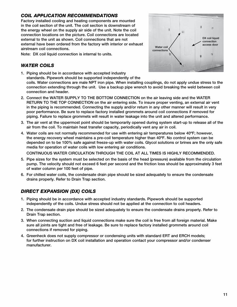
COIL APPLICATION RECOMMENDATIONS Factory installed cooling and heating components are mounted in the coil section of the unit . The coil section is downstream of the energy wheel on the supply air side of the unit . Note the coil connection locations on the picture . Coil connections are located external to the unit as shown . Coil connections that are not external have been ordered from the factory with interior or exhaust airstream coil connections . Note: DX coil liquid connection is internal to units .
WATER COILS
1 . Piping should be in accordance with accepted industry standards . Pipework should be supported independently of the coils . Water connections are male NPT iron pipe . When installing couplings, do not apply undue stress to the connection extending through the unit . Use a backup pipe wrench to avoid breaking the weld between coil connection and header .
� . Connect the WATER SUPPLy TO THE BOTTOM CONNECTION on the air leaving side and the WATER RETURN TO THE TOP CONNECTION on the air entering side . To insure proper venting, an external air vent in the piping is recommended . Connecting the supply and/or return in any other manner will result in very poor performance . Be sure to replace factory installed grommets around coil connections if removed for piping . Failure to replace grommets will result in water leakage into the unit and altered performance .
3 . The air vent at the uppermost point should be temporarily opened during system start-up to release all of the air from the coil . To maintain heat transfer capacity, periodically vent any air in coil .
4 . Water coils are not normally recommended for use with entering air temperatures below 40ºF; however, the energy recovery wheel maintains a pre-coil temperature higher than 40ºF . No control system can be depended on to be 100% safe against freeze-up with water coils . Glycol solutions or brines are the only safe media for operation of water coils with low entering air conditions .
CONTINUOUS WATER CIRCULATION THROUGH THE COIL AT ALL TIMES IS HIGHLy RECOMMENDED .
5 . Pipe sizes for the system must be selected on the basis of the head (pressure) available from the circulation pump . The velocity should not exceed 6 feet per second and the friction loss should be approximately 3 feet of water column per 100 feet of pipe .
6 . For chilled water coils, the condensate drain pipe should be sized adequately to ensure the condensate drains properly . Refer to Drain Trap section .
DIRECT EXPANSION (DX) COILS
1 . Piping should be in accordance with accepted industry standards . Pipework should be supported independently of the coils . Undue stress should not be applied at the connection to coil headers .
� . The condensate drain pipe should be sized adequately to ensure the condensate drains properly . Refer to Drain Trap section .
3 . When connecting suction and liquid connections make sure the coil is free from all foreign material . Make sure all joints are tight and free of leakage . Be sure to replace factory installed grommets around coil connections if removed for piping .
4 . Greenheck does not supply compressor or condensing units with standard ERT and ERCH models; for further instruction on DX coil installation and operation contact your compressor and/or condenser manufacturer .
Water coil connections
DX coil liquid connection access door

1�
DRAIN TRAP
Cooling coils are provided with a stainless steel drain pan with 1-inch male NPT drain connection . A drain trap must be connected to the drain connection to allow excess water to flow out of the drain pan . More importantly, though, due to the negative internal static of the cooling coil compartment, installing the drain trap prevents outdoor air from being pulled into the drain pan and consequently forcing water out of the pan and into the unit .
To ensure the drain trap works properly, the trap height must account for the difference in static pressure between ambient conditions outside the unit and the internal negative pressure of the cooling coil compartment . For energy recovery units, an assumption of 3 .0 in . wg . differential will be sufficient . This would require a trap design as shown . If the internal static is believed to be higher, consult factory .
Refer to local codes to determine drainage requirements . If draining onto to roof, place a drip pad below drain to protect roof . If draining onto roof is not acceptable, a drain line must be attached to the trap . The drain line must be pitched away from the unit at least 1/8-in . per foot . On longer runs, an air break should be used to ensure proper drainage . Local codes may require drainage into a waste water system .
Drainage problems not only occur from improper drain trap design, but also from lack of maintenance of the cooling coil compartment . Algae can form in the drain pan and trap and cause reduced water flow, which can in turn result in backup into the system . Regular maintenance will prevent this from occurring . If the drains have a cleanout opening, be sure to close the opening after cleaning .
4 in.
2 in.
Suction Lines
Liquid Lines
Dual Circuit DX Coil
Nozzle
Distributor
COMPONENTS SUPPLIED BY GREENHECK IN A SPLIT DX SYSTEMIn a single circuit DX Coil, there will only be one liquid line and one suction line .

13
Electric Heater Application/OperationFactory installed electric heaters can be provided for preheat and/or post-heat . An electric preheater warms the outdoor air prior to the energy recovery wheel to prevent frosting on the wheel . An electric post-heater warms the air leaving the energy recovery wheel to a user specified discharge temperature . Electric heaters are available in �08, �30, or 460 Vac (refer to heater nameplate for voltage) .
Preheaters: Preheaters are standard as �-stage, step control . Step control heaters are designed with multiple stages made up of equal increments of heating capability . For example, a 10 kW heater with two stages will be composed of two 5-kW stages . Preheaters are single point wired at the factory . A temperature sensor (with field adjustable set point) is mounted in the outdoor airstream after the preheater to turn the preheater on . See Frost Control Application /Operation for typical set points . If the temperature falls below the set point and the wheel pressure drop sensor is triggered, the first stage of the preheater will turn on . If the first stage does not satisfy the set point, the second stage will also turn on .
Post-heaters: Post-heaters are standard as SCR control . Post-heaters are not single point wired (see Electrical Connections) . A temperature sensor (with field adjustable set point) is mounted in the outdoor airstream after the post-heater to turn the post-heater on . A SCR heater provides an infinitely modulating control of the heat to provide an accurate discharge temperature . A call for heat is required .
Post-Heater Control PanelThe post-heater is not single point wired to the ERT/ERCH control center . Separate power must be supplied to the post-heater disconnect (located in unit control center) .
See “Access Door Descriptions and Locations” for access to post-heater control panel . For Model ERCH, the exhaust filters must be removed from the unit to access .
OPTIONAL ACCESSORIES
CoolingCoil
ElectricPost-Heater
Electric PreheaterThe pre-heater is single point wired to the ERT/ERCH control center . Access to the preheater control panel is through the supply filter door .

14
Frost Control Application/OperationExtremely cold outdoor air temperatures can cause moisture condensation and frosting on the energy recovery wheel . Frost control is an optional feature that will prevent/control wheel frosting . Three options are available:
1) Timed Exhaust frost control �) Electric preheat frost control 3) Modulating wheel frost control
All of these options are provided with a thermostat (with probe) mounted in the outdoor air intake compartment and a pressure sensor to monitor pressure drop across the wheel . The typical temperature setting corresponds to the indoor air relative humidity as shown in the Frost Threshold Temperatures Table and represents when frost can occur . An increase in pressure drop would indicate that frost is occurring . Both the pressure sensor AND the outdoor air temperature sensor must trigger in order to initiate frost control . The two sensors together insure that frost control is only initiated during a real frost condition . Field wiring of a light (or other alarm) between 6 & C in the control center will notify personnel when unit is in frost control mode (refer to Remote Panel Wiring schematics section for wiring details) . The following explains the three options in more detail .
Timed exhaust frost control includes a timer in addition to the thermostat and wheel pressure sensor . When timed exhaust frost control is initiated, the timer will turn the supply blower on and off to allow the warm exhaust air to defrost the energy recovery wheel . Default factory settings are 5 minutes off and 30 minutes on . Use the following test procedure for troubleshooting .
Testing (refer to diagram at right)
• Jumper the wheel pressure switch in the unit control center . Set the Timer Scale for T1 and T� to 1 minute . Set the Timer Settings for T1 and T� to 1 .0 . Set the dip switch to the down position .
• Turn the temperature sensor up as high as possible . The supply blower should cycle on for one minute, then turn off for one minute .
• After testing, set the Timer Scale as follows: T1 = 10 minutes, T� = 1 hour
• Set the Timer Settings as follows: T1 = 0 .5, T� = 0 .5 . The timer is now set for 5 minutes off and 30 minutes on . Remembertoremovethejumper.
Electric preheat frost control includes an electric heater (at outdoor air intake) and an airflow pressure switch (located at the preheater) in addition to the thermostat and pressure sensor on wheel . (Refer to Electric Heater Application/Operation for electric preheater location) . When electric preheat frost control is initiated, the electric preheater will turn on and warm the air entering the energy wheel to avoid frosting . Use the following test procedure for troubleshooting .
Testing
• Turn the thermostat as high as it will go and jumper the wheel pressure sensor . The heater should turn on .
• If it doesn’t, either put the outdoor air side doors on or temporarily jumper the airflow pressure switch in the preheater control center to avoid nuisance tripping of the pressure switch . Also check the airflow switch pressure tap located at the supply discharge blower to ensure the tubing is connected and the tap is not blocked .Remembertoremovethejumpers.
Modulating wheel frost control includes a variable frequency drive in addition to the thermostat and pressure sensor . When modulating wheel frost control is initiated, the variable frequency drive will reduce the speed of the wheel . Reducing the speed of the energy wheel reduces its effectiveness, which keeps the exhaust air condition from reaching saturation, thus, eliminating condensation and frosting . If the outdoor air temperature is greater than the frost threshold temperature OR the pressure differential is less than the set point, the wheel will run at full speed . If the outdoor air temperature is less than the frost threshold temperature AND the pressure differential is greater than the set point, the wheel will run at reduced speed until the pressure differential falls below the set point . The temperature and pressure differential set points are set at the factory, but are field-adjustable (refer to VFD section for more information) . The variable frequency drive will be fully programmed at the factory .
A1 B1 15
16 18 A2
0.20
0.41.0
0.60.8
0.20
0.41.0
0.60.8
T1
T2T21 MIN
T11 MIN
TimerScale
DipSwitch
Frost Threshold Temperatures
Indoor RH @ 70º F Frost Threshold Temp
�0% -10º F
30% -5º F
40% 0º F
Timer
OPTIONAL ACCESSORIES

15
The energy recovery wheel operation can be altered to take advantage of economizer operation (free cooling) . Two modes are available: 1) De-energizing the wheel or �) Modulating the wheel . A field supplied call for cool (y1) is required .
De-energizing the wheel is accomplished with a signal from a Temperature or Enthalpy sensor mounted in the air intake compartment . This Primary sensor will de-energize the energy wheel when the outdoor air temperature (factory default is 65ºF) or enthalpy (factory default is the “D” setting) is below the field adjustable set point . An Override temperature sensor is also furnished in the outdoor air intake compartment to deactivate economizer mode . The Override (with field adjustable set point) is set at some temperature lower than the Primary sensor (factory default is 50ºF) . Effectively, the two sensors create a deadband where the energy recovery wheel will not operate and free cooling from outside can be brought into the building unconditioned .
Testing
Temperature Sensor with Override
• Turn both Temperature and Override thermostats down as low as they go . The wheel should be rotating .
• Turn the Temperature sensor up as high as it goes, and keep the Override sensor as low as it will go . The wheel should stop rotating .
• Turn both sensors as high as they will go . The wheel should start rotating .
• Set the Temperature sensor at desired point for economizer operation to begin . Set the Override sensor at desired point for economizer operation to end (factory default is 65ºF and 50ºF, respectively) .
Enthalpy Sensor with Override
• Turn unit power off . Disconnect C7400 solid state enthalpy sensor from terminal So on the enthalpy controller . Also, disconnect the 6�0 ohm resistor from terminal Sr on the enthalpy controller . Turn unit power on . The LED on the enthalpy controller should light and the energy recovery wheel should not rotate .
• Turn unit power off . Reconnect 6�0 ohm resistor to terminal Sr on the enthalpy controller . Turn unit power on . The LED on the enthalpy controller should not light and the energy recovery wheel should energize and rotate .
If the steps above provide the results described, the enthalpy economizer is working properly .
• Turn unit power off . Reconnect C7400 solid state enthalpy sensor to terminal So .
Modulating the Wheel
In applications in which an internal heat gain is present in the space, the rotational speed of the energy wheel may be modulated (via variable frequency drive) to avoid overheating the space during the winter . The speed of the energy wheel will be controlled in response to the discharge temperature set point .
Sequence of Operation: The variable frequency drive is fully programmed at the factory (refer to VFD section for more information) . A “call for cool” must be field wired to the unit (terminals provided in unit - refer to wiring diagram in unit control center) to allow for initiation of economizer mode . When the space calls for cooling, factory supplied controls will drive the following wheel operations:
TOA > TRA : Wheel runs at full speed (maximum energy recovery)
TOA < TRA and TOA > TSA : Wheel is stopped (no energy recovery)
TOA < TRA and TOA < TSA : Wheel will modulate to maintain discharge temperature
where (TOA) is the outdoor air temperature set point, (TRA) is the return air temperature set point, and (TSA) is the supply air discharge thermostat set point .
Economizer Application/Operation
Temperature Sensor with Override
Enthalpy Sensor with Override
Enthalpy Controller
OPTIONAL ACCESSORIES

16
Variable Frequency Drives for BlowersOptional factory installed, wired, and programmed variable frequency drives (VFD) may have been provided for modulating or multi-speed control of the blowers . One VFD is provided for each blower (outdoor air and exhaust) . The VFDs provided are either yaskawa model E7 or model GPD305 . Refer to the tables on the next page for factory settings and field wiring requirements . Refer to the unit control center for unit specific wiring diagram (an example wiring diagram has been provided in this section for reference) . When making adjustments outside of the factory set points, refer to yaskawa VFD instruction manual, which can be found online at www .drives .com . For technical support, contact yaskawa direct at 1-800-9�7-5�9� .
S3
SN SC SP
E(G) S1 S2
MCMBMAA1 A2 +V AC AC R+ R-
M4S6S5S4 FMS7 AC S-IGAM S+ M3 M2M1 E(G)
DATAENTER
STOP
HAND
RUN
OFF
RESET
MENU
MONITOR
AUTO
ESC
YASKAWA E7
YASKAWAGPD 305/J7
S2MA MB MC S1 FSS3 S4 SCS5 AMFR FC AC
STOPRESETDATA
ENTER
DSPL
RUN
MAXMIN
FOUT
F/R
FREF MNTR
PRGMLO/RE
IOUT
OPTION 1 - 0-10 VDC CONTROL
FCFR
0-10 VDC CONTROL SIGNAL (BY OTHERS)WIRED TO FR (+) AND FC (COMMON)
OPTION 2 - MULTI SPEED CONTROL
S5S4 SC
YASKAWA BLOWER VFD DETAIL WIRING
NEITHER S4 OR S5 CONTACT CLOSEDDRIVE SPEED = 60 Hz.
DRIVE SPEED = 40 Hz.S4 TO SC CONTACT CLOSED (BY OTHERS)
S5 TO SC CONTACT CLOSED (BY OTHERS)DRIVE SPEED = 30 Hz.
TO CHANGE THE FACTORY SET Hz CHANGE THE FOLLOWING PARAMETERS.
PARAMETER n01 CHANGE TO 1
PARAMETER n22 FOR NEW 40Hz SETTINGPARAMETER n21 FOR NEW 60Hz SETTING
PARAMETER n23 FOR NEW 30Hz SETTINGPARAMETER n01 CHANGE TO 0
FOR CONTINUOUS 60Hz OPERATION JUMPER TERMINALS FS AND FR.
0 VDC=30 Hz10 VDC=60 Hz
USER TO PROVIDE CONTACTS
SEE VFD INSTALLATION MANUAL FOR MORE DETAIL
SEE VFD INSTALLATION MANUAL FOR MORE DETAIL
OPTION 1 - 0-10 VDC CONTROL
SEE VFD INSTALLATION MANUAL FOR MORE DETAIL
USER TO PROVIDE ISOLATION AS REQUIRED
FOR CONTINUOUS 60Hz OPERATION JUMPER TERMINALS A1 AND +V.
WIRED TO A1 (+) AND AC (COMMON)0-10 VDC CONTROL SIGNAL (BY OTHERS)
10 VDC=60 Hz0 VDC=30 Hz
A1 AC
SEE VFD INSTALLATION MANUAL FOR MORE DETAIL
PARAMETER A1-01 CHANGE TO 0PARAMETER D1-03 FOR NEW 30Hz SETTING
PARAMETER D1-01 FOR NEW 60Hz SETTINGPARAMETER D1-02 FOR NEW 40Hz SETTING
PARAMETER A1-01 CHANGE TO 2
TO CHANGE THE FACTORY SET Hz CHANGE THE FOLLOWING PARAMETERS.
DRIVE SPEED = 30 Hz.S6 TO SN CONTACT CLOSED (BY OTHERS)
S5 TO SN CONTACT CLOSED (BY OTHERS)DRIVE SPEED = 40 Hz.
DRIVE SPEED = 60 Hz.NEITHER S5 OR S6 CONTACT CLOSED
SNS5 S6
USER TO PROVIDE CONTACTS AND ISOLATION AS REQUIRED
OPTION 2 - MULTI SPEED CONTROL
AND ISOLATION AS REQUIRED
USER TO PROVIDE ISOLATION AS REQUIRED
FOR ONE 0-10 SIGNAL, WIRE TO DRIVES IN PARALLEL
FOR ONE 0-10 SIGNAL, WIRE TO DRIVES IN PARALLEL
Drawing No. 116329Part No. 465535
OPTIONAL ACCESSORIES

17
S1 to SN contact for On/OffA1 (0-10VDC) referenced to AC (Can use +15 VDC from +V)
Parameter Setting A1-01 Access Level �C6-0� Carrier frequency �d�-0� Ref Lower Limit 50%E�-01 Motor Rated FLA Motor FLAH3-03 Terminal A1 Bias 50%O�-03 User Defaults 1A1-01 Access Level 0
S1 to SC contact for On/OffFR (0-10VDC) referenced to FC (Can use +1� VDC from FS)
Parameter Setting n01 Access Level 1n31 Ref Lower Limit 50%n3� Motor Rated FLA Motor FLAn40 Multi-Function output (MA,MB,MC) 0n4� Analog Freq . Reference Bias 50%n46 Carrier Frequency �n01 Access Level 0
Factory set points - MODULATING CONTROL (0-10 VDC) FOR FAN SPEED
Yaskawa E7 Drive Yaskawa GPD-305 Drive
OPTIONAL ACCESSORIES
Variable frequency drives (VFD) for the blowers are factory setup to receive a 0-10 VDC signal wired in the field (refer to previous page for terminal locations) . Most of the set points in the VFDs are factory defaults . There are a few, though, that are changed at Greenheck and are shown in the tables below . To gain access to change set points on the E7 drive, parameter A1-01 needs to be set at “�” . To gain access to change set points on the GPD-305 drive, parameter n01 needs to be set at “1” . To prevent access on either drive, change the parameter to “0” .
Factory set points - MULTI-SPEED CONTROL (1/3 OR 1/2 SPEED REDUCTION) FOR FAN SPEED
S1 to SN contact for On/Off
Parameter Setting
A1-01 Access Level �
b1-01 (Frequency) Reference Source 0
C6-0� Carrier frequency �
d1-01 Frequency Reference 1 60
d1-0� Frequency Reference � 40
d1-03 Frequency Reference 3 30
d1-04 Frequency Reference 4 60
E�-01 Motor Rated FLA Motor FLA
O�-03 User Defaults 1
A1-01 Access Level 0
Yaskawa E7 DriveS1 to SC contact for On/Off
Parameter Setting
n01 Access Level 1
n03 Reference Selection 1
n�1 Frequency Reference 1 60Hz
n�� Frequency Reference � 40Hz
n�3 Frequency Reference 3 30Hz
n�4 Frequency Reference 4 60Hz
n3� Motor Rated FLA Motor FLA
n38* Multi-function Input Sel 4 (Term S4) 6
n39* Multi-function Input Sel 5 (Term S5) 7
n40 Multi-Function output (MA,MB,MC) 0
n46 Carrier Frequency �
n01 Access Level 0*Parameter n39 must be set to 7 before n38 can be set to 6 (the drive does not allow these parameters to be the same number, n39 default is 6)
Yaskawa GPD-305 Drive
Variable Frequency Drives for Energy Recovery Wheel Factory installed VFD for the energy recovery wheel are programmed at the factory per the settings shown below . Refer to the instruction manual that ships with the unit when making adjustments . A copy of the manual can be found online at www .drives .com . For technical support, contact yaskawa direct at 1-800-9�7-5�9� .
Parameter Setting n01 Access Level 1n30 Ref Upper Limit 100% or 66%*n3� Motor Rated FLA Motor FLAn33 Elect Thermal Overload 1n36 Multi-Function input (terminal S�) 10n40 Multi-Function output (MA,MB,MC) 4n41 Analog Freq . Reference Gain 0n4� Analog Freq . Reference Bias 99n46 Carrier Frequency �n58 Frequency Detection Level �0n01 Access Level 0
Yaskawa GPD-305 Drive
*36 inch wheel is 66% (40Hz) . All other wheels are 100% (60Hz) .

18
FACTORY SUPPLIED AND WIRED
G
MULTI-VOLTAGE PRIMARY 24 SECONDARY
TR1
C
FU5
TO UNIT MAIN POWER
L3
L2
L1
DS1
SUPPLY DAMPER D2
ENERGY WHEEL R1
R
TR1
SO
SR
3
FR
FC 2-10V
-
+ 1
TR
5
4
2
SR+ RETURN AIR SENSOR
MIXED AIR SENSOR
T T1
620 OHM RESISTOR OR
OUTDOOR AIR SENSOR SO+
4
S1
VFD-W
L3
3 4
SC
L2
L1
MC
T3
MA
T2
T1
PS1
NO C COM NO
TS1 6 FROST CONTROL
A1 T1
A2
B1
16 15
T1
ENERGY WHEEL
S1
R1
LEGEND CC COMPRESSOR CONTACTOR CF CONDENSING FAN CONTACTOR CH COMPRESSOR SUMP HEATER D DAMPER DB POWER DISTRIBUTION BLOCK DL DAMPER LIMIT SWITCH DS DISCONNECT SWITCH EC ECONOMIZER CONTROLLER FCS CONDENSOR FAN CYCLE SWITCH FU FUSES FU5 CONTROL TRANSFORMER FUSES (NOT ON CLASS II) FZ1 FREEZE PROTECTION HPS HIGH PRESSURE SWITCH (MANUAL RESET) LPS LOW PRESSURE SWITCH PS1 WHEEL FROST PRESSURE SWITCH PS2 SUPPLY DIRTY FILTER PRESSURE SWITCH PS3 EXHAUST DIRTY FILTER PRESSURE SWITCH R1 ENERGY WHEEL RELAY/CONTACTOR R2 OCCUPIED/UNOCCUPIED RELAY R3 EXHAUST BLOWER VFD RELAY R4 SUPPLY BLOWER VFD RELAY R5 MODULATING WHEEL FROST CONTROL RELAY R6 ECONOMIZER RELAY R7 COMPRESSOR INTERLOCK RELAY R8 EVAP RELAY (INDIRECT) R9 EVAP RELAY (DIRECT) R10 UNIT RELAY S1 FAN SWITCH S2 ROTATION SENSOR REED SWITCH S3 ROTATION SENSOR REED SWITCH S4 CALL FOR HEAT SWITCH S5 BYPASS SWITCH S6 CALL FOR COOL SWITCH (FIRST STAGE) S7 CALL FOR COOL SWITCH (SECOND STAGE) ST MOTOR STARTER T1 FROST CONTROL TIMER TYPICAL SETTINGS t1(OFF) = 5 MIN., t2(ON) = 30 MIN. T2 ROTATION SENSOR TIMER T3 ROTATION SENSOR TIMER T4 ECONOMIZER WHEEL JOG TIMER TYPICAL SETTINGS t1(OFF) = 3 HRS., t2(ON) = 10 SEC. T5 EVAP DELAY OFF TIMER T6 COMPRESSOR MINIMUM OFF TIMER (TYP. 3 MIN.) T7 COMPRESSOR MINIMUM OFF TIMER (TYP. 3 MIN.) TR TRANSFORMER TS1 FROST CONTROL THERMOSTAT (JUMPER - HEAT) CLOSES ON TEMP. DECREASE TYPICAL SETTING 5º F. TS2 ECONOMIZER LOW LIMIT THERMOSTAT (JUMPER - HEAT) OPENS ON TEMP. DECREASE TYP. SETTING 20º OFFSET OR 50ºF. TS3 ECONOMIZER UPPER LIMIT THERMOSTAT (JUMPER - HEAT) CLOSES ON TEMP. DECREASE TYP. SETTING 65º F./2º DIFF. TS4 ROOM OVERRIDE SENSOR TS5 INLET AIR POST HEATER LOCKOUT THERMOSTAT (AFTER WHEEL) CLOSES ON TEMP. DECREASE TYPICAL SETTING 65º F. TS6 INLET AIR COMPRESSOR LOCKOUT THERMOSTAT (JUMPER-HEAT) OPENS ON TEMP. DECREASE TYPICAL SETTING 60º F./2º DIFF.
A2 A1
o FIELD WIRED
FIELD CONTROL WIRING RESISTANCE SHOULD NOT EXCEED 0.75 OHM. IF RESISTANCE EXCEEDS 0.75 OHM THEN CONSULT FACTORY. USE 14 GAUGE MINIMUM WIRE THICKNESS FOR CONTROL WIRING.
REPLACEMENT FUSES: MUST HAVE A MINIMUM I.R. RATING OF 5 KA
CAUTION: UNIT SHALL BE GROUND IN ACCORDANCE WITH N.E.C. POWER MUST BE OFF WHILE SERVICING.
USER INTERFACE CONNECTIONS:
*
*
*
* *
*
o
*
* *
*
*
*
*
*
D1 EXHAUST DAMPER
GROUND
FR FC
C R
C R
FROST CONTROL INDICATOR 6 C
12 C ROTATION INDICATOR
DIRTY FILTER INDICATOR SHOWN AS 24V POWER FROM UNIT.
SUPPLY DIRTY FILTER SWITCH
EXHAUST DIRTY FILTER SWITCH
DIRTY FILTER INDICATOR SHOWN AS 24V POWER FROM UNIT.
USER INTERFACE CONNECTIONS: USER INTERFACE CONNECTIONS: USER INTERFACE CONNECTIONS:
USER TO VERIFY THAT TR1 CAN HANDLE THE VA LOAD OF INDICATOR DEVICES. USER TO VERIFY THAT TR1 CAN HANDLE THE VA LOAD OF INDICATOR DEVICES. USER TO VERIFY THAT TR1 CAN HANDLE THE VA LOAD OF INDICATOR DEVICES. USER TO VERIFY THAT TR1 CAN HANDLE THE VA LOAD OF INDICATOR DEVICES.
TO FR AND FC ON VFD-W
SEE BELOW FOR TERMINAL CONNECTIONS
C NC NO
NC C NO
ECONOMIZER CONTROL S6
Y1
MOTOR
MOTOR EXHAUST FAN
SUPPLY FAN SC
R4
R3
1
L1
L3
L2
S1
1
0-10 VDC
0-10 VDC
3
FR
VFD-S
3
FC
T1
T3
T2
SC
L1
L3
L2
S1 FR
VFD-E
FC
T1
T3
T2
VFD-E O.L.
MB MC R3
2 7 EXHAUST FAN
VFD-S O.L.
MB MC R4
2 7 SUPPLY FAN
6
R3
8
* *
6 2 NC
S2 1 T2
C
12
MC
ROTATION SENSOR
MA ON VFD-W
TO MA AND MC
*
EC
THERMOSTAT(S) TS1, 24 VAC THERMOSTAT CONTROLLER(S)
OA-SENSOR
SENSOR COM
o
PS2
PS3
J7
J7
Following is an example of a typical wiring diagram located in the unit control center . This wiring diagram includes a legend highlighting which accessories were provided with the unit . Factory wiring and field wiring are also indicated . This particular example includes 1) variable frequency drives on the blowers requiring a modulating input, �) modulating energy recovery wheel with factory controls for economizer, 3) energy recovery wheel rotation sensor, 4) outdoor air and exhaust air dirty filter switches, 5) motorized outdoor air and exhaust air intake dampers, and 6) timed exhaust frost control . Many other factory installed and wired accessories are available .
Wiring Diagram
OPTIONAL ACCESSORIES

19
Rotation Sensor
Dirty Filter Sensor
DDC Temperature Control Package
The rotation sensor monitors energy recovery wheel rotation . If the wheel should stop rotating, the sensor will close a set of contacts in the unit control center . Field wiring of a light (or other alarm) between terminals C & 1� in the unit control center will notify maintenance personnel when a failure has occurred (refer to Remote Panel Wiring Schematics section for wiring details) .
Dirty filter sensors monitor pressure drop across the outdoor air filters, exhaust air filters, or both . If the pressure drop across the filters exceeds the set point, the sensor will close a set of contacts in the unit control center . Field wiring of a light (or other alarm) to these contacts will notify maintenance personnel when filters need to be replaced .
The switch has not been set at the factory due to external system losses that will affect the switch . This switch will need minor field adjustments after the unit has been installed with all ductwork complete . The dirty filter switch is mounted in the exhaust inlet compartment next to the unit control center or in unit control center .
To adjust the switch, the unit must be running with all of the access doors in place, except for the compartment where the switch is located (exhaust intake compartment) . Model ERV units require the opening around the control center to be covered (with cardboard, plywood, etc .) to set up dirty filter switch . The adjusting screw is located on the top of the switch . Open the filter compartment and place a sheet of plastic or cardboard over 50% of the filter media . Replace the filter compartment door . Check to see if there is power at the alert signal leads (refer to electrical diagram) . Whether there is power or not, turn the adjustment screw on the dirty filter gauge (clockwise if you did not have power, counterclockwise if you did have power) until the power comes on or just before the power goes off . Open the filter compartment and remove the obstructing material . Replace the door and check to make sure that you do not have power at the alert signal leads . The unit is now ready for operation .
The microprocessor controller is specifically designed and programmed to optimize the performance of an ERCH unit with supplemental heating and cooling . This option ensures that the outdoor air is conditioned to the desired discharge conditions . The controller and accompanying sensors are factory mounted, wired and programmed . Default settings are pre-programmed, but are easily field adjustable . The microprocessor controller can be interfaced with a Building Management System (BMS) through LonWorks, BACNET, or ModBus .
OPTIONAL ACCESSORIES
Setscrew (on front of switch) must be manually adjusted after the system is in operation .
Negative pressure connection is toward the “front or top” of the switch (senses blower side of filters)
Positive pressure connection is toward the “back or bottom” of the switch (senses air inlet side of filters)

�0
Vapor Tight LightsVapor tight lights provide light to each of the compartments in the energy recovery unit . The lights are wired to a junction box mounted on the outside of the unit . The switch to turn the lights on is located in the unit control center . The switch requires a separate power source to allow for power to the lights when the unit main disconnect is off for servicing .
OPTIONAL ACCESSORIES
Service Outlet1�0 VAC GFCI service outlet ships loose for field installation . Requires separate power source so power is available when unit main disconnect is turned off for servicing .
CO2 SensorThis accessory is often used to provide a modulating control signal to a variable frequency drive to raise and lower airflow in relationship to the CO� levels in the space . This strategy is often referred to as Demand Control Ventilation and provides further energy savings to the system . Follow instructions supplied with sensor for installation and wiring details .

�1
OPTIONAL ACCESSORIES
The remote panel is a series of junction boxes ganged together and includes a stainless steel face plate . The remote panel is available with a number of different alarm lights and switches to control the unit . The remote panel ships loose and requires mounting and wiring in the field .
The remote panel is available with the following options: • Unit on/off switch • Unit on/off light • 7-day time clock • Hand/off/auto switch • Time delay override • Exhaust air dirty filter light • Outdoor air dirty filter light • Economizer light • Frost control light • Wheel rotation sensor light
RefertoElectricalConnectionssectionforFieldControlWiringrecommendations.
Remote Control Panel and Wiring Schematics
G
C
R
7-Day Timer or On/Off Switch
Timer Override
S1 - Unit On/Off
7-Day Timer
Terminal Block in
Unit Control Center
For 7-Day Timer, use blue and black wires .Red wires should be capped off .
G
C
R
Hand/Off/Auto Switch
Terminal Block in
Unit Control Center
Hand/Off/Auto Switch allows the unit to“Off” - off“On” - Manual Operation“Auto” - Unit is controlled by BMS, RTU, etc .
NOTE: RTU controllers are by others .
OnOff
BMSAuto

��
OPTIONAL ACCESSORIES
Remote Panel Wiring Schematics
CNC NO
CNC NO
12
6
7
W1
Y1
Y2
G
R
C
Indicator Lights powered by the ER Unit
Unit On/Off
Frost Control
EconomizerRotation Sensor
Dirty FilterPS�
PS3
NC C NO
NC C NO
Dirty Filter Indicator(Power by Others)
Dirty FilterPS�
PS3
Hot
L1
Refer to Pressure Switch for voltage and load ratings .

�3
OPTIONAL ACCESSORIES
Remote Panel Wiring Schematics
A
W1
12
7
6
Y2
Y1
G
C
R
Unit On/Off
Heat
Econ/First Stage Cooling
Second Stage Cooling
Night Setback Switch
S1
S6
S7
S4
S5
Terminal Block in
Unit Control Center
Night Setback Timer

�4
OPTIONAL ACCESSORIES
RAI
RAF-P
RAFILTER
OAAW
COOLCOIL
ACC
HEATCOIL
OAF-A
OAD
SUPPLYBLOWER
TO INSIDE
FROM INSIDE
EW-P
OAW-P
ENER
GY W
HEEL
EAWEF-A
OAI
OAFILTER
OAF-P
TOOUTSIDE
FROMOUSTIDE
EXHAUSTBLOWER
Sensors Mounted by FactoryFactory mounted temperature, pressure, and current sensors are available in the locations indicated on the unit diagram below . A list of available sensors is shown below . The specific sensors provided on a given unit are labeled in the unit control center on the terminal strip . Sensors are wired to the terminal strip to make it easy for the controls contractor to connect the Building Management System for monitoring purposes .
Pressure Sensors (analog or digital)
Drawing Labels Terminal Strip LabelsOAF-P OA/Supply Filter PressureOAW-P Outdoor Air Wheel PressureRAF-P RA/Exhaust Filter PressureEW-P Exhaust Wheel Pressure
Amp - Current Sensors (analog or digital)
Drawing Labels Terminal Strip LabelsOAF-A Supply Fan AmpsEF-A Exhaust Fan Amps
Temperature Sensors - 1K Ohm RTD
Drawing Labels Terminal Strip LabelsOAI OA/Supply Inlet TempOAAW OA After WheelACC After Cooling Coil TempOAD Supply Discharge TempEAW Exhaust After Wheel TempRAI RA/Exhaust Inlet Temp

�5
START-UP CHECKLIST FOR UNIT
Unit Model Number ____________________________ (e .g . ERCH-55)
Unit Serial Number ____________________________ (e .g . 04C99999 or 10111000)
Energy Wheel Date Code ____________________________ (e .g . 0450)
Start-up date ____________________________ (MM/DD/yyyy)
Start-up Personnel Name ____________________________
Start-up Company ____________________________
Phone Number ____________________________
Pre-Start Up Checklist - check boxes as items are completed
o Disconnect and lock-out all power switches
o Remove any foreign objects that are located in the energy recovery unit .
o Check all fasteners, set-screws, and locking collars on the fans, bearings, drives, motor bases and accessories for tightness .
o Rotate the fan wheels and energy recovery wheels by hand and ensure no parts are rubbing . If rubbing occurs, refer to Start-Up section for more information .
o Check the fan belt drives for proper alignment and tension (refer to Start-Up section for more information) .
o Filters can load up with dirt during building construction . Replace any dirty pleated filters and clean the aluminum mesh filters in the intake hood (refer to Routine Maintenance section) .
o Verify that non-motorized dampers open and close properly .
o Check the tightness of all factory wiring connections .
o Verify control wire gauge (refer to the Electrical Connections section) .
o Verify diameter seal settings on the energy recovery wheel (refer to Start-Up section for more information) .
o Verify proper drain trap installation (refer to Drain Trap section) .
o For plenum or BI fans, check the radial gap and overlap . Adjust if necessary .
Every installation requires a comprehensive start-up to ensure proper operation of the unit . As part of that process, the following checklist must be completed and information recorded . Starting up the unit in accordance with this checklist will not only ensure proper operation, but will also provide valuable information to personnel performing future maintenance . Should an issue arise which requires factory assistance, this completed document will allow unit experts to provide quicker resolve . Qualified personnel should perform start-up to ensure safe and proper practices are followed .
SAFETY CAUTION!Use caution when removing access panels or other
unit components, especially while standing on a ladder or other potentially unsteady base . Access
panels and unit components can be heavy and serious injury may occur .
SAFETY CAUTION!Do not operate energy recovery ventilator without
the filters and birdscreens installed . They prevent the entry of foreign objects such as leaves, birds, etc .
SAFETY DANGER!Electric shock hazard . Can cause injury or death .
Before attempting to perform any service or maintenance, turn the electrical power to unit to OFF
at disconnect switch(es) . Unit may have multiple power supplies .
CAUTION!Do not run unit during construction phase . Damage
to internal components may result and void warranty .

�6
Line Voltage - check at unit disconnect L1-L� ________ Volts L�-L3 ________ Volts L1-L3 _______ VoltsMotor Amp Draw: Supply Motor Amps L1 ________ Amps L� ________ Amps L3 ________ Amps Exhaust Motor Amps L1 ________ Amps L� ________ Amps L3 ________ Amps
Fan RPM: Supply Fan RPM _____________ Exhaust Fan RPM _____________
Correct fan rotation direction: Supply Fan yes / No Exhaust Fan yes / No
Electric Post-Heater Voltage L1-L� ________ Volts L�-L3 ________ Volts L1-L3 _______ Volts
Start-Up ChecklistThe unit will be in operational mode during start-up . Use necessary precautions to avoid injury . All data must be collected while the unit is running . In order to measure volts & amps, the control center door must be open, and the unit energized using a crescent wrench to turn the disconnect handle .
Special Tools Required Voltage Meter (with wire probes) Amperage Meter Incline manometer or equivalent Tachometer Thermometer
START-UP CHECKLIST FOR UNIT

�7
Refer to the respective sections in this Installation, Operation and Maintenance Manual for detailed information .
Refer to wiring diagram in unit control center to determine what electrical accessories were provided .
Provided with Unit? Frost Control Application / Operation section: Setting Factory Default
yes No Frost Control set point 5ºF Differential �ºF Timer Refer to IOM
yes No Frost Control Modulating Refer to IOM
Economizer Application / Operation section:
yes No Economizer (temperature)
set point 65ºF
Offset �0ºF
Differential �ºF
yes No Economizer (enthalpy)
set point B
yes No Economizer (modulating) Refer to IOM
Optional Accessories section: Operational
yes No Wheel Rotation Sensor yes No N/A
yes No OA Dirty Filter Sensor yes No N/A
yes No EA Dirty Filter Sensor yes No N/A
yes No CO� Sensor yes No N/A
yes No Service Outlet yes No N/A
yes No Vapor Tight Lights yes No N/A
yes No Remote Control Panel yes No N/A
Variable Frequency Drives section: Operational
yes No Blower VFDs yes No N/A
yes No Wheel VFD yes No N/A
Damper section: Operational
yes No Outdoor Air Damper yes No N/A
yes No Exhaust Air Damper yes No N/A
yes No Night Setback Damper yes No N/A
yes No Indirect Gas Furnace (refer to the PVF IOM, Part #461006 for start-up information)
OPTIONAL ACCESSORIES CHECKLIST

�8
Fans The ERCH models contain a forward curved supply fan and a forward curved exhaust fan . These forward curved fans should be checked for free rotation . If any binding occurs, check for concealed damage and foreign objects in the fan housing . Be sure to check the belt drives per the start-up recommendations in the following section .
The ERT models contain a backward inclined (BI) supply fan and exhaust fan .
Rotate the fan wheel by hand to assure it turns freely and does not rub on the inlet venturi . Fan wheels should overlap the venturi as shown . Refer to the table for overlap and radial gap tolerances .
Centering of the fan wheel can be accomplished by (1) loosening the inlet cone bolts to move the inlet cone or by (�) loosening the bearings to move the shaft . Wheel and inlet cone overlap can be adjusted by loosening the wheel hub set screw and moving the wheel to the desired position .
Fan Performance ModificationsDue to job specification revisions, it may be necessary to adjust or change the sheave or pulley to obtain the desired airflow at the time of installation . Start-up technician must check blower amperage to ensure that the amperage listed on the motor nameplate is not exceeded . Amperage to be tested with access doors closed and ductwork installed .
SAFETY CAUTION!When operating conditions of the fan are to be changed (speed, pressure, temperature, etc .), consult Greenheck to
determine if the unit can operate safely at the new conditions .
UNIT START-UP
RefertoPartsListsectionforcomponentlocations.
Fan Belt DrivesThe fan belt drive components, when supplied by Greenheck, have been carefully selected for the unit’s specific operating condition . Caution: utilizing different components than those supplied could result in unsafe operating conditions which may cause personal injury or failure of the following components: 1) Fan Shaft, �) Fan Wheel, 3) Bearings, 4) Belt, 5) Motor . Tighten all fasteners and set screws securely and realign drive pulleys after adjustment . Check pulleys and belts for proper alignment to avoid unnecessary belt wear, noise, vibration and power loss . Motor and drive shafts must be parallel and pulleys in line (see next page) .
Gap
Wheel
RadialGap
Overlap
Wheel
Approx . Blower Wheel Clearance Dimensions for Model ERT
UnitWheelSize
Overlap (inches)
Radial Gap(inches)
ERT-5� 18 5/8 5/3�
ERT-58 �0 5/8 5/3�
ERT-64 Exhaust �0 5/8 5/3�ERT-64 Supply �� 11/16 5/3�ERT-74 Exhaust �4 3/4 5/3�ERT-74 Supply �7 7/8 3/16
Forward Curved
Fan
Backward Inclined
Fan

�9
UNIT START-UP
Belt Span
Deflection = Belt Span
64
WRONG WRONG
WRONG CORRECT
Belt Span
Deflection = Belt Span
64
WRONG WRONG
WRONG CORRECT
Proper alignment of motor and drive shaft.
FAN MOTOR
FAN
MOTOR
Belt Drive Installation
1 . Remove the protective coating from the end of the fan shaft and assure that it is free of nicks and burrs .
� . Check fan and motor shafts for parallel and angular alignment .3 . Slide sheaves on shafts - do not drive sheaves on as this may result in
bearing damage .4 . Align fan and motor sheaves with a straight-edge or string and tighten .5 . Place belts over sheaves . Do not pry or force belts, as this could result
in damage to the cords in the belts .6 . With the fan off, adjust the belt tension by moving the motor base .
(See belt tensioning procedures in the Routine Maintenance section of this manual) . When in operation, the tight side of the belts should be in a straight line from sheave to sheave with a slight bow on the slack side .

30
VibrationExcessive vibration may be experienced during initial start-up . Left unchecked, excessive vibration can cause a multitude of problems, including structural and/or component failure . The most common sources of vibration are listed below .
Many of these conditions can be discovered by careful observation . Refer to the Troubleshooting section of this manual for corrective actions . If observation cannot locate the source of vibration, a qualified technician using vibration analysis equipment should be consulted . If the problem is wheel unbalance, in-place balancing can be done .
Generally, fan vibration and noise is transmitted to other parts of the building by the ductwork . To eliminate this undesirable effect, the use of heavy canvas connectors is recommended .
1 . Wheel Unbalance� . Drive Pulley Misalignment3 . Incorrect Belt Tension4 . Bearing Misalignment5 . Mechanical Looseness6 . Faulty Belts7 . Drive Component Unbalance8 . Poor Inlet/Outlet Conditions9 . Foundation Stiffness
UNIT START-UP
Ro
tation
Ro
tatio
n
Rotation
Rotation
Backward Inclined
Forward Curved
Airflow
Airflow
Ro
tation
Ro
tatio
n
Rotation
Rotation
Backward Inclined
Forward Curved
Airflow
Airflow
Spring Vibration Isolators on ERT FansThree to four Z-brackets prevent unwanted fan and isolator movement during shipping . Proper unit operation requires the removal of these brackets .
1 . Remove the 5/16 inch hex head bolts from each Z-bracket and fan base . � . Pull the Z-bracket out from the fan base . 3 . Replace the bolts to their original position in the fan base .
CoilsLeak test thermal system to insure tight connections . Check for properly trapped condensate drain .
Direction of Fan Wheel RotationBlower access is labeled on unit . Check for proper wheel rotation by momentarily energizing the fan . Rotation is determined by viewing the wheel from the drive side and should match the rotation decal affixed to the fan housing (see Rotation Direction figures) . If the wheel is rotating the wrong way, direction can be reversed by interchanging any two of the three electrical leads . Check for unusual noise, vibration, or overheating of bearings . Refer to the Troubleshooting section of this manual if a problem develops .
Fan RPMSupply fan and exhaust fan will have an adjustable motor pulley (on 15 HP and below) preset at the factory to the customer specified RPM . Fan speed can be increased or decreased by adjusting the pitch diameter of the motor pulley . Multi-groove variable pitch pulleys must be adjusted an equal number of turns open or closed . Any increase in fan speed represents a substantial increase in load on the motor . Always check the motor amperage reading and compare it to the amperage rating shown on the motor nameplate when changing fan RPM . All access doors must be installed except the control center door . Donotoperateunitswithaccessdoorsopenorwithoutproperductworkinplaceasthefanmotorswilloverload.
UnitBlower Diameter x Width
(inches)Maximum RPM for Foward Curved Blowers
Class I - Max RPM Class II - Max RPM
ERCH-20 9 x 9 1750 �800
ERCH-45 1� x 8 1400 �000ERCH-45 1� x 1� 1500 �000ERCH-55 15 x 15 1�50 17�5ERCH-90 15 x 15 1�50 17�5ERCH-90 18 x 18 1000 1450

31
UNIT START-UP
Energy Recovery WheelThe ERT/ERCH models contain a total energy recovery wheel . The wheels are inspected for proper mechanical operation at the factory . However, during shipping and handling, shifting can occur that may affect wheel operation . The wheel is accessible through the access door marked “Energy Wheel Cassette Access” . For the ERCH-�0, ERCH-45 and ERT-5� models, the wheel cassette slides out . Due to the size and weight of the ERCH-55, ERCH-90, ERT-58, ERT-64 and ERT-74 wheels, they remain stationary and all maintenance is performed in place . There is room inside the unit to perform energy recovery wheel servicing .
Turn the energy recovery wheels by hand to verify free operation . The wheel should rotate smoothly and should not wobble .
Drive BeltInspect the drive belt . Make sure the belt rides smoothly through the pulley and over the wheel rim .
Air SealsCheck that the air seals located around the outside of the wheel and across the center (both sides of wheel) are secure and in good condition . Air seal clearance is determined by placing a sheet of paper, to act as a feeler gauge, against the wheel face . To access seals, enter unit for ERCH-55, ERCH-90, ERT-58, ERT-64 and ERT-74, or pull out the cassette for ERCH-�0, ERCH-45 and ERT-5�, following the instructions in Energy Recovery Wheel Maintenance section . To adjust the air seals, loosen all eight seal retaining screws . These screws are located on the bearing support that spans the length of the cassette through the wheel center . Tighten the screws so the air seals tug slightly on the sheet of paper .
Replace cassette into unit, plug in wheel drive, replace access door and apply power . Observe by opening door slightly (remove filters if necessary to view wheel) that the wheel rotates freely at about 50-60 RPM .
Drive Belt
Drive Pulley
Adjustable Air Seals
Label showing cassette serial # and date code
Bearing Support
Inside layout of ERT Inside layout of ERCH

3�
Once the unit has been put into operation, a routine maintenance program should be set up to preserve reliability and performance . Items to be included in this program are:
SAFETY CAUTION!Use caution when removing access panels or other
unit components, especially while standing on a ladder or other potentially unsteady base . Access
panels and unit components can be heavy and serious injury may occur .
SAFETY DANGER!Electric shock hazard . Can cause injury or death .
Before attempting to perform any service or maintenance, turn the electrical power to unit to OFF
at disconnect switch(es) . Unit may have multiple power supplies .
ROUTINE MAINTENANCE
DATE DATE DATE DATE
______ ______ ______ _____
Lubrication
Apply lubrication where required o o o o
Dampers
Check for unobstructed operation o o o o
Fan Belts
Check for wear, tension, alignment o o o o
Motors
Check for cleanliness o o o o
Blower Wheel & Fasteners
Check for cleanliness o o o o
Check all fasteners for tightness o o o o
Check for fatigue, corrosion, wear o o o o
Bearings
Check for cleanliness o o o o
Check set screws for tightness o o o o
Lubricate as required o o o o
External Filter
Check for cleanliness - clean if required o o o o
Internal Filter
Check for cleanliness - replace if required o o o o
Door Seal
Check if intact and pliable o o o o
Coil Maintenance
Check for cleanliness (coil and drain pan) o o o o
Winterizing Coils
Drain - Fill with antifreeze - Drain o o o o
Energy Recovery Wheel
Check for cleanliness - clean if required o o o o
Check belt for wear o o o o
Check pulley, bearings, and motor o o o o

33
ROUTINE MAINTENANCE
Proper fan belt settings
Belt Span
Deflection = Belt Span64
The proper belt setting is the lowest tension at which the belts will not slip under peak load operation . For initial tensioning, set the belt deflection at 1/64-inch for each inch of belt span (measured half-way between sheave centers) . For example, if the belt span is 64 inches, the belt deflection should be 1 inch (using moderate thumb pressure at mid-point of the drive) . Check belt tension two times during the first �4 hours of operation and periodically thereafter .
Fan Belts Belts must be checked on a regular basis for wear, tension, alignment, and dirt accumulation . Premature or frequent belt failures can be caused by improper belt tension (either too loose or too tight) or misaligned sheaves . Abnormally high belt tension or drive misalignment will cause excessive bearing loads and may result in failure of the fan and/or motor bearings . Conversely, loose belts will cause squealing on start-up, excessive belt flutter, slippage, and overheated sheaves . Both loose and tight belts can cause fan vibration .
When replacing belts on multiple groove drives, all belts should be changed to provide uniform drive loading . Do not pry belts on or off the sheave . Loosen belt tension until belts can be removed by simply lifting the belts off the sheaves . After replacing belts, insure that slack in each belt is on the same side of the drive . Belt dressing should never be used .
Do not install new belts on worn sheaves . If the sheaves have grooves worn in them, they must be replaced before new belts are installed .
Lubrication Check all moving components for proper lubrication . Apply lubrication where required . Any components showing excessive wear should be replaced to maintain the integrity of the unit and ensure proper operation .
Dampers Check all dampers to ensure they open and close properly and without binding . Backdraft dampers can be checked by hand to determine if blades open and close freely . Apply power to motorized dampers to ensure the actuator opens and closes the damper as designed .
Fan Motors Motor maintenance is generally limited to cleaning and lubrication . Cleaning should be limited to exterior surfaces only . Removing dust and grease buildup on the motor housing assists proper motor cooling . Never wash-down motor with high pressure spray . Greasing of motors is only intended when fittings are provided . Many fractional motors are permanently lubricated for life and require no further lubrication .
Fan Wheel & Fasteners Wheels require very little attention when moving clean air . Occasionally oil and dust may accumulate on the wheel causing imbalance . When this occurs the wheel and housing should be cleaned to assure smooth and safe operation . Inspect fan impeller and housing for fatigue, corrosion or wear .
Routinely check all fasteners, set screws and locking collars on the fan, bearings, drive, motor base and accessories for tightness . A proper maintenance program will help preserve the performance and reliability designed into the fan .

34
ROUTINE MAINTENANCE
Bearings Most bearings are permanently lubricated and require no further lubrication under normal use . Normal use being considered -�0ºF to 1�0ºF and in a relatively clean environment . Some bearings are re-lubricatable and will need to be regreased depending on fan use . Check your bearings for grease zert to find out what type of bearing you have . If your fan is not being operated under normal use, bearings should be checked monthly for lubrication .
Shaft bearings are the most critical moving part of a fan . Therefore, special attention should be given to keeping the bearings clean and well lubricated . Proper lubrication provides for reduction in friction and wear, transmission and dissipation of heat, extended bearing life and prevention of rust .
In order for a lubricant to fulfill these tasks, the proper grease applied at regular intervals is required . See the recommended bearing lubrication schedule .
If unusual conditions exist-temperatures below 3�ºF or above �00ºF, moisture or contaminants-more frequent lubrication is required .
With the unit running, add grease very slowly with a manual grease gun until a slight bead of grease forms at the seal .
Be careful not to unseat the seal by over lubricating or using excessive pressure . A guide to the amount of grease to be used is to fill 30% to 60% of available space in the bearing and housing .
A high quality lithium based grease conforming to NLGI Grade � consistency, such as those listed below should be used:
Mobil 53� B Shell Alvania #� Texaco Premium #� Mobilux #� Texaco Multifak #� Unirex �
In addition to lubricating the bearings at specified intervals, set screws in the bearing collars should be checked for tightness . A bearing collar which has loosened will cause premature failure of the fan shaft . Fasteners attaching the bearings to the drive frame should also be checked . See bearing lubrication schedule .
Bearing Lubrication Schedule for Utility Fans on ERT Models
Relubrication schedule in months
Fan RPMShaft Diameter in Inches1 to 1-1/� 1-3/4 to �
To 500 6 6500-1000 6 51000-1500 5 41500-�000 4 3�000-�500 4 ��500-3000 3 13000-3500 � 1
Internal Filter Maintenance The ERT/ERCH units will typically be provided with �-inch, pleated filters in the outdoor air and exhaust airstreams . These filters should be checked per a routine maintenance schedule and replaced as necessary to ensure proper airflow through the unit . See table at right for pleated filter size and quantity for each unit . Replacement filters shall be of same performance and quality as factory installed filters . Filter type must be pleated design with integral metal grid . Two acceptable filter replacements are Aerostar Series 400 or Farr 30/30® .
Outdoor Air Filters: Access to the outdoor air filters is through the door labeled as “Filter Access” on the outdoor air side of the unit .
Exhaust Air Filters: Access to the exhaust air filters is through the door labeled as “Filter Access” on the exhaust air side of the unit .
Refer to Access Door Descriptions section for additional information on filter locations .
Filter Size and Quantities
ModelInternal
Filter SizeQuantitySupply
QuantityExhaust
ERT-52 �0 in . x �5 in . 3 3
ERT-58 16 in . x �0 in . 6 6
ERT-64 16 in . x �0 in . 6 6
ERT-74 �0 in . x �0 in . 8 8
ERCH-20 �0 in . x �0 in . � �
ERCH-45 �0 in . x �5 in . 3 3
ERCH-55 16 in . x �0 in . 6 6
ERCH-90 �0 in . x �0 in . 8 8

35
External Filter Maintenance Aluminum mesh, �-inch deep filters are located in the supply weatherhood (if the weatherhood option was purchased) . Filters should be checked and cleaned on a regular basis for best efficiency . The frequency of cleaning depends upon the cleanliness of the incoming air . These filters should be cleaned prior to start-up .
To access these filters, remove bottom bolt in the access door on the side of the weatherhood . Slide the access door up and then pull bottom out to remove door . Then, slide the filters out (see figure at right) .
Clean filters by rinsing with a mild detergent in warm water .
ROUTINE MAINTENANCE
Coil Maintenance
Filters
Filters upstream of the coil should be checked regularly . If the filters are dirty, they should be cleaned or replaced . It is important that the coils stay clean to maintain desired airflow . See Filter Maintenance section for additional information .
Coil Maintenance
1 . Coils must be cleaned to obtain maximum performance . Check once a year under normal operating conditions and if dirty, brush or vacuum clean . Soiled fins reduce the capacity of the coil, demand more energy from the fan, and create an environment for odor and bacteria to grow and spread through the conditioned zone . High pressure water (700 Psi or less) may be used to clean coils with fin thickness over 0 .0095 inches thick . TEST THE SPRAy PRESSURE over a small corner of the coil to determine if the fins will withstand the spray pressure .
For coils with fragile fins or high fin density, foaming chemical sprays and washes are available . Many coil cleaners contain harsh chemicals, so they must be used with caution by qualified personnel only . Care must be taken not to damage the coils, including the fins, while cleaning .
CAUTION: Fin edges are sharp.
**WARNING**
BIOLOGICAL HAZARD. MAY CAUSE DISEASE. CLEANING SHOULD BE PERFORMED BY QUALIFIED PERSONNEL.
� . Drain pans in any air conditioning unit will have some moisture in them, therefore, algae and other organisms will grow due to airborne spores and bacteria . Periodic cleaning is necessary to prevent this build-up from plugging the drain and causing the drain pan to overflow . Inspect twice a year to avoid the possibility of overflow . Also, drain pans should be kept clean to prevent the spread of disease . Cleaning should be performed by qualified personnel .
Winterizing CoilsCoil freeze-up can be caused by such things as air stratification and failure of outdoor air dampers and/or preheat coils . Routine draining of water cooling coils for winter shutdown cannot be depended upon as insurance against freeze-up . Severe coil damage may result . It is recommended that all coils be drained as thoroughly as possible and then treated in the following manner .Fill each coil independently with an antifreeze solution using a small circulating pump and again thoroughly drain . Check freezing point of antifreeze before proceeding to next coil . Due to small amount of water always remaining in each coil, there will be diluting effect . The small amount of antifreeze solution remaining in the coil must always be concentrated enough to prevent freeze-up .
NOTE: Carefully read instructions for mixing antifreeze solution used . Some products will have a higher freezing point in their natural state than when mixed with water .
Outdoor air intake hood mesh filter access
**WARNING**REFER TO SAFETY WARNING ON COVER
DO NOT OPERATE ENERGY RECOVERY VENTILATOR WITHOUT THE FILTERS AND BIRDSCREENS INSTALLED. THEY PREVENT THE ENTRY OF FOREIGN OBJECTS SUCH AS LEAVES, BIRDS, ETC.
DO NOT REMOVE ACCESS PANELS OR OTHER UNIT COMPONENTS WHILE STANDING ON A LADDER OR OTHER UNSTEADY BASE. ACCESS PANELS AND UNIT COMPONENTS ARE HEAVY AND SERIOUS INJURY MAY OCCUR.

36
Access to wheel throughoutdoor air filter door
The ERT/ERCH units have one energy recovery wheel . Open the outdoor air filter door to access the wheel . For the ERCH-�0, ERCH-45 and ERT-5� models, the wheel cassette slides out . Due to the size and weight of the ERCH-55, ERCH-90, ERT-58, ERT-64 and ERT-74 wheels, they remain stationary and all maintenance is performed in place . There is room inside the unit to perform energy recovery wheel servicing . Filters must be removed to access stationary wheels .
**WARNING: Disconnect power to the unit before performing any type of service.
ACCESSING ENERGY RECOVERY WHEEL
Energy Recovery Wheel MaintenanceAnnual inspection of the energy recovery wheel is recommended . Units ventilating smoking lounges and other non-clean air spaces should have energy recovery wheel inspections more often based upon need . Inspections for smoke ventilation applications are recommended bimonthly to quarterly until a regular schedule can be established .
ROUTINE MAINTENANCE
IMPORTANT! PLACERETAINERSBACKINTHEORIGINALPOSITIONBEFOREROTATINGTHEENERGYRECOVERYWHEEL.OTHERWISEDAMAGETORETAINERWILLOCCUR.
Bracket Segment Retainer
Lift AwayFrom Segment
Catch-Segment Retainer
Push Toward Center
Center of Wheel
Spoke
Inside of Wheel Rim
Models ERCH-20, 45, 55 & 90Models ERT-52, 58, 64 & 74
Steel retainers are located on the inside of the wheel rim (see diagram at right) . Push the retainer toward center of wheel, then lift up and away to release segments (see below) .
REMOVING THE ENERGY RECOVERY WHEEL SEGMENTS
Wheel segment removed

37
CLEANING THE ENERGY RECOVERY WHEEL
If the wheel appears excessively dirty, it should be cleaned to ensure maximum operating efficiency . Only excessive buildup of foreign material needs to be removed . DISCOLORATIONANDSTAININGOFENERGYRECOVERYWHEELDOESNOTAFFECTITSPERFORMANCE.
Thoroughly spray wheel matrix with household cleaner such as Fantastic™ or equivalent . Gently rinse with warm water and using a soft brush remove any heavier accumulation . A detergent/water solution can also be used . Avoid aggressive organic solvents, such as acetone . The energy recovery wheel segments can be soaked in the above solution overnight for stubborn dirt or accumulation .
After cleaning is complete, shake the excess water from the wheel or segments . Dry wheel or segments before placing them back into the cassette . Place wheel or segments back into cassette by reversing removal procedures .
** DO NOT CLEAN ENERGY RECOVERY WHEEL SEGMENTS WITH WATER IN EXCESS OF 140ºF** DO NOT DRY ENERGY RECOVERY WHEEL SEGMENTS IN AIR IN EXCESS OF 140ºF.** THE USE OF A PRESSURE WASHER TO CLEAN SEGMENTS IS NOT RECOMMENDED. DAMAGE COULD
RESULT.
Energy Recovery Wheel Belt
Energy Recovery Wheel Bearings
Inspect belts each time filters are replaced . Belts that look chewed up or are leaving belt dust near the motor pulley may indicate a problem with the wheel . Be sure to inspect wheel for smooth and unrestricted rotation . If a belt requires replacement, contact the local Greenheck representative . Instructions for replacement will ship with the new belt .
Wheel Belt & Pulley
In the unlikely event that a wheel bearing fails, access is available through the outdoor air filter door and through a removable plate in the divider in the unit (accessed through the exhaust air filter door) . Contact the local Greenheck representative for detailed instructions on how to replace the bearing .
ROUTINE MAINTENANCE
Wheel Bearing
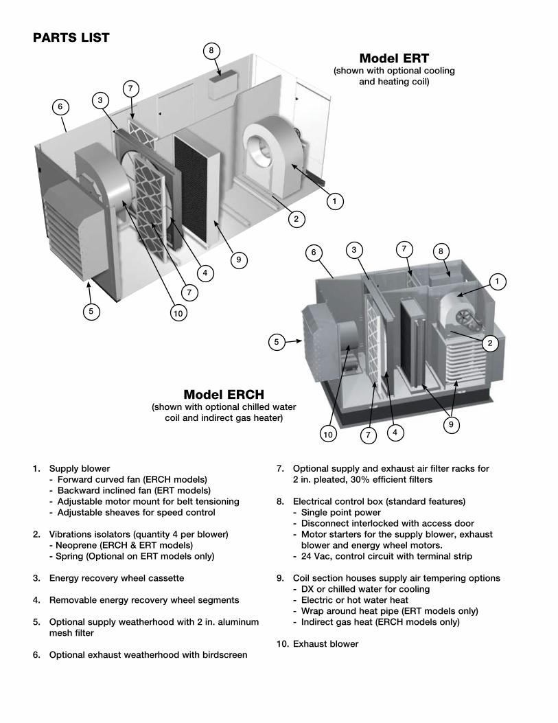
PARTS LIST
1
�
3
8
4
5
6
1
�
3
4
8
5
6
7
7
7
7
9
9
Model ERT(shown with optional cooling
and heating coil)
Model ERCH(shown with optional chilled water
coil and indirect gas heater)
10
10
1 . Supply blower - Forward curved fan (ERCH models) - Backward inclined fan (ERT models) - Adjustable motor mount for belt tensioning - Adjustable sheaves for speed control
� . Vibrations isolators (quantity 4 per blower) - Neoprene (ERCH & ERT models) - Spring (Optional on ERT models only)
3 . Energy recovery wheel cassette
4 . Removable energy recovery wheel segments
5 . Optional supply weatherhood with � in . aluminum mesh filter
6 . Optional exhaust weatherhood with birdscreen
7 . Optional supply and exhaust air filter racks for � in . pleated, 30% efficient filters
8 . Electrical control box (standard features) - Single point power - Disconnect interlocked with access door - Motor starters for the supply blower, exhaust
blower and energy wheel motors . - �4 Vac, control circuit with terminal strip
9 . Coil section houses supply air tempering options - DX or chilled water for cooling - Electric or hot water heat - Wrap around heat pipe (ERT models only) - Indirect gas heat (ERCH models only)
10 . Exhaust blower

Basic Unit The ERCH and ERT units are pre-wired such that when a call for outside air is made (via field supplied �4 VAC control signal wired to unit control center), the supply fan, exhaust fan and energy wheel are energized and optional motorized dampers open . The ERCH and ERT units can be supplied with or without heating and cooling coils . For units with coils, controls can be supplied by Greenheck or by the controls contractor . If supplied by the controls contractor, they would provide, mount, and wire any temperature controllers and temperature or relative humidity sensors required for the unit to discharge air at the desired conditions . However, temperature, pressure, and current sensors can be provided by Greenheck for purposes of monitoring via the Building Management System (see Optional Accessories section) .
Summer Operation:
Outdoor air is preconditioned (temperature and moisture levels are decreased) by the transfer of energy from the cooler, drier exhaust air via the energy recovery wheel . Units supplied with cooling coils can further cool the air coming off the wheel and strip out moisture to levels at or below room design . A heating coil downstream of the cooling coil can reheat the air to a more comfortable discharge temperature to the space .
The ERT model can be supplied with a wrap around heatpipe for additional precooling of the outdoor air prior to entering the cooling coil . The heatpipe also provides reheat after the cooling coil for applications where the outdoor needs to be provided at a space neutral condition .
Economizer Operation: See Economizer Application/Operation section .
Winter Operation:
Outdoor air is preconditioned (temperature and moisture levels are increased) by the transfer of energy from the warmer, more humid exhaust air via the energy recovery wheel . Units supplied with heating coils can further heat the air coming off the wheel to levels at or above room design .
Frost Control Operation: See Frost Control Application/Operation section .
Other Accessories:
Rotation Sensor See Optional Accessories section
Dirty Filter Sensor See Optional Accessories section
CO� Sensor See Optional Accessories section
VFD on Blowers VFDs on blowers are often used as part of a demand control ventilation system . This type of system takes advantage of varying occupancy through the use of CO� sensors to monitor space CO� levels . If CO� levels are low in the space, the VFD will operate the blowers at minimum airflow required by code . As the space occupancy increases and CO� levels increase, the VFD will increase the amount of fresh outdoor air being brought in to offset the CO� levels in the space (exhaust airflow is increased proportionally as outdoor airflow increases) . As CO� levels come back down, the airflow will decrease back to minimum requirements .
Night Setback On a call for night setback (unoccupied mode), the outdoor air damper will close and the energy wheel and exhaust fan will be de-energized . The night setback dampers will open and the supply fan will remain on, providing 100% recirculation . Units supplied with heating and cooling coils will temper air as required by the controls to maintain desired conditions in the space .
SEQUENCE OF OPERATION

40
Test and Balance ReportThe test and balance report (TAB) is utilized to determine whether the appropriate amount of outdoor air and exhaust air is being supplied and removed from a building, respectively . There are no set rules on what information must be included in a TAB report . As such, if a TAB report indicates that the airflow on a unit is low, prior to contacting the factory, please determine the following information:
Airflow problems can often be tied back to improper ductwork installation . Be sure to install ductwork in accordance with SMACNA and AMCA guidelines .
Unit #1 Unit #2 Unit #3 Unit #4
Model Number
Serial Number
Name Plate Information
Voltage
Hertz
Phase
Outdoor Air Fan Amps
Exhaust Fan Amps
Outdoor Air Fan Horsepower
Exhaust Fan Horsepower
Design Airflow
Outdoor Air
Exhaust
Measured Airflow
Outdoor Air
Exhaust
Measured Data
Blower Rotation
Outdoor Air Fan RPM
Exhaust Fan RPM
Outdoor Air Fan Amp Draw
Exhaust Fan Amp Draw
Pressure Drop Across Energy Recovery Wheel
Outdoor Air Side
Exhaust Side
Troubleshooting Airflow

41
*Alwaysprovidetheunitmodelandserialnumberwhenrequestingpartsorserviceinformation.*Alwayscheckmotorampsandcomparetonameplaterating.
Control power (�4 Vac) wiring run is too long (resistance should not exceed 0 .75 ohms) .
Shorten wiring run to mechanical room or install a relay which will turn unit on/off (Consult factory for relay information) .
Incoming supply power is less than anticipated . Voltage supplied to starter coil must be within +10% / -15% of nominal voltage stated on the coil .
Need to increase supply power or use a special control transformer which is sized for the actual supply power .
Motor Starters “Chatter” or
Do Not Pull In
Blown fuse or open circuit breaker .
Replace fuse or reset circuit breaker and check amps .
Possible CauseSymptom Corrective Action
Defective motor or capacitor . Replace .
Motor starter overloaded . Reset starter and check amps .
Electrical . Check for On/Off switches . Check for correct supply voltage .
Drive . Check for broken or loose belts . Tighten loose pulleys .
Blower Fails to Operate
Cfm too high . Check cfm and adjust drives if needed .
Static pressures are higher or lower than design .
If higher, ductwork should be improved .If lower, fan rpm should be lower .
Blower rotation is incorrect . Check rotation and reverse if necessary .
Motor voltage incorrect . Check motor nameplate versus supplied voltage .
Motor horsepower too low . See specifications and catalog for fan curves to determine if horsepower is sufficient .
Motor Over Amps
Shorted windings in motor . Replace motor .
Unit damper not fully open . Adjust damper linkage or replace damper motor .
System static pressure too high Improve ductwork to eliminate losses using good duct practices .
Blower speed too low . Check for correct drives and rpm with catalog data .
Fan wheels are operating backwards .
For 3-phase, see Direction of Fan Wheel Rotation under Unit Start-Up section .
Dirty filter or energy wheel . Follow cleaning procedures in Routine Maintenance section .
Leaks in ductwork . Repair .
Elbows or other obstructions may be obstructing fan outlet .
Correct or improve ductwork .
Belt slippage . Adjust belt tension .
Blower fan speed too high . Check for correct fan rpm . Decrease fan speed if necessary .
Filter(s) not in place . Install filters .
Insufficient static pressure (Ps) (airflow resistance) .
Induce Ps into system ductwork . Make sure grilles and access doors are installed . Decrease fan speed if necessary .
Low Airflow (cfm)
High Airflow (cfm)
Troubleshooting

4�
*Alwaysprovidetheunitmodelandserialnumberwhenrequestingpartsorserviceinformation.*Alwayscheckmotorampsandcomparetonameplaterating.
Energy Wheel Does NOT Turn
Blower fan motor overloads are tripping and auto-resetting .
Decrease fan speed .
Possible CauseSymptom Corrective Action
Exhaust Only frost control sensors are tripping .
Adjust frost temperature sensor set point as needed .
Air seals are too tight . See Energy Recovery Wheel under Unit Start-Up section .
“Economizer” sensors are operating .
Adjust temperature or enthalpy set points as needed .
No power to wheel motor . Make sure wheel drive is plugged in . Verify power is available .
Wheel drive belt Check for loose or broken belts . Replace belts . Consult factory .
One or Both Blowers Turn Off Intermittently and
Back on After About � Minutes
Wheel motor overloads are tripping, due to rubbing between wheel and air seals .
Recheck air seals, make sure they are not too tight . See Energy Recovery Wheel under Unit Start-Up Section .
Fan wheel rubbing on inlet Adjust wheel and/or inlet cone . Tighten wheel hub or bearing collars on shaft .
Bearings . Replace defective bearings (s) . Lubricate bearings . Tighten collars and fasteners .
Wheel out of balance . Replace or rebalance .
Loose wheel on shaft . Tighten wheel setscrew .
Energy Wheel Runs Intermittently
Loose motor or blower sheave . Tighten sheave setscrew .
Belts too loose . Adjust belt tension after �4 hours of operation .
Belts too tight . Loosen to maintain a 3/8 inch deflection per foot of span between sheaves .
Worn belt . Replace .
Motor base or blower loose . Tighten mounting bolts .
Build-up of material on wheel . Clean wheel and housing .
Bearing and drive misaligned . Realign .
Noise being transmitted by duct .
Make sure ductwork is supported properly . Make sure ductwork metal thickness is sized for proper stiffness . Check duct size at discharge to ensure that air velocities are not too high .
Excessive Noise or Vibration
Troubleshooting

43
Notes:

#460945 IOM ERT/ERCHRev . 3, February �008
Copyright © �008 Greenheck Fan Corp .
WarrantyGreenheck warrants this equipment to be free from defects in material and workmanship for a period of one year from the purchase date . The energy recovery wheel is warranted to be free from defects in material and workmanship for a period of five years from the purchase date . Any units or parts which prove defective during the warranty period will be replaced at our option when returned to our factory, transportation prepaid .
Motors are warranted by the motor manufacturer for a period of one year . Should motors furnished by Greenheck prove defective during this period, they should be returned to the nearest authorized motor service station . Greenheck will not be responsible for any removal or installation costs .
As a result of our commitment to continuous improvement, Greenheck reserves the right to change specifications without notice .