installation, operation and maintenance manualwebmedia.greenheck.com/iomuser/iom/464652 vektor-mh md...
TRANSCRIPT

General Safety InformationOnly qualified personnel should install this fan system. Personnel should have a clear understanding of these instructions and should be aware of general safety precautions. Improper installation can result in electric shock, possible injury due to coming in contact with moving parts, as well as other potential hazards. Other considerations may be required if high winds or seismic activity are present. If more information is needed, contact a licensed professional engineer before moving forward.
1. Follow all local electrical and safety codes, as well as the National Electrical Code (NEC), the National Fire Protection Agency (NFPA), where applicable. Follow the Canadian Electrical Code (CEC) in Canada.
2. The rotation of the wheel is critical. It must be free to rotate without striking or rubbing any stationary objects.
3. Motor must be securely and adequately grounded.4. Do not spin fan wheel faster than maximum
cataloged fan rpm. Adjustments to fan speed significantly effects motor load. If the fan RPM is changed, the motor current should be checked to make sure it is not exceeding the motor nameplate amps.
5. Do not allow the power cable to kink or come in contact with oil, grease, hot surfaces or chemicals. Replace cord immediately if damaged.
6. Verify that the power source is compatible with the equipment.
7. Never open access doors to a duct while the fan is running.
DANGERAlways disconnect power before working on or near a fan. Lock and tag the disconnect switch or breaker to prevent accidental power up.
CAUTIONWhen servicing the fan, motor may be hot enough to cause pain or injury. Allow motor to cool before servicing.
CAUTIONPrecaution should be taken in explosive atmospheres.
Vektor-MH, Vektor-MD, and Vektor-MS
Table of ContentsGeneral Safety Information . . . . . . . . . . . . . . . . . . . . . .1 Receiving / Unpacking / Handling / Storage . . . . . 2-3General Information Unit and System Identification . . . . . . . . . . . . . . . . . .3 Pre-Installation Information . . . . . . . . . . . . . . . . . . . .3 Electrical Disconnects / Moving Parts / Guards . . . .3 Air Pressure and Suction . . . . . . . . . . . . . . . . . . . . . .3System Components . . . . . . . . . . . . . . . . . . . . . . . . . 4-5Roof Curb and Mounting Details . . . . . . . . . . . . . . . . .5Bypass Air Plenum Rigging, Lifting and Installation . . . . . . . . . . . . . . . 6-7Fan Housing Rigging, Lifting and Installation . . . . . . . . . . . . . . . 6-7 Nozzle, Windband, Silencer, Weatherhood . . . . . . . .8Duct Connections - Side Inlet . . . . . . . . . . . . . . . . . . .9 Bottom Inlet . . . . . . . . . . . . . . . . .9Plenum Drainage Piping / Trap Detail . . . . . . . . . . . . . .9Bypass Air Plenum - Isolation Damper and Actuator Mounting . . . . . . . . . . . . . . . . . . . . . . . . . .10Field Coating Touch-Up . . . . . . . . . . . . . . . . . . . . . . .10Electrical Connections . . . . . . . . . . . . . . . . . . . . . . . .11Start-Up . . . . . . . . . . . . . . . . . . . . . . . . . . . . . . . . . . . .12Vibration . . . . . . . . . . . . . . . . . . . . . . . . . . . . . . . . . . .13Routine Maintenance Fan / V-Belt Drive / Motors / Bearings / Nozzle 14-15V-Belt Drive Installation . . . . . . . . . . . . . . . . . . . . . . . .15Bearing Replacement - Belt or Direct Drive . . . . . 16-17Jib Crane Assembly (Optional) . . . . . . . . . . . . . . . . . .17Motor Change-Out Procedure . . . . . . . . . . . . . . . . . .18High Strength Metal Disc Coupling. . . . . . . . . . . . . . .18Troubleshooting . . . . . . . . . . . . . . . . . . . . . . . . . . . . . .19Nozzle Parts and Assembly . . . . . . . . . . . . . BackcoverOur Commitment . . . . . . . . . . . . . . . . . . . . . . Backcover
Installation, Operation and Maintenance ManualPlease read and save these instructions for future reference. Read carefully before attempting to assemble, install, operate or maintain the product described. Protect yourself and others by observing all safety information. Failure to comply with instructions could result in personal injury and/or property damage!
1Laboratory Exhaust Systems
®
®
Document 464652 Model Vektor ®-MH, Vektor ®-MD
and Vektor®-MSLaboratory Exhaust System

Remove any accumulations of dirt, water, ice or snow and wipe dry before moving to indoor storage. To avoid “sweating” of metal parts allow cold parts to reach room temperature. To dry parts and packages use a portable electric heater to get rid of any moisture build up. Leave coverings loose to permit air circulation and to allow for periodic inspection.
The unit should be stored at least 3½ in. (89 mm) off the floor on wooden blocks covered with moisture proof paper or polyethylene sheathing. Aisles between parts and along all walls should be provided to permit air circulation and space for inspection.
OUTDOOR - Fans designed for outdoor applications may be stored outdoors, if absolutely necessary. Roads or aisles for portable cranes and hauling equipment are needed.The fan should be placed on a level surface to prevent water from leaking into the fan. The fan should be elevated on an adequate number of wooden blocks so that it is above water and snow levels and has enough blocking to prevent it from settling into soft ground. Locate parts far enough apart to permit air circulation, sunlight, and space for periodic inspection. To minimize water accumulation, place all fan parts on blocking supports so that rain water will run off.
Do not cover parts with plastic film or tarps as these cause condensation of moisture from the air passing through heating and cooling cycles.
Fan wheels should be blocked to prevent spinning caused by strong winds.
Inspection and Maintenance during StorageWhile in storage, inspect fans once per month. Keep a record of inspection and maintenance performed; see backcover.
If moisture or dirt accumulations are found on parts, the source should be located and eliminated. At each inspection, rotate the wheel by hand ten to fifteen revolutions to distribute lubricant on motor and bearings. Bearings should be lubricated at three month intervavls. The quantity of grease should be per the lubrication label.
If paint deterioration begins, consideration should be given to touch-up or repainting. Fans with special coatings may require special techniques for touch-up or repair.
Machined parts coated with rust preventive coating should be restored to good condition promptly if signs of rust occur. Immediately remove the original rust preventive coating with petroleum solvent and clean with lint-free cloths. Polish any remaining rust from surface with crocus cloth or fine emery paper and oil. Do not destroy the continuity of the surfaces. Wipe clean thoroughly with Tectyl® 506 (Ashland Inc.) or the equivalent. For hard to reach internal surfaces or for occasional use, consider using Tectyl® 511M Rust Preventive or WD-40® or the equivalent.
ReceivingGreenheck model Vektor-MH, Vektor-MD and Vektor-MS fans are thoroughly inspected, test run at the factory, and shipped on a skid or packaged to minimize damage during shipment. The transportation carrier has the responsibility of delivering all items in their original condition as received from Greenheck. The individual receiving the equipment is responsible for inspecting the unit for obvious or hidden damage and recording any damage on the bill of lading before acceptance of the equipment. All claims (if necessary) shall be filed with the final carrier.
UnpackingVerify that all required parts and the correct quantity of each item have been received, including accessory kit containing gasketing, etc. If any items are missing, report shortages to your local representative to arrange for obtaining missing parts. Sometimes it is not possible that all items for the unit be shipped together due to availability of transportation and truck space. Confirmation of shipment(s) must be limited to only items on the bill of lading.
HandlingThe Vektor-MH, Vektor-MD and Vektor-MS laboratory exhaust system is shipped in subassembly sections for easy rigging and installation. Depending on the fan size, the sections can include: Blower Assembly, Stack Extension, and Discharge Nozzle.
The Vektor-MH, Vektor-MD and Vektor-MS are designed to be self-supporting and standing (without the use of guy wires) when assembled per the instructions provided within this manual. If additional components are supplied, contact factory or reference submittal if additional supports or guy wires are required. All subassembly sections have lifting lugs as shown.
StorageFans are protected against damage during shipment. If the unit cannot be installed and operated immediately, precautions need to be taken to prevent deterioration of the unit during storage. The user assumes responsibility of the fan and accessories while in storage. The manufacturer will not be responsible for damage during storage. These suggestions are provided solely as a convenience to the user.
INDOOR - The ideal environment for the storage of fans and accessories is indoors, above grade, in a low humidity atmosphere which is sealed to prevent the entry of blowing dust, rain, or snow. Temperatures should be evenly maintained between 30° and 110°F. (-1°C and 43°C). Wide temperature swings may cause condensation and “sweating” of metal parts. All accessories must be stored indoors in a clean, dry atmosphere.
2 Laboratory Exhaust Systems®

General InformationTo ensure a successful installation, the instructions in this manual should be read and adhered to. Failure to comply with proper installation procedures may void the warranty.
Unit and System Identification TagsEach fan has a permanently affixed manufacturer’s engraved metal nameplate containing the model number and individual serial number.
The tag shown is an example of an identification nameplate on the fan. The information provides general details about the fan, as well as containing specific information unique to the unit. When contacting your Greenheck representative with future needs or questions, please have the information on this label available. Tags are mounted in an area which is clearly visible, usually on the side of the fan cabinet.
Vektor fan systems may arrive in component pieces due to shipping restrictions. Individual components of a system have matching identification tags which should be used to identify and assemble the complete system. Assembling systems with different identification tags can cause reductions in the fan(s) performance.
Prior to fully assembling and installing the Vektor-MH, Vektor-MD or Vektor-MS fans, inspect bypass air plenums and the fan assembly to make sure they are in working order.
Pre-Installation InformationBefore installation, it is important to be certain the mounting surface will bear the operating weight of the unit. For proper unit operation, it is also important that it be operated in a completely level position.
For further details on safety practices involving industrial and commercial fans, please refer to AMCA Publication 410.
REMOVING FROM STORAGEAs fans are removed from storage to be installed in their final location, they should be protected and maintained in a similar fashion, until the fan equipment goes into operation.
Prior to assembly and installation of the Vektor fan and system components, inspect the fan assembly to make sure it is in working order.
1. Check all fasteners, set screws on the fan, wheel, bearings, drive, motor base and accessories for tightness.
2. Rotate the fan wheel(s) by hand and assure no parts are rubbing. Access to the wheel is obtained through a bolted panel located on the side of the fan housing.
3. Ensure proper wheel settings for radial gap and alignment (see page 18).
Electrical DisconnectsAll fan motors should have disconnects located in close visual proximity to turn off electrical service. Service disconnects shall be locked-out when maintenance is being performed.
Moving PartsAll moving parts must have guards to protect personnel. Refer to local codes for requirements as to the number, type and design. Fully secure fan wheel before performing any maintenance. The fan wheel may start “free wheeling” even if all electrical power has been disconnected. Before the initial start-up or any restart, check the following items to make sure that they are installed and secure.
• Do not spin fan wheel faster than the maximum cataloged fan rpm.
• Adjustments to fan speed significantly affects motor load. If the fan RPM is changed, the motor current should be checked to make sure it is not exceeding the motor nameplate amps.
Guards (Motor Cover, Weatherhoods, Actuator Cover)Do not operate fans without proper protective devices in place. Failure to do so may result in serious bodily injury and property damage. Check local codes to ensure compliance for all protective devices.
Plenum Access DoorsBefore opening access doors, ensure the fan wheel has stopped moving and that the wheel has been secured from being able to rotate. Do not operate fan without access door in its fully closed position.
Air Pressure and SuctionIn addition to the usual hazards associated with rotating machinery, fans also create a dangerous suction at the inlet. Special caution needs to be used when moving around a fan, whether it is in operation or not. Before start-up, make sure the inlet area is clear of personnel and loose objects.
3Laboratory Exhaust Systems®

System Components
NOTE
Actual component pieces may vary from these images. Refer to your project submittal drawing.
Vektor-MD Assembly View - Direct DriveBelt and direct drive units share similar system components and assembly configuration.
Blower Housing
Windband
Nozzle
Bypass Air Plenum
Roof Curb or Structural Support
Vektor-MH Assembly View - Belt DriveBelt and direct drive units share similar system components and assembly configuration.
Blower Housing
Nozzle
Bypass Air Plenum
Roof Curb or Structural Support
Drain
Motor
Flex Coupling
Shaft Bearing
Fan Shaft
EXHAUST SYSTEM
VEKTOR-mdLABORATORY
Date: 02/14/2013Job: CAPS DRAWINGRevision: 00
GFC SO: Project #: VXXXXMark:
Model:
· RECOMMENDED EXHAUST DUCT INLET VELOCITY OF 1500 FPM OR LESS· DISCONNECTS MOUNTED & WIRED, MAY NEED TO BE RELOCATED DUE TO CODE· AS A RESULT OF OUR COMMITMENT TO CONTINUOUS IMPROVEMENT, GREENHECK
RESERVES THE RIGHT TO CHANGE SPECIFICATIONS WITHOUT NOTICE.
DWG #: S9464Drawn BY: BJH
Direct Drive
Bypass Damper Actuator Access Door
Weatherhood with Birdscreen
Isolation Damper
Blower Housing Access Door
Access PanelBolted / Gasketed
(all sides)
Isolation DamperActuator Cover
Motor Cover/Access
Weatherhood with Birdscreen
Panel Lifting Lugs
Isolation Damper
Isolation DamperActuator Cover
Blower Housing Access Door
Access PanelBolted / Gasketed
(all sides)
Bypass Damper Actuator Access Door
Motor Cover Lifting Lug
Panel Lifting Lugs
4 Laboratory Exhaust Systems®

Roof Curb and Mounting Details
Refer to stand-alone Vektor Roof Curb Assembly Instruction found on greenheck.com within the Laboratory Exhaust section. Chose applicable product model.
The figures illustrates three common methods used to install Vektor systems. Methods used to attach a Vektor unit are dependent on local codes, roof construction design and roof construction materials. Consult an architect or structural engineer for proper means of attachment.
NOTESteel, concrete or wood roof support is per structural engineer and in accordance with load requirements and applicable building codes.
Wood
STEEL STRUCTURAL SUPPORT(BY OTHERS, SEE NOTE ABOVE)
Continuous weld or stitch weld.Minimum 6 inch (152.4 mm) stitch weld by 3.25 inch (82.5 mm) spacing minimum. Minimum 6 inch (152.4 mm) weld on each corner.ORInstall 5/16 inch (7.9375 mm) 24 Dril-Flex® Self-DrillingTapping Screws. 3/16 inch (4.7625 mm) minimum thread engagement into A36 steel, centered in flange.4.5 inch (114.3 mm) spacing5/8 inch (15.875 mm) minimum edge distanceALL HARDWARE BY OTHERS
A A
NOTE:STEEL, CONCRETE OR WOOD ROOF SUPPORT IS PERSTRUCTURAL ENGINEER AND IN ACCORDANCE WITH LOAD REQUIREMENTS AND APPLICABLE BUILDING CODES.
VEKTOR ROOF CURB INSTALLATION GUIDE
Downloaded Dril-Flex information and used this drawing from their PDF document.7/30/2012
CONCRETE STRUCTURAL SUPPORT(BY OTHERS, SEE NOTE ABOVE)
Install 3/8 inch (9.525 mm) SS power wedge bolts2.5 inch (63.5 mm) maximum spacing from curb corners4.5 inch (114.3 mm) maximum bolt spacing3.5 inch (88.9 mm) minimum embedment4.5 inch (114.3 mm) minimum edgedistance centered in flangeALL HARDWARE BY OTHERS
WOODEN STRUCTURAL SUPPORT(BY OTHERS, SEE NOTE ABOVE)
Greenheck Roof Curb Greenheck Roof CurbGreenheck Roof Curb
Install 3/8 inch (9.525 mm) SS lag or thru-bolt with 1 inch (25.4 mm) O.D. washer2.5 inch (63.5 mm) maximum spacing from curb corners4.5 inch (114.3 mm) maximum bolt spacing3.5 inch (88.9 mm) minimum tread engagement, not including tapered tip2 inch (50.8 mm) minimum edge distance, centered in flangePre-drill holes 40-60% of lag diameterALL HARDWARE BY OTHERS
STEEL CONCRETE WOOD
JWE
VEKTOR ROOF CURBINSTALLATION GUIDE
02/10/2010
Steel
Concrete
STEEL STRUCTURAL SUPPORT(BY OTHERS, SEE NOTE ABOVE)
Continuous weld or stitch weld.Minimum 6 inch (152.4 mm) stitch weld by 3.25 inch (82.5 mm) spacing minimum. Minimum 6 inch (152.4 mm) weld on each corner.ORInstall 5/16 inch (7.9375 mm) 24 Dril-Flex® Self-DrillingTapping Screws. 3/16 inch (4.7625 mm) minimum thread engagement into A36 steel, centered in flange.4.5 inch (114.3 mm) spacing5/8 inch (15.875 mm) minimum edge distanceALL HARDWARE BY OTHERS
A A
NOTE:STEEL, CONCRETE OR WOOD ROOF SUPPORT IS PERSTRUCTURAL ENGINEER AND IN ACCORDANCE WITH LOAD REQUIREMENTS AND APPLICABLE BUILDING CODES.
VEKTOR ROOF CURB INSTALLATION GUIDE
Downloaded Dril-Flex information and used this drawing from their PDF document.7/30/2012
CONCRETE STRUCTURAL SUPPORT(BY OTHERS, SEE NOTE ABOVE)
Install 3/8 inch (9.525 mm) SS power wedge bolts2.5 inch (63.5 mm) maximum spacing from curb corners4.5 inch (114.3 mm) maximum bolt spacing3.5 inch (88.9 mm) minimum embedment4.5 inch (114.3 mm) minimum edgedistance centered in flangeALL HARDWARE BY OTHERS
WOODEN STRUCTURAL SUPPORT(BY OTHERS, SEE NOTE ABOVE)
Greenheck Roof Curb Greenheck Roof CurbGreenheck Roof Curb
Install 3/8 inch (9.525 mm) SS lag or thru-bolt with 1 inch (25.4 mm) O.D. washer2.5 inch (63.5 mm) maximum spacing from curb corners4.5 inch (114.3 mm) maximum bolt spacing3.5 inch (88.9 mm) minimum tread engagement, not including tapered tip2 inch (50.8 mm) minimum edge distance, centered in flangePre-drill holes 40-60% of lag diameterALL HARDWARE BY OTHERS
STEEL CONCRETE WOOD
JWE
VEKTOR ROOF CURBINSTALLATION GUIDE
02/10/2010
Vektor-MS Assembly View - Direct DriveBelt and direct drive units share similar system components and assembly configuration.
Bypass Damper Actuator Access Door
Weatherhood with Birdscreen
Isolation Damper
Blower Housing Access Door
Access PanelBolted / Gasketed
(all sides)
Isolation DamperActuator Cover
Panel Lifting Lugs
Blower Housing
SAVVE Nozzle
Bypass Air Plenum
Roof Curb or Structural Support
5Laboratory Exhaust Systems®

Bypass Air Plenum - Rigging, Lifting and InstallationPrior to lifting any components, verify the weights on the project submittal drawings for each component or contact factory. Do not lift weights beyond the capacities of the on-site lifting equipment. Proper handling of the equipment is critical to avoid damage to the unit.
Prior to setting the bypass air plenum (BAP), secure 1/4-inch thick by 3/4-inch wide EPDM gasket (provided) around the perimeter of the roof curb top edge, if mounting on a roof curb.
Bypass Air Plenum - Rigging and LiftingEach section will have four (4) lifting points. All lifting points must be used when lifting. Spreader bars of sufficient length need to be used to prevent damage to BAP walls and components mounted to the BAP.
1. Always use all lifting lugs provided by manufacturer. Lifting lugs are located around the perimeter of each section.
2. A spreader bar must be used when lifting each section to distribute the weight evenly and to prevent the unit from being over-torqued. Avoid unnecessary jarring or rough handling.
3. Care must be taken to keep the unit in the upright position during rigging.
4. Care must be taken to not damage the watertight seams in the unit casing.
5. Avoid damage to the curb and curb gasketing when rigging onto a curb.
6. Only use trained professional riggers when moving equipment.
Bypass Air Plenum InstallationBypass air plenums (BAP) are delivered fully assembled unless shipping restrictions require multiple sections. If delivered in sections, all materials required to join plenum sections together are provided.
Bypass air plenums are modular in construction and can be disassembled to provide allowances for lower on-site lifting capacities. Plenum sections are joined using stainless steel fasteners. These are removed to separate sections for lifting purposes. Save hardware as these will be required to join the BAP sections together again.
If moving separate sections onto a roof curb or support structure, each section should be joined to its mating section after moving into position and before lifting any additional section(s) into position.
Steps for joining multiple BAP sections together:
1. Lift / place first BAP section making sure that mounting holes are positioned with curb mounting holes or to structure BAP will be secured.
2. Attached provided gasket to plenum section using the pattern shown in the image.
3. Ensure bolts are removed from both mating sections to being joined together. Plenum will ship with hardware in one section’s bolt holes or were removed to disassemble BAP to reduce lifting load.
4. Lift / place next section into position using similar lifting procedure.
5. Align holes between two mating sections. 6. Use fasteners (provided) to join the two sections
together, this will involve utilizing the nutserts in each section on the inside perimeter. The fasteners are tightened until the sections are pulled together and the gasket material is compressed.
7. Caulk joint (provided) on the top and two sides between sections for enhanced water protection.
8. Repeat steps 1 – 7 until all plenum sections are lifted and joined together.
Any side panels removed to gain access to the interior of the plenum should be reattached.
Gasket Materialeach plenum section
Bolt Holes
Plenum Section
Each plenum section has four (4) lifting points.Each plenum section has four (4) lifting points.
Plenum is lifted by using all lifting points on Plenum is lifted by using all lifting points on all plenum sections.all plenum sections.
Spreader Bar
Chains
Lifting PointsLifting Points
Each plenum section has four (4) lifting points.Each plenum section has four (4) lifting points.
Plenum is lifted by using all lifting points on Plenum is lifted by using all lifting points on all plenum sections.all plenum sections.
Spreader Bar
Chains
Lifting PointsLifting Points
Two fan bypass air plenum shown. Plenums may be single sections or up to six in length
6 Laboratory Exhaust Systems®

Motor CoverLifting Lug
Lifting Lugs
Lifting Brackets
Fan Housing InstallationLower Vektor fan housing into place. Allow gasket to become compressed before securing to plenum.
Install moly-coated 316 stainless steel screws (provided) in all holes in plenum cap.
Securing the Bypass Air PlenumAfter bypass air plenum (BAP) has been lifted into position, plenum should be secured to roof curb, structural steel or concrete pad. Bottom of the BAP has a removable skirt section with pre-punched holes. These holes will align with holes and nutserts in the roof curb if the roof curb was provided by Greenheck. If the roof curb is from another supplier use the holes in the skirt as a template.
Allow gasketing to compress before securing. When securing BAP to curb install using moly-coated 316 stainless steel screws (provided) in all holes.
If BAP is not being mounted on a roof curb, it can be secured to either structural steel or concrete pad. Full perimeter and cross support under the BAP is required. Method used to secure the BAP to either structural support(s) or concrete pad is determined by site or structural engineer. If BAP is welded to support structure repair the area where coating was burnt off. See coatings repair section of this manual for details involving touch-up of damaged surfaces.
Fans – Rigging, Lifting and Installation
Prior to setting fan(s) on plenum, place 1/4-inch thick x 3/4-inch wide EPDM gasket around the perimeter of top edge of BAP where fans mount, adhesive side down (gasket provided).
Fans - Rigging and LiftingFans are to be rigged and moved by the lifting brackets provided or by the skid when a forklift is used. Location of brackets varies by model and size. Handle in such a manner as to keep from scratching or chipping the coating. Damaged finish may reduce ability of fan to resist corrosion. See coating repair section of this manual for details involving touch-up of damaged surfaces.
Vektor-MD fans size 40 and larger and all MH and MS fans are shipped with the nozzle separate from the main housing. For these sizes the nozzle should be lifted separate from the fan. For MD models with the nozzle attached the main fan housing can be lifted using the brackets on the nozzle.
• Use standard lifting and rigging practices.• ALL lifting lugs (brackets) on each component must
be utilized at the same time.• Fan to be kept level during lifting and installation.
CAUTIONFans should never be lifted by the shaft, motor, motor cover or accessories.
Vektor MD - sizes 40 and greaterVektor MH and MS - all sizes
Vektor MD - sizes 36 and smaller
7Laboratory Exhaust Systems®

Nozzle and Windband Lifting and Installation for Vektor-MD
Vektor MD - sizes 36 and smaller, nozzle is attached to the fan housing
Using the windband lifting lugs, lift and place over the nozzle attached to the fan housing discharge. The windband has support brackets welded around the interior perimeter. Align the windband support bracket bolt holes with the bolt holes in the nozzle. Using the provided moly-coated 316 stainless steel bolts and nuts, securely attach these pieces together.
Vektor MD - sizes 40 and greater, windband and nozzle ship as individual pieces
Using the nozzle lifting brackets, lift and place over the fan discharge. Secure nozzle using moly-coated stainless steel hardware (provided). Align support bracket holes with bolt holes in the nozzle. Attach windband using the provided moly-coated 316 stainless steel bolts through the support brackets welded to the inside of the windband.
LiftingLug
LiftingLug
WindbandWindband
Support Brackets
• Vektor MD-36 and smaller, attached to fan • Vektor MD-40 and greater, shipped loose
NozzleNozzle
Windband
NozzleNozzle
LiftingLug
LiftingLug
WindbandWindband
Support Brackets
• Vektor MD-36 and smaller, attached to fan • Vektor MD-40 and greater, shipped loose
NozzleNozzle
Windband
NozzleNozzleWeatherhood InstallationShipping constraints may require weatherhoods to be delivered separate from the BAP. The weatherhood bolt hole pattern matches the side panel bolt pattern. Use supplied hardware to secure the weatherhood to the BAP over the bypass air damper.
Nozzle Lifting and Installation for Vektor-MHUsing the nozzle lifting lugs, place nozzle over blower discharge, aligning support bracket holes with bolt holes in blower housing. Attach nozzle to blower discharge using moly-coated 316 stainless steel bolts and nuts provided through the flange.
LiftingLug
LiftingLug
Silencer and Stack Extension Lifting and Installation for Vektor-MH / Vektor-MD
Systems supplied with inline discharge silencers always have the nozzle section ship separate. The silencer is installed between the fan housing and nozzle.
Lift the silencer with provided lifting points. When systems are supplied with silencers, guy wires or independent supports are recommended (by others). Refer to project specific submittal drawings for details.
Lifting Points
Nozzle Lifting and Installation for Vektor-MSUsing the nozzle lifting lugs, place nozzle over blower discharge, aligning support bracket holes with bolt holes in blower housing. Attach nozzle to blower discharge using moly-coated 316 stainless steel bolts and nuts provided through the flange.
Lifting Lugs
8 Laboratory Exhaust Systems®

Duct Connections to the Bypass Air Plenum (BAP)Connecting primary inlet exhaust air ducts is allowed through the roof curb or through one or more of the side access panels. To reduce the potential for system effects in the plenum, the duct connection should be sized to have no more than a maximum air velocity of 1500 fpm when entering. When attaching ductwork to the plenum, care should be taken to ensure a tight fit and proper seal to prevent leakage from the contaminated airstream.
Side Inlet Duct ConnectionsDuctwork that has a different size than the removable access panel(s) can either have a transition to the plenum’s opening size or the access panel can be field modified by cutting an opening to the size of the ductwork.
Bottom Inlet Duct ConnectionsBottom inlet duct connects should be made by attaching the duct to the inside panel edge of the plenum. Ducting to multiple fan plenums may either be split below the roof level and connected to duct drops from the inside the plenum or having the ducting notched for fitting around roof curb and plenum cross support members.
Plenum Drainage Piping / Trap Detail (By Others)
There is a location for a pipe connection on each tubular fan housing and bypass air plenum. Each drain may need to be connected to a drainage system to ensure proper disposal of any water or condensate that may occur.
• Drain connections are 0.5 inch FNPT and 1.0 inch MNPT
• Installed piping to have a downward angle to allow for drainage
• Fill traps to recommended level before start-upNote: A conservative method of trap design is to set N
= total static pressure.
Check local codes for proper disposal of drain water which has been in contact with the exhaust air.
Positive Pressure Trap on Tubular Fan Housing
Fan Drain Connection
Plenum Drain Connection
Negative Pressure Trap on Bypass Air Plenum
RECOMMENDED DRAIN TRAP DESIGN(TRAP BY OTHERS)
FAN BYPASSAIR PLENUM
ENERGY RECOVERYPLENUM
SUBFLOOR SUBFLOOR
1.25 NPT.75 NPT *BASED ON STANDARD VEKTOR ERS CURB HEIGHTS
**
ROOFCURB
ROOFCURB
P.O.BOX 410 SCHOFIELD, WISCONSIN 54476-0410
TITLE
DRAWN BY ECO
B
ENG. REF.DATE
SUPERSEDES
SCALE
CAD DRAWING NO.
FAUST
06/29/2009
1/8
VK-ERS
N = Negative fan pressure (inches W.C.)H = N - 0.5 inches minimum
Note: A conservation method of trap design is to set N = TSP and P = TSP (TSP = Total Static Pressure)
H/2 H/2H
1.25 inch minimum
N
FAN ONFAN OFF
NEGATIVE PRESSURE TRAP
14.75014.000NOTE: INSULATION OR OTHER MEANS OF FREEZE PROTECTION MAY BE REQUIRED IN CERTAIN CLIMATES
RECOMMENDED DRAIN TRAP DESIGN(TRAP BY OTHERS)
N = Negative fan pressure (inches W.C.)H = N - 0.5 inches minimum)
NOTE: A conservative method of trap design is to setN = Total Static Pressure and P = Total Static Pressure
H/2 H/2H
1.25 inch minimum
N
FAN ONFAN OFF
POSITIVE PRESSURE TRAP
Connect this end to fan drain.
ERS DRAIN SUBMITTAL
RECOMMENDED DRAIN TRAP DESIGN(TRAP BY OTHERS)
FAN BYPASSAIR PLENUM
ENERGY RECOVERYPLENUM
SUBFLOOR SUBFLOOR
1.25 NPT.75 NPT *BASED ON STANDARD VEKTOR ERS CURB HEIGHTS
**
ROOFCURB
ROOFCURB
P.O.BOX 410 SCHOFIELD, WISCONSIN 54476-0410
TITLE
DRAWN BY ECO
B
ENG. REF.DATE
SUPERSEDES
SCALE
CAD DRAWING NO.
FAUST
06/29/2009
1/8
VK-ERS
N = Negative fan pressure (inches W.C.)H = N - 0.5 inches minimum
Note: A conservation method of trap design is to set N = TSP and P = TSP (TSP = Total Static Pressure)
H/2 H/2H
1.25 inch minimum
N
FAN ONFAN OFF
NEGATIVE PRESSURE TRAP
14.75014.000NOTE: INSULATION OR OTHER MEANS OF FREEZE PROTECTION MAY BE REQUIRED IN CERTAIN CLIMATES
RECOMMENDED DRAIN TRAP DESIGN(TRAP BY OTHERS)
N = Negative fan pressure (inches W.C.)H = N - 0.5 inches minimum)
NOTE: A conservative method of trap design is to setN = Total Static Pressure and P = Total Static Pressure
H/2 H/2H
1.25 inch minimum
N
FAN ONFAN OFF
POSITIVE PRESSURE TRAP
Connect this end to fan drain.
ERS DRAIN SUBMITTAL
Duct connections are to be sealed from air leakage and water penetration.
Flanged Bottom Inlet
Gasket/Seal(by others)
Bolt-On Mounting Skirt
Plenum bottom section view for single fan system.Repeated for multiple fan plenums.
Roof Curb or Structure
Duct Drop (by others)
Plenum bottom section view for single fan system.Repeated for multiple fan plenums.
9Laboratory Exhaust Systems®

Field Coating Touch-Up Procedure for Scratched AreasStandard coating and color for the Vektor laboratory exhaust system is Greenheck’s LabCoat™. The dark gray (041) procedure below details the correct method for repairing minor scratches in the coating.
1. Scuff affected area to be repaired using medium sandpaper (provided) or medium scotch brite pad. Feather the edges.
2. Clean affected area to be touched up using an alkaline based cleaner and rinse.
3. Apply Kem Kromik primer using 1 inch foam brush (provided). Follow technical data sheet instructions.
4. Allow primer to dry a minimum of 2 1/2 hours before top coating.
5. Apply topcoat with industrial enamel using 1 inch foam brush (provided). Follow technical data sheets instructions. Allow painted units to air-dry and cure before putting into service. See enclosed Technical Data sheets for detailed drying and cure schedules at different temperatures.
To order additional coating repair kits please reference Greenheck’s part number HAZ2203 HI-PRO 041 GRAY FIELD DAMAGE REPAIR kit. Please contact factory with your fan’s serial number for colors other than our standard Dark Gray (041).
Bypass Air Plenum (BAP) and Isolation Damper Access and Actuator MountingDepending on the configuration and intended operation of the system supplied, every Vektor plenum section may not have a weatherhood and bypass air damper. Typically systems that include a fan which is on standby will have one less weatherhood and BAP damper assembly than plenum sections. Refer to submittal drawings for additional information. The appropriate guard / cover needs to be removed for installation, inspection and maintenance.
For Vektor fans with weatherhood - Access to the BAP damper and the isolation damper, actuator(s) (optional from factory) and voltage transformer (optional from factory) mounting location, is gained through the removal of the weatherhood guard / cover. The isolation damper assembly can be removed from its location by sliding it through the opening.
For Vektor fans without a weatherhood - A guard / cover is located on the side of the plenum section. Removal of the guard / cover gains access to the damper linkages, actuator (optional from factory) and transformer (optional from factory). The entire isolation damper assembly can be removed through this opening.
If the Vektor units were not supplied with optional actuators, the dampers have an extended jackshaft for field mounting a customer supplied actuator.
TOUCH-UP PAINT REPAIR KIT CONTENTS • One pint of Kem Kromik primer
- including a technical data sheet • One pint of industrial enamel (041 Dark Gray)
- including a technical data sheet • Four disposable foam brushes • One sheet sandpaper • Repair procedure details
10 Laboratory Exhaust Systems®

Before electrical connections are made, the supply voltage, phase and ampere capacity must be checked for compatibility with the fan motor. In addition, the supply wiring must be properly fused and conform to local and national electrical codes. If the unit is supplied with a safety disconnect switch, ensure proper wiring to the fan motor. Be sure the disconnect is switched to the “OFF” position before connecting supply wires. If no disconnect is supplied, ensure the supply wire is not live before connection. Supply wires are then connected to the optional safety disconnect switch (if supplied) or motor.
Vektor-MH and Vektor-MD Motor Disconnect and Isolation Damper Wiring DiagramDisconnect is mounted to fan housing. Transformers are mounted to bypass air plenum with damper actuator motors. For systems that ship unassembled because of physical size, this connection at disconnect from transformers must be field-installed. Wires with conduit and fittings are provided pre-connected to transformers.
Electrical ConnectionsSingle Phase Layout
LINE IN115/208/230/277 volt, single phase
MOTOR
DISCONNECT115/208/230/277 volt
Single phase
TRANSFORMER208/230/277 volt, single phase
Transformers must be wired independent from VFD control.
24/115 volt, single phaseisolation damper actuator motor
power open/spring close115/208/230/277 volt
Single phase
Disconnect is mounted to fan housing
Optional transformer and isolation damper, refer to CAPS file selection
LINE IN208/230/460/575 volt, three phase
MOTOR
DISCONNECT208/230/460/575 volt
Three phase
TRANSFORMER208/230/460/575 volt, single phase
Transformers must be wired independent from VFD control.
24/115 volt, single phaseisolation damper actuator motor
power open/spring close
208/230/460/575 volt60 cycle, three phase
Disconnect is mounted to fan housing
Optional transformer and isolation damper, refer to CAPS file selection
LINE IN208/230/460/575 volt, three phase
MOTOR
DISCONNECT208/230/460/575 volt
Three phase
VFDsupplied and wired
by others
TRANSFORMER (if required)208/230/460/575 volt, single phase
Transformers must be wired independent from VFD control.
24/115 volt, single phaseisolation damper actuator motor
power open/spring close
208/230/460/575 volt60 cycle, three phase
Disconnect is mounted to fan housing
Optional transformer and isolation damper, refer to CAPS file selection
SINGLEPHASE LAYOUT
THREEPHASE LAYOUT
THREEPHASEWITH VFD LAYOUT
Field WiringFactory Wiring
Field WiringFactory Wiring
Field WiringFactory Wiring
LINE IN208/230/460/575 volt, three phase
MOTOR
DISCONNECT208/230/460/575 volt
Three phase
Motor Starterwith Intergral
Damper Control
24/115 volt, single phaseisolation damper actuator motor
power open/spring close
208/230/460/575 volt60 cycle, three phase
Disconnect is mounted to fan housing
Optional isolation damper, refer to CAPS file selection
MOTORSTARTERWITHINTERGRALDAMPER CONTROL
Field WiringFactory Wiring
Three Phase Layout
LINE IN115/208/230/277 volt, single phase
MOTOR
DISCONNECT115/208/230/277 volt
Single phase
TRANSFORMER208/230/277 volt, single phase
Transformers must be wired independent from VFD control.
24/115 volt, single phaseisolation damper actuator motor
power open/spring close115/208/230/277 volt
Single phase
Disconnect is mounted to fan housing
Optional transformer and isolation damper, refer to CAPS file selection
LINE IN208/230/460/575 volt, three phase
MOTOR
DISCONNECT208/230/460/575 volt
Three phase
TRANSFORMER208/230/460/575 volt, single phase
Transformers must be wired independent from VFD control.
24/115 volt, single phaseisolation damper actuator motor
power open/spring close
208/230/460/575 volt60 cycle, three phase
Disconnect is mounted to fan housing
Optional transformer and isolation damper, refer to CAPS file selection
LINE IN208/230/460/575 volt, three phase
MOTOR
DISCONNECT208/230/460/575 volt
Three phase
VFDsupplied and wired
by others
TRANSFORMER (if required)208/230/460/575 volt, single phase
Transformers must be wired independent from VFD control.
24/115 volt, single phaseisolation damper actuator motor
power open/spring close
208/230/460/575 volt60 cycle, three phase
Disconnect is mounted to fan housing
Optional transformer and isolation damper, refer to CAPS file selection
SINGLEPHASE LAYOUT
THREEPHASE LAYOUT
THREEPHASEWITH VFD LAYOUT
Field WiringFactory Wiring
Field WiringFactory Wiring
Field WiringFactory Wiring
LINE IN208/230/460/575 volt, three phase
MOTOR
DISCONNECT208/230/460/575 volt
Three phase
Motor Starterwith Intergral
Damper Control
24/115 volt, single phaseisolation damper actuator motor
power open/spring close
208/230/460/575 volt60 cycle, three phase
Disconnect is mounted to fan housing
Optional isolation damper, refer to CAPS file selection
MOTORSTARTERWITHINTERGRALDAMPER CONTROL
Field WiringFactory Wiring
Three Phase with Variable Frequency Drives Layout
Three Phase Motor Starter with Integral Damper Control Layout
LINE IN115/208/230/277 volt, single phase
MOTOR
DISCONNECT115/208/230/277 volt
Single phase
TRANSFORMER208/230/277 volt, single phase
Transformers must be wired independent from VFD control.
24/115 volt, single phaseisolation damper actuator motor
power open/spring close115/208/230/277 volt
Single phase
Disconnect is mounted to fan housing
Optional transformer and isolation damper, refer to CAPS file selection
LINE IN208/230/460/575 volt, three phase
MOTOR
DISCONNECT208/230/460/575 volt
Three phase
TRANSFORMER208/230/460/575 volt, single phase
Transformers must be wired independent from VFD control.
24/115 volt, single phaseisolation damper actuator motor
power open/spring close
208/230/460/575 volt60 cycle, three phase
Disconnect is mounted to fan housing
Optional transformer and isolation damper, refer to CAPS file selection
LINE IN208/230/460/575 volt, three phase
MOTOR
DISCONNECT208/230/460/575 volt
Three phase
VFDsupplied and wired
by others
TRANSFORMER (if required)208/230/460/575 volt, single phase
Transformers must be wired independent from VFD control.
24/115 volt, single phaseisolation damper actuator motor
power open/spring close
208/230/460/575 volt60 cycle, three phase
Disconnect is mounted to fan housing
Optional transformer and isolation damper, refer to CAPS file selection
SINGLEPHASE LAYOUT
THREEPHASE LAYOUT
THREEPHASEWITH VFD LAYOUT
Field WiringFactory Wiring
Field WiringFactory Wiring
Field WiringFactory Wiring
LINE IN208/230/460/575 volt, three phase
MOTOR
DISCONNECT208/230/460/575 volt
Three phase
Motor Starterwith Intergral
Damper Control
24/115 volt, single phaseisolation damper actuator motor
power open/spring close
208/230/460/575 volt60 cycle, three phase
Disconnect is mounted to fan housing
Optional isolation damper, refer to CAPS file selection
MOTORSTARTERWITHINTERGRALDAMPER CONTROL
Field WiringFactory Wiring
Vektor-MH and Vektor-MD Applications with Variable Frequency Drives (VFD)For Vektor systems with single-point, three-phase wiring per blower, the isolation damper actuator will be powered via a step-down transformer, which is wired to the fan disconnect, as shown in the appropriate diagram.
If fan flow (motor speed) is to be controlled using a variable frequency drive with this wiring, the reduced voltage and frequency supplied to the fan will cause control problems with the isolation damper actuator.
When a project’s Vektor control sequence requires the use of a VFD, it is suggested that the control contractor supply the isolation damper actuator voltage — independent of the power supplied to the Vektor fan motor.
NOTEFor Vektor-MS fans refer to the Vektor SAVVE controls Installation, Operation and Maintenance Manual for electrical wiring and connection information.
11Laboratory Exhaust Systems®

Start-Up
Visual Inspection of EquipmentThe equipment type and arrangement should be verified as ordered at once when it arrives at the jobsite. When a discrepancy is found, the local Greenheck Fan Corporation Sales Representative must be notified immediately so that corrective action may be investigated, also verify electrical conformance to specifications. Unauthorized alterations and unauthorized backcharges will not be recognized by Greenheck Fan Corporation.
After the unit has been assembled, installed and all utilities have been hooked up, the unit is now ready for operation.
CheckBefore starting the unit, check the following:
1. Confirm that building supply voltage matches the voltage for which the unit is wired.
2. Check all piping and wiring penetrations made by contractors for water tightness. All penetrations must be made watertight to prevent water damage to the unit and building.
3. Rotate the fan wheel manually to be sure that it is free to operate. Remove any dirt or debris that may have accumulated during installation.
4. Check the fan bearing setscrews for tightness. 5. Check alignment of sheaves and V-Belts (See
maintenance section). 6. Inspect all fasteners to ensure that none have
loosened during shipment. 7. Check flex coupling for proper alignment and
connect between motor shaft and fan shaft (direct drive).
8. Check all guarding to ensure that it is securely attached and not interfering with rotating parts.
9. Check operation of isolation and bypass dampers (if supplied) for freedom of movement.
10. Check all electrical connections for proper attachment.
11. Check housing and ductwork, if accessible, for obstructions and foreign material that may damage the fan wheel.
12. Fill drainage piping trap.
WARNING
Disconnect and secure to the OFF position all electrical power to the fan prior to inspection or servicing. Failure to comply with this safety precaution could result in serious injury or death.
Additional steps for initial start-up1. Check for proper wheel rotation by
momentarily energizing the fan. Access to view the wheel can be gained through the blower housing access panel located on the side of the fan’s tubular housing.
One of the most frequently encountered problems are motors that are wired to rotate the wheel in the wrong direction. This is especially true with 3-phase installations where the motor will run in either direction, depending on how it has been wired. To reverse rotation of a 3-phase motor, interchange any two of the three electrical leads. Single phase motors can be reversed by changing internal connections as described on the motor label or wiring diagram.
2. Fans with multi-speed motors should be checked on low speed during initial start-up.
3. Check for unusual noise, vibration or overheating of bearings. Refer to the “Troubleshooting” section of this manual if a problem develops.
4. Grease may be forced out of the bearing seals during initial start-up. This is a normal self-purging feature for the type of bearing used on this product.
Blower Housing Access Panel
Direction of wheel rotation
Airflow
12 Laboratory Exhaust Systems®

VibrationOn start-up and during operation, the unit should operate smoothly with minimal vibration. It is possible that a higher degree of vibration may be experienced. Excessive vibration if left unchecked, can cause a multitude of problems, including structural and/or
component failure. The most common sources of vibration are listed.
Many of these conditions can be discovered by careful observation. Refer to the troubleshooting section of this manual
for corrective actions. If observation cannot locate the source of vibration, a qualified technician using vibration analysis equipment should be consulted. If the problem is wheel unbalance, in-place balancing can be done through the access panel located on the side of each fan’s tubular housing. Any correction weights added to the wheel should be welded to either the wheel back (single-plane balance) or to the wheel back and wheel cone (two-plane balance).
1. Wheel Unbalance2. Drive Pulley Misalignment3. Incorrect Belt Tension4. Bearing Misalignment5. Mechanical Looseness6. Faulty Belts7. Drive Component Unbalance8. Poor Inlet/Outlet Conditions9. Foundation Stiffness
13Laboratory Exhaust Systems®
Routine Maintenance and Operation
Once the unit has been put into operation, a routine maintenance schedule should be set up to accomplish the following:
1. Lubrication of bearings and motor.2. Bypass air dampers should be checked for freedom
of operation and wear.3. Wheel, housing, bolts and set screws on the entire
fan should be checked for tightness.4. Any dirt accumulation on the wheel or in the housing
should be removed to prevent unbalance and possible damage.
5. Inspect fan impeller and housing looking for fatigue, corrosion, or wear.
MotorsMotor maintenance is generally limited to cleaning and lubrication. Cleaning should be limited to exterior surfaces only. Removing dust and grease buildup on the motor housing assists proper motor cooling. Never wash-down motor with high pressure spray.
Greasing of motors is only intended when fittings are provided. Many fractional motors are permanently lubricated for life and require no further lubrication. Motors supplied with grease fittings should be greased in accordance with the manufacturer’s recommendations. When motor temperature does not exceed 104ºF (40ºC), the grease should be replaced after 2000 hours of running time.
Direct drive systems have extended grease lines to lubricate the motor without removal of any guarding.
Fan OperationAll fans should be run every thirty (30) days, or at least “bumped” every thirty days. It is preferred that each fan is run as this causes all electrical and mechanical components to get up to temperature, displacing any formed condensation, redistributes load on bearings, and redistributes grease in the bearings (motor and shaft bearings).
V-Belt DriveV-belt drives must be checked on a regular basis for wear, tension, alignment and dirt accumulation. Premature or frequent belt failures can be caused by improper belt tension (either too loose or too tight) or misaligned sheaves. Abnormally high belt tension or drive misalignment will cause excessive bearing loads and may result in failure of the fan and/or motor bearings. Conversely, loose belts will cause squealing on start-up, excessive belt flutter, slippage and overheated sheaves. Either excessively loose or tight belts may cause fan vibration.
When replacing V-belts on multiple groove drives all belts should be changed to provide uniform drive loading. Use a set of matched belts whenever possible. Do not pry belts on or off the sheave. Loosen belt tension until belts can be removed by simply lifting the belts off the sheaves. After replacing belts, ensure that slack in each belt is on the same side of the drive. Belt dressing should never be used.
CAUTION
When operating conditions of the fan are to be changed (speed, pressure, temperature, etc.), consult manufacturer to determine if the unit can operate safely at the new condition.
CAUTIONWhen performing any service to the fan, disconnect the electrical supply and secure fan impeller.
Do not install new belts on worn sheaves. If the sheaves have grooves worn in them, they must be replaced before new belts are installed.
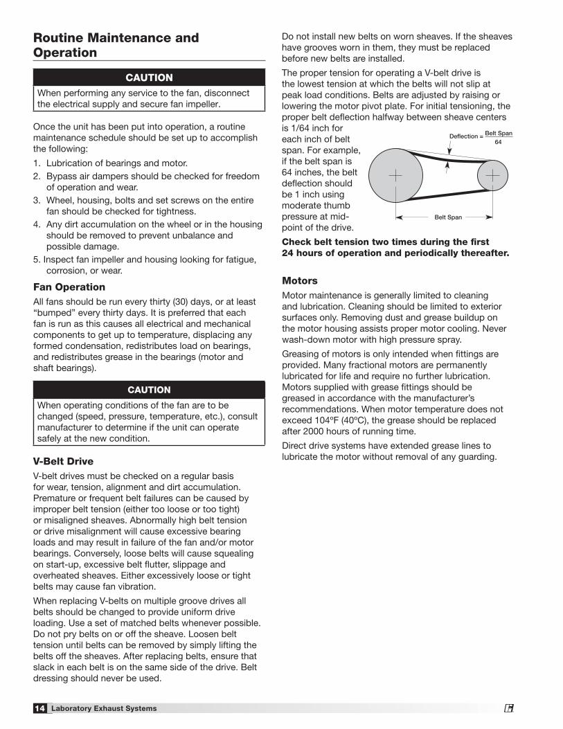
The proper tension for operating a V-belt drive is the lowest tension at which the belts will not slip at peak load conditions. Belts are adjusted by raising or lowering the motor pivot plate. For initial tensioning, the proper belt deflection halfway between sheave centers is 1/64 inch for each inch of belt span. For example, if the belt span is 64 inches, the belt deflection should be 1 inch using moderate thumb pressure at mid-point of the drive.
Check belt tension two times during the first 24 hours of operation and periodically thereafter.
Belt Span
Deflection = Belt Span64
14 Laboratory Exhaust Systems®
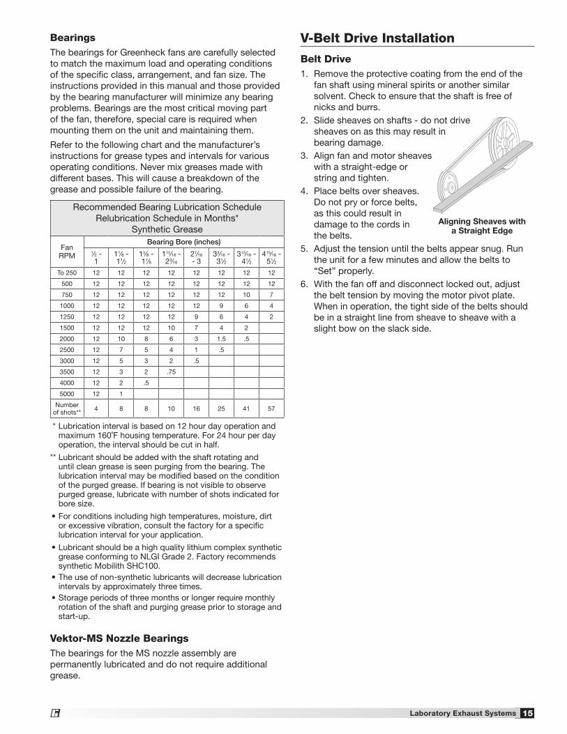
Recommended Bearing Lubrication ScheduleRelubrication Schedule in Months*
Synthetic Grease
Fan RPM
Bearing Bore (inches)1⁄2 - 1
11⁄8 - 11⁄2
15⁄8 - 17⁄8
115⁄16 - 23⁄16
27⁄16
- 333⁄16 - 31⁄2
315⁄16 - 41⁄2
415⁄16 - 51⁄2
To 250 12 12 12 12 12 12 12 12
500 12 12 12 12 12 12 12 12
750 12 12 12 12 12 12 10 7
1000 12 12 12 12 12 9 6 4
1250 12 12 12 12 9 6 4 2
1500 12 12 12 10 7 4 2
2000 12 10 8 6 3 1.5 .5
2500 12 7 5 4 1 .5
3000 12 5 3 2 .5
3500 12 3 2 .75
4000 12 2 .5
5000 12 1
Number of shots** 4 8 8 10 16 25 41 57
* Lubrication interval is based on 12 hour day operation and maximum 160˚F housing temperature. For 24 hour per day operation, the interval should be cut in half.
** Lubricant should be added with the shaft rotating and until clean grease is seen purging from the bearing. The lubrication interval may be modified based on the condition of the purged grease. If bearing is not visible to observe purged grease, lubricate with number of shots indicated for bore size.
• For conditions including high temperatures, moisture, dirt or excessive vibration, consult the factory for a specific lubrication interval for your application.
• Lubricant should be a high quality lithium complex synthetic grease conforming to NLGI Grade 2. Factory recommends synthetic Mobilith SHC100.
• The use of non-synthetic lubricants will decrease lubrication intervals by approximately three times.
• Storage periods of three months or longer require monthly rotation of the shaft and purging grease prior to storage and start-up.
BearingsThe bearings for Greenheck fans are carefully selected to match the maximum load and operating conditions of the specific class, arrangement, and fan size. The instructions provided in this manual and those provided by the bearing manufacturer will minimize any bearing problems. Bearings are the most critical moving part of the fan, therefore, special care is required when mounting them on the unit and maintaining them.
Refer to the following chart and the manufacturer’s instructions for grease types and intervals for various operating conditions. Never mix greases made with different bases. This will cause a breakdown of the grease and possible failure of the bearing.
Vektor-MS Nozzle BearingsThe bearings for the MS nozzle assembly are permanently lubricated and do not require additional grease.
V-Belt Drive Installation
Belt Drive1. Remove the protective coating from the end of the
fan shaft using mineral spirits or another similar solvent. Check to ensure that the shaft is free of nicks and burrs.
2. Slide sheaves on shafts - do not drive sheaves on as this may result in bearing damage.
3. Align fan and motor sheaves with a straight-edge or string and tighten.
4. Place belts over sheaves. Do not pry or force belts, as this could result in damage to the cords in the belts.
5. Adjust the tension until the belts appear snug. Run the unit for a few minutes and allow the belts to “Set” properly.
6. With the fan off and disconnect locked out, adjust the belt tension by moving the motor pivot plate. When in operation, the tight side of the belts should be in a straight line from sheave to sheave with a slight bow on the slack side.
FANMOTOR
FAN
MOTOR
Aligning Sheaves with a Straight Edge
15Laboratory Exhaust Systems®
Bearing ReplacementThe intent of this Vektor fan design with its large side access openings is to allow a field service technician to replace bearings with the fan remaining in place in its intended application. All work can be conducted by accessing the bearings through the blower housing side access openings. This procedure assumes power source has been locked out prior to removing guards and covers, belts and pulleys have been loosened and removed properly and extended lubrication lines have been disconnected at the bearing. In some cases it may be necessary to remove the motor and mounting plate. It may also be necessary to remove the fan inlet cone and wheel if the bearings cannot be removed due to corrosion or damage. See Radial Gap and Alignment section to realign wheel upon installation.
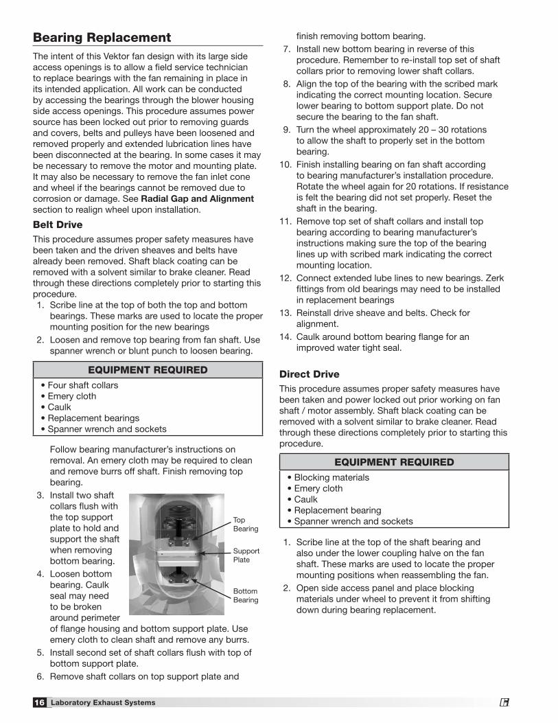
Belt DriveThis procedure assumes proper safety measures have been taken and the driven sheaves and belts have already been removed. Shaft black coating can be removed with a solvent similar to brake cleaner. Read through these directions completely prior to starting this procedure. 1. Scribe line at the top of both the top and bottom
bearings. These marks are used to locate the proper mounting position for the new bearings
2. Loosen and remove top bearing from fan shaft. Use spanner wrench or blunt punch to loosen bearing.
Follow bearing manufacturer’s instructions on removal. An emery cloth may be required to clean and remove burrs off shaft. Finish removing top bearing.
3. Install two shaft collars flush with the top support plate to hold and support the shaft when removing bottom bearing.
4. Loosen bottom bearing. Caulk seal may need to be broken around perimeter of flange housing and bottom support plate. Use emery cloth to clean shaft and remove any burrs.
5. Install second set of shaft collars flush with top of bottom support plate.
6. Remove shaft collars on top support plate and
Top Bearing
Support Plate
Bottom Bearing
EQUIPMENT REQUIRED • Four shaft collars • Emery cloth • Caulk • Replacement bearings • Spanner wrench and sockets
finish removing bottom bearing. 7. Install new bottom bearing in reverse of this
procedure. Remember to re-install top set of shaft collars prior to removing lower shaft collars.
8. Align the top of the bearing with the scribed mark indicating the correct mounting location. Secure lower bearing to bottom support plate. Do not secure the bearing to the fan shaft.
9. Turn the wheel approximately 20 – 30 rotations to allow the shaft to properly set in the bottom bearing.
10. Finish installing bearing on fan shaft according to bearing manufacturer’s installation procedure. Rotate the wheel again for 20 rotations. If resistance is felt the bearing did not set properly. Reset the shaft in the bearing.
11. Remove top set of shaft collars and install top bearing according to bearing manufacturer’s instructions making sure the top of the bearing lines up with scribed mark indicating the correct mounting location.
12. Connect extended lube lines to new bearings. Zerk fittings from old bearings may need to be installed in replacement bearings
13. Reinstall drive sheave and belts. Check for alignment.
14. Caulk around bottom bearing flange for an improved water tight seal.
Direct DriveThis procedure assumes proper safety measures have been taken and power locked out prior working on fan shaft / motor assembly. Shaft black coating can be removed with a solvent similar to brake cleaner. Read through these directions completely prior to starting this procedure.
1. Scribe line at the top of the shaft bearing and also under the lower coupling halve on the fan shaft. These marks are used to locate the proper mounting positions when reassembling the fan.
2. Open side access panel and place blocking materials under wheel to prevent it from shifting down during bearing replacement.
EQUIPMENT REQUIRED • Blocking materials • Emery cloth • Caulk • Replacement bearing • Spanner wrench and sockets
16 Laboratory Exhaust Systems®

Jib Crane Assembly (Optional Accessory)
The jib crane is mounted to sockets provided on the plenum housing. When assembling the jib crane, use the socket closest to the fan which is to be serviced (multiple sockets are on plenums consisting of three or more fans). Jib crane is designed to lift windband and motor only. Any other use may result in serious injury. Jib crane must not be used to lift the fan from the plenum.
NOTEComplete assembly instructions for the jib crane are documented in Assembly Instruction #472081, Jib Crane for Vektor. Instructions are shipped with the jib crane or can be found on greenheck.com
3. Remove coupling assembly from fan shaft. Upper coupling bushing may need to be removed and / or motor might also need to be tilted to remove old bearing and install new bearing. Coupling mounting locations should be scribed on any component loosened or removed.
4. Loosen and remove bearing from fan shaft. Follow bearing manufacturer’s instructions on removal. Caulk seal may need to be broken around perimeter of flange housing and bottom support plate. Use an emery cloth to clean and remove any burrs on fan shaft.
5. Slide new bearing onto fan shaft, but do not tighten to fan shaft
6. Reinstall coupling bushings and flex pack to fan shaft and motor shaft. This should be done according to manufacturer’s instructions making sure the components line up with scribed mark(s) indicating the correct mounting location.
7. Remove blocking from under fan wheel. 8. Turn the wheel approximately 20 – 30 rotations to
allow the shaft to properly set in the bearing and alignment between motor shaft and fan shaft.
9. Finish installing bearing on fan shaft according to bearing manufacturer’s installation procedure. Rotate the wheel again for 20 rotations. If resistance is felt the bearing did not set properly. Reset the shaft in the bearing.
10. Connect extended lube lines to new bearings. Zerk fittings from old bearings may need to be installed in replacement bearings. Purge non-synthetic grease from new bearing.
11. Caulk around bottom bearing flange for an improved water tight seal.
Shaft Bearing
Coupling
17Laboratory Exhaust Systems®

High Strength Metal Disc Coupling Installation and AlignmentDirect DriveCheck for misalignment between the two coupling hubs. The three types of misalignment (parallel, angular, and separation gap) are illustrated below. To minimize misalignment between the hubs, a straight edge can be used as a quick guide in aligning the shafts.
The Vektor direct drive single shaft bearing permits the shaft to swivel and essentially eliminates parallel misalignment.
But an excessive angle in the fan shaft will cause a higher degree of angular misalignment. It is best to have the motor shaft and fan shaft as close to parallel as possible. The coupling provided allows up to one degree of angular misalignment between the two joining hubs. No lubrication of the coupling is required.
Refer to the coupling manufacturer’s information / installation instruction sheet provided with the fan for additional details. Coupling should not be installed to support the weight of the fan shaft and wheel.
Parallel
Angular
Separation
Radial Gap and AlignmentEfficient fan performance can be maintained by having the correct radial gap and alignment. These items should be checked before start-up when the unit has been disassembled.
Straight Edge
Wheel Cone
Inlet Cone
Radial Gap: Adjust inlet cone position such that the radial gap between the wheel cone and inlet cone is evenly distributed around the wheel.
Alignment: If necessary, adjust wheel position by loosening the wheel hub from the fan shaft so that a straight edge held tight to the wheel cone just touches the inlet cone.
Radial Gap
Motor Change-Out Procedure Direct DriveTo remove the motor:
1. Install jib crane* in plenum mounting socket using Greenheck supplied hardware.
2. Position jib crane boom above windband. 3. Utilizing windband lifting lugs, rig windband to jib
crane cable. 4. Remove all bolts used to secure windband to
nozzle. 5. Lift off windband and lower to rooftop. 6. Reposition jib crane boom above fan. 7. Lower jib crane cable through center of fan until it
reaches the motor. 8. Remove bolts securing the motor to its horizontal
mounting plate. 9. Decouple motor shaft from wheel shaft by
disassembling coupling. 10. Rig motor to jib crane cable. 11. Lift motor out of fan body and lower to rooftop.
To install the new motor:
1. Rig new motor to jib crane cable. 2. Attach coupling half to motor shaft. Make sure
coupling hub is flush with the end of the motor shaft.
3. Position motor above fan body and carefully lower to its intended mounting position.
4. Ensure motor is positioned correctly so mounting bolts can be re-installed.
5. Install all coupling bolts to attach the motor shaft to the fan wheel shaft.
6. Install all bolts to attach motor to fan body mounting plate.
The Vektor fan was designed to ensure that when the new motor is installed, the relative angular alignment of the motor shaft to fan wheel shaft will be within +/-1 degree.
*If jib crane was not supplied with the Vektor system, a portable crane or hoist can be used.
18 Laboratory Exhaust Systems®
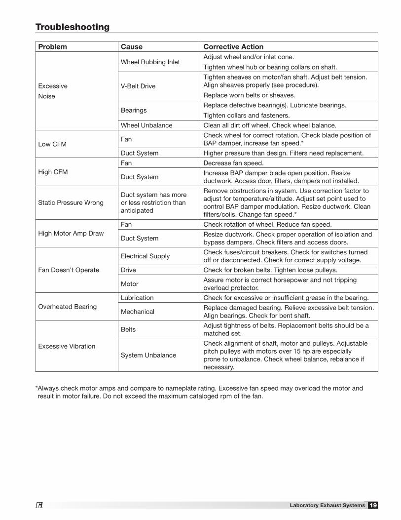
* AIways check motor amps and compare to nameplate rating. Excessive fan speed may overload the motor and result in motor failure. Do not exceed the maximum cataloged rpm of the fan.
Troubleshooting
Problem Cause Corrective Action
Excessive
Noise
Wheel Rubbing InletAdjust wheel and/or inlet cone.
Tighten wheel hub or bearing collars on shaft.
V-Belt DriveTighten sheaves on motor/fan shaft. Adjust belt tension. Align sheaves properly (see procedure).
Replace worn belts or sheaves.
BearingsReplace defective bearing(s). Lubricate bearings.
Tighten collars and fasteners.
Wheel Unbalance Clean all dirt off wheel. Check wheel balance.
Low CFMFan
Check wheel for correct rotation. Check blade position of BAP damper, increase fan speed.*
Duct System Higher pressure than design. Filters need replacement.
High CFMFan Decrease fan speed.
Duct SystemIncrease BAP damper blade open position. Resize ductwork. Access door, filters, dampers not installed.
Static Pressure WrongDuct system has more or less restriction than anticipated
Remove obstructions in system. Use correction factor to adjust for temperature/altitude. Adjust set point used to control BAP damper modulation. Resize ductwork. Clean filters/coils. Change fan speed.*
High Motor Amp DrawFan Check rotation of wheel. Reduce fan speed.
Duct SystemResize ductwork. Check proper operation of isolation and bypass dampers. Check filters and access doors.
Fan Doesn’t Operate
Electrical SupplyCheck fuses/circuit breakers. Check for switches turned off or disconnected. Check for correct supply voltage.
Drive Check for broken belts. Tighten loose pulleys.
MotorAssure motor is correct horsepower and not tripping overload protector.
Overheated BearingLubrication Check for excessive or insufficient grease in the bearing.
MechanicalReplace damaged bearing. Relieve excessive belt tension. Align bearings. Check for bent shaft.
Excessive Vibration
BeltsAdjust tightness of belts. Replacement belts should be a matched set.
System Unbalance
Check alignment of shaft, motor and pulleys. Adjustable pitch pulleys with motors over 15 hp are especially prone to unbalance. Check wheel balance, rebalance if necessary.
19Laboratory Exhaust Systems®

Vektor-MS Nozzle Parts and Assembly
DESCRIPTIONQTYITEMTRANSITION WELD21TRANSITION SIDE COVER22WIND WRAP ROUND23WIND WRAP FLAT24FRAME BOTTOM BAR25FRAME TOP BAR26FRAME WELD27BLADE WELD28ACTUATOR MOUNT2*9LIFT LUG410ACTUATOR COVER2*11BLADE SEAL RIGHT212BLADE SEAL LEFT613FLEX BACKING414VEKTOR BACKING215ACTUATOR2*16ELECTRICAL BOX117BEARING418BLADE SEAL419FLEX SEAL220
12
3
4
5
6
7
8
9
10
11
12
13
1415
16
17
18
19
20
*Quantity 1 for sizes 9 thru 13 Quantity 2 for sizes 16 thru 36
September 2013 -
Dan Jore instructed to use the Vektor-HS Nozzle Drawing for the Vektor-MS Installation Instruction.Changed item 9, 11, and 16 quantity from 1 or 2 to 2 or 4
Item Quantity Description
1 2 Transition Weld
2 2 Transition side cover
3 2 Wind wrap round
4 2 Wind wrap flat
5 2 Frame bottom bar
6 2 Frame top bar
7 2 Frame weld
8 2 Blade weld
9 2 or 4* Actuator mount
10 4 Lifting lug
11 2 or 4* Actuator cover
12 2 Blade seal, right
13 6 Blade seal, left
14 4 Flex backing
15 2 Vektor backing
16 2 or 4* Actuator
17 1 Electrical box
18 4 Bearing
19 4 Blade seal
20 2 Flex seal
* Quantity 2 for sizes 15 thru 24 Quantity 4 for sizes 27 thru 40
20 464652 • Vektor-MH, MD and MS, Rev. 5, October 2013 Copyright 2013 © Greenheck Fan Corporation
As a result of our commitment to continuous improvement, Greenheck reserves the right to change specifications without notice.
Specific Greenheck product warranties are located on greenheck.com within the product area tabs and in the Library under Warranties.
Greenheck Vektor MD and MH catalog provides additional information describing the equipment, fan performance, available accessories, and specification data.
®
Phone: 715.359.6171 • Fax: 715.355.2399 • Parts: 800.355.5354 • E-mail: [email protected] • Website: www.greenheck.com
Our Commitment
AMCA Publication 410-96, Safety Practices for Users and Installers of Industrial and Commercial Fans, provides additional safety information. This publication can be obtained from AMCA International, Inc. at www.amca.org.