installation, operation, and maintenance - trane · and maintenance important: proper execution of...
TRANSCRIPT

SAFETY WARNINGOnly qualified personnel should install and service the equipment. The installation, starting up, and servicing of heating, ventilating, and air-conditioning equipment can be hazardous and requires specific knowledge and training. Improperly installed, adjusted or altered equipment by an unqualified person could result in death or serious injury. When working on the equipment, observe all precautions in the literature and on the tags, stickers, and labels that are attached to the equipment.
Installation, Operation,
and Maintenance
Important: Proper execution of the tasks outlined in this Installation, Operation, and Maintenance manual require and assume the technician has been certified as a start up technician for the Horizon Outdoor Air unit. This includes working knowledge of the Tracer TU program.
Horizon™ Outdoor Air Unit
Indirect Gas-Fired/Electric Heat and Air Source Heat PumpModels: OABD, OABE, OAGD, OAGE
October 2016 OAU-SVX02D-EN

Introduction
Read this manual thoroughly before operating or servicing this unit.
Warnings, Cautions, and Notices
Safety advisories appear throughout this manual as required. Your personal safety and the proper operation of this machine depend upon the strict observance of these precautions.
Important Environmental Concerns
Scientific research has shown that certain man-made chemicals can affect the earth’s naturally occurring stratospheric ozone layer when released to the atmosphere. In particular, several of the identified chemicals that may affect the ozone layer are refrigerants that contain Chlorine, Fluorine and Carbon (CFCs) and those containing Hydrogen, Chlorine, Fluorine and Carbon (HCFCs). Not all refrigerants containing these compounds have the same potential impact to the environment. Trane advocates the responsible handling of all refrigerants-including industry replacements for CFCs such as HCFCs and HFCs.
Important Responsible Refrigerant Practices
Trane believes that responsible refrigerant practices are important to the environment, our customers, and the air conditioning industry. All technicians who handle refrigerants must be certified. The Federal Clean Air Act (Section 608) sets forth the requirements for handling, reclaiming, recovering and recycling of certain refrigerants and the equipment that is used in these service procedures. In addition, some states or municipalities may have additional requirements that must also be adhered to for responsible management of refrigerants. Know the applicable laws and follow them.
The three types of advisories are defined as follows:
WARNINGIndicates a potentially hazardous situation which, if not avoided, could result in death or serious injury.
CAUTIONsIndicates a potentially hazardous situation which, if not avoided, could result in minor or moderate injury. It could also be used to alert against unsafe practices.
NOTICE: Indicates a situation that could result in equipment or property-damage only accidents.
WARNING
Proper Field Wiring and Grounding Required!
Failure to follow code could result in death or serious injury. All field wiring MUST be performed by qualified personnel. Improperly installed and grounded field wiring poses FIRE and ELECTROCUTION hazards. To avoid these hazards, you MUST follow requirements for field wiring installation and grounding as described in NEC and your local/state electrical codes.
WARNING
Personal Protective Equipment (PPE) Required!
Failure to wear proper PPE for the job being undertaken could result in death or serious injury. Technicians, in order to protect themselves from potential electrical, mechanical, and chemical hazards, MUST follow precautions in this manual and on the tags, stickers, and labels, as well as the instructions below:
• Before installing/servicing this unit, technicians
MUST put on all PPE required for the work being
undertaken (Examples; cut resistant gloves/sleeves,
butyl gloves, safety glasses, hard hat/bump cap, fall
protection, electrical PPE and arc flash clothing).
ALWAYS refer to appropriate Material Safety Data
Sheets (MSDS)/Safety Data Sheets (SDS) and OSHA
guidelines for proper PPE.
• When working with or around hazardous chemicals,
ALWAYS refer to the appropriate MSDS/SDS and
OSHA/GHS (Global Harmonized System of
Classification and Labelling of Chemicals) guidelines
for information on allowable personal exposure
levels, proper respiratory protection and handling
instructions.
• If there is a risk of energized electrical contact, arc, or
flash, technicians MUST put on all PPE in accordance
with OSHA, NFPA 70E, or other country-specific
requirements for arc flash protection, PRIOR to
servicing the unit. NEVER PERFORM ANY
SWITCHING, DISCONNECTING, OR VOLTAGE
TESTING WITHOUT PROPER ELECTRICAL PPE AND
ARC FLASH CLOTHING. ENSURE ELECTRICAL
METERS AND EQUIPMENT ARE PROPERLY RATED
FOR INTENDED VOLTAGE.
© 2016 Ingersoll Rand All rights reserved OAU-SVX02D-EN

Introduction
Copyright
This document and the information in it are the property of Trane, and may not be used or reproduced in whole or in part without written permission. Trane reserves the right to revise this publication at any time, and to make changes to its content without obligation to notify any person of such revision or change.
Trademarks
All trademarks referenced in this document are the trademarks of their respective owners.
Revision History
• Model number updates
• Running edits
WARNING
Refrigerant under High Pressure!
Failure to follow instructions below could result in an explosion which could result in death or serious injury or equipment damage. System contains oil and refrigerant under high pressure. Recover refrigerant to relieve pressure before opening the system. See unit nameplate for refrigerant type. Do not use non-approved refrigerants, refrigerant substitutes, or refrigerant additives.
WARNING
Hazard of Explosion and Deadly Gases!
Failure to follow all proper safe refrigerant handling practices could result in death or serious injury. Never solder, braze or weld on refrigerant lines or any unit components that are above atmospheric pressure or where refrigerant may be present. Always remove refrigerant by following the guidelines established by the EPA Federal Clean Air Act or other state or local codes as appropriate. After refrigerant removal, use dry nitrogen to bring system back to atmospheric pressure before opening system for repairs. Mixtures of refrigerants and air under pressure may become combustible in the presence of an ignition source leading to an explosion. Excessive heat from soldering, brazing or welding with refrigerant vapors present can form highly toxic gases and extremely corrosive acids.
OAU-SVX02D-EN 3

Table of Contents
Model Number Descriptions . . . . . . . . . . . . . . 6
Horizon Outdoor Air Unit . . . . . . . . . . . . . . . 6
Models: OABD, OAGD . . . . . . . . . . . . . . . . 6
Models: OADD, OADE, OAKD, OAKE, OAND, OANE . . . . . . . . . . . . . . . . . . . . . . . . . . . . . . 9
General Information . . . . . . . . . . . . . . . . . . . . 12
Overview of Manual . . . . . . . . . . . . . . . . . 12
Model Number Description . . . . . . . . . . . 12
Unit Nameplate . . . . . . . . . . . . . . . . . . . . 12
Compressor Nameplate . . . . . . . . . . . . . . 12
Unit Description . . . . . . . . . . . . . . . . . . . . 12
Indoor Fan Failure Input . . . . . . . . . . . . . 12
Low Pressure Control ReliaTel Control . 12
Refrigerant Circuits . . . . . . . . . . . . . . . . . 12
High Pressure Control ReliaTel Control . 12
Space Temperature / RH Sensor (Optional) . . . . . . . . . . . . . . . . . . . . . . . . . . . . . . . . . . 13
High Temperature Sensor . . . . . . . . . . . . 13
Outdoor Air Temperature and Relative Hu-midity Sensor . . . . . . . . . . . . . . . . . . . . . . 13
Control Input (Occupied / Unoccupied) . 13
Hot Gas Reheat . . . . . . . . . . . . . . . . . . . . . 13
100 Percent Outdoor Air Hood with Damper and Filters . . . . . . . . . . . . . . . . . . . . . . . . . 13
Modulating Indirect Gas-Fired Burner . . 13
Through the Base Electrical with Disconnect Switch . . . . . . . . . . . . . . . . . . . . . . . . . . . . 13
Through the Base Gas Piping . . . . . . . . . 13
Hinged Access Doors . . . . . . . . . . . . . . . . 13
Electric Heat . . . . . . . . . . . . . . . . . . . . . . . 13
Unit Inspection . . . . . . . . . . . . . . . . . . . . . . . 14
First Aid Measures . . . . . . . . . . . . . . . . . . 14
Storage . . . . . . . . . . . . . . . . . . . . . . . . . . . 14
Unit Clearances . . . . . . . . . . . . . . . . . . . . 14
Unit Clearances, Curb Dimensions, and Dimen-sional Data . . . . . . . . . . . . . . . . . . . . . . . . . . . . . 15
OAB Units . . . . . . . . . . . . . . . . . . . . . . . . . 15
Indirect-Fired OAG Units . . . . . . . . . . . . . 17
Unit Weight and Rigging . . . . . . . . . . . . . . . . 20
Unit Weight . . . . . . . . . . . . . . . . . . . . . . . . 20
Corner Weight . . . . . . . . . . . . . . . . . . . . . .20
Rigging . . . . . . . . . . . . . . . . . . . . . . . . . . . .21
Sequence of Operation . . . . . . . . . . . . . . . . . . .22
Space Control with Indirect Fired Gas or Elec-tric Heat and Modulating HGRH, ERV, and Powered Ex. . . . . . . . . . . . . . . . . . . . . . . . . . .22
Sequence of Operation—”Occupied” . . .22
Sequence of Operation—”Unoccupied” .25
Discharge Air Control with Indirect Fired Gas or Electric Heat and Modulating HGRH, ERV, and Powered Ex. . . . . . . . . . . . . . . . . . . . . . .26
Sequence of Operation—”Occupied” . . .26
Sequence of Operation—”Unoccupied” .29
Single Zone VAV with Indirect Fired Gas or Electric Heat and Modulating HGRH, ERV, and Powered Ex. (Not Available with Heat Pump Units) . . . . . . . . . . . . . . . . . . . . . . . . . . . . . . . .30
Sequence of Operation—”Occupied” . . .30
Sequence of Operation—”Unoccupied” .32
Multi Zone VAV with Indirect Fired Gas or Electric Heat and Modulating HGRH, ERV, and Powered Ex. (Not Available with Heat Pump Units) . . . . . . . . . . . . . . . . . . . . . . . . . . . . . . . .34
Sequence of Operation—”Occupied” . . .34
Sequence of Operation—”Unoccupied” .35
Installation . . . . . . . . . . . . . . . . . . . . . . . . . . . . . .37
Ductwork . . . . . . . . . . . . . . . . . . . . . . . . . . .37
General Unit Requirements . . . . . . . . . . . .37
OAB and OAG IF Heater Air Inlet Hood and Flue Assembly Instructions . . . . . . . . . . . .38
Main Electrical Power Requirements . . . .40
Condensate Drain Configuration . . . . . . .40
Hot Water Control Valve Wiring . . . . . . . .40
Chilled Water Connection Size and Location . . . . . . . . . . . . . . . . . . . . . . . . . . . . . . . . . . .41
Filter Installation . . . . . . . . . . . . . . . . . . . . .41
Opening the Collapsed Exhaust Damper Hood . . . . . . . . . . . . . . . . . . . . . . . . . . . . . .41
Field Installed Power Wiring . . . . . . . . . . .43
Main Unit Power . . . . . . . . . . . . . . . . . . . . . .43
Standard Wiring . . . . . . . . . . . . . . . . . . . . .44
Voltage Imbalance . . . . . . . . . . . . . . . . . . .44
4 OAU-SVX02D-EN

Table of Contents
Electrical Phasing (Three-Phase Motors) 45
Compressor Crankcase Heaters . . . . . . . 45
Main Unit Display and ReliaTel Controls 45
Field-Installed Control Wiring . . . . . . . . . 46
Control Power Transformer . . . . . . . . . . . 46
Controls Using 24 Vac . . . . . . . . . . . . . . . 46
Controls Using DC Analog Input/Output (Standard Low Voltage Multiconductor Wire) . . . . . . . . . . . . . . . . . . . . . . . . . . . . . . . . . . 46
DC Conductors . . . . . . . . . . . . . . . . . . . . . . . 47
Factory-Provided Sensors . . . . . . . . . . . . . 47
Pre-Start Check List . . . . . . . . . . . . . . . . . . . . . 48
System Configuration and Pre-Start . . . . . . 49
Startup . . . . . . . . . . . . . . . . . . . . . . . . . . . . . . . . 52
Indirect Gas-Fired Heating Startup . . . . . . 52
Startup Procedure . . . . . . . . . . . . . . . . . . 52
Safety Controls . . . . . . . . . . . . . . . . . . . . . 55
Maintenance . . . . . . . . . . . . . . . . . . . . . . . . . . . 56
Monthly Maintenance . . . . . . . . . . . . . . . . . 56
Filters . . . . . . . . . . . . . . . . . . . . . . . . . . . . . 56
Supply/Return Air Smoke Detector Mainte-nance . . . . . . . . . . . . . . . . . . . . . . . . . . . . . 56
Cooling Season . . . . . . . . . . . . . . . . . . . . 56
Heating Season . . . . . . . . . . . . . . . . . . . . 56
Condenser Coil Cleaning . . . . . . . . . . . . . 56
Final Process . . . . . . . . . . . . . . . . . . . . . . . . . 58
Performance Data . . . . . . . . . . . . . . . . . . . . . . 59
Superheat and Refrigeration Circuit Data 63
Alarms and Troubleshooting . . . . . . . . . . . . 65
Microprocessor Control . . . . . . . . . . . . . . 65
System Alarms . . . . . . . . . . . . . . . . . . . . . 65
Sensor Failure Alarm Display . . . . . . . . . 65
RTRM Failure Modes . . . . . . . . . . . . . . . . 67
Appendix . . . . . . . . . . . . . . . . . . . . . . . . . . . . . . 68
OAU Filter Guide . . . . . . . . . . . . . . . . . . . . . 68
Field Installation of Factory-Provided Sensors . . . . . . . . . . . . . . . . . . . . . . . . . . . . . . . . . . . . . 69
Horizon™ Dedicated Outdoor Air Unit Startup Form . . . . . . . . . . . . . . . . . . . . . . . . . . . . . . . . 73
OAU-SVX02D-EN 5

Model Number Descriptions
Horizon Outdoor Air Unit
Models: OABD, OAGD
Digit 1, 2 — Unit TypeOA = Outdoor Air
Digit 3 — Cabinet SizeB = 500 cfm–3000 cfmG = 1250 cfm–7500 cfm
Digit 4 — Major Design SequenceD = Revision 1E = Heat Pump
Digit 5, 6, 7 — Normal Gross Cooling Capacity (MBh)000= No Cooling036 = 3 Tons High Efficiency048 = 4 Tons High Efficiency060 = 5 Tons High Efficiency072 = 6 Tons High Efficiency084 = 7 Tons High Efficiency096 = 8 Tons High Efficiency108 = 9 Tons High Efficiency120 = 10 Tons High Efficiency144 = 12 Tons High Efficiency180 = 15 Tons High Efficiency210 = 17 Tons High Efficiency240 = 20 Tons High Efficiency264 = 22 Tons High Efficiency300 = 25 Tons High Efficiency360 = 30 Tons High Efficiency
Digit 8 — Minor Design SequenceA = Vertical Discharge/Vertical ReturnB = Vertical Discharge/Horizontal
ReturnC = Horizontal Discharge/Vertical
ReturnD = Horizontal Discharge/Horizontal
ReturnE = Vertical Discharge/No ReturnF = Horizontal Discharge/No Return
Digit 9 — Voltage Selection3 = 208-230/60/34 = 460/60/35 = 575/60/3
Digit 10 — Reserved for Future Use
Digit 11 — Evaporator Type0 = No CoolingC = DX 4-Row InterlacedD = DX 6-Row InterlacedF = Glycol/Chilled Water
Digit 12 — Hot Gas Reheat0 = No HGRH1 = Fin and Tube Modulating2 = Fin and Tube On/Off3 = Microchannel Modulating4 = Microchannel On/Off
Digit 13 — Compressor0 = No CompressorsA = Scroll CompressorsB = Digital Scroll (1st Circuit Only)C = Digital Scroll (1st and 2nd Circuit)D = Variable Speed Scroll (1st
Circuit Only)E = Variable Speed Scroll (1st and
2nd Circuit)F = Scroll Compressors w/Sound
Attenuation PackageG = Digital Scroll (1st Circuit Only)
w/Sound Attenuation PackageH = Digital Scroll (1st and 2nd Circuit)
w/Sound Attenuation PackageJ = Variable Speed Scroll (1st Circuit
Only) w/Sound Attenuation Package
K = Variable Speed Scroll (1st and 2nd Circuit) w/Sound Attenuation Package
Digit 14 — Condenser0 = No Condenser1 = Air-Cooled Fin and Tube2 = Air-Cooled Fin and Tube
w/Head Pressure On/Off Control3 = Water-Cooled DX Condenser
Copper/Steel4 = Air-Cooled Fin and Tube
w/Head Pressure Variable Speed5 = Air-Cooled Microchannel 6 = Air-Cooled Microchannel
w/Head Pressure On/Off Control7 = Air-Cooled Microchannel
Variable Speed8 = Water-Cooled DX Condenser
Copper/Nickel
Digit 15 — Refrigerant Capacity Control0 = No RCC ValveA = RCC Valve on 1st CircuitB = RCC Valve on 1st and 2nd CircuitC = ERCC Valve on1st CircuitD = ERCC Valve on 1st and 2nd CircuitE = HGBP Valve on 1st CircuitF = HGBP Valve on 1st and
2nd Circuit
Digit 16 — Indoor Fan Motor (IFM)0 = ECM w/Backward Curved
Plenum Fan2 = Belt Drive3 = Belt Drive w/VFD4 = Special Motor Option
Digit 17 — Indoor Fan WheelA = 355B = 450 X 2C = 12/9 (Single Belt Drive)D = 12/9 BT (Dual Belt Drive)
Digit 18 — Indoor Fan Motor (hp)
Digit 19 — Reserved for Future Use
Digit 20 — Heater Type (PRI/SEC)0 = No HeatA = Indirect-Fired (IF)B = Direct-Fired (DF)C = Electric—4-StageD = Electric—SCR ModulatingE = Dual Fuel (PRI-IF/SEC-DF)F = Dual Fuel (PRI-ELEC/SEC-DF)G = Dual Fuel (PRI-IF/SEC-ELEC)H = Dual Fuel (PRI-ELEC/SEC-ELEC)J = Hot WaterK = SteamL = No Primary Heat,
Secondary ELECM = Dual Fuel
(PRI-ELEC-STAGED/SEC-DF)N = Dual Fuel
(PRI-ELEC-STAGED/SEC-ELEC)P = Dual Fuel (PRI-HW/SEC-DF)Q = Dual Fuel (PRI-HW/
SEC-ELEC-SCR)R = Dual Fuel (PRI-STEAM/SEC-DF)S = Dual Fuel (PRI-STEAM/SEC-
ELEC-SCR)
Digit 21 — Primary Fuel Type0 = No Heat1 = Natural Gas2 = Propane3 = Electric—Open Coil4 = Electric—Sheathed Coil5 = Hot Water6 = Steam
ECM Belt DriveA = 1 kW 2 hp
B = 2 kW 3 hp
C = 3 kW 5 hp
D = 4 kW 7.5 hp
E = 10 hp
F = 15 hp
6 OAU-SVX02D-EN

Model Number Descriptions
Digit 22 — Heater Capacity—Primary Heat Source
Digit 23 — Heat Capacity—Secondary Heat Source
Digit 24 — Corrosive Environment Package0 = No Corrosive Package1 = S/S Interior, S/S Evap Coil Casing2 = S/S Interior, Eco-Coated Coils3 = S/S Interior,
Copper/Copper Evap Coil4 = S/S Coil Casing5 = S/S Interior6 = Eco-Coated Coils7 = S/S Coil Casing with
Eco-Coated Coils8 = Copper/Copper Evap, HGRH
Coils9 = Corrosion Resistant Package
Digit 25, 26 — Unit Controls00 = Non DDC—ElectromechanicalAA = Trane—Discharge Air Control
w/LON Read-Write w/DisplayAB = Trane—Space Control w/LON
Read-Write w/DisplayAC = Trane—Discharge Air Control
w/BACnet® (No Display)AD = Trane—Space Control
w/BACnet (No Display)AF = Trane—Discharge Air Control
w/BACnet w/DisplayAG = Trane—Space Control
w/BACnet w/DisplayAI = Trane—Discharge Air Control
w/LON Read-Write (No Display)AJ = Trane—Space Control
w/LON Read-Write (No Display)AK = Trane—Multi-Zone VAV Control
w/LON Read-Write w/DisplayAL = Trane—Multi-Zone VAV Control
w/BACnet w/DisplayAM = Trane—Multi-Zone VAV Control
w/LON Read-Write (No Display)AN = Trane—Multi-Zone VAV Control
w/BACnet (No Display)AO = Trane—Single-Zone VAV Control
w/LON Read-Write w/DisplayAP = Trane—Single-Zone VAV Control
w/BACnet w/DisplayAQ = Trane—Single-Zone VAV Control
w/LON Read-Write (No Display)AR = Trane—Single-Zone VAV Control
w/BACnet (No Display)XX = Special
Digit 27 — Powered Exhaust Fan Motor (PFM) and Exhaust Dampers0 = No Powered Exhaust3 = Belt Drive4 = Belt Drive w/VFD5 = Special Motor Option6 = ECM w/Backward Curved
Plenum Fan7 = ECM w/Backward Curved
Plenum Fan and Barometric Relief Damper
8 = ECM w/Backward Curved Plenum Fan and Isolation Dampers w/End Switch
9 = Barometric Relief Dampers (No PFM)
Digit 28 — Powered Exhaust Fan Wheel0 = No Powered ExhaustA = 355B = 450C = 450 X 2D = 12/9 BT (single fan-belt drive)E = 12/9 BT (dual fan-belt drive)
Digit 29 — Powered Exhaust Fan Motor (hp)
DIGIT 30 — Reserved for Future Use
Digit 31 — ERV (Requires Powered Exhaust)0 = No ERVA = ERV—Composite Construction
w/BypassB = ERV—Composite Construction
with Frost Protection w/VFDC = ERV—Aluminum Construction
w/BypassD = ERV—Aluminum Construction
with Frost Protection w/VFD
Digit 32 — ERV Size0 = No ERV1 = 30142 = 36223 = 41364 = 46345 = 5856
Digit 33 — Damper Options0 = 100% OA 2-Position Damper1 = 100% OA 2-Position Damper
w/RA 2-Position Damper2 = Modulating OA and RA Dampers
w/Economizer
Digit 34 — Filtration OptionsA = No FiltersB = MERV-8, 30%C = MERV-13, 80%D = MERV-14, 95%E = MERV-8 30%, MERV-13 80%F = MERV-8 30%, MERV-14 95%G = MERV-8, 30%, with UVCH = MERV-13, 80%, with UVCJ = MERV-14, 95%, with UVCK = MERV-8 30%, MERV-13 80%,
and UVCL = MERV-8 30%, MERV-14 95%,
and UVCX = Special Filter Options
Digit 35 — Smoke Detector—Factory Installed0 = No Smoke Detector1 = Supply Smoke Detector2 = Return Smoke Detector3 = Supply and Return Smoke
Detectors
IF ELEC HOT WATER0 = No Heat No Heat No Heat
A = 50 MBh 5 kW 1 Row/10 FPI
B = 75 MBh 10 kW 1 Row/12 FPI
C = 100 MBh 15 kW 1 Row/14 FPI
D = 125 MBh 20 kW 2 Row/10 FPI
E = 150 MBh 24 kW 2 Row/12 FPI
F = 200 MBh 28 kW 2 Row/14 FPI
G = 250 MBh 32 kW 3 Row/10 FPI
H = 300 MBh 40 kW 3 Row/12 FPI
J = 350 MBh 48 kW 3 Row/14 FPI
K = 400 MBh 60 kW
L = 500 MBh 68 kW
M = 600 MBh 79 kW
N = 99 kW
O = 111 kW
P = 119 kW
X = Special Heater Option
ELEC DF0 = No Heat/No Secondary Heat
A = 5 kW 6 in. Burner—Up to 330 MBh
B = 10 kW 12 in. Burner—Up to 400 MBh
C = 15 kW 12 in. Burner—Up to 600 MBh
D = 20 kW 18 in. Burner—Up to 400 MBh
E = 24 kW 18 in. Burner—Up to 900 MBh
F = 28 kW
G = 32 kW
H = 40 kW
J = 48 kW
ECM Belt Drive0 = No Powered Exhaust
A = 1 kW 2 hp
B = 2 kW 3 hp
C = 3 kW 5 hp
D = 4 kW 7.5 hp
E = 10 hp
F = 15 hp
OAU-SVX02D-EN 7

Model Number Descriptions
Digit 36 — Electrical Options0 = Terminal BlockA = Non-Fused DisconnectB = Fused Disconnect SwitchC = Non-Fused Disconnect
w/Convenience OutletD = Fused Disconnect Switch
w/Convenience OutletE = Dual Point PowerF = Dual Point Power
w/Convenience OutletG = 65 SCCR Electrical Rating
w/Non-Fused DisconnectH = 65 SCCR Electrical Rating
w/Fused Disconnect J = 65 KAIC Electrical Rating
w/Non-Fused DisconnectK = 65 KAIC Electrical Rating
w/Fused DisconnectL = 65 KAIC Non-Fused
w/Convenience OutletM = 65 KAIC Fused
w/Convenience OutletN = 65 SCCR Non-Fused
w/Convenience Outlet
Digit 37 — Air Flow Monitoring0 = No Airflow Monitoring1 = Airflow Monitoring—IFM
Piezo Ring2 = Airflow Monitoring—PE
Piezo Ring3 = Airflow Monitoring—Outdoor Air
with Display and IFM w/Piezo Ring
4 = Airflow Monitoring—IFM Piezo Ring and PE Piezo Ring
5 = Airflow Monitoring—Outdoor Air Monitoring w/Display Supply Air and Exhaust Air w/Piezo Rings
Digit 38 — Accessories0 = No OptionsA = HailguardsB = Hailguards and LED Service
Light in Supply Fan SectionD = Hailguards & LED Service Light
in Exhaust Fan SectionE = Hailguards & LED Service Light
in Supply and Exhaust Fan Section
Digit 39 — Altitude0 = Sea Level to 1,000 feet1 = 1,001 to 2,000 feet2 = 2,001 to 3,000 feet3 = 3,001 to 4,000 feet4 = 4,001 to 5,000 feet5 = 5,001 to 6,000 feet6 = 6,001 to 7,000 feet7 = Above 7,000 feet
8 OAU-SVX02D-EN

Model Number Descriptions
Models: OADD, OADE, OAKD, OAKE, OAND, OANE
Digit 1, 2 — Unit TypeOA = Outdoor Air
Digit 3 — Cabinet SizeD = 625 cfm–4,000 cfmK = 1,500 cfm–9,000 cfmN = 3,750 cfm–13,500 cfm
Digit 4 — Major Design SequenceD = Revision 5E = Heat Pump
Digit 5, 6, 7 — Normal Gross Cooling Capacity (MBh)000= No Cooling060 = 5 Tons High Efficiency072 = 6 Tons High Efficiency084 = 7 Tons High Efficiency096 = 8 Tons High Efficiency120 = 10 Tons High Efficiency144 = 12 Tons High Efficiency180 = 15 Tons High Efficiency210 = 17 Tons High Efficiency240 = 20 Tons High Efficiency264 = 22 Tons High Efficiency300 = 25 Tons High Efficiency360 = 30 Tons High Efficiency420 = 35 Tons High Efficiency480 = 40 Tons High Efficiency540 = 45 Tons High Efficiency600 = 50 Tons High Efficiency648 = 54 Tons High Efficiency
Digit 8 — Minor Design SequenceA = Vertical Discharge/Vertical ReturnB = Vertical Discharge/
Horizontal ReturnC = Horizontal Discharge/
Vertical ReturnD = Horizontal Discharge/
Horizontal ReturnE = Vertical Discharge/No Return
Digit 9 — Voltage Selection3 = 208-230/60/34 = 460/60/35 = 575/60/3
Digit 10 — Reserved for Future Use
Digit 11 — Evaporator Type0 = No CoolingC = DX 4-Row InterlacedD = DX 6-Row InterlacedF = Glycol/Chilled Water Coil
Digit 12 — Hot Gas Reheat0 = No HGRH1 = Fin and Tube Modulating2 = Fin and Tube On/Off3 = Microchannel Modulating4 = Microchannel On/Off
Digit 13 — Compressor0 = No CompressorsA = Scroll CompressorsB = Digital Scroll (1st Circuit Only)C = Digital Scroll (1st and 2nd Circuit)D = Variable Speed Scroll (1st
Circuit Only)E = Variable Speed Scroll (1st and
2nd Circuit)F = Scroll Compressors w/Sound
Attenuation PackageG = Digital Scroll (1st Circuit Only)
w/Sound Attenuation PackageH = Digital Scroll (1st and 2nd Circuit)
w/Sound Attenuation PackageJ = Variable Speed Scroll (1st Circuit
Only) w/Sound Attenuation Package
K = Variable Speed Scroll (1st and 2nd Circuit w/Sound Attenuation Package
Digit 14 — Condenser0 = No Condenser1 = Air-Cooled Fin and Tube2 = Air-Cooled Fin and Tube
w/Head Pressure On/Off Control3 = Water-Cooled DX Condenser
Copper/Steel4 = Air-Cooled Fin and Tube
w/Head Pressure Variable Speed5 = Air-Cooled Microchannel6 = Air-Cooled Microchannel
w/Head Pressure On/Off Control7 = Air-Cooled Microchannel
Variable Speed8 = Water-Cooled DX Condenser
Copper/Nickel
Digit 15 — Refrigerant Capacity Control0 = No RCC ValveA = RCC Valve on 1st CircuitB = RCC Valve on 1st and 2nd CircuitC = ERCC Valve on1st CircuitD = ERCC Valve on 1st and 2nd CircuitE = HGBP Valve on 1st CircuitF = HGBP Valve on 1st and
2nd Circuit
Digit 16 — Indoor Fan Motor (IFM)0 = Direct Drive w/VFD1 = Direct Drive (VFD by Others)2 = Belt Drive3 = Belt Drive w/VFD4 = Direct Drive w/Shaft
Grounding Ring w/VFD5 = Special Motor Option
Digit 17 — Indoor Fan WheelA = 120B = 120.6C = 140D = 140.6E = 160F = 160.6G = 180H = 180.6J = 200K = 200.6L = 180 X 2M = 180.6 X 2
Digit 18 — Indoor Fan Motor HPA = 1/2 hp—1800 rpmB = 1/2 hp—3600 rpmC = 3/4 hp—1800 rpmD = 3/4 hp—3600 rpmE = 1 hp—1800 rpmF = 1 hp—3600 rpmG = 1.5 hp—1800 rpmH = 1.5 hp—3600 rpmJ = 2 hp—1800 rpmK = 2 hp—3600 rpmL = 3 hp—1800 rpmM = 3 hp—3600 rpmN = 5 hp—1800 rpmP = 5 hp—3600 rpmR = 7.5 hp—1800 rpmS = 7.5 hp—3600 rpmT = 10 hp—1800 rpmU = 10 hp—3600 rpmV = 15 hp—1800 rpmW = 15 hp—3600 rpm
Digit 19 — Reserved for Future Use
Digit 20 — Heat Type (PRI/SEC)0 = No HeatA = Indirect-Fired (IF)B = Direct-Fired(DF)C = Electric—4-StageD = Electric—SCR ModulatingE = Dual Fuel (PRI-IF/SEC-DF)F = Dual Fuel (PRI-ELEC/SEC-DF)G = Dual Fuel (PRI-IF/SEC-ELEC)H = Dual Fuel (PRI-ELEC/SEC-ELEC)J = Hot WaterK = SteamL = No Primary Heat,
Secondary ELECM = Dual Fuel
(PRI-ELEC-STAGED/SEC-DF)N = Dual Fuel
(PRI-ELEC-STAGED/SEC-ELEC)P = Dual Fuel (PRI-HW/SEC-DF)Q = Dual Fuel
(PRI-HW/SEC-ELEC-SCR)R = Dual Fuel (PRI-STEAM/SEC-DF)S = Dual Fuel
(PRI-STEAM/SEC-ELEC-SCR)
OAU-SVX02D-EN 9

Model Number Descriptions
Digit 21 — Primary Fuel Type0 = No Heat1 = Natural Gas2 = Propane3 = Electric—Open Coil4 = Electric—Sheathed Coil5 = Hot Water6 = Steam
Digit 22 — Heat Capacity—Primary Heat Source
Digit 23 — Heat Capacity—Secondary Heat Source
Digit 24 — Corrosive Environment Package0 = No Corrosive Package1 = S/S Interior, S/S Evap Coil Casing2 = S/S Interior, Eco-Coated Coils3 = S/S Interior,
Copper/Copper Evap Coil4 = S/S Coil Casing5 = S/S Interior6 = Eco-Coated Coils7 = S/S Coil Casing with
Eco-Coated Coils8 = Copper/Copper Evap,
HGRH Coils9 = Corrosion Resistant Package
Digit 25, 26 — Unit Controls00 = Non DDC—ElectromechanicalAA = Trane—Discharge Air Control
w/LON Read-Write w/DisplayAB = Trane—Space Control
w/LON Read-Write w/DisplayAC = Trane—Discharge Air Control
w/BACnet® (No Display)AD = Trane—Space Control
w/BACnet (No Display)AF = Trane—Discharge Air Control
w/BACnet w/DisplayAG = Trane—Space Control
w/BACnet w/DisplayAI = Trane—Discharge Air Control
w/LON Read-Write (No Display)AJ = Trane—Space Control
w/LON Read-Write (No Display)AK = Trane—Multi-Zone VAV Control
w/LON Read-Write w/ DisplayAL = Trane—Multi-Zone VAV Control
w/BACnet w/DisplayAM = Trane—Multi-Zone VAV Control
w/LON Read-Write (No Display)AN = Trane—Multi-Zone VAV Control
w/BACnet (No Display)AO = Trane—Single-Zone VAV Control
w/Lon Read-Write w/DisplayAP = Trane—Single-Zone VAV Control
w/BACnet w/DisplayAQ = Trane—Single-Zone VAV Control
w/LON Read-Write (No Display)AR = Trane—Single-Zone VAV Control
w/BACnet (No Display)
Digit 27 — Powered Exhaust Fan Motor (PFM) and Exhaust Dampers0 = No Powered Exhaust1 = Direct Drive w/VFD and
Gravity Dampers2 = Direct Drive (VFD by Others)3 = Belt Drive4 = Belt Drive w/VFD5 = Special Motor Option6 = Direct Drive w/VFD and
Barometric Relief Damper7 = Direct Drive w/VFD and
Isolation Dampers w/End Switch8 = Barometric Relief Dampers
(No PFM)
Digit 28 — Powered Exhaust Fan Wheel0 = No Powered ExhaustA = 120B = 120.6C = 140D = 140.6E = 160F = 160.6G = 180H = 180.6J = 200K = 200.6L = 180 X 2M = 180.6 X 2
IF ELEC HOT WATER0 = No Heat No Heat No Heat
A = 50 MBh 10 kW 1 Row/10 FPI
B = 75 MBh 20 kW 1 Row/12 FPI
C = 100 MBh 24 kW 1 Row/14 FPI
D = 125 MBh 28 kW 2 Row/10 FPI
E = 150 MBh 32 kW 2 Row/12 FPI
F = 200 MBh 40 kW 2 Row/14 FPI
G = 250 MBh 48 kW 3 Row/10 FPI
H = 300 MBh 60 kW 3 Row/12 FPI
J = 350 MBh 68 kW 3 Row/14 FPI
K = 400 MBh 79 kW
L = 500 MBh 99 kW
M = 600 MBh 111 kW
N = 700 MBh 119 kW
P = 800 MBh 139 kW
R = 1000 MBh 159 kW
S = 179 kW
T = 199 kW
U = 215 kW
X = Special Heater Option
IF ELEC DF0 = No Heat/No Secondary Heat
A = 50 MBh 10 kW 6 in. Burner—Up to 330 MBh
B = 75 MBh 20 kW 12 in. Burner—Up to 400 MBh
C = 100 MBh 24 kW 12 in. Burner—Up to 600 MBh
D = 125 MBh 28 kW 18 in. Burner—Up to 400 MBh
E = 150 MBh 32 kW 18 in. Burner—Up to 900 MBh
F = 200 MBh 40 kW
G = 250 MBh 48 kW
H = 300 MBh 60 kW
J = 350 MBh 68 kW
K = 400 MBh 79 kW
L = 500 MBh 99 kW
M = 600 MBh 111 kW
N = 700 MBh 119 kW
P = 800 MBh 139 kW
R = 1000 MBh 159 kW
S = 179 kW
T = 199 kW
U = 215 kW
10 OAU-SVX02D-EN

Model Number Descriptions
Digit 29 — Powered Exhaust Fan Motor (hp)0 = No Powered ExhaustA = 1/2 hp—1800 rpmB = 1/2 hp—3600 rpmC = 3/4 hp—1800 rpmD = 3/4 hp—3600 rpmE = 1 hp—1800 rpmF = 1 hp—3600 rpmG = 1.5 hp—1800 rpmH = 1.5 hp—3600 rpmJ = 2 hp—1800 rpmK = 2 hp—3600 rpmL = 3 hp—1800 rpmM = 3 hp—3600 rpmN = 5 hp—1800 rpmP = 5 hp—3600 rpmR = 7.5 hp—1800 rpmS = 7.5 hp—3600 rpmT = 10 hp—1800 rpmU = 10 hp—3600 rpmV = 15 hp—1800 rpmW = 15 hp—3600 rpm
Digit 30 — Reserved for Future Use
Digit 31 — ERV (Requires Powered Exhaust)0 = No ERVA = ERV—Composite ConstructionB = ERV—Composite Construction
with Frost Protection w/VFDC = ERV—Composite Construction
with BypassD = ERV—Composite Construction
with Frost Protection and BypassE = ERV—Aluminum ConstructionF = ERV—Aluminum Construction
with Frost Protection w/VFDG = ERV—Aluminum Construction
with BypassH = ERV—Aluminum Construction
with Frost Protection and Bypass
Digit 32 — ERV Size0 = No ERV1 = 30142 = 36223 = 41364 = 46345 = 58566 = 64887 = 68768 = 74122
Digit 33 — Damper Options0 = 100% OA 2-Position Damper1 = 100% OA 2-Position Damper
w/RA 2-Position Damper2 = Modulating OA and RA Dampers
w/Economizer
Digit 34 — Filtration OptionsA = Aluminum Mesh Intake Filters
(ALM) B = MERV-8,30%, and ALMC = MERV-13, 80%, and ALMD = MERV-14, 95%, and ALME = MERV-8 30%, MERV-13 80%, and
ALMF = MERV-8 30%, MERV-14 95%, and
ALMG = MERV-8, 30%, and ALM, with
UVCH = MERV-13, 80%, and ALM, with
UVCJ = MERV-14, 95%, and ALM, with
UVCK = MERV-8 30%, MERV-13 80%,
ALM, and UVCL = MERV-8 30%, MERV-14 95%,
ALM, and UVCX = Special Filter Options
Digit 35 — Smoke Detector—Factory Installed0 = No Smoke Detector1 = Supply Smoke Detector2 = Return Smoke Detector3 = Supply and Return Smoke
Detector
Digit 36 — Electrical Options0 = Non-Fused DisconnectA = Fused Disconnect SwitchB = Non-Fused Disconnect
w/Convenience OutletC = Fused Disconnect Switch
w/Convenience OutletD = Dual Point Power
w/Convenience OutletF = 65 SCCR Electrical Rating
w/Non-Fused DisconnectG = 65 SCCR Electrical Rating
w/Fused Disconnect H = 65 KAIC Electrical Rating
w/Non-Fused DisconnectJ = 65 KAIC Electrical Rating
w/Fused DisconnectL = 65 KAIC Non-Fused
w/Convenience Outlet= 65 KAIC Fused
w/Convenience OutletN = 65 SCCR Non-Fused
w/Convenience Outlet
Digit 37 — Air Flow Monitoring0 = No Airflow Monitoring1 = Airflow Monitoring—IFM
Piezo Ring2 = Airflow Monitoring—PE
Piezo Ring3 = Airflow Monitoring—Outdoor Air
with Display and IFM w/Piezo Ring
4 = Airflow Monitoring—IFM Piezo Ring and PE Piezo Ring
5 = Airflow Monitoring—Outdoor Air Monitoring w/ Display Supply Air and Exhaust Air w/Piezo Rings
Digit 38 — Accessories0 = No OptionsA = HailguardsB = LED Service Light in Supply
Fan SectionC = Hailguards and LED Service
Light in Supply Fan SectionD = Hailguards and LED Service
Light in Exhaust Fan SectionE = Hailguards and LED Service
Light in Supply and Exhaust Fan Section
F = LED Service Light in Exhaust Fan Section
G = LED Service Light in Supply and Exhaust Fan Section
Digit 39 — Altitude0 = Sea Level to 1,000 feet1 = 1,001 to 2,000 feet2 = 2,001 to 3,000 feet3 = 3,001 to 4,000 feet4 = 4,001 to 5,000 feet5 = 5,001 to 6,000 feet6 = 6,001 to 7,000 feet7 = Above 7,000 feet
OAU-SVX02D-EN 11

General Information
Overview of Manual
Note: One copy of this document ships inside the control panel of each unit and is customer property. It must be retained by the unit’s maintenance personnel.
This booklet describes proper installation, operation, and maintenance procedures for air cooled systems. By carefully reviewing the information within this manual and following the instructions, the risk of improper operation and/or component damage will be minimized.
It is important that periodic maintenance be performed to help assure trouble free operation. A maintenance schedule is provided at the end of this manual. Should equipment failure occur, contact a qualified service organization with qualified, experienced HVAC technicians to properly diagnose and repair this equipment.
Model Number Description
All products are identified by a multiple-character model number that precisely identifies a particular type of unit. An explanation of the alphanumeric identification code is provided (see “Model Number Descriptions,” p. 6). Its use will enable the owner/operator, installing contractors, and service engineers to define the operation, specific components, and other options for any specific unit.
When ordering replacement parts or requesting service, be sure to refer to the specific model number and serial number printed on the unit nameplate.
Unit Nameplate
A Mylar® unit nameplate is located on the unit’s corner support next to the control box. It includes the unit model number, serial number, electrical characteristics, refrigerant charge, as well as other pertinent unit data.
Compressor Nameplate
The nameplate for the compressors are located on the side of the compressor.
Unit Description
Before shipment, each unit is leak tested, dehydrated, charged with refrigerant and compressor oil, and run tested for proper control operation.
The condenser coils are aluminum fin, mechanically bonded to copper tubing.
Direct-drive, vertical discharge condenser fans are provided with built-in thermal overload protection.
The Outdoor Air Unit Main Unit Display and ReliaTel™ Control Module (RTRM) are microelectronic control systems. The acronym RTRM is extensively throughout this document when referring to the control system network.
The Main Unit Display and the RTRM are mounted in the Main Control Panel. The Main Unit Display and RTRM
receive information from sensors and customer binary contacts to satisfy the applicable request for ventilation, cooling, dehumidification and heating.
Indoor Fan Failure Input
The Indoor Fan Failure Switch (IFFS) is connected to verify indoor fan operation.
When there is a call for the indoor fan to be energized, the differential pressure switch, connected to the Main Unit Display, must prove airflow within 60 seconds or the Main Unit Display will shut off all mechanical operations, lock the system out and send a diagnostic alarm to the Unit Display. The system will remain locked out until a reset is initiated through the MCM via the Alarm Reset Function on the Unit Display.
Low Pressure Control ReliaTel Control
This input incorporates the compressor low pressure control (CLP 1) for the refrigeration circuit and can be activated by opening a field supplied contact installed on the OAUTS.
If this circuit is open before the compressor is started, the ReliaTel™ control will not allow the affected compressor to operate. Anytime this circuit is opened for 1 continuous second during compressor operation, the compressor is immediately turned “Off.” The compressor will not be allowed to restart for a minimum of 3 minutes should the contacts close.
If four consecutive open conditions occur during the first three minutes of operation, the compressor will be locked out, and a manual reset will be required to restart the compressor.
Refrigerant Circuits
For 3–5 ton units, one refrigerant circuit shall incorporate a standard 4- -row coil. For 6–9 ton units, one refrigerant circuit shall incorporate a 4 or 6 row coil. For 10–30 ton units, two refrigerant circuits shall incorporate a 4- or 6-row coil. All circuits shall have thermal expansion valves (TXVs), service pressure ports, and refrigerant line filter driers as standard. An area will be provided for replacement suction line driers. Each refrigerant circuit is equipped with a factory installed and preset refrigerant capacity control (RCC) to prevent evaporator coil temperatures below approximately 38°F (114 lb suction). The refrigerant capacity device is not installed when the unit is equipped with a digital scroll.
High Pressure Control ReliaTel Control
The compressor high pressure controls (CHP 1) are wired in series between the compressor outputs on RTRM1 (CHP 1) and the compressor contactor coils. If one of the high pressure control switches opens, the RTRM senses a lack of current while calling for cooling and locks the compressor out.
12 OAU-SVX02D-EN
General Information
Space Temperature / RH Sensor (Optional)
Field installed, wall mounted temperature and humidity sensor (BAYSENS036A) to control space cooling, heating and dew point. Refer to “Space Control with Indirect Gas-Fired or Electric Heat and Modulating HGRH, ERV, and Powered Ex.,” p. 20 for specific details.
High Temperature Sensor
The Discharge Air Temperature Sensor (DTC) supplies a continuous signal to the MCM. Factory setting for Discharge Air Temperature (DTC) Discharge Air Temperature Setpoint (MDTS) is 90°F (adj 70–100°F), the unit will be shut down, and require a manual restart if Discharge Air Temperature exceeds MDTS for 10 minutes (adj 10–25 minutes). If DAT exceeds Discharge Air High Temperature Cutoff (DHCS) of 125°F for 10 minutes, the unit will shut down and require manual restart.
Outdoor Air Temperature and Relative Humidity Sensor
This factory installed combination outdoor air sensor located in the outdoor air hood is designed to sense both outdoor air temperature and relative humidity for use by the microprocessor controller to make required ventilation, cooling, dehumidification and heating decisions. Refer to “Sequence of Operation,” p. 20 for detailed unit control and operational modes.
Control Input (Occupied / Unoccupied)
Terminals are provided on the terminal strip labeled OAUTS for a field installed dry contact or switch closure to put the unit in the Occupied or Unoccupied modes.
Hot Gas Reheat
This option shall consist of a hot-gas reheat coil located on the leaving air side of the evaporator. Refer to the “Sequence of Operation,” p. 20 for detailed unit control and operational modes.
100 Percent Outdoor Air Hood with Damper and Filters
Factory-installed and -integrated 100 percent outdoor air hood with damper controlled by a direct coupled actuator. The unit can be factory provided with an optional 100 percent return air damper controlled by a direct coupled actuator that is electrically interlocked with the outdoor air damper.
Modulating Indirect Gas-Fired Burner
The unit will have fully modulating, high turndown, indirect gas-fired heat. The heating section will include high turn-down burners and a stainless steel tubular heat exchanger. The heat exchanger will be constructed of type 439 stainless steel and be a tubular design capable of draining internal condensate. External flue to be constructed of type 430 stainless steel.
Units will be suitable for use with natural gas or Liquid Propane (LP) gas.
Through the Base Electrical with Disconnect Switch
An optional factory installed 3-pole, molded case disconnect switch with provisions for through the base electrical connections may be included. The disconnect switch, with integral overcurrent circuit breaker, will be installed in the unit in a water tight enclosure with access through a hinged door. Factory wiring will be provided from the switch to the unit high voltage terminal block. The switch will be UL/CSA agency recognized.
Through the Base Gas Piping
The unit will include provisions for installing through the base gas piping. The factory installed option will have all piping necessary including an external shutoff piping yoke with pre-assembled, manual gas shut-off valve, elbows, and union. The manual shut-off valve will include an 1/8 in. (3.17 mm) NPT pressure tap. This assembly will require minor field labor to install.
Hinged Access Doors
Hinged access doors with hold open brackets will be factory-installed.
Electric Heat
The unit may have four stage or fully modulating SCR controlled, electric heat. The primary heating section will include open coil heating elements, automatic and manual cut-outs, low voltage controls, air proving switch, maximum 48 amps per circuit and fusing for heaters over 48 amps.
OAU-SVX02D-EN 13
General Information
Unit Inspection
As soon as the unit arrives at the job site:
• Avoid breathing fiberglass dust.
• Use a NIOSH approved dust/mist respirator.
• Avoid contact with the skin or eyes. Wear long-sleeved, loose-fitting clothing, gloves, and eye protection.
• Wash clothes separately from other clothing: rinse washer thoroughly.
• Operations such as sawing, blowing, tear-out, and spraying may generate fiber concentrations requiring additional respiratory protection. Use the appropriate NIOSH approved respiration in these situations.
First Aid Measures
Eye Contact
Flush eyes with water to remove dust. If symptoms persist, seek medical attention.
Skin Contact
Wash affected areas gently with soap and warm water after handling.
Storage
Take precautions to prevent condensate from forming inside the unit’s electrical compartments and motors if:
• the unit is stored before it is installed; or,
• the unit is set on the roof curb, and temporary heat is provided in the building. Isolate all side panel service entrances and base pan openings (e.g., conduit holes, S/A and R/A openings, and flue openings) from the ambient air until the unit is ready for startup.
Note: Do not use the unit’s heater for temporary heat without first completing the startup procedure detailed in “Startup,” p. 52.
The manufacturer will not assume any responsibility for equipment damage resulting from condensate accumulation on the unit’s electrical and/or mechanical components.
Unit Clearances
“Unit Clearances, Curb Dimensions, and Dimensional Data,” p. 15 contains figures that illustrate the minimum operating and service clearances for either a single or multiple unit installation. These clearances are the minimum distances necessary to assure adequate serviceability, cataloged unit capacity, and peak operating efficiency.
Providing less than the recommended clearances may result in condenser coil starvation, “short-circuiting” of exhaust or recirculation of hot condenser air.
WARNING
Fiberglass Wool!
Product may contain fiberglass wool. Disturbing the insulation in this product during installation, maintenance or repair will expose you to airborne particles of glass wool fibers and ceramic fibers known to the state of California to cause cancer through inhalation. Glass wool fibers may also cause respiratory, skin or eye irritation.
Verify that the nameplate data matches the data on the sales order and bill of lading (including electrical data).
Verify that the power supply complies with the unit nameplate specifications.
Visually inspect the exterior of the unit, including the roof, for signs of shipping damage.
Visually inspect the internal components for shipping damage as soon as possible after delivery and before it is stored. Do not walk on the sheet metal base pans.
If concealed damage is discovered, notify the carrier’s terminal of damage immediately by phone and by mail. Concealed damage must be reported within 15 days.
Request an immediate joint inspection of the damage by the carrier and the consignee. Do not remove damaged material from the receiving location. Take photos of the damage, if possible. The owner must provide reasonable evidence that the damage did not occur after delivery.
Notify the appropriate sales representative before installing or repairing a damaged unit.
14 OAU-SVX02D-EN

Unit Clearances, Curb Dimensions, and Dimensional
Data
OAB Units
Unit Clearances
Note: Certain options require auxiliary cabinet. Refer to project-specific unit submittals.
Curb Dimensions
WARNING
Combustible Materials!
Failure to maintain proper clearance between the unit heat exchanger, vent surfaces and combustible materials could cause a fire which could result in death or serious injury or property damage. Refer to unit nameplate and installation instructions for proper clearances.
Figure 1. Typical installation clearances for OAB unit
7'-0" 6'-0"
END TO END
3'-0"
4'-0"
4'-0"
3'-0"
Figure 2. Typical installation clearances for OAB unit
with auxiliary cabinet
Figure 3. Unit curb data for OAB 3–9 tons
OAU-SVX02D-EN 15

Unit Clearances, Curb Dimensions, and Dimensional Data
Note: Certain options require auxiliary cabinet. Refer to project-specific unit submittals.
Dimensional Data
Note: Sound attenuation package will add 17.76 in. to the height of the condenser fan section. Refer to project-specific unit submittals.
Figure 4. Unit curb data for OAB 3–9 tons with
auxiliary cabinetFigure 5. Unit dimensional data for OAB 3–9 tons (in.)
16 OAU-SVX02D-EN

Unit Clearances, Curb Dimensions, and Dimensional Data
Note: Certain options require auxiliary cabinet. Refer to project-specific unit submittals.
Note: Sound attenuation package will add 17.76 in. to the height of the condenser fan section. Refer to project-specific unit submittals.
Indirect-Fired OAG Units
Unit Clearances
Figure 6. Unit dimensional data for OAB 3–9 tons with
auxiliary cabinet (in.)
Figure 7. Typical installation clearances for indirect-
fired OAG unit
KCCInternational Inc.
72"
84"
36"
KCCInternational Inc.
36" 48"
36"
OAU-SVX02D-EN 17

Unit Clearances, Curb Dimensions, and Dimensional Data
KCCInternational Inc.
Note: Certain options require auxiliary cabinet. Refer to project-specific unit submittals.
Curb Dimensions
Note: Certain options require auxiliary cabinet. Refer to project-specific unit submittals.
Dimensional Data
Figure 8. Typical installation clearances for indirect-
fired OAG unit with auxiliary cabinet
Figure 9. Unit curb data for indirect-fired OAG (in.)
KCCInternational Inc.
72"
84"
36"
48" 36"
36"
SUPPLY
KCCInternational Inc.
RETURN
4 13 3
55"
4 19 3 "
3
"
" 23 4
3
53"
8 4
3 " 8 4
1 " 70 2
1
"
" 117 2
25 12 "
Figure 10. Unit curb data for indirect-fired OAG with
auxiliary cabinet (in.)
Figure 11. Unit dimensional data for indirect-fired OAG
RETURN
2 44 1 "
8 4 "3
23 4
4
3 "
" 8
53"
3
8 165 5 "
1 " 70 2
1
"
" 117 2
3
55"
13 4
3 " 19 4
1 " 25 2
5 " 3 8
3 12 "
KCCInternational Inc.
SUPPLY
17.250
35.798
ELECTRICDISCONNECT
FRONT VIEW 77.524
67.060
74.000
74.417
3.226
KCCInternational Inc.
CNECT
RIGHT SIDE VIEW
121.000 32.573 6.084 6.914
13.039
159.656
22.463
BOTTOM VIEW
17.250
5.125
22.000
24.500SUPPLY
4.000
19.955RETURN
11.000
52.000RETURN
11.000
4.000
54.000SUPPLY
2.000 THROUGHBASE ELECTRIC
KCC
18 OAU-SVX02D-ENInternational Inc.
Unit Clearances, Curb Dimensions, and Dimensional Data
Note: Sound attenuation package will add 10.79 in. to the height of the condenser fan section. Refer to project-specific unit submittals.
Note: Certain options require auxiliary cabinet. Refer to project-specific unit submittals.
Note: Sound attenuation package will add 10.79 in. to the height of the condenser fan section. Refer to project-specific unit submittals.
Figure 12. Unit dimensional data for indirect-fired OAG
with auxiliary cabinet
17.250
35.798
ELECTRICDISCONNECT
FRONT VIEW 77.524
67.060
74.000
74.417
3.226
6.914
13.039
6.084
17.250
2.000 THROUGHBASE ELECTRIC
BOTTOM VIEW 5.125
22.000 24.500SUPPLY 52.072 19.955
RETURN
11.000
52.000RETURN
11.000
4.000
54.000SUPPLY
RIGHT SIDE VIEW
121.000 48.072 32.585 3.039
40.595
207.740 169.072
OAU-SVX02D-EN 19

Unit Weight and Rigging
Unit WeightCorner Weight
WARNING
Heavy Objects!
Failure to follow instructions below or properly lift unit could result in unit dropping and possibly crushing operator/technician which could result in death or serious injury, and equipment or property-only damage. Ensure that all the lifting equipment used is properly rated for the weight of the unit being lifted. Each of the cables (chains or slings), hooks, and shackles used to lift the unit must be capable of supporting the entire weight of the unit. Lifting cables (chains or slings) may not be of the same length. Adjust as necessary for even unit lift.
WARNING
Improper Unit Lift!
Failure to properly lift unit could result in unit dropping and possibly crushing operator/technician which could result in death or serious injury, and equipment or property-only damage. Test lift unit approximately 24 inches to verify proper center of gravity lift point. To avoid dropping of unit, reposition lifting point if unit is not level.
Table 1. Typical unit weight and center-of-gravity (CG)—units without auxiliary cabinet
Model Number
Operating Weight (lb)
Shipping Weight (lb)
Center-of-gravity (in.)
Min Max Min Max Length Width
OAB*036* 1255 1439 1503 1687 26 43.5
OAB*048* 1255 1439 1503 1687 26 43.5
OAB*060* 1255 1439 1503 1687 26 43.5
OAB*072* 1295 1479 1543 1727 26 43.5
OAB*084* 1295 1479 1543 1727 26 43.5
OAB*096* 1295 1479 1543 1727 26 43.5
OAB*108* 1336 1520 1584 1768 26 43.5
OAG*120* 2559 4012 2559 4012 N/A N/A
OAG*144* 2559 4063 2559 4063 N/A N/A
OAG*180* 2559 4113 2559 4113 N/A N/A
OAG*210* 2567 4243 2567 4243 N/A N/A
OAG*240* 2567 4294 2567 4294 N/A N/A
OAG*264* 2567 4294 2567 4294 N/A N/A
OAG*300* 2822 4546 2822 4546 N/A N/A
Note: Minimum and maximum weights vary widely due to the highly configurable nature of the product.
Table 2. Typical unit weight and center-of-gravity (CG)—units with auxiliary cabinet
Model Number
Operating Weight (lb)
Shipping Weight (lb)
Center-of-gravity (in.)
Min Max Min Max Length Width
OAB*036* 1740 2054 2048 2362 26 68
OAB*048* 1740 2054 2048 2362 26 68
OAB*060* 1740 2054 2048 2362 26 68
OAB*072* 1780 2094 2088 2402 26 68
OAB*084* 1780 2094 2088 2402 26 68
OAB*096* 1780 2094 2088 2402 26 68
OAB*108* 1821 2135 2129 2443 26 68
OAG*120* 3879 4012 3879 4012 N/A N/A
OAG*144* 3879 4281 3879 4281 N/A N/A
OAG*180* 3879 4281 3879 4281 N/A N/A
OAG*210* 3887 4289 3887 4289 N/A N/A
OAG*240* 3887 4294 3887 4294 N/A N/A
OAG*264* 3887 4294 3887 4294 N/A N/A
OAG*300* 4058 4546 4058 4546 N/A N/A
Note: Minimum and maximum weights vary widely due to the highly configurable nature of the product.
Table 3. Corner weights (percent of total weight)
Cabinet Size
Percentage (%)
Corner A Corner B Corner C Corner D
OAB* without auxiliary cabinet 21.3 31.9 21.4 25.4
OAB* with auxiliary cabinet 24.1 29.5 22.0 24.4
OAG* without auxiliary cabinet 25.0 29.8 21.1 24.1
OAG* with auxiliary cabinet 28.0 25.4 23.1 23.5
Note: Actual corner weights will vary depending on components selected.
Figure 13. Cabinet corners
OAB and OAG CabinetsBA
INTAKEHOOD
CD
20 OAU-SVX02D-EN

Unit Weight and Rigging
Rigging
Before proceeding, refer to Table 1, p. 20 and Table 2, p. 20 for typical unit operating weights and Figure 14, p. 21 for rigging drawing.
1. Remove the shipping crate from around the unit.
2. Rig the unit as shown in Figure 14, p. 21. Attach adequate strength lifting slings to all four lifting brackets in the unit base rail. Do not use cables, chains, or slings except as shown.
3. Install a lifting bar, as shown in Figure 14, p. 21, to protect the unit and to facilitate a uniform lift. The minimum distance between the lifting hook and the top of the unit should be 7 feet.
4. Test-lift the unit to ensure it is properly rigged and balanced, make any necessary rigging adjustments.
5. Lift the unit and position it into place. Remove fork pockets prior to setting on the curb.
6. Downflow units; align the base rail of the unit with the curb rail while lowering the unit onto the curb. Make sure that the gasket on the curb is not damaged while positioning the unit.
Figure 14. Rigging and center-of-gravity data
4-point liftModel: OAB
6-point liftModel: OAB
Figure 14. Rigging and center-of-gravity data
SPREADERBARS
A
DETAIL ASCALE 1 : 12
SCREW PIN SHACKLE4 LOCATIONS
KCCInternational Inc.
4-point liftModel: OAG
KCCInternational Inc.
A
SPREADERBARS
SCALE 1 : 12DETAIL A
SCREW PIN SHACKLE4 LOCATIONS
6-point liftModel: OAG
OAU-SVX02D-EN 21

Sequence of Operation
Space Control with Indirect Fired
Gas or Electric Heat and
Modulating HGRH, ERV, and
Powered Ex.
Sequence of Operation—”Occupied”
Optional space temperature and/or humidity sensors must be installed, wired to unit, configured as “installed” at the main unit controller.
Emergency Stop. When the contacts at Terminal OAUTS 9 and 10 are open, the unit’s operation will be in Alarm Status. Unit will begin normal operation upon closure of OAUTS 9 and 10.
Important: Cycling power to unit to clear alarm may not resolve alarm condition.
Starting Sequence
When 3-phase is powered to the unit the main unit controller and the RTRM will initialize. Initialization process requires approximately 3 minutes. The unit is placed in occupied operation via either the BAS or by closing connection between unit terminals OAUTS 7 and 8. The unit must not be in lockout.
Starting Sequence with No Return Air Damper
Installed
The outdoor air damper will be commanded to open. The damper end switch will make causing the main unit controller to initialize the indoor fan starting sequence. If the unit is equipped with a VFD on the indoor fan(s) the sequence will begin by sending a preset run signal (field adjustable between 50 and 100 percent). If the unit is equipped with an ECM fan the sequence will begin by controlling to a field adjustable CFM setpoint. If after 30 seconds the indoor fan proving switch does not prove the indoor fan on, the main unit controller will command the indoor fan off and signal an alarm.
Starting Sequence with Optional Return Air
Damper Installed
Identical to sequence with no return air damper except the outdoor air and return air dampers will be commanded to move to their preset occupied positions. Outdoor air damper end switch is disabled when the return air damper is installed.
Operating Modes
A. Economizer
B. Ventilation
C. Heating
D. Dehumidification
E. Cooling
All modes are enabled by the main unit control module. The control module calculates dewpoint based on sensed air temperature and humidity.
A. Economizer Mode. Economizer is field adjustable between Enthalpy or Dry Bulb with the binary value Economizer Control Type (defaulted from factory as enthalpy).
Enthalpy Economizer
Modulating dampers are required for economizer. Economizer Mode is enabled based on outdoor air enthalpy, return air enthalpy and outdoor air temperature. Operation in economizer mode is enabled when the outdoor air enthalpy remains below return air enthalpy and continues until outdoor air enthalpy rises above return air enthalpy by 3 Btu/lb or when the outdoor air temperature rises above 80°F.
If the Outdoor Air Temperature is more than 5°F below the Occupied Space Cooling Setpoint then the DX cooling will be locked out and the dampers will modulate to maintain the Occupied Space Cooling Setpoint. If the Outdoor Air Temperature is above that point by a deadband of 1°F then the outdoor air damper shall open to the Maximum Damper Position and allow DX cooling to stage, as necessary.
Dry Bulb Economizer
Modulating dampers are required for economizer. Economizer Mode is enabled based on outdoor air temperature and return air temperature. Operation in economizer mode is enabled when the outdoor air temperature is below return air temperature and continues until conditions call for dehumidification or when the outdoor air temperature is above the return air temperature by 3°F.
If the Outdoor Air Temperature is more than 5°F below the Occupied Space Cooling Setpoint then the DX cooling will be locked out and the dampers will modulate to maintain the Occupied Space Cooling Setpoint. That lockout has a deadband of 1°F. If the Outdoor Air Temperature is above that point then the outdoor air damper will open to the Maximum Damper Position and allow DX cooling to stage, as necessary.
B. Ventilation Mode. Ventilation mode is enabled based on space temperature and outdoor air temperature. Operation in Ventilation Mode is enabled when the space temperature between the Occupied Space Cooling Setpoint and the Occupied Space Heating Setpoint, and the outdoor temperature is between the Outdoor Air Cooling Setpoint and the Outdoor Air Heating Setpoint. Operation in Ventilation Mode continues until conditions call for dehumidification or when the space and outdoor air temperature fall outside of those two conditions.
22 OAU-SVX02D-EN

Sequence of Operation
During Ventilation Mode, both cooling and heat will be locked out and the outdoor air damper will open to the Maximum Damper Position (if equipped with optional modulating dampers).
C. Heating Mode.
Non-heat Pump Units
Heating Mode is enabled based on Outdoor Air Heating Setpoint (OAHS), Occupied Space Heating Setpoint, and Occupied Space Cooling Setpoint. If the outdoor air temperature is lower than the OAHS then Heating Mode shall be enabled. If the outdoor air temperature is above the OAHS but the unit is not calling for cooling or dehumidification then the unit shall switch between Heating and Cooling Mode as necessary to maintain an average temperature of the Occupied Space Cooling Setpoint and the Occupied Space Heating Setpoint.
During Heating Mode the main unit controller will modulate the heating output to maintain the Occupied Space Heating Setpoint. Maximum discharge air heating temperature is adjustable but cannot exceed 125°F for gas heat and 90°F for electric heat. Hot gas reheat is disabled when heating is enabled.
Air Source Heat Pump Units
Heating mode is enabled based on Outdoor Air Heating Setpoint (OAHS), Occupied Space Heating Setpoint, and Occupied Space Cooling Setpoint. If the outdoor air temperature is lower than the OAHS then Heating Mode shall be enabled. If the outdoor air temperature is above the OAHS but the unit is not calling for cooling or dehumidification then the unit shall switch between Heating and Cooling Mode as necessary to maintain an average temperature of the Occupied Space Cooling Setpoint and the Occupied Space Heating Setpoint.
During Heating Mode Compressor 1 will be staged on. If after a 3-minute minimum delay the space temperature is still below the setpoint, the second, third, and fourth stages of heating (Compressors 2, 3, and 4) will be staged on sequentially following individual 3-minute minimum delays between each call. During operation in heating mode, the main unit controller will enable hot gas reheat at 100 percent.
Auxiliary Heating Mode will be enabled if the compressor heat is not able to maintain setpoint for more than 10 minutes or if the Outdoor Air Temperature is below 0°F. Auxiliary heating mode will disable the compressors from running and modulate the heating output to maintain the Occupied Space Heating Setpoint. Auxiliary heating mode will be disabled when the OAT rises 5°F above the temperature that it switched from DX heating to auxiliary heating. Maximum discharge air heating temperature is adjustable but cannot exceed 125°F for gas heat and 90°F for electric heat.
Demand Defrost Control is a similar sequence to the ReliaTel™ 3–10 Ton heat pump units. Outdoor coil defrosting occurs only when operating in DX heating
mode with outdoor ambient temperature below 52°F and the outdoor coil temperature below 35°F. The first defrost cycle after power-up is initiated based on 30 minutes operating time at the required conditions. Twelve minutes after completion of the defrost cycle, the temperature difference between the outdoor coil and outdoor air is calculated resulting in a Clean Coil Delta T (ΔT) and is used as an indicator of unit performance at dry coil conditions. Over time, as moisture and frost accumulate on the coil, the coil temperature will drop, increasing the temperature difference. When the temperature difference between the outdoor coil and outdoor air reaches 1.8 x ΔT, a defrost cycle is initiated. While defrosting, the reversing valve(s) are in the cooling position, outdoor fan(s) are off, outdoor damper closes, return damper opens, the supply fan runs at minimum, and the compressor(s) continue to operate. If the optional return damper is not installed, the outdoor damper will remain open. The defrost cycle is terminated when the coil temperature rises high enough to indicate that the frost has been eliminated. Termination of the defrost cycle includes a “soft start” delay. At the end of each defrost cycle, the outdoor fan comes on 5 seconds before the reversing valve is de-energized to reduce noise.
Water Source Heat Pump Units
Heating mode is enabled based on Outdoor Air Heating Setpoint (OAHS), Occupied Space Heating Setpoint, and Occupied Space Cooling Setpoint. If the outdoor air temperature is lower than the OAHS then Heating Mode shall be enabled. If the outdoor air temperature is above the OAHS but the unit is not calling for cooling or dehumidification then the unit shall switch between Heating and Cooling Mode as necessary to maintain an average temperature of the Occupied Space Cooling Setpoint and the Occupied Space Heating Setpoint.
During Heating Mode Compressor 1 will be staged on. If after a 3-minute minimum delay the space temperature is still below the setpoint, the second, third, and fourth stages of heating (Compressors 2, 3, and 4) will be staged on sequentially following individual 3-minute minimum delays between each call. During operation in heating mode, the main unit controller will enable hot gas reheat at 100 percent.
Auxiliary Heating Mode will be enabled if the Outdoor Air Temperature Active (if unit is equipped with optional ERV then the temperature will be after the ERV) falls below 0°F, the compressor heat is not able to maintain setpoint for more than 10 minutes, the Water Flow switch opens for more than 10 seconds, or the leaving water temperature falls below 35°F/20°F (water only/glycol). Auxiliary heating mode will disable the compressors from running and modulate the heating output to maintain the Occupied Space Heating Setpoint.
Auxiliary heating mode will be disabled when the Outdoor Air Temperature Active rises above 0°F, when the leaving water temperature rises above 51°F/35°F (water only/ glycol), and when the OAT rises 5°F above the temperature that it switched from DX heating to auxiliary heating.
OAU-SVX02D-EN 23

Sequence of Operation
Maximum discharge air heating temperature is adjustable but cannot exceed 125°F for gas heat and 90°F for electric heat. If no auxiliary heat is provided, unit will be disabled when the Outdoor Air Temperature Active falls below 0°F.
C. Dehumidification Mode. Dehumidification Mode is enabled on Outdoor Air Dewpoint Setpoint (OADS) or Space Dewpoint Setpoint (SPDS). If there is no call for Heating Mode and the outdoor air dewpoint is above or equal to the OADS or the space dewpoint is above or equal to the SPDS then Dehumidification Mode shall be enabled. Dehumidification Mode will remain active until the space or outdoor air dewpoints rise above the setpoints by 2°F, or if Heating Mode is enabled.
Compressor control is based on Evaporator Leaving Air Temperature Setpoint. With dehumidification enabled, if evaporator leaving air temperature is above setpoint first stage dehumidification (Compressor 1) will start. If after a 3-minute minimum delay the evaporator leaving air temperature is still above the setpoint, the second, third, and fourth stages of dehumidification (Compressor 2, 3, and 4) will be staged on sequentially following individual 3-minute minimum delays between each call. During operation in Dehumidification Mode, the main unit controller will enable hot gas reheat and it will modulate to maintain the Occupied Space Cooling Setpoint.
Hot Gas Reheat Purge
Following continuous 30-minute hot gas reheat operation at less than 100 percent reheat capacity a purge cycle will be initiated. During the purge cycle, the hot gas reheat signal is set and held at 100 percent for a period of 3 minutes. Following the purge cycle, normal operation resumes.
D. Cooling Mode. Cooling Mode is enabled based on Outdoor Air Cooling Setpoint (OACS), Occupied Space Heating Setpoint, and Occupied Space Cooling Setpoint. If the outdoor air temperature is above the OACS then Cooling Mode shall be enabled. If the outdoor air temperature is below the OACS but the unit is not calling for heating or dehumidification then the unit shall switch between Heating and Cooling Mode as necessary to maintain an average temperature of the Occupied Space Cooling Setpoint and the Occupied Space Heating Setpoint.
Compressor staging is identical to dehumidification; however, the control temperature is the Occupied Space Cooling Setpoint. Should the space temperature begin to fall too low, the hot gas reheat shall be enabled and modulate to maintain the Occupied Space Cooling Setpoint.
Optional Features
Space Thumbwheel Input
With a space thumbwheel installed (factory supplied, field installed), Occupied Space Heating Setpoint and Occupied Space Cooling Setpoint will be replaced with a single setpoint based on the input from the thumbwheel.
Digital Compressors
Main unit controller will modulate digital compressor to maintain either Evap Leaving Temp Setpoint or Occupied Space Cooling Setpoint depending on mode of operation. Remaining compressors will be staged as described in mode.
Variable Speed Compressors
Main unit controller will modulate variable speed compressor to maintain either Evap Leaving Temp Setpoint or Occupied Space Cooling Setpoint setpoints depending on mode of operation. Remaining compressors will be staged as described in mode.
Exhaust Fan Operation
Exhaust with Isolation Dampers
When the indoor fan operation has been proven and the unit is in occupied, there will be a call for the exhaust. When there is a call for the exhaust, the isolation dampers will be powered and the powered exhaust will be enabled once the end switch on the exhaust actuators are proven. If the unit is equipped with modulating dampers, the exhaust fan speed will modulate to maintain the Return Duct Pressure Setpoint (factory defaulted to 1 in. wc). If modulating dampers are not equipped, the exhaust will maintain a constant volume of airflow.
During Unoccupied, the powered exhaust will be shut off.
Exhaust with Gravity Dampers
When the indoor fan operation has been proven and the unit is in occupied, there will be a call for the exhaust. If the unit is equipped with modulating dampers, the exhaust fan speed will modulate to maintain the Return Duct Pressure Setpoint (factory defaulted to 1 in. wc). If modulating dampers are not equipped, the exhaust will maintain a constant volume of airflow.
During Unoccupied, the powered exhaust will be shut off.
Energy Wheel Operation
The ERV is interlocked with indoor fan and exhaust fan operation in occupied heating, dehumidification, or cooling modes. When operating in Economizer Mode or Ventilation Mode, the ERV is disabled and the ERV by-pass dampers will open, powered exhaust remains on. If Ventilation Mode or Economizer Mode has been enabled for 10 minutes, the ERV will be enabled for one minute. This cycle will repeat every 10 minutes. During Unoccupied, both the ERV and the powered exhaust will be shut off.
During ERV operation, if the Exhaust Temperature across the ERV drops below 25°F, the outdoor air bypass damper will start to slowly modulate open. If after the bypass dampers modulate to 100 percent open and the exhaust temp across the ERV drops below 15°F (2°F deadband) for 5 minutes, the unit controller will command the ERV off.
24 OAU-SVX02D-EN

Sequence of Operation
Optional Demand Control CO2 Ventilation
With CO2 sensor (field-supplied and -installed) and modulating damper option selected with the unit, the UC600 will look at the CO2 sensor value and compare it to the CO2 Setpoint. If the CO2 level in the space is higher than the setpoint, the UC600 will modulate the outdoor air damper open (PID loop in the controller is configurable) until the CO2 levels in the space are within the setpoint value. The UC600 will then close the OA damper (or minimum position based on the value in the PID loop) and wait for the space CO2 level to change again.
Optional Non-Heat Pump Head Pressure Control
The Trane Horizon™ OAU head pressure variable speed control option (if selected) allows increased reheat capacity and mechanical cooling for ambient conditions as low as 0°F. A temperature sensor on the header of the condenser coil will measure the liquid temperature. Variable frequency drives will adjust the speed of the condenser fan(s) as needed to maintain a condenser temperature of 105°F.
Water Source Heat Pump Head Pressure Control
When a call for cooling or dehumidification exists, the head pressure controller will be powered. The controller will modulate the normally open water valve to maintain a pre-determined refrigerant pressure setpoint of 400 psi of liquid pressure.
Optional Air Source Heat Pump Head Pressure
Control
The Trane Horizon™ OAU head pressure variable speed control option (if selected) allows increased reheat capacity and mechanical cooling for ambient conditions as low as 0°F. A pressure sensor on the liquid line will modulate the condenser fan(s) to maintain a pre-determined setpoint of 350 psi of liquid pressure.
Optional Space Pressure Control for Indoor Fan
With the optional binary value Space Pressure Input set as installed, the indoor fan will modulate to maintain space pressure based on the Universal Pressure Setpoint. The input can either be hardwired into Universal Pressure Local or written to the point Universal Pressure BAS.
Optional Secondary Pre-Heat
If an on/off pre-heater is installed, the heater will be enabled when the Outdoor Air Temperature is below a field selectable setpoint defaulted at 0°.
If a modulating pre-heater is installed, the heater will be enabled when the primary heat is at 100 percent capacity but is unable to maintain setpoint. Once the pre-heater is enabled the primary heat will remain at full capacity and the pre-heat will modulate to maintain Occupied Space Heating Setpoint. Pre-heat will be disabled if the heater is at 0 percent and the space is over setpoint for an extended period of time.
Sequence of Operation—”Unoccupied”
Emergency Stop. When the contacts at Terminal OAUTS 9 and 10 are open, the unit’s operation will be in Alarm Status. Unit will begin normal operation upon closure of OAUTS 9 and 10.
Starting Sequence
Indoor fan proving sequence is identical to occupied operation.
Starting Sequence with Optional Return Air
Damper Installed
The outdoor air damper will be commanded to close and the return air damper will open. Outdoor air damper end switch is disabled when the return air damper is installed.
Starting Sequence with No Return Air Damper
Installed. Identical to occupied sequence no return air damper installed.
Operating Modes
A. Unoccupied Heating
B. Unoccupied Dehumidification
C. Unoccupied Cooling
A. Heating Mode.
Non-heat Pump Units
Unoccupied heating is enabled based on UNOCC Space Heating Setpoint. Unoccupied heating is enabled when space temperature reaches unoccupied space heating setpoint + 2°F. The modulating gas heat or SCR electric heat will continue to raise the discharge air temperature to a maximum of 90°F and continue to supply heated 90°F air to the space until the space temperature reaches setpoint + 6°F. Unit operation is discontinued when unoccupied space heating is satisfied.
Heat Pump Units
Unoccupied heating is enabled based on UNOCC Space Heating Setpoint. Unoccupied heating is enabled when space temperature reaches unoccupied space heating setpoint + 2°F. The unit will continue to raise the discharge air temperature to a maximum of 90°F and continue to supply heated 90°F air to the space until the space temperature reaches setpoint + 4°F. Unit operation is discontinued when unoccupied space heating is satisfied.
Determination of heat pump operation or auxiliary heat operation is identical to Occupied Heating Mode.
B. Dehumidification Mode. When no call for unoccupied heating exists, unoccupied dehumidification is enabled based on UNOCC Space Dewpoint Setpoint. During unoccupied dehumidification operation dehumidification capacity is restricted to 50 percent (only half of the compressors are allowed to come on).
Unoccupied dehumidification is enabled when space dewpoint reaches UNOCC Space Dewpoint Setpoint + 1°F.
OAU-SVX02D-EN 25

Sequence of Operation
Dehumidification stops at setpoint - 1°F. Unit operation is discontinued when unoccupied space dehumidification is satisfied.
C. Cooling Mode. When no call for unoccupied heating or unoccupied dehumidification exists, unoccupied cooling is enabled based on UNOCC Space Cooling Setpoint. During unoccupied space cooling operation cooling capacity is restricted to 50 percent (only half of the compressors are allowed to come on). Unoccupied cooling is enabled when space temperature reaches unoccupied space cooling setpoint + 2°F. Cooling stops at setpoint - 2°F. Unit operation is discontinued when unoccupied space cooling is satisfied.
Powered Exhaust/ERV Sequence of Operation
Powered Exhaust/ERV operation is disabled during unit “Unoccupied” operating modes.
Discharge Air Control with
Indirect Fired Gas or Electric Heat
and Modulating HGRH, ERV, and
Powered Ex.
Sequence of Operation—”Occupied”
Emergency Stop. When the contacts at Terminal OAUTS 9 and 10 are open, the unit’s operation will be in Alarm Status. Unit will begin normal operation upon closure of OAUTS 9 and 10.
Important: Cycling power to unit to clear alarm may not resolve alarm condition.
Starting Sequence
When 3-phase is powered to the unit the main unit controller and the RTRM will initialize. Initialization process requires approximately 3 minutes. The unit is placed in occupied operation via either the BAS or by closing connection between unit terminals OAUTS 7 and 8. The unit must not be in lockout.
Starting Sequence with No Return Air Damper
Installed
The outdoor air damper will be commanded to open. The damper end switch will make causing the main unit controller to initialize the indoor fan starting sequence. If the unit is equipped with a VFD on the indoor fan(s) the sequence will begin by sending a preset run signal (field adjustable between 50 and 100 percent). If the unit is equipped with an ECM fan the sequence will begin by controlling to a field adjustable CFM setpoint. If after 30 seconds the indoor fan proving switch does not prove the indoor fan on, the main unit controller will command the indoor fan off and signal an alarm.
Starting Sequence with Optional Return Air
Damper Installed
Identical to sequence with no return air damper except the outdoor air and return air dampers will be commanded to move to their preset occupied positions. Outdoor air damper end switch is disabled when the return air damper is installed.
Operating Modes
A. Economizer
B. Ventilation
C. Heating
D. Dehumidification
E. Cooling
All modes are enabled by the main unit control module. The control module calculates dewpoint based on sensed outdoor air temperature and humidity.
26 OAU-SVX02D-EN

Sequence of Operation
A. Economizer Mode. Economizer is field adjustable between Enthalpy or Dry Bulb with the binary value Economizer Control Type (defaulted from factory as enthalpy).
Enthalpy Economizer
Modulating dampers are required for economizer. Economizer Mode is enabled based on outdoor air enthalpy, return air enthalpy and outdoor air temperature. Operation in economizer mode is enabled when the outdoor air enthalpy remains below return air enthalpy and continues until outdoor air enthalpy rises above return air enthalpy by 3 Btu/lb or when the outdoor air temperature rises above 80°F.
If the Outdoor Air Temperature is more than 5°F below the Discharge Air Cooling Setpoint, then the DX cooling will be locked out and the dampers will modulate to maintain the Discharge Air Cooling Setpoint. If the Outdoor Air Temperature is above that point by a deadband of 1°F, then the outdoor air damper shall open to the Maximum Damper Position and allow DX cooling to stage, as necessary.
Dry Bulb Economizer
Modulating dampers are required for economizer. Economizer Mode is enabled based on outdoor air temperature and return air temperature. Operation in economizer mode is enabled when the outdoor air temperature is below return air temperature and continues until conditions call for dehumidification or when the outdoor air temperature is above the return air temperature by 3°F.
If the Outdoor Air Temperature is more than 5°F below the Discharge Air Cooling Setpoint, then the DX cooling will be locked out and the dampers will modulate to maintain the Discharge Air Cooling Setpoint. That lockout has a deadband of 1°F. If the Outdoor Air Temperature is above that point, then the outdoor air damper will open to the Maximum Damper Position and allow DX cooling to stage, as necessary.
B. Ventilation Mode. Ventilation mode is enabled based on outdoor air temperature. Operation in Ventilation Mode is enabled when the outdoor temperature is between the Outdoor Air Cooling Setpoint and the Outdoor Air Heating Setpoint. Operation in Ventilation Mode continues until conditions call for dehumidification or when the outdoor air temperature fall outside of that condition.
During Ventilation Mode both cooling and heat will be locked out and the outdoor air damper will modulate to maintain the Discharge Air Cooling Setpoint (if equipped with optional modulating dampers).
C. Heating Mode.
Non-heat Pump Units
Heating mode is enabled based on Outdoor Air Heating Setpoint (OAHS). If the outdoor air temperature is lower than the OAHS, then Heating Mode shall be enabled.
During Heating Mode, the main unit controller will modulate the heating output to maintain the Discharge Air Heating Setpoint. Maximum discharge air heating temperature is adjustable but cannot exceed 125°F for gas heat and 90°F for electric heat. Hot gas reheat is disabled when heating is enabled.
Air Source Heat Pump Units
Heating mode is enabled based on Outdoor Air Heating Setpoint (OAHS) and Outdoor Air Cooling Setpoint (OACS). If the outdoor air temperature is lower than the OAHS, then Heating Mode shall be enabled.
During Heating Mode, Compressor 1 will be staged on. If after a 3-minute minimum delay the discharge temperature is still below the setpoint, the second, third, and fourth stages of heating (Compressors 2, 3, and 4) will be staged on sequentially following individual 3-minute minimum delays between each call. During operation in heating mode, the main unit controller will enable hot gas reheat at 100 percent.
Auxiliary Heating Mode will be enabled if the compressor heat is not able to maintain setpoint for more than 10 minutes or if the Outdoor Air Temperature is below 0°F. Auxiliary heating mode will disable the compressors from running and modulate the heating output to maintain the Discharge Air Heating Setpoint. Auxiliary heating mode will be disabled when the OAT rises 5°F above the temperature that it switched from DX heating to auxiliary heating. Maximum discharge air heating temperature is adjustable but cannot exceed 125°F for gas heat and 90°F for electric heat.
Demand Defrost Control is a similar sequence to the ReliaTel™ 3–10 Ton heat pump units. Outdoor coil defrosting occurs only when operating in DX heating mode with outdoor ambient temperature below 52°F and the outdoor coil temperature below 35°F. The first defrost cycle after power-up is initiated based on 30 minutes operating time at the required conditions. Twelve minutes after completion of the defrost cycle, the temperature difference between the outdoor coil and outdoor air is calculated resulting in a Clean Coil Delta T (ΔT) and is used as an indicator of unit performance at dry coil conditions. Over time, as moisture and frost accumulate on the coil, the coil temperature will drop, increasing the temperature difference. When the temperature difference between the outdoor coil and outdoor air reaches 1.8 x ΔT, a defrost cycle is initiated. While defrosting, the reversing valve(s) are in the cooling position, outdoor fan(s) are off, outdoor damper closes, return damper opens, the supply fan runs at minimum, and the compressor(s) continue to operate. If the optional return damper is not installed, the outdoor damper will remain open. The defrost cycle is terminated
OAU-SVX02D-EN 27

Sequence of Operation
when the coil temperature rises high enough to indicate that the frost has been eliminated. Termination of the defrost cycle includes a “soft start” delay. At the end of each defrost cycle, the outdoor fan comes on 5 seconds before the reversing valve is de-energized to reduce noise.
Water Source Heat Pump Units
Heating mode is enabled based on Outdoor Air Heating Setpoint (OAHS). The outdoor air temperature is lower than the OAHS then Heating Mode shall be enabled.
During Heating Mode, Compressor 1 will be staged on. If after a 3-minute minimum delay the discharge temperature is still below the setpoint, the second, third, and fourth stages of heating (Compressors 2, 3, and 4) will be staged on sequentially following individual 3-minute minimum delays between each call. During operation in heating mode, the main unit controller will enable hot gas reheat at 100 percent.
Auxiliary Heating Mode will be enabled if the Outdoor Air Temperature Active (if unit is equipped with optional ERV then the temperature will be after the ERV) falls below 0°F, the compressor heat is not able to maintain setpoint for more than 10 minutes, the Water Flow switch opens for more than 10 seconds, or the leaving water temperature falls below 35°F/20°F (water only/glycol). Auxiliary heating mode will disable the compressors from running and modulate the heating output to maintain the Occupied Space Heating Setpoint.
Auxiliary heating mode will be disabled when the Outdoor Air Temperature Active rises above 0°F, when the leaving water temperature rises above 51°F/35°F (water only/ glycol), and when the OAT rises 5°F above the temperature that it switched from DX heating to auxiliary heating. Maximum discharge air heating temperature is adjustable but cannot exceed 125°F for gas heat and 90°F for electric heat. If no auxiliary heat is provided, unit will be disabled when the Outdoor Air Temperature Active falls below 0°F.
D. Dehumidification Mode. Dehumidification Mode is enabled on Outdoor Air Dewpoint Setpoint (OADS). If there is no call for Heating Mode and the outdoor air dewpoint is above or equal to the OADS, then Dehumidification Mode shall be enabled. Dehumidification Mode will remain active until the space or outdoor air dewpoints rise above the setpoints by 2°F, or if Heating Mode is enabled.
Compressor control is based on Evaporator Leaving Air Temperature Setpoint. With dehumidification enabled, if evaporator leaving air temperature is above setpoint first stage dehumidification (Compressor 1) will start. If after a 3-minute minimum delay the evaporator leaving air temperature is still above the setpoint, the second, third, and fourth stages of dehumidification (Compressor 2, 3, and 4) will be staged on sequentially following individual 3-minute minimum delays between each call. During operation in Dehumidification Mode, the main unit controller shall enable hot gas reheat and it will modulate to maintain the Discharge Air Cooling Setpoint.
Hot Gas Reheat Purge
Following continuous 30-minute hot gas reheat operation at less than 100 percent reheat capacity a purge cycle will be initiated. During the purge cycle, the hot gas reheat signal is set and held at 100 percent for a period of 3 minutes. Following the purge cycle, normal operation resumes.
E. Cooling Mode. If the outdoor air temperature is above than the Outdoor Air Heating Setpoint (OAHS) and the controller is not calling for dehumidification, then Cooling Mode shall be enabled. Compressor staging is identical to dehumidification however the control temperature is the Discharge Air Cooling Setpoint. Should the discharge temperature begin to fall too low, the hot gas reheat shall be enabled and modulate to maintain the Discharge Air Cooling Setpoint.
Optional Features
Digital Compressors
Main unit controller will modulate digital compressor to maintain either Evap Leaving Temp Setpoint or Discharge Air Cooling Setpoint depending on mode of operation. Remaining compressors will be staged as described in mode.
Variable Speed Compressors
Main unit controller will modulate variable speed compressor to maintain either Evap Leaving Temp Setpoint or Discharge Air Cooling Setpoint depending on mode of operation. Remaining compressors will be staged as described in mode.
Exhaust Fan Operation
Exhaust with Isolation Dampers
When the indoor fan operation has been proven and the unit is in occupied, there will be a call for the exhaust. When there is a call for the exhaust, the isolation dampers will be powered and the powered exhaust will be enabled once the end switch on the exhaust actuators are proven. If the unit is equipped with modulating dampers, the exhaust fan speed will modulate to maintain the Return Duct Pressure Setpoint (factory defaulted to 1 in. wc). If modulating dampers are not equipped, the exhaust will maintain a constant volume of airflow.
During Unoccupied, the powered exhaust will be shut off.
Exhaust with Gravity Dampers
When the indoor fan operation has been proven and the unit is in occupied, there will be a call for the exhaust. If the unit is equipped with modulating dampers, the exhaust fan speed will modulate to maintain the Return Duct Pressure Setpoint (factory defaulted to 1 in. wc). If modulating dampers are not equipped, the exhaust will maintain a constant volume of airflow.
During Unoccupied, the powered exhaust will be shut off.
28 OAU-SVX02D-EN

Sequence of Operation
Energy Wheel Operation
The ERV is interlocked with indoor fan and exhaust fan operation in occupied heating, dehumidification or cooling modes. When operating in Economizer Mode the ERV is disabled and the ERV by-pass dampers will open, powered exhaust remains on. If Economizer Mode has been enabled for 10 minutes, the ERV will be enabled for one minute. This cycle will repeat every 10 minutes. During Unoccupied, both the ERV and the powered exhaust will be shut off.
During ERV operation, if the Exhaust Temperature across the ERV drops below 25°F, the outdoor air bypass damper will start to slowly modulate open. If after the bypass dampers modulate to 100 percent open and the exhaust temp across the ERV drops below 15°F (2°F deadband) for 5 minutes, the unit controller will command the ERV off.
Optional Demand Control CO2 Ventilation
With CO2 sensor (field-supplied and -installed) and modulating damper option selected with the unit, the UC600 will look at the CO2 sensor value and compare it to the CO2 Setpoint. If the CO2 level in the space is higher than the setpoint, the UC600 will modulate the outdoor air damper open (PID loop in the controller is configurable) until the CO2 levels in the space are within the setpoint value. The UC600 will then close the OA damper (or minimum position based on the value in the PID loop) and wait for the space CO2 level to change again.
Optional Non-Heat Pump Head Pressure Control
The Trane Horizon™ OAU head pressure variable speed control option (if selected) allows increased reheat capacity and mechanical cooling for ambient conditions as low as 0°F. A temperature sensor on the header of the condenser coil will measure the liquid temperature. Variable frequency drives will adjust the speed of the condenser fan(s) as needed to maintain a condenser temperature of 105°F.
Water Source Heat Pump Head Pressure Control
When a call for cooling or dehumidification exists, the head pressure controller will be powered. The controller will modulate the normally open water valve to maintain a pre-determined refrigerant pressure setpoint of 400 psi of liquid pressure.
Optional Air Source Heat Pump Head Pressure
Control
The Trane Horizon™ OAU head pressure variable speed control option (if selected) allows increased reheat capacity and mechanical cooling for ambient conditions as low as 0°F. A pressure sensor on the liquid line will modulate the condenser fan(s) to maintain a pre-determined setpoint of 350 psi of liquid pressure.
Optional Space Pressure Control for Indoor Fan
With the optional binary value Space Pressure Input set as installed the indoor fan will modulate to maintain space
pressure based on the Universal Pressure Setpoint. The input can either be hardwired into Universal Pressure Local or written to the point Universal Pressure BAS.
Optional Secondary Pre-Heat
If an on/off pre-heater is installed, the heater will be enabled when the Outdoor Air Temperature is below a field selectable setpoint defaulted at 0°F.
If a modulating pre-heater is installed, the heater will be enabled when the primary heat is at 100 percent capacity but is unable to maintain setpoint. Once the pre-heater is enabled the primary heat will remain at full capacity and the pre-heat will modulate to maintain Discharge Air Heating Setpoint. Pre-heat will be disabled if the heater is at 0 percent and the space is over setpoint for an extended period of time.
Sequence of Operation—”Unoccupied”
Optional space temperature and/or humidity sensors must be installed and wired to unit and configured as “installed” at the main unit controller to enable unoccupied sequences.
Emergency Stop. When the contacts at Terminal OAUTS 9 and 10 are open, the unit’s operation will be in Alarm Status. Unit will begin normal operation upon closure of OAUTS 9 and 10.
Starting Sequence
Indoor fan proving sequence is identical to occupied operation.
Starting Sequence with Optional Return Air
Damper Installed
The outdoor air damper will be commanded to close and the return air damper will open. Outdoor air damper end switch is disabled when the return air damper is installed.
Starting Sequence with No Return Air Damper
Installed
Identical to occupied sequence no return air damper installed.
Operating Modes
A. Unoccupied Heating
B. Unoccupied Dehumidification
C. Unoccupied Cooling
A. Heating Mode.
Non-heat Pump Units
Unoccupied heating is enabled based on UNOCC Space Heating Setpoint. Unoccupied heating is enabled when space temperature reaches unoccupied space heating setpoint + 2°F. The modulating gas heat or SCR electric heat will continue to raise the discharge air temperature to a maximum of 90°F and continue to supply heated 90°F air to the space until the space temperature reaches setpoint
OAU-SVX02D-EN 29

Sequence of Operation
+ 6°F. Unit operation is discontinued when unoccupied space heating is satisfied.
Heat Pump Units
Unoccupied heating is enabled based on UNOCC Space Heating Setpoint. Unoccupied heating is enabled when space temperature reaches unoccupied space heating setpoint + 2°F. The unit will continue to raise the discharge air temperature to a maximum of 90°F and continue to supply heated 90°F air to the space until the space temperature reaches setpoint + 4°F. Unit operation is discontinued when unoccupied space heating is satisfied.
Determination of heat pump operation or auxiliary heat operation is identical to Occupied Heating Mode.
B. Dehumidification Mode. When no call for unoccupied heating exists, unoccupied dehumidification is enabled based on UNOCC Space Dewpoint Setpoint. During unoccupied dehumidification operation dehumidification capacity is restricted to 50 percent (only half of the compressors are allowed to come on).
Unoccupied dehumidification is enabled when space dewpoint reaches UNOCC Space Dewpoint Setpoint + 1°F. Dehumidification stops at setpoint - 1°F. Unit operation is discontinued when unoccupied space dehumidification is satisfied.
C. Cooling Mode. When no call for unoccupied heating or unoccupied dehumidification exists, unoccupied cooling is enabled based on UNOCC Space Cooling Setpoint. During unoccupied space cooling operation cooling capacity is restricted to 50 percent (only half of the compressors are allowed to come on). Unoccupied cooling is enabled when space temperature reaches unoccupied space cooling setpoint + 2°F. Cooling stops at setpoint - 2°F. Unit operation is discontinued when unoccupied space cooling is satisfied.
Powered Exhaust/ERV Sequence of Operation
Powered Exhaust/ERV operation is disabled during unit “Unoccupied” operating modes.
Single Zone VAV with Indirect
Fired Gas or Electric Heat and
Modulating HGRH, ERV, and
Powered Ex. (Not Available with
Heat Pump Units)
Sequence of Operation—”Occupied”
Emergency Stop. When the contacts at Terminal TOAU 9 and 10 are open, the unit’s operation will be in Alarm Status. The Alarm has to be reset from either the BAS or the Remote display (optional) in the unit.
Starting Sequence
When 3-phase is powered to the unit the main unit controller and the RTRM will initialize. Initialization process requires approximately 3 minutes. The unit is placed in occupied operation via either the BAS or by closing connection between unit terminals OAUTS 7 and 8. The unit must not be in lockout.
Starting Sequence with No Return Air Damper
Installed
The outdoor air damper will be commanded to open. The damper end switch will make causing the main unit controller to initialize the indoor fan starting sequence. If the unit is equipped with a VFD on the indoor fan(s), the sequence will begin by sending a preset run signal (field adjustable between 50 and 100 percent). If the unit is equipped with an ECM fan the sequence will begin by controlling to a field adjustable CFM setpoint. If after 30 seconds the indoor fan proving switch does not prove the indoor fan on, the main unit controller will command the indoor fan off and signal an alarm.
Starting Sequence with Optional Return Air
Damper Installed
Identical to sequence with no return air damper except the outdoor air and return air dampers will be commanded to move to their preset occupied positions. Outdoor air damper end switch is disabled when the return air damper is installed.
Occupied Operating Modes
A. Economizer Mode
B. Ventilation Mode
C. Heating
D. Dehumidification
E. Cooling
All modes are enabled by the main unit control module. The control module calculates dewpoint based on sensed outdoor air temperature and humidity.
A. Economizer Mode. Economizer is field-adjustable between Enthalpy or Dry Bulb with the binary value
30 OAU-SVX02D-EN
Sequence of Operation
Economizer Control Type (defaulted from factory as enthalpy).
Enthalpy Economizer
Modulating dampers are required for economizer. Economizer Mode is enabled based on outdoor air enthalpy, return air enthalpy and outdoor air temperature. Operation in economizer mode is enabled when the outdoor air enthalpy remains below return air enthalpy and continues until outdoor air enthalpy rises above return air enthalpy by 3 Btu/lb or when the outdoor air temperature rises above 80°F.
If the Outdoor Air Temperature is more than 5°F below the Evap Leaving Temp Setpoint, then the DX cooling will be locked out and the dampers will modulate to maintain the Evap Leaving Temp Setpoint. If the Outdoor Air Temperature is above that point by a deadband of 1°F, then the outdoor air damper shall open to the Maximum Damper Position and allow DX cooling to stage, as necessary. During Economizer Mode, the fan will modulate to maintain the Occupied Space Cooling Setpoint.
Dry Bulb Economizer
Modulating dampers are required for economizer. Economizer Mode is enabled based on outdoor air temperature and return air temperature. Operation in economizer mode is enabled when the outdoor air temperature is below return air temperature and continues until conditions call for dehumidification or when the outdoor air temperature is above the return air temperature by 3°F.
If the Outdoor Air Temperature is more than 5°F below the Evap Leaving Temp Setpoint, then the DX cooling will be locked out and the dampers will modulate to maintain the Evap Leaving Temp Setpoint. That lockout has a deadband of 1°F. If the Outdoor Air Temperature is above that point, then the outdoor air damper will open to the Maximum Damper Position and allow DX cooling to stage, as necessary. During Economizer Mode, the fan will modulate to maintain the Occupied Space Cooling Setpoint.
B. Ventilation Mode. Ventilation Mode is enabled base on space temperature and outdoor air temperature. Operation in Ventilation Mode is enabled when the space temperature and the outdoor air temperature is within 2°F of the Occupied Space Cooling Setpoint. Operation in Ventilation Mode continues until conditions call for dehumidification or when the space and outdoor air temperature is not within 2°F of setpoint.
During Ventilation Mode, both cooling and heat will be locked out and the outdoor air damper will modulate to maintain the Occupied Space Cooling Setpoint (if equipped with optional modulating dampers).
C. Heating Mode. Heating mode is enabled based on Outdoor Air Heating Setpoint (OAHS), Occupied Space Heating Setpoint, and Occupied Space Cooling Setpoint. If
the outdoor air temperature is lower than the OAHS, then Heating Mode shall be enabled. If the outdoor air temperature is above the OAHS but the unit is not calling for cooling or dehumidification, then the unit shall switch between Heating and Cooling Mode as necessary to maintain an average temperature of the Occupied Space Cooling Setpoint and the Occupied Space Heating Setpoint.
During Heating Mode, the main unit controller will modulate the heating output to maintain the Occupied Space Heating Setpoint. Maximum discharge air heating temperature is adjustable but cannot exceed 125°F for gas heat and 90°F for electric heat. Hot gas reheat is disabled when heating is enabled. The fan will ramp up to 100 percent.
D. Dehumidification Mode. Should the unit not be in Heating Mode and the Space Dewpoint or Outdoor Air Dewpoint rises above the Space Dewpoint Setpoint or the Outdoor Air Dewpoint Setpoint, then Dehumidification Mode shall be enabled. Dehumidification Mode will continue until the dewpoint rises above the setpoint by 3°F.
During Dehumidification Mode, the fan shall modulate to maintain the Space Dewpoint Setpoint, the DX cooling shall stage to maintain Evap Leaving Setpoint. Should the space begin to be over-cooled, the HGRH shall modulate to maintain the Occupied Space Cooling Setpoint. Compressor control is based on Evap Leaving Temperature Setpoint. If evaporator leaving air temperature is above setpoint first stage (Compressor 1) will start. If after a 3-minute minimum delay the evaporator leaving air temperature is still above the setpoint, the second, third, and fourth stages (Compressor 2, 3, and 4) will be staged on sequentially following individual 3-minute minimum delays between each call.
Hot Gas Reheat Purge
Following continuous 30-minute hot gas reheat operation at less than 100 percent reheat capacity a purge cycle will be initiated. During the purge cycle, the hot gas reheat signal is set and held at 100 percent for a period of 3 minutes. Following the purge cycle, normal operation resumes.
E. Cooling Mode . Cooling Mode is enabled based on Outdoor Air Cooling Setpoint (OACS), Occupied Space Heating Setpoint, and Occupied Space Cooling Setpoint. If the outdoor air temperature is above the OACS then Cooling Mode shall be enabled. If the outdoor air temperature is below the OACS but the unit is not calling for heating or dehumidification, then the unit shall switch between Heating and Cooling Mode as necessary to maintain an average temperature of the Occupied Space Cooling Setpoint and the Occupied Space Heating Setpoint.
During Cooling Mode, Compressor staging is identical to dehumidification, the fan shall modulate to maintain the Occupied Space Cooling Setpoint and the HGRH will modulate to maintain the Discharge Air Cooling Setpoint.
OAU-SVX02D-EN 31

Sequence of Operation
Optional Features
Exhaust Fan Operation
Space Thumbwheel Input
With a space thumbwheel installed (factory supplied, field installed), Occupied Space Heating Setpoint and Occupied Space Cooling Setpoint will be replaced with a single setpoint based on the input from the thumbwheel.
Exhaust with Isolation Dampers
When the indoor fan operation has been proven and the unit is in occupied, there will be a call for the exhaust. When there is a call for the exhaust, the isolation dampers will be powered and the powered exhaust will be enabled once the end switch on the exhaust actuators are proven. If the unit is equipped with modulating dampers, the exhaust fan speed will modulate to maintain the Return Duct Pressure Setpoint (factory defaulted to 1 in. wc). If modulating dampers are not equipped, the exhaust will maintain a constant volume of airflow.
During Unoccupied, the powered exhaust will be shut off.
Exhaust with Gravity Dampers
When the indoor fan operation has been proven and the unit is in occupied, there will be a call for the exhaust. If the unit is equipped with modulating dampers, the exhaust fan speed will modulate to maintain the Return Duct Pressure Setpoint (factory defaulted to 1 in. wc). If modulating dampers are not equipped, the exhaust will maintain a constant volume of airflow.
During Unoccupied, the powered exhaust will be shut off.
Energy Wheel Operation
The ERV is interlocked with indoor fan and exhaust fan operation in occupied heating, dehumidification or cooling modes. When operating in Economizer Mode or Ventilation Mode, the ERV is disabled and the ERV bypass dampers will open, powered exhaust remains on. If Ventilation Mode or Economizer Mode has been enabled for 10 minutes the ERV will be enabled for one minute. This cycle will repeat every 10 minutes.
During Unoccupied both the ERV and the powered exhaust will be shut off.
During ERV operation, if the Exhaust Temperature across the ERV drops below 25°F, the outdoor air bypass damper will start to slowly modulate open. If after the bypass dampers modulate to 100 percent open and the exhaust temp across the ERV drops below 15°F (2°F deadband) for 5 minutes, the unit controller will command the ERV off.
Optional Demand Control CO2 Ventilation
With CO2 sensor (field-supplied and -installed) and modulating damper option selected with the unit, the UC600 will look at the CO2 sensor value and compare it to the CO2 Setpoint. If the CO2 level in the space is higher than the setpoint, the UC600 will modulate the outdoor air damper open (PID loop in the controller is configurable)
until the CO2 levels in the space are within the setpoint value. The UC600 will then close the OA damper (or minimum position based on the value in the PID loop) and wait for the space CO2 level to change again.
Outdoor Airflow Monitoring
With Outdoor Airflow Monitoring sensor and modulating damper option selected with the unit, the UC600 will look at the Outdoor Airflow sensor value and compare it to the Outdoor Airflow Setpoint. If the outdoor airflow is lower than the setpoint, the UC600 will modulate the outdoor air damper open (PID loop in the controller is configurable) until the airflow levels reach the setpoint value or until the damper is at the Maximum Damper Position. The UC600 will continue to monitor the airflow and adjust damper position to match the outdoor airflow to the setpoint.
Optional Head Pressure Controls
The Trane Horizon™ OAU head pressure variable speed control option (if selected) allows increased reheat capacity and mechanical cooling for ambient conditions as low as 0°F. A temperature sensor on the header of the condenser coil will measure the liquid temperature. Variable frequency drives will adjust the speed of two condenser fans as needed to maintain a condenser temperature of 105°F.
Optional Secondary Pre-Heat
If an on/off pre-heater is installed, the heater will be enabled when the Outdoor Air Temperature is below a field selectable setpoint defaulted at 0°F.
If a modulating pre-heater is installed, the heater will be enabled when the primary heat is at 100 percent capacity but is unable to maintain setpoint. Once the pre-heater is enabled, the primary heat will remain at full capacity and the pre-heat will modulate to maintain Occupied Space Heating Setpoint. Pre-heat will be disabled if the heater is at 0 percent and the space is over setpoint for an extended period of time.
Sequence of Operation—”Unoccupied”
Emergency Stop. When the contacts at Terminal OAUTS 9 and 10 are open, the unit’s operation will be in Alarm Status. Unit will begin normal operation upon closure of OAUTS 9 and 10.
Starting Sequence
Indoor fan proving sequence is identical to occupied operation. During unoccupied the fan will run at 100 percent.
Starting Sequence with Optional Return Air
Damper Installed
The outdoor air damper will be commanded to close and the return air damper will open. Outdoor air damper end switch is disabled when the return air damper is installed.
32 OAU-SVX02D-EN
Sequence of Operation
Starting Sequence with No Return Air Damper
Installed
Identical to occupied sequence no return air damper installed.
Operating Modes
A. Unoccupied Heating
B. Unoccupied Dehumidification
C. Unoccupied Cooling
A. Heating Mode.
Non-heat Pump Units
Unoccupied heating is enabled based on UNOCC Space Heating Setpoint. Unoccupied heating is enabled when space temperature reaches unoccupied space heating setpoint + 2°F. The modulating gas heat or SCR electric heat will continue to raise the discharge air temperature to a maximum of 90°F and continue to supply heated 90°F air to the space until the space temperature reaches setpoint + 6°F. Unit operation is discontinued when unoccupied space heating is satisfied.
Heat Pump Units
Unoccupied heating is enabled based on UNOCC Space Heating Setpoint. Unoccupied heating is enabled when space temperature reaches unoccupied space heating setpoint + 2°F. The unit will continue to raise the discharge air temperature to a maximum of 90°F and continue to supply heated 90°F air to the space until the space temperature reaches setpoint + 4°F. Unit operation is discontinued when unoccupied space heating is satisfied.
Determination of heat pump operation or auxiliary heat operation is identical to Occupied Heating Mode.
B. Dehumidification Mode. When no call for unoccupied heating exists, unoccupied dehumidification is enabled based on UNOCC Space Dewpoint Setpoint. During unoccupied dehumidification operation dehumidification capacity is restricted to 50 percent (only half of the compressors are allowed to come on).
Unoccupied dehumidification is enabled when space dewpoint reaches UNOCC Space Dewpoint Setpoint + 1°F. Dehumidification stops at setpoint - 1°F. Unit operation is discontinued when unoccupied space dehumidification is satisfied.
C. Cooling Mode. When no call for unoccupied heating or unoccupied dehumidification exists, unoccupied cooling is enabled based on UNOCC Space Cooling Setpoint. During unoccupied space cooling operation cooling capacity is restricted to 50 percent (only half of the compressors are allowed to come on). Unoccupied cooling is enabled when space temperature reaches unoccupied space cooling setpoint + 2°F. Cooling stops at setpoint - 2°F. Unit operation is discontinued when unoccupied space cooling is satisfied.
Powered Exhaust/ERV Sequence of Operation
Powered Exhaust/ERV operation is disabled during unit “Unoccupied” operating modes.
OAU-SVX02D-EN 33
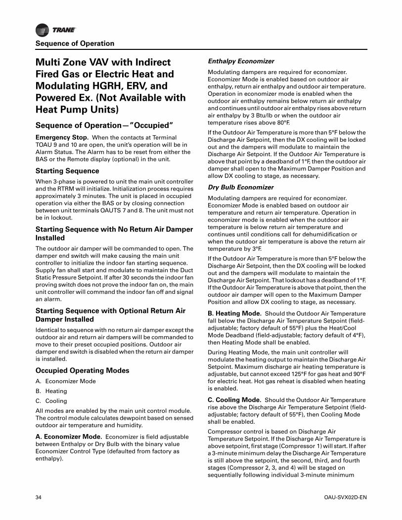
Sequence of Operation
Multi Zone VAV with Indirect
Fired Gas or Electric Heat and
Modulating HGRH, ERV, and
Powered Ex. (Not Available with
Heat Pump Units)
Sequence of Operation—”Occupied”
Emergency Stop. When the contacts at Terminal TOAU 9 and 10 are open, the unit’s operation will be in Alarm Status. The Alarm has to be reset from either the BAS or the Remote display (optional) in the unit.
Starting Sequence
When 3-phase is powered to unit the main unit controller and the RTRM will initialize. Initialization process requires approximately 3 minutes. The unit is placed in occupied operation via either the BAS or by closing connection between unit terminals OAUTS 7 and 8. The unit must not be in lockout.
Starting Sequence with No Return Air Damper
Installed
The outdoor air damper will be commanded to open. The damper end switch will make causing the main unit controller to initialize the indoor fan starting sequence. Supply fan shall start and modulate to maintain the Duct Static Pressure Setpoint. If after 30 seconds the indoor fan proving switch does not prove the indoor fan on, the main unit controller will command the indoor fan off and signal an alarm.
Starting Sequence with Optional Return Air
Damper Installed
Identical to sequence with no return air damper except the outdoor air and return air dampers will be commanded to move to their preset occupied positions. Outdoor air damper end switch is disabled when the return air damper is installed.
Occupied Operating Modes
A. Economizer Mode
B. Heating
C. Cooling
All modes are enabled by the main unit control module. The control module calculates dewpoint based on sensed outdoor air temperature and humidity.
A. Economizer Mode. Economizer is field adjustable between Enthalpy or Dry Bulb with the binary value Economizer Control Type (defaulted from factory as enthalpy).
Enthalpy Economizer
Modulating dampers are required for economizer. Economizer Mode is enabled based on outdoor air enthalpy, return air enthalpy and outdoor air temperature. Operation in economizer mode is enabled when the outdoor air enthalpy remains below return air enthalpy and continues until outdoor air enthalpy rises above return air enthalpy by 3 Btu/lb or when the outdoor air temperature rises above 80°F.
If the Outdoor Air Temperature is more than 5°F below the Discharge Air Setpoint, then the DX cooling will be locked out and the dampers will modulate to maintain the Discharge Air Setpoint. If the Outdoor Air Temperature is above that point by a deadband of 1°F, then the outdoor air damper shall open to the Maximum Damper Position and allow DX cooling to stage, as necessary.
Dry Bulb Economizer
Modulating dampers are required for economizer. Economizer Mode is enabled based on outdoor air temperature and return air temperature. Operation in economizer mode is enabled when the outdoor air temperature is below return air temperature and continues until conditions call for dehumidification or when the outdoor air temperature is above the return air temperature by 3°F.
If the Outdoor Air Temperature is more than 5°F below the Discharge Air Setpoint, then the DX cooling will be locked out and the dampers will modulate to maintain the Discharge Air Setpoint. That lockout has a deadband of 1°F. If the Outdoor Air Temperature is above that point, then the outdoor air damper will open to the Maximum Damper Position and allow DX cooling to stage, as necessary.
B. Heating Mode. Should the Outdoor Air Temperature fall below the Discharge Air Temperature Setpoint (field-adjustable; factory default of 55°F) plus the Heat/Cool Mode Deadband (field-adjustable; factory default of 4°F), then Heating Mode shall be enabled.
During Heating Mode, the main unit controller will modulate the heating output to maintain the Discharge Air Setpoint. Maximum discharge air heating temperature is adjustable, but cannot exceed 125°F for gas heat and 90°F for electric heat. Hot gas reheat is disabled when heating is enabled.
C. Cooling Mode. Should the Outdoor Air Temperature rise above the Discharge Air Temperature Setpoint (field-adjustable; factory default of 55°F), then Cooling Mode shall be enabled.
Compressor control is based on Discharge Air Temperature Setpoint. If the Discharge Air Temperature is above setpoint, first stage (Compressor 1) will start. If after a 3-minute minimum delay the Discharge Air Temperature is still above the setpoint, the second, third, and fourth stages (Compressor 2, 3, and 4) will be staged on sequentially following individual 3-minute minimum
34 OAU-SVX02D-EN

Sequence of Operation
delays between each call. Optional hot gas reheat will be used to temper the discharge air, if necessary.
Optional Features
Exhaust Fan Operation
Exhaust with Isolation Dampers
When the indoor fan operation has been proven and the unit is in occupied, there will be a call for the exhaust. When there is a call for the exhaust, the isolation dampers will be powered and the powered exhaust will be enabled once the end switch on the exhaust actuators are proven. If the unit is equipped with modulating dampers, the exhaust fan speed will modulate to maintain the Return Duct Pressure Setpoint (factory defaulted to 1 in. wc). If modulating dampers are not equipped, the exhaust will maintain a constant volume of airflow.
During Unoccupied, the powered exhaust will be shut off.
Exhaust with Gravity Dampers
When the indoor fan operation has been proven and the unit is in occupied, there will be a call for the exhaust. If the unit is equipped with modulating dampers, the exhaust fan speed will modulate to maintain the Return Duct Pressure Setpoint (factory defaulted to 1 in. wc). If modulating dampers are not equipped, the exhaust will maintain a constant volume of airflow.
During Unoccupied, the powered exhaust will be shut off.
Energy Wheel Operation
The ERV is interlocked with indoor fan and exhaust fan operation in occupied heating, dehumidification or cooling modes. When operating in Economizer Mode or Ventilation Mode the ERV is disabled and the ERV bypass dampers will open, powered exhaust remains on. If Economizer Mode has been enabled for 10 minutes, the ERV will be enabled for one minute. This cycle will repeat every 10 minutes. During Unoccupied, both the ERV and the powered exhaust will be shut off.
During ERV operation, if the Exhaust Temperature across the ERV drops below 25°F, the outdoor air bypass damper will start to slowly modulate open. If after the bypass dampers modulate to 100 percent open and the exhaust temp across the ERV drops below 15°F (2°F deadband) for 5 minutes, the unit controller will command the ERV off.
Optional Demand Control CO2 Ventilation
With CO2 sensor (field-supplied and -installed) and modulating damper option selected with the unit, the UC600 will look at the CO2 sensor value and compare it to the CO2 Setpoint. If the CO2 level in the space is higher than the setpoint, the UC600 will modulate the outdoor air damper open (PID loop in the controller is configurable) until the CO2 levels in the space are within the setpoint value. The UC600 will then close the OA damper (or minimum position based on the value in the PID loop) and wait for the space CO2 level to change again.
Optional Outdoor Airflow Monitoring
With Outdoor Airflow Monitoring sensor and modulating damper option selected with the unit, the UC600 will look at the Outdoor Airflow sensor value and compare it to the Outdoor Airflow Setpoint. If the outdoor airflow is lower than the setpoint, the UC600 will modulate the outdoor air damper open (PID loop in the controller is configurable) until the airflow levels reach the setpoint value or until the damper is at the Maximum Damper Position. The UC600 will continue to monitor the airflow and adjust damper position to match the outdoor airflow to the setpoint.
Optional Head Pressure Control
The Trane Horizon™ OAU head pressure variable speed control option (if selected) allows mechanical cooling for ambient conditions as low as 0°F. A temperature sensor on the header of the condenser coil will measure the saturated liquid temperature. Variable frequency drives will adjust the speed of two condenser fans as needed to maintain head pressure control.
Optional Secondary Pre-Heat
If an on/off pre-heater is installed, the heater will be enabled when the Outdoor Air Temperature is below a field selectable setpoint defaulted at 0°F.
If a modulating pre-heater is installed, the heater will be enabled when the primary heat is at 100 percent capacity but is unable to maintain setpoint. Once the pre-heater is enabled, the primary heat will remain at full capacity and the pre-heat will modulate to maintain Discharge Air Setpoint. Pre-heat will be disabled if the heater is at 0 percent and the space is over setpoint for an extended period of time.
Sequence of Operation—”Unoccupied”
Emergency Stop. When the contacts at Terminal OAUTS 9 and 10 are open, the unit’s operation will be in Alarm Status. Unit will begin normal operation upon closure of OAUTS 9 and 10.
Starting Sequence
Indoor fan proving sequence is identical to occupied operation.
Starting Sequence with Optional Return Air
Damper Installed
The outdoor air damper will be commanded to close and the return air damper will open. Outdoor air damper end switch is disabled when the return air damper is installed.
Starting Sequence with No Return Air Damper
Installed
Identical to occupied sequence no return air damper installed.
OAU-SVX02D-EN 35

Sequence of Operation
Operating Modes
A. Cooling
B. Heating
A. Unoccupied Cooling Mode. In order for unoccupied cooling to be enabled, a true value must be written to UNOCC Cooling Mode. Supply fan shall start and modulate to maintain the Duct Static Pressure Setpoint, the exhaust fan and energy wheel shall remain off, and the outside air damper shall remain closed. The unit shall stage the compressors to maintain the Discharge Air Temperature Setpoint. Unoccupied Cooling Mode will continue until a false value is written to the UNOCC Cooling Mode.
B. Unoccupied Heating Mode. In order for unoccupied heating to be enabled, a true value must be written to UNOCC Heating Mode. Supply fan shall start and modulate to maintain the Duct Static Pressure Setpoint, the exhaust fan and energy wheel shall remain off, and the outside air damper shall remain closed. The unit shall stage the heat to maintain the Discharge Air Temperature Setpoint. Unoccupied Heating Mode will continue until a false value is written to the UNOCC Heating Mode.
36 OAU-SVX02D-EN

Installation
Ductwork
Elbows with turning vanes or splitters are recommended to minimize air noise due to turbulence and to reduce static pressure.
When attaching the ductwork to the unit, provide a water- tight flexible connector at the unit to prevent operating sounds from transmitting through the ductwork.
All outdoor ductwork between the unit and the structure should be weather proofed after installation is completed.
Note: For sound consideration, cut holes in the roof deck only for the ductwork penetrations. Do not cut out the roof deck within the entire curb perimeter. All duct work must be installed and connected to top of roof curb before the unit is set on curb.
If a Curb Accessory Kit is not used:
1. Be sure to use flexible duct connections at the unit.
2. Gaskets must be installed around the curb perimeter flange and the supply and return air opening flanges.
Note: For units will electric heat in the primary heating position, refer to Figure 15.
General Unit Requirements
The checklist listed below is a summary of the steps required to successfully install a commercial unit. This checklist is intended to acquaint the installing personnel with what is required in the installation process. It does not replace the detailed instructions called out in the applicable sections of this manual.
WARNING
Hazardous Service Procedures!
Failure to follow all precautions in this manual and on the tags, stickers, and labels could result in death or serious injury.Technicians, in order to protect themselves from potential electrical, mechanical, and chemical hazards, MUST follow precautions in this manual and on the tags, stickers, and labels, as well as the following instructions: Unless specified otherwise, disconnect all electrical power including remote disconnect and discharge all energy storing devices such as capacitors before servicing. Follow proper lockout/tagout procedures to ensure the power can not be inadvertently energized. When necessary to work with live electrical components, have a qualified licensed electrician or other individual who has been trained in handling live electrical components perform these tasks.
Figure 15.
Important: Bottom discharge units with open coil electric heater in primary heat location require discharge duct with 90° elbow. This is a MANDATORY installation requirement.
Check the unit for shipping damage and material shortage. File a freight claim and notify appropriate sales representative if damage or shortage is discovered.
Verify that the unit nameplate model, options, and voltage are correct.
Verify that the installation location of the unit will provide the required clearance for proper operation.
Assemble and install the roof curb (if applicable). Refer to the latest edition of the curb installers guide that ships with each curb kit. Check curb for level installation; if not level, shim as required.
Convert unit to horizontal discharge and/or horizontal return if necessary (Refer to “OAB and OAG IF Heater Air Inlet Hood and Flue Assembly Instructions,” p. 38).
Rigging unit (refer to “Unit Weight and Rigging,” p. 20).
Set the unit onto the curb; check for level.
Ensure unit-to-curb seal is tight and without buckles or cracks.
48" Minimum
Airflow
OAU-SVX02D-EN 37

Installation
OAB and OAG IF Heater Air Inlet Hood and Flue Assembly Instructions
Unit is shipped with the IF heater air inlet hood and flue cover stowed in the blower compartment.
Important: Assemble the inlet hood and flue cover to the heater door before attempting any unit startup.
1. Open the blower compartment and remove the flue cover, wind screen, and heater air inlet hood.
2. Open the control panel door and remove the heater door shown in Figure 19.
Install and connect proper condensate drain line to the evaporator condensate pan drain connection (see Figure 24, p. 40).
Assemble indirect fired heater air inlet hood and flue assembly (refer to “OAB and OAG IF Heater Air Inlet Hood and Flue Assembly Instructions,” p. 38.)
Figure 16. Flue cover
Figure 17. Wind screen
Figure 18. Heater air inlet hood
Figure 19.
Controlpaneldoor
Heaterdoor
38 OAU-SVX02D-EN

Installation
3. Attach the flue cover to the heater door using the provided stainless steel screws as shown in Figure 20.
4. Attach the heater air inlet hood to the heater door using quantity (6) of the provided painted head screws as shown in Figure 21.
5. Attach the wind screen to the inside of the heater door using quantity (6) of the provided painted head screws as shown in Figure 22.
6. Install the heater door on the unit, as shown in Figure 23, p. 39, ensuring that the heater flue extends through the flue opening in the door.
Figure 20.
Figure 21.
Figure 22.
Figure 23.
OAU-SVX02D-EN 39

Installation
Main Electrical Power Requirements
Note: All field-installed wiring must comply with NEC and applicable local codes.
Condensate Drain Configuration
OAU units are selected based on dehumidification capability. As such, condensate can form at a high rate. Therefore, the OAU drain pan and condensate line are sized and designed accordingly. However, an often-overlooked element of proper condensate drainage is proper P-Trap and drain line sizing and installation. An incorrectly-designed and -installed P-Trap can restrict condensate flow or cause water in the condensate drain pan to “spit” or “geyser” which may cause condensate overflow. Carefully install and trap the drain pan to ensure adequate condensate removal under all conditions.
An evaporator condensate drain connection is provided on the unit. Refer to Figure 31, p. 43 for the drain location.
A condensate trap must be installed at the unit due to the drain connection being on the “negative pressure” side of the fan. Install the P-Trap using the guidelines in Figure 24.
Pitch drain lines connected to P-Trap at least 1/2 inch for every 10 feet of horizontal run to assure proper condensate flow. Do not allow the horizontal run to sag causing a possible double-trap condition which could result in condensate backup due to “air lock”.
Hot Water Control Valve Wiring
1. Mount the factory-provided water valve on the return line of the hot water coil.
2. Ensure the valve is set to normally open.
3. Run the 16 gauge black wire from TNS 2 to Input 1 of the actuator.
4. Run the 16 gauge red wire from TNS 2 to Input 2 of the actuator.
5. Run the 16 gauge yellow wire from AO1 from the UC600 to Input 3 of the actuator.
Note: The actuator valve will be open with a 0 percent call for heat.
Verify that the power supply complies with the unit nameplate specifications.
Inspect all control panel components; tighten any loose connections.
Connect properly sized and protected power supply wiring to a field-supplied/-installed disconnect switch and to the main power terminal block (HTB1) in the unit control panel.
Connect properly-sized earth ground.
Figure 24. Condensate trap installation
D = Pipe diameter; see Figure 31, p. 43 for correct pipe diameterH = Internal static pressure (in wg) +1 in.J = H x 0.5L = H + J +D
Notes:
1. Pitch drain at least 1/2 in. per 10 ft horizontal run. 2. Condensate drain pan will not drain properly if P-trap is not primed
and of adequate height to allow for cabinet operating negative pressure.
Figure 25. Hot water control valve wiring
PANEL ENCLOSURE
D" NPT FEMALE CONNECTOR
CLEANOUT PLUG
40 OAU-SVX02D-EN

Installation
Chilled Water Connection Size and Location
Filter Installation
The filter rack is accessible through the evaporator coil compartment door. Filter type, size, and quantity are determined by selected filter option and unit size.
Note: Do not operate the unit without filters.
Opening the Collapsed Exhaust Damper Hood
OAB Cabinet
1. To release the damper hood, remove the hex head sheet metal screws (one per side) shown in DETAIL A (see Figure 27) and marked by arrow (1).
2. Lift the hood upward and rotate the side panels outward while holding the top up.
3. As shown in DETAIL B (see Figure 28) and marked by arrow (2), secure the side panels to the top of the hood using (8) hex head sheet metal screws, provided with the unit, through the pre-punched holes in the top and side panels (four screws per side).
4. Repeat these steps for the remaining damper hood.
Figure 26. Outdoor air chilled water cooling pipe chase-
connections
Table 4. Chilled water pipe chase location (in.)
Unit A B C D E
OAB 61.25 12 10 3 3
OAG 79.75 12.5 10 3 4.125
Table 5. Chilled water connection size (MPT-in.)
Unit Size MPT-in.
OAB 3–9 tons 2
OAG 10–30 tons 2
Figure 27. OAB powered exhaust damper hood,
collapsed
OAU-SVX02D-EN 41

Installation
OAG Cabinet
1. To release damper hood, remove the hex head sheet metal screw shown in DETAIL A (see Figure 29) and marked by arrow (1).
2. Lift the hood upward and rotate the side panels outward while holding the top up.
3. As shown in DETAIL B (see Figure 30) and marked by arrow (2), secure the side panels to the top of the hood using (8) hex head sheet metal screws, provided with the unit, through the pre-punched holes in the top and side panels (four screws per side).
4. Repeat these steps for the remaining damper hood.
Figure 28. OAB powered exhaust damper hood, open Figure 29. OAG powered exhaust damper hood,
collapsed
42 OAU-SVX02D-EN

Installation
Field Installed Power Wiring
An overall dimensional layout for the standard field installed wiring entrance into the unit is illustrated in Figure 31, p. 43. To ensure that the unit’s supply power wiring is properly sized and installed, refer to the following guidelines.
Note: All field installed wiring must conform to NEC guidelines as well as State and Local codes.
Verify that the power supply available is compatible with the unit’s nameplate ratings. The available supply power must be within 10 percent of the rated voltage stamped on the nameplate. Use only copper conductors to connect the power supply to the unit.
Main Unit Power
Figure 30. OAG powered exhaust damper hood, open
WARNING
Proper Field Wiring and Grounding Required!
Failure to follow code could result in death or serious injury. All field wiring MUST be performed by qualified personnel. Improperly installed and grounded field wiring poses FIRE and ELECTROCUTION hazards. To avoid these hazards, you MUST follow requirements for field wiring installation and grounding as described in NEC and your local/state electrical codes.
Figure 31. OAB and OAG utility connections
WARNING
Hazardous Voltage!
Failure to disconnect power before servicing could result in death or serious injury. Disconnect all electric power, including remote disconnects before servicing. Follow proper lockout/tagout procedures to ensure the power can not be inadvertently energized.
OAB utility connections
GAS INLET1-1/4" MPT
CONDENSATEDRAIN
1/2" FPT
ELECTRICDISCONNECT
SWITCH
81.248
5.512
17.253
38.346
6.000
6.830
KCCInternational Inc.
OAG utility connections
OAU-SVX02D-EN 43

Installation
Standard Wiring
The electrical service must be protected from over current and short circuit conditions in accordance with NEC requirements. Protection devices must be sized according to the electrical data on the nameplate.
1. Location of the electrical service entrance is illustrated in Figure 31. Complete the unit’s power wiring connections onto either; the main terminal block HTB1 inside the unit control panel, the factory mounted non-fused disconnect switch (UCD) or circuit breaker (UCB), or the electric heat non-fused disconnect switch. Refer to the customer connection diagram that shipped with the unit for specific termination points.
2. Provide proper grounding for the unit in accordance with local and national codes.
Use the following checklist in conjunction with the checklist in “General Unit Requirements,” p. 37 to ensure that the unit is properly installed and ready for operation.
Voltage Imbalance
Three phase electrical power to the unit must meet stringent requirements for the unit to operate properly. Measure each leg (phase-to-phase) of the power supply. Each reading must fall within the utilization range stamped on the unit nameplate. If any of the readings do not fall within the proper tolerances, notify the power company to correct this situation before operating the unit.
Excessive three phase voltage imbalance between phases will cause motors to overheat and eventually fail. The maximum allowable voltage imbalance is 2.0 percent. Measure and record the voltage between phases 1, 2, and 3 and calculate the amount of imbalance as follows:
V1, V2, V3 = Line Voltage Readings
VD = Line Voltage reading that deviates the farthest from the average voltage.
Example: If the voltage readings of the supply power measured 221, 230, and 227, the average volts would be:
VD (reading farthest from average) = 221
The percentage of Imbalance equals:
NOTICE:
Use Copper Conductors Only!
Failure to use copper conductors could result in equipment damage as unit terminals are not designed to accept other types of conductors.
WARNING
Proper Field Wiring and Grounding Required!
Failure to follow code could result in death or serious injury. All field wiring MUST be performed by qualified personnel. Improperly installed and grounded field wiring poses FIRE and ELECTROCUTION hazards. To avoid these hazards, you MUST follow requirements for field wiring installation and grounding as described in NEC and your local/state electrical codes.
Verify that the correct size and number of filters are in place.
Inspect the interior of the unit for tools and debris and install all panels in preparation for starting the unit.
Check all electrical connections for tightness and “point of termination” accuracy.
Verify condenser airflow is unobstructed.
Verify that the condenser and indoor fans turn freely without rubbing and are properly tightened on the shafts.
Check motor mounting bolts and inlet cone for tightness. Free spin wheel by hand to check for proper alignment of motor, wheel, and inlet cone. Record motor nameplate amps at unit-rated voltage.
Check proper indoor fan wheel rotation. Wheel housing will be marked to indicate direction of proper rotation.
With access doors closed and secured, operate blower at 100 percent speed. Check amps to confirm operation within motor amp capacity.
WARNING
Live Electrical Components!
Failure to follow all electrical safety precautions when exposed to live electrical components could result in death or serious injury. When necessary to work with live electrical components, have a qualified licensed electrician or other individual who has been properly trained in handling live electrical components perform these tasks.
% Voltage Imbalance = 100 X AV - VD
where;AV
AV (Average Voltage) =Volt 1 + Volt 2 + Volt 3
3
221 + 230 + 227= 226 Avg.
3
100 X226 - 221
= 2.2%226
44 OAU-SVX02D-EN

Installation
The 2.2 percent imbalance in this example exceeds the maximum allowable imbalance of 2.0 percent. This much imbalance between phases can equal as much as a 20 percent current imbalance with a resulting increase in motor winding temperatures that will decrease motor life. If the voltage imbalance is over 2.0 percent, notify the proper agencies to correct the voltage problem before operating this equipment.
Electrical Phasing (Three-Phase Motors)
The compressor motor(s) and the supply fan motor are internally connected for the proper rotation when the incoming power supply is phased as A to L1, B to L2, and C to L3.
Proper electrical supply phasing can be quickly determined and corrected before starting the unit by using an instrument such as an Associated Research Model 45 Phase Sequence Indicator and following these steps:
Compressor Crankcase Heaters
To prevent injury or death from electrocution, it is the responsibility of the technician to recognize this hazard and use extreme care when performing service procedures with the electrical power energized.
Each compressor shall be equipped with a crankcase heater. The proper operation of the crankcase heater is important to maintain an elevated compressor oil temperature during the “Off” cycle to reduce oil foaming during compressor starts. Oil foaming occurs when refrigerant condenses in the compressor and mixes with the oil. In lower ambient conditions, refrigerant migration to the compressor could increase.
When the compressor starts, the sudden reduction in crankcase pressure causes the liquid refrigerant to boil rapidly causing the oil to foam. This condition could damage compressor bearings due to reduced lubrication and could cause compressor mechanical failures.
Before initial start up, or if main power has been off for an extended period of time, compressor crankcase heater(s) should be operated for a minimum of 8 hours prior to compressor operation. With main power OFF, remove jumper between OAUTS terminals 9 and 10 (E-Stop). Turn main power to energize crankcase heater(s). At end of warm up period turn main power off, install 9-10 jumper, turn main power on, and resume normal operation.
Following crankcase heater warm-up, turn main power disconnect off, and install jumper on E-Stop terminals 9 and 10.
Turn Main disconnect “On”.
Main Unit Display and ReliaTel Controls
When first powered “On”, the controls perform self-diagnostic initialization to check that all internal controls are functional. The Status LED located on the Main Unit Display and the Liteport LED located on the RTRM module is turned “On” within one second of power-up if internal operation is okay.
WARNING
Live Electrical Components!
Failure to follow all electrical safety precautions when exposed to live electrical components could result in death or serious injury. When necessary to work with live electrical components, have a qualified licensed electrician or other individual who has been properly trained in handling live electrical components perform these tasks.
Turn off the main source feeding power to the unit field-supplied or factory-installed main disconnect device (switch or circuit breaker).
Close the unit disconnect device cover, leaving disconnect switch in the off position, and turn main source power on.
Observe the ABC and CBA phase indicator lights on the face of the sequencer. The ABC indicator light will glow if the phase is ABC. If the CBA indicator light glows, turn main source power off and then open the unit main disconnect device cover and reverse any two power wires.
Restore the main source power and recheck the phasing. If the phasing is correct, turn main source power off then open the unit main disconnect device cover, remove the phase sequence indicator, reinstall disconnect device cover and, leaving disconnect device in the off position, turn main power source to unit on.
WARNING
Live Electrical Components!
Failure to follow all electrical safety precautions when exposed to live electrical components could result in death or serious injury. When necessary to work with live electrical components, have a qualified licensed electrician or other individual who has been properly trained in handling live electrical components perform these tasks.
OAU-SVX02D-EN 45

Installation
Field-Installed Control Wiring
An overall layout of the various control options available with the required number of conductors for each control device is illustrated in Figure 32, p. 47.
Note: All field wiring must conform to NEC guidelines as well as state and local codes.
Control Power Transformer
The 24-volt control power transformers are to be used only with the accessories called out in this manual. Transformers rated greater than 50 VA are equipped with internal circuit breakers. If a circuit breaker trips, turn “Off” all power to the unit before attempting to reset it.
The transformers are located in the control panel. The circuit breaker is located on the left side of the transformers and can be reset by pressing in on the black reset button.
Controls Using 24 Vac
Before installing any connecting wiring, refer to Figure 31, p. 43 for the electrical access locations provided on the unit and Table 6 for AC conductor sizing guidelines, and:
1. Use copper conductors unless otherwise specified.
2. Ensure that the AC control wiring between the controls and the unit’s termination point does not exceed three (3) ohms/ conductor for the length of the run.
Note: Resistance in excess of 3 ohms per conductor may cause component failure due to insufficient AC voltage supply.
3. Be sure to check all loads and conductors for grounds, shorts, and mis-wiring.
4. Do not run the AC low-voltage wiring in the same conduit with the high-voltage power wiring.
Controls Using DC Analog Input/Output (Standard Low Voltage Multiconductor Wire)
Before installing any connecting wiring between the unit and components utilizing a DC analog input\output signal, refer to Figure 31, p. 43 for the electrical access locations provided on the unit.
1. Table 7 lists the conductor sizing guidelines that must be followed when interconnecting the DC binary output devices and the system components utilizing a DC analog input\output signal to the unit.
Note: Resistance in excess of 2.5 ohms per conductor can cause deviations in the accuracy of the controls.
2. Ensure that the wiring between controls and the unit’s termination point does not exceed 2.5 ohms/conductor for the length of the run.
3. Do not run the electrical wires transporting DC signals in or around conduit housing high voltage wires.
WARNING
Proper Field Wiring and Grounding Required!
Failure to follow code could result in death or serious injury. All field wiring MUST be performed by qualified personnel. Improperly installed and grounded field wiring poses FIRE and ELECTROCUTION hazards. To avoid these hazards, you MUST follow requirements for field wiring installation and grounding as described in NEC and your local/state electrical codes.
WARNING
Hazardous Voltage!
Failure to disconnect power before servicing could result in death or serious injury. Disconnect all electric power, including remote disconnects before servicing. Follow proper lockout/tagout procedures to ensure the power can not be inadvertently energized.
WARNING
Hazardous Voltage!
Failure to disconnect power before servicing could result in death or serious injury. Disconnect all electric power, including remote disconnects before servicing. Follow proper lockout/tagout procedures to ensure the power can not be inadvertently energized.
NOTICE:
Use Copper Conductors Only!
Failure to use copper conductors could result in equipment damage as unit terminals are not designed to accept other types of conductors.
Table 6. 24 Vac conductors
Distance from Unit to Control Recommended Wire Size
000–460 feet000–140 m
18 gauge0.75 mm2
461–732 feet104–223 m
16 gauge1 mm2
WARNING
Hazardous Voltage!
Failure to disconnect power before servicing could result in death or serious injury. Disconnect all electric power, including remote disconnects before servicing. Follow proper lockout/tagout procedures to ensure the power can not be inadvertently energized.
46 OAU-SVX02D-EN

Installation
DC Conductors
Factory-Provided Sensors
A discharge temperature sensor (VELSEN-0021) will be factory-provided for field installation in the supply duct. Refer to Figure 39, p. 69 for installation instructions.
If space control is selected, a combination space temperature/humidity sensor (BAYSENS036A) will be factory-provided for field installation in the space. Refer to Figure 40, p. 70 for installation instructions.
If multi-zone VAV control is selected, a static pressure sensor (VELCON-0350) will be factory-provided for field installation in the supply duct or space. Refer to Figure 42, p. 72 for installation instructions.
If modulating OA/RA dampers w/economizer and an exhaust fan are selected, a duct static pressure sensor (VELCON-0350) will be factory-provided for field installation in the return duct. Refer to Figure 42, p. 72 for installation instructions.
Table 7. Zone sensor module wiring
Distance from Unit to Control Recommended Wire Size
000–150 feet0–45.7 m
22 gauge0.33 mm2
151–240 feet46–73.1 m
20 gauge0.50 mm2
241–385 feet73.5–117.3 m
18 gauge0.75 mm2
386–610 feet117.7–185.9 m
16 gauge1.3 mm2
611–970 feet186.2–295.7 m
14 gauge2.0 mm2
Figure 32. OAUTS Connection B
OAU-SVX02D-EN 47

48 OAU-SVX02D-EN
Pre-Start Check List
Task Initial Date
1. Voltage is present and landed at equipment.
2. Gas piping is complete and landed at each component. Inlet gas pressure to be between 7 in. wg and 14 in. wg.
3. Field installed sensors installed. Refer to “Factory-Provided Sensors,” p. 47 for list of sensors that may be required.
4. Control wiring installed and landed.
5. Accessories installed.
6. Ductwork installed (all runs in place, final tie in complete).
7. Drain lines installed and properly terminated.
8. Startup appointment with Horizon certified Trane service technician set and confirmed.
Notes:
• Check list must be completed and returned to Trane before startup is scheduled.
• Startup must be performed by a Horizon-certified Trane technician with Tracer™ TU program.
• Contractor to furnish access to equipment (ladder, lift, or roof access).

System Configuration and Pre-Start
The following procedure must be completed prior to performing the startup procedure in “Startup,” p. 52. This section describes procedures to navigate the various displays on the Unit Display and configure the Outdoor Air Unit Main Unit Display system setpoints and operating parameters.
Important: This section is intended to provide guidelines for navigation through the
remote operator display screens. For additional control system information, refer to Integration Guide: Tracer™ UC600 Programmable Controller for Packaged Outdoor Air Unit (BAS-SVP18*-EN). The unit is configured at the factory with the default settings as described in “Sequence of Operation,” p. 20
OAU-SVX02D-EN 49

System Configuration and Pre-Start
Table 8. Menu descriptions
Screen Menu Point List Min/Inactive Default Max/ActiveBAS Point?
AlarmsActive Alarms List of all active alarmsAll Alarms List of all previous alarms
Reports (continued on next page)
Custom Graphics *NOT USED*
System Status
Program Control Discharge Air Control Space Control Space Control YHeat Cool Mode Active Heat — Cool NOccupancy Status Occupied|Unoccupied|Occupied Bypass|Occupied Standby|Unknown YCompressor 1 Command Off — On NDigital Scroll Command 0% — 100% NDehumidification Command Disabled Enabled NDischarge Air Temperature Local Analog InputEconomizer Mode Disabled Enabled NEvap Leaving Temp Local Analog InputHeat Capacity 0% — 100% NHeating Output Command 0% — 100% NHeat 1 Command Off — On NHeat 2 Command Off — On NInducer Command Off — On NGas Valve Status Binary InputHGRH Command 0% — 100% NOA Damper End Switch Binary InputOutdoor Air Damper Command Closed — Open NOAD Position Local Binary InputOutdoor Air Relative Humidity Local Analog InputOutdoor Air Temperature Local Analog InputSpace Dewpoint Active Analog InputSpace Temperature Local Analog InputSupply Fan Start Stop Command Off — Off NFilter Status Clean — Dirty NSystem Lockout Normal Normal Lockout NUNOCC Cooling Mode Off — On NUNOCC Dehumid Mode Off — On NUNOCC Heating Mode Off — On NERV Command Disable — Enable NERV Leaving Air Temperature Local Analog InputPEVFD Command 0% 80% 100% YDischarge Airflow Local Analog InputERV Leaving Air Humidity Local Analog Input
50 OAU-SVX02D-EN
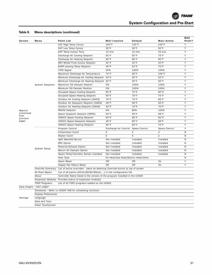
System Configuration and Pre-Start
Reports (continued from previous page)
System Setpoints
DAT High Temp Cutout 100°F 125°F 150°F YDAT Low Temp Cutout 35°F 35°F 50°F YDAT Temp Cutout Time 10 min. 10 min. 25 min. YDischarge Air Cooling Setpoint 55°F 55°F 75°F YDischarge Air Heating Setpoint 65°F 85°F 90°F YERV Wheel Frost Cutout Setpoint 32°F 34°F 40°F YEVAP Leaving Temp Setpoint 45°F 53°F 70°F YIVFD Signal 50% 100% 100% YMaximum Discharge Air Temperature 70°F 90°F 100°F YMinimum Discharge Air Cooling Setpoint 40°F 50°F 65°F YMinimum Discharge Air Heating Setpoint 50°F 55°F 60°F YMaximum OA Damper Position 0% 100% 100% YMinimum OA Damper Position 0% 100% 100% YOccupied Space Cooling Setpoint 65°F 74°F 90°F YOccupied Space Heating Setpoint 60°F 70°F 75°F YOutdoor Air Cooling Setpoint (OACS) 70°F 75°F 85°F YOutdoor Air Dewpoint Setpoint (OADS) 49°F 58°F 65°F YOutdoor Air Heating Setpoint (OAHS) 40°F 70°F 70°F YPEVFD Setpoint 0% 80% 100% YSpace Dewpoint Setpoint (SPDS) 50°F 59°F 68°F YUNOCC Space Cooling Setpoint 60°F 80°F 90°F YUNOCC Space Dewpoint Setpoint 49°F 65°F 68°F YUNOCC Space Heating Setpoint 50°F 60°F 70°F Y
System Setup
Program Control Discharge Air Control Space Control Space Control YCompressor Count 0 0 4 NHeater Count 0 0 2 NSplit Manifold Burner Not Installed Installed Installed NERV Option Not Installed Installed Installed NPowered Exhaust Option Not Installed Installed Installed NReturn Air Damper Option Not Installed Installed Installed NSpace Temp/Humidity Sensor Installed Not Installed Installed Installed NHeat Type No Heat|Gas Heat|Electric Heat|Other NAlarm Reset Off Off On YSupply Fan Failure Reset Off Off On Y
Override Summary List of active overrides - same as selecting Override button at top of screenAll Point Report List of all points (AO/AI/BO/BI/MS/etc …) in the configuration fileAbout Controller Name listed is the version of the program installed in the UC600Expansion Modules Provides status of expansion modulesTGP2 Programs List of all TGP2 programs loaded on the UC600
Data Graphs *NOT USED*
Settings
Schedules - Refer to UC600 IOM for scheduling functionsDisplay PreferencesLanguageDate and TimeClean Touchscreen
Table 8. Menu descriptions (continued)
Screen Menu Point List Min/Inactive Default Max/ActiveBAS Point?
OAU-SVX02D-EN 51

Startup
Indirect Gas-Fired Heating
Startup
Notes:
1. This furnace module does not have a pilot. It is equipped with a direct spark ignition device that automatically lights the gas burner. DO NOT try to light burners by hand.
2. BEFORE OPERATING, leak test all gas piping up to heater gas valve. Smell around the unit area for gas. If gas is smelled, do NOT attempt to place heater in operation until source of gas leak is identified and corrected.
3. Use only hand force to operate the gas control lever to the “ON” position. NEVER use tools. If lever does not operate by hand, replace gas valve prior to staring the unit. Forcing or attempting to repair the gas valve may result in fire or explosion.
4. Do not attempt to operate unit, if there is indication that any part or control has been under water. Any control or component that has been under water must be replaced prior to trying to start the unit.
Refer to “Sequence of Operation,” p. 20 for additional information.
Tools Required
• Voltage Meter (μA)• Amp Meter• Gas Manometer (2)• Temperature Probe• Small Refrigeration Screwdriver• 5/16-in. Nut Driver• 3/16-in. Allen Wrench• 3/32-in. Allen Wrench• 1/8-in. NPT barbed pressure taps (3)• 1/2-in. Open End Wrench
Startup Procedure
1. Check Inlet Gas Pressure
Check to insure the gas pressure supplied to the unit is within the pressure requirement listed on the nameplate. DO NOT expose gas controls to pressures above 1/2 psi (14 in. wc). The gas supply line should be installed with an external manual shutoff and pressure tap.
2. Verify Indoor Fan Failure Switch Operation
Indoor Fan Failure Switch (IFFS) is located in the unit electrical control compartment above the heater. Indoor fan failure switch will fail if not proven within 30 seconds of call for indoor fan—ON.
All unit air filters must be clean before proceeding to properly complete this verification.
Important: If the unit air filters are not clean, unit performance could be affected. Remove and clean or replace air filters as required prior to proceeding with the burner pressure testing.
In the event that the pressure switch fails to operate, check the pick-up tubes to be certain that the tubes are not obstructed and confirm that the tube connections to IFFS are tight and secure.
WARNING
Hazardous Service Procedures!
Failure to follow all precautions in this manual and on the tags, stickers, and labels could result in death or serious injury.
• Technicians, in order to protect themselves from
potential electrical, mechanical, and chemical
hazards, MUST follow precautions in this manual and
on the tags, stickers, and labels, as well as the
following instructions: Unless specified otherwise,
disconnect all electrical power including remote
disconnect and discharge all energy storing devices
such as capacitors before servicing. Follow proper
lockout/tagout procedures to ensure the power can
not be inadvertently energized. When necessary to
work with live electrical components, have a
qualified licensed electrician or other individual who
has been trained in handling live electrical
components perform these tasks.
• Do not attempt the following procedures until all
electrical and gas connections to the unit have been
completed and the outdoor air damper and
evaporator fan operation have been verified and are
operating correctly.
WARNING
Hazard of Explosion!
Failure to follow proper safe leak test procedures could result in death or serious injury or equipment or property-only-damage. NEVER use an open flame to detect gas leaks. You MUST use a leak test solution for leak testing.
52 OAU-SVX02D-EN

Startup
3. Confirm Gas Flow at Unit
Open door to unit vestibule housing the gas heater. Move gas control lever to “OFF” position. Remove 1/8-in. pressure taps (see Figure 34, p. 55) from both modulating and on-off sections of the split heater manifold. Install a barbed fitting in both 1/8-in. tapped holes for connection to individual gas manometers.
Note: There is a third 1/8-in. gas pressure tap located in the pipe connecting the main valve/regulator and modulating valve. Maximum pressure into modulating valve is 5-in. The On-Off gas valve includes a regulator adjustment device that is located on the top of the valve. Use this device to regulate valve output to modulating valve as required.
Wait 5 minutes for any gas to clear. If you smell gas, see Step 2 and correct leak. If you don’t smell gas or have corrected any leaks, go to Step 4.
4. Burner Starting Sequence and Burner Ignition
Figure 34, p. 55 illustrates indirect gas-fired furnace components.
5. Main Gas Supply
Turn manual gas cock “ON”.
6. Split Manifold High Fire and Burner Test
Open all manual gas valves. Turn power on at unit’s main disconnect switch. Open gas supply manual shut-off valve. Using unit display (or computer with Trane Tracer TU), proceed to System Status Display and Override all Compressor stages OFF, Disable Dehumidification, Disable Economizer Mode, Disable ERV. If two heaters are installed, test heating with split manifold first by overriding burner 2 OFF. Override heating Output Command to 100.0 percent if one heater is installed and to 49 percent if two heaters are installed. Override Heat Cool Mode Active to Heat. This will enable call for heat to split manifold heater. Depending on outdoor air temperature, at time of startup, heater high limit temperature may be exceeded causing limit switch to trip. Limit switch is auto-reset. Limit switch must be jumpered out of the circuit if OA temperature dictates.
With limit switch closed, the draft inducer will run on high speed for 10 seconds for proof of high and low airflow switch closure, then begin a 30-second pre-purge period. At the end of the pre-purge the direct
spark will be energized and On-Off gas valve will open for a 5-second ignition trial. Following successful ignition, the inducer remains on high for 10-second flame stabilization, followed by 30-second warm up. Should the flame go out or the burner fail to light, an ignition retry will initiate following a 15-second inter-purge period.
Following successful ignition, manifold pressure should be 1.2 in. wc during the warm-up period. The manifold pressure will rise to 3.5 in. wc at 100 percent firing rate. Following these sequences to check low fire gas pressure for modulating section, reduce Heating Output Command to 0 percent. Inducer speed will reduce to low speed. Correct gas pressure for modulating manifold section of heater at 0 percent output signal or low fire will be 0.17 in. For modulating sections, the outlet gas pressure from main/regulator valve into the modulating valve is 5-in. wc.
Main On-Off valves in 1/2-in. gas line require 3/32-in. Allen wrench to adjust outlet gas pressure. Valves in 3/4-in. gas line require flat blade screwdriver to adjust outlet gas pressure. Following these sequences, inducer speed will reduce to low speed and will now be speed-controlled by the heater controller based on gas input to burners.
With heating command at 100 percent and with a single split manifold heater installed, the On-Off section of the heater will require the modulating section to prove ON before the On-Off section will enable. Inducer speed high at all times the On-Off section is in ignition sequence or firing. On-Off section sequence includes a 1-second ignition pre-purge followed by 4-second ignition trial. Ignition or flame failure will be followed by 30-second inter-purge for two ignition retry then 5-minute lockout period if both retry attempts fail. Correct manifold gas pressure for On-Off heater section is 3.5 in. wc.
For units including an additional separate On-Off heater, set heat command output to 49 percent to run modulating heater startup. When complete with modulating heater startup, increase heat output command to 100 percent to start up the second heater.
Failure to Ignite
• On the initial startup, or after unit has been off long periods of time, the first ignition trial may be unsuccessful due to need to purge air from manifold at startup.
• If ignition does not occur on the first trial, the gas and spark are shut-off by the ignition control and the control enters an inter-purge period of 15 seconds, during which the draft inducer continues to run.
• At the end of the inter-purge period, another trial for ignition will be initiated.
• Control will initiate up to three ignition trials on a call for heat before lockout of control occurs.
WARNING
Hazardous Voltage and Gas!
Failure to turn off gas or disconnect power before servicing could result in an explosion or electrocution which could result in death or serious injury. Turn off the gas supply and disconnect all electric power, including remote disconnects, before servicing the unit. Follow proper lockout/tagout procedures to ensure the power can not be inadvertently energized.
OAU-SVX02D-EN 53

Startup
• Control can be brought out of lockout by cycling call for heat at the Main Unit Display.
Prior to completing the startup, check the appearance of the main burner flame. Refer to Figure 33 for flame characteristics of properly adjusted natural gas systems.
Main burner flame
• The burner flame should be predominately blue in color and well defined and centered at the tube entry as shown in Figure 33 above. Distorted flame or yellow tipping of natural gas flame, or a long yellow flame on propane, may be caused by lint and dirt accumulation inside burner or at burner ports, at air inlet between burner and manifold pipe, or debris in the main burner orifice. Soft brush or vacuum clean affected areas.
• Poorly defined, substantially yellow flames, or flames that appear lazy, indicate poor air supply to burners or excessive burner input. Verify gas supply type and manifold pressure with rating plate.
• Poor air supply can be caused by obstructions or blockage in heat exchanger tubes or vent discharge pipe. Inspect and clean as necessary to eliminate blockage. Vacuum any dirt or loose debris. Clean heat exchanger tubes with stiff brush. Poor flame characteristics can also be caused by flue gas recirculation into combustion air supply. If surrounding buildings or prevailing winds cause recirculation, a flue extension may be required to prevent recirculation. Contact manufacturer prior to making any flue adjustments.
• Reduced air delivery can also be the result of inducer fan blade slippage, dirt accumulation in the fan blade or low voltage to draft inducer motor. Inspect draft fan assembly and be sure fan blade is secure to motor shaft. Check line voltage to heater.
7. Flame Sensor Current Check
Flame current is the current which passes through the flame from the sensor to ground. A flame signal of 0.5 to 1.0 microamp (μA) is marginal. For dependable operation, a flame signal of greater than 1.0 μA is required. To measure flame current, connect a meter capable of reading micro-amp current so the flame signal will be read thru the meter’s COM and μA connections. The meter should read greater than 1.0 μA.
Note: If the meter reads below “0” on scale, meter leads are reversed; disconnect power and reconnect meter leads for proper polarity.
Figure 33. Flame characteristics of properly-adjusted
natural gas systems
Burner flame at startup: 1.2 in. wc manifold pressure draft inducer—high speed
Burner flame at high fire: 3.5 in. wc manifold pressure draft inducer—high speed
NOTICE:
Meter Damage!
Measuring voltage with meter connect to a circuit could result in meter damage. Do NOT measure voltage with meter connected to a circuit.
54 OAU-SVX02D-EN

Startup
Safety Controls
Air Pressure Switch. An air pressure switch is provided as part of the control system to verify airflow through draft inducer by monitoring the difference in pressure between the draft inducer and the atmosphere. If sufficient negative pressure is not present, indicating lack of proper air movement through heat exchanger, the switch opens shutting off gas supply though the ignition control module. On units with two speed draft inducer operation, a dual air pressure switch is used, monitoring high and low speed pressures. The air pressure switches have fixed settings and are not adjustable.
Rollout Switch (Manual Reset). The furnace module is equipped with manual reset rollout switch(es) in the event of burner flame rollout. The switch will open on temperature rise and shut-off gas supply through the ignition control module. Flame rollout can be caused by insufficient airflow for the burner firing rate (high gas pressure), blockage of the vent system or in the heat exchanger. The furnace module should not be placed back in operation until the cause of rollout condition is identified and corrected. The rollout switch can be reset by pressing the button on top of the switch.
High Limit Switch. The furnace module is equipped with a fixed temperature high limit switch mounted on the vestibule panel that shuts off gas to the heater through the ignition control module in the event of reduced airflow over the heat exchanger tubes. Reduced airflow can be caused by indoor fan failure, dirty or blocked filters, or restriction of the air inlet or outlet to the unit. The high limit switch will automatically reset when the air temperature drops to approximately 30°F below the limit setpoint. Determine the cause of the reduced air flow and correct.
Figure 34. OAB/OAG Indirect gas-fired furnace components
INDUCER MOTOR
INLET PRESSURE TAP
IGNITION
ON/OFF GAS VALVE
ON/OFF GAS VALVE
MANIFOLD GAS
INLET PRESSURE = 7” W.C./14" W.C.
AIR-PROVING
PRESSURE TAP
SWITCH
MINIMUM/MAXIMUM
PRESSURE TAPMANIFOLD GAS
ROLLOUT SWITCH
CONTROLLERS
CONDENSATE DRAIN(TYP. 2)
INDUCER BLOWER
MODULATING VALVE
FLAMESENSOR
HIGH LIMIT SWITCH
ROLLOUTSWITCH
MODULATINGGAS VALVE
INLET PRESSURE = 7” W.C./14" W.C.
MINIMUM/MAXIMUM
OAU-SVX02D-EN 55
Maintenance
Make sure all personnel are standing clear of the unit before proceeding. The system components will start when the power is applied.
Monthly Maintenance
Before completing the following checks, turn the unit OFF and lock the main power disconnect switch open.
Filters
• Inspect the return air filters. Clean or replace them if necessary. Refer to the unit Service Facts for filter information.
Supply/Return Air Smoke Detector Maintenance
Airflow through the unit is affected by the amount of dirt and debris accumulated on the indoor coil and filters.
To insure that airflow through the unit is adequate for proper sampling by the return air smoke detector, complete adherence to the maintenance procedures, including recommended intervals between filter changes, and coil cleaning is required.
Periodic checks and maintenance procedures must be performed on the smoke detector to insure that it will function properly.
For detailed instructions concerning these checks and procedures, refer to the appropriate section(s) of the smoke detector Installation and Maintenance Instructions provided with the literature package for this unit.
Cooling Season
• Check the unit’s drain pans and condensate piping to ensure that there are no blockages.
• Inspect the evaporator and condenser coils for dirt, bent fins, etc. If the coils appear dirty, clean them according to the instructions described in “Condenser Coil Cleaning,” p. 56.
• Manually rotate the condenser fan(s) to ensure free movement and check motor bearings for wear. Verify that all of the fan mounting hardware is tight.
• Inspect the F/A-R/A damper hinges and pins to ensure that all moving parts are securely mounted. Keep the blades clean as necessary.
• Verify that all damper linkages move freely; lubricate with white grease, if necessary.
• Check supply fan motor bearings; repair or replace the motor as necessary.
• Check the fan shaft bearings for wear. Replace the bearings as necessary.
• Verify that all wire terminal connections are tight.
• Remove any corrosion present on the exterior surfaces of the unit and repaint these areas.
• Generally inspect the unit for unusual conditions (e.g., loose access panels, leaking piping connections, etc.).
• Make sure that all retaining screws are reinstalled in the unit access panels once these checks are complete.
• With the unit running, check and record the: ambient temperature; compressor suction and discharge pressures; superheat; Record this data on an “operator’s maintenance log” like the one shown in Table 9, p. 58. If the operating pressures indicate a refrigerant shortage, measure the system superheat.
Note: Do NOT release refrigerant to the atmosphere! If adding or removing refrigerant is required, the service technician must comply with all federal, state and local laws.
Heating Season
• Inspect the unit’s air filters. If necessary, clean or replace them.
• Check supply fan motor bearings; repair or replace the motor as necessary.
• Inspect both the main unit control panel and heat section control box for loose electrical components and terminal connections, as well as damaged wire insulation. Make any necessary repairs.
• Verify that the electric heat system operates properly.
Condenser Coil Cleaning
Regular coil maintenance, including annual cleaning, enhances the unit’s operating efficiency by minimizing: compressor head pressure and amperage draw; evaporator water carryover; fan brake horsepower, due to increase static pressure losses; airflow reduction.
At least once each year, or more often if the unit is located in a “dirty” environment, clean the condenser coils using the instructions outlined below. Be sure to follow these instructions as closely as possible to avoid damaging the coils.
WARNING
Hazardous Voltage!
Failure to disconnect power before servicing could result in death or serious injury. Disconnect all electric power, including remote disconnects before servicing. Follow proper lockout/tagout procedures to ensure the power can not be inadvertently energized.
56 OAU-SVX02D-EN

Maintenance
Microchannel (MCHE) Coils
Due to the soft material and thin walls of the MCHE coils, the traditional field maintenance method recommended for Round Tube Plate Fin (RTPF) coils does not apply to microchannel coils.
Moreover, chemical cleaners are a risk factor to MCHE due to the material of the coil. The manufacturer does not recommend the use of chemical cleaners to clean microchannel coils. Using chemical cleaners could lead to warranty claims being further evaluated for validity and failure analysis.
The recommended cleaning method for microchannel condenser coils is pressurized water or air with a non-pinpoint nozzle and an ECU of at least 180 with pressure no greater than 600 psi. To minimize the risk of coil damage, approach the cleaning of the coil with the pressure washer aimed perpendicular to the face of the coil during cleaning. Optimum clearance between the sprayer nozzle and the microchannel coil is 1 in.–3 in.
Round Tube Plate Fin (RTPF) Coils
To clean refrigerant coils, use a soft brush and a sprayer (either a garden pump-up type or a high-pressure sprayer). A high-quality detergent is also required; suggested brands include “SPREX A.C.”, “OAKITE 161”, “OAKITE 166” and “COILOX”. If the detergent selected is strongly alkaline (pH value exceeds 8.5), add an inhibitor.
1. Remove enough panels from the unit to gain access to the coil.
2. Protect all electrical devices such as motors and controllers from any over spray.
3. Straighten any bent coil fins with a fin comb.
4. Mix the detergent with water according to the manufacturer’s instructions. If desired, heat the solution BUT DO NOT EXCEED 150ºF maximum to improve its cleansing capability.
5. Pour the cleaning solution into the sprayer. If a high-pressure sprayer is used:
a. do not allow sprayer pressure to exceed 600 psi.
b. the minimum nozzle spray angle is 15°.
c. maintain a minimum clearance of 6 in. between the sprayer nozzle and the coil.
d. spray the solution perpendicular (at 90°) to the coil face.
6. Spray the leaving-airflow side of the coil first; then spray the opposite side of the coil. Allow the cleaning solution to stand on the coil for five minutes.
7. Rinse both sides of the coil with cool, clean water.
8. Inspect both sides of the coil; if it still appears to be dirty, repeat Step 6 and Step 7.
9. Reinstall all of the components and panels removed in Step 1 and any protective covers installed in Step 2.
Note: For units equipped with hail guards follow reinstallation procedure listed below.
NOTICE:
Coil Damage!
Failure to follow instructions below could result in coil damage. DO NOT use any detergents with microchannel condenser coils. Use pressurized water or air ONLY, with pressure no greater than 600psi.
For additional information regarding the proper microchannel coil cleaning procedure, refer to service bulletin RT-SVB83*-EN.
WARNING
Hazardous Chemicals!
Failure to follow all safety instructions below could result in death or serious injury. Coil cleaning agents can be either acidic or highly alkaline and can burn severely if contact with skin occurs. Handle chemical carefully and avoid contact with skin. ALWAYS wear Personal Protective Equipment (PPE) including goggles or face shield, chemical resistant gloves, boots, apron or suit as required. For personal safety refer to the cleaning agent manufacturer’s Materials Safety Data Sheet and follow all recommended safe handling practices.
WARNING
Hazardous Pressures!
Failure to follow safety precautions below could result in coil bursting, which could result in death or serious injury. Coils contain refrigerant under pressure. When cleaning coils, maintain coil cleaning solution temperature under 150°F to avoid excessive pressure in the coil.
OAU-SVX02D-EN 57

Maintenance
Final Process
For future reference, you may find it helpful to record the unit data requested below in the blanks provided.
(1) Complete Unit Model Number:
_____________________________________________________
_____________________________________________________
_____________________________________________________
(2) Unit Serial Number:
_____________________________________________________
_____________________________________________________
_____________________________________________________
(3) Wiring Diagram Numbers (from unit control panel)
— schematic(s)
_____________________________________________________
_____________________________________________________
_____________________________________________________
_____________________________________________________
_____________________________________________________
— connection(s)
_____________________________________________________
_____________________________________________________
_____________________________________________________
Table 9. Sample maintenance log
Date
Current Ambient
Temp F/C
Refrigerant Circuit #1 Refrigerant Circuit #2
Compr. Oil Level
Suct. Press.
Psig/kPa
Disch. Press
Psig/kPa
Liquid Press
Psig/kPa Super-
heat F/C Sub-cool
F/C Compr.
Oil Level
Suct. Press.
Psig/kPa
Disch. Press
Psig/kPa
Liquid Press
Psig/kPa Super-
heat F/CSub-cool
F/C - ok- low
- ok- low
- ok- low
- ok- low
- ok- low
- ok- low
- ok- low
- ok- low
- ok - low
- ok - low
- ok- low
- ok- low
- ok- low
- ok- low
- ok- low
- ok- low
- ok- low
- ok- low
- ok- low
- ok- low
- ok- low
- ok- low
- ok- low
- ok- low
- ok- low
- ok- low
58 OAU-SVX02D-EN

Performance Data
Table 10. OABD General Data—Cooling 3–5 Tons High Efficiency
3 Tons 4 Tons 5 TonsOABD036A OABD048A OABD060A
Cooling PerformanceGross Cooling Capacity, Btu (kW) 41,462 (12.15) 55,709 (16.33) 66,870 (19.60)Nominal cfm (m3/h) 500–2000 (850–3398) 500–2000 (850–3398) 500–2000 (850–3398)
CompressorNumber 1 1 1Type Scroll Scroll Scroll
Outdoor CoilType High Performance High Performance High PerformanceTube Size—OD, in. (mm) 3/8 (9.5) 3/8 (9.5) 3/8 (9.5)Face Area, ft2 (m2) 11 (1.02) 11 (1.02) 11 (1.02)Rows 2 2 2FPI 14 14 14
Indoor CoilType Propeller Propeller PropellerTube Size—OD, in. (mm) 1/2 (12.7) 1/2 (12.7) 1/2 (12.7)Face Area, ft2 (m2) 4.17 (0.39) 4.17 (0.39) 4.17 (0.39)Rows 4 4 4FPI 12 12 12Refrigerant Control TXV TXV TXVDrain Connection Size, in. (mm) 3/4 (20) 3/4 (20) 3/4 (20)
Outdoor FanType Propeller Propeller PropellerNumber Used 1 1 1Diameter, in. (mm) 27 27 27Drive Type Direct Direct DirectNo. Speeds 1 1 1CFM (m3/h) 7,000 (11,893) 7,000 (11,893) 7,000 (11,893)Number Motors 1 1 1Motor HP (kW), per motor 1.0 (0.75) 1.0 (0.75) 1.0 (0.75)Motor RPM 1140 1140 1140
Indoor FanType Backward Curved Backward Curved Backward CurvedNumber Used 1 1 1Diameter Varies Varies VariesDrive Type Direct Drive Direct Drive Direct DriveNumber Motors 1 1 1Motor HP (kW), Standard–Oversized 2.68–4.0 (2–3) 2.68–4.0 (2–3) 2.68–4.0 (2–3)Motor RPM Varies Varies Varies
FiltersType Furnished Varies Varies VariesEvap Size, in. (Qty) 20 x 24 x 2 (2) 20 x 24 x 2 (2) 20 x 24 x 2 (2)Type Furnished MERV-8 MERV-8 MERV-8ERV Size, in. (Qty) 20 x 24 x 2 (4) 20 x 24 x 2 (4) 20 x 24 x 2 (4)
Refrigerant Charge, lb of R-410A See Nameplate See Nameplate See Nameplate
OAU-SVX02D-EN 59

Performance Data
Table 11. OABD General Data—Cooling 6–9 Tons High Efficiency
6 Tons 7 Tons 8 Tons 9 TonsOABD072A OABD084A OABD096A OABD108A
Cooling PerformanceGross Cooling Capacity, Btu (kW) 78,600 (23.04) 88,768 (26.02) 99,099 (29.04) 108,214 (31.71)Nominal cfm (m3/h) 625–3000 (1061–5097) 625–3000 (1061–5097) 625–3000 (1061–5097) 625–3000 (1061–5097)
CompressorNumber 1 1 1 1Type Scroll Scroll Scroll Scroll
Outdoor CoilType High Performance High Performance High Performance High PerformanceTube Size—OD, in. (mm) 3/8 (9.5) 3/8 (9.5) 3/8 (9.5) 3/8 (9.5)Face Area, ft2 (m2) 11 (1.02) 11 (1.02) 11 (1.02) 11 (1.02)Rows 2 2 2 2FPI 14 14 14 14
Indoor CoilType High Performance High Performance High Performance High PerformanceTube Size—OD, in. (mm) 3/8 (12.7) 1/2 (12.7) 1/2 (12.7) 1/2 (12.7)Face Area, ft2 (m2) 6.56 (167) 5.69 (145) 6.56 (167) 5.69 (145) 6.56 (167) 5.69 (145) 6.56 (167) 5.69 (145)Rows 4 6 4 6 4 6 4 6FPI 12 12 12 12Refrigerant Control TXV TXV TXV TXVDrain Connection Size, in. (mm) 3/4 (20) 3/4 (20) 3/4 (20) 3/4 (20)
Outdoor FanType Propeller Propeller Propeller PropellerNumber Used 1 1 1 1Diameter, in. (mm) 27 27 27 27Drive Type Direct Direct Direct DirectNo. Speeds 1 1 1 1CFM (m3/h) 7,000 (11,893) 7,000 (11,893) 7,000 (11,893) 7,000 (11,893)Number Motors 1 1 1 1Motor HP (kW), per motor 1.0 (0.75) 1.0 (0.75) 1.0 (0.75) 1.0 (0.75)Motor RPM 1140 1140 1140 1140
Indoor FanType Backward Curved Backward Curved Backward Curved Backward CurvedNumber Used 1 1 1 1Diameter Varies Varies Varies VariesDrive Type Direct Drive Direct Drive Direct Drive Direct DriveNumber Motors 1 1 1 1Motor HP (kW), Standard–Oversized 2.68–4.0 (2–3) 2.68–4.0 (2–3) 2.68–4.0 (2–3) 2.68–4.0 (2–3)Motor RPM Varies Varies Varies Varies
FiltersType Furnished Varies Varies Varies VariesEvap Size, in. (Qty) 20 x 24 x 2 (2) 20 x 24 x 2 (2) 20 x 24 x 2 (2) 20 x 24 x 2 (2)Type Furnished MERV-8 MERV-8 MERV-8 MERV-8ERV Size, in. (Qty) 20 x 24 x 2 (4) 20 x 24 x 2 (4) 20 x 24 x 2 (4) 20 x 24 x 2 (4)
Refrigerant Charge, lb of R-410A See Nameplate See Nameplate See Nameplate See Nameplate
60 OAU-SVX02D-EN

Performance Data
Table 12. OAGD General Data—Cooling 10–17 Tons High Efficiency
10 Tons 12 Tons 15 Tons 17 Tons OAGD120A OAGD144A OAGD180A OAGD210A
Cooling PerformanceGross Cooling Capacity, Btu (kW) 150,692 (44.16) 165,990 (48.65) 206,544 (60.53) 230,212 (67.47)
CFMNominal cfm (m3/h) 1250–2500 (2124–4248) 1500–3000 (2549–5097) 1875–3750 (3186–6371) 2125–4250 (3610–7221)
CompressorNumber 2 2 2 2Type Scroll Scroll Scroll Scroll
Outdoor CoilType High Performance High Performance High Performance High PerformanceTube Size—OD, in. (mm) 3/8 (9.5) 3/8 (9.5) 3/8 (9.5) 3/8 (9.5)Face Area, ft2 (m2) 25 (2.32) 25 (2.32) 25 (2.32) 25 (2.32)Rows 2 2 2 2FPI 14 14 14 14
Indoor CoilType High Performance High Performance High Performance High PerformanceTube Size—OD, in. (mm) 1/2 (12.7) 1/2 (12.7) 1/2 (12.7) 1/2 (12.7)Face Area, ft2 (m2) 10.0 (0.93) 10.0 (0.93) 10.0 (0.93) 12.0 (1.11)Rows 4 6 4 6 4 6 4 6FPI 12 12 12 12Refrigerant Control TXV TXV TXV TXVDrain Connection Size, in. (mm) 3/4 (19.1) 3/4 (19.1) 3/4 (19.1) 3/4 (19.1)
Outdoor FanType Propeller Propeller Propeller PropellerNumber Used 2 2 2 3Diameter, in. (mm) 27 (685.8) 27 (685.8) 27 (685.8) 27 (685.8)Drive Type Direct Direct Direct DirectNo. Speeds 1 1 1 1CFM (m3/h) 14,000 (23,786) 14,000 (23,786) 14,000 (23,786) 21,000 (35,679)Number Motors 2 2 2 3Motor HP (kW), per motor 1 (0.75) 1 (0.75) 1 (0.75) 1 (0.75)Motor RPM 1,140 1,140 1,140 1,140
Indoor FanType Backward Curved Backward Curved Backward Curved Backward CurvedNumber Used 1–2 1–2 1–2 1–2Diameter Varies Varies Varies VariesDrive Type Direct or Belt Drive Direct or Belt Drive Direct or Belt Drive Direct or Belt DriveNumber Motors 1–2 1–2 1–2 1–2Motor HP (kW), Standard–Oversized 2–12 (1.49–8.95) 2–12 (1.49–8.95) 2–12 (1.49–8.95) 2–12 (1.49–8.95)Motor RPM, Standard–Oversized Varies Varies Varies Varies
FiltersType Furnished Refer to “OAU Filter
Guide” in “Appendix,” p. 68
Refer to “OAU Filter Guide” in “Appendix,”
p. 68
Refer to “OAU Filter Guide” in “Appendix,”
p. 68
Refer to “OAU Filter Guide” in “Appendix,”
p. 68Number Size Recommended
Refrigerant Charge, lb of R-410A See Nameplate See Nameplate See Nameplate See Nameplate
OAU-SVX02D-EN 61

Performance Data
Table 13. OAGD General Data—Cooling 20–30 Tons High Efficiency
20 Tons 22 Tons 25 Tons 30 Tons OAGD240A OAGD264A OAGD300A OAGD360A
Cooling PerformanceGross Cooling Capacity, Btu (kW) 286,302 (83.91) 319,026 (93.50) 368,012 (107.85) 395,596 (115.94)
CFM
Nominal cfm (m3/h) 2500–5000(4248–8495)
2750–5500(4672–9345)
3125–6250(5309–10619)
3750–7500(6371–12743)
CompressorNumber 2 2 2 2Type Scroll Scroll Scroll Scroll
Outdoor CoilType High Performance High Performance High Performance High PerformanceTube Size—OD, in. (mm) 3/8 (9.5) 3/8 (9.5) 3/8 (9.5) 3/8 (9.5)Face Area, ft2 (m2) 37 (3.44) 37 (3.44) 37 (3.44) 37 (3.44)Rows 2 2 2 2FPI 14 14 14 14
Indoor CoilType High Performance High Performance High Performance High PerformanceTube Size—OD, in. (mm) 1/2 (12.7) 1/2 (12.7) 1/2 (12.7) 1/2 (12.7)Face Area, ft2 (m2) 12.0 (1.11) 12.0 (1.11) 15.0 (1.39) 15.0 (1.39)Rows 4 6 4 6 4 6 4 6FPI 12 12 12 12Refrigerant Control TXV TXV TXV TXVDrain Connection Size, in. (mm) 3/4 (19.1) 3/4 (19.1) 3/4 (19.1) 3/4 (19.1)
Outdoor FanType Propeller Propeller Propeller PropellerNumber Used 3 3 3 3Diameter, in. (mm) 27 (685.8) 27 (685.8) 27 (685.8) 27 (685.8)Drive Type Direct Direct Direct DirectNo. Speeds 1 1 1 1CFM (m3/h) 21,000 (35,679) 21,000 (35,679) 21,000 (35,679) 21,000 (35,679)Number Motors 3 3 3 3Motor HP (kW), per motor 1 (0.75) 1 (0.75) 1 (0.75) 1 (0.75)Motor RPM 1,140 1,140 1,140 1,140
Indoor FanType Backward Curved Backward Curved Backward Curved Backward CurvedNumber Used 1–2 1–2 1–2 1–2Diameter Varies Varies Varies VariesDrive Type Direct or Belt Drive Direct or Belt Drive Direct or Belt Drive Direct or Belt DriveNumber Motors 1–2 1–2 1–2 1–2Motor HP (kW), Standard–Oversized 2–12 (1.49–8.95) 2–12 (1.49–8.95) 2–12 (1.49–8.95) 2–12 (1.49–8.95)Motor RPM, Standard–Oversized Varies Varies Varies Varies
FiltersType Furnished Refer to “OAU Filter
Guide” in “Appendix,” p. 68
Refer to “OAU Filter Guide” in “Appendix,”
p. 68
Refer to “OAU Filter Guide” in “Appendix,”
p. 68
Refer to “OAU Filter Guide” in “Appendix,”
p. 68Number Size Recommended
Refrigerant Charge, lb of R-410A See Nameplate See Nameplate See Nameplate See Nameplate
62 OAU-SVX02D-EN
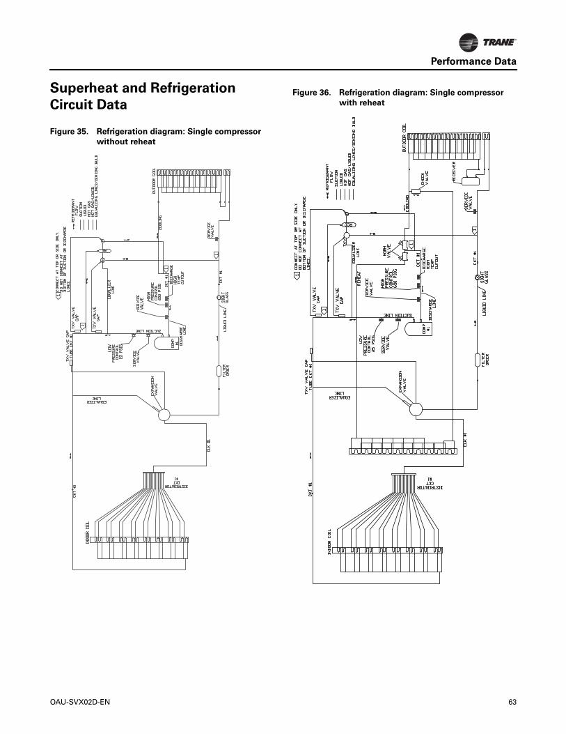
Performance Data
Superheat and Refrigeration
Circuit Data
Figure 35. Refrigeration diagram: Single compressor
without reheat
Figure 36. Refrigeration diagram: Single compressor
with reheat
OAU-SVX02D-EN 63

Performance Data
Figure 37. Refrigeration diagram: dual compressor
without reheat
Figure 38. Refrigeration diagram: dual compressor with
reheat
64 OAU-SVX02D-EN

Alarms and Troubleshooting
Microprocessor Control
The Main Unit Display and RTRM have the ability to provide the service personnel with some unit diagnostics and system status information.
1. Verify that the Liteport LED on the RTRM is burning continuously. If the LED is lit, go to Step 3.
2. If the LED is not lit, verify that 24 Vac is presence between J1-1 and J1-2. If 24 Vac is present, proceed to Step 3. If 24 Vac is not present, check the unit main power supply, check transformer (TNS1). Proceed to Step 3 if necessary.
3. Utilizing “Method 1” in the RTRM “System Status Checkout Procedure”, check the following:
• System status
• Cooling status
If a System failure is indicated, proceed to Step 4. If no failures are indicated, proceed to Step 5.
4. If a System failure is indicated, recheck Step 1 and Step 2. If the LED is not lit in Step 1, and 24 Vac is present in Step 2, the RTRM has failed. Replace the RTRM.
5. If no failures are indicated, use one of the override options to start the unit. Following the Override procedure will allow you to check all of the operating modes, and all of the external controls (relays, contactors, etc.) for each respective mode.
6. Refer to the sequence of operations for each mode, to assist in verifying proper operation. Make the necessary repairs and proceed to Step 7.
7. If no abnormal operating conditions appear in the Override mode, release the override and turn the power “Off” at the main power disconnect switch.
System Alarms
The Main Unit Display has built in alarms to help the operator troubleshoot system failures. This section will describe these alarms and provide a guide to troubleshooting the all unit operating modes.
Comprehensive system alarms and diagnostics are accessed through the Alarms icon at the unit display discussed later in the section, or through Tracer TU programming on connected computer. Sensor failures may be viewed through the Alarms icon.
If an alarm is present, the main indicator light on the UC600 will blink red. If the optional unit display is installed, the Alarm icon on the display will register ALARM, illuminate red and flash.
Important: The space temperature sensor (SPTC) and space relative humidity sensor (SPHC) will read failed if they are not connected; they will Alarm as “In Fault.”
Sensor Failure Alarm Display
Press the Alarm button on the Home display of the Unit Display to display system sensor status as described in Table 14 and Table 15, p. 66.
WARNING
Hazardous Service Procedures!
Failure to follow all precautions in this manual and on the tags, stickers, and labels could result in death or serious injury.Technicians, in order to protect themselves from potential electrical, mechanical, and chemical hazards, MUST follow precautions in this manual and on the tags, stickers, and labels, as well as the following instructions: Unless specified otherwise, disconnect all electrical power including remote disconnect and discharge all energy storing devices such as capacitors before servicing. Follow proper lockout/tagout procedures to ensure the power can not be inadvertently energized. When necessary to work with live electrical components, have a qualified licensed electrician or other individual who has been trained in handling live electrical components perform these tasks.
Table 14. TOAU UC600 alarms
Point Diagnostic Possible Cause
1 Indoor Fan Failure
VFD not operating
Outdoor and/or Return Air Dampers not Operating Properly
Indoor Fan Motor Failure
Indoor Fan Failure Switch IFFS (pressure) Failure
IFFS Tubing damaged or not properly connected
Refer to startup procedure
3 OAD Proving Switch
No voltage at actuator
Failed OAD power transformer
No continuity thru end switch (check at UC)
Note: If unit optional RA damper is installed, send switch on OAD is always proven
6Discharge Air Temp Source Failure
BAS communication down
Failed sensor or improper sensor installation
8 Fire Shutdown BAS ONLY
10 Low Temp Lockout
Heat Overridden OFF
Compressor(s) Overridden ON
Setpoint Failures Incorrect
DAT sensor malfunction
Reference Table 15, p. 66 for heat failure issues
OAU-SVX02D-EN 65

Alarms and Troubleshooting
11 Space Temp Source Failure
BAS communication down
Failed sensor or improper sensor installation
13 OA Temp Source Failure
BAS communication down
Failed sensor or improper sensor installation
14 OA Humidity Source Failure
BAS communication down
Failed sensor or improper sensor installation
Humidity Wiring is polarity sensitive
15 High Temp Lockout
Heat Overridden ON
Low discharge air volume
Dirty air filters
High gas heater manifold pressure
OA/RA damper position incorrect
High temp limit not properly installed or wired
DAT sensor malfunction
17 System LockoutCheck all Alarms
External safety device failed open
19 Space RH Source Failure
BAS communication down
Failed sensor or improper sensor installation
Humidity Wiring is polarity sensitive
32 ERV Leaving Air Condition Failure
Failed RH or temperature sensor
Incorrectly installed or connect RH or Temp sensor
42 Heat Failure
Applies to 5:1 and 10:1 Gas Heaters Only
Trips after heat command “ON” and no GV status offer 1 minute
Refer to unit “Service Facts” heat control LED status legend
No gas, low gas pressure or high gas pressure to unit
Unit Manual shutoffs closed
Heater inducer failure
Heat relay failure
Loose or incorrect wiring
Table 15. TOAU UC600 troubleshooting
Trouble Possible Cause
Unit Not Running
No power supply to unit disconnect switch
Power disconnect tripped
Lockout alarm mode
Emergency Stop condition exists
Unit in Unoccupied mode
Discharge air sensor failed or not installed and connected to unit
Table 14. TOAU UC600 alarms (continued)
Point Diagnostic Possible Cause
No Heat
No gas supply to unit
Unit manual gas valve(s) closed
Heater high limit tripped
Heat relay not energized
Conditions do not warrant call for heat
Heater control module malfunction
Roll out switch trip
Main gas on-off switch OFF
Inducer fan failure
Heater air proving switch not making or failed
No Compressor
Compressor limit switch(es) open
Compressor relay not energized or failed
Conditions do not warrant call for cooling or dehumidification
Wide Discharge Temp Swings
Discharge air sensor position must be at least 4 ft.-0 in. away from unit outlet
Min and Max gas heater manifold pressures not set correctly
Space too Hot, Cold or Humid
Setpoints not adjusted properly
Space sensors not correctly located or wired
Malfunctioning space sensor
IFM or PEX VFD OC Trip
Overcurrent alarm requires max Hz setting on VFD be checked and set to not exceed motor nameplate amps
EX VFD only run to Min HZ Setting
If supplied with RA pressure transducer and modulating damper setup is not installed or properly wired.
ERV Will Not RunERV leaving air temp below 34°F low temp cutout
Interlocked with Exhaust fan if exhaust is not running ERV will be OFF
Unit Trips Heater High Limit
High fire gas manifold pressure too high
Supply fan speed too low
Dirty or clogged filters
Restricted discharge air duct
Temperature of air entering heater too high
Defective high limit
Protonode Not Communicating Change Baud rate on UC600 to 38,400
Table 15. TOAU UC600 troubleshooting (continued)
Trouble Possible Cause
66 OAU-SVX02D-EN

Alarms and Troubleshooting
RTRM Failure Modes
Following is the listing of RTRM failure indication causes.
System Failure
Check the voltage between RTRM terminals 6 and 9 on J6, it should read approximately 32 Vdc. If no voltage is present, a System failure has occurred. Refer to Step 4 in “Microprocessor Control,” p. 65 for the recommended troubleshooting procedure.
Cooling Failure
• CLP1 has opened during the 3 minute minimum “on time” during four consecutive compressor starts, check CLP1 by testing voltage between the J1-8 and J3-2 terminals on the RTRM and ground. If 24 Vac is present, the CLP has not tripped. If no voltage is present, CLP has tripped.
System Failure
Measure the voltage between terminals J6-9 and J6-6.
Normal Operation = approximately 32 Vdc
System Failure = less than 1 Vdc, approximately 0.75 Vdc
Cool Failure
Measure the voltage between terminals J6-8 and J6-6.
Cool Operating = approximately 32 Vdc
Cool Off = less than 1 Vdc, approximately 0.75 Vdc
Cooling Failure = voltage alternates between 32 Vdc and 0.75 Vdc
WARNING
Live Electrical Components!
Failure to follow all electrical safety precautions when exposed to live electrical components could result in death or serious injury. When necessary to work with live electrical components, have a qualified licensed electrician or other individual who has been properly trained in handling live electrical components perform these tasks.
OAU-SVX02D-EN 67

Appendix
OAU Filter Guide
Table 16. OAB Units
EvaporatorThickness MERV Qty Height Width
2 in. 8, 13 2 20 24
4 in. 14 2 20 24
Auxiliary ModuleReturn AirThickness MERV Qty Height Width
2 in. 8 4 20 24
Outside Air(a)
(a) No filters will be provided on the outside air path of the auxiliary module if electric preheat is provided.
Thickness MERV Qty Height Width2 in. 8 4 20 24
Table 17. OAG Units
EvaporatorThickness MERV Qty Height Width
2 in. 8, 13 6 16 244 in. 14 6 16 24
Auxiliary ModuleReturn AirThickness MERV Qty Height Width
2 in. 8 6 16 24Outside Air(a)
(a) No filters will be provided on the outside air path of the auxiliary module if electric preheat is provided.
Thickness MERV Qty Height Width2 in. 8 6 16 24
68 OAU-SVX02D-EN

Appendix
Field Installation of Factory-
Provided Sensors
Figure 39. VELSEN-0021 installation instructions
OAU-SVX02D-EN 69

Appendix
Figure 40. BAYSENS036A installation instructions
70 OAU-SVX02D-EN

Appendix
Figure 41. MZVAV DSPS document
OAU-SVX02D-EN 71

Appendix
Figure 42. VELCON-0350 installation instructions for modulating OA/RA dampers w/economizer and an exhaust fan
72 OAU-SVX02D-EN

Appendix
Horizon™ Dedicated Outdoor Air Unit Startup Form
Date : __________________Job Name :_____________________________________________________________________ Address :_____________________________________________________________________
_____________________________________________________________________Serial Number: ________________________________ Tag : __________________________
Start up contractor : _____________________________________________________________ Address :_____________________________________________________________________
_____________________________________________________________________
1 . Is there any visible shipping damage? _____YES _____NO2. Is the unit level? _____YES _____NO3. Are the unit clearances adequate for service and operation? _____YES _____NO4. Do all access doors open freely and are the handles operational? _____YES _____NO 5 . Have all electrical connections been tested for tightness? _____YES _____NO 6 . Does the electrical service correspond to the unit nameplate? _____YES _____NO 7. On 208/230V units, has transformer tap been checked? _____YES _____NO 8. Have the damper assemblies been inspected? _____YES _____NO 9. Are the air filters installed with proper orientation? _____YES _____NO 10. Have condensate drain and p-trap been connected? _____YES _____NO 11. Have the crankcase heaters been on for 24 hrs. _____YES _____NO
Discharge temp Space Temp / HumiditySupply Duct Pressure Transducer Return Duct / Space Pressure Transducer
Quantity Orientatio n Clean
# L1 L2 L3 Amps1234
Factory supplied sensors installed
FiltersLocation
Pre Startup Checklist
Size
Installing contractor should verify the following items.
Program ControlNon Heat Pump: Discharge Space Single Zone VAV Multi Zone VAV Heat Pump: Discharge Space Single Zone VAV Multi Zone VAV
CompressorsModel Serial
p
OAU-SVX02D-EN 73

Appendix
Horizon™ Dedicated Outdoor Air Unit Startup Form
Wheel Spins freely Check Rotation FLA:Voltage L1: L2: L3: Amps: HP:
Ambient Dry Bulb Temperature_______°F Ambient Wet Bulb Temperature________°F
Water CooledNo water leaks Water Flow :_______________ GPMWater Inlet Temp :__________°F Water Outlet Temp: ___________°FAir Cooled L1 L2 L3 Amps HP
Pressure Sat Temperature Line Temperature Subcooling Super HeatDischarge
SuctionLiquid
Pressure Sat Temperature Line Temperature Subcooling Super HeatDischarge
SuctionLiquid
Pressure Sat Temperature Line Temperature Subcooling Super HeatDischarge
SuctionLiquid
Pressure Sat Temperature Line Temperature Subcooling Super HeatDischarge
SuctionLiquid
Refrigeration System --Circuit 1
Supply Fan Assembly
Power Exhaust Fan Assembly
Energy Recover Wheel Fan 2 - Alignment Name plate amps: Actual Amps: Rotation Hrtz:
Fan 2 - Alignment Name plate amps: Actual Amps: Rotation Hrtz: Fan 2 - Alignment Name plate amps: Actual Amps: Rotation Hrtz:
Operation check Two PositionModulating
Refrigeration System --Circuit 2
HEATING -- Refrigeration System (Heat Pump Only) --Circuit 1
HEATING -- Refrigeration System (Heat Pump Only) --Circuit 2
Condenser Configuration
Ambient Temperature
DampersDamper set up
Fan 1Fan 2Fan 3Fan 4
Fan 2 - Alignment Name plate amps: Actual Amps: Rotation Hrtz:
74 OAU-SVX02D-EN

Appendix
Horizon™ Dedicated Outdoor Air Unit Startup Form
1. Has the entire system been flushed and pressure checked? 2. Has the entire system been filled with fluid? 3. Has air been bled from the heat exchangers and piping? 4. Is the glycol the proper type and concentration (N/A if water)? 6. Has the water piping been insulated? 7. What is the freeze point of the glycol (N/A if water)?
Natural Gas Propane Purge Air from the linesLow Fire High Fire
Heat 1Heat 2Heat 3
Amps L1: L2: L3:Amps L1: L2: L3:
Electric Heat
Water / Glycol System_____YES NO_____
_____YES NO__________YES NO_____
_____YES NO__________YES NO__________YES NO_____
Gas Heat
Pre Heat:Primary:
OAU-SVX02D-EN 75
Ingersoll Rand (NYSE:IR) advances the quality of life by creating comfortable, sustainable and efficient environments.Our people and our family of brands—including Club Car®, Ingersoll Rand®, Thermo King® and Trane®—work togetherto enhance the quality and comfort of air in homes and buildings; transport and protect food and perishables; andincrease industrial productivity and efficiency. We are a global business committed to a world of sustainable progressand enduring results. For more information, visit www.ingersollrand.com.
Ingersoll Rand has a policy of continuous product and product data improvement and reserves the right to change design and specifications without notice.
We are committed to using environmentally
conscious print practices that reduce waste.
© 2016 Ingersoll Rand All rights reserved
OAU-SVX02D-EN 14 Oct 2016
Supersedes OAU-SVX02C-EN (12 Dec 2014)