installation of tunnels under railroad tracks at south ... · switches and special facilities in...
TRANSCRIPT

MASSACHUSETTS HIGHWAY DEPARTMENT
MASSACHUSETTS TURNPIKE AUTHORITY
CENTRAL ARTERY (I-93) / TUNNEL (I-90) PROJECT
INSTALLATION OF TUNNELS UNDER RAILROAD TRACKS
AT
SOUTH STATION; BOSTON, MA
By
Ronald D. O’Blenis Parsons Brinckerhoff
Boston, MA Tel (617) 951-6044 Fax (617) 772-7052

ABSTRACT
This paper discusses the evolution of the Central Artery/Tunnel Project design and installation of
multiple highway tunnels under railroad tracks of the Northeast Corridor at its terminus at South Station,
Boston, Massachusetts. A Project commitment was to progress all work over, under, or adjacent to railroad
facilities in a manner which maintains safe and efficient rail operations. Design changes described herein
for the tunnel installation were made to reduce the potential unique construction impacts associated with
the tunnel installation. These design developments enabled the successful installation of the highway
tunnels to be realized.
PROJECT DESCRIPTION
The Central Artery/Tunnel Project, located in Boston, includes the construction of tunnels for
Interstate 93 which is currently carried on viaduct through the center of the City; extension of Interstate 90
(the Massachusetts Turnpike) through South Boston to Logan Airport and Route 1A in East Boston via a
newly completed immersed tube tunnel across Boston harbor; and reconfiguration of the Interstate 93 and
Interstate 90 interchange to the south, and the Interstate 93 and Route 1/Tobin Bridge interchange to the
north (Figure 1). The Massachusetts Highway Department (MHD) directed preliminary and final design
and initial construction efforts. The Massachusetts Turnpike Authority (MTA), which will operate the
completed system, has assumed responsibility for completion of the Project. The Federal Highway
Administration funds a substantive portion of the Project and provides direct oversight of all aspects of the
Project.
The Project shares many of the same transportation corridors with the Massachusetts Bay
Transportation Authority’s (MBTA) commuter rail and transit systems. The most significant interface
between the MBTA and the Project is the installation of three I-90 highway tunnel sections (one each for
the eastbound and westbound mainlines and one for connecting Ramp D) under MBTA’s five mainline

tracks of the Northeast Corridor, also used by Amtrak, and three mainline tracks of MBTA’s Dorchester
Branch in the area where they converge and enter South Station (Figure 2). Construction of the tunnels is
included in the Project’s contract known as I-93/I-90 Interchange - Southbound (C09A4). The largest
tunnel is I-90 eastbound with a cross-section of 79 feet wide by 36 feet high. The segment under the rail
tracks will be over 350 feet long when installed. The depth to the top of the three tunnels below the top of
rail will range from a maximum of 24 feet to a minimum of 10 feet. (Figure 3)
The magnitude of the Project required that the design and construction of the Project be
progressed in individual sections. Bechtel/Parsons Brinckerhoff (B/PB), as Management Consultant to
MHD (and now MTA), completed preliminary design for each section of the entire Project. Final design
for individual sections was then developed by additional consultants under contract to MHD and managed
by B/PB.
JACKED TUNNEL METHOD DESIGN
Following the selection of the joint venture of Maguire/F.R. Harris as Section Design Consultant (SDC) for
final design, the SDC proposed to install the tunnels under the railroad tracks by jacking full-section tunnel
segments under the existing tracks at South Station. The tunnel sections would be constructed in excavated
pits adjacent to the tracks. (Figure 4) This method has been used successfully in other locations principally
outside the United States. The method minimized interdependence of work by the railroad to support
construction. Advance track improvements were required to increase operational flexibility to route trains
away from jacking pit construction adjacent to the rail tracks.
The area of the tracks was originally within Boston Harbor and is now on historic fill and adjacent
to the existing Fort Point Channel waterway. Geological conditions consist of bedrock located
approximately one hundred and twenty (120) feet below the surface. Approximately twenty (20) feet of
glacial deposits are on top of the bedrock followed by approximately seventy (70) feet of marine clay, then
approximately fifteen (15) feet of organic deposits support approximately fifteen (15) feet of historic fill
(Figure 5).

A principal issue with the use of the tunnel jacking method was the removal of obstructions
including, but not limited to timber piles and decking, granite blocks, concrete blocks, granite tunnel of an
abandoned depressed railroad track, previous seawalls, and a railroad bridge foundation. Since the tunnel
jacking method eliminates any relocation of the railroad tracks, the possibility of pre-excavation for
obstruction removal was eliminated mandating that all obstructions be removed from the face of the tunnel
as it is jacked. A metal jacking shield placed on the lead tunnel section would be constructed with multiple
cells that provide work stations at any location of the tunnel face for mining and obstruction
removal.(Figure 6) As excavation ahead of the cutting plate is not permitted, ground which supports and
surrounds obstructions must first be stabilized by both mechanical means and grouting prior to removal to
prevent unacceptable loss of ground with resulting excessive surface and subsurface movement. The
design for removal of the depressed trackway specified the soil underneath to be grouted to fill any voids
and provide support after its supporting piles are cut out in advance of the jacking. As noted above, the
tunnel jacking method requires that the soil face at the tunnel jacking shield be fully stabilized to allow the
face to stand fully unsupported. The proposed measures to stabilize the soil face included dewatering,
grouting, soil nailing, and use of retractable support grillage in each compartment of the jacking shield.
A soil stability test program in the area of the tunnel jacking confirmed the need for dewatering of
the granular materials prior to the tunnel penetrating the headwall at the start of jacking. The relatively
high gravity water table and close proximity to the Fort Point Channel dictated the design of grouted
ground water cut-off walls. As dewatering is not effective in the Boston Blue Clay, the use of soil nails
was proposed to stabilize the clay. These would be installed horizontally from the excavated pit through
the headwall and from within the tunnel shield as jacking is progressed.
The other major issue associated with tunnel jacking requiring mitigation was the predicted
settlement of railroad tracks of up to fourteen (14) inches during dewatering and tunnel jacking (Figure 7).
After extensive discussions with MBTA and Amtrak officials, it was agreed that a program for monitoring
and controlling this rate of settlement, combined with an active program for re-ballasting and re-leveling
the tracks, would be an acceptable means to allow the jacking to occur and maintain railroad operations.
To define the limits of track movements and required responses for the jacking contractor and the railroads,
a Track Monitoring Flowchart (Figure 8), using the Federal Railroad Administration Track Safety

Standards as a basis, was developed that identified three categories of required responses based on track
movements. The green condition requires no immediate action, the amber condition requires the contractor
to initiate actions to minimize further ground movements to allow for re-ballasting and re-leveling during
non-peak traffic hours, and red defines emergency conditions requiring immediate actions by the contractor
to prevent further ground movements and mandating immediate action by the railroads to restore
acceptable track conditions or impose restrictions on train operations. The speed of trains in the area of the
tunnel tracking was 15 mph for passenger trains. No freight trains operate in the area. The limits that
correspond to green, yellow, or red conditions were established to allow identification of track locations
that were experiencing movement caused by construction. The limits were not established to correspondent
to any specific limits of an FRA track Safety Standard class. It was intended that the indications would
normally be used to schedule track maintenance by railroad forces. The emergency condition criterion was
established to identify when immediate action was required by the Contractor, the Resident Engineer and
the Railroad. The emergency condition would require stoppage of all trains and cessation of tunnel
tracking operations. During tunnel jacking operations, railroad track foreman qualified to inspect track was
assigned to be on site. To facilitate communication between all parties, a daily meeting was held with
representatives from the Contractor, the Resident Engineer, the Project’s Geotechnical Engineer, and the
Railroad. During the daily meetings construction activity for the day and planned construction for the next
three days were reviewed, ground movements have evaluated, and planned track maintenance by railroad
forces was scheduled.
To provide track measurements for the Track Monitoring Flowchart, the Project surveyed tracks
up to three times per day. The survey data was inputted to a specifically designed computer program which
performs the track movement calculations and displays the track geometry information of the Track
Monitoring Flowchart by locations and the green, amber, and red criteria. The monitoring program was
available to the Railroads, Contractor, and Resident Engineer staff (Figure 9). To respond to predicted and
unexpected track settlements, the Contractor was required to develop and implement specific mitigation
measures to prevent track settlements from reaching emergency (red) conditions. To mitigate impacts to
railroad operations caused by track settlements, railroad forces and equipment were assigned directly to the
Project to insure immediate response for required track maintenance.

The CA/T Project contract for the tunnel jacking work was bid in late 1996 and the mitigation
measures discussed above where integrated into the contract documents. A final mitigation measure
deemed necessary to provide for successful installation of the tunnel was a requirement for prequalification
of the tunnel jacking subconsultant based on previous experience in tunnel jacking. As the tunnel jacking
effort would be the largest and most complex installation to date, the prequalification specification was
implemented to guarantee that an experienced contractor and staff would be directing the actual jacking
operation
CONTRACTOR VECP PROPOSAL - GROUND FREEZING
Following award of the CA/T Project C09A4 contract to the joint venture of Slattery, Interbeton,
J.F. White & Perini (SWIP), the Contractor submitted a Value Engineering Cost Proposal (VECP) to
stabilize the soil by use of ground freezing. The VECP was recommended as a means to achieve maximum
security for railroad infrastructure and operations by significantly increasing the strength and stability of
the soil at the tunnel jacking face. Following evaluation by the Project and Railroad staff, it was agreed
that the freezing method would result in a more predictable and controllable construction method. The use
of ground freezing was used to replace all stabilization methods identified in the baseline design. The
freezing method increased the efficiency of obstruction removal by holding obstructions in place.
Although, the freezing method positive benefits associated with tunnel jacking, it still required mitigation
to address issues unique to its installation.
The major issue that threatened approval of the ground freezing proposal was the heaving of the
soil caused by ground freezing which in turn would lift the railroad tracks. Settlement of tracks, as
anticipated in the Final Design, could be handled by re-ballasting and surfacing (raising) the tracks.
However, lowering of tracks necessary to maintain rail profiles during the freezing process could not be
accomplished except by undercutting of the tracks. The substantial amount of switches, double slip
switches and special facilities in the area of the jacked tunnels precluded the use of mechanical track
undercutting equipment. The option of track removal, excavating ballast, and replacing the track was

determined to be impractical because the effort would require significantly more time than would be
available and the expense would be unacceptable. MBTA and Amtrak performed an analysis of the
maximum heave that could be accommodated by raising tracks in the approach areas to the zone of freezing
and determined that a maximum of seven (7) inches would be allowed. However, the prediction of
maximum heave ranged from a low of 3.2 inches to a maximum of 11.7 inches. Acceptance of the ground
freezing proposal was reached following development by the C09A4 contractor of a contingency plan to
control the heave and insure that the heave did not exceed seven (7) inches. The solution, to be
implemented if observations of the actual heaving produce trends over seven (7) inches, was to provide the
ability to shorten every other vertical freeze pipe. The effect of this would be to create staggered patterns
of frozen ground and reduce heave associated with the completely frozen condition. The staggered pattern
would avoid open pathways of unfrozen ground thereby maintaining the desired stabilized tunnel jacking
face.
The installation of freeze pipes was also presented a major obstacle to utilization of ground
freezing. To freeze the ground vertical pipes to carry chilled brine needed to be installed approximately six
feet on center over the entire area through which the jacked tunnels would pass. This required placement of
freeze pipes in the track areas. The vertical pipes also needed to be connected with supply lines to circulate
the chilled brine (Figure 10). The placement of freezing pipes was developed and mockups of the
installation were made on out of service track adjacent to live track areas. The installation was further
complicated by the addition of a catenary system for Amtrak’s Northeast Corridor Electrification Project.
The installation of the catenary system required substantial advance coordination and planning with Amtrak
and its electrification design-builder. Specific interface items included placement of catenary portal frame
supports on tunnel jacking pit walls and installation of sleeves in catenary portal spread footings to allow
installation of freeze pipes through the footing.
In working with the Railroads, it was determined that a maximum leave of seven inches could be
accepted. This would allow for limited surfacing to maintain cross-level and adjust profile as required.
The critical areas for heave were the EB and WB tunnels as they were located close to the Dorchester
Railroad Bridge over the Fort Port Channel. This was considered a fixed point for determining maximum
heave. Actual heave from freezing was 8.3 inches at Ramp D, and I-90 EB and I-90 WB was 4 inches and

4.6 inches respectively. The higher heave at Ramp D was accommodated by selective surfacing by railroad
forces.
TUNNEL JACKING INSTALLATION
The full width tunnel sections were constructed in pits excavated adjacent to the railroad tracks.
The pits also acted as thrust pits for the hydraulic jacks used to move the tunnel sections forward (Figure
11). The thrust pits were constructed using slurry wall techniques. The floors of the jacking pits consisted
of heavily reinforced concrete slabs. The tunnels were constructed in lengthwise sections. Intermediate
jacking stations were installed between the sections. This allowed individual sections to be jacked in a
sequential manner. By jacking individual sections, the total jacking force could be reduced and additional
control of the jacking alignment was realized. To minimize jacking forces and prevent horizontal
movement of soil above the tunnels, an anti-drag system was employed. This system utilizes a series of
cables that were threaded through the front of the tunnel and to the top of the tunnel. The cables were
placed adjacent to each other to form a continuous interface between the tunnel roof and the soil above.
Lubricant was applied to the cables to assist with the sliding of the cables over the top of the tunnels. A
second series of cables was utilized on the bottom of the tunnel to reduce friction between the supporting
soil and the bottom of the tunnel.
The front of each tunnel section was fitted with a steel shield. The shield was divided into six
compartments configured two vertically and three horizontally. This allowed individual work platforms
from which the frozen soil was excavated. The removal of soil and most obstructions was done utilizing
mining machines with a rotary cutting head (Figure 12). Obstructions included wood pilings and brick
seawalls.
The primary hydraulic jacks were located at the base of the tunnel section. For each of the
tunnels, 25 primary jacks were used. Each jack had a stroke of 42 inches. Intermediate jacks between
tunnel sections varied between 26 and 32. The primary jacks remained in place as the tunnel jacking
progressed. At the completion of a push, the hydraulic rams were retracted and spacers were placed
between the jacks and the base of the tunnels. The jacking of the tunnels was made after sufficient soil or
obstructions had been excavated in front of the shield at the face of the tunnel. Typical jacking progress

was 3 ft per 24 hours. The work progressed six days per year utilizing two crews working 10 hours per
shift.
The first tunnel to be jacked was Ramp D. It was installed between October 9, 1999 and
December 10, 1999. The I-90 EB and WB tunnels were installed between May 31, 2000 and February 5,
2001.
CONCLUSION
The installation of highway tunnels under the tracks at South Station remains was one of the most
challenging aspects of the Central Artery/Tunnel Project. The absolute requirement for maintenance of
railroad operations, combined with the safe and economical construction of the tunnels, mandated that the
design of the installation be constantly evaluated. As discussed above, the substantive and joint effort of
the design teams, railroads, and contractor to evaluate and improve the design resulted in a plan that all
parties agree managed risks (Figure 13). All parties involved were proud that the goals for the safe,
economical, and timely installation of the highway tunnels at South Station were realized.
ACKNOWLEDGMENTS
The author acknowledges the Massachusetts Highway Department, the Massachusetts Turnpike Authority,
the Federal Highway Administration, and the Management Consultant, Bechtel/Parsons Brinckerhoff, for
the organizations’ support in preparation of this paper.
Figure Captions
Figure 1 Central Artery/Tunnel Project Construction
Figure 2 Approaches to South Station
Figure 3 L to R Ramp D, I-90 Westbound, and I-90 Eastbound Tunnels
Figure 4 Tunnel Jacking Pits
Figure 5 Geologic Profile
Figure 6 Tunnel Jacking Operations Diagram
Figure 7 Predicted Settlement Contours
Figure 8 Track Monitoring Limits and Responses
Figure 9 Computer Output of Railroad Monitoring
Figure 10 Freeze Pipe Installation
Figure 11 Jacking Pits
Figure 12 Frozen Ground Excavation
Figure 13 Successful I-90 Eastbound Installation

Figure 1 Central Artery/Tunnel Project Construction

Figure 2 Approaches to South Station

Figure 3 L to R Ramp D, I-90 Westbound, and I-90 Eastbound Tunnels
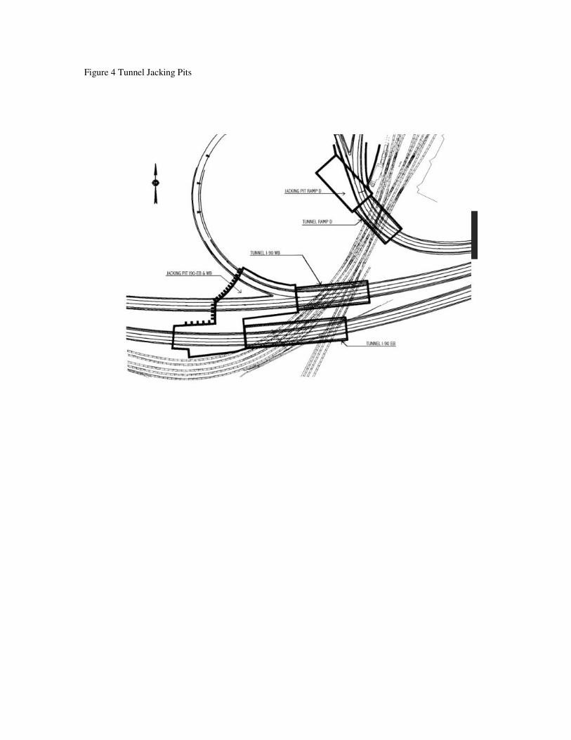
Figure 4 Tunnel Jacking Pits

Figure 5 Geologic Profile

Figure 6 Tunnel Jacking Operations Diagram

Figure 7 Predicted Settlement Contours

Figure 8 Track Monitoring Limits and Responses

Figure 9 Computer Output of Railroad Monitoring

Figure 10 Freeze Pipe Installation
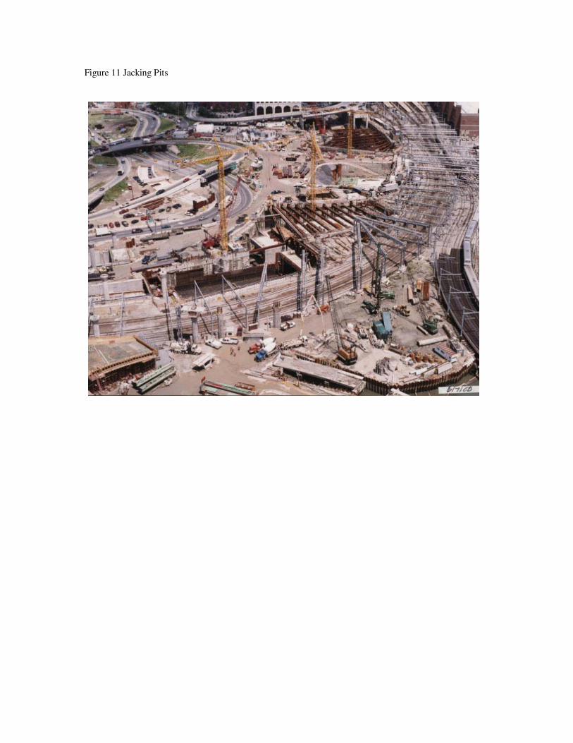
Figure 11 Jacking Pits

Figure 12 Frozen Ground Excavation

Figure 13 Successful I-90 Eastbound Installation