installation instructions: tummy tucker™ – tj rubicon models
TRANSCRIPT

Installation Instructions: Tummy Tucker™ – TJ Rubicon models
Nth30116 v4.doc page 1 of 13 download @ www.nthdegreemobility.com
Note: Transfer Case Clearances. There is no ‘magic’ to gaining ground clearance. The significant ground clearance gains that the Tummy Tucker skid plate provides are accomplished by ‘tucking things up’ by reducing some of the space between the floor pan, powertrain (trans and t-case), and the skid plate to the bare minimums (usually ¼ to 3/8”). To do this we have designed several different application-specific TT’s, but even with this level of ‘custom fit’, the substantial factory-build variation from one Wrangler to the next may cause you to encounter ‘touch’ conditions that require minor adjustments – these are your responsibility to correct as Nth° has made every effort to assure that the TT will fit perfectly on the Wrangler years and models it was designed for. Be especially aware that the frames of ’03-‘06 TJ’s are extremely variable in dimension compared to previous years, with brackets and holes that can be significantly out of position compared to Jeep’s own CAD models (which were used to design the TT). There is an appendix of solutions to known issues that have been encountered in a few cases.
Also - if everything is adjusted properly - you should not have any contact issues during normal driving even though clearances around the t/case are reduced with the TT. Do not drive your Jeep with the t-case rubbing either the floor or TT for extended periods – trans or t-case failure may eventually result! Unless you are using enough body lift, installation of a Tummy Tucker on a Rubicon TJ requires floor modifications (see table in step 4).
Kit Part Numbers TT14021 (Rubicon TJ/LJ with manual trans) TT14031 (Rubicon TJ/LJ with automatic trans)
Vehicle App’s ‘03+ TJ Wrangler and Unlimited Rubicon models ONLY The frame rails are unmodified in the area of the stock center skid plate. Any lift kit being used does not require center skid plate-mounted control arms. A double-Cardan (incorrectly aka ‘CV’) rear drive shaft is installed and the pinion angle adjusted for use of this drive shaft via a Stinger or adjustable rear control arms, etc. (If you have ZERO suspension lift on your Rubicon, you can use the stock driveshaft). An original Rubicon transmission is used: NV3550 (5-spd. manual), or 42RLE (4-spd. auto.)
Assumptions Equipment that must already be present on your Wrangler
The standard-for-Rubicon NV241J ‘Rock-Trac’ transfer case is used. Floor jack and ~12” piece of 4x4 post (or vehicle lift with a tall jackstand) Set of Allen ‘hex drive’ keys (including 8mm). Long pry bar or equivalent (autos only)
Required Tools and Equipment (in addition to common hand tools) Ratchet Strap, rope, etc. (see step 4) NOTE: If you have anything other than a ’03-06 TJ Wrangler Rubicon with the original trans and NV241OR ‘Rock Trac’ t-case, you have the wrong instructions (make sure you don’t also have the wrong TT!). To install a special TT with an NV241OR t-case in an older Wrangler, you need to follow the instructions for your model year and can follow step 4 of these instructions to perform the required floor modification if not using a body lift. Please take the time to read these instructions completely before beginning – they are long because we want you to get the installation right the first time with no unnecessary delays. Do not start or attempt this product installation if you are unsure of your abilities or do not have the resources listed below. If applicable, be sure to have all welding done by a certified person, and check/set all specified torques with a torque wrench…too tight is not just right!!
Step 1: Unpack boxes; Check contents against packing list; Verify parts in good condition. Be especially sure that you have the right parts for your application! Step 2: Read all of the following instruction steps before beginning! Do not disassemble vehicle unless all parts are present and all tools and facilities required are available.
Installation Instructions: Tummy Tucker™ – TJ Rubicon models
Nth30116 v4.doc page 2 of 13 download @ www.nthdegreemobility.com
Fig. 1
Fig. 2
Fig. 3
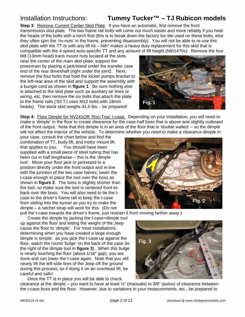
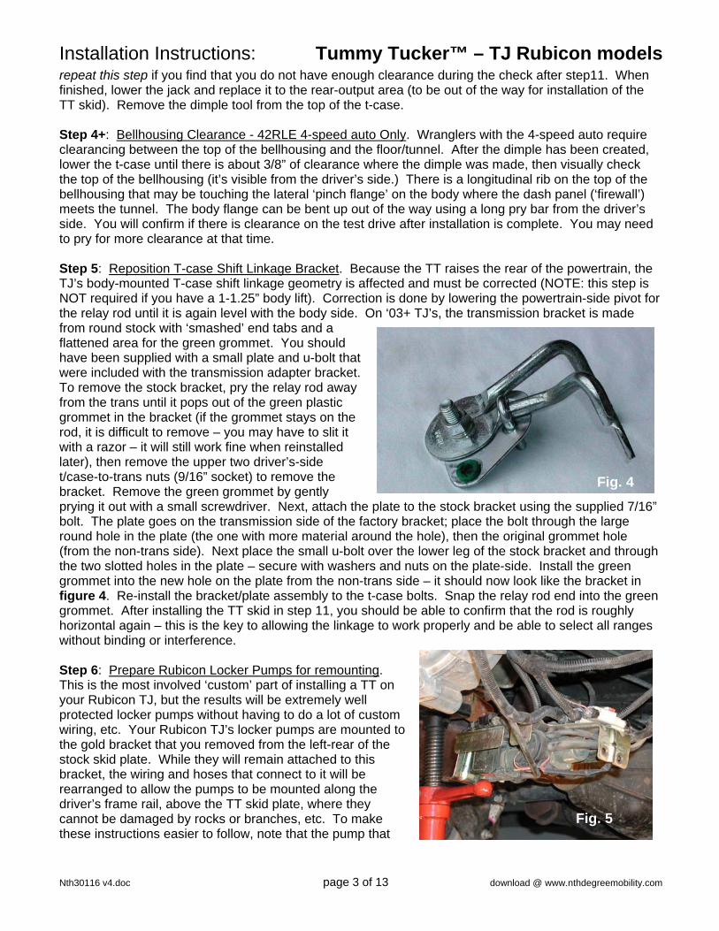
Step 3: Remove Current Center Skid Plate. If you have an automatic, first remove the front transmission skid plate. The two frame rail bolts will come out much easier and more reliably if you heat the heads of the bolts with a torch first (this is to break down the factory loc-tite used on these bolts, else they often spin the ‘riv-nuts’ in the frame, preventing disassembly). You will not be able to re-use this skid plate with the TT or with any lift kit – Nth° makes a heavy duty replacement for this skid that is compatible with the 4-speed auto-specific TT and any amount of lift height (Nth1470x). Remove the four M8 (13mm head) trans mount nuts located at the slots near the center of the main skid plate; support the powertrain by placing a jack/stand under the transfer case end of the rear driveshaft (right under the joint). Next, remove the four bolts that hold the locker pumps bracket to the left-rear area of the skid and support the assembly with a bungie cord as shown in figure 1. Be sure nothing else is attached to the skid plate such as auxiliary air lines or wiring, etc. then remove the six bolts that attach the plate to the frame rails (’03 TJ uses M12 bolts with 18mm heads). The stock skid weighs 41.5 lbs. - be prepared! Step 4: Floor Dimple for NV241OR ‘Roc-Trac’ t-case. Depending on your installation, you will need to make a ‘dimple’ in the floor to create clearance for the case-half boss that is above and slightly outboard of the front output. Note that this dimple is in an area of the floor that is ‘double walled’ – so the dimple will not affect the interior of the vehicle. To determine whether you need to make a clearance dimple in your case, consult the chart below and find the combination of TT, body lift, and motor mount lift that applies to you. You should have been supplied with a small piece of steel tubing that has been cut in half lengthwise – this is the ‘dimple tool’. Move your floor jack or jackstand to a position directly under the front output and in line with the junction of the two case halves; lower the t-case enough to place the tool over the boss as shown in figure 2. The boss is slightly shorter than the tool, so make sure the tool is centered front-to-back over the boss. You will also need to tie the t-case to the driver’s frame rail to keep the t-case from sliding into the tunnel as you try to make the dimple – a ratchet strap will work for this. (Do not pull the t-case towards the driver’s frame, just restrain it from moving farther away.)
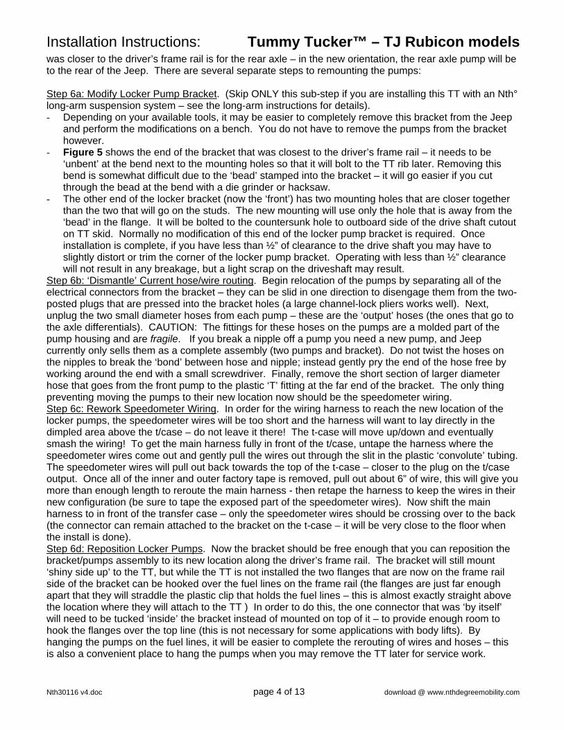
Create the dimple by jacking the t-case+dimple tool up against the floor and letting the weight of the Jeep cause the floor to ‘dimple’. For most installations, determining when you have created a large enough dimple is simple: as you jack the t-case up against the floor, watch the round ‘bulge’ on the back of the case (to the right of the dimple tool in figure 3). When this bulge is nearly touching the floor (about 1/16” gap), you are done and can lower the t-case again. Note that you will nearly lift the left-side tires of the Jeep off the ground during this process, so if doing it on an overhead lift, be careful and safe!
Once the TT is in place you will be able to check clearance at the dimple – you want to have at least ¼” (manuals) to 3/8” (autos) of clearance between the t-case boss and the floor. However, due to variations in your measurements, etc., be prepared to
Installation Instructions: Tummy Tucker™ – TJ Rubicon models
Nth30116 v4.doc page 3 of 13 download @ www.nthdegreemobility.com
Fig. 4
Fig. 5
repeat this step if you find that you do not have enough clearance during the check after step11. When finished, lower the jack and replace it to the rear-output area (to be out of the way for installation of the TT skid). Remove the dimple tool from the top of the t-case. Step 4+: Bellhousing Clearance - 42RLE 4-speed auto Only. Wranglers with the 4-speed auto require clearancing between the top of the bellhousing and the floor/tunnel. After the dimple has been created, lower the t-case until there is about 3/8” of clearance where the dimple was made, then visually check the top of the bellhousing (it’s visible from the driver’s side.) There is a longitudinal rib on the top of the bellhousing that may be touching the lateral ‘pinch flange’ on the body where the dash panel (‘firewall’) meets the tunnel. The body flange can be bent up out of the way using a long pry bar from the driver’s side. You will confirm if there is clearance on the test drive after installation is complete. You may need to pry for more clearance at that time. Step 5: Reposition T-case Shift Linkage Bracket. Because the TT raises the rear of the powertrain, the TJ’s body-mounted T-case shift linkage geometry is affected and must be corrected (NOTE: this step is NOT required if you have a 1-1.25” body lift). Correction is done by lowering the powertrain-side pivot for the relay rod until it is again level with the body side. On ‘03+ TJ’s, the transmission bracket is made from round stock with ‘smashed’ end tabs and a flattened area for the green grommet. You should have been supplied with a small plate and u-bolt that were included with the transmission adapter bracket. To remove the stock bracket, pry the relay rod away from the trans until it pops out of the green plastic grommet in the bracket (if the grommet stays on the rod, it is difficult to remove – you may have to slit it with a razor – it will still work fine when reinstalled later), then remove the upper two driver’s-side t/case-to-trans nuts (9/16” socket) to remove the bracket. Remove the green grommet by gently prying it out with a small screwdriver. Next, attach the plate to the stock bracket using the supplied 7/16” bolt. The plate goes on the transmission side of the factory bracket; place the bolt through the large round hole in the plate (the one with more material around the hole), then the original grommet hole (from the non-trans side). Next place the small u-bolt over the lower leg of the stock bracket and through the two slotted holes in the plate – secure with washers and nuts on the plate-side. Install the green grommet into the new hole on the plate from the non-trans side – it should now look like the bracket in figure 4. Re-install the bracket/plate assembly to the t-case bolts. Snap the relay rod end into the green grommet. After installing the TT skid in step 11, you should be able to confirm that the rod is roughly horizontal again – this is the key to allowing the linkage to work properly and be able to select all ranges without binding or interference. Step 6: Prepare Rubicon Locker Pumps for remounting. This is the most involved ‘custom’ part of installing a TT on your Rubicon TJ, but the results will be extremely well protected locker pumps without having to do a lot of custom wiring, etc. Your Rubicon TJ’s locker pumps are mounted to the gold bracket that you removed from the left-rear of the stock skid plate. While they will remain attached to this bracket, the wiring and hoses that connect to it will be rearranged to allow the pumps to be mounted along the driver’s frame rail, above the TT skid plate, where they cannot be damaged by rocks or branches, etc. To make these instructions easier to follow, note that the pump that
Installation Instructions: Tummy Tucker™ – TJ Rubicon models
Nth30116 v4.doc page 4 of 13 download @ www.nthdegreemobility.com
was closer to the driver’s frame rail is for the rear axle – in the new orientation, the rear axle pump will be to the rear of the Jeep. There are several separate steps to remounting the pumps: Step 6a: Modify Locker Pump Bracket. (Skip ONLY this sub-step if you are installing this TT with an Nth° long-arm suspension system – see the long-arm instructions for details). - Depending on your available tools, it may be easier to completely remove this bracket from the Jeep
and perform the modifications on a bench. You do not have to remove the pumps from the bracket however.
- Figure 5 shows the end of the bracket that was closest to the driver’s frame rail – it needs to be ‘unbent’ at the bend next to the mounting holes so that it will bolt to the TT rib later. Removing this bend is somewhat difficult due to the ‘bead’ stamped into the bracket – it will go easier if you cut through the bead at the bend with a die grinder or hacksaw.
- The other end of the locker bracket (now the ‘front’) has two mounting holes that are closer together than the two that will go on the studs. The new mounting will use only the hole that is away from the ‘bead’ in the flange. It will be bolted to the countersunk hole to outboard side of the drive shaft cutout on TT skid. Normally no modification of this end of the locker pump bracket is required. Once installation is complete, if you have less than ½” of clearance to the drive shaft you may have to slightly distort or trim the corner of the locker pump bracket. Operating with less than ½” clearance will not result in any breakage, but a light scrap on the driveshaft may result.
Step 6b: ‘Dismantle’ Current hose/wire routing. Begin relocation of the pumps by separating all of the electrical connectors from the bracket – they can be slid in one direction to disengage them from the two-posted plugs that are pressed into the bracket holes (a large channel-lock pliers works well). Next, unplug the two small diameter hoses from each pump – these are the ‘output’ hoses (the ones that go to the axle differentials). CAUTION: The fittings for these hoses on the pumps are a molded part of the pump housing and are fragile. If you break a nipple off a pump you need a new pump, and Jeep currently only sells them as a complete assembly (two pumps and bracket). Do not twist the hoses on the nipples to break the ‘bond’ between hose and nipple; instead gently pry the end of the hose free by working around the end with a small screwdriver. Finally, remove the short section of larger diameter hose that goes from the front pump to the plastic ‘T’ fitting at the far end of the bracket. The only thing preventing moving the pumps to their new location now should be the speedometer wiring. Step 6c: Rework Speedometer Wiring. In order for the wiring harness to reach the new location of the locker pumps, the speedometer wires will be too short and the harness will want to lay directly in the dimpled area above the t/case – do not leave it there! The t-case will move up/down and eventually smash the wiring! To get the main harness fully in front of the t/case, untape the harness where the speedometer wires come out and gently pull the wires out through the slit in the plastic ‘convolute’ tubing. The speedometer wires will pull out back towards the top of the t-case – closer to the plug on the t/case output. Once all of the inner and outer factory tape is removed, pull out about 6” of wire, this will give you more than enough length to reroute the main harness - then retape the harness to keep the wires in their new configuration (be sure to tape the exposed part of the speedometer wires). Now shift the main harness to in front of the transfer case – only the speedometer wires should be crossing over to the back (the connector can remain attached to the bracket on the t-case – it will be very close to the floor when the install is done). Step 6d: Reposition Locker Pumps. Now the bracket should be free enough that you can reposition the bracket/pumps assembly to its new location along the driver’s frame rail. The bracket will still mount ‘shiny side up’ to the TT, but while the TT is not installed the two flanges that are now on the frame rail side of the bracket can be hooked over the fuel lines on the frame rail (the flanges are just far enough apart that they will straddle the plastic clip that holds the fuel lines – this is almost exactly straight above the location where they will attach to the TT ) In order to do this, the one connector that was ‘by itself’ will need to be tucked ‘inside’ the bracket instead of mounted on top of it – to provide enough room to hook the flanges over the top line (this is not necessary for some applications with body lifts). By hanging the pumps on the fuel lines, it will be easier to complete the rerouting of wires and hoses – this is also a convenient place to hang the pumps when you may remove the TT later for service work.

Installation Instructions: Tummy Tucker™ – TJ Rubicon models
Nth30116 v4.doc page 5 of 13 download @ www.nthdegreemobility.com
Fig. 6
Fig. 7
Step 6e: Rearrange Wiring. As you may have already done at this point, some of the wires leading to and from the four connectors that were mounted to the locker pump bracket can be unplugged and rerouted around each other to better suit the new location. Once this is done, the wires will need to be zip-tied to the frame-mounted fuel/brake lines. Step 6f: Reroute Hoses. There are some simple modifications to allow the hoses to reconnect: - remove the large (about 1”) diameter plastic ‘convolute’ sheathing that holds the rear locker pump
hose and wires along with the larger air intake hose coming from the fuel filler area. By zip-tying the intake hose to the fuel and brake lines along the driver’s frame rail, you can ‘save’ a large amount of this intake hose length – it will be more than enough to reattach it to the plastic ‘T’ at the back of the locker pump bracket. You may need to gently pull a little extra length from above the fuel tank as well. There will be enough to allow you to cut off about 3” of extra hose.
- Use the 3” of intake hose plus the supplied ¼” barbed union fitting to reconnect the front locker pump to the plastic ‘T’ (The ‘T’ should be at the very back of the bracket, with the rear locker hose straight out instead of bent 90 degrees as it was originally). Secure the remaining small hose and wires that go to the rear axle along the left-rear upper control arm or as appropriate to allow full suspension motion, etc.
- Next, cut 7.5” off of the small diameter hose going to the front axle and reattach it to the front locker pump – you will need to remove the last tape wrap and turn the hose around 180 degrees to fit onto the pump.
- Use the 7.5” piece of small tubing and the supplied 3/16” barbed union fitting to extend the rear locker’s small hose. This should make the rear hose long enough to reattach to the rear locker pump.
Figure 6 shows how everything should be hooked up again, with nothing stretched too tight or hanging where it could be damaged. Ideal routing of the various harnesses should be apparent and can be held in place with a few added zip-ties. It is especially recommended to make sure that none of the hoses/lines are hanging free and close to where they could get tangled in the front drive shaft – if you keep everything ‘inside’ the locker bracket’s flanges, you will not have any problems. Final attachment to bracket to the TT will occur in step 12 after the TT is bolted in. Step 7: Remove Stock Transmission Mount. Remove the four bolts that attach the bracket to the rear-underside of the transmission (5/8” heads) – there is no need to remove the isolator itself from the adapter bracket. Once the bracket is loose, slide it rearward until the exhaust steady rest isolator slips off of the hanger pin (solid rod that is welded to the pipe ahead of the catalytic converter.) These parts will not be reused with the TT. Step 8: Remove exhaust hanger bushing. You will re-use the exhaust steady rest isolator bushing from the original bracket. To remove it, note that the rear (as it was installed on the Jeep) end of the isolator has a smaller lip on it than the front – push the isolator out from this end towards the front using a ¾” socket (using a larger socket will shear off the small lip). Replace the isolator in the same orientation in the tube on the new bracket – it will be much easier if white-lithium grease is sprayed inside the tube. See figure 7 for completed conversion orientation.

Installation Instructions: Tummy Tucker™ – TJ Rubicon models
Nth30116 v4.doc page 6 of 13 download @ www.nthdegreemobility.com
NOTE: If you are installing this TT with either an Nth° long-arm system or you have a motor mount lift, you will need to add ‘shim washers’ (large diameter washers supplied with this kit) between the top of the isolators and the bracket. For Nth° long-arm add two washers per side; for motor lifts add at least 3 per side – if you have both you will need 4-5 washers per side. This is necessary to keep the t-case from contacting the TT under the front-output area.
Auto Brkt.
Manual Brkt.
Low style ’87-’02 MY
High style ’03-’06 MY
Step 9: Pre-assemble New Transmission Mount Adapter Brackets. The new mount supplied with the TT has two parts – the main bracket to connect the two new isolators to the trans, and a bolt-on extension for the exhaust ‘steady rest’ tube. There are two main types of trans brackets: one for all factory autos, and one for all factory manual trans used with 4.0L engines (there is also a different bracket for AX-5 manuals). The exhaust extension comes in two styles: ‘low’ for ’02-older vehicles, and ‘high’ for ’03-06 TJs. Consult the pictures below to confirm that you have the correct brackets for your vehicle (trans
brackets show the bottom side with front of vehicle at top of picture; exhaust brackets shown from ‘trans side’ of bracket with front of vehicle towards left side of picture.)
For pre-assembly, either extension can be bolted to either trans mount in two positions depending on your application: inboard (closer to trans) for use with Nth° long-arm suspensions, and outboard for ‘stock position’ to be used with Nth° short-arm or any other suspension systems. Pre-assemble the exhaust extension to the main bracket with one 3/8” x 1” bolt and nut through the appropriate non-slotted hole in the main bracket.
The isolators are mounted differently for the left (driver’s) and right sides. For the driver’s side, place a lock washer and then a flat washer on the remaining 3/8”x1” bolt, then pass the bolt from the top side of the slotted hole in the bracket and thread it into the hole on the top (rubber side) of the isolator (for autos, ignore the extra forward slot on this side – use the one directly across from the passenger-side slot). For the passenger side, you must first drill out the threads in the center hole of the isolator to 3/8”, then place the provided socket head bolt up through the drilled-out hole from the bottom of the isolator and press the head of the bolt into the hex-shaped void in the rubber. Position the isolator under the passenger-side slot and add the ‘flag nut’ to the bolt on the top side.

Installation Instructions: Tummy Tucker™ – TJ Rubicon models
Nth30116 v4.doc page 7 of 13 download @ www.nthdegreemobility.com
Figure 8 Figure 9
Figure 10
Figure 11
Figure 8 shows an auto bracket with a high-type exhaust extension in the Nth° long-arm (inboard position) – Figure 9 shows a manual bracket with the low-type exhaust extension in the ‘standard’
position – other combinations will look similar. Orient each isolator to roughly match the orientation of the holes on the TT skid and leave the bolts only finger tight for now as shown in figure 10. Step 8: Install the new Trans Mount Assembly to the trans in the same manner that the original one was removed. This will be easiest if you increase the height of the jack under the transfer case output so that the trans is higher relative to the exhaust than it was stock. Start all bolts by hand, then torque to 50 ft-lbs. Figure 11 shows a mount installed on a TJ Rubicon with 4-speed automatic. Notes for specific transmissions – 42RLE Automatics re-use the original four
bolts. – NV3550 (5-speed manual): Replace the
original four bolts with the supplied 7/16x1”L flathead bolts.
– NSG-370 (6-speed manual): Replace the original four bolts with the supplied M10x25mm bolts – make sure to distinguish these from the 7/16” flathead bolts that look similar but will not fit!
Step 11: Attach TT Main Skid Plate. Confirm that you were supplied the correct fasteners by laying the threaded portion of one against the threads of an original bolt – they must ‘mesh’ exactly (’97-02 TJ’s use ½-13 SAE bolts; ‘03+ TJ’s use M12 metric bolts). Elevate the powertrain all the way up against the floor for this step. Before raising the TT into position, check the positioning of the exhaust. If the hanger at the back of the muffler is no longer hanging (meaning the muffler is too high), loosen the two nuts on the flange just ahead of the muffler until the rear portion of the exhaust again hangs from the rubber mounts behind the muffler and at the tailpipe (you may need to bend the hanger rods slightly to get them to hang fully). Next, confirm that the isolators are ‘clocked’ to roughly align with the holes in the skid. Before raising the skid into position, install the two 5/16” bolts into the holes at the driver’s-side end of the main (lateral) rib – these will be used to re-mount the locker pump bracket with two additional nuts later. The bolts must go in from the front side of the rib and be secured with two nuts on the backside as shown in figure 12 - it will be helpful to use lock-tite. Next raise the TT into position (make sure the isolators didn’t hang up on the ribs) and line up the countersunk holes with the frame holes and hand-thread all six flathead bolts.

Installation Instructions: Tummy Tucker™ – TJ Rubicon models
Nth30116 v4.doc page 8 of 13 download @ www.nthdegreemobility.com
Fig. 13
NOTE: Frame-TT hole alignment: Wrangler frame rails are naturally twisted inward at the bottom due to the weight of the body pushing down at the outboard mounts – this causes the holes for the skid to shift closer together than they were intended. The TT is designed to original Jeep CAD dimensions – and so will hold the frame rails in place and keep your body mounts from sagging, but during installation, it may appear that the skid is slightly too wide – this is normal.
NOTE: We recommend applying anti-seize compound to the conical shoulder of the bolts (not just the threads) to make them easier to remove later. Without this, the bolts can ‘bite into’ the powdercoat in the countersunk holes of the TT and become difficult to remove.
To make it easiest to get all six bolts started, do not set any of the bolts into their countersinks until they are all started – then snug them up with a wrench. After the clearance check below, torque to 50 ft-lbs.
Step 12: Clearance Checks and Adjustments. Now that the TT is bolted up, you can determine if adjustments are necessary by letting the jack under the t/case output down until the full weight of the powertrain is resting on the new isolators. The most important clearance is above and below the t-case front output because this area moves the most under load. By viewing through the t-case drain hole at the left-rear of the TT, observe the amount of clearance between the lowest point of the t-case and the TT – you may use pieces of steel, etc. of known thickness to gage the gap. Due to variations between vehicles, a few installations may need to ‘shim’ the isolators to keep the transfer case from resting or bouncing on the TT. Several 3/8” hole x 1.5” diameter ‘fender’ washers were supplied for this purpose and must be used in pairs on top of each isolator. If you need to add shims, you will probably have to lower the TT skid to do this easily. You will gain a little more clearance than the thickness of washers you add – each pair of .090” thick washers will generate about +1/8” (.125”) of additional gap.
Proper installation of your TT will have at least ¼” of space under the front output, and about 3/8” above it to the floor. If the sum of upper and lower clearance is less than 5/8”, you need to either clearance the floor (adding or increasing the ‘dimple’ size), or space the TT down at the frame using six ½” washers of equal thickness. If there is 5/8” total clearance, but less than ¼” of it is below the t/case, you need to add shims above the isolators. If there is 5/8” total clearance, but more than ¼” of it is below the t/case, then you need to remove shims; if no shims where used, then the floor must be dimpled more (or the TT skid can be shimmed down at the frame, plus additional fender washers at the isolators). Please refer back to the table and notes provided in step 4.
At this point you should also check for adequate clearances all the way around the transmission, transfer case, and exhaust/catalytic converter. Generally there should be at least ¼” of space at all close gaps between the floor or the TT and these components – if not, the appendix may provide help/solutions. Step 13: Bolt Locker Pump/Bracket Assembly to TT. ‘Unhook’ the locker pumps from the fuel line bundle on the driver’s frame rail and lower the bracket into place on the TT. The rear end flange that you straightened out in step 10 should slide over the two studs on the main cross rib of the TT. Once this is done, you should be able to align the elongated front bracket hole with the countersunk hole in the TT (the hole about 1.5” back from the front of the TT and just outboard of the front driveshaft cutout.) Once this hole is aligned, insert the one additional (5th) 5/16” flathead bolt from below the TT and through the locker pump bracket hole. Secure the locker pumps with the three nylock 5/16” nuts supplied. Note: The flanges on the locker pump bracket that had been used to hang it should now be situated close to – but not touching – the fuel lines. If they are touching, you may bend the flanges slightly for clearance. If there is too much
Installation Instructions: Tummy Tucker™ – TJ Rubicon models
Nth30116 v4.doc page 9 of 13 download @ www.nthdegreemobility.com
Fig. 14
Fig. 15
Tip: The easiest tool to reach and loosen/tighten the set screw with is a ¼”-drive ratchet with a 6” extension and short-type ½” socket.
gap and the bracket is less than ½” from the drive shaft, you should ‘router’ the hole in the bracket a bit
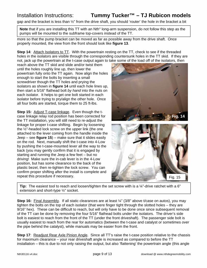
more so that the pump bracket can be moved as far as possible away from the drive shaft. Once properly mounted, the view from the front should look like figure 13. Step 14: Attach Isolators to TT. With the powertrain resting on the TT, check to see if the threaded holes in the isolators are visible through the corresponding countersunk holes in the TT skid. If they are not, jack up the powertrain at the t-case output again to take some of the load off of the isolators, then reach above the TT skid and slide and/or twist them until the holes roughly line up, then lower the powertrain fully onto the TT again. Now align the holes enough to start the bolts by inserting a small screwdriver though the TT holes and prying the isolators as shown in figure 14 until each hole lines up, then start a 5/16” flathead bolt by hand into the nuts on each isolator. It helps to get one bolt started in each isolator before trying to pry/align the other hole. Once all four bolts are started, torque them to 25 ft-lbs. Step 15: Adjust T-case linkage. Even though the t-case linkage relay rod position has been corrected for the TT installation, you will still need to re-adjust the linkage for proper t-case shifting. Begin by loosening the ½”-headed lock screw on the upper link (the one attached to the lever coming from the handle inside the Jeep – see figure 15) – make sure that it slides easily on the rod. Next, manually shift the t-case into 4-Low by pushing the t-case-mounted lever all the way to the back (you may gently confirm that it is engaged by starting and running the Jeep a few feet – but no driving! Make sure the in-cab lever is in the 4-Low position, but has some clearance to the back of the plastic bezel, then re-tighten the lock screw. You can confirm proper shifting after the install is complete and repeat this procedure if necessary.
Step 16: Final Assembly. If all static clearances are at least ¼” (3/8” above t/case on autos), you may tighten the bolts on the top of each isolator (that were finger tight through the slotted holes – they are 9/16” hex). These can be difficult to reach, but will only have to be done once since subsequent removal of the TT can be done by removing the four 5/16” flathead bolts under the isolators. The driver’s side bolt is easiest to reach from the front of the TT (under the front driveshaft). The passenger side bolt is usually easiest to reach from the rear for automatics (between the t-case and catalyst or sometimes over the pipe behind the catalyst), while manuals may be easier from the front. Step 17: Readjust Rear Axle Pinion Angle. Since all TT’s raise the t-case position relative to the chassis for maximum clearance – your rear driveshaft angle is increased as compared to before the TT installation – this is due to not only raising the output, but also ‘flattening’ the powertrain angle (this angle
Note that if you are installing this TT with an Nth° long-arm suspension, do not follow this step as the pumps will be mounted to the subframe top-covers instead of the TT.
Installation Instructions: Tummy Tucker™ – TJ Rubicon models
Nth30116 v4.doc page 10 of 13 download @ www.nthdegreemobility.com
DO NOT use a torch or plasma cutter, etc. to clearance the isolator housing because you will light the rubber on fire and need a new shifter cane!
remains close to stock if you use a drop TT with a motor mount lift.) Both your operating angle and ideal nominal length are affected by installing a TT because it raises the rear output by about 1.25”. Generally installation of a TT does not require a longer driveshaft than the one already installed. The only TT installation that does not require a custom ‘CV’ driveshaft is on Rubicon TJ’s with ZERO suspension lift. For all others, it is assumed that a proper length ‘CV’ driveshaft is installed, but you will now need to readjust the rear axle pinion angle higher with the TT versus with the stock skid plate. This adjustment requires the use of an Nth° Stinger™ or Nth° adjustable rear upper control arms (or others that may have come with your lift kit.) Ideal pinion angle is usually about 1.5+/-0.5 degrees ‘flatter’ than the drive shaft’s angle.
Once you have readjusted the pinion angle, you should measure the relative angle between the driveshaft and the powertrain (t-case) – this is the ‘operating angle’ of the double Cardan joint. You can get a powertrain angle from various places such as the driveshaft output flange or engine damper pulley, but do not use the engine or transmission oil pans – they are not accurate enough. The double-Cardan joint on your custom rear drive shaft cannot run vibration-free if its operating angle is over 22 degrees. If it is, you will likely need to make changes to solve vibrations – consult the appendix for more information. Step 18: Shifter Clearance Modification – ‘04+ Manual Transmission Vehicles Only. Late in the 2003 model year, Jeep and New Venture Gear changed the design of the shifter cane isolator, so the following procedure applies to all ‘04+ models and a few ’03 Wranglers (if you are using a 1.25” drop TT with a body and motor mount lift, you probably will not require this step). Like the old design, the new shifter ‘cane’ has a large rubber isolator encased in a metal housing, but the new design can be identified by the fact that this isolator is in front of the main shaft (instead of in line with it), and attaches via a bolt down the center of the isolator. With the TT installed, this new oversized-and-forward-mounted isolator will hit the surrounding plastic of the center console when the trans is in 1st, 3rd, and maybe even 5th gears – this will cause the transmission to ‘pop’ out of these gears under high-rpm load unless corrected. To correct the issue, first loosen the shifter boot base from the center console by gently squeezing the plastic frame at the base of the boot in the center of the front and back surfaces until it comes free. You will now be able to see where the interference occurs when you place the trans in 1st gear – mark this area on the front side of the shifter isolator’s metal housing. Next, remove the upper portion of the shifter along with the isolator by removing the vertical bolt that goes down through the top of the isolator. Use any type of grinder to create a ‘window’ in the front of the housing and into the rubber approximately ¼” deep - this will not adversely affect the function of the isolator or its integrity, but will provide the needed clearance as shown in figure 16. Once clearanced, reinstall the shifter for the next step, but reinstall the boot after the test drive.
Step 19: Test Drive. Once all fasteners are properly torqued and all supports removed, test drive the Jeep to check for vibrations or clearance issues, but before you start the engine, make sure to check for clearance between the engine cooling fan and the bottom of the shroud. If the fan is ‘stuck’ on the shroud or very close to it (under ¼”), go to the appendix for the solution first. When you start the engine, you may notice 3-4 ‘jolts’ just as the engine starts running. This is normal and is a result of the new dual-mount system you installed with the TT. It is a small trade-off for the additional control over powertrain motion that the dual mounts provide -which in turn keeps the trans/t-case position under control so that they don’t knock against the tunnel, TT, etc. Once running, you should not feel or hear any new ‘buzzing’ or rattling. If you do, this indicates contact between the

Installation Instructions: Tummy Tucker™ – TJ Rubicon models
Nth30116 v4.doc page 11 of 13 download @ www.nthdegreemobility.com
Caution: Debris Accumulation on top of TT. The TT does not have any large clearance or drainage holes on the bottom surface to eliminate the possibility of snagging a rock, etc. in such holes. On the other hand, the lack of holes and the reduced clearances around the transmission, transfer case, and exhaust, makes it easier for rocks, twigs, etc. to accumulate on top of the skid plate and not fall out on their own. Flammable items such as grass and twigs should be kept out of contact with the hot exhaust or there will be risk of fire – you should clear the TT after each off-road outing to avoid danger! Also, (especially on manual transmissions), rocks or other hard items may get lodged under the transmission adapter bracket – where they will effectively eliminate the isolation proved by the dual mounts (you may notice more vibration), and if left uncleared this could cause the mounts to deteriorate. Every effort has been made to prevent this from happening, but you should check for rocks and clear them if found.
TT on ’03 Rubicon automatic with optional auto trans skid
powertrain and the TT or body floor. Find the contact and correct as necessary with shims, more floor mods, etc. (see appendix). Contact during certain rough conditions may occur and is generally not detrimental – you can test for some things by doing hard launches (t-case may touch floor), and compression braking (t-case may touch TT) – if the contact is detectable, it may be desirable to increase the appropriate clearance area. You can also test drive over washboard, but the contact will be hard to hear – if you provided the proper ¼+” clearances, you will rarely hit and not damage anything.
Next, confirm that the t-case shift linkage still functions properly – that you can get into and out of both 2-High and 4-Low. If not, the linkage may need readjustment. See the appendix section for solutions to possible issues that have been found in rare cases.
Note: if you have an automatic and hear 3-4 ‘thumps’ during a hard launch, you don’t have enough clearance at the dimple. Automatic TJ’s require more clearance due to the torque ‘pulses’ created by the torque converter. If you already have made the dimple as large as possible (tires were off the ground), you may need to shim the TT skid down at the frame rails using six ½” washers (about 1/8” thick) – this can be done without removing the skid (do one side at a time) and should eliminate the issue.

Installation Instructions: Tummy Tucker™ – TJ Rubicon models
Nth30116 v4.doc page 12 of 13 download @ www.nthdegreemobility.com
Appendix: Installation Issues and Additional Modification Solutions Issue: Vibration while driving. Since drive shaft angles and related vibrations are affected by many factors besides the TT, including lift height, etc., Nth Degree does not include the means to correct driveline angles with any TT kit and full-price returns are not granted for vibration issues. If you have any suspension lift on your Rubicon at all, you must have a double Cardan rear drive shaft and a means to adjust your rear axle pinion angle.
Be sure the vibration is not out-of-balance tires, etc. by noting the ‘speed’ of the vibration – tire vibrations are much slower than drive shafts due to the axle ratio. Also, an out-of-balance drive shaft (due to lost weights or bent, etc.) will vibrate steadily and the intensity will increase evenly with vehicle speed (like a tire, but faster as mentioned). Vibrations due to bad joint angles will generally have speed ranges where the vibration intensifies and others where it nearly disappears. Also an angle-induced vibration will be cyclical – it will ‘drone’ in and out at a given vehicle speed. .If you have issues and don’t know what to do, here are some tips: Solution Suggestions: In general, if your suspension lift height is under +5” and you have a double cardan drive shaft, and a (standard) low pinion rear axle, your should be able to cure most drive shaft angle-related vibration issues below 80 mph by fine-tuning the pinion angle. However, tire size, axle ratio, etc. are also factors, so the ‘solution’ may not be as simple as pinion angle. If you are using relatively small tires for your axle ratio (such as 33’s with 4.56 gears), your driveshaft spins faster at a given speed and makes eliminating vibrations harder. Some steps to diagnose the problem after verifying it is not a balance issue:
First, confirm that your relative joint angle at the axle pinion joint is about 1.5 degrees, with the pinion flatter than the driveshaft – if not, correct this first. Second, check the relative angle at the t-case end – it should be no more than 22 degrees. If it is more, you may have to choose a combination of ways to reduce the angle - these can include: shimming the TT down at the frame, adding/increasing the motor mount lift, lowering the lift height, using a high pinion rear axle, or installing a special high-operating-angle drive shaft such as a Bigelow/Cornay joint (not just a ‘clearanced’ joint). If you are using a custom driveshaft that uses an adapter to the factory output flange, you can also reduce the angle by 1-2 degrees or more by changing to a yoke-type output and eliminating the damper and flange – this will require a new driveshaft that has a yoke-type CV joint and can be about 1.5” longer than the flange-type CV driveshaft.
If you are having a vibration issue that is dependent on your driving (turning left, accelerating hard, etc.), the issue may not be angles but contact somewhere between rotating parts and non-rotating ones – or light contact to the body floor. Check for clearance around both drive shafts including screws protruding from the floor, etc. Keep in mind that the t-case front output rises during acceleration (may touch floor) and drops during compression braking (may touch TT). If you have an automatic and feel 3 to 4 mild ‘thumps’ during a hard launch from standing still that seem to come from right under the driver’s seat, you need more clearance at the dimple from step 4. Issue: Vibration while Idling. If you notice significantly more vibration while sitting still with the engine running, the issue is most likely that there is contact somewhere between the powertrain and the body floor or TT. These should have been caught and corrected in step 12, but something may have been overlooked or too hidden to detect visually. Solution Suggestions: Thoroughly inspect the area above the TT for any contact between parts that was missed previously. On 4-speed automatics, especially check the clearance above the bellhousing as mentioned in step 4a.
Also check the t-case linkage relay rod and confirm that it is not bound up or plunged to the point where it is contacting the tunnel though the tunnel-end bracket. If the linkage is not close to horizontal, it may be binding and the vibration is then transmitted to the interior through the rod. You can try disconnecting the relay rod to test if it is the ‘noise path’.
Another possibility is wrong or incorrectly installed isolators. Make sure that the isolators are sitting flat on the TT and have a uniform, slightly conical shape. If they appear distorted to one side, front, or back, or are otherwise unevenly shaped, there is an unnatural preload on them that should not be

Installation Instructions: Tummy Tucker™ – TJ Rubicon models
Nth30116 v4.doc page 13 of 13 download @ www.nthdegreemobility.com
present – check for crooked/misinstalled/bent brackets, bad motor mounts or motor mount spacing, etc. If their appearance is okay, verify their height while they are supporting the powertrain with the engine off. They should be about 1.0” to 1-1/16” tall from the surface of the TT to their tops (not counting any shims above them). Issue: Exhaust is too high over rear axle and at tailpipe and the hangers at muffler and tailpipe are not ‘hanging’ and/or exhaust is touching heat shield over rear axle. Since the TT installation does slightly elevate the center portion of the exhaust relative to the floor, the rear portion may require adjustment to keep it in its proper place. If this did not happen ‘naturally’ via some ‘sag’ at the joint between the catalytic converter and the muffler, you may need to make this adjustment deliberately. Solution: On ‘03+ TJ’s there is a joint in the system made up of two large flanges that are held together with two bolts - this connection is just ahead of the muffler. By loosening the two bolts, the exhaust should drop back into place, then retighten the bolts. If the hanger at the back of the muffler is still not fully ‘hanging’, bend the rod that is welded to the exhaust pipe slightly forward. The exhaust grows in length when it warms up, so the hanger will swing into position during operation.
If your exhaust system is custom, you may or may not have a joint ahead of the muffler and it may be necessary to visit a muffler shop to do a proper adjustment. Issue: Engine Fan is touching fan shroud (static), or fan can be heard touching shroud while driving over bumps, etc. Wrangler front-end sheetmetal is only supported by one body mount forward of the firewall, consequently, there can be major variation (up to an inch!) in the position of the grille along with the radiator and fan shroud. Normal TT installations tip the powertrain ‘flatter’ to the point where the engine fan may touch the bottom lip of the fan shroud if the sheetmetal on your Jeep happens to be ‘high’. You need at least ¼” clearance between the tips of the blades and the shroud, though more is desirable - if you have less, you need to fix it. Solution: The easiest solution is to lower the fan shroud. Remove the shroud from the radiator and slip it over the fan (you may have to unbolt the fan to do this). Use a small round file or similar to ‘router’ the mounting holes upward towards the top of the shroud. If you cannot gain enough clearance before the holes are too close to the ribs in the shroud, you can also do the same to the radiator mounting flanges where it bolts to the grille, but this is almost never necessary for drop TT installations. Not that if you are using a body lift without a motor mount lift, you already had to make a fan shroud correction that may have not been sufficient for use with the TT. Issue: Manual transmission sometimes pops out of first gear. If you have a late production 2003 Wrangler or have had transmission work done, the dealer may have updated your shifter to the new design described in step 18, and you will need to perform that step. If you have an ‘04+ Rubicon and did not perform step 18, this problem confirms that you need to do it.